Embed Size (px)
Citation preview
2017
Mohit M. Jain
M.jain
3/18/2017
Geometric Design Of Railway Track

Geometric Desing of Railway Track Page 1
GUJARAT TECHNOLOGICAL UNIVERSITY
Chandkheda, Ahmedabad
A Project Report
On
“Geometric Design Of Railway Track”
Under subject of
RAILWAY, BRIDGE & TUNNEL ENGINEERING
(2160603)
Submitted by:
Mohit M. Jain
140420106025
Guided By:
Prof. Vishwa Mehta
(Faculty Guide)
Department of Civil Engineering
Sarvajanik College of Engineering &Technology,
Athwalines, Surat.
Geometric Desing of Railway Track Page 2
SARVAJANIK COLLEGE OF ENGINEERING & TECHNOLOGY,
ATHWALINES, SURAT.
CIVIL ENGINEERING DEPARTMENT
CERTIFICATE
Date: This is to certify that the Report entitled “ Geometric Design Of Railway Track” has been carried out by Jain Mohit(140420106025). Under my guidance in fulfilment of the Degree of B.E. in Civil Engineering (6
rd semester)
of Gujarat Technological University, Ahmadabad during the academic year 2015-16.
Prof. Vishwa Mehta Prof. Pratima Patel
(Faculty Guide) Associate Professor & Head,
Civil Engineering Department Civil Engineering Department
EXTERNAL EXAMINER
Geometric Desing of Railway Track Page 3
ACKNOWLEDGEMENT
Behind every success there are lot many efforts, but efforts are fruitful
due to hands making the passage smoother. We express our deep sense of
gratitude for hands, people extended to us during our work.
Research brings about dramatic changes in the traditional look out of
science & technology. It is continuous phenomenon under taken by one and
every throughout the world. It has widened our vision, opened newer avenues
and lightened the dark obscure facets of mysteries universe. The work depicted
in this thesis is a bucketful of contribution to the large ocean of research
occurring globally. As one flower makes no garland, this presentation would not
have taken shape without wholehearted encouragement and live involvement of
some generous souls.
We express sincere and heartfelt thanks to Dr.Vaishali Mungurwadi,
Principal, and Associate Professor Pratima Patil, (Head of Civil Engineering
Department), Sarvajanik College Of Engineering & Technology for giving us
an opportunity to undertake this research subject for study.
We express a deep sense of gratitude to my guide Prof. Vishwa Mehta, Civil
Engineering Department, Sarvajanik College Of Engineering & Technology
for her constructive support, constant encouragement, guidance and challenging
our efforts in the right direction without which this thesis would not have
attained the present form.
Geometric Desing of Railway Track Page 4
Contents
Chapter 1: Introduction .............................................................................................................. 5
1.1 Introduction ................................................................................................................. 5
Chapter 2: Necessity................................................................................................................... 6
2.1 Necessity ........................................................................................................................... 6
Chapter 3: GEOMETRIC CROSS SECTION ........................................................................... 6
3.1 CrossSection ..................................................................................................................... 6
Chapter 4: Gradients................................................................................................................... 8
4.1 Gradient............................................................................................................................. 8
4.2 Types of gradients ............................................................................................................. 8
4.2. (a) Ruling Gradient .......................................................................................................... 9
4.2. (b) Pusher or Helper Gradient ........................................................................................ 10
4.2. (c) Momentum gradient ................................................................................................. 10
4.2. (d) Gradients in station yards ......................................................................................... 11
4.2. (e) Grade Compensation on Curves ............................................................................... 12
Chapter 5: Curves ..................................................................................................................... 13
5.1 Curves ............................................................................................................................. 13
5.2 Maximum Degree of a Curve ......................................................................................... 13
Chapter 6: Superelevation ........................................................................................................ 14
6.1 Superelevation................................................................................................................. 14
6.2 Objective Of Providing Superelevation .......................................................................... 14
6.3 Centrifugal Force on a Curved Track ............................................................................. 14
6.4 Formula for Superelevation ............................................................................................ 16
6.5 Thumb Rules for Calculating Superelevation in the Field.............................................. 16
6.6 Types of Cant .................................................................................................................. 17
6.6.1 Equilibrium cant........................................................................................................... 17
6.6.2 Cant deficiency ( Cd ) .................................................................................................. 17
6.6.3 Cant excess ( Ce ) ........................................................................................................ 17
Chapter 7: Widening of Gauge on Curve ................................................................................. 18
7.1 Widening of Gauge on Curve .................................................................................... 18

Geometric Desing of Railway Track Page 5
Chapter 1: Introduction
1.1 Introduction
Geometric design for transportation facilities includes the design of
geometric cross sections, horizontal alignment, vertical alignment, intersections,
and various design details. These basic elements are common to all linear
facilities, such as roadways, railways, and airport runways and taxiways.
Although the details of design standards vary with the mode and the class of
facility, most of the issues involved in geometric design are similar for all
modes. In all cases, the goals of geometric design are to maximize the comfort,
safety, and economy of facilities, while minimizing their environmental
impacts. This chapter focuses on the fundamentals of geometric design, and
presents standards and examples from different modes.
The order of presentation of material in this chapter is to consider
geometric cross sections first, then vertical alignment, horizontal alignment,
super elevation , and various design details. For purposes of exposition, the
order of the topics is not very important. In a typical design project, on the other
hand, there is a definite order of tasks, in which the establishment of a tentative
horizontal centreline usually precedes establishment of vertical alignment. This
is because the elevation of the existing ground along the centreline is an
important consideration in establishing the vertical alignment. The process of
designing the vertical alignment begins with plotting a profile of the existing
terrain, and a tentative horizontal centreline must already be established in order
to do this.
Geometric Desing of Railway Track Page 6
Chapter 2: Necessity
2.1 Necessity
The need for proper geometric design of a track arises because of the
following considerations :
o To ensure the smooth and safe running of trains
o To achieve maximum speeds
o To carry heavy axle loads
o To avoid accidents and derailments due to a defective permanent
way
o To ensure that the track requires least maintenance.
o For good aesthetics
Chapter 3: GEOMETRIC CROSS SECTION
3.1 Cross Section
The primary consideration in the design of geometric cross sections for
highways, runways, and taxiways is drainage. Details vary depending on the
type of facility and agency.
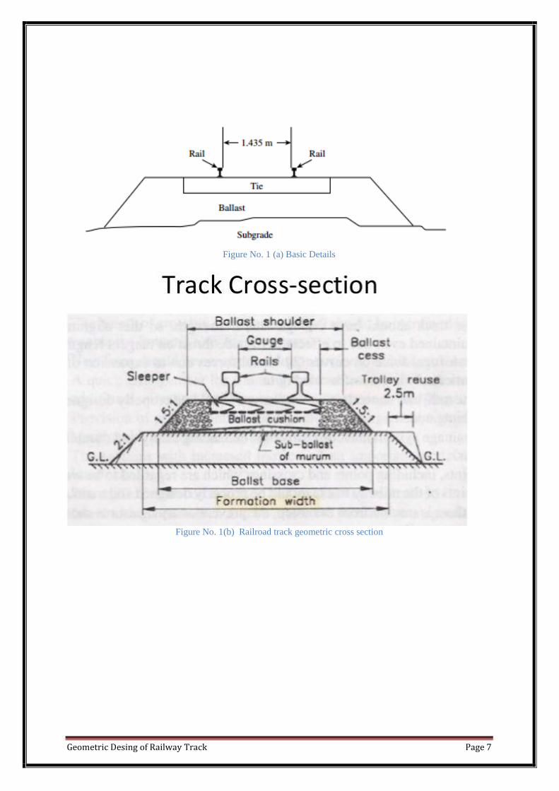
Railway cross sections are as shown in Fig.1. The distance between the
rails, as shown in the figure, is what is known as standard gage in North
America. Other gauges are sometimes used. In the case of railroad track, the
shape of the cross section is not intended to provide drainage, since the ballast,
which is permeable material, serves this purpose.
Geometric Desing of Railway Track Page 7
Figure No. 1 (a) Basic Details
Figure No. 1(b) Railroad track geometric cross section
Geometric Desing of Railway Track Page 8
Chapter 4: Gradients
4.1 Gradient
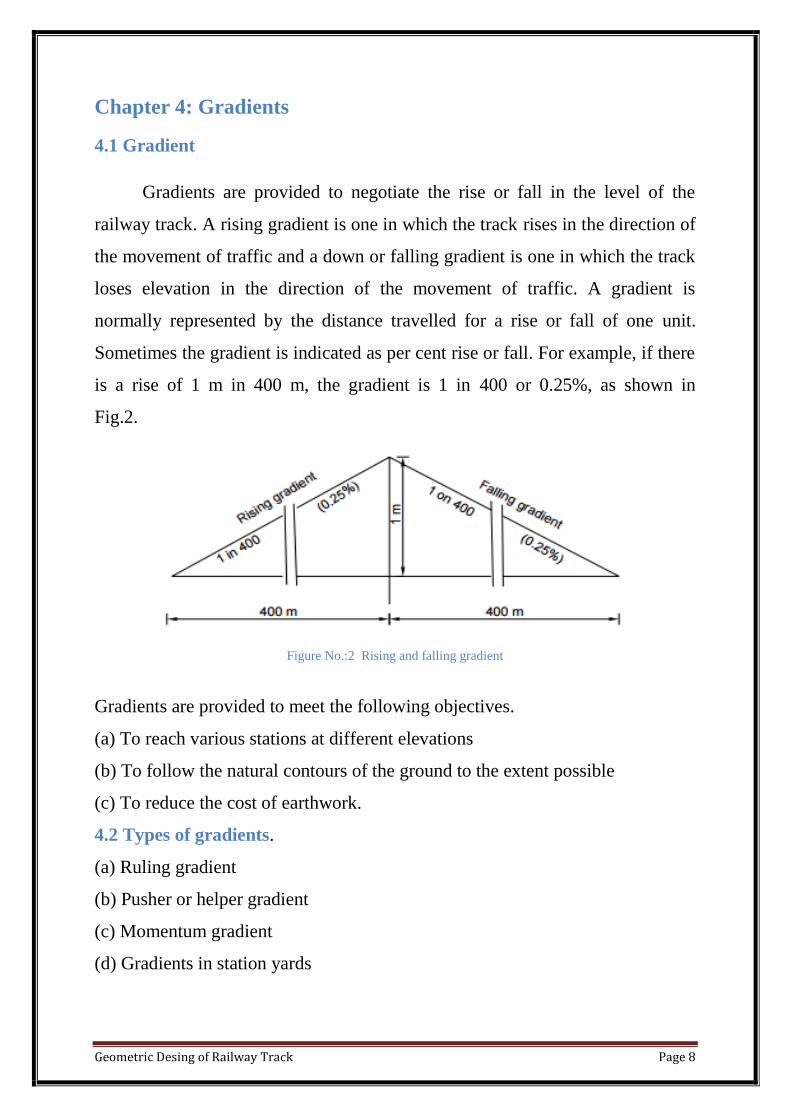
Gradients are provided to negotiate the rise or fall in the level of the
railway track. A rising gradient is one in which the track rises in the direction of
the movement of traffic and a down or falling gradient is one in which the track
loses elevation in the direction of the movement of traffic. A gradient is
normally represented by the distance travelled for a rise or fall of one unit.
Sometimes the gradient is indicated as per cent rise or fall. For example, if there
is a rise of 1 m in 400 m, the gradient is 1 in 400 or 0.25%, as shown in
Fig.2.
Figure No.:2 Rising and falling gradient
Gradients are provided to meet the following objectives.
(a) To reach various stations at different elevations
(b) To follow the natural contours of the ground to the extent possible
(c) To reduce the cost of earthwork.
4.2 Types of gradients.
(a) Ruling gradient
(b) Pusher or helper gradient
(c) Momentum gradient
(d) Gradients in station yards
Geometric Desing of Railway Track Page 9
4.2. (a) Ruling Gradient
The ruling gradient is the steepest gradient that exists in a section. It
determines the maximum load that can be hauled by a locomotive on that
section. While deciding the ruling gradient of a section, it is not only the
severity of the gradient but also its length as well as its position with respect to
the gradients on both sides that have to be taken into consideration. The power
of the locomotive to be put into service on the track also plays an important role
in taking this decision, as the locomotive should have adequate power to haul
the entire load over the ruling gradient at the maximum permissible speed.
The extra force P required by a locomotive to pull a train of weight W on
a gradient with an angle of inclination θ is , Rising gradient 1 in 400 (0.25%)
Falling gradient (0.25%) 1 on 400
P = W Sinθ
= W tanθ (approximately, as θ is very small)
= W × gradient
Indian Railways does not specify any fixed ruling gradient owing to
enormous variations in the topography of the country, the traffic plying on
various routes, and the speed and type of locomotive in use on various sections.
Generally, the following ruling gradients are adopted on Indian Railways when
there is only one locomotive pulling the train.
In plain terrain: 1 in 150 to 1 in 250
In hilly terrain: 1 in 100 to 1 in 150
Once a ruling gradient has been specified for a section, all other gradients
provided in that section should be flatter than the ruling gradient after making
due compensation for curvature.

Geometric Desing of Railway Track Page 10
Figure No.:3 Ruling Gradient
4.2. (b) Pusher or Helper Gradient
In hilly areas, the rate of rise of the terrain becomes very important when
trying to reduce the length of the railway line and, therefore, sometimes
gradients steeper than the ruling gradient are provided to reduce the overall cost.
In such situations, one locomotive is not adequate to pull the entire load, and an
extra locomotive is required.
When the gradient of the ensuing section is so steep as to necessitate the
use of an extra engine for pushing the train, it is known as a pusher or helper
gradient. Examples of pusher gradients are the Budni–Barkhera section of
Central Railways and the Darjeeling Himalayan Railway section.
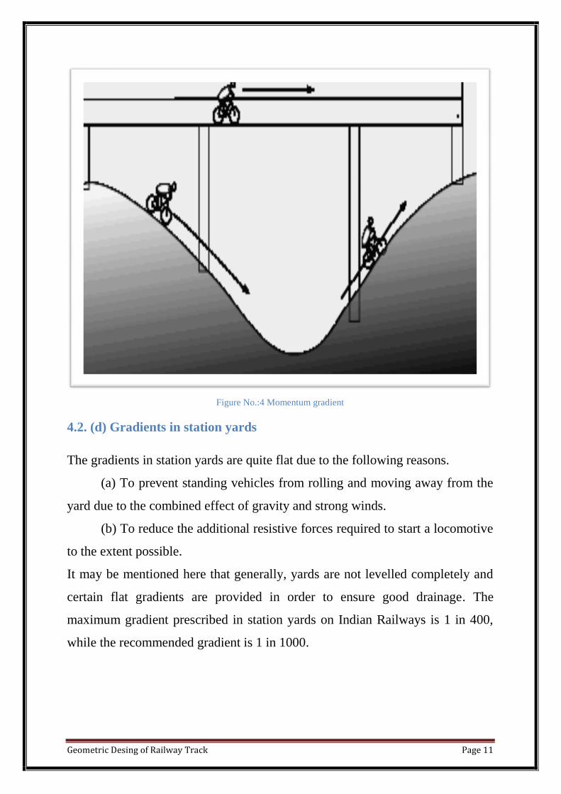
4.2. (c) Momentum gradient
The momentum gradient is steeper than the ruling gradient and can be
overcome by a train because of the momentum it gathers while running on the
section. In valleys, a falling gradient is sometimes followed by a rising gradient.
In such a situation, a train coming down a falling gradient acquires good speed
and momentum, which gives additional kinetic energy to the train and allows it
to negotiate gradients steeper than the ruling gradient. In sections with
momentum gradients there are no obstacles provided in the form of signals, etc.,
which may bring the train to a critical juncture
Geometric Desing of Railway Track Page 11
Figure No.:4 Momentum gradient
4.2. (d) Gradients in station yards
The gradients in station yards are quite flat due to the following reasons.
(a) To prevent standing vehicles from rolling and moving away from the
yard due to the combined effect of gravity and strong winds.
(b) To reduce the additional resistive forces required to start a locomotive
to the extent possible.
It may be mentioned here that generally, yards are not levelled completely and
certain flat gradients are provided in order to ensure good drainage. The
maximum gradient prescribed in station yards on Indian Railways is 1 in 400,
while the recommended gradient is 1 in 1000.
Geometric Desing of Railway Track Page 12
4.2. (e) Grade Compensation on Curves
Curves provide extra resistance to the movement of trains. As a result, gradients
are compensated to the following extent on curves:
(a) On BG tracks, 0.04% per degree of the curve or 70/R, whichever is
minimum.
(b) On MG tracks, 0.03% per degree of curve or 52.5/R, whichever is
minimum.
(c) On NG tracks, 0.02% per degree of curve or 35/R, whichever is
minimum where R is the radius of the curve in metres.
The gradient of a curved portion of the section should be flatter than the ruling
gradient because of the extra resistance offered by the curve.
Example:
Find the steepest gradient on a 2° curve for a BG line with a ruling gradient of 1
in 200.
Solution
(i) Ruling gradient = 1 in 200 = 0.5%
(ii) Compensation for a 2° curve = 0.04 × 2 = 0.08%
(iii) Compensated gradient = 0.5 – 0.08 = 0.42% = 1 in 238
The steepest gradient on the curved track is 1 in 238.
Geometric Desing of Railway Track Page 13
Chapter 5: Curves
5.1 Curves
Curves are introduced on a railway track to bypass obstacles, to provide
longer and easily traversed gradients, and to pass a railway line through
obligatory or desirable locations.
Horizontal curves are provided when a change in the direction of the track
is required and Vertical curves are provided at points where two gradients meet
or where a gradient meets level ground.
Curve is defined either by radius or its degree
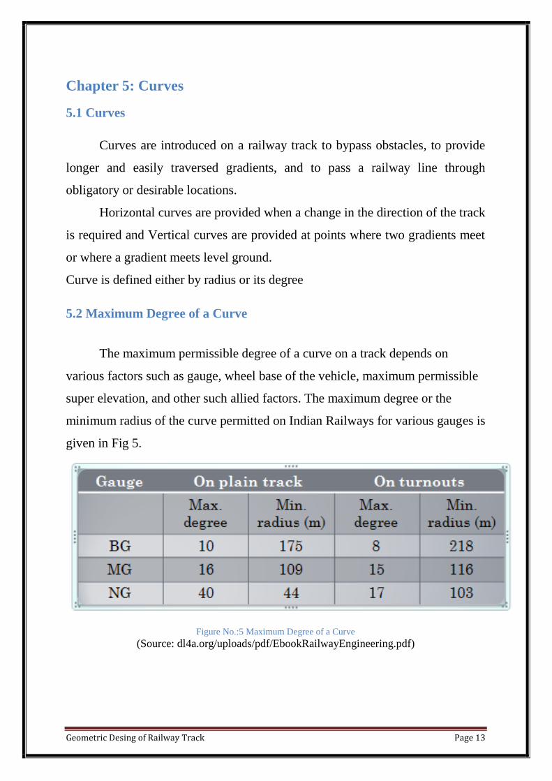
5.2 Maximum Degree of a Curve
The maximum permissible degree of a curve on a track depends on
various factors such as gauge, wheel base of the vehicle, maximum permissible
super elevation, and other such allied factors. The maximum degree or the
minimum radius of the curve permitted on Indian Railways for various gauges is
given in Fig 5.
Figure No.:5 Maximum Degree of a Curve
(Source: dl4a.org/uploads/pdf/EbookRailwayEngineering.pdf)
Geometric Desing of Railway Track Page 14
Chapter 6: Superelevation
6.1 Superelevation
The following terms are frequently used in the design of horizontal
curves. Superelevation or cant (Ca) is the difference in height between the outer
and the inner rail on a curve. It is provided by gradually lifting the outer rail
above the level of the inner rail. The inner rail is taken as the reference rail and
is normally maintained at its original level. The inner rail is also known as the
gradient rail.
6.2 Objective Of Providing Superelevation
The main functions of superelevation are the following :
(a) To ensure a better distribution of load on both rails
(b) To reduce the wear and tear of the rails and rolling stock
(c) To neutralize the effect of lateral forces
(d) To provide comfort to passengers
6.3 Centrifugal Force on a Curved Track
A vehicle has a tendency to travel in a straight direction, which is
tangential to the curve, even when it moves on a circular curve. As a result, the
vehicle is subjected to a constant radial acceleration:
Radial acceleration = g = V2 /R
Where, V = velocity (metres per second) and
R = Radius of curve (metres).
This radial acceleration produces a centrifugal force which acts in a radial
direction away from the centre.
Geometric Desing of Railway Track Page 15
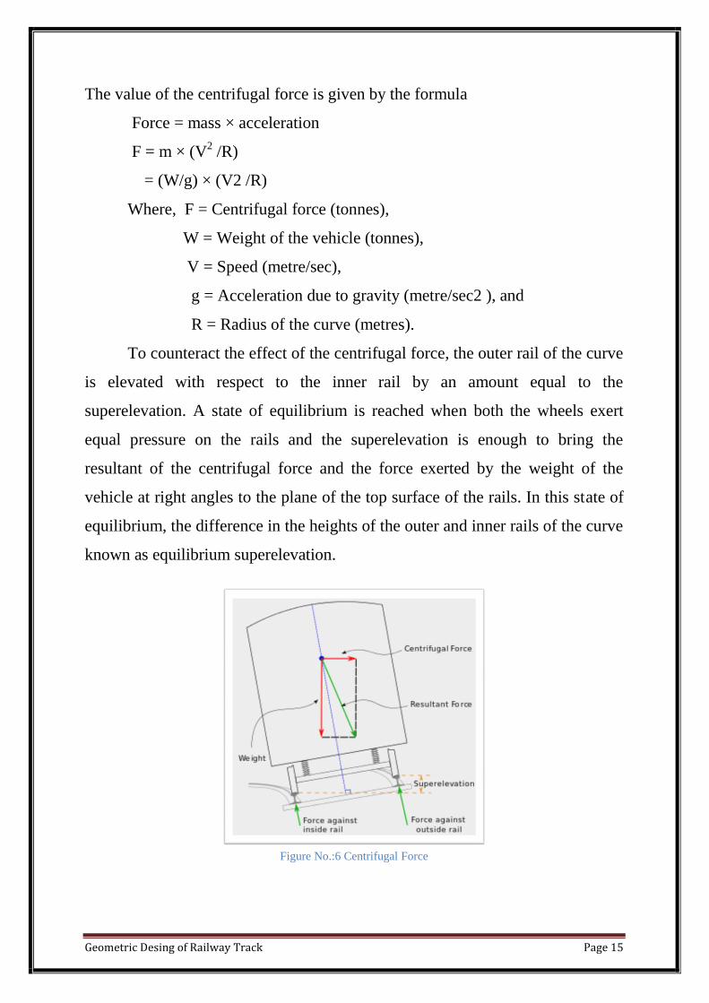
The value of the centrifugal force is given by the formula
Force = mass × acceleration
F = m × (V2 /R)
= (W/g) × (V2 /R)
Where, F = Centrifugal force (tonnes),
W = Weight of the vehicle (tonnes),
V = Speed (metre/sec),
g = Acceleration due to gravity (metre/sec2 ), and
R = Radius of the curve (metres).
To counteract the effect of the centrifugal force, the outer rail of the curve
is elevated with respect to the inner rail by an amount equal to the
superelevation. A state of equilibrium is reached when both the wheels exert
equal pressure on the rails and the superelevation is enough to bring the
resultant of the centrifugal force and the force exerted by the weight of the
vehicle at right angles to the plane of the top surface of the rails. In this state of
equilibrium, the difference in the heights of the outer and inner rails of the curve
known as equilibrium superelevation.
Figure No.:6 Centrifugal Force
Geometric Desing of Railway Track Page 16
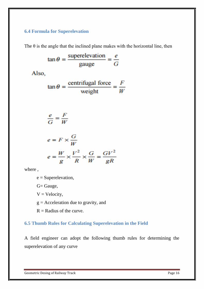
6.4 Formula for Superelevation
The θ is the angle that the inclined plane makes with the horizontal line, then
where ,
e = Superelevation,
G= Gauge,
V = Velocity,
g = Acceleration due to gravity, and
R = Radius of the curve.
6.5 Thumb Rules for Calculating Superelevation in the Field
A field engineer can adopt the following thumb rules for determining the
superelevation of any curve
Geometric Desing of Railway Track Page 17
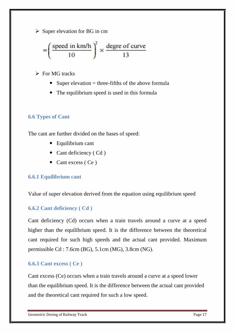
Super elevation for BG in cm
For MG tracks
Super elevation = three-fifths of the above formula
The equilibrium speed is used in this formula
6.6 Types of Cant
The cant are further divided on the bases of speed:
Equilibrium cant
Cant deficiency ( Cd )
Cant excess ( Ce )
6.6.1 Equilibrium cant
Value of super elevation derived from the equation using equilibrium speed
6.6.2 Cant deficiency ( Cd )
Cant deficiency (Cd) occurs when a train travels around a curve at a speed
higher than the equilibrium speed. It is the difference between the theoretical
cant required for such high speeds and the actual cant provided. Maximum
permissible Cd : 7.6cm (BG), 5.1cm (MG), 3.8cm (NG).
6.6.3 Cant excess ( Ce )
Cant excess (Ce) occurs when a train travels around a curve at a speed lower
than the equilibrium speed. It is the difference between the actual cant provided
and the theoretical cant required for such a low speed.
Geometric Desing of Railway Track Page 18
Chapter 7: Widening of Gauge on Curve
7.1 Widening of Gauge on Curve
When vehicle moves onto a curve, the flange of the outside wheel of the
leading axle continues to travel in a straight line till it rubs against the rail. Due
to the coning of wheels ,the outside wheel travels a longer distance compared to
the inner wheel. In an effort to make up for the difference in the distance
travelled by the outer wheel and the inner wheel, the inside wheels slip
backward and the outer wheels skid forward.
The widening of the gauge on a curve has, in fact, tends to decrease the wear
and tear on both the wheel and the track
The widening of the gauge on curves can be calculated using the formula
Extra width on curves
w = 13(B+L)2/R
Where,
B is the wheel base of the vehicle in metres,
R is the radius of the curve in metres,
L =0.02(h2 + Dh)
1/2 is the lap of the flange in metres,
h is the depth of flange below top of the rail(cm),
D is the diameter of the wheel of the vehicle (cm).
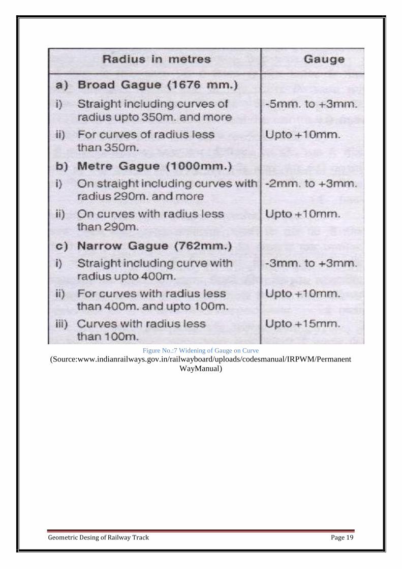
Geometric Desing of Railway Track Page 19
Figure No.:7 Widening of Gauge on Curve
(Source:www.indianrailways.gov.in/railwayboard/uploads/codesmanual/IRPWM/Permanent
WayManual)
Geometric Desing of Railway Track Page 20
Chapter 8: References
http://dl4a.org/uploads/pdf/EbookRailwayEngineering
http://trainguard.in/horizontalcurve&submit&posttypeproduct
http://www.indianrailways.gov.in/railwayboard/uploads/codesmanual/IR
PWM/PermanentWayManual
http://teacher.buet.ac.bd/cfc/curve