Embed Size (px)
Citation preview
DIFFERENT TYPE S OF POWER CONVERTERS FED RELUTANCE
MOTOR
NAME-KUSHALESWAR MEHER
REG NO-1421227042
BRANCH-ELECTRICAL SEC-3C
SUBMITTED TO-ASST. PROF. J C PATI
ABSTRACT This paper presents requirements, detailed analysis, and operation of six
converter types used with 3-phase 6/4 switched reluctance motor (SRM). These converters are R-dump, C-dump, C-dump with freewheeling transistor, asymmetric, series, and parallel type. The simulation results are made by MATLAB/SIMULINK package. The paper also introduced why the asymmetric bridge converter type is the best one especially for high speeds.
CONTENTS INTRODUCTION REQUIREMENTS OF SRM CONVERTERS TYPE OF SRM CONVERTERS SIMULATION RESULTS FOR SRM CONVERTERS COMPARISOIN BETWEEN THE SIMULATION RESULTS MOTOR DATA CONCLUSION REFERENCES
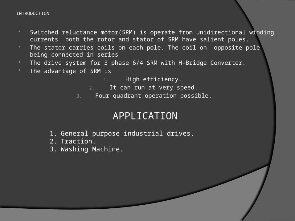
INTRODUCTION
Switched reluctance motor(SRM) is operate from unidirectional winding currents. both the rotor and stator of SRM have salient poles.
The stator carries coils on each pole. The coil on opposite pole being connected in series
The drive system for 3 phase 6/4 SRM with H-Bridge Converter. The advantage of SRM is
1. High efficiency.2. It can run at very speed.
3. Four quadrant operation possible.
APPLICATION
1. General purpose industrial drives.2. Traction.3. Washing Machine.
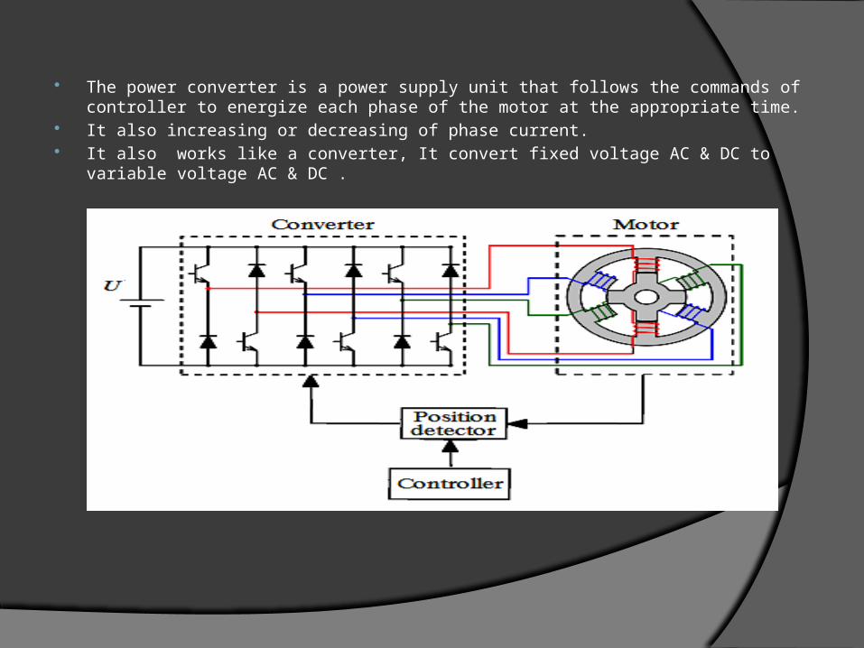
The power converter is a power supply unit that follows the commands of controller to energize each phase of the motor at the appropriate time.
It also increasing or decreasing of phase current. It also works like a converter, It convert fixed voltage AC & DC to variable voltage AC
& DC .
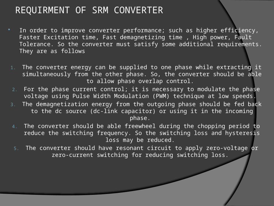
REQUIRMENT OF SRM CONVERTER In order to improve converter performance; such as higher efficiency, Faster Excitation
time, Fast demagnetizing time , High power, Fault Tolerance. So the converter must satisfy some additional requirements. They are as follows
1. The converter energy can be supplied to one phase while extracting it simultaneously from the other phase. So, the converter should be able to allow phase overlap control.
2. For the phase current control; it is necessary to modulate the phase voltage using Pulse Width Modulation (PWM) technique at low speeds.
3. The demagnetization energy from the outgoing phase should be fed back to the dc source (dc-link capacitor) or using it in the incoming phase.
4. The converter should be able freewheel during the chopping period to reduce the switching frequency. So the switching loss and hysteresis loss may be reduced.
5. The converter should have resonant circuit to apply zero-voltage or zero-current switching for reducing switching loss.
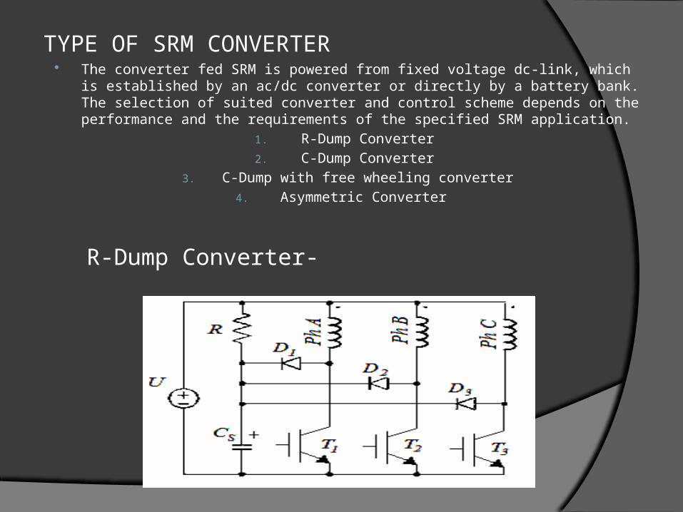
TYPE OF SRM CONVERTER The converter fed SRM is powered from fixed voltage dc-link, which is established by an
ac/dc converter or directly by a battery bank. The selection of suited converter and control scheme depends on the performance and the requirements of the specified SRM application.
1. R-Dump Converter2. C-Dump Converter
3. C-Dump with free wheeling converter4. Asymmetric Converter
R-Dump Converter-
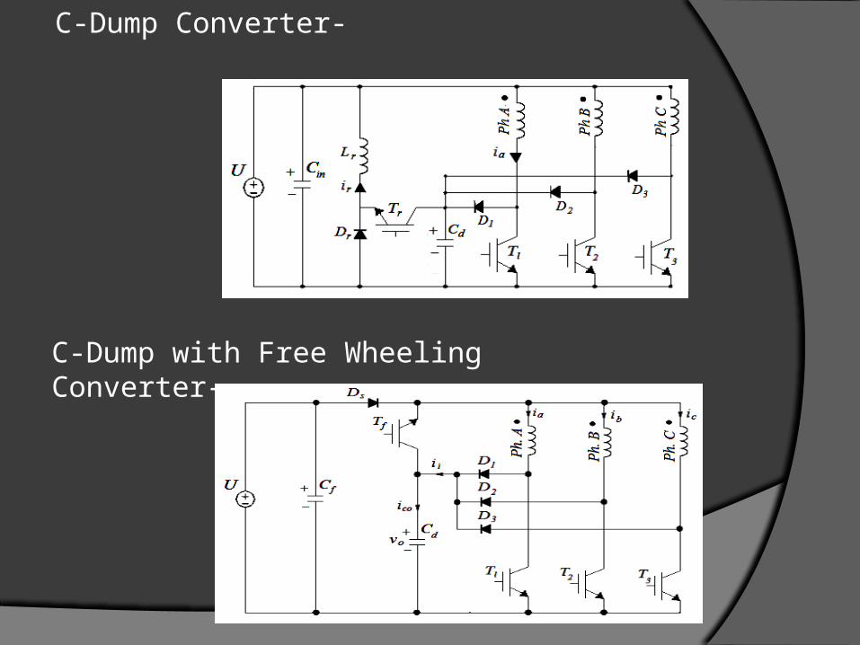
C-Dump Converter-
C-Dump with Free Wheeling Converter-

Asymmetric, Classic, or Conventional Converter -
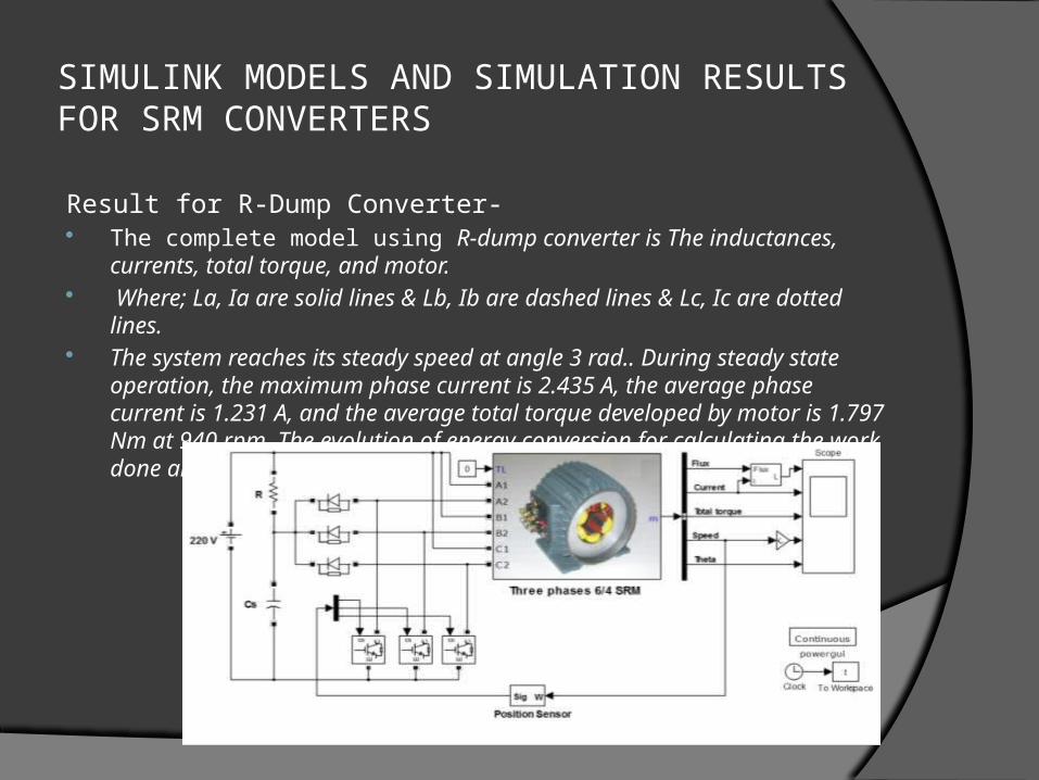
SIMULINK MODELS AND SIMULATION RESULTS FOR SRM CONVERTERS
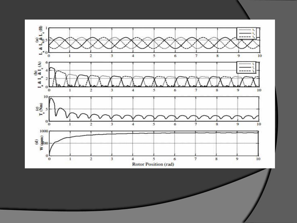
Result for R-Dump Converter- The complete model using R-dump converter is The inductances, currents,
total torque, and motor. Where; La, Ia are solid lines & Lb, Ib are dashed lines & Lc, Ic are dotted
lines. The system reaches its steady speed at angle 3 rad.. During steady state
operation, the maximum phase current is 2.435 A, the average phase current is 1.231 A, and the average total torque developed by motor is 1.797 Nm at 940 rpm. The evolution of energy conversion for calculating the work done and motor average torque can be represented for phase a


Results for C-Dump Converter -The simulation model using C-dump converter is shown in. The simulink results are shown in Fig. The system reaches its steady speed at a step angle about 3 rad. The simulation results during steady state shows that the shape of phase inductance is not distorted. During steady state operation, the maximum phase current is 2.443 A, the average phase current is 0.9053 A, and the average total torque developed by motor is 1.759 Nm at 927 rpm. The evolution of energy conversion for calculating the work done and motor average torque can be represented for phase a by following fig.
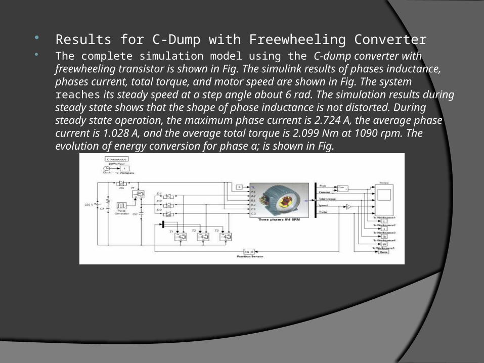
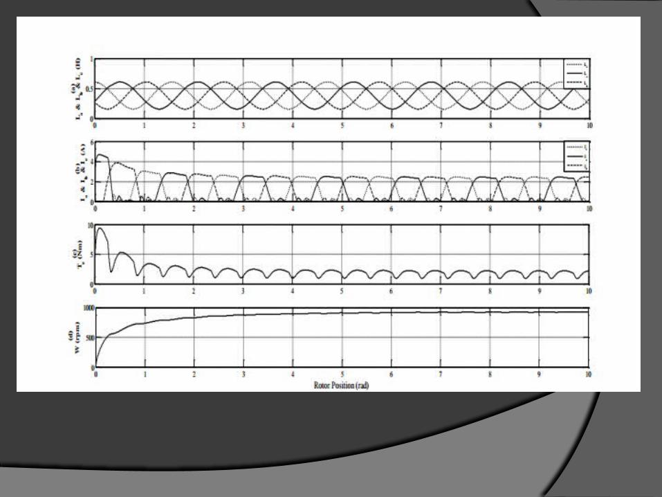
Results for C-Dump with Freewheeling Converter The complete simulation model using the C-dump converter with freewheeling
transistor is shown in Fig. The simulink results of phases inductance, phases current, total torque, and motor speed are shown in Fig. The system reaches its steady speed at a step angle about 6 rad. The simulation results during steady state shows that the shape of phase inductance is not distorted. During steady state operation, the maximum phase current is 2.724 A, the average phase current is 1.028 A, and the average total torque is 2.099 Nm at 1090 rpm. The evolution of energy conversion for phase a; is shown in Fig.

Results for Asymmetric Bridge Converter The complete simulation model using the asymmetric bridge (H-bridge) converter is
shown in Fig. The simulink results of phases inductance, phases current, total torque, and motor speed are shown in Fig. The system reaches its steady speed at a step angle about 5 rad. The simulation results during steady state shows that the shape of phase inductance is not distorted. During steady state operation, the maximum phase current is 2.379 A, the average phase current is 0.953 A, and the average total torque developed by motor is 1.756 Nm at 946 rpm. The evolution of energy conversion for phase a is shown in Fig.


Comparison Between The Simulation Results-
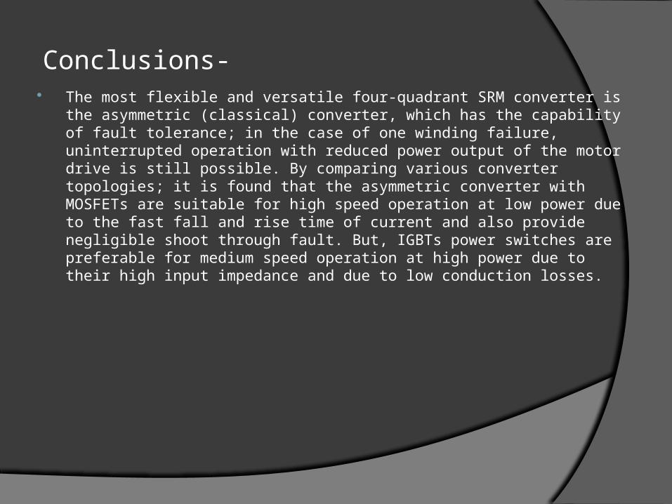
Conclusions- The most flexible and versatile four-quadrant SRM converter is the asymmetric
(classical) converter, which has the capability of fault tolerance; in the case of one winding failure, uninterrupted operation with reduced power output of the motor drive is still possible. By comparing various converter topologies; it is found that the asymmetric converter with MOSFETs are suitable for high speed operation at low power due to the fast fall and rise time of current and also provide negligible shoot through fault. But, IGBTs power switches are preferable for medium speed operation at high power due to their high input impedance and due to low conduction losses.
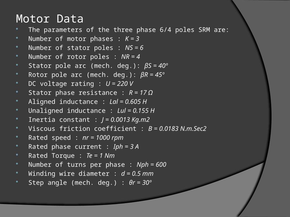
Motor Data The parameters of the three phase 6/4 poles SRM are: Number of motor phases : K = 3 Number of stator poles : NS = 6 Number of rotor poles : NR = 4 Stator pole arc (mech. deg.): βS = 40º Rotor pole arc (mech. deg.): βR = 45º DC voltage rating : U = 220 V Stator phase resistance : R = 17 Ω Aligned inductance : Lal = 0.605 H Unaligned inductance : Lul = 0.155 H Inertia constant : J = 0.0013 Kg.m2 Viscous friction coefficient : B = 0.0183 N.m.Sec2 Rated speed : nr = 1000 rpm Rated phase current : Iph = 3 A Rated Torque : Te = 1 Nm Number of turns per phase : Nph = 600 Winding wire diameter : d = 0.5 mm Step angle (mech. deg.) : θr = 30º

References- T. Wichert, “Design and construction modifications of switched reluctance machines,” Ph.D. thesis,
Warsaw University of Technology, 2008. Y Hasegawa, K. Nakamura, and O. Ichinokura, “Development of a switched reluctance motor made of
permendur,” in Proc. 2nd Int. Symp. on Advanced Magnetic Materials and Applications, Journal of Physics, 2011.
M. T. Lamchich, Torque Control, InTech Publisher, February 10 2011, ch. 8. R. D. Doncker, D. W. J. Pulle, and A. Veltman, Advanced Electrical Drives: Analysis, Modeling, Control,
Springer Press, 2011, ch. 10. E. S. Elwakil and M. K. Darwish, “Critical review of converter topologies for switched reluctance motor
drives,” International Review of Electrical Engineering, vol. 2, no. 1, January-February 2011. J. W. Ahn, J. Liang, and D. H. Lee, “Classification and analysis of switched reluctance converters,”
Journal of Electrical Engineering & Technology, vol. 5, no. 4, pp. 571-579, 2010. Ž. Grbo, S. Vukosavić, and E. Levi, “A novel power inverter for switched reluctance motor drives,” FACTA
Universitatis (NIŠ), Elec. Eng., vol. 18, no. 3, pp. 453-465, December 2005. B. Singh, R. Saxena, Y. Pahariya, and A. R. Chouhan, “Converters performance evaluation of switched
reluctance motor in simulink,” International Journal of Industrial Electronics and Control, vol. 3, no. 2, pp. 89-101, 2011. P. Vijayraghavan, “Design of switched reluctance motors and development of a universal controller for
switched reluctance and permanent magnet brushless DC motor drives,” Ph.D. dissertation, Faculty of the Virginia Polytechnic Institute and State University, Blacksburg, Virginia, November 2001.
R. Krishnan, Switched Reluctance Motor Drives: Modeling, Simulation, Analysis, Design, and Applications, CRC Press 2001.
R. Krishnan, and P. N. Materu, “Analysis and design of a low-cost converter for switched reluctance motor drives,” IEEE Transactions on Industry Applications, vol. 29, no. 2, pp. 320-327, March/April 1993.

THANK YOU


![DAB Converter Based on Unified High-Frequency …...Generally, BDCs include current-fed and voltage-fed converters [6], [7]. In the current-fed BDC, the spike voltage is usually across](https://img.dokumen.tips/doc/110x75/5fd1e3f2a710c80b81223e67/dab-converter-based-on-unified-high-frequency-generally-bdcs-include-current-fed.jpg)