Embed Size (px)
Citation preview
PRESENTATION ON
DEEP BAR & DOUBLE CAGE
ROTORS
PRESENTED BY-Manish SahuEE-5th SEMESTERROLL NO:1013123
Need for Deep-Bar and Double-Cage rotor
Deep-Bar rotors
Torque-Slip relationship
Double-Cage rotors
Equivalent circuit diagram
Applications
Conclusion
What is the need?
Conventional Squirrel Cage motors suffer from the disadvantages of low starting torque because of low rotor resistance.
The starting torque can be increased by using the bar material of higher resistivity.
However high rotor resistance reduces the full-load speed, increases rotor ohmic loss and lower efficiency.
Therefore in order to achieve high starting torque without effecting the efficiency, the rotor resistance is made higher at the time of starting & low under normal operating conditions.
In wound rotor induction motors these conditions are met by connecting external resistance in rotor circuit at the time of starting & resistances are cut out in steps as the motor attains its normal speed.
In squirrel cage motor this is not feasible as the conductors are short-circuited by end rings. In order to attain the above desired conditions following types of rotors are used:-
Deep bar rotor.
Double cage rotor.

Figure below shows a cage rotor with deep and
narrow bars. A bar may be assumed to be made up of number of narrow layers connected in parallel.
It is seen that the top most layer element ‘A’ is linked with minimum leakage
flux and therefore its leakage
inductance is minimum.
On the other hand, the bottom
layer ‘C’ links maximum flux,
therefore its leakage inductance
is maximum.
At starting the rotor frequency is equal to the supply
frequency. The bottom layer element ‘C’ offers more
impedance to the current flow then upper layer ‘A’.
Therefore the maximum current flows through the
top layer and minimum through bottom layer. This
unequal current distribution causes the effective rotor
resistance to increase.
With a high rotor resistance at starting condition, the
starting torque is relatively high & starting current is
low as desired.
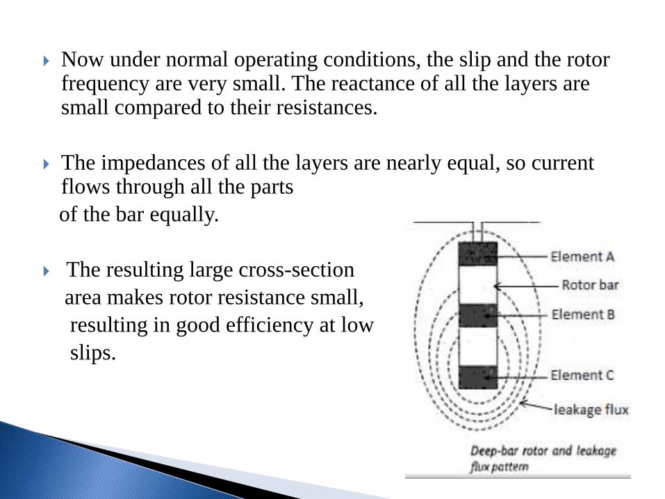
Now under normal operating conditions, the slip and the rotor frequency are very small. The reactance of all the layers are small compared to their resistances.
The impedances of all the layers are nearly equal, so current flows through all the parts
of the bar equally.
The resulting large cross-section
area makes rotor resistance small,
resulting in good efficiency at low
slips.
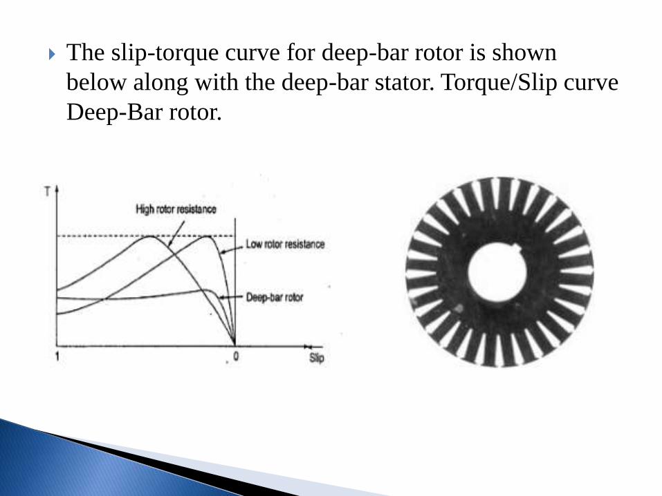
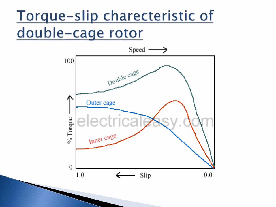
The slip-torque curve for deep-bar rotor is shown
below along with the deep-bar stator. Torque/Slip curve
Deep-Bar rotor.
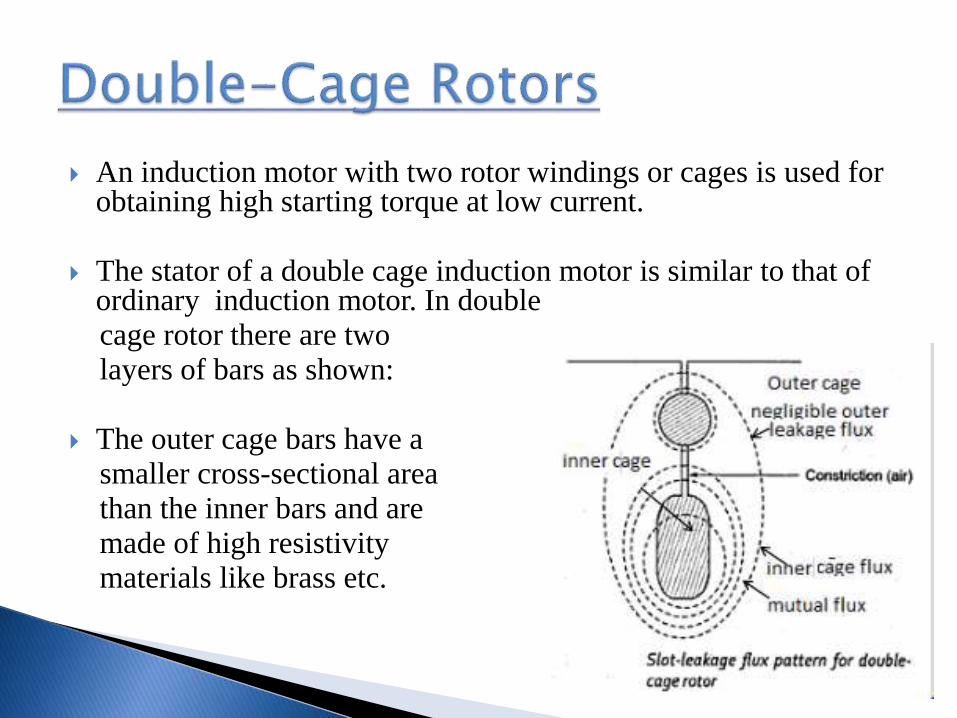
An induction motor with two rotor windings or cages is used for obtaining high starting torque at low current.
The stator of a double cage induction motor is similar to that of ordinary induction motor. In double cage rotor there are two layers of bars as shown:
The outer cage bars have asmaller cross-sectional areathan the inner bars and aremade of high resistivitymaterials like brass etc.
The inner cage bars are made up of low resistance material like copper. Thus the resistance of outer cage is greater than that of inner cage.
There is a slit between the top and bottom slot. This increases premeance for leakage flux around the inner cage bars.
Thus the leakage flux linking the inner cage winding is much larger than that of outer cage. The inner cage winding, therefore has a greater self inductance.
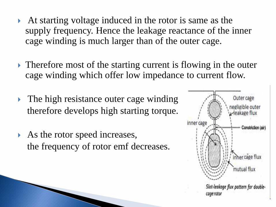
At starting voltage induced in the rotor is same as the supply frequency. Hence the leakage reactance of the inner cage winding is much larger than of the outer cage.
Therefore most of the starting current is flowing in the outer cage winding which offer low impedance to current flow.
The high resistance outer cage winding
therefore develops high starting torque.
As the rotor speed increases,
the frequency of rotor emf decreases.
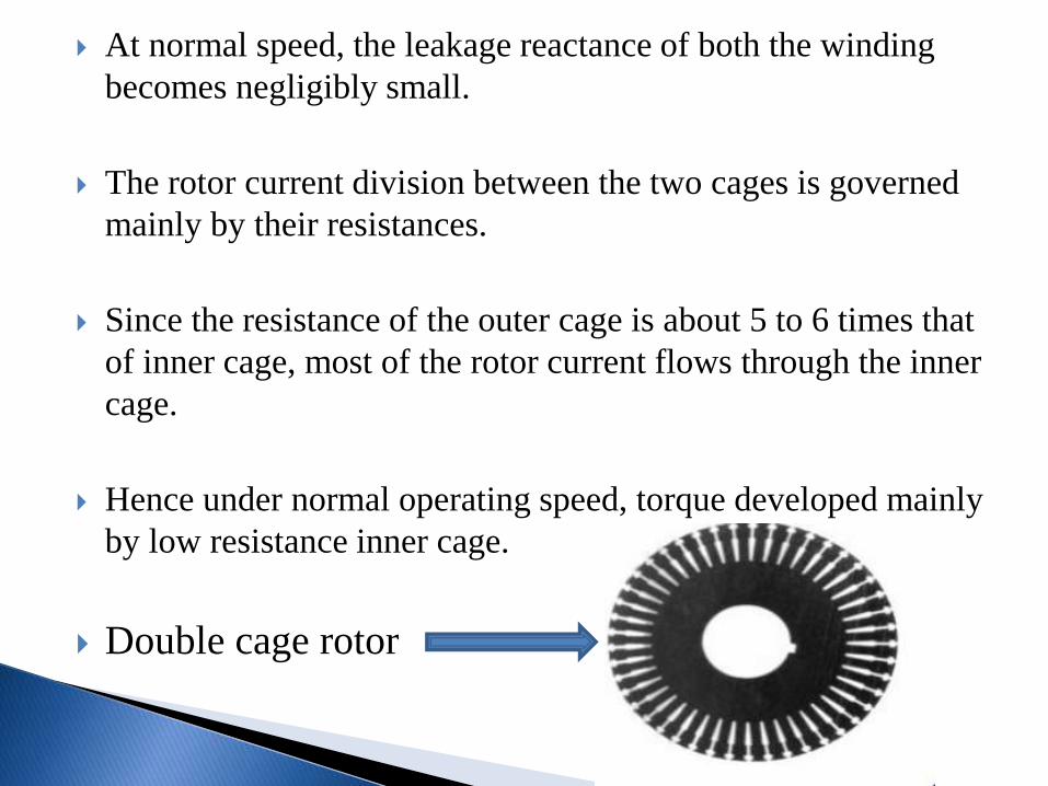
At normal speed, the leakage reactance of both the winding
becomes negligibly small.
The rotor current division between the two cages is governed
mainly by their resistances.
Since the resistance of the outer cage is about 5 to 6 times that
of inner cage, most of the rotor current flows through the inner
cage.
Hence under normal operating speed, torque developed mainly
by low resistance inner cage.
Double cage rotor
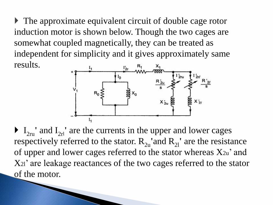
The approximate equivalent circuit of double cage rotor
induction motor is shown below. Though the two cages are
somewhat coupled magnetically, they can be treated as
independent for simplicity and it gives approximately same
results.
I2ru' and I2rl' are the currents in the upper and lower cages
respectively referred to the stator. R2u'and R2l' are the resistance
of upper and lower cages referred to the stator whereas X2u’ and
X2l’ are leakage reactances of the two cages referred to the stator
of the motor.
Applications
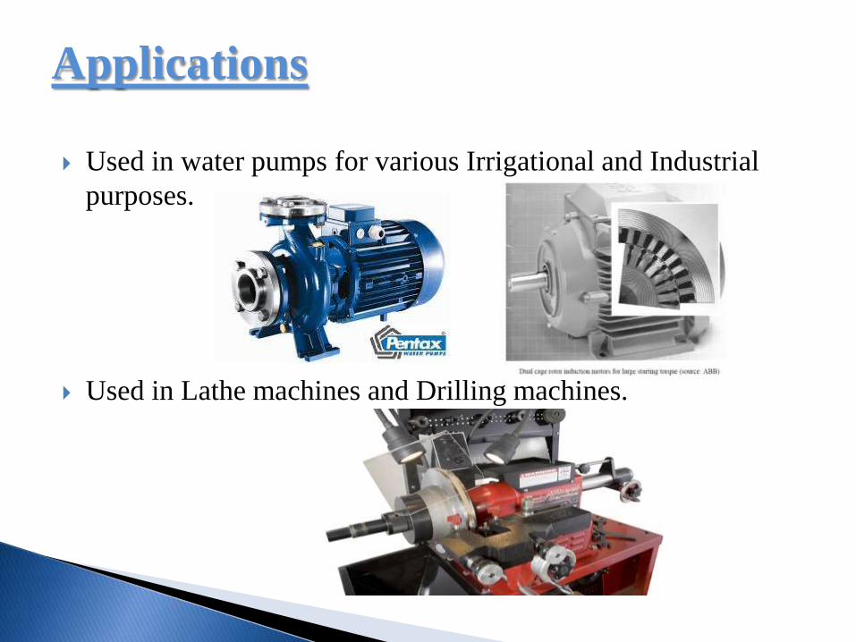
Used in water pumps for various Irrigational and Industrial
purposes.
Used in Lathe machines and Drilling machines.
It is evident by now that for low starting torque requirement, low-cost ordinary squirrel-cage construction is employed.
A deep-bar construction is adopted for higher starting torque applications and double-cage for still higher starting torque needs.
For large size motors with stringent starting torque needs, the most expensive slip-ring construction is used.
I.J. Nagrath and D.P. Kothari,’Electric Machines’, 4th
edition., 2010, Tata McGraw Hill Education Pvt Ltd.
B.R. Gupta & Vandana Singhal, “Fundamentals of Electrical Machines, New Age International, 2009.
http://www.electrical4u.com/squirrel-cage-rotors/(04/09/2014)
http://www.electrical4u.com/squirrel-cage-double-and-deep-bar-rotors/(04/09/2014)
http://www.powerelectricalblog.com/2007/04/construction-of-rotors/induction-machine.html(04/09/2014)