Embed Size (px)
Citation preview
ALL INDIA RADIO, KOTA
submitted by:Jitendra Malav
11BEC0082ECE & 4th year
Introduction• AIR,Kota is situated at Jhalawar Road,Kota (Rajasthan).It started working on 4th
january 1987. Initially there was only 1KW MW transmitter. Programmes arebroadcast mainly in two languages Hindi and Hadoti.1 KW transmitter cover 50 kmand 20 KW transmitter covers 150 km .
• 1)1KW medium wave transmitter
Operating frequency : 1584 KHz
This frequency channel is also called as Chambal chanel of Akashvani Kota. For thischannel many programs are locally produced here in Akashvani Kota studio.Theseprograms may be sent to 20 KW SW transmitter situated in Ummedganj,Kota via STLused for coupling of transmission.
• 2) 20 KW medium wave Transmitter(Ummedganj,Kota)
Operating frequency : 1413 kHz
• This transmitter works on principle of sky wave propagation. It has two operating frequencies because of change in thickness of ionosphere layer. It has very high coverage i.e. programmes are listen all over cities because of its transmission. Its frequency response is almost flat on entire audio range.
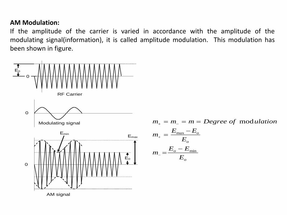
AM Modulation:If the amplitude of the carrier is varied in accordance with the amplitude of themodulating signal(information), it is called amplitude modulation. This modulation hasbeen shown in figure.
o
o
o
o
E
EEm
E
EEm
ulationofDegreemmm
min
max
mod
Emin Emax
E0
E0
0
RF Carrier
Modulating signal
0
0
AM signal
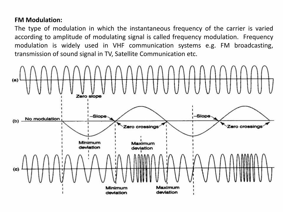
FM Modulation:The type of modulation in which the instantaneous frequency of the carrier is variedaccording to amplitude of modulating signal is called frequency modulation. Frequencymodulation is widely used in VHF communication systems e.g. FM broadcasting,transmission of sound signal in TV, Satellite Communication etc.
ADVANTAGES OF FM OVER AM MODULATION:
1. Amplitude and hence power of FM wave is constant and independent of depth ofmodulation. But in AM, modulation depth determines the transmitted power. Thusadditional energy is not required as modulation is raised.
2. FM is more economical than AM due to following reasons :
(a) It is possible to have Low Level Modulation in FM as the intelligence is in thefrequency variations only and the modulated signal can be passed through class Camplifiers. But since the AM signal contains information in amplitude variations, soonly high level modulation is possible in an AM transmitter
(b) All the transmitted power in FM is useful whereas in AM most of it is in thecarrier which contains no useful information.
(c) Antenna gain is possible in FM due to the reason that directive antennas areused in VHF range where the physical dimensions of the antenna are very easy tomanage.
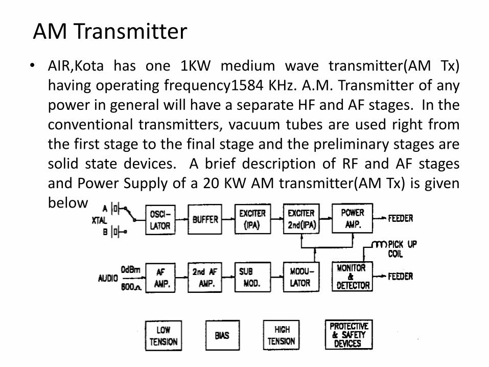
AM Transmitter
• AIR,Kota has one 1KW medium wave transmitter(AM Tx)having operating frequency1584 KHz. A.M. Transmitter of anypower in general will have a separate HF and AF stages. In theconventional transmitters, vacuum tubes are used right fromthe first stage to the final stage and the preliminary stages aresolid state devices. A brief description of RF and AF stagesand Power Supply of a 20 KW AM transmitter(AM Tx) is givenbelow
• RF Section RF section consists of crystal oscillator, buffer, intermediate power Amplifier,Exciter and power amplifier. The crystal oscillator with buffer stage isgenerally kept together and is shielded by a metal cover to isolate from othercircuits.
• IPA Stage This stage employs an indirectly heated beam power tube BEL 25 and itoperates as a class C amplifier.
• Exciter
This stage is operated as a class - C amplifier. This stage is modulated about 10 to 20%. A small secondary tap from the modulation transformer supplies the necessary audio and super-imposes on the DC Plate supply. When the triodes are anode modulated, the grid must be overdriven in the carrier condition in order that the drive level will be adequate to sustain the peak anode current at 100% modulation.
• Power Amplifier StageThis is a class - C power amplifier obtaining the required output by means ofthree parallel connected forced air cooled, directly heated triode tubes typeBEL 3000. As a triode tube is used in this stage, neutralization technique isadopted to neutralize, the grid-plate capacitance.
• AF Circuits
The audio frequency amplifier consists of two voltage amplifiers, a cathodefollower which serves as a driver to the modulator and the modulator is aclass B push pull power Amplifier.
• First and Second AF Amplifier Stages
This stage is operated as a class A push pull connected amplifier employingtwo indirectly heated pentode type 4P55 or its near equivalent whichprovides about 30 dB gain. The output from the first AF stage is coupled tothe second stage through the coupling condensers. Plate supply is obtainedfrom the neutral of the HT. (Plate) Transformer.
• Sub Modulator StageThis stage employs two 4B 85 (or its equivalent with modifications) inpush-pull mode to excite the modulator. The sub-modulator is acathode follower. As the grid current flows in the modulator tube, theinput impedance varies widely with different input levels and hence acathode follower which possesses low output impedance, very smallnon linear distortion for load impedance variations and goodfrequency and phase shift characteristics is used. The DC. potential ofthe cathodes of sub-modulator and the grid of the modulator stagesare kept nearly at the same negative voltage of about 200 volt.
• Modulator AmplifierThis is the final stage audio frequency power amplifier which suppliesthe RF power amplifier, the required modulating power. The HT andthe superimposed audio signals are connected to the plate of the PAvalves. It may be noted that the negative feedback Network isconnected in the primary of the modulation transformer.
• Power Supply Filament Supply
For PA and modulator valves, there is a separate filament transformers with centre taparrangement. The centre tap will be grounded through metering current shuntresistance for the measurement of a cathode currents and an overload coils in parallelwith a resistance.
Low Tension : 3 phase 220 V AC is stepped up to 3 phase 520 V AC using aDelta/Star connected transformer. It is rectified using silicon diodes and filtered usingL C components. It gives DC voltage to the following.1. Plate and screen of 1st AF, 2nd AF, oscillator and Buffer.2. Screen grid of sub modulator3. Sub modulator plate and IPA plate.
Bias : 3 phase 400 V AC is stepped up to 3 phase 470 V using Delta/Starconnected transformer and rectified using silicon diodes in two sets SE 2 and SE3 andfiltered using L-C components. SE 2 output supply is connected to the cathode Bias ofsub modulator. The out put of SE 3 is connected to control grid of Exciter and Grid ofP.A.
High Tension : 3 phase 400 V AC is stepped up to 2300 V 3 phase and rectifiedusing silicon diodes assembly SE4 and filtered using L-C components. Full HT issupplied to plate of modulator and PA valves. The filtered DC from the star point ofthe HT transformer is connected to the plate of 2nd AF and plate and screen grid ofExciter.
STUDIO CHAIN IN A TYPICAL AIR STATION:
• The broadcast of a programme from source to listener involves use ofstudios, microphones, announcer console, switching console, telephonelines / STL and Transmitter. Normally the programmes originate from astudio centre located inside the city/town for the convenience of artists.The programme could be either “live” or recorded”.
• Studio CentreThe Studio Centre comprises of one or more studios, recording and dubbingroom, a control room and other ancilliary rooms like battery room, a.c.rooms, switch gear room, DG room, R/C room, service room, waiting room,tape library, etc. . The studio centres in AIR are categorised as Type I, II, IIIand IV. The number of studios and facilities provided in each type aredifferent. For example a type I studio has a transmission studio, music studiowith announcer booth, a talks studio with announcer booth, onerecording/dubbing room and a Read Over Room. Type II has one additionaldrama studio.
A simplified block schematic showing the different stages is given in Fig.
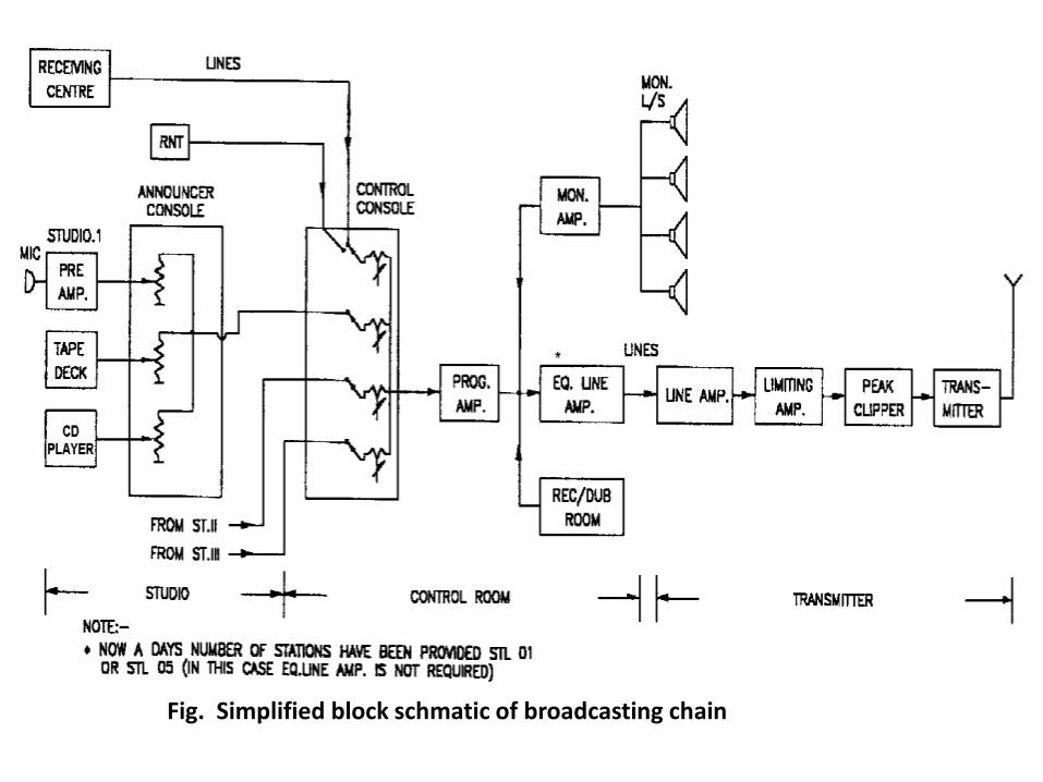
Fig. Simplified block schmatic of broadcasting chain
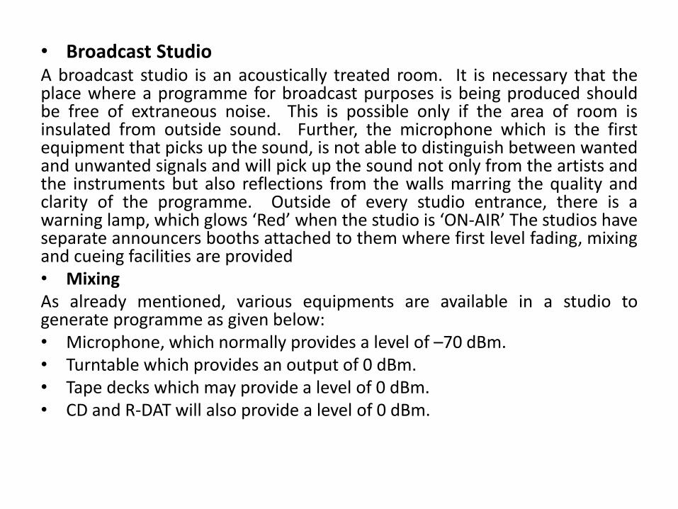
• Broadcast StudioA broadcast studio is an acoustically treated room. It is necessary that theplace where a programme for broadcast purposes is being produced shouldbe free of extraneous noise. This is possible only if the area of room isinsulated from outside sound. Further, the microphone which is the firstequipment that picks up the sound, is not able to distinguish between wantedand unwanted signals and will pick up the sound not only from the artists andthe instruments but also reflections from the walls marring the quality andclarity of the programme. Outside of every studio entrance, there is awarning lamp, which glows ‘Red’ when the studio is ‘ON-AIR’ The studios haveseparate announcers booths attached to them where first level fading, mixingand cueing facilities are provided• MixingAs already mentioned, various equipments are available in a studio togenerate programme as given below:• Microphone, which normally provides a level of –70 dBm.• Turntable which provides an output of 0 dBm.• Tape decks which may provide a level of 0 dBm.• CD and R-DAT will also provide a level of 0 dBm.
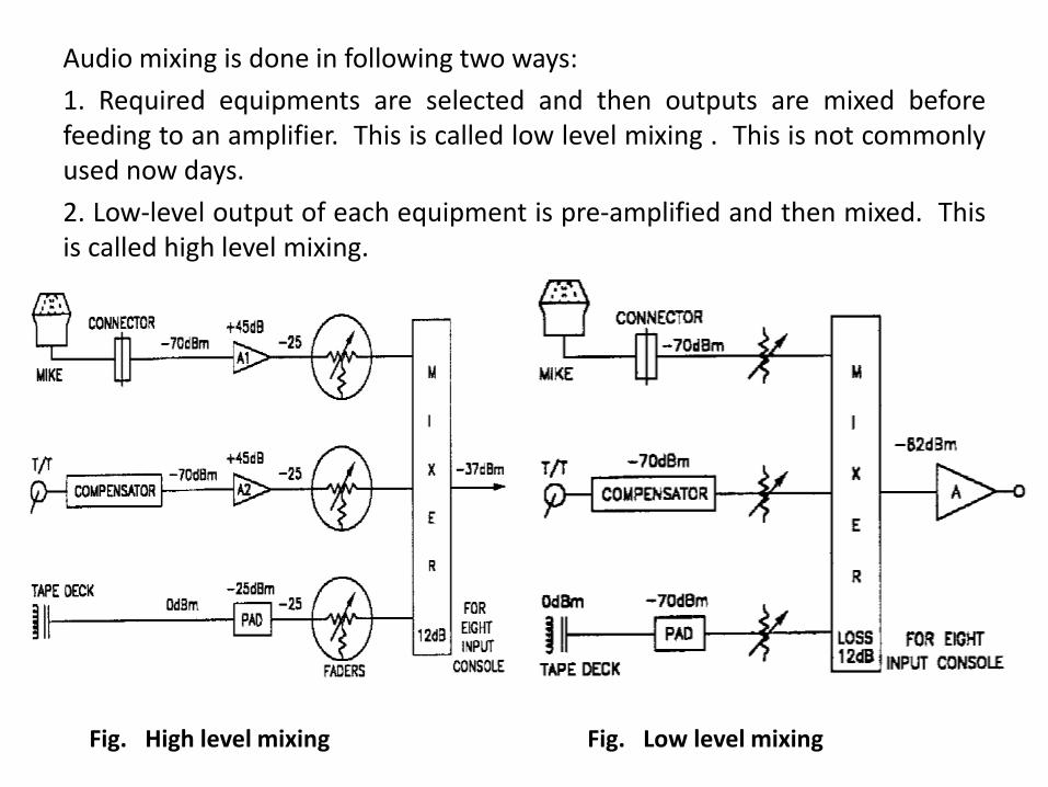
Audio mixing is done in following two ways:
1. Required equipments are selected and then outputs are mixed beforefeeding to an amplifier. This is called low level mixing . This is not commonlyused now days.
2. Low-level output of each equipment is pre-amplified and then mixed. Thisis called high level mixing.
Fig. High level mixing Fig. Low level mixing
• In low level mixing, there is signal loss of about 10 to 15 dB in mixingcircuits. Therefore, the S/N ratio achieved in low level mixing is 35 to 40dB only.
• High level mixing system requires one pre-amplifier in each of the lowlevel channels but ensures a S/N of better than 50 dB. All India Radioemploys High level mixing.
Announcer ConsoleMost of the studios have an attached booth, which is called transmissionbooth or Announcer booth or play back studio. This is also acousticallytreated and contains a mixing console called Announcer Console. TheAnnouncer Console is used for mixing and controlling the programmes thatare being produced in the studio using artist microphones, tape playbackdecks and turn tables/CD players. This is also used for transmission ofprogrammes either live or recorded. The technical facilities provided in atypical announcer booth, besides an Announcer Console are one or twomicrophones for making announcements, two turn tables for playing thegramophone records and two playback decks or tape recorders for recordedprogrammes on tapes. Recently CD and Rotary Head Digital Audio TapeRecorder (R-DAT) are also included in the Transmission Studio.
• Control Room:For two or more studios set up, there would be a provision for furthermixing which is provided by a control console manned by engineers.Such control console is known as switching console. Broad functions ofswitching console in control room are as follows:• Switching of different sources for transmission like News, O.Bs.
other satellite based relays, live broadcast from recording studio.• Level equalisation and level control.• Quality monitoring.• Signalling to the source location.• Communication link between control room and different studios.• Swicthing ConsoleThis switching console has been specially designed for broadcastapplications keeping in view the necessity for high reliability andcontinuous operation. The design of this Console has been evolvedafter close interaction between the P&D Unit of AIR, ER & DC and M/s.Keltron.
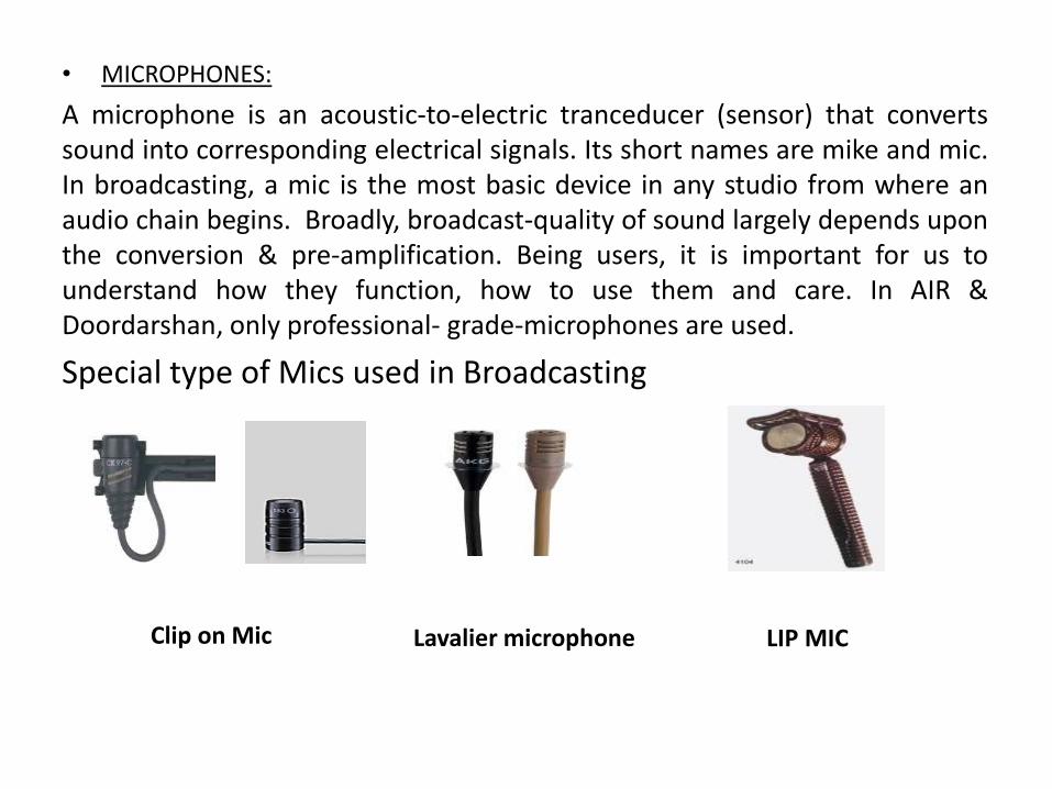
• MICROPHONES:
A microphone is an acoustic-to-electric tranceducer (sensor) that convertssound into corresponding electrical signals. Its short names are mike and mic.In broadcasting, a mic is the most basic device in any studio from where anaudio chain begins. Broadly, broadcast-quality of sound largely depends uponthe conversion & pre-amplification. Being users, it is important for us tounderstand how they function, how to use them and care. In AIR &Doordarshan, only professional- grade-microphones are used.
Special type of Mics used in Broadcasting
Clip on Mic Lavalier microphone LIP MIC
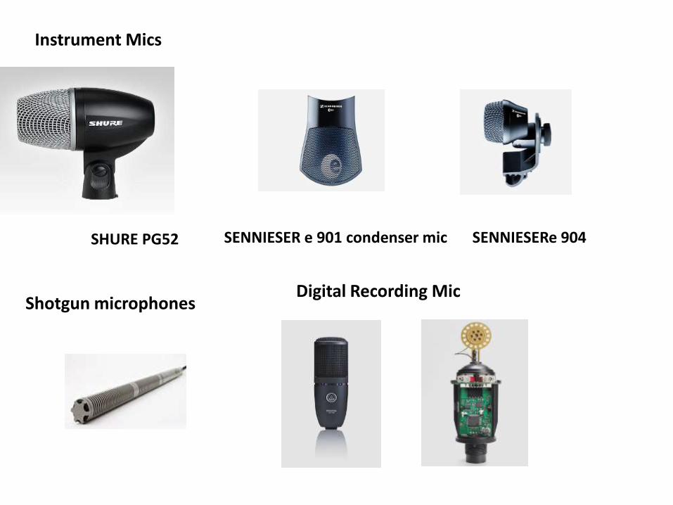
Instrument Mics
SHURE PG52 SENNIESER e 901 condenser mic SENNIESERe 904
Shotgun microphonesDigital Recording Mic
HDBR(HARD DISK BASED RECORDING) SYSTEMThe computer system deals mainly with texts and digits. These texts anddigits are in digital form and are recorded on the hard disk of the computer.So, if the analog audio or video is converted into digital form, it can berecorded on the hard disk of the computer. Then the computer canmanipulate the audio/video in the similar way as it manipulates texts anddigits. This is what is known as hard disk based recording system
• There are two types of hard disk based (audio) recording system :
1. Dedicated system and
2. Networked Hard Disk Based System
• Dedicated System
In dedicated system, there is only one computer terminal for recording or play. This is mainly used for editing purpose with a special key board (edit controller).
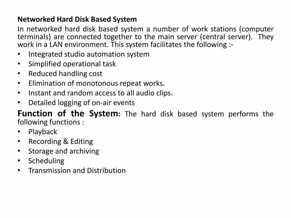
Networked Hard Disk Based SystemIn networked hard disk based system a number of work stations (computerterminals) are connected together to the main server (central server). Theywork in a LAN environment. This system facilitates the following :-• Integrated studio automation system• Simplified operational task• Reduced handling cost• Elimination of monotonous repeat works.• Instant and random access to all audio clips.• Detailed logging of on-air events
Function of the System: The hard disk based system performs thefollowing functions :• Playback• Recording & Editing• Storage and archiving• Scheduling• Transmission and Distribution
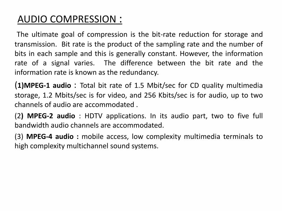
AUDIO COMPRESSION :The ultimate goal of compression is the bit-rate reduction for storage and
transmission. Bit rate is the product of the sampling rate and the number ofbits in each sample and this is generally constant. However, the informationrate of a signal varies. The difference between the bit rate and theinformation rate is known as the redundancy.
(1)MPEG-1 audio : Total bit rate of 1.5 Mbit/sec for CD quality multimedia
storage, 1.2 Mbits/sec is for video, and 256 Kbits/sec is for audio, up to twochannels of audio are accommodated .
(2) MPEG-2 audio : HDTV applications. In its audio part, two to five fullbandwidth audio channels are accommodated.
(3) MPEG-4 audio : mobile access, low complexity multimedia terminals tohigh complexity multichannel sound systems.
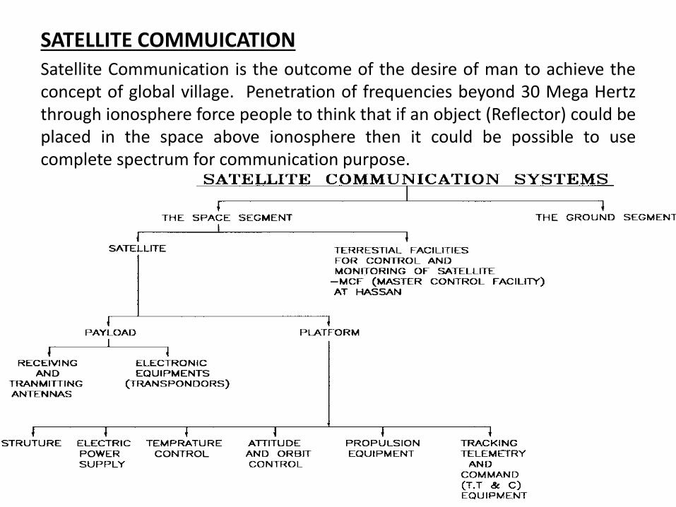
SATELLITE COMMUICATIONSatellite Communication is the outcome of the desire of man to achieve theconcept of global village. Penetration of frequencies beyond 30 Mega Hertzthrough ionosphere force people to think that if an object (Reflector) could beplaced in the space above ionosphere then it could be possible to usecomplete spectrum for communication purpose.
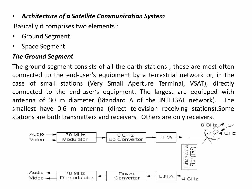
• Architecture of a Satellite Communication System
Basically it comprises two elements :
• Ground Segment
• Space Segment
The Ground Segment
The ground segment consists of all the earth stations ; these are most oftenconnected to the end-user’s equipment by a terrestrial network or, in thecase of small stations (Very Small Aperture Terminal, VSAT), directlyconnected to the end-user’s equipment. The largest are equipped withantenna of 30 m diameter (Standard A of the INTELSAT network). Thesmallest have 0.6 m antenna (direct television receiving stations).Somestations are both transmitters and receivers. Others are only receivers.
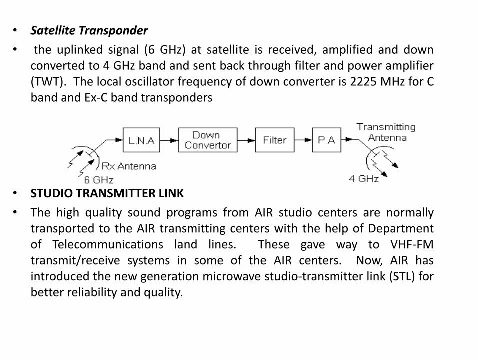
• Satellite Transponder
• the uplinked signal (6 GHz) at satellite is received, amplified and downconverted to 4 GHz band and sent back through filter and power amplifier(TWT). The local oscillator frequency of down converter is 2225 MHz for Cband and Ex-C band transponders
• STUDIO TRANSMITTER LINK
• The high quality sound programs from AIR studio centers are normallytransported to the AIR transmitting centers with the help of Departmentof Telecommunications land lines. These gave way to VHF-FMtransmit/receive systems in some of the AIR centers. Now, AIR hasintroduced the new generation microwave studio-transmitter link (STL) forbetter reliability and quality.
• Studio Transmitter Link - Transmitter (STL-TX)• It consists : A single audio input transformer which splits the audio input
into two equal audio outputs .
• The base band unit consisting of a music amplifier , and a base bandinterface unit which is a 15 kHz low pass filter.
• The radio frequency unit which generates the carrier, FM modulates andgenerates microwave (RF) power.
• An antenna change over unit which selects one of the RF outputs forfeeding to the antenna.
• A low loss cable connected to a microwave dish antenna at suitable heightabove the ground.
• Two identical dc power supplies
• One each of logic and parameter control card which selects one of the RFoutputs to be connected to the transmitting antenna
• Studio Transmitter Link – Receiver (STL-RX)• The STL receiver essentially consists sections similar to STL transmitter.
• 2 m dia microwave dish antenna mounted on a tower of suitable heightand a low loss cable connects the received RF power into the receivingsystem.
• Antenna filter and RF hybrid divider unit.
• The radio frequency receiver unit which recovers the base band signalfrom the modulated RF carrier.
• A single audio line transformer which provides the audio output.
• Two identical DC power supply units.
• One each of Logic and parameter control card which selects one of theaudio outputs
The receiver has a threshold sensitivity of the order of –80 dBm. But it isadvisable to use the system at –40 to –60 dBm.
SAFETY MEASURES• FIRE EXTINGUISHERS
• Soda Acid Type
• Chemical Foam Type
• Carbon-tetra-chloride
• CO2 Gas Type ,Sand bucket
Earthing• The term earthing means connecting the neutral point of a supply
system or non-current carrying parts of electrical apparatus to thegeneral mass of earth in such a manner that at all times animmediate discharge of electrical energy takes place withoutdanger.
• The function of earthing is two fold
• It is for ensuring that no current carrying conductor rises to apotential with respect to general mass of earth than its designedinsulation.
• It is for the safety of the human beings from the electric shocks.
• CONCLUSIONS• The training at RADIO broadcasting station indeed adds
knowledge of wide concept of wireless communicationespecially for broadcasting purpose. The study ofoperation and maintenance of studio consoles and themedium wave high power transmitter helps in relatingtheoretical concept of communication with thepractical.
• Also, the measuring instrument used there give betterunderstanding of the monitoring and control of audiosignal as well as modulated signal" It was verysatisfactory period of training where I gained veryuseful overall training. It also provided me anopportunity to develop myself as an engineer withCompetitive edge.