Embed Size (px)
Citation preview

Presentation
ON
Acoustic Emission & its Application in Diagnostic
INDIAN INSTITUTE OF TECHNOLOGY, DELHI
Presented By:
Rajeev Ranjan
(2005JIT2527)

Outline of Presentation
• Introduction
• Principle
• Definitions
• Application
• Case Studies
• Advantages & Limitations
• Conclusion

INTRODUCTION
• Acoustic Emission
• Diagnostics
Acoustic emissions (AEs) are the stress waves produced by the sudden internal stress of the material caused by the changes in internal structure. The frequency of the stress waves emitted is normally in the range 30 kHz to 1 MHz.
An important strategy for advanced, cost-effective, maintenance. It uses an indicator of equipment and component health as a trigger for maintenance action. This means that maintenance staff are engaged in inspection and monitoring tasks rather than repair and replacement of worn-out or defective components.

PRINCIPLE
Source: AE Tech Technology, France

DEFINITIONS
• Threshold
• Event Count
• Peak Amplitude
• Rise Time
• Event Duration

APPLICATIONS1. Pressure equipment: A reliable and standard
method of non-destructive testing for pressure vessels. AE is used to monitor flaws, corrosion, and leakage in pressure vessels, LPG, tanks, piping systems, steam generators.
Source: Enviroacoustics S.A, Greece

2. Aircraft and aerospace: aerospace structures, wings, bulkhead, fuel tanks, Rocket engine, real time monitoring;
3. Petrochemical and chemical: storage tanks, reactor vessels, offshore and onshore platforms, drill pipe, pipeline;
4. Marine: corrosion, composite shell, engine and power plant;
APPLICATIONS

5. Civil engineering: bridges, dams, suspension cable bridges, concrete structure reinforced by composite;
6. Research and development: acoustic emission is a good technique to monitor and study the damage in materials and their mechanical properties (new materials, smart materials, Shape memory alloys (SMA)).
APPLICATIONS

Application in Composite

Seagate Drive Quantum Drive
Application in Hard Disk Drive

Case Study I- Crack Detection in Rail Track(Funded by Canadian National Railway)
aK mKAdN
da
nKAnP )(
nKBN
P(n) = Acoustic emission parameter
N = AE Count rate

Scanning electron micrograph showing crack initiatio
n
Case Study I- Crack Detection in Rail Track
Four rail steel samples were tested for fatigue with load ratio 0.3 and frequency 30 cycles per second.
When the specimens counter tested in SEM substantial onset of crack growth was found. The size of these cracks detected was as small as 0.009 mm and initiated from elongated inclusions.

Case Study II- Detection of leak in Nuclear Plant Check Valve
Acoustic emission technique was used to detect disk wear failures and foreign object failures among various failure modes of the check valve.

Therefore, the backward leakage occurs through the not fully closed section in the check valve. The idea of this study is based on the detection of the acoustic wave originating from those backward leakages with acoustic emission technique.
Disk wear mean a disk was worn due to some flaw on the surface, so the backward leakage is induced through the flaw. Also, when the foreign object is, inserted between the disk and housing of a check valve, the disk is not fully closed.
Case Study II- Detection of leak in Nuclear Plant Check Valve


• Comparing the disc wear and foreign object failure modes, the frequency range of the leak signals are significantly different.
• The peak frequencies in all the disk wear failures are about 150 and 225 kHz and those in all the foreign object failures are about 100 and 150 kHz. The peak frequency (150 kHz) is similar in any failure condition.
• So, the frequencies of 225 and 100 kHz can be used as alternatives to distinguish failure modes such as a disk wear and a foreign object.
Results:Case Study II- Detection of leak in Nuclear Plant Check Valve

Case Study III- Life Estimation
Damage evaluation in two pilasters (P1 & P2) sustaining a viaduct along an Italian highway was done.
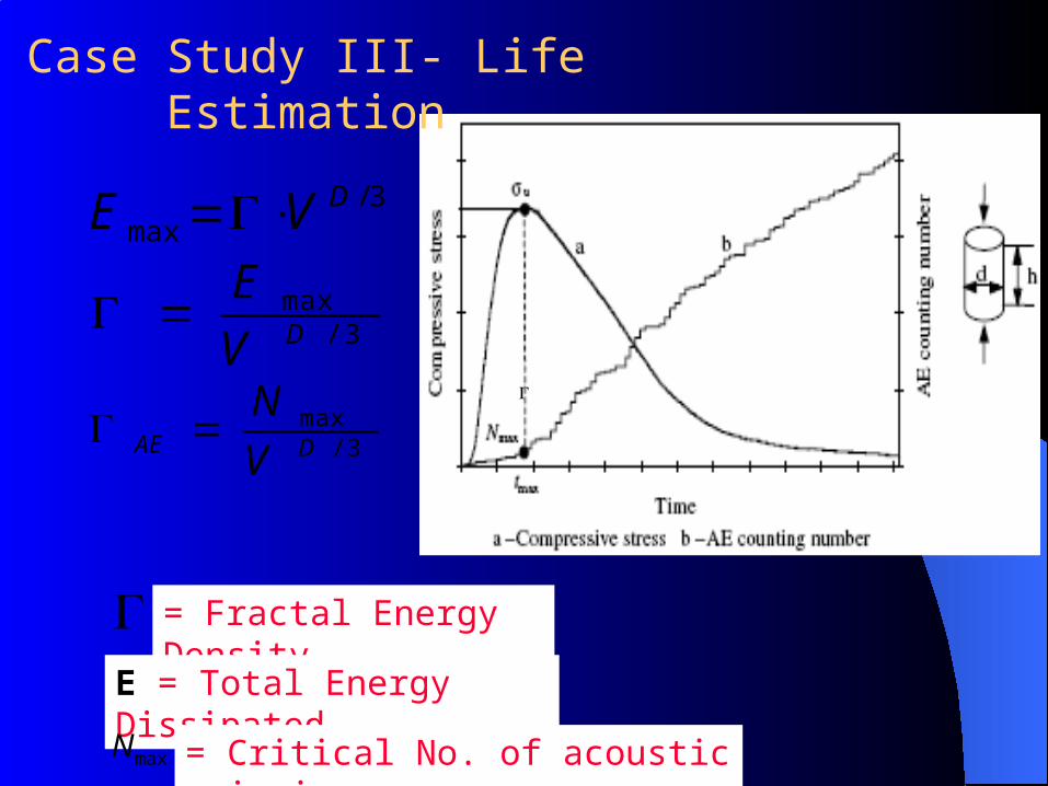
Case Study III- Life Estimation
3/max
DVE
3/maxDV
E
3/maxDAE V
N
= Fractal Energy Density
E = Total Energy Dissipated
maxN = Critical No. of acoustic emission

3/
maxmax
D
rr V
VNN
maxmax N
N
E
E
t
t
t
max
Result: The life time for pillar P1 & P2 obtained 2.4 & 3.4 years respectively considering the time origin from the instant in which the specimen has been drilled.
The damage level of structure can be obtained from AE data of a reference specimen extracted from structure and tested up to rupture.
= Damage Level
Case Study III- Life Estimation

Case Study IV- Diagnosis of Osteoporosis
• Osteoporosis is related to degradation of bone.
• The bone density decreases and becomes weaker.
• There is no other diagnostics tool that can detect osteoporosis in early stages.
• Acoustic emission was successfully used in diagnosing osteoporosis in early stage.

Case Study IV- Diagnosis of Osteoporosis
• Extra attention paid to specimen preparation.
• Two set of specimen are prepared:
- one of normal density & other with low density.
• It was ensured that all the specimens are of uniform dimension and no defect was introduced during machining process.
• The three point bending test was performed in a constant strain rate machine with load rate 0.5` per minute.

Case Study IV- Diagnosis of OsteoporosisSignificant deviation of low density specimen curve from the normal density curve takes place above a certain minimum value of central load.
The variation of emission count with central load suggests that acoustic emission may be used as a diagnostic tool for bone density & crack detection.

ADVANTAGES
• Real time monitoring in service structures • Cost reduction • Time reduction • Defect localization • High sensitivity
• Global structures monitoring • Control of non accessible zones • No intentional injection of an acoustic signal into the
component under test are needed • Can be used with other destructive and non-destructive
techniques.

LIMITATIONS
• AE sensor has to be closed to its source otherwise the signal the originating from defective component will suffer sever attenuation and reflection before reaching to the sensor.
• Service environments are generally very noisy, and the AE signals are usually very weak. Thus, signal discrimination and noise reduction are very difficult.
• AE systems can only estimate qualitatively how much damage is in the material and approximately how long the
components will last. So, other NDE methods are still needed to do more thorough examinations and provide quantitative results.

Conclusion
• Acoustic emission is a very effective low cost diagnostic technique.
• It is a continuously developing multidiscipline and is now focus of research & application based studies.
• With accelerated growth in intelligent information, sensor and data acquisition technologies a healthy growth in application of AE in engineering,
manufacturing, processing and medical sector is expected.

Thank You

Set Up for Acoustic Emission Testing at ITMMEC
Designed as a part of M.Tech Project by -Mr. Akhil Agarwal (NTPC)