Embed Size (px)
Citation preview
Design and Metallurgy of Weld Joints (MEM-510)
1 - 1
Metallurgy of Weld Joints
Dr. Chaitanya Sharma
Welding Metallurgy
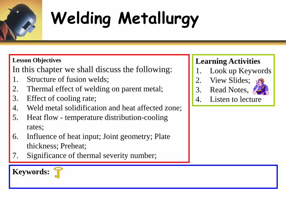
Lesson Objectives
In this chapter we shall discuss the following:1. Structure of fusion welds;
2. Thermal effect of welding on parent metal;
3. Effect of cooling rate;
4. Weld metal solidification and heat affected zone;
5. Heat flow - temperature distribution-cooling
rates;
6. Influence of heat input; Joint geometry; Plate
thickness; Preheat;
7. Significance of thermal severity number;
Learning Activities
1. Look up Keywords
2. View Slides;
3. Read Notes,
4. Listen to lecture
Keywords:

What Is Metallurgy ?
• The science of joining metals by welding is closely relates tothe field of metallurgy.
• Metallurgy involves science of:– Producing metals from ores,
– Making and compounding alloys,
– Metal reactions, Heat treatment,
– Steel making and
– Processing of metals e.g. Forging, Foundry etc.
• Welding metallurgy can be considered a special branch,since reaction times are very small (minutes to fraction ofseconds), while in other branches reactions are large (h-m).
• Welding metallurgy deals with the interaction of differentmetals and interaction of metals with gases and chemicalsof all types.
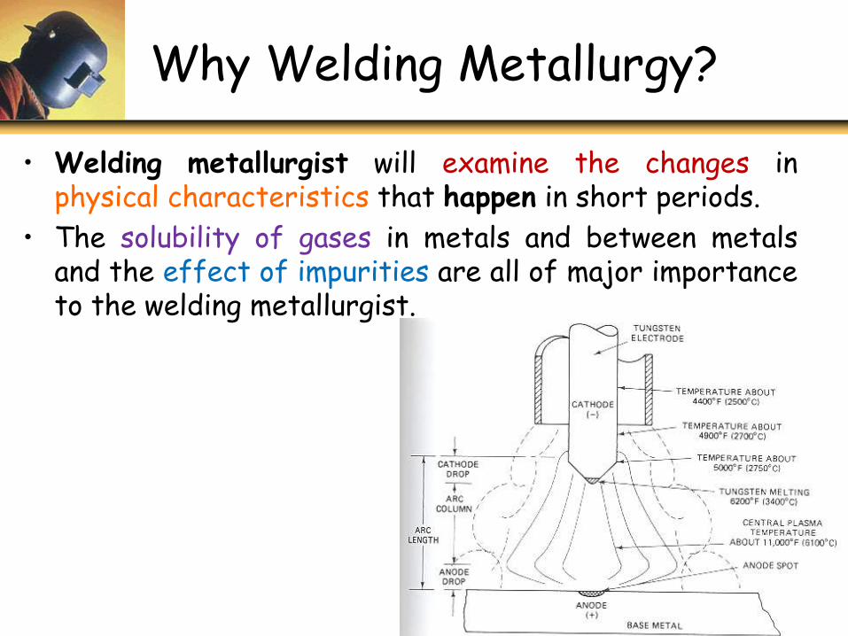
Why Welding Metallurgy?
• Welding metallurgist will examine the changes inphysical characteristics that happen in short periods.
• The solubility of gases in metals and between metalsand the effect of impurities are all of major importanceto the welding metallurgist.
1 - 4
Basic Structure of Fusion Welds
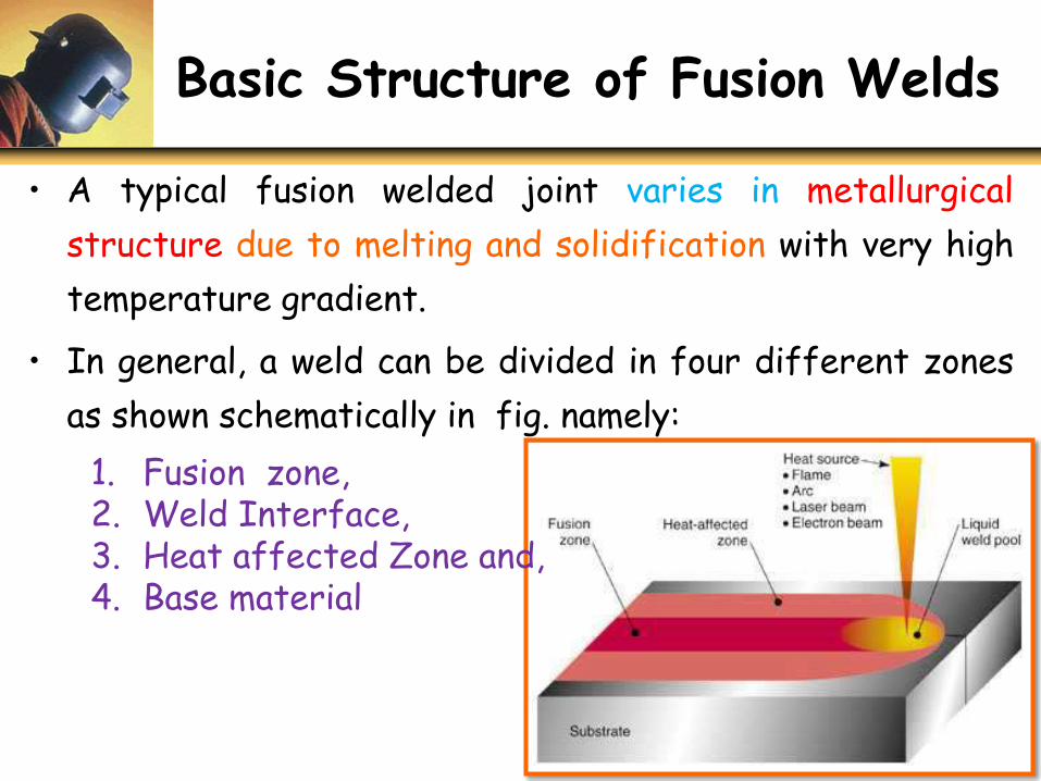
• A typical fusion welded joint varies in metallurgical
structure due to melting and solidification with very high
temperature gradient.
• In general, a weld can be divided in four different zones
as shown schematically in fig. namely:
1. Fusion zone,2. Weld Interface,3. Heat affected Zone and,4. Base material
Structure of Fusion Weld Joints
• The fusion zone (FZ) can be characterized as amixture of completely molten base metal (and fillermetal if consumable electrodes are in use) with highdegree of homogeneity where the mixing is primarilymotivated by convection in the molten weld pool.
• The main driving forces for convective heat transferand resulting mixing of molten metal in weld pool are:(1) Buoyancy force,
(2) Surface tension gradient force,
(3) Electromagnetic force,
(4) Friction force.
Structure of Fusion Weld Joints continued…
• The weld interface, (or mushy zone), is a narrow zone consistingof partially melted base material which has not got anopportunity for mixing. This zone separates the fusion zone andheat affected zone.
• The heat affected zone (HAZ) is the region that experiences apeak temperature that is well below the solidus temperaturewhile high enough that can change the microstructure of thematerial and mechanical properties also change in HAZ.
• The amount of change in microstructure in HAZ depends on theamount of heat input, peak temp reached, time at the elevatedtemp, and the rate of cooling.
• The unaffected base metal zone surrounding HAZ does notundergo any change in microstructure and is likely to be in a stateof high residual stress, due to the shrinkage in the fusion zone.
1 - 7
Various Regions In Fusion Weld & Corresponding Phase Diagram
Dif
fere
ntzo
nes
in a
ste
elw
eld
vis-
à-vi
s Ir
on-C
arbon
equ
ilib
rium
dia
gram
1 - 8
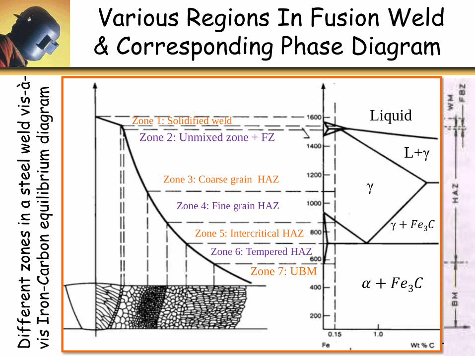
Zone 7: UBM
Zone 6: Tempered HAZ
Zone 5: Intercritical HAZ
Zone 4: Fine grain HAZ
Zone 3: Coarse grain HAZ
Zone 2: Unmixed zone + FZ
Zone 1: Solidified weld
γ
𝛼 + 𝐹𝑒3𝐶
γ+ 𝐹𝑒3𝐶
L+γ
Liquid
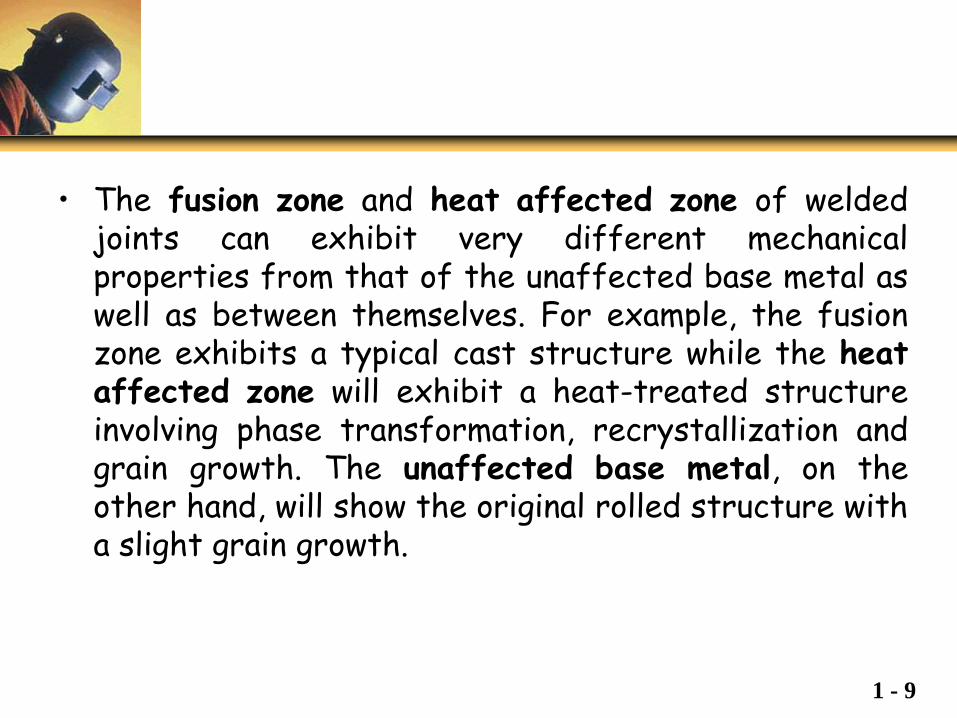
• The fusion zone and heat affected zone of weldedjoints can exhibit very different mechanicalproperties from that of the unaffected base metal aswell as between themselves. For example, the fusionzone exhibits a typical cast structure while the heataffected zone will exhibit a heat-treated structureinvolving phase transformation, recrystallization andgrain growth. The unaffected base metal, on theother hand, will show the original rolled structure witha slight grain growth.
1 - 9
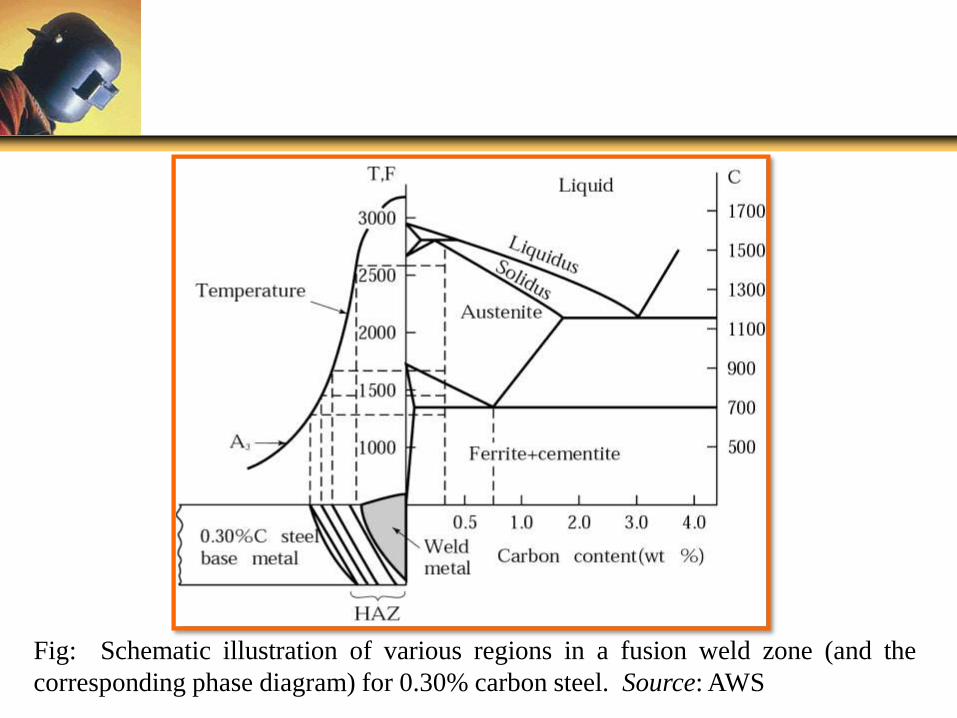
Fig: Schematic illustration of various regions in a fusion weld zone (and the
corresponding phase diagram) for 0.30% carbon steel. Source: AWS
Weld Joint Structure
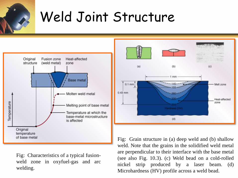
Fig: Characteristics of a typical fusion-
weld zone in oxyfuel-gas and arc
welding.
Fig: Grain structure in (a) deep weld and (b) shallow
weld. Note that the grains in the solidified weld metal
are perpendicular to their interface with the base metal
(see also Fig. 10.3). (c) Weld bead on a cold-rolled
nickel strip produced by a laser beam. (d)
Microhardness (HV) profile across a weld bead.
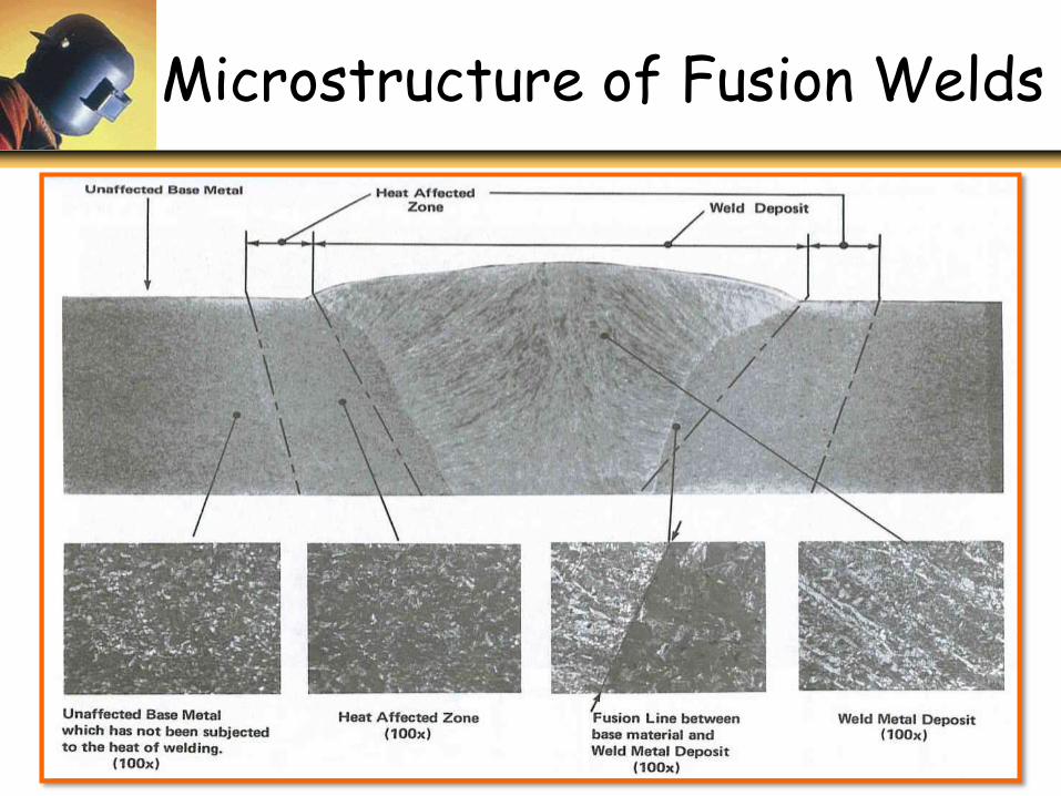
Microstructure of Fusion Welds
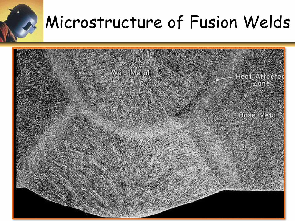
Microstructure of Fusion Welds
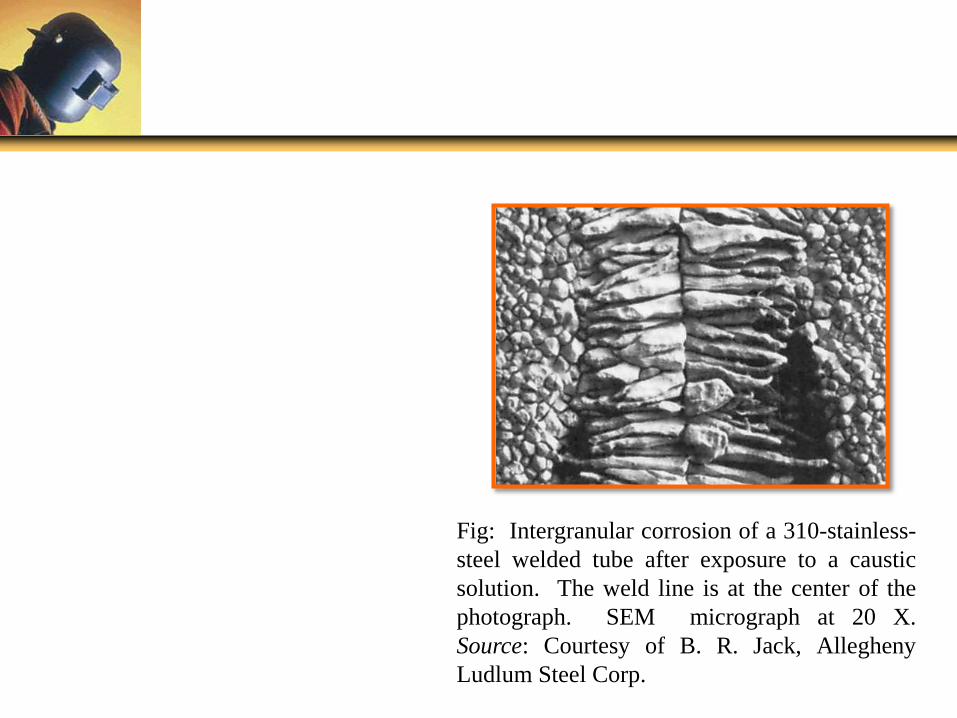
Fig: Intergranular corrosion of a 310-stainless-
steel welded tube after exposure to a caustic
solution. The weld line is at the center of the
photograph. SEM micrograph at 20 X.
Source: Courtesy of B. R. Jack, Allegheny
Ludlum Steel Corp.
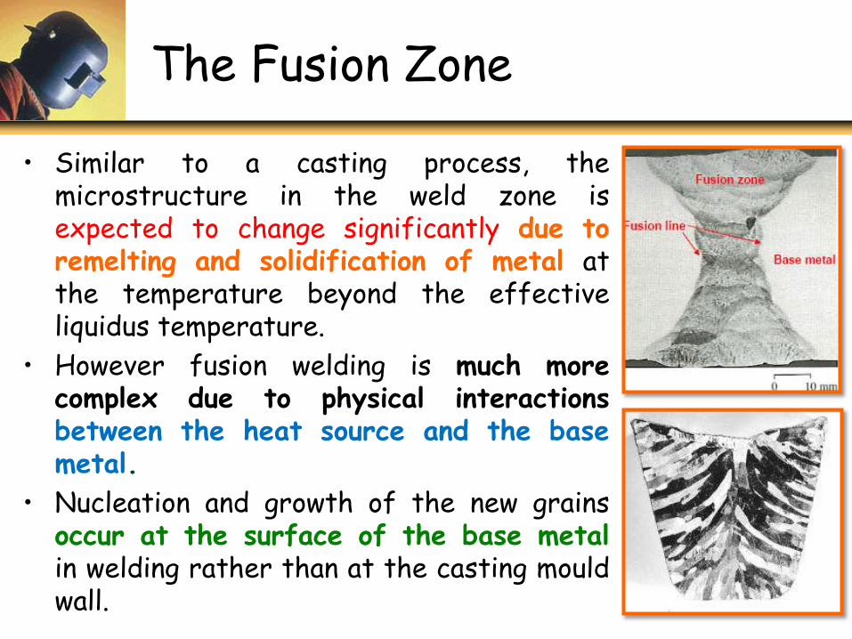
The Fusion Zone
• Similar to a casting process, themicrostructure in the weld zone isexpected to change significantly due toremelting and solidification of metal atthe temperature beyond the effectiveliquidus temperature.
• However fusion welding is much morecomplex due to physical interactionsbetween the heat source and the basemetal.
• Nucleation and growth of the new grainsoccur at the surface of the base metalin welding rather than at the casting mouldwall.
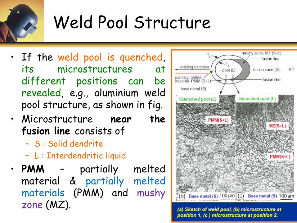
Weld Pool Structure
• If the weld pool is quenched,its microstructures atdifferent positions can berevealed, e.g., aluminium weldpool structure, as shown in fig.
• Microstructure near thefusion line consists of– S : Solid dendrite
– L : Interdendritic liquid
• PMM – partially meltedmaterial & partially meltedmaterials (PMM) and mushyzone (MZ).
1 - 16
Weld Pool Structure continued…
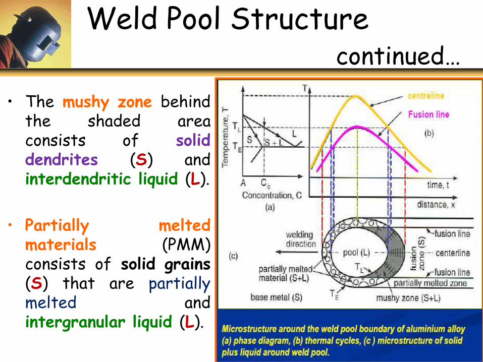
• The mushy zone behindthe shaded areaconsists of soliddendrites (S) andinterdendritic liquid (L).
• Partially meltedmaterials (PMM)consists of solid grains(S) that are partiallymelted andintergranular liquid (L).
1 - 17
Weld Pool Shape and Grain Structure
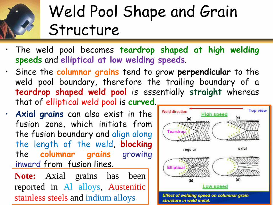
• The weld pool becomes teardrop shaped at high weldingspeeds and elliptical at low welding speeds.
• Since the columnar grains tend to grow perpendicular to theweld pool boundary, therefore the trailing boundary of ateardrop shaped weld pool is essentially straight whereasthat of elliptical weld pool is curved.
1 - 18
• Axial grains can also exist in thefusion zone, which initiate fromthe fusion boundary and align alongthe length of the weld, blockingthe columnar grains growinginward from fusion lines.
Note: Axial grains has been
reported in Al alloys, Austenitic
stainless steels and indium alloys
Effect of Welding Parameters on Weld Pool Shape
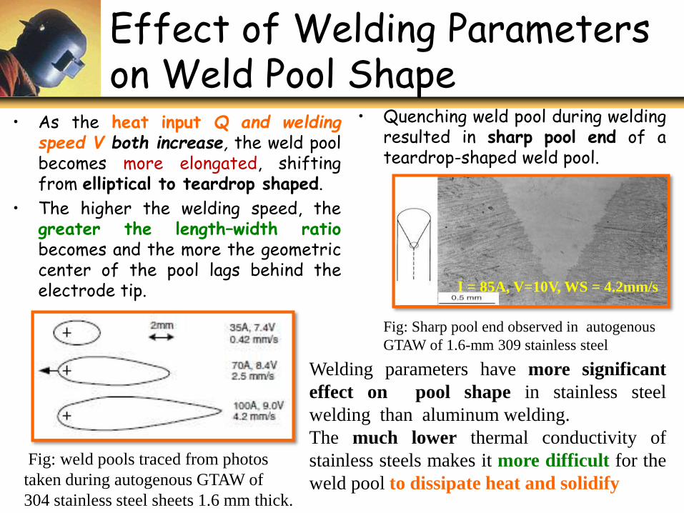
• As the heat input Q and weldingspeed V both increase, the weld poolbecomes more elongated, shiftingfrom elliptical to teardrop shaped.
• The higher the welding speed, thegreater the length–width ratiobecomes and the more the geometriccenter of the pool lags behind theelectrode tip.
• Quenching weld pool during weldingresulted in sharp pool end of ateardrop-shaped weld pool.
Fig: weld pools traced from photos
taken during autogenous GTAW of
304 stainless steel sheets 1.6 mm thick.
Welding parameters have more significant
effect on pool shape in stainless steel
welding than aluminum welding.
The much lower thermal conductivity of
stainless steels makes it more difficult for the
weld pool to dissipate heat and solidify
Fig: Sharp pool end observed in autogenous
GTAW of 1.6-mm 309 stainless steel
I = 85A, V=10V, WS = 4.2mm/s
Effect of Welding Speed on Weld Structure
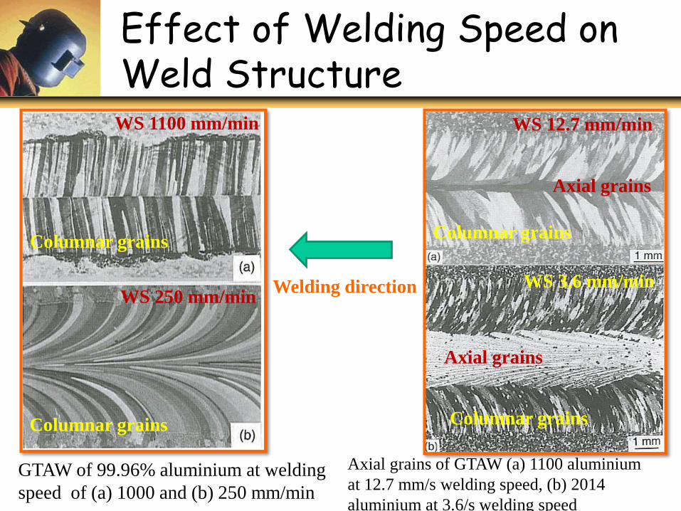
GTAW of 99.96% aluminium at welding
speed of (a) 1000 and (b) 250 mm/min
Axial grains of GTAW (a) 1100 aluminium
at 12.7 mm/s welding speed, (b) 2014
aluminium at 3.6/s welding speed
WS 1100 mm/min
WS 250 mm/min
Columnar grains
Columnar grains
WS 12.7 mm/min
WS 3.6 mm/min
Columnar grains
Columnar grains
Axial grains
Welding direction
Axial grains
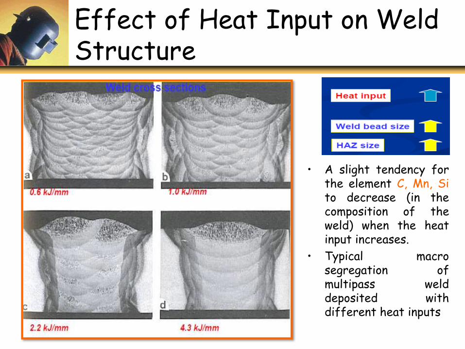
Effect of Heat Input on Weld Structure
• A slight tendency forthe element C, Mn, Sito decrease (in thecomposition of theweld) when the heatinput increases.
• Typical macrosegregation ofmultipass welddeposited withdifferent heat inputs
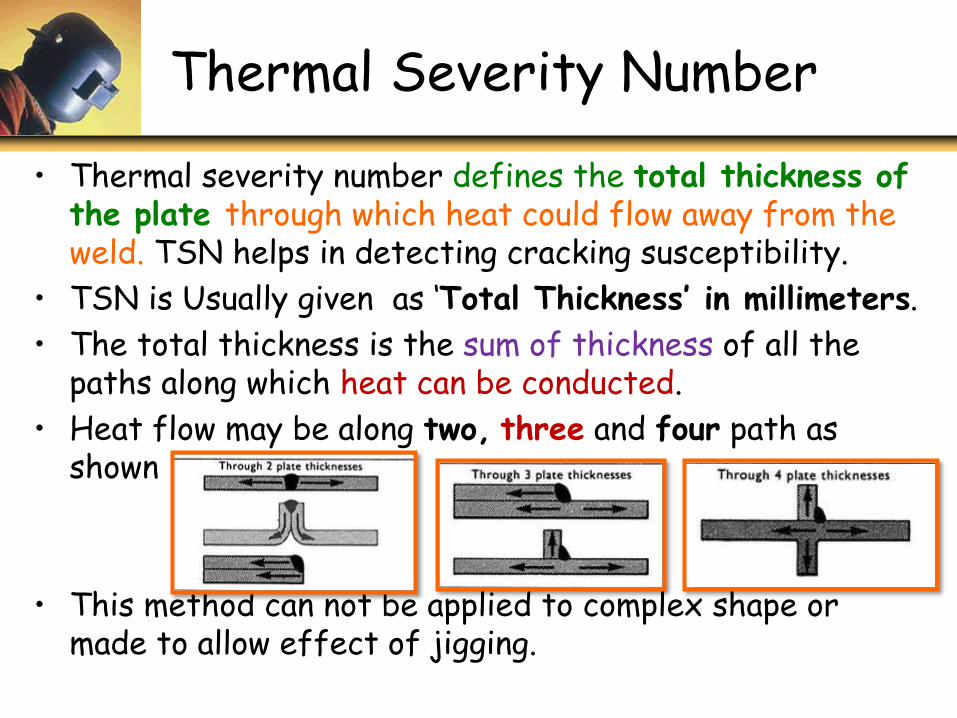
Thermal Severity Number
• Thermal severity number defines the total thickness of the plate through which heat could flow away from the weld. TSN helps in detecting cracking susceptibility.
• TSN is Usually given as ‘Total Thickness’ in millimeters.
• The total thickness is the sum of thickness of all the paths along which heat can be conducted.
• Heat flow may be along two, three and four path as shown
• This method can not be applied to complex shape or made to allow effect of jigging.
• TSN can be calculated
– For bithermal welds TSN = 4 (t + b)
– For Trithermal welds, TSN = 4 (t + 2b)
where: t and b are thickness of the top and bottom plate
• A series of plate thickness which provided varying cooling rates aretested. The crack susceptibility of the base metal – filler materialcombination is determined by the minimum TSN that produces cracking.
• Controlled thermal severity testing is used to measure the cold cracksensitivity of steels under cooling rates controlled by thickness of theplates.
• CTST specimen consists of a square plate bolted and anchor welded to alarger rectangular plate. After the anchor welds have cooled to roomtemperature, two test welds are made on the specimen. Fillet weldalong the plate edges is controlled by the thickness of the plates and thedifferences in cooling rates between bithermal and trithermal welds. Thistest is primarily used to evaluate the crack sensitivity of hardenablesteels
Thermal Severity Number continued…
1 - 24

![Models@run.timefor Self-adaptive Reactive Systemssma-site/workshopNii/workshopN... · c2 u4 u3 c4 u3 c1 u1 u2 u4 c3 c2 u3 c4 [] p1 p2 control monitor Motivation. Environment](https://img.dokumen.tips/doc/110x75/5ed6891eff0e593c0b640710/modelsruntimefor-self-adaptive-reactive-systems-sma-siteworkshopniiworkshopn.jpg)


![Ouray 400 Sistema [U4] Selux · U4-#2. U4-#3. U4-#4 U4-Fixture # Series Optics. Mounting Light. Options. Engine. Rivnut. Pairs RN Fixture # CCT Finish. Voltage *Refer to chart on](https://img.dokumen.tips/doc/110x75/5f94b53bcc58146dfa1c1ffc/ouray-400-sistema-u4-selux-u4-2-u4-3-u4-4-u4-fixture-series-optics-mounting.jpg)