Embed Size (px)
Citation preview
1
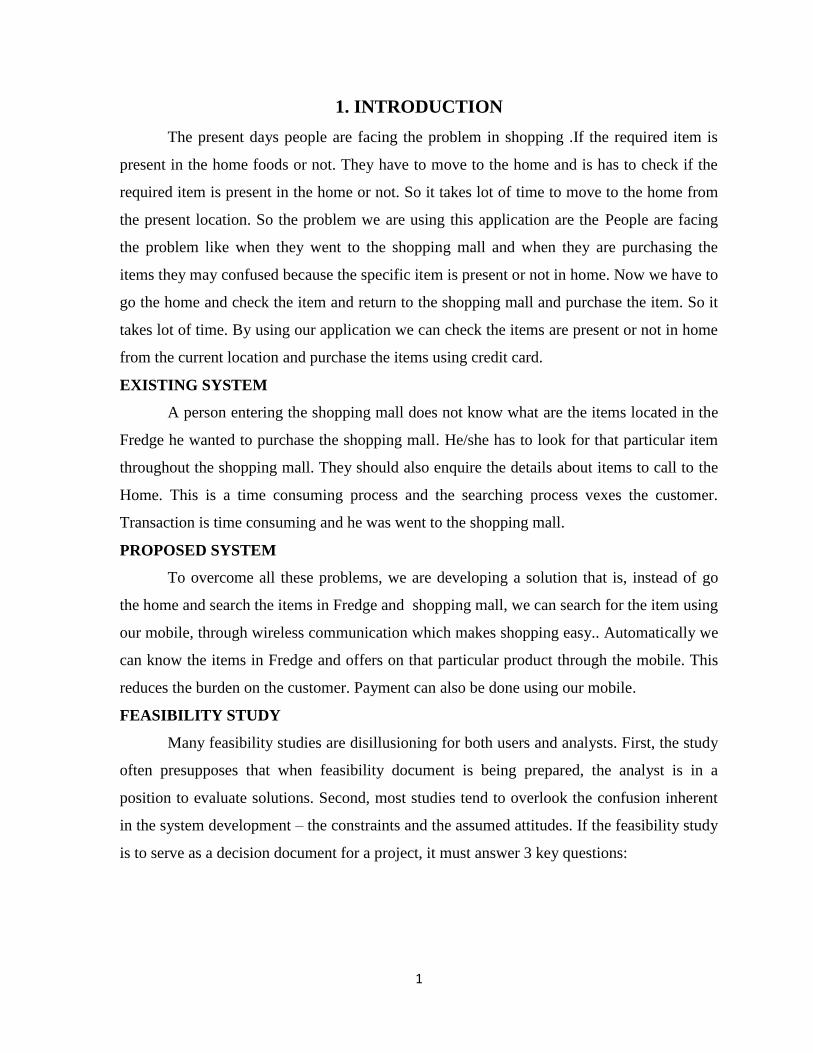
1. INTRODUCTION
The present days people are facing the problem in shopping .If the required item is
present in the home foods or not. They have to move to the home and is has to check if the
required item is present in the home or not. So it takes lot of time to move to the home from
the present location. So the problem we are using this application are the People are facing
the problem like when they went to the shopping mall and when they are purchasing the
items they may confused because the specific item is present or not in home. Now we have to
go the home and check the item and return to the shopping mall and purchase the item. So it
takes lot of time. By using our application we can check the items are present or not in home
from the current location and purchase the items using credit card.
EXISTING SYSTEM
A person entering the shopping mall does not know what are the items located in the
Fredge he wanted to purchase the shopping mall. He/she has to look for that particular item
throughout the shopping mall. They should also enquire the details about items to call to the
Home. This is a time consuming process and the searching process vexes the customer.
Transaction is time consuming and he was went to the shopping mall.
PROPOSED SYSTEM
To overcome all these problems, we are developing a solution that is, instead of go
the home and search the items in Fredge and shopping mall, we can search for the item using
our mobile, through wireless communication which makes shopping easy.. Automatically we
can know the items in Fredge and offers on that particular product through the mobile. This
reduces the burden on the customer. Payment can also be done using our mobile.
FEASIBILITY STUDY
Many feasibility studies are disillusioning for both users and analysts. First, the study
often presupposes that when feasibility document is being prepared, the analyst is in a
position to evaluate solutions. Second, most studies tend to overlook the confusion inherent
in the system development – the constraints and the assumed attitudes. If the feasibility study
is to serve as a decision document for a project, it must answer 3 key questions:

2
Three key considerations involved in the feasibility analysis:
Economical
Technical
Behavioral
Economic Feasibility
This application on the client side has been developed using J2ME Wireless Toolkit
2.2, which is open source software. The hardware required is access point, which is not
expensive. Hence the application is economically feasible.
Technical Feasibility
As the application has been developed using J2ME Wireless Toolkit 2.2 and the
back end as Oracle, which utilizes minimum resources of the Personal computer, this project
is technically feasible.
Operational Feasibility
This project has been implemented by J2ME WIRELESS TOOLKIT and it
satisfies all the conditions and norms of the users.
MODULES:
They are four modules in our project.
1. Registration of Items:
Registration enables items to get into our service.
2. Smart Fredge: The RFID reader reads the items in the smart Fredge and stores in
the database and give response to the user.
3. Search items in the mobile:
The user can access the information about the items through Mobile with the server.
4. Purchase the Required Items
The user can easily purchase the required items through a credit card.
3
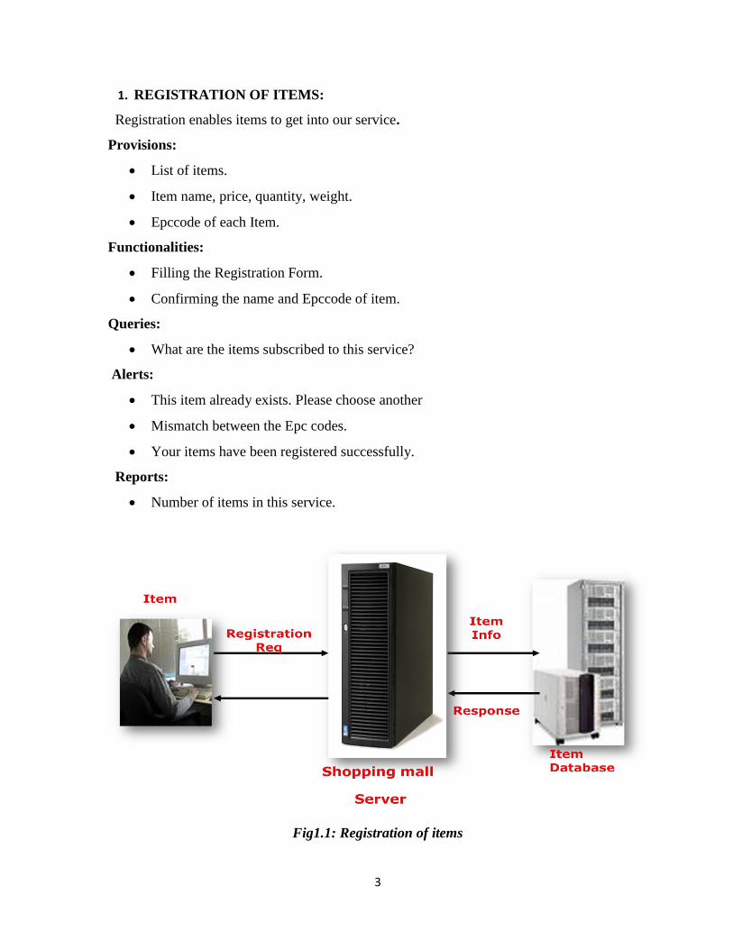
1. REGISTRATION OF ITEMS:
Registration enables items to get into our service.
Provisions:
List of items.
Item name, price, quantity, weight.
Epccode of each Item.
Functionalities:
Filling the Registration Form.
Confirming the name and Epccode of item.
Queries:
What are the items subscribed to this service?
Alerts:
This item already exists. Please choose another
Mismatch between the Epc codes.
Your items have been registered successfully.
Reports:
Number of items in this service.
Fig1.1: Registration of items
4
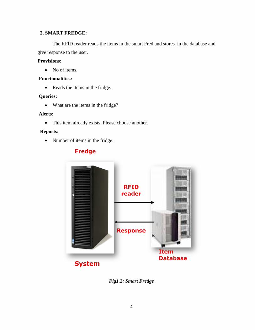
2. SMART FREDGE:
The RFID reader reads the items in the smart Fred and stores in the database and
give response to the user.
Provisions:
No of items.
Functionalities:
Reads the items in the fridge.
Queries:
What are the items in the fridge?
Alerts:
This item already exists. Please choose another.
Reports:
Number of items in the fridge.
Fig1.2: Smart Fredge

5
3. SEARCH ITEMS IN THE MOBILE:
The user can access the information about the items through Mobile with the server.
Provisions:
Item Name, Price, Quantity.
Functionalities:
Displays the items in the fridge.
Queries:
Select the item name?
Alerts:
This item not exists. Please choose another.
Reports:
Display of items in the fridge.
Fig1.3: Search Items in the Mobile

6
4. PURCHASE THE REQURIED ITEMS:
The user can easily purchase the required items through a credit card.
Provisions:
Item Name, Price, Quantity.
Functionalities:
Displays the items in the fridge.
Queries:
Select the item name?
Select the Quantity?
Alerts:
This item not Added Cart. Please choose Items.
Reports:
Display the Balance of the Amount in card.

7
2. PROBLEM DEFINATION AND SCOPE OF THE PROJECT
2.1PURPOSE:
The main purpose of the project is to manage the shopping efficiently for supermarket
. Supermarkets are getting crowded these days at the billing area and lot of time is being
consumed for billing the products. Also at the counter the person responsible must go
through the whole items which have been taken by the customers, it would be a time
consuming process. Presently we are using barcodes in supermarkets. Regarding the
barcodes, generally, a barcode is made up of a series of black and white lines. The cash
register uses the data from the code to identify the item and look up its latest price and print
the information on the customer’s receipt. Bar codes are commonly used to store data such as
prices and stock codes relating to products in shops and supermarkets. The items purchasing
after we would place in a fredge.we can place RFID reader to the Fredge.
Here we have some RFID tags to all the products present in the Fredge. The items are
read and stored into the server and we connect to server with a mobile view the items in
Fredge and With the help of these tags we can view for a particular product in the Fredge
through a mobile. Due to this we can read the items and select the required item to perform
automatic purchasing through a mobile, identify the items and also we can easily identify the
no stock goods in the Fredge.
2.2Scope
This application allows the users to search for the desired product in the Fredge so
that it saves the time of the user instead of checking the Fredge. User can check all the
information's like product cost, floor number, rack number and any concession on the
products and many more details through their mobiles. And they can pay the bill through
their mobile itself by using the credit cards and debit cards. It minimizes the risk taken by the
people to pay the bill.
2.3 Goals
By using this application we can check the items present or not from the current
location and purchase the items using credit card. so we can reduce the time for shopping.

8
2.4 Technologies
2.4.1 ORACLE 10G
Oracle Database 10g is the first database designed for grid computing, the most
flexible and cost-effective way to manage enterprise information. It cuts costs of
management while providing the highest possible quality of service.
In addition to providing numerous quality and performance enhancements, Oracle
Database 10g significantly reduces the costs of managing the IT environment, with a
simplified install, greatly reduced configuration and management requirements, and
automatic performance diagnosis and SQL tuning.
These and other automated management capabilities help improve DBA and
developer productivity and efficiency.10g is Oracle’s grid computing product group
including a database management system (DBMS) and an application server. In addition to
supporting grid computing features such as resource sharing and automatic load balancing,
10g products automate many database management tasks. The Real Application Cluster
(RAC) component makes it possible to install a database over multiple servers JDBC.
2.4.2 JDBC (JAVA DATABASE CONNECTIVITY)
JDBC technology is an API(included in both J2SE and J2EE releases) that provides
cross DBMS connectivity to a wide range of SQL database and access to other tabular data
sources, such as spreadsheets or flat files. With a JDBC technology-enabled driver, you can
connect all corporate data even in a heterogeneous environment.
The JDBC API makes it possible to do three things:
Establish a connection with a database or access any tabular data source
Send SQL statements
Process the results
TYPES OF JDBC TECHNOLOGY DRIVES
JDBC technology drivers fit into one of four categories:
A JDBC-ODBC bridge provides JDBC API access via one or more ODBC drivers.
A native-API partly Java technology-enabled driver converts JDBC calls into calls on
the client API for Oracle, Sybase, Informix, DB2, or other DBMS.

9
A net-protocol fully Java technology-enabled driver translates JDBC API calls into a
DBMS-independent net protocol which is then translated to a DBMS protocol by a
server.
A native-protocol fully Java technology-enabled driver converts JDBC technology
calls into the network protocol used by DBMSs directly.
JDBC ARCHITECTURE
The JDBC Architecture consists of two layers:
The JDBC API, which provides the application-to-JDBC Manager connection.
The JDBC Driver API, which supports the JDBC Manager-to-Driver Connection.
The JDBC API uses a driver manager and database-specific drivers to provide
transparent connectivity to heterogeneous databases. The JDBC driver manager ensures that
the correct driver is used to access each data source.
The location of the driver manager with respect to the JDBC drivers and the Java
application is shown in the figure below:
Java ApplicationApplication
JDBC API
JDBC Driver Manager
JDBC DriverJDBC DriverJDBC Driver
OracleSQL
Server
ODBCData
Source
Fig 2.4.2: JDBC Architecture
10
2.4.3 RFID TECHNOLOGY
The system aims to trace the position of workers, vehicle and machineries with the
help of RFID Technology. With the help of Tomcat Server, the administrator maintains all
the details of the workers, vehicle and machineries.
Radio-frequency identification (RFID) is the use of an object (typically referred to as
an RFID tag) applied to or incorporated into a product, animal, or person for the purpose of
identification and tracking using radio waves. Some tags can be read from several meters
away and beyond the line of sight of the reader.
Radio-frequency identification comprises readers and tags. The chip can store as
much as 2 kilobytes of data. To retrieve the data stored on an RFID tag, you need a reader. A
typical reader is a device that has one or more antennas that emit radio waves and receive
signals back from the tag. The reader then passes the information in digital form to a
computer system.
Most RFID tags contain at least two parts. One is an integrated circuit for storing and
processing information, modulating and demodulating a radio-frequency (RF) signal, and
other specialized functions.
The second is an antenna for receiving and transmitting the signal. There are
generally three types of RFID tags: active RFID tags, which contain a battery and can
transmit signals autonomously, passive RFID tags, which have no battery and require an
external source to provoke signal transmission, and battery assisted passive (BAP) RFID
tags, which require an external source to wake up but have significant higher forward link
capability providing great read range.
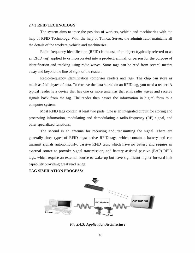
TAG SIMULATION PROCESS:
Fig 2.4.3: Application Architecture

11
Host Manages Reader(s) and Issues Commands.
Reader and tag communicate via RF signal.
Carrier signal generated by the reader (upon request from the host application)
Carrier signal sent out through the antennas.
Carrier signal hits tag(s).
Tag receives the carrier signal, modifies it and sends back the modulated signal.
Reader decodes the data and sends the results to the host application.
2.4.4 NETBEANS
Net Beans is first and foremost a well-crafted open source programmer's integrated
development environment (IDE). It's powerful, it's useful, it's extensible, it's open and it's
free. The practices which Net Beans imposes are fully as intricate as your current
development practices. More intricate, perhaps, because if you are a real programmer, you
will wish to supplement your work style with Net Beans rather than attempting to use Net
Beans to completely replace your current work style. The practice of Net Beans development
is not easier. It's just more effective than what you were doing before Net Beans.
It provides the services common to creating desktop applications such as window and
menu management, settings storage and is also the first IDE to fully support JDK 5.0
features.
FEATURES
Net Beans offers all the usual and expected features of an IDE:
A syntax-coloring editor aware not only of the Java language, but also XML, HTML
and many other languages
Component inspector
Object browser
Debugger
Integrated source control support for
External CVS
Built-in CVS
Most external source control systems of your choice
12
In addition to its own internal build system and compiler, Net Beans offers integration
with external compilers and
A dominant build tool in the Java/XML world and beyond
"Wizard" dialogs to assist the user at choice points.
APPLICATION
The Net Beans platform and IDE are free for commercial and non-commercial use,
and they are supported by Sun Microsystems. It can be downloaded from
http://www.netbeans.org/ to be able to successfully build programs it is recommended to
follow the intended procedure, described here. First it’s important to create a new project.
Various project types are available however in this case the intended type will be Java
Application.
It is recommended that you change the name of the project to something of this sort:
unit_1.Here the chosen location is: netbeans_home/workspace. To keep control over the way
that classes (e.g. the main launching class) are defined it is recommended to uncheck the two
check boxes. After Finish is clicked the new project structure will be in place, however we
now need to extend this by adding a new package. In this manner classes associated with the
same topics can be stored in one package. The end result will be multiple packages in one
project, each having a number of classes (programs). The process is simple, just right-click
on the Source Package label in Net Beans’ Projects tab and click New -> Java Package.
Here we will label the package as exercises. Clicking Finish will terminate this
process. Next we will create a simple class example and store it within our newly created
package. This process is very straight forward and involves a right-click on the appropriate
exercises package, after which we choose Java Class. Set the class name to Welcome. The
other details can be checked to verify that all is as intended. The new class structure will be
generated and at this point we need to edit the code and add the necessary lines. Note that the
first line of code is referring to the package name in which this class will be stored. The code
is missing a main method (since we un checked the check box previously, which we add.
Within this method we also need to add the line System.out.println (“Welcome to Java”);
Notice that while adding this line of code Net Beans’ editor will be suggesting stuff to
make our lives easier. The next step is to either save , compile and execute our program, or
else execute it directly (which will automatically save and compile). Any output from the
13
executed program will be displayed in the terminal window. In the above example the
program executed correctly and the intended message “Welcome to Java” displayed. If some
compile time and runtime errors were encountered, the appropriate exception message would
have also been displayed in this window.
2.4.5FRONT END PLATFORM – J2ME
To develop the user screens onto the mobiles we can use many software such as
MVNO, WINDOWS MOBILE, SYMBIAN, EMBEDDED VISUAL C++ AND .NET, J2ME
etc. Among all these available software we have chosen J2ME.
Client: J2ME
Client sends a request to the web server and the web server in turn sends the request
to the database to perform the request and the database sends the response to the web server
and the web server to the client.
About J2ME
Sun Microsystems defines J2ME as "a highly optimized Java run-time environment
targeting a wide range of consumer products, including pagers, cellular phones, screen-
phones, digital set-top boxes and car navigation systems."
Announced in June 1999 at the Java One Developer Conference, J2ME brings the
cross-platform functionality of the Java language to smaller devices, allowing mobile
wireless devices to share applications. With J2ME, Sun has adapted the Java platform for
consumer products that incorporate or are based on small computing devices.
Why J2ME?
J2ME is targeted to devices with limited horsepower and is supported by 90% of new
devices released to market. J2ME allows devices to browse, download and install Java
applications and content similar to browser applications. Since J2ME applications are
installed on the device, the applications can run without network coverage unlike browser
applications that always need a connection. J2ME offers a way to enter and persistently store
data on the device making applications faster and more user-friendly. J2ME has a
programming language that is easy to master, a runtime environment that provides a secure
and portable platform and a very large developer community. A java developer can quickly
master J2ME coding conventions from smart cards all the way to high powered devices like
high end PDA’s.
14
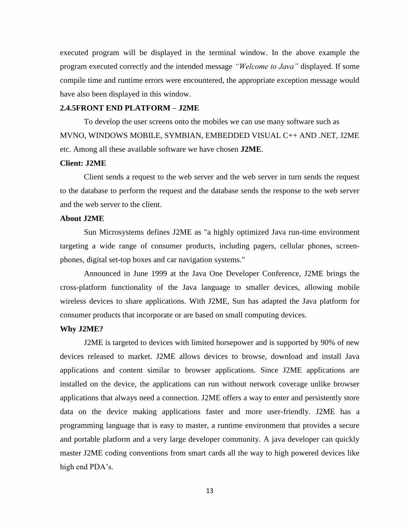
Fig 2.4.5.1:J2ME process
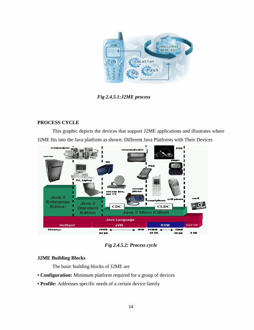
PROCESS CYCLE
This graphic depicts the devices that support J2ME applications and illustrates where
J2ME fits into the Java platform as shown: Different Java Platforms with Their Devices
Fig 2.4.5.2: Process cycle
J2ME Building Blocks
The basic building blocks of J2ME are
• Configuration: Minimum platform required for a group of devices
• Profile: Addresses specific needs of a certain device family

15
Fig 2.4.5.3: J2ME Building Blocks
Configurations
The J2ME platform covers a large range of different devices types. Devices like TV
set-top boxes, Internet TVs and high-end communicators have a large range of user interface
capabilities and memory budgets in range of 2 to 16 megabytes as well. On the other hand
devices like simple mobile phones, pagers and personal organizers have a very simple user
interface and low-level memory budget. Due to the large range of different type devices in
theJ2ME market place Sun has split the Java 2 Micro Edition in configurations.
Configurations define virtual machines features, Java language features and Java API
classes for each configuration environment. A J2ME configuration defines a minimum
platform for a “horizontal” class or family of devices, each with similar requirements on total
memory budget and processing power. A configuration defines the Java language and virtual
machine features and minimum libraries that a J2ME supported device manufacturer or a
content provider can expect to be available on all devices of the same class. To avoid
fragmentation that could lead to confusion, Sun has introduced until now only two
configurations, which are:

16
CLDC: Connected Limited Device Configuration
Very simple user interface (including no UI at all)
Low level memory budgets (160 KB to 512 KB)
16 or 32 bit processors
Wireless communication, possibly low bandwidth
Limited power, often battery operation.
Examples: Mobile phones, pagers and personal organizers.
CDC: Connected Device Configuration
Large range of user interface capabilities (down to and including no UI)
Memory budgets in range of 2 to 16 megabytes.
16 or 32 bit processors
Connectivity to some type of network
Examples: TV set-top boxes, Internet TVs and high-end communicators
CLDC versus CDC
The relationship between CDC, CLDC and Java 2 Standard Edition is illustrated in
figure. As shown there, the main functionality in CDC and CLDC is inherited from the J2SE.
All the classes which are inherited from the J2SE are precisely the same or a subsets of the
corresponding classes in the J2SE and the classes which are outside the J2SE environment
may not use the java.* class names. Thus, upward compatibility is achieved between the
different editions of Java 2 platforms. All features implemented in the CLDC are also
implemented in the CDC to achieve upward compatibility between J2ME configurations as
well. Thus, all applications implemented for the Connected Limited Device Configuration
platform can be run in the Connected Device Configuration platform as well.
Profiles:
Fig 2.4.5.4: profiles
17
The configurations help already a lot to distinguish different types of devices. But as
there so many types around they still have to be refined further because a configuration might
cover devices intended for totally different usage, like mobile phones and refrigerators, or
washing machines and set-top boxes. The mobile phone and e.g. a washing machine could
belong to the same configuration but it is obvious that a mobile phone application is not
expected to run on the washing machine or vice versa. Thus, the J2ME framework provides
the concept of a profile to achieve application environment portability. Profiles are
implemented on top of a configuration. Applications then are written for a specific profile, as
profiles are assembled for a specific configuration. Both profiles and configurations define a
set of Java API classes which can be used by the applications. A device that is designed to
support a profile or several profiles, agrees to implement all features and Java API classes
which are specified by the profile(s) and corresponding configuration. From an
implementation viewpoint, a profile is just a collection of Java APIs and class libraries
residing on top of a configuration and providing domain specific capabilities for devices in a
specific market segment.
MIDP: Mobile information device profile (on top of CLDC)
By building upon the CLDC, this profile will provide a standard platform for small,
resource-limited, wireless-connected mobile information devices like cellular phones and
two-way pagers. In addition to being wireless-connected, these devices have small
displays, limited input devices, limited local storage, battery life, and CPU power. Two types
of devices will be accommodated: mobile information appliances and voice communication
devices.
MIDlet Lifecycle
MIDlets move through a well-defines lifecycle consisting of five phases. It is the task
of the Application Management Software to move MIDlets through these phases:
Retrieval
The AMS retrieves the MIDlet from some source and reads the MIDlet into the
device’s memory. The medium through which the MIDlet is downloaded depends on the
device. It could be loaded through a serial cable, an IRDA port, or a wireless network.
18
Installation
Once the MIDlet is downloaded, the AMS installs the MIDlet on the device. During
the installation process, the MIDP implementation verifies that the MIDlet does not violate
the device’s security policies.
Launching
A MIDlet is launched when a user selects it using the interface provided in the device.
At this point, the MIDlet enters the KVM and the lifecycle methods of the MIDlet are
invoked.
Version Management
The AMS keeps track of all the MIDlets that are installed on the device including
their version numbers. This information is used to upgrade a MIDlet to its new version.
Removal
The AMS removes a MIDlet and cleans up the related resources from the memory.
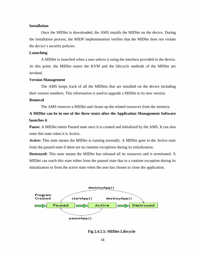
A MIDlet can be in one of the three states after the Application Management Software
launches it
Pause: A MIDlet enters Paused state once it is created and initialized by the AMS. It can also
enter this state when it is Active.
Active: This state means the MIDlet is running normally. A MIDlet goes to the Active state
from the paused state if there are no runtime exceptions during its initialization.
Destroyed: This state means the MIDlet has released all its resources and is terminated. A
MIDlet can reach this state either from the paused state due to a runtime exception during its
initialization or from the active state when the user has chosen to close the application.
Fig 2.4.5.5: MIDlet Lifecycle

19
3. SOFTWARE PROJECT MANAGEMENT PLAN (SPMP)
3.1 Development Methodologies-Process Model
When we defining and constructing credit card validation systems will uncover many
requirements that may be difficult at outset. Instead knowledge of the system and
requirements will grow as work progress the whole software engineering process is designed
to uncover details and incompatibilities in the requirements that may not be obvious to
customer and bankers at outset.
Several cases or increments of software development additional increases will be
build and delivered in successive increment system normally involves as are deliver
successive new versions, the development of first version from sketch called green field
development is special case of incremental development the development of first increment
is an important activity series we establish the architectural base that must last for the entire
system’s life time.
3.2 Project Development Life Cycle
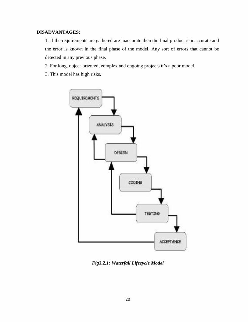
3.2.1 WATERFALL LIFECYCLE MODEL:
Waterfall model states that the phases (analysis, design, and coding, testing, support)
are systematized in a linear order and each phase should accomplished entirely earlier of the
next phase begins. In this way the step by step phase initially analyzing phase is completed
and that output takes place at the end of analyze phase after that output will be given as input
for the design phase, depending on the inputs it generates all design steps, like ways all
phases processed and produced all successful outputs, And will to find out whether the
project is pursuing on the exact path or not. If not the project may be discard or any other
action takes place to continue. The model is the most commonly used and also known as
linear sequential lifecycle model.
ADVANTAGES:
1. This model is very easy to use and implement.
2. Each phase is completed at a time and processed.
3. This model better works for smaller projects if only the requirements are well
understood.
4. In each phase have deliverables and that must be reviewed.
20
DISADVANTAGES:
1. If the requirements are gathered are inaccurate then the final product is inaccurate and
the error is known in the final phase of the model. Any sort of errors that cannot be
detected in any previous phase.
2. For long, object-oriented, complex and ongoing projects it’s a poor model.
3. This model has high risks.
Fig3.2.1: Waterfall Lifecycle Model

21
4. SYSTEM AND SOFTWARE REQUIREMENT SPECIFICATIONS
4.1FUNCTIONAL REQUIREMENTS
In mobile shopping application, the customers can view the details about the product
from the implementation of the product search module.
The new user can login into the system by registering into the Admin and the login
into the system.
The customer can view the information about the offers on the desired products from
the profile based ads module.
The user can pay the bill using credit card/debit card from the implementation of the
bill payment module.
4.2 NON FUNCTIONAL REQUIREMENTS
Requirement specification plays an important part in the analysis of a system. Only
when the requirement specifications are properly given, it is possible to design a system,
which will fit into required environment. It rests largely with the users of the existing system
to give the requirement specifications because they are the people who finally use the system.
This is because the requirements have to be known during the initial stages so that the system
can be designed according to those requirements. It is very difficult to change the system
once it has been designed and on the other hand designing a system, which does not cater to
the requirements of the user, is of no use.
The requirement specification for any system can be broadly stated as given below:
The system should be able to interface with the existing system
The system should be accurate
The system should be better than the existing system
The existing system is completely dependent on the user to perform all the duties.
4.3HARDWARE INTERFACE:
Client Side Mobile Phone which is Access the Internet and Application.
Server Side RAM : 256 MB or more
Hard disk : 40 GB hard disk recommended.
Tools : RFID Reader, RFID Tag.

22
4.4SOFTWARE INTERFACE:
Client Side
Programming language: java1.5 or jdk5,j2me
Tools : J2ME toolkit2.5.2.
Operating system : Windows XP or later
Technology : Java 2 Micro Edition (J2ME)
Server Side
Front End
Operating system : Windows XP or later
Technology : JDBC.
Tools : Net Beans IDE 6.9.1
Back End
Database : Oracle 10g
Server : Apache Tomcat 6.0
4.5 COMMUNICATION INTERFACE: GPRS, RFID Reader, RFID Tag.
23
5. SOFTWARE DESIGN DESCRIPTION
5.1 DESIGN
Design is the first step in the development phase for any engineering product or
system. It may be defined as a “the process of applying various techniques and principles for
the purpose of defining a device, a process, or a system insufficient detail to permit its
physical realization”.
Software design is an iterative process through which requirements are translated into
a “blue print” for the constructing software. The design is represented at high level of
abstraction, a level that can be directly translated to a specific data, functional behavior
requirements. Preliminary design is concerned the transformation of requirements into a data
and software architecture.
The design is solution, a “how to” approach to the creation of a new system. This is
composed of several steps. It provides the understanding and procedural details necessary for
implementing the system recommended.
The database design transforms the information domain model created during
analysis into the data structures that will be required to implemented software.
The architecture design describes how the software communicates within itself, to
systems that interoperate with it, and with humans who use it. An interface implements flow
of information.
The interface design describes how the software communicates within itself, to
systems that interoperate with it, and with humans who use it. An interface implements flow
of information.
5.1.1 INPUT DESIGN
Input design is the process of converting user-oriented input to a computer based
format. Input design is a part of overall system design, which requires very careful attention.
Often the collection of input data is the most expensive part of the system. The main
objectives of the input design are
Produce cost effective method of input
Achieve highest possible level of accuracy
Ensure that the input is acceptable to and understood by the staff.

24
5.1.1.1 INPUT DATA
The goal of designing input data is to make entry easy, logical and free from errors as
possible. The entering data entry operators need to know the allocated space for each field;
field sequence and which must match with that in the source document. The format in which
the data fields are entered should be given in the input form .Here data entry is online; it
makes use of processor that accepts commands and data from the operator through a key
board. The input required is analyzed by the processor. It is then accepted or rejected. Input
stages include the following processes:
Data Recording
Data Transcription
Data Conversion
Data Verification
Data Control
Data Transmission
Data Correction
One of the aims of the system analyst must be to select data capture method and
devices, which reduce the number of stages so as to reduce both the changes of errors and the
cost .Input types, can be characterized as:
External
Internal
Operational
Computerized
Interactive
Input files can exist in document form before being input to the computer. Input
design is rather complex since it involves procedures for capturing data as well as inputting it
to the computer.
5.1.2 OUTPUT DESIGN
Outputs from computer systems are required primarily to communicate the results of
processing to users. They are also used to provide a permanent copy of these result for latter
consultation .Computer output is the most important and direct source of information to the
users. Designing computer output should proceed in an organized well throughout the
25
manner. The right output must be available for the people who find the system easy o use.
The outputs have been defined during the logical design stage. If not, they should defined at
the beginning of the output designing terms of types of output connect, format, response etc,
Various types of outputs are
External outputs
Internal outputs
Operational outputs
Interactive outputs
Turn around outputs
All screens are informative and interactive in such a way that the user can fulfill his
requirements through asking queries.
5.2 UML Diagrams
INTRODUCTION:
Design is the place where quality is fostered in software development. Design is the
only way that we can accurately translate a user’s requirements into a finished software
product or system. Software design serves as the foundation for all software engineers and
software maintenance steps that follow. Without design we risk building an unstable design –
one that will fail when small changes are made, one that may be difficult to test, and one
whose quantity cannot be assessed until late in the software engineering process.
Taking software requirements specification document of analysis phase as input to the design
phase we have drawn Unified Modeling Language (UML) diagrams. UML depends on the
Visual modeling of the system. Visual modeling is the process of taking the information from
the model and displaying it graphically using some sort of standards set of graphical
elements.
UML Diagrams are drawn using the Visual Paradigm Software. We seem to be able
to understand complexity better when it is displayed to us visually as opposed to written
textually. By producing visual models of a system, we can show how system works on
several levels. We can model the interactions between the users and the system.
26
TYPES OF UML DIAGRAMS
Each UML diagram is designed to let developers and customers view a software
system from a different perspective and in varying degrees of abstraction. UML diagrams
commonly created in visual modeling tools include;
Use Case Diagram: Displays the relationship among actors and use cases.
Class Diagram: Models class structure and contents using design elements such as classes,
packages and objects. It also displays relationships such as containment, inheritance,
associations and others.
Interaction Diagrams:
Sequence Diagram: Displays the time sequence of the objects participating in the
interaction. This consists of the vertical dimension (time) and horizontal dimension
(different objects).
Collaboration Diagram: Displays an interaction organized around the objects and their
links to one another. Numbers are used to show the sequence of messages.
State Diagram: Displays the sequences of states that an object of an interaction goes through
during its life in response to received stimuli, together with its responses and actions.
Activity Diagram: Displays a special state diagram where most of the states are action states
and most of the transitions are triggered by completion of the actions in the source states.
This diagram focuses on flows driven by internal processing.
Physical Diagrams:
Component Diagram: Displays the high level packaged structure of the code itself.
Dependencies among components are shown, including source code components, binary
code components, and executable components. Some components exist at compile time, at
link time, at run times well as at more than one time.
Deployment Diagram: Displays the configuration of run-time processing elements and the
software components, processes, and objects that live on them. Software component
instances represent run-time manifestations of code units.
Views of UML Diagrams
Considering that the UML diagrams can be used in different stages in the life cycle of
a system, let us take a look at the "4+1 view" of UML diagrams. The 4+1 view offers a
different perspective to classify and apply UML diagrams. The 4+1 view is essentially how a
27
system can be Each of these views represents how a system can be modeled. This will enable
us to understand where exactly the UML diagrams fit in and their applicability. viewed from
a software life cycle perspective. Each of these views represents how a system can be
modeled. This will enable us to understand where exactly the UML diagrams fit in and their
applicability.
The different views are:
Design View:
The design view of a system is the structural view of the system. This gives an idea of
what a given system is made up of. Class diagrams and object diagrams form the design view
of the system.
Process View:
The dynamic behavior of a system can be seen using the process view. The different
diagrams such as the state diagram, activity diagram, sequence diagram, and collaboration
diagram are used in this view.
Component View:
Component view shows the grouped modules of a given system modeled using the
component diagram.
Deployment View:
The deployment diagram of UML is used to identify the deployment modules for a
given system.
Use case View:
Finally, we have the use case view. Use case diagrams of UML are used to view a
system from this perspective as a set of discrete activities or transactions.
28
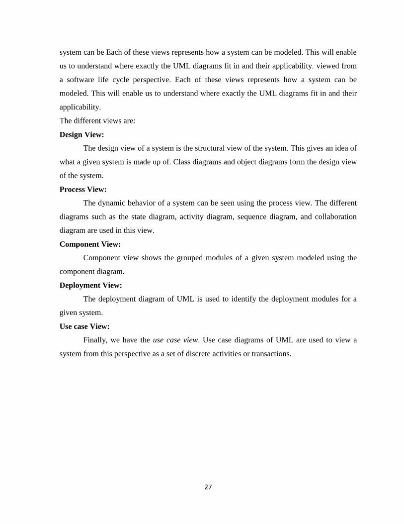
5.2.1 Use case diagram for customer
Fig5.2.1: Use case diagram for customer
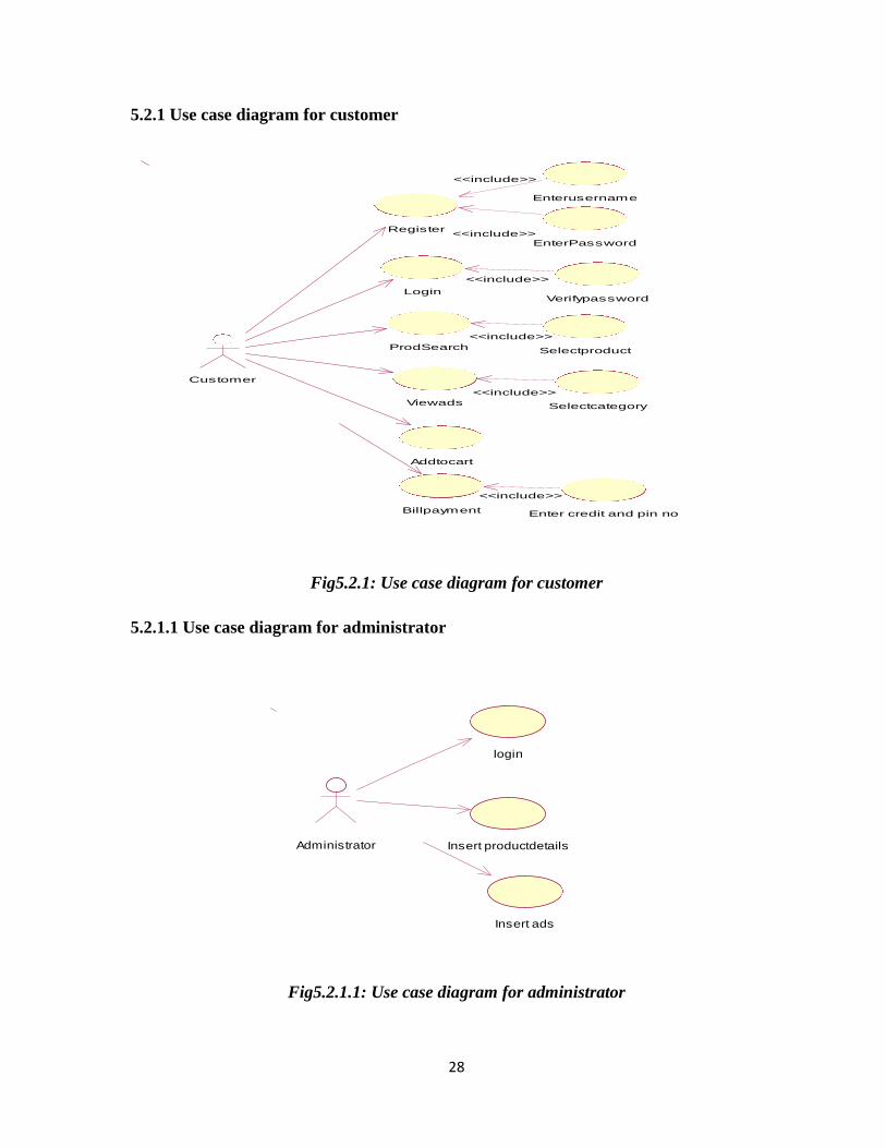
5.2.1.1 Use case diagram for administrator
Fig5.2.1.1: Use case diagram for administrator
Enterusername
EnterPassword
Verifypassword
Selectproduct
Selectcategory
Enter credit and pin no
Register
<<include>>
<<include>>
Login
<<include>>
ProdSearch
<<include>>
Viewads
<<include>>
Addtocart
Customer
Billpayment
<<include>>
login
Insert productdetailsAdministrator
Insert ads

29
5.2.2 Class Diagram
Fig5.2.2: Class diagram
30
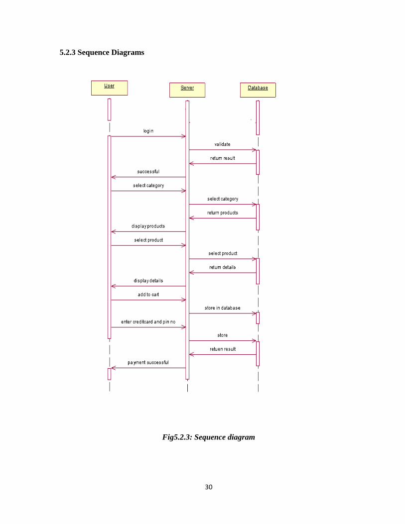
5.2.3 Sequence Diagrams
Fig5.2.3: Sequence diagram

31
5.2.4 Activity Diagram
Fig5.2.4: Activity diagram

32
5.2.5Entity Relationship Diagram
(1,*) (1,*) (1,*)
(1,1)
(0,*)
(1,1)
(1,*)
(1,1)
Fig 5.2.5: ER diagram
has
PRODUCT
ADS VIEWS
CUSTOMER
PURCH
ASES
BILL
pays Has

33
5.2.6 DATA FLOW DIAGRAMS
USER REGISTRATION
Fig5.2.6: Data Flow Diagrams User
PRODUCT SEARCH
Fig5.2.6: Data Flow Diagrams Product Search
BILL PAYMENT
Fig5.2.6: Data Flow Diagrams Bill Payment
34
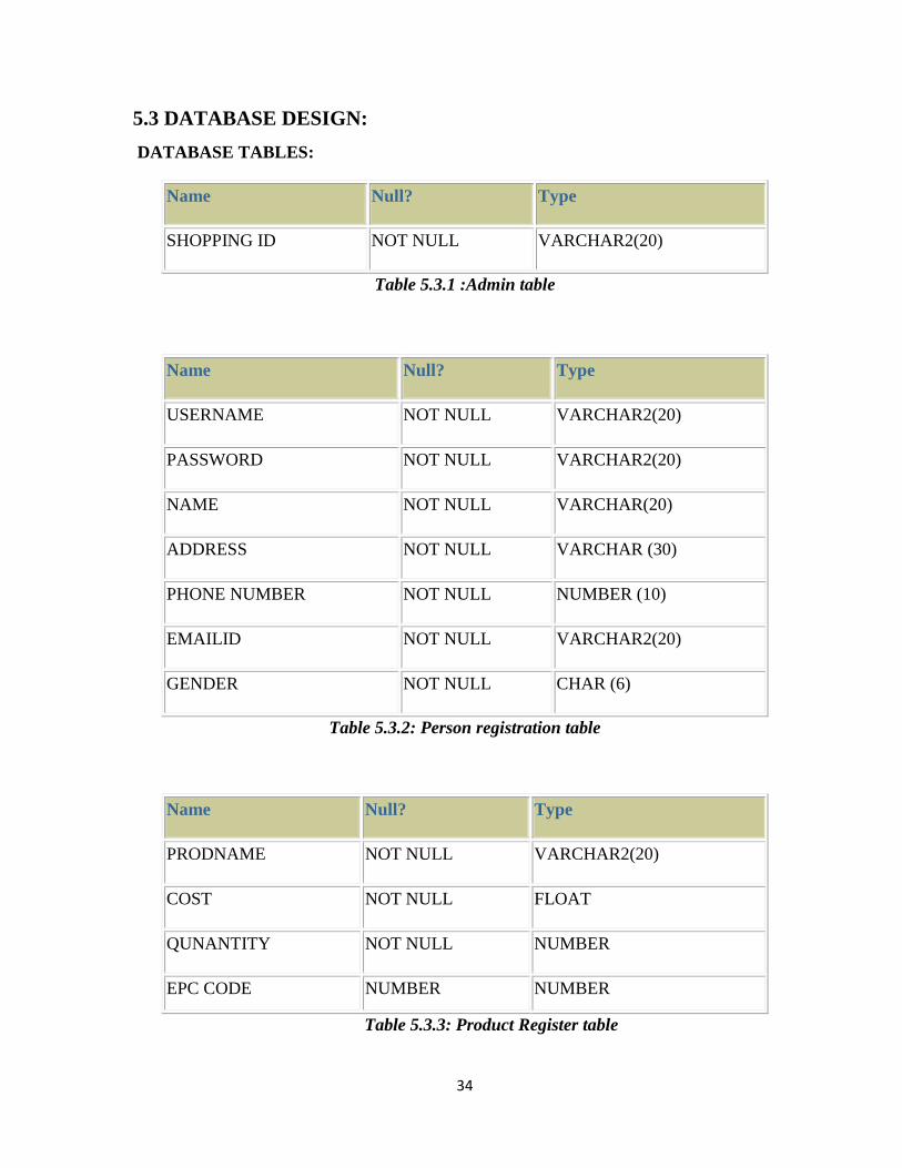
5.3 DATABASE DESIGN:
DATABASE TABLES:
Name Null? Type
SHOPPING ID NOT NULL VARCHAR2(20)
Table 5.3.1 :Admin table
Name Null? Type
USERNAME NOT NULL VARCHAR2(20)
PASSWORD NOT NULL VARCHAR2(20)
NAME NOT NULL VARCHAR(20)
ADDRESS NOT NULL VARCHAR (30)
PHONE NUMBER NOT NULL NUMBER (10)
EMAILID NOT NULL VARCHAR2(20)
GENDER NOT NULL CHAR (6)
Table 5.3.2: Person registration table
Name Null? Type
PRODNAME NOT NULL VARCHAR2(20)
COST NOT NULL FLOAT
QUNANTITY NOT NULL NUMBER
EPC CODE NUMBER NUMBER
Table 5.3.3: Product Register table

35
Name Null? Type
PRODNAME NOT NULL VARCHAR2(20)
COST NOT NULL FLOAT
QUANTITY NUMBER
Table 5.3.4 :Cart table
Name Null? Type
CARDNO NOT NULL NUMBER(16)
PIN NOT NULL NUMBER(4)
BALANCE NOT NULL NUMBER(20)
Table 5.3.5: Credit card table

36
6. SAMPLE CODE AND SCREEN SHOTS
6.1Sample Code:
Login page:
import javax.microedition.lcdui.*;
import javax.microedition.midlet.*;
public class LoginForm implements CommandListener,ItemCommandListener,Runnable{
Form f;
TextField tf1,tf2;
ImageItem it;
Command c1,c2;
static String s1;
StringItem si;
Ticker t;
Image img;
public LoginForm(){
f=new Form("Login Form");
t=new Ticker("Welcome to shopping");
tf1=new TextField("username:","",20,TextField.ANY);
tf2=new TextField("password:","",20,TextField.PASSWORD);
c1=new Command("login:",Command.OK,1);
c2=new Command("Cancel:",Command.OK,2);
si=new StringItem("","Login",Item.BUTTON);
si.setLayout(Item.LAYOUT_CENTER);
si.setDefaultCommand(c1);
si.setItemCommandListener(this);
try{
img=Image.createImage("/bean.PNG");
it=new ImageItem("Image:",img,Item.LAYOUT_CENTER,null,Item.BUTTON);
it.setDefaultCommand(c1);
it.setItemCommandListener(this);
}

37
catch(Exception e){
e.printStackTrace();
}
}
public void display(){
f.setTicker(t);
f.append(tf1);
f.append(tf2);
f.append(it);
f.append(si);
f.addCommand(c1);
f.addCommand(c2);
f.setCommandListener(this);
sample.dis.setCurrent(f);
}
public void commandAction(Command c,Displayable d){
if(c == c1){
}
if(c == c2){
}
}
public void commandAction(Command c,Item i){
if(i == si){
try{
Thread t=new Thread(this);
t.start();
}
catch (Exception e){
e.printStackTrace();
}
}
38
}
public void run(){
s1=tf1.getString();
String s2=tf2.getString();
String url="http://localhost:8888/mobileApp/login?username="+s1+"&password="+s2;
String res=ConnectionUtility.sendResponse(url);
res=res.trim();
System.out.println(res);
if(res.equals("valid user")){
Alert a=new Alert("Login Alert","valid user",null,AlertType.INFO);
a.setTimeout(Alert.FOREVER);
sample.dis.setCurrent(a);
try{
Thread.sleep(2000);
}
catch (Exception ex){
ex.printStackTrace();
}
HomeForm hf = new HomeForm();
hf.display();
}
else{
Alert a1=new Alert("Login Alert","Not valid user ",null,AlertType.INFO);
a1.setTimeout(Alert.FOREVER);
sample.dis.setCurrent(a1);
}
}
}
Details Form:
import javax.microedition.lcdui.*;
public class DetailsForm implements CommandListener,ItemCommandListener,Runnable{

39
Form f;
Command c1,c2;
Ticker t;
ChoiceGroup cg;
StringItem si,si1,si2,si3,si4;
static String s1,s2;
String temp;
int flag;
public DetailsForm(){
f=new Form("Items details");
t=new Ticker("welcome to my app....");
c1=new Command("",Command.OK,1);
si=new StringItem("","Add to Cart",Item.BUTTON);
si.setLayout(Item.LAYOUT_CENTER);
si.setDefaultCommand(c1);
si.setItemCommandListener(this);
si4=new StringItem("","View Cart",Item.BUTTON);
si4.setLayout(Item.LAYOUT_CENTER);
si4.setDefaultCommand(c1);
si4.setItemCommandListener(this);
si1 = new StringItem("Quantity:","");
si2 = new StringItem("Price:","");
si3 = new StringItem("EPC code:","");
}
public void display(String resp){
f.setTicker(t);
f.append(si1);
f.append(si2);
f.append(si3);
int i=0;
if((i=resp.indexOf('$'))!=-1){
40
temp=resp.substring(0,i);
temp=temp.trim();
si1.setText(temp);
resp=resp.substring(i+1);
}
if((i=resp.indexOf('$'))!=-1){
temp=resp.substring(0,i);
temp=temp.trim();
si2.setText(temp);
resp=resp.substring(i+1);
}
if((i=resp.indexOf('$'))!=-1){
temp=resp.substring(0,i);
temp=temp.trim();
si3.setText(temp);
resp=resp.substring(i+1);
}
f.append(si);
f.append(si4);
f.setCommandListener(this);
sample.dis.setCurrent(f);
}
public void commandAction(Command c,Displayable d){
if(c==c1){
}
}
public void commandAction(Command c,Item i){
if(i==si){
try{
flag=0;
Thread t=new Thread(this);
41
t.start();
}
catch (Exception e){
e.printStackTrace();
}
}
if(i==si4){
try{
flag=1;
Thread t1=new Thread(this);
t1.start();
}
catch (Exception e){
e.printStackTrace();
}
}
}
public void run(){
if(flag==0){
s1=si2.getText();
s2=LoginForm.s1;
String
url="http://localhost:8888/mobileApp/add?username="+s2+"&product="+Items.s2+"&price
="+s1;
String res=ConnectionUtility.sendResponse(url);
res=res.trim();
System.out.println(res);
if(res.equals("inserted")){
Alert a=new Alert("items Alert","Added to Cart",null,AlertType.INFO);
a.setTimeout(Alert.FOREVER);
sample.dis.setCurrent(a);

42
try{
Thread.sleep(2000);
}
catch (Exception ex){
ex.printStackTrace();
}
HomeForm hf = new HomeForm();
hf.display();
}
else{
Alert a1=new Alert("items Alert"," Not Added",null,AlertType.INFO);
a1.setTimeout(Alert.FOREVER);
sample.dis.setCurrent(a1);
}
}
if(flag==1){
s1=si4.getText();
s2=LoginForm.s1;
String url="http://localhost:8888/mobileApp/cartdetails?username="+s2+"";
String res=ConnectionUtility.sendResponse(url);
res=res.trim();
System.out.println(res);
if(res.equals("")){
Alert a1=new Alert("items Alert"," No items",null,AlertType.INFO);
a1.setTimeout(Alert.FOREVER);
sample.dis.setCurrent(a1);
}
else{
CartForm cf = new CartForm();
cf.display(res);
}
43
}
}
}
Login servlet:
import javax.servlet.*;
import javax.servlet. Http.*;
import java.io.*;
import java.sql.*;
public class LoginServlet extends HttpServlet{
static Connection con;
static PreparedStatement pst;
static ResultSet rs;
public void service(HttpServletRequest req,HttpServletResponse res)throws
IOException,ServletException{
res.setContentType("text/html");
PrintWriter out=res.getWriter();
String s1=req.getParameter("username");
String s2=req.getParameter("password");
try{
Class.forName("oracle.jdbc.driver.OracleDriver");
con=DriverManager.getConnection("jdbc:oracle:thin:@localhost:1521:xe","system","manag
er");
pst=con.prepareStatement("select * from register where username=? and password=?");
pst.setString(1,s1);
pst.setString(2,s2);
rs=pst.executeQuery();
if(rs.next()){
out.println("valid user");
System.out.println("valid user");
}
else{

44
out.println("Not valid user");
System.out.println("Not valid user");
}
}
catch (Exception e){
e.printStackTrace();
}
finally{
try{
pst.close();
con.close();
}
catch (Exception e){
e.printStackTrace();
}
}
}
}
Details servlet
import javax.servlet.*;
import javax.servlet.http.*;
import java.io.*;
import java.sql.*;
public class DetailsServlet extends HttpServlet{
static Connection con;
static PreparedStatement pst;
static ResultSet rs;
public void service(HttpServletRequest req,HttpServletResponse res)throws
IOException,ServletException{
res.setContentType("text/html");
PrintWriter out=res.getWriter();

45
String s1=req.getParameter("ItemName");
try{
Class.forName("oracle.jdbc.driver.OracleDriver");
con=DriverManager.getConnection("jdbc:oracle:thin:@localhost:1521:xe","system","manag
er");
pst=con.prepareStatement("select * from itemRegister where itemname=?");
pst.setString(1,s1);
rs=pst.executeQuery();
if(rs.next()){
String response = rs.getString(2)+"$"+rs.getString(3)+"$"+rs.getString(4)+"$";
out.println(response);
}
}
catch (Exception e){
e.printStackTrace();
}
finally{
try{
pst.close();
con.close();
}
catch (Exception e){
e.printStackTrace();
}
}
}
}
Pay servlet
public class PayServlet extends HttpServlet{
static Connection con; import javax.servlet.*;
import javax.servlet.http.*;

46
import java.io.*;
import java.sql.*;
static PreparedStatement pst;
static ResultSet rs;
public void service(HttpServletRequest req,HttpServletResponse res)throws
IOException,ServletException{
res.setContentType("text/html");
PrintWriter out=res.getWriter();
String s1=req.getParameter("Creditcardno");
String s2=req.getParameter("Pin");
String s3=req.getParameter("amt");
String s4=req.getParameter("username");
int amt = Integer.parseInt(s3);
try{
Class.forName("oracle.jdbc.driver.OracleDriver");
con=DriverManager.getConnection("jdbc:oracle:thin:@localhost:1521:xe","system","manag
er");
pst=con.prepareStatement("select * from card5 where cardnumber=? and cardcode=?");
pst.setString(1,s1);
pst.setString(2,s2);
rs=pst.executeQuery();
if(rs.next()){
String balance = rs.getString(3);
int bal = Integer.parseInt(balance);
bal = bal-amt;
String bb = Integer.toString(bal);
pst=con.prepareStatement("update card set balance=? where cardnumber=? and
cardcode=?");
pst.setString(1,bb);
pst.setString(2,s1);
pst.setString(3,s2);

47
int i = pst.executeUpdate();
if(i>0){
pst=con.prepareStatement("delete from item where username=?");
pst.setString(1,s4);
int j = pst.executeUpdate();
if(j>0){
out.println("paid");
}
}
}
else{
out.println("Not valid card");
System.out.println("Not valid card");
}
}
catch (Exception e){
e.printStackTrace();
}
finally{
try
{
pst.close();
con.close();
}
catch (Exception ex){
ex.printStackTrace();
}
}
}
}

48
SCREEN SHOTS:
6.2 login Form
Fig 6.2: Login Form
49
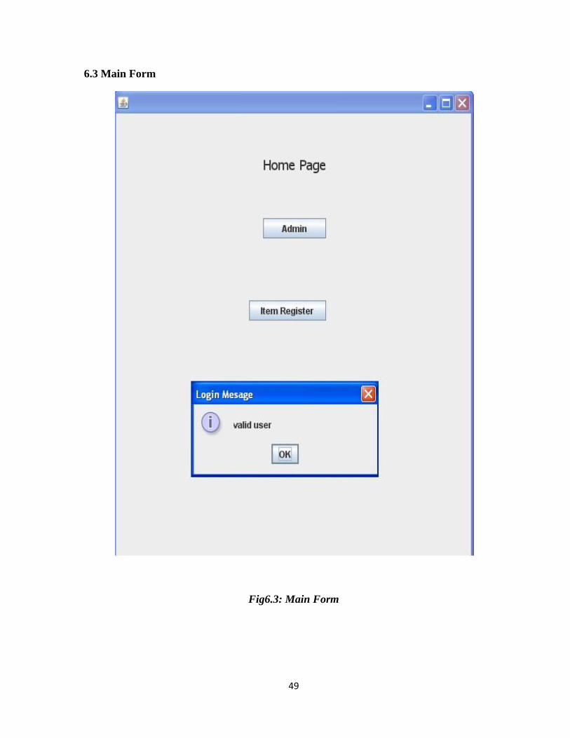
6.3 Main Form
Fig6.3: Main Form

50
6.4 Item Verify Form
Fig6.4: Item Verify Form

51
6.5 Item Modify Form
Fig6.5: Item Modify Form
52
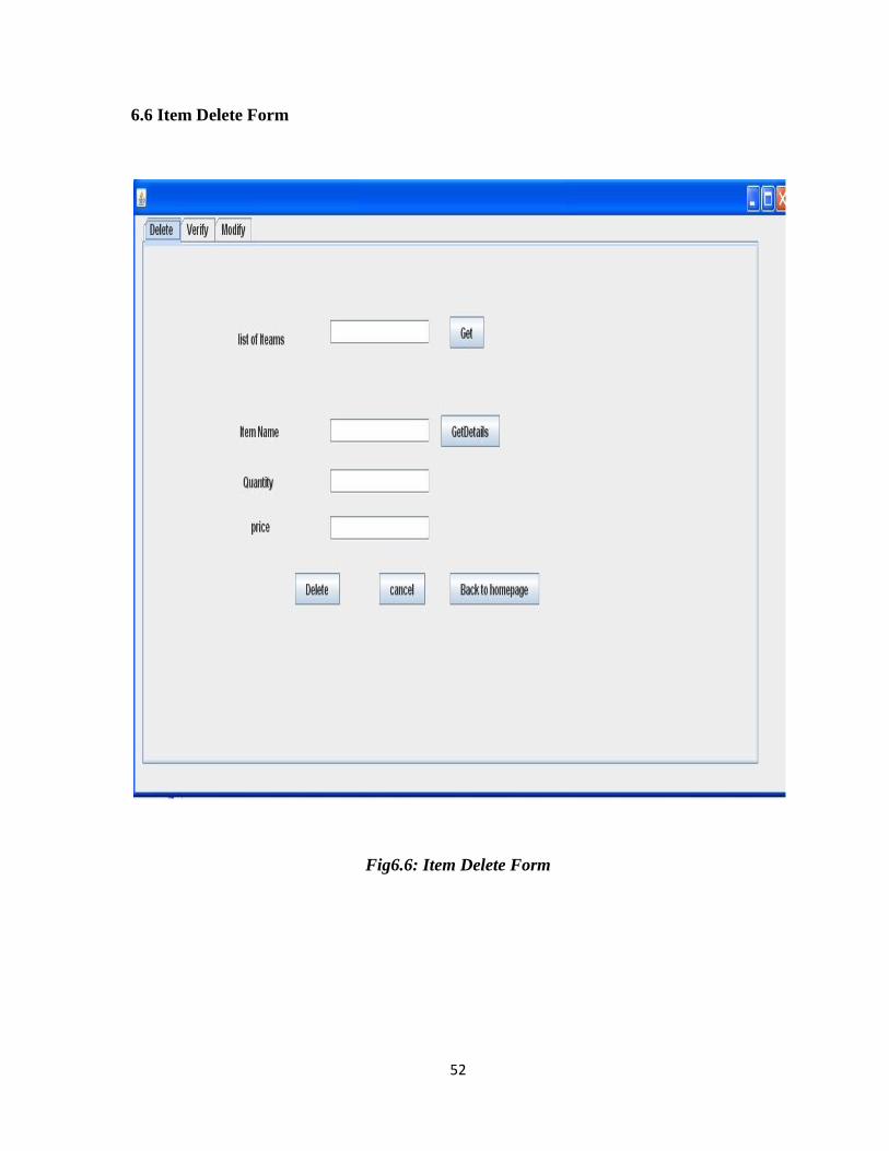
6.6 Item Delete Form
Fig6.6: Item Delete Form
53
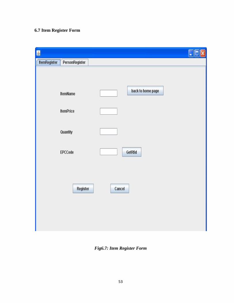
6.7 Item Register Form
Fig6.7: Item Register Form
54
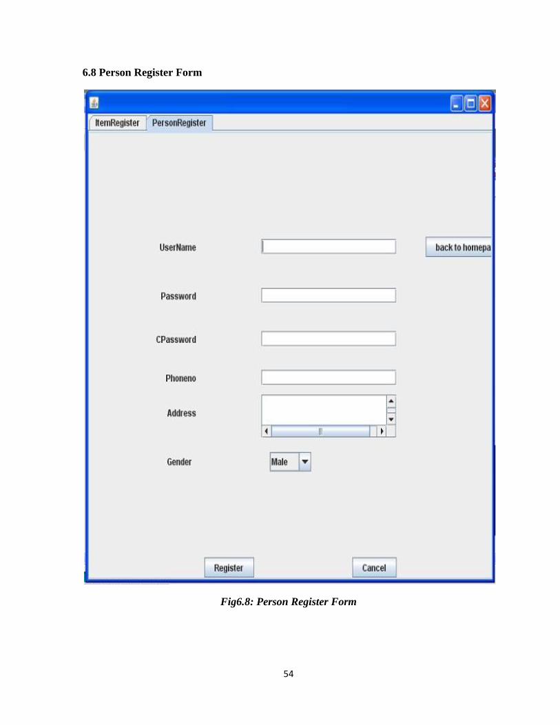
6.8 Person Register Form
Fig6.8: Person Register Form

55
6.9 MOBILE SCREEN SHOTS
6.9Mobile Main Form 6.10Mobile Login Form
Fig6.9: Mobile Main Form Fig6.10:Mobile Login Form

56
6.11 Item View Form 6.12Item Details Form
Fig6.11:Item View Form Fig 6.12: Item Details Form

57
6.13 Cart Form 6.14Item View Pay Form
Fig6.13: Cart Form Fig 6.14: Items View Pay Form
58
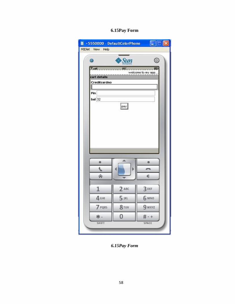
6.15Pay Form
6.15Pay Form

59
7. TESTING
A process of executing a program with the explicit intention of finding errors, that is
making the program fail.
SOFTWARE TESTING
It is the process of testing the functionality and correctness of software by running it.
Process of executing a program with the intent of finding an error
A good test case is one that has a high probability of finding an as yet undiscovered
error. A successful test is one that uncovers an as yet undiscovered error.
Software Testing is usually performed for one of two reasons
• Defect detection
• Reliability estimation
BLACK BOX TESTING
Applies to software or module, tests functionality in terms of inputs and outputs at
Interfaces. Test reveals if the software is fully operational with reference to requirements
specification.
WHITE BOX TESTING
Knowing the internal working i.e. to test if all internal operation are performed
according to program structure and data structures.
7.1 TESTING OBJECTIVE
The main aim of testing is to uncover a host of errors, systematically and with
minimum effort and time. Starting formally, we can say, Testing is a process of executing a
program with the intent of finding an error. A successful test is one that uncovers an as yet
undiscovered error.
As he good test case is one that has a high probability of finding errors, if it exists.
But there is one thing that testing cannot do testing cannot show the absence of defects it can
only show that software defects are present.
As the test results are gathered and evaluated they begin to give a qualitative
indication of the reliability of the software. If servers’ errors are detected, the overall quality
of the software is a natural suspect. If, on the other hand, all the errors, which are
encountered, are easily modifiable, then one of the two conclusions can be made:

60
For the purpose of the current system we are assuming that in the event that errors
that are easily modifiable points to the later possibility, since repeating the entire testing
routine can be very time consuming. What we propose to do instead is to get it tested by one
or more persons who are not a part of the development team but is well versed with the
subject and with the concept of software testing. If we cannot detect any serious errors, it will
enable us to state with the more confidence that the software does actually conform to
expected standards.
7.1.1 TEST PLAN
The importance of software testing and its implementations cannot be
overemphasized. Software testing is a critical element of Software Quality Assurance and
represents the ultimate review of the specifications, design and coding.
7.1.2 TESTING METHODOLOGIES
In order to uncover the errors present in the different phases we have the concept of
levels of testing. The basic levels of testing are as shown below:
Fig 7.1.2:Various levels of Testing
TEST CASES
A strategy for software testing will begin in the following order
1. Unit testing
2. Integration testing
3. Validation testing
4. System testing

61
Unit Testing
It concentrates on each unit of the software as implemented in source code and is a
white box oriented. Using the component level design description as a guide, important
control paths are tested to uncover errors within the boundary of the module. In the unit
testing, the step can be conducted in parallel for multiple components.
Integration Testing
Here focus is on design and construction of the software architecture. Integration
testing is a systematic technique for constructing the program structure while at the same
time conducting test to uncover errors associated with interfacing. The objective is to take
unit tested components and build a program structure that has been dictated by design.
Validation Testing
In this requirements established as part of software requirements analysis are
validated against the software that has been constructed i.e., validation succeeds when
software function in a manner that can be reasonably expected by the customer.+
System Testing
Is the menu bar displayed in the appropriate contested some system related features
included either in menus or tools? Do pull –Down menu operation and Tool-bars work
properly? Are all menu function and pull down sub function properly listed?; Is it possible to
invoke each menu function using a logical assumptions that if all parts of the system are
correct, the goal will be successfully achieved .? In adequate testing or non-testing will leads
to errors that may appear few months later.
This creates two problems:
Time delay between the cause and appearance of the problem.
The effect of the system errors on files and records within the system.
The purpose of the system testing is to consider all the likely variations to which it will be
suggested and push the systems to limits.
The testing process focuses on the logical intervals of the software ensuring that all
statements have been tested and on functional interval is conducting tests to uncover errors
and ensure that defined input will produce actual results that agree with the required results.
Program level testing, modules level testing integrated and carried out.

62
7.2 TEST CASE:
Table 7.2: Test Case1
Test
case
ID
Test Case
Name
Test Case Description Expected
Value
Actual Value Result
1 User
Registration
1. Run the
application.
2.All the fields should
be filled
1. Value must
be taken.
2. Next page
should be
displayed
1. Value must
be taken.
2.Next page
should be
displayed
Pass
2 Product
Search
1. Run the application 1. Option must
be taken.
2. Next page
should be
displayed
1.Option
must be
taken.
2. Next page
should be
displayed
Pass
3 Admin
Insert
1. Run the application 1. All the
values should
be inserted.
2.Data should
be stored in
Database
1. All the
values should
be inserted.
2.Data should
be stored in
Database
Pass
4 Bill
Payment
1. Run the application 1. Credit card
number and
pin number
should be
taken
1.Credit card
and pin
number
should be
valid
Pass
Test
case
ID
Test Case
Name
Test Case Description Expected
Value
Actual Value Result

63
7.3 Item Register Validation:
Fig7.3: Item Register Validation

64
7.4 Person Register Validate:
Fig7.4: Person Register Validation

65
CONCLUSION
Integrated Shopping application with mobile as domain is successfully implemented
with all the features mentioned in the SRS. The project to a huge extent simplifies the
process of obtaining information whenever a RFID Readers enabled device request
information.
The software thus developed has been implemented successfully which has been
under observation for the past few days. Various tests have been performed to scrutinize the
validation of each data and the errors were stopped out and then finally cleared in a
sophisticated manner.
Even though the software has many advantages, some limitations also exists which
are meager and negligible. Those limitations need not be considered since it does not affect
the system as a whole. An attempt is made to maintain maximum perfection in documenting
the software in a simple, precise and in a self explanatory manner.

66
FUTURE ENHANCEMENTS
Further enhancement is the part, which tells that what changes can be done in the
future to meet the challenges. It also tells what are the parts that have to be changed to meet
the challenges that may arise in near future.
The project “INTEGRATED SHOPPING” has been done taking into consideration
all the factors of SRS and without any room for redundancy. There are some aspects which
can be further updated or modified in future if the changes are required. The enhancements
may be like we can add the all items in home to the system which guides the customer which
way to go for the product that they have searched for. The user has the freedom to change the
software according to the needs.
67
BIBLIOGRAPHY
Bruce Eckel, Thinking in Java Third Edition, Publisher: Pearson Education.
Herbert Schildt,The Complete Reference to Java 2, Publisher: Tata McGraw-Hill.
Roger S. Pressman, Software Engineering-A practitioner’s approach, Publisher:
Tata McGraw-Hill.
Grady Booch, James Rumbaing, Ivar Jacobson, The Unified Modelling Language
User Guide, Publisher: Pearson Education.
Martin Fowler & Scott, UML Distilled Second Edition, Publisher Pearson
education
Michael Morrison, Wireless Java with J2ME, Publisher Tec media