Embed Size (px)
Citation preview
JURUSAN SISTEM INFORMASIFakultas Teknologi Informasi - ITS
KS141309DESAIN BASIS DATA
Pokok Bahasan 3aDesain Basis Data KonseptualMenggunakan ER Modeling
Prof. Ir. Arif Djunaidy, M.Sc., [email protected]@gmail.com
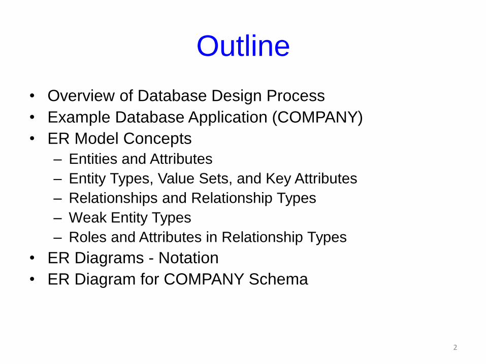
Outline
• Overview of Database Design Process
• Example Database Application (COMPANY)
• ER Model Concepts
– Entities and Attributes
– Entity Types, Value Sets, and Key Attributes
– Relationships and Relationship Types
– Weak Entity Types
– Roles and Attributes in Relationship Types
• ER Diagrams - Notation
• ER Diagram for COMPANY Schema
2
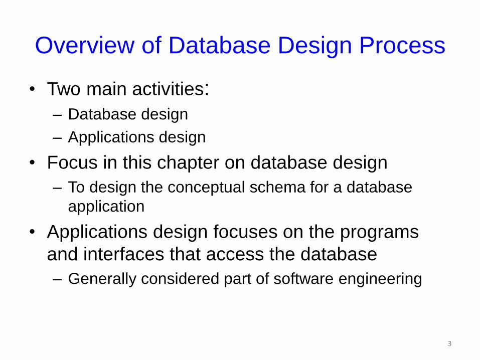
Overview of Database Design Process
• Two main activities:– Database design
– Applications design
• Focus in this chapter on database design
– To design the conceptual schema for a database
application
• Applications design focuses on the programs
and interfaces that access the database
– Generally considered part of software engineering
3
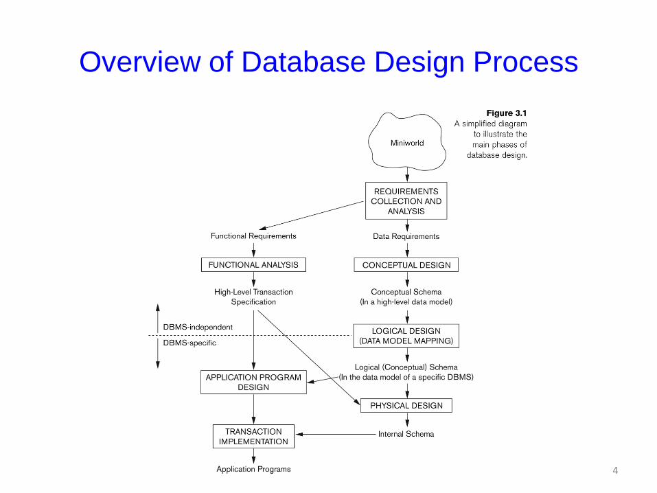
Overview of Database Design Process
4
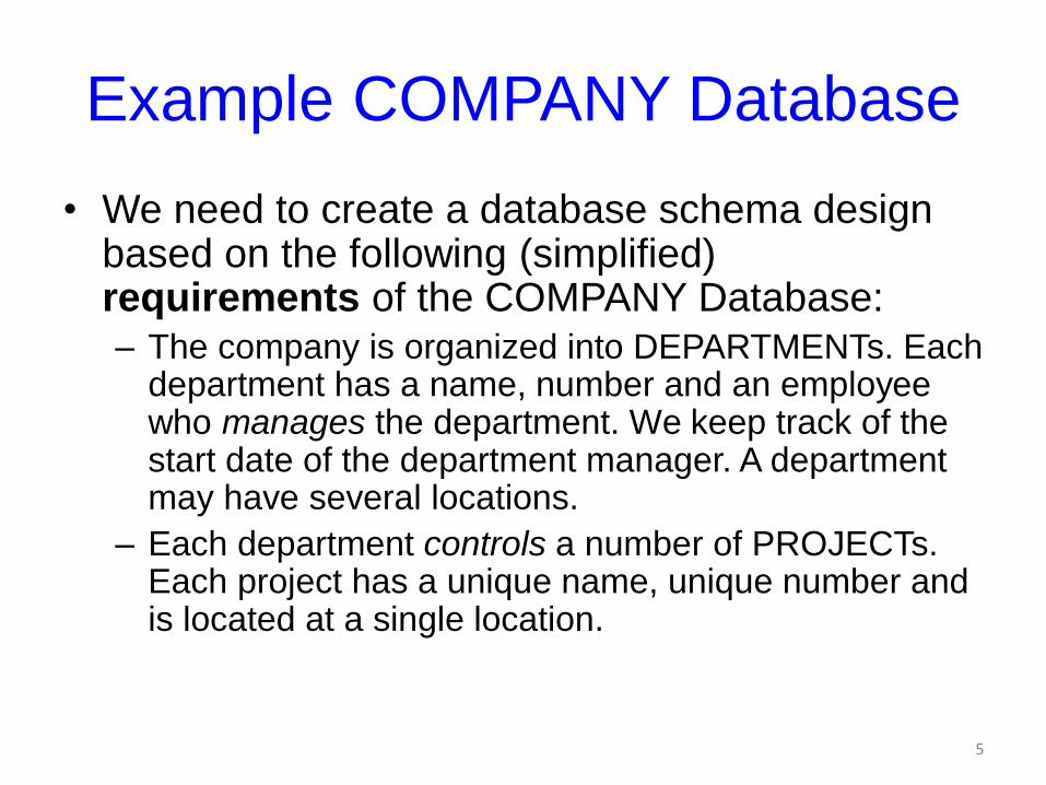
Example COMPANY Database
• We need to create a database schema design based on the following (simplified) requirements of the COMPANY Database:– The company is organized into DEPARTMENTs. Each
department has a name, number and an employee who manages the department. We keep track of the start date of the department manager. A department may have several locations.
– Each department controls a number of PROJECTs. Each project has a unique name, unique number and is located at a single location.
5
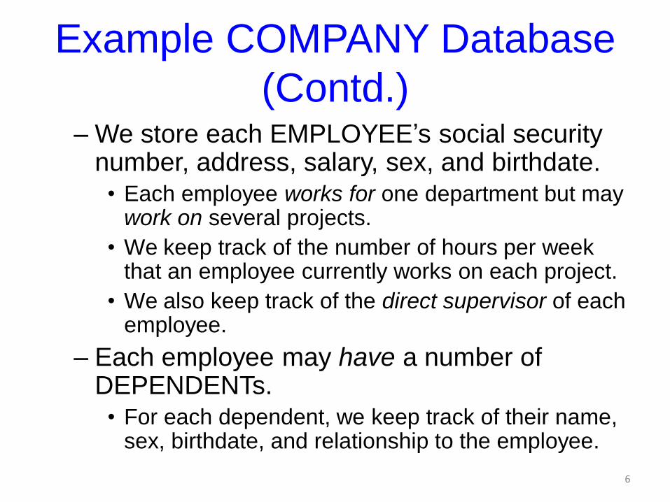
Example COMPANY Database
(Contd.)– We store each EMPLOYEE’s social security
number, address, salary, sex, and birthdate. • Each employee works for one department but may
work on several projects.
• We keep track of the number of hours per week that an employee currently works on each project.
• We also keep track of the direct supervisor of each employee.
– Each employee may have a number of DEPENDENTs.
• For each dependent, we keep track of their name, sex, birthdate, and relationship to the employee.
6
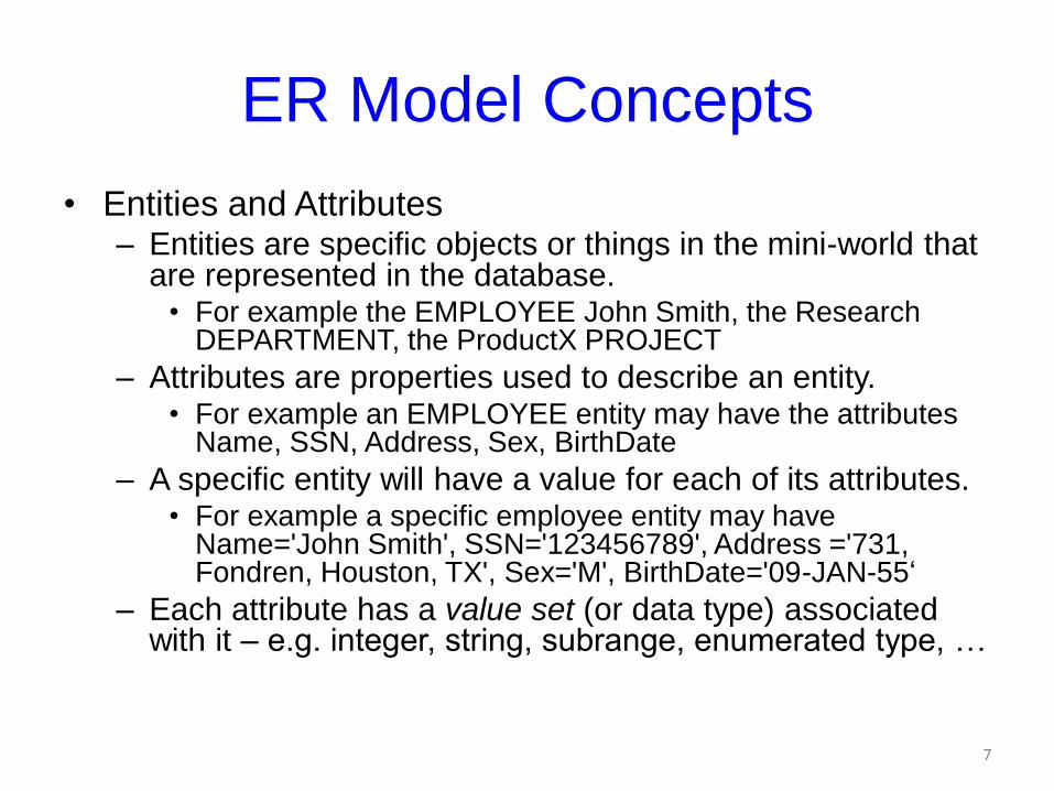
ER Model Concepts
• Entities and Attributes– Entities are specific objects or things in the mini-world that
are represented in the database.• For example the EMPLOYEE John Smith, the Research
DEPARTMENT, the ProductX PROJECT
– Attributes are properties used to describe an entity.• For example an EMPLOYEE entity may have the attributes
Name, SSN, Address, Sex, BirthDate
– A specific entity will have a value for each of its attributes.• For example a specific employee entity may have
Name='John Smith', SSN='123456789', Address ='731, Fondren, Houston, TX', Sex='M', BirthDate='09-JAN-55‘
– Each attribute has a value set (or data type) associated with it – e.g. integer, string, subrange, enumerated type, …
7
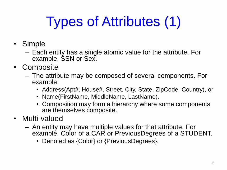
Types of Attributes (1)
• Simple– Each entity has a single atomic value for the attribute. For
example, SSN or Sex.
• Composite– The attribute may be composed of several components. For
example:• Address(Apt#, House#, Street, City, State, ZipCode, Country), or
• Name(FirstName, MiddleName, LastName).
• Composition may form a hierarchy where some components are themselves composite.
• Multi-valued– An entity may have multiple values for that attribute. For
example, Color of a CAR or PreviousDegrees of a STUDENT.• Denoted as {Color} or {PreviousDegrees}.
8
Types of Attributes (2)
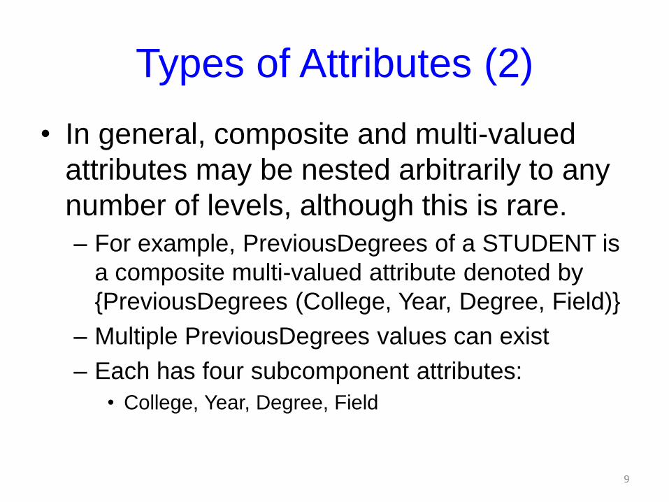
• In general, composite and multi-valued
attributes may be nested arbitrarily to any
number of levels, although this is rare.
– For example, PreviousDegrees of a STUDENT is
a composite multi-valued attribute denoted by
{PreviousDegrees (College, Year, Degree, Field)}
– Multiple PreviousDegrees values can exist
– Each has four subcomponent attributes:
• College, Year, Degree, Field
9
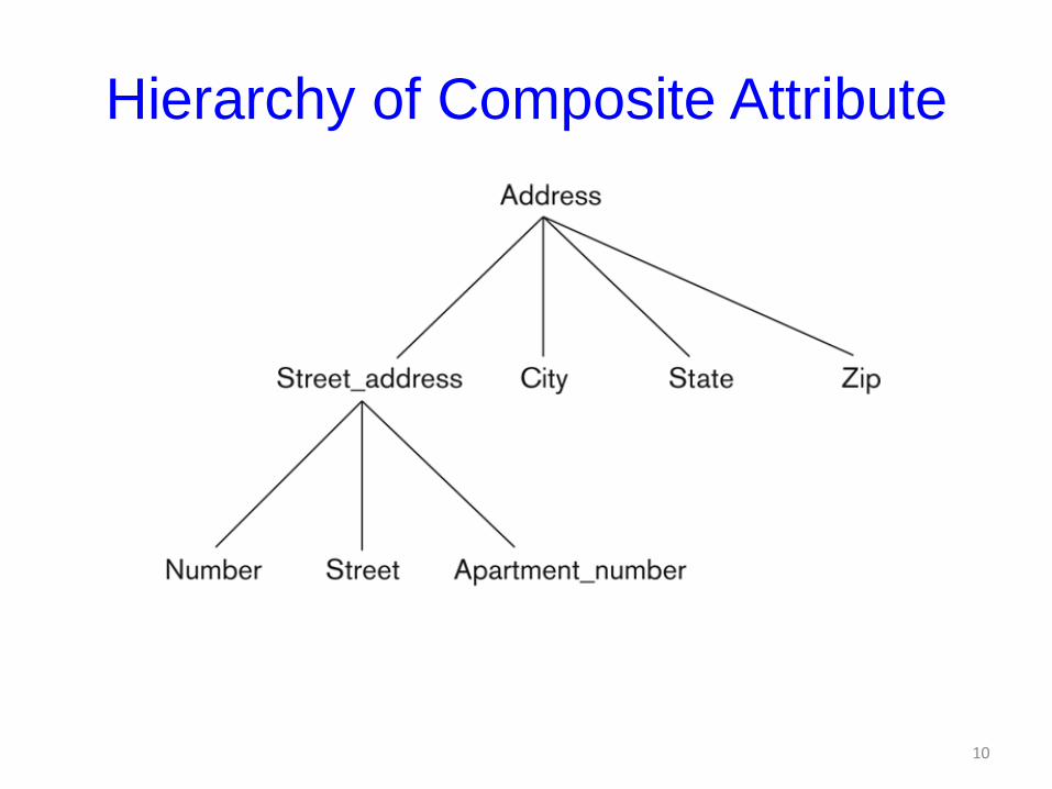
Hierarchy of Composite Attribute
10
Entity Types and Key Attributes (1)
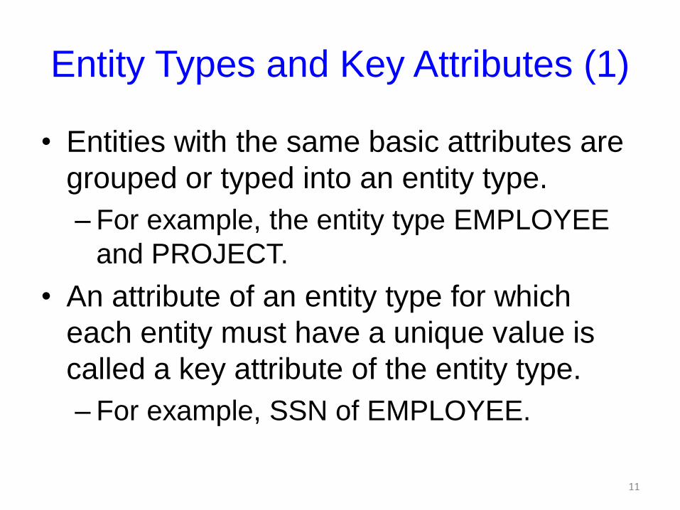
• Entities with the same basic attributes are
grouped or typed into an entity type.
– For example, the entity type EMPLOYEE
and PROJECT.
• An attribute of an entity type for which
each entity must have a unique value is
called a key attribute of the entity type.
– For example, SSN of EMPLOYEE.
11
Entity Types and Key Attributes (2)
• A key attribute may be composite.
– VehicleTagNumber is a key of the CAR entity
type with components (Number, State).
• An entity type may have more than one
key.
– The CAR entity type may have two keys:
• VehicleIdentificationNumber (popularly called VIN)
• VehicleTagNumber (Number, State), aka license
plate number.
• Each key is underlined12
Displaying an Entity type
• In ER diagrams, an entity type is displayed in a rectangular box
• Attributes are displayed in ovals– Each attribute is connected to its entity type
– Components of a composite attribute are connected to the oval representing the composite attribute
– Each key attribute is underlined
– Multivalued attributes displayed in double ovals
• See CAR example on next slide
13
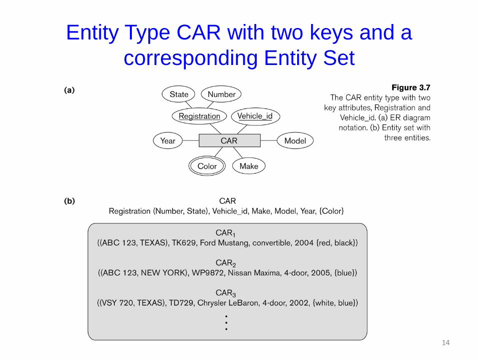
Entity Type CAR with two keys and a
corresponding Entity Set
14
Entity Set
• Each entity type will have a collection of
entities stored in the database
– Called the entity set
• Previous slide shows three CAR entity
instances in the entity set for CAR
• Same name (CAR) used to refer to both
the entity type and the entity set
• Entity set is the current state of the entities
of that type that are stored in the database15
Initial Design of Entity Types for
the COMPANY Database Schema• Based on the requirements, we can identify four
initial entity types in the COMPANY database:
– DEPARTMENT
– PROJECT
– EMPLOYEE
– DEPENDENT
• Their initial design is shown on the following
slide
• The initial attributes shown are derived from the
requirements description
16
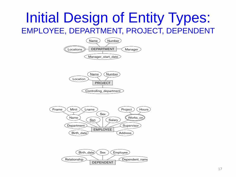
Initial Design of Entity Types:EMPLOYEE, DEPARTMENT, PROJECT, DEPENDENT
17
Refining the initial design by introducing
relationships
• The initial design is typically not complete
• Some aspects in the requirements will be
represented as relationships
• ER model has three main concepts:
– Entities (and their entity types and entity sets)
– Attributes (simple, composite, multivalued)
– Relationships (and their relationship types
and relationship sets)
• We introduce relationship concepts next18
Relationships and Relationship Types (1)
• A relationship relates two or more distinct entities with a specific meaning.– For example, EMPLOYEE John Smith works on the ProductX
PROJECT, or EMPLOYEE Franklin Wong manages the Research DEPARTMENT.
• Relationships of the same type are grouped or typed into a relationship type.– For example, the WORKS_ON relationship type in which
EMPLOYEEs and PROJECTs participate, or the MANAGES relationship type in which EMPLOYEEs and DEPARTMENTs participate.
• The degree of a relationship type is the number of participating entity types. – Both MANAGES and WORKS_ON are binary relationships.
19
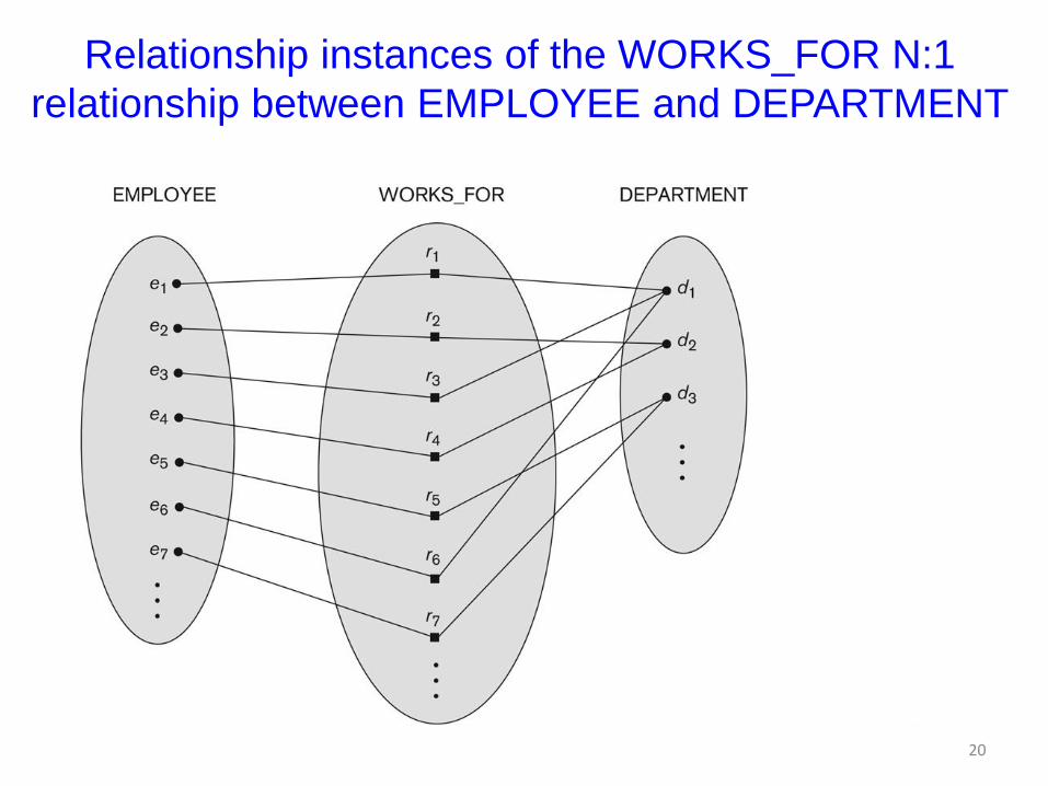
Relationship instances of the WORKS_FOR N:1
relationship between EMPLOYEE and DEPARTMENT
20
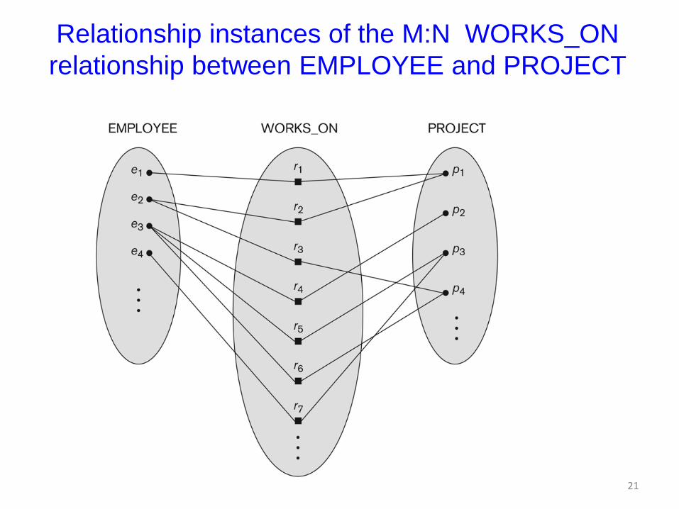
Relationship instances of the M:N WORKS_ON
relationship between EMPLOYEE and PROJECT
21
Relationship type vs. relationship set (1)
• Relationship Type:
– Is the schema description of a relationship
– Identifies the relationship name and the
participating entity types
– Also identifies certain relationship constraints
• Relationship Set:
– The current set of relationship instances
represented in the database
– The current state of a relationship type
22
Relationship type vs. relationship set (2)
• Previous figures displayed the relationship sets
• Each instance in the set relates individual
participating entities – one from each
participating entity type
• In ER diagrams, we represent the relationship
type as follows:
– Diamond-shaped box is used to display a relationship
type
– Connected to the participating entity types via straight
lines
23
Refining the COMPANY database schema
by introducing relationships
• By examining the requirements, six relationship types
are identified
• All are binary relationships( degree 2)
• Listed below with their participating entity types:
– WORKS_FOR (between EMPLOYEE, DEPARTMENT)
– MANAGES (also between EMPLOYEE, DEPARTMENT)
– CONTROLS (between DEPARTMENT, PROJECT)
– WORKS_ON (between EMPLOYEE, PROJECT)
– SUPERVISION (between EMPLOYEE (as subordinate),
EMPLOYEE (as supervisor))
– DEPENDENTS_OF (between EMPLOYEE, DEPENDENT)
24
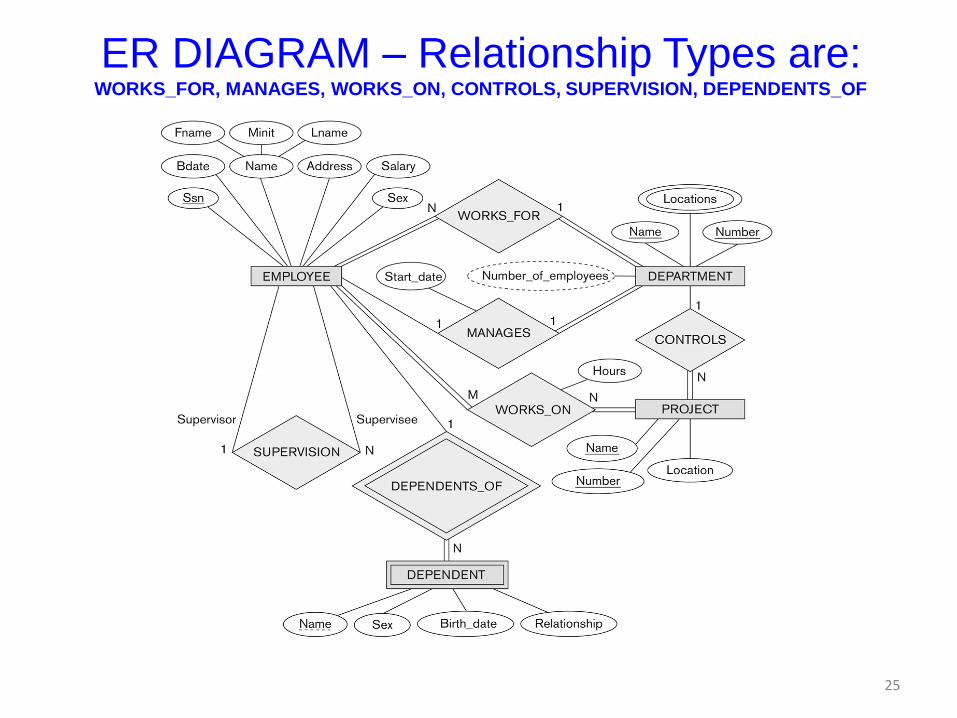
ER DIAGRAM – Relationship Types are:WORKS_FOR, MANAGES, WORKS_ON, CONTROLS, SUPERVISION, DEPENDENTS_OF
25
Discussion on Relationship Types
• In the refined design, some attributes from the initial
entity types are refined into relationships:
– Manager of DEPARTMENT -> MANAGES
– Works_on of EMPLOYEE -> WORKS_ON
– Department of EMPLOYEE -> WORKS_FOR
– etc
• In general, more than one relationship type can exist
between the same participating entity types
– MANAGES and WORKS_FOR are distinct relationship
types between EMPLOYEE and DEPARTMENT
– Different meanings and different relationship instances.
26
Recursive Relationship Type
• An relationship type whose with the same participating
entity type in distinct roles
• Example: the SUPERVISION relationship
• EMPLOYEE participates twice in two distinct roles:
– supervisor (or boss) role
– supervisee (or subordinate) role
• Each relationship instance relates two distinct
EMPLOYEE entities:
– One employee in supervisor role
– One employee in supervisee role
27
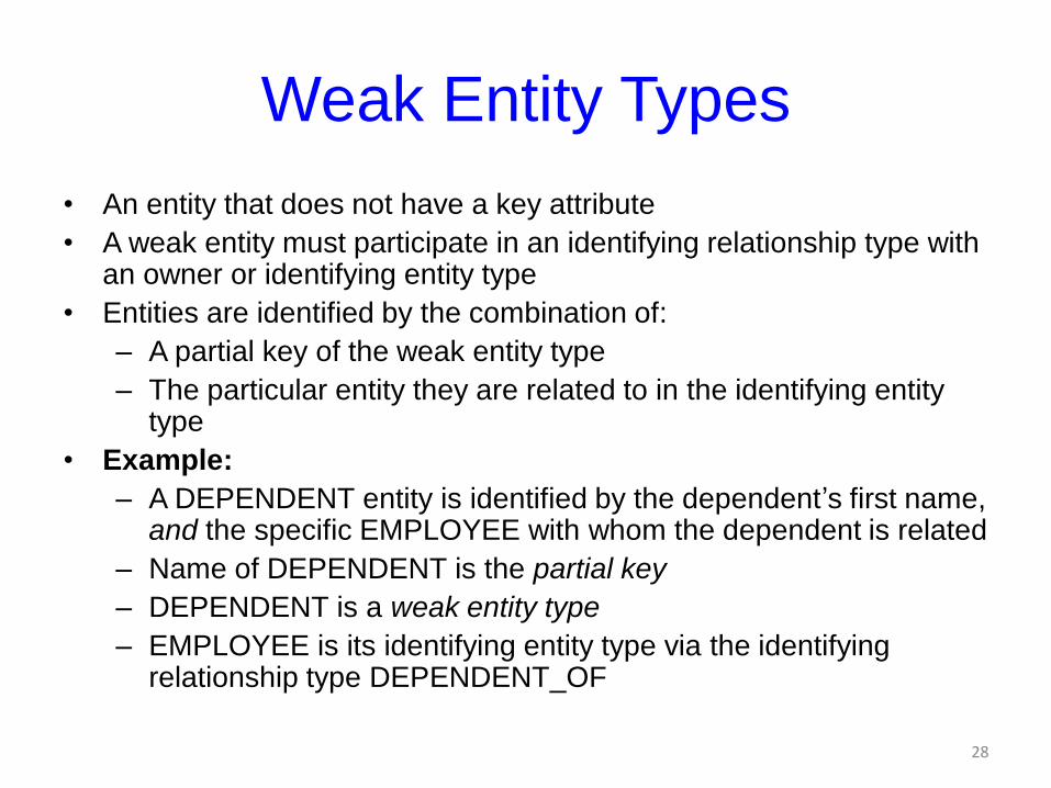
Weak Entity Types
• An entity that does not have a key attribute
• A weak entity must participate in an identifying relationship type with an owner or identifying entity type
• Entities are identified by the combination of:
– A partial key of the weak entity type
– The particular entity they are related to in the identifying entity type
• Example:
– A DEPENDENT entity is identified by the dependent’s first name, and the specific EMPLOYEE with whom the dependent is related
– Name of DEPENDENT is the partial key
– DEPENDENT is a weak entity type
– EMPLOYEE is its identifying entity type via the identifying relationship type DEPENDENT_OF
28
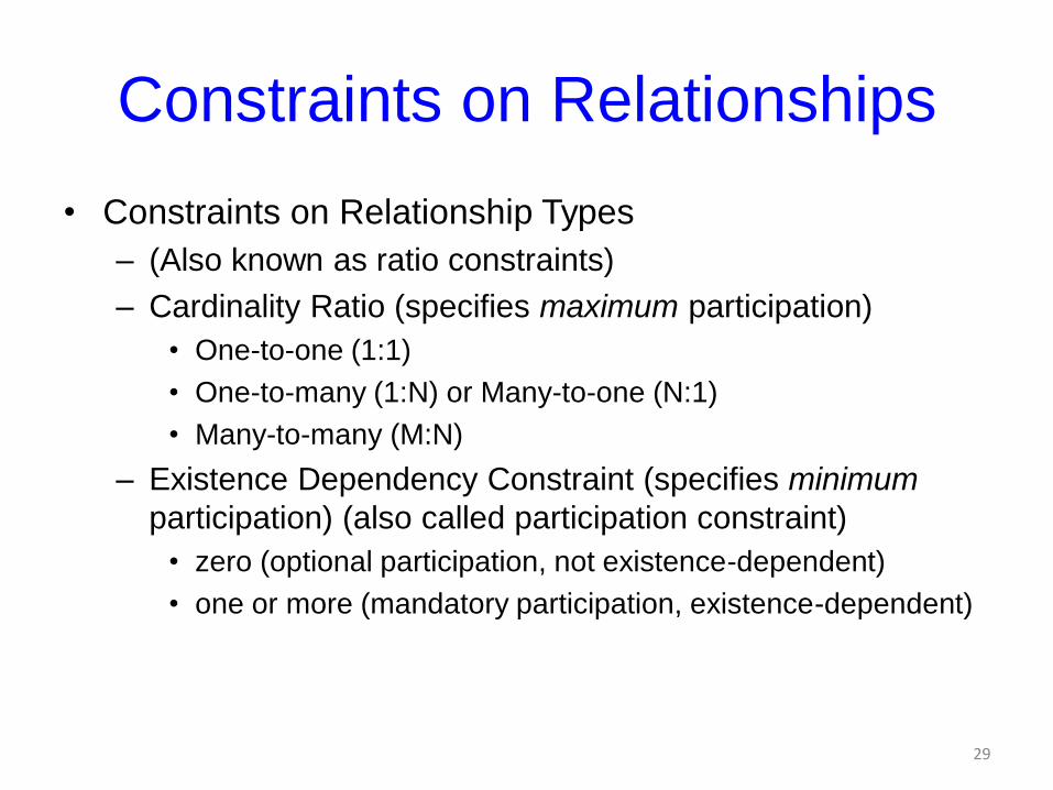
Constraints on Relationships
• Constraints on Relationship Types
– (Also known as ratio constraints)
– Cardinality Ratio (specifies maximum participation)
• One-to-one (1:1)
• One-to-many (1:N) or Many-to-one (N:1)
• Many-to-many (M:N)
– Existence Dependency Constraint (specifies minimum
participation) (also called participation constraint)
• zero (optional participation, not existence-dependent)
• one or more (mandatory participation, existence-dependent)
29
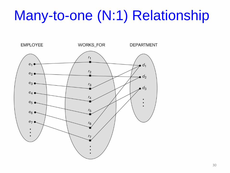
Many-to-one (N:1) Relationship
30
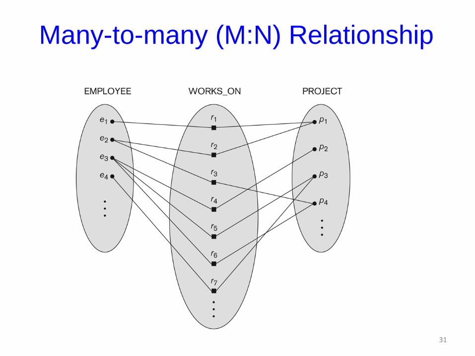
Many-to-many (M:N) Relationship
31
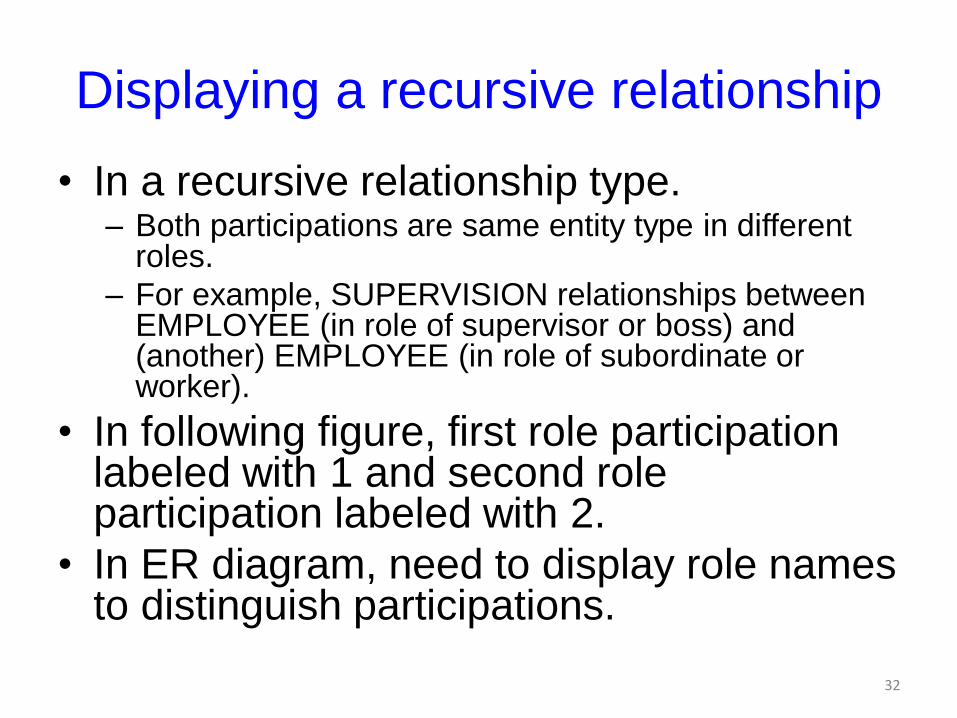
Displaying a recursive relationship
• In a recursive relationship type.– Both participations are same entity type in different
roles.
– For example, SUPERVISION relationships between EMPLOYEE (in role of supervisor or boss) and (another) EMPLOYEE (in role of subordinate or worker).
• In following figure, first role participation labeled with 1 and second role participation labeled with 2.
• In ER diagram, need to display role names to distinguish participations.
32
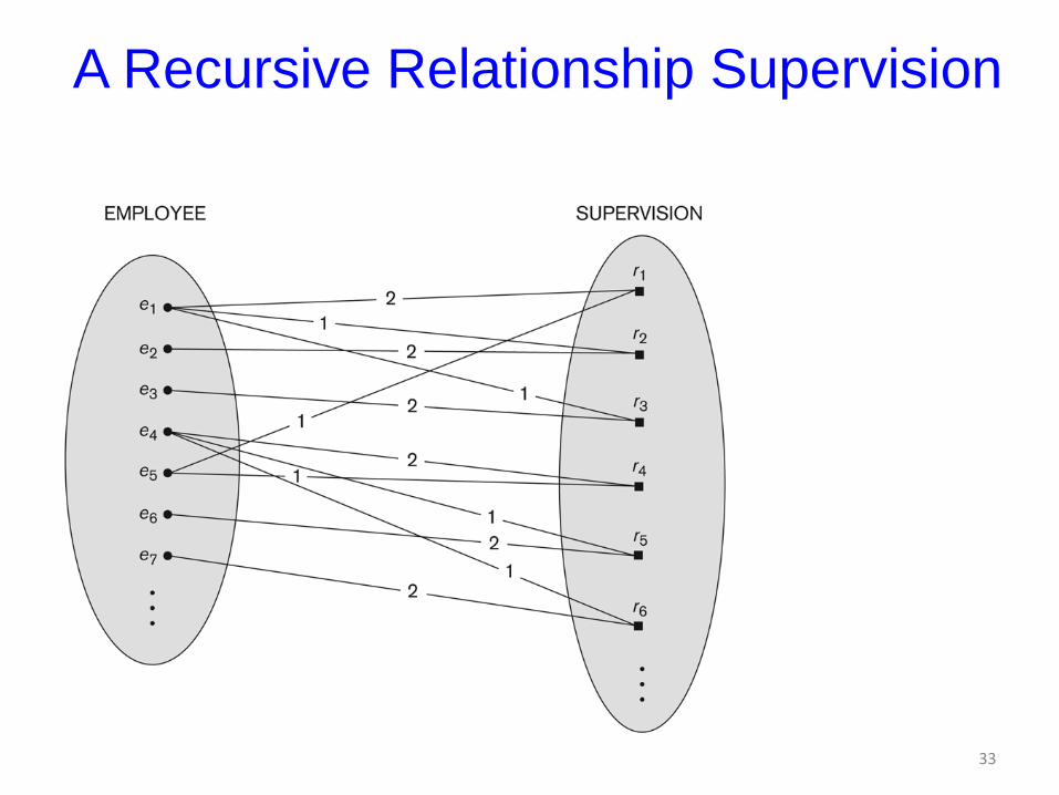
A Recursive Relationship Supervision
33
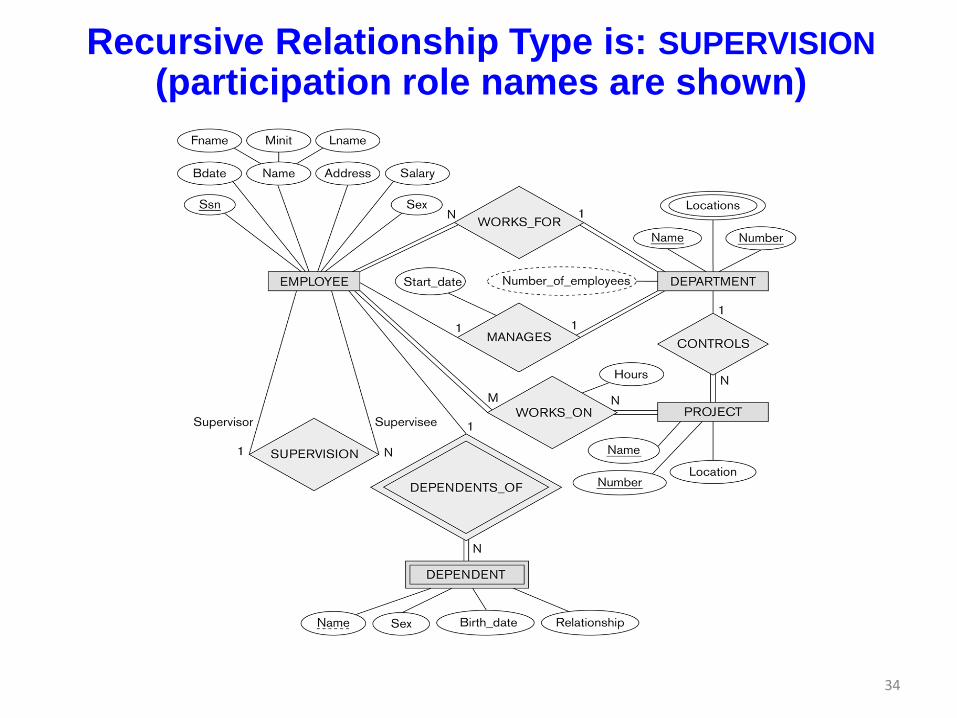
Recursive Relationship Type is: SUPERVISION
(participation role names are shown)
34
Attributes of Relationship types
• A relationship type can have attributes:
– For example, HoursPerWeek of WORKS_ON
– Its value for each relationship instance describes the number of hours per week that an EMPLOYEE works on a PROJECT.
• A value of HoursPerWeek depends on a particular (employee, project) combination
– Most relationship attributes are used with M:N relationships
• In 1:N relationships, they can be transferred to the entity type on the N-side of the relationship
35
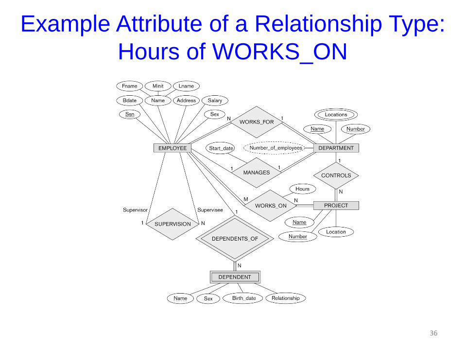
Example Attribute of a Relationship Type:
Hours of WORKS_ON
36
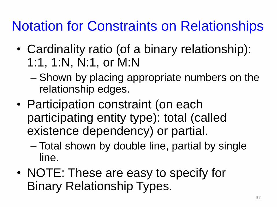
Notation for Constraints on Relationships
• Cardinality ratio (of a binary relationship): 1:1, 1:N, N:1, or M:N
– Shown by placing appropriate numbers on the relationship edges.
• Participation constraint (on each participating entity type): total (called existence dependency) or partial.
– Total shown by double line, partial by single line.
• NOTE: These are easy to specify for Binary Relationship Types.
37
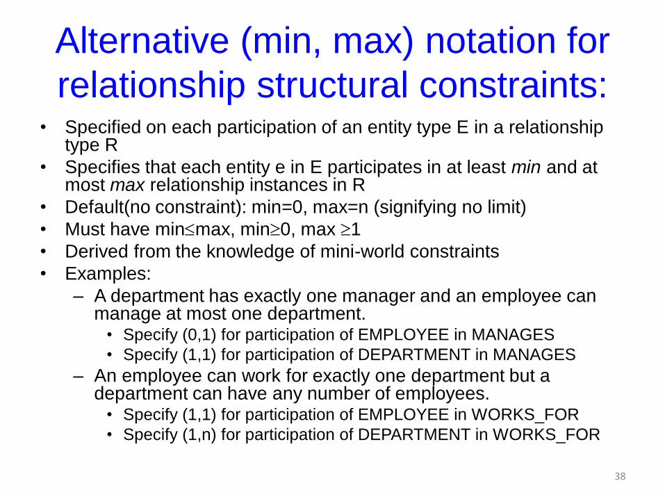
Alternative (min, max) notation for
relationship structural constraints:• Specified on each participation of an entity type E in a relationship
type R
• Specifies that each entity e in E participates in at least min and at most max relationship instances in R
• Default(no constraint): min=0, max=n (signifying no limit)
• Must have minmax, min0, max 1
• Derived from the knowledge of mini-world constraints
• Examples:
– A department has exactly one manager and an employee can manage at most one department.
• Specify (0,1) for participation of EMPLOYEE in MANAGES
• Specify (1,1) for participation of DEPARTMENT in MANAGES
– An employee can work for exactly one department but a department can have any number of employees.
• Specify (1,1) for participation of EMPLOYEE in WORKS_FOR
• Specify (1,n) for participation of DEPARTMENT in WORKS_FOR
38
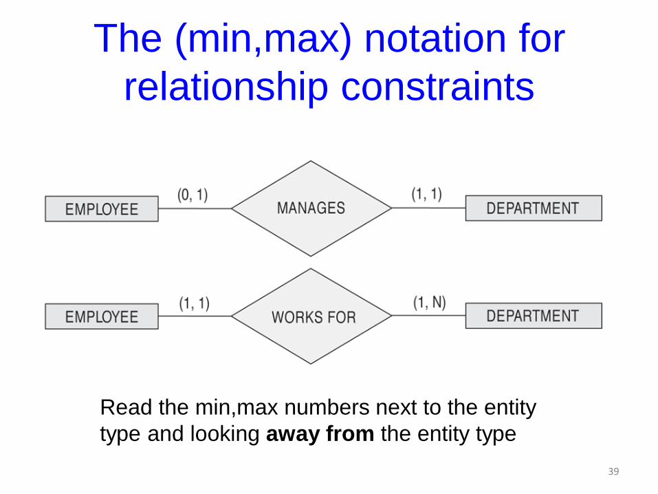
The (min,max) notation for
relationship constraints
Read the min,max numbers next to the entity
type and looking away from the entity type
39
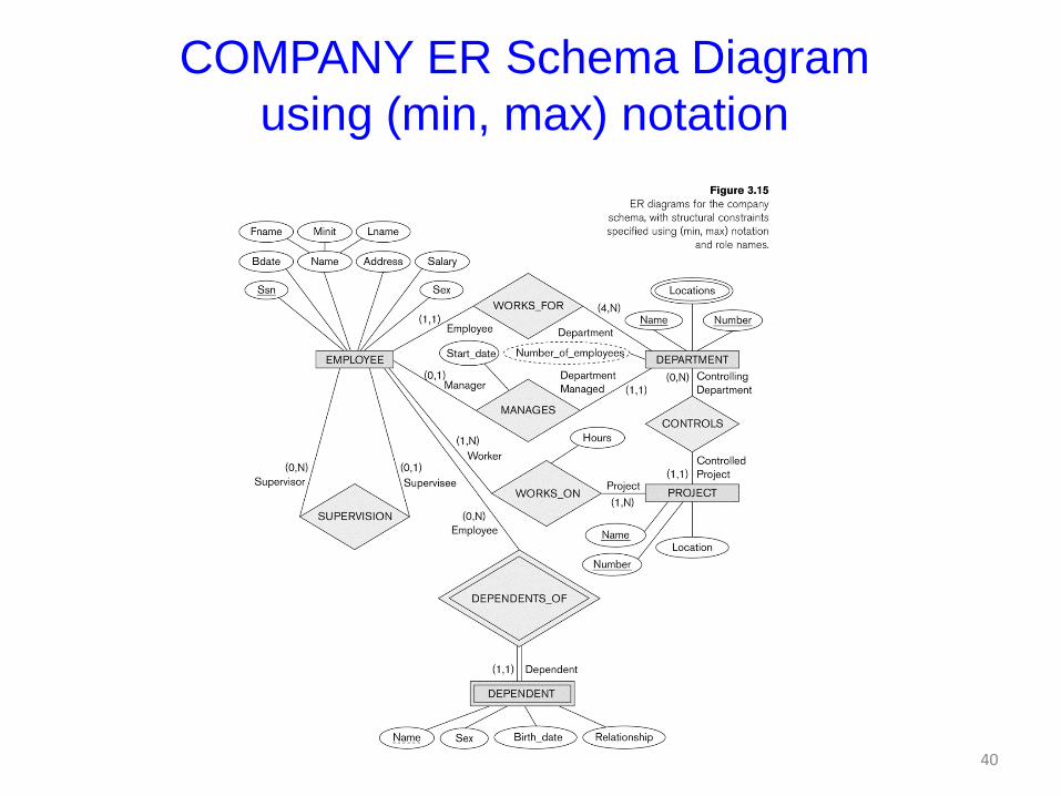
COMPANY ER Schema Diagram
using (min, max) notation
40
Alternative diagrammatic notation
• ER diagrams is one popular example for
displaying database schemas
• Many other notations exist in the literature and in
various database design and modeling tools
• Appendix A illustrates some of the alternative
notations that have been used
• UML class diagrams is representative of another
way of displaying ER concepts that is used in
several commercial design tools
41
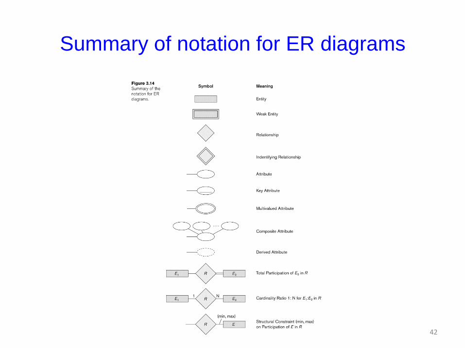
Summary of notation for ER diagrams
42
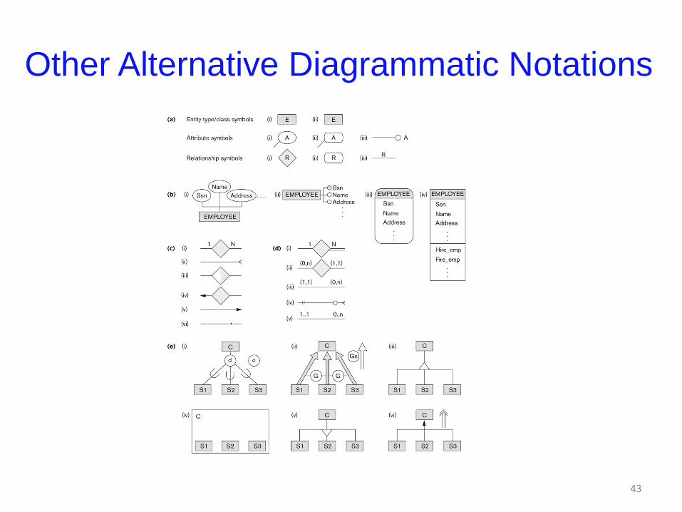
Other Alternative Diagrammatic Notations
43
Relationships of Higher Degree
• Relationship types of degree 2 are called
binary
• Relationship types of degree 3 are called
ternary and of degree n are called n-ary
• In general, an n-ary relationship is not
equivalent to n binary relationships
• Constraints are harder to specify for
higher-degree relationships (n > 2) than for
binary relationships
44
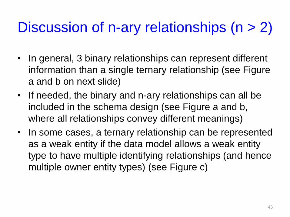
Discussion of n-ary relationships (n > 2)
• In general, 3 binary relationships can represent different
information than a single ternary relationship (see Figure
a and b on next slide)
• If needed, the binary and n-ary relationships can all be
included in the schema design (see Figure a and b,
where all relationships convey different meanings)
• In some cases, a ternary relationship can be represented
as a weak entity if the data model allows a weak entity
type to have multiple identifying relationships (and hence
multiple owner entity types) (see Figure c)
45
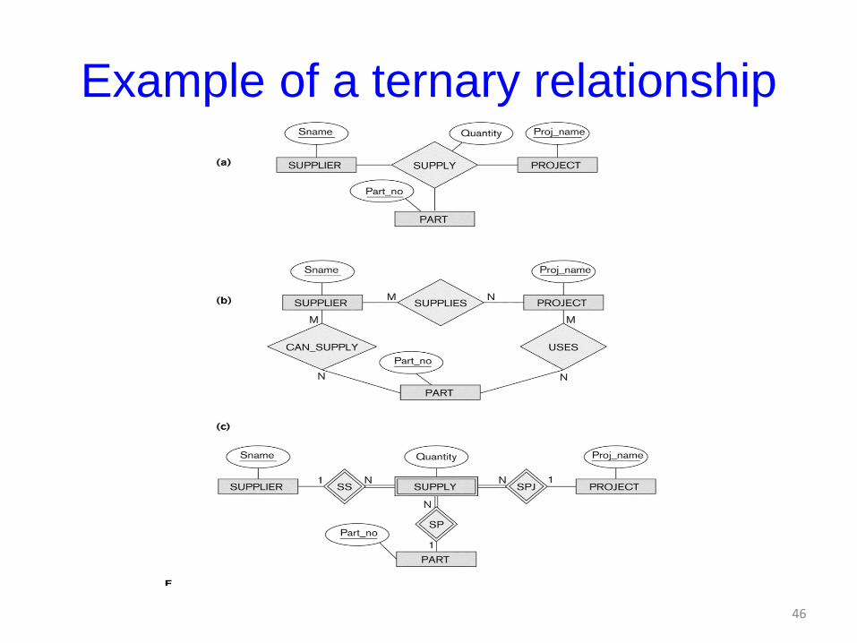
Example of a ternary relationship
46
Discussion of n-ary relationships (n > 2)
• If a particular binary relationship can be
derived from a higher-degree relationship
at all times, then it is redundant
• For example, the TAUGHT_DURING
binary relationship in Figure below (see
next slide) can be derived from the ternary
relationship OFFERS (based on the
meaning of the relationships)
47
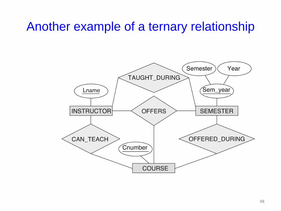
Another example of a ternary relationship
48
Displaying constraints on
higher-degree relationships
• The (min, max) constraints can be displayed on the
edges – however, they do not fully describe the
constraints
• Displaying a 1, M, or N indicates additional constraints
– An M or N indicates no constraint
– A 1 indicates that an entity can participate in at most one
relationship instance that has a particular combination of
the other participating entities
• In general, both (min, max) and 1, M, or N are needed to
describe fully the constraints
49
Data Modeling Tools
• A number of popular tools that cover conceptual modeling and mapping into relational schema design.
– Examples: ERWin, S- Designer (Enterprise Application Suite), ER- Studio, etc.
• POSITIVES:
– Serves as documentation of application requirements, easy user interface - mostly graphics editor support
• NEGATIVES:
– Most tools lack a proper distinct notation for relationships with relationship attributes
– Mostly represent a relational design in a diagrammatic form rather than a conceptual ER-based design
50
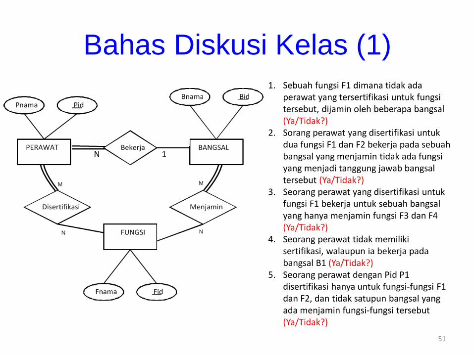
Bahas Diskusi Kelas (1)1. Sebuah fungsi F1 dimana tidak ada
perawat yang tersertifikasi untuk fungsi tersebut, dijamin oleh beberapa bangsal (Ya/Tidak?)
2. Sorang perawat yang disertifikasi untuk dua fungsi F1 dan F2 bekerja pada sebuah bangsal yang menjamin tidak ada fungsi yang menjadi tanggung jawab bangsal tersebut (Ya/Tidak?)
3. Seorang perawat yang disertifikasi untuk fungsi F1 bekerja untuk sebuah bangsal yang hanya menjamin fungsi F3 dan F4 (Ya/Tidak?)
4. Seorang perawat tidak memiliki sertifikasi, walaupun ia bekerja pada bangsal B1 (Ya/Tidak?)
5. Seorang perawat dengan Pid P1 disertifikasi hanya untuk fungsi-fungsi F1 dan F2, dan tidak satupun bangsal yang ada menjamin fungsi-fungsi tersebut (Ya/Tidak?)
1N
51
Bahas Diskusi Kelas (2)
Dengan menggunakan notasi yang dibahas dalam kuliah, gambarkan Diagram ER untuk kasus kecil berikut yang berkaitan dengan sebagian kecil basis data perusahaan manufaktur.– Basis data berisikan informasi mengenai pegawai,
pabrik, dan produk.
– Setiap pegawai mempunyai nomor pegawai (NPeg), nama dan gaji. Seorang pegawai diidentifikasi secara unik berdasarkan NPeg.
– Setiap pabrik mempunyai sebuah nomor ID, nama dan bujet. Nomor ID mengidentifikasi sebuah pabrik dengan unik.
52
Bahas Diskusi Kelas (2) - lanjutan)
– Setiap produk juga mempunyai ID dan nama. Nomor ID mengidentifikasi sebuah produk secara unik.
– Setiap pegawai (bawahan) harus melaporkan paling banyak ke seorang pegawai lain (sebagai atasan langsung).
– Setiap pegawai boleh bekerja paling sedikit di satu pabrik.
– Setiap produk dipabrikasi di tepat satu pabrik.
– Setiap produk dapat merupakan komponen dari beberapa produk lainnya.
53
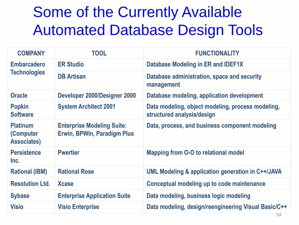
Some of the Currently Available
Automated Database Design Tools
COMPANY TOOL FUNCTIONALITY
Embarcadero
Technologies
ER Studio Database Modeling in ER and IDEF1X
DB Artisan Database administration, space and security
management
Oracle Developer 2000/Designer 2000 Database modeling, application development
Popkin
Software
System Architect 2001 Data modeling, object modeling, process modeling,
structured analysis/design
Platinum
(Computer
Associates)
Enterprise Modeling Suite:
Erwin, BPWin, Paradigm Plus
Data, process, and business component modeling
Persistence
Inc.
Pwertier Mapping from O-O to relational model
Rational (IBM) Rational Rose UML Modeling & application generation in C++/JAVA
Resolution Ltd. Xcase Conceptual modeling up to code maintenance
Sybase Enterprise Application Suite Data modeling, business logic modeling
Visio Visio Enterprise Data modeling, design/reengineering Visual Basic/C++54
Extended Entity-Relationship
(EER) Model (in next chapter)
• The entity relationship model in its original
form did not support the specialization and
generalization abstractions
• Next chapter illustrates how the ER model
can be extended with
– Type-subtype and set-subset relationships
– Specialization/Generalization Hierarchies
– Notation to display them in EER diagrams55
Summary
• ER Model Concepts: Entities, attributes,
relationships
• Constraints in the ER model
• Using ER in step-by-step conceptual
schema design for the COMPANY
database
• ER Diagrams - Notation
• Alternative Notations – UML class
diagrams, others56

AKHIR POKOK BAHASAN 3A
57