Embed Size (px)
DESCRIPTION
Parallel sysplex
Citation preview
ibm.com/redbooks
Front cover
IBM z/OS Parallel SysplexOperational Scenarios
Frank KynePeter Cottrell
Christian DelignyGavin FosterRobert HainRoger Lowe
Charles MacNivenFeroni Suhood
Understanding Parallel Sysplex
Handbook for sysplex management
Operations best practices

International Technical Support Organization
IBM z/OS Parallel Sysplex Operational Scenarios
May 2009
SG24-2079-01
© Copyright International Business Machines Corporation 2009. All rights reserved.Note to U.S. Government Users Restricted Rights -- Use, duplication or disclosure restricted by GSA ADP ScheduleContract with IBM Corp.
Second Edition (May 2009)
This edition applies to Version 1, Release 7 of z/OS (product number 5647-A01) and above.
Note: Before using this information and the product it supports, read the information in “Notices” on page xiii.
Contents
Notices . . . . . . . . . . . . . . . . . . . . . . . . . . . . . . . . . . . . . . . . . . . . . . . . . . . . . . . . . . . . . . . . xiiiTrademarks . . . . . . . . . . . . . . . . . . . . . . . . . . . . . . . . . . . . . . . . . . . . . . . . . . . . . . . . . . . . . xiv
Preface . . . . . . . . . . . . . . . . . . . . . . . . . . . . . . . . . . . . . . . . . . . . . . . . . . . . . . . . . . . . . . . . .xvThe team that wrote this book . . . . . . . . . . . . . . . . . . . . . . . . . . . . . . . . . . . . . . . . . . . . . . . .xvBecome a published author . . . . . . . . . . . . . . . . . . . . . . . . . . . . . . . . . . . . . . . . . . . . . . . . . xviiComments welcome. . . . . . . . . . . . . . . . . . . . . . . . . . . . . . . . . . . . . . . . . . . . . . . . . . . . . . . xvii
Chapter 1. Introduction. . . . . . . . . . . . . . . . . . . . . . . . . . . . . . . . . . . . . . . . . . . . . . . . . . . . 11.1 Introduction to the sysplex environment . . . . . . . . . . . . . . . . . . . . . . . . . . . . . . . . . . . . . 21.2 What is a sysplex . . . . . . . . . . . . . . . . . . . . . . . . . . . . . . . . . . . . . . . . . . . . . . . . . . . . . . 2
1.2.1 Functions needed for a shared-everything environment. . . . . . . . . . . . . . . . . . . . . 41.2.2 What is a Coupling Facility . . . . . . . . . . . . . . . . . . . . . . . . . . . . . . . . . . . . . . . . . . . 8
1.3 Sysplex types . . . . . . . . . . . . . . . . . . . . . . . . . . . . . . . . . . . . . . . . . . . . . . . . . . . . . . . . . 91.4 Parallel Sysplex test configuration . . . . . . . . . . . . . . . . . . . . . . . . . . . . . . . . . . . . . . . . 10
Chapter 2. Parallel Sysplex operator commands . . . . . . . . . . . . . . . . . . . . . . . . . . . . . . 132.1 Overview of Parallel Sysplex operator commands . . . . . . . . . . . . . . . . . . . . . . . . . . . . 142.2 XCF and CF commands . . . . . . . . . . . . . . . . . . . . . . . . . . . . . . . . . . . . . . . . . . . . . . . . 14
2.2.1 Determining how many systems are in a Parallel Sysplex . . . . . . . . . . . . . . . . . . 142.2.2 Determining whether systems are active . . . . . . . . . . . . . . . . . . . . . . . . . . . . . . . 142.2.3 Determining what the CFs are called . . . . . . . . . . . . . . . . . . . . . . . . . . . . . . . . . . 152.2.4 Obtaining more information about CF paths . . . . . . . . . . . . . . . . . . . . . . . . . . . . . 162.2.5 Obtaining information about structures . . . . . . . . . . . . . . . . . . . . . . . . . . . . . . . . . 192.2.6 Determining which structures are in the CF . . . . . . . . . . . . . . . . . . . . . . . . . . . . . 222.2.7 Determining which Couple Data Sets are in use. . . . . . . . . . . . . . . . . . . . . . . . . . 232.2.8 Determining which XCF signalling paths are defined and available . . . . . . . . . . . 242.2.9 Determining whether Automatic Restart Manager is active . . . . . . . . . . . . . . . . . 25
2.3 JES2 commands . . . . . . . . . . . . . . . . . . . . . . . . . . . . . . . . . . . . . . . . . . . . . . . . . . . . . . 252.3.1 Determining JES2 checkpoint definitions . . . . . . . . . . . . . . . . . . . . . . . . . . . . . . . 252.3.2 Releasing a locked JES2 checkpoint . . . . . . . . . . . . . . . . . . . . . . . . . . . . . . . . . . 262.3.3 JES2 checkpoint reconfiguration . . . . . . . . . . . . . . . . . . . . . . . . . . . . . . . . . . . . . 27
2.4 Controlling consoles in a sysplex . . . . . . . . . . . . . . . . . . . . . . . . . . . . . . . . . . . . . . . . . 272.4.1 Determining how many consoles are defined in a sysplex . . . . . . . . . . . . . . . . . . 272.4.2 Managing console messages . . . . . . . . . . . . . . . . . . . . . . . . . . . . . . . . . . . . . . . . 28
2.5 GRS commands . . . . . . . . . . . . . . . . . . . . . . . . . . . . . . . . . . . . . . . . . . . . . . . . . . . . . . 282.5.1 Determining which systems are in a GRS complex . . . . . . . . . . . . . . . . . . . . . . . 282.5.2 Determining whether any jobs are reserving a device . . . . . . . . . . . . . . . . . . . . . 292.5.3 Determining whether there is resource contention in a sysplex . . . . . . . . . . . . . . 302.5.4 Obtaining contention information about a specific data set. . . . . . . . . . . . . . . . . . 30
2.6 Commands associated with External Timer References. . . . . . . . . . . . . . . . . . . . . . . . 312.6.1 Obtaining Sysplex Timer status information . . . . . . . . . . . . . . . . . . . . . . . . . . . . . 31
2.7 Miscellaneous commands and displays . . . . . . . . . . . . . . . . . . . . . . . . . . . . . . . . . . . . 322.7.1 Determining the command prefixes in your sysplex . . . . . . . . . . . . . . . . . . . . . . . 332.7.2 Determining when the last IPL occurred . . . . . . . . . . . . . . . . . . . . . . . . . . . . . . . . 332.7.3 Determining which IODF data set is being used. . . . . . . . . . . . . . . . . . . . . . . . . . 34
2.8 Routing commands through the sysplex . . . . . . . . . . . . . . . . . . . . . . . . . . . . . . . . . . . . 342.9 System symbols . . . . . . . . . . . . . . . . . . . . . . . . . . . . . . . . . . . . . . . . . . . . . . . . . . . . . . 362.10 Monitoring the sysplex through TSO. . . . . . . . . . . . . . . . . . . . . . . . . . . . . . . . . . . . . . 36
Contents iii
Chapter 3. IPLing systems in a Parallel Sysplex . . . . . . . . . . . . . . . . . . . . . . . . . . . . . . 393.1 Introduction to IPLing systems in a Parallel Sysplex. . . . . . . . . . . . . . . . . . . . . . . . . . . 403.2 IPL overview . . . . . . . . . . . . . . . . . . . . . . . . . . . . . . . . . . . . . . . . . . . . . . . . . . . . . . . . . 40
3.2.1 IPL scenarios . . . . . . . . . . . . . . . . . . . . . . . . . . . . . . . . . . . . . . . . . . . . . . . . . . . . 413.3 IPLing the first system image (the last one out) . . . . . . . . . . . . . . . . . . . . . . . . . . . . . . 41
3.3.1 IPL procedure for the first system . . . . . . . . . . . . . . . . . . . . . . . . . . . . . . . . . . . . . 413.4 IPLing the first system image (not the last one out) . . . . . . . . . . . . . . . . . . . . . . . . . . . 48
3.4.1 IPL procedure for the first system . . . . . . . . . . . . . . . . . . . . . . . . . . . . . . . . . . . . . 493.5 IPLing any system after any type of shutdown . . . . . . . . . . . . . . . . . . . . . . . . . . . . . . . 50
3.5.1 IPL procedure for any additional system in a Parallel Sysplex . . . . . . . . . . . . . . . 503.6 IPL problems in a Parallel Sysplex . . . . . . . . . . . . . . . . . . . . . . . . . . . . . . . . . . . . . . . . 52
3.6.1 Maximum number of systems reached . . . . . . . . . . . . . . . . . . . . . . . . . . . . . . . . . 523.6.2 COUPLExx parmlib member syntax errors . . . . . . . . . . . . . . . . . . . . . . . . . . . . . . 543.6.3 No CDS specified . . . . . . . . . . . . . . . . . . . . . . . . . . . . . . . . . . . . . . . . . . . . . . . . . 543.6.4 Wrong CDS names specified . . . . . . . . . . . . . . . . . . . . . . . . . . . . . . . . . . . . . . . . 553.6.5 Mismatching timer references. . . . . . . . . . . . . . . . . . . . . . . . . . . . . . . . . . . . . . . . 553.6.6 Unable to establish XCF connectivity . . . . . . . . . . . . . . . . . . . . . . . . . . . . . . . . . . 563.6.7 IPLing the same system name . . . . . . . . . . . . . . . . . . . . . . . . . . . . . . . . . . . . . . . 573.6.8 Sysplex name mismatch . . . . . . . . . . . . . . . . . . . . . . . . . . . . . . . . . . . . . . . . . . . . 573.6.9 IPL wrong GRS options . . . . . . . . . . . . . . . . . . . . . . . . . . . . . . . . . . . . . . . . . . . . 58
Chapter 4. Shutting down z/OS systems in a Parallel Sysplex . . . . . . . . . . . . . . . . . . . 594.1 Introduction to z/OS system shutdown in a Parallel Sysplex . . . . . . . . . . . . . . . . . . . . 604.2 Shutdown overview . . . . . . . . . . . . . . . . . . . . . . . . . . . . . . . . . . . . . . . . . . . . . . . . . . . . 60
4.2.1 Overview of Sysplex Failure Management . . . . . . . . . . . . . . . . . . . . . . . . . . . . . . 614.3 Removing a z/OS system from a Parallel Sysplex . . . . . . . . . . . . . . . . . . . . . . . . . . . . 62
4.3.1 Procedure for a planned shutdown . . . . . . . . . . . . . . . . . . . . . . . . . . . . . . . . . . . . 634.3.2 Procedure for an abnormal stop . . . . . . . . . . . . . . . . . . . . . . . . . . . . . . . . . . . . . . 68
4.4 Running a stand-alone dump on a Parallel Sysplex . . . . . . . . . . . . . . . . . . . . . . . . . . . 714.4.1 SAD required during planned removal of a system. . . . . . . . . . . . . . . . . . . . . . . . 714.4.2 SAD required during unplanned removal of a system with SFM active . . . . . . . . 72
Chapter 5. Sysplex Failure Management . . . . . . . . . . . . . . . . . . . . . . . . . . . . . . . . . . . . 735.1 Introduction to Sysplex Failure Management . . . . . . . . . . . . . . . . . . . . . . . . . . . . . . . . 745.2 Status Update Missing condition. . . . . . . . . . . . . . . . . . . . . . . . . . . . . . . . . . . . . . . . . . 745.3 XCF signalling failure . . . . . . . . . . . . . . . . . . . . . . . . . . . . . . . . . . . . . . . . . . . . . . . . . . 755.4 Loss of connectivity to a Coupling Facility . . . . . . . . . . . . . . . . . . . . . . . . . . . . . . . . . . 755.5 PR/SM reconfiguration . . . . . . . . . . . . . . . . . . . . . . . . . . . . . . . . . . . . . . . . . . . . . . . . . 765.6 Sympathy sickness . . . . . . . . . . . . . . . . . . . . . . . . . . . . . . . . . . . . . . . . . . . . . . . . . . . . 765.7 SFM configuration . . . . . . . . . . . . . . . . . . . . . . . . . . . . . . . . . . . . . . . . . . . . . . . . . . . . . 77
5.7.1 COUPLExx parameters used by SFM . . . . . . . . . . . . . . . . . . . . . . . . . . . . . . . . . 775.7.2 SFM policy . . . . . . . . . . . . . . . . . . . . . . . . . . . . . . . . . . . . . . . . . . . . . . . . . . . . . . 775.7.3 Access to the SFM CDSs . . . . . . . . . . . . . . . . . . . . . . . . . . . . . . . . . . . . . . . . . . . 78
5.8 Controlling SFM . . . . . . . . . . . . . . . . . . . . . . . . . . . . . . . . . . . . . . . . . . . . . . . . . . . . . . 795.8.1 Displaying the SFM couple datasets. . . . . . . . . . . . . . . . . . . . . . . . . . . . . . . . . . . 795.8.2 Determining whether SFM is active . . . . . . . . . . . . . . . . . . . . . . . . . . . . . . . . . . . 795.8.3 Starting and stopping the SFM policy . . . . . . . . . . . . . . . . . . . . . . . . . . . . . . . . . . 815.8.4 Replacing the primary SFM CDS . . . . . . . . . . . . . . . . . . . . . . . . . . . . . . . . . . . . . 815.8.5 Shutting down systems when SFM is active. . . . . . . . . . . . . . . . . . . . . . . . . . . . . 81
Chapter 6. Automatic Restart Manager . . . . . . . . . . . . . . . . . . . . . . . . . . . . . . . . . . . . . . 836.1 Introduction to Automatic Restart Manager. . . . . . . . . . . . . . . . . . . . . . . . . . . . . . . . . . 846.2 ARM components . . . . . . . . . . . . . . . . . . . . . . . . . . . . . . . . . . . . . . . . . . . . . . . . . . . . . 856.3 Displaying ARM status . . . . . . . . . . . . . . . . . . . . . . . . . . . . . . . . . . . . . . . . . . . . . . . . . 88
iv IBM z/OS Parallel Sysplex Operational Scenarios
6.4 ARM policy management . . . . . . . . . . . . . . . . . . . . . . . . . . . . . . . . . . . . . . . . . . . . . . . 906.4.1 Starting or changing the ARM policy. . . . . . . . . . . . . . . . . . . . . . . . . . . . . . . . . . . 906.4.2 Displaying the ARM policy status . . . . . . . . . . . . . . . . . . . . . . . . . . . . . . . . . . . . . 91
6.5 Defining SDSF as a new ARM element . . . . . . . . . . . . . . . . . . . . . . . . . . . . . . . . . . . . 916.5.1 Defining an ARM policy with SDSF. . . . . . . . . . . . . . . . . . . . . . . . . . . . . . . . . . . . 916.5.2 Starting SDSF . . . . . . . . . . . . . . . . . . . . . . . . . . . . . . . . . . . . . . . . . . . . . . . . . . . . 936.5.3 Cancelling SDSF,ARMRESTART with no active ARM policy . . . . . . . . . . . . . . . . 946.5.4 Cancelling SDSF,ARMRESTART with active ARM policy . . . . . . . . . . . . . . . . . . 946.5.5 ARM restart_attempts . . . . . . . . . . . . . . . . . . . . . . . . . . . . . . . . . . . . . . . . . . . . . . 95
6.6 ARM and ARMWRAP . . . . . . . . . . . . . . . . . . . . . . . . . . . . . . . . . . . . . . . . . . . . . . . . . . 966.7 Operating with ARM . . . . . . . . . . . . . . . . . . . . . . . . . . . . . . . . . . . . . . . . . . . . . . . . . . . 98
6.7.1 Same system restarts . . . . . . . . . . . . . . . . . . . . . . . . . . . . . . . . . . . . . . . . . . . . . . 986.7.2 Cross-system restarts . . . . . . . . . . . . . . . . . . . . . . . . . . . . . . . . . . . . . . . . . . . . . 100
Chapter 7. Coupling Facility considerations in a Parallel Sysplex. . . . . . . . . . . . . . . 1017.1 Introduction to the Coupling Facility . . . . . . . . . . . . . . . . . . . . . . . . . . . . . . . . . . . . . . 1027.2 Overview of the Coupling Facility . . . . . . . . . . . . . . . . . . . . . . . . . . . . . . . . . . . . . . . . 1027.3 Displaying a Coupling Facility . . . . . . . . . . . . . . . . . . . . . . . . . . . . . . . . . . . . . . . . . . . 103
7.3.1 Displaying the logical view of a Coupling Facility . . . . . . . . . . . . . . . . . . . . . . . . 1037.3.2 Displaying the physical view of a Coupling Facility . . . . . . . . . . . . . . . . . . . . . . . 1047.3.3 Displaying Coupling Facility structures . . . . . . . . . . . . . . . . . . . . . . . . . . . . . . . . 1057.3.4 Displaying information about a specific structure . . . . . . . . . . . . . . . . . . . . . . . . 1077.3.5 Structure and connection disposition . . . . . . . . . . . . . . . . . . . . . . . . . . . . . . . . . 1097.3.6 Displaying connection attributes . . . . . . . . . . . . . . . . . . . . . . . . . . . . . . . . . . . . . 110
7.4 Structure duplexing . . . . . . . . . . . . . . . . . . . . . . . . . . . . . . . . . . . . . . . . . . . . . . . . . . . 1127.4.1 System-managed Coupling Facility (CF) structure duplexing . . . . . . . . . . . . . . . 1137.4.2 Rebuild support history . . . . . . . . . . . . . . . . . . . . . . . . . . . . . . . . . . . . . . . . . . . . 1147.4.3 Difference between user-managed and system-managed rebuild . . . . . . . . . . . 1147.4.4 Enabling system-managed CF structure duplexing . . . . . . . . . . . . . . . . . . . . . . 1157.4.5 Identifying which structures are duplexed. . . . . . . . . . . . . . . . . . . . . . . . . . . . . . 116
7.5 Structure full monitoring . . . . . . . . . . . . . . . . . . . . . . . . . . . . . . . . . . . . . . . . . . . . . . . 1197.6 Managing a Coupling Facility . . . . . . . . . . . . . . . . . . . . . . . . . . . . . . . . . . . . . . . . . . . 119
7.6.1 Adding a Coupling Facility . . . . . . . . . . . . . . . . . . . . . . . . . . . . . . . . . . . . . . . . . 1207.6.2 Removing a Coupling Facility . . . . . . . . . . . . . . . . . . . . . . . . . . . . . . . . . . . . . . . 1257.6.3 Restoring the Coupling Facility to the sysplex . . . . . . . . . . . . . . . . . . . . . . . . . . 136
7.7 Coupling Facility Control Code (CFCC) commands . . . . . . . . . . . . . . . . . . . . . . . . . . 1377.7.1 CFCC display commands . . . . . . . . . . . . . . . . . . . . . . . . . . . . . . . . . . . . . . . . . . 1377.7.2 CFCC control commands . . . . . . . . . . . . . . . . . . . . . . . . . . . . . . . . . . . . . . . . . . 1437.7.3 CFCC Help commands . . . . . . . . . . . . . . . . . . . . . . . . . . . . . . . . . . . . . . . . . . . . 146
7.8 Managing CF structures . . . . . . . . . . . . . . . . . . . . . . . . . . . . . . . . . . . . . . . . . . . . . . . 1477.8.1 Rebuilding structures that support rebuild. . . . . . . . . . . . . . . . . . . . . . . . . . . . . . 1477.8.2 Stopping structure rebuild . . . . . . . . . . . . . . . . . . . . . . . . . . . . . . . . . . . . . . . . . . 1617.8.3 Structure rebuild failure . . . . . . . . . . . . . . . . . . . . . . . . . . . . . . . . . . . . . . . . . . . . 1617.8.4 Deleting persistent structures . . . . . . . . . . . . . . . . . . . . . . . . . . . . . . . . . . . . . . . 163
Chapter 8. Couple Data Set management . . . . . . . . . . . . . . . . . . . . . . . . . . . . . . . . . . . 1658.1 Introduction to Couple Data Set management . . . . . . . . . . . . . . . . . . . . . . . . . . . . . . 1668.2 The seven Couple Data Sets . . . . . . . . . . . . . . . . . . . . . . . . . . . . . . . . . . . . . . . . . . . 1668.3 Couple Data Set configuration . . . . . . . . . . . . . . . . . . . . . . . . . . . . . . . . . . . . . . . . . . 1678.4 How the system knows which CDS to use . . . . . . . . . . . . . . . . . . . . . . . . . . . . . . . . . 1688.5 Managing CDSs . . . . . . . . . . . . . . . . . . . . . . . . . . . . . . . . . . . . . . . . . . . . . . . . . . . . . 169
8.5.1 Displaying CDSs . . . . . . . . . . . . . . . . . . . . . . . . . . . . . . . . . . . . . . . . . . . . . . . . . 1698.5.2 Displaying whether a policy is active. . . . . . . . . . . . . . . . . . . . . . . . . . . . . . . . . . 170
Contents v
8.5.3 Starting and stopping a policy. . . . . . . . . . . . . . . . . . . . . . . . . . . . . . . . . . . . . . . 1718.5.4 Changing the primary CDS . . . . . . . . . . . . . . . . . . . . . . . . . . . . . . . . . . . . . . . . . 1728.5.5 IPLing a system with the wrong CDS definition . . . . . . . . . . . . . . . . . . . . . . . . . 1768.5.6 Recovering from a CDS failure . . . . . . . . . . . . . . . . . . . . . . . . . . . . . . . . . . . . . . 1778.5.7 Concurrent CDS and system failure . . . . . . . . . . . . . . . . . . . . . . . . . . . . . . . . . . 180
Chapter 9. XCF management . . . . . . . . . . . . . . . . . . . . . . . . . . . . . . . . . . . . . . . . . . . . . 1839.1 Introduction to XCF management . . . . . . . . . . . . . . . . . . . . . . . . . . . . . . . . . . . . . . . . 1849.2 XCF signalling . . . . . . . . . . . . . . . . . . . . . . . . . . . . . . . . . . . . . . . . . . . . . . . . . . . . . . . 184
9.2.1 XCF signalling using CTCs . . . . . . . . . . . . . . . . . . . . . . . . . . . . . . . . . . . . . . . . . 1859.2.2 XCF signalling using structures. . . . . . . . . . . . . . . . . . . . . . . . . . . . . . . . . . . . . . 1869.2.3 Displaying XCF PATHIN . . . . . . . . . . . . . . . . . . . . . . . . . . . . . . . . . . . . . . . . . . . 1869.2.4 Displaying XCF PATHOUT . . . . . . . . . . . . . . . . . . . . . . . . . . . . . . . . . . . . . . . . . 1879.2.5 Displaying XCF PATHIN - CTCs. . . . . . . . . . . . . . . . . . . . . . . . . . . . . . . . . . . . . 1879.2.6 Displaying XCF PATHOUT - CTCs. . . . . . . . . . . . . . . . . . . . . . . . . . . . . . . . . . . 1889.2.7 Displaying XCF PATHIN - structures . . . . . . . . . . . . . . . . . . . . . . . . . . . . . . . . . 1889.2.8 Displaying XCF PATHOUT - structures . . . . . . . . . . . . . . . . . . . . . . . . . . . . . . . 1899.2.9 Starting and stopping signalling paths . . . . . . . . . . . . . . . . . . . . . . . . . . . . . . . . 1909.2.10 Transport classes . . . . . . . . . . . . . . . . . . . . . . . . . . . . . . . . . . . . . . . . . . . . . . . 1929.2.11 Signalling problems. . . . . . . . . . . . . . . . . . . . . . . . . . . . . . . . . . . . . . . . . . . . . . 193
9.3 XCF groups . . . . . . . . . . . . . . . . . . . . . . . . . . . . . . . . . . . . . . . . . . . . . . . . . . . . . . . . . 1949.3.1 XCF stalled member detection . . . . . . . . . . . . . . . . . . . . . . . . . . . . . . . . . . . . . . 197
9.4 XCF system monitoring. . . . . . . . . . . . . . . . . . . . . . . . . . . . . . . . . . . . . . . . . . . . . . . . 198
Chapter 10. Managing JES2 in a Parallel Sysplex . . . . . . . . . . . . . . . . . . . . . . . . . . . . 20110.1 Introduction to managing JES2 in a Parallel Sysplex . . . . . . . . . . . . . . . . . . . . . . . . 20210.2 JES2 multi-access spool support . . . . . . . . . . . . . . . . . . . . . . . . . . . . . . . . . . . . . . . 20210.3 JES2 checkpoint management . . . . . . . . . . . . . . . . . . . . . . . . . . . . . . . . . . . . . . . . . 204
10.3.1 JES2 checkpoint reconfiguration . . . . . . . . . . . . . . . . . . . . . . . . . . . . . . . . . . . 20510.3.2 JES2 loss of CF checkpoint reconfiguration . . . . . . . . . . . . . . . . . . . . . . . . . . . 20810.3.3 JES2 checkpoint parmlib mismatch . . . . . . . . . . . . . . . . . . . . . . . . . . . . . . . . . 213
10.4 JES2 restart . . . . . . . . . . . . . . . . . . . . . . . . . . . . . . . . . . . . . . . . . . . . . . . . . . . . . . . 21310.4.1 JES2 cold start . . . . . . . . . . . . . . . . . . . . . . . . . . . . . . . . . . . . . . . . . . . . . . . . . 21410.4.2 JES2 warm start . . . . . . . . . . . . . . . . . . . . . . . . . . . . . . . . . . . . . . . . . . . . . . . . 21610.4.3 JES2 hot start . . . . . . . . . . . . . . . . . . . . . . . . . . . . . . . . . . . . . . . . . . . . . . . . . . 219
10.5 JES2 subsystem shutdown . . . . . . . . . . . . . . . . . . . . . . . . . . . . . . . . . . . . . . . . . . . . 22010.5.1 Clean shutdown on any JES2 in a Parallel Sysplex . . . . . . . . . . . . . . . . . . . . . 22010.5.2 Clean shutdown of the last JES2 in a Parallel Sysplex. . . . . . . . . . . . . . . . . . . 22110.5.3 Abend shutdown on any JES2 in a Parallel Sysplex MAS . . . . . . . . . . . . . . . . 222
10.6 JES2 batch management in a MAS . . . . . . . . . . . . . . . . . . . . . . . . . . . . . . . . . . . . . 22310.7 JES2 and Workload Manager . . . . . . . . . . . . . . . . . . . . . . . . . . . . . . . . . . . . . . . . . . 225
10.7.1 WLM batch initiators . . . . . . . . . . . . . . . . . . . . . . . . . . . . . . . . . . . . . . . . . . . . . 22510.7.2 Displaying batch initiators . . . . . . . . . . . . . . . . . . . . . . . . . . . . . . . . . . . . . . . . . 22510.7.3 Controlling WLM batch initiators . . . . . . . . . . . . . . . . . . . . . . . . . . . . . . . . . . . . 226
10.8 JES2 monitor. . . . . . . . . . . . . . . . . . . . . . . . . . . . . . . . . . . . . . . . . . . . . . . . . . . . . . . 227
Chapter 11. System Display and Search Facility and OPERLOG . . . . . . . . . . . . . . . . 23111.1 Introduction to System Display and Search Facility . . . . . . . . . . . . . . . . . . . . . . . . . 23211.2 Using the LOG command . . . . . . . . . . . . . . . . . . . . . . . . . . . . . . . . . . . . . . . . . . . . . 233
11.2.1 Example of the SYSLOG panel . . . . . . . . . . . . . . . . . . . . . . . . . . . . . . . . . . . . 23311.2.2 Example of the OPERLOG panel . . . . . . . . . . . . . . . . . . . . . . . . . . . . . . . . . . . 235
11.3 Using the ULOG command . . . . . . . . . . . . . . . . . . . . . . . . . . . . . . . . . . . . . . . . . . . . 23511.3.1 Example of the ULOG panel . . . . . . . . . . . . . . . . . . . . . . . . . . . . . . . . . . . . . . . 235
11.4 Using the DISPLAY ACTIVE (DA) command . . . . . . . . . . . . . . . . . . . . . . . . . . . . . . 237
vi IBM z/OS Parallel Sysplex Operational Scenarios
11.4.1 Example of the DISPLAY ACTIVE panel . . . . . . . . . . . . . . . . . . . . . . . . . . . . . 23811.5 Printing and saving output in SDSF . . . . . . . . . . . . . . . . . . . . . . . . . . . . . . . . . . . . . 239
11.5.1 Print menu. . . . . . . . . . . . . . . . . . . . . . . . . . . . . . . . . . . . . . . . . . . . . . . . . . . . . 24011.5.2 Print command . . . . . . . . . . . . . . . . . . . . . . . . . . . . . . . . . . . . . . . . . . . . . . . . . 24011.5.3 XDC command . . . . . . . . . . . . . . . . . . . . . . . . . . . . . . . . . . . . . . . . . . . . . . . . . 242
11.6 Using the STATUS (ST) command . . . . . . . . . . . . . . . . . . . . . . . . . . . . . . . . . . . . . . 24411.6.1 Using the I action on STATUS panel . . . . . . . . . . . . . . . . . . . . . . . . . . . . . . . . 244
11.7 Resource monitor (RM) command . . . . . . . . . . . . . . . . . . . . . . . . . . . . . . . . . . . . . . 24611.8 SDSF and MAS. . . . . . . . . . . . . . . . . . . . . . . . . . . . . . . . . . . . . . . . . . . . . . . . . . . . . 24611.9 Multi-Access Spool (MAS) command . . . . . . . . . . . . . . . . . . . . . . . . . . . . . . . . . . . . 24711.10 Using the JOB CLASS (JC) command . . . . . . . . . . . . . . . . . . . . . . . . . . . . . . . . . . 24811.11 Using the SCHEDULING ENVIRONMENT (SE) command . . . . . . . . . . . . . . . . . . 24811.12 Using the RESOURCE (RES) command . . . . . . . . . . . . . . . . . . . . . . . . . . . . . . . . 25111.13 SDSF and ARM. . . . . . . . . . . . . . . . . . . . . . . . . . . . . . . . . . . . . . . . . . . . . . . . . . . . 25211.14 SDSF and the system IBM Health Checker . . . . . . . . . . . . . . . . . . . . . . . . . . . . . . 25211.15 Enclaves . . . . . . . . . . . . . . . . . . . . . . . . . . . . . . . . . . . . . . . . . . . . . . . . . . . . . . . . . 25311.16 SDSF and REXX. . . . . . . . . . . . . . . . . . . . . . . . . . . . . . . . . . . . . . . . . . . . . . . . . . . 255
Chapter 12. IBM z/OS Health Checker . . . . . . . . . . . . . . . . . . . . . . . . . . . . . . . . . . . . . . 25712.1 Introduction to z/OS Health Checker. . . . . . . . . . . . . . . . . . . . . . . . . . . . . . . . . . . . . 25812.2 Invoking z/OS Health Checker . . . . . . . . . . . . . . . . . . . . . . . . . . . . . . . . . . . . . . . . . 25812.3 Checks available for z/OS Health Checker . . . . . . . . . . . . . . . . . . . . . . . . . . . . . . . . 25912.4 Working with check output . . . . . . . . . . . . . . . . . . . . . . . . . . . . . . . . . . . . . . . . . . . . 26112.5 Useful commands . . . . . . . . . . . . . . . . . . . . . . . . . . . . . . . . . . . . . . . . . . . . . . . . . . . 267
Chapter 13. Managing JES3 in a Parallel Sysplex . . . . . . . . . . . . . . . . . . . . . . . . . . . . 27113.1 Introduction to JES3 . . . . . . . . . . . . . . . . . . . . . . . . . . . . . . . . . . . . . . . . . . . . . . . . . 27213.2 JES3 job flow . . . . . . . . . . . . . . . . . . . . . . . . . . . . . . . . . . . . . . . . . . . . . . . . . . . . . . 27213.3 JES3 in a sysplex . . . . . . . . . . . . . . . . . . . . . . . . . . . . . . . . . . . . . . . . . . . . . . . . . . . 27313.4 Global-only JES3 configuration. . . . . . . . . . . . . . . . . . . . . . . . . . . . . . . . . . . . . . . . . 27413.5 Global-local JES3 single CEC. . . . . . . . . . . . . . . . . . . . . . . . . . . . . . . . . . . . . . . . . . 27513.6 Global-Local JES3 multiple CEC . . . . . . . . . . . . . . . . . . . . . . . . . . . . . . . . . . . . . . . 27513.7 z/OS system failure actions for JES3 . . . . . . . . . . . . . . . . . . . . . . . . . . . . . . . . . . . . 27613.8 Dynamic system interchange . . . . . . . . . . . . . . . . . . . . . . . . . . . . . . . . . . . . . . . . . . 27613.9 Starting JES3 on the global processor . . . . . . . . . . . . . . . . . . . . . . . . . . . . . . . . . . . 27613.10 Starting JES3 on a local processor . . . . . . . . . . . . . . . . . . . . . . . . . . . . . . . . . . . . . 27713.11 JES3 networking with TCP/IP . . . . . . . . . . . . . . . . . . . . . . . . . . . . . . . . . . . . . . . . . 277
13.11.1 JES3 TCP/IP NJE commands. . . . . . . . . . . . . . . . . . . . . . . . . . . . . . . . . . . . . 27913.12 Useful JES3 operator commands . . . . . . . . . . . . . . . . . . . . . . . . . . . . . . . . . . . . . . 281
Chapter 14. Managing consoles in a Parallel Sysplex . . . . . . . . . . . . . . . . . . . . . . . . . 28314.1 Introduction to managing consoles in a Parallel Sysplex . . . . . . . . . . . . . . . . . . . . . 28414.2 Console configuration . . . . . . . . . . . . . . . . . . . . . . . . . . . . . . . . . . . . . . . . . . . . . . . . 285
14.2.1 Sysplex master console . . . . . . . . . . . . . . . . . . . . . . . . . . . . . . . . . . . . . . . . . . 28614.2.2 Extended MCS consoles. . . . . . . . . . . . . . . . . . . . . . . . . . . . . . . . . . . . . . . . . . 28614.2.3 SNA MCS consoles . . . . . . . . . . . . . . . . . . . . . . . . . . . . . . . . . . . . . . . . . . . . . 28714.2.4 Console naming . . . . . . . . . . . . . . . . . . . . . . . . . . . . . . . . . . . . . . . . . . . . . . . . 28814.2.5 MSCOPE implications. . . . . . . . . . . . . . . . . . . . . . . . . . . . . . . . . . . . . . . . . . . . 28914.2.6 Console groups. . . . . . . . . . . . . . . . . . . . . . . . . . . . . . . . . . . . . . . . . . . . . . . . . 290
14.3 Removing a console . . . . . . . . . . . . . . . . . . . . . . . . . . . . . . . . . . . . . . . . . . . . . . . . . 29114.4 Operating z/OS from the HMC . . . . . . . . . . . . . . . . . . . . . . . . . . . . . . . . . . . . . . . . . 29114.5 Console buffer shortages . . . . . . . . . . . . . . . . . . . . . . . . . . . . . . . . . . . . . . . . . . . . . 29514.6 Entering z/OS commands . . . . . . . . . . . . . . . . . . . . . . . . . . . . . . . . . . . . . . . . . . . . . 298
14.6.1 CMDSYS parameter . . . . . . . . . . . . . . . . . . . . . . . . . . . . . . . . . . . . . . . . . . . . . 298
Contents vii

14.6.2 Using the ROUTE command. . . . . . . . . . . . . . . . . . . . . . . . . . . . . . . . . . . . . . . 29914.6.3 Command prefixes . . . . . . . . . . . . . . . . . . . . . . . . . . . . . . . . . . . . . . . . . . . . . . 300
14.7 Message Flood Automation . . . . . . . . . . . . . . . . . . . . . . . . . . . . . . . . . . . . . . . . . . . 30114.8 Removing consoles using IEARELCN or IEARELEC . . . . . . . . . . . . . . . . . . . . . . . . 30414.9 z/OS Management Console . . . . . . . . . . . . . . . . . . . . . . . . . . . . . . . . . . . . . . . . . . . 304
Chapter 15. z/OS system logger considerations . . . . . . . . . . . . . . . . . . . . . . . . . . . . . 30715.1 Introduction to z/OS system logger . . . . . . . . . . . . . . . . . . . . . . . . . . . . . . . . . . . . . . 308
15.1.1 Where system logger stores its data. . . . . . . . . . . . . . . . . . . . . . . . . . . . . . . . . 30915.2 Starting and stopping the system logger address space . . . . . . . . . . . . . . . . . . . . . 30915.3 Displaying system logger status . . . . . . . . . . . . . . . . . . . . . . . . . . . . . . . . . . . . . . . . 31015.4 Listing logstream information using IXCMIAPU . . . . . . . . . . . . . . . . . . . . . . . . . . . . 31315.5 System logger offload monitoring . . . . . . . . . . . . . . . . . . . . . . . . . . . . . . . . . . . . . . . 31615.6 System logger ENQ serialization . . . . . . . . . . . . . . . . . . . . . . . . . . . . . . . . . . . . . . . 31715.7 Handling a shortage of system logger directory extents . . . . . . . . . . . . . . . . . . . . . . 31715.8 System logger structure rebuilds. . . . . . . . . . . . . . . . . . . . . . . . . . . . . . . . . . . . . . . . 319
15.8.1 Operator request . . . . . . . . . . . . . . . . . . . . . . . . . . . . . . . . . . . . . . . . . . . . . . . . 31915.8.2 Reaction to failure . . . . . . . . . . . . . . . . . . . . . . . . . . . . . . . . . . . . . . . . . . . . . . . 320
15.9 LOGREC logstream management . . . . . . . . . . . . . . . . . . . . . . . . . . . . . . . . . . . . . . 32015.9.1 Displaying LOGREC status. . . . . . . . . . . . . . . . . . . . . . . . . . . . . . . . . . . . . . . . 32015.9.2 Changing the LOGREC recording medium. . . . . . . . . . . . . . . . . . . . . . . . . . . . 321
Chapter 16. Network considerations in a Parallel Sysplex . . . . . . . . . . . . . . . . . . . . . 32316.1 Introduction to network considerations in Parallel Sysplex . . . . . . . . . . . . . . . . . . . . 32416.2 Overview of VTAM and Generic Resources . . . . . . . . . . . . . . . . . . . . . . . . . . . . . . . 324
16.2.1 VTAM start options . . . . . . . . . . . . . . . . . . . . . . . . . . . . . . . . . . . . . . . . . . . . . . 32716.2.2 Commands to display information about VTAM GR . . . . . . . . . . . . . . . . . . . . . 328
16.3 Managing Generic Resources. . . . . . . . . . . . . . . . . . . . . . . . . . . . . . . . . . . . . . . . . . 33016.3.1 Determine the status of Generic Resources . . . . . . . . . . . . . . . . . . . . . . . . . . . 33016.3.2 Managing CICS Generic Resources. . . . . . . . . . . . . . . . . . . . . . . . . . . . . . . . . 33316.3.3 Managing TSO Generic Resources . . . . . . . . . . . . . . . . . . . . . . . . . . . . . . . . . 334
16.4 Introduction to TCP/IP. . . . . . . . . . . . . . . . . . . . . . . . . . . . . . . . . . . . . . . . . . . . . . . . 33616.4.1 Useful TCP/IP commands. . . . . . . . . . . . . . . . . . . . . . . . . . . . . . . . . . . . . . . . . 338
16.5 Sysplex Distributor . . . . . . . . . . . . . . . . . . . . . . . . . . . . . . . . . . . . . . . . . . . . . . . . . . 33916.5.1 Static VIPA and dynamic VIPA overview . . . . . . . . . . . . . . . . . . . . . . . . . . . . . 340
16.6 Load Balancing Advisor . . . . . . . . . . . . . . . . . . . . . . . . . . . . . . . . . . . . . . . . . . . . . . 34116.7 IMS Connect . . . . . . . . . . . . . . . . . . . . . . . . . . . . . . . . . . . . . . . . . . . . . . . . . . . . . . . 342
Chapter 17. CICS operational considerations in a Parallel Sysplex. . . . . . . . . . . . . . 34517.1 Introduction to CICS . . . . . . . . . . . . . . . . . . . . . . . . . . . . . . . . . . . . . . . . . . . . . . . . . 34617.2 CICS and Parallel Sysplex . . . . . . . . . . . . . . . . . . . . . . . . . . . . . . . . . . . . . . . . . . . . 34617.3 Multiregion operation. . . . . . . . . . . . . . . . . . . . . . . . . . . . . . . . . . . . . . . . . . . . . . . . . 34717.4 CICS log and journal . . . . . . . . . . . . . . . . . . . . . . . . . . . . . . . . . . . . . . . . . . . . . . . . . 348
17.4.1 DFHLOG . . . . . . . . . . . . . . . . . . . . . . . . . . . . . . . . . . . . . . . . . . . . . . . . . . . . . . 34917.4.2 DFHSHUNT . . . . . . . . . . . . . . . . . . . . . . . . . . . . . . . . . . . . . . . . . . . . . . . . . . . 34917.4.3 USRJRNL . . . . . . . . . . . . . . . . . . . . . . . . . . . . . . . . . . . . . . . . . . . . . . . . . . . . . 35017.4.4 General . . . . . . . . . . . . . . . . . . . . . . . . . . . . . . . . . . . . . . . . . . . . . . . . . . . . . . . 35017.4.5 Initiating use of the DFHLOG structure. . . . . . . . . . . . . . . . . . . . . . . . . . . . . . . 35017.4.6 Deallocating the DFHLOG structure . . . . . . . . . . . . . . . . . . . . . . . . . . . . . . . . . 35017.4.7 Modifying the size of DFHLOG . . . . . . . . . . . . . . . . . . . . . . . . . . . . . . . . . . . . . 35017.4.8 Moving the DFHLOG structure to another Coupling Facility . . . . . . . . . . . . . . . 35117.4.9 Recovering from a Coupling Facility failure. . . . . . . . . . . . . . . . . . . . . . . . . . . . 35217.4.10 Recovering from a system failure . . . . . . . . . . . . . . . . . . . . . . . . . . . . . . . . . . 352
17.5 CICS shared temporary storage . . . . . . . . . . . . . . . . . . . . . . . . . . . . . . . . . . . . . . . . 352
viii IBM z/OS Parallel Sysplex Operational Scenarios

17.5.1 Initiating use of a shared TS structure . . . . . . . . . . . . . . . . . . . . . . . . . . . . . . . 35217.5.2 Deallocating a shared TS structure. . . . . . . . . . . . . . . . . . . . . . . . . . . . . . . . . . 35317.5.3 Modifying the size of a shared TS structure . . . . . . . . . . . . . . . . . . . . . . . . . . . 35317.5.4 Moving the shared TS structure to another CF. . . . . . . . . . . . . . . . . . . . . . . . . 35417.5.5 Recovery from a CF failure . . . . . . . . . . . . . . . . . . . . . . . . . . . . . . . . . . . . . . . . 35517.5.6 Recovery from a system failure. . . . . . . . . . . . . . . . . . . . . . . . . . . . . . . . . . . . . 355
17.6 CICS CF data tables . . . . . . . . . . . . . . . . . . . . . . . . . . . . . . . . . . . . . . . . . . . . . . . . . 35517.6.1 Initiating use of the CFDT structure . . . . . . . . . . . . . . . . . . . . . . . . . . . . . . . . . 35617.6.2 Deallocating the CFDT structure. . . . . . . . . . . . . . . . . . . . . . . . . . . . . . . . . . . . 35717.6.3 Modifying the size of the CFDT structure . . . . . . . . . . . . . . . . . . . . . . . . . . . . . 35717.6.4 Moving the CFDT structure to another CF . . . . . . . . . . . . . . . . . . . . . . . . . . . . 35817.6.5 Recovering CFDT after CF failure. . . . . . . . . . . . . . . . . . . . . . . . . . . . . . . . . . . 35817.6.6 Recovery from a system failure. . . . . . . . . . . . . . . . . . . . . . . . . . . . . . . . . . . . . 359
17.7 CICS named counter server . . . . . . . . . . . . . . . . . . . . . . . . . . . . . . . . . . . . . . . . . . . 35917.7.1 Initiating use of the NCS structure . . . . . . . . . . . . . . . . . . . . . . . . . . . . . . . . . . 36017.7.2 Deallocating the NCS structure. . . . . . . . . . . . . . . . . . . . . . . . . . . . . . . . . . . . . 36017.7.3 Modifying the size of the NCS structure . . . . . . . . . . . . . . . . . . . . . . . . . . . . . . 36017.7.4 Moving the NCS structure to another CF . . . . . . . . . . . . . . . . . . . . . . . . . . . . . 36117.7.5 Recovering NCS after a CF failure . . . . . . . . . . . . . . . . . . . . . . . . . . . . . . . . . . 36217.7.6 Recovery from a system failure. . . . . . . . . . . . . . . . . . . . . . . . . . . . . . . . . . . . . 362
17.8 CICS and ARM . . . . . . . . . . . . . . . . . . . . . . . . . . . . . . . . . . . . . . . . . . . . . . . . . . . . . 36217.9 CICSPlex System Manager . . . . . . . . . . . . . . . . . . . . . . . . . . . . . . . . . . . . . . . . . . . 36317.10 What is CICSPlex . . . . . . . . . . . . . . . . . . . . . . . . . . . . . . . . . . . . . . . . . . . . . . . . . . 364
17.10.1 CPSM components . . . . . . . . . . . . . . . . . . . . . . . . . . . . . . . . . . . . . . . . . . . . . 36517.10.2 Coupling Facility structures for CPSM . . . . . . . . . . . . . . . . . . . . . . . . . . . . . . 366
Chapter 18. DB2 operational considerations in a Parallel Sysplex . . . . . . . . . . . . . . 36718.1 Introduction to DB2 . . . . . . . . . . . . . . . . . . . . . . . . . . . . . . . . . . . . . . . . . . . . . . . . . . 368
18.1.1 DB2 and data sharing . . . . . . . . . . . . . . . . . . . . . . . . . . . . . . . . . . . . . . . . . . . . 36818.2 DB2 structure concepts. . . . . . . . . . . . . . . . . . . . . . . . . . . . . . . . . . . . . . . . . . . . . . . 36918.3 GBP structure management and recovery . . . . . . . . . . . . . . . . . . . . . . . . . . . . . . . . 369
18.3.1 Stopping the use of GBP structures . . . . . . . . . . . . . . . . . . . . . . . . . . . . . . . . . 37018.3.2 Deallocate all GBP structures . . . . . . . . . . . . . . . . . . . . . . . . . . . . . . . . . . . . . . 371
18.4 DB2 GBP user-managed duplexing . . . . . . . . . . . . . . . . . . . . . . . . . . . . . . . . . . . . . 37118.4.1 Preparing for user-managed duplexing. . . . . . . . . . . . . . . . . . . . . . . . . . . . . . . 37218.4.2 Initiating user-managed duplexing . . . . . . . . . . . . . . . . . . . . . . . . . . . . . . . . . . 37418.4.3 Checking for successful completion . . . . . . . . . . . . . . . . . . . . . . . . . . . . . . . . . 376
18.5 Stopping DB2 GBP duplexing . . . . . . . . . . . . . . . . . . . . . . . . . . . . . . . . . . . . . . . . . . 38018.6 Modifying the GBP structure size . . . . . . . . . . . . . . . . . . . . . . . . . . . . . . . . . . . . . . . 383
18.6.1 Changing the size of a DB2 GBP structure. . . . . . . . . . . . . . . . . . . . . . . . . . . . 38418.6.2 Moving GBP structures . . . . . . . . . . . . . . . . . . . . . . . . . . . . . . . . . . . . . . . . . . . 38518.6.3 GBP simplex structure recovery after a CF failure . . . . . . . . . . . . . . . . . . . . . . 38618.6.4 GBP duplex structure recovery from a CF failure . . . . . . . . . . . . . . . . . . . . . . . 387
18.7 SCA structure management and recovery . . . . . . . . . . . . . . . . . . . . . . . . . . . . . . . . 38818.7.1 SCA list structure . . . . . . . . . . . . . . . . . . . . . . . . . . . . . . . . . . . . . . . . . . . . . . . 38818.7.2 Allocating the SCA structure . . . . . . . . . . . . . . . . . . . . . . . . . . . . . . . . . . . . . . . 38818.7.3 Removing the SCA structure. . . . . . . . . . . . . . . . . . . . . . . . . . . . . . . . . . . . . . . 38818.7.4 Altering the size of a DB2 SCA . . . . . . . . . . . . . . . . . . . . . . . . . . . . . . . . . . . . . 38918.7.5 Moving the SCA structure . . . . . . . . . . . . . . . . . . . . . . . . . . . . . . . . . . . . . . . . . 38918.7.6 SCA over threshold condition . . . . . . . . . . . . . . . . . . . . . . . . . . . . . . . . . . . . . . 38918.7.7 SCA recovery from a CF failure . . . . . . . . . . . . . . . . . . . . . . . . . . . . . . . . . . . . 39018.7.8 SCA recovery from a system failure . . . . . . . . . . . . . . . . . . . . . . . . . . . . . . . . . 390
18.8 How DB2 and IRLM use the CF for locking . . . . . . . . . . . . . . . . . . . . . . . . . . . . . . . 390
Contents ix

18.9 Using DB2 lock structures. . . . . . . . . . . . . . . . . . . . . . . . . . . . . . . . . . . . . . . . . . . . . 39118.9.1 Deallocating DB2 lock structures . . . . . . . . . . . . . . . . . . . . . . . . . . . . . . . . . . . 39118.9.2 Altering the size of a DB2 lock structure . . . . . . . . . . . . . . . . . . . . . . . . . . . . . . 39118.9.3 Moving DB2 lock structures . . . . . . . . . . . . . . . . . . . . . . . . . . . . . . . . . . . . . . . 39218.9.4 DB2 lock structures and a CF failure . . . . . . . . . . . . . . . . . . . . . . . . . . . . . . . . 39218.9.5 Recovering from a system failure . . . . . . . . . . . . . . . . . . . . . . . . . . . . . . . . . . . 39318.9.6 DB2 restart with Restart Light . . . . . . . . . . . . . . . . . . . . . . . . . . . . . . . . . . . . . . 393
18.10 Automatic Restart Manager . . . . . . . . . . . . . . . . . . . . . . . . . . . . . . . . . . . . . . . . . . 39418.11 Entering DB2 commands in a sysplex . . . . . . . . . . . . . . . . . . . . . . . . . . . . . . . . . . 394
Chapter 19. IMS operational considerations in a Parallel Sysplex . . . . . . . . . . . . . . . 39719.1 Introduction to Information Management System . . . . . . . . . . . . . . . . . . . . . . . . . . . 398
19.1.1 IMS Database Manager . . . . . . . . . . . . . . . . . . . . . . . . . . . . . . . . . . . . . . . . . . 39819.1.2 IMS Transaction Manager. . . . . . . . . . . . . . . . . . . . . . . . . . . . . . . . . . . . . . . . . 39819.1.3 Common IMS configurations. . . . . . . . . . . . . . . . . . . . . . . . . . . . . . . . . . . . . . . 39819.1.4 Support of IMS systems . . . . . . . . . . . . . . . . . . . . . . . . . . . . . . . . . . . . . . . . . . 40119.1.5 IMS database sharing . . . . . . . . . . . . . . . . . . . . . . . . . . . . . . . . . . . . . . . . . . . . 401
19.2 IMS system components. . . . . . . . . . . . . . . . . . . . . . . . . . . . . . . . . . . . . . . . . . . . . . 40219.2.1 Terminology . . . . . . . . . . . . . . . . . . . . . . . . . . . . . . . . . . . . . . . . . . . . . . . . . . . 404
19.3 Introduction to IMS in a sysplex . . . . . . . . . . . . . . . . . . . . . . . . . . . . . . . . . . . . . . . . 40619.3.1 Local IMS data sharing . . . . . . . . . . . . . . . . . . . . . . . . . . . . . . . . . . . . . . . . . . . 40619.3.2 Global IMS data sharing . . . . . . . . . . . . . . . . . . . . . . . . . . . . . . . . . . . . . . . . . . 40719.3.3 Global IMS data sharing with shared queues . . . . . . . . . . . . . . . . . . . . . . . . . . 409
19.4 IMS communication components of an IMSplex . . . . . . . . . . . . . . . . . . . . . . . . . . . . 41119.4.1 IMS Connect . . . . . . . . . . . . . . . . . . . . . . . . . . . . . . . . . . . . . . . . . . . . . . . . . . . 41119.4.2 VTAM Generic Resources . . . . . . . . . . . . . . . . . . . . . . . . . . . . . . . . . . . . . . . . 41119.4.3 Rapid Network Reconnect . . . . . . . . . . . . . . . . . . . . . . . . . . . . . . . . . . . . . . . . 412
19.5 IMS naming conventions used for this book . . . . . . . . . . . . . . . . . . . . . . . . . . . . . . . 41219.6 IMS structures . . . . . . . . . . . . . . . . . . . . . . . . . . . . . . . . . . . . . . . . . . . . . . . . . . . . . . 413
19.6.1 IMS structure duplexing . . . . . . . . . . . . . . . . . . . . . . . . . . . . . . . . . . . . . . . . . . 41519.6.2 Displaying structures. . . . . . . . . . . . . . . . . . . . . . . . . . . . . . . . . . . . . . . . . . . . . 41619.6.3 Handling Coupling Facility failures . . . . . . . . . . . . . . . . . . . . . . . . . . . . . . . . . . 41719.6.4 Rebuilding structures . . . . . . . . . . . . . . . . . . . . . . . . . . . . . . . . . . . . . . . . . . . . 420
19.7 IMS use of Automatic Restart Manager . . . . . . . . . . . . . . . . . . . . . . . . . . . . . . . . . . 42119.7.1 Defining ARM policies . . . . . . . . . . . . . . . . . . . . . . . . . . . . . . . . . . . . . . . . . . . . 42119.7.2 ARM and the IMS address spaces . . . . . . . . . . . . . . . . . . . . . . . . . . . . . . . . . . 42119.7.3 ARM and IMS Connect . . . . . . . . . . . . . . . . . . . . . . . . . . . . . . . . . . . . . . . . . . . 42519.7.4 ARM in this test example . . . . . . . . . . . . . . . . . . . . . . . . . . . . . . . . . . . . . . . . . 42519.7.5 Using the ARM policies . . . . . . . . . . . . . . . . . . . . . . . . . . . . . . . . . . . . . . . . . . . 425
19.8 IMS operational issues . . . . . . . . . . . . . . . . . . . . . . . . . . . . . . . . . . . . . . . . . . . . . . . 42619.8.1 IMS commands . . . . . . . . . . . . . . . . . . . . . . . . . . . . . . . . . . . . . . . . . . . . . . . . . 42719.8.2 CQS commands . . . . . . . . . . . . . . . . . . . . . . . . . . . . . . . . . . . . . . . . . . . . . . . . 42819.8.3 IRLM commands. . . . . . . . . . . . . . . . . . . . . . . . . . . . . . . . . . . . . . . . . . . . . . . . 429
19.9 IMS recovery procedures . . . . . . . . . . . . . . . . . . . . . . . . . . . . . . . . . . . . . . . . . . . . . 43119.9.1 Single IMS abend without ARM and without FDR. . . . . . . . . . . . . . . . . . . . . . . 43119.9.2 Single IMS abend with ARM but without FDR. . . . . . . . . . . . . . . . . . . . . . . . . . 43119.9.3 Single IMS abend with ARM and FDR . . . . . . . . . . . . . . . . . . . . . . . . . . . . . . . 43219.9.4 Single system abend without ARM and without FDR . . . . . . . . . . . . . . . . . . . . 43319.9.5 Single system abend with ARM but without FDR . . . . . . . . . . . . . . . . . . . . . . . 43319.9.6 Single system abend with ARM and FDR. . . . . . . . . . . . . . . . . . . . . . . . . . . . . 43319.9.7 Single Coupling Facility failure . . . . . . . . . . . . . . . . . . . . . . . . . . . . . . . . . . . . . 43419.9.8 Dual Coupling Facility failure. . . . . . . . . . . . . . . . . . . . . . . . . . . . . . . . . . . . . . . 43819.9.9 Complete processor failures . . . . . . . . . . . . . . . . . . . . . . . . . . . . . . . . . . . . . . . 443
x IBM z/OS Parallel Sysplex Operational Scenarios
19.9.10 Recovering from an IRLM failure. . . . . . . . . . . . . . . . . . . . . . . . . . . . . . . . . . . 44419.10 IMS startup . . . . . . . . . . . . . . . . . . . . . . . . . . . . . . . . . . . . . . . . . . . . . . . . . . . . . . . 446
19.10.1 SCI startup . . . . . . . . . . . . . . . . . . . . . . . . . . . . . . . . . . . . . . . . . . . . . . . . . . . 44719.10.2 RM startup . . . . . . . . . . . . . . . . . . . . . . . . . . . . . . . . . . . . . . . . . . . . . . . . . . . 44719.10.3 OM startup . . . . . . . . . . . . . . . . . . . . . . . . . . . . . . . . . . . . . . . . . . . . . . . . . . . 44719.10.4 IRLM startup . . . . . . . . . . . . . . . . . . . . . . . . . . . . . . . . . . . . . . . . . . . . . . . . . . 44719.10.5 IMSCTL startup. . . . . . . . . . . . . . . . . . . . . . . . . . . . . . . . . . . . . . . . . . . . . . . . 44819.10.6 DLISAS startup . . . . . . . . . . . . . . . . . . . . . . . . . . . . . . . . . . . . . . . . . . . . . . . . 44919.10.7 DBRC startup . . . . . . . . . . . . . . . . . . . . . . . . . . . . . . . . . . . . . . . . . . . . . . . . . 44919.10.8 CQS startup . . . . . . . . . . . . . . . . . . . . . . . . . . . . . . . . . . . . . . . . . . . . . . . . . . 45019.10.9 FDBR startup . . . . . . . . . . . . . . . . . . . . . . . . . . . . . . . . . . . . . . . . . . . . . . . . . 45119.10.10 IMS Connect startup . . . . . . . . . . . . . . . . . . . . . . . . . . . . . . . . . . . . . . . . . . . 451
19.11 IMS shutdown . . . . . . . . . . . . . . . . . . . . . . . . . . . . . . . . . . . . . . . . . . . . . . . . . . . . . 45119.11.1 SCI/RM/OM shutdown . . . . . . . . . . . . . . . . . . . . . . . . . . . . . . . . . . . . . . . . . . 45219.11.2 IRLM shutdown . . . . . . . . . . . . . . . . . . . . . . . . . . . . . . . . . . . . . . . . . . . . . . . . 45219.11.3 IMSCTL shutdown . . . . . . . . . . . . . . . . . . . . . . . . . . . . . . . . . . . . . . . . . . . . . 45219.11.4 CQS shutdown . . . . . . . . . . . . . . . . . . . . . . . . . . . . . . . . . . . . . . . . . . . . . . . . 45219.11.5 IMS Connect shutdown. . . . . . . . . . . . . . . . . . . . . . . . . . . . . . . . . . . . . . . . . . 452
19.12 Additional information . . . . . . . . . . . . . . . . . . . . . . . . . . . . . . . . . . . . . . . . . . . . . . . 453
Chapter 20. WebSphere MQ . . . . . . . . . . . . . . . . . . . . . . . . . . . . . . . . . . . . . . . . . . . . . . 45520.1 Introduction to WebSphere MQ. . . . . . . . . . . . . . . . . . . . . . . . . . . . . . . . . . . . . . . . . 45620.2 Sysplex considerations . . . . . . . . . . . . . . . . . . . . . . . . . . . . . . . . . . . . . . . . . . . . . . . 46020.3 WebSphere MQ online monitoring . . . . . . . . . . . . . . . . . . . . . . . . . . . . . . . . . . . . . . 46120.4 MQ ISPF panels . . . . . . . . . . . . . . . . . . . . . . . . . . . . . . . . . . . . . . . . . . . . . . . . . . . . 461
20.4.1 WebSphere MQ commands . . . . . . . . . . . . . . . . . . . . . . . . . . . . . . . . . . . . . . . 46220.5 WebSphere MQ structure management and recovery . . . . . . . . . . . . . . . . . . . . . . . 464
20.5.1 Changing the size of an MQ structure. . . . . . . . . . . . . . . . . . . . . . . . . . . . . . . . 46420.5.2 Moving a structure from one CF to another . . . . . . . . . . . . . . . . . . . . . . . . . . . 46420.5.3 Recovering MQ structures from a CF failure. . . . . . . . . . . . . . . . . . . . . . . . . . . 46520.5.4 Recovering from the failure of a connected system . . . . . . . . . . . . . . . . . . . . . 465
20.6 WebSphere MQ and Automatic Restart Manager. . . . . . . . . . . . . . . . . . . . . . . . . . . 46620.6.1 Verifying the successful registry at startup . . . . . . . . . . . . . . . . . . . . . . . . . . . . 466
Chapter 21. Resource Recovery Services . . . . . . . . . . . . . . . . . . . . . . . . . . . . . . . . . . 46721.1 Introduction to Resource Recovery Services . . . . . . . . . . . . . . . . . . . . . . . . . . . . . . 468
21.1.1 Functional overview of RRS . . . . . . . . . . . . . . . . . . . . . . . . . . . . . . . . . . . . . . . 46821.2 RRS exploiters . . . . . . . . . . . . . . . . . . . . . . . . . . . . . . . . . . . . . . . . . . . . . . . . . . . . . 469
21.2.1 Data managers . . . . . . . . . . . . . . . . . . . . . . . . . . . . . . . . . . . . . . . . . . . . . . . . . 46921.2.2 Communication managers . . . . . . . . . . . . . . . . . . . . . . . . . . . . . . . . . . . . . . . . 46921.2.3 Work managers. . . . . . . . . . . . . . . . . . . . . . . . . . . . . . . . . . . . . . . . . . . . . . . . . 469
21.3 RRS logstream types . . . . . . . . . . . . . . . . . . . . . . . . . . . . . . . . . . . . . . . . . . . . . . . . 46921.4 Starting RRS . . . . . . . . . . . . . . . . . . . . . . . . . . . . . . . . . . . . . . . . . . . . . . . . . . . . . . . 47021.5 Stopping RRS . . . . . . . . . . . . . . . . . . . . . . . . . . . . . . . . . . . . . . . . . . . . . . . . . . . . . . 47221.6 Displaying the status of RRS . . . . . . . . . . . . . . . . . . . . . . . . . . . . . . . . . . . . . . . . . . 47221.7 Display RRS logstream status . . . . . . . . . . . . . . . . . . . . . . . . . . . . . . . . . . . . . . . . . 47321.8 Display RRS structure name summary . . . . . . . . . . . . . . . . . . . . . . . . . . . . . . . . . . . 47421.9 Display RRS structure name detail . . . . . . . . . . . . . . . . . . . . . . . . . . . . . . . . . . . . . . 47521.10 RRS ISPF panels . . . . . . . . . . . . . . . . . . . . . . . . . . . . . . . . . . . . . . . . . . . . . . . . . . 47621.11 Staging data sets, duplexing, and volatility . . . . . . . . . . . . . . . . . . . . . . . . . . . . . . . 47821.12 RRS Health Checker definitions . . . . . . . . . . . . . . . . . . . . . . . . . . . . . . . . . . . . . . . 47921.13 RRS troubleshooting using batch jobs . . . . . . . . . . . . . . . . . . . . . . . . . . . . . . . . . . 48021.14 Defining RRS to Automatic Restart Manager . . . . . . . . . . . . . . . . . . . . . . . . . . . . . 481
Contents xi

Chapter 22. z/OS UNIX . . . . . . . . . . . . . . . . . . . . . . . . . . . . . . . . . . . . . . . . . . . . . . . . . . 48322.1 Introduction . . . . . . . . . . . . . . . . . . . . . . . . . . . . . . . . . . . . . . . . . . . . . . . . . . . . . . . . 48422.2 z/OS UNIX file system structure . . . . . . . . . . . . . . . . . . . . . . . . . . . . . . . . . . . . . . . . 484
22.2.1 Hierarchical File System . . . . . . . . . . . . . . . . . . . . . . . . . . . . . . . . . . . . . . . . . . 48522.2.2 Temporary File System. . . . . . . . . . . . . . . . . . . . . . . . . . . . . . . . . . . . . . . . . . . 48522.2.3 Network File System . . . . . . . . . . . . . . . . . . . . . . . . . . . . . . . . . . . . . . . . . . . . . 48522.2.4 System z File System . . . . . . . . . . . . . . . . . . . . . . . . . . . . . . . . . . . . . . . . . . . . 486
22.3 z/OS UNIX files . . . . . . . . . . . . . . . . . . . . . . . . . . . . . . . . . . . . . . . . . . . . . . . . . . . . . 48722.3.1 Root file system . . . . . . . . . . . . . . . . . . . . . . . . . . . . . . . . . . . . . . . . . . . . . . . . 48722.3.2 Shared environment . . . . . . . . . . . . . . . . . . . . . . . . . . . . . . . . . . . . . . . . . . . . . 488
22.4 zFS administration . . . . . . . . . . . . . . . . . . . . . . . . . . . . . . . . . . . . . . . . . . . . . . . . . . 489
Appendix A. Operator commands . . . . . . . . . . . . . . . . . . . . . . . . . . . . . . . . . . . . . . . . . 491A.1 Operator commands table . . . . . . . . . . . . . . . . . . . . . . . . . . . . . . . . . . . . . . . . . . . . . 492
Appendix B. List of structures . . . . . . . . . . . . . . . . . . . . . . . . . . . . . . . . . . . . . . . . . . . . 499B.1 Structures table. . . . . . . . . . . . . . . . . . . . . . . . . . . . . . . . . . . . . . . . . . . . . . . . . . . . . . 500
Appendix C. Stand-alone dump on a Parallel Sysplex example . . . . . . . . . . . . . . . . . 503C.1 Reducing SADUMP capture time . . . . . . . . . . . . . . . . . . . . . . . . . . . . . . . . . . . . . . . . 504C.2 Allocating the SADUMP output data set . . . . . . . . . . . . . . . . . . . . . . . . . . . . . . . . . . . 504C.3 Identifying a DASD output device for SAD . . . . . . . . . . . . . . . . . . . . . . . . . . . . . . . . . 504C.4 Identifying a tape output device for SAD . . . . . . . . . . . . . . . . . . . . . . . . . . . . . . . . . . 504C.5 Performing a hardware stop on the z/OS image . . . . . . . . . . . . . . . . . . . . . . . . . . . . 505C.6 IPLing the SAD program. . . . . . . . . . . . . . . . . . . . . . . . . . . . . . . . . . . . . . . . . . . . . . . 508C.7 Sysplex partitioning . . . . . . . . . . . . . . . . . . . . . . . . . . . . . . . . . . . . . . . . . . . . . . . . . . 509C.8 Sending a null line on Operating System Messages task . . . . . . . . . . . . . . . . . . . . . 510C.9 Specifying the SAD output address . . . . . . . . . . . . . . . . . . . . . . . . . . . . . . . . . . . . . . 510C.10 Confirming the output data set . . . . . . . . . . . . . . . . . . . . . . . . . . . . . . . . . . . . . . . . . 511C.11 Entering the SAD title . . . . . . . . . . . . . . . . . . . . . . . . . . . . . . . . . . . . . . . . . . . . . . . . 512C.12 Dumping real storage . . . . . . . . . . . . . . . . . . . . . . . . . . . . . . . . . . . . . . . . . . . . . . . . 512C.13 Entering additional parameters (if prompted) . . . . . . . . . . . . . . . . . . . . . . . . . . . . . . 512C.14 Dump complete . . . . . . . . . . . . . . . . . . . . . . . . . . . . . . . . . . . . . . . . . . . . . . . . . . . . 513C.15 Information APAR for SAD in a sysplex environment. . . . . . . . . . . . . . . . . . . . . . . . 513
Related publications . . . . . . . . . . . . . . . . . . . . . . . . . . . . . . . . . . . . . . . . . . . . . . . . . . . . 517IBM Redbooks . . . . . . . . . . . . . . . . . . . . . . . . . . . . . . . . . . . . . . . . . . . . . . . . . . . . . . . . . . 517Other publications . . . . . . . . . . . . . . . . . . . . . . . . . . . . . . . . . . . . . . . . . . . . . . . . . . . . . . . 517Online resources . . . . . . . . . . . . . . . . . . . . . . . . . . . . . . . . . . . . . . . . . . . . . . . . . . . . . . . . 519How to get Redbooks. . . . . . . . . . . . . . . . . . . . . . . . . . . . . . . . . . . . . . . . . . . . . . . . . . . . . 519Help from IBM . . . . . . . . . . . . . . . . . . . . . . . . . . . . . . . . . . . . . . . . . . . . . . . . . . . . . . . . . . 519
Index . . . . . . . . . . . . . . . . . . . . . . . . . . . . . . . . . . . . . . . . . . . . . . . . . . . . . . . . . . . . . . . . . 521
xii IBM z/OS Parallel Sysplex Operational Scenarios

Notices
This information was developed for products and services offered in the U.S.A.
IBM may not offer the products, services, or features discussed in this document in other countries. Consult your local IBM representative for information on the products and services currently available in your area. Any reference to an IBM product, program, or service is not intended to state or imply that only that IBM product, program, or service may be used. Any functionally equivalent product, program, or service that does not infringe any IBM intellectual property right may be used instead. However, it is the user's responsibility to evaluate and verify the operation of any non-IBM product, program, or service.
IBM may have patents or pending patent applications covering subject matter described in this document. The furnishing of this document does not give you any license to these patents. You can send license inquiries, in writing, to: IBM Director of Licensing, IBM Corporation, North Castle Drive, Armonk, NY 10504-1785 U.S.A.
The following paragraph does not apply to the United Kingdom or any other country where such provisions are inconsistent with local law: INTERNATIONAL BUSINESS MACHINES CORPORATION PROVIDES THIS PUBLICATION "AS IS" WITHOUT WARRANTY OF ANY KIND, EITHER EXPRESS OR IMPLIED, INCLUDING, BUT NOT LIMITED TO, THE IMPLIED WARRANTIES OF NON-INFRINGEMENT, MERCHANTABILITY OR FITNESS FOR A PARTICULAR PURPOSE. Some states do not allow disclaimer of express or implied warranties in certain transactions, therefore, this statement may not apply to you.
This information could include technical inaccuracies or typographical errors. Changes are periodically made to the information herein; these changes will be incorporated in new editions of the publication. IBM may make improvements and/or changes in the product(s) and/or the program(s) described in this publication at any time without notice.
Any references in this information to non-IBM Web sites are provided for convenience only and do not in any manner serve as an endorsement of those Web sites. The materials at those Web sites are not part of the materials for this IBM product and use of those Web sites is at your own risk.
IBM may use or distribute any of the information you supply in any way it believes appropriate without incurring any obligation to you.
Information concerning non-IBM products was obtained from the suppliers of those products, their published announcements or other publicly available sources. IBM has not tested those products and cannot confirm the accuracy of performance, compatibility or any other claims related to non-IBM products. Questions on the capabilities of non-IBM products should be addressed to the suppliers of those products.
This information contains examples of data and reports used in daily business operations. To illustrate them as completely as possible, the examples include the names of individuals, companies, brands, and products. All of these names are fictitious and any similarity to the names and addresses used by an actual business enterprise is entirely coincidental.
COPYRIGHT LICENSE:
This information contains sample application programs in source language, which illustrate programming techniques on various operating platforms. You may copy, modify, and distribute these sample programs in any form without payment to IBM, for the purposes of developing, using, marketing or distributing application programs conforming to the application programming interface for the operating platform for which the sample programs are written. These examples have not been thoroughly tested under all conditions. IBM, therefore, cannot guarantee or imply reliability, serviceability, or function of these programs.
© Copyright IBM Corp. 2009. All rights reserved. xiii
Trademarks
IBM, the IBM logo, and ibm.com are trademarks or registered trademarks of International Business Machines Corporation in the United States, other countries, or both. These and other IBM trademarked terms are marked on their first occurrence in this information with the appropriate symbol (® or ™), indicating US registered or common law trademarks owned by IBM at the time this information was published. Such trademarks may also be registered or common law trademarks in other countries. A current list of IBM trademarks is available on the Web at http://www.ibm.com/legal/copytrade.shtml
The following terms are trademarks of the International Business Machines Corporation in the United States, other countries, or both:
AIX®AS/400®CICSPlex®CICS®DB2®IBM®IMS/ESA®Language Environment®NetView®
OMEGAMON®OS/390®Parallel Sysplex®PR/SM™RACF®Redbooks®Redbooks (logo) ®Sysplex Timer®System z10™
System z®Tivoli®VTAM®WebSphere®z/OS®z/VM®zSeries®
The following terms are trademarks of other companies:
Java, RSM, ZFS, and all Java-based trademarks are trademarks of Sun Microsystems, Inc. in the United States, other countries, or both.
Windows, and the Windows logo are trademarks of Microsoft Corporation in the United States, other countries, or both.
Intel, Intel logo, Intel Inside, Intel Inside logo, Intel Centrino, Intel Centrino logo, Celeron, Intel Xeon, Intel SpeedStep, Itanium, and Pentium are trademarks or registered trademarks of Intel Corporation or its subsidiaries in the United States and other countries.
UNIX is a registered trademark of The Open Group in the United States and other countries.
Linux is a trademark of Linus Torvalds in the United States, other countries, or both.
Other company, product, or service names may be trademarks or service marks of others.
xiv IBM z/OS Parallel Sysplex Operational Scenarios
Preface
This IBM® Redbooks® publication is a major update to the Parallel Sysplex® Operational Scenarios book, originally published in 1997.
The book is intended for operators and system programmers, and is intended to provide an understanding of Parallel Sysplex operations. This understanding, together with the examples provided in this book, will help you effectively manage a Parallel Sysplex and maximize its availability and effectiveness.
The book has been updated to reflect the latest sysplex technologies and current recommendations, based on the experiences of many sysplex customers over the last 10 years.
It is our hope that readers will find this to be a useful handbook for day-to-day sysplex operation, providing you with the understanding and confidence to expand your exploitation of the many capabilities of a Parallel Sysplex.
Knowledge of single-system z/OS® operations is assumed. This book does not go into detailed recovery scenarios for IBM subsystem components, such as CICS® Transaction Server, DB2® or IMS. These are covered in great depth in other Redbooks publications.
The team that wrote this bookThis book was produced by a team of specialists from around the world working at the International Technical Support Organization Poughkeepsie Center and the Australian Development Lab, Gold Coast Center.
Frank Kyne is a Senior Consulting IT Specialist at the International Technical Support Organization (ITSO), Poughkeepsie, NY. He is responsible for ITSO projects related to Parallel Sysplex and High Availability. Frank joined IBM in 1985 as an MVS Systems Programmer in the IBM software lab in Ireland. Since joining the ITSO in 1998, he has been responsible for IBM Redbooks projects and workshops related to Parallel Sysplex, High Availability, and Performance.
Peter Cottrell is a Senior z/OS Technical Specialist in IBM Australia. He has more than 20 years of experience in mainframe operating systems. His areas of expertise include the implementation and configuration of the z/OS operating system, Parallel Sysplex, z/OS storage, and z/OS security. Peter holds a Masters degree in Information Technology from the University of Canberra.
Christian Deligny is a Senior Systems Operator at the IBM data center in Sydney, Australia, supporting both IBM Asia Pacific and external clients. He has more than 25 years of experience in operations on a variety of platforms, including OS/390® and z/OS for the last 10 years. Chris specializes in change control, operational procedures, and operations documentation.
Gavin Foster is a z/OS Technical Consultant in IBM Australia. He has 22 years of experience in the mainframe operating systems field. His areas of expertise include systems programming and consulting on system design, upgrade strategies, platform deployment and Parallel Sysplex. Gavin coauthored the IBM Redbooks publication Merging Systems into a Sysplex, SG24-6818.
© Copyright IBM Corp. 2009. All rights reserved. xv
Robert Hain is an IMS Systems Programmer in IBM Australia, based in Melbourne. He has 23 years of experience in the mainframe operating systems field, specializing for the past 20 in IMS. His areas of expertise include the implementation, configuration, management, and support of IMS systems. He is also a member of the IMS worldwide advocate team, part of the IMS development labs in San Jose, California. Robert coauthored a number of IBM Redbooks publications about IMS, as well as the IBM Press publication An Introduction to IMS.
Roger Lowe is a Senior Technical Consultant in the Professional Services division of Independent Systems Integrators, an IBM Large Systems Business Partner in Australia. He has 23 years of experience in the operating systems and mainframe field. His areas of expertise include the implementation and configuration of the z/OS operating system and Parallel Sysplex. Roger coauthored the IBM Redbooks publication Merging Systems into a Sysplex, SG24-6818.
Charles MacNiven is a z/OS System Programmer in IBM Australia. Charles has more than 21 years of experience with working with customers in large mainframe environments in Europe and Australia. His areas of expertise include the implementation, configuration, and support of the z/OS operating system, DB2, and CICS.
Feroni Suhood is a Senior Performance Analyst in IBM Australia. He has 25 years of experience in the mainframe operating systems field. His areas of expertise include Parallel Sysplex, performance, and hardware evaluation. Feroni coauthored the IBM Redbooks publication Merging Systems into a Sysplex, SG24-6818.
Thanks also to those responsible for the original version of this book:
David Clitherow IBM UK
Fatima Cavichione IBM Brazil
Howard Charter IBM UK
Jim Ground IBM US
Brad Habbershaw IBM Canada
Thomas Hauge DMData, Denmark
Simon Kemp IBM UK
Marcos Roberto de Lara IBM Portugal
Wee Heong Ng IBM Singapore
Vicente Ranieri Junior IBM Brazil
xvi IBM z/OS Parallel Sysplex Operational Scenarios
Thanks to the following people for their invaluable contributions and support to this project:
Bob HaimowitzInternational Technical Support Organization, Poughkeepsie Center
Carol WoodhouseAustralian Development Lab, Gold Coast Center
Become a published authorJoin us for a two- to six-week residency program! Help write a book dealing with specific products or solutions, while getting hands-on experience with leading-edge technologies. You will have the opportunity to team with IBM technical professionals, Business Partners, and Clients.
We want our books to be as helpful as possible. Please send us your comments about this or other books in one of the following ways:
� Use the electronic evaluation form found on the Redbooks Web sites:
For Internet users
http://www.redbooks.ibm.com/
For IBM intranet users
http://w3.itso.ibm.com/
� Send us a note at the following address:
Comments welcome
Your comments are important to us!
We want our books to be as helpful as possible. Send us your comments about this book or other IBM Redbooks publications in one of the following ways:
� Use the online Contact us review Redbooks form found at:
ibm.com/redbooks
� Send your comments in an e-mail to:
� Mail your comments to:
IBM Corporation, International Technical Support OrganizationDept. HYTD Mail Station P0992455 South RoadPoughkeepsie, NY 12601-5400
Preface xvii

xviii IBM z/OS Parallel Sysplex Operational Scenarios
Chapter 1. Introduction
This chapter explains the structure of this book and introduces the concepts and principles of a sysplex environment. It highlights the main components in a Parallel Sysplex environment and touches on the following topics:
� The difference between a base sysplex and a Parallel Sysplex
� The functions of the hardware and software components that operators encounter in a sysplex environment
� The test Parallel Sysplex used for the examples in this document
1
© Copyright IBM Corp. 2009. All rights reserved. 1
1.1 Introduction to the sysplex environment
This book gives operators and system programmers a better understanding of what a sysplex is, how it works, and the operational considerations that are unique to a sysplex environment. All the products that run in a sysplex environment also work in a non-sysplex environment. However, there are additional functions, or changed behaviors, that are specific to sysplex. This book helps you to exploit those functions to achieve better availability and easier system management in a sysplex environment.
In addition to discussing how to operate a sysplex, the book provides you with background and positioning information. For example, to understand the importance of Sysplex Failure Management and how to control it, you first must understand why it is especially important to react quickly when a member of a sysplex fails.
The book begins by describing, at a high level, what constitutes a “sysplex.” It gives an overview of the major components that play an important role in a sysplex environment. Then it briefly describes some of the more common sysplex-related commands. These commands can help you to build a picture of your sysplex.
Next, the book explains how to IPL a system into a sysplex and how to remove a system from a sysplex, discussing considerations that only apply to a sysplex. The remainder of the book provides more detail about the major components and subsystems that you will be interacting with in a sysplex, and discusses the additional functions, messages, and commands that only apply to a sysplex environment.
1.2 What is a sysplex
A sysplex (or SYStems comPLEX) consists of 1 to 32 z/OS systems integrated into one multisystem environment (somewhat like a cluster in the UNIX® world). To be a member of a sysplex, all the participating systems must share a common time source and a common set of data sets (called Couple Data Sets). They must also be able to communicate with each other over a set of links called cross-system coupling facility (XCF) signalling paths.
The individual z/OS systems communicate and cooperate through a set of multisystem software and hardware components to process work as a single entity. When individual z/OS systems are integrated into one sysplex, it allows for greater application availability, easier system management, and improved scalability.
Of the many challenges imposed on IT departments today, the business requirement for applications to be always available is probably the most common and perhaps the most challenging. This requirement ignores the need to shut down systems and subsystems from time to time for changes or scheduled maintenance. So how do you perform the impossible: keeping your applications available while at the same time maintaining your systems?
Base sysplex versus Parallel Sysplex
� A base sysplex is a group of z/OS systems integrated into a multisystem environment.
� A Parallel Sysplex is a base sysplex, with the addition of a specialized component called a Coupling Facility. The Coupling Facility enables many functions in a Parallel Sysplex that are not available in a base sysplex.
This book concentrates on operations in a Parallel Sysplex environment, so any reference to “sysplex” is referring to a Parallel Sysplex.
2 IBM z/OS Parallel Sysplex Operational Scenarios

The only way to do this is to have at least two copies of all the components that deliver the application service—that is, two z/OS systems, two database manager instances (both being able to update the same database), two sets of CICS regions that run the same applications, and so on. Parallel Sysplex provides the infrastructure to deliver this capability by letting you share databases across systems, and enabling you to automatically route work to the most appropriate system. Figure 1-1 shows the major components of a sysplex that contains two systems.
Figure 1-1 Components of a Parallel Sysplex
Having multiple copies (known as clones) of your production environment allows your applications to continue to run on other systems if you should experience a planned or unplanned outage of one of the systems, thereby masking the outage from the application users. Also, you have the ability to restart the impacted subsystems on another system in the sysplex, pending the recovery of the failed system. When this failure and restart management is called for it can be initiated automatically, based on policies you define for the sysplex.
Being able to run multiple instances of a subsystem using the same data across multiple z/OS systems also makes it possible to process more transactions than would be possible with a single-system approach (except, of course, in the unlikely case where all instances need to update exactly the same records at the same time). The transaction programs do not need to be rewritten, because it is the database managers that transparently provide the data sharing capability.
DWDM
Cons
SysplexTimer
ChanExt.
Primary Sysplex
CDS
Alternate Sysplex
CDS
VTAM/TCPCICS TORDB2 IMS
Sysplex Timer
Network Network
Cons
Switch Switch
AlternateCFRM CDS
Primary CFRM CDS
CIC
S A
OR
CIC
S A
OR
CIC
S A
OR
CIC
S A
OR
VTAM/TCPCICS TORDB2 IMS
CIC
S AO
RC
ICS
AOR
CIC
S AO
RC
ICS
AOR
XESXCFWLM
LoggerSFMARMz/OS
CF1XCF1
CF2XCF2
XESXCFWLM
LoggerSFMARMz/OS
XCF
Chapter 1. Introduction 3

There are also value-for-money advantages that you can realize from exploiting the sysplex capabilities. Imagine you have two processors, and one has 75 MIPS of unused capacity and the other has 50 MIPS. Also imagine that you want to add a new application that requires 100 MIPS.
If the application supports data sharing, you can divide it up and run some transactions on one system and some on the other, thereby fully exploiting the unused capacity. On the other hand, if the workload does not support data sharing, you must run all 100 MIPS of work in the same system, meaning that you must purchase an upgrade for one of the two processors.
Additionally, if your work can run on any system in the sysplex, and you need more capacity, you have the flexibility to add capacity to any of the current processors, or even to add another processor to the sysplex, whichever is the most cost-effective option.
It may also be possible to break up large database queries into smaller parts and run those parts in parallel across the members of the sysplex, resulting in significantly reduced elapsed times for these transactions.
1.2.1 Functions needed for a shared-everything environment
Imagine you are given the job of designing a completely new operating system, and are given the following design points:
� The system must provide the capability to deliver near-continuous application availability. This effectively means that you must have multiple cooperating instances in order to remove single points of failure.
� The system must provide the ability to share databases at the record level across multiple instances of the database manager.
� It should be possible to manage and administer the system (or systems) with minimal duplication of effort.
� The system must accomplish all this as efficiently as possible.
Given these challenging requirements, what functions would you need to code into your operating system?
Common timeThe first thing you will need is an ability to have every system use exactly the same time. Why is this needed? Consider what happens when a database manager updates a database. For every update, a log record is written containing a copy of the record before the update (so failed updates can be backed out) and a copy of the record after the update (so updates can be reapplied if the database needs to be recovered from a backup).
If there is only a single database manager updating the database, all the log records will be created in the correct sequence, and the time stamps in the log records will be consistent with each other. So, if you need to recover a database, you would restore the backup, then apply all the updates using the log records from the time of the backup through to the time of the failure.
But what happens if two or more database managers are updating the database? If you need to recover the database, you would again restore it from the backup, then merge the log files (in time sequence) and apply the log records again. Because the log records contain the after image for each update, it is vital that the updates are applied in the correct sequence. This means that both database managers must have their clocks synchronized, to ensure that the time stamps in each log record are consistent, regardless of which database manager instance created them.
4 IBM z/OS Parallel Sysplex Operational Scenarios
In a sysplex environment, the need to have a consistent time across all the members of the sysplex is addressed by attaching all the processors in the sysplex to a Sysplex Timer®, or by its replacement, Server Time Protocol (STP). Note that the objective of having a common time source is not to have a more accurate time, but rather to have the same time across all members of the sysplex. For more information about Sysplex Timers and STP, see 2.6, “Commands associated with External Timer References” on page 31.
Buffer coherencyProbably the most common way to improve the performance of a database manager is to give it more buffers. Having more buffers means that it can keep copies of more data records in processor storage, thus avoiding the delay associated with having to read the data from disk.
In a data sharing environment you will have multiple database managers, each with its own set of buffers. It is likely that some data records will be contained in the buffers of more than one database manager instance. This does not cause any issues as long as all the database managers are only reading the data. But, what happens if database manager DB2A updates data that is currently in the buffers of database manager DB2B? If there is no mechanism for telling DB2B that its copy is outdated, then that old record could be passed to a transaction which treats that data as current.
Therefore, when you have multiple database manager instances, all with update access to a shared database, you need some mechanism that the database managers can use to determine whether a record in their buffer has been updated elsewhere. One way to address this would be for every instance to tell all the other instances every time it adds or removes a record to its buffers. But this would generate tremendous overhead, especially as the number of instances in the sysplex increases.
The solution that is implemented in a Parallel Sysplex is for each database manager to tell the Coupling Facility (CF) every time it adds a record to its local buffer. The CF then knows which instances have a copy of any given piece of data. Each instance also tells the CF every time it updates one of those records. Because the CF knows who has a copy of each record, it also knows who it has to tell when a given record is updated. This process is called Cross-Invalidation, and it is handled automatically by the database managers and the CF.
SerializationBecause you can have multiple database manager instances all able to update any data in the database, you may be wondering how to avoid having two instances make two different updates to the same piece of data at the same time.
Again, one way to achieve this could be for every instance to talk to all the other instances to ensure that no one else is updating a piece of data that it is about to update. However, this would be quite inefficient, especially if there are many instances with access to the shared database.
In a Parallel Sysplex, this requirement for serializing data access is achieved by using a lock structure in the CF. Basically, every time a database manager instance wants to work with a record (either to read it or to update it), it sends a lock request to the CF, identifying the record in question and the type of access requested. Because the CF has knowledge of all the lock requests, it knows what types of accesses are in progress for that record.
If the request is for shared access, and no one else has exclusive access, the CF grants the request. Or if the request is for exclusive access, and no one else is accessing the record at this time, the request is granted.
Chapter 1. Introduction 5
But if the type of serialized access needed by this request is not compatible with an instance that is already accessing the record, the CF denies the request and identifies the current owner of that data (who is doing the exclusive access).1 When the current update completes, access will be granted to the next database manager in the queue, allowing it to make its update.
MonitoringIf you are going to be able to run your work on any of the systems in the sysplex, then you will probably want some way for products that provide a service to be aware of the status of their peers on other systems. Of course, you could do this by having all the peers constantly talking to each other to ensure they are still alive. But this would waste a lot of resource, with all these programs talking back and forth to each other all the time, and only discovering a failure a tiny fraction of the time.
A more efficient alternative is for the products to register their presence with the system, and ask the system to inform them if one of the peer instances disappears. Because the system is aware any time an address space is started or ends, it automatically knows if any of the peers stop. As a result, it is much more efficient to have the system monitor for the availability of the peer members, and to inform the remaining address spaces should one of them go away. The system component that provides this service is called Cross-System Coupling Facility (XCF).
Building on top of this concept, you also have the ability to monitor complete systems. Every few seconds, every system updates a data set called the Sysplex Couple Data Set with its current time stamp. At the same time, it checks the time stamp of all the other members of the sysplex. If it finds that a system has not updated its time stamp in a certain interval (known as the Failure Detection Interval), it can inform the operator that the system in question appears to have failed. It can even automatically remove that failed system from the sysplex using a function known as Sysplex Failure Management.
Communication within the sysplexIf you have peer programs providing services within the sysplex, it is probable that the programs will want to communicate with each other, perhaps to share work or exchange status information.
One way to achieve this would be to have the programs use services such as VTAM® or TCP. However, this would mean that if either of these services were unavailable for some reason, then all the programs would be unable to communicate with each other. Another option would be for the programs to communicate directly, using dedicated devices such as Channel-to-Channel adapters (CTCs). This would eliminate the dependency on TCP or VTAM, but it involves complex programming. The other option is for the operating system to provide an easy-to-use service to communicate between programs within the same sysplex. This service, called XCF Signalling Services, is provided by XCF and is used by many IBM and non-IBM system components.
Workload distributionWe have now discussed how you have the ability to run work (transactions and batch jobs) on more than one system in the sysplex, all accessing the same data. And the programs that provide services are able to communicate with each other using XCF. This means that any work you want to run can potentially run anywhere in the sysplex. And if one of the systems is unavailable for some reason, the work can be processed on one of the other systems.
1 This description is not strictly accurate, but it is sufficient in the context of this discussion.
6 IBM z/OS Parallel Sysplex Operational Scenarios
However, to derive the maximum benefit from this, you need two other things:
� The ability to present a single system image to the user, so that if one system is down, the user can still log on in the normal way, completely unaware of the fact that one of the systems is down.
� The ability to send incoming work requests to whichever system is best able to service that work. The decision about which is the “best” system might be based on the response times being delivered by the different systems in the sysplex, or on which system has the most spare capacity.
Both of these capabilities are provided in a sysplex. Both VTAM and TCP provide the ability for multiple transaction manager instances (CICS or IMS, for example) to use the same name and have work routed to one of those instances. For example, you might have four CICS Terminal Owning Regions that call themselves CICSPROD. When the users want to use this service, they would logon to CICSPROD. Even if three of the four regions were down, the user would still be able to logon to the fourth region, unaware that the other three regions are currently down.
This capability to have multiple work managers use the same name can then be combined with support in a system component called the Workload Manager (WLM). WLM is responsible for assigning sysplex resources to work items in accordance with installation-specified objectives. WLM works together with VTAM and TCP and the transaction managers to decide which is the most appropriate system for each piece of work to run on. This achieves the objectives of helping the work achieve its performance targets, masking planned or unplanned outages from users, and also making full use of capacity wherever it might be available in the sysplex.
Other useful servicesIn addition to all the core services listed, there are a number of other services that are included as part of the operating system, but whose use is optional.
System LoggerIf you can run work anywhere in the sysplex, what other services would be useful? Many system services create logs; syslog is probably the one you are most familiar with. z/OS contains a system component called System Logger that provides a single syslog which combines the information from all the systems. This avoids you having to look at multiple logs and merge the information yourself. The exploiters you are probably most familiar with are OPERLOG (for sysplex-wide syslog) and LOGREC (for sysplex-wide error information). Other users of System Logger are CICS (for its log files), IMS (when using Shared Message Queue), RRS, z/OS Health Checker, and others.
Automatic Restart ManagerGiven that you have the ability to run anything anywhere in the sysplex, it would be useful if there was a way to quickly restart critical subsystems after a system failure. And it would be even more useful if that mechanism could take into account how much spare capacity is available in the remaining systems. After all, if you have a DB2 subsystem that needs 200 MIPS, it would be better to restart that on a system that has 300 MIPS available, rather than one that only has 50 MIPS.
z/OS includes a component called Automatic Restart Manager (ARM) that has the ability to not only restart failed address spaces (on the same or a different system), but also to work with the z/OS Workload Manager to determine which is the most suitable system to restart a given address space on. The installation can decide whether or not to use this function. If it does so, it can control various aspects of what is restarted and how. This information is stored in the ARM policy in the ARM Couple Data Set.
Chapter 1. Introduction 7
The Automatic Restart Manager is discussed in more detail in Chapter 6, “Automatic Restart Manager” on page 83.
CICSPlexThere are a number of aspects to a CICS service. For example, there is the function that manages interactions with the user’s terminal. There is the part that runs the actual application code (such as reading a database and obtaining account balances). And there may be other specialized functions, like providing access to in-storage databases. In the past, it was possible that an error in application code could crash a CICS region, impacting all the users logged on to that region.
To provide a more resilient environment, CICS provides the ability to run each of these functions in a different region. For example, the code that manages interactions with the user’s terminal tends to be very stable, so setting up a CICS region that only provides this function (known as a Terminal Owning Region, or TOR) results in a very reliable service. And by providing many regions that run the application code (called an Application Owning Region, or AOR), if one region abends (or is stopped to make a change), other regions are still available to process subsequent transactions. Running your CICS regions like this is known as Multi Region Option (MRO). MRO can be used in both a single system environment or in a sysplex.
When used in a sysplex, MRO is often combined with a CICS component called CICSPlex® System Manager. CICSPlex System Manager provides a single point of control for all the CICS regions in the sysplex. It also provides the ability to control which AOR a given transaction should be routed to.
Global Resource SerializationIn a multi-tasking, multi-processing environment, resource serialization is the technique used to coordinate access to resources that are used by more than one program.
Global Resource Serialization (GRS) is the component of z/OS that provides the control needed to ensure the integrity of resources in a multisystem environment. All the members of a given sysplex must be in the same GRS complex, so the access to the resources shared by the members of the sysplex are controlled.
1.2.2 What is a Coupling Facility
A Coupling Facility (CF) can be viewed as very high speed shared storage with an intelligent “front-end”. Rather than being concerned about what is where in the CF, exploiters of Coupling Facility services request it to carry out some function on their behalf. For example, if program FREDA wants to send a message to its peer FREDB on another system, FREDA issues a CF command requesting the CF to store the message and inform FREDB that there is a message awaiting collection.
There are three basic types of services that the CF can provide:
� Lock services, used for serializing access to some resource
Exploiters of lock services include DB2, IMS, CICS/VSAM RLS, and GRS.
� Cache services, used for keeping track of who has an in-storage copy of what data within the sysplex; can also be used to provide high performance access to shared data
Exploiters of cache services include DB2, RACF®, CICS/VSAM RLS, and IMS.
� List services, used for passing information between systems, organizing work queues, or storing log data
� Exploiters of list services include JES2, VTAM, and XCF.
8 IBM z/OS Parallel Sysplex Operational Scenarios
Storage in the CF is assigned to entities called structures. The type of services that can be provided in association with a given structure is dependent on the structure type. In normal operation, you do not need to know what type a given structure is; this is all handled automatically by whatever product is using the CF services. However, understanding that the CF provides different types of services is useful when you are managing a CF, or if there is a failure of a CF.
A CF has the unique ability to be stopped without impacting the users of its services. For example, a CF containing a DB2 Lock structure could be shut down, upgraded, and brought back online without impacting the DB2 subsystems that are using the structure. In fact, the CF could even fail unexpectedly, and the users of its services could continue operating. This capability relies on a combination of services provided by the CF and support in the products that use its services that enable the contents of one CF to be dynamically moved to another CF. For this reason, we recommend that every sysplex have at least two Coupling Facilities.
CFRM policyThe names and attributes of the structures that can reside in your CFs are described in a file called the CFRM policy, which is stored in the CFRM Couple Data Set. The CFRM policy would normally be created and maintained by the Systems Programmer. The contents of the active CFRM policy can be displayed using a display command from the console. Some structures have a fixed name (ISGLOCK, the GRS structure, for example). Other structures (the JES2 checkpoint, for example) have a completely flexible name. Some of the information that is included in the policy includes:
� Information about your Coupling Facilities (LPAR name, serial number, and so on)
� The name and sizes (minimum, initial, and maximum amounts) of each structure
� Which CF each structure may be allocated in
� Whether the system should monitor the use of storage within the structure and the threshold at which the system should automatically adjust the structure’s size
The CF runs in an LPAR on any System z® or zSeries® processor. The code that is executed in the LPAR is called Coupling Facility Control Code. This code is stored on the Service Element of the processor and is automatically loaded when the CF LPAR is activated.
Unlike a z/OS system, a CF is not connected to disks or tapes or any of the normal peripheral devices. Instead, the CF is connected to the z/OS systems that use its services by special channels called CF Links. The only other device “connected” to the CF is the HMC, through which a small set of commands can be issued to the CF. The links used to connect z/OS to the CF are shown when you display information about the CF on the MVS console.
1.3 Sysplex types
Sysplex provides many capabilities, and it is up to each installation to decide which are the most appropriate for them. However, to make discussions about sysplexes types easier, there are three broad categories:
BronzePlex In a BronzePlex, the minimum possible is shared between the systems in the sysplex. Generally, such sysplexes are set up more to obtain the financial benefits of Parallel Sysplex aggregation pricing, than to exploit the technical benefits of Parallel Sysplex. However, even in a BronzePlex, there are a number of components that must be shared, including the Coupling Facility, the XCF signalling infrastructure, the common time source, the console infrastructure, the WLM policy, the GRS environment, and others.
Chapter 1. Introduction 9

GoldPlex A Goldplex derives more technical benefits from Parallel Sysplex. In a GoldPlex, many components of the systems infrastructure would be common across the sysplex (for example, a single security database, a single SMS policy, a single shared DASD environment, a single logical system residence drive (SYSRES) even if there are multiple physical copies, a single tape management system, shared tape libraries, a single set of automation rules, and a single shared catalog structure). A configuration like this reduces the effort needed to manage and administer the sysplex. It also provides the possibility to move work from one system to another in case of a planned or unplanned outage (although the move would be disruptive).
PlatinumPlex In a PlatinumPlex, everything is shared between all members of the sysplex, and any work can run anywhere in the sysplex. The ability to access any data from anywhere in the sysplex means that work can be dynamically routed to whichever member of the sysplex is best able to deliver the required level of service. It should be possible to maintain application availability across both planned and unplanned outages in a PlatinumPlex.
This document uses these terms to refer to the different types of sysplex. For more information about this topic, refer to the IBM Redbooks publication Merging Systems into a Sysplex, SG24-6818.
1.4 Parallel Sysplex test configuration
The Parallel Sysplex configuration used for the examples in this book is shown in Figure 1-2.
Figure 1-2 The Test Parallel Sysplex configuration
FACIL01
#@$1
FACIL02
#@$2 #@$3
z/OS 1.7 z/OS 1.8 z/OS 1.8
CFLvl 14 CFLvl 14
z/VM
CICS TS 3.1DB2 V8IMS V9MQ V6
CICS TS 3.1DB2 V8IMS V9MQ V6
CICS TS 3.1DB2 V8IMS V9MQ V6
#@$#PLEX
Prim
10 IBM z/OS Parallel Sysplex Operational Scenarios
This is a three-way, data sharing Parallel Sysplex with two Coupling Facilities. Each system contains DB2, IMS, CICS, and MQ. All are set up to use the Coupling Facility to enable data sharing, queue sharing, and dynamic workload balancing.
This sysplex is actually based on an offering known as the Parallel Sysplex Training Environment, which is sold through IBM Technology and Education Services. The offering consists of a full volume dump of the environment, a set of workloads to generate activity in the sysplex, and an Exercise Guide. The offering can be installed in native LPARs or under z/VM®. We find that z/VM provides an excellent test environment because nearly everything works exactly as it would in a native environment—but you have more control over the scope of things that can be touched from the test environment. The use of z/VM also makes it very easy to add more systems, more Coupling Facilities, to add or remove CTCs, and so on.
The three-way sysplex allows you to test recovery from a CF link failure, a CF failure, and a system failure. Having workloads running at the same time makes the reaction of the system and subsystems to these failure more closely resemble what happens in a production environment.
Note: The unusual sysplex and system names (and subsystem names, as you will see later in this book) were deliberately selected to minimize the chance of this sysplex having the same names as any customer environment.
Chapter 1. Introduction 11

12 IBM z/OS Parallel Sysplex Operational Scenarios
Chapter 2. Parallel Sysplex operator commands
This chapter introduces the operator commands that are most commonly used to monitor and control a Parallel Sysplex.
For more detailed information about specific commands, refer to z/OS MVS System Commands, SA22-7627 and z/OS JES2 Commands, SA22-7526.
2
© Copyright IBM Corp. 2009. All rights reserved. 13
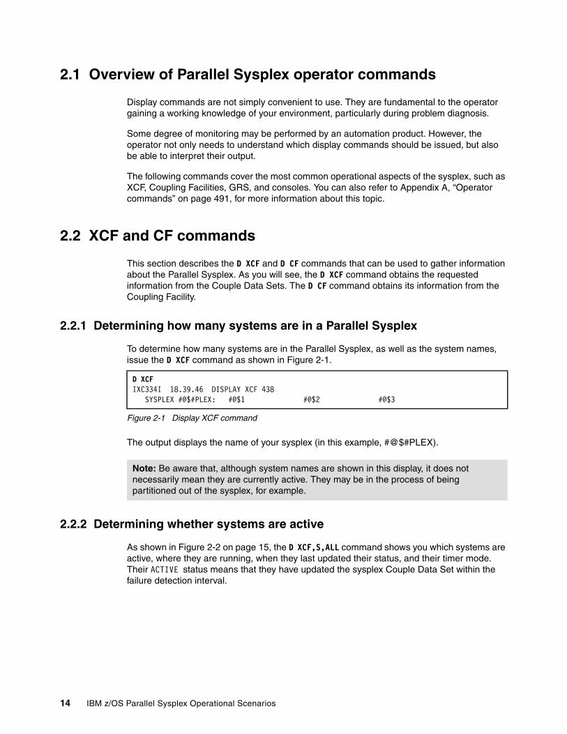
2.1 Overview of Parallel Sysplex operator commands
Display commands are not simply convenient to use. They are fundamental to the operator gaining a working knowledge of your environment, particularly during problem diagnosis.
Some degree of monitoring may be performed by an automation product. However, the operator not only needs to understand which display commands should be issued, but also be able to interpret their output.
The following commands cover the most common operational aspects of the sysplex, such as XCF, Coupling Facilities, GRS, and consoles. You can also refer to Appendix A, “Operator commands” on page 491, for more information about this topic.
2.2 XCF and CF commands
This section describes the D XCF and D CF commands that can be used to gather information about the Parallel Sysplex. As you will see, the D XCF command obtains the requested information from the Couple Data Sets. The D CF command obtains its information from the Coupling Facility.
2.2.1 Determining how many systems are in a Parallel Sysplex
To determine how many systems are in the Parallel Sysplex, as well as the system names, issue the D XCF command as shown in Figure 2-1.
Figure 2-1 Display XCF command
The output displays the name of your sysplex (in this example, #@$#PLEX).
2.2.2 Determining whether systems are active
As shown in Figure 2-2 on page 15, the D XCF,S,ALL command shows you which systems are active, where they are running, when they last updated their status, and their timer mode. Their ACTIVE status means that they have updated the sysplex Couple Data Set within the failure detection interval.
D XCF IXC334I 18.39.46 DISPLAY XCF 438 SYSPLEX #@$#PLEX: #@$1 #@$2 #@$3
Note: Be aware that, although system names are shown in this display, it does not necessarily mean they are currently active. They may be in the process of being partitioned out of the sysplex, for example.
14 IBM z/OS Parallel Sysplex Operational Scenarios
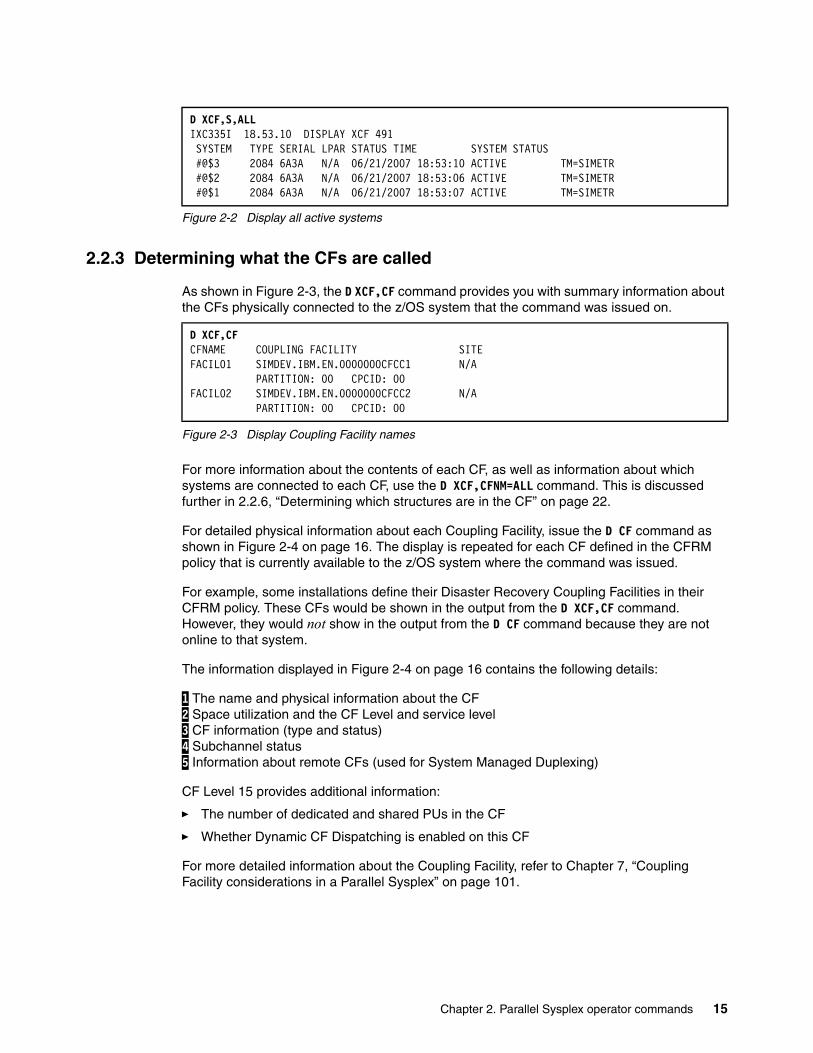
Figure 2-2 Display all active systems
2.2.3 Determining what the CFs are called
As shown in Figure 2-3, the D XCF,CF command provides you with summary information about the CFs physically connected to the z/OS system that the command was issued on.
Figure 2-3 Display Coupling Facility names
For more information about the contents of each CF, as well as information about which systems are connected to each CF, use the D XCF,CFNM=ALL command. This is discussed further in 2.2.6, “Determining which structures are in the CF” on page 22.
For detailed physical information about each Coupling Facility, issue the D CF command as shown in Figure 2-4 on page 16. The display is repeated for each CF defined in the CFRM policy that is currently available to the z/OS system where the command was issued.
For example, some installations define their Disaster Recovery Coupling Facilities in their CFRM policy. These CFs would be shown in the output from the D XCF,CF command. However, they would not show in the output from the D CF command because they are not online to that system.
The information displayed in Figure 2-4 on page 16 contains the following details:
1 The name and physical information about the CF 2 Space utilization and the CF Level and service level 3 CF information (type and status) 4 Subchannel status 5 Information about remote CFs (used for System Managed Duplexing)
CF Level 15 provides additional information:
� The number of dedicated and shared PUs in the CF
� Whether Dynamic CF Dispatching is enabled on this CF
For more detailed information about the Coupling Facility, refer to Chapter 7, “Coupling Facility considerations in a Parallel Sysplex” on page 101.
D XCF,S,ALL IXC335I 18.53.10 DISPLAY XCF 491 SYSTEM TYPE SERIAL LPAR STATUS TIME SYSTEM STATUS #@$3 2084 6A3A N/A 06/21/2007 18:53:10 ACTIVE TM=SIMETR #@$2 2084 6A3A N/A 06/21/2007 18:53:06 ACTIVE TM=SIMETR #@$1 2084 6A3A N/A 06/21/2007 18:53:07 ACTIVE TM=SIMETR
D XCF,CFCFNAME COUPLING FACILITY SITE FACIL01 SIMDEV.IBM.EN.0000000CFCC1 N/A PARTITION: 00 CPCID: 00 FACIL02 SIMDEV.IBM.EN.0000000CFCC2 N/A PARTITION: 00 CPCID: 00
Chapter 2. Parallel Sysplex operator commands 15

Figure 2-4 Display CF details
2.2.4 Obtaining more information about CF paths
When IBM first introduced Coupling Facilities, the links to connect the CF to z/OS were defined as being either CF receiver (CFR) or sender (CFS) paths (type 0B and 0C in the D
D CF IXL150I 19.02.15 DISPLAY CF 516 COUPLING FACILITY SIMDEV.IBM.EN.0000000CFCC1 PARTITION: 00 CPCID: 00 CONTROL UNIT ID: 0309 NAMED FACIL01 1 COUPLING FACILITY SPACE UTILIZATION ALLOCATED SPACE DUMP SPACE UTILIZATION STRUCTURES: 108544 K STRUCTURE DUMP TABLES: 0 K DUMP SPACE: 2048 K TABLE COUNT: 0 FREE SPACE: 612864 K FREE DUMP SPACE: 2048 K TOTAL SPACE: 723456 K TOTAL DUMP SPACE: 2048 K MAX REQUESTED DUMP SPACE: 0 K VOLATILE: YES STORAGE INCREMENT SIZE: 256 K CFLEVEL: 14 CFCC RELEASE 14.00, SERVICE LEVEL 00.29 BUILT ON 03/26/2007 AT 17:58:00 COUPLING FACILITY HAS ONLY SHARED PROCESSORS COUPLING FACILITY SPACE CONFIGURATION 2 IN USE FREE TOTAL CONTROL SPACE: 110592 K 612864 K 723456 K NON-CONTROL SPACE: 0 K 0 K 0 K SENDER PATH 3 PHYSICAL LOGICAL CHANNEL TYPE 09 ONLINE ONLINE ICP
0E ONLINE ONLINE ICP
COUPLING FACILITY SUBCHANNEL STATUS 4 TOTAL: 6 IN USE: 6 NOT USING: 0 NOT USABLE: 0 DEVICE SUBCHANNEL STATUS 4030 0004 OPERATIONAL 4031 0005 OPERATIONAL 4032 0006 OPERATIONAL 4033 0007 OPERATIONAL 4034 0008 OPERATIONAL 4035 0009 OPERATIONAL REMOTELY CONNECTED COUPLING FACILITIES 5 CFNAME COUPLING FACILITY -------- -------------------------- FACIL02 SIMDEV.IBM.EN.0000000CFCC2 PARTITION: 00 CPCID: 00 CHPIDS ON FACIL01 CONNECTED TO REMOTE FACILITY RECEIVER: CHPID TYPE F0 ICP SENDER: CHPID TYPE E0 ICP NOT OPERATIONAL CHPIDS ON FACIL01 81
16 IBM z/OS Parallel Sysplex Operational Scenarios

M=CHP display). When the zSeries range of processors were announced, an enhanced link type (peer mode links) was introduced. Because CFR and CFS links are not strategic, this document only discusses peer mode links.
Previously, on zSeries processors, three types of CF links were supported:
Internal Coupling (IC) This is used to connect a Coupling Facility to a z/OS LPAR in the same processor.
Integrated Cluster Bus (ICB) These are copper links, typically used to connect a Coupling Facility to z/OS in another processor. The processors must be within 7 meters of each other.
Inter-System Coupling (ISC) These are fiber links, with the lowest performance. They can be used to connect z/OS to a Coupling Facility that is up to 100 km away when used with a multiplexor.
System z10™ introduced a new type of CF link known as Parallel Sysplex over Infiniband (PSIFB) or Coupling over Infiniband (CIB). These also use fiber connections, and at the time of writing support a maximum distance of 150 meters between the processors.
There are two ways you can obtain information about the CF links. The first way is to issue a D M=CHP command; Figure 2-5 on page 18 shows an example of the use of this command. Results of the display that are irrelevant to this exercise have been omitted and replaced with an ellipsis (...).
Chapter 2. Parallel Sysplex operator commands 17
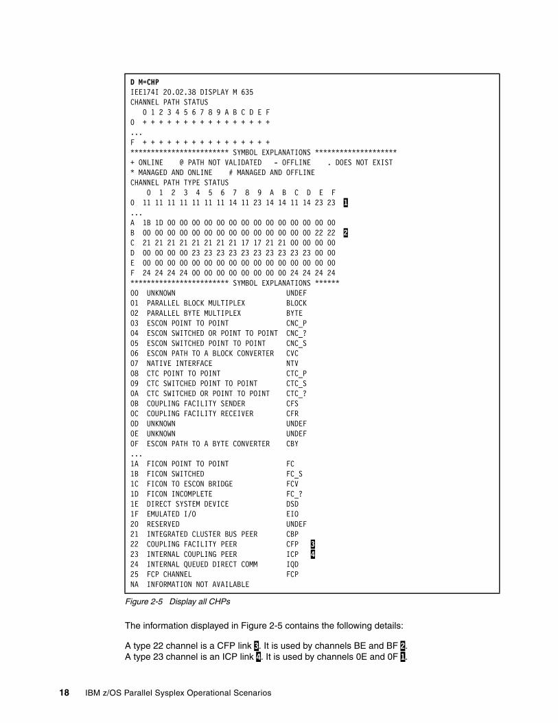
Figure 2-5 Display all CHPs
The information displayed in Figure 2-5 contains the following details:
A type 22 channel is a CFP link 3. It is used by channels BE and BF 2. A type 23 channel is an ICP link 4. It is used by channels 0E and 0F 1.
D M=CHP IEE174I 20.02.38 DISPLAY M 635 CHANNEL PATH STATUS 0 1 2 3 4 5 6 7 8 9 A B C D E F 0 + + + + + + + + + + + + + + + + ...F + + + + + + + + + + + + + + + + ************************ SYMBOL EXPLANATIONS ********************+ ONLINE @ PATH NOT VALIDATED - OFFLINE . DOES NOT EXIST * MANAGED AND ONLINE # MANAGED AND OFFLINE CHANNEL PATH TYPE STATUS 0 1 2 3 4 5 6 7 8 9 A B C D E F 0 11 11 11 11 11 11 11 14 11 23 14 14 11 14 23 23 1 ...A 1B 1D 00 00 00 00 00 00 00 00 00 00 00 00 00 00 B 00 00 00 00 00 00 00 00 00 00 00 00 00 00 22 22 2C 21 21 21 21 21 21 21 21 17 17 21 21 00 00 00 00 D 00 00 00 00 23 23 23 23 23 23 23 23 23 23 00 00 E 00 00 00 00 00 00 00 00 00 00 00 00 00 00 00 00 F 24 24 24 24 00 00 00 00 00 00 00 00 24 24 24 24 ************************ SYMBOL EXPLANATIONS ******00 UNKNOWN UNDEF 01 PARALLEL BLOCK MULTIPLEX BLOCK 02 PARALLEL BYTE MULTIPLEX BYTE 03 ESCON POINT TO POINT CNC_P 04 ESCON SWITCHED OR POINT TO POINT CNC_? 05 ESCON SWITCHED POINT TO POINT CNC_S 06 ESCON PATH TO A BLOCK CONVERTER CVC 07 NATIVE INTERFACE NTV 08 CTC POINT TO POINT CTC_P 09 CTC SWITCHED POINT TO POINT CTC_S 0A CTC SWITCHED OR POINT TO POINT CTC_? 0B COUPLING FACILITY SENDER CFS 0C COUPLING FACILITY RECEIVER CFR 0D UNKNOWN UNDEF 0E UNKNOWN UNDEF 0F ESCON PATH TO A BYTE CONVERTER CBY ...1A FICON POINT TO POINT FC 1B FICON SWITCHED FC_S 1C FICON TO ESCON BRIDGE FCV 1D FICON INCOMPLETE FC_? 1E DIRECT SYSTEM DEVICE DSD 1F EMULATED I/O EIO 20 RESERVED UNDEF 21 INTEGRATED CLUSTER BUS PEER CBP 22 COUPLING FACILITY PEER CFP 323 INTERNAL COUPLING PEER ICP 424 INTERNAL QUEUED DIRECT COMM IQD 25 FCP CHANNEL FCP NA INFORMATION NOT AVAILABLE
18 IBM z/OS Parallel Sysplex Operational Scenarios
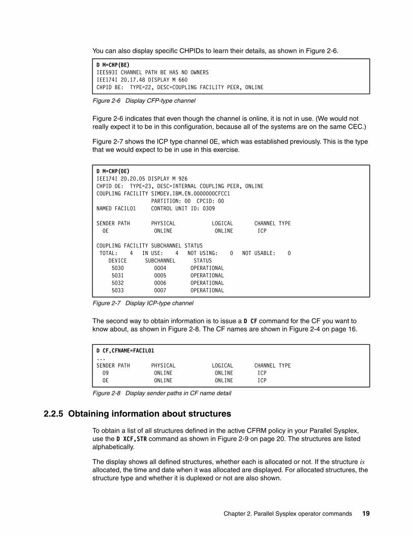
You can also display specific CHPIDs to learn their details, as shown in Figure 2-6.
Figure 2-6 Display CFP-type channel
Figure 2-6 indicates that even though the channel is online, it is not in use. (We would not really expect it to be in this configuration, because all of the systems are on the same CEC.)
Figure 2-7 shows the ICP type channel 0E, which was established previously. This is the type that we would expect to be in use in this exercise.
Figure 2-7 Display ICP-type channel
The second way to obtain information is to issue a D CF command for the CF you want to know about, as shown in Figure 2-8. The CF names are shown in Figure 2-4 on page 16.
Figure 2-8 Display sender paths in CF name detail
2.2.5 Obtaining information about structures
To obtain a list of all structures defined in the active CFRM policy in your Parallel Sysplex, use the D XCF,STR command as shown in Figure 2-9 on page 20. The structures are listed alphabetically.
The display shows all defined structures, whether each is allocated or not. If the structure is allocated, the time and date when it was allocated are displayed. For allocated structures, the structure type and whether it is duplexed or not are also shown.
D M=CHP(BE) IEE593I CHANNEL PATH BE HAS NO OWNERS IEE174I 20.17.48 DISPLAY M 660 CHPID BE: TYPE=22, DESC=COUPLING FACILITY PEER, ONLINE
D M=CHP(0E) IEE174I 20.20.05 DISPLAY M 926 CHPID 0E: TYPE=23, DESC=INTERNAL COUPLING PEER, ONLINE COUPLING FACILITY SIMDEV.IBM.EN.0000000CFCC1 PARTITION: 00 CPCID: 00 NAMED FACIL01 CONTROL UNIT ID: 0309 SENDER PATH PHYSICAL LOGICAL CHANNEL TYPE 0E ONLINE ONLINE ICP COUPLING FACILITY SUBCHANNEL STATUS TOTAL: 4 IN USE: 4 NOT USING: 0 NOT USABLE: 0 DEVICE SUBCHANNEL STATUS 5030 0004 OPERATIONAL 5031 0005 OPERATIONAL 5032 0006 OPERATIONAL 5033 0007 OPERATIONAL
D CF,CFNAME=FACIL01...SENDER PATH PHYSICAL LOGICAL CHANNEL TYPE 09 ONLINE ONLINE ICP 0E ONLINE ONLINE ICP
Chapter 2. Parallel Sysplex operator commands 19
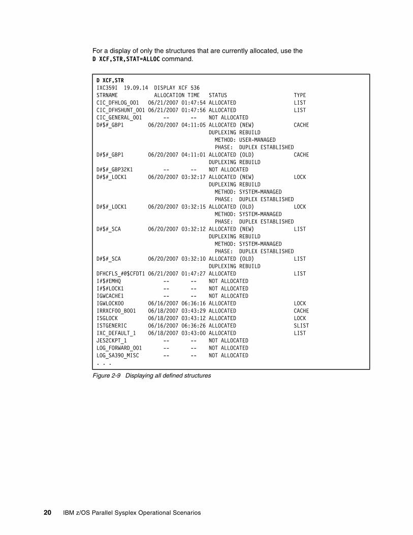
For a display of only the structures that are currently allocated, use the D XCF,STR,STAT=ALLOC command.
Figure 2-9 Displaying all defined structures
D XCF,STR IXC359I 19.09.14 DISPLAY XCF 536 STRNAME ALLOCATION TIME STATUS TYPE CIC_DFHLOG_001 06/21/2007 01:47:54 ALLOCATED LIST CIC_DFHSHUNT_001 06/21/2007 01:47:56 ALLOCATED LIST CIC_GENERAL_001 -- -- NOT ALLOCATED D#$#_GBP1 06/20/2007 04:11:05 ALLOCATED (NEW) CACHE DUPLEXING REBUILD METHOD: USER-MANAGED PHASE: DUPLEX ESTABLISHED D#$#_GBP1 06/20/2007 04:11:01 ALLOCATED (OLD) CACHE DUPLEXING REBUILD D#$#_GBP32K1 -- -- NOT ALLOCATED D#$#_LOCK1 06/20/2007 03:32:17 ALLOCATED (NEW) LOCK DUPLEXING REBUILD METHOD: SYSTEM-MANAGED PHASE: DUPLEX ESTABLISHED D#$#_LOCK1 06/20/2007 03:32:15 ALLOCATED (OLD) LOCK METHOD: SYSTEM-MANAGED PHASE: DUPLEX ESTABLISHED D#$#_SCA 06/20/2007 03:32:12 ALLOCATED (NEW) LIST DUPLEXING REBUILD METHOD: SYSTEM-MANAGED PHASE: DUPLEX ESTABLISHED D#$#_SCA 06/20/2007 03:32:10 ALLOCATED (OLD) LIST DUPLEXING REBUILD DFHCFLS_#@$CFDT1 06/21/2007 01:47:27 ALLOCATED LIST I#$#EMHQ -- -- NOT ALLOCATED I#$#LOCK1 -- -- NOT ALLOCATED IGWCACHE1 -- -- NOT ALLOCATED IGWLOCK00 06/16/2007 06:36:16 ALLOCATED LOCK IRRXCF00_B001 06/18/2007 03:43:29 ALLOCATED CACHE ISGLOCK 06/18/2007 03:43:12 ALLOCATED LOCK ISTGENERIC 06/16/2007 06:36:26 ALLOCATED SLIST IXC_DEFAULT_1 06/18/2007 03:43:00 ALLOCATED LIST JES2CKPT_1 -- -- NOT ALLOCATED LOG_FORWARD_001 -- -- NOT ALLOCATED LOG_SA390_MISC -- -- NOT ALLOCATED . . .
20 IBM z/OS Parallel Sysplex Operational Scenarios
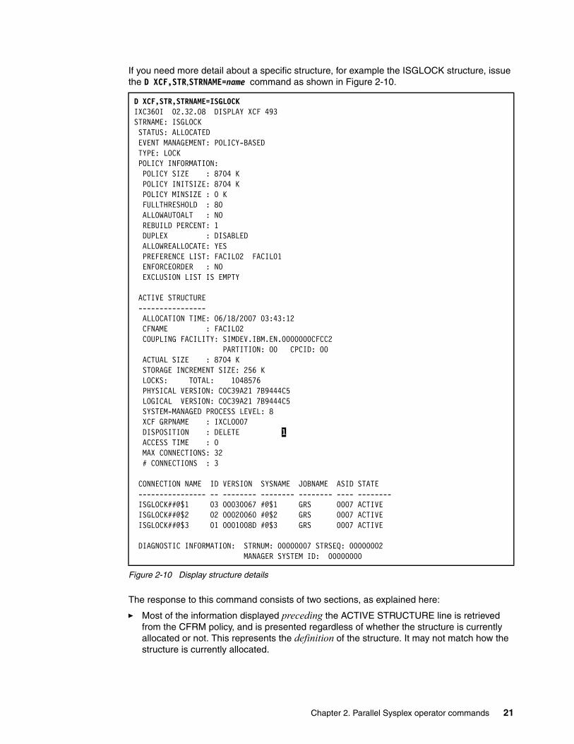
If you need more detail about a specific structure, for example the ISGLOCK structure, issue the D XCF,STR,STRNAME=name command as shown in Figure 2-10.
Figure 2-10 Display structure details
The response to this command consists of two sections, as explained here:
� Most of the information displayed preceding the ACTIVE STRUCTURE line is retrieved from the CFRM policy, and is presented regardless of whether the structure is currently allocated or not. This represents the definition of the structure. It may not match how the structure is currently allocated.
D XCF,STR,STRNAME=ISGLOCK IXC360I 02.32.08 DISPLAY XCF 493 STRNAME: ISGLOCK STATUS: ALLOCATED EVENT MANAGEMENT: POLICY-BASED TYPE: LOCK POLICY INFORMATION: POLICY SIZE : 8704 K POLICY INITSIZE: 8704 K POLICY MINSIZE : 0 K FULLTHRESHOLD : 80 ALLOWAUTOALT : NO REBUILD PERCENT: 1 DUPLEX : DISABLED ALLOWREALLOCATE: YES PREFERENCE LIST: FACIL02 FACIL01 ENFORCEORDER : NO EXCLUSION LIST IS EMPTY ACTIVE STRUCTURE ---------------- ALLOCATION TIME: 06/18/2007 03:43:12 CFNAME : FACIL02 COUPLING FACILITY: SIMDEV.IBM.EN.0000000CFCC2 PARTITION: 00 CPCID: 00 ACTUAL SIZE : 8704 K STORAGE INCREMENT SIZE: 256 K LOCKS: TOTAL: 1048576 PHYSICAL VERSION: C0C39A21 7B9444C5 LOGICAL VERSION: C0C39A21 7B9444C5 SYSTEM-MANAGED PROCESS LEVEL: 8 XCF GRPNAME : IXCLO007 DISPOSITION : DELETE 1 ACCESS TIME : 0 MAX CONNECTIONS: 32 # CONNECTIONS : 3 CONNECTION NAME ID VERSION SYSNAME JOBNAME ASID STATE ---------------- -- -------- -------- -------- ---- -------- ISGLOCK##@$1 03 00030067 #@$1 GRS 0007 ACTIVE ISGLOCK##@$2 02 00020060 #@$2 GRS 0007 ACTIVE ISGLOCK##@$3 01 0001008D #@$3 GRS 0007 ACTIVE DIAGNOSTIC INFORMATION: STRNUM: 00000007 STRSEQ: 00000002 MANAGER SYSTEM ID: 00000000
Chapter 2. Parallel Sysplex operator commands 21
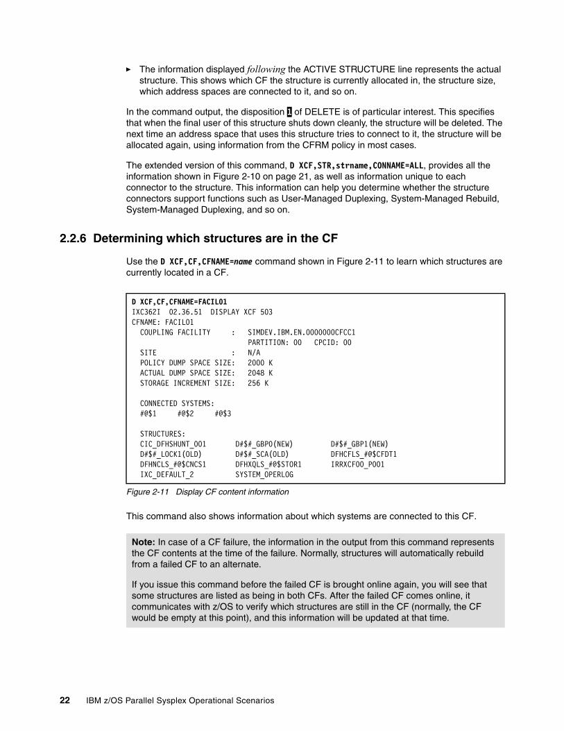
� The information displayed following the ACTIVE STRUCTURE line represents the actual structure. This shows which CF the structure is currently allocated in, the structure size, which address spaces are connected to it, and so on.
In the command output, the disposition 1 of DELETE is of particular interest. This specifies that when the final user of this structure shuts down cleanly, the structure will be deleted. The next time an address space that uses this structure tries to connect to it, the structure will be allocated again, using information from the CFRM policy in most cases.
The extended version of this command, D XCF,STR,strname,CONNAME=ALL, provides all the information shown in Figure 2-10 on page 21, as well as information unique to each connector to the structure. This information can help you determine whether the structure connectors support functions such as User-Managed Duplexing, System-Managed Rebuild, System-Managed Duplexing, and so on.
2.2.6 Determining which structures are in the CF
Use the D XCF,CF,CFNAME=name command shown in Figure 2-11 to learn which structures are currently located in a CF.
Figure 2-11 Display CF content information
This command also shows information about which systems are connected to this CF.
D XCF,CF,CFNAME=FACIL01 IXC362I 02.36.51 DISPLAY XCF 503 CFNAME: FACIL01 COUPLING FACILITY : SIMDEV.IBM.EN.0000000CFCC1 PARTITION: 00 CPCID: 00 SITE : N/A POLICY DUMP SPACE SIZE: 2000 K ACTUAL DUMP SPACE SIZE: 2048 K STORAGE INCREMENT SIZE: 256 K CONNECTED SYSTEMS: #@$1 #@$2 #@$3 STRUCTURES: CIC_DFHSHUNT_001 D#$#_GBP0(NEW) D#$#_GBP1(NEW) D#$#_LOCK1(OLD) D#$#_SCA(OLD) DFHCFLS_#@$CFDT1 DFHNCLS_#@$CNCS1 DFHXQLS_#@$STOR1 IRRXCF00_P001 IXC_DEFAULT_2 SYSTEM_OPERLOG
Note: In case of a CF failure, the information in the output from this command represents the CF contents at the time of the failure. Normally, structures will automatically rebuild from a failed CF to an alternate.
If you issue this command before the failed CF is brought online again, you will see that some structures are listed as being in both CFs. After the failed CF comes online, it communicates with z/OS to verify which structures are still in the CF (normally, the CF would be empty at this point), and this information will be updated at that time.
22 IBM z/OS Parallel Sysplex Operational Scenarios
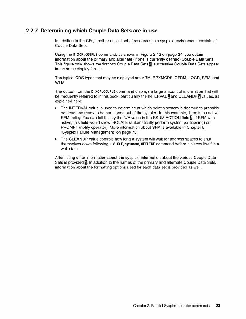
2.2.7 Determining which Couple Data Sets are in use
In addition to the CFs, another critical set of resources in a sysplex environment consists of Couple Data Sets.
Using the D XCF,COUPLE command, as shown in Figure 2-12 on page 24, you obtain information about the primary and alternate (if one is currently defined) Couple Data Sets. This figure only shows the first two Couple Data Sets 4; successive Couple Data Sets appear in the same display format.
The typical CDS types that may be displayed are ARM, BPXMCDS, CFRM, LOGR, SFM, and WLM.
The output from the D XCF,COUPLE command displays a large amount of information that will be frequently referred to in this book, particularly the INTERVAL 1 and CLEANUP 2 values, as explained here:
� The INTERVAL value is used to determine at which point a system is deemed to probably be dead and ready to be partitioned out of the sysplex. In this example, there is no active SFM policy. You can tell this by the N/A value in the SSUM ACTION field 3. If SFM was active, this field would show ISOLATE (automatically perform system partitioning) or PROMPT (notify operator). More information about SFM is available in Chapter 5, “Sysplex Failure Management” on page 73.
� The CLEANUP value controls how long a system will wait for address spaces to shut themselves down following a V XCF,sysname,OFFLINE command before it places itself in a wait state.
After listing other information about the sysplex, information about the various Couple Data Sets is provided 4. In addition to the names of the primary and alternate Couple Data Sets, information about the formatting options used for each data set is provided as well.
Chapter 2. Parallel Sysplex operator commands 23
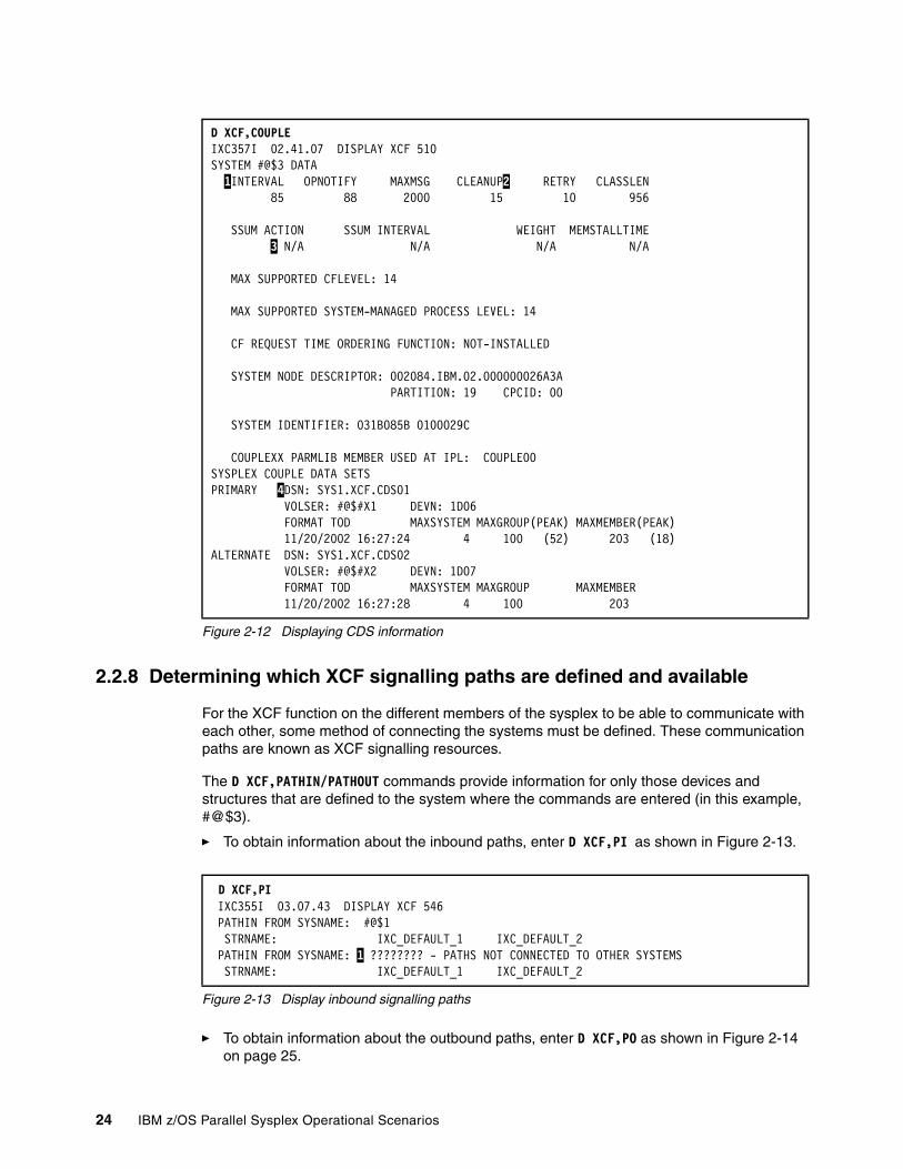
Figure 2-12 Displaying CDS information
2.2.8 Determining which XCF signalling paths are defined and available
For the XCF function on the different members of the sysplex to be able to communicate with each other, some method of connecting the systems must be defined. These communication paths are known as XCF signalling resources.
The D XCF,PATHIN/PATHOUT commands provide information for only those devices and structures that are defined to the system where the commands are entered (in this example, #@$3).
� To obtain information about the inbound paths, enter D XCF,PI as shown in Figure 2-13.
Figure 2-13 Display inbound signalling paths
� To obtain information about the outbound paths, enter D XCF,PO as shown in Figure 2-14 on page 25.
D XCF,COUPLE IXC357I 02.41.07 DISPLAY XCF 510 SYSTEM #@$3 DATA 1INTERVAL OPNOTIFY MAXMSG CLEANUP2 RETRY CLASSLEN 85 88 2000 15 10 956 SSUM ACTION SSUM INTERVAL WEIGHT MEMSTALLTIME 3 N/A N/A N/A N/A MAX SUPPORTED CFLEVEL: 14 MAX SUPPORTED SYSTEM-MANAGED PROCESS LEVEL: 14 CF REQUEST TIME ORDERING FUNCTION: NOT-INSTALLED SYSTEM NODE DESCRIPTOR: 002084.IBM.02.000000026A3A PARTITION: 19 CPCID: 00 SYSTEM IDENTIFIER: 031B085B 0100029C COUPLEXX PARMLIB MEMBER USED AT IPL: COUPLE00 SYSPLEX COUPLE DATA SETS PRIMARY 4DSN: SYS1.XCF.CDS01 VOLSER: #@$#X1 DEVN: 1D06 FORMAT TOD MAXSYSTEM MAXGROUP(PEAK) MAXMEMBER(PEAK) 11/20/2002 16:27:24 4 100 (52) 203 (18)ALTERNATE DSN: SYS1.XCF.CDS02 VOLSER: #@$#X2 DEVN: 1D07 FORMAT TOD MAXSYSTEM MAXGROUP MAXMEMBER 11/20/2002 16:27:28 4 100 203
D XCF,PI IXC355I 03.07.43 DISPLAY XCF 546 PATHIN FROM SYSNAME: #@$1 STRNAME: IXC_DEFAULT_1 IXC_DEFAULT_2 PATHIN FROM SYSNAME: 1 ???????? - PATHS NOT CONNECTED TO OTHER SYSTEMS STRNAME: IXC_DEFAULT_1 IXC_DEFAULT_2
24 IBM z/OS Parallel Sysplex Operational Scenarios
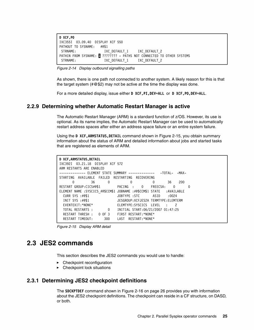
Figure 2-14 Display outbound signalling paths
As shown, there is one path not connected to another system. A likely reason for this is that the target system (#@$2) may not be active at the time the display was done.
For a more detailed display, issue either D XCF,PI,DEV=ALL or D XCF,PO,DEV=ALL.
2.2.9 Determining whether Automatic Restart Manager is active
The Automatic Restart Manager (ARM) is a standard function of z/OS. However, its use is optional. As its name implies, the Automatic Restart Manager can be used to automatically restart address spaces after either an address space failure or an entire system failure.
Using the D XCF,ARMSTATUS,DETAIL command shown in Figure 2-15, you obtain summary information about the status of ARM and detailed information about jobs and started tasks that are registered as elements of ARM.
Figure 2-15 Display ARM detail
2.3 JES2 commands
This section describes the JES2 commands you would use to handle:
� Checkpoint reconfiguration� Checkpoint lock situations
2.3.1 Determining JES2 checkpoint definitions
The $DCKPTDEF command shown in Figure 2-16 on page 26 provides you with information about the JES2 checkpoint definitions. The checkpoint can reside in a CF structure, on DASD, or both.
D XCF,PO IXC355I 03.09.40 DISPLAY XCF 550 PATHOUT TO SYSNAME: #@$1 STRNAME: IXC_DEFAULT_1 IXC_DEFAULT_2PATHIN FROM SYSNAME: 1 ???????? - PATHS NOT CONNECTED TO OTHER SYSTEMS STRNAME: IXC_DEFAULT_1 IXC_DEFAULT_2
D XCF,ARMSTATUS,DETAIL IXC392I 03.21.18 DISPLAY XCF 572 ARM RESTARTS ARE ENABLED -------------- ELEMENT STATE SUMMARY -------------- -TOTAL- -MAX- STARTING AVAILABLE FAILED RESTARTING RECOVERING 0 36 0 0 0 36 200 RESTART GROUP:CICS#@$1 PACING : 0 FREECSA: 0 0ELEMENT NAME :SYSCICS_#@$CCM$1 JOBNAME :#@$CCM$1 STATE :AVAILABLE CURR SYS :#@$1 JOBTYPE :STC ASID :0024 INIT SYS :#@$1 JESGROUP:XCFJES2A TERMTYPE:ELEMTERM EVENTEXIT:*NONE* ELEMTYPE:SYSCICS LEVEL : 2 TOTAL RESTARTS : 0 INITIAL START:06/21/2007 01:47:25 RESTART THRESH : 0 OF 3 FIRST RESTART:*NONE* RESTART TIMEOUT: 300 LAST RESTART:*NONE*
Chapter 2. Parallel Sysplex operator commands 25
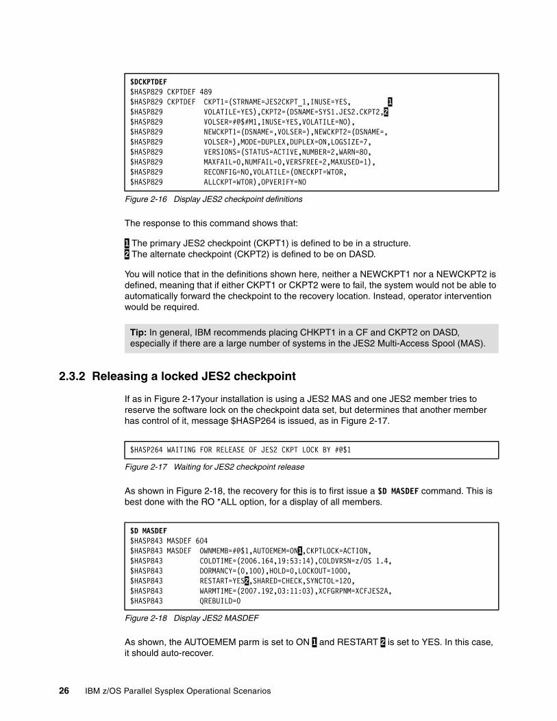
Figure 2-16 Display JES2 checkpoint definitions
The response to this command shows that:
1 The primary JES2 checkpoint (CKPT1) is defined to be in a structure. 2 The alternate checkpoint (CKPT2) is defined to be on DASD.
You will notice that in the definitions shown here, neither a NEWCKPT1 nor a NEWCKPT2 is defined, meaning that if either CKPT1 or CKPT2 were to fail, the system would not be able to automatically forward the checkpoint to the recovery location. Instead, operator intervention would be required.
2.3.2 Releasing a locked JES2 checkpoint
If as in Figure 2-17your installation is using a JES2 MAS and one JES2 member tries to reserve the software lock on the checkpoint data set, but determines that another member has control of it, message $HASP264 is issued, as in Figure 2-17.
Figure 2-17 Waiting for JES2 checkpoint release
As shown in Figure 2-18, the recovery for this is to first issue a $D MASDEF command. This is best done with the RO *ALL option, for a display of all members.
Figure 2-18 Display JES2 MASDEF
As shown, the AUTOEMEM parm is set to ON 1 and RESTART 2 is set to YES. In this case, it should auto-recover.
$DCKPTDEF $HASP829 CKPTDEF 489 $HASP829 CKPTDEF CKPT1=(STRNAME=JES2CKPT_1,INUSE=YES, 1 $HASP829 VOLATILE=YES),CKPT2=(DSNAME=SYS1.JES2.CKPT2,2 $HASP829 VOLSER=#@$#M1,INUSE=YES,VOLATILE=NO), $HASP829 NEWCKPT1=(DSNAME=,VOLSER=),NEWCKPT2=(DSNAME=, $HASP829 VOLSER=),MODE=DUPLEX,DUPLEX=ON,LOGSIZE=7, $HASP829 VERSIONS=(STATUS=ACTIVE,NUMBER=2,WARN=80, $HASP829 MAXFAIL=0,NUMFAIL=0,VERSFREE=2,MAXUSED=1), $HASP829 RECONFIG=NO,VOLATILE=(ONECKPT=WTOR, $HASP829 ALLCKPT=WTOR),OPVERIFY=NO
Tip: In general, IBM recommends placing CHKPT1 in a CF and CKPT2 on DASD, especially if there are a large number of systems in the JES2 Multi-Access Spool (MAS).
$HASP264 WAITING FOR RELEASE OF JES2 CKPT LOCK BY #@$1
$D MASDEF $HASP843 MASDEF 604 $HASP843 MASDEF OWNMEMB=#@$1,AUTOEMEM=ON1,CKPTLOCK=ACTION, $HASP843 COLDTIME=(2006.164,19:53:14),COLDVRSN=z/OS 1.4,$HASP843 DORMANCY=(0,100),HOLD=0,LOCKOUT=1000, $HASP843 RESTART=YES2,SHARED=CHECK,SYNCTOL=120, $HASP843 WARMTIME=(2007.192,03:11:03),XCFGRPNM=XCFJES2A,$HASP843 QREBUILD=0
26 IBM z/OS Parallel Sysplex Operational Scenarios
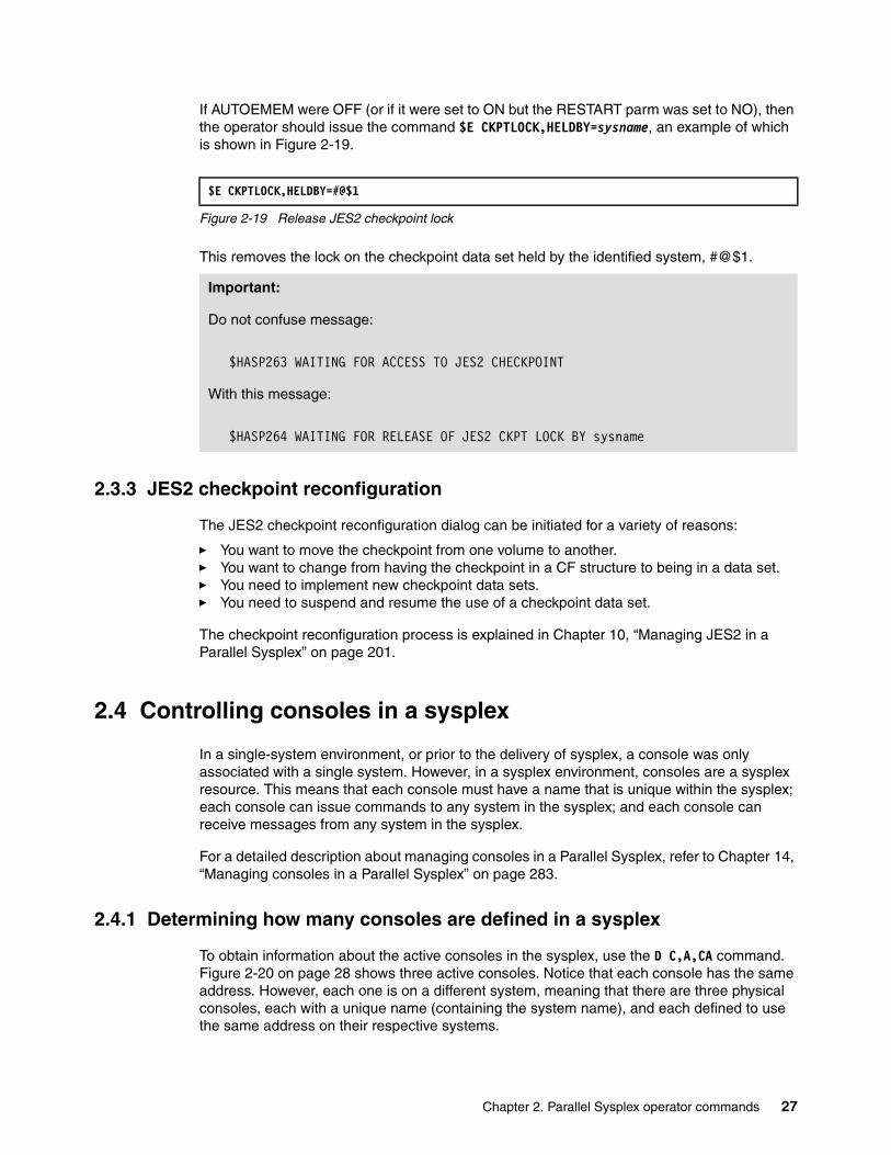
If AUTOEMEM were OFF (or if it were set to ON but the RESTART parm was set to NO), then the operator should issue the command $E CKPTLOCK,HELDBY=sysname, an example of which is shown in Figure 2-19.
Figure 2-19 Release JES2 checkpoint lock
This removes the lock on the checkpoint data set held by the identified system, #@$1.
2.3.3 JES2 checkpoint reconfiguration
The JES2 checkpoint reconfiguration dialog can be initiated for a variety of reasons:
� You want to move the checkpoint from one volume to another.� You want to change from having the checkpoint in a CF structure to being in a data set.� You need to implement new checkpoint data sets.� You need to suspend and resume the use of a checkpoint data set.
The checkpoint reconfiguration process is explained in Chapter 10, “Managing JES2 in a Parallel Sysplex” on page 201.
2.4 Controlling consoles in a sysplex
In a single-system environment, or prior to the delivery of sysplex, a console was only associated with a single system. However, in a sysplex environment, consoles are a sysplex resource. This means that each console must have a name that is unique within the sysplex; each console can issue commands to any system in the sysplex; and each console can receive messages from any system in the sysplex.
For a detailed description about managing consoles in a Parallel Sysplex, refer to Chapter 14, “Managing consoles in a Parallel Sysplex” on page 283.
2.4.1 Determining how many consoles are defined in a sysplex
To obtain information about the active consoles in the sysplex, use the D C,A,CA command. Figure 2-20 on page 28 shows three active consoles. Notice that each console has the same address. However, each one is on a different system, meaning that there are three physical consoles, each with a unique name (containing the system name), and each defined to use the same address on their respective systems.
$E CKPTLOCK,HELDBY=#@$1
Important:
Do not confuse message:
$HASP263 WAITING FOR ACCESS TO JES2 CHECKPOINT
With this message:
$HASP264 WAITING FOR RELEASE OF JES2 CKPT LOCK BY sysname
Chapter 2. Parallel Sysplex operator commands 27

Figure 2-20 Display active consoles
2.4.2 Managing console messages
z/OS provides great flexibility regarding which messages will appear on each console. In general, the decision about which subset of messages a given console will see is determined by the responsibilities of the group that uses that console. For example, the console in the tape drive area might be set up to see all tape mount requests from all systems in the sysplex.
Explaining how to plan and set up your console configuration is beyond the scope of this book. Here, we simply highlight some of the commands you can use to control the scope of which systems can send messages to a particular console.
To receive only messages from the image that the console is defined on, use the V CN(*),MSCOPE=(*) command. To receive messages from all systems in your sysplex, use the V CN(*),MSCOPE=*ALL command. Note, however, that setting a console up in this manner is not recommended due to possible console flooding. However, when used with the ROUTCDE parm to reduce the potential number of messages being routed to the console, it may be acceptable. You may also use the V CN(*),MSCOPE=(sys1,sys2,....) format to receive messages from more than one, but less than all the systems in the sysplex.
2.5 GRS commands
This section describes the GRS commands you can use to get information about your Global Resource Serialization (GRS) Star complex. The old Ring configuration is not addressed in this book. This is because all Parallel Sysplex members must be in the same GRS complex, and it is recommended that you use GRS Star for both improved performance and availability. Note that you cannot have a GRS complex containing a mix of systems in the sysplex and systems outside the sysplex when using GRS Star.
2.5.1 Determining which systems are in a GRS complex
For summary information about your GRS complex, use the D GRS command shown in Figure 2-21 on page 29.
D C,A,CA IEE890I 03.54.03 CONSOLE DISPLAY 830 NAME ID SYSTEM ADDRESS STATUS #@$1M01 13 #@$1 08E0 ACTIVE #@$2M01 11 #@$2 08E0 ACTIVE #@$3M01 01 #@$3 08E0 ACTIVE
Note: Starting with z/OS 1.8, it is no longer necessary (or possible) to have a single sysplex Master console, although you can still have multiple consoles that have master authority.
28 IBM z/OS Parallel Sysplex Operational Scenarios
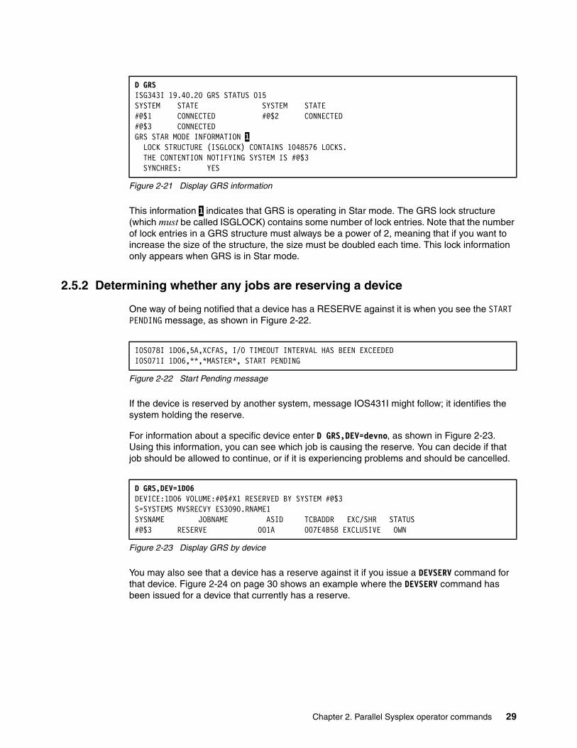
Figure 2-21 Display GRS information
This information 1 indicates that GRS is operating in Star mode. The GRS lock structure (which must be called ISGLOCK) contains some number of lock entries. Note that the number of lock entries in a GRS structure must always be a power of 2, meaning that if you want to increase the size of the structure, the size must be doubled each time. This lock information only appears when GRS is in Star mode.
2.5.2 Determining whether any jobs are reserving a device
One way of being notified that a device has a RESERVE against it is when you see the START PENDING message, as shown in Figure 2-22.
Figure 2-22 Start Pending message
If the device is reserved by another system, message IOS431I might follow; it identifies the system holding the reserve.
For information about a specific device enter D GRS,DEV=devno, as shown in Figure 2-23. Using this information, you can see which job is causing the reserve. You can decide if that job should be allowed to continue, or if it is experiencing problems and should be cancelled.
Figure 2-23 Display GRS by device
You may also see that a device has a reserve against it if you issue a DEVSERV command for that device. Figure 2-24 on page 30 shows an example where the DEVSERV command has been issued for a device that currently has a reserve.
D GRS ISG343I 19.40.20 GRS STATUS 015 SYSTEM STATE SYSTEM STATE #@$1 CONNECTED #@$2 CONNECTED #@$3 CONNECTED GRS STAR MODE INFORMATION 1 LOCK STRUCTURE (ISGLOCK) CONTAINS 1048576 LOCKS. THE CONTENTION NOTIFYING SYSTEM IS #@$3 SYNCHRES: YES
IOS078I 1D06,5A,XCFAS, I/O TIMEOUT INTERVAL HAS BEEN EXCEEDEDIOS071I 1D06,**,*MASTER*, START PENDING
D GRS,DEV=1D06DEVICE:1D06 VOLUME:#@$#X1 RESERVED BY SYSTEM #@$3 S=SYSTEMS MVSRECVY ES3090.RNAME1 SYSNAME JOBNAME ASID TCBADDR EXC/SHR STATUS #@$3 RESERVE 001A 007E4B58 EXCLUSIVE OWN
Chapter 2. Parallel Sysplex operator commands 29

Figure 2-24 Devserv on paths of reserved device
The reserve also shows up with the D U command shown in Figure 2-25.
Figure 2-25 D U of a reserved device
Even if a device has a reserve against it, that is not necessarily a problem. Be aware, however, that no other system will be able to update a data set on a volume that has a reserve against it, so reserves that impact another job for a long time should be investigated.
2.5.3 Determining whether there is resource contention in a sysplex
Another way that a program can serialize a resource is by issuing an ENQ request. This is considered preferable to using a reserve, because only the ENQed resource is serialized, rather than the whole volume.
However, there is still the possibility than a program can hold an ENQ for a long time, locking out other programs that may want to use that resource. If you find that a program is stopped, you can use the D GRS,C command to determine if that program is being delayed because of ENQ or Latch contention, as shown in Figure 2-26.
Figure 2-26 Display GRS contention
2.5.4 Obtaining contention information about a specific data set
You can use the D GRS,RES=(*,dsn) command to obtain information about a specific data set, as shown in Figure 2-27 on page 31. The output is similar to that provided by the D GRS,C command.
DS P,1D00 IEE459I 20.23.09 DEVSERV PATHS 060 UNIT DTYPE M CNT VOLSER CHPID=PATH STATUS RTYPE SSID CFW TC DFW PIN DC-STATE CCA DDC ALT1D00,33903 ,A,023,#@$#M1,5A=R 5B=R 5C=R 5D=R 2105 8981 Y YY. YY. N SIMPLEX 32 32 ************************ SYMBOL DEFINITIONS *****************A = ALLOCATED R = PATH AVAILABLE AND RES
D U,,,1D00,1 IEE457I 20.21.59 UNIT STATUS 047 UNIT TYPE STATUS VOLSER VOLSTATE 1D00 3390 A -R #@$#M1 PRIV/RSDNT
D GRS,C ISG343I 00.10.35 GRS STATUS 324 S=SYSTEMS SYSDSN EXAMPLE1.XX SYSNAME JOBNAME ASID TCBADDR EXC/SHR STATUS#@$3 SAMPJOB1 001A 007FF290 EXCLUSIVE OWN #@$3 SAMPJOB2 001F 007FF290 SHARE WAIT NO REQUESTS PENDING FOR ISGLOCK STRUCTURE NO LATCH CONTENTION EXISTS
30 IBM z/OS Parallel Sysplex Operational Scenarios
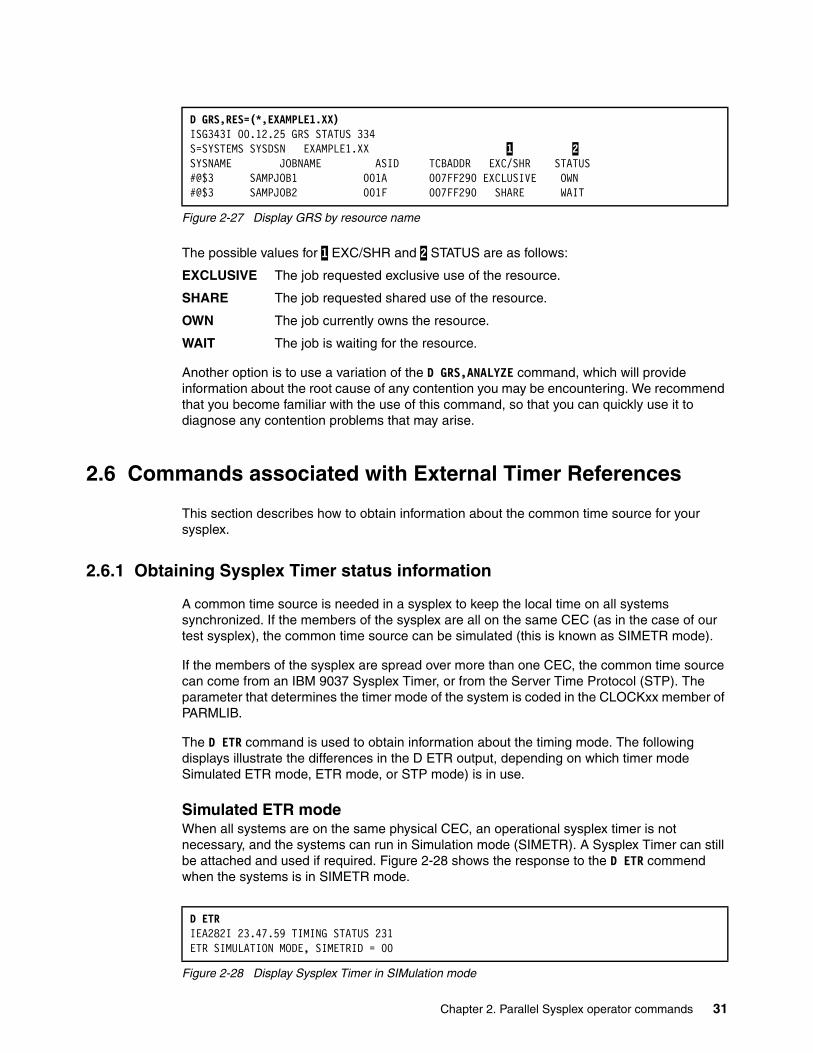
Figure 2-27 Display GRS by resource name
The possible values for 1 EXC/SHR and 2 STATUS are as follows:
EXCLUSIVE The job requested exclusive use of the resource.
SHARE The job requested shared use of the resource.
OWN The job currently owns the resource.
WAIT The job is waiting for the resource.
Another option is to use a variation of the D GRS,ANALYZE command, which will provide information about the root cause of any contention you may be encountering. We recommend that you become familiar with the use of this command, so that you can quickly use it to diagnose any contention problems that may arise.
2.6 Commands associated with External Timer References
This section describes how to obtain information about the common time source for your sysplex.
2.6.1 Obtaining Sysplex Timer status information
A common time source is needed in a sysplex to keep the local time on all systems synchronized. If the members of the sysplex are all on the same CEC (as in the case of our test sysplex), the common time source can be simulated (this is known as SIMETR mode).
If the members of the sysplex are spread over more than one CEC, the common time source can come from an IBM 9037 Sysplex Timer, or from the Server Time Protocol (STP). The parameter that determines the timer mode of the system is coded in the CLOCKxx member of PARMLIB.
The D ETR command is used to obtain information about the timing mode. The following displays illustrate the differences in the D ETR output, depending on which timer mode Simulated ETR mode, ETR mode, or STP mode) is in use.
Simulated ETR modeWhen all systems are on the same physical CEC, an operational sysplex timer is not necessary, and the systems can run in Simulation mode (SIMETR). A Sysplex Timer can still be attached and used if required. Figure 2-28 shows the response to the D ETR commend when the systems is in SIMETR mode.
Figure 2-28 Display Sysplex Timer in SIMulation mode
D GRS,RES=(*,EXAMPLE1.XX) ISG343I 00.12.25 GRS STATUS 334 S=SYSTEMS SYSDSN EXAMPLE1.XX 1 2 SYSNAME JOBNAME ASID TCBADDR EXC/SHR STATUS #@$3 SAMPJOB1 001A 007FF290 EXCLUSIVE OWN #@$3 SAMPJOB2 001F 007FF290 SHARE WAIT
D ETR IEA282I 23.47.59 TIMING STATUS 231 ETR SIMULATION MODE, SIMETRID = 00
Chapter 2. Parallel Sysplex operator commands 31

ETR mode The 9037s provide the setting and synchronization for the TOD clocks of the CEC or multiple CECs. The IPLing system determines the timing mode from the CEC. Each CEC should be connected to two 9037s, thus providing the ability to continue operating even if one 9037 fails.
Figure 2-29 shows the status of the two ETR ports on the CEC. In this display, the ETR NET ID of both 9037s is the same; only the port numbers and ETR ID differ. The display shows which 9037 is currently being used for the time synchronization signals. If that 9037 or the connection to it were to fail, the CEC will automatically switch to the backup.
Figure 2-29 Display Sysplex Timer ETR
STP modeServer Time Protocol is the logical replacement for 9037s. STP is a message-based protocol in which timekeeping information is passed over data links between CECs.
STP must run a Coordinated Timing Network (CTN). Like the 9037, the same network ID must be used by all systems that are to have synchronized times.
This network can be configured as STP-only, where all CECs use only STP, or the network can be configured as Mixed. A Mixed network uses both STP and 9037s. In a Mixed CTN, the 9037 still controls the time for the whole sysplex.
Figure 2-30 shows the response from a system in STP mode.
Figure 2-30 Display Sysplex Timer with STP
Using D XCF,S,AllAnother way to see the timing mode of each system in the sysplex is to issue the D XCF,S,ALL command. This will show TM=ETR, TM=SIMETR, or TM=STP.
For more information about STP, refer to Server Time Protocol Planning Guide, SG24-7280.
2.7 Miscellaneous commands and displays
This section describes additional commands that are useful in managing a Parallel Sysplex.
D ETR IEA282I 23.38.48 TIMING STATUS 550 SYNCHRONIZATION MODE = ETR CPC PORT 0 <== ACTIVE CPC PORT 1 OPERATIONAL OPERATIONAL ENABLED ENABLED ETR NET ID=01 ETR NET ID=01 ETR PORT=01 ETR PORT=02 ETR ID=00 ETR ID=01
D ETRSYNCHRONIZATION MODE = STP THIS SERVER IS A STRATUM 1 CTN ID = ISCTEST THE STRATUM 1 NODE ID = 002084.C24.IBM.02.000000046875 THIS IS THE PREFERRED TIME SERVER THIS STP NETWORK HAS NO SERVER TO ACT AS ARBITER
32 IBM z/OS Parallel Sysplex Operational Scenarios
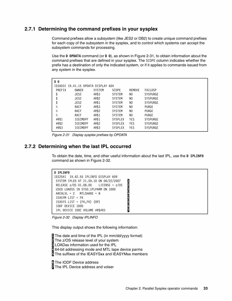
2.7.1 Determining the command prefixes in your sysplex
Command prefixes allow a subsystem (like JES2 or DB2) to create unique command prefixes for each copy of the subsystem in the sysplex, and to control which systems can accept the subsystem commands for processing.
Use the D OPDATA command (or D O), as shown in Figure 2-31, to obtain information about the command prefixes that are defined in your sysplex. The SCOPE column indicates whether the prefix has a destination of only the indicated system, or if it applies to commands issued from any system in the sysplex.
Figure 2-31 Display sysplex prefixes by OPDATA
2.7.2 Determining when the last IPL occurred
To obtain the date, time, and other useful information about the last IPL, use the D IPLINFO command as shown in Figure 2-32.
Figure 2-32 Display IPLINFO
This display output shows the following information:
1 The date and time of the IPL (in mm/dd/yyyy format) 2 The z/OS release level of your system 3 LOADxx information used for the IPL 4 64-bit addressing mode and MTL tape device parms 5 The suffixes of the IEASYSxx and IEASYMxx members
6 The IODF Device address 7 The IPL Device address and volser
D O IEE603I 19.41.15 OPDATA DISPLAY 604 PREFIX OWNER SYSTEM SCOPE REMOVE FAILDSP $ JES2 #@$3 SYSTEM NO SYSPURGE $ JES2 #@$2 SYSTEM NO SYSPURGE $ JES2 #@$1 SYSTEM NO SYSPURGE % RACF #@$3 SYSTEM NO PURGE % RACF #@$2 SYSTEM NO PURGE % RACF #@$1 SYSTEM NO PURGE #@$1 IEECMDPF #@$1 SYSPLEX YES SYSPURGE #@$2 IEECMDPF #@$2 SYSPLEX YES SYSPURGE #@$3 IEECMDPF #@$3 SYSPLEX YES SYSPURGE
D IPLINFO IEE254I 19.42.55 IPLINFO DISPLAY 609 SYSTEM IPLED AT 21.59.10 ON 06/22/2007 1 RELEASE z/OS 01.08.00 LICENSE = z/OS 2 USED LOADSS IN SYS0.IPLPARM ON 1D00 3 ARCHLVL = 2 MTLSHARE = N 4 IEASYM LIST = FK 5 IEASYS LIST = (FK,FK) (OP) 5 IODF DEVICE 1D00 6 IPL DEVICE 1D0C VOLUME #@$#R3 7
Chapter 2. Parallel Sysplex operator commands 33
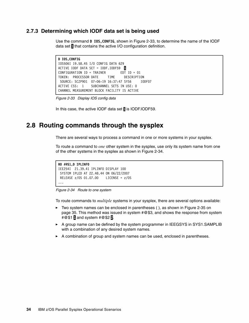
2.7.3 Determining which IODF data set is being used
Use the command D IOS,CONFIG, shown in Figure 2-33, to determine the name of the IODF data set 1 that contains the active I/O configuration definition.
Figure 2-33 Display IOS config data
In this case, the active IODF data set 1 is IODF.IODF59.
2.8 Routing commands through the sysplex
There are several ways to process a command in one or more systems in your sysplex.
To route a command to one other system in the sysplex, use only its system name from one of the other systems in the sysplex as shown in Figure 2-34.
Figure 2-34 Route to one system
To route commands to multiple systems in your sysplex, there are several options available:
� Two system names can be enclosed in parentheses ( ), as shown in Figure 2-35 on page 35. This method was issued in system #@$3, and shows the response from system #@$1 1 and system #@$2 2.
� A group name can be defined by the system programmer in IEEGSYS in SYS1.SAMPLIB with a combination of any desired system names.
� A combination of group and system names can be used, enclosed in parentheses.
D IOS,CONFIG IOS506I 19.58.45 I/O CONFIG DATA 629 ACTIVE IODF DATA SET = IODF.IODF59 1 CONFIGURATION ID = TRAINER EDT ID = 01 TOKEN: PROCESSOR DATE TIME DESCRIPTION SOURCE: SCZP901 07-06-19 16:37:47 SYS6 IODF07ACTIVE CSS: 1 SUBCHANNEL SETS IN USE: 0 CHANNEL MEASUREMENT BLOCK FACILITY IS ACTIVE
RO #@$1,D IPLINFO IEE254I 21.39.41 IPLINFO DISPLAY 100 SYSTEM IPLED AT 22.48.44 ON 06/22/2007 RELEASE z/OS 01.07.00 LICENSE = z/OS ...
34 IBM z/OS Parallel Sysplex Operational Scenarios

Figure 2-35 Route to a group of systems
To route commands to all other systems in your sysplex, use the *OTHER parm as shown in Figure 2-36. This was issued in #@$1, so the response shows systems #@$2 and #@$3.
Figure 2-36 Route to all other systems
To route commands to all systems in your sysplex, see Figure 2-37.
Figure 2-37 Route to all systems
There may be another way, however. If IEECMDPF (an IBM-supplied sample program in SYS1.SAMPLIB) has run at IPL time, it defines the system name as a command prefix that substitutes for the ROUTE command on each system.
RO (#@$1,#@$2),D TS,L IEE421I RO (LIST),D TS,L 807 #@$1 1 RESPONSES --------------------------------------------------- IEE114I 21.59.40 2007.175 ACTIVITY 107 JOBS M/S TS USERS SYSAS INITS ACTIVE/MAX VTAM OAS 00004 00017 00002 00032 00016 00002/00030 00004 SMITH OWT JONES OWT #@$2 2 RESPONSES --------------------------------------------------- IEE114I 21.59.40 2007.175 ACTIVITY 623 JOBS M/S TS USERS SYSAS INITS ACTIVE/MAX VTAM OAS 00001 00010 00001 00032 00016 0002/00030 00004 SOUTH OWT NORTH OWT
RO *OTHER,D TS,L#@$2 RESPONSES --------------------------------------------------- IEE114I 21.49.13 2007.175 ACTIVITY 135 JOBS M/S TS USERS SYSAS INITS ACTIVE/MAX VTAM OAS 00001 00011 00001 00032 00016 00002/00030 00004 SOUTH OWT NORTH OWT #@$3 RESPONSES --------------------------------------------------- IEE114I 21.49.13 2007.175 ACTIVITY 287 JOBS M/S TS USERS SYSAS INITS ACTIVE/MAX VTAM OAS 00001 00014 00004 00032 00021 00002/00030 00005 EAST OWT WEST OWT
RO *ALL,D U,IPLVOL IEE421I RO *ALL,D U,IPLVOL#@$1 RESPONSES -------------------------------IEE457I 21.50.24 UNIT STATUS 123 UNIT TYPE STATUS VOLSER VOLSTATE A843 3390 S #@$#R1 PRIV/RSDNT #@$2 RESPONSES -------------------------------IEE457I 21.50.24 UNIT STATUS 643 UNIT TYPE STATUS VOLSER VOLSTATE 1D0C 3390 S #@$#R3 PRIV/RSDNT #@$3 RESPONSES -------------------------------IEE457I 21.50.24 UNIT STATUS 834 UNIT TYPE STATUS VOLSER VOLSTATE 1D0C 3390 S #@$#R3 PRIV/RSDNT
Chapter 2. Parallel Sysplex operator commands 35

For example, the following commands have the same effect on each system in the sysplex:
� ROute #@$1,command
� #@$1command
2.9 System symbols
System symbols are a very powerful capability in z/OS that can significantly ease the work involved in managing and administering a sysplex. Symbols can be used in PARMLIB members, batch jobs, VTAM definitions, system commands, and others.
The D SYMBOLS command shows the value of the system symbols for the system the command is issued on. Figure 2-38 shows the response to the command.
Figure 2-38 Display static system symbol values
2.10 Monitoring the sysplex through TSO
SDSF has panels that can assist in monitoring the sysplex, as highlighted here. This topic is covered in more depth in Chapter 11, “System Display and Search Facility and OPERLOG” on page 231.
Multi-Access SpoolThis SDSF Multi-Access Spool (MAS) panel displays the members of the Multi-Access Spool, as shown in Figure 2-39.
Figure 2-39 MAS display
D SYMBOLS IEA007I STATIC SYSTEM SYMBOL VALUES 248 &SYSALVL. = "2" &SYSCLONE. = "$3" &SYSNAME. = "#@$3" &SYSPLEX. = "#@$#PLEX" &SYSR1. = "#@$#R3" &BPXPARM. = "FS" &CACHEOPT. = "NOCACHE" &CICLVL. = "V31LVL1" &CLOCK. = "VM" &COMMND. = "00" &DBDLVL. = "V8LVL1" . . .
SDSF MAS DISPLAY #@$1 XCFJES2A 79% SPOOL LINE 1-3 (3) COMMAND INPUT ===> SCROLL ===> PAGE PREFIX=* DEST=(ALL) OWNER=* SYSNAME=* NP NAME Status SID PrevCkpt Hold ActHold Dormancy ActDorm SyncT #@$1 ACTIVE 1 0.58 0 0 (0,100) 100 1 #@$2 ACTIVE 2 0.63 0 0 (0,100) 100 1 #@$3 ACTIVE 3 0.76 0 0 (0,100) 101 1
36 IBM z/OS Parallel Sysplex Operational Scenarios
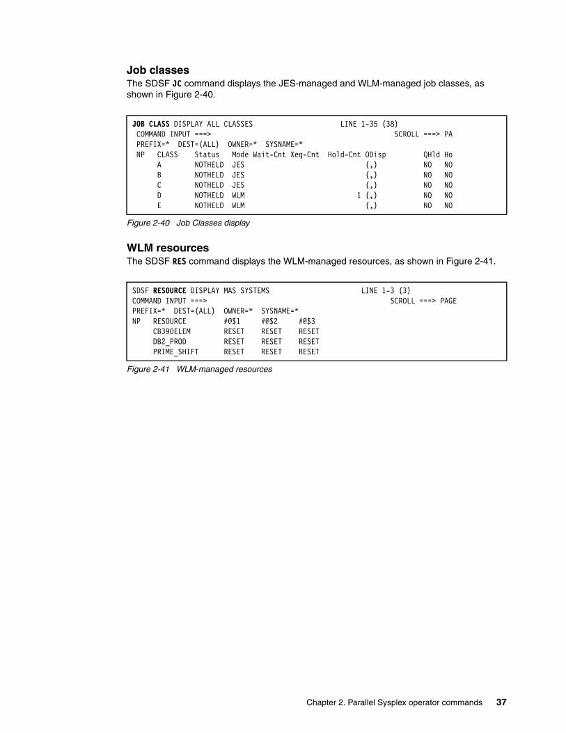
Job classesThe SDSF JC command displays the JES-managed and WLM-managed job classes, as shown in Figure 2-40.
Figure 2-40 Job Classes display
WLM resourcesThe SDSF RES command displays the WLM-managed resources, as shown in Figure 2-41.
Figure 2-41 WLM-managed resources
JOB CLASS DISPLAY ALL CLASSES LINE 1-35 (38) COMMAND INPUT ===> SCROLL ===> PA PREFIX=* DEST=(ALL) OWNER=* SYSNAME=* NP CLASS Status Mode Wait-Cnt Xeq-Cnt Hold-Cnt ODisp QHld Ho A NOTHELD JES (,) NO NO B NOTHELD JES (,) NO NO C NOTHELD JES (,) NO NO D NOTHELD WLM 1 (,) NO NO E NOTHELD WLM (,) NO NO
SDSF RESOURCE DISPLAY MAS SYSTEMS LINE 1-3 (3) COMMAND INPUT ===> SCROLL ===> PAGE PREFIX=* DEST=(ALL) OWNER=* SYSNAME=* NP RESOURCE #@$1 #@$2 #@$3 CB390ELEM RESET RESET RESET DB2_PROD RESET RESET RESET PRIME_SHIFT RESET RESET RESET
Chapter 2. Parallel Sysplex operator commands 37

38 IBM z/OS Parallel Sysplex Operational Scenarios

Chapter 3. IPLing systems in a Parallel Sysplex
This chapter explains the process of IPLing a z/OS system image so that it can join a Parallel Sysplex.
The chapter concentrates on three areas:
� IPLing the first system image in a Parallel Sysplex
� IPLing an additional system image in a Parallel Sysplex
� Possible IPL problems in a Parallel Sysplex
3
© Copyright IBM Corp. 2009. All rights reserved. 39
3.1 Introduction to IPLing systems in a Parallel Sysplex
Having a Parallel Sysplex introduces a number of differences in the IPL process, compared to base sysplex or non-sysplex environments. This chapter highlights the differences by showing the operator messages and activities that differ within a Parallel Sysplex.
As mentioned, the focus is on the following three areas:
� IPLing the first system image in a Parallel Sysplex
� IPLing an additional system image in a Parallel Sysplex
� Possible IPL problems in a Parallel Sysplex
3.2 IPL overview
When IPLing an image into a Parallel Sysplex, there are four significant stages for operators:
� Performing the load on the processor� z/OS initialization� Subsystem restart� Subsystem workload restart
The descriptions in this chapter follow the system to the point where the z/OS initialization is completed and the system is ready for the restart of subsystems and their workload. For details of these stages, refer to this book's chapters on specific subsystems.
After the load has been performed, z/OS runs through four stages during initialization. These stages are:
� Nucleus Initialization Program (NIP)
� Acquiring the Time Of Day (TOD) from the CEC TOD clock, and verifying that the CEC is in the time mode indicated in the CLOCKxx member
� z/OS joining the Parallel Sysplex
– XCF initialization– Coupling Facility (CF) connection– Global Resource Serialization (GRS) initialization
� Console initialization
Important: Visibility to the logs, actions, and messages shown here may depend on your installation and your type of console, whether 3x74, 2074, OSA-ICC, or HMC.
Before IPLing:
� To avoid receiving messages IXC404I and IXC405D (indicating that other systems are already active in the sysplex), the first system IPLed back into the sysplex should preferably also have been the last one removed from the sysplex.
� We do not recommend that you IPL additional systems at the same time as the first system IPL. Wait until GRS initializes, as indicated by message ISG188I (Ring mode) or message ISG300I (Star mode).
� We also recommend that you try to avoid IPLing multiple systems from the same physical sysres at the same time, to avoid possible sysres contention.
40 IBM z/OS Parallel Sysplex Operational Scenarios
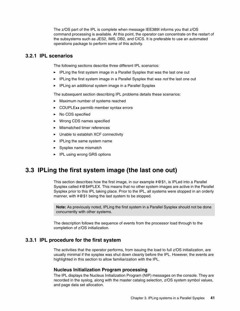
The z/OS part of the IPL is complete when message IEE389I informs you that z/OS command processing is available. At this point, the operator can concentrate on the restart of the subsystems such as JES2, IMS, DB2, and CICS. It is preferable to use an automated operations package to perform some of this activity.
3.2.1 IPL scenarios
The following sections describe three different IPL scenarios:
� IPLing the first system image in a Parallel Sysplex that was the last one out
� IPLing the first system image in a Parallel Sysplex that was not the last one out
� IPLing an additional system image in a Parallel Sysplex
The subsequent section describing IPL problems details these scenarios:
� Maximum number of systems reached
� COUPLExx parmlib member syntax errors
� No CDS specified
� Wrong CDS names specified
� Mismatched timer references
� Unable to establish XCF connectivity
� IPLing the same system name
� Sysplex name mismatch
� IPL using wrong GRS options
3.3 IPLing the first system image (the last one out)
This section describes how the first image, in our example #@$1, is IPLed into a Parallel Sysplex called #@$#PLEX. This means that no other system images are active in the Parallel Sysplex prior to this IPL taking place. Prior to the IPL, all systems were stopped in an orderly manner, with #@$1 being the last system to be stopped..
The description follows the sequence of events from the processor load through to the completion of z/OS initialization.
3.3.1 IPL procedure for the first system
The activities that the operator performs, from issuing the load to full z/OS initialization, are usually minimal if the sysplex was shut down cleanly before the IPL. However, the events are highlighted in this section to allow familiarization with the IPL.
Nucleus Initialization Program processingThe IPL displays the Nucleus Initialization Program (NIP) messages on the console. They are recorded in the syslog, along with the master catalog selection, z/OS system symbol values, and page data set allocation.
Note: As previously noted, IPLing the first system in a Parallel Sysplex should not be done concurrently with other systems.
Chapter 3. IPLing systems in a Parallel Sysplex 41
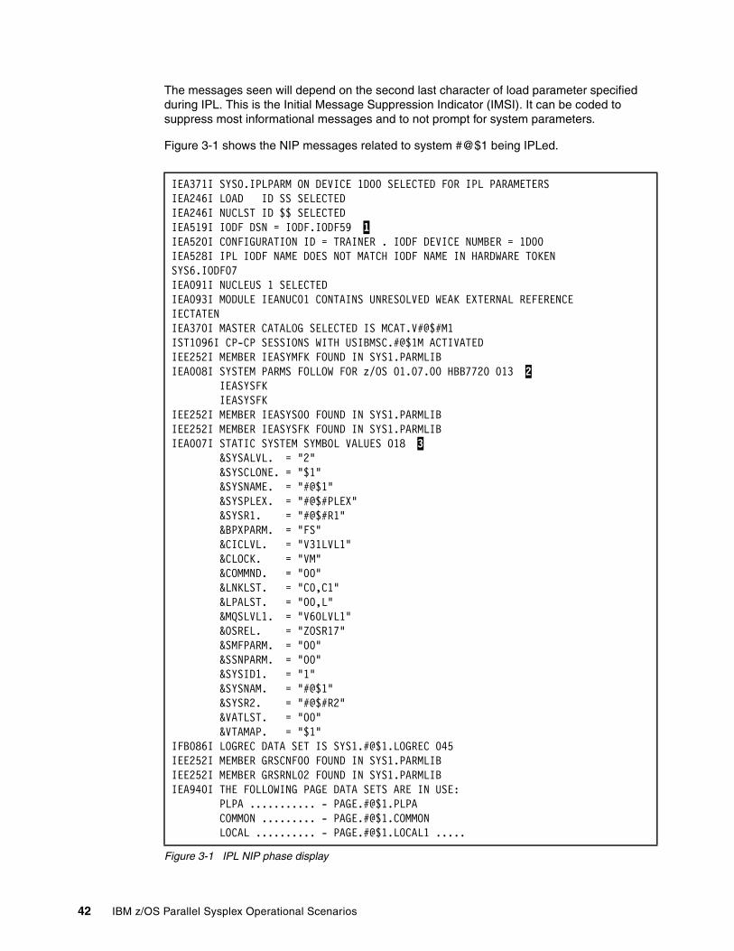
The messages seen will depend on the second last character of load parameter specified during IPL. This is the Initial Message Suppression Indicator (IMSI). It can be coded to suppress most informational messages and to not prompt for system parameters.
Figure 3-1 shows the NIP messages related to system #@$1 being IPLed.
Figure 3-1 IPL NIP phase display
IEA371I SYS0.IPLPARM ON DEVICE 1D00 SELECTED FOR IPL PARAMETERS IEA246I LOAD ID SS SELECTED IEA246I NUCLST ID $$ SELECTED IEA519I IODF DSN = IODF.IODF59 1 IEA520I CONFIGURATION ID = TRAINER . IODF DEVICE NUMBER = 1D00 IEA528I IPL IODF NAME DOES NOT MATCH IODF NAME IN HARDWARE TOKEN SYS6.IODF07 IEA091I NUCLEUS 1 SELECTED IEA093I MODULE IEANUC01 CONTAINS UNRESOLVED WEAK EXTERNAL REFERENCE IECTATEN IEA370I MASTER CATALOG SELECTED IS MCAT.V#@$#M1 IST1096I CP-CP SESSIONS WITH USIBMSC.#@$1M ACTIVATED IEE252I MEMBER IEASYMFK FOUND IN SYS1.PARMLIB IEA008I SYSTEM PARMS FOLLOW FOR z/OS 01.07.00 HBB7720 013 2 IEASYSFK IEASYSFK IEE252I MEMBER IEASYS00 FOUND IN SYS1.PARMLIB IEE252I MEMBER IEASYSFK FOUND IN SYS1.PARMLIB IEA007I STATIC SYSTEM SYMBOL VALUES 018 3 &SYSALVL. = "2" &SYSCLONE. = "$1" &SYSNAME. = "#@$1" &SYSPLEX. = "#@$#PLEX" &SYSR1. = "#@$#R1" &BPXPARM. = "FS"
&CICLVL. = "V31LVL1" &CLOCK. = "VM" &COMMND. = "00"
&LNKLST. = "C0,C1" &LPALST. = "00,L" &MQSLVL1. = "V60LVL1" &OSREL. = "ZOSR17" &SMFPARM. = "00" &SSNPARM. = "00" &SYSID1. = "1" &SYSNAM. = "#@$1" &SYSR2. = "#@$#R2"
&VATLST. = "00" &VTAMAP. = "$1" IFB086I LOGREC DATA SET IS SYS1.#@$1.LOGREC 045 IEE252I MEMBER GRSCNF00 FOUND IN SYS1.PARMLIB IEE252I MEMBER GRSRNL02 FOUND IN SYS1.PARMLIB IEA940I THE FOLLOWING PAGE DATA SETS ARE IN USE: PLPA ........... - PAGE.#@$1.PLPA COMMON ......... - PAGE.#@$1.COMMON LOCAL .......... - PAGE.#@$1.LOCAL1 .....
42 IBM z/OS Parallel Sysplex Operational Scenarios

The messages in Figure 3-1 on page 42 include information that is valuable to the operator:
1 The IODF DSN (and below it, the device number)2 The version of z/OS that is being IPLed 3 The system symbol name and their values
The usual z/OS library loading and concatenation messages then follow; Figure 3-2 shows an example of the messages displayed during this phase. The usual pause in the IPL message flow follows at this point, while the LPA is built.
Figure 3-2 IPL LPA library concatenation
Time-Of-Day (TOD) clock settingThe next milestone in the IPL process is when the system reaches the point where the system TOD clock is initialized. Any offset from the system TOD value is applied.
Part of this processing involves checking that this system is attached to the same time source (Sysplex Timer or Server Time Protocol) as all the other members of the sysplex.
If all systems in the sysplex are run in LPARs on a single CEC, then a simulated timer (SIMETR) can be used.
Figure 3-3 shows the message for the time zone setting.
.
Figure 3-3 Time zone offset setting
Joining (initializing) the sysplexAt this point in the IPL, XCF checks to see if there are active members in the sysplex being joined. Depending on how the sysplex was stopped, the sysplex CDS may show that other members of the sysplex are still active. However, for this example, the systems were shut down cleanly, and the system being IPLed was the last one shut down, so there are no other systems that show a status of ACTIVE in the sysplex CDS. As a result, no alert is issued and the IPL proceeds.
XCF next starts its links to the CF. As each link successfully connects to the CF, message IXL157I is issued, as shown in Figure 3-4 on page 44.
IEE252I MEMBER LPALST00 FOUND IN SYS1.PARMLIBIEA713I LPALST LIBRARY CONCATENATION SYS1.LPALIB
IEA598I TIME ZONE = W.04.00.00
Chapter 3. IPLing systems in a Parallel Sysplex 43
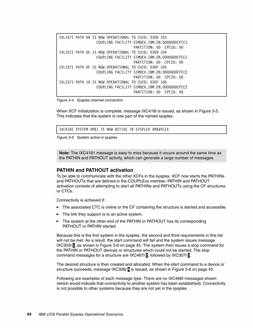
Figure 3-4 Sysplex channel connection
When XCF initialization is complete, message IXC418I is issued, as shown in Figure 3-5. This indicates that the system is now part of the named sysplex.
Figure 3-5 System active in sysplex
PATHIN and PATHOUT activationTo be able to communicate with the other XCFs in the sysplex, XCF now starts the PATHINs and PATHOUTs that are defined in the COUPLExx member. PATHIN and PATHOUT activation consists of attempting to start all PATHINs and PATHOUTs using the CF structures or CTCs.
Connectivity is achieved if:
� The associated CTC is online or the CF containing the structure is started and accessible.
� The link they support is to an active system.
� The system at the other end of the PATHIN or PATHOUT has its corresponding PATHOUT or PATHIN started.
Because this is the first system in the sysplex, the second and third requirements in this list will not be met. As a result, the start command will fail and the system issues message IXC305I 1, as shown in Figure 3-6 on page 45. The system then issues a stop command for the PATHIN or PATHOUT devices or structures which could not be started. The stop command messages for a structure are IXC467I 2, followed by IXC307I 3.
The desired structure is then created and allocated. When the start command to a device or structure succeeds, message IXC306I 4 is issued, as shown in Figure 3-6 on page 45.
Following are examples of each message type. There are no IXC466I messages shown (which would indicate that connectivity to another system has been established). Connectivity is not possible to other systems because they are not yet in the sysplex.
IXL157I PATH 09 IS NOW OPERATIONAL TO CUID: 0309 103 COUPLING FACILITY SIMDEV.IBM.EN.0000000CFCC1 PARTITION: 00 CPCID: 00 IXL157I PATH 0E IS NOW OPERATIONAL TO CUID: 0309 104 COUPLING FACILITY SIMDEV.IBM.EN.0000000CFCC1 PARTITION: 00 CPCID: 00 IXL157I PATH 0F IS NOW OPERATIONAL TO CUID: 030F 105 COUPLING FACILITY SIMDEV.IBM.EN.0000000CFCC2 PARTITION: 00 CPCID: 00 IXL157I PATH 10 IS NOW OPERATIONAL TO CUID: 030F 106 COUPLING FACILITY SIMDEV.IBM.EN.0000000CFCC2 PARTITION: 00 CPCID: 00
IXC418I SYSTEM #@$1 IS NOW ACTIVE IN SYSPLEX #@$#PLEX
Note: The IXC4181 message is easy to miss because it occurs around the same time as the PATHIN and PATHOUT activity, which can generate a large number of messages.
44 IBM z/OS Parallel Sysplex Operational Scenarios

Figure 3-6 Starting PATHs to devices and structures
When the other systems are IPLed and start their end of the paths, communication will be possible with other systems in the Parallel Sysplex.
Couple Data Set addition and structure allocationThe “function” Couple Data Sets are added progressively during Parallel Sysplex activation. This is shown by message IXC286I for each CDS. Depending on your installation, it may include any or all of the CFRM, SFM, BPXMCDS, WLM, LOGR, and ARM Couple Data Sets. Figure 3-7 shows the messages for the CFRM Couple Data Sets.
Figure 3-7 Adding Couple Data Sets
When the SFM CDS is added, if the SFM policy is active, it generates messages IXC602I, IXC609I, and IXC601I. These indicate which policy is loaded and which attributes are used. These messages are shown in Figure 3-8.
Figure 3-8 Adding SFM policy
IXC305I START PATHOUT REQUEST FOR STRUCTURE IXC_DEFAULT_2 103 1 WAS NOT SUCCESSFUL: DELAYED UNTIL AN ACTIVE SYSTEM ALLOCATES STRUCTURE DIAG073:086F0004 00000002 00000008 00071007 00000000 IXC467I STOPPING PATHIN STRUCTURE IXC_DEFAULT_2 104 2 RSN: START REQUEST FAILED DIAG073: 086F0004 00000002 00000008 00071007 00000000 IXC307I STOP PATHOUT REQUEST FOR STRUCTURE IXC_DEFAULT_2 106 3 COMPLETED SUCCESSFULLY: START REQUEST FAILED ...IXC582I STRUCTURE IXC_DEFAULT_2 ALLOCATED BY SIZE/RATIOS....IXC306I START PATHOUT REQUEST FOR STRUCTURE IXC_DEFAULT_2 148 4 COMPLETED SUCCESSFULLY: COUPLING FACILITY RESOURCES AVAILABLE IXC306I START PATHIN REQUEST FOR STRUCTURE IXC_DEFAULT_2 149 COMPLETED SUCCESSFULLY: COUPLING FACILITY RESOURCES AVAILABLE
IXC286I COUPLE DATA SET 128 SYS1.XCF.CFRM01, VOLSER #@$#X2, HAS BEEN ADDED AS THE PRIMARY FOR CFRM ON SYSTEM #@$1 IXC286I COUPLE DATA SET 129 SYS1.XCF.CFRM02, VOLSER #@$#X1, HAS BEEN ADDED AS THE ALTERNATE FOR CFRM ON SYSTEM #@$1
IXC602I SFM POLICY SFM01 INDICATES FOR SYSTEM #@$1 A STATUS 060 UPDATE MISSING ACTION OF ISOLATE AND AN INTERVAL OF 0 SECONDS. THE ACTION WAS SPECIFIED FOR THIS SYSTEM. IXC609I SFM POLICY SFM01 INDICATES FOR SYSTEM #@$1 A SYSTEM WEIGHT OF80 SPECIFIED BY SPECIFIC POLICY ENTRY IXC601I SFM POLICY SFM01 HAS BEEN MADE CURRENT ON SYSTEM #@$1
Chapter 3. IPLing systems in a Parallel Sysplex 45
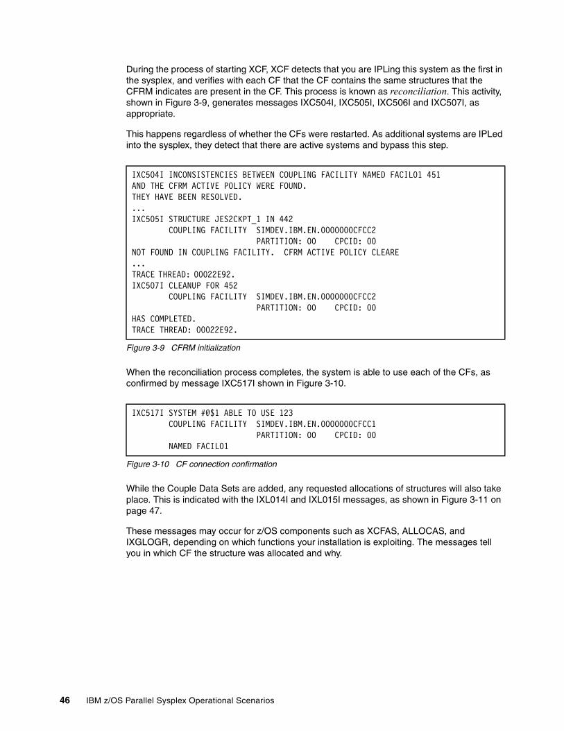
During the process of starting XCF, XCF detects that you are IPLing this system as the first in the sysplex, and verifies with each CF that the CF contains the same structures that the CFRM indicates are present in the CF. This process is known as reconciliation. This activity, shown in Figure 3-9, generates messages IXC504I, IXC505I, IXC506I and IXC507I, as appropriate.
This happens regardless of whether the CFs were restarted. As additional systems are IPLed into the sysplex, they detect that there are active systems and bypass this step.
Figure 3-9 CFRM initialization
When the reconciliation process completes, the system is able to use each of the CFs, as confirmed by message IXC517I shown in Figure 3-10.
Figure 3-10 CF connection confirmation
While the Couple Data Sets are added, any requested allocations of structures will also take place. This is indicated with the IXL014I and IXL015I messages, as shown in Figure 3-11 on page 47.
These messages may occur for z/OS components such as XCFAS, ALLOCAS, and IXGLOGR, depending on which functions your installation is exploiting. The messages tell you in which CF the structure was allocated and why.
IXC504I INCONSISTENCIES BETWEEN COUPLING FACILITY NAMED FACIL01 451 AND THE CFRM ACTIVE POLICY WERE FOUND. THEY HAVE BEEN RESOLVED. ...IXC505I STRUCTURE JES2CKPT_1 IN 442 COUPLING FACILITY SIMDEV.IBM.EN.0000000CFCC2 PARTITION: 00 CPCID: 00 NOT FOUND IN COUPLING FACILITY. CFRM ACTIVE POLICY CLEARE...TRACE THREAD: 00022E92. IXC507I CLEANUP FOR 452 COUPLING FACILITY SIMDEV.IBM.EN.0000000CFCC2 PARTITION: 00 CPCID: 00 HAS COMPLETED. TRACE THREAD: 00022E92.
IXC517I SYSTEM #@$1 ABLE TO USE 123 COUPLING FACILITY SIMDEV.IBM.EN.0000000CFCC1 PARTITION: 00 CPCID: 00 NAMED FACIL01
46 IBM z/OS Parallel Sysplex Operational Scenarios
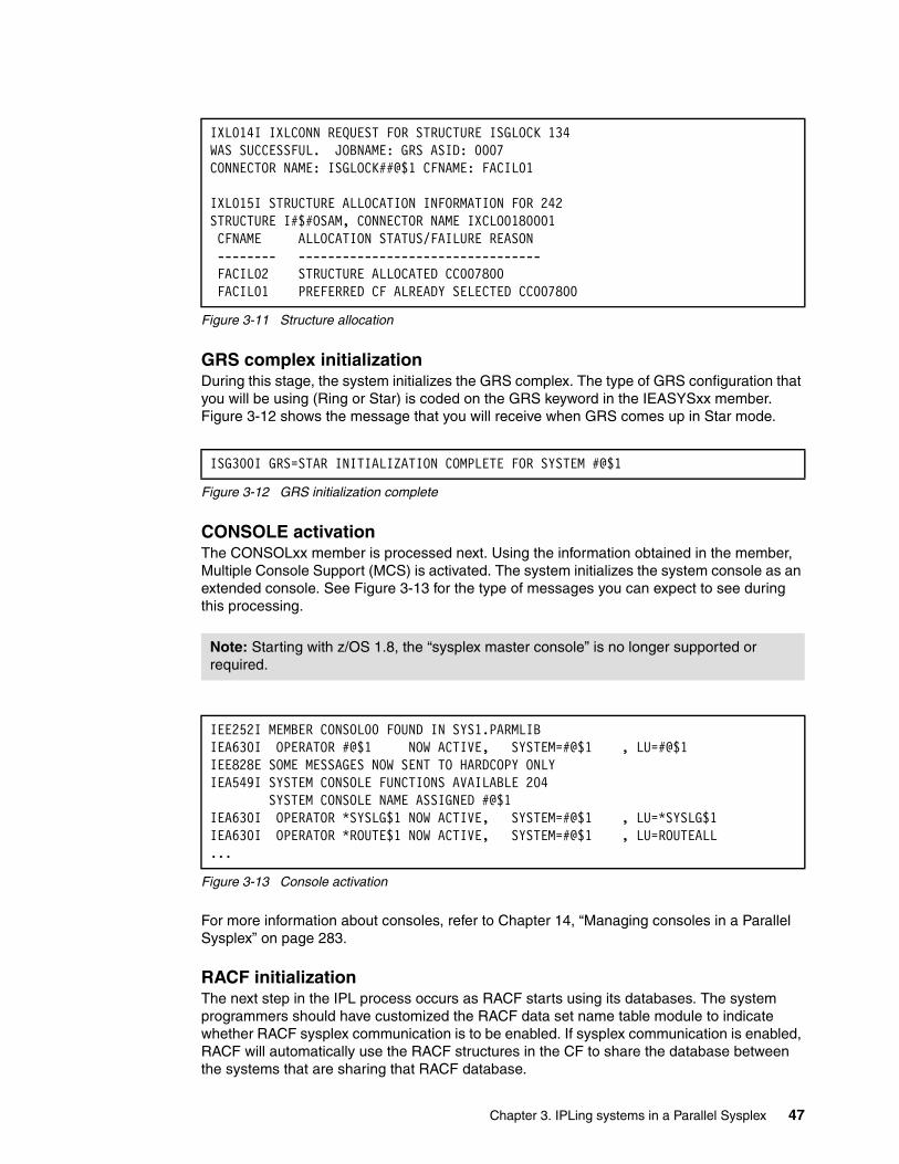
Figure 3-11 Structure allocation
GRS complex initializationDuring this stage, the system initializes the GRS complex. The type of GRS configuration that you will be using (Ring or Star) is coded on the GRS keyword in the IEASYSxx member. Figure 3-12 shows the message that you will receive when GRS comes up in Star mode.
Figure 3-12 GRS initialization complete
CONSOLE activationThe CONSOLxx member is processed next. Using the information obtained in the member, Multiple Console Support (MCS) is activated. The system initializes the system console as an extended console. See Figure 3-13 for the type of messages you can expect to see during this processing.
Figure 3-13 Console activation
For more information about consoles, refer to Chapter 14, “Managing consoles in a Parallel Sysplex” on page 283.
RACF initializationThe next step in the IPL process occurs as RACF starts using its databases. The system programmers should have customized the RACF data set name table module to indicate whether RACF sysplex communication is to be enabled. If sysplex communication is enabled, RACF will automatically use the RACF structures in the CF to share the database between the systems that are sharing that RACF database.
IXL014I IXLCONN REQUEST FOR STRUCTURE ISGLOCK 134WAS SUCCESSFUL. JOBNAME: GRS ASID: 0007 CONNECTOR NAME: ISGLOCK##@$1 CFNAME: FACIL01
IXL015I STRUCTURE ALLOCATION INFORMATION FOR 242 STRUCTURE I#$#OSAM, CONNECTOR NAME IXCLO0180001 CFNAME ALLOCATION STATUS/FAILURE REASON -------- --------------------------------- FACIL02 STRUCTURE ALLOCATED CC007800 FACIL01 PREFERRED CF ALREADY SELECTED CC007800
ISG300I GRS=STAR INITIALIZATION COMPLETE FOR SYSTEM #@$1
Note: Starting with z/OS 1.8, the “sysplex master console” is no longer supported or required.
IEE252I MEMBER CONSOL00 FOUND IN SYS1.PARMLIB IEA630I OPERATOR #@$1 NOW ACTIVE, SYSTEM=#@$1 , LU=#@$1 IEE828E SOME MESSAGES NOW SENT TO HARDCOPY ONLY IEA549I SYSTEM CONSOLE FUNCTIONS AVAILABLE 204 SYSTEM CONSOLE NAME ASSIGNED #@$1 IEA630I OPERATOR *SYSLG$1 NOW ACTIVE, SYSTEM=#@$1 , LU=*SYSLG$1IEA630I OPERATOR *ROUTE$1 NOW ACTIVE, SYSTEM=#@$1 , LU=ROUTEALL...
Chapter 3. IPLing systems in a Parallel Sysplex 47
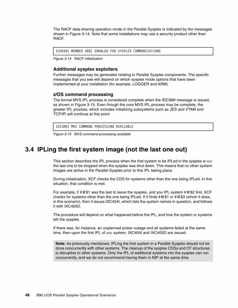
The RACF data-sharing operation mode in the Parallel Sysplex is indicated by the messages shown in Figure 3-14. Note that some installations may use a security product other than RACF.
Figure 3-14 RACF initialization
Additional sysplex exploitersFurther messages may be generated relating to Parallel Sysplex components. The specific messages that you see will depend on which sysplex mode options that have been implemented at your installation (for example, LOGGER and ARM).
z/OS command processingThe formal MVS IPL process is considered complete when the IEE389I message is issued, as shown in Figure 3-15. Even though the core MVS IPL process may be complete, the greater IPL process, which includes initializing subsystems such as JES and VTAM and TCP/IP, will continue at this point.
Figure 3-15 MVS command processing available
3.4 IPLing the first system image (not the last one out)
This section describes the IPL process when the first system to be IPLed in the sysplex is not the last one to be stopped when the sysplex was shut down. This means that no other system images are active in the Parallel Sysplex prior to this IPL taking place.
During initialization, XCF checks the CDS for systems other than the one being IPLed. In this situation, that condition is met.
For example, if #@$1 was the last to leave the sysplex, and you IPL system #@$2 first, XCF checks for systems other than the one being IPLed. If it finds #@$1 or #@$3 (which it does, in this scenario), then it issues IXC404I, which lists the system names in question, and follows it with IXC405D.
The procedure will depend on what happened before the IPL, and how the system or systems left the sysplex.
If there was, for instance, an unplanned power outage and all systems failed at the same time, then upon the first IPL of any system, IXC404I and IXC405D are issued.
ICH559I MEMBER #@$1 ENABLED FOR SYSPLEX COMMUNICATIONS
IEE389I MVS COMMAND PROCESSING AVAILABLE
Note: As previously mentioned, IPLing the first system in a Parallel Sysplex should not be done concurrently with other systems. The cleanup of the sysplex CDSs and CF structures is disruptive to other systems. Only the IPL of additional systems into the sysplex can run concurrently, and we do not recommend having them in NIP at the same time.
48 IBM z/OS Parallel Sysplex Operational Scenarios
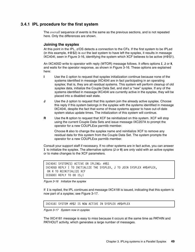
3.4.1 IPL procedure for the first system
The overall sequence of events is the same as the previous sections, and is not repeated here. Only the differences are shown.
Joining the sysplexAt this point in the IPL, z/OS detects a connection to the CFs. If the first system to be IPLed (in this example, #@$2) is not the last system to have left the sysplex, it results in message IXC404I, seen in Figure 3-16, identifying the system which XCF believes to be active (#@$1).
An IXC405D write to operator with reply (WTOR) message follows. It offers options I, J or R, and waits for the operator response, as shown in Figure 3-16. These options are explained here:
I Use the I option to request that sysplex initialization continue because none of the systems identified in message IXC404I are in fact participating in an operating sysplex; that is, they are all residual systems. This system will perform cleanup of old sysplex data, initialize the Couple Data Set, and start a “new” sysplex. If any of the systems identified in message IXC404I are currently active in the sysplex, they will be placed into a disabled wait state.
J Use the J option to request that this system join the already active sysplex. Choose this reply if this system belongs in the sysplex with the systems identified in message IXC404I, despite the fact that some of those systems appear to have out-of-date system status update times. The initialization of this system will continue.
R Use the R option to request that XCF be reinitialized on this system. XCF will stop using the current Couple Data Sets and issue message IXC207A to prompt the operator for a new COUPLExx parmlib member.
Choose R also to change the sysplex name and reinitialize XCF to remove any residual data for this system from the Couple Data Set. The system prompts the operator for a new COUPLExx parmlib member.
Consult your support staff if necessary. If no other systems are in fact active, you can answer I to initialize the sysplex. The alternative options (J or R) are only valid with an active sysplex or to make changes to the XCF parameters.
Figure 3-16 Initialize the sysplex
If I is replied, the IPL continues and message IXC418I is issued, indicating that this system is now part of a sysplex; see Figure 3-17.
Figure 3-17 System now in sysplex
The IXC4181 message is easy to miss because it occurs at the same time as PATHIN and PATHOUT activity, which generates a large number of messages.
IXC404I SYSTEM(S) ACTIVE OR IPLING: #@$1 IXC405D REPLY I TO INITIALIZE THE SYSPLEX, J TO JOIN SYSPLEX #@$#PLEX, OR R TO REINITIALIZE XCF IEE600I REPLY TO 00 IS;I
IXC418I SYSTEM #@$2 IS NOW ACTIVE IN SYSPLEX #@$#PLEX
Chapter 3. IPLing systems in a Parallel Sysplex 49

If you reply J in the preceding scenario, the system being IPLed would join the “active” sysplex. However, after it is running, if the time stamps of the other systems do not become updated, this system may consider them to be in “status update missing (SUM)” condition, and may start partitioning the inactive systems out of the sysplex.
3.5 IPLing any system after any type of shutdown
This section describes how any image is IPLed in a Parallel Sysplex following any type of shutdown. This means that at least one other system image is already active in the Parallel Sysplex prior to this IPL taking place. You are not necessarily coming from a position of a total shutdown or outage in this section.
Again, the actions depend on what happened before this IPL:
� Whether this system was removed from XCF since it was shut down
� Whether this system was not removed from XCF
Note that the overall sequence of events is the same as the previous sections and is not repeated here. Only the differences are shown.
3.5.1 IPL procedure for any additional system in a Parallel Sysplex
TOD clock settingThe active system or systems in the sysplex will already be in their coded timer mode, meaning in ETR, SIMETR, or STP mode. Any other systems trying to join should be coded the same, or at least in a compatible manner.
Timer errors are shown in 3.6.5, “Mismatching timer references” on page 55.
Joining the sysplexThere are two scenarios that may have preceded any IPL into an active sysplex, as explained here.
If the system was removed from XCF since it was stopped or shut downIf the system was removed, then there is no residual presence of this system in the sysplex, and it will join without incident.
If this system was not removed from XCFDuring stopping or shutdown of this additional system, there may have been replies left unanswered in the remaining systems. Examples are shown in Figure 3-18 on page 51.
Note: Under certain circumstances, the sysplex becomes ‘locked’ and message IXC420A might be issued instead of IXC405A. Those circumstances may include during a disaster recovery where the CF name has changed; if CDS specifications for the IPLing system do not appear to match what the current sysplex is using; or if the Sysplex Timers do not appear to be the same.
In these cases, using J to join is not an option. The only choices offered are I to initialize the sysplex, or R to specify a new COUPLExx.
50 IBM z/OS Parallel Sysplex Operational Scenarios
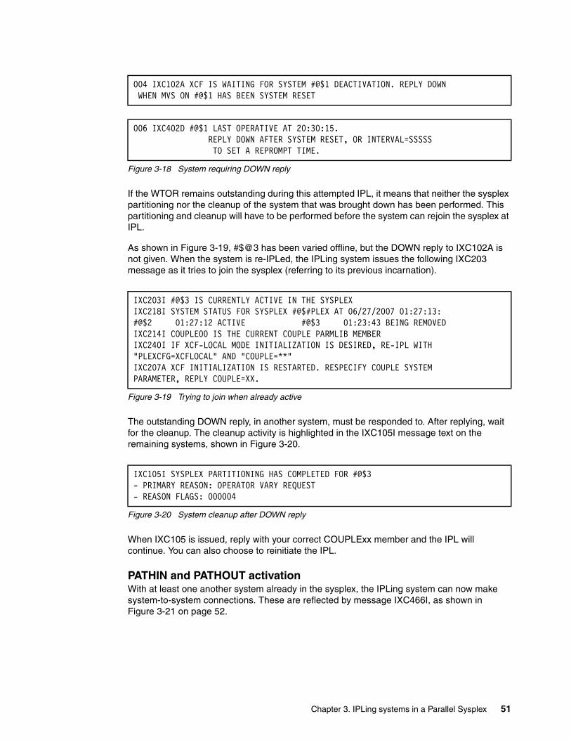
Figure 3-18 System requiring DOWN reply
If the WTOR remains outstanding during this attempted IPL, it means that neither the sysplex partitioning nor the cleanup of the system that was brought down has been performed. This partitioning and cleanup will have to be performed before the system can rejoin the sysplex at IPL.
As shown in Figure 3-19, #$@3 has been varied offline, but the DOWN reply to IXC102A is not given. When the system is re-IPLed, the IPLing system issues the following IXC203 message as it tries to join the sysplex (referring to its previous incarnation).
Figure 3-19 Trying to join when already active
The outstanding DOWN reply, in another system, must be responded to. After replying, wait for the cleanup. The cleanup activity is highlighted in the IXC105I message text on the remaining systems, shown in Figure 3-20.
Figure 3-20 System cleanup after DOWN reply
When IXC105 is issued, reply with your correct COUPLExx member and the IPL will continue. You can also choose to reinitiate the IPL.
PATHIN and PATHOUT activationWith at least one another system already in the sysplex, the IPLing system can now make system-to-system connections. These are reflected by message IXC466I, as shown in Figure 3-21 on page 52.
004 IXC102A XCF IS WAITING FOR SYSTEM #@$1 DEACTIVATION. REPLY DOWN WHEN MVS ON #@$1 HAS BEEN SYSTEM RESET
006 IXC402D #@$1 LAST OPERATIVE AT 20:30:15. REPLY DOWN AFTER SYSTEM RESET, OR INTERVAL=SSSSS TO SET A REPROMPT TIME.
IXC203I #@$3 IS CURRENTLY ACTIVE IN THE SYSPLEX IXC218I SYSTEM STATUS FOR SYSPLEX #@$#PLEX AT 06/27/2007 01:27:13: #@$2 01:27:12 ACTIVE #@$3 01:23:43 BEING REMOVEDIXC214I COUPLE00 IS THE CURRENT COUPLE PARMLIB MEMBER IXC240I IF XCF-LOCAL MODE INITIALIZATION IS DESIRED, RE-IPL WITH "PLEXCFG=XCFLOCAL" AND "COUPLE=**" IXC207A XCF INITIALIZATION IS RESTARTED. RESPECIFY COUPLE SYSTEMPARAMETER, REPLY COUPLE=XX.
IXC105I SYSPLEX PARTITIONING HAS COMPLETED FOR #@$3- PRIMARY REASON: OPERATOR VARY REQUEST - REASON FLAGS: 000004
Chapter 3. IPLing systems in a Parallel Sysplex 51
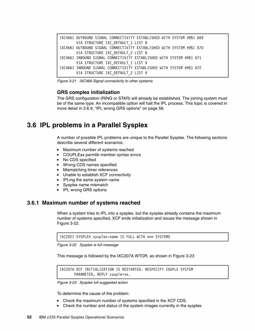
Figure 3-21 IXC466 Signal connectivity to other systems
GRS complex initializationThe GRS configuration (RING or STAR) will already be established. The joining system must be of the same type. An incompatible option will halt the IPL process. This topic is covered in more detail in 3.6.9, “IPL wrong GRS options” on page 58.
3.6 IPL problems in a Parallel Sysplex
A number of possible IPL problems are unique to the Parallel Sysplex. The following sections describe several different scenarios:
� Maximum number of systems reached� COUPLExx parmlib member syntax errors� No CDS specified� Wrong CDS names specified� Mismatching timer references� Unable to establish XCF connectivity � IPLing the same system name� Sysplex name mismatch� IPL wrong GRS options
3.6.1 Maximum number of systems reached
When a system tries to IPL into a sysplex, but the sysplex already contains the maximum number of systems specified, XCF ends initialization and issues the message shown in Figure 3-22.
Figure 3-22 Sysplex is full message
This message is followed by the IXC207A WTOR, as shown in Figure 3-23
Figure 3-23 Sysplex full suggested action
To determine the cause of the problem:
� Check the maximum number of systems specified in the XCF CDS.� Check the number and status of the system images currently in the sysplex.
IXC466I OUTBOUND SIGNAL CONNECTIVITY ESTABLISHED WITH SYSTEM #@$1 669 VIA STRUCTURE IXC_DEFAULT_1 LIST 8 IXC466I OUTBOUND SIGNAL CONNECTIVITY ESTABLISHED WITH SYSTEM #@$1 670 VIA STRUCTURE IXC_DEFAULT_2 LIST 8 IXC466I INBOUND SIGNAL CONNECTIVITY ESTABLISHED WITH SYSTEM #@$1 671 VIA STRUCTURE IXC_DEFAULT_1 LIST 9 IXC466I INBOUND SIGNAL CONNECTIVITY ESTABLISHED WITH SYSTEM #@$1 672 VIA STRUCTURE IXC_DEFAULT_2 LIST 9
IXC202I SYSPLEX sysplex-name IS FULL WITH nnn SYSTEMS
IXC207A XCF INITIALIZATION IS RESTARTED. RESPECIFY COUPLE SYSTEM PARAMETER, REPLY couple=xx.
52 IBM z/OS Parallel Sysplex Operational Scenarios
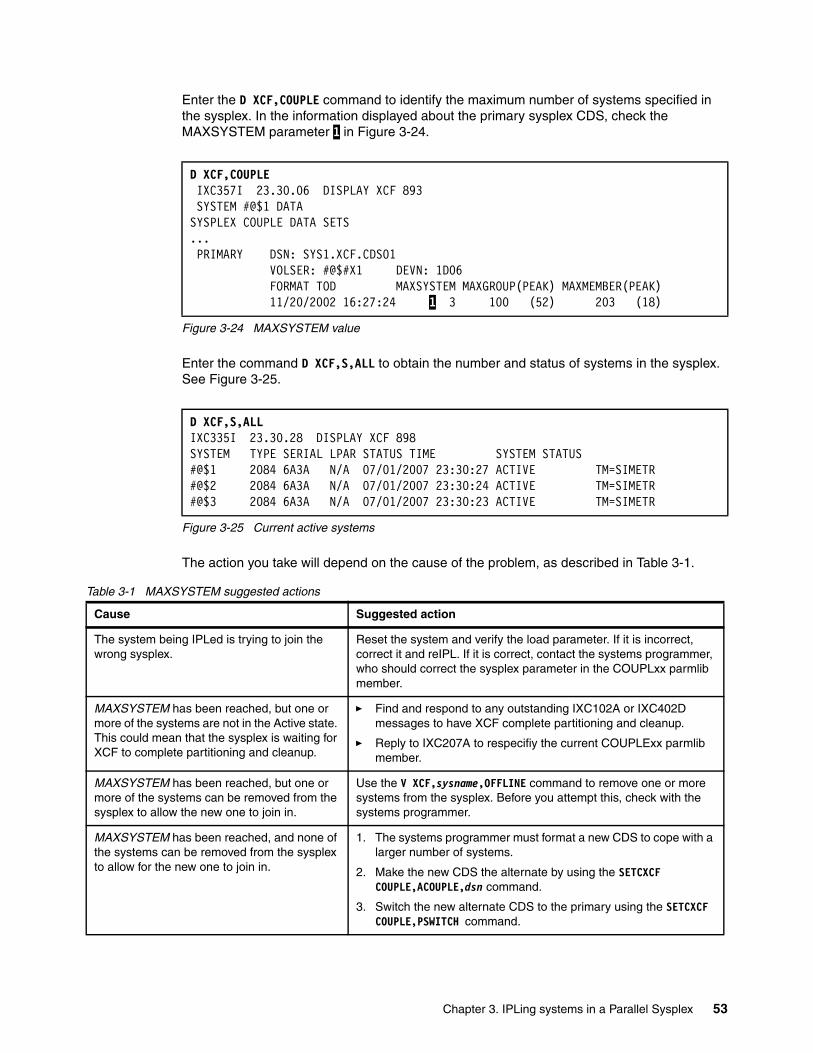
Enter the D XCF,COUPLE command to identify the maximum number of systems specified in the sysplex. In the information displayed about the primary sysplex CDS, check the MAXSYSTEM parameter 1 in Figure 3-24.
Figure 3-24 MAXSYSTEM value
Enter the command D XCF,S,ALL to obtain the number and status of systems in the sysplex. See Figure 3-25.
Figure 3-25 Current active systems
The action you take will depend on the cause of the problem, as described in Table 3-1.
Table 3-1 MAXSYSTEM suggested actions
D XCF,COUPLE IXC357I 23.30.06 DISPLAY XCF 893 SYSTEM #@$1 DATA SYSPLEX COUPLE DATA SETS ... PRIMARY DSN: SYS1.XCF.CDS01 VOLSER: #@$#X1 DEVN: 1D06 FORMAT TOD MAXSYSTEM MAXGROUP(PEAK) MAXMEMBER(PEAK) 11/20/2002 16:27:24 1 3 100 (52) 203 (18)
D XCF,S,ALL IXC335I 23.30.28 DISPLAY XCF 898 SYSTEM TYPE SERIAL LPAR STATUS TIME SYSTEM STATUS #@$1 2084 6A3A N/A 07/01/2007 23:30:27 ACTIVE TM=SIMETR#@$2 2084 6A3A N/A 07/01/2007 23:30:24 ACTIVE TM=SIMETR#@$3 2084 6A3A N/A 07/01/2007 23:30:23 ACTIVE TM=SIMETR
Cause Suggested action
The system being IPLed is trying to join the wrong sysplex.
Reset the system and verify the load parameter. If it is incorrect, correct it and reIPL. If it is correct, contact the systems programmer, who should correct the sysplex parameter in the COUPLxx parmlib member.
MAXSYSTEM has been reached, but one or more of the systems are not in the Active state. This could mean that the sysplex is waiting for XCF to complete partitioning and cleanup.
� Find and respond to any outstanding IXC102A or IXC402D messages to have XCF complete partitioning and cleanup.
� Reply to IXC207A to respecifiy the current COUPLExx parmlib member.
MAXSYSTEM has been reached, but one or more of the systems can be removed from the sysplex to allow the new one to join in.
Use the V XCF,sysname,OFFLINE command to remove one or more systems from the sysplex. Before you attempt this, check with the systems programmer.
MAXSYSTEM has been reached, and none of the systems can be removed from the sysplex to allow for the new one to join in.
1. The systems programmer must format a new CDS to cope with a larger number of systems.
2. Make the new CDS the alternate by using the SETCXCF COUPLE,ACOUPLE,dsn command.
3. Switch the new alternate CDS to the primary using the SETCXCF COUPLE,PSWITCH command.
Chapter 3. IPLing systems in a Parallel Sysplex 53

3.6.2 COUPLExx parmlib member syntax errors
If a system is IPLed with a COUPLExx member containing syntax errors, the IPL will cease at this point and the system could issue any of the messages in Figure 3-26, depending on what the exact problem is, as shown here.
Figure 3-26 Couple data set syntax errors
The text should specify the nature of the error, in some cases specifying the column it occurred in. If the COUPLExx member is the correct one for the IPL, the syntax errors must be corrected before the IPL can complete.
If the IPLing system is using the same COUPLExx member as the existing system or systems, then the COUPLExx must have been changed since they were IPLed. It could, however, be using a different COUPLExx member.
If all systems in the sysplex are sharing their parmlib definitions, the systems programmer should be able to log on to one of the active systems and correct the definitions from there.
When the definitions have been corrected, respond to the IXC201A WTOR with COUPLE=xx, where xx is the suffix of the corrected COUPLExx member in the PARMLIB. You may choose to start the IPL again.
If the problems cannot be corrected from another system, you must IPL the failing system in XCF-local mode. Before you attempt this, check with the systems programmer. After e the system has completed the IPL, the systems programmer will be able to analyze and correct the problem.
3.6.3 No CDS specified
XCF requires a primary sysplex CDS. When the system is IPLing, if XCF does not find any CDS specified in the COUPLExx member, but the PLEXCFG parameter indicates a monoplex or multisystem configuration, the messages shown in Figure 3-27 on page 55 are issued.
IXC205I SYNTAX ERROR IN COUPLExx: text (such as incorrect parentheses)
IXC206I THE COUPLExx text (such as incorrect keyword)
IXC211A SYNTAX ERROR IN COUPLE SYSTEM PARAMETER. REPLY COUPLE=XX
Note: To IPL in XCF-local mode, we recommend that an installation maintains an alternate COUPLExx member in the PARMLIB containing the definition COUPLE SYSPLEX(LOCAL).
54 IBM z/OS Parallel Sysplex Operational Scenarios
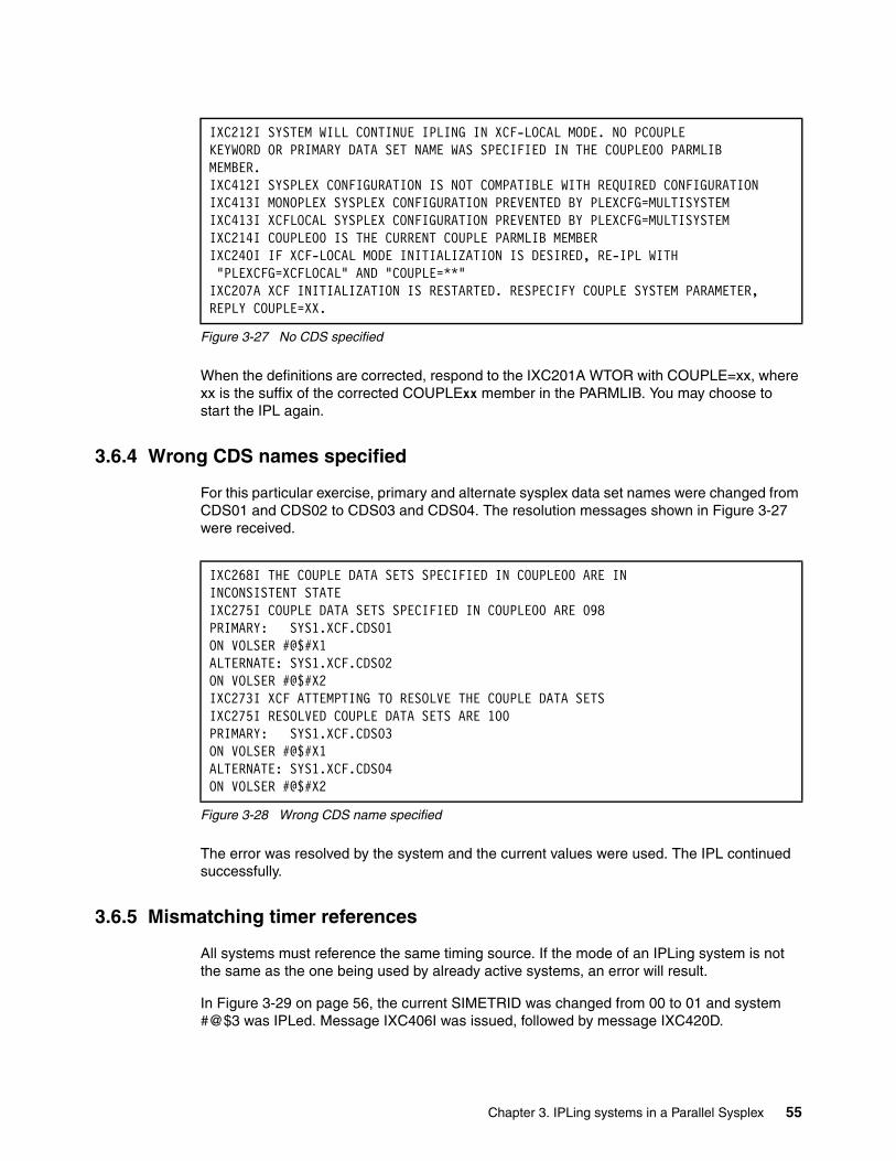
Figure 3-27 No CDS specified
When the definitions are corrected, respond to the IXC201A WTOR with COUPLE=xx, where xx is the suffix of the corrected COUPLExx member in the PARMLIB. You may choose to start the IPL again.
3.6.4 Wrong CDS names specified
For this particular exercise, primary and alternate sysplex data set names were changed from CDS01 and CDS02 to CDS03 and CDS04. The resolution messages shown in Figure 3-27 were received.
Figure 3-28 Wrong CDS name specified
The error was resolved by the system and the current values were used. The IPL continued successfully.
3.6.5 Mismatching timer references
All systems must reference the same timing source. If the mode of an IPLing system is not the same as the one being used by already active systems, an error will result.
In Figure 3-29 on page 56, the current SIMETRID was changed from 00 to 01 and system #@$3 was IPLed. Message IXC406I was issued, followed by message IXC420D.
IXC212I SYSTEM WILL CONTINUE IPLING IN XCF-LOCAL MODE. NO PCOUPLE KEYWORD OR PRIMARY DATA SET NAME WAS SPECIFIED IN THE COUPLE00 PARMLIB MEMBER. IXC412I SYSPLEX CONFIGURATION IS NOT COMPATIBLE WITH REQUIRED CONFIGURATION IXC413I MONOPLEX SYSPLEX CONFIGURATION PREVENTED BY PLEXCFG=MULTISYSTEM IXC413I XCFLOCAL SYSPLEX CONFIGURATION PREVENTED BY PLEXCFG=MULTISYSTEM IXC214I COUPLE00 IS THE CURRENT COUPLE PARMLIB MEMBER IXC240I IF XCF-LOCAL MODE INITIALIZATION IS DESIRED, RE-IPL WITH "PLEXCFG=XCFLOCAL" AND "COUPLE=**" IXC207A XCF INITIALIZATION IS RESTARTED. RESPECIFY COUPLE SYSTEM PARAMETER, REPLY COUPLE=XX.
IXC268I THE COUPLE DATA SETS SPECIFIED IN COUPLE00 ARE IN INCONSISTENT STATE IXC275I COUPLE DATA SETS SPECIFIED IN COUPLE00 ARE 098 PRIMARY: SYS1.XCF.CDS01 ON VOLSER #@$#X1 ALTERNATE: SYS1.XCF.CDS02 ON VOLSER #@$#X2 IXC273I XCF ATTEMPTING TO RESOLVE THE COUPLE DATA SETS IXC275I RESOLVED COUPLE DATA SETS ARE 100 PRIMARY: SYS1.XCF.CDS03 ON VOLSER #@$#X1 ALTERNATE: SYS1.XCF.CDS04 ON VOLSER #@$#X2
Chapter 3. IPLing systems in a Parallel Sysplex 55
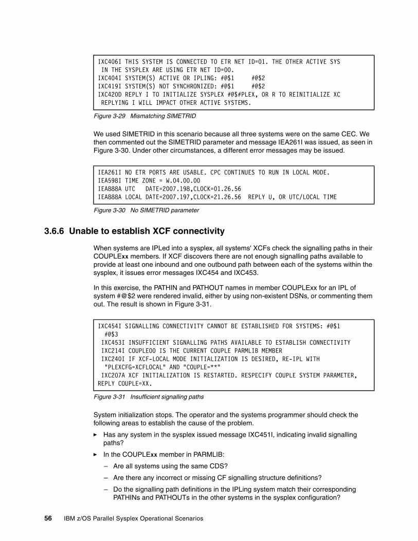
Figure 3-29 Mismatching SIMETRID
We used SIMETRID in this scenario because all three systems were on the same CEC. We then commented out the SIMETRID parameter and message IEA261I was issued, as seen in Figure 3-30. Under other circumstances, a different error messages may be issued.
Figure 3-30 No SIMETRID parameter
3.6.6 Unable to establish XCF connectivity
When systems are IPLed into a sysplex, all systems' XCFs check the signalling paths in their COUPLExx members. If XCF discovers there are not enough signalling paths available to provide at least one inbound and one outbound path between each of the systems within the sysplex, it issues error messages IXC454 and IXC453.
In this exercise, the PATHIN and PATHOUT names in member COUPLExx for an IPL of system #@$2 were rendered invalid, either by using non-existent DSNs, or commenting them out. The result is shown in Figure 3-31.
Figure 3-31 Insufficient signalling paths
System initialization stops. The operator and the systems programmer should check the following areas to establish the cause of the problem.
� Has any system in the sysplex issued message IXC451I, indicating invalid signalling paths?
� In the COUPLExx member in PARMLIB:
– Are all systems using the same CDS?
– Are there any incorrect or missing CF signalling structure definitions?
– Do the signalling path definitions in the IPLing system match their corresponding PATHINs and PATHOUTs in the other systems in the sysplex configuration?
IXC406I THIS SYSTEM IS CONNECTED TO ETR NET ID=01. THE OTHER ACTIVE SYS IN THE SYSPLEX ARE USING ETR NET ID=00. IXC404I SYSTEM(S) ACTIVE OR IPLING: #@$1 #@$2 IXC419I SYSTEM(S) NOT SYNCHRONIZED: #@$1 #@$2 IXC420D REPLY I TO INITIALIZE SYSPLEX #@$#PLEX, OR R TO REINITIALIZE XC REPLYING I WILL IMPACT OTHER ACTIVE SYSTEMS.
IEA261I NO ETR PORTS ARE USABLE. CPC CONTINUES TO RUN IN LOCAL MODE. IEA598I TIME ZONE = W.04.00.00 IEA888A UTC DATE=2007.198,CLOCK=01.26.56 IEA888A LOCAL DATE=2007.197,CLOCK=21.26.56 REPLY U, OR UTC/LOCAL TIME
IXC454I SIGNALLING CONNECTIVITY CANNOT BE ESTABLISHED FOR SYSTEMS: #@$1 #@$3 IXC453I INSUFFICIENT SIGNALLING PATHS AVAILABLE TO ESTABLISH CONNECTIVITY IXC214I COUPLE00 IS THE CURRENT COUPLE PARMLIB MEMBER IXC240I IF XCF-LOCAL MODE INITIALIZATION IS DESIRED, RE-IPL WITH "PLEXCFG=XCFLOCAL" AND "COUPLE=**" IXC207A XCF INITIALIZATION IS RESTARTED. RESPECIFY COUPLE SYSTEM PARAMETER, REPLY COUPLE=XX.
56 IBM z/OS Parallel Sysplex Operational Scenarios
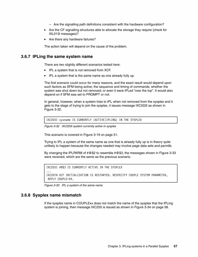
– Are the signalling path definitions consistent with the hardware configuration?
� Are the CF signalling structures able to allocate the storage they require (check for IXL013I messages)?
� Are there any hardware failures?
The action taken will depend on the cause of the problem.
3.6.7 IPLing the same system name
There are two slightly different scenarios tested here:
� IPL a system that is not removed from XCF.
� IPL a system that is the same name as one already fully up.
The first scenario could occur for many reasons, and the exact result would depend upon such factors as SFM being active; the sequence and timing of commands; whether the system was shut down but not removed; or even it were IPLed “over the top”. It would also depend on if SFM was set to PROMPT or not.
In general, however, when a system tries to IPL when not removed from the sysplex and it gets to the stage of trying to join the sysplex, it issues message IXC203I as shown in Figure 3-32.
Figure 3-32 IXC203I system currently active in sysplex
This scenario is covered in Figure 3-19 on page 51.
Trying to IPL a system of the same name as one that is already fully up is in theory quite unlikely to happen because the changes needed may involve page data sets and parmlib.
By changing the IPLPARM of #@$2 to resemble #@$3, the messages shown in Figure 3-33 were received, which are the same as the previous scenario.
Figure 3-33 IPL a system of the same name
3.6.8 Sysplex name mismatch
If the sysplex name in COUPLExx does not match the name of the sysplex that the IPLing system is joining, then message IXC255 is issued as shown in Figure 3-34 on page 58.
IXC203I sysname IS CURRENTLY {ACTIVE¦IPLING} IN THE SYSPLEX
IXC203I #@$3 IS CURRENTLY ACTIVE IN THE SYSPLEX ...IXC207A XCF INITIALIZATION IS RESTARTED. RESPECIFY COUPLE SYSTEM PARAMETER, REPLY COUPLE=XX.
Chapter 3. IPLing systems in a Parallel Sysplex 57
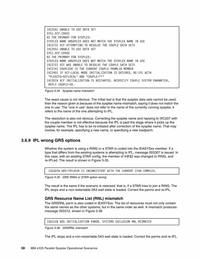
Figure 3-34 Sysplex name mismatch
The exact cause is not obvious. The initial text is that the sysplex data sets cannot be used, then the reason given is because of the sysplex name mismatch, saying it does not match the one in use. The “one in use” does not refer to the name of the currently running sysplex, it refers to the name of the one attempting to IPL.
The resolution is also not obvious. Correcting the sysplex name and replying to IXC207 with the couple member is not effective because the IPL is past the stage where it picks up the sysplex name. The IPL has to be re-initiated after correction of the sysplex name. That may involve, for example, specifying a new name, or specifying a new loadparm.
3.6.9 IPL wrong GRS options
Whether the system is using a RING or a STAR is coded into the IEASYSxx member. If a type that differs from the existing systems is attempting to IPL, message ISG307 is issued. In this case, with an existing STAR config, the member of #@$2 was changed to RING, and re-IPLed. The result is shown in Figure 3-35.
Figure 3-35 GRS RING or STAR option wrong
The result is the same if the scenario is reversed; that is, if a STAR tries to join a RING. The IPL stops and a non-restartable 0A3 wait state is loaded. Correct the parms and re-IPL.
GRS Resource Name List (RNL) mismatchThe GRSRNL parm is also coded in IEASYSxx. The list of resources must not only contain the same names as the other systems, but in the same order as well. A mismatch produces message ISG312, shown in Figure 3-36
Figure 3-36 GRSRNL mismatch
The IPL stops and a non-restartable 0A3 wait state is loaded. Correct the parms and re-IPL.
IXC255I UNABLE TO USE DATA SET SYS1.XCF.CDS01 AS THE PRIMARY FOR SYSPLEX: SYSPLEX NAME #@$#PLEX DOES NOT MATCH THE SYSPLEX NAME IN USE IXC273I XCF ATTEMPTING TO RESOLVE THE COUPLE DATA SETS IXC255I UNABLE TO USE DATA SET SYS1.XCF.CDS02 AS THE PRIMARY FOR SYSPLEX: SYSPLEX NAME #@$#PLEX DOES NOT MATCH THE SYSPLEX NAME IN USE IXC272I XCF WAS UNABLE TO RESOLVE THE COUPLE DATA SETS IXC214I COUPLE00 IS THE CURRENT COUPLE PARMLIB MEMBER IXC240I IF XCF-LOCAL MODE INITIALIZATION IS DESIRED, RE-IPL WITH "PLEXCFG=XCFLOCAL" AND "COUPLE=**" IXC207A XCF INITIALIZATION IS RESTARTED. RESPECIFY COUPLE SYSTEM PARAMETER, REPLY COUPLE=XX.
ISG307W GRS=TRYJOIN IS INCONSISTENT WITH THE CURRENT STAR COMPLEX.
ISG312W GRS INITIALIZATION ERROR. SYSTEMS EXCLUSION RNL MISMATCH
58 IBM z/OS Parallel Sysplex Operational Scenarios
Chapter 4. Shutting down z/OS systems in a Parallel Sysplex
This chapter explains how to shut down a z/OS system image in a Parallel Sysplex.
This chapter concentrates on three areas:
� Shutdown overview
� Removing z/OS systems from a Parallel Sysplex
� Running a stand-alone dump (SAD) on a Parallel Sysplex
4
© Copyright IBM Corp. 2009. All rights reserved. 59
4.1 Introduction to z/OS system shutdown in a Parallel Sysplex
The process of shutting down a z/OS image in a Parallel Sysplex is very similar to stopping an image in either a base sysplex or a non-sysplex environment. This chapter highlights the differences by showing the operator messages and activities that differ within a Parallel Sysplex.
As mentioned, the focus here is on the following three areas:
� Shutdown overview� Removing z/OS systems from a Parallel Sysplex� Running a standalone dump (SAD) on a Parallel Sysplex
For reference, messages that are often seen during a system stop (both controlled and uncontrolled) are listed here:
IXC101I SYSPLEX PARTITIONING IN PROGRESS FOR sysname REQUESTED BY jobname REASON: reason
IXC102A XCF IS WAITING FOR SYSTEM sysname DEACTIVATION. REPLY DOWN WHEN MVS ON sysname HAS BEEN SYSTEM RESET.
IXC105I SYSPLEX PARTITIONING HAS COMPLETED FOR sysname - PRIMARY REASON text - REASON FLAGS: flags
IXC371D CONFIRM REQUEST TO VARY SYSTEM sysname OFFLINE. REPLY SYSNAME=sysname TO REMOVE sysname OR C TO CANCEL.
IXC402D sysname LAST OPERATIVE AT hh:mm:ss. REPLY DOWN AFTER SYSTEM RESET OR INTERVAL=SSSSS TO SET A REPROMPT TIME.
4.2 Shutdown overview
There are many different shutdown and failure scenarios. These include: planned with Sysplex Failure Management (SFM); planned without SFM; manually detected failure; automatically detected failure; and SFM fails to isolate. Some of these scenarios share the same actions and procedures.
There are eight steps involved in a planned shutdown of a z/OS system in a Parallel Sysplex. The scenarios are variations of the basic steps, with differing amounts of operator intervention. Follow your site’s procedures. It is possible to use an automated operations package to perform some of the activities.
1. Shut down the subsystem workload.
2. Shut down the subsystems and possibly restart them on another system.
3. Shut down z/OS.
4. Remove the system from the Parallel Sysplex by issuing:
VARY XCF,sysname,OFFLINE
5. Respond to IXC371D to confirm the VARY command. After responding to this message, IXC101I is displayed, indicating that sysplex partitioning is starting.
Note: In this book, the terms “normal”, “clean”, “scheduled”, “planned”, and “controlled” are synonymous.
60 IBM z/OS Parallel Sysplex Operational Scenarios
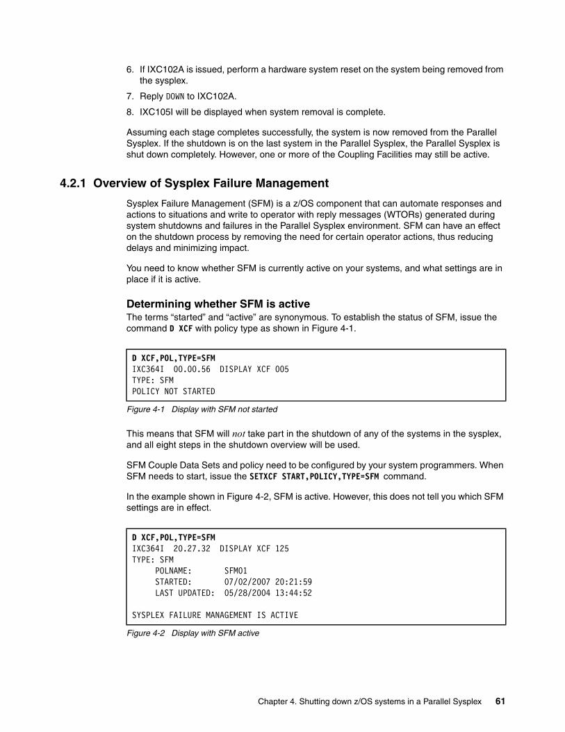
6. If IXC102A is issued, perform a hardware system reset on the system being removed from the sysplex.
7. Reply DOWN to IXC102A.
8. IXC105I will be displayed when system removal is complete.
Assuming each stage completes successfully, the system is now removed from the Parallel Sysplex. If the shutdown is on the last system in the Parallel Sysplex, the Parallel Sysplex is shut down completely. However, one or more of the Coupling Facilities may still be active.
4.2.1 Overview of Sysplex Failure Management
Sysplex Failure Management (SFM) is a z/OS component that can automate responses and actions to situations and write to operator with reply messages (WTORs) generated during system shutdowns and failures in the Parallel Sysplex environment. SFM can have an effect on the shutdown process by removing the need for certain operator actions, thus reducing delays and minimizing impact.
You need to know whether SFM is currently active on your systems, and what settings are in place if it is active.
Determining whether SFM is activeThe terms “started” and “active” are synonymous. To establish the status of SFM, issue the command D XCF with policy type as shown in Figure 4-1.
Figure 4-1 Display with SFM not started
This means that SFM will not take part in the shutdown of any of the systems in the sysplex, and all eight steps in the shutdown overview will be used.
SFM Couple Data Sets and policy need to be configured by your system programmers. When SFM needs to start, issue the SETXCF START,POLICY,TYPE=SFM command.
In the example shown in Figure 4-2, SFM is active. However, this does not tell you which SFM settings are in effect.
Figure 4-2 Display with SFM active
D XCF,POL,TYPE=SFM IXC364I 00.00.56 DISPLAY XCF 005 TYPE: SFM POLICY NOT STARTED
D XCF,POL,TYPE=SFM IXC364I 20.27.32 DISPLAY XCF 125 TYPE: SFM POLNAME: SFM01 STARTED: 07/02/2007 20:21:59 LAST UPDATED: 05/28/2004 13:44:52 SYSPLEX FAILURE MANAGEMENT IS ACTIVE
Chapter 4. Shutting down z/OS systems in a Parallel Sysplex 61
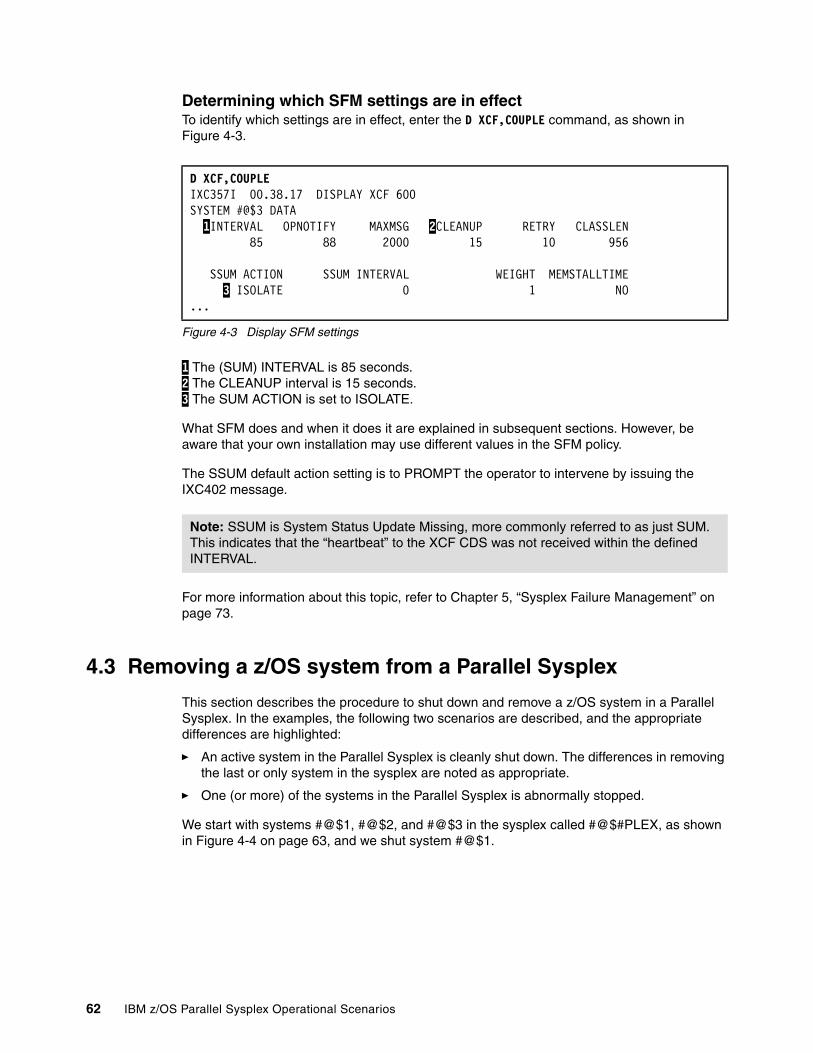
Determining which SFM settings are in effectTo identify which settings are in effect, enter the D XCF,COUPLE command, as shown in Figure 4-3.
Figure 4-3 Display SFM settings
1 The (SUM) INTERVAL is 85 seconds. 2 The CLEANUP interval is 15 seconds. 3 The SUM ACTION is set to ISOLATE.
What SFM does and when it does it are explained in subsequent sections. However, be aware that your own installation may use different values in the SFM policy.
The SSUM default action setting is to PROMPT the operator to intervene by issuing the IXC402 message.
For more information about this topic, refer to Chapter 5, “Sysplex Failure Management” on page 73.
4.3 Removing a z/OS system from a Parallel Sysplex
This section describes the procedure to shut down and remove a z/OS system in a Parallel Sysplex. In the examples, the following two scenarios are described, and the appropriate differences are highlighted:
� An active system in the Parallel Sysplex is cleanly shut down. The differences in removing the last or only system in the sysplex are noted as appropriate.
� One (or more) of the systems in the Parallel Sysplex is abnormally stopped.
We start with systems #@$1, #@$2, and #@$3 in the sysplex called #@$#PLEX, as shown in Figure 4-4 on page 63, and we shut system #@$1.
D XCF,COUPLE IXC357I 00.38.17 DISPLAY XCF 600 SYSTEM #@$3 DATA 1INTERVAL OPNOTIFY MAXMSG 2CLEANUP RETRY CLASSLEN 85 88 2000 15 10 956 SSUM ACTION SSUM INTERVAL WEIGHT MEMSTALLTIME 3 ISOLATE 0 1 NO...
Note: SSUM is System Status Update Missing, more commonly referred to as just SUM. This indicates that the “heartbeat” to the XCF CDS was not received within the defined INTERVAL.
62 IBM z/OS Parallel Sysplex Operational Scenarios

Figure 4-4 Display currently active systems
4.3.1 Procedure for a planned shutdown
This section demonstrates the planned shutdown of a system in a Parallel Sysplex. It continues from the closure of all subsystems as listed in steps 1, step 2, and step 3 in 4.2, “Shutdown overview” on page 60. The amount of shutdown that the operator performs depends on the automation environment installed. However, the actions and their results remain the same.
z/OS closureWhen all the subsystems and applications have been shut down, the response to the D A,L command should be similar to the one shown in Figure 4-5. However, this may not be the case if there were problems during subsystem closure, or due to your site’s configuration.
Figure 4-5 Display for D A,L
To close z/OS cleanly, the operator should issue the end of day command, Z EOD, as shown in Figure 4-6, prior to removing the system from the Parallel Sysplex. This writes a logrec dataset error record, and closes the current SMF dataset to preserve statistical data.
Figure 4-6 Z EOD command
Sysplex partitioningUse the V XCF,sysname,OFFLINE command to remove the closing system from the Parallel Sysplex. This is shown in Figure 4-7 on page 64. It can be issued on any system in the sysplex, including on the system that is being removed.
D XCF,S,ALL IXC335I 19.00.10 DISPLAY XCF 491 SYSTEM TYPE SERIAL LPAR STATUS TIME SYSTEM STATUS #@$3 2084 6A3A N/A 06/21/2007 19:00:10 ACTIVE TM=SIMETR #@$2 2084 6A3A N/A 06/21/2007 19:00:06 ACTIVE TM=SIMETR #@$1 2084 6A3A N/A 06/21/2007 19:00:07 ACTIVE TM=SIMETR
D A,L IEE114I 19.11.42 2007.177 ACTIVITY 412 JOBS M/S TS USERS SYSAS INITS ACTIVE/MAX VTAM OAS 00000 00000 00000 00032 00015 00000/00030 00001
Z EOD IEE334I HALT EOD SUCCESSFUL
Note: The VARY command (and sysname) should still be used when removing the last or only system from the sysplex, because there is still some cleanup to be done. However, you do not receive message IXC102A, because there is no active system to issue it.
Chapter 4. Shutting down z/OS systems in a Parallel Sysplex 63
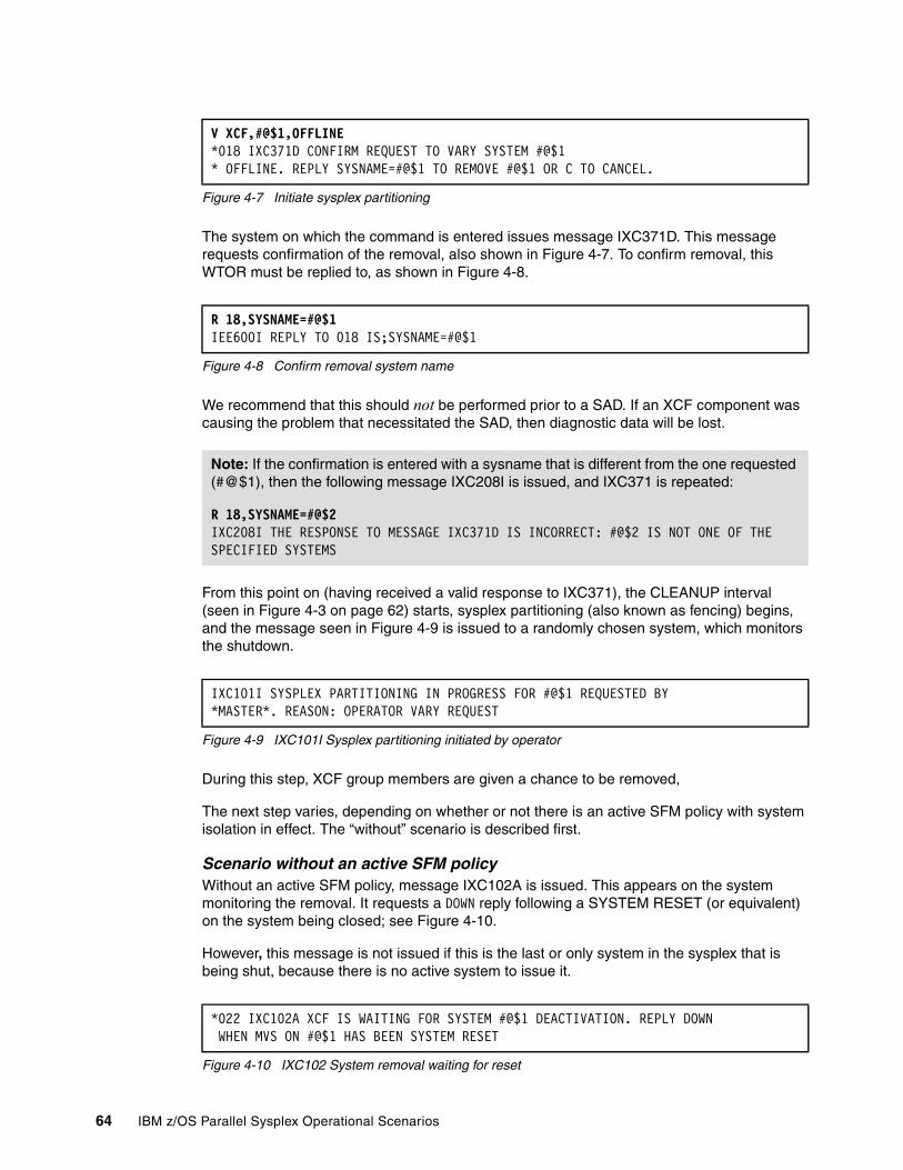
Figure 4-7 Initiate sysplex partitioning
The system on which the command is entered issues message IXC371D. This message requests confirmation of the removal, also shown in Figure 4-7. To confirm removal, this WTOR must be replied to, as shown in Figure 4-8.
Figure 4-8 Confirm removal system name
We recommend that this should not be performed prior to a SAD. If an XCF component was causing the problem that necessitated the SAD, then diagnostic data will be lost.
From this point on (having received a valid response to IXC371), the CLEANUP interval (seen in Figure 4-3 on page 62) starts, sysplex partitioning (also known as fencing) begins, and the message seen in Figure 4-9 is issued to a randomly chosen system, which monitors the shutdown.
Figure 4-9 IXC101I Sysplex partitioning initiated by operator
During this step, XCF group members are given a chance to be removed,
The next step varies, depending on whether or not there is an active SFM policy with system isolation in effect. The “without” scenario is described first.
Scenario without an active SFM policyWithout an active SFM policy, message IXC102A is issued. This appears on the system monitoring the removal. It requests a DOWN reply following a SYSTEM RESET (or equivalent) on the system being closed; see Figure 4-10.
However, this message is not issued if this is the last or only system in the sysplex that is being shut, because there is no active system to issue it.
Figure 4-10 IXC102 System removal waiting for reset
V XCF,#@$1,OFFLINE*018 IXC371D CONFIRM REQUEST TO VARY SYSTEM #@$1 * OFFLINE. REPLY SYSNAME=#@$1 TO REMOVE #@$1 OR C TO CANCEL.
R 18,SYSNAME=#@$1 IEE600I REPLY TO 018 IS;SYSNAME=#@$1
Note: If the confirmation is entered with a sysname that is different from the one requested (#@$1), then the following message IXC208I is issued, and IXC371 is repeated:
R 18,SYSNAME=#@$2IXC208I THE RESPONSE TO MESSAGE IXC371D IS INCORRECT: #@$2 IS NOT ONE OF THE SPECIFIED SYSTEMS
IXC101I SYSPLEX PARTITIONING IN PROGRESS FOR #@$1 REQUESTED BY*MASTER*. REASON: OPERATOR VARY REQUEST
*022 IXC102A XCF IS WAITING FOR SYSTEM #@$1 DEACTIVATION. REPLY DOWN WHEN MVS ON #@$1 HAS BEEN SYSTEM RESET
64 IBM z/OS Parallel Sysplex Operational Scenarios
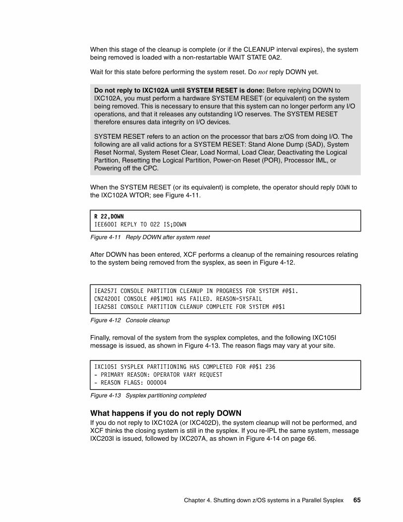
When this stage of the cleanup is complete (or if the CLEANUP interval expires), the system being removed is loaded with a non-restartable WAIT STATE 0A2.
Wait for this state before performing the system reset. Do not reply DOWN yet.
When the SYSTEM RESET (or its equivalent) is complete, the operator should reply DOWN to the IXC102A WTOR; see Figure 4-11.
Figure 4-11 Reply DOWN after system reset
After DOWN has been entered, XCF performs a cleanup of the remaining resources relating to the system being removed from the sysplex, as seen in Figure 4-12.
Figure 4-12 Console cleanup
Finally, removal of the system from the sysplex completes, and the following IXC105I message is issued, as shown in Figure 4-13. The reason flags may vary at your site.
Figure 4-13 Sysplex partitioning completed
What happens if you do not reply DOWNIf you do not reply to IXC102A (or IXC402D), the system cleanup will not be performed, and XCF thinks the closing system is still in the sysplex. If you re-IPL the same system, message IXC203I is issued, followed by IXC207A, as shown in Figure 4-14 on page 66.
Do not reply to IXC102A until SYSTEM RESET is done: Before replying DOWN to IXC102A, you must perform a hardware SYSTEM RESET (or equivalent) on the system being removed. This is necessary to ensure that this system can no longer perform any I/O operations, and that it releases any outstanding I/O reserves. The SYSTEM RESET therefore ensures data integrity on I/O devices.
SYSTEM RESET refers to an action on the processor that bars z/OS from doing I/O. The following are all valid actions for a SYSTEM RESET: Stand Alone Dump (SAD), System Reset Normal, System Reset Clear, Load Normal, Load Clear, Deactivating the Logical Partition, Resetting the Logical Partition, Power-on Reset (POR), Processor IML, or Powering off the CPC.
R 22,DOWN IEE600I REPLY TO 022 IS;DOWN
IEA257I CONSOLE PARTITION CLEANUP IN PROGRESS FOR SYSTEM #@$1.CNZ4200I CONSOLE #@$1M01 HAS FAILED. REASON=SYSFAIL IEA258I CONSOLE PARTITION CLEANUP COMPLETE FOR SYSTEM #@$1
IXC105I SYSPLEX PARTITIONING HAS COMPLETED FOR #@$1 236- PRIMARY REASON: OPERATOR VARY REQUEST - REASON FLAGS: 000004
Chapter 4. Shutting down z/OS systems in a Parallel Sysplex 65

Figure 4-14 IXC203 system currently active
Check for the IXC102A message and reply DOWN to it. When IXC105I is issued, then reply with your correct COUPLExx member and the IPL will continue. You can also choose to start the IPL again.
Scenario with an active SFM policyIn this example, SFM is active and system ISOLATE is coded, as shown in Figure 4-3 on page 62.
Up to this point, the operator had issued V XCFTh and replied with sysname. After IXC101I is issued, SFM waits for the CLEANUP interval to expire, then initiates removal of the closing system. This produces messages including IXC467I, IXC307I, and IXC302I, as shown in Figure 4-16 on page 67.
When system isolation successfully completes, message IXC105 is issued (see Figure 4-13 on page 65), and the system is placed into a disabled WAIT STATE. Refer to “Wait state X'0A2'” on page 66 for more information about this topic.
It is not necessary after successful SFM partitioning to perform a system reset, because the isolated system can no longer perform any I/O.
If SFM isolation is unsuccessfulA failed attempt at fencing could occur for any number of reasons. It is detected by SFM and message IXC102A is issued. As shown in Figure 4-10 on page 64, this requires:
� The closing system to be SYSTEM RESET� The reply of DOWN
As usual, IXC105 is issued when isolation is complete.
Last or only system in the sysplexAs noted previously, the V XCF and reply sysname should still be performed on the last or only system in the sysplex. However, message IXC102A will not be issued. You cannot reply DOWN. Instead, you:
� Observe the 0A2 Wait State� Perform system reset
Completion of removal is flagged by the reset; message IXC105I is not issued because there is no active system to issue it.
Wait state X'0A2'If cleanup processing completes before a SYSTEM RESET is performed, or when an active SFM policy has isolated the system successfully, the system being removed will be placed in a X'0A2' non-restartable wait state. The console clears, and message IXC220W is issued.
IXC203I #@$1 IS CURRENTLY ACTIVE IN THE SYSPLEX IXC218I SYSTEM STATUS FOR SYSPLEX #@$#PLEX AT 06/27/2007 00:54:56: #@$2 00:54:54 ACTIVE #@$1 00:52:11 BEING REMOVED IXC214I COUPLE00 IS THE CURRENT COUPLE PARMLIB MEMBER IXC240I IF XCF-LOCAL MODE INITIALIZATION IS DESIRED, RE-IPL WITH "PLEXCFG=XCFLOCAL" AND "COUPLE=**" IXC207A XCF INITIALIZATION IS RESTARTED. RESPECIFY COUPLE SYSTEM PARAMETER, REPLY COUPLE=XX.
66 IBM z/OS Parallel Sysplex Operational Scenarios

Figure 4-15 0A2 non-restartable wait state
Sysplex cleanupWith any closure of a system in a Parallel Sysplex, whether controlled or not, the remaining systems clean up the XCF connections. This activity occurs when the CLEANUP interval (as shown in Figure 4-3 on page 62) expires.
The default XCF CLEANUP time is sixty seconds. However, thirty seconds is recommended.
As shown in Figure 4-16, GRS and system partitioning take place, and these are indicated by many IXC467I, IXC307I, and IXC302I messages, which may not be seen at the console.
Figure 4-16 PATHIN and PATHOUT cleanup
Checking that the system has been removedIf at least one system is left in the sysplex, reissue the D XCF,S,ALL command to verify that the target system has been removed.
*IXC220W XCF IS UNABLE TO CONTINUE: WAIT STATE CODE: 0A2 REASON CODE: 004, AN OPERATOR REQUESTED PARTITIONING WITH THE VARY XCF COMMAND
Important: Wait for the WAIT STATE before performing SYSTEM RESET.
Tip: Set XCF CLEANUP interval to 30 seconds.
IXC467I STOPPING PATH STRUCTURE IXC_DEFAULT_2 217 RSN: SYSPLEX PARTITIONING OF LOCAL SYSTEM IXC467I STOPPING PATHOUT STRUCTURE IXC_DEFAULT_2 LIST 8 218 USED TO COMMUNICATE WITH SYSTEM #@$2 RSN: SYSPLEX PARTITIONING OF LOCAL SYSTEM ...IXC307I STOP PATHOUT REQUEST FOR STRUCTURE IXC_DEFAULT_2 226 LIST 10 TO COMMUNICATE WITH SYSTEM #@$3 COMPLETED SUCCESSFULLY: SYSPLEX PARTITIONING OF LOCAL SYSTEM IXC307I STOP PATHOUT REQUEST FOR STRUCTURE IXC_DEFAULT_2 224 LIST 8 TO COMMUNICATE WITH SYSTEM #@$2 COMPLETED SUCCESSFULLY: SYSPLEX PARTITIONING OF LOCAL SYSTEM ...IXC302I STOP PATHIN REQUEST FOR STRUCTURE IXC_DEFAULT_1 116 LIST 0 TO COMMUNICATE WITH SYSTEM #@$1 REJECTED: UNKNOWN PATH DIAG037=18 DIAG074=08710000 RC,RSN=00000008 081A0004 IXC302I STOP PATHIN REQUEST FOR STRUCTURE IXC_DEFAULT_2 117 LIST 0 TO COMMUNICATE WITH SYSTEM #@$1 REJECTED: UNKNOWN PATH DIAG037=18 DIAG074=08710000 RC,RSN=00000008 081A0004
Chapter 4. Shutting down z/OS systems in a Parallel Sysplex 67
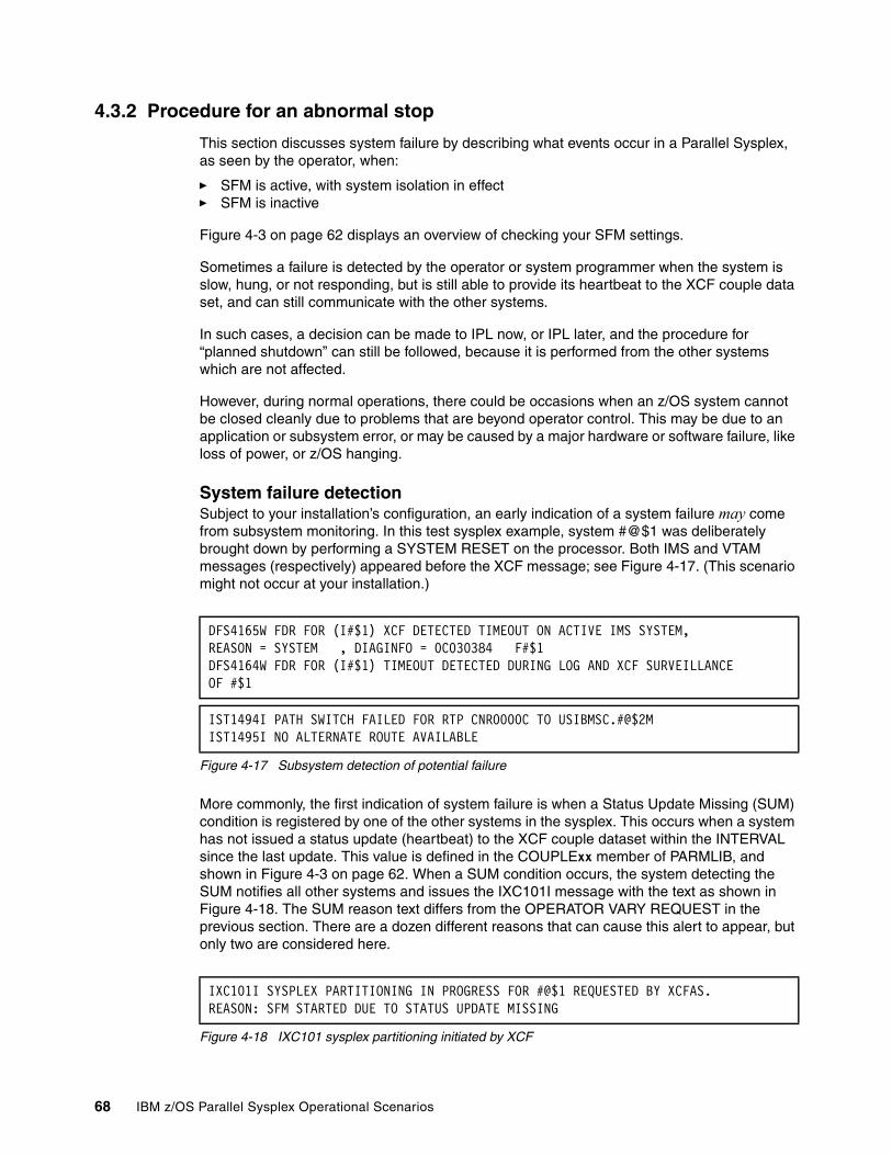
4.3.2 Procedure for an abnormal stop
This section discusses system failure by describing what events occur in a Parallel Sysplex, as seen by the operator, when:
� SFM is active, with system isolation in effect� SFM is inactive
Figure 4-3 on page 62 displays an overview of checking your SFM settings.
Sometimes a failure is detected by the operator or system programmer when the system is slow, hung, or not responding, but is still able to provide its heartbeat to the XCF couple data set, and can still communicate with the other systems.
In such cases, a decision can be made to IPL now, or IPL later, and the procedure for “planned shutdown” can still be followed, because it is performed from the other systems which are not affected.
However, during normal operations, there could be occasions when an z/OS system cannot be closed cleanly due to problems that are beyond operator control. This may be due to an application or subsystem error, or may be caused by a major hardware or software failure, like loss of power, or z/OS hanging.
System failure detectionSubject to your installation’s configuration, an early indication of a system failure may come from subsystem monitoring. In this test sysplex example, system #@$1 was deliberately brought down by performing a SYSTEM RESET on the processor. Both IMS and VTAM messages (respectively) appeared before the XCF message; see Figure 4-17. (This scenario might not occur at your installation.)
Figure 4-17 Subsystem detection of potential failure
More commonly, the first indication of system failure is when a Status Update Missing (SUM) condition is registered by one of the other systems in the sysplex. This occurs when a system has not issued a status update (heartbeat) to the XCF couple dataset within the INTERVAL since the last update. This value is defined in the COUPLExx member of PARMLIB, and shown in Figure 4-3 on page 62. When a SUM condition occurs, the system detecting the SUM notifies all other systems and issues the IXC101I message with the text as shown in Figure 4-18. The SUM reason text differs from the OPERATOR VARY REQUEST in the previous section. There are a dozen different reasons that can cause this alert to appear, but only two are considered here.
Figure 4-18 IXC101 sysplex partitioning initiated by XCF
DFS4165W FDR FOR (I#$1) XCF DETECTED TIMEOUT ON ACTIVE IMS SYSTEM, REASON = SYSTEM , DIAGINFO = 0C030384 F#$1 DFS4164W FDR FOR (I#$1) TIMEOUT DETECTED DURING LOG AND XCF SURVEILLANCEOF #$1
IST1494I PATH SWITCH FAILED FOR RTP CNR0000C TO USIBMSC.#@$2MIST1495I NO ALTERNATE ROUTE AVAILABLE
IXC101I SYSPLEX PARTITIONING IN PROGRESS FOR #@$1 REQUESTED BY XCFAS.REASON: SFM STARTED DUE TO STATUS UPDATE MISSING
68 IBM z/OS Parallel Sysplex Operational Scenarios
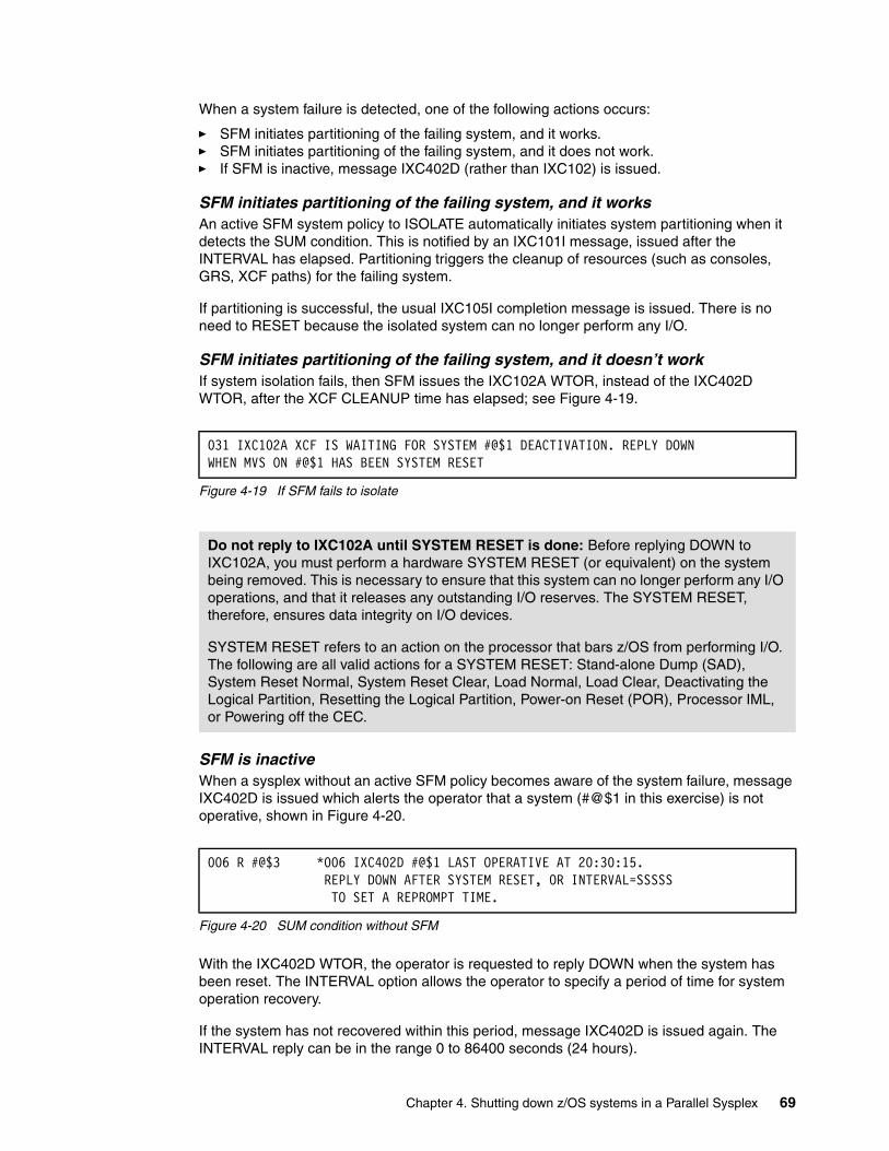
When a system failure is detected, one of the following actions occurs:
� SFM initiates partitioning of the failing system, and it works.� SFM initiates partitioning of the failing system, and it does not work.� If SFM is inactive, message IXC402D (rather than IXC102) is issued.
SFM initiates partitioning of the failing system, and it worksAn active SFM system policy to ISOLATE automatically initiates system partitioning when it detects the SUM condition. This is notified by an IXC101I message, issued after the INTERVAL has elapsed. Partitioning triggers the cleanup of resources (such as consoles, GRS, XCF paths) for the failing system.
If partitioning is successful, the usual IXC105I completion message is issued. There is no need to RESET because the isolated system can no longer perform any I/O.
SFM initiates partitioning of the failing system, and it doesn’t workIf system isolation fails, then SFM issues the IXC102A WTOR, instead of the IXC402D WTOR, after the XCF CLEANUP time has elapsed; see Figure 4-19.
Figure 4-19 If SFM fails to isolate
SFM is inactiveWhen a sysplex without an active SFM policy becomes aware of the system failure, message IXC402D is issued which alerts the operator that a system (#@$1 in this exercise) is not operative, shown in Figure 4-20.
Figure 4-20 SUM condition without SFM
With the IXC402D WTOR, the operator is requested to reply DOWN when the system has been reset. The INTERVAL option allows the operator to specify a period of time for system operation recovery.
If the system has not recovered within this period, message IXC402D is issued again. The INTERVAL reply can be in the range 0 to 86400 seconds (24 hours).
031 IXC102A XCF IS WAITING FOR SYSTEM #@$1 DEACTIVATION. REPLY DOWN WHEN MVS ON #@$1 HAS BEEN SYSTEM RESET
Do not reply to IXC102A until SYSTEM RESET is done: Before replying DOWN to IXC102A, you must perform a hardware SYSTEM RESET (or equivalent) on the system being removed. This is necessary to ensure that this system can no longer perform any I/O operations, and that it releases any outstanding I/O reserves. The SYSTEM RESET, therefore, ensures data integrity on I/O devices.
SYSTEM RESET refers to an action on the processor that bars z/OS from performing I/O. The following are all valid actions for a SYSTEM RESET: Stand-alone Dump (SAD), System Reset Normal, System Reset Clear, Load Normal, Load Clear, Deactivating the Logical Partition, Resetting the Logical Partition, Power-on Reset (POR), Processor IML, or Powering off the CEC.
006 R #@$3 *006 IXC402D #@$1 LAST OPERATIVE AT 20:30:15. REPLY DOWN AFTER SYSTEM RESET, OR INTERVAL=SSSSS TO SET A REPROMPT TIME.
Chapter 4. Shutting down z/OS systems in a Parallel Sysplex 69

After the SYSTEM RESET has been performed, you can reply DOWN to IXC402D, as shown in Figure 4-21. It is only this reply that starts the partitioning.
Figure 4-21 DOWN reply after IXC402
SFM without isolationThere is another possible but unusual scenario, which is to have an active SFM policy that specifies PROMPT (which is the default) instead of ISOLATE. Although it may seem to defeat the purpose of SFM to have it prompt, it is nonetheless possible. When SFM is prompted during an SUM condition (it is not invoked during normal shutdown), it issues the IXC402D message. Actions are thus the same as for “SFM is inactive” on page 69.
System cleanupNo matter how it is arrived at, after the DOWN reply, XCF performs a cleanup of resources relating to the system being removed. This activity starts and ends with the IEA257I and IEA258I messages interspersed with IEE501I messages, as shown in Figure 4-22.
Figure 4-22 Console cleanup
When system removal completes, IXC105I message is issued. The system is now out of the sysplex, as shown in Figure 4-23.
Figure 4-23 Sysplex partitioning completed
Sysplex cleanupWith any closure of a system in a Parallel Sysplex (except the last or only), whether controlled or not, the remaining systems clean up the XCF connections. This activity occurs at the same time as GRS and system partitioning take place. This is indicated by many IXC302 1, IXC307I 2, and IXC467I 3 messages, which may not be seen at the console; see Figure 4-24 on page 71.
R 06,DOWN IEE600I REPLY TO 006 IS;DOWN
Important: As for an IXC102A message, with IXC402D do not reply DOWN until a SYSTEM RESET has been performed.
IEA257I CONSOLE PARTITION CLEANUP IN PROGRESS FOR SYSTEM #@$1.CNZ4200I CONSOLE #@$1M01 HAS FAILED. REASON=SYSFAIL IEA258I CONSOLE PARTITION CLEANUP COMPLETE FOR SYSTEM #@$1IEE501I CONSOLE #@$1M01 FAILED, REASON=SFAIL . ALL ALTERNATESUNAVAILABLE, CONSOLE IS NOT SWITCHED
Note: When you receive message IXC105I, the RSN text may be different.
IXC105I SYSPLEX PARTITIONING HAS COMPLETED FOR #@$1 790 - PRIMARY REASON: SYSTEM REMOVED BY SYSPLEX FAILURE MANAGEMENT BECAUSE ITS STATUS UPDATE WAS MISSING - REASON FLAGS: 000100
70 IBM z/OS Parallel Sysplex Operational Scenarios
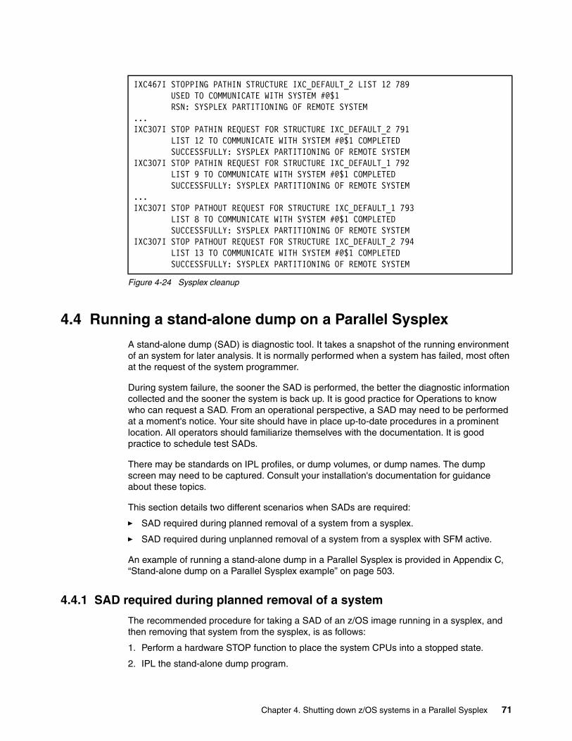
Figure 4-24 Sysplex cleanup
4.4 Running a stand-alone dump on a Parallel Sysplex
A stand-alone dump (SAD) is diagnostic tool. It takes a snapshot of the running environment of an system for later analysis. It is normally performed when a system has failed, most often at the request of the system programmer.
During system failure, the sooner the SAD is performed, the better the diagnostic information collected and the sooner the system is back up. It is good practice for Operations to know who can request a SAD. From an operational perspective, a SAD may need to be performed at a moment's notice. Your site should have in place up-to-date procedures in a prominent location. All operators should familiarize themselves with the documentation. It is good practice to schedule test SADs.
There may be standards on IPL profiles, or dump volumes, or dump names. The dump screen may need to be captured. Consult your installation's documentation for guidance about these topics.
This section details two different scenarios when SADs are required:
� SAD required during planned removal of a system from a sysplex.
� SAD required during unplanned removal of a system from a sysplex with SFM active.
An example of running a stand-alone dump in a Parallel Sysplex is provided in Appendix C, “Stand-alone dump on a Parallel Sysplex example” on page 503.
4.4.1 SAD required during planned removal of a system
The recommended procedure for taking a SAD of an z/OS image running in a sysplex, and then removing that system from the sysplex, is as follows:
1. Perform a hardware STOP function to place the system CPUs into a stopped state.
2. IPL the stand-alone dump program.
IXC467I STOPPING PATHIN STRUCTURE IXC_DEFAULT_2 LIST 12 789 USED TO COMMUNICATE WITH SYSTEM #@$1 RSN: SYSPLEX PARTITIONING OF REMOTE SYSTEM ... IXC307I STOP PATHIN REQUEST FOR STRUCTURE IXC_DEFAULT_2 791 LIST 12 TO COMMUNICATE WITH SYSTEM #@$1 COMPLETED SUCCESSFULLY: SYSPLEX PARTITIONING OF REMOTE SYSTEM IXC307I STOP PATHIN REQUEST FOR STRUCTURE IXC_DEFAULT_1 792 LIST 9 TO COMMUNICATE WITH SYSTEM #@$1 COMPLETED SUCCESSFULLY: SYSPLEX PARTITIONING OF REMOTE SYSTEM ...IXC307I STOP PATHOUT REQUEST FOR STRUCTURE IXC_DEFAULT_1 793 LIST 8 TO COMMUNICATE WITH SYSTEM #@$1 COMPLETED SUCCESSFULLY: SYSPLEX PARTITIONING OF REMOTE SYSTEM IXC307I STOP PATHOUT REQUEST FOR STRUCTURE IXC_DEFAULT_2 794 LIST 13 TO COMMUNICATE WITH SYSTEM #@$1 COMPLETED SUCCESSFULLY: SYSPLEX PARTITIONING OF REMOTE SYSTEM
Chapter 4. Shutting down z/OS systems in a Parallel Sysplex 71

3. Issue the VARY XCF,sysname,OFFLINE command from another system in the sysplex (if message IXC402D or IXC102A is not already present).
4. Reply DOWN to message IXC402D or IXC102A, without performing a SYSTEM RESET, because this has already taken place through the IPL of the SADMP program, and you would cause the SADMP to fail.
Note the following points:
� If this is the last or only system in the sysplex, then step 1 and step 2 apply.
� If the system has already been removed from the sysplex, then only step 2 applies.
� You do not need to wait for the SAD to complete before continuing with step 3.
� Performing steps 3 and 4 immediately after IPLing the SAD will speed up sysplex recovery, allowing resources held by the IPLing system to be released quickly.
� If there is a delay between steps 2 and 3, then messages IXC402D or IXC102A may be issued by another system detecting the loss of connectivity with the IPLing system.
� After the SAD program is IPLed, IXC402D or IXC102A will be issued, even if an active SFM policy is in effect. This happens because z/OS is unable to automatically partition the failing system using SFM.
4.4.2 SAD required during unplanned removal of a system with SFM active
If SFM is active and system isolation is in effect, then it will detect the system failure and start sysplex partitioning. In this case, follow this procedure:
1. Perform a hardware STOP function to place the failing system’s CPUs into a stopped state (this is not strictly required, but is good practice).
2. IPL the standalone dump program on the failing system,
3. If message IXC102A is present, reply DOWN without performing a SYSTEM RESET.
72 IBM z/OS Parallel Sysplex Operational Scenarios
Chapter 5. Sysplex Failure Management
This chapter provides information about the Sysplex Failure Management (SFM) function. It introduces commands that you can use to determine the status of SFM in your sysplex.
This chapter explains:
� Why to use SFM
� How SFM reacts to various failure situations
� How to control SFM
5
© Copyright IBM Corp. 2009. All rights reserved. 73

5.1 Introduction to Sysplex Failure Management
Sysplex Failure Management (SFM) is an availability function that is integrated into the z/OS base. It allows you to define a sysplex-wide policy that specifies the actions z/OS is to take when certain failures occur in the sysplex, such as when a system loses access to a Coupling Facility.
When SFM is active, it is invoked automatically to minimize the impact that a failing system might have on the workloads running in a sysplex. It does this by automating the recovery actions, which shortens the recovery time and reduces the time the sysplex is impacted by the failure. If these recovery actions are not performed quickly, there may be an extended impact to the other systems and the workloads running on them. For instance, if a system fails while holding an exclusive GRS enqueue, work on the other systems may wait until the enqueue is released before they can continue their processing.
Some sysplex delays may also occur during recovery processing. If a system fails while holding some locks, XES will transfer the management of the locks to one of the other systems during the cleanup processing. During this transition, Cross-System Extended Service (XES) will quiesce all activity to the associated lock structures to preserve data integrity. This delay may impact the subsystems that use these lock structures, such as IRLM/DB2, VSAM RLS and IRLM/IMS.
SFM is invoked for both planned and unplanned conditions, when:
� A system is varied out of the sysplex using the VARY XCF command
� A system enters a Status Update Missing condition
� An XCF signalling connectivity failure occurs
� A system loses connectivity to a Coupling Facility
When a failure is detected, a recovery action is initiated, such as:
� Isolating the failed image
� Deactivating logical partitions
� Reallocating real storage
These recovery actions can be initiated automatically and completed without operator intervention, or a message can be issued, prompting the operator to perform the recovery actions manually. The recovery actions are defined in the SFM policy.
For a sysplex to take advantage of SFM, all systems must have connectivity to the SFM couple datasets and the SFM policy must be started.
For additional information about SFM, see MVS Setting up a Sysplex, SA22-7625.
5.2 Status Update Missing condition
For each z/OS system, XCF updates the sysplex couple dataset (CDS) with its status every few seconds; the status consists of a time stamp and it is sometimes referred to as a “heartbeat”. For example, if you have 10 systems in a sysplex, all 10 systems update their respective heartbeats in the sysplex CDS every few seconds.
In addition to writing the heartbeat time stamps to the sysplex CDS, XCF on each z/OS system monitors the heartbeat time stamps of the other z/OS systems in the sysplex CDS. If
74 IBM z/OS Parallel Sysplex Operational Scenarios
any z/OS system's heartbeat time stamp is older than the current time minus that system's INTERVAL value from the COUPLExx parmlib member, that system is considered to have failed in some way. When this occurs, the failed system is considered to be in a Status Update Missing (SUM) condition. All systems are notified when a SUM condition occurs. The recovery actions which are taken when a SUM condition occurs depend on the recovery parameters that you specify in your SFM policy. They could be:
� Prompt the operator to perform the recovery actions manually.
� Remove the system from the sysplex without operator intervention by:
– Using the Coupling Facility fencing services to isolate the system.
– System resetting the failing system’s LPAR.
– Deactivating the failing system’s LPAR.
5.3 XCF signalling failure
XCF monitors XCF signalling connectivity to ensure that systems in the sysplex can communicate with each other. If XCF detects that two or more systems can no longer communicate with each other because some signalling paths have failed, then SFM will determine which systems should be partitioned out of the sysplex and proceed to remove them from the sysplex in one of two ways:
� Automatically, without operator intervention
� By prompting the operator to perform the recovery actions manually
SFM’s recovery action is controlled by two parameters in your SFM policy:
� WEIGHT
The WEIGHT parameter from the SFM policy allows you to indicate the relative importance of each system in the sysplex. SFM uses this value to determine which systems should be partitioned out of the sysplex when signalling connectivity failures occur.
� CONNFAIL
The CONNFAIL parameter controls SFM’s recovery actions if signalling connectivity fails between one or more systems in the sysplex:
– If you specify YES, then SFM performs sysplex partitioning actions using the WEIGHT values assigned to each system in the sysplex. SFM determines the best set of systems to remain in the sysplex and which systems to remove from the sysplex, and then attempts to implement that decision by system isolation.
– If you specify NO, then SFM prompts the operator to decide which system or systems to partition from the sysplex.
5.4 Loss of connectivity to a Coupling Facility
A Coupling Facility (CF) link failure or certain types of failures within a CF can cause one or more systems to lose connectivity to a CF. This means these systems will also lose connectivity to the structures residing in that CF.
In this situation, z/OS initiates a structure rebuild, which is a facility that allows structures to be rebuilt into another CF. If the structure supports rebuild, it rebuilds into another CF and the structure exploiters connect to it in the new location.
Chapter 5. Sysplex Failure Management 75

If the structure supports rebuild, you can influence when it should be rebuilt by using the REBUILDPERCENT parameter in the structure’s definition in the Coupling Facility Resource Management (CFRM) policy:
� The structure is rebuilt if the weight of the system that lost connectivity is equal to or greater than the REBUILDPERCENT value you specified.
� The structure is not rebuilt if the weight of the system that lost connectivity is less than the REBUILDPERCENT value you specified. In this case, the affected system will go into error handling to recover from the connectivity failure.
If the structure supports user-managed rebuild and you used the default value of 1% for REBUILDPERCENT, the structure rebuilds when a loss of connectivity occurs.
During the rebuild, to ensure that the rebuilt structure has better connectivity to the systems in the sysplex than the old structure, the CF selection process will factor in the SFM system weights and the connectivity that each system has to the CF. However, if there is no SFM policy active, all the systems are treated as having equal weights when determining the suitability of a CF for the new structure allocation.
5.5 PR/SM reconfiguration
After a system running in an LPAR is removed from the sysplex, SFM allows the remaining systems in the sysplex to take the processor storage that had been in use by the failed system and make it available for their own use.
5.6 Sympathy sickness
The Sysplex Failure Management (SFM) function in z/OS is enhanced to support a new policy specification for how long a system should be allowed to remain in the sysplex when it appears unresponsive because it is not updating its system status on the Sysplex Couple Data Set, yet it is still sending XCF signals to other systems in the sysplex. A system that is in this state is definitely not completely inoperable (because it is sending XCF signals), and yet it may not be fully functional either, so it may be causing sysplex sympathy sickness problems for other active systems in the sysplex.
The new SFM policy externally provides a way for installations to limit their exposure to problems caused by such systems, by automatically removing them from the sysplex after a specified period of time. The Sysplex Failure Management (SFM) function in z/OS is enhanced to support a new policy specification to indicate that, after a specified period of time, the system may automatically terminate XCF members that have been identified as stalled and who also appear to be causing sympathy sickness problems.
If allowed to persist, these stalled members can lead to sysplex-wide hangs or other problems, not only within their own XCF group, but also for any other system or application functions that depend on the impacted function. Automatically terminating these members is intended to provide improved application availability within the sysplex.
76 IBM z/OS Parallel Sysplex Operational Scenarios
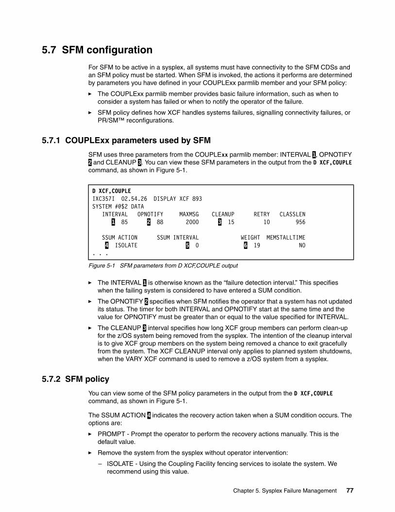
5.7 SFM configuration
For SFM to be active in a sysplex, all systems must have connectivity to the SFM CDSs and an SFM policy must be started. When SFM is invoked, the actions it performs are determined by parameters you have defined in your COUPLExx parmlib member and your SFM policy:
� The COUPLExx parmlib member provides basic failure information, such as when to consider a system has failed or when to notify the operator of the failure.
� SFM policy defines how XCF handles systems failures, signalling connectivity failures, or PR/SM™ reconfigurations.
5.7.1 COUPLExx parameters used by SFM
SFM uses three parameters from the COUPLExx parmlib member: INTERVAL 1, OPNOTIFY 2 and CLEANUP 3. You can view these SFM parameters in the output from the D XCF,COUPLE command, as shown in Figure 5-1.
Figure 5-1 SFM parameters from D XCF,COUPLE output
� The INTERVAL 1 is otherwise known as the “failure detection interval.” This specifies when the failing system is considered to have entered a SUM condition.
� The OPNOTIFY 2 specifies when SFM notifies the operator that a system has not updated its status. The timer for both INTERVAL and OPNOTIFY start at the same time and the value for OPNOTIFY must be greater than or equal to the value specified for INTERVAL.
� The CLEANUP 3 interval specifies how long XCF group members can perform clean-up for the z/OS system being removed from the sysplex. The intention of the cleanup interval is to give XCF group members on the system being removed a chance to exit gracefully from the system. The XCF CLEANUP interval only applies to planned system shutdowns, when the VARY XCF command is used to remove a z/OS system from a sysplex.
5.7.2 SFM policy
You can view some of the SFM policy parameters in the output from the D XCF,COUPLE command, as shown in Figure 5-1.
The SSUM ACTION 4 indicates the recovery action taken when a SUM condition occurs. The options are:
� PROMPT - Prompt the operator to perform the recovery actions manually. This is the default value.
� Remove the system from the sysplex without operator intervention:
– ISOLATE - Using the Coupling Facility fencing services to isolate the system. We recommend using this value.
D XCF,COUPLE IXC357I 02.54.26 DISPLAY XCF 893 SYSTEM #@$2 DATA INTERVAL OPNOTIFY MAXMSG CLEANUP RETRY CLASSLEN 1 85 2 88 2000 3 15 10 956 SSUM ACTION SSUM INTERVAL WEIGHT MEMSTALLTIME 4 ISOLATE 5 0 6 19 NO . . .
Chapter 5. Sysplex Failure Management 77

– RESET - System resetting the failing system’s LPAR.
– DEACTIVATE - Deactivating the failing system’s LPAR.
In this example, the option is ISOLATE, which causes SFM to initiate automatic removal of the failing system from the sysplex using CF fencing services.
The SSUM INTERVAL 5 indicates how soon after the “failure detection interval” expires that the recovery action occurs. In this example, the value is 0. Thus, the failing system will be removed from the sysplex as soon as it enters a SUM condition; 85 seconds after the last status update.
The WEIGHT 6 is used if signalling connectivity errors occur:
� The WEIGHT parameter allows you to indicate the relative importance of each system in the sysplex. SFM uses this value to determine which systems should be partitioned out of the sysplex if a signalling connectivity failure occurs. This can be a value between 1 and 9999.
� SFM determines whether to initiate a rebuild for a structure in a Coupling Facility to which a system has lost connectivity. SMF uses the assigned weights in conjunction with the REBUILDPERCENT value specified in the CFRM policy.
The policy information also specifies whether SFM is used to automatically recover XCF signaling connectivity failures and what reconfiguration actions are to be taken when the PR/SM Automatic Reconfiguration Facility is being used. These options cannot be displayed via an operator command; however, the contents of the active SFM policy can be listed using a batch job.
The sample JCL for this batch job is shown in Figure 5-2. Consult your system programmer before running this job to ensure you have the correct security access.
Figure 5-2 SFM policy report sample JCL
5.7.3 Access to the SFM CDSs
For SFM to be active in the sysplex, all systems must have connectivity to the SFM CDSs and the SFM policy must be started. If any system loses connectivity to both the primary and alternate SFM CDS, SFM becomes inactive in the sysplex. SFM automatically becomes active again when all systems regain access to either the primary or alternate SFM CDS.
//DEFSFMP1 JOB (0,0),'SFM POLICY',CLASS=A,MSGCLASS=X, // NOTIFY=&SYSUID //*JOBPARM SYSAFF=#@$3 //*****************************************************//STEP10 EXEC PGM=IXCMIAPU //STEPLIB DD DSN=SYS1.MIGLIB,DISP=SHR //SYSPRINT DD SYSOUT=* //SYSIN DD * DATA TYPE(SFM) REPORT(YES) /*
78 IBM z/OS Parallel Sysplex Operational Scenarios
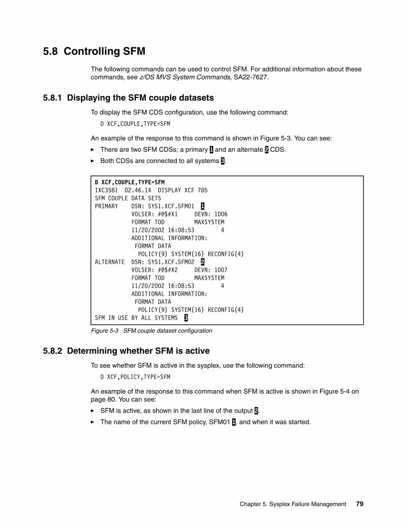
5.8 Controlling SFM
The following commands can be used to control SFM. For additional information about these commands, see z/OS MVS System Commands, SA22-7627.
5.8.1 Displaying the SFM couple datasets
To display the SFM CDS configuration, use the following command:
D XCF,COUPLE,TYPE=SFM
An example of the response to this command is shown in Figure 5-3. You can see:
� There are two SFM CDSs; a primary 1 and an alternate 2 CDS.
� Both CDSs are connected to all systems 3.
Figure 5-3 SFM couple dataset configuration
5.8.2 Determining whether SFM is active
To see whether SFM is active in the sysplex, use the following command:
D XCF,POLICY,TYPE=SFM
An example of the response to this command when SFM is active is shown in Figure 5-4 on page 80. You can see:
� SFM is active, as shown in the last line of the output 2.
� The name of the current SFM policy, SFM01 1, and when it was started.
D XCF,COUPLE,TYPE=SFM IXC358I 02.46.14 DISPLAY XCF 785 SFM COUPLE DATA SETS PRIMARY DSN: SYS1.XCF.SFM01 1 VOLSER: #@$#X1 DEVN: 1D06 FORMAT TOD MAXSYSTEM 11/20/2002 16:08:53 4 ADDITIONAL INFORMATION: FORMAT DATA POLICY(9) SYSTEM(16) RECONFIG(4) ALTERNATE DSN: SYS1.XCF.SFM02 2 VOLSER: #@$#X2 DEVN: 1D07 FORMAT TOD MAXSYSTEM 11/20/2002 16:08:53 4 ADDITIONAL INFORMATION: FORMAT DATA POLICY(9) SYSTEM(16) RECONFIG(4) SFM IN USE BY ALL SYSTEMS 3
Chapter 5. Sysplex Failure Management 79
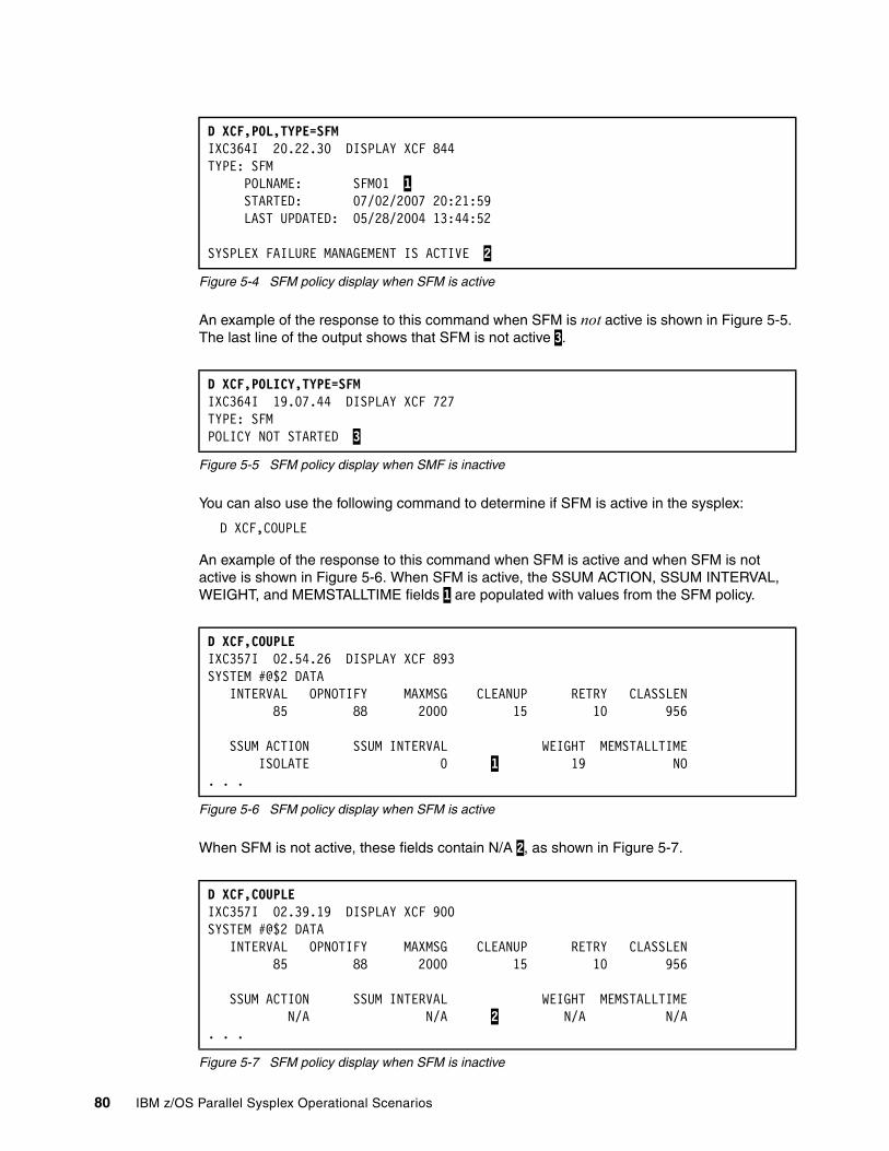
Figure 5-4 SFM policy display when SFM is active
An example of the response to this command when SFM is not active is shown in Figure 5-5. The last line of the output shows that SFM is not active 3.
Figure 5-5 SFM policy display when SMF is inactive
You can also use the following command to determine if SFM is active in the sysplex:
D XCF,COUPLE
An example of the response to this command when SFM is active and when SFM is not active is shown in Figure 5-6. When SFM is active, the SSUM ACTION, SSUM INTERVAL, WEIGHT, and MEMSTALLTIME fields 1 are populated with values from the SFM policy.
Figure 5-6 SFM policy display when SFM is active
When SFM is not active, these fields contain N/A 2, as shown in Figure 5-7.
Figure 5-7 SFM policy display when SFM is inactive
D XCF,POL,TYPE=SFM IXC364I 20.22.30 DISPLAY XCF 844 TYPE: SFM POLNAME: SFM01 1 STARTED: 07/02/2007 20:21:59 LAST UPDATED: 05/28/2004 13:44:52 SYSPLEX FAILURE MANAGEMENT IS ACTIVE 2
D XCF,POLICY,TYPE=SFM IXC364I 19.07.44 DISPLAY XCF 727 TYPE: SFM POLICY NOT STARTED 3
D XCF,COUPLE IXC357I 02.54.26 DISPLAY XCF 893 SYSTEM #@$2 DATA INTERVAL OPNOTIFY MAXMSG CLEANUP RETRY CLASSLEN 85 88 2000 15 10 956 SSUM ACTION SSUM INTERVAL WEIGHT MEMSTALLTIME ISOLATE 0 1 19 NO . . .
D XCF,COUPLE IXC357I 02.39.19 DISPLAY XCF 900 SYSTEM #@$2 DATA INTERVAL OPNOTIFY MAXMSG CLEANUP RETRY CLASSLEN 85 88 2000 15 10 956 SSUM ACTION SSUM INTERVAL WEIGHT MEMSTALLTIME N/A N/A 2 N/A N/A . . .
80 IBM z/OS Parallel Sysplex Operational Scenarios

5.8.3 Starting and stopping the SFM policy
To start an SFM policy, use the following command. In this example we are starting an SFM policy called SFM01:
SETXCF START,POLICY,TYPE=SFM,POLNAME=SFM01
An example of the system response to this command is shown in Figure 5-8. The system responses show which SFM values were taken from the SFM policy 1 and 2, and which values are system defaults 3.
Figure 5-8 Console messages when starting SFM policy
If your system programmer asks you to stop the current SFM policy, use the following command:
SETXCF STOP,POLICY,TYPE=SFM
An example of the system response to this command is shown in Figure 5-9. This command stops the SFM policy on all systems in the sysplex. After the SFM policy is stopped, its status in the sysplex changes to POLICY NOT STARTED, as shown in Figure 5-5 on page 80.
Figure 5-9 Console messages when stopping SFM policy
5.8.4 Replacing the primary SFM CDS
The process to replace a primary CDS is described in Chapter 8, “Couple Data Set management” on page 165.
5.8.5 Shutting down systems when SFM is active
The process to shut down a system when SFM is active is described in Chapter 4, “Shutting down z/OS systems in a Parallel Sysplex” on page 59.
SFM isolation failureWhen SFM does not successfully isolate the system being removed, you have to perform the recovery actions manually.
There are several reasons why SFM may not isolate the system being removed, such as:
� There is no CF in the configuration.
� A system-to-CF link is inoperative or not configured.
SETXCF START,POLICY,TYPE=SFM,POLNAME=SFM01 IXC602I SFM POLICY SFM01 INDICATES FOR SYSTEM #@$2 A STATUS 838 UPDATE MISSING ACTION OF ISOLATE AND AN INTERVAL OF 0 SECONDS. THE ACTION WAS SPECIFIED FOR THIS SYSTEM. 1 IXC609I SFM POLICY SFM01 INDICATES FOR SYSTEM #@$2 A SYSTEM WEIGHT OF 19 SPECIFIED BY SPECIFIC POLICY ENTRY 2 IXC614I SFM POLICY SFM01 INDICATES MEMSTALLTIME(NO) FOR SYSTEM #@$2 AS SPECIFIED BY SYSTEM DEFAULT 3 IXC601I SFM POLICY SFM01 HAS BEEN STARTED BY SYSTEM #@$2
SETXCF STOP,POLICY,TYPE=SFM IXC607I SFM POLICY HAS BEEN STOPPED BY SYSTEM #@$2
Chapter 5. Sysplex Failure Management 81

� The system being removed was SYSTEM RESET or IPLed.
� The logical partition where the system being removed resides was deactivated.
If SFM is unable to isolate the system being removed, it will issue the message IXC102A when the XCF CLEANUP interval expires, as shown in Figure 5-10.
Figure 5-10 IXC102A message
When you receive message IXC102A, perform the following:
� A SYSTEM RESET on the z/OS system being removed from the sysplex, if you have not already done so.
� Reply DOWN to IXC102A.
Message IXC105I will be issued when system removal is complete.
IXC102A XCF IS WAITING FOR SYSTEM #@$1 DEACTIVATION. REPLY DOWN WHEN MVS ON #@$1 HAS BEEN SYSTEM RESET
82 IBM z/OS Parallel Sysplex Operational Scenarios
Chapter 6. Automatic Restart Manager
This chapter discusses Automatic Restart Manager (ARM) scenarios. It also examines problems that may be encountered with ARM policies.
� How to define an ARM policy
� What happens during an ARM restart
Finally, the chapter provides an example that illustrates how to define a simple task to ARM; see 6.5, “Defining SDSF as a new ARM element” on page 91.
6
© Copyright IBM Corp. 2009. All rights reserved. 83
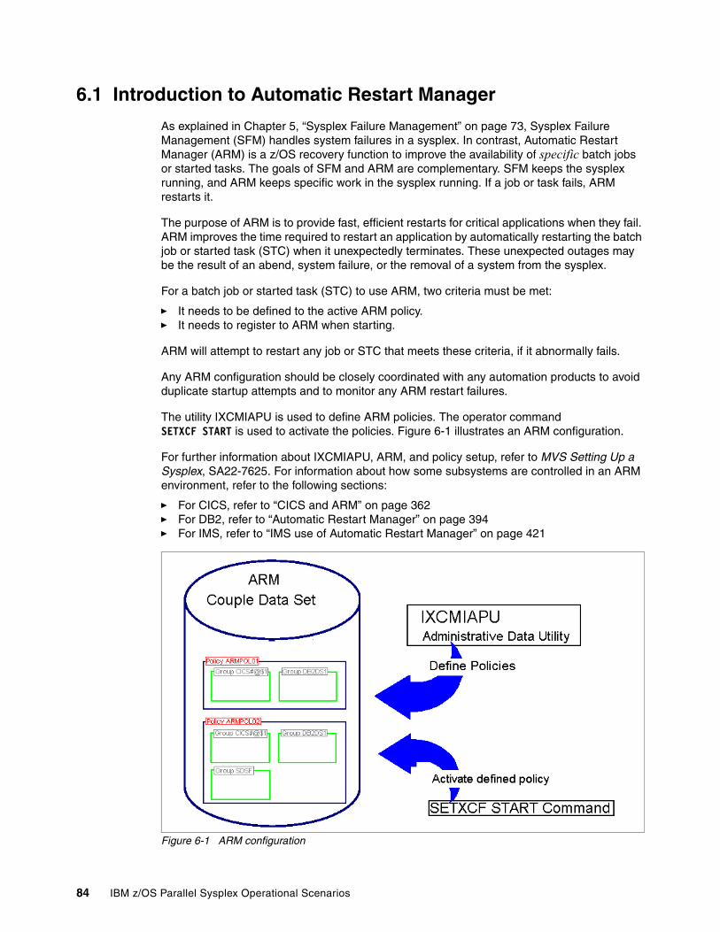
6.1 Introduction to Automatic Restart Manager
As explained in Chapter 5, “Sysplex Failure Management” on page 73, Sysplex Failure Management (SFM) handles system failures in a sysplex. In contrast, Automatic Restart Manager (ARM) is a z/OS recovery function to improve the availability of specific batch jobs or started tasks. The goals of SFM and ARM are complementary. SFM keeps the sysplex running, and ARM keeps specific work in the sysplex running. If a job or task fails, ARM restarts it.
The purpose of ARM is to provide fast, efficient restarts for critical applications when they fail. ARM improves the time required to restart an application by automatically restarting the batch job or started task (STC) when it unexpectedly terminates. These unexpected outages may be the result of an abend, system failure, or the removal of a system from the sysplex.
For a batch job or started task (STC) to use ARM, two criteria must be met:
� It needs to be defined to the active ARM policy.� It needs to register to ARM when starting.
ARM will attempt to restart any job or STC that meets these criteria, if it abnormally fails.
Any ARM configuration should be closely coordinated with any automation products to avoid duplicate startup attempts and to monitor any ARM restart failures.
The utility IXCMIAPU is used to define ARM policies. The operator command SETXCF START is used to activate the policies. Figure 6-1 illustrates an ARM configuration.
For further information about IXCMIAPU, ARM, and policy setup, refer to MVS Setting Up a Sysplex, SA22-7625. For information about how some subsystems are controlled in an ARM environment, refer to the following sections:
� For CICS, refer to “CICS and ARM” on page 362� For DB2, refer to “Automatic Restart Manager” on page 394� For IMS, refer to “IMS use of Automatic Restart Manager” on page 421
Figure 6-1 ARM configuration
84 IBM z/OS Parallel Sysplex Operational Scenarios

6.2 ARM components
There are three components to ARM, as explained here.
� Each system in the sysplex must be connected to an ARM couple dataset.
� There must be an active ARM policy.
A Parallel Sysplex is governed by various policies, such as CFRM policies and WLM policies. A policy is a set of rules and actions that systems in a sysplex are to follow. A policy allows MVS to manage specific resources in compliance with your system and resource requirements, but with little operator intervention.
The ARM policy allows you to define how MVS is to manage automatic restarts of started tasks and batch jobs that are registered as elements of Automatic Restart Manager. There can be multiple ARM policies defined but only one ARM policy active at any one time.
� The STC or job must register to ARM.
Registration is how the program communicates its restart requirements to ARM. A program calls the ARM API, using the IXCARM macro. When a program registers, it is in one of these states:
Starting The element is executing and has registered.
Available The element is executing, has registered, and has indicated that it is ready for work.
Available-to The element was restarted and has registered, but has not indicated it is ready to work. After a time-out period has expired, ARM will consider it available.
Failed The element is registered and has terminated without deregistering. ARM has not yet restarted it, or is beginning to restart it.
Restarting The element failed, and ARM is restarting it. The element may be executing and has yet to register again with ARM, or job scheduling factors may be delaying its start.
WaitPred The element is waiting for all predecessor programs to complete initialization.
Recovering The element has been restarted by ARM and has registered, but has not indicated it is ready for work.
A system is considered ARM-enabled if it is connected to an ARM Couple Data Set. During an IPL of an ARM-enabled system, the system indicates which ARM datasets it has connected to, as shown in Figure 6-3 on page 86.
Note: A batch job or started task registered with Automatic Restart Manager can only be restarted within the same JES XCF group. That is, it can only be restarted in the same JES2 MAS or the same JES3 complex.
Chapter 6. Automatic Restart Manager 85
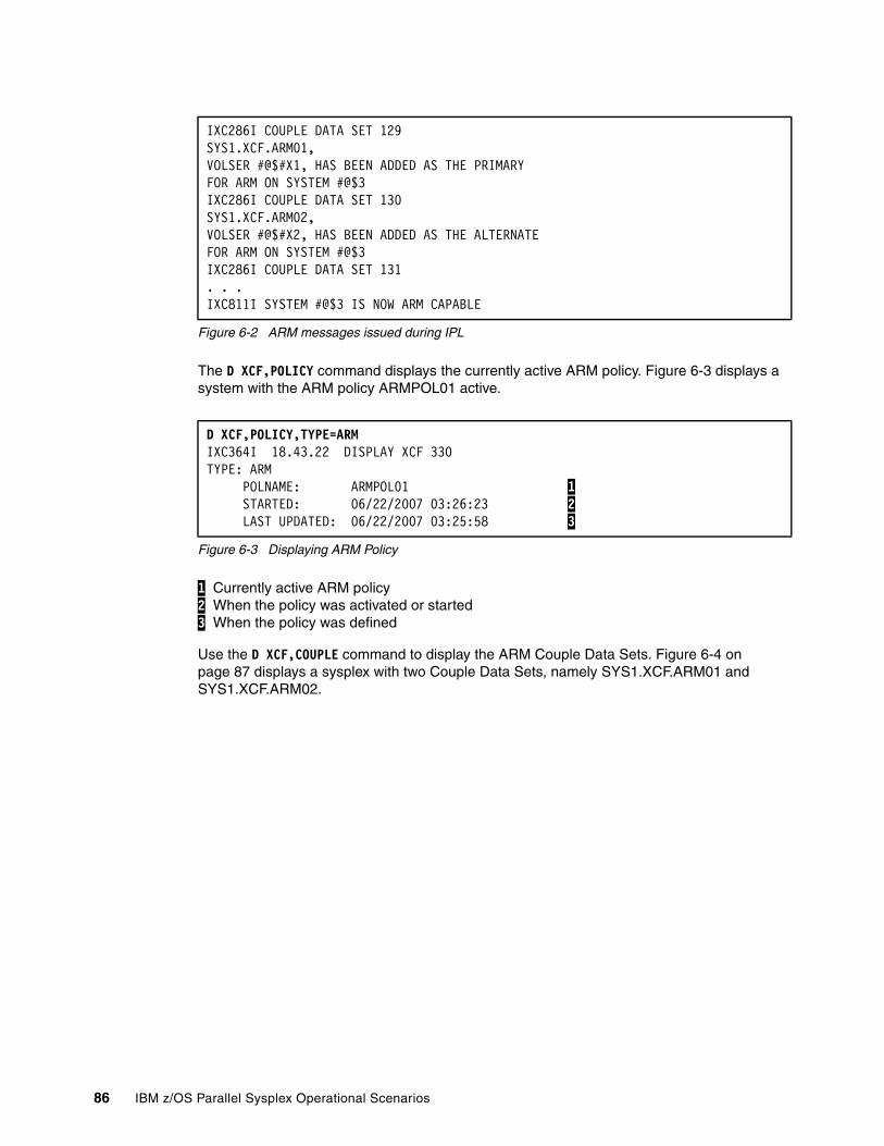
Figure 6-2 ARM messages issued during IPL
The D XCF,POLICY command displays the currently active ARM policy. Figure 6-3 displays a system with the ARM policy ARMPOL01 active.
Figure 6-3 Displaying ARM Policy
1 Currently active ARM policy 2 When the policy was activated or started 3 When the policy was defined
Use the D XCF,COUPLE command to display the ARM Couple Data Sets. Figure 6-4 on page 87 displays a sysplex with two Couple Data Sets, namely SYS1.XCF.ARM01 and SYS1.XCF.ARM02.
IXC286I COUPLE DATA SET 129SYS1.XCF.ARM01,VOLSER #@$#X1, HAS BEEN ADDED AS THE PRIMARYFOR ARM ON SYSTEM #@$3IXC286I COUPLE DATA SET 130SYS1.XCF.ARM02,VOLSER #@$#X2, HAS BEEN ADDED AS THE ALTERNATEFOR ARM ON SYSTEM #@$3IXC286I COUPLE DATA SET 131. . . IXC811I SYSTEM #@$3 IS NOW ARM CAPABLE
D XCF,POLICY,TYPE=ARMIXC364I 18.43.22 DISPLAY XCF 330TYPE: ARM POLNAME: ARMPOL01 1 STARTED: 06/22/2007 03:26:23 2 LAST UPDATED: 06/22/2007 03:25:58 3
86 IBM z/OS Parallel Sysplex Operational Scenarios
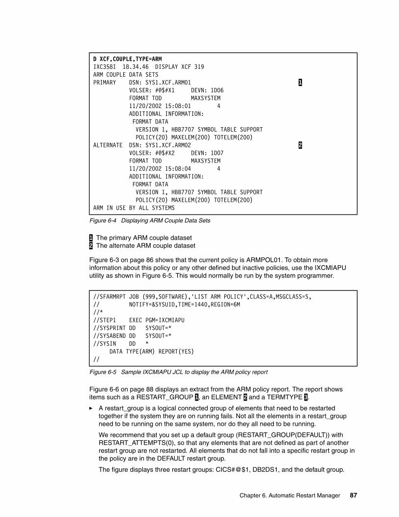
Figure 6-4 Displaying ARM Couple Data Sets
1 The primary ARM couple dataset 2 The alternate ARM couple dataset
Figure 6-3 on page 86 shows that the current policy is ARMPOL01. To obtain more information about this policy or any other defined but inactive policies, use the IXCMIAPU utility as shown in Figure 6-5. This would normally be run by the system programmer.
Figure 6-5 Sample IXCMIAPU JCL to display the ARM policy report
Figure 6-6 on page 88 displays an extract from the ARM policy report. The report shows items such as a RESTART_GROUP 1, an ELEMENT 2 and a TERMTYPE 3.
� A restart_group is a logical connected group of elements that need to be restarted together if the system they are on running fails. Not all the elements in a restart_group need to be running on the same system, nor do they all need to be running.
We recommend that you set up a default group (RESTART_GROUP(DEFAULT)) with RESTART_ATTEMPTS(0), so that any elements that are not defined as part of another restart group are not restarted. All elements that do not fall into a specific restart group in the policy are in the DEFAULT restart group.
The figure displays three restart groups: CICS#@$1, DB2DS1, and the default group.
D XCF,COUPLE,TYPE=ARMIXC358I 18.34.46 DISPLAY XCF 319ARM COUPLE DATA SETSPRIMARY DSN: SYS1.XCF.ARM01 1 VOLSER: #@$#X1 DEVN: 1D06 FORMAT TOD MAXSYSTEM 11/20/2002 15:08:01 4 ADDITIONAL INFORMATION: FORMAT DATA VERSION 1, HBB7707 SYMBOL TABLE SUPPORT POLICY(20) MAXELEM(200) TOTELEM(200)ALTERNATE DSN: SYS1.XCF.ARM02 2 VOLSER: #@$#X2 DEVN: 1D07 FORMAT TOD MAXSYSTEM 11/20/2002 15:08:04 4 ADDITIONAL INFORMATION: FORMAT DATA VERSION 1, HBB7707 SYMBOL TABLE SUPPORT POLICY(20) MAXELEM(200) TOTELEM(200)ARM IN USE BY ALL SYSTEMS
//SFARMRPT JOB (999,SOFTWARE),'LIST ARM POLICY',CLASS=A,MSGCLASS=S,// NOTIFY=&SYSUID,TIME=1440,REGION=6M//*//STEP1 EXEC PGM=IXCMIAPU//SYSPRINT DD SYSOUT=*//SYSABEND DD SYSOUT=*//SYSIN DD * DATA TYPE(ARM) REPORT(YES)//
Chapter 6. Automatic Restart Manager 87
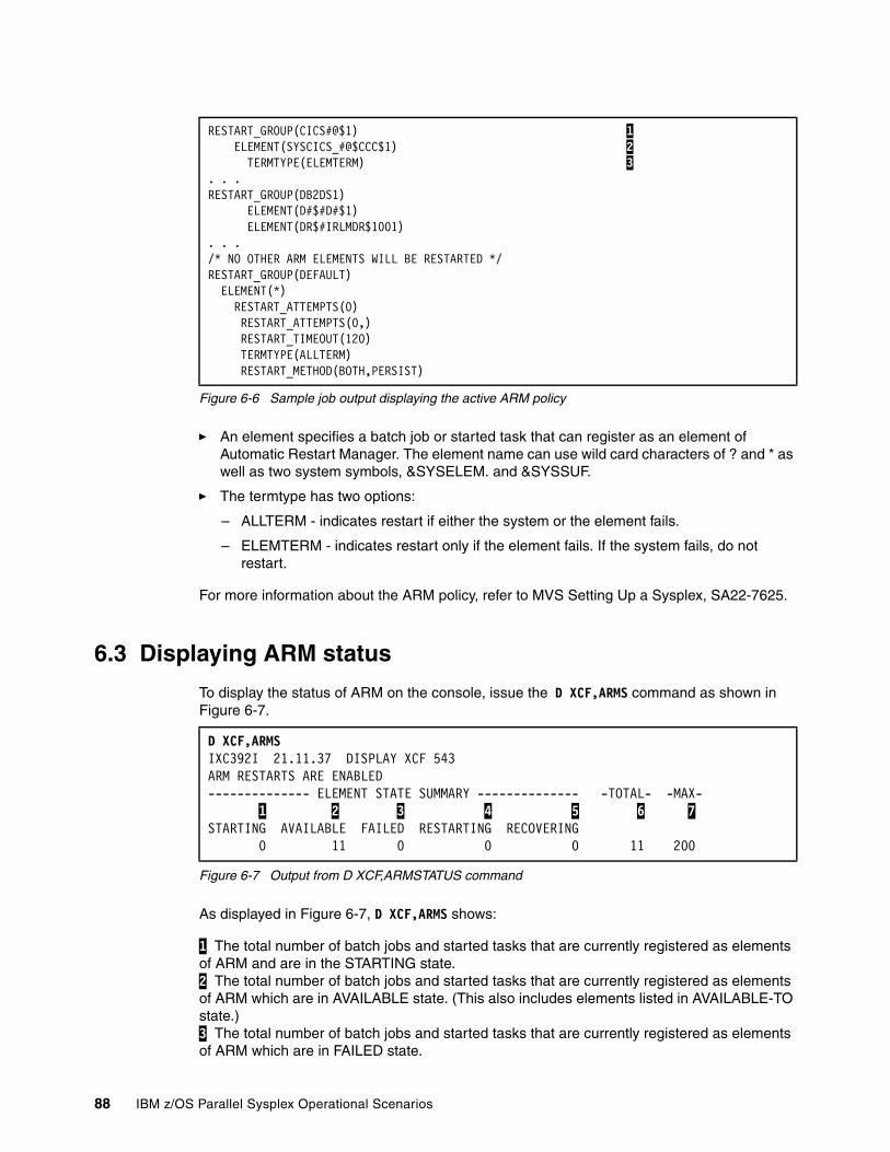
Figure 6-6 Sample job output displaying the active ARM policy
� An element specifies a batch job or started task that can register as an element of Automatic Restart Manager. The element name can use wild card characters of ? and * as well as two system symbols, &SYSELEM. and &SYSSUF.
� The termtype has two options:
– ALLTERM - indicates restart if either the system or the element fails.
– ELEMTERM - indicates restart only if the element fails. If the system fails, do not restart.
For more information about the ARM policy, refer to MVS Setting Up a Sysplex, SA22-7625.
6.3 Displaying ARM status
To display the status of ARM on the console, issue the D XCF,ARMS command as shown in Figure 6-7.
Figure 6-7 Output from D XCF,ARMSTATUS command
As displayed in Figure 6-7, D XCF,ARMS shows:
1 The total number of batch jobs and started tasks that are currently registered as elements of ARM and are in the STARTING state. 2 The total number of batch jobs and started tasks that are currently registered as elements of ARM which are in AVAILABLE state. (This also includes elements listed in AVAILABLE-TO state.) 3 The total number of batch jobs and started tasks that are currently registered as elements of ARM which are in FAILED state.
RESTART_GROUP(CICS#@$1) 1 ELEMENT(SYSCICS_#@$CCC$1) 2 TERMTYPE(ELEMTERM) 3 . . .RESTART_GROUP(DB2DS1) ELEMENT(D#$#D#$1) ELEMENT(DR$#IRLMDR$1001). . ./* NO OTHER ARM ELEMENTS WILL BE RESTARTED */RESTART_GROUP(DEFAULT) ELEMENT(*) RESTART_ATTEMPTS(0) RESTART_ATTEMPTS(0,) RESTART_TIMEOUT(120) TERMTYPE(ALLTERM) RESTART_METHOD(BOTH,PERSIST)
D XCF,ARMSIXC392I 21.11.37 DISPLAY XCF 543ARM RESTARTS ARE ENABLED-------------- ELEMENT STATE SUMMARY -------------- -TOTAL- -MAX- 1 2 3 4 5 6 7 STARTING AVAILABLE FAILED RESTARTING RECOVERING 0 11 0 0 0 11 200
88 IBM z/OS Parallel Sysplex Operational Scenarios
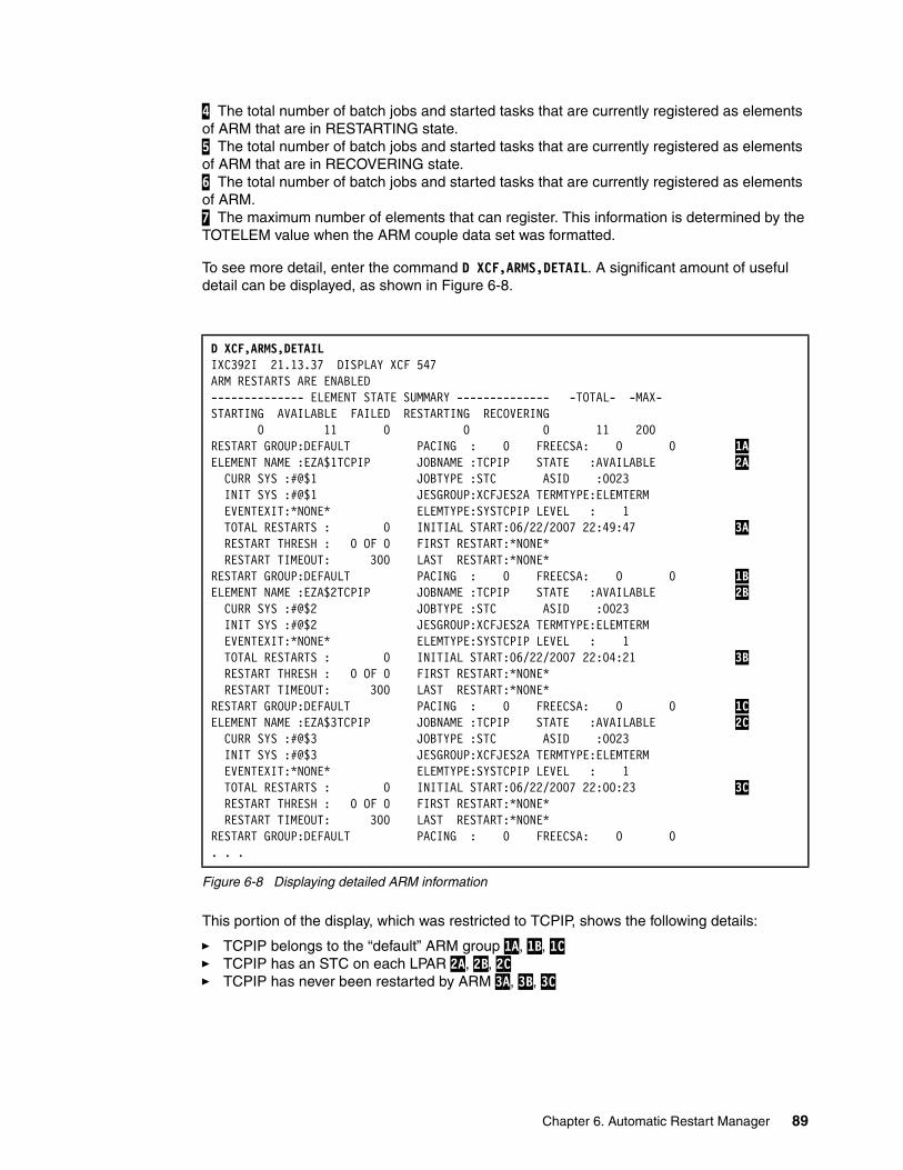
4 The total number of batch jobs and started tasks that are currently registered as elements of ARM that are in RESTARTING state. 5 The total number of batch jobs and started tasks that are currently registered as elements of ARM that are in RECOVERING state. 6 The total number of batch jobs and started tasks that are currently registered as elements of ARM. 7 The maximum number of elements that can register. This information is determined by the TOTELEM value when the ARM couple data set was formatted.
To see more detail, enter the command D XCF,ARMS,DETAIL. A significant amount of useful detail can be displayed, as shown in Figure 6-8.
Figure 6-8 Displaying detailed ARM information
This portion of the display, which was restricted to TCPIP, shows the following details:
� TCPIP belongs to the “default” ARM group 1A, 1B, 1C � TCPIP has an STC on each LPAR 2A, 2B, 2C � TCPIP has never been restarted by ARM 3A, 3B, 3C
D XCF,ARMS,DETAILIXC392I 21.13.37 DISPLAY XCF 547ARM RESTARTS ARE ENABLED-------------- ELEMENT STATE SUMMARY -------------- -TOTAL- -MAX-STARTING AVAILABLE FAILED RESTARTING RECOVERING 0 11 0 0 0 11 200RESTART GROUP:DEFAULT PACING : 0 FREECSA: 0 0 1A ELEMENT NAME :EZA$1TCPIP JOBNAME :TCPIP STATE :AVAILABLE 2A CURR SYS :#@$1 JOBTYPE :STC ASID :0023 INIT SYS :#@$1 JESGROUP:XCFJES2A TERMTYPE:ELEMTERM EVENTEXIT:*NONE* ELEMTYPE:SYSTCPIP LEVEL : 1 TOTAL RESTARTS : 0 INITIAL START:06/22/2007 22:49:47 3A RESTART THRESH : 0 OF 0 FIRST RESTART:*NONE* RESTART TIMEOUT: 300 LAST RESTART:*NONE*RESTART GROUP:DEFAULT PACING : 0 FREECSA: 0 0 1B ELEMENT NAME :EZA$2TCPIP JOBNAME :TCPIP STATE :AVAILABLE 2B CURR SYS :#@$2 JOBTYPE :STC ASID :0023 INIT SYS :#@$2 JESGROUP:XCFJES2A TERMTYPE:ELEMTERM EVENTEXIT:*NONE* ELEMTYPE:SYSTCPIP LEVEL : 1 TOTAL RESTARTS : 0 INITIAL START:06/22/2007 22:04:21 3B RESTART THRESH : 0 OF 0 FIRST RESTART:*NONE* RESTART TIMEOUT: 300 LAST RESTART:*NONE*RESTART GROUP:DEFAULT PACING : 0 FREECSA: 0 0 1C ELEMENT NAME :EZA$3TCPIP JOBNAME :TCPIP STATE :AVAILABLE 2C CURR SYS :#@$3 JOBTYPE :STC ASID :0023 INIT SYS :#@$3 JESGROUP:XCFJES2A TERMTYPE:ELEMTERM EVENTEXIT:*NONE* ELEMTYPE:SYSTCPIP LEVEL : 1 TOTAL RESTARTS : 0 INITIAL START:06/22/2007 22:00:23 3C RESTART THRESH : 0 OF 0 FIRST RESTART:*NONE* RESTART TIMEOUT: 300 LAST RESTART:*NONE*RESTART GROUP:DEFAULT PACING : 0 FREECSA: 0 0. . .
Chapter 6. Automatic Restart Manager 89
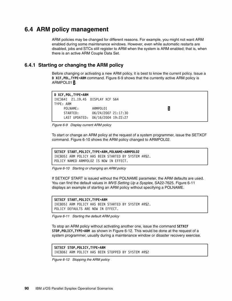
6.4 ARM policy management
ARM policies may be changed for different reasons. For example, you might not want ARM enabled during some maintenance windows. However, even while automatic restarts are disabled, jobs and STCs still register to ARM when the system is ARM enabled; that is, when there is an active ARM Couple Data Set.
6.4.1 Starting or changing the ARM policy
Before changing or activating a new ARM policy, it is best to know the current policy. Issue a D XCF,POL,TYPE=ARM command. Figure 6-9 shows that the currently active ARM policy is ARMPOL01 1.
Figure 6-9 Display current ARM policy
To start or change an ARM policy at the request of a system programmer, issue the SETXCF command. Figure 6-10 shows the ARM policy changed to ARMPOL02.
Figure 6-10 Starting or changing an ARM policy
If SETXCF START is issued without the POLNAME parameter, the ARM defaults are used. You can find the default values in MVS Setting Up a Sysplex, SA22-7625. Figure 6-11 displays an example of starting an ARM policy without specifying a POLNAME.
Figure 6-11 Starting the default ARM policy
To stop an ARM policy without activating another one, issue the command SETXCF STOP,POLICY,TYPE=ARM as shown in Figure 6-12. This would be done at the request of a system programmer, usually during a maintenance window or disaster recovery exercise.
Figure 6-12 Stopping the ARM policy
D XCF,POL,TYPE=ARMIXC364I 21.19.45 DISPLAY XCF 564TYPE: ARM POLNAME: ARMPOL01 1 STARTED: 06/24/2007 21:17:30 LAST UPDATED: 06/16/2004 19:22:27
SETXCF START,POLICY,TYPE=ARM,POLNAME=ARMPOL02 IXC805I ARM POLICY HAS BEEN STARTED BY SYSTEM #@$2.POLICY NAMED ARMPOL02 IS NOW IN EFFECT.
SETXCF START,POLICY,TYPE=ARMIXC805I ARM POLICY HAS BEEN STARTED BY SYSTEM #@$2.POLICY DEFAULTS ARE NOW IN EFFECT.
SETXCF STOP,POLICY,TYPE=ARMIXC806I ARM POLICY HAS BEEN STOPPED BY SYSTEM #@$2
90 IBM z/OS Parallel Sysplex Operational Scenarios

6.4.2 Displaying the ARM policy status
The ARM policy is sysplex in scope. This means that when the ARM policy on system #@$2 was stopped, it was also stopped on systems #@$1 and #@$3. This can be seen when you display the policy on all systems, as shown in Figure 6-13. Normally you would only need to issue the command on a single system.
Figure 6-13 Verify the ARM is stopped
6.5 Defining SDSF as a new ARM element
This section illustrates how to create a new ARM policy defining a new element, SDSF in this case. It also demonstrates how ARM can work.
SDSF is fully documented in SDSF Operation and Customization, SA22-7670. Part of SDSF is the server started task (STC). This is called “SDSF” in the following example.
6.5.1 Defining an ARM policy with SDSF
Figure 6-14 on page 92 shows part of the initial ARM policy used in this example, without SDSF. Specifically, the RESTART_GROUP(DEFAULT) section 1 has restart_attempts(0) defined.
RO *ALL,D XCF,POL,TYPE=ARMIEE421I RO *ALL,D XCF,POL,TYPE=A 638#@$1 RESPONSES -----------------IXC364I 21.48.37 DISPLAY XCF 118TYPE: ARMPOLICY NOT STARTED#@$2 RESPONSES -----------------IXC364I 21.48.37 DISPLAY XCF 637TYPE: ARMPOLICY NOT STARTED#@$3 RESPONSES -----------------IXC364I 21.48.37 DISPLAY XCF 818 TYPE: ARMPOLICY NOT STARTED
Chapter 6. Automatic Restart Manager 91
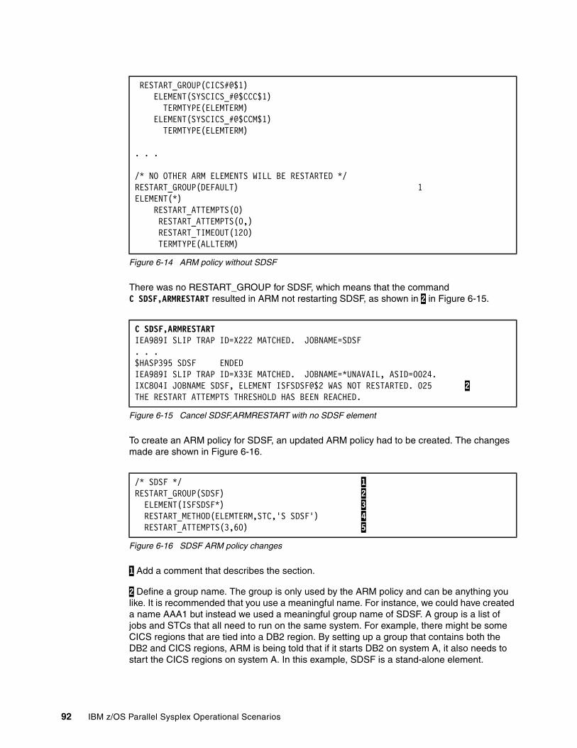
Figure 6-14 ARM policy without SDSF
There was no RESTART_GROUP for SDSF, which means that the command C SDSF,ARMRESTART resulted in ARM not restarting SDSF, as shown in 2 in Figure 6-15.
Figure 6-15 Cancel SDSF,ARMRESTART with no SDSF element
To create an ARM policy for SDSF, an updated ARM policy had to be created. The changes made are shown in Figure 6-16.
Figure 6-16 SDSF ARM policy changes
1 Add a comment that describes the section.
2 Define a group name. The group is only used by the ARM policy and can be anything you like. It is recommended that you use a meaningful name. For instance, we could have created a name AAA1 but instead we used a meaningful group name of SDSF. A group is a list of jobs and STCs that all need to run on the same system. For example, there might be some CICS regions that are tied into a DB2 region. By setting up a group that contains both the DB2 and CICS regions, ARM is being told that if it starts DB2 on system A, it also needs to start the CICS regions on system A. In this example, SDSF is a stand-alone element.
RESTART_GROUP(CICS#@$1) ELEMENT(SYSCICS_#@$CCC$1) TERMTYPE(ELEMTERM) ELEMENT(SYSCICS_#@$CCM$1) TERMTYPE(ELEMTERM)
. . .
/* NO OTHER ARM ELEMENTS WILL BE RESTARTED */RESTART_GROUP(DEFAULT) 1ELEMENT(*) RESTART_ATTEMPTS(0) RESTART_ATTEMPTS(0,) RESTART_TIMEOUT(120) TERMTYPE(ALLTERM)
C SDSF,ARMRESTARTIEA989I SLIP TRAP ID=X222 MATCHED. JOBNAME=SDSF. . .$HASP395 SDSF ENDEDIEA989I SLIP TRAP ID=X33E MATCHED. JOBNAME=*UNAVAIL, ASID=0024.IXC804I JOBNAME SDSF, ELEMENT ISFSDSF@$2 WAS NOT RESTARTED. 025 2 THE RESTART ATTEMPTS THRESHOLD HAS BEEN REACHED.
/* SDSF */ 1 RESTART_GROUP(SDSF) 2 ELEMENT(ISFSDSF*) 3 RESTART_METHOD(ELEMTERM,STC,'S SDSF') 4 RESTART_ATTEMPTS(3,60) 5
92 IBM z/OS Parallel Sysplex Operational Scenarios
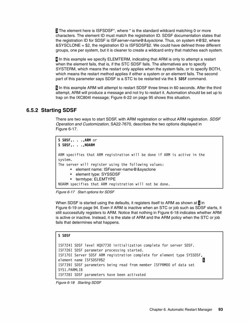
3 The element here is ISFSDSF*, where * is the standard wildcard matching 0 or more characters. The element ID must match the registration ID. SDSF documentation states that the registration ID for SDSF is ISFserver-name@&sysclone. Thus, on system #@$2, where &SYSCLONE = $2, the registration ID is ISFSDSF$2. We could have defined three different groups, one per system, but it is cleaner to create a wildcard entry that matches each system.
4 In this example we specify ELEMTERM, indicating that ARM is only to attempt a restart when the element fails, that is, if the STC SDSF fails. The alternatives are to specify SYSTERM, which means the restart only applies when the system fails, or to specify BOTH, which means the restart method applies if either a system or an element fails. The second part of this parameter says SDSF is a STC to be restarted via the S SDSF command.
5 In this example ARM will attempt to restart SDSF three times in 60 seconds. After the third attempt, ARM will produce a message and not try to restart it. Automation should be set up to trap on the IXC804I message; Figure 6-22 on page 95 shows this situation.
6.5.2 Starting SDSF
There are two ways to start SDSF, with ARM registration or without ARM registration. SDSF Operation and Customization, SA22-7670, describes the two options displayed in Figure 6-17.
Figure 6-17 Start options for SDSF
When SDSF is started using the defaults, it registers itself to ARM as shown at 1 in Figure 6-19 on page 94. Even if ARM is inactive when an STC or job such as SDSF starts, it still successfully registers to ARM. Notice that nothing in Figure 6-18 indicates whether ARM is active or inactive. Instead, it is the state of ARM and the ARM policy when the STC or job fails that determines what happens.
Figure 6-18 Starting SDSF
S SDSF,. . .,ARM orS SDSF,. . .,NOARM
ARM specifies that ARM registration will be done if ARM is active in the system. The server will register using the following values:
• element name: ISFserver-name@&sysclone• element type: SYSSDSF• termtype: ELEMTYPE
NOARM specifies that ARM registration will not be done.
S SDSF
ISF724I SDSF level HQX7730 initialization complete for server SDSF.ISF726I SDSF parameter processing started.ISF170I Server SDSF ARM registration complete for element type SYSSDSF,element name ISFSDSF@$2 1 ISF739I SDSF parameters being read from member ISFPRM00 of data set SYS1.PARMLIBISF728I SDSF parameters have been activated
Chapter 6. Automatic Restart Manager 93
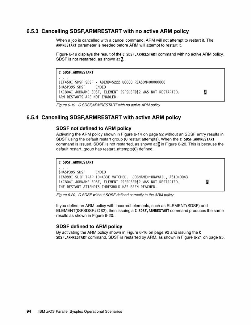
6.5.3 Cancelling SDSF,ARMRESTART with no active ARM policy
When a job is cancelled with a cancel command, ARM will not attempt to restart it. The ARMRESTART parameter is needed before ARM will attempt to restart it.
Figure 6-19 displays the result of the C SDSF,ARMRESTART command with no active ARM policy. SDSF is not restarted, as shown at A.
Figure 6-19 C SDSF,ARMRESTART with no active ARM policy
6.5.4 Cancelling SDSF,ARMRESTART with active ARM policy
SDSF not defined to ARM policyActivating the ARM policy shown in Figure 6-14 on page 92 without an SDSF entry results in SDSF using the default restart group (0 restart attempts). When the C SDSF,ARMRESTART command is issued, SDSF is not restarted, as shown at B in Figure 6-20. This is because the default restart_group has restart_attempts(0) defined.
Figure 6-20 C SDSF without SDSF defined correctly to the ARM policy
If you define an ARM policy with incorrect elements, such as ELEMENT(SDSF) and ELEMENT(ISFSDSF#@$2), then issuing a C SDSF,ARMRESTART command produces the same results as shown in Figure 6-20.
SDSF defined to ARM policyBy activating the ARM policy shown in Figure 6-16 on page 92 and issuing the C SDSF,ARMRESTART command, SDSF is restarted by ARM, as shown in Figure 6-21 on page 95.
C SDSF,ARMRESTART. . .IEF450I SDSF SDSF - ABEND=S222 U0000 REASON=00000000$HASP395 SDSF ENDEDIXC804I JOBNAME SDSF, ELEMENT ISFSDSF@$2 WAS NOT RESTARTED. A ARM RESTARTS ARE NOT ENABLED.
C SDSF,ARMRESTART. . .$HASP395 SDSF ENDEDIEA989I SLIP TRAP ID=X33E MATCHED. JOBNAME=*UNAVAIL, ASID=0043.IXC804I JOBNAME SDSF, ELEMENT ISFSDSF@$2 WAS NOT RESTARTED. B THE RESTART ATTEMPTS THRESHOLD HAS BEEN REACHED.
94 IBM z/OS Parallel Sysplex Operational Scenarios
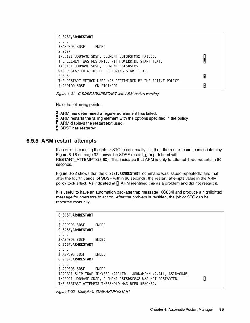
Figure 6-21 C SDSF,ARMRESTART with ARM restart working
Note the following points:
1 ARM has determined a registered element has failed. 2 ARM restarts the failing element with the options specified in the policy. 3 ARM displays the restart text used. 4 SDSF has restarted.
6.5.5 ARM restart_attempts
If an error is causing the job or STC to continually fail, then the restart count comes into play. Figure 6-16 on page 92 shows the SDSF restart_group defined with RESTART_ATTEMPTS(3,60). This indicates that ARM is only to attempt three restarts in 60 seconds.
Figure 6-22 shows that the C SDSF,ARMRESTART command was issued repeatedly, and that after the fourth cancel of SDSF within 60 seconds, the restart_attempts value in the ARM policy took effect. As indicated at 1, ARM identified this as a problem and did not restart it.
It is useful to have an automation package trap message IXC804I and produce a highlighted message for operators to act on. After the problem is rectified, the job or STC can be restarted manually.
Figure 6-22 Multiple C SDSF,ARMRESTART
C SDSF,ARMRESTART. . .$HASP395 SDSF ENDEDS SDSFIXC812I JOBNAME SDSF, ELEMENT ISFSDSF@$2 FAILED. 1 THE ELEMENT WAS RESTARTED WITH OVERRIDE START TEXT. 2 IXC813I JOBNAME SDSF, ELEMENT ISFSDSF@$WAS RESTARTED WITH THE FOLLOWING START TEXT:S SDSF 3 THE RESTART METHOD USED WAS DETERMINED BY THE ACTIVE POLICY.$HASP100 SDSF ON STCINRDR 4
C SDSF,ARMRESTART. . .$HASP395 SDSF ENDEDC SDSF,ARMRESTART. . .$HASP395 SDSF ENDEDC SDSF,ARMRESTART. . .$HASP395 SDSF ENDEDC SDSF,ARMRESTART. . .$HASP395 SDSF ENDEDIEA989I SLIP TRAP ID=X33E MATCHED. JOBNAME=*UNAVAIL, ASID=0048.IXC804I JOBNAME SDSF, ELEMENT ISFSDSF@$2 WAS NOT RESTARTED. 1 THE RESTART ATTEMPTS THRESHOLD HAS BEEN REACHED.
Chapter 6. Automatic Restart Manager 95

6.6 ARM and ARMWRAP
IBM developed a program called ARMWRAP that provides the ability to exploit ARM without having to make changes to the application code. To prevent any program from using the ARM facilities, SAF control was added to ARMWRAP. This allows RACF or other security products to control its usage.
6.7.2, “Cross-system restarts” on page 100 explains how ARM can restart a job or STC on different systems. In normal circumstances there is an instance of the SDSF server running on every system; thus, it does not make sense to configure SDSF for a cross-system restart. Instead, a procedure known as SLEEPY was created. It runs a program that loops through 24 stimer calls of 10 minutes each, so that it essentially sleeps for 4 hours and then finishes. The SLEEPY program does not perform its own ARM registration. Instead, it makes use of the facility ARMWRAP.
Figure 6-23 displays the JCL for PROC SLEEPY without making use of the ARMWRAP facility.
Figure 6-23 SLEEPY without ARMWRAP
To make use of the ARMWRAP facility, two steps must be added to the proc. These steps can be seen in Figure 6-24.
Figure 6-24 SLEEPY with ARMWRAP
1 This is the first step in the new PROC that runs the program ARMWRAP. 2 ARMWRAP takes parameters to register and define the ARM values such as ELEMTYPE, ELEMENT and TERMTYPE. 3 The step (or steps) that form the proc are left as they were before. 4 When the proc finishes normally, it needs to deregister.
After SLEEPY is configured to work with ARMWRAP, it must be added to the ARM policy. In our case, because we wanted SLEEPY to move to a different system in the event of a system failure, we added the lines seen in Figure 6-25 on page 97 to the current policy.
//SLEEPY PROC//SLEEPY EXEC PGM=SLEEPY//*
//SLEEPY PROC//*//* Register element 'SLEEPY' element type 'APPLTYPE' with ARM//* Requires access to SAF FACILITY IXCARM.APPLTYPE.SLEEPY//*//ARMREG EXEC PGM=ARMWRAP, 1 // PARM=('REQUEST=REGISTER,READYBYMSG=N,', 2 // 'TERMTYPE=ALLTERM,ELEMENT=SLEEPY,','ELEMTYPE=APPLTYPE')//*//SLEEPY EXEC PGM=SLEEPY 3 //*//* For normal termination, deregister from ARM//*//ARMDREG EXEC PGM=ARMWRAP,PARM=('REQUEST=DEREGISTER') 4 //SYSABEND DD SYSOUT=*
96 IBM z/OS Parallel Sysplex Operational Scenarios
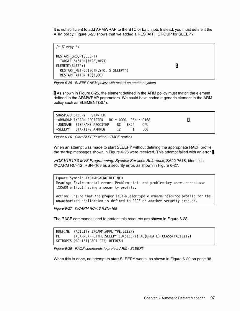
It is not sufficient to add ARMWRAP to the STC or batch job. Instead, you must define it the ARM policy. Figure 6-25 shows that we added a RESTART_GROUP for SLEEPY.
Figure 6-25 SLEEPY ARM policy with restart on another system
1 As shown in Figure 6-25, the element defined in the ARM policy must match the element defined in the ARMWRAP parameters. We could have coded a generic element in the ARM policy such as ELEMENT(SL*).
Figure 6-26 Start SLEEPY without RACF profiles
When an attempt was made to start SLEEPY without defining the appropriate RACF profile, the startup messages shown in Figure 6-26 were received. This attempt failed with an error 1.
z/OS V1R10.0 MVS Programming: Sysplex Services Reference, SA22-7618, identifies IXCARM RC=12, RSN=168 as a security error, as shown in Figure 6-27.
Figure 6-27 IXCARM RC=12 RSN=168
The RACF commands used to protect this resource are shown in Figure 6-28.
Figure 6-28 RACF commands to protect ARM - SLEEPY
When this is done, an attempt to start SLEEPY works, as shown in Figure 6-29 on page 98.
/* Sleepy */
RESTART_GROUP(SLEEPY) TARGET_SYSTEM(#@$2,#@$3)ELEMENT(SLEEPY) 1 RESTART_METHOD(BOTH,STC,'S SLEEPY') RESTART_ATTEMPTS(3,60)
$HASP373 SLEEPY STARTED+ARMWRAP IXCARM REGISTER RC = 000C RSN = 0168 1 -JOBNAME STEPNAME PROCSTEP RC EXCP CPU-SLEEPY STARTING ARMREG 12 1 .00
Equate Symbol: IXCARMSAFNOTDEFINEDMeaning: Environmental error. Problem state and problem key users cannot use IXCARM without having a security profile.
Action: Ensure that the proper IXCARM.elemtype.elemname resource profile for the unauthorized application is defined to RACF or another security product.
RDEFINE FACILITY IXCARM.APPLTYPE.SLEEPYPE IXCARM.APPLTYPE.SLEEPY ID(SLEEPY) AC(UPDATE) CLASS(FACILITY)SETROPTS RACLIST(FACILITY) REFRESH
Chapter 6. Automatic Restart Manager 97
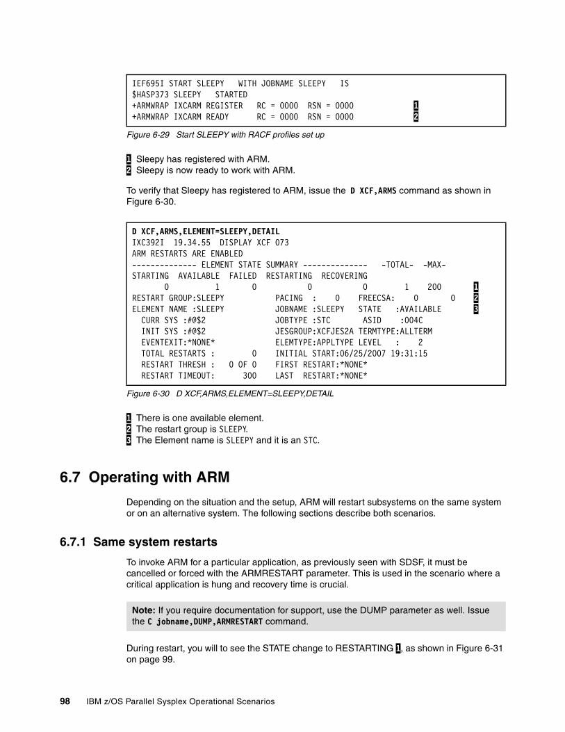
Figure 6-29 Start SLEEPY with RACF profiles set up
1 Sleepy has registered with ARM. 2 Sleepy is now ready to work with ARM.
To verify that Sleepy has registered to ARM, issue the D XCF,ARMS command as shown in Figure 6-30.
Figure 6-30 D XCF,ARMS,ELEMENT=SLEEPY,DETAIL
1 There is one available element. 2 The restart group is SLEEPY. 3 The Element name is SLEEPY and it is an STC.
6.7 Operating with ARM
Depending on the situation and the setup, ARM will restart subsystems on the same system or on an alternative system. The following sections describe both scenarios.
6.7.1 Same system restarts
To invoke ARM for a particular application, as previously seen with SDSF, it must be cancelled or forced with the ARMRESTART parameter. This is used in the scenario where a critical application is hung and recovery time is crucial.
During restart, you will to see the STATE change to RESTARTING 1, as shown in Figure 6-31 on page 99.
IEF695I START SLEEPY WITH JOBNAME SLEEPY IS $HASP373 SLEEPY STARTED +ARMWRAP IXCARM REGISTER RC = 0000 RSN = 0000 1 +ARMWRAP IXCARM READY RC = 0000 RSN = 0000 2
D XCF,ARMS,ELEMENT=SLEEPY,DETAILIXC392I 19.34.55 DISPLAY XCF 073ARM RESTARTS ARE ENABLED-------------- ELEMENT STATE SUMMARY -------------- -TOTAL- -MAX-STARTING AVAILABLE FAILED RESTARTING RECOVERING 0 1 0 0 0 1 200 1 RESTART GROUP:SLEEPY PACING : 0 FREECSA: 0 0 2 ELEMENT NAME :SLEEPY JOBNAME :SLEEPY STATE :AVAILABLE 3 CURR SYS :#@$2 JOBTYPE :STC ASID :004C INIT SYS :#@$2 JESGROUP:XCFJES2A TERMTYPE:ALLTERM EVENTEXIT:*NONE* ELEMTYPE:APPLTYPE LEVEL : 2 TOTAL RESTARTS : 0 INITIAL START:06/25/2007 19:31:15 RESTART THRESH : 0 OF 0 FIRST RESTART:*NONE* RESTART TIMEOUT: 300 LAST RESTART:*NONE*
Note: If you require documentation for support, use the DUMP parameter as well. Issue the C jobname,DUMP,ARMRESTART command.
98 IBM z/OS Parallel Sysplex Operational Scenarios
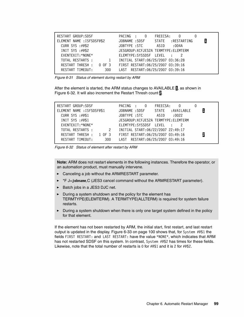
Figure 6-31 Status of element during restart by ARM
After the element is started, the ARM status changes to AVAILABLE 1, as shown in Figure 6-32. It will also increment the Restart Thresh count 2.
Figure 6-32 Status of element after restart by ARM
If the element has not been restarted by ARM, the initial start, first restart, and last restart output is updated in the display. Figure 6-33 on page 100 shows that, for System #@$1 the fields FIRST RESTART: and LAST RESTART: have the value *NONE*, which indicates that ARM has not restarted SDSF on this system. In contrast, System #@$2 has times for these fields. Likewise, note that the total number of restarts is 0 for #@$1 and it is 2 for #@$2.
RESTART GROUP:SDSF PACING : 0 FREECSA: 0 0ELEMENT NAME :ISFSDSF@$2 JOBNAME :SDSF STATE :RESTARTING 1 CURR SYS :#@$2 JOBTYPE :STC ASID :004A INIT SYS :#@$2 JESGROUP:XCFJES2A TERMTYPE:ELEMTERM EVENTEXIT:*NONE* ELEMTYPE:SYSSDSF LEVEL : 2 TOTAL RESTARTS : 1 INITIAL START:06/25/2007 03:36:28 RESTART THRESH : 0 OF 3 FIRST RESTART:06/25/2007 03:39:16 RESTART TIMEOUT: 300 LAST RESTART:06/25/2007 03:39:16
RESTART GROUP:SDSF PACING : 0 FREECSA: 0 0ELEMENT NAME :ISFSDSF@$1 JOBNAME :SDSF STATE :AVAILABLE 1 CURR SYS :#@$1 JOBTYPE :STC ASID :0022 INIT SYS :#@$1 JESGROUP:XCFJES2A TERMTYPE:ELEMTERM EVENTEXIT:*NONE* ELEMTYPE:SYSSDSF LEVEL : 2 TOTAL RESTARTS : 2 INITIAL START:06/22/2007 22:49:17 RESTART THRESH : 1 OF 3 FIRST RESTART:06/25/2007 03:49:16 2 RESTART TIMEOUT: 300 LAST RESTART:06/25/2007 03:49:16
Note: ARM does not restart elements in the following instances. Therefore the operator, or an automation product, must manually intervene.
� Canceling a job without the ARMRESTART parameter.
� *F J=jobname,C (JES3 cancel command without the ARMRESTART parameter).
� Batch jobs in a JES3 DJC net.
� During a system shutdown and the policy for the element has TERMTYPE(ELEMTERM). A TERMTYPE(ALLTERM) is required for system failure restarts.
� During a system shutdown when there is only one target system defined in the policy for that element.
Chapter 6. Automatic Restart Manager 99
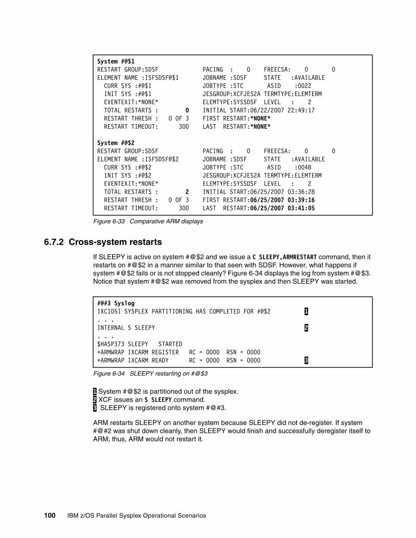
Figure 6-33 Comparative ARM displays
6.7.2 Cross-system restarts
If SLEEPY is active on system #@$2 and we issue a C SLEEPY,ARMRESTART command, then it restarts on #@$2 in a manner similar to that seen with SDSF. However, what happens if system #@$2 fails or is not stopped cleanly? Figure 6-34 displays the log from system #@$3. Notice that system #@$2 was removed from the sysplex and then SLEEPY was started.
Figure 6-34 SLEEPY restarting on #@$3
1 System #@$2 is partitioned out of the sysplex. 2 XCF issues an S SLEEPY command. 3 SLEEPY is registered onto system #@#3.
ARM restarts SLEEPY on another system because SLEEPY did not de-register. If system #@#2 was shut down cleanly, then SLEEPY would finish and successfully deregister itself to ARM; thus, ARM would not restart it.
System #@$1RESTART GROUP:SDSF PACING : 0 FREECSA: 0 0ELEMENT NAME :ISFSDSF@$1 JOBNAME :SDSF STATE :AVAILABLE CURR SYS :#@$1 JOBTYPE :STC ASID :0022 INIT SYS :#@$1 JESGROUP:XCFJES2A TERMTYPE:ELEMTERM EVENTEXIT:*NONE* ELEMTYPE:SYSSDSF LEVEL : 2 TOTAL RESTARTS : 0 INITIAL START:06/22/2007 22:49:17 RESTART THRESH : 0 OF 3 FIRST RESTART:*NONE* RESTART TIMEOUT: 300 LAST RESTART:*NONE*
System #@$2RESTART GROUP:SDSF PACING : 0 FREECSA: 0 0ELEMENT NAME :ISFSDSF@$2 JOBNAME :SDSF STATE :AVAILABLE CURR SYS :#@$2 JOBTYPE :STC ASID :004B INIT SYS :#@$2 JESGROUP:XCFJES2A TERMTYPE:ELEMTERM EVENTEXIT:*NONE* ELEMTYPE:SYSSDSF LEVEL : 2 TOTAL RESTARTS : 2 INITIAL START:06/25/2007 03:36:28 RESTART THRESH : 0 OF 3 FIRST RESTART:06/25/2007 03:39:16 RESTART TIMEOUT: 300 LAST RESTART:06/25/2007 03:41:05
#@#3 SyslogIXC105I SYSPLEX PARTITIONING HAS COMPLETED FOR #@$2 1 . . .INTERNAL S SLEEPY 2 . . .$HASP373 SLEEPY STARTED+ARMWRAP IXCARM REGISTER RC = 0000 RSN = 0000+ARMWRAP IXCARM READY RC = 0000 RSN = 0000 3
100 IBM z/OS Parallel Sysplex Operational Scenarios

Chapter 7. Coupling Facility considerations in a Parallel Sysplex
This chapter provides details of operational considerations of a Coupling Facility. It includes:
� Overview of the CF
� Displaying the CF
� Displaying structures in the CF
� Managing the CF
� Rebuilding and moving structures
7
© Copyright IBM Corp. 2009. All rights reserved. 101
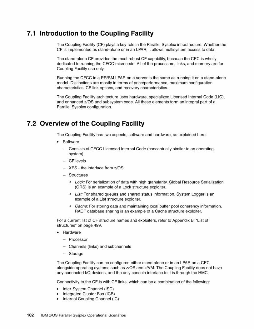
7.1 Introduction to the Coupling Facility
The Coupling Facility (CF) plays a key role in the Parallel Sysplex infrastructure. Whether the CF is implemented as stand-alone or in an LPAR, it allows multisystem access to data.
The stand-alone CF provides the most robust CF capability, because the CEC is wholly dedicated to running the CFCC microcode. All of the processors, links, and memory are for Coupling Facility use only.
Running the CFCC in a PR/SM LPAR on a server is the same as running it on a stand-alone model. Distinctions are mostly in terms of price/performance, maximum configuration characteristics, CF link options, and recovery characteristics.
The Coupling Facility architecture uses hardware, specialized Licensed Internal Code (LIC), and enhanced z/OS and subsystem code. All these elements form an integral part of a Parallel Sysplex configuration.
7.2 Overview of the Coupling Facility
The Coupling Facility has two aspects, software and hardware, as explained here:
� Software
– Consists of CFCC Licensed Internal Code (conceptually similar to an operating system).
– CF levels
– XES - the interface from z/OS
– Structures
• Lock: For serialization of data with high granularity. Global Resource Serialization (GRS) is an example of a Lock structure exploiter.
• List: For shared queues and shared status information. System Logger is an example of a List structure exploiter.
• Cache: For storing data and maintaining local buffer pool coherency information. RACF database sharing is an example of a Cache structure exploiter.
For a current list of CF structure names and exploiters, refer to Appendix B, “List of structures” on page 499.
� Hardware
– Processor
– Channels (links) and subchannels
– Storage
The Coupling Facility can be configured either stand-alone or in an LPAR on a CEC alongside operating systems such as z/OS and z/VM. The Coupling Facility does not have any connected I/O devices, and the only console interface to it is through the HMC.
Connectivity to the CF is with CF links, which can be a combination of the following:
� Inter-System Channel (ISC)� Integrated Cluster Bus (ICB)� Internal Coupling Channel (IC)
102 IBM z/OS Parallel Sysplex Operational Scenarios
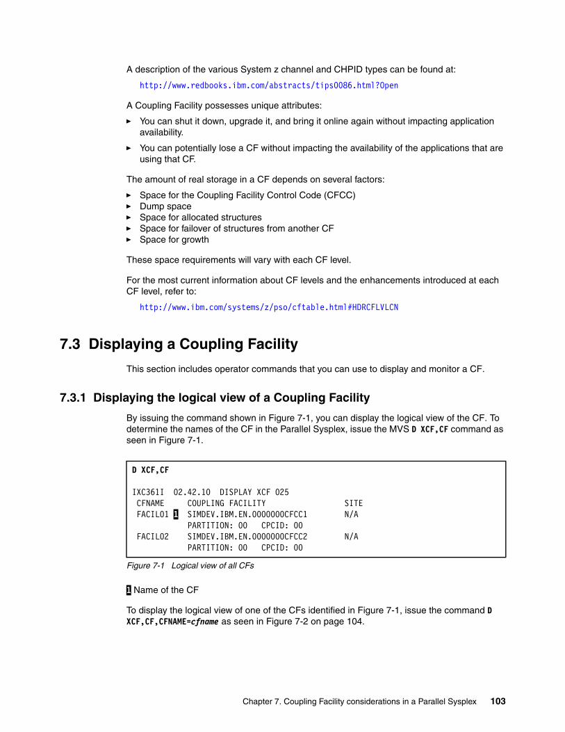
A description of the various System z channel and CHPID types can be found at:
http://www.redbooks.ibm.com/abstracts/tips0086.html?Open
A Coupling Facility possesses unique attributes:
� You can shut it down, upgrade it, and bring it online again without impacting application availability.
� You can potentially lose a CF without impacting the availability of the applications that are using that CF.
The amount of real storage in a CF depends on several factors:
� Space for the Coupling Facility Control Code (CFCC)� Dump space� Space for allocated structures� Space for failover of structures from another CF� Space for growth
These space requirements will vary with each CF level.
For the most current information about CF levels and the enhancements introduced at each CF level, refer to:
http://www.ibm.com/systems/z/pso/cftable.html#HDRCFLVLCN
7.3 Displaying a Coupling Facility
This section includes operator commands that you can use to display and monitor a CF.
7.3.1 Displaying the logical view of a Coupling Facility
By issuing the command shown in Figure 7-1, you can display the logical view of the CF. To determine the names of the CF in the Parallel Sysplex, issue the MVS D XCF,CF command as seen in Figure 7-1.
Figure 7-1 Logical view of all CFs
1 Name of the CF
To display the logical view of one of the CFs identified in Figure 7-1, issue the command D XCF,CF,CFNAME=cfname as seen in Figure 7-2 on page 104.
D XCF,CF
IXC361I 02.42.10 DISPLAY XCF 025 CFNAME COUPLING FACILITY SITE FACIL01 1 SIMDEV.IBM.EN.0000000CFCC1 N/A PARTITION: 00 CPCID: 00 FACIL02 SIMDEV.IBM.EN.0000000CFCC2 N/A PARTITION: 00 CPCID: 00
Chapter 7. Coupling Facility considerations in a Parallel Sysplex 103
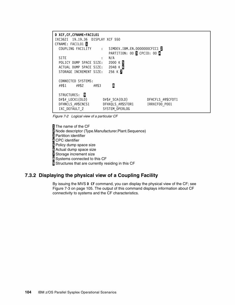
Figure 7-2 Logical view of a particular CF
1 The name of the CF 2 Node descriptor (Type.Manufacturer.Plant.Sequence) 3 Partition identifier 4 CPC identifier 5 Policy dump space size 6 Actual dump space size 7 Storage increment size 8 Systems connected to this CF 9 Structures that are currently residing in this CF
7.3.2 Displaying the physical view of a Coupling Facility
By issuing the MVS D CF command, you can display the physical view of the CF; see Figure 7-3 on page 105. The output of this command displays information about CF connectivity to systems and the CF characteristics.
D XCF,CF,CFNAME=FACIL01 IXC362I 19.19.36 DISPLAY XCF 550 CFNAME: FACIL01 1 COUPLING FACILITY : SIMDEV.IBM.EN.0000000CFCC1 2 PARTITION: 00 3 CPCID: 00 4 SITE : N/A POLICY DUMP SPACE SIZE: 2000 K 5 ACTUAL DUMP SPACE SIZE: 2048 K 6 STORAGE INCREMENT SIZE: 256 K 7 CONNECTED SYSTEMS: #@$1 #@$2 #@$3 8 STRUCTURES: 9 D#$#_LOCK1(OLD) D#$#_SCA(OLD) DFHCFLS_#@$CFDT1 DFHNCLS_#@$CNCS1 DFHXQLS_#@$STOR1 IRRXCF00_P001 IXC_DEFAULT_2 SYSTEM_OPERLOG
104 IBM z/OS Parallel Sysplex Operational Scenarios
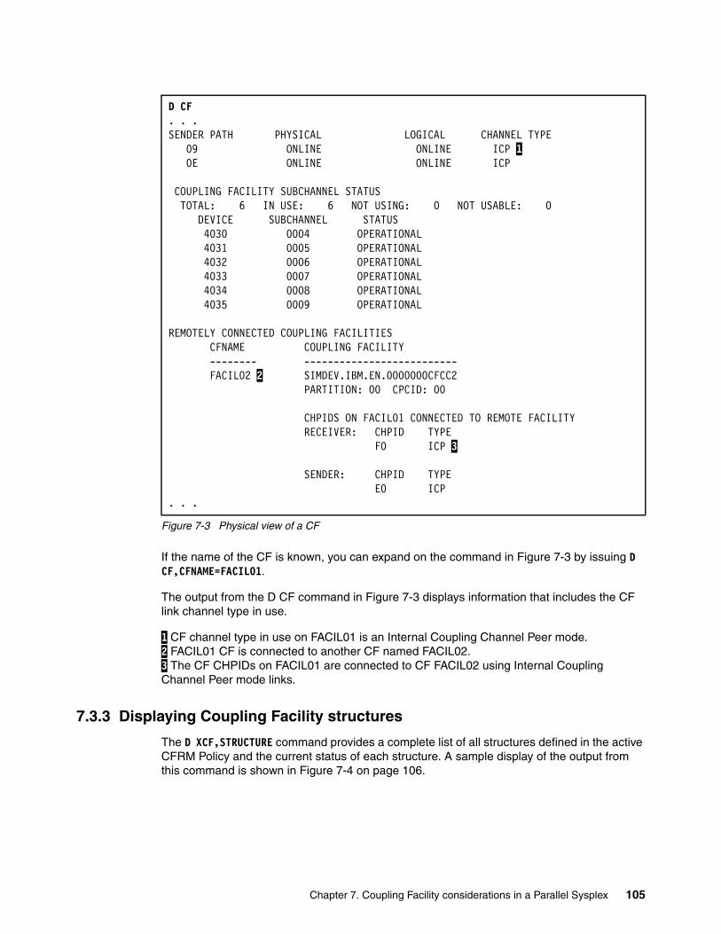
Figure 7-3 Physical view of a CF
If the name of the CF is known, you can expand on the command in Figure 7-3 by issuing D CF,CFNAME=FACIL01.
The output from the D CF command in Figure 7-3 displays information that includes the CF link channel type in use.
1 CF channel type in use on FACIL01 is an Internal Coupling Channel Peer mode. 2 FACIL01 CF is connected to another CF named FACIL02. 3 The CF CHPIDs on FACIL01 are connected to CF FACIL02 using Internal Coupling Channel Peer mode links.
7.3.3 Displaying Coupling Facility structures
The D XCF,STRUCTURE command provides a complete list of all structures defined in the active CFRM Policy and the current status of each structure. A sample display of the output from this command is shown in Figure 7-4 on page 106.
D CF. . .SENDER PATH PHYSICAL LOGICAL CHANNEL TYPE 09 ONLINE ONLINE ICP 1 0E ONLINE ONLINE ICP COUPLING FACILITY SUBCHANNEL STATUS TOTAL: 6 IN USE: 6 NOT USING: 0 NOT USABLE: 0 DEVICE SUBCHANNEL STATUS 4030 0004 OPERATIONAL 4031 0005 OPERATIONAL 4032 0006 OPERATIONAL 4033 0007 OPERATIONAL 4034 0008 OPERATIONAL 4035 0009 OPERATIONAL REMOTELY CONNECTED COUPLING FACILITIES CFNAME COUPLING FACILITY -------- -------------------------- FACIL02 2 SIMDEV.IBM.EN.0000000CFCC2 PARTITION: 00 CPCID: 00 CHPIDS ON FACIL01 CONNECTED TO REMOTE FACILITY RECEIVER: CHPID TYPE F0 ICP 3 SENDER: CHPID TYPE E0 ICP . . .
Chapter 7. Coupling Facility considerations in a Parallel Sysplex 105

Figure 7-4 Display of all CF structures
1 DFHCFLS_#@$CFDT1 was allocated at 01:47:27 on 06/21/2007 and is a List structure. 2 IRRXCF00_B001 was allocated at 21:59:18 on 06/22/2007 and is a Cache structure. 3 D#S#_LOCK1 was allocated at 03:32:17 on 06/20/2007 and is a Lock structure.
To display the structures that are currently defined to a particular CF, issue the MVS D XCF,CF,CFNAME=cfname command, where cfname is the name of the CF; see Figure 7-5 on page 107.
D XCF,STR IXC359I 20.05.03 DISPLAY XCF 643 STRNAME ALLOCATION TIME STATUS TYPE CIC_DFHLOG_001 -- -- NOT ALLOCATED CIC_DFHSHUNT_001 -- -- NOT ALLOCATED CIC_GENERAL_001 -- -- NOT ALLOCATED D#$#_GBP0 -- -- NOT ALLOCATED D#$#_GBP1 -- -- NOT ALLOCATED D#$#_GBP32K -- -- NOT ALLOCATED D#$#_GBP32K1 -- -- NOT ALLOCATED D#$#_LOCK1 06/20/2007 03:32:17 ALLOCATED (NEW)3 LOCK DUPLEXING REBUILD METHOD: SYSTEM-MANAGED PHASE: DUPLEX ESTABLISHED D#$#_LOCK1 06/20/2007 03:32:15 ALLOCATED (OLD) LOCK DUPLEXING REBUILD D#$#_SCA 06/20/2007 03:32:12 ALLOCATED (NEW) LIST DUPLEXING REBUILD METHOD: SYSTEM-MANAGED PHASE: DUPLEX ESTABLISHED D#$#_SCA 06/20/2007 03:32:10 ALLOCATED (OLD) LIST DUPLEXING REBUILD DFHCFLS_#@$CFDT1 06/21/2007 01:47:27 ALLOCATED 1 LIST DFHNCLS_#@$CNCS1 06/21/2007 01:47:24 ALLOCATED LIST DFHXQLS_#@$STOR1 06/21/2007 01:47:22 ALLOCATED LIST IRRXCF00_B001 06/22/2007 21:59:18 ALLOCATED 2 CACHE IRRXCF00_P001 06/22/2007 21:59:17 ALLOCATED CACHE . . .
106 IBM z/OS Parallel Sysplex Operational Scenarios
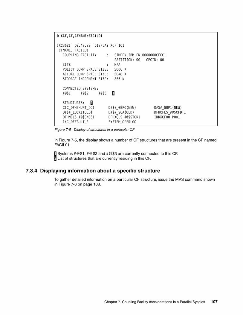
Figure 7-5 Display of structures in a particular CF
In Figure 7-5, the display shows a number of CF structures that are present in the CF named FACIL01.
1 Systems #@$1, #@$2 and #@$3 are currently connected to this CF. 2 List of structures that are currently residing in this CF.
7.3.4 Displaying information about a specific structure
To gather detailed information on a particular CF structure, issue the MVS command shown in Figure 7-6 on page 108.
D XCF,CF,CFNAME=FACIL01
IXC362I 02.49.29 DISPLAY XCF 101 CFNAME: FACIL01 COUPLING FACILITY : SIMDEV.IBM.EN.0000000CFCC1 PARTITION: 00 CPCID: 00 SITE : N/A POLICY DUMP SPACE SIZE: 2000 K ACTUAL DUMP SPACE SIZE: 2048 K STORAGE INCREMENT SIZE: 256 K CONNECTED SYSTEMS: #@$1 #@$2 #@$3 1 STRUCTURES: 2 CIC_DFHSHUNT_001 D#$#_GBP0(NEW) D#$#_GBP1(NEW) D#$#_LOCK1(OLD) D#$#_SCA(OLD) DFHCFLS_#@$CFDT1 DFHNCLS_#@$CNCS1 DFHXQLS_#@$STOR1 IRRXCF00_P001 IXC_DEFAULT_2 SYSTEM_OPERLOG
Chapter 7. Coupling Facility considerations in a Parallel Sysplex 107
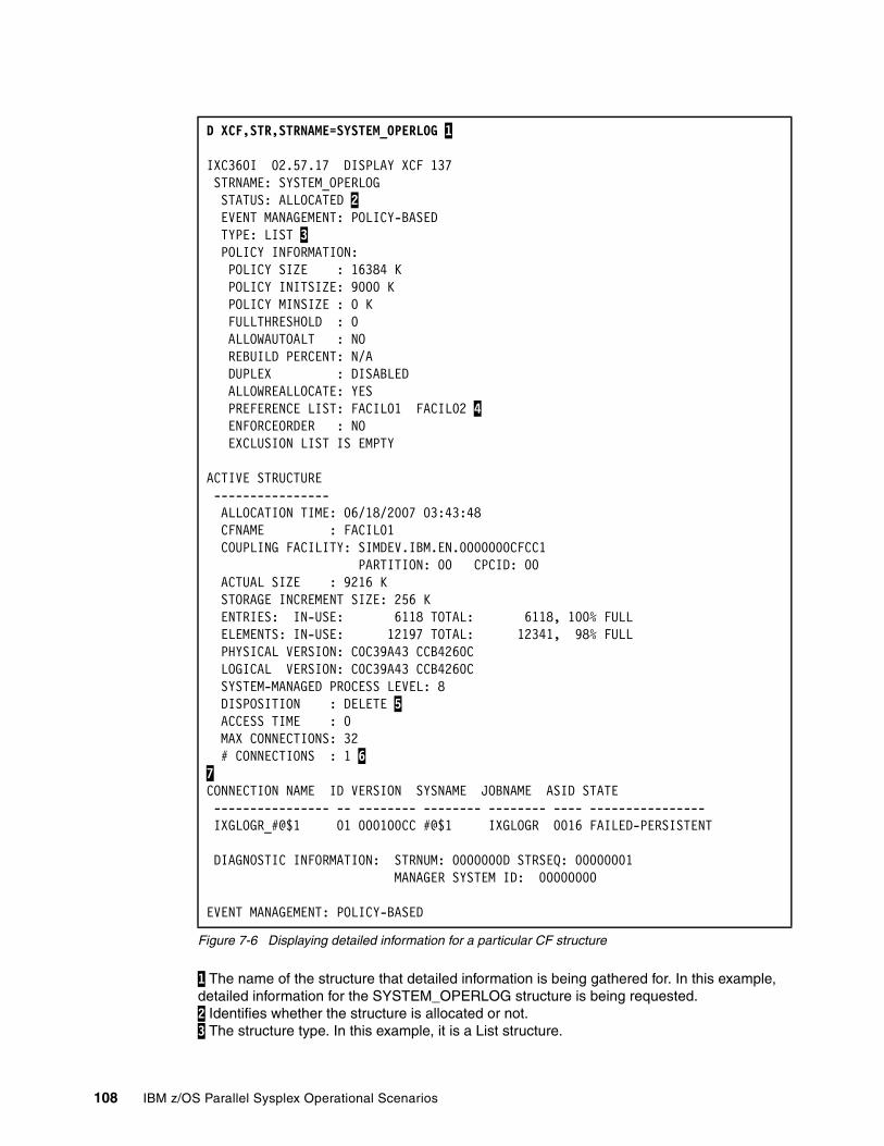
Figure 7-6 Displaying detailed information for a particular CF structure
1 The name of the structure that detailed information is being gathered for. In this example, detailed information for the SYSTEM_OPERLOG structure is being requested. 2 Identifies whether the structure is allocated or not. 3 The structure type. In this example, it is a List structure.
D XCF,STR,STRNAME=SYSTEM_OPERLOG 1
IXC360I 02.57.17 DISPLAY XCF 137 STRNAME: SYSTEM_OPERLOG STATUS: ALLOCATED 2 EVENT MANAGEMENT: POLICY-BASED TYPE: LIST 3 POLICY INFORMATION: POLICY SIZE : 16384 K POLICY INITSIZE: 9000 K POLICY MINSIZE : 0 K FULLTHRESHOLD : 0 ALLOWAUTOALT : NO REBUILD PERCENT: N/A DUPLEX : DISABLED ALLOWREALLOCATE: YES PREFERENCE LIST: FACIL01 FACIL02 4 ENFORCEORDER : NO EXCLUSION LIST IS EMPTY
ACTIVE STRUCTURE ---------------- ALLOCATION TIME: 06/18/2007 03:43:48 CFNAME : FACIL01 COUPLING FACILITY: SIMDEV.IBM.EN.0000000CFCC1 PARTITION: 00 CPCID: 00 ACTUAL SIZE : 9216 K STORAGE INCREMENT SIZE: 256 K ENTRIES: IN-USE: 6118 TOTAL: 6118, 100% FULL ELEMENTS: IN-USE: 12197 TOTAL: 12341, 98% FULL PHYSICAL VERSION: C0C39A43 CCB4260C LOGICAL VERSION: C0C39A43 CCB4260C SYSTEM-MANAGED PROCESS LEVEL: 8 DISPOSITION : DELETE 5 ACCESS TIME : 0 MAX CONNECTIONS: 32 # CONNECTIONS : 1 67 CONNECTION NAME ID VERSION SYSNAME JOBNAME ASID STATE ---------------- -- -------- -------- -------- ---- ---------------- IXGLOGR_#@$1 01 000100CC #@$1 IXGLOGR 0016 FAILED-PERSISTENT DIAGNOSTIC INFORMATION: STRNUM: 0000000D STRSEQ: 00000001 MANAGER SYSTEM ID: 00000000 EVENT MANAGEMENT: POLICY-BASED
108 IBM z/OS Parallel Sysplex Operational Scenarios
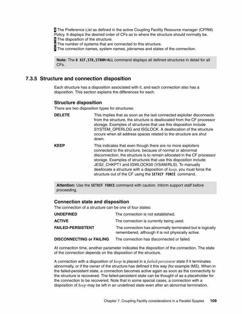
4 The Preference List as defined in the active Coupling Facility Resource manager (CFRM) Policy. It displays the desired order of CFs as to where the structure should normally be. 5 The disposition of the structure. 6 The number of systems that are connected to this structure. 7 The connection names, system names, jobnames and states of the connection.
7.3.5 Structure and connection disposition
Each structure has a disposition associated with it, and each connection also has a disposition. This section explains the differences for each.
Structure dispositionThere are two disposition types for structures:
DELETE This implies that as soon as the last connected exploiter disconnects from the structure, the structure is deallocated from the CF processor storage. Examples of structures that use this disposition include SYSTEM_OPERLOG and ISGLOCK. A deallocation of the structure occurs when all address spaces related to the structure are shut down.
KEEP This indicates that even though there are no more exploiters connected to the structure, because of normal or abnormal disconnection, the structure is to remain allocated in the CF processor storage. Examples of structures that use this disposition include JES2_CHKPT1 and IGWLOCK00 (VSAM/RLS). To manually deallocate a structure with a disposition of keep, you must force the structure out of the CF using the SETXCF FORCE command.
Connection state and dispositionThe connection of a structure can be one of four states:
UNDEFINED The connection is not established.
ACTIVE The connection is currently being used.
FAILED-PERSISTENT The connection has abnormally terminated but is logically remembered, although it is not physically active.
DISCONNECTING or FAILING The connection has disconnected or failed.
At connection time, another parameter indicates the disposition of the connection. The state of the connection depends on the disposition of the structure.
A connection with a disposition of keep is placed in a failed-persistent state if it terminates abnormally, or if the owner of the structure has defined it this way (for example IMS). When in the failed-persistent state, a connection becomes active again as soon as the connectivity to the structure is recovered. The failed-persistent state can be thought of as a placeholder for the connection to be recovered. Note that in some special cases, a connection with a disposition of keep may be left in an undefined state even after an abnormal termination.
Note: The D XCF,STR,STRNM=ALL command displays all defined structures in detail for all CFs.
Attention: Use the SETXCF FORCE command with caution. Inform support staff before proceeding.
Chapter 7. Coupling Facility considerations in a Parallel Sysplex 109

A connection with a disposition of delete is placed in an undefined state when it terminates normally. When the connectivity to the structure is recovered, the exploiter must establish a new connection.
Connections can be displayed by using the DISPLAY XCF,STRUCTURE command. For more information about displaying connection attributes, see 7.3.6, “Displaying connection attributes” on page 110.
7.3.6 Displaying connection attributes
The DISPLAY XCF,STRUCTURE,STRNM=strname,CONNM=connm command can be used to display connection attributes. To identify the connection name, we will issue the MVS command to display the required structure.
In the example in Figure 7-7 on page 111, we use the SYSTEM_OPERLOG structure.
110 IBM z/OS Parallel Sysplex Operational Scenarios
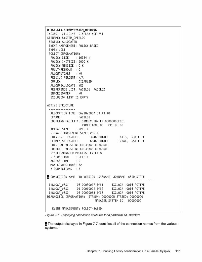
Figure 7-7 Displaying connection attributes for a particular CF structure
1 The output displayed in Figure 7-7 identifies all of the connection names from the various systems.
D XCF,STR,STRNM=SYSTEM_OPERLOG IXC360I 21.10.43 DISPLAY XCF 741 STRNAME: SYSTEM_OPERLOG STATUS: ALLOCATED EVENT MANAGEMENT: POLICY-BASED TYPE: LIST POLICY INFORMATION: POLICY SIZE : 16384 K POLICY INITSIZE: 9000 K POLICY MINSIZE : 0 K FULLTHRESHOLD : 0 ALLOWAUTOALT : NO REBUILD PERCENT: N/A DUPLEX : DISABLED ALLOWREALLOCATE: YES PREFERENCE LIST: FACIL01 FACIL02 ENFORCEORDER : NO EXCLUSION LIST IS EMPTY ACTIVE STRUCTURE ---------------- ALLOCATION TIME: 06/18/2007 03:43:48 CFNAME : FACIL01 COUPLING FACILITY: SIMDEV.IBM.EN.0000000CFCC1 PARTITION: 00 CPCID: 00 ACTUAL SIZE : 9216 K STORAGE INCREMENT SIZE: 256 K ENTRIES: IN-USE: 3246 TOTAL: 6118, 53% FULL ELEMENTS: IN-USE: 6846 TOTAL: 12341, 55% FULL PHYSICAL VERSION: C0C39A43 CCB4260C LOGICAL VERSION: C0C39A43 CCB4260C SYSTEM-MANAGED PROCESS LEVEL: 8 DISPOSITION : DELETE ACCESS TIME : 0 MAX CONNECTIONS: 32 # CONNECTIONS : 3 1 CONNECTION NAME ID VERSION SYSNAME JOBNAME ASID STATE ---------------- -- -------- -------- -------- ---- ------------ IXGLOGR_#@$1 03 00030077 #@$1 IXGLOGR 0016 ACTIVE IXGLOGR_#@$2 01 000100CE #@$2 IXGLOGR 0016 ACTIVE IXGLOGR_#@$3 02 00020065 #@$3 IXGLOGR 0016 ACTIVE DIAGNOSTIC INFORMATION: STRNUM: 0000000D STRSEQ: 00000000 MANAGER SYSTEM ID: 00000000 EVENT MANAGEMENT: POLICY-BASED
Chapter 7. Coupling Facility considerations in a Parallel Sysplex 111
Now that the connection names have been identified for the SYSTEM_OPERLOG structure, we can display the individual connection attributes for the structure. In this example, we display the ConnectionName from our system #@$3.
Figure 7-8 Displaying connection name details for a particular CF structure
1 The version of this connection. This is needed to distinguish it from other connections with the same name on the same system for the same jobname; this was done, for example, after a connection failure that was recovered. 2 This connection was done for the jobname IXGLOGR. 3 The connection is active. 4 The connection IXGLOGR_#@$3 has a connection disposition of KEEP.
5 The connection supports REBUILD. 6 The connection supports ALTER.
7.4 Structure duplexing
Not all CF exploiters provide the ability to recover from a structure failure. For those that do, certain types of structure failures require disruptive recovery processes. Recovery from a structure failure can be time-consuming, even for exploiters that provide recovery support. To address these concerns, structure duplexing is used.
D XCF,STR,STRNM=SYSTEM_OPERLOG,CONNM=IXGLOGR_#@$3 ...CONNECTION NAME : IXGLOGR_#@$3 ID : 02 VERSION : 00020065 1 CONNECT DATA : 00000001 00000000 SYSNAME : #@$3 JOBNAME : IXGLOGR 2 ASID : 0016 STATE : ACTIVE 3 FAILURE ISOLATED FROM CF CONNECT LEVEL : 00000000 00000000 INFO LEVEL : 01 CFLEVEL REQ : 00000001 NONVOLATILE REQ : YES CONDISP : KEEP 4 ALLOW REBUILD : YES 5 ALLOW DUPREBUILD: NO ALLOW AUTO : YES SUSPEND : YES ALLOW ALTER : YES 6 USER ALLOW RATIO: YES USER MINENTRY : 10 USER MINELEMENT : 10 USER MINEMC : 25 DIAGNOSTIC INFORMATION: STRNUM: 0000000D STRSEQ: 00000000 MANAGER SYSTEM ID: 00000000 EVENT MANAGEMENT: POLICY-BASED
112 IBM z/OS Parallel Sysplex Operational Scenarios
There are two types of structure duplexing:
� User-managed duplexing� System-managed duplexing
User-managed duplexing is only used by DB2 for its Group Buffer Pools. System-managed duplexing is available for any structure that supports system-managed processes.
7.4.1 System-managed Coupling Facility (CF) structure duplexing
System-managed CF structure duplexing is designed to provide a general purpose, hardware- assisted mechanism for duplexing CF structure data. This can provide a robust recovery mechanism for failures, such as a loss of a single structure or CF, or loss of connectivity to a single CF, through rapid failover to the other structure instance of the duplex pair.
Benefits of CF duplexing include:
� Availability� Manageability and usability� Configuration benefits (failure isolation)
With system-managed CF structure duplexing, two instances of the structure exist, one on each of the CFs. This eliminates the single point of failure when a data sharing structure is on the same server as one of its connectors.
Figure 7-9 on page 114 depicts how a request to a system-managed duplexed structure is processed.
� A request is sent to XES from the application or subsystem that is connected to a duplexed structure. The exploiter does not need to know if the structure is duplex or not.
� XES sends requests 2a and 2b separately to the primary and secondary structures in the CF. XES will make both either synchronous or asynchronous.
� Before the request is processed by the CFs, a synchronization point is taken between the two CFs, 3a and 3b.
� The request is then executed by each CF.
� After the request is performed, a synchronization point is taken between the CFs again.
� The result of the request is returned from each CF to XES. These requests, 6a and 6b, are checked for consistency.
� Finally, the result is returned to the exploiter.
Note: User-managed duplexing of DB2 group buffer pools does not operate this way.
Note: In user-managed duplexing mode, the request to the secondary structure is always asynchronous.
Chapter 7. Coupling Facility considerations in a Parallel Sysplex 113
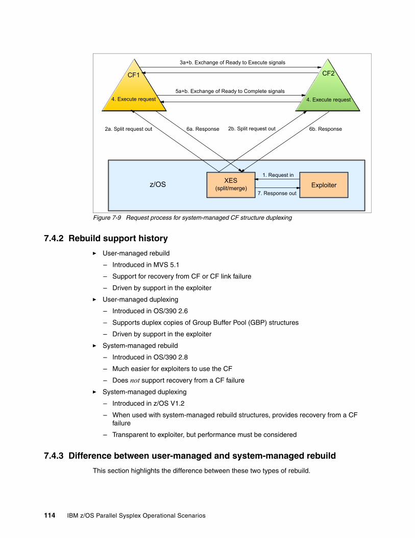
Figure 7-9 Request process for system-managed CF structure duplexing
7.4.2 Rebuild support history
� User-managed rebuild
– Introduced in MVS 5.1
– Support for recovery from CF or CF link failure
– Driven by support in the exploiter
� User-managed duplexing
– Introduced in OS/390 2.6
– Supports duplex copies of Group Buffer Pool (GBP) structures
– Driven by support in the exploiter
� System-managed rebuild
– Introduced in OS/390 2.8
– Much easier for exploiters to use the CF
– Does not support recovery from a CF failure
� System-managed duplexing
– Introduced in z/OS V1.2
– When used with system-managed rebuild structures, provides recovery from a CF failure
– Transparent to exploiter, but performance must be considered
7.4.3 Difference between user-managed and system-managed rebuild
This section highlights the difference between these two types of rebuild.
CF1 CF2
XES(split/merge)z/OS
4. Execute request 4. Execute request
3a+b. Exchange of Ready to Execute signals
5a+b. Exchange of Ready to Complete signals
2a. Split request out 6a. Response 6b. Response
Exploiter1. Request in
7. Response out
2b. Split request out
114 IBM z/OS Parallel Sysplex Operational Scenarios
User-managed rebuild:
� It involves complex programming to ensure structure connectors communicate with each other and XES to move the structure contents from one CF to another.
� It requires that 12 specific events must be catered for, as well as handling error and out-of-sequence situations.
� The level of complex programming can be time-consuming, expensive, and error-prone.
� The structure can only be moved to another CF if there is still one connector active.
� Each exploiter of a CF structure must design and code its own solution. Therefore, some exploiters do not provide rebuild capability (for example, JES2).
� It leads to complex and differing operational procedures to handle planned and unplanned CF outages.
System-managed rebuild:
� It removes most of the complexity from the applications.
� The actual movement of structure contents is handled by XES. This means that every structure that supports system-managed rebuild is handled consistently.
� Failure and out-of-sequence events are handled by XES.
� Rebuild support is easier for CF exploiters.
� It provides consistent operational procedures.
� It can rebuild a structure when there are no active connectors.
� It provides support for planned CF reconfigurations.
� It is not for recovery scenarios.
7.4.4 Enabling system-managed CF structure duplexing
The relevant structure definitions need to be updated in a new CFRM policy and activated to include the DUPLEX keyword.
The updated CFRM Policy will then need to be activated using the command SETXCF START,POL,POLNM=policyname,TYPE=CFRM.
Additional information can be found in the IBM Technical Paper titled “System -Managed CF Structure Duplexing”. It is available at the following URL:
http://www.ibm.com/servers/eserver/zseries/library/techpapers/gm130103.html
The CF duplexing function for a structure can be started and stopped by MVS commands. There are two ways to start duplexing:
� Activate a new CFRM policy with DUPLEX(ENABLED) keyword for the structure.
If the old structure is currently allocated, then z/OS will automatically initiate the process to establish duplexing as soon as you activate the policy.
If the structure is not currently allocated, then the duplexing process will be initiated automatically when the structure is allocated.
Note: Although there is value in CF duplexing, IBM does not recommend its use in all situations, nor should it necessarily be used in every environment for the structures that support it.
Chapter 7. Coupling Facility considerations in a Parallel Sysplex 115
� Activate a new CFRM policy with DUPLEX(ALLOWED) keyword for the structure.
This method allows the structures to be duplexed; however, the duplexing must be initiated by command because z/OS will not automatically duplex the structure.
Duplexing can then be initiated using the SETXCF START,REBUILD,DUPLEX command or programmatically via the IXLREBLD STARTDUPLEX programming interface.
Duplexing can be manually stopped by using the SETXCF STOP,REBUILD,DUPLEX command or programmatically via the IXLREBLD STOPDUPLEX programming interface. When you need to stop duplexing structures, you must first decide which is to remain as the surviving simplex structure.
You can also stop duplexing of a structure in a particular CF by issuing the command SETXCF STOP,REBUILD,DUPLEX,CFNAME=cfname
For further information about each system command of CF Duplexing, including SETXCF, refer to z/OS MVS System Commands, SA22-7627.
7.4.5 Identifying which structures are duplexed
To identify which structures are defined in the active CFRM Policy as being system-managed CF structure duplexed, issue the MVS D XCF,STR,STRNM=strname command that is shown in Figure 7-10 on page 117.
116 IBM z/OS Parallel Sysplex Operational Scenarios
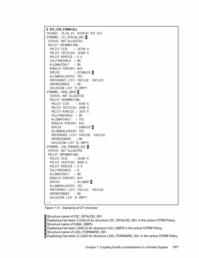
Figure 7-10 Displaying all CF structures
1 Structure name of CIC_DFHLOG_001. 2 Duplexing has been DISABLED for structure CIC_DFHLOG_001 in the active CFRM Policy. 3 Structure name of D#$#_GBP0. 4 Duplexing has been ENABLED for structure D#$#_GBP0 in the active CFRM Policy. 5 Structure name of LOG_FORWARD_001. 6 Duplexing has been ALLOWED for structure LOG_FORWARD_001 in the active CFRM Policy.
D XCF,STR,STRNM=ALL IXC360I 19.01.23 DISPLAY XCF 013 STRNAME: CIC_DFHLOG_001 1 STATUS: NOT ALLOCATED POLICY INFORMATION: POLICY SIZE : 32756 K POLICY INITSIZE: 16384 K POLICY MINSIZE : 0 K FULLTHRESHOLD : 80 ALLOWAUTOALT : NO REBUILD PERCENT: N/A DUPLEX : DISABLED 2 ALLOWREALLOCATE: YES PREFERENCE LIST: FACIL02 FACIL01 ENFORCEORDER : NO EXCLUSION LIST IS EMPTY STRNAME: D#$#_GBP0 3 STATUS: NOT ALLOCATED POLICY INFORMATION: POLICY SIZE : 8192 K POLICY INITSIZE: 4096 K POLICY MINSIZE : 3072 K FULLTHRESHOLD : 80 ALLOWAUTOALT : YES REBUILD PERCENT: N/A DUPLEX : ENABLED 4 ALLOWREALLOCATE: YES PREFERENCE LIST: FACIL02 FACIL01 ENFORCEORDER : NO EXCLUSION LIST IS EMPTY STRNAME: LOG_FORWARD_001 5 STATUS: NOT ALLOCATED POLICY INFORMATION: POLICY SIZE : 16384 K POLICY INITSIZE: 9000 K POLICY MINSIZE : 0 K FULLTHRESHOLD : 0 ALLOWAUTOALT : NO REBUILD PERCENT: N/A DUPLEX : ALLOWED 6 ALLOWREALLOCATE: YES PREFERENCE LIST: FACIL01 FACIL02 ENFORCEORDER : NO EXCLUSION LIST IS EMPTY ...
Chapter 7. Coupling Facility considerations in a Parallel Sysplex 117
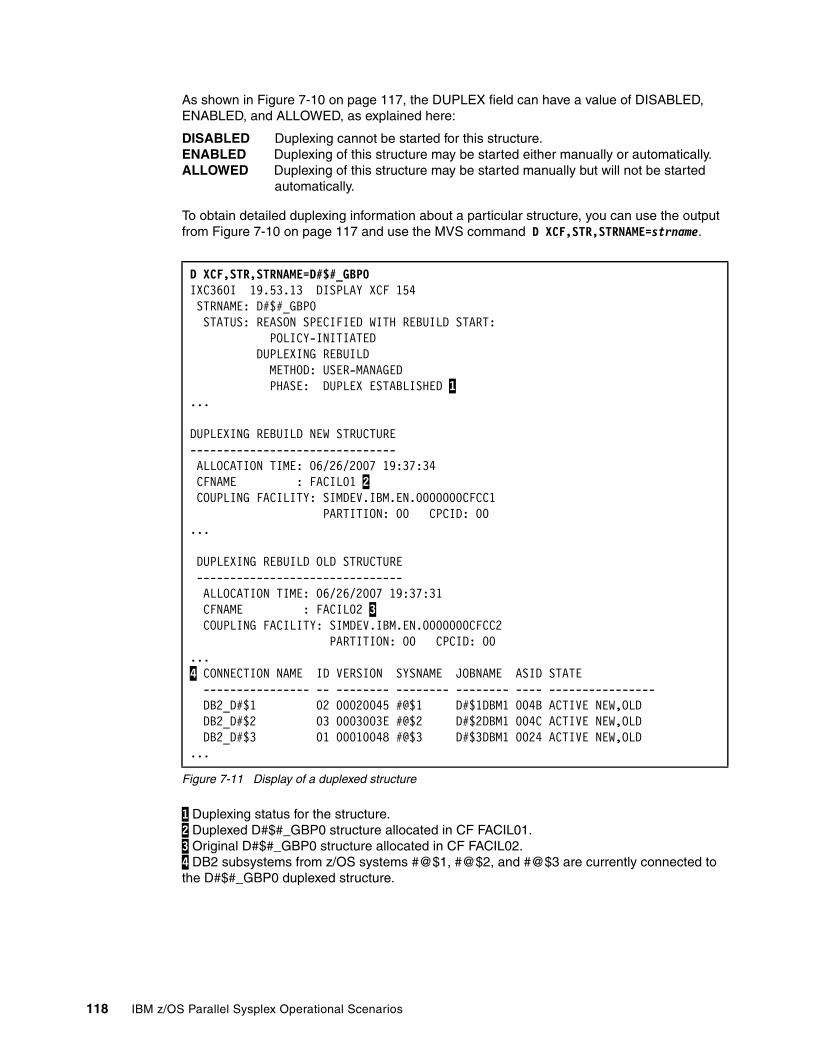
As shown in Figure 7-10 on page 117, the DUPLEX field can have a value of DISABLED, ENABLED, and ALLOWED, as explained here:
DISABLED Duplexing cannot be started for this structure.ENABLED Duplexing of this structure may be started either manually or automatically.ALLOWED Duplexing of this structure may be started manually but will not be started
automatically.
To obtain detailed duplexing information about a particular structure, you can use the output from Figure 7-10 on page 117 and use the MVS command D XCF,STR,STRNAME=strname.
Figure 7-11 Display of a duplexed structure
1 Duplexing status for the structure. 2 Duplexed D#$#_GBP0 structure allocated in CF FACIL01. 3 Original D#$#_GBP0 structure allocated in CF FACIL02. 4 DB2 subsystems from z/OS systems #@$1, #@$2, and #@$3 are currently connected to the D#$#_GBP0 duplexed structure.
D XCF,STR,STRNAME=D#$#_GBP0IXC360I 19.53.13 DISPLAY XCF 154 STRNAME: D#$#_GBP0 STATUS: REASON SPECIFIED WITH REBUILD START: POLICY-INITIATED DUPLEXING REBUILD METHOD: USER-MANAGED PHASE: DUPLEX ESTABLISHED 1...
DUPLEXING REBUILD NEW STRUCTURE ------------------------------- ALLOCATION TIME: 06/26/2007 19:37:34 CFNAME : FACIL01 2 COUPLING FACILITY: SIMDEV.IBM.EN.0000000CFCC1 PARTITION: 00 CPCID: 00 ...
DUPLEXING REBUILD OLD STRUCTURE ------------------------------- ALLOCATION TIME: 06/26/2007 19:37:31 CFNAME : FACIL02 3 COUPLING FACILITY: SIMDEV.IBM.EN.0000000CFCC2 PARTITION: 00 CPCID: 00 ...4 CONNECTION NAME ID VERSION SYSNAME JOBNAME ASID STATE ---------------- -- -------- -------- -------- ---- ---------------- DB2_D#$1 02 00020045 #@$1 D#$1DBM1 004B ACTIVE NEW,OLD DB2_D#$2 03 0003003E #@$2 D#$2DBM1 004C ACTIVE NEW,OLD DB2_D#$3 01 00010048 #@$3 D#$3DBM1 0024 ACTIVE NEW,OLD ...
118 IBM z/OS Parallel Sysplex Operational Scenarios
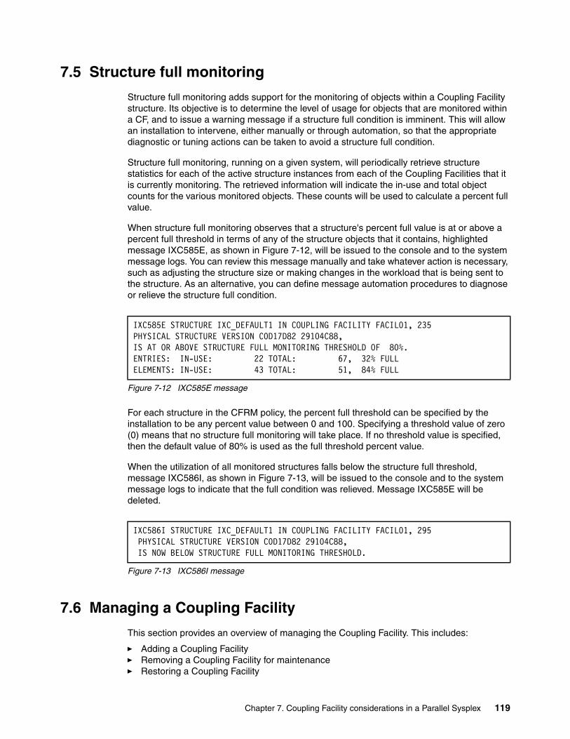
7.5 Structure full monitoring
Structure full monitoring adds support for the monitoring of objects within a Coupling Facility structure. Its objective is to determine the level of usage for objects that are monitored within a CF, and to issue a warning message if a structure full condition is imminent. This will allow an installation to intervene, either manually or through automation, so that the appropriate diagnostic or tuning actions can be taken to avoid a structure full condition.
Structure full monitoring, running on a given system, will periodically retrieve structure statistics for each of the active structure instances from each of the Coupling Facilities that it is currently monitoring. The retrieved information will indicate the in-use and total object counts for the various monitored objects. These counts will be used to calculate a percent full value.
When structure full monitoring observes that a structure's percent full value is at or above a percent full threshold in terms of any of the structure objects that it contains, highlighted message IXC585E, as shown in Figure 7-12, will be issued to the console and to the system message logs. You can review this message manually and take whatever action is necessary, such as adjusting the structure size or making changes in the workload that is being sent to the structure. As an alternative, you can define message automation procedures to diagnose or relieve the structure full condition.
Figure 7-12 IXC585E message
For each structure in the CFRM policy, the percent full threshold can be specified by the installation to be any percent value between 0 and 100. Specifying a threshold value of zero (0) means that no structure full monitoring will take place. If no threshold value is specified, then the default value of 80% is used as the full threshold percent value.
When the utilization of all monitored structures falls below the structure full threshold, message IXC586I, as shown in Figure 7-13, will be issued to the console and to the system message logs to indicate that the full condition was relieved. Message IXC585E will be deleted.
Figure 7-13 IXC586I message
7.6 Managing a Coupling Facility
This section provides an overview of managing the Coupling Facility. This includes:
� Adding a Coupling Facility� Removing a Coupling Facility for maintenance� Restoring a Coupling Facility
IXC585E STRUCTURE IXC_DEFAULT1 IN COUPLING FACILITY FACIL01, 235 PHYSICAL STRUCTURE VERSION C0D17D82 29104C88, IS AT OR ABOVE STRUCTURE FULL MONITORING THRESHOLD OF 80%.ENTRIES: IN-USE: 22 TOTAL: 67, 32% FULL ELEMENTS: IN-USE: 43 TOTAL: 51, 84% FULL
IXC586I STRUCTURE IXC_DEFAULT1 IN COUPLING FACILITY FACIL01, 295 PHYSICAL STRUCTURE VERSION C0D17D82 29104C88, IS NOW BELOW STRUCTURE FULL MONITORING THRESHOLD.
Chapter 7. Coupling Facility considerations in a Parallel Sysplex 119
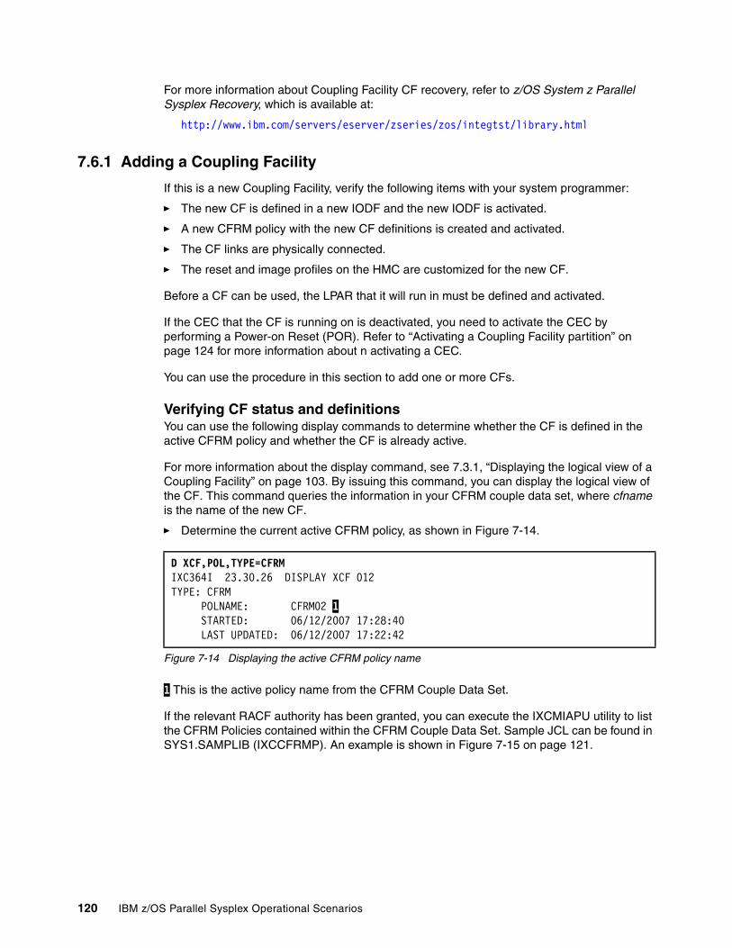
For more information about Coupling Facility CF recovery, refer to z/OS System z Parallel Sysplex Recovery, which is available at:
http://www.ibm.com/servers/eserver/zseries/zos/integtst/library.html
7.6.1 Adding a Coupling Facility
If this is a new Coupling Facility, verify the following items with your system programmer:
� The new CF is defined in a new IODF and the new IODF is activated.
� A new CFRM policy with the new CF definitions is created and activated.
� The CF links are physically connected.
� The reset and image profiles on the HMC are customized for the new CF.
Before a CF can be used, the LPAR that it will run in must be defined and activated.
If the CEC that the CF is running on is deactivated, you need to activate the CEC by performing a Power-on Reset (POR). Refer to “Activating a Coupling Facility partition” on page 124 for more information about n activating a CEC.
You can use the procedure in this section to add one or more CFs.
Verifying CF status and definitionsYou can use the following display commands to determine whether the CF is defined in the active CFRM policy and whether the CF is already active.
For more information about the display command, see 7.3.1, “Displaying the logical view of a Coupling Facility” on page 103. By issuing this command, you can display the logical view of the CF. This command queries the information in your CFRM couple data set, where cfname is the name of the new CF.
� Determine the current active CFRM policy, as shown in Figure 7-14.
Figure 7-14 Displaying the active CFRM policy name
1 This is the active policy name from the CFRM Couple Data Set.
If the relevant RACF authority has been granted, you can execute the IXCMIAPU utility to list the CFRM Policies contained within the CFRM Couple Data Set. Sample JCL can be found in SYS1.SAMPLIB (IXCCFRMP). An example is shown in Figure 7-15 on page 121.
D XCF,POL,TYPE=CFRM IXC364I 23.30.26 DISPLAY XCF 012 TYPE: CFRM POLNAME: CFRM02 1 STARTED: 06/12/2007 17:28:40 LAST UPDATED: 06/12/2007 17:22:42
120 IBM z/OS Parallel Sysplex Operational Scenarios
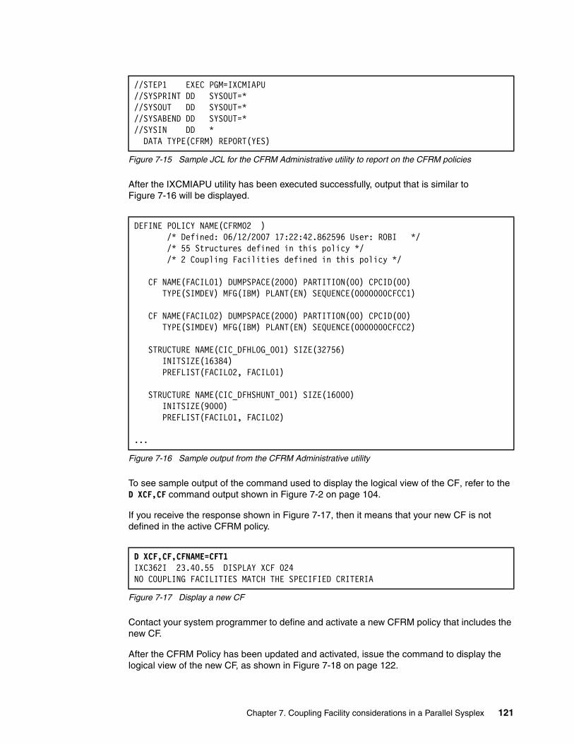
Figure 7-15 Sample JCL for the CFRM Administrative utility to report on the CFRM policies
After the IXCMIAPU utility has been executed successfully, output that is similar to Figure 7-16 will be displayed.
Figure 7-16 Sample output from the CFRM Administrative utility
To see sample output of the command used to display the logical view of the CF, refer to the D XCF,CF command output shown in Figure 7-2 on page 104.
If you receive the response shown in Figure 7-17, then it means that your new CF is not defined in the active CFRM policy.
Figure 7-17 Display a new CF
Contact your system programmer to define and activate a new CFRM policy that includes the new CF.
After the CFRM Policy has been updated and activated, issue the command to display the logical view of the new CF, as shown in Figure 7-18 on page 122.
//STEP1 EXEC PGM=IXCMIAPU //SYSPRINT DD SYSOUT=* //SYSOUT DD SYSOUT=* //SYSABEND DD SYSOUT=* //SYSIN DD * DATA TYPE(CFRM) REPORT(YES)
DEFINE POLICY NAME(CFRM02 ) /* Defined: 06/12/2007 17:22:42.862596 User: ROBI */ /* 55 Structures defined in this policy */ /* 2 Coupling Facilities defined in this policy */ CF NAME(FACIL01) DUMPSPACE(2000) PARTITION(00) CPCID(00) TYPE(SIMDEV) MFG(IBM) PLANT(EN) SEQUENCE(0000000CFCC1) CF NAME(FACIL02) DUMPSPACE(2000) PARTITION(00) CPCID(00) TYPE(SIMDEV) MFG(IBM) PLANT(EN) SEQUENCE(0000000CFCC2) STRUCTURE NAME(CIC_DFHLOG_001) SIZE(32756) INITSIZE(16384) PREFLIST(FACIL02, FACIL01) STRUCTURE NAME(CIC_DFHSHUNT_001) SIZE(16000) INITSIZE(9000) PREFLIST(FACIL01, FACIL02) ...
D XCF,CF,CFNAME=CFT1 IXC362I 23.40.55 DISPLAY XCF 024 NO COUPLING FACILITIES MATCH THE SPECIFIED CRITERIA
Chapter 7. Coupling Facility considerations in a Parallel Sysplex 121
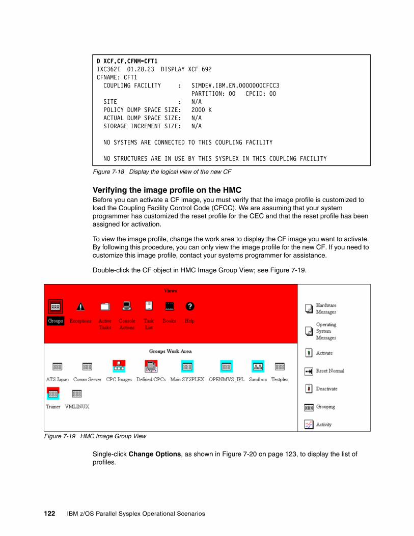
Figure 7-18 Display the logical view of the new CF
Verifying the image profile on the HMCBefore you can activate a CF image, you must verify that the image profile is customized to load the Coupling Facility Control Code (CFCC). We are assuming that your system programmer has customized the reset profile for the CEC and that the reset profile has been assigned for activation.
To view the image profile, change the work area to display the CF image you want to activate. By following this procedure, you can only view the image profile for the new CF. If you need to customize this image profile, contact your systems programmer for assistance.
Double-click the CF object in HMC Image Group View; see Figure 7-19.
Figure 7-19 HMC Image Group View
Single-click Change Options, as shown in Figure 7-20 on page 123, to display the list of profiles.
D XCF,CF,CFNM=CFT1 IXC362I 01.28.23 DISPLAY XCF 692 CFNAME: CFT1 COUPLING FACILITY : SIMDEV.IBM.EN.0000000CFCC3 PARTITION: 00 CPCID: 00 SITE : N/A POLICY DUMP SPACE SIZE: 2000 K ACTUAL DUMP SPACE SIZE: N/A STORAGE INCREMENT SIZE: N/A NO SYSTEMS ARE CONNECTED TO THIS COUPLING FACILITY NO STRUCTURES ARE IN USE BY THIS SYSPLEX IN THIS COUPLING FACILITY
122 IBM z/OS Parallel Sysplex Operational Scenarios
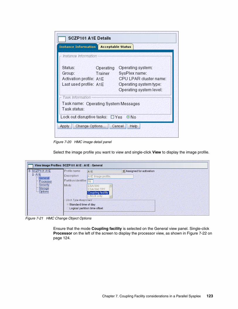
Figure 7-20 HMC image detail panel
Select the image profile you want to view and single-click View to display the image profile.
Figure 7-21 HMC Change Object Options
Ensure that the mode Coupling facility is selected on the General view panel. Single-click Processor on the left of the screen to display the processor view, as shown in Figure 7-22 on page 124.
Chapter 7. Coupling Facility considerations in a Parallel Sysplex 123
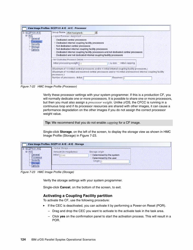
Figure 7-22 HMC Image Profile (Processor)
Verify these processor settings with your system programmer. If this is a production CF, you will normally dedicate one or more processors. It is possible to share one or more processors, but then you must also assign a processor weight. Unlike z/OS, the CFCC is running in a continuous loop and if its processor resources are shared with other images, it can cause a performance degradation on the other images if you do not assign the correct processor weight value.
Single-click Storage, on the left of the screen, to display the storage view as shown in HMC Image Profile (Storage) in Figure 7-23.
Figure 7-23 HMC Image Profile (Storage)
Verify the storage settings with your system programmer.
Single-click Cancel, on the bottom of the screen, to exit.
Activating a Coupling Facility partitionTo activate the CF, use the following procedure:
� If the CEC is deactivated, you can activate it by performing a Power-on Reset (POR).
– Drag and drop the CEC you want to activate to the activate task in the task area.
– Click yes on the confirmation panel to start the activation process. This will result in a POR.
Tip: We recommend that you do not enable capping for a CF image.
124 IBM z/OS Parallel Sysplex Operational Scenarios
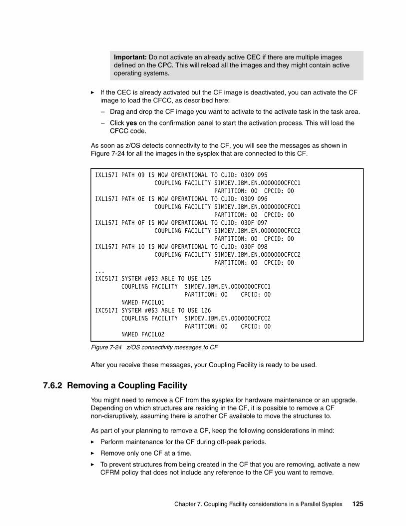
� If the CEC is already activated but the CF image is deactivated, you can activate the CF image to load the CFCC, as described here:
– Drag and drop the CF image you want to activate to the activate task in the task area.
– Click yes on the confirmation panel to start the activation process. This will load the CFCC code.
As soon as z/OS detects connectivity to the CF, you will see the messages as shown in Figure 7-24 for all the images in the sysplex that are connected to this CF.
Figure 7-24 z/OS connectivity messages to CF
After you receive these messages, your Coupling Facility is ready to be used.
7.6.2 Removing a Coupling Facility
You might need to remove a CF from the sysplex for hardware maintenance or an upgrade. Depending on which structures are residing in the CF, it is possible to remove a CF non-disruptively, assuming there is another CF available to move the structures to.
As part of your planning to remove a CF, keep the following considerations in mind:
� Perform maintenance for the CF during off-peak periods.
� Remove only one CF at a time.
� To prevent structures from being created in the CF that you are removing, activate a new CFRM policy that does not include any reference to the CF you want to remove.
Important: Do not activate an already active CEC if there are multiple images defined on the CPC. This will reload all the images and they might contain active operating systems.
IXL157I PATH 09 IS NOW OPERATIONAL TO CUID: 0309 095 COUPLING FACILITY SIMDEV.IBM.EN.0000000CFCC1 PARTITION: 00 CPCID: 00 IXL157I PATH 0E IS NOW OPERATIONAL TO CUID: 0309 096 COUPLING FACILITY SIMDEV.IBM.EN.0000000CFCC1 PARTITION: 00 CPCID: 00 IXL157I PATH 0F IS NOW OPERATIONAL TO CUID: 030F 097 COUPLING FACILITY SIMDEV.IBM.EN.0000000CFCC2 PARTITION: 00 CPCID: 00 IXL157I PATH 10 IS NOW OPERATIONAL TO CUID: 030F 098 COUPLING FACILITY SIMDEV.IBM.EN.0000000CFCC2 PARTITION: 00 CPCID: 00 ...IXC517I SYSTEM #@$3 ABLE TO USE 125 COUPLING FACILITY SIMDEV.IBM.EN.0000000CFCC1 PARTITION: 00 CPCID: 00 NAMED FACIL01 IXC517I SYSTEM #@$3 ABLE TO USE 126 COUPLING FACILITY SIMDEV.IBM.EN.0000000CFCC2 PARTITION: 00 CPCID: 00 NAMED FACIL02
Chapter 7. Coupling Facility considerations in a Parallel Sysplex 125
� Resolve failed persistent and no connector structure conditions before shutting down the CF.
� Ensure all systems in the sysplex that are currently using the structures in the CF you want to remove have connectivity to the alternate Coupling Facility.
� To allow structures to be rebuilt on an alternate CF, ensure that enough capacity, such as storage and CPU cycles, exists on the alternate CF.
Removing a Coupling Facility when multiple Coupling Facilities existTo remove a CF when multiple CFs exist in the configuration, use the following procedure.
Determine the status of the CFsSee Figure 7-25 on page 127 to display the physical view of the CFs to determine if there is enough spare storage capacity available on the target CF to move the structures.
126 IBM z/OS Parallel Sysplex Operational Scenarios
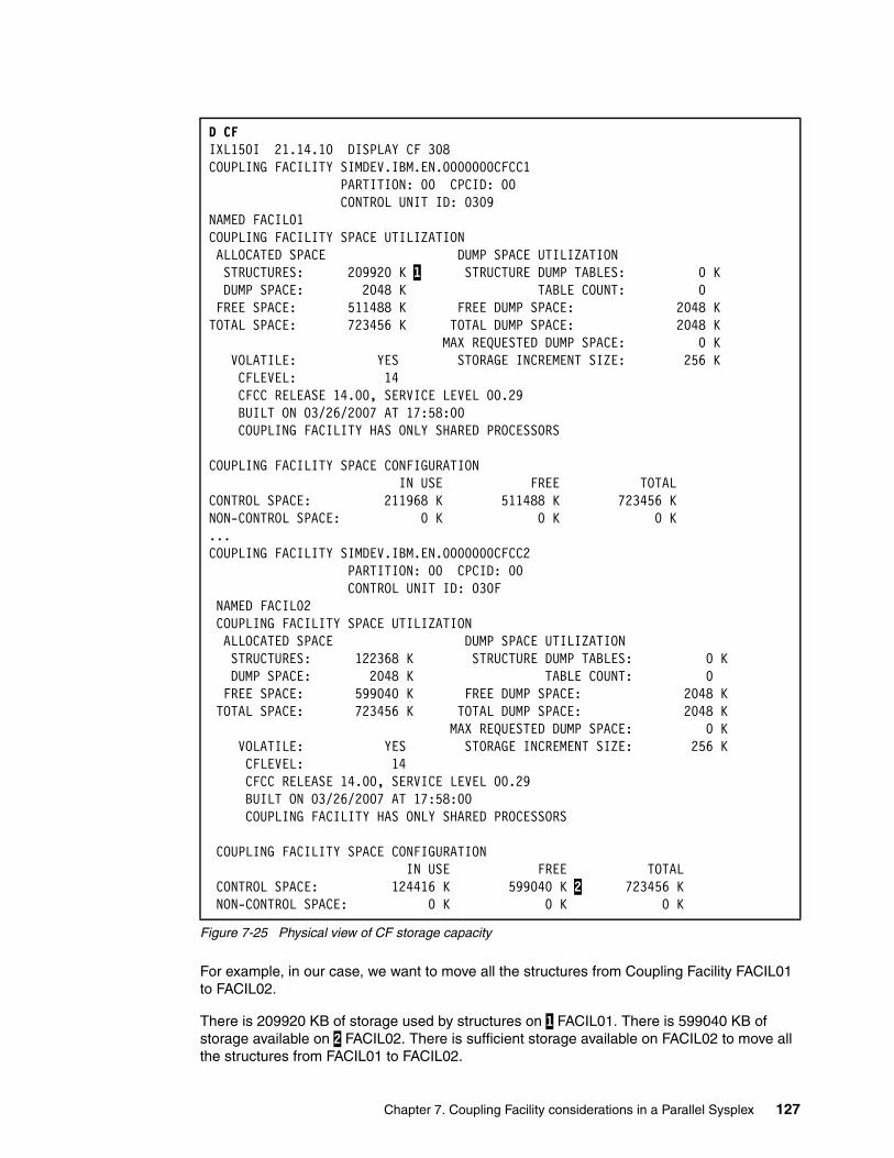
Figure 7-25 Physical view of CF storage capacity
For example, in our case, we want to move all the structures from Coupling Facility FACIL01 to FACIL02.
There is 209920 KB of storage used by structures on 1 FACIL01. There is 599040 KB of storage available on 2 FACIL02. There is sufficient storage available on FACIL02 to move all the structures from FACIL01 to FACIL02.
D CF IXL150I 21.14.10 DISPLAY CF 308 COUPLING FACILITY SIMDEV.IBM.EN.0000000CFCC1 PARTITION: 00 CPCID: 00 CONTROL UNIT ID: 0309 NAMED FACIL01 COUPLING FACILITY SPACE UTILIZATION ALLOCATED SPACE DUMP SPACE UTILIZATION STRUCTURES: 209920 K 1 STRUCTURE DUMP TABLES: 0 K DUMP SPACE: 2048 K TABLE COUNT: 0 FREE SPACE: 511488 K FREE DUMP SPACE: 2048 K TOTAL SPACE: 723456 K TOTAL DUMP SPACE: 2048 K MAX REQUESTED DUMP SPACE: 0 K VOLATILE: YES STORAGE INCREMENT SIZE: 256 K CFLEVEL: 14 CFCC RELEASE 14.00, SERVICE LEVEL 00.29 BUILT ON 03/26/2007 AT 17:58:00 COUPLING FACILITY HAS ONLY SHARED PROCESSORS COUPLING FACILITY SPACE CONFIGURATION IN USE FREE TOTAL CONTROL SPACE: 211968 K 511488 K 723456 K NON-CONTROL SPACE: 0 K 0 K 0 K ...COUPLING FACILITY SIMDEV.IBM.EN.0000000CFCC2 PARTITION: 00 CPCID: 00 CONTROL UNIT ID: 030F NAMED FACIL02 COUPLING FACILITY SPACE UTILIZATION ALLOCATED SPACE DUMP SPACE UTILIZATION STRUCTURES: 122368 K STRUCTURE DUMP TABLES: 0 K DUMP SPACE: 2048 K TABLE COUNT: 0 FREE SPACE: 599040 K FREE DUMP SPACE: 2048 K TOTAL SPACE: 723456 K TOTAL DUMP SPACE: 2048 K MAX REQUESTED DUMP SPACE: 0 K VOLATILE: YES STORAGE INCREMENT SIZE: 256 K CFLEVEL: 14 CFCC RELEASE 14.00, SERVICE LEVEL 00.29 BUILT ON 03/26/2007 AT 17:58:00 COUPLING FACILITY HAS ONLY SHARED PROCESSORS COUPLING FACILITY SPACE CONFIGURATION IN USE FREE TOTAL CONTROL SPACE: 124416 K 599040 K 2 723456 K NON-CONTROL SPACE: 0 K 0 K 0 K
Chapter 7. Coupling Facility considerations in a Parallel Sysplex 127
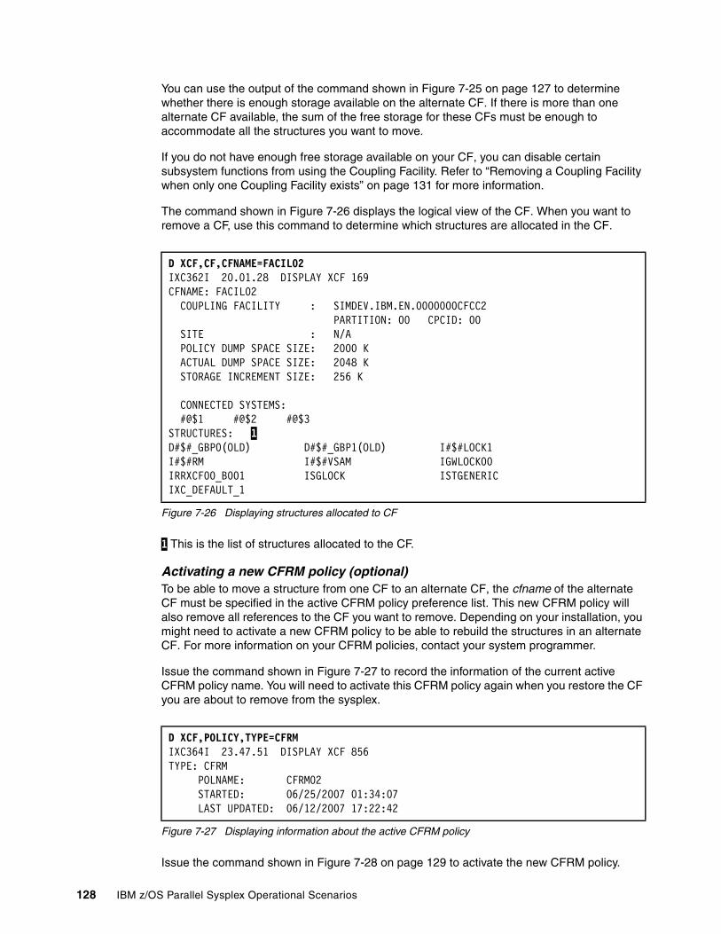
You can use the output of the command shown in Figure 7-25 on page 127 to determine whether there is enough storage available on the alternate CF. If there is more than one alternate CF available, the sum of the free storage for these CFs must be enough to accommodate all the structures you want to move.
If you do not have enough free storage available on your CF, you can disable certain subsystem functions from using the Coupling Facility. Refer to “Removing a Coupling Facility when only one Coupling Facility exists” on page 131 for more information.
The command shown in Figure 7-26 displays the logical view of the CF. When you want to remove a CF, use this command to determine which structures are allocated in the CF.
Figure 7-26 Displaying structures allocated to CF
1 This is the list of structures allocated to the CF.
Activating a new CFRM policy (optional)To be able to move a structure from one CF to an alternate CF, the cfname of the alternate CF must be specified in the active CFRM policy preference list. This new CFRM policy will also remove all references to the CF you want to remove. Depending on your installation, you might need to activate a new CFRM policy to be able to rebuild the structures in an alternate CF. For more information on your CFRM policies, contact your system programmer.
Issue the command shown in Figure 7-27 to record the information of the current active CFRM policy name. You will need to activate this CFRM policy again when you restore the CF you are about to remove from the sysplex.
Figure 7-27 Displaying information about the active CFRM policy
Issue the command shown in Figure 7-28 on page 129 to activate the new CFRM policy.
D XCF,CF,CFNAME=FACIL02 IXC362I 20.01.28 DISPLAY XCF 169 CFNAME: FACIL02 COUPLING FACILITY : SIMDEV.IBM.EN.0000000CFCC2 PARTITION: 00 CPCID: 00 SITE : N/A POLICY DUMP SPACE SIZE: 2000 K ACTUAL DUMP SPACE SIZE: 2048 K STORAGE INCREMENT SIZE: 256 K CONNECTED SYSTEMS: #@$1 #@$2 #@$3 STRUCTURES: 1 D#$#_GBP0(OLD) D#$#_GBP1(OLD) I#$#LOCK1 I#$#RM I#$#VSAM IGWLOCK00 IRRXCF00_B001 ISGLOCK ISTGENERIC IXC_DEFAULT_1
D XCF,POLICY,TYPE=CFRM IXC364I 23.47.51 DISPLAY XCF 856 TYPE: CFRM POLNAME: CFRM02 STARTED: 06/25/2007 01:34:07 LAST UPDATED: 06/12/2007 17:22:42
128 IBM z/OS Parallel Sysplex Operational Scenarios

Figure 7-28 Activate a new CFRM Policy
Use a name for the new CFRM policy that is different from the name of the original CFRM policy so that when CF maintenance is complete, the original policy can be restored.
After the command shown in Figure 7-28 has been issued, you may see the messages displayed in Figure 7-29.
Figure 7-29 Policy change pending messages
If you receive the messages shown in Figure 7-29, issue the command in Figure 7-30 to identify structures that are in a policy change pending state.
Figure 7-30 Identify structures in a policy change pending state
Moving structures to the alternate Coupling FacilityThe structures as shown in Figure 7-26 on page 128 need to be moved before the CF can be shut down. Some structures can be moved by issuing the command shown in Figure 7-31.
Figure 7-31 Rebuild a structure to another CF
Other structures must be moved by the owning subsystem (for example, the JES2 checkpoint structure). See 7.8, “Managing CF structures” on page 147, for information about moving these structures and deallocating persistent structures.
SETXCF START,POLICY,TYPE=CFRM,POLNAME=new_policy_name
IXC511I START ADMINISTRATIVE POLICY CFRM03 FOR CFRM ACCEPTED IXC512I POLICY CHANGE IN PROGRESS FOR CFRM 876 TO MAKE CFRM03 POLICY ACTIVE. 2 POLICY CHANGE(S) PENDING.
Note: When you start a new CFRM policy, the allocated structures that are affected by the new policy change enter a policy change pending state. Structures that enter a policy change pending state remain in that state until the structure is deallocated and reallocated through a rebuild. Structures that reside on CFs that are not being removed might remain in a policy change pending state until the original policy is restored.
D XCF,STR,STATUS=POLICYCHANGE
IXC359I 00.00.09 DISPLAY XCF 884 STRNAME ALLOCATION TIME STATUS TYPE IXC_DEFAULT_1 06/26/2007 22:25:22 ALLOCATED LIST POLICY CHANGE PENDING - CHANGE IXC_DEFAULT_2 06/26/2007 22:25:13 ALLOCATED LIST POLICY CHANGE PENDING - CHANGE EVENT MANAGEMENT: POLICY-BASED
SETXCF START,REBUILD,{STRNAME=strname|LOC=cfname}
Chapter 7. Coupling Facility considerations in a Parallel Sysplex 129
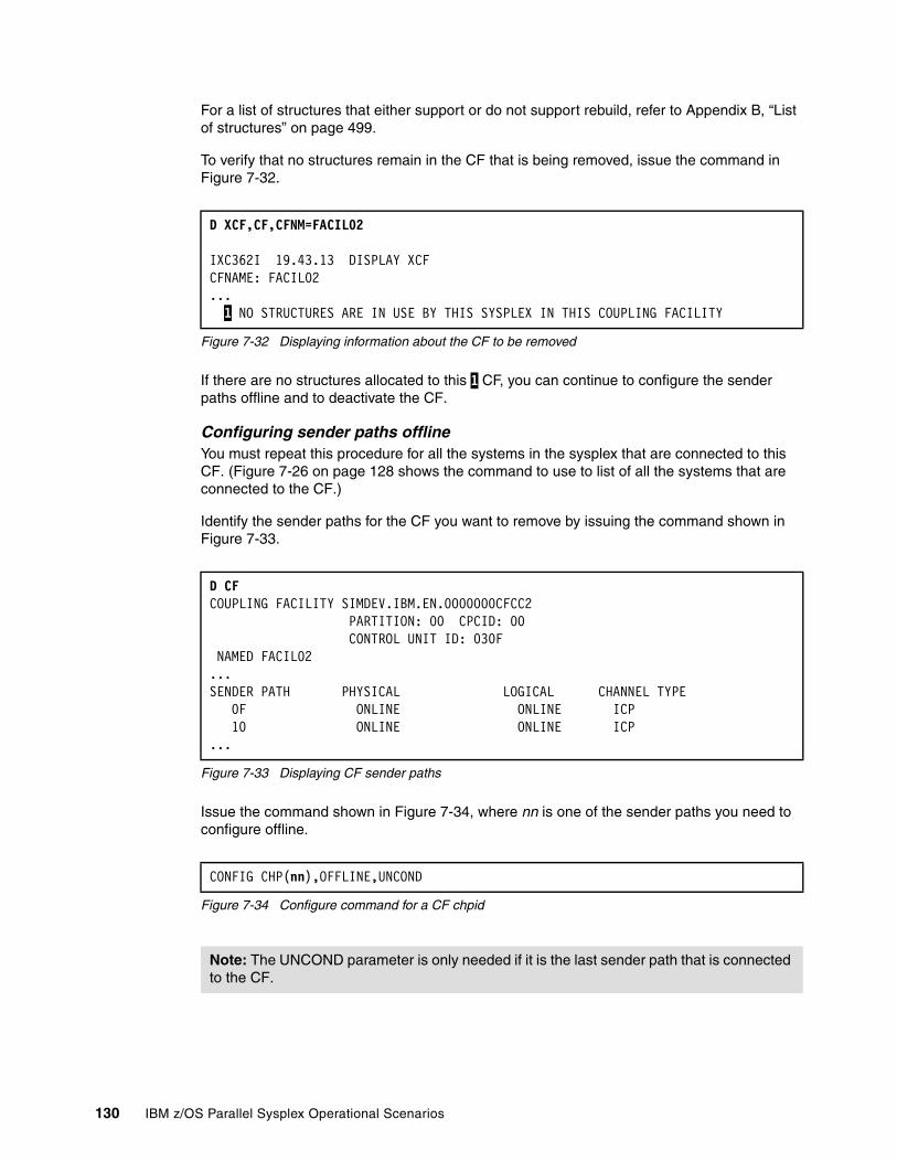
For a list of structures that either support or do not support rebuild, refer to Appendix B, “List of structures” on page 499.
To verify that no structures remain in the CF that is being removed, issue the command in Figure 7-32.
Figure 7-32 Displaying information about the CF to be removed
If there are no structures allocated to this 1 CF, you can continue to configure the sender paths offline and to deactivate the CF.
Configuring sender paths offlineYou must repeat this procedure for all the systems in the sysplex that are connected to this CF. (Figure 7-26 on page 128 shows the command to use to list of all the systems that are connected to the CF.)
Identify the sender paths for the CF you want to remove by issuing the command shown in Figure 7-33.
Figure 7-33 Displaying CF sender paths
Issue the command shown in Figure 7-34, where nn is one of the sender paths you need to configure offline.
Figure 7-34 Configure command for a CF chpid
D XCF,CF,CFNM=FACIL02
IXC362I 19.43.13 DISPLAY XCFCFNAME: FACIL02... 1 NO STRUCTURES ARE IN USE BY THIS SYSPLEX IN THIS COUPLING FACILITY
D CFCOUPLING FACILITY SIMDEV.IBM.EN.0000000CFCC2 PARTITION: 00 CPCID: 00 CONTROL UNIT ID: 030F NAMED FACIL02 ...SENDER PATH PHYSICAL LOGICAL CHANNEL TYPE 0F ONLINE ONLINE ICP 10 ONLINE ONLINE ICP ...
CONFIG CHP(nn),OFFLINE,UNCOND
Note: The UNCOND parameter is only needed if it is the last sender path that is connected to the CF.
130 IBM z/OS Parallel Sysplex Operational Scenarios

Figure 7-35 Configure a CF chpid offline
To ensure that the sender paths were taken offline, issue the command in Figure 7-36.
Figure 7-36 Displaying CF Sender paths
The output of the command in Figure 7-36 indicates that the physical status of the sender path is 1 NOT OPERATIONAL and that there are 2 NO SUBCHANNELS AVAILABLE as a result of the configure offline command.
Deactivating the Coupling Facility
To deactivate the CF, drag and drop the CF image you want to deactivate to the deactivate task in the task area. Click Yes on the confirmation panel to start the deactivation process.
Removing a Coupling Facility when only one Coupling Facility exists
It is always recommended to have more than one CF to avoid a single point of failure. Where only one CF is implemented, the operator must be aware of the implications for each application that accesses the CF. For example, if a RACF structure is present and the CF is removed, RACF goes into read only mode and no one is able to update the database or change a password. If you are removing the only CF from the sysplex, you cannot continue to run subsystems such as IMS and DB2 that participate in data sharing.
Determining the status of the Coupling FacilityIssue the command shown in Figure 7-38 on page 132 to determine which structures, if any, remain in the CF that you want to remove.
CONFIG CHP(10),OFFLINE,UNCONDIEE712I CONFIG PROCESSING COMPLETE
D CF
COUPLING FACILITY SIMDEV.IBM.EN.0000000CFCC2 PARTITION: 00 CPCID: 00 CONTROL UNIT ID: 030F NAMED FACIL02 ...SENDER PATH PHYSICAL LOGICAL CHANNEL TYPE 0F ONLINE ONLINE ICP 10 1 NOT OPERATIONAL ONLINE ICP
NO COUPLING FACILITY SUBCHANNEL STATUS AVAILABLE 2 ...
Important: When the CF is deactivated, any remaining structure data is lost.
Note: Having a single CF in a production data sharing environment is not recommended. For example, having a GRS Star environment in a single CF means that when any maintenance work needs to be carried out on the CF, a sysplex-wide outage is required because there is no alternative CF to rebuild the ISGLOCK structure to.
Chapter 7. Coupling Facility considerations in a Parallel Sysplex 131
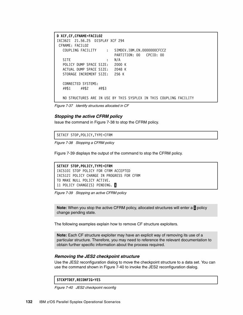
Figure 7-37 Identify structures allocated in CF
Stopping the active CFRM policyIssue the command in Figure 7-38 to stop the CFRM policy.
Figure 7-38 Stopping a CFRM policy
Figure 7-39 displays the output of the command to stop the CFRM policy.
Figure 7-39 Stopping an active CFRM policy
The following examples explain how to remove CF structure exploiters.
Removing the JES2 checkpoint structureUse the JES2 reconfiguration dialog to move the checkpoint structure to a data set. You can use the command shown in Figure 7-40 to invoke the JES2 reconfiguration dialog.
Figure 7-40 JES2 checkpoint reconfig
D XCF,CF,CFNAME=FACIL02 IXC362I 21.56.25 DISPLAY XCF 294 CFNAME: FACIL02 COUPLING FACILITY : SIMDEV.IBM.EN.0000000CFCC2 PARTITION: 00 CPCID: 00 SITE : N/A POLICY DUMP SPACE SIZE: 2000 K ACTUAL DUMP SPACE SIZE: 2048 K STORAGE INCREMENT SIZE: 256 K CONNECTED SYSTEMS: #@$1 #@$2 #@$3 NO STRUCTURES ARE IN USE BY THIS SYSPLEX IN THIS COUPLING FACILITY
SETXCF STOP,POLICY,TYPE=CFRM
SETXCF STOP,POLICY,TYPE=CFRMIXC510I STOP POLICY FOR CFRM ACCEPTEDIXC512I POLICY CHANGE IN PROGRESS FOR CFRMTO MAKE NULL POLICY ACTIVE.11 POLICY CHANGE(S) PENDING. 1
Note: When you stop the active CFRM policy, allocated structures will enter a 1 policy change pending state.
Note: Each CF structure exploiter may have an explicit way of removing its use of a particular structure. Therefore, you may need to reference the relevant documentation to obtain further specific information about the process required.
$TCKPTDEF,RECONFIG=YES
132 IBM z/OS Parallel Sysplex Operational Scenarios

Use the SETXCF FORCE command to delete the persistent JES2 structure after the reconfiguration is completed successfully.
Removing the system logger structures� If any subsystem is using the system logger, provide a normal shutdown of the
subsystem.
� Issue the vary command shown in Figure 7-41 to activate SYSLOG and deactivate OPERLOG.
Figure 7-41 Removing use of OPERLOG for syslog
See Chapter 14, “Managing consoles in a Parallel Sysplex” on page 283 for more information on managing OPERLOG.
� Issue the command shown in Figure 7-42 to stop log stream recording of LOGREC and revert to the disk based data set, if a disk version exists.
Figure 7-42 LOGREC medium reverted back to disk data set
If a disk-based data set is not available, you can request that recording logrec error and environmental records be disabled by issuing the command shown in Figure 7-43.
Figure 7-43 Disable LOGREC recording
Removing the XCF signalling structuresWe are assuming that there are CTC connections available to XCF.
Issue the commands shown in Figure 7-44 to stop the XCF signalling through the structures on all the images in the sysplex.
Figure 7-44 Stopping XCF Pathin/Pathout structures
Disable RACF data sharingIssue the command shown in Figure 7-45 from either TSO or the console to disable RACF data sharing. If entering the command in TSO, you will issue it as shown here.
Figure 7-45 Disabling RACF data sharing in TSO
V SYSLOG,HARDCPYV OPERLOG,HARDCPY,OFF
SETLOGRC DATASET
SETLOGRC IGNORE
RO *ALL,SETXCF STOP,PATHIN,STRNAME=strnameRO *ALL,SETXCF STOP,PATHOUT,STRNAME=strname
RVARY NODATASHARE
Chapter 7. Coupling Facility considerations in a Parallel Sysplex 133
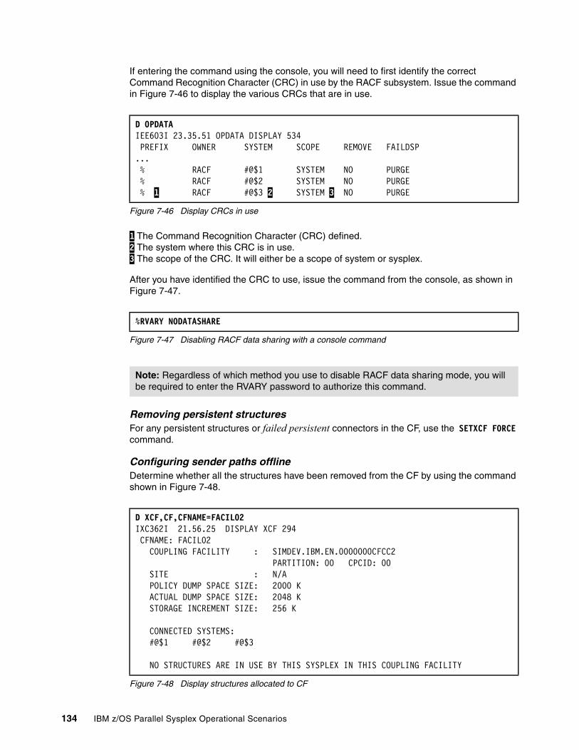
If entering the command using the console, you will need to first identify the correct Command Recognition Character (CRC) in use by the RACF subsystem. Issue the command in Figure 7-46 to display the various CRCs that are in use.
Figure 7-46 Display CRCs in use
1 The Command Recognition Character (CRC) defined. 2 The system where this CRC is in use. 3 The scope of the CRC. It will either be a scope of system or sysplex.
After you have identified the CRC to use, issue the command from the console, as shown in Figure 7-47.
Figure 7-47 Disabling RACF data sharing with a console command
Removing persistent structuresFor any persistent structures or failed persistent connectors in the CF, use the SETXCF FORCE command.
Configuring sender paths offlineDetermine whether all the structures have been removed from the CF by using the command shown in Figure 7-48.
Figure 7-48 Display structures allocated to CF
D OPDATA IEE603I 23.35.51 OPDATA DISPLAY 534 PREFIX OWNER SYSTEM SCOPE REMOVE FAILDSP ...% RACF #@$1 SYSTEM NO PURGE % RACF #@$2 SYSTEM NO PURGE % 1 RACF #@$3 2 SYSTEM 3 NO PURGE
%RVARY NODATASHARE
Note: Regardless of which method you use to disable RACF data sharing mode, you will be required to enter the RVARY password to authorize this command.
D XCF,CF,CFNAME=FACIL02 IXC362I 21.56.25 DISPLAY XCF 294 CFNAME: FACIL02 COUPLING FACILITY : SIMDEV.IBM.EN.0000000CFCC2 PARTITION: 00 CPCID: 00 SITE : N/A POLICY DUMP SPACE SIZE: 2000 K ACTUAL DUMP SPACE SIZE: 2048 K STORAGE INCREMENT SIZE: 256 K CONNECTED SYSTEMS: #@$1 #@$2 #@$3 NO STRUCTURES ARE IN USE BY THIS SYSPLEX IN THIS COUPLING FACILITY
134 IBM z/OS Parallel Sysplex Operational Scenarios
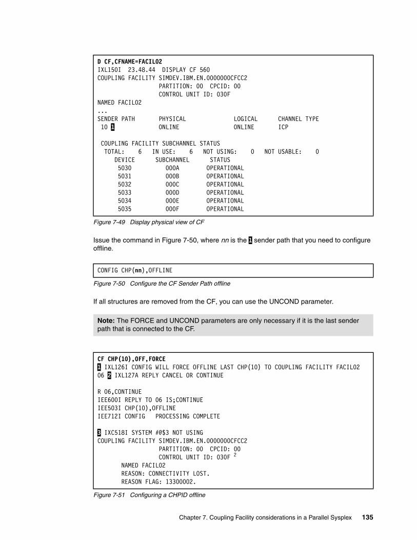
Figure 7-49 Display physical view of CF
Issue the command in Figure 7-50, where nn is the 1 sender path that you need to configure offline.
Figure 7-50 Configure the CF Sender Path offline
If all structures are removed from the CF, you can use the UNCOND parameter.
Figure 7-51 Configuring a CHPID offline
D CF,CFNAME=FACIL02 IXL150I 23.48.44 DISPLAY CF 560 COUPLING FACILITY SIMDEV.IBM.EN.0000000CFCC2 PARTITION: 00 CPCID: 00 CONTROL UNIT ID: 030F NAMED FACIL02 ...SENDER PATH PHYSICAL LOGICAL CHANNEL TYPE 10 1 ONLINE ONLINE ICP
COUPLING FACILITY SUBCHANNEL STATUS TOTAL: 6 IN USE: 6 NOT USING: 0 NOT USABLE: 0 DEVICE SUBCHANNEL STATUS 5030 000A OPERATIONAL 5031 000B OPERATIONAL 5032 000C OPERATIONAL 5033 000D OPERATIONAL 5034 000E OPERATIONAL 5035 000F OPERATIONAL
CONFIG CHP(nn),OFFLINE
Note: The FORCE and UNCOND parameters are only necessary if it is the last sender path that is connected to the CF.
CF CHP(10),OFF,FORCE1 IXL126I CONFIG WILL FORCE OFFLINE LAST CHP(10) TO COUPLING FACILITY FACIL0206 2 IXL127A REPLY CANCEL OR CONTINUE
R 06,CONTINUEIEE600I REPLY TO 06 IS;CONTINUEIEE503I CHP(10),OFFLINEIEE712I CONFIG PROCESSING COMPLETE
3 IXC518I SYSTEM #@$3 NOT USINGCOUPLING FACILITY SIMDEV.IBM.EN.0000000CFCC2 PARTITION: 00 CPCID: 00 CONTROL UNIT ID: 030F 2
NAMED FACIL02 REASON: CONNECTIVITY LOST. REASON FLAG: 13300002.
Chapter 7. Coupling Facility considerations in a Parallel Sysplex 135
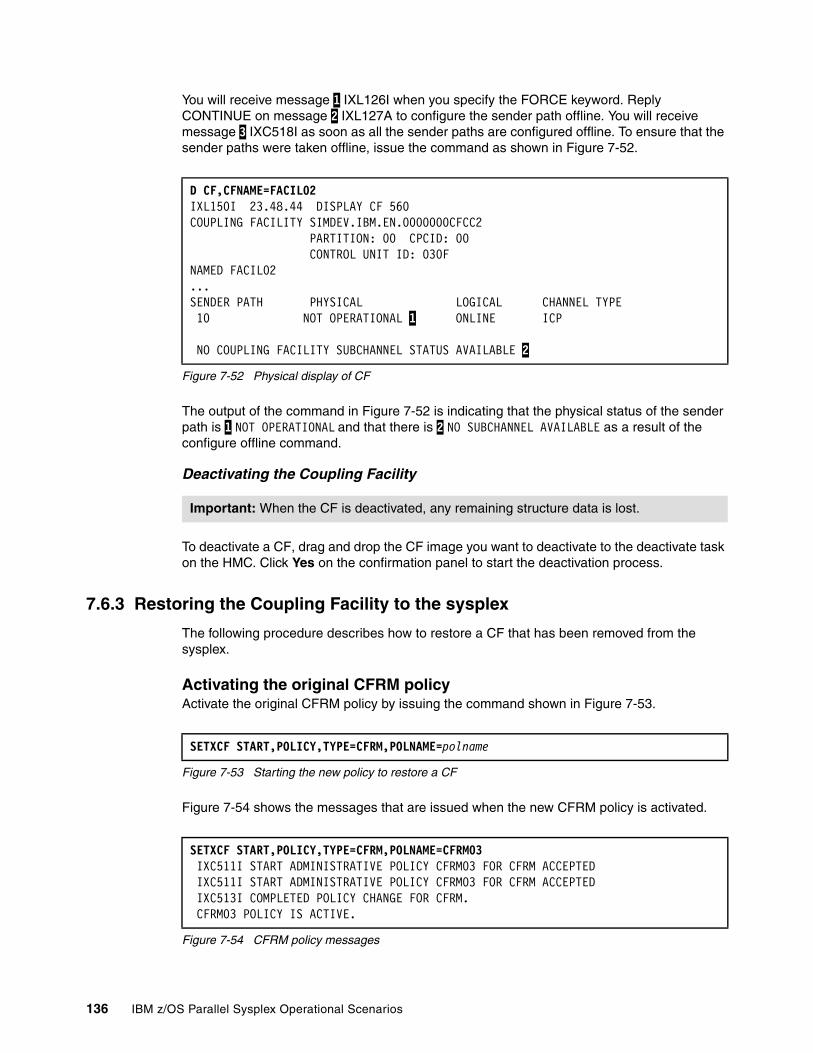
You will receive message 1 IXL126I when you specify the FORCE keyword. Reply CONTINUE on message 2 IXL127A to configure the sender path offline. You will receive message 3 IXC518I as soon as all the sender paths are configured offline. To ensure that the sender paths were taken offline, issue the command as shown in Figure 7-52.
Figure 7-52 Physical display of CF
The output of the command in Figure 7-52 is indicating that the physical status of the sender path is 1 NOT OPERATIONAL and that there is 2 NO SUBCHANNEL AVAILABLE as a result of the configure offline command.
Deactivating the Coupling Facility
To deactivate a CF, drag and drop the CF image you want to deactivate to the deactivate task on the HMC. Click Yes on the confirmation panel to start the deactivation process.
7.6.3 Restoring the Coupling Facility to the sysplex
The following procedure describes how to restore a CF that has been removed from the sysplex.
Activating the original CFRM policyActivate the original CFRM policy by issuing the command shown in Figure 7-53.
Figure 7-53 Starting the new policy to restore a CF
Figure 7-54 shows the messages that are issued when the new CFRM policy is activated.
Figure 7-54 CFRM policy messages
D CF,CFNAME=FACIL02 IXL150I 23.48.44 DISPLAY CF 560 COUPLING FACILITY SIMDEV.IBM.EN.0000000CFCC2 PARTITION: 00 CPCID: 00 CONTROL UNIT ID: 030F NAMED FACIL02 ...SENDER PATH PHYSICAL LOGICAL CHANNEL TYPE 10 NOT OPERATIONAL 1 ONLINE ICP NO COUPLING FACILITY SUBCHANNEL STATUS AVAILABLE 2
Important: When the CF is deactivated, any remaining structure data is lost.
SETXCF START,POLICY,TYPE=CFRM,POLNAME=polname
SETXCF START,POLICY,TYPE=CFRM,POLNAME=CFRM03 IXC511I START ADMINISTRATIVE POLICY CFRM03 FOR CFRM ACCEPTED IXC511I START ADMINISTRATIVE POLICY CFRM03 FOR CFRM ACCEPTED IXC513I COMPLETED POLICY CHANGE FOR CFRM. CFRM03 POLICY IS ACTIVE.
136 IBM z/OS Parallel Sysplex Operational Scenarios

Activating the Coupling FacilityIf the CF is not already added to the sysplex, follow the procedure described in 7.6.1, “Adding a Coupling Facility” on page 120.
Moving the structuresAfter the CF has become active, you should then ensure that the various structures are located in the correct CF as defined in the current active CFRM policy. This can be achieved by using either the POPULATECF or REALLOCATE parameters of the SETXCF START command to relocate the Coupling Facility structures.
For a detailed discussion about REALLOCATE and REBUILD with POPULATECF, refer to “REALLOCATE or REBUILD POPULATECF command” on page 154.
You can also manually rebuild the structures that have been rebuilt to an alternate CF. Issue the command shown in Figure 7-55 to rebuild the structures to the original CF.
Figure 7-55 SETXCF START Rebuild command
The LOC=OTHER parameter may be needed, depending on the CFRM policy structure preference list.
For more information about the rebuild command, refer to 7.8.1, “Rebuilding structures that support rebuild” on page 147.
For more information and a list of structures that do not support rebuild, refer to Appendix B, “List of structures” on page 499.
Restart any other subsystems that have been stopped during the CF shutdown procedure.
7.7 Coupling Facility Control Code (CFCC) commands
The CFCC supports a limited number of operator commands. These commands can only be issued using the HMC (Operating System Messages) interface. For more information about these commands, refer to HMC online documentation.
To invoke the operating messages panel on the HMC, drag and drop the CF image object on the operating system messages task.
7.7.1 CFCC display commands
Important: The use of the REALLOCATE process and the POPULATECF command are mutually exclusive.
SETXCF START,REBUILD,STRNAME=strname
Note: After the CF and CFRM policy are restored, some functions might reconnect to the CF automatically, depending on the method used to remove the structures.
Note: The HMC used to issue the CFCC Display commands is at HMC Driver Level 64 and Coupling Facility Control Code (CFCC) level 15.
Chapter 7. Coupling Facility considerations in a Parallel Sysplex 137
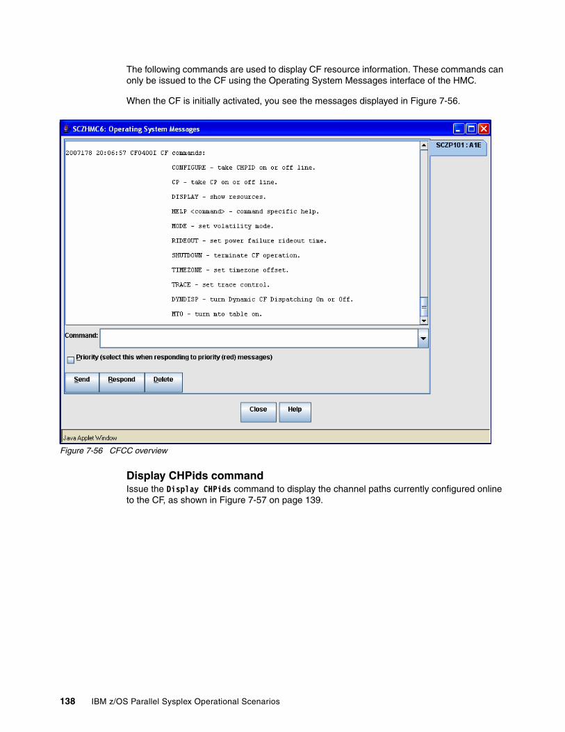
The following commands are used to display CF resource information. These commands can only be issued to the CF using the Operating System Messages interface of the HMC.
When the CF is initially activated, you see the messages displayed in Figure 7-56.
Figure 7-56 CFCC overview
Display CHPids commandIssue the Display CHPids command to display the channel paths currently configured online to the CF, as shown in Figure 7-57 on page 139.
138 IBM z/OS Parallel Sysplex Operational Scenarios
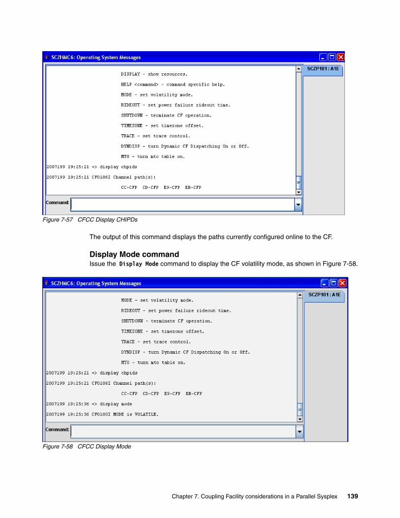
Figure 7-57 CFCC Display CHIPDs
The output of this command displays the paths currently configured online to the CF.
Display Mode commandIssue the Display Mode command to display the CF volatility mode, as shown in Figure 7-58.
Figure 7-58 CFCC Display Mode
Chapter 7. Coupling Facility considerations in a Parallel Sysplex 139
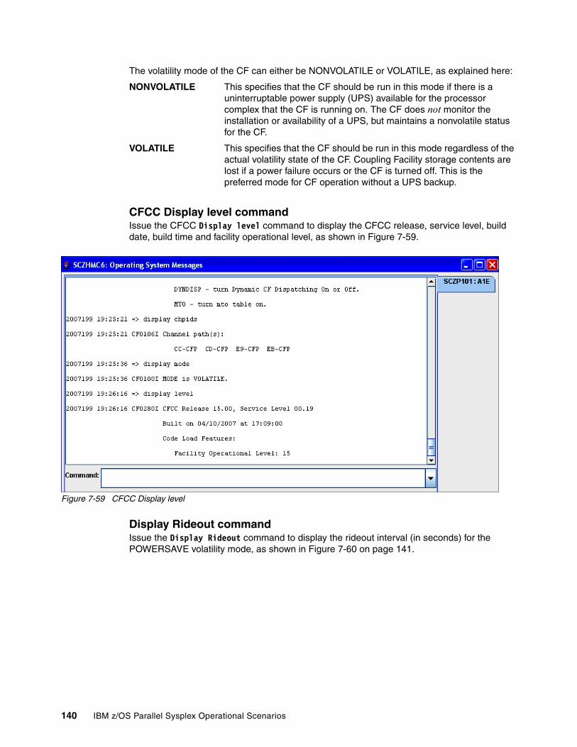
The volatility mode of the CF can either be NONVOLATILE or VOLATILE, as explained here:
NONVOLATILE This specifies that the CF should be run in this mode if there is a uninterruptable power supply (UPS) available for the processor complex that the CF is running on. The CF does not monitor the installation or availability of a UPS, but maintains a nonvolatile status for the CF.
VOLATILE This specifies that the CF should be run in this mode regardless of the actual volatility state of the CF. Coupling Facility storage contents are lost if a power failure occurs or the CF is turned off. This is the preferred mode for CF operation without a UPS backup.
CFCC Display level commandIssue the CFCC Display level command to display the CFCC release, service level, build date, build time and facility operational level, as shown in Figure 7-59.
Figure 7-59 CFCC Display level
Display Rideout commandIssue the Display Rideout command to display the rideout interval (in seconds) for the POWERSAVE volatility mode, as shown in Figure 7-60 on page 141.
140 IBM z/OS Parallel Sysplex Operational Scenarios

Figure 7-60 CFCC Display Rideout
Display Resources commandIssue the Display Resources command to display the number of processors, receiver paths (CFRs) and storage available to the CF, as shown in Figure 7-61.
Figure 7-61 CFCC Display Resources
Display Timezone commandIssue the Display Timezone command to display the hours east or west of Greenwich Mean Time (GMT) used to adjust time stamps in messages, as shown in Figure 7-62 on page 142.
Chapter 7. Coupling Facility considerations in a Parallel Sysplex 141
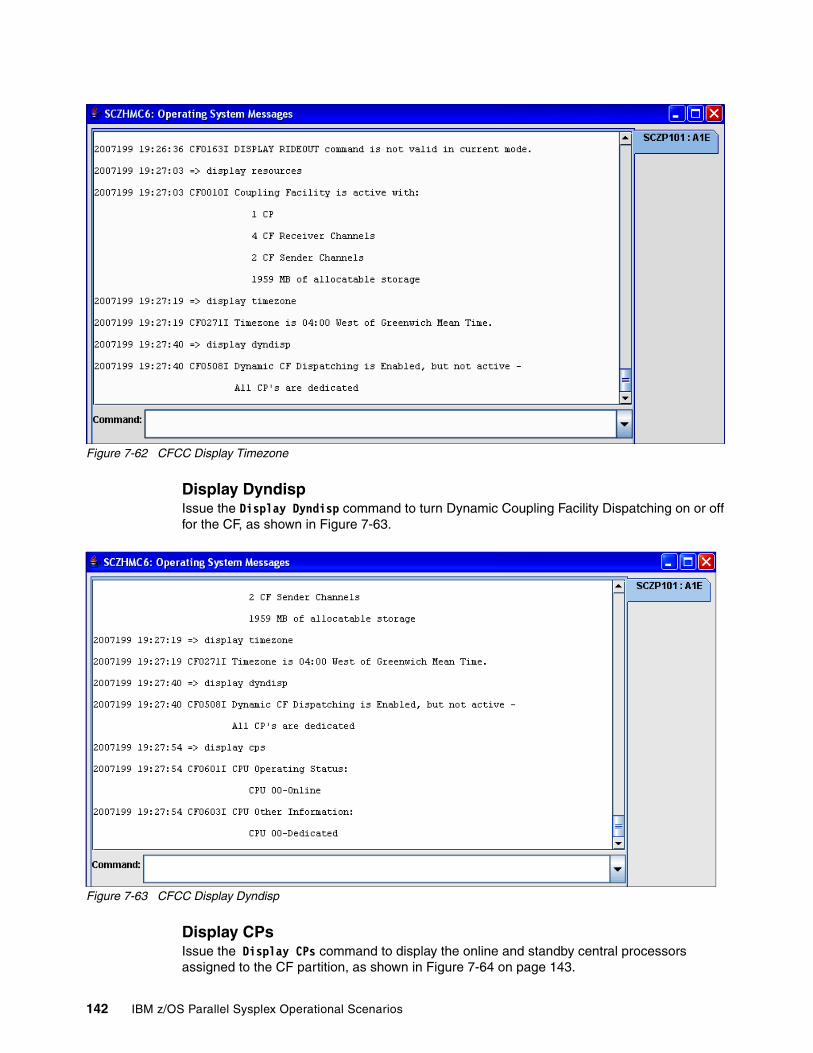
Figure 7-62 CFCC Display Timezone
Display DyndispIssue the Display Dyndisp command to turn Dynamic Coupling Facility Dispatching on or off for the CF, as shown in Figure 7-63.
Figure 7-63 CFCC Display Dyndisp
Display CPsIssue the Display CPs command to display the online and standby central processors assigned to the CF partition, as shown in Figure 7-64 on page 143.
142 IBM z/OS Parallel Sysplex Operational Scenarios
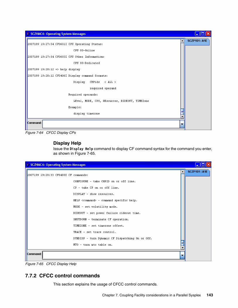
Figure 7-64 CFCC Display CPs
Display HelpIssue the Display Help command to display CF command syntax for the command you enter, as shown in Figure 7-65.
Figure 7-65 CFCC Display Help
7.7.2 CFCC control commands
This section explains the usage of CFCC control commands.
Chapter 7. Coupling Facility considerations in a Parallel Sysplex 143

Dynamic CF dispatchingYou can enable dynamic CF dispatching for a CF image in order to use it as a backup CF if the primary CF fails. Issue the command shown in Figure 7-66 to enable or disable dynamic CF dispatching.
Figure 7-66 Enabling/disabling dynamic CF dispatching
The message shown in Figure 7-67 will be displayed if you attempt to enable dynamic CF dispatching on dedicated CF processors.
Figure 7-67 Message when enabling dynamic CF dispatching on dedicated CF processors
With dynamic CF dispatching enabled, you see the following:
� It uses minimal processor resources despite its assigned processing weight.
� Its unused processor resources are shared with other active logical partitions until it is needed as a backup CF.
� It automatically becomes a backup CF if the primary CF fails.
� It uses its full share of processor weight only while it is in use as a backup CF.
Change mode of CF operationThis defines the volatility mode to be used for CF operation.
POWERSAVEThis specifies that the CF runs in POWERSAVE mode and that CF storage contents are nonvolatile if the battery backup feature is installed and its battery is online and charged. Issue the command shown in Figure 7-68 to enable POWERSAVE.
Figure 7-68 Enabling POWERSAVE mode
If the volatility state of the CF remains nonvolatile, running in POWERSAVE mode assures the following:
� If a utility power failure occurs and utility power does not return before a rideout interval completes, the CF will cease operation and save its storage contents across the utility power failure. When power is restored in the CF, CF storage contents will be intact and do not have to be rebuilt.
� If a utility power failure occurs and utility power returns before a rideout interval completes, CF operation continues. You specify the length of the rideout interval using the RIDEOUT command. POWERSAVE is the default volatility mode.
DYNDISP ON|OFF
DYNDISP ONCF0505I DYNDISP command cancelled Command has no effect with dedicated CP's
MODE POWERSAVECF0102I MODE is POWER SAVE. Current status is NONVOLATILE. Power-Save resources are available.
144 IBM z/OS Parallel Sysplex Operational Scenarios

VOLATILEThis specifies that the CF runs in volatile mode regardless of the actual volatility state of the CF. CF storage contents are lost if a power failure occurs or if CF power is turned off. This is the preferred mode for CF operation without an UPS backup or internal battery feature (IBF). Issue the command shown in Figure 7-69 to change the CF to volatile mode.
Figure 7-69 Changing mode to VOLATILE
NONVOLATILEThis specifies that the CF runs in nonvolatile mode. This should be used if a UPS is available for the processor complex that the CF is running on. The CF does not monitor the installation or availability of a UPS, but maintains a nonvolatile status for the CF. Issue the command shown in Figure 7-70 to change the CF to nonvolatile mode.
Figure 7-70 Changing mode to NONVOLATILE
Change the rideout time intervalThis defines the rideout interval for a CF operating in POWERSAVE mode. The rideout interval is the consecutive amount of time that utility power must be off before the CF begins to shut down. When the rideout interval completes, the CF shuts down and battery power is diverted to preserve CF storage contents in CF storage until power is restored. The default interval is 10 seconds. Issue the command shown in Figure 7-71 to change the rideout interval.
Figure 7-71 Changing the rideout time interval
Shutdown CFCCThis ends CF operation and puts all CF logical central processors (CPs) into a disabled wait state. Issue the command shown in Figure 7-72 to shut down the CF.
Figure 7-72 Shutdown command
Enter YES to confirm the shutdown.
MODE VOLATILECF0100I MODE is VOLATILE
MODE NONVOLATILECF0100I MODE is NONVOLATILE
RIDEOUT 20CF0162I Rideout is set to 20 seconds.
SHUTDOWNCF0082A If SHUTDOWN is confirmed, shared data will be lost; CF0090A Do you really want to shut down the Coupling Facility? (YES/NO)
YES
Attention: By responding YES to the prompt in Figure 7-72, any shared data that remains in the CF will be lost.
Chapter 7. Coupling Facility considerations in a Parallel Sysplex 145

7.7.3 CFCC Help commands
The following help commands are available.
General HelpIssue the command shown in Figure 7-73 to obtain a list of available CFCC commands.
Figure 7-73 General CFCC Help command
Specific HelpIssue the command shown in Figure 7-74 to obtain help regarding a specific CFCC command.
Figure 7-74 Specific HELP for a CFCC command
As an example, the output shown in Figure 7-75 displays help information about the CONFIGURE command.
Figure 7-75 Requesting specific HELP for the CONFIGURE command
HELP command
HELP CONFIGURECF0403I Configure command formats: CONfigure † xx † ONline † xx † OFFline Where xx is a hex CHPID number. Example: configure 11 offline
146 IBM z/OS Parallel Sysplex Operational Scenarios
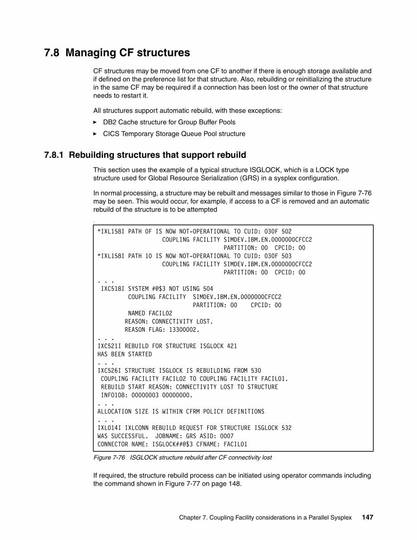
7.8 Managing CF structures
CF structures may be moved from one CF to another if there is enough storage available and if defined on the preference list for that structure. Also, rebuilding or reinitializing the structure in the same CF may be required if a connection has been lost or the owner of that structure needs to restart it.
All structures support automatic rebuild, with these exceptions:
� DB2 Cache structure for Group Buffer Pools
� CICS Temporary Storage Queue Pool structure
7.8.1 Rebuilding structures that support rebuild
This section uses the example of a typical structure ISGLOCK, which is a LOCK type structure used for Global Resource Serialization (GRS) in a sysplex configuration.
In normal processing, a structure may be rebuilt and messages similar to those in Figure 7-76 may be seen. This would occur, for example, if access to a CF is removed and an automatic rebuild of the structure is to be attempted
.
Figure 7-76 ISGLOCK structure rebuild after CF connectivity lost
If required, the structure rebuild process can be initiated using operator commands including the command shown in Figure 7-77 on page 148.
*IXL158I PATH 0F IS NOW NOT-OPERATIONAL TO CUID: 030F 502 COUPLING FACILITY SIMDEV.IBM.EN.0000000CFCC2 PARTITION: 00 CPCID: 00 *IXL158I PATH 10 IS NOW NOT-OPERATIONAL TO CUID: 030F 503 COUPLING FACILITY SIMDEV.IBM.EN.0000000CFCC2 PARTITION: 00 CPCID: 00 . . . IXC518I SYSTEM #@$3 NOT USING 504 COUPLING FACILITY SIMDEV.IBM.EN.0000000CFCC2 PARTITION: 00 CPCID: 00 NAMED FACIL02 REASON: CONNECTIVITY LOST. REASON FLAG: 13300002. . . .IXC521I REBUILD FOR STRUCTURE ISGLOCK 421 HAS BEEN STARTED . . .IXC526I STRUCTURE ISGLOCK IS REBUILDING FROM 530 COUPLING FACILITY FACIL02 TO COUPLING FACILITY FACIL01. REBUILD START REASON: CONNECTIVITY LOST TO STRUCTURE INFO108: 00000003 00000000.. . .ALLOCATION SIZE IS WITHIN CFRM POLICY DEFINITIONS . . .IXL014I IXLCONN REBUILD REQUEST FOR STRUCTURE ISGLOCK 532 WAS SUCCESSFUL. JOBNAME: GRS ASID: 0007 CONNECTOR NAME: ISGLOCK##@$3 CFNAME: FACIL01
Chapter 7. Coupling Facility considerations in a Parallel Sysplex 147

Figure 7-77 SETXCF START REBUILD command for a structure
There are several reasons why a structure may have to be rebuilt, including performance, structure size changes, or maintenance.
Rebuilding Coupling Facility structures in either Coupling FacilityIssue the D XCF,STR,STRNM=strname command to check the status of the structure and which CF it is attached to; see Figure 7-78.
Figure 7-78 Displaying a structure allocated and its connections
SETXCF START,REBUILD,STRNAME=strname.
D XCF,STR,STRNM=ISGLOCK IXC360I 01.27.02 DISPLAY XCF 742 STRNAME: ISGLOCK STATUS: ALLOCATED TYPE: LOCK POLICY INFORMATION: POLICY SIZE : 8704 K POLICY INITSIZE: 8704 K POLICY MINSIZE : 0 K FULLTHRESHOLD : 80 ALLOWAUTOALT : NO REBUILD PERCENT: 1 DUPLEX : DISABLED ALLOWREALLOCATE: YES PREFERENCE LIST: FACIL02 FACIL01 ENFORCEORDER : NO EXCLUSION LIST IS EMPTY ACTIVE STRUCTURE ---------------- ALLOCATION TIME: 06/28/2007 00:53:21 CFNAME : FACIL02 COUPLING FACILITY: SIMDEV.IBM.EN.0000000CFCC2 PARTITION: 00 CPCID: 00 ACTUAL SIZE : 8448 K STORAGE INCREMENT SIZE: 256 K LOCKS: TOTAL: 1048576 PHYSICAL VERSION: C0D006D0 BD410282 LOGICAL VERSION: C0D006D0 BD410282 SYSTEM-MANAGED PROCESS LEVEL: 8 XCF GRPNAME : IXCLO007 DISPOSITION : DELETE ACCESS TIME : 0 MAX CONNECTIONS: 32 # CONNECTIONS : 3 CONNECTION NAME ID VERSION SYSNAME JOBNAME ASID STATE ---------------- -- -------- -------- -------- ---- -------- ISGLOCK##@$1 03 00030069 #@$1 GRS 0007 ACTIVE ISGLOCK##@$2 01 00010090 #@$2 GRS 0007 ACTIVE ISGLOCK##@$3 02 00020063 #@$3 GRS 0007 ACTIVE
148 IBM z/OS Parallel Sysplex Operational Scenarios
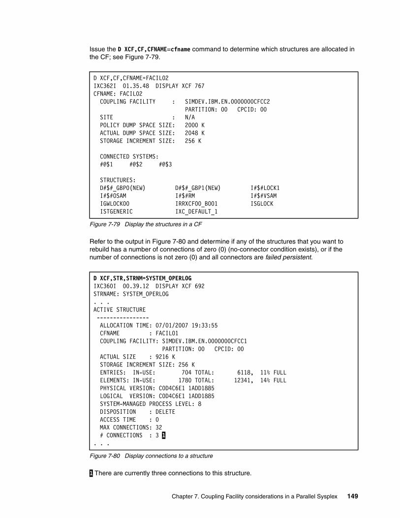
Issue the D XCF,CF,CFNAME=cfname command to determine which structures are allocated in the CF; see Figure 7-79.
Figure 7-79 Display the structures in a CF
Refer to the output in Figure 7-80 and determine if any of the structures that you want to rebuild has a number of connections of zero (0) (no-connector condition exists), or if the number of connections is not zero (0) and all connectors are failed persistent.
Figure 7-80 Display connections to a structure
1 There are currently three connections to this structure.
D XCF,CF,CFNAME=FACIL02 IXC362I 01.35.48 DISPLAY XCF 767 CFNAME: FACIL02 COUPLING FACILITY : SIMDEV.IBM.EN.0000000CFCC2 PARTITION: 00 CPCID: 00 SITE : N/A POLICY DUMP SPACE SIZE: 2000 K ACTUAL DUMP SPACE SIZE: 2048 K STORAGE INCREMENT SIZE: 256 K CONNECTED SYSTEMS: #@$1 #@$2 #@$3 STRUCTURES: D#$#_GBP0(NEW) D#$#_GBP1(NEW) I#$#LOCK1 I#$#OSAM I#$#RM I#$#VSAM IGWLOCK00 IRRXCF00_B001 ISGLOCK
ISTGENERIC IXC_DEFAULT_1
D XCF,STR,STRNM=SYSTEM_OPERLOG IXC360I 00.39.12 DISPLAY XCF 692 STRNAME: SYSTEM_OPERLOG . . .ACTIVE STRUCTURE ---------------- ALLOCATION TIME: 07/01/2007 19:33:55 CFNAME : FACIL01 COUPLING FACILITY: SIMDEV.IBM.EN.0000000CFCC1 PARTITION: 00 CPCID: 00 ACTUAL SIZE : 9216 K STORAGE INCREMENT SIZE: 256 K ENTRIES: IN-USE: 704 TOTAL: 6118, 11% FULL ELEMENTS: IN-USE: 1780 TOTAL: 12341, 14% FULL PHYSICAL VERSION: C0D4C6E1 1ADD1885 LOGICAL VERSION: C0D4C6E1 1ADD1885 SYSTEM-MANAGED PROCESS LEVEL: 8 DISPOSITION : DELETE ACCESS TIME : 0 MAX CONNECTIONS: 32 # CONNECTIONS : 3 1. . .
Chapter 7. Coupling Facility considerations in a Parallel Sysplex 149
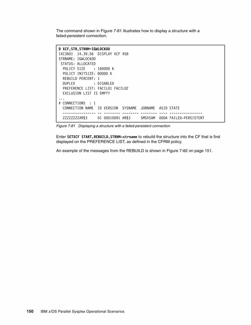
The command shown in Figure 7-81 illustrates how to display a structure with a failed-persistent connection.
Figure 7-81 Displaying a structure with a failed-persistent connection
Enter SETXCF START,REBUILD,STRNM=strname to rebuild the structure into the CF that is first displayed on the PREFERENCE LIST, as defined in the CFRM policy.
An example of the messages from the REBUILD is shown in Figure 7-82 on page 151.
D XCF,STR,STRNM=IGWLOCK00IXC360I 14.39.56 DISPLAY XCF 458STRNAME: IGWLOCK00 STATUS: ALLOCATED POLICY SIZE : 160000 K POLICY INITSIZE: 80000 K REBUILD PERCENT: 1 DUPLEX : DISABLED PREFERENCE LIST: FACIL01 FACIL02 EXCLUSION LIST IS EMPTY...# CONNECTIONS : 1 CONNECTION NAME ID VERSION SYSNAME JOBNAME ASID STATE ---------------- -- -------- -------- -------- ---- ----------------
ZZZZZZZZ#@$3 01 00010091 #@$3 SMSVSAM 000A FAILED-PERSISTENT
150 IBM z/OS Parallel Sysplex Operational Scenarios
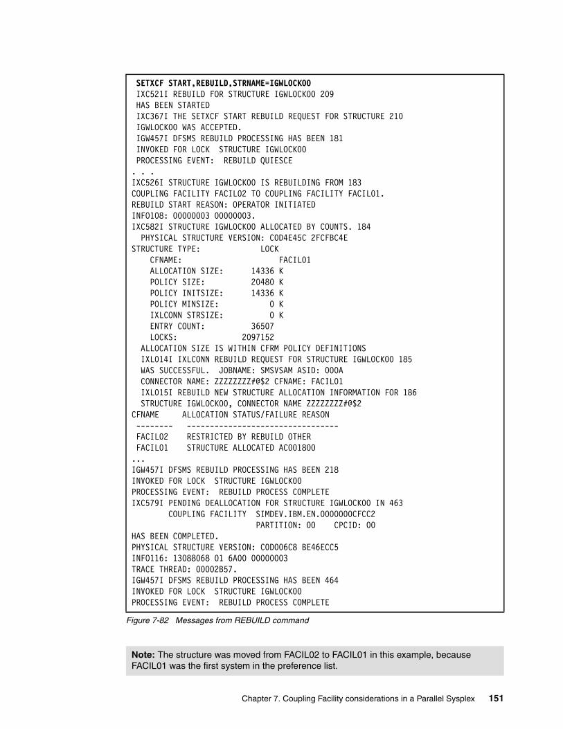
Figure 7-82 Messages from REBUILD command
SETXCF START,REBUILD,STRNAME=IGWLOCK00 IXC521I REBUILD FOR STRUCTURE IGWLOCK00 209 HAS BEEN STARTED IXC367I THE SETXCF START REBUILD REQUEST FOR STRUCTURE 210 IGWLOCK00 WAS ACCEPTED. IGW457I DFSMS REBUILD PROCESSING HAS BEEN 181 INVOKED FOR LOCK STRUCTURE IGWLOCK00 PROCESSING EVENT: REBUILD QUIESCE . . .IXC526I STRUCTURE IGWLOCK00 IS REBUILDING FROM 183 COUPLING FACILITY FACIL02 TO COUPLING FACILITY FACIL01. REBUILD START REASON: OPERATOR INITIATED INFO108: 00000003 00000003. IXC582I STRUCTURE IGWLOCK00 ALLOCATED BY COUNTS. 184 PHYSICAL STRUCTURE VERSION: C0D4E45C 2FCFBC4E STRUCTURE TYPE: LOCK CFNAME: FACIL01 ALLOCATION SIZE: 14336 K POLICY SIZE: 20480 K POLICY INITSIZE: 14336 K POLICY MINSIZE: 0 K IXLCONN STRSIZE: 0 K ENTRY COUNT: 36507 LOCKS: 2097152 ALLOCATION SIZE IS WITHIN CFRM POLICY DEFINITIONS IXL014I IXLCONN REBUILD REQUEST FOR STRUCTURE IGWLOCK00 185 WAS SUCCESSFUL. JOBNAME: SMSVSAM ASID: 000A CONNECTOR NAME: ZZZZZZZZ#@$2 CFNAME: FACIL01 IXL015I REBUILD NEW STRUCTURE ALLOCATION INFORMATION FOR 186 STRUCTURE IGWLOCK00, CONNECTOR NAME ZZZZZZZZ#@$2 CFNAME ALLOCATION STATUS/FAILURE REASON -------- --------------------------------- FACIL02 RESTRICTED BY REBUILD OTHER FACIL01 STRUCTURE ALLOCATED AC001800 ...IGW457I DFSMS REBUILD PROCESSING HAS BEEN 218 INVOKED FOR LOCK STRUCTURE IGWLOCK00 PROCESSING EVENT: REBUILD PROCESS COMPLETE IXC579I PENDING DEALLOCATION FOR STRUCTURE IGWLOCK00 IN 463 COUPLING FACILITY SIMDEV.IBM.EN.0000000CFCC2 PARTITION: 00 CPCID: 00 HAS BEEN COMPLETED. PHYSICAL STRUCTURE VERSION: C0D006C8 BE46ECC5 INFO116: 13088068 01 6A00 00000003 TRACE THREAD: 00002B57. IGW457I DFSMS REBUILD PROCESSING HAS BEEN 464 INVOKED FOR LOCK STRUCTURE IGWLOCK00 PROCESSING EVENT: REBUILD PROCESS COMPLETE
Note: The structure was moved from FACIL02 to FACIL01 in this example, because FACIL01 was the first system in the preference list.
Chapter 7. Coupling Facility considerations in a Parallel Sysplex 151
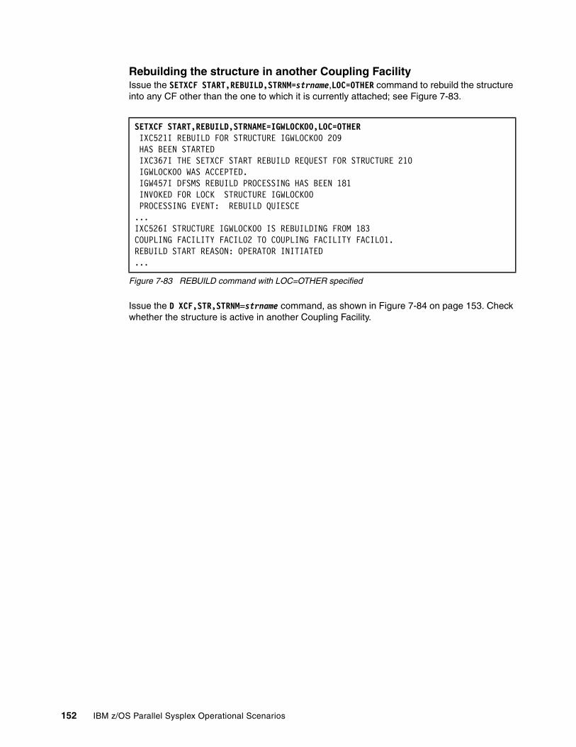
Rebuilding the structure in another Coupling FacilityIssue the SETXCF START,REBUILD,STRNM=strname,LOC=OTHER command to rebuild the structure into any CF other than the one to which it is currently attached; see Figure 7-83.
Figure 7-83 REBUILD command with LOC=OTHER specified
Issue the D XCF,STR,STRNM=strname command, as shown in Figure 7-84 on page 153. Check whether the structure is active in another Coupling Facility.
SETXCF START,REBUILD,STRNAME=IGWLOCK00,LOC=OTHER IXC521I REBUILD FOR STRUCTURE IGWLOCK00 209 HAS BEEN STARTED IXC367I THE SETXCF START REBUILD REQUEST FOR STRUCTURE 210 IGWLOCK00 WAS ACCEPTED. IGW457I DFSMS REBUILD PROCESSING HAS BEEN 181 INVOKED FOR LOCK STRUCTURE IGWLOCK00 PROCESSING EVENT: REBUILD QUIESCE ...IXC526I STRUCTURE IGWLOCK00 IS REBUILDING FROM 183 COUPLING FACILITY FACIL02 TO COUPLING FACILITY FACIL01. REBUILD START REASON: OPERATOR INITIATED...
152 IBM z/OS Parallel Sysplex Operational Scenarios

Figure 7-84 Displaying the location of a structure
The preference list is 1 FACIL02, FACIL01, and the CFNAME is 2 FACIL01.
D XCF,STR,STRNM=IGWLOCK00 IXC360I 02.28.37 DISPLAY XCF 897 STRNAME: IGWLOCK00 STATUS: ALLOCATED EVENT MANAGEMENT: POLICY-BASED TYPE: LOCK POLICY INFORMATION: POLICY SIZE : 20480 K POLICY INITSIZE: 14336 K POLICY MINSIZE : 0 K FULLTHRESHOLD : 80 ALLOWAUTOALT : NO REBUILD PERCENT: N/A DUPLEX : DISABLED ALLOWREALLOCATE: YES PREFERENCE LIST: FACIL02 FACIL01 1 ENFORCEORDER : NO EXCLUSION LIST IS EMPTY ACTIVE STRUCTURE ---------------- ALLOCATION TIME: 07/01/2007 22:02:55 CFNAME : FACIL01 2 COUPLING FACILITY: SIMDEV.IBM.EN.0000000CFCC1 PARTITION: 00 CPCID: 00 ACTUAL SIZE : 14336 K STORAGE INCREMENT SIZE: 256 K ENTRIES: IN-USE: 0 TOTAL: 36507, 0% FULL LOCKS: TOTAL: 2097152 PHYSICAL VERSION: C0D4E82E BDEF7B05 LOGICAL VERSION: C0D4E82E BDEF7B05 SYSTEM-MANAGED PROCESS LEVEL: 8 XCF GRPNAME : IXCLO000 DISPOSITION : KEEP ACCESS TIME : 0 NUMBER OF RECORD DATA LISTS PER CONNECTION: 16 MAX CONNECTIONS: 4 # CONNECTIONS : 3 CONNECTION NAME ID VERSION SYSNAME JOBNAME ASID STATE ---------------- -- -------- -------- -------- ---- ---------- ZZZZZZZZ#@$1 03 00030077 #@$1 SMSVSAM 000A ACTIVE ZZZZZZZZ#@$2 02 0002006C #@$2 SMSVSAM 000A ACTIVE ZZZZZZZZ#@$3 01 00010091 #@$3 SMSVSAM 000A ACTIVE DIAGNOSTIC INFORMATION: STRNUM: 00000000 STRSEQ: 00000000 MANAGER SYSTEM ID: 00000000 EVENT MANAGEMENT: POLICY-BASED
Chapter 7. Coupling Facility considerations in a Parallel Sysplex 153
REALLOCATE or REBUILD POPULATECF commandThere are two supported commands for rebuilding structures from one CF to another.
The POPULATECF function and the REALLOCATE process are mutually exclusive.
The REALLOCATE process provides a simple, broad-based structure placement optimization via an MVS command. It simplifies many CF maintenance procedures.
The most significant advantage of the REALLOCATE process applies to environments that have any of these conditions:
� More than two CFs
� Duplexed structures, such as DB2 Group Buffer Pools
� Installations wanting structures to always reside in specific CFs whenever possible
� Configurations with CFs having different characteristics, such as different CF levels or processor speeds
The REALLOCATE process will:
� Clear all CFRM “policy change pending” conditions.
� Move all simplex structures into their most preferred CF location.
� Move all duplexed structure instances into their two most preferred CF locations, in the correct order. It automatically corrects reversal of the primary and secondary structure locations
� Act on one structure at a time to minimize any disruption caused by reallocation actions.
� Issue a message describing the evaluation process for each allocated structure.
� Issue a summary message upon completion of all structures and summarizing actions taken.
� Simplify CF structure movement during disruptive CF maintenance or upgrades.
When the REALLOCATE process does not select an allocated structure, message IXC544I is issued with an explanation. See Figure 7-85 on page 155 for an example of the message.
Tip: We recommend using the REALLOCATE command. The REALLOCATE command is integrated into z/OS 1.8, and via APAR OA08688 for z/OS 1.4 and above.
Note: The REALLOCATE process will not be started when XCF discovers an active system in the sysplex without the prerequisite z/OS operating system support.
154 IBM z/OS Parallel Sysplex Operational Scenarios
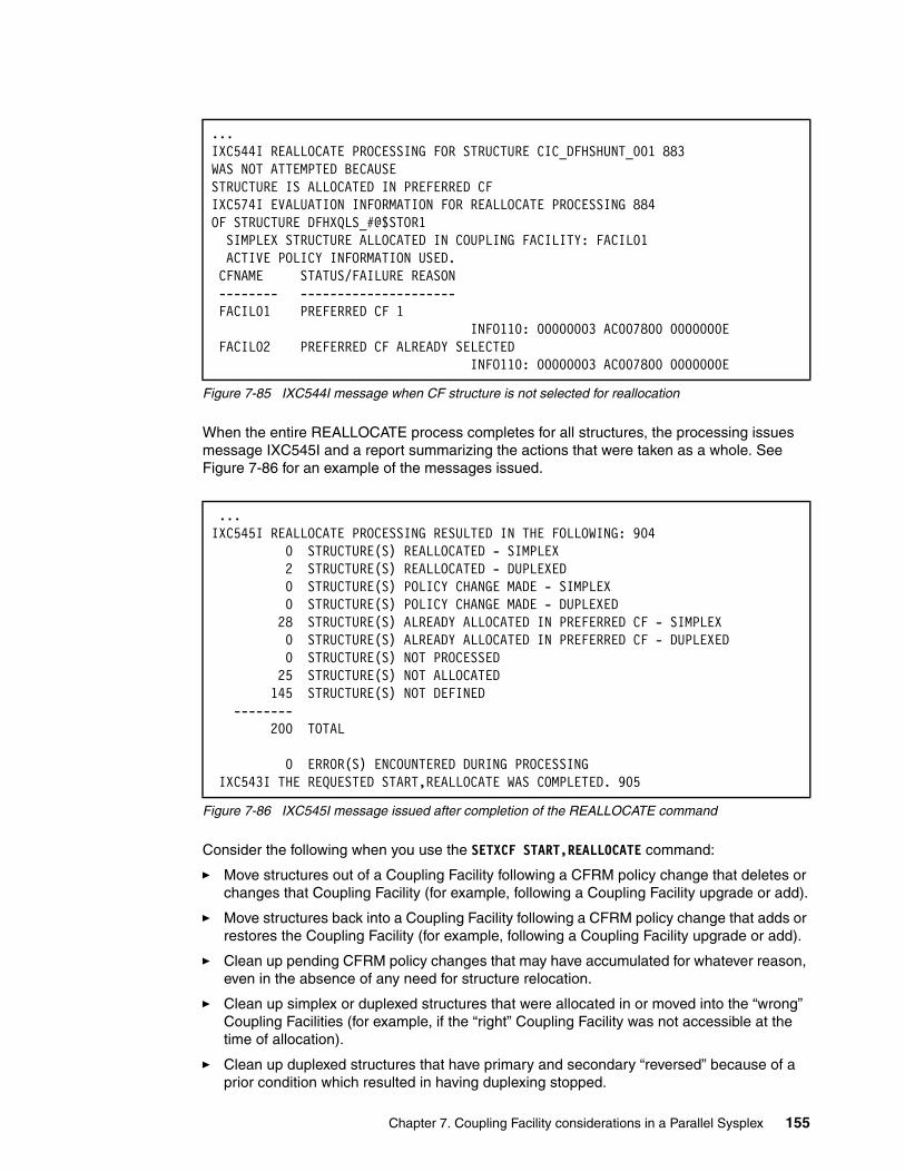
Figure 7-85 IXC544I message when CF structure is not selected for reallocation
When the entire REALLOCATE process completes for all structures, the processing issues message IXC545I and a report summarizing the actions that were taken as a whole. See Figure 7-86 for an example of the messages issued.
Figure 7-86 IXC545I message issued after completion of the REALLOCATE command
Consider the following when you use the SETXCF START,REALLOCATE command:
� Move structures out of a Coupling Facility following a CFRM policy change that deletes or changes that Coupling Facility (for example, following a Coupling Facility upgrade or add).
� Move structures back into a Coupling Facility following a CFRM policy change that adds or restores the Coupling Facility (for example, following a Coupling Facility upgrade or add).
� Clean up pending CFRM policy changes that may have accumulated for whatever reason, even in the absence of any need for structure relocation.
� Clean up simplex or duplexed structures that were allocated in or moved into the “wrong” Coupling Facilities (for example, if the “right” Coupling Facility was not accessible at the time of allocation).
� Clean up duplexed structures that have primary and secondary “reversed” because of a prior condition which resulted in having duplexing stopped.
...IXC544I REALLOCATE PROCESSING FOR STRUCTURE CIC_DFHSHUNT_001 883 WAS NOT ATTEMPTED BECAUSE STRUCTURE IS ALLOCATED IN PREFERRED CF IXC574I EVALUATION INFORMATION FOR REALLOCATE PROCESSING 884 OF STRUCTURE DFHXQLS_#@$STOR1 SIMPLEX STRUCTURE ALLOCATED IN COUPLING FACILITY: FACIL01 ACTIVE POLICY INFORMATION USED. CFNAME STATUS/FAILURE REASON -------- --------------------- FACIL01 PREFERRED CF 1 INFO110: 00000003 AC007800 0000000E FACIL02 PREFERRED CF ALREADY SELECTED INFO110: 00000003 AC007800 0000000E
...IXC545I REALLOCATE PROCESSING RESULTED IN THE FOLLOWING: 904 0 STRUCTURE(S) REALLOCATED - SIMPLEX 2 STRUCTURE(S) REALLOCATED - DUPLEXED 0 STRUCTURE(S) POLICY CHANGE MADE - SIMPLEX 0 STRUCTURE(S) POLICY CHANGE MADE - DUPLEXED 28 STRUCTURE(S) ALREADY ALLOCATED IN PREFERRED CF - SIMPLEX 0 STRUCTURE(S) ALREADY ALLOCATED IN PREFERRED CF - DUPLEXED 0 STRUCTURE(S) NOT PROCESSED 25 STRUCTURE(S) NOT ALLOCATED 145 STRUCTURE(S) NOT DEFINED -------- 200 TOTAL 0 ERROR(S) ENCOUNTERED DURING PROCESSING IXC543I THE REQUESTED START,REALLOCATE WAS COMPLETED. 905
Chapter 7. Coupling Facility considerations in a Parallel Sysplex 155
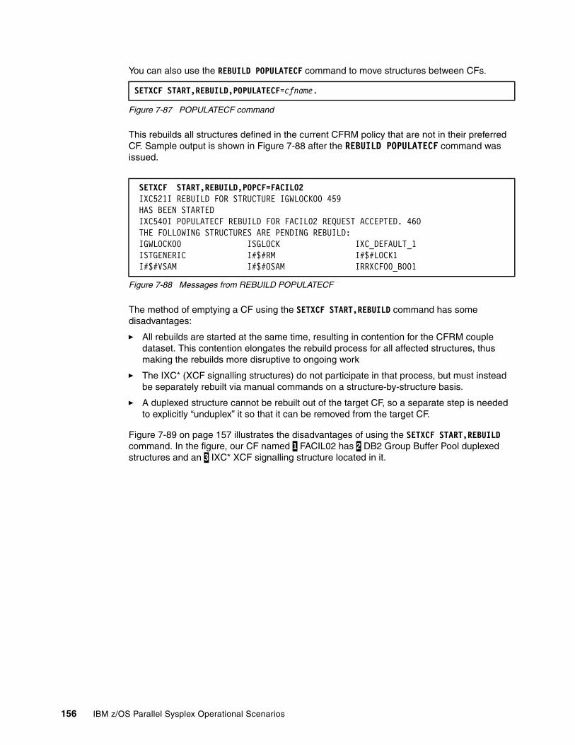
You can also use the REBUILD POPULATECF command to move structures between CFs.
Figure 7-87 POPULATECF command
This rebuilds all structures defined in the current CFRM policy that are not in their preferred CF. Sample output is shown in Figure 7-88 after the REBUILD POPULATECF command was issued.
Figure 7-88 Messages from REBUILD POPULATECF
The method of emptying a CF using the SETXCF START,REBUILD command has some disadvantages:
� All rebuilds are started at the same time, resulting in contention for the CFRM couple dataset. This contention elongates the rebuild process for all affected structures, thus making the rebuilds more disruptive to ongoing work
� The IXC* (XCF signalling structures) do not participate in that process, but must instead be separately rebuilt via manual commands on a structure-by-structure basis.
� A duplexed structure cannot be rebuilt out of the target CF, so a separate step is needed to explicitly “unduplex” it so that it can be removed from the target CF.
Figure 7-89 on page 157 illustrates the disadvantages of using the SETXCF START,REBUILD command. In the figure, our CF named 1 FACIL02 has 2 DB2 Group Buffer Pool duplexed structures and an 3 IXC* XCF signalling structure located in it.
SETXCF START,REBUILD,POPULATECF=cfname.
SETXCF START,REBUILD,POPCF=FACIL02 IXC521I REBUILD FOR STRUCTURE IGWLOCK00 459 HAS BEEN STARTED IXC540I POPULATECF REBUILD FOR FACIL02 REQUEST ACCEPTED. 460 THE FOLLOWING STRUCTURES ARE PENDING REBUILD: IGWLOCK00 ISGLOCK IXC_DEFAULT_1 ISTGENERIC I#$#RM I#$#LOCK1 I#$#VSAM I#$#OSAM IRRXCF00_B001
156 IBM z/OS Parallel Sysplex Operational Scenarios
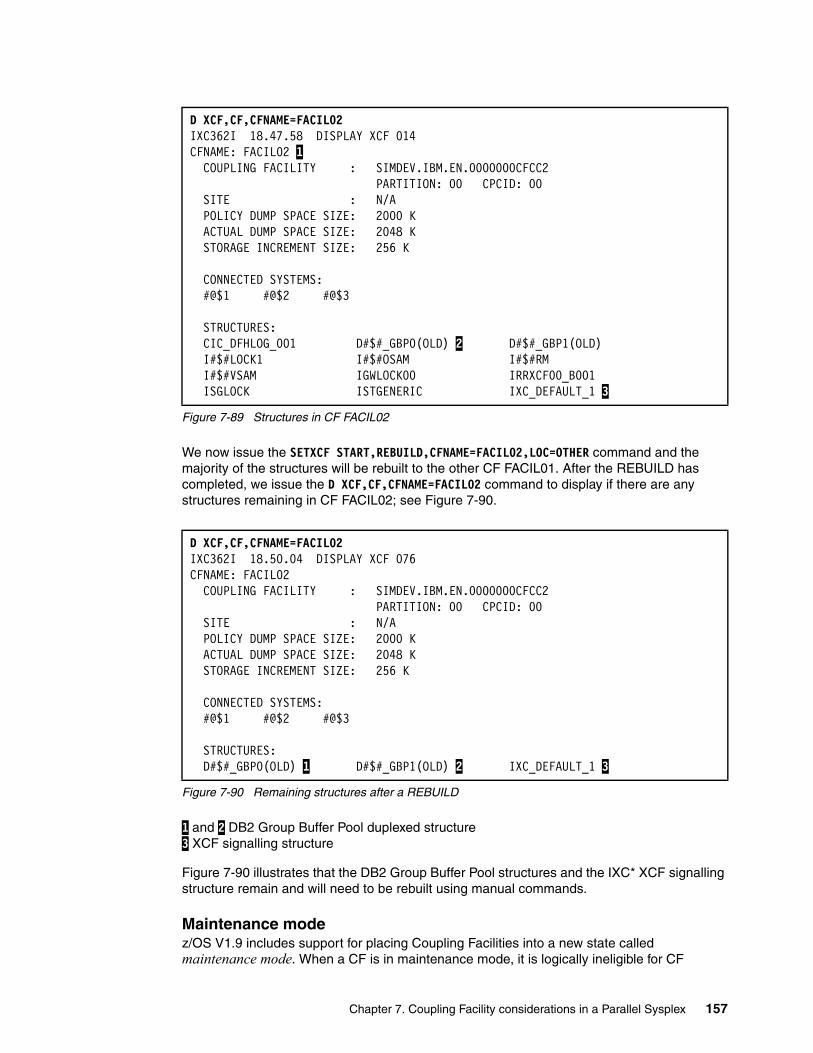
Figure 7-89 Structures in CF FACIL02
We now issue the SETXCF START,REBUILD,CFNAME=FACIL02,LOC=OTHER command and the majority of the structures will be rebuilt to the other CF FACIL01. After the REBUILD has completed, we issue the D XCF,CF,CFNAME=FACIL02 command to display if there are any structures remaining in CF FACIL02; see Figure 7-90.
Figure 7-90 Remaining structures after a REBUILD
1 and 2 DB2 Group Buffer Pool duplexed structure 3 XCF signalling structure
Figure 7-90 illustrates that the DB2 Group Buffer Pool structures and the IXC* XCF signalling structure remain and will need to be rebuilt using manual commands.
Maintenance modez/OS V1.9 includes support for placing Coupling Facilities into a new state called maintenance mode. When a CF is in maintenance mode, it is logically ineligible for CF
D XCF,CF,CFNAME=FACIL02 IXC362I 18.47.58 DISPLAY XCF 014 CFNAME: FACIL02 1 COUPLING FACILITY : SIMDEV.IBM.EN.0000000CFCC2 PARTITION: 00 CPCID: 00 SITE : N/A POLICY DUMP SPACE SIZE: 2000 K ACTUAL DUMP SPACE SIZE: 2048 K STORAGE INCREMENT SIZE: 256 K CONNECTED SYSTEMS: #@$1 #@$2 #@$3 STRUCTURES: CIC_DFHLOG_001 D#$#_GBP0(OLD) 2 D#$#_GBP1(OLD) I#$#LOCK1 I#$#OSAM I#$#RM I#$#VSAM IGWLOCK00 IRRXCF00_B001 ISGLOCK ISTGENERIC IXC_DEFAULT_1 3
D XCF,CF,CFNAME=FACIL02 IXC362I 18.50.04 DISPLAY XCF 076 CFNAME: FACIL02 COUPLING FACILITY : SIMDEV.IBM.EN.0000000CFCC2 PARTITION: 00 CPCID: 00 SITE : N/A POLICY DUMP SPACE SIZE: 2000 K ACTUAL DUMP SPACE SIZE: 2048 K STORAGE INCREMENT SIZE: 256 K CONNECTED SYSTEMS: #@$1 #@$2 #@$3 STRUCTURES: D#$#_GBP0(OLD) 1 D#$#_GBP1(OLD) 2 IXC_DEFAULT_1 3
Chapter 7. Coupling Facility considerations in a Parallel Sysplex 157
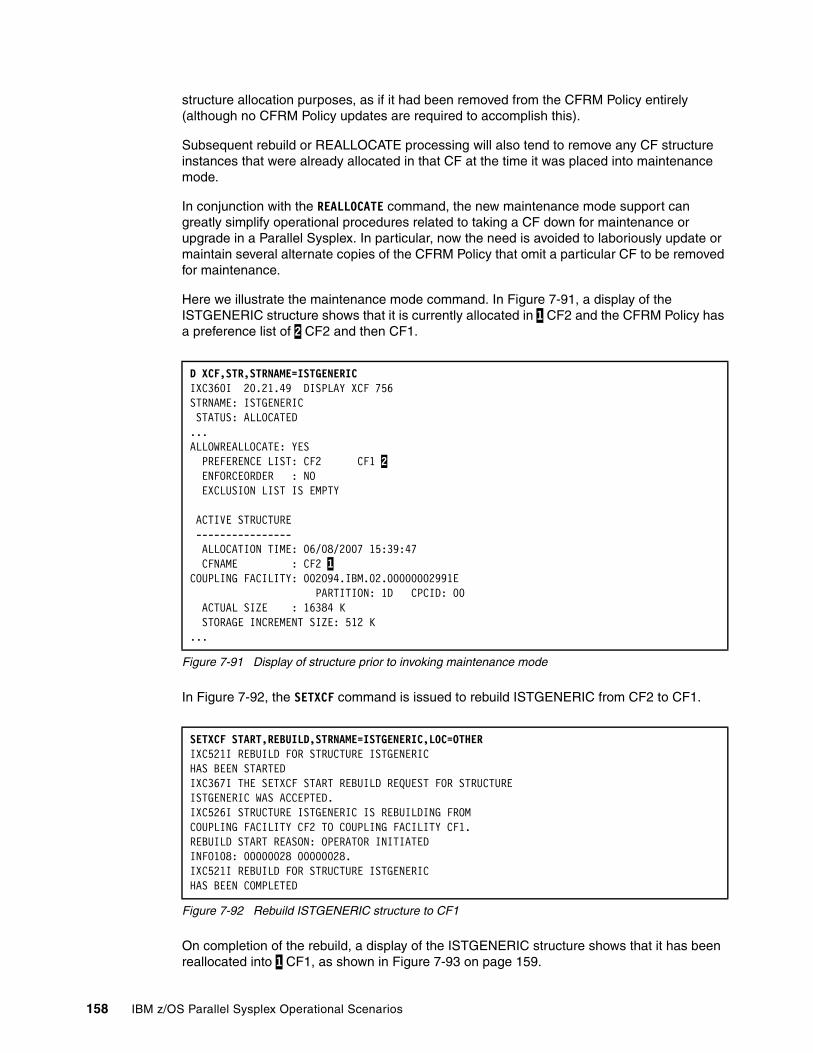
structure allocation purposes, as if it had been removed from the CFRM Policy entirely (although no CFRM Policy updates are required to accomplish this).
Subsequent rebuild or REALLOCATE processing will also tend to remove any CF structure instances that were already allocated in that CF at the time it was placed into maintenance mode.
In conjunction with the REALLOCATE command, the new maintenance mode support can greatly simplify operational procedures related to taking a CF down for maintenance or upgrade in a Parallel Sysplex. In particular, now the need is avoided to laboriously update or maintain several alternate copies of the CFRM Policy that omit a particular CF to be removed for maintenance.
Here we illustrate the maintenance mode command. In Figure 7-91, a display of the ISTGENERIC structure shows that it is currently allocated in 1 CF2 and the CFRM Policy has a preference list of 2 CF2 and then CF1.
Figure 7-91 Display of structure prior to invoking maintenance mode
In Figure 7-92, the SETXCF command is issued to rebuild ISTGENERIC from CF2 to CF1.
Figure 7-92 Rebuild ISTGENERIC structure to CF1
On completion of the rebuild, a display of the ISTGENERIC structure shows that it has been reallocated into 1 CF1, as shown in Figure 7-93 on page 159.
D XCF,STR,STRNAME=ISTGENERIC IXC360I 20.21.49 DISPLAY XCF 756 STRNAME: ISTGENERIC STATUS: ALLOCATED ...ALLOWREALLOCATE: YES PREFERENCE LIST: CF2 CF1 2 ENFORCEORDER : NO EXCLUSION LIST IS EMPTY ACTIVE STRUCTURE ---------------- ALLOCATION TIME: 06/08/2007 15:39:47 CFNAME : CF2 1COUPLING FACILITY: 002094.IBM.02.00000002991E PARTITION: 1D CPCID: 00 ACTUAL SIZE : 16384 K STORAGE INCREMENT SIZE: 512 K ...
SETXCF START,REBUILD,STRNAME=ISTGENERIC,LOC=OTHERIXC521I REBUILD FOR STRUCTURE ISTGENERIC HAS BEEN STARTED IXC367I THE SETXCF START REBUILD REQUEST FOR STRUCTURE ISTGENERIC WAS ACCEPTED. IXC526I STRUCTURE ISTGENERIC IS REBUILDING FROM COUPLING FACILITY CF2 TO COUPLING FACILITY CF1. REBUILD START REASON: OPERATOR INITIATED INFO108: 00000028 00000028. IXC521I REBUILD FOR STRUCTURE ISTGENERIC HAS BEEN COMPLETED
158 IBM z/OS Parallel Sysplex Operational Scenarios
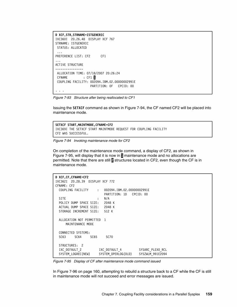
Figure 7-93 Structure after being reallocated to CF1
Issuing the SETXCF command as shown in Figure 7-94, the CF named CF2 will be placed into maintenance mode.
Figure 7-94 Invoking maintenance mode for CF2
On completion of the maintenance mode command, a display of CF2, as shown in Figure 7-95, will display that it is now in 1 maintenance mode and no allocations are permitted. Note that there are still 2 structures located in CF2, even though the CF is in maintenance mode.
Figure 7-95 Display of CF after maintenance mode command issued
In Figure 7-96 on page 160, attempting to rebuild a structure back to a CF while the CF is still in maintenance mode will not succeed and error messages are issued.
D XCF,STR,STRNAME=ISTGENERIC IXC360I 20.26.48 DISPLAY XCF 767 STRNAME: ISTGENERIC STATUS: ALLOCATED ... PREFERENCE LIST: CF2 CF1 ...ACTIVE STRUCTURE ---------------- ALLOCATION TIME: 07/18/2007 20:26:24 CFNAME : CF1 1 COUPLING FACILITY: 002094.IBM.02.00000002991E PARTITION: 0F CPCID: 00 . . .
SETXCF START,MAINTMODE,CFNAME=CF2IXC369I THE SETXCF START MAINTMODE REQUEST FOR COUPLING FACILITY CF2 WAS SUCCESSFUL.
D XCF,CF,CFNAME=CF2 IXC362I 20.28.39 DISPLAY XCF 772 CFNAME: CF2 COUPLING FACILITY : 002094.IBM.02.00000002991E PARTITION: 1D CPCID: 00 SITE : N/A POLICY DUMP SPACE SIZE: 2048 K ACTUAL DUMP SPACE SIZE: 2048 K STORAGE INCREMENT SIZE: 512 K ALLOCATION NOT PERMITTED 1 MAINTENANCE MODE CONNECTED SYSTEMS: SC63 SC64 SC65 SC70 STRUCTURES: 2 IXC_DEFAULT_2 IXC_DEFAULT_4 SYSARC_PLEX0_RCL SYSTEM_LOGREC(NEW) SYSTEM_OPERLOG(OLD) SYSZWLM_991E2094
Chapter 7. Coupling Facility considerations in a Parallel Sysplex 159
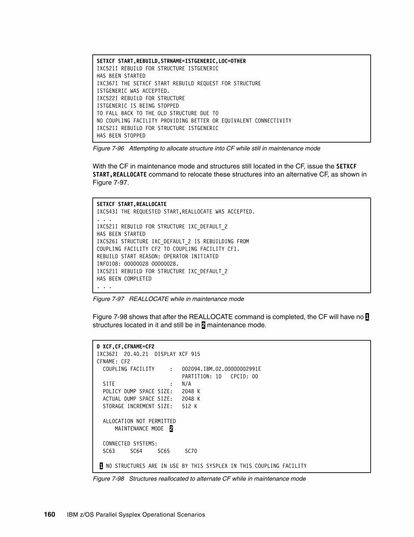
Figure 7-96 Attempting to allocate structure into CF while still in maintenance mode
With the CF in maintenance mode and structures still located in the CF, issue the SETXCF START,REALLOCATE command to relocate these structures into an alternative CF, as shown in Figure 7-97.
Figure 7-97 REALLOCATE while in maintenance mode
Figure 7-98 shows that after the REALLOCATE command is completed, the CF will have no 1 structures located in it and still be in 2 maintenance mode.
Figure 7-98 Structures reallocated to alternate CF while in maintenance mode
SETXCF START,REBUILD,STRNAME=ISTGENERIC,LOC=OTHERIXC521I REBUILD FOR STRUCTURE ISTGENERIC HAS BEEN STARTED IXC367I THE SETXCF START REBUILD REQUEST FOR STRUCTURE ISTGENERIC WAS ACCEPTED. IXC522I REBUILD FOR STRUCTURE ISTGENERIC IS BEING STOPPED TO FALL BACK TO THE OLD STRUCTURE DUE TO NO COUPLING FACILITY PROVIDING BETTER OR EQUIVALENT CONNECTIVITY IXC521I REBUILD FOR STRUCTURE ISTGENERIC HAS BEEN STOPPED
SETXCF START,REALLOCATE IXC543I THE REQUESTED START,REALLOCATE WAS ACCEPTED. . . .IXC521I REBUILD FOR STRUCTURE IXC_DEFAULT_2 HAS BEEN STARTED IXC526I STRUCTURE IXC_DEFAULT_2 IS REBUILDING FROM COUPLING FACILITY CF2 TO COUPLING FACILITY CF1. REBUILD START REASON: OPERATOR INITIATED INFO108: 00000028 00000028. IXC521I REBUILD FOR STRUCTURE IXC_DEFAULT_2 HAS BEEN COMPLETED . . .
D XCF,CF,CFNAME=CF2 IXC362I 20.40.21 DISPLAY XCF 915 CFNAME: CF2 COUPLING FACILITY : 002094.IBM.02.00000002991E PARTITION: 1D CPCID: 00 SITE : N/A POLICY DUMP SPACE SIZE: 2048 K ACTUAL DUMP SPACE SIZE: 2048 K STORAGE INCREMENT SIZE: 512 K ALLOCATION NOT PERMITTED MAINTENANCE MODE 2 CONNECTED SYSTEMS: SC63 SC64 SC65 SC70 1 NO STRUCTURES ARE IN USE BY THIS SYSPLEX IN THIS COUPLING FACILITY
160 IBM z/OS Parallel Sysplex Operational Scenarios

To remove maintenance mode from the CF, issue the SETXCF command as shown in Figure 7-99.
Figure 7-99 Turn off maintenance mode
7.8.2 Stopping structure rebuild
The rebuild process can be stopped by using the SETXCF STOP,REBUILD command or internally by the application; see Figure 7-100.
Figure 7-100 Stopping structure rebuild
7.8.3 Structure rebuild failure
There are occasions when an attempt to rebuild a structure fails. Structures that do not support rebuild are included in this category. Refer to Appendix B, “List of structures” on page 499 for a complete list of structures and their capability to rebuild.
If rebuild is not supported or fails, the connectors disconnect abnormally, indicating a recovery bind to the structure for which connectivity was lost. The connectors enter the failed persistent state.
Issue D XCF,STR,STRNM=strname; see Figure 7-101 on page 162.
SETXCF STOP,MAINTMODE,CFNAME=CF2IXC369I THE SETXCF STOP MAINTMODE REQUEST FOR COUPLING FACILITY CF2 WAS SUCCESSFUL.
SETXCF STOP,REBUILD,STRNM=IGWLOCK00 IXC522I REBUILD FOR STRUCTURE IGWLOCK00 IS BEING STOPPED DUE TO 718 REQUEST FROM AN OPERATOR IXC367I THE SETXCF STOP REBUILD REQUEST FOR STRUCTURE 719 IGWLOCK00 WAS ACCEPTED. IXL014I IXLCONN REQUEST FOR STRUCTURE IGWLOCK00 WAS SUCCESSFUL. 720 JOBNAME: SMSVSAM ASID: 000A CONNECTOR NAME: ZZZZZZZZ#@$3 CFNAME: FACIL02 IXC521I REBUILD FOR STRUCTURE IGWLOCK00 HAS BEEN STOPPED
Chapter 7. Coupling Facility considerations in a Parallel Sysplex 161
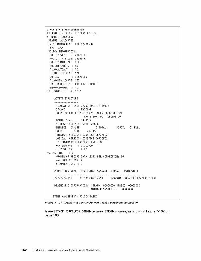
Figure 7-101 Displaying a structure with a failed persistent connection
Issue SETXCF FORCE,CON,CONNM=conname,STRNM=strname, as shown in Figure 7-102 on page 163.
D XCF,STR,STRNM=IGWLOCK00 IXC360I 19.30.05 DISPLAY XCF 538 STRNAME: IGWLOCK00 STATUS: ALLOCATED EVENT MANAGEMENT: POLICY-BASED TYPE: LOCK POLICY INFORMATION: POLICY SIZE : 20480 K POLICY INITSIZE: 14336 K POLICY MINSIZE : 0 K FULLTHRESHOLD : 80 ALLOWAUTOALT : NO REBUILD PERCENT: N/A DUPLEX : DISABLED ALLOWREALLOCATE: YES PREFERENCE LIST: FACIL02 FACIL01 ENFORCEORDER : NO EXCLUSION LIST IS EMPTY ACTIVE STRUCTURE ---------------- ALLOCATION TIME: 07/02/2007 18:49:15 CFNAME : FACIL01 COUPLING FACILITY: SIMDEV.IBM.EN.0000000CFCC1 PARTITION: 00 CPCID: 00 ACTUAL SIZE : 14336 K STORAGE INCREMENT SIZE: 256 K ENTRIES: IN-USE: 0 TOTAL: 36507, 0% FULL LOCKS: TOTAL: 2097152 PHYSICAL VERSION: C0D5FEC2 D6736F02 LOGICAL VERSION: C0D5FEC2 D6736F02 SYSTEM-MANAGED PROCESS LEVEL: 8 XCF GRPNAME : IXCLO000 DISPOSITION : KEEP ACCESS TIME : 0 NUMBER OF RECORD DATA LISTS PER CONNECTION: 16 MAX CONNECTIONS: 4 # CONNECTIONS : 3 CONNECTION NAME ID VERSION SYSNAME JOBNAME ASID STATE ---------------- -- -------- -------- -------- ---- -------- ZZZZZZZZ#@$1 03 00030077 #@$1 SMSVSAM 000A FAILED-PERSISTENT
DIAGNOSTIC INFORMATION: STRNUM: 00000000 STRSEQ: 00000000 MANAGER SYSTEM ID: 00000000 EVENT MANAGEMENT: POLICY-BASED
162 IBM z/OS Parallel Sysplex Operational Scenarios

Figure 7-102 Removing a connection
The message in Figure 7-102 was received because the IGWLOCK00 is a LOCK type structure, so removing a connection to it could result in undetected data loss.
7.8.4 Deleting persistent structures
After all failed persistent connectors are forced or the structure is forced, the structure may enter an in transition state and be ready for cleanup.
Figure 7-103 Structure in transition state
When the structure enters into this state, it means that the structure is a target for deletion. Depending on the application that owns the structure, you may need to restart the application for the structure to become allocated in the alternate CF. If this situation has been created by a CF failure, then when the failed CF is eventually restored, XES resolves this condition and this information is no longer displayed.
Another way to remove this condition is by removing the failed CF from the active CFRM policy. IPLing the z/OS images does not clear this condition. The number of connectors in message IXC360I (as shown in Displaying a Structure with FAILED-PERSISTENT Connections in Figure 7-81 on page 150) must be zero (0) before proceeding. If ACTIVE connectors exist, invoke recovery procedures for the connector, or CANCEL the connector's address space to make the connector disconnect from a structure. Issue SETXCF FORCE to delete the structure.
Figure 7-104 Forcing a structure
SETXCF FORCE,CON,CONNM=ZZZZZZZZ#@$1,STRNAME=IGWLOCK00 IXC354I THE SETXCF FORCE REQUEST FOR CONNECTION 638 ZZZZZZZZ#@$1 IN STRUCTURE IGWLOCK00 WAS REJECTED: FORCE CONNECTION NOT ALLOWED FOR PERSISTENT LOCK OR SERIALIZED LIST
IXC360I STRUCTURE IN TRANSITION----------------------- REASON IN TRANSITION: CONNECT OR DISCONNECT IN PROGRESS CFNAME : CFT1 NO SYSTEMS CONNECTED TO COUPLING FACILITY ALLOCATION TIME: 05/30/1997 15:43:52 COUPLING FACILITY: 009672.IBM.02.000000040104 PARTITION: 4 CPCID: 02 ACTUAL SIZE : N/A STORAGE INCREMENT SIZE: 256 K VERSION : AEBCBB20 64274704
SETXCF FORCE,STR,STRNM=IGWLOCK00IXC353I THE SETXCF FORCE REQUEST FOR STRUCTURE IGWLOCK00 WAS ACCEPTED: REQUEST WILL BE PROCESSED ASYNCHRONOUSLY
Note: If ACTIVE connectors exist, a message similar to the one shown in Figure 7-105 will be received.
Chapter 7. Coupling Facility considerations in a Parallel Sysplex 163

Figure 7-105 Active connections to a structure
If the structure remains, check the owner of the application and inform the appropriate support personnel.
IXC353I THE SETXCF FORCE REQUEST FOR STRUCTURE 677 IGWLOCK00 WAS REJECTED: STRUCTURE CONTAINS ACTIVE CONNECTIONS
164 IBM z/OS Parallel Sysplex Operational Scenarios

Chapter 8. Couple Data Set management
This chapter explains how to manage a Couple Data Set (CDS). It also introduces the commands required to manage Couple Data Sets in a Parallel Sysplex.
This chapter discusses:
� What Couple Data Sets are
� Couple Data Set configuration
� Commands needed to manage Couple Data Sets
8
© Copyright IBM Corp. 2009. All rights reserved. 165
8.1 Introduction to Couple Data Set management
Couple Data Sets (CDSs) are data sets that contain status and policy information for the sysplex. They provide a way for the systems in the sysplex to share this information so that they can manage the sysplex environment cooperatively.
There are seven different types of Couple Data Sets that could be used in a sysplex. Each type is associated with a different system component, such as WLM, System Logger, or XCF. These components use the Couple Data Sets as a repository of information. For example:
� Transient control information, such as the time of the latest system status update for each system in the sysplex
� More permanent control information, such as information about System Logger offload data sets
� Policy information, such as the WLM service class definitions used in the sysplex
The information held in the Couple Data Sets is critical for the continuous operation of the sysplex. If one of the system components loses access to its Couple Data Set, that component may fail. The impact on either a single system or the entire sysplex depends on which component loses access to its Couple Data Set, for example:
� If a system loses access to all the sysplex CDSs, it is unable to update its system status. As a result, it will be partitioned out of the sysplex.
� If a system loses access to all SFM CDSs, SFM is disabled across the entire sysplex.
When the first system is IPLed into a sysplex, it reads its Couple Data Set definition from the COUPLExx parmlib member. This system makes sure that the Couple Data Sets are available for use in the sysplex, and then it adds them to the sysplex. Every system that subsequently joins the sysplex must use the same Couple Data Sets.
After the systems are active in a sysplex, it is possible to change the Couple Data Set configuration of a sysplex dynamically. For additional information about Couple Data Sets, refer to z/OS V1R10.0 MVS Setting Up a Sysplex, SA22-7625.
8.2 The seven Couple Data Sets
You can have seven Couple Data Sets in a sysplex environment:
� Sysplex� ARM� BPXMCDS� CFRM� LOGR� SFM� WLM
Notice that the Couple Data Sets are named after the system components that use them. Not all of these components must be active in a Parallel Sysplex, however. The following list identifies which Couple Data Sets are mandatory and which ones are optional:
� In a Parallel Sysplex, the sysplex CDS and the CFRM CDS are mandatory because they describe the Parallel Sysplex environment you are running.
166 IBM z/OS Parallel Sysplex Operational Scenarios
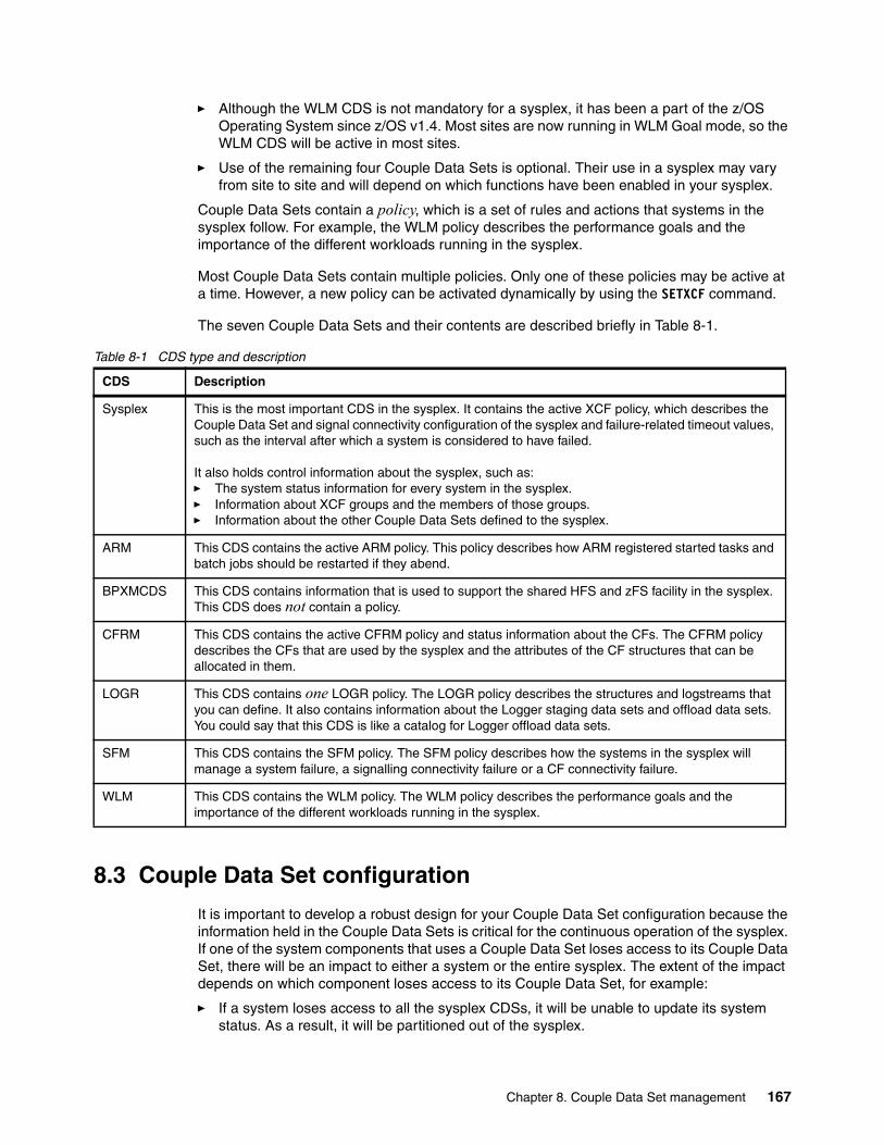
� Although the WLM CDS is not mandatory for a sysplex, it has been a part of the z/OS Operating System since z/OS v1.4. Most sites are now running in WLM Goal mode, so the WLM CDS will be active in most sites.
� Use of the remaining four Couple Data Sets is optional. Their use in a sysplex may vary from site to site and will depend on which functions have been enabled in your sysplex.
Couple Data Sets contain a policy, which is a set of rules and actions that systems in the sysplex follow. For example, the WLM policy describes the performance goals and the importance of the different workloads running in the sysplex.
Most Couple Data Sets contain multiple policies. Only one of these policies may be active at a time. However, a new policy can be activated dynamically by using the SETXCF command.
The seven Couple Data Sets and their contents are described briefly in Table 8-1.
Table 8-1 CDS type and description
8.3 Couple Data Set configuration
It is important to develop a robust design for your Couple Data Set configuration because the information held in the Couple Data Sets is critical for the continuous operation of the sysplex. If one of the system components that uses a Couple Data Set loses access to its Couple Data Set, there will be an impact to either a system or the entire sysplex. The extent of the impact depends on which component loses access to its Couple Data Set, for example:
� If a system loses access to all the sysplex CDSs, it will be unable to update its system status. As a result, it will be partitioned out of the sysplex.
CDS Description
Sysplex This is the most important CDS in the sysplex. It contains the active XCF policy, which describes the Couple Data Set and signal connectivity configuration of the sysplex and failure-related timeout values, such as the interval after which a system is considered to have failed.
It also holds control information about the sysplex, such as:� The system status information for every system in the sysplex. � Information about XCF groups and the members of those groups.� Information about the other Couple Data Sets defined to the sysplex.
ARM This CDS contains the active ARM policy. This policy describes how ARM registered started tasks and batch jobs should be restarted if they abend.
BPXMCDS This CDS contains information that is used to support the shared HFS and zFS facility in the sysplex. This CDS does not contain a policy.
CFRM This CDS contains the active CFRM policy and status information about the CFs. The CFRM policy describes the CFs that are used by the sysplex and the attributes of the CF structures that can be allocated in them.
LOGR This CDS contains one LOGR policy. The LOGR policy describes the structures and logstreams that you can define. It also contains information about the Logger staging data sets and offload data sets. You could say that this CDS is like a catalog for Logger offload data sets.
SFM This CDS contains the SFM policy. The SFM policy describes how the systems in the sysplex will manage a system failure, a signalling connectivity failure or a CF connectivity failure.
WLM This CDS contains the WLM policy. The WLM policy describes the performance goals and the importance of the different workloads running in the sysplex.
Chapter 8. Couple Data Set management 167
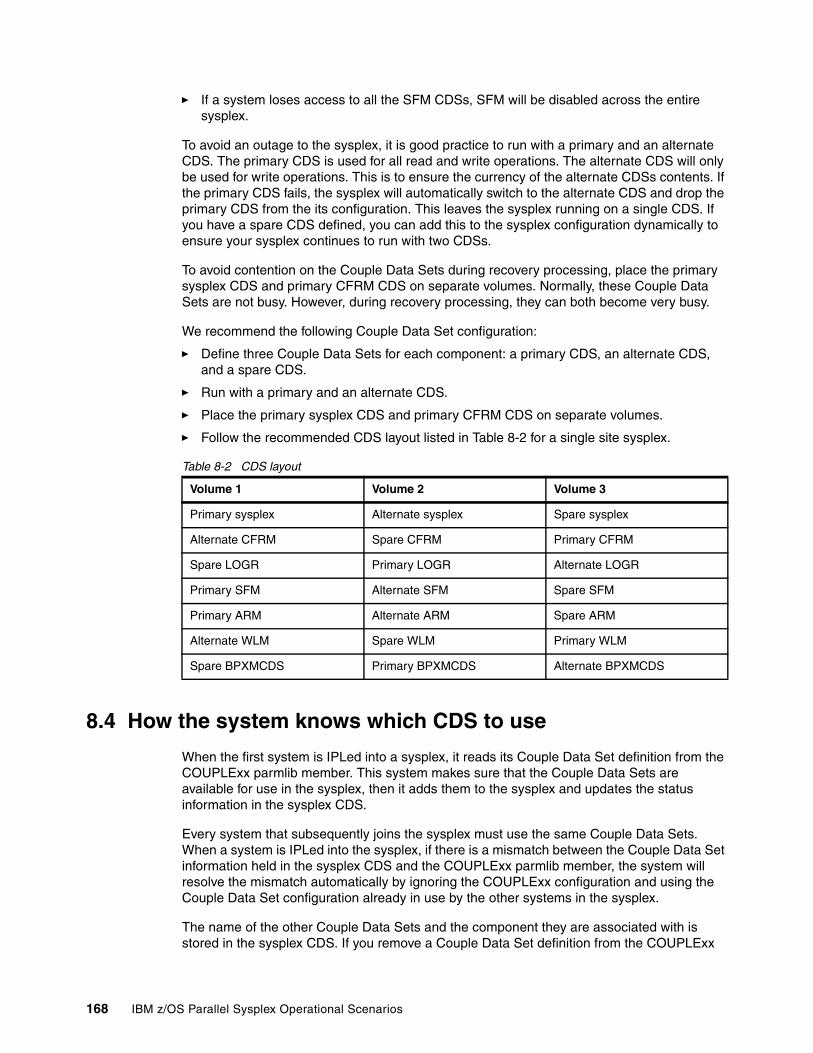
� If a system loses access to all the SFM CDSs, SFM will be disabled across the entire sysplex.
To avoid an outage to the sysplex, it is good practice to run with a primary and an alternate CDS. The primary CDS is used for all read and write operations. The alternate CDS will only be used for write operations. This is to ensure the currency of the alternate CDSs contents. If the primary CDS fails, the sysplex will automatically switch to the alternate CDS and drop the primary CDS from the its configuration. This leaves the sysplex running on a single CDS. If you have a spare CDS defined, you can add this to the sysplex configuration dynamically to ensure your sysplex continues to run with two CDSs.
To avoid contention on the Couple Data Sets during recovery processing, place the primary sysplex CDS and primary CFRM CDS on separate volumes. Normally, these Couple Data Sets are not busy. However, during recovery processing, they can both become very busy.
We recommend the following Couple Data Set configuration:
� Define three Couple Data Sets for each component: a primary CDS, an alternate CDS, and a spare CDS.
� Run with a primary and an alternate CDS.
� Place the primary sysplex CDS and primary CFRM CDS on separate volumes.
� Follow the recommended CDS layout listed in Table 8-2 for a single site sysplex.
Table 8-2 CDS layout
8.4 How the system knows which CDS to use
When the first system is IPLed into a sysplex, it reads its Couple Data Set definition from the COUPLExx parmlib member. This system makes sure that the Couple Data Sets are available for use in the sysplex, then it adds them to the sysplex and updates the status information in the sysplex CDS.
Every system that subsequently joins the sysplex must use the same Couple Data Sets. When a system is IPLed into the sysplex, if there is a mismatch between the Couple Data Set information held in the sysplex CDS and the COUPLExx parmlib member, the system will resolve the mismatch automatically by ignoring the COUPLExx configuration and using the Couple Data Set configuration already in use by the other systems in the sysplex.
The name of the other Couple Data Sets and the component they are associated with is stored in the sysplex CDS. If you remove a Couple Data Set definition from the COUPLExx
Volume 1 Volume 2 Volume 3
Primary sysplex Alternate sysplex Spare sysplex
Alternate CFRM Spare CFRM Primary CFRM
Spare LOGR Primary LOGR Alternate LOGR
Primary SFM Alternate SFM Spare SFM
Primary ARM Alternate ARM Spare ARM
Alternate WLM Spare WLM Primary WLM
Spare BPXMCDS Primary BPXMCDS Alternate BPXMCDS
168 IBM z/OS Parallel Sysplex Operational Scenarios

parmlib member, this information is not deleted from the sysplex CDS. Instead, this information remains in the sysplex CDS until it is replaced by a new definition.
After the systems are active in a sysplex, it is possible to change the Couple Data Set configuration dynamically by using the SETXCF COUPLE command.
8.5 Managing CDSs
The following commands can be used to manage Couple Data Sets. For additional information about these commands, see z/OS MVS System Commands, SA22-7627.
8.5.1 Displaying CDSs
To display basic information about all the CDSs in the sysplex, use the command:
D XCF,COUPLE,TYPE=ALL
An example of the output from this command is shown in Figure 8-1 on page 170. Points of interest in the output are:
� The sysplex CDS is always displayed first and the other active CDSs are displayed in alphabetical order of the system components that use them. There is no mandatory naming standard for Couple Data Sets. In this example, the primary sysplex CDS is called SYS1.XCF.CDS01.
� There is a line of status information after each type of CDS. This status indicates which systems have access to both the primary and alternate CDS. The exception is the sysplex CDS, because all systems in the sysplex must use the same sysplex CDS. This does not refer to the status of a policy being used in the sysplex for that type of CDS.
Chapter 8. Couple Data Set management 169
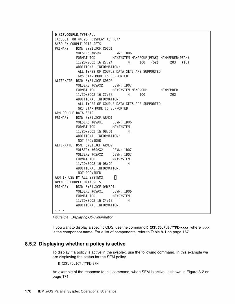
Figure 8-1 Displaying CDS information
If you want to display a specific CDS, use the command D XCF,COUPLE,TYPE=xxxx, where xxxx is the component name. For a list of components, refer to Table 8-1 on page 167.
8.5.2 Displaying whether a policy is active
To display if a policy is active in the sysplex, use the following command. In this example we are displaying the status for the SFM policy.
D XCF,POLICY,TYPE=SFM
An example of the response to this command, when SFM is active, is shown in Figure 8-2 on page 171.
D XCF,COUPLE,TYPE=ALL IXC358I 00.44.28 DISPLAY XCF 877 SYSPLEX COUPLE DATA SETS PRIMARY DSN: SYS1.XCF.CDS01 VOLSER: #@$#X1 DEVN: 1D06 FORMAT TOD MAXSYSTEM MAXGROUP(PEAK) MAXMEMBER(PEAK) 11/20/2002 16:27:24 4 100 (52) 203 (18) ADDITIONAL INFORMATION: ALL TYPES OF COUPLE DATA SETS ARE SUPPORTED GRS STAR MODE IS SUPPORTED ALTERNATE DSN: SYS1.XCF.CDS02 VOLSER: #@$#X2 DEVN: 1D07 FORMAT TOD MAXSYSTEM MAXGROUP MAXMEMBER 11/20/2002 16:27:28 4 100 203 ADDITIONAL INFORMATION: ALL TYPES OF COUPLE DATA SETS ARE SUPPORTED GRS STAR MODE IS SUPPORTED ARM COUPLE DATA SETS PRIMARY DSN: SYS1.XCF.ARM01 VOLSER: #@$#X1 DEVN: 1D06 FORMAT TOD MAXSYSTEM 11/20/2002 15:08:01 4 ADDITIONAL INFORMATION: NOT PROVIDED ALTERNATE DSN: SYS1.XCF.ARM02 VOLSER: #@$#X2 DEVN: 1D07 VOLSER: #@$#X2 DEVN: 1D07 FORMAT TOD MAXSYSTEM 11/20/2002 15:08:04 4 ADDITIONAL INFORMATION: NOT PROVIDED ARM IN USE BY ALL SYSTEMS 1 BPXMCDS COUPLE DATA SETS PRIMARY DSN: SYS1.XCF.OMVS01 VOLSER: #@$#X1 DEVN: 1D06 FORMAT TOD MAXSYSTEM 11/20/2002 15:24:18 4 ADDITIONAL INFORMATION: . . .
170 IBM z/OS Parallel Sysplex Operational Scenarios
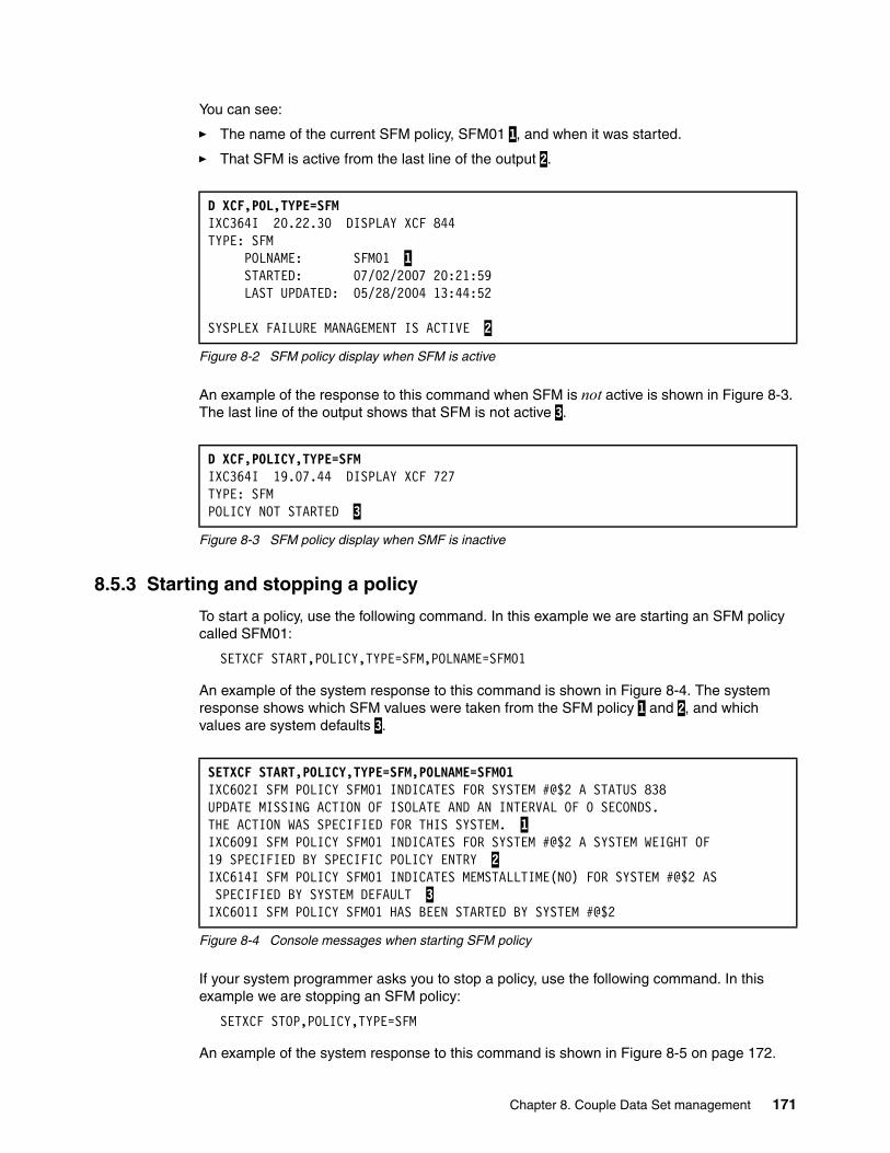
You can see:
� The name of the current SFM policy, SFM01 1, and when it was started.
� That SFM is active from the last line of the output 2.
Figure 8-2 SFM policy display when SFM is active
An example of the response to this command when SFM is not active is shown in Figure 8-3. The last line of the output shows that SFM is not active 3.
Figure 8-3 SFM policy display when SMF is inactive
8.5.3 Starting and stopping a policy
To start a policy, use the following command. In this example we are starting an SFM policy called SFM01:
SETXCF START,POLICY,TYPE=SFM,POLNAME=SFM01
An example of the system response to this command is shown in Figure 8-4. The system response shows which SFM values were taken from the SFM policy 1 and 2, and which values are system defaults 3.
Figure 8-4 Console messages when starting SFM policy
If your system programmer asks you to stop a policy, use the following command. In this example we are stopping an SFM policy:
SETXCF STOP,POLICY,TYPE=SFM
An example of the system response to this command is shown in Figure 8-5 on page 172.
D XCF,POL,TYPE=SFM IXC364I 20.22.30 DISPLAY XCF 844 TYPE: SFM POLNAME: SFM01 1 STARTED: 07/02/2007 20:21:59 LAST UPDATED: 05/28/2004 13:44:52 SYSPLEX FAILURE MANAGEMENT IS ACTIVE 2
D XCF,POLICY,TYPE=SFM IXC364I 19.07.44 DISPLAY XCF 727 TYPE: SFM POLICY NOT STARTED 3
SETXCF START,POLICY,TYPE=SFM,POLNAME=SFM01 IXC602I SFM POLICY SFM01 INDICATES FOR SYSTEM #@$2 A STATUS 838 UPDATE MISSING ACTION OF ISOLATE AND AN INTERVAL OF 0 SECONDS. THE ACTION WAS SPECIFIED FOR THIS SYSTEM. 1 IXC609I SFM POLICY SFM01 INDICATES FOR SYSTEM #@$2 A SYSTEM WEIGHT OF 19 SPECIFIED BY SPECIFIC POLICY ENTRY 2 IXC614I SFM POLICY SFM01 INDICATES MEMSTALLTIME(NO) FOR SYSTEM #@$2 AS SPECIFIED BY SYSTEM DEFAULT 3 IXC601I SFM POLICY SFM01 HAS BEEN STARTED BY SYSTEM #@$2
Chapter 8. Couple Data Set management 171
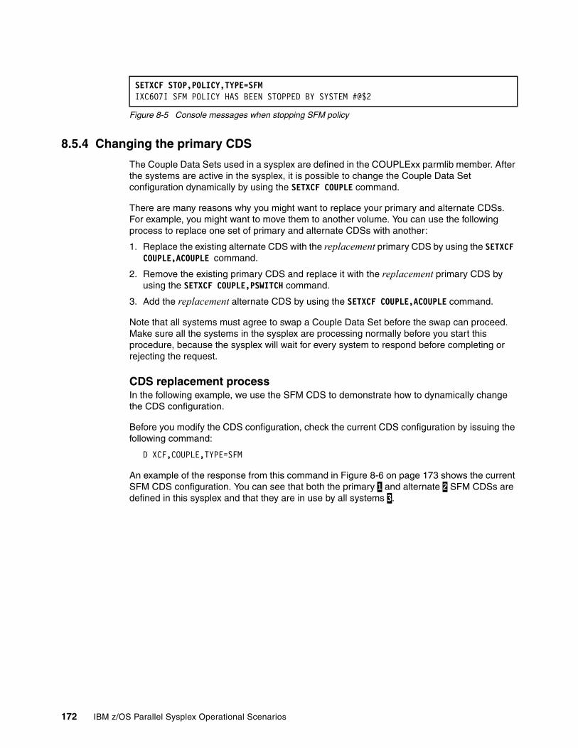
Figure 8-5 Console messages when stopping SFM policy
8.5.4 Changing the primary CDS
The Couple Data Sets used in a sysplex are defined in the COUPLExx parmlib member. After the systems are active in the sysplex, it is possible to change the Couple Data Set configuration dynamically by using the SETXCF COUPLE command.
There are many reasons why you might want to replace your primary and alternate CDSs. For example, you might want to move them to another volume. You can use the following process to replace one set of primary and alternate CDSs with another:
1. Replace the existing alternate CDS with the replacement primary CDS by using the SETXCF COUPLE,ACOUPLE command.
2. Remove the existing primary CDS and replace it with the replacement primary CDS by using the SETXCF COUPLE,PSWITCH command.
3. Add the replacement alternate CDS by using the SETXCF COUPLE,ACOUPLE command.
Note that all systems must agree to swap a Couple Data Set before the swap can proceed. Make sure all the systems in the sysplex are processing normally before you start this procedure, because the sysplex will wait for every system to respond before completing or rejecting the request.
CDS replacement processIn the following example, we use the SFM CDS to demonstrate how to dynamically change the CDS configuration.
Before you modify the CDS configuration, check the current CDS configuration by issuing the following command:
D XCF,COUPLE,TYPE=SFM
An example of the response from this command in Figure 8-6 on page 173 shows the current SFM CDS configuration. You can see that both the primary 1 and alternate 2 SFM CDSs are defined in this sysplex and that they are in use by all systems 3.
SETXCF STOP,POLICY,TYPE=SFM IXC607I SFM POLICY HAS BEEN STOPPED BY SYSTEM #@$2
172 IBM z/OS Parallel Sysplex Operational Scenarios
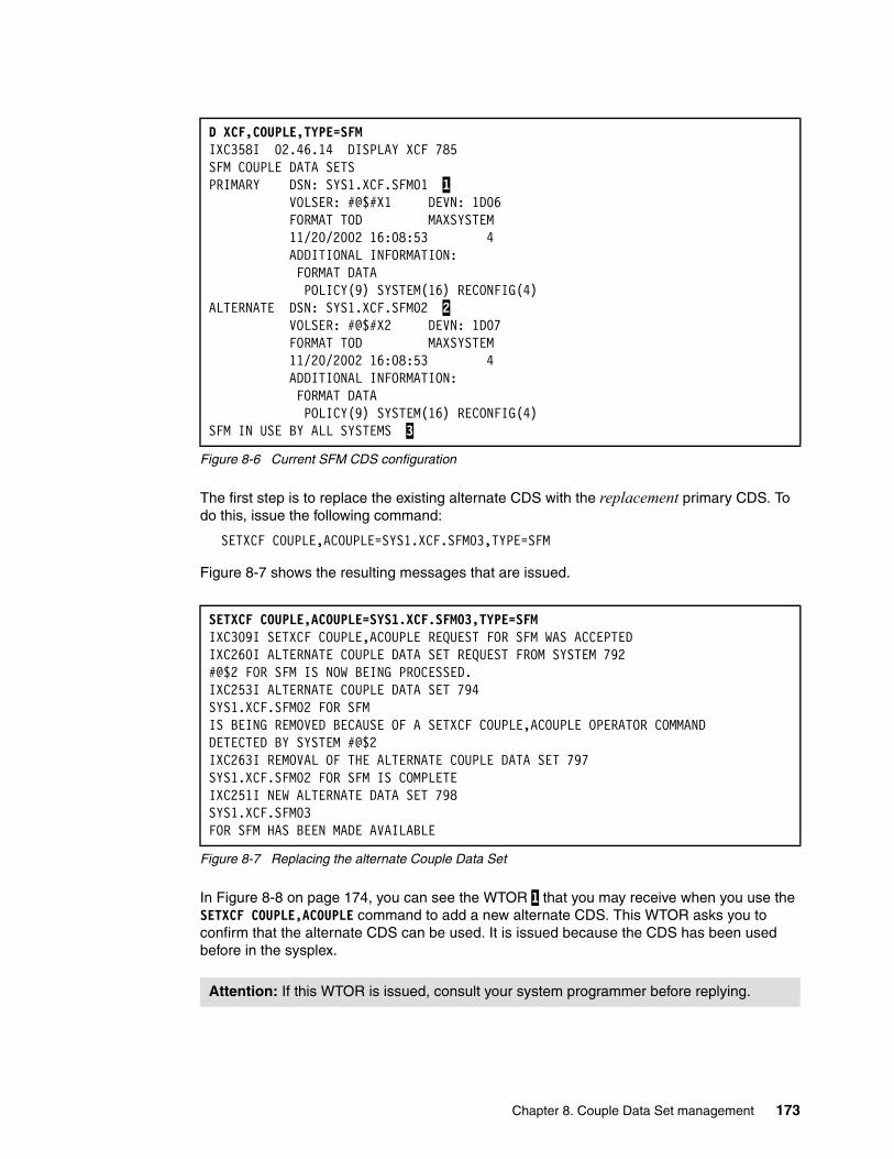
Figure 8-6 Current SFM CDS configuration
The first step is to replace the existing alternate CDS with the replacement primary CDS. To do this, issue the following command:
SETXCF COUPLE,ACOUPLE=SYS1.XCF.SFM03,TYPE=SFM
Figure 8-7 shows the resulting messages that are issued.
Figure 8-7 Replacing the alternate Couple Data Set
In Figure 8-8 on page 174, you can see the WTOR 1 that you may receive when you use the SETXCF COUPLE,ACOUPLE command to add a new alternate CDS. This WTOR asks you to confirm that the alternate CDS can be used. It is issued because the CDS has been used before in the sysplex.
D XCF,COUPLE,TYPE=SFM IXC358I 02.46.14 DISPLAY XCF 785 SFM COUPLE DATA SETS PRIMARY DSN: SYS1.XCF.SFM01 1 VOLSER: #@$#X1 DEVN: 1D06 FORMAT TOD MAXSYSTEM 11/20/2002 16:08:53 4 ADDITIONAL INFORMATION: FORMAT DATA POLICY(9) SYSTEM(16) RECONFIG(4) ALTERNATE DSN: SYS1.XCF.SFM02 2 VOLSER: #@$#X2 DEVN: 1D07 FORMAT TOD MAXSYSTEM 11/20/2002 16:08:53 4 ADDITIONAL INFORMATION: FORMAT DATA POLICY(9) SYSTEM(16) RECONFIG(4) SFM IN USE BY ALL SYSTEMS 3
SETXCF COUPLE,ACOUPLE=SYS1.XCF.SFM03,TYPE=SFM IXC309I SETXCF COUPLE,ACOUPLE REQUEST FOR SFM WAS ACCEPTED IXC260I ALTERNATE COUPLE DATA SET REQUEST FROM SYSTEM 792 #@$2 FOR SFM IS NOW BEING PROCESSED. IXC253I ALTERNATE COUPLE DATA SET 794 SYS1.XCF.SFM02 FOR SFM IS BEING REMOVED BECAUSE OF A SETXCF COUPLE,ACOUPLE OPERATOR COMMAND DETECTED BY SYSTEM #@$2 IXC263I REMOVAL OF THE ALTERNATE COUPLE DATA SET 797 SYS1.XCF.SFM02 FOR SFM IS COMPLETE IXC251I NEW ALTERNATE DATA SET 798 SYS1.XCF.SFM03 FOR SFM HAS BEEN MADE AVAILABLE
Attention: If this WTOR is issued, consult your system programmer before replying.
Chapter 8. Couple Data Set management 173
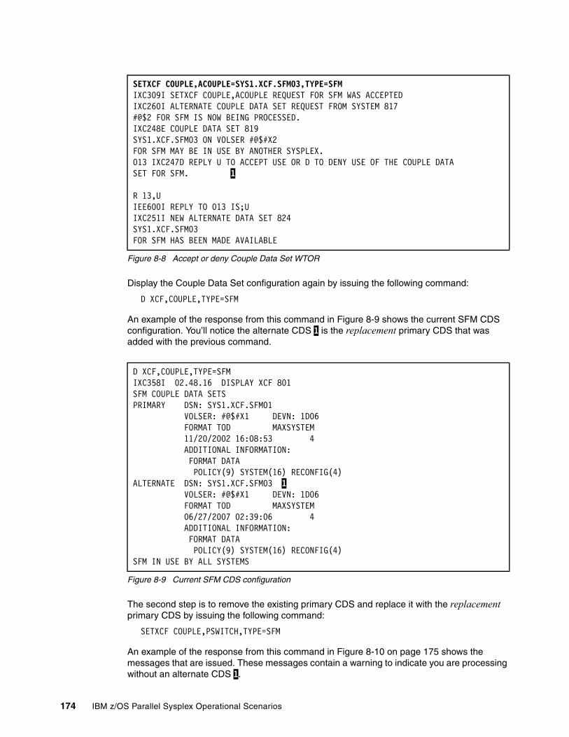
Figure 8-8 Accept or deny Couple Data Set WTOR
Display the Couple Data Set configuration again by issuing the following command:
D XCF,COUPLE,TYPE=SFM
An example of the response from this command in Figure 8-9 shows the current SFM CDS configuration. You’ll notice the alternate CDS 1 is the replacement primary CDS that was added with the previous command.
Figure 8-9 Current SFM CDS configuration
The second step is to remove the existing primary CDS and replace it with the replacement primary CDS by issuing the following command:
SETXCF COUPLE,PSWITCH,TYPE=SFM
An example of the response from this command in Figure 8-10 on page 175 shows the messages that are issued. These messages contain a warning to indicate you are processing without an alternate CDS 1.
SETXCF COUPLE,ACOUPLE=SYS1.XCF.SFM03,TYPE=SFM IXC309I SETXCF COUPLE,ACOUPLE REQUEST FOR SFM WAS ACCEPTED IXC260I ALTERNATE COUPLE DATA SET REQUEST FROM SYSTEM 817 #@$2 FOR SFM IS NOW BEING PROCESSED. IXC248E COUPLE DATA SET 819 SYS1.XCF.SFM03 ON VOLSER #@$#X2 FOR SFM MAY BE IN USE BY ANOTHER SYSPLEX. 013 IXC247D REPLY U TO ACCEPT USE OR D TO DENY USE OF THE COUPLE DATA SET FOR SFM. 1 R 13,U IEE600I REPLY TO 013 IS;U IXC251I NEW ALTERNATE DATA SET 824 SYS1.XCF.SFM03 FOR SFM HAS BEEN MADE AVAILABLE
D XCF,COUPLE,TYPE=SFM IXC358I 02.48.16 DISPLAY XCF 801 SFM COUPLE DATA SETS PRIMARY DSN: SYS1.XCF.SFM01 VOLSER: #@$#X1 DEVN: 1D06 FORMAT TOD MAXSYSTEM 11/20/2002 16:08:53 4 ADDITIONAL INFORMATION: FORMAT DATA POLICY(9) SYSTEM(16) RECONFIG(4) ALTERNATE DSN: SYS1.XCF.SFM03 1 VOLSER: #@$#X1 DEVN: 1D06 FORMAT TOD MAXSYSTEM 06/27/2007 02:39:06 4 ADDITIONAL INFORMATION: FORMAT DATA POLICY(9) SYSTEM(16) RECONFIG(4) SFM IN USE BY ALL SYSTEMS
174 IBM z/OS Parallel Sysplex Operational Scenarios

Figure 8-10 Replacing the primary Couple Data Set
Display the Couple Data Set configuration again by issuing the following command:
D XCF,COUPLE,TYPE=SFM
An example of the response from this command in Figure 8-11 shows the current SFM CDS configuration. Notice that there is no alternate CDS in the configuration.
Figure 8-11 Current SFM CDS configuration
The final step is add the replacement alternate CDS by issuing the following command:
SETXCF COUPLE,ACOUPLE=SYS1.XCF.SFM04,TYPE=SFM
An example of the response from this command in Figure 8-12 shows the messages that are issued.
Figure 8-12 Replacing the alternate Couple Data Set
Display the Couple Data Set configuration again by issuing the following command:
D XCF,COUPLE,TYPE=SFM
SETXCF COUPLE,PSWITCH,TYPE=SFM IXC309I SETXCF COUPLE,PSWITCH REQUEST FOR SFM WAS ACCEPTED IXC257I PRIMARY COUPLE DATA SET 805 SYS1.XCF.SFM01 FOR SFM IS BEING REPLACED BY SYS1.XCF.SFM03 DUE TO OPERATOR REQUEST IXC263I REMOVAL OF THE PRIMARY COUPLE DATA SET 808 SYS1.XCF.SFM01 FOR SFM IS COMPLETE IXC267E PROCESSING WITHOUT AN ALTERNATE 809 COUPLE DATA SET FOR SFM. ISSUE SETXCF COMMAND TO ACTIVATE A NEW ALTERNATE 1.
D XCF,COUPLE,TYPE=SFM IXC358I 02.49.30 DISPLAY XCF 811 SFM COUPLE DATA SETS PRIMARY DSN: SYS1.XCF.SFM03 VOLSER: #@$#X1 DEVN: 1D06 FORMAT TOD MAXSYSTEM 06/27/2007 02:39:06 4 ADDITIONAL INFORMATION: FORMAT DATA POLICY(9) SYSTEM(16) RECONFIG(4) SFM IN USE BY ALL SYSTEMS
SETXCF COUPLE,ACOUPLE=SYS1.XCF.SFM04,TYPE=SFM IXC309I SETXCF COUPLE,ACOUPLE REQUEST FOR SFM WAS ACCEPTEDIXC260I ALTERNATE COUPLE DATA SET REQUEST FROM SYSTEM 183 #@$2 FOR SFM IS NOW BEING PROCESSED. IXC251I NEW ALTERNATE DATA SET 185 SYS1.XCF.SFM04 FOR SFM HAS BEEN MADE AVAILABLE
Chapter 8. Couple Data Set management 175
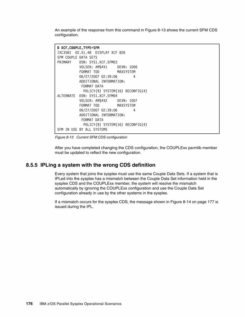
An example of the response from this command in Figure 8-13 shows the current SFM CDS configuration.
Figure 8-13 Current SFM CDS configuration
After you have completed changing the CDS configuration, the COUPLExx parmlib member must be updated to reflect the new configuration.
8.5.5 IPLing a system with the wrong CDS definition
Every system that joins the sysplex must use the same Couple Data Sets. If a system that is IPLed into the sysplex has a mismatch between the Couple Data Set information held in the sysplex CDS and the COUPLExx member, the system will resolve the mismatch automatically by ignoring the COUPLExx configuration and use the Couple Data Set configuration already in use by the other systems in the sysplex.
If a mismatch occurs for the sysplex CDS, the message shown in Figure 8-14 on page 177 is issued during the IPL.
D XCF,COUPLE,TYPE=SFM IXC358I 02.51.48 DISPLAY XCF 826 SFM COUPLE DATA SETS PRIMARY DSN: SYS1.XCF.SFM03 VOLSER: #@$#X1 DEVN: 1D06 FORMAT TOD MAXSYSTEM 06/27/2007 02:39:06 4 ADDITIONAL INFORMATION: FORMAT DATA POLICY(9) SYSTEM(16) RECONFIG(4) ALTERNATE DSN: SYS1.XCF.SFM04 VOLSER: #@$#X2 DEVN: 1D07 FORMAT TOD MAXSYSTEM 06/27/2007 02:39:06 4 ADDITIONAL INFORMATION: FORMAT DATA POLICY(9) SYSTEM(16) RECONFIG(4) SFM IN USE BY ALL SYSTEMS
176 IBM z/OS Parallel Sysplex Operational Scenarios
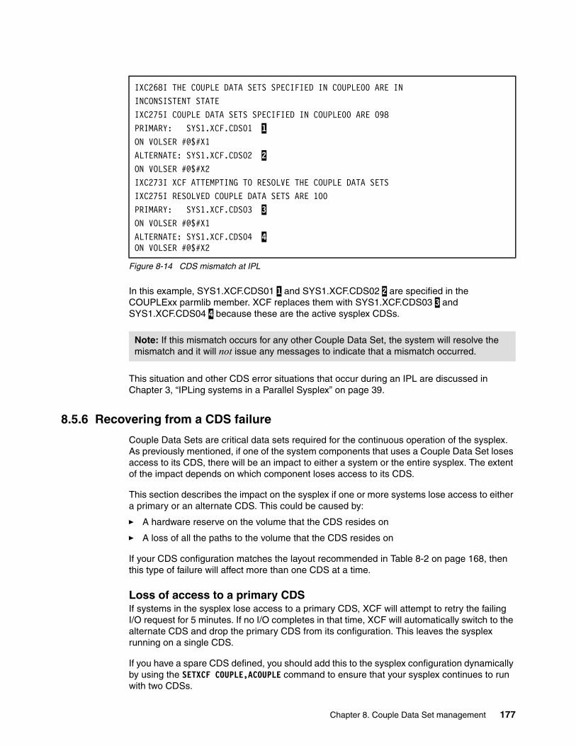
Figure 8-14 CDS mismatch at IPL
In this example, SYS1.XCF.CDS01 1 and SYS1.XCF.CDS02 2 are specified in the COUPLExx parmlib member. XCF replaces them with SYS1.XCF.CDS03 3 and SYS1.XCF.CDS04 4 because these are the active sysplex CDSs.
This situation and other CDS error situations that occur during an IPL are discussed in Chapter 3, “IPLing systems in a Parallel Sysplex” on page 39.
8.5.6 Recovering from a CDS failure
Couple Data Sets are critical data sets required for the continuous operation of the sysplex. As previously mentioned, if one of the system components that uses a Couple Data Set loses access to its CDS, there will be an impact to either a system or the entire sysplex. The extent of the impact depends on which component loses access to its CDS.
This section describes the impact on the sysplex if one or more systems lose access to either a primary or an alternate CDS. This could be caused by:
� A hardware reserve on the volume that the CDS resides on
� A loss of all the paths to the volume that the CDS resides on
If your CDS configuration matches the layout recommended in Table 8-2 on page 168, then this type of failure will affect more than one CDS at a time.
Loss of access to a primary CDSIf systems in the sysplex lose access to a primary CDS, XCF will attempt to retry the failing I/O request for 5 minutes. If no I/O completes in that time, XCF will automatically switch to the alternate CDS and drop the primary CDS from its configuration. This leaves the sysplex running on a single CDS.
If you have a spare CDS defined, you should add this to the sysplex configuration dynamically by using the SETXCF COUPLE,ACOUPLE command to ensure that your sysplex continues to run with two CDSs.
IXC268I THE COUPLE DATA SETS SPECIFIED IN COUPLE00 ARE IN INCONSISTENT STATE IXC275I COUPLE DATA SETS SPECIFIED IN COUPLE00 ARE 098 PRIMARY: SYS1.XCF.CDS01 1 ON VOLSER #@$#X1 ALTERNATE: SYS1.XCF.CDS02 2 ON VOLSER #@$#X2 IXC273I XCF ATTEMPTING TO RESOLVE THE COUPLE DATA SETS IXC275I RESOLVED COUPLE DATA SETS ARE 100 PRIMARY: SYS1.XCF.CDS03 3 ON VOLSER #@$#X1 ALTERNATE: SYS1.XCF.CDS04 4 ON VOLSER #@$#X2
Note: If this mismatch occurs for any other Couple Data Set, the system will resolve the mismatch and it will not issue any messages to indicate that a mismatch occurred.
Chapter 8. Couple Data Set management 177
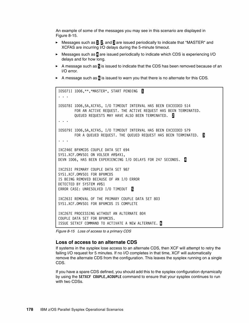
An example of some of the messages you may see in this scenario are displayed in Figure 8-15.
� Messages such as 1, 2, and 3 are issued periodically to indicate that *MASTER* and XCFAS are incurring I/O delays during the 5-minute timeout.
� Messages such as 4 are issued periodically to indicate which CDS is experiencing I/O delays and for how long.
� A message such as 5 is issued to indicate that the CDS has been removed because of an I/O error.
� A message such as 6 is issued to warn you that there is no alternate for this CDS.
Figure 8-15 Loss of access to a primary CDS
Loss of access to an alternate CDSIf systems in the sysplex lose access to an alternate CDS, then XCF will attempt to retry the failing I/O request for 5 minutes. If no I/O completes in that time, XCF will automatically remove the alternate CDS from the configuration. This leaves the sysplex running on a single CDS.
If you have a spare CDS defined, you should add this to the sysplex configuration dynamically by using the SETXCF COUPLE,ACOUPLE command to ensure that your sysplex continues to run with two CDSs.
IOS071I 1D06,**,*MASTER*, START PENDING 1 . . .
IOS078I 1D06,5A,XCFAS, I/O TIMEOUT INTERVAL HAS BEEN EXCEEDED 514 FOR AN ACTIVE REQUEST. THE ACTIVE REQUEST HAS BEEN TERMINATED. QUEUED REQUESTS MAY HAVE ALSO BEEN TERMINATED. 2 . . .
IOS079I 1D06,5A,XCFAS, I/O TIMEOUT INTERVAL HAS BEEN EXCEEDED 579 FOR A QUEUED REQUEST. THE QUEUED REQUEST HAS BEEN TERMINATED. 3 . . .
IXC246E BPXMCDS COUPLE DATA SET 694 SYS1.XCF.OMVS01 ON VOLSER #@$#X1, DEVN 1D06, HAS BEEN EXPERIENCING I/O DELAYS FOR 247 SECONDS. 4
IXC253I PRIMARY COUPLE DATA SET 987 SYS1.XCF.OMVS01 FOR BPXMCDS IS BEING REMOVED BECAUSE OF AN I/O ERROR DETECTED BY SYSTEM #@$1 ERROR CASE: UNRESOLVED I/O TIMEOUT 5
IXC263I REMOVAL OF THE PRIMARY COUPLE DATA SET 803 SYS1.XCF.OMVS01 FOR BPXMCDS IS COMPLETE
IXC267E PROCESSING WITHOUT AN ALTERNATE 804 COUPLE DATA SET FOR BPXMCDS. ISSUE SETXCF COMMAND TO ACTIVATE A NEW ALTERNATE. 6
178 IBM z/OS Parallel Sysplex Operational Scenarios

An example of some of the messages you may see in this scenario are shown in Figure 8-16. These messages are almost identical to the messages you see when you lose access to a primary CDS.
� Messages such as 1, 2, and 3 are issued periodically to indicate that *MASTER* and XCFAS are incurring I/O delays during the 5-minute timeout.
� Messages such as 4 are issued periodically to indicate which CDS is experiencing I/O delays and for how long.
� A message such as 5 is issued to indicate that the CDS has been removed because of an I/O error.
� A message such as 6 is issued to warn you that there is no alternate for this CDS.
Figure 8-16 Loss of access to an alternate CDS
Loss of access to both CDSsThis section examines the impact on the sysplex if a system loses access to both the primary and alternate CDSs.
Sysplex CDSIf a system loses access to both the primary and alternate sysplex CDSs, that system would be unable to update its system status and as a result it would be partitioned out of the sysplex.
IOS071I 1D06,**,*MASTER*, START PENDING 1 . . .
IOS078I 1D06,5A,XCFAS, I/O TIMEOUT INTERVAL HAS BEEN EXCEEDED 514 FOR AN ACTIVE REQUEST. THE ACTIVE REQUEST HAS BEEN TERMINATED. QUEUED REQUESTS MAY HAVE ALSO BEEN TERMINATED. 2 . . .
IOS079I 1D06,5A,XCFAS, I/O TIMEOUT INTERVAL HAS BEEN EXCEEDED 579 FOR A QUEUED REQUEST. THE QUEUED REQUEST HAS BEEN TERMINATED. 3 . . .
IXC246E CFRM COUPLE DATA SET 800 SYS1.XCF.CFRM02 ON VOLSER #@$#X1, DEVN 1D06, HAS BEEN EXPERIENCING I/O DELAYS FOR 249 SECONDS. 4
IXC253I ALTERNATE COUPLE DATA SET 982 SYS1.XCF.CFRM02 FOR CFRM IS BEING REMOVED BECAUSE OF AN I/O ERROR DETECTED BY SYSTEM #@$2 ERROR CASE: UNRESOLVED I/O TIMEOUT 5
IXC263I REMOVAL OF THE ALTERNATE COUPLE DATA SET 778 SYS1.XCF.CFRM02 FOR CFRM IS COMPLETE
IXC267E PROCESSING WITHOUT AN ALTERNATE 868 COUPLE DATA SET FOR CFRM. ISSUE SETXCF COMMAND TO ACTIVATE A NEW ALTERNATE. 6
Chapter 8. Couple Data Set management 179

ARM CDSIf a system loses access to both the primary and alternate ARM CDSs, ARM services on that system are disabled until a primary CDS is assigned.
BPXMCDS CDSIf a system loses access to both the primary and alternate BPXCDS CDSs, that system loses the ability to share UNIX System Services file systems with other systems in the sysplex.
CFRM CDSIf a system loses access to both the primary and alternate CFRM CDSs, that system is placed in a non-restartable disabled wait state X' 0A2' reason code X'9C'.
LOGR CDSIf a system loses access to both the primary and alternate LOGR CDSs, the logger loses connectivity to its inventory data set. The logger address space on that system terminates itself.
SFM CDSIf a system loses access to both the primary and alternate SFM CDSs, SFM is disabled across the entire sysplex.
WLM CDSIf a system loses access to both the primary and alternate WLM CDSs, then Workload Manager continues to run, using the policy information that was in effect at the time of the failure. WLM is described as being in independent mode, operating only on local data, and does not transmit data to other members of the sysplex.
8.5.7 Concurrent CDS and system failure
If a permanent error occurs on a CDS, XCF will attempt to remove the failing CDS from the sysplex configuration. Before the removal can proceed, all systems must agree to remove the CDS. XCF expects all systems to participate in this decision to remove the CDS, and it will wait for every system in the sysplex to respond before completing or rejecting the request.
If a sysplex CDS is being removed and at the same time, one or more systems are unresponsive, then the removal process will hang. This is because of a deadlock on the sysplex CDS between permanent error processing and SFM:
� Permanent error processing prohibits serialized access to the sysplex CDS while it waits until either the unresponsive system is removed from the sysplex or it responds to the request to remove the sysplex CDS.
� SFM cannot remove the unresponsive system until it has updated the recovery record in the sysplex CDS, but it cannot update the sysplex CDS until permanent error processing has finished.
A concurrent failure of one or more CDSs and one or more systems requires a special recovery procedure. When a concurrent failure occurs, if XCF does not receive a response to its CDS removal request from all systems, XCF will issue message IXC256A, as shown in Figure 8-17 on page 181.
180 IBM z/OS Parallel Sysplex Operational Scenarios
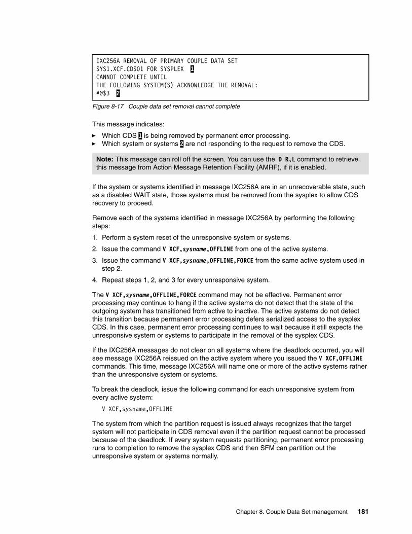
Figure 8-17 Couple data set removal cannot complete
This message indicates:
� Which CDS 1 is being removed by permanent error processing.� Which system or systems 2 are not responding to the request to remove the CDS.
If the system or systems identified in message IXC256A are in an unrecoverable state, such as a disabled WAIT state, those systems must be removed from the sysplex to allow CDS recovery to proceed.
Remove each of the systems identified in message IXC256A by performing the following steps:
1. Perform a system reset of the unresponsive system or systems.
2. Issue the command V XCF,sysname,OFFLINE from one of the active systems.
3. Issue the command V XCF,sysname,OFFLINE,FORCE from the same active system used in step 2.
4. Repeat steps 1, 2, and 3 for every unresponsive system.
The V XCF,sysname,OFFLINE,FORCE command may not be effective. Permanent error processing may continue to hang if the active systems do not detect that the state of the outgoing system has transitioned from active to inactive. The active systems do not detect this transition because permanent error processing defers serialized access to the sysplex CDS. In this case, permanent error processing continues to wait because it still expects the unresponsive system or systems to participate in the removal of the sysplex CDS.
If the IXC256A messages do not clear on all systems where the deadlock occurred, you will see message IXC256A reissued on the active system where you issued the V XCF,OFFLINE commands. This time, message IXC256A will name one or more of the active systems rather than the unresponsive system or systems.
To break the deadlock, issue the following command for each unresponsive system from every active system:
V XCF,sysname,OFFLINE
The system from which the partition request is issued always recognizes that the target system will not participate in CDS removal even if the partition request cannot be processed because of the deadlock. If every system requests partitioning, permanent error processing runs to completion to remove the sysplex CDS and then SFM can partition out the unresponsive system or systems normally.
IXC256A REMOVAL OF PRIMARY COUPLE DATA SETSYS1.XCF.CDS01 FOR SYSPLEX 1 CANNOT COMPLETE UNTILTHE FOLLOWING SYSTEM(S) ACKNOWLEDGE THE REMOVAL:#@$3 2
Note: This message can roll off the screen. You can use the D R,L command to retrieve this message from Action Message Retention Facility (AMRF), if it is enabled.
Chapter 8. Couple Data Set management 181

182 IBM z/OS Parallel Sysplex Operational Scenarios
Chapter 9. XCF management
This chapter describes the Cross-System Coupling Facility (XCF) and operational aspects of XCF including:
� XCF signalling
� XCF groups
� XCF system monitoring
9
© Copyright IBM Corp. 2009. All rights reserved. 183
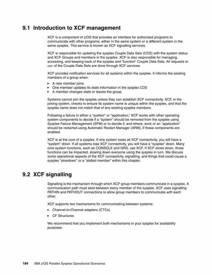
9.1 Introduction to XCF management
XCF is a component of z/OS that provides an interface for authorized programs to communicate with other programs, either in the same system or a different system in the same sysplex. This service is known as XCF signalling services.
XCF is responsible for updating the sysplex Couple Data Sets (CDS) with the system status and XCF Groups and members in the sysplex. XCF is also responsible for managing, accessing, and keeping track of the sysplex and “function” Couple Data Sets. All requests to any of the Couple Data Sets are done through XCF services.
XCF provides notification services for all systems within the sysplex. It informs the existing members of a group when:
� A new member joins� One member updates its state information in the sysplex CDS� A member changes state or leaves the group.
Systems cannot join the sysplex unless they can establish XCF connectivity. XCF, in the joining system, checks to ensure its system name is unique within the sysplex, and that the sysplex name does not match that of any existing sysplex members.
Following a failure in either a “system” or “application,” XCF works with other operating system components to decide if a “system” should be removed from the sysplex using Sysplex Failure Management (SFM) or to decide if, and where, work or an “application” should be restarted using Automatic Restart Manager (ARM), if these components are enabled.
XCF is at the core of a sysplex. If one system loses all XCF connectivity, you will have a “system” down. If all systems lose XCF connectivity, you will have a “sysplex” down. Many core system functions, such as CONSOLE and GRS, use XCF. If XCF slows down, those functions can be impacted, slowing down everyone using the sysplex in turn. We discuss some operational aspects of the XCF connectivity, signalling, and things that could cause a sysplex “slowdown” or a “stalled member” within this chapter.
9.2 XCF signalling
Signalling is the mechanism through which XCF group members communicate in a sysplex. A communication path must exist between every member of the sysplex. XCF uses signalling PATHIN and PATHOUT connections to allow group members to communicate with each other.
XCF supports two mechanisms for communicating between systems:
� Channel-to-Channel adapters (CTCs)
� CF Structures
We recommend that you implement both mechanisms in your sysplex for availability purposes.
184 IBM z/OS Parallel Sysplex Operational Scenarios
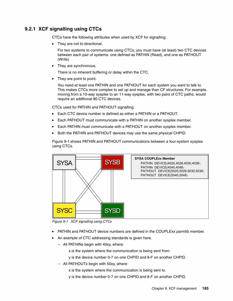
9.2.1 XCF signalling using CTCs
CTCs have the following attributes when used by XCF for signalling:
� They are not bi-directional.
For two systems to communicate using CTCs, you must have (at least) two CTC devices between each pair of systems: one defined as PATHIN (Read), and one as PATHOUT (Write)
� They are synchronous.
There is no inherent buffering or delay within the CTC.
� They are point to point.
You need at least one PATHIN and one PATHOUT for each system you want to talk to. This makes CTCs more complex to set up and manage than CF structures. For example, moving from a 10-way sysplex to an 11-way sysplex, with two pairs of CTC paths, would require an additional 80 CTC devices.
CTCs used for PATHIN and PATHOUT signalling:
� Each CTC device number is defined as either a PATHIN or a PATHOUT.
� Each PATHOUT must communicate with a PATHIN on another sysplex member.
� Each PATHIN must communicate with a PATHOUT on another sysplex member.
� Both the PATHIN and PATHOUT devices may use the same physical CHPID.
Figure 9-1 shows PATHIN and PATHOUT communications between a four-system sysplex using CTCs.
Figure 9-1 XCF signalling using CTCs
� PATHIN and PATHOUT device numbers are defined in the COUPLExx parmlib member.
� An example of CTC addressing standards is given here.
– All PATHINs begin with 40xy, where:
x is the system where the communication is being sent from.
y is the device number 0-7 on one CHPID and 8-F on another CHPID.
– All PATHOUTs begin with 50xy, where:
x is the system where the communication is being sent to.
y is the device number 0-7 on one CHPID and 8-F on another CHPID.
SYSA
SYSC
SYSBSYSB
SYSDSYSD
SYSA COUPLExx Member PATHIN DEVICE(4020,4028,4030,4038)
PATHOUT DEVICE(5020,5028,5030,5038) PATHIN DEVICE(4040,4048)
PATHOUT DEVICE(5040,5048)
Chapter 9. XCF management 185

9.2.2 XCF signalling using structures
XCF can use the list structure capabilities of the Coupling Facility (CF) to provide signalling connectivity between sysplex members.
Structures have the following attributes when used by XCF:
� They are bidirectional (from a definition perspective).
Each XCF structure should be defined as both PATHIN and PATHOUT to every system.
� They are asynchronous.
A message is sent to CF. Then CF notifies the target system. Finally, the target system collects the message.
� They are multi-connected.
A CF structure would be used as both PATHIN and PATHOUT by every system. This makes them much easier to define and manage than CTCs.
Figure 9-2 shows PATHIN and PATHOUT communications between a four-system sysplex using structures.
Figure 9-2 XCF signalling using structures
� The COUPLExx parmlib member defines the PATHOUT and PATHIN with a structure name of IXC_xxxxx (the structure name must begin with IXC).
� Multiple signalling structures can be specified in the COUPLExx member.
� The structure name must be in the active CFRM policy.
� During IPL, z/OS will establish a signalling path to every other image using the CF.
9.2.3 Displaying XCF PATHIN
The D XCF,PATHIN (or PI) command, as shown in Figure 9-3 on page 187, can be issued to determine the current status of the structures and CTCs PATHIN and PATHOUT signalling paths.
SYSA SYSBSYSB
SYSC SYSDSYSD
CF
PATHIN STRNAME(IXC_DEFAULT_1) PATHOUT STRNAME(IXC_DEFAULT_1)
SYSD COUPLExx Member
PATHIN STRNAME(IXC_DEFAULT_1) PATHOUT STRNAME(IXC_DEFAULT_1)
SYSA COUPLExx Member
PATHIN STRNAME(IXC_DEFAULT_1) PATHOUT STRNAME(IXC_DEFAULT_1)
SYSB COUPLExx Member
PATHIN STRNAME(IXC_DEFAULT_1) PATHOUT STRNAME(IXC_DEFAULT_1)
SYSC COUPLExx Member
186 IBM z/OS Parallel Sysplex Operational Scenarios
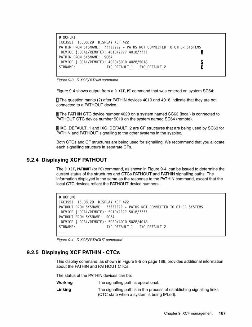
Figure 9-3 D XCF,PATHIN command
Figure 9-4 shows output from a D XCF,PI command that was entered on system SC64:
1 The question marks (?) after PATHIN devices 4010 and 4018 indicate that they are not connected to a PATHOUT device.
2 The PATHIN CTC device number 4020 on a system named SC63 (local) is connected to PATHOUT CTC device number 5010 on the system named SC64 (remote).
3 IXC_DEFAULT_1 and IXC_DEFAULT_2 are CF structures that are being used by SC63 for PATHIN and PATHOUT signalling to the other systems in the sysplex.
Both CTCs and CF structures are being used for signalling. We recommend that you allocate each signalling structure in separate CFs.
9.2.4 Displaying XCF PATHOUT
The D XCF,PATHOUT (or PO) command, as shown in Figure 9-4, can be issued to determine the current status of the structures and CTCs PATHOUT and PATHIN signalling paths. The information displayed is the same as the response to the PATHIN command, except that the local CTC devices reflect the PATHOUT device numbers.
Figure 9-4 D XCF,PATHOUT command
9.2.5 Displaying XCF PATHIN - CTCs
This display command, as shown in Figure 9-5 on page 188, provides additional information about the PATHIN and PATHOUT CTCs.
The status of the PATHIN devices can be:
Working The signalling path is operational.
Linking The signalling path is in the process of establishing signalling links (CTC state when a system is being IPLed).
D XCF,PIIXC355I 15.08.29 DISPLAY XCF 422 PATHIN FROM SYSNAME: ???????? - PATHS NOT CONNECTED TO OTHER SYSTEMS DEVICE (LOCAL/REMOTE): 4010/???? 4018/???? 1 PATHIN FROM SYSNAME: SC64 DEVICE (LOCAL/REMOTE): 4020/5010 4028/5018 2 STRNAME: IXC_DEFAULT_1 IXC_DEFAULT_2 3 ...
D XCF,POIXC355I 15.08.29 DISPLAY XCF 422 PATHOUT FROM SYSNAME: ???????? - PATHS NOT CONNECTED TO OTHER SYSTEMS DEVICE (LOCAL/REMOTE): 5010/???? 5018/???? PATHOUT FROM SYSNAME: SC64 DEVICE (LOCAL/REMOTE): 5020/4010 5028/4018 STRNAME: IXC_DEFAULT_1 IXC_DEFAULT_2 ...
Chapter 9. XCF management 187
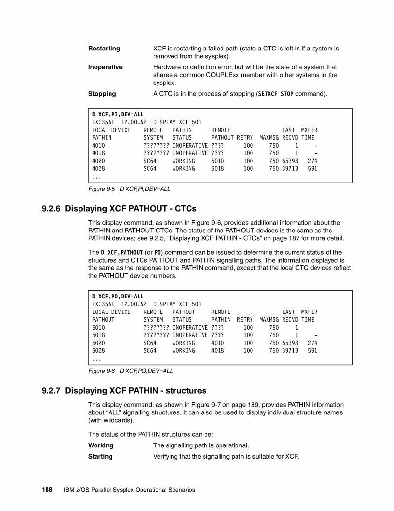
Restarting XCF is restarting a failed path (state a CTC is left in if a system is removed from the sysplex).
Inoperative Hardware or definition error, but will be the state of a system that shares a common COUPLExx member with other systems in the sysplex.
Stopping A CTC is in the process of stopping (SETXCF STOP command).
Figure 9-5 D XCF,PI,DEV=ALL
9.2.6 Displaying XCF PATHOUT - CTCs
This display command, as shown in Figure 9-6, provides additional information about the PATHIN and PATHOUT CTCs. The status of the PATHOUT devices is the same as the PATHIN devices; see 9.2.5, “Displaying XCF PATHIN - CTCs” on page 187 for more detail.
The D XCF,PATHOUT (or PO) command can be issued to determine the current status of the structures and CTCs PATHOUT and PATHIN signalling paths. The information displayed is the same as the response to the PATHIN command, except that the local CTC devices reflect the PATHOUT device numbers.
Figure 9-6 D XCF,PO,DEV=ALL
9.2.7 Displaying XCF PATHIN - structures
This display command, as shown in Figure 9-7 on page 189, provides PATHIN information about “ALL” signalling structures. It can also be used to display individual structure names (with wildcards).
The status of the PATHIN structures can be:
Working The signalling path is operational.
Starting Verifying that the signalling path is suitable for XCF.
D XCF,PI,DEV=ALLIXC356I 12.00.52 DISPLAY XCF 501 LOCAL DEVICE REMOTE PATHIN REMOTE LAST MXFER PATHIN SYSTEM STATUS PATHOUT RETRY MAXMSG RECVD TIME 4010 ???????? INOPERATIVE ???? 100 750 1 - 4018 ???????? INOPERATIVE ???? 100 750 1 - 4020 SC64 WORKING 5010 100 750 65393 274 4028 SC64 WORKING 5018 100 750 39713 591 ...
D XCF,PO,DEV=ALLIXC356I 12.00.52 DISPLAY XCF 501 LOCAL DEVICE REMOTE PATHOUT REMOTE LAST MXFER PATHOUT SYSTEM STATUS PATHIN RETRY MAXMSG RECVD TIME 5010 ???????? INOPERATIVE ???? 100 750 1 - 5018 ???????? INOPERATIVE ???? 100 750 1 - 5020 SC64 WORKING 4010 100 750 65393 274 5028 SC64 WORKING 4018 100 750 39713 591 ...
188 IBM z/OS Parallel Sysplex Operational Scenarios
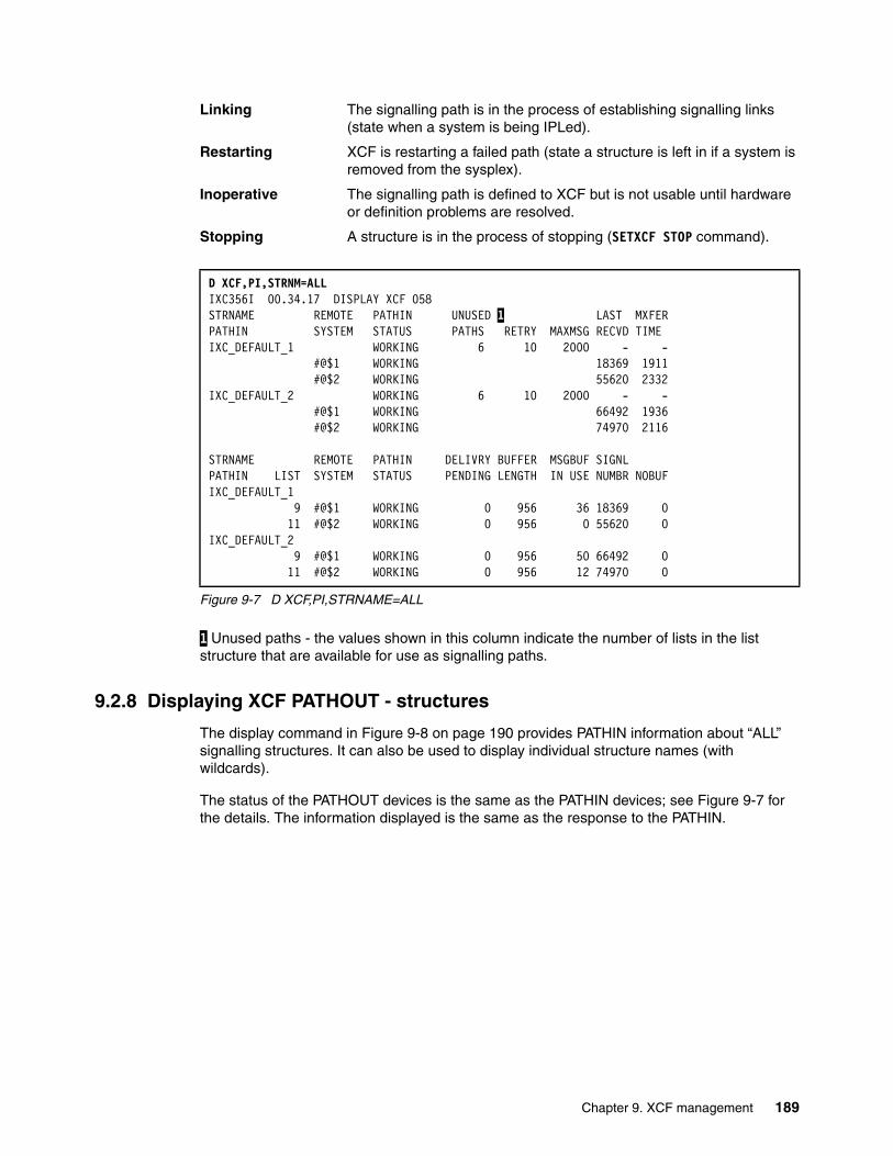
Linking The signalling path is in the process of establishing signalling links (state when a system is being IPLed).
Restarting XCF is restarting a failed path (state a structure is left in if a system is removed from the sysplex).
Inoperative The signalling path is defined to XCF but is not usable until hardware or definition problems are resolved.
Stopping A structure is in the process of stopping (SETXCF STOP command).
Figure 9-7 D XCF,PI,STRNAME=ALL
1 Unused paths - the values shown in this column indicate the number of lists in the list structure that are available for use as signalling paths.
9.2.8 Displaying XCF PATHOUT - structures
The display command in Figure 9-8 on page 190 provides PATHIN information about “ALL” signalling structures. It can also be used to display individual structure names (with wildcards).
The status of the PATHOUT devices is the same as the PATHIN devices; see Figure 9-7 for the details. The information displayed is the same as the response to the PATHIN.
D XCF,PI,STRNM=ALLIXC356I 00.34.17 DISPLAY XCF 058 STRNAME REMOTE PATHIN UNUSED 1 LAST MXFERPATHIN SYSTEM STATUS PATHS RETRY MAXMSG RECVD TIME IXC_DEFAULT_1 WORKING 6 10 2000 - - #@$1 WORKING 18369 1911 #@$2 WORKING 55620 2332IXC_DEFAULT_2 WORKING 6 10 2000 - - #@$1 WORKING 66492 1936 #@$2 WORKING 74970 2116 STRNAME REMOTE PATHIN DELIVRY BUFFER MSGBUF SIGNL PATHIN LIST SYSTEM STATUS PENDING LENGTH IN USE NUMBR NOBUFIXC_DEFAULT_1 9 #@$1 WORKING 0 956 36 18369 0 11 #@$2 WORKING 0 956 0 55620 0IXC_DEFAULT_2 9 #@$1 WORKING 0 956 50 66492 0 11 #@$2 WORKING 0 956 12 74970 0
Chapter 9. XCF management 189
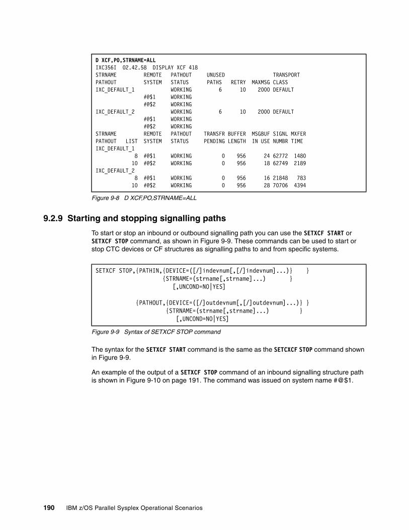
Figure 9-8 D XCF,PO,STRNAME=ALL
9.2.9 Starting and stopping signalling paths
To start or stop an inbound or outbound signalling path you can use the SETXCF START or SETXCF STOP command, as shown in Figure 9-9. These commands can be used to start or stop CTC devices or CF structures as signalling paths to and from specific systems.
Figure 9-9 Syntax of SETXCF STOP command
The syntax for the SETXCF START command is the same as the SETCXCF STOP command shown in Figure 9-9.
An example of the output of a SETXCF STOP command of an inbound signalling structure path is shown in Figure 9-10 on page 191. The command was issued on system name #@$1.
D XCF,PO,STRNAME=ALLIXC356I 02.42.58 DISPLAY XCF 418 STRNAME REMOTE PATHOUT UNUSED TRANSPORT PATHOUT SYSTEM STATUS PATHS RETRY MAXMSG CLASS IXC_DEFAULT_1 WORKING 6 10 2000 DEFAULT #@$1 WORKING #@$2 WORKING IXC_DEFAULT_2 WORKING 6 10 2000 DEFAULT #@$1 WORKING #@$2 WORKING STRNAME REMOTE PATHOUT TRANSFR BUFFER MSGBUF SIGNL MXFERPATHOUT LIST SYSTEM STATUS PENDING LENGTH IN USE NUMBR TIME IXC_DEFAULT_1 8 #@$1 WORKING 0 956 24 62772 1480 10 #@$2 WORKING 0 956 18 62749 2189IXC_DEFAULT_2 8 #@$1 WORKING 0 956 16 21848 783 10 #@$2 WORKING 0 956 28 70706 4394
SETXCF STOP,{PATHIN,{DEVICE=([/]indevnum[,[/]indevnum]...)} } {STRNAME=(strname[,strname]...) } [,UNCOND=NO|YES] {PATHOUT,{DEVICE=([/]outdevnum[,[/]outdevnum]...)} } {STRNAME=(strname[,strname]...) } [,UNCOND=NO|YES]
190 IBM z/OS Parallel Sysplex Operational Scenarios
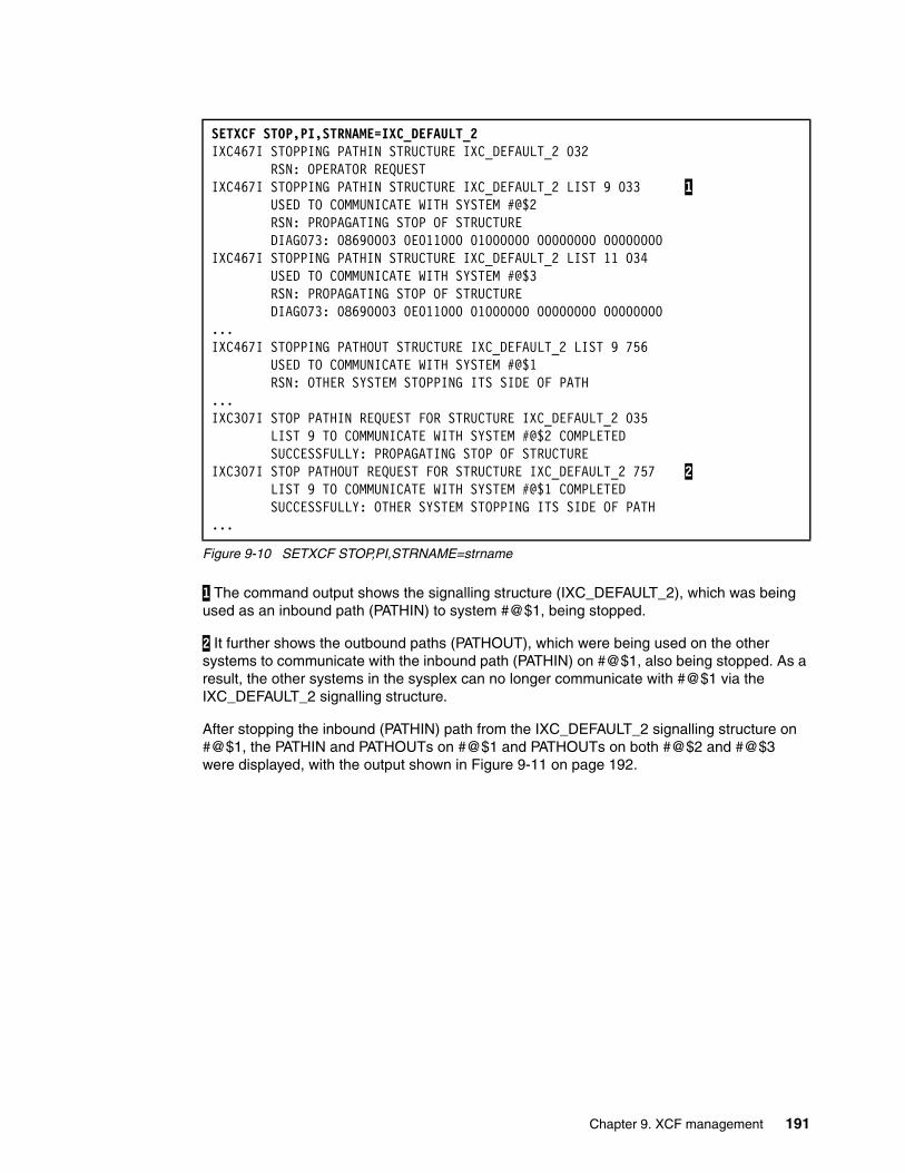
Figure 9-10 SETXCF STOP,PI,STRNAME=strname
1 The command output shows the signalling structure (IXC_DEFAULT_2), which was being used as an inbound path (PATHIN) to system #@$1, being stopped.
2 It further shows the outbound paths (PATHOUT), which were being used on the other systems to communicate with the inbound path (PATHIN) on #@$1, also being stopped. As a result, the other systems in the sysplex can no longer communicate with #@$1 via the IXC_DEFAULT_2 signalling structure.
After stopping the inbound (PATHIN) path from the IXC_DEFAULT_2 signalling structure on #@$1, the PATHIN and PATHOUTs on #@$1 and PATHOUTs on both #@$2 and #@$3 were displayed, with the output shown in Figure 9-11 on page 192.
SETXCF STOP,PI,STRNAME=IXC_DEFAULT_2 IXC467I STOPPING PATHIN STRUCTURE IXC_DEFAULT_2 032 RSN: OPERATOR REQUEST IXC467I STOPPING PATHIN STRUCTURE IXC_DEFAULT_2 LIST 9 033 1 USED TO COMMUNICATE WITH SYSTEM #@$2 RSN: PROPAGATING STOP OF STRUCTURE DIAG073: 08690003 0E011000 01000000 00000000 00000000IXC467I STOPPING PATHIN STRUCTURE IXC_DEFAULT_2 LIST 11 034 USED TO COMMUNICATE WITH SYSTEM #@$3 RSN: PROPAGATING STOP OF STRUCTURE DIAG073: 08690003 0E011000 01000000 00000000 00000000...IXC467I STOPPING PATHOUT STRUCTURE IXC_DEFAULT_2 LIST 9 756 USED TO COMMUNICATE WITH SYSTEM #@$1 RSN: OTHER SYSTEM STOPPING ITS SIDE OF PATH ...IXC307I STOP PATHIN REQUEST FOR STRUCTURE IXC_DEFAULT_2 035 LIST 9 TO COMMUNICATE WITH SYSTEM #@$2 COMPLETED SUCCESSFULLY: PROPAGATING STOP OF STRUCTURE IXC307I STOP PATHOUT REQUEST FOR STRUCTURE IXC_DEFAULT_2 757 2 LIST 9 TO COMMUNICATE WITH SYSTEM #@$1 COMPLETED SUCCESSFULLY: OTHER SYSTEM STOPPING ITS SIDE OF PATH ...
Chapter 9. XCF management 191
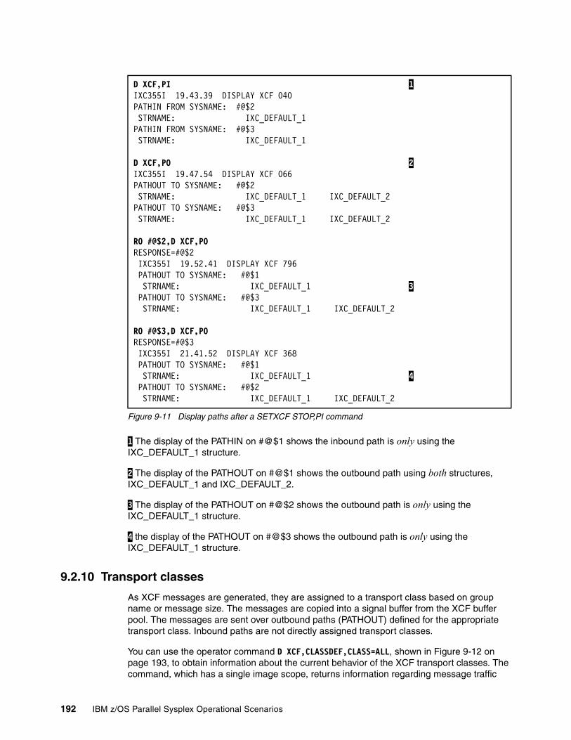
Figure 9-11 Display paths after a SETXCF STOP,PI command
1 The display of the PATHIN on #@$1 shows the inbound path is only using the IXC_DEFAULT_1 structure.
2 The display of the PATHOUT on #@$1 shows the outbound path using both structures, IXC_DEFAULT_1 and IXC_DEFAULT_2.
3 The display of the PATHOUT on #@$2 shows the outbound path is only using the IXC_DEFAULT_1 structure.
4 the display of the PATHOUT on #@$3 shows the outbound path is only using the IXC_DEFAULT_1 structure.
9.2.10 Transport classes
As XCF messages are generated, they are assigned to a transport class based on group name or message size. The messages are copied into a signal buffer from the XCF buffer pool. The messages are sent over outbound paths (PATHOUT) defined for the appropriate transport class. Inbound paths are not directly assigned transport classes.
You can use the operator command D XCF,CLASSDEF,CLASS=ALL, shown in Figure 9-12 on page 193, to obtain information about the current behavior of the XCF transport classes. The command, which has a single image scope, returns information regarding message traffic
D XCF,PI 1 IXC355I 19.43.39 DISPLAY XCF 040 PATHIN FROM SYSNAME: #@$2 STRNAME: IXC_DEFAULT_1 PATHIN FROM SYSNAME: #@$3 STRNAME: IXC_DEFAULT_1
D XCF,PO 2 IXC355I 19.47.54 DISPLAY XCF 066 PATHOUT TO SYSNAME: #@$2 STRNAME: IXC_DEFAULT_1 IXC_DEFAULT_2 PATHOUT TO SYSNAME: #@$3 STRNAME: IXC_DEFAULT_1 IXC_DEFAULT_2
RO #@$2,D XCF,PORESPONSE=#@$2 IXC355I 19.52.41 DISPLAY XCF 796 PATHOUT TO SYSNAME: #@$1 STRNAME: IXC_DEFAULT_1 3 PATHOUT TO SYSNAME: #@$3 STRNAME: IXC_DEFAULT_1 IXC_DEFAULT_2
RO #@$3,D XCF,PORESPONSE=#@$3 IXC355I 21.41.52 DISPLAY XCF 368 PATHOUT TO SYSNAME: #@$1 STRNAME: IXC_DEFAULT_1 4 PATHOUT TO SYSNAME: #@$2 STRNAME: IXC_DEFAULT_1 IXC_DEFAULT_2
192 IBM z/OS Parallel Sysplex Operational Scenarios
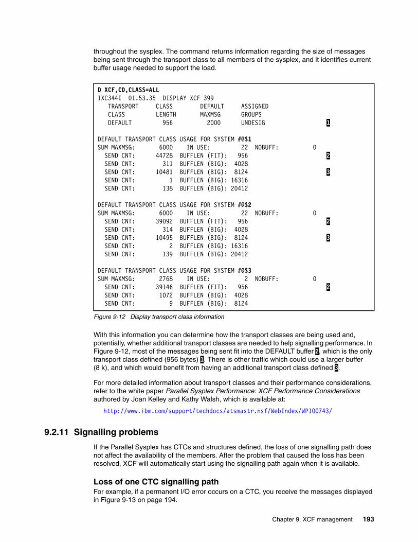
throughout the sysplex. The command returns information regarding the size of messages being sent through the transport class to all members of the sysplex, and it identifies current buffer usage needed to support the load.
Figure 9-12 Display transport class information
With this information you can determine how the transport classes are being used and, potentially, whether additional transport classes are needed to help signalling performance. In Figure 9-12, most of the messages being sent fit into the DEFAULT buffer 2, which is the only transport class defined (956 bytes) 1. There is other traffic which could use a larger buffer (8 k), and which would benefit from having an additional transport class defined 3.
For more detailed information about transport classes and their performance considerations, refer to the white paper Parallel Sysplex Performance: XCF Performance Considerations authored by Joan Kelley and Kathy Walsh, which is available at:
http://www.ibm.com/support/techdocs/atsmastr.nsf/WebIndex/WP100743/
9.2.11 Signalling problems
If the Parallel Sysplex has CTCs and structures defined, the loss of one signalling path does not affect the availability of the members. After the problem that caused the loss has been resolved, XCF will automatically start using the signalling path again when it is available.
Loss of one CTC signalling pathFor example, if a permanent I/O error occurs on a CTC, you receive the messages displayed in Figure 9-13 on page 194.
D XCF,CD,CLASS=ALLIXC344I 01.53.35 DISPLAY XCF 399 TRANSPORT CLASS DEFAULT ASSIGNED CLASS LENGTH MAXMSG GROUPS DEFAULT 956 2000 UNDESIG 1 DEFAULT TRANSPORT CLASS USAGE FOR SYSTEM #@$1 SUM MAXMSG: 6000 IN USE: 22 NOBUFF: 0 SEND CNT: 44728 BUFFLEN (FIT): 956 2 SEND CNT: 311 BUFFLEN (BIG): 4028 SEND CNT: 10481 BUFFLEN (BIG): 8124 3 SEND CNT: 1 BUFFLEN (BIG): 16316 SEND CNT: 138 BUFFLEN (BIG): 20412
DEFAULT TRANSPORT CLASS USAGE FOR SYSTEM #@$2 SUM MAXMSG: 6000 IN USE: 22 NOBUFF: 0 SEND CNT: 39092 BUFFLEN (FIT): 956 2 SEND CNT: 314 BUFFLEN (BIG): 4028 SEND CNT: 10495 BUFFLEN (BIG): 8124 3 SEND CNT: 2 BUFFLEN (BIG): 16316 SEND CNT: 139 BUFFLEN (BIG): 20412
DEFAULT TRANSPORT CLASS USAGE FOR SYSTEM #@$3 SUM MAXMSG: 2768 IN USE: 2 NOBUFF: 0 SEND CNT: 39146 BUFFLEN (FIT): 956 2 SEND CNT: 1072 BUFFLEN (BIG): 4028 SEND CNT: 9 BUFFLEN (BIG): 8124
Chapter 9. XCF management 193

Figure 9-13 Loss of a CTC signalling path
Problem diagnosis and recovery should be performed on the failing device. After the problem has been resolved and the device has been successfully varied online, XCF will start using it again, as shown in Figure 9-14.
Figure 9-14 CTC signalling path recovery
For examples of signalling problems during IPLs, refer to 3.6.6, “Unable to establish XCF connectivity” on page 56.
9.3 XCF groups
Before an application can use XCF signalling services, it must join the same XCF group that its peers are in, using an agreed group name. To obtain a list of all groups in the sysplex, as well as the number of members in each group, use the D XCF,GROUP command as shown in Figure 9-15.
Figure 9-15 XCF group list
Group names are important because they are one way of segregating XCF message traffic. Table 9-1 on page 195 lists common IBM XCF groups. Other vendor products may have other XCF groups, which are not listed in the table.
IOS102I DEVICE 4020 BOXED, PERMANENT I/O ERROR IEE793I 4020 PENDING OFFLINE AND BOXED IXC467I RESTARTING PATHIN DEVICE 4020 506 USED TO COMMUNICATE WITH SYSTEM SC64 RSN: I/O ERROR WHILE WORKING
IXC467I STOPPING PATHIN DEVICE 4020 508 USED TO COMMUNICATE WITH SYSTEM SC64 RSN: HALT I/O FAILED DIAG073:08220003 0000000C 0000000C 00000001 00000000 IXC307I STOP PATHIN REQUEST FOR DEVICE 4020 COMPLETED 509 SUCCESSFULLY: HALT I/O FAILED
V 4020,ONLINE,UNCONDIEE302I 4020 ONLINEIXC306I START PATHIN REQUEST FOR DEVICE 4020 COMPLETED 339SUCCESSFULLY: DEVICE CAME ONLINEIXC466I INBOUND SIGNAL CONNECTIVITY ESTABLISHED WITH SYSTEM SC64 340 VIA DEVICE 4020 WHICH IS CONNECTED TO DEVICE 5010
D XCF,GIXC331I 01.56.43 DISPLAY XCF 138 GROUPS(SIZE): ATRRRS(3) COFVLFNO(3) CSQGPSMG(3)
EZBTCPCS(3) IDAVQUI0(3) IGWXSGIS(6) ...
SYSMCS2(8) SYSRMF(3) SYSTTRC(3) SYSWLM(3) SYSXCF(2) XCFJES2A(3)
194 IBM z/OS Parallel Sysplex Operational Scenarios
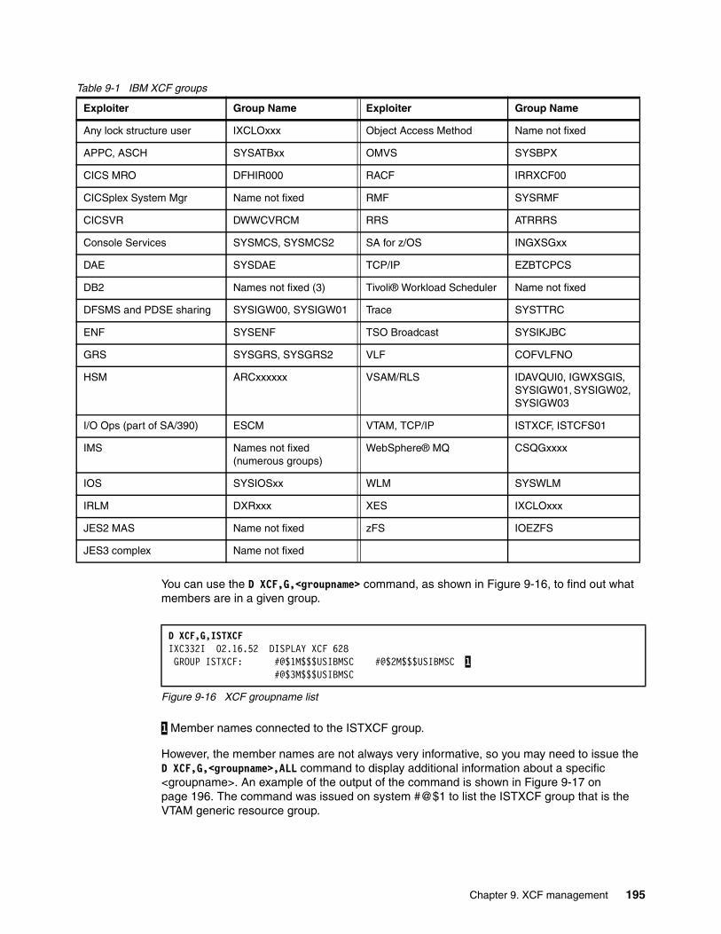
Table 9-1 IBM XCF groups
You can use the D XCF,G,<groupname> command, as shown in Figure 9-16, to find out what members are in a given group.
Figure 9-16 XCF groupname list
1 Member names connected to the ISTXCF group.
However, the member names are not always very informative, so you may need to issue the D XCF,G,<groupname>,ALL command to display additional information about a specific <groupname>. An example of the output of the command is shown in Figure 9-17 on page 196. The command was issued on system #@$1 to list the ISTXCF group that is the VTAM generic resource group.
Exploiter Group Name Exploiter Group Name
Any lock structure user IXCLOxxx Object Access Method Name not fixed
APPC, ASCH SYSATBxx OMVS SYSBPX
CICS MRO DFHIR000 RACF IRRXCF00
CICSplex System Mgr Name not fixed RMF SYSRMF
CICSVR DWWCVRCM RRS ATRRRS
Console Services SYSMCS, SYSMCS2 SA for z/OS INGXSGxx
DAE SYSDAE TCP/IP EZBTCPCS
DB2 Names not fixed (3) Tivoli® Workload Scheduler Name not fixed
DFSMS and PDSE sharing SYSIGW00, SYSIGW01 Trace SYSTTRC
ENF SYSENF TSO Broadcast SYSIKJBC
GRS SYSGRS, SYSGRS2 VLF COFVLFNO
HSM ARCxxxxxx VSAM/RLS IDAVQUI0, IGWXSGIS, SYSIGW01, SYSIGW02, SYSIGW03
I/O Ops (part of SA/390) ESCM VTAM, TCP/IP ISTXCF, ISTCFS01
IMS Names not fixed (numerous groups)
WebSphere® MQ CSQGxxxx
IOS SYSIOSxx WLM SYSWLM
IRLM DXRxxx XES IXCLOxxx
JES2 MAS Name not fixed zFS IOEZFS
JES3 complex Name not fixed
D XCF,G,ISTXCF IXC332I 02.16.52 DISPLAY XCF 628 GROUP ISTXCF: #@$1M$$$USIBMSC #@$2M$$$USIBMSC 1 #@$3M$$$USIBMSC
Chapter 9. XCF management 195
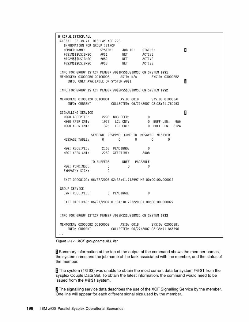
Figure 9-17 XCF groupname ALL list
1 Summary information at the top of the output of the command shows the member names, the system name and the job name of the task associated with the member, and the status of the member.
2 The system (#@$3) was unable to obtain the most current data for system #@$1 from the sysplex Couple Data Set. To obtain the latest information, the command would need to be issued from the #@$1 system.
3 The signalling service data describes the use of the XCF Signalling Service by the member. One line will appear for each different signal size used by the member.
D XCF,G,ISTXCF,ALL IXC333I 02.38.41 DISPLAY XCF 723 INFORMATION FOR GROUP ISTXCF MEMBER NAME: SYSTEM: JOB ID: STATUS: 1 #@$1M$$$USIBMSC #@$1 NET ACTIVE #@$2M$$$USIBMSC #@$2 NET ACTIVE #@$3M$$$USIBMSC #@$3 NET ACTIVE INFO FOR GROUP ISTXCF MEMBER #@$1M$$$USIBMSC ON SYSTEM #@$1 MEMTOKEN: 030000B6 001C0003 ASID: N/A SYSID: 030002B2 INFO: ONLY AVAILABLE ON SYSTEM #@$1 2
INFO FOR GROUP ISTXCF MEMBER #@$2M$$$USIBMSC ON SYSTEM #@$2 MEMTOKEN: 01000120 001C0001 ASID: 001B SYSID: 010002AF INFO: CURRENT COLLECTED: 06/27/2007 02:38:41.760953 SIGNALLING SERVICE 3 MSGO ACCEPTED: 2298 NOBUFFER: 0 MSGO XFER CNT: 1973 LCL CNT: 0 BUFF LEN: 956 MSGO XFER CNT: 325 LCL CNT: 0 BUFF LEN: 8124 SENDPND RESPPND COMPLTD MOSAVED MISAVED MESSAGE TABLE: 0 0 0 0 0 MSGI RECEIVED: 2153 PENDINGQ: 0 MSGI XFER CNT: 2259 XFERTIME: 2408
IO BUFFERS DREF PAGEABLE MSGI PENDINGQ: 0 0 0 SYMPATHY SICK: 0 EXIT 04C08100: 06/27/2007 02:38:41.718997 ME 00:00:00.000017 GROUP SERVICE EVNT RECEIVED: 6 PENDINGQ: 0 EXIT 01E51CA0: 06/27/2007 01:31:30.723220 01 00:00:00.000027 INFO FOR GROUP ISTXCF MEMBER #@$3M$$$USIBMSC ON SYSTEM #@$3 MEMTOKEN: 020000B2 001C0002 ASID: 001B SYSID: 020002B1 INFO: CURRENT COLLECTED: 06/27/2007 02:38:41.866796...
196 IBM z/OS Parallel Sysplex Operational Scenarios
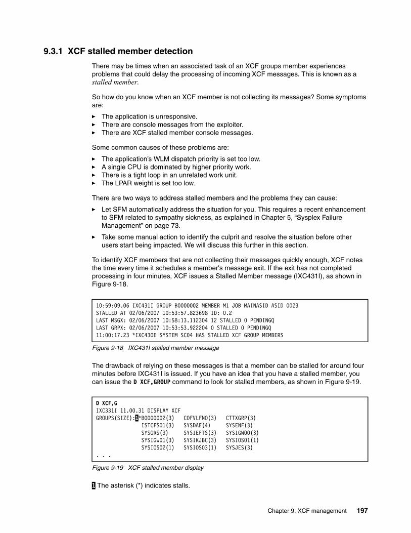
9.3.1 XCF stalled member detection
There may be times when an associated task of an XCF groups member experiences problems that could delay the processing of incoming XCF messages. This is known as a stalled member.
So how do you know when an XCF member is not collecting its messages? Some symptoms are:
� The application is unresponsive.� There are console messages from the exploiter.� There are XCF stalled member console messages.
Some common causes of these problems are:
� The application’s WLM dispatch priority is set too low.� A single CPU is dominated by higher priority work.� There is a tight loop in an unrelated work unit.� The LPAR weight is set too low.
There are two ways to address stalled members and the problems they can cause:
� Let SFM automatically address the situation for you. This requires a recent enhancement to SFM related to sympathy sickness, as explained in Chapter 5, “Sysplex Failure Management” on page 73.
� Take some manual action to identify the culprit and resolve the situation before other users start being impacted. We will discuss this further in this section.
To identify XCF members that are not collecting their messages quickly enough, XCF notes the time every time it schedules a member's message exit. If the exit has not completed processing in four minutes, XCF issues a Stalled Member message (IXC431I), as shown in Figure 9-18.
Figure 9-18 IXC431I stalled member message
The drawback of relying on these messages is that a member can be stalled for around four minutes before IXC431I is issued. If you have an idea that you have a stalled member, you can issue the D XCF,GROUP command to look for stalled members, as shown in Figure 9-19.
Figure 9-19 XCF stalled member display
1 The asterisk (*) indicates stalls.
10:59:09.06 IXC431I GROUP B0000002 MEMBER M1 JOB MAINASID ASID 0023STALLED AT 02/06/2007 10:53:57.823698 ID: 0.2LAST MSGX: 02/06/2007 10:58:13.112304 12 STALLED 0 PENDINGQLAST GRPX: 02/06/2007 10:53:53.922204 0 STALLED 0 PENDINGQ11:00:17.23 *IXC430E SYSTEM SC04 HAS STALLED XCF GROUP MEMBERS
D XCF,GIXC331I 11.00.31 DISPLAY XCFGROUPS(SIZE):1*B0000002(3) COFVLFNO(3) CTTXGRP(3)
ISTCFS01(3) SYSDAE(4) SYSENF(3)SYSGRS(3) SYSIEFTS(3) SYSIGW00(3)SYSIGW01(3) SYSIKJBC(3) SYSIOS01(1)SYSIOS02(1) SYSIOS03(1) SYSJES(3)
. . .
Chapter 9. XCF management 197
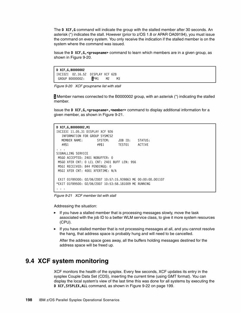
The D XCF,G command will indicate the group with the stalled member after 30 seconds. An asterisk (*) indicates the stall. However (prior to z/OS 1.8 or APAR OA09194), you must issue the command on every system. You only receive the indication if the stalled member is on the system where the command was issued.
Issue the D XCF,G,<groupname> command to learn which members are in a given group, as shown in Figure 9-20.
Figure 9-20 XCF groupname list with stall
1 Member names connected to the B0000002 group, with an asterisk (*) indicating the stalled member.
Issue the D XCF,G,<groupname>,<member> command to display additional information for a given member, as shown in Figure 9-21.
Figure 9-21 XCF member list with stall
Addressing the situation:
� If you have a stalled member that is processing messages slowly, move the task associated with the job ID to a better WLM service class, to give it more system resources (CPU).
� If you have stalled member that is not processing messages at all, and you cannot resolve the hang, that address space is probably hung and will need to be cancelled.
After the address space goes away, all the buffers holding messages destined for the address space will be freed up.
9.4 XCF system monitoring
XCF monitors the health of the sysplex. Every few seconds, XCF updates its entry in the sysplex Couple Data Set (CDS), inserting the current time (using GMT format). You can display the local system's view of the last time this was done for all systems by executing the D XCF,SYSPLEX,ALL command, as shown in Figure 9-22 on page 199.
D XCF,G,B0000002 IXC332I 02.16.52 DISPLAY XCF 628 GROUP B0000002: 1*M1 M2 M3
D XCF,G,B0000002,M1IXC333I 11.05.31 DISPLAY XCF 926 INFORMATION FOR GROUP SYSMCS2 MEMBER NAME: SYSTEM: JOB ID: STATUS: #@$1 #@$1 TEST01 ACTIVE . . .SIGNALLING SERVICEMSGO ACCEPTED: 2401 NOBUFFER: 0MSGO XFER CNT: 0 LCL CNT: 2401 BUFF LEN: 956MSGI RECEIVED: 844 PENDINGQ: 0MSGI XFER CNT: 4001 XFERTIME: N/A
EXIT 01FB9300: 02/06/2007 10:57:15.939863 ME 00:00:00.001107*EXIT 01FB9500: 02/06/2007 10:53:58.181009 ME RUNNING. . .
198 IBM z/OS Parallel Sysplex Operational Scenarios

Figure 9-22 XCF display of active systems
XCF also checks the time stamp for all the other ACTIVE members. If any system’s time stamp is older than the current time, minus that system’s INTERVAL value from the COUPLExx parmlib member, then XCF suspects that the system may be dead and flags the status of the system with a non-active status, as shown in Figure 9-23.
Figure 9-23 XCF display of active systems with a failed system
1 MONITOR-DETECTED STOP means the system has not updated its status on the CDS within the time interval specified on that system's COUPLExx parmlib member. This can mean that:
� The system is going through reconfiguration.� A spin loop is occurring.� The operator pressed stop.� The system is in a restartable wait state.� The system lost access to the couple data set.
The next step depends on whether there is an active SFM policy:
� If there is an active SFM policy in your sysplex, XCF checks to see if the “dead” system is issuing any XCF signals. If it is still issuing signals, message IXC426D is issued. If it is not, issuing signals and you specify ISOLATETIME(0), SFM will automatically partition the system from the sysplex.
� If there is no active SFM policy in your sysplex, message IXC402D is issued, asking you to remove the sick system, or wait sssss seconds, as shown in Figure 9-24, and check again for the heartbeat (checking for XCF signals is not performed in this case).
Figure 9-24 IXC402D message
D XCF,S,ALL IXC335I 21.03.32 DISPLAY XCF 769 SYSTEM TYPE SERIAL LPAR STATUS TIME SYSTEM STATUS #@$2 2084 6A3A N/A 06/27/2007 21:03:28 ACTIVE TM=SIMETR#@$3 2084 6A3A N/A 06/27/2007 21:03:32 ACTIVE TM=SIMETR#@$1 2084 6A3A N/A 06/27/2007 21:03:29 ACTIVE TM=SIMETR
D XCF,S,ALL IXC335I 21.19.46 DISPLAY XCF 870 SYSTEM TYPE SERIAL LPAR STATUS TIME SYSTEM STATUS #@$2 2084 6A3A N/A 06/27/2007 21:15:08 MONITOR-DETECTED STOP 1#@$3 2084 6A3A N/A 06/27/2007 21:19:45 ACTIVE TM=SIMETR#@$1 2084 6A3A N/A 06/27/2007 21:19:44 ACTIVE TM=SIMETR
*026 IXC402D #@$2 LAST OPERATIVE AT 21:15:08. REPLY DOWN AFTER SYSTEM RESET, OR INTERVAL=SSSSS TO SET A REPROMPT TIME.
Chapter 9. XCF management 199

200 IBM z/OS Parallel Sysplex Operational Scenarios

Chapter 10. Managing JES2 in a Parallel Sysplex
JES2 is able to exploit many of the functions provided by a Parallel Sysplex. This chapter covers some operational scenarios for using JES2 in a Parallel Sysplex. JES3 is covered in Chapter 13, “Managing JES3 in a Parallel Sysplex” on page 271.
The following topics are covered in this chapter:
� MAS and JESXCF management
� JES2 checkpoint management
� JES2 subsystem restart
� JES2 subsystem shutdown
� JES2 batch management
� JES2 input and output management in a MAS
� JES2 and WLM management
10
© Copyright IBM Corp. 2009. All rights reserved. 201
10.1 Introduction to managing JES2 in a Parallel Sysplex
z/OS uses a job entry subsystem (JES) to receive jobs into the operating system, to schedule them for processing, and to control their output processing. JES is that component that provides the necessary functions to get jobs into, and output from, the system. JES receives jobs into the system and processes all output data produced by the job. It is designed to provide efficient spooling, scheduling, and management facilities for z/OS.
Why does z/OS need a JES? By separating job processing into a number of tasks, z/OS operates more efficiently. At any point in time, the computer system resources are busy processing the tasks for individual jobs, while other tasks are waiting for those resources to become available. In its simplest view, z/OS divides the management of jobs and resources between the JES and the base control program of z/OS. In this manner, JES manages jobs before and after running the program; the base control program manages them during processing.
JES also provides a spool that can be used to store some input and some output for the jobs. Historically, output was stored on the spool before it was printed. However, with more modern tools such as SDSF, it is possible to view the output on the spool and thus reduce the need for printing. See Chapter 11, “System Display and Search Facility and OPERLOG” on page 231 for more information about this topic.
z/OS has two versions of job entry systems: JES2 and JES3. JES2 is the most common and is the JES referred to in this chapter. As mentioned, JES3 is covered in Chapter 13, “Managing JES3 in a Parallel Sysplex” on page 271.
10.2 JES2 multi-access spool support
JES2 uses multi-access spool (MAS) support to share spool volume or volumes across many systems. A MAS is required to support the Parallel Sysplex Automatic Restart Manager (ARM) function of restarting subsystems on different z/OS images. A base sysplex is a requirement for a JES2 MAS. If a shared JES2 environment is to be implemented on more than one system, then a MAS configuration is required.
There is no requirement for the JES2 MAS, or as it is commonly called, the JESPLEX, to match the sysplex. It is not uncommon to have multiple JESPLEXes within a single sysplex, as shown in Figure 10-1 on page 203.
202 IBM z/OS Parallel Sysplex Operational Scenarios

Figure 10-1 Multiple JESPLEXes in a single sysplex
JESXCF is a system address space that contains functions and data areas used by JES2 to send messages to other members in the MAS. It provides a common set of messaging services that guarantee delivery and first-in first-out (FIFO) queuing of messages between JES2 subsystems. When a JES2 member fails or a participating z/OS system fails, other JES2 members are notified through JESXCF.
The JESXCF address space is created as soon as JES2 first starts on any system in the Parallel Sysplex. Only the first system up in the Parallel Sysplex creates structures. The other systems will find these on connection to the CF and use them.
JES2 has two assisting address spaces, JES2MON and JES2AUX. These address spaces provide support services for JES2. The name is derived from the subsystem definition in PARMLIB(IEFSSNxx), as is the JES2 PROC. Thus, if the entry SUBSYS SUBNAME(JES2) is replaced with SUBSYS SUBNAME(FRED), then the system would have started tasks FRED, FREDMON and FREDAUX.
JES2AUX is an auxiliary address space used by JES2 to hold spool buffers. These are user address space buffers going to the spool.
JES2MON is the JES2 health monitor that is intended to address situations where JES2 is not responding to commands and where it is not possible to determine the issue. Operations can communicate directly with JES2MON.
Resources such as those listed are monitored across the MAS:
JNUM Job NumbersJQEs Job Queue ElementsJOEs Job Output ElementsTGs Spool Space and Track Groups
If you want to cancel a job, restart a job, or send a message, you can do so from any member of the MAS. It is not necessary to know which member the job is running on. In addition, the $C command can also be used to cancel an active time-sharing user (TSO user ID) from any member of the MAS.
JESPlex Systems 1, 2, 3, 4
JESPlex Systems A, B, C Stand alone
JES2 Systems
Y Z
Chapter 10. Managing JES2 in a Parallel Sysplex 203
JES2 thresholdsThe first member of the MAS that detects a JES2 threshold issues a message to the console. There are three ways in which threshold values can be set:
� In the JES2 PARMLIB, by the system programmer� Modified by a JES2 command, such as $TSPOOLDEF,TGSPACE=WARN=85 � Not set, in which case the default value is used
Other members still issue the messages, but rather than sending them to the console, they are written to the hardcopy log. This means that you must have an effective method for monitoring consoles on a sysplex-wide basis to avoid missing critical messages. This could be done by having automation tool that issues an alert to bring the problem to the attention of an operator.
10.3 JES2 checkpoint management
The JES2 checkpoint is the general term used to describe the checkpoint data set that JES2 maintains on either direct access storage devices (DASD) or on a Coupling Facility (CF). The checkpoint data set (regardless of where it resides) contains a backup copy of the JOB and OUTPUT queues. These queues contain information about what work is yet to be processed and how far along that work has progressed. The checkpoint locking mechanism is used to serialize access when any change is required to the JOB or OUTPUT queues (for example, a change in phase or processing status, such as purging an output).
Similar to the spool data sets, the checkpoint data set is accessible by all members of the multi-access spool (MAS) complex, but only one member has control (access) of the checkpoint data set at a time. Furthermore, the checkpoint data set provides information for all members of the MAS about jobs and the output from those jobs.
Checkpoint data in a CF structure is suitable for MAS configurations of all sizes (2 to 32 members). The CF serialized list removes the need for both the software lock and the hardware RESERVE logic. JES2 use of the CF provides for more equitable sharing of the checkpoint among all members. On DASD, a faster processor can monopolize the checkpoint. When the checkpoint uses a FIFO method of queuing, all MAS members can have equal access to the data.
Placing the checkpoint in the CF allows automatic switching of the checkpoint to an alternate checkpoint without incurring an outage to the JES2 subsystem. When a problem with the primary checkpoint is encountered, automatic switching can be achieved by defining a CKPT1 structure in a CF and a NEWCKPT1 on DASD or in another CF. The secondary checkpoint CKPT2 should be active and CKPT2 should be on DASD.
JES2 checkpoint duplexing is required to allow auto checkpoint recovery action to proceed. We recommend that you have duplexing always enabled.
Note: It is not recommended to place both checkpoints on Coupling Facility structures, or to place the primary checkpoint on DASD and the secondary checkpoint on a Coupling Facility structure. If both checkpoints reside on Coupling Facilities that become volatile (a condition where, if power to the Coupling Facility device is lost, the data is lost), then your data is less secure than when a checkpoint data set resides on a DASD. If no other active MAS member exists, you can lose all checkpoint data and require a JES2 cold start. Placing the primary checkpoint on a DASD while the secondary checkpoint resides on a Coupling Facility provides no benefit to an installation.
204 IBM z/OS Parallel Sysplex Operational Scenarios
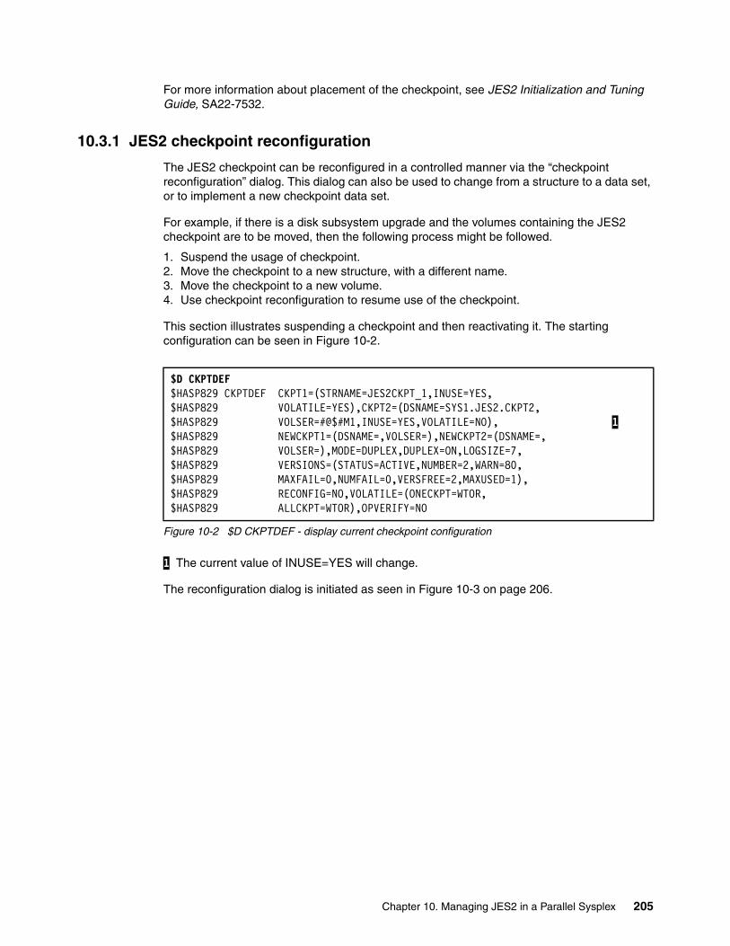
For more information about placement of the checkpoint, see JES2 Initialization and Tuning Guide, SA22-7532.
10.3.1 JES2 checkpoint reconfiguration
The JES2 checkpoint can be reconfigured in a controlled manner via the “checkpoint reconfiguration” dialog. This dialog can also be used to change from a structure to a data set, or to implement a new checkpoint data set.
For example, if there is a disk subsystem upgrade and the volumes containing the JES2 checkpoint are to be moved, then the following process might be followed.
1. Suspend the usage of checkpoint.2. Move the checkpoint to a new structure, with a different name.3. Move the checkpoint to a new volume.4. Use checkpoint reconfiguration to resume use of the checkpoint.
This section illustrates suspending a checkpoint and then reactivating it. The starting configuration can be seen in Figure 10-2.
Figure 10-2 $D CKPTDEF - display current checkpoint configuration
1 The current value of INUSE=YES will change.
The reconfiguration dialog is initiated as seen in Figure 10-3 on page 206.
$D CKPTDEF$HASP829 CKPTDEF CKPT1=(STRNAME=JES2CKPT_1,INUSE=YES, $HASP829 VOLATILE=YES),CKPT2=(DSNAME=SYS1.JES2.CKPT2, $HASP829 VOLSER=#@$#M1,INUSE=YES,VOLATILE=NO), 1$HASP829 NEWCKPT1=(DSNAME=,VOLSER=),NEWCKPT2=(DSNAME=, $HASP829 VOLSER=),MODE=DUPLEX,DUPLEX=ON,LOGSIZE=7, $HASP829 VERSIONS=(STATUS=ACTIVE,NUMBER=2,WARN=80, $HASP829 MAXFAIL=0,NUMFAIL=0,VERSFREE=2,MAXUSED=1), $HASP829 RECONFIG=NO,VOLATILE=(ONECKPT=WTOR, $HASP829 ALLCKPT=WTOR),OPVERIFY=NO
Chapter 10. Managing JES2 in a Parallel Sysplex 205
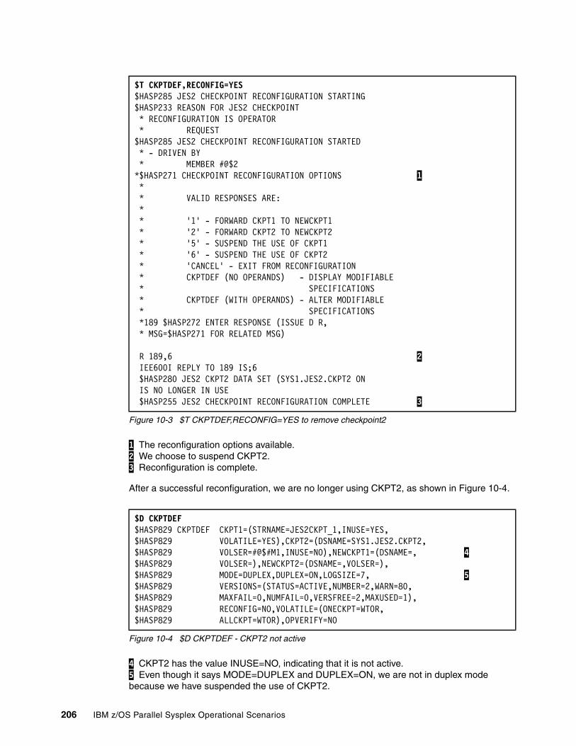
Figure 10-3 $T CKPTDEF,RECONFIG=YES to remove checkpoint2
1 The reconfiguration options available. 2 We choose to suspend CKPT2. 3 Reconfiguration is complete.
After a successful reconfiguration, we are no longer using CKPT2, as shown in Figure 10-4.
Figure 10-4 $D CKPTDEF - CKPT2 not active
4 CKPT2 has the value INUSE=NO, indicating that it is not active. 5 Even though it says MODE=DUPLEX and DUPLEX=ON, we are not in duplex mode because we have suspended the use of CKPT2.
$T CKPTDEF,RECONFIG=YES$HASP285 JES2 CHECKPOINT RECONFIGURATION STARTING $HASP233 REASON FOR JES2 CHECKPOINT * RECONFIGURATION IS OPERATOR * REQUEST $HASP285 JES2 CHECKPOINT RECONFIGURATION STARTED * - DRIVEN BY * MEMBER #@$2 *$HASP271 CHECKPOINT RECONFIGURATION OPTIONS 1 * * VALID RESPONSES ARE: * * '1' - FORWARD CKPT1 TO NEWCKPT1 * '2' - FORWARD CKPT2 TO NEWCKPT2 * '5' - SUSPEND THE USE OF CKPT1 * '6' - SUSPEND THE USE OF CKPT2 * 'CANCEL' - EXIT FROM RECONFIGURATION * CKPTDEF (NO OPERANDS) - DISPLAY MODIFIABLE * SPECIFICATIONS * CKPTDEF (WITH OPERANDS) - ALTER MODIFIABLE * SPECIFICATIONS *189 $HASP272 ENTER RESPONSE (ISSUE D R, * MSG=$HASP271 FOR RELATED MSG) R 189,6 2 IEE600I REPLY TO 189 IS;6 $HASP280 JES2 CKPT2 DATA SET (SYS1.JES2.CKPT2 ON IS NO LONGER IN USE $HASP255 JES2 CHECKPOINT RECONFIGURATION COMPLETE 3
$D CKPTDEF$HASP829 CKPTDEF CKPT1=(STRNAME=JES2CKPT_1,INUSE=YES, $HASP829 VOLATILE=YES),CKPT2=(DSNAME=SYS1.JES2.CKPT2, $HASP829 VOLSER=#@$#M1,INUSE=NO),NEWCKPT1=(DSNAME=, 4 $HASP829 VOLSER=),NEWCKPT2=(DSNAME=,VOLSER=), $HASP829 MODE=DUPLEX,DUPLEX=ON,LOGSIZE=7, 5 $HASP829 VERSIONS=(STATUS=ACTIVE,NUMBER=2,WARN=80, $HASP829 MAXFAIL=0,NUMFAIL=0,VERSFREE=2,MAXUSED=1), $HASP829 RECONFIG=NO,VOLATILE=(ONECKPT=WTOR, $HASP829 ALLCKPT=WTOR),OPVERIFY=NO
206 IBM z/OS Parallel Sysplex Operational Scenarios

Now we can move the volume to the new DASD subsystem and resume the use of CKPT2, as shown in Figure 10-4 on page 206.
Figure 10-5 $T CKPTDEF,RECONFIG=YES to resume using CKPT2
6 The available options. 7 This time option 8 was chosen, resume CKPT2. 8 A confirmation message is issued. 9 The reply CONT confirms this is the correct configuration. 10 Message indicating we are using CKPT2. 11 Checkpoint reconfiguration is complete.
$T CKPTDEF,RECONFIG=YES*$HASP285 JES2 CHECKPOINT RECONFIGURATION STARTING *$HASP233 REASON FOR JES2 CHECKPOINT * RECONFIGURATION IS OPERATOR * REQUEST *$HASP285 JES2 CHECKPOINT RECONFIGURATION STARTED * - DRIVEN BY MEMBER #@$2 *$HASP271 CHECKPOINT RECONFIGURATION OPTIONS 6 * * VALID RESPONSES ARE: * * '1' - FORWARD CKPT1 TO NEWCKPT1 * '8' - UPDATE AND START USING CKPT2 * 'CANCEL' - EXIT FROM RECONFIGURATION * CKPTDEF (NO OPERANDS) - DISPLAY MODIFIABLE * SPECIFICATIONS * CKPTDEF (WITH OPERANDS) - ALTER MODIFIABLE * SPECIFICATIONS *190 $HASP272 ENTER RESPONSE (ISSUE D R, * MSG=$HASP271 FOR RELATED MSG) SPECIFICATIONS R190,8 7 IEE600I REPLY TO 190 IS;8 *$HASP273 JES2 CKPT2 DATA SET WILL BE ASSIGNED TO 8 * * SYS1.JES2.CKPT2 ON #@$#M1 * * VALID RESPONSES ARE: * * 'CONT' - PROCEED WITH ASSIGNMENT * 'CANCEL' - EXIT FROM RECONFIGURATION * CKPTDEF (NO OPERANDS) - DISPLAY MODIFIABLE * SPECIFICATIONS * CKPTDEF (WITH OPERANDS) - ALTER MODIFIABLE * SPECIFICATIONS *191 $HASP272 ENTER RESPONSE (ISSUE D R, * MSG=$HASP273 FOR RELATED MSG) R 191,CONT 9 IEE600I REPLY TO 191 IS;CONT $HASP280 JES2 CKPT2 DATA SET (SYS1.JES2.CKPT2 ON 10 #@$#M1) IS NOW IN USE $HASP255 JES2 CHECKPOINT RECONFIGURATION COMPLETE 11
Chapter 10. Managing JES2 in a Parallel Sysplex 207
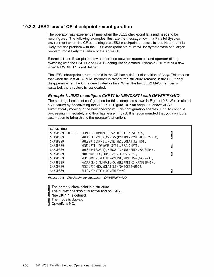
10.3.2 JES2 loss of CF checkpoint reconfiguration
The operator may experience times when the JES2 checkpoint fails and needs to be reconfigured. The following examples illustrate the message flow in a Parallel Sysplex environment when the CF containing the JES2 checkpoint structure is lost. Note that it is likely that the problem with the JES2 checkpoint structure will be symptomatic of a larger problem, most likely the failure of the entire CF.
Example 1 and Example 2 show a difference between automatic and operator dialog switching with the CKPT1 and CKPT2 configuration defined. Example 3 illustrates a flow when NEWCKPT1 is not defined.
The JES2 checkpoint structure held in the CF has a default disposition of keep. This means that when the last JES2 MAS member is closed, the structure remains in the CF. It only disappears when the CF is deactivated or fails. When the first JES2 MAS member is restarted, the structure is reallocated.
Example 1: JES2 reconfigure CKPT1 to NEWCKPT1 with OPVERIFY=NOThe starting checkpoint configuration for this example is shown in Figure 10-6. We simulated a CF failure by deactivating the CF LPAR. Figure 10-7 on page 209 shows JES2 automatically moving to the new checkpoint. This configuration enables JES2 to continue processing immediately and thus has lesser impact. It is recommended that you configure automation to bring this to the operator’s attention.
Figure 10-6 Checkpoint configuration - OPVERIFY=NO
1 The primary checkpoint is a structure. 2 The duplex checkpoint is active and on DASD. 3 NewCKPT1 is defined. 4 The mode is duplex. 5 Opverify is NO.
$D CKPTDEF $HASP829 CKPTDEF CKPT1=(STRNAME=JES2CKPT_1,INUSE=YES, 1 $HASP829 VOLATILE=YES),CKPT2=(DSNAME=SYS1.JES2.CKPT2, 2 $HASP829 VOLSER=#@$#M1,INUSE=YES,VOLATILE=NO), $HASP829 NEWCKPT1=(DSNAME=SYS1.JES2.CKPT1, 3 $HASP829 VOLSER=#@$#J1),NEWCKPT2=(DSNAME=,VOLSER=), $HASP829 MODE=DUPLEX,DUPLEX=ON,LOGSIZE=7, 4 $HASP829 VERSIONS=(STATUS=ACTIVE,NUMBER=2,WARN=80, $HASP829 MAXFAIL=0,NUMFAIL=0,VERSFREE=2,MAXUSED=1), $HASP829 RECONFIG=NO,VOLATILE=(ONECKPT=WTOR, $HASP829 ALLCKPT=WTOR),OPVERIFY=NO 5
208 IBM z/OS Parallel Sysplex Operational Scenarios
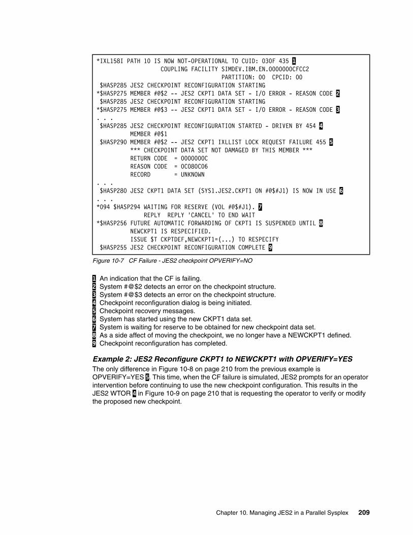
Figure 10-7 CF Failure - JES2 checkpoint OPVERIFY=NO
1 An indication that the CF is failing. 2 System #@$2 detects an error on the checkpoint structure. 3 System #@$3 detects an error on the checkpoint structure. 4 Checkpoint reconfiguration dialog is being initiated. 5 Checkpoint recovery messages. 6 System has started using the new CKPT1 data set. 7 System is waiting for reserve to be obtained for new checkpoint data set. 8 As a side affect of moving the checkpoint, we no longer have a NEWCKPT1 defined. 9 Checkpoint reconfiguration has completed.
Example 2: JES2 Reconfigure CKPT1 to NEWCKPT1 with OPVERIFY=YESThe only difference in Figure 10-8 on page 210 from the previous example is OPVERIFY=YES 5. This time, when the CF failure is simulated, JES2 prompts for an operator intervention before continuing to use the new checkpoint configuration. This results in the JES2 WTOR 4 in Figure 10-9 on page 210 that is requesting the operator to verify or modify the proposed new checkpoint.
*IXL158I PATH 10 IS NOW NOT-OPERATIONAL TO CUID: 030F 435 1 COUPLING FACILITY SIMDEV.IBM.EN.0000000CFCC2 PARTITION: 00 CPCID: 00 $HASP285 JES2 CHECKPOINT RECONFIGURATION STARTING *$HASP275 MEMBER #@$2 -- JES2 CKPT1 DATA SET - I/O ERROR - REASON CODE 2 $HASP285 JES2 CHECKPOINT RECONFIGURATION STARTING *$HASP275 MEMBER #@$3 -- JES2 CKPT1 DATA SET - I/O ERROR - REASON CODE 3 . . . $HASP285 JES2 CHECKPOINT RECONFIGURATION STARTED - DRIVEN BY 454 4 MEMBER #@$1 $HASP290 MEMBER #@$2 -- JES2 CKPT1 IXLLIST LOCK REQUEST FAILURE 455 5 *** CHECKPOINT DATA SET NOT DAMAGED BY THIS MEMBER *** RETURN CODE = 0000000C REASON CODE = 0C080C06 RECORD = UNKNOWN . . . $HASP280 JES2 CKPT1 DATA SET (SYS1.JES2.CKPT1 ON #@$#J1) IS NOW IN USE 6 . . . *094 $HASP294 WAITING FOR RESERVE (VOL #@$#J1). 7 REPLY REPLY 'CANCEL' TO END WAIT *$HASP256 FUTURE AUTOMATIC FORWARDING OF CKPT1 IS SUSPENDED UNTIL 8 NEWCKPT1 IS RESPECIFIED. ISSUE $T CKPTDEF,NEWCKPT1=(...) TO RESPECIFY $HASP255 JES2 CHECKPOINT RECONFIGURATION COMPLETE 9
Chapter 10. Managing JES2 in a Parallel Sysplex 209
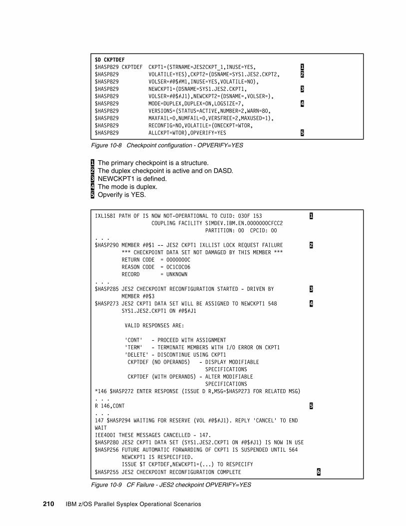
Figure 10-8 Checkpoint configuration - OPVERIFY=YES
1 The primary checkpoint is a structure. 2 The duplex checkpoint is active and on DASD. 3 NEWCKPT1 is defined. 4 The mode is duplex. 5 Opverify is YES.
Figure 10-9 CF Failure - JES2 checkpoint OPVERIFY=YES
$D CKPTDEF $HASP829 CKPTDEF CKPT1=(STRNAME=JES2CKPT_1,INUSE=YES, 1$HASP829 VOLATILE=YES),CKPT2=(DSNAME=SYS1.JES2.CKPT2, 2$HASP829 VOLSER=#@$#M1,INUSE=YES,VOLATILE=NO), $HASP829 NEWCKPT1=(DSNAME=SYS1.JES2.CKPT1, 3$HASP829 VOLSER=#@$#J1),NEWCKPT2=(DSNAME=,VOLSER=), $HASP829 MODE=DUPLEX,DUPLEX=ON,LOGSIZE=7, 4$HASP829 VERSIONS=(STATUS=ACTIVE,NUMBER=2,WARN=80, $HASP829 MAXFAIL=0,NUMFAIL=0,VERSFREE=2,MAXUSED=1), $HASP829 RECONFIG=NO,VOLATILE=(ONECKPT=WTOR, $HASP829 ALLCKPT=WTOR),OPVERIFY=YES 5
IXL158I PATH 0F IS NOW NOT-OPERATIONAL TO CUID: 030F 153 1 COUPLING FACILITY SIMDEV.IBM.EN.0000000CFCC2 PARTITION: 00 CPCID: 00 . . . $HASP290 MEMBER #@$1 -- JES2 CKPT1 IXLLIST LOCK REQUEST FAILURE 2 *** CHECKPOINT DATA SET NOT DAMAGED BY THIS MEMBER *** RETURN CODE = 0000000C REASON CODE = 0C1C0C06 RECORD = UNKNOWN . . . $HASP285 JES2 CHECKPOINT RECONFIGURATION STARTED - DRIVEN BY 3 MEMBER #@$3 $HASP273 JES2 CKPT1 DATA SET WILL BE ASSIGNED TO NEWCKPT1 548 4 SYS1.JES2.CKPT1 ON #@$#J1 VALID RESPONSES ARE: 'CONT' - PROCEED WITH ASSIGNMENT 'TERM' - TERMINATE MEMBERS WITH I/O ERROR ON CKPT1 'DELETE' - DISCONTINUE USING CKPT1 CKPTDEF (NO OPERANDS) - DISPLAY MODIFIABLE SPECIFICATIONS CKPTDEF (WITH OPERANDS) - ALTER MODIFIABLE SPECIFICATIONS *146 $HASP272 ENTER RESPONSE (ISSUE D R,MSG=$HASP273 FOR RELATED MSG) . . . R 146,CONT 5 . . . 147 $HASP294 WAITING FOR RESERVE (VOL #@$#J1). REPLY 'CANCEL' TO END WAIT IEE400I THESE MESSAGES CANCELLED - 147. $HASP280 JES2 CKPT1 DATA SET (SYS1.JES2.CKPT1 ON #@$#J1) IS NOW IN USE $HASP256 FUTURE AUTOMATIC FORWARDING OF CKPT1 IS SUSPENDED UNTIL 564 NEWCKPT1 IS RESPECIFIED. ISSUE $T CKPTDEF,NEWCKPT1=(...) TO RESPECIFY $HASP255 JES2 CHECKPOINT RECONFIGURATION COMPLETE 6
210 IBM z/OS Parallel Sysplex Operational Scenarios
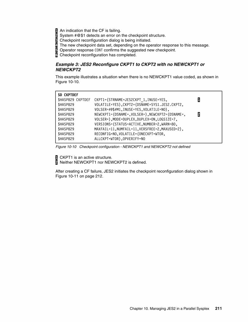
1 An indication that the CF is failing. 2 System #@$1 detects an error on the checkpoint structure. 3 Checkpoint reconfiguration dialog is being initiated. 4 The new checkpoint data set, depending on the operator response to this message. 5 Operator response CONT confirms the suggested new checkpoint. 6 Checkpoint reconfiguration has completed.
Example 3: JES2 Reconfigure CKPT1 to CKPT2 with no NEWCKPT1 or NEWCKPT2
This example illustrates a situation when there is no NEWCKPT1 value coded, as shown in Figure 10-10.
Figure 10-10 Checkpoint configuration - NEWCKPT1 and NEWCKPT2 not defined
1 CKPT1 is an active structure. 2 Neither NEWCKPT1 nor NEWCKPT2 is defined.
After creating a CF failure, JES2 initiates the checkpoint reconfiguration dialog shown in Figure 10-11 on page 212.
$D CKPTDEF $HASP829 CKPTDEF CKPT1=(STRNAME=JES2CKPT_1,INUSE=YES, 1$HASP829 VOLATILE=YES),CKPT2=(DSNAME=SYS1.JES2.CKPT2, $HASP829 VOLSER=#@$#M1,INUSE=YES,VOLATILE=NO), $HASP829 NEWCKPT1=(DSNAME=,VOLSER=),NEWCKPT2=(DSNAME=, 2$HASP829 VOLSER=),MODE=DUPLEX,DUPLEX=ON,LOGSIZE=7, $HASP829 VERSIONS=(STATUS=ACTIVE,NUMBER=2,WARN=80, $HASP829 MAXFAIL=11,NUMFAIL=11,VERSFREE=2,MAXUSED=2), $HASP829 RECONFIG=NO,VOLATILE=(ONECKPT=WTOR, $HASP829 ALLCKPT=WTOR),OPVERIFY=NO
Chapter 10. Managing JES2 in a Parallel Sysplex 211
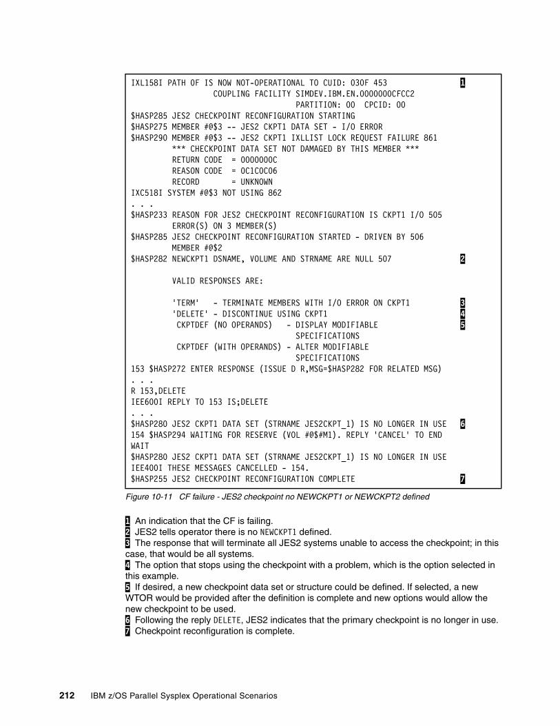
Figure 10-11 CF failure - JES2 checkpoint no NEWCKPT1 or NEWCKPT2 defined
1 An indication that the CF is failing. 2 JES2 tells operator there is no NEWCKPT1 defined. 3 The response that will terminate all JES2 systems unable to access the checkpoint; in this case, that would be all systems. 4 The option that stops using the checkpoint with a problem, which is the option selected in this example. 5 If desired, a new checkpoint data set or structure could be defined. If selected, a new WTOR would be provided after the definition is complete and new options would allow the new checkpoint to be used. 6 Following the reply DELETE, JES2 indicates that the primary checkpoint is no longer in use. 7 Checkpoint reconfiguration is complete.
IXL158I PATH 0F IS NOW NOT-OPERATIONAL TO CUID: 030F 453 1 COUPLING FACILITY SIMDEV.IBM.EN.0000000CFCC2 PARTITION: 00 CPCID: 00 $HASP285 JES2 CHECKPOINT RECONFIGURATION STARTING $HASP275 MEMBER #@$3 -- JES2 CKPT1 DATA SET - I/O ERROR $HASP290 MEMBER #@$3 -- JES2 CKPT1 IXLLIST LOCK REQUEST FAILURE 861 *** CHECKPOINT DATA SET NOT DAMAGED BY THIS MEMBER *** RETURN CODE = 0000000C REASON CODE = 0C1C0C06 RECORD = UNKNOWN IXC518I SYSTEM #@$3 NOT USING 862 . . . $HASP233 REASON FOR JES2 CHECKPOINT RECONFIGURATION IS CKPT1 I/O 505 ERROR(S) ON 3 MEMBER(S) $HASP285 JES2 CHECKPOINT RECONFIGURATION STARTED - DRIVEN BY 506 MEMBER #@$2 $HASP282 NEWCKPT1 DSNAME, VOLUME AND STRNAME ARE NULL 507 2 VALID RESPONSES ARE: 'TERM' - TERMINATE MEMBERS WITH I/O ERROR ON CKPT1 3 'DELETE' - DISCONTINUE USING CKPT1 4 CKPTDEF (NO OPERANDS) - DISPLAY MODIFIABLE 5 SPECIFICATIONS CKPTDEF (WITH OPERANDS) - ALTER MODIFIABLE SPECIFICATIONS 153 $HASP272 ENTER RESPONSE (ISSUE D R,MSG=$HASP282 FOR RELATED MSG) . . . R 153,DELETE IEE600I REPLY TO 153 IS;DELETE . . . $HASP280 JES2 CKPT1 DATA SET (STRNAME JES2CKPT_1) IS NO LONGER IN USE 6 154 $HASP294 WAITING FOR RESERVE (VOL #@$#M1). REPLY 'CANCEL' TO END WAIT $HASP280 JES2 CKPT1 DATA SET (STRNAME JES2CKPT_1) IS NO LONGER IN USE IEE400I THESE MESSAGES CANCELLED - 154. $HASP255 JES2 CHECKPOINT RECONFIGURATION COMPLETE 7
212 IBM z/OS Parallel Sysplex Operational Scenarios
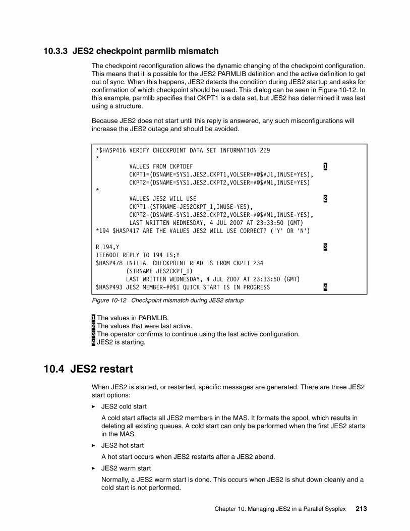
10.3.3 JES2 checkpoint parmlib mismatch
The checkpoint reconfiguration allows the dynamic changing of the checkpoint configuration. This means that it is possible for the JES2 PARMLIB definition and the active definition to get out of sync. When this happens, JES2 detects the condition during JES2 startup and asks for confirmation of which checkpoint should be used. This dialog can be seen in Figure 10-12. In this example, parmlib specifies that CKPT1 is a data set, but JES2 has determined it was last using a structure.
Because JES2 does not start until this reply is answered, any such misconfigurations will increase the JES2 outage and should be avoided.
Figure 10-12 Checkpoint mismatch during JES2 startup
1 The values in PARMLIB. 2 The values that were last active. 3 The operator confirms to continue using the last active configuration. 4 JES2 is starting.
10.4 JES2 restart
When JES2 is started, or restarted, specific messages are generated. There are three JES2 start options:
� JES2 cold start
A cold start affects all JES2 members in the MAS. It formats the spool, which results in deleting all existing queues. A cold start can only be performed when the first JES2 starts in the MAS.
� JES2 hot start
A hot start occurs when JES2 restarts after a JES2 abend.
� JES2 warm start
Normally, a JES2 warm start is done. This occurs when JES2 is shut down cleanly and a cold start is not performed.
*$HASP416 VERIFY CHECKPOINT DATA SET INFORMATION 229 * VALUES FROM CKPTDEF 1 CKPT1=(DSNAME=SYS1.JES2.CKPT1,VOLSER=#@$#J1,INUSE=YES), CKPT2=(DSNAME=SYS1.JES2.CKPT2,VOLSER=#@$#M1,INUSE=YES) * VALUES JES2 WILL USE 2 CKPT1=(STRNAME=JES2CKPT_1,INUSE=YES), CKPT2=(DSNAME=SYS1.JES2.CKPT2,VOLSER=#@$#M1,INUSE=YES), LAST WRITTEN WEDNESDAY, 4 JUL 2007 AT 23:33:50 (GMT) *194 $HASP417 ARE THE VALUES JES2 WILL USE CORRECT? ('Y' OR 'N') R 194,Y 3 IEE600I REPLY TO 194 IS;Y $HASP478 INITIAL CHECKPOINT READ IS FROM CKPT1 234 (STRNAME JES2CKPT_1) LAST WRITTEN WEDNESDAY, 4 JUL 2007 AT 23:33:50 (GMT) $HASP493 JES2 MEMBER-#@$1 QUICK START IS IN PROGRESS 4
Chapter 10. Managing JES2 in a Parallel Sysplex 213

The messages generated in a Parallel Sysplex differ, depending upon whether the restart is on the first JES2 MAS member or on an additional JES2.
The following examples are discussed in this chapter:
� Cold start on the first JES2 in a Parallel Sysplex MAS� Cold start on an additional JES2 in a Parallel Sysplex� Warm start on the first JES2 in a Parallel Sysplex� Warm start on an additional JES2 in a Parallel Sysplex MAS� Hot start on the first JES2 in a Parallel Sysplex MAS� Hot start on an additional JES2 in a Parallel Sysplex MAS
The configuration used is the recommended Parallel Sysplex configuration with two duplexed checkpoints: CKPT1 located in the CF, and CKPT2 on DASD.
10.4.1 JES2 cold start
This section describes two situations that can occur with JES2 cold start in Parallel Sysplex MAS.
Cold start on the first JES2 in a Parallel Sysplex MASA cold start on the first JES2 subsystem after a clean shutdown produces the usual cold start dialog, which the operator responds to. In Figure 10-13 on page 215, the structures exist prior to the JES2 cold start. If the structures were not allocated in the CF, there would be messages indicating the successful allocation of the checkpoint structures.
A cold start formats spool and the checkpoint data sets 6, 7, 8 and 9, which results in all input, output, and held queues being purged. If a cold start is required, consideration should be given to using the JES2 SPOOL offload and reload process to save the required queues.
Note: The message flow assumes NOREQ is specified in the options. Otherwise, a $HASP400 message is also issued, requiring a $S to start JES2 processing.
Note: If your site’s automation product starts JES2, it may interfere by replying to the JES2 startup messages when a cold start is attempted.
214 IBM z/OS Parallel Sysplex Operational Scenarios
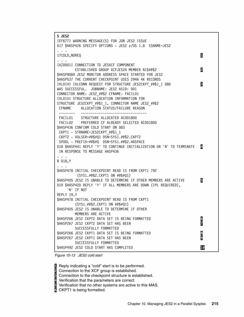
Figure 10-13 JES2 cold start
1 Reply indicating a “cold” start is to be performed. 2 Connection to the XCF group is established. 3 Connection to the checkpoint structure is established. 4 Verification that the parameters are correct. 5 Verification that no other systems are active to this MAS. 6 CKPT1 is being formatted.
S JES2IEF677I WARNING MESSAGE(S) FOR JOB JES2 ISSUE017 $HASP426 SPECIFY OPTIONS - JES2 z/OS 1.8 SSNAME=JES2. . .17COLD,NOREQ 1 . . .IXZ0001I CONNECTION TO JESXCF COMPONENT ESTABLISHED GROUP XCFJES2A MEMBER N1$#@$2 2 $HASP9084 JES2 MONITOR ADDRESS SPACE STARTED FOR JES2$HASP537 THE CURRENT CHECKPOINT USES 2946 4K RECORDSIXL014I IXLCONN REQUEST FOR STRUCTURE JES2CKPT_#@$1_1 080 3 WAS SUCCESSFUL. JOBNAME: JES2 ASID: 001CONNECTOR NAME: JES2_#@$2 CFNAME: FACIL01IXL015I STRUCTURE ALLOCATION INFORMATION FORSTRUCTURE JES2CKPT_#@$1_1, CONNECTOR NAME JES2_#@$2 CFNAME ALLOCATION STATUS/FAILURE REASON -------- --------------------------------- FACIL01 STRUCTURE ALLOCATED AC001800 FACIL02 PREFERRED CF ALREADY SELECTED AC001800$HASP436 CONFIRM COLD START ON 083 CKPT1 - STRNAME=JES2CKPT_#@$1_1 CKPT2 - VOLSER=#@$#Q1 DSN=SYS1.#@$2.CKPT2 SPOOL - PREFIX=#@$#Q DSN=SYS1.#@$2.HASPACE018 $HASP441 REPLY 'Y' TO CONTINUE INITIALIZATION OR 'N' TO TERMINATE 4 IN RESPONSE TO MESSAGE HASP436. . .R 018,Y. . .$HASP478 INITIAL CHECKPOINT READ IS FROM CKPT1 792 (SYS1.#@$2.CKPT1 ON #@$#Q1)$HASP405 JES2 IS UNABLE TO DETERMINE IF OTHER MEMBERS ARE ACTIVE 5 019 $HASP420 REPLY 'Y' IF ALL MEMBERS ARE DOWN (IPL REQUIRED), 'N' IF NOTREPLY 19,Y$HASP478 INITIAL CHECKPOINT READ IS FROM CKPT1 (SYS1.#@$2.CKPT1 ON #@$#Q1)$HASP405 JES2 IS UNABLE TO DETERMINE IF OTHER MEMBERS ARE ACTIVE$HASP266 JES2 CKPT2 DATA SET IS BEING FORMATTED 6 $HASP267 JES2 CKPT2 DATA SET HAS BEEN 7 SUCCESSFULLY FORMATTED$HASP266 JES2 CKPT1 DATA SET IS BEING FORMATTED 8 $HASP267 JES2 CKPT1 DATA SET HAS BEEN 9 SUCCESSFULLY FORMATTED$HASP492 JES2 COLD START HAS COMPLETED 10
Chapter 10. Managing JES2 in a Parallel Sysplex 215
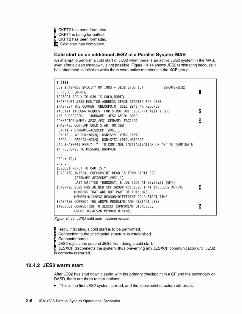
7 CKPT2 has been formatted. 8 CKPT1 is being formatted. 9 CKPT2 has been formatted. 10 Cold start has completed.
Cold start on an additional JES2 in a Parallel Sysplex MASAn attempt to perform a cold start of JES2 when there is an active JES2 system in the MAS, even after a clean shutdown, is not possible. Figure 10-14 shows JES2 terminating because it has attempted to initialize while there were active members in the XCF group.
Figure 10-14 JES2 cold start - second system
1 Reply indicating a cold start is to be performed. 2 Connection to the checkpoint structure is established. 3 Connector name. 4 JES2 rejects the second JES2 from doing a cold start. 5 JESXCF disconnects the system, thus preventing any JESXCF communication until JES2 is correctly restarted.
10.4.2 JES2 warm start
After JES2 has shut down cleanly, with the primary checkpoint in a CF and the secondary on DASD, there are three restart options:
� This is the first JES2 system started, and the checkpoint structure still exists.
S JES2039 $HASP426 SPECIFY OPTIONS - JES2 z/OS 1.7 SSNAME=JES2 R 39,COLD,NOREQ 1 IEE600I REPLY TO 039 IS;COLD,NOREQ $HASP9084 JES2 MONITOR ADDRESS SPACE STARTED FOR JES2 $HASP537 THE CURRENT CHECKPOINT USES 2946 4K RECORDS IXL014I IXLCONN REQUEST FOR STRUCTURE JES2CKPT_#@$1_1 386 2 WAS SUCCESSFUL. JOBNAME: JES2 ASID: 001C CONNECTOR NAME: JES2_#@$1 CFNAME: FACIL01 3 $HASP436 CONFIRM COLD START ON 388 CKPT1 - STRNAME=JES2CKPT_#@$1_1 CKPT2 - VOLSER=#@$#Q1 DSN=SYS1.#@$2.CKPT2 SPOOL - PREFIX=#@$#Q DSN=SYS1.#@$2.HASPACE 040 $HASP441 REPLY 'Y' TO CONTINUE INITIALIZATION OR 'N' TO TERMINATE IN RESPONSE TO MESSAGE HASP436 . . . REPLY 40,Y . . . IEE600I REPLY TO 040 IS;Y $HASP478 INITIAL CHECKPOINT READ IS FROM CKPT1 392 (STRNAME JES2CKPT_#@$1_1) LAST WRITTEN THURSDAY, 5 JUL 2007 AT 22:28:31 (GMT) $HASP792 JES2 HAS JOINED XCF GROUP XCFJES2B THAT INCLUDES ACTIVE 4 MEMBERS THAT ARE NOT PART OF THIS MAS MEMBER=N1$#@$2,REASON=DIFFERENT COLD START TIME $HASP428 CORRECT THE ABOVE PROBLEMS AND RESTART JES2 IXZ0002I CONNECTION TO JESXCF COMPONENT DISABLED, 5 GROUP XCFJES2B MEMBER N1$#@$1
216 IBM z/OS Parallel Sysplex Operational Scenarios
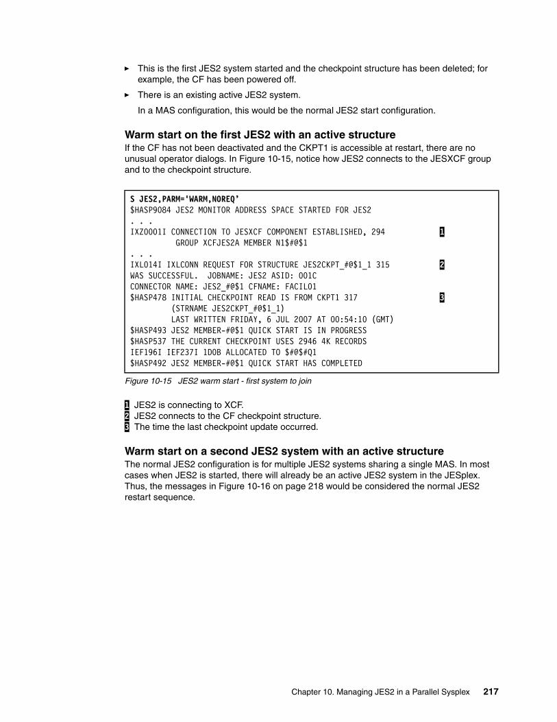
� This is the first JES2 system started and the checkpoint structure has been deleted; for example, the CF has been powered off.
� There is an existing active JES2 system.
In a MAS configuration, this would be the normal JES2 start configuration.
Warm start on the first JES2 with an active structureIf the CF has not been deactivated and the CKPT1 is accessible at restart, there are no unusual operator dialogs. In Figure 10-15, notice how JES2 connects to the JESXCF group and to the checkpoint structure.
Figure 10-15 JES2 warm start - first system to join
1 JES2 is connecting to XCF. 2 JES2 connects to the CF checkpoint structure. 3 The time the last checkpoint update occurred.
Warm start on a second JES2 system with an active structureThe normal JES2 configuration is for multiple JES2 systems sharing a single MAS. In most cases when JES2 is started, there will already be an active JES2 system in the JESplex. Thus, the messages in Figure 10-16 on page 218 would be considered the normal JES2 restart sequence.
S JES2,PARM='WARM,NOREQ’$HASP9084 JES2 MONITOR ADDRESS SPACE STARTED FOR JES2 . . . IXZ0001I CONNECTION TO JESXCF COMPONENT ESTABLISHED, 294 1 GROUP XCFJES2A MEMBER N1$#@$1 . . . IXL014I IXLCONN REQUEST FOR STRUCTURE JES2CKPT_#@$1_1 315 2 WAS SUCCESSFUL. JOBNAME: JES2 ASID: 001C CONNECTOR NAME: JES2_#@$1 CFNAME: FACIL01 $HASP478 INITIAL CHECKPOINT READ IS FROM CKPT1 317 3 (STRNAME JES2CKPT_#@$1_1) LAST WRITTEN FRIDAY, 6 JUL 2007 AT 00:54:10 (GMT) $HASP493 JES2 MEMBER-#@$1 QUICK START IS IN PROGRESS $HASP537 THE CURRENT CHECKPOINT USES 2946 4K RECORDS IEF196I IEF237I 1D0B ALLOCATED TO $#@$#Q1 $HASP492 JES2 MEMBER-#@$1 QUICK START HAS COMPLETED
Chapter 10. Managing JES2 in a Parallel Sysplex 217

Figure 10-16 JES2 warm start - second system to join
1 JES2 is connecting to XCF. 2 JES2 connects to the CF checkpoint structure. 3 JES2 reads the checkpoint data.
Warm start on the first JES2 with no active structureThis scenario is more complex. The checkpoint data in the CF is not available, for example following a power outage in which all CF structures were lost. In this situation, CKPT1 is lost and only the DASD copy (CKPT2) is available.
In Figure 10-17 on page 219, JES2 discovers that the CKPT1 structure is empty. z/OS then reallocates an empty structure, which JES2 attempts to connect to. JES2 asks the operator to confirm the parameters in use or to change them. The values are correct and the operator continues with initialization. Because JES2 cannot read CKPT1, it reads CKPT2 and the warm start continues normally because CKPT2 is a duplexed copy of CKPT1.
S JES2,PARM='WARM,NOREQ'$HASP9084 JES2 MONITOR ADDRESS SPACE STARTED FOR JES2 . . . IXZ0001I CONNECTION TO JESXCF COMPONENT ESTABLISHED, 294 1 GROUP XCFJES2A MEMBER N1$#@$1 . . . IXL014I IXLCONN REQUEST FOR STRUCTURE JES2CKPT_#@$1_1 315 2 WAS SUCCESSFUL. JOBNAME: JES2 ASID: 001C CONNECTOR NAME: JES2_#@$1 CFNAME: FACIL01 $HASP478 INITIAL CHECKPOINT READ IS FROM CKPT1 317 3 (STRNAME JES2CKPT_#@$1_1) LAST WRITTEN FRIDAY, 6 JUL 2007 AT 00:54:10 (GMT) $HASP493 JES2 MEMBER-#@$1 QUICK START IS IN PROGRESS $HASP537 THE CURRENT CHECKPOINT USES 2946 4K RECORDS IEF196I IEF237I 1D0B ALLOCATED TO $#@$#Q1 $HASP492 JES2 MEMBER-#@$1 QUICK START HAS COMPLETED
Note: If this were a scheduled outage, it would be good practice to use the checkpoint reconfiguration dialog to suspend the use of the CF checkpoint structure.
218 IBM z/OS Parallel Sysplex Operational Scenarios
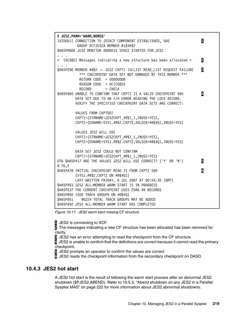
Figure 10-17 JES2 warm start missing CF structure
1 JES2 is connecting to XCF. 2 The messages indicating a new CF structure has been allocated has been removed for clarity. 3 JES2 has an error attempting to read the checkpoint from the CF structure. 4 JES2 is unable to confirm that the definitions are correct because it cannot read the primary checkpoint. 5 JES2 prompts an operator to confirm the values are correct. 6 JES2 reads the checkpoint information from the secondary checkpoint on DASD.
10.4.3 JES2 hot start
A JES2 hot start is the result of following the warm start process after an abnormal JES2 shutdown ($PJES2,ABEND). Refer to 10.5.3, “Abend shutdown on any JES2 in a Parallel Sysplex MAS” on page 222 for more information about JES2 abnormal shutdowns.
S JES2,PARM='WARM,NOREQ'IXZ0001I CONNECTION TO JESXCF COMPONENT ESTABLISHED, 560 1 GROUP XCFJES2A MEMBER N1$#@$2 $HASP9084 JES2 MONITOR ADDRESS SPACE STARTED FOR JES2 . . . < IXC582I Messages indicating a new structure has been allocated > 2 . . . $HASP290 MEMBER #@$2 -- JES2 CKPT1 IXLLIST READ_LIST REQUEST FAILURE 3 *** CHECKPOINT DATA SET NOT DAMAGED BY THIS MEMBER *** RETURN CODE = 00000008 REASON CODE = 0C1C0825 RECORD = CHECK $HASP460 UNABLE TO CONFIRM THAT CKPT1 IS A VALID CHECKPOINT 585 4 DATA SET DUE TO AN I/O ERROR READING THE LOCK RECORD. VERIFY THE SPECIFIED CHECKPOINT DATA SETS ARE CORRECT: VALUES FROM CKPTDEF CKPT1=(STRNAME=JES2CKPT_#@$1_1,INUSE=YES), CKPT2=(DSNAME=SYS1.#@$2.CKPT2,VOLSER=#@$#Q1,INUSE=YES) VALUES JES2 WILL USE CKPT1=(STRNAME=JES2CKPT_#@$1_1,INUSE=YES), CKPT2=(DSNAME=SYS1.#@$2.CKPT2,VOLSER=#@$#Q1,INUSE=YES) DATA SET JES2 COULD NOT CONFIRM CKPT1=(STRNAME=JES2CKPT_#@$1_1,INUSE=YES) 076 $HASP417 ARE THE VALUES JES2 WILL USE CORRECT? ('Y' OR 'N') 5 R 76,Y $HASP478 INITIAL CHECKPOINT READ IS FROM CKPT2 590 6 (SYS1.#@$2.CKPT2 ON #@$#Q1) LAST WRITTEN FRIDAY, 6 JUL 2007 AT 00:54:30 (GMT) $HASP493 JES2 ALL-MEMBER WARM START IS IN PROGRESS $HASP537 THE CURRENT CHECKPOINT USES 2946 4K RECORDS $HASP850 1500 TRACK GROUPS ON #@$#Q1 $HASP851 96224 TOTAL TRACK GROUPS MAY BE ADDED $HASP492 JES2 ALL-MEMBER WARM START HAS COMPLETED
Chapter 10. Managing JES2 in a Parallel Sysplex 219
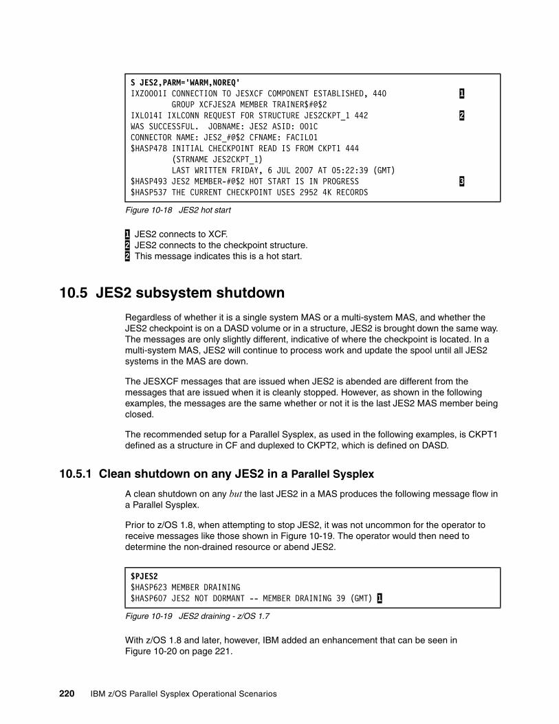
Figure 10-18 JES2 hot start
1 JES2 connects to XCF. 2 JES2 connects to the checkpoint structure. 2 This message indicates this is a hot start.
10.5 JES2 subsystem shutdown
Regardless of whether it is a single system MAS or a multi-system MAS, and whether the JES2 checkpoint is on a DASD volume or in a structure, JES2 is brought down the same way. The messages are only slightly different, indicative of where the checkpoint is located. In a multi-system MAS, JES2 will continue to process work and update the spool until all JES2 systems in the MAS are down.
The JESXCF messages that are issued when JES2 is abended are different from the messages that are issued when it is cleanly stopped. However, as shown in the following examples, the messages are the same whether or not it is the last JES2 MAS member being closed.
The recommended setup for a Parallel Sysplex, as used in the following examples, is CKPT1 defined as a structure in CF and duplexed to CKPT2, which is defined on DASD.
10.5.1 Clean shutdown on any JES2 in a Parallel Sysplex
A clean shutdown on any but the last JES2 in a MAS produces the following message flow in a Parallel Sysplex.
Prior to z/OS 1.8, when attempting to stop JES2, it was not uncommon for the operator to receive messages like those shown in Figure 10-19. The operator would then need to determine the non-drained resource or abend JES2.
Figure 10-19 JES2 draining - z/OS 1.7
With z/OS 1.8 and later, however, IBM added an enhancement that can be seen in Figure 10-20 on page 221.
S JES2,PARM='WARM,NOREQ'IXZ0001I CONNECTION TO JESXCF COMPONENT ESTABLISHED, 440 1 GROUP XCFJES2A MEMBER TRAINER$#@$2 IXL014I IXLCONN REQUEST FOR STRUCTURE JES2CKPT_1 442 2 WAS SUCCESSFUL. JOBNAME: JES2 ASID: 001C CONNECTOR NAME: JES2_#@$2 CFNAME: FACIL01 $HASP478 INITIAL CHECKPOINT READ IS FROM CKPT1 444 (STRNAME JES2CKPT_1) LAST WRITTEN FRIDAY, 6 JUL 2007 AT 05:22:39 (GMT) $HASP493 JES2 MEMBER-#@$2 HOT START IS IN PROGRESS 3 $HASP537 THE CURRENT CHECKPOINT USES 2952 4K RECORDS
$PJES2 $HASP623 MEMBER DRAINING $HASP607 JES2 NOT DORMANT -- MEMBER DRAINING 39 (GMT) 1
220 IBM z/OS Parallel Sysplex Operational Scenarios
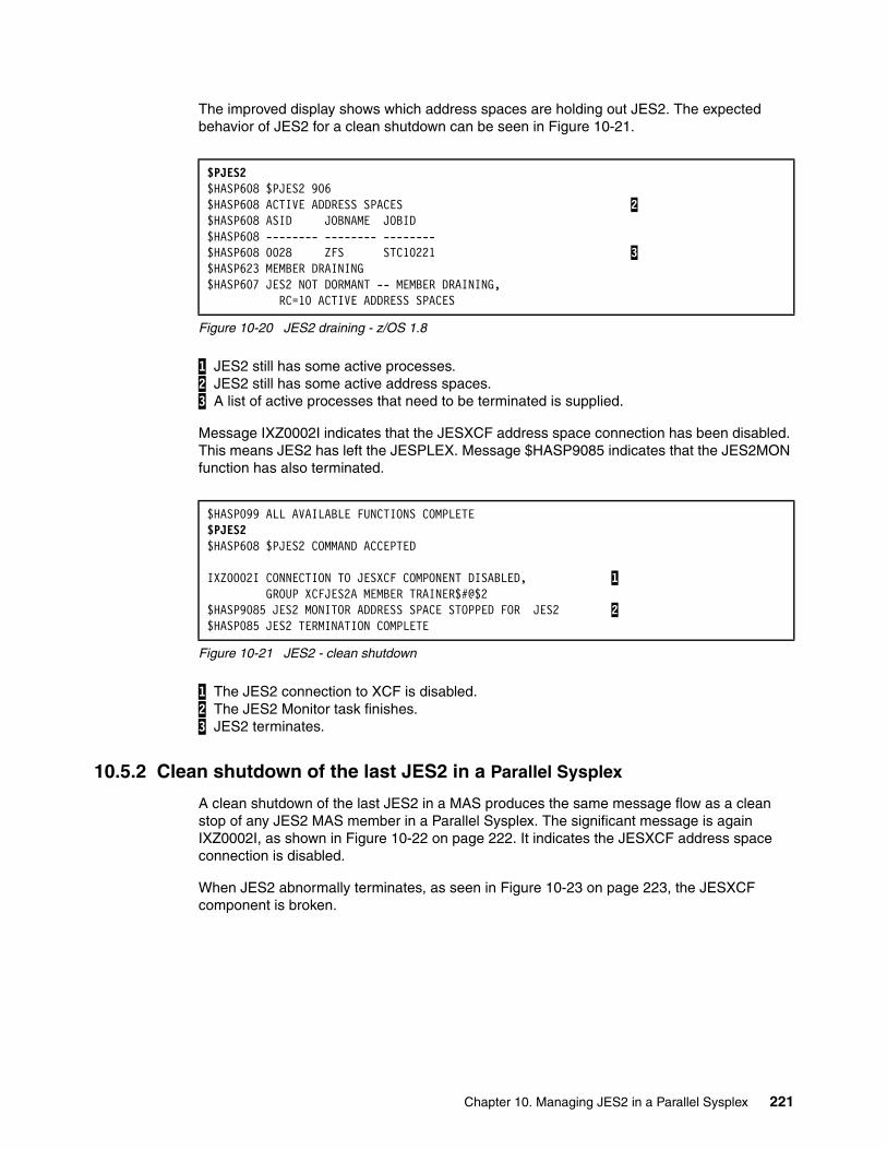
The improved display shows which address spaces are holding out JES2. The expected behavior of JES2 for a clean shutdown can be seen in Figure 10-21.
Figure 10-20 JES2 draining - z/OS 1.8
1 JES2 still has some active processes. 2 JES2 still has some active address spaces. 3 A list of active processes that need to be terminated is supplied.
Message IXZ0002I indicates that the JESXCF address space connection has been disabled. This means JES2 has left the JESPLEX. Message $HASP9085 indicates that the JES2MON function has also terminated.
Figure 10-21 JES2 - clean shutdown
1 The JES2 connection to XCF is disabled. 2 The JES2 Monitor task finishes. 3 JES2 terminates.
10.5.2 Clean shutdown of the last JES2 in a Parallel Sysplex
A clean shutdown of the last JES2 in a MAS produces the same message flow as a clean stop of any JES2 MAS member in a Parallel Sysplex. The significant message is again IXZ0002I, as shown in Figure 10-22 on page 222. It indicates the JESXCF address space connection is disabled.
When JES2 abnormally terminates, as seen in Figure 10-23 on page 223, the JESXCF component is broken.
$PJES2 $HASP608 $PJES2 906 $HASP608 ACTIVE ADDRESS SPACES 2 $HASP608 ASID JOBNAME JOBID $HASP608 -------- -------- -------- $HASP608 0028 ZFS STC10221 3 $HASP623 MEMBER DRAINING $HASP607 JES2 NOT DORMANT -- MEMBER DRAINING, RC=10 ACTIVE ADDRESS SPACES
$HASP099 ALL AVAILABLE FUNCTIONS COMPLETE $PJES2 $HASP608 $PJES2 COMMAND ACCEPTED IXZ0002I CONNECTION TO JESXCF COMPONENT DISABLED, 1 GROUP XCFJES2A MEMBER TRAINER$#@$2 $HASP9085 JES2 MONITOR ADDRESS SPACE STOPPED FOR JES2 2$HASP085 JES2 TERMINATION COMPLETE
Chapter 10. Managing JES2 in a Parallel Sysplex 221

Figure 10-22 $PJES2, last system in the jesplex
1 The JESXCF is connection is stopped.
10.5.3 Abend shutdown on any JES2 in a Parallel Sysplex MAS
An abend shutdown on any JES2 system, or a catastrophic failure of JES2 in a MAS, produces the following message flow in a Parallel Sysplex.
The significant message is IXZ0003I 1, as seen in Figure 10-23 on page 223, indicating the connection to the JESXCF address space is broken.
04.17.25 #@$2 $PJES2 04.17.25 #@$2 $HASP608 $PJES2 COMMAND ACCEPTED 04.17.25 #@$2 *CNZ4201E SYSLOG HAS FAILED 04.17.25 #@$2 IEE043I A SYSTEM LOG DATA SET HAS BEEN QUEUED TO SYSOUT CLASS L 04.17.25 #@$2 *IEE037D LOG NOT ACTIVE 04.17.26 #@$2 IXZ0002I CONNECTION TO JESXCF COMPONENT DISABLED, 1 GROUP XCFJES2A MEMBER TRAINER$#@$2 04.17.26 #@$2 $HASP9085 JES2 MONITOR ADDRESS SPACE STOPPED FOR JES2 04.17.31 #@$2 $HASP085 JES2 TERMINATION COMPLETE
222 IBM z/OS Parallel Sysplex Operational Scenarios
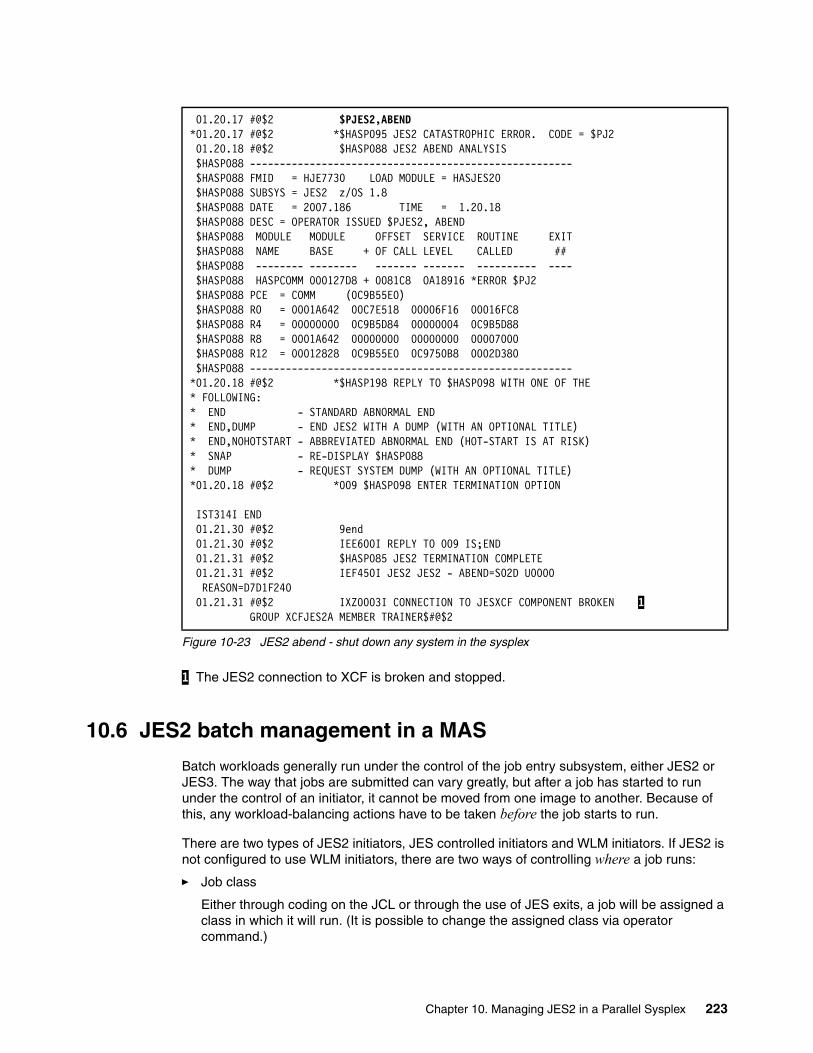
Figure 10-23 JES2 abend - shut down any system in the sysplex
1 The JES2 connection to XCF is broken and stopped.
10.6 JES2 batch management in a MAS
Batch workloads generally run under the control of the job entry subsystem, either JES2 or JES3. The way that jobs are submitted can vary greatly, but after a job has started to run under the control of an initiator, it cannot be moved from one image to another. Because of this, any workload-balancing actions have to be taken before the job starts to run.
There are two types of JES2 initiators, JES controlled initiators and WLM initiators. If JES2 is not configured to use WLM initiators, there are two ways of controlling where a job runs:
� Job class
Either through coding on the JCL or through the use of JES exits, a job will be assigned a class in which it will run. (It is possible to change the assigned class via operator command.)
01.20.17 #@$2 $PJES2,ABEND *01.20.17 #@$2 *$HASP095 JES2 CATASTROPHIC ERROR. CODE = $PJ2 01.20.18 #@$2 $HASP088 JES2 ABEND ANALYSIS $HASP088 ------------------------------------------------------ $HASP088 FMID = HJE7730 LOAD MODULE = HASJES20 $HASP088 SUBSYS = JES2 z/OS 1.8 $HASP088 DATE = 2007.186 TIME = 1.20.18 $HASP088 DESC = OPERATOR ISSUED $PJES2, ABEND $HASP088 MODULE MODULE OFFSET SERVICE ROUTINE EXIT $HASP088 NAME BASE + OF CALL LEVEL CALLED ## $HASP088 -------- -------- ------- ------- ---------- ---- $HASP088 HASPCOMM 000127D8 + 0081C8 OA18916 *ERROR $PJ2 $HASP088 PCE = COMM (0C9B55E0) $HASP088 R0 = 0001A642 00C7E518 00006F16 00016FC8 $HASP088 R4 = 00000000 0C9B5D84 00000004 0C9B5D88 $HASP088 R8 = 0001A642 00000000 00000000 00007000 $HASP088 R12 = 00012828 0C9B55E0 0C9750B8 0002D380 $HASP088 ------------------------------------------------------ *01.20.18 #@$2 *$HASP198 REPLY TO $HASP098 WITH ONE OF THE * FOLLOWING: * END - STANDARD ABNORMAL END * END,DUMP - END JES2 WITH A DUMP (WITH AN OPTIONAL TITLE) * END,NOHOTSTART - ABBREVIATED ABNORMAL END (HOT-START IS AT RISK) * SNAP - RE-DISPLAY $HASP088 * DUMP - REQUEST SYSTEM DUMP (WITH AN OPTIONAL TITLE) *01.20.18 #@$2 *009 $HASP098 ENTER TERMINATION OPTION IST314I END 01.21.30 #@$2 9end 01.21.30 #@$2 IEE600I REPLY TO 009 IS;END 01.21.31 #@$2 $HASP085 JES2 TERMINATION COMPLETE 01.21.31 #@$2 IEF450I JES2 JES2 - ABEND=S02D U0000 REASON=D7D1F240 01.21.31 #@$2 IXZ0003I CONNECTION TO JESXCF COMPONENT BROKEN 1 GROUP XCFJES2A MEMBER TRAINER$#@$2
Chapter 10. Managing JES2 in a Parallel Sysplex 223
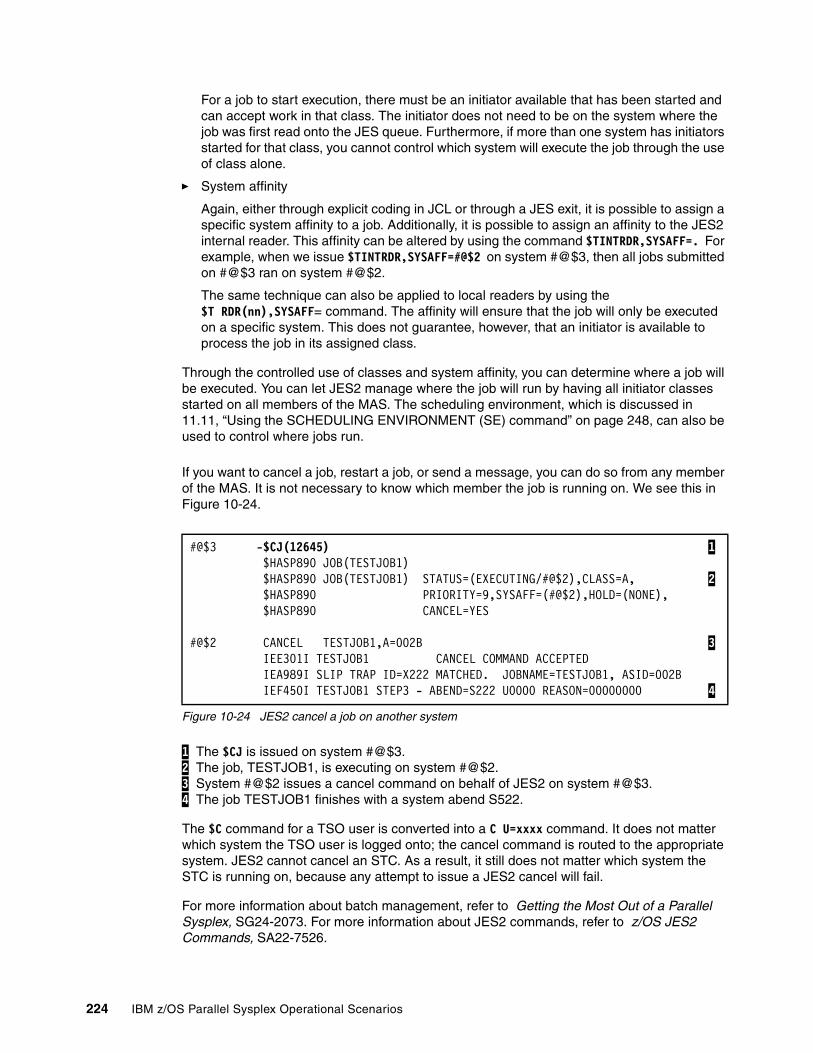
For a job to start execution, there must be an initiator available that has been started and can accept work in that class. The initiator does not need to be on the system where the job was first read onto the JES queue. Furthermore, if more than one system has initiators started for that class, you cannot control which system will execute the job through the use of class alone.
� System affinity
Again, either through explicit coding in JCL or through a JES exit, it is possible to assign a specific system affinity to a job. Additionally, it is possible to assign an affinity to the JES2 internal reader. This affinity can be altered by using the command $TINTRDR,SYSAFF=. For example, when we issue $TINTRDR,SYSAFF=#@$2 on system #@$3, then all jobs submitted on #@$3 ran on system #@$2.
The same technique can also be applied to local readers by using the $T RDR(nn),SYSAFF= command. The affinity will ensure that the job will only be executed on a specific system. This does not guarantee, however, that an initiator is available to process the job in its assigned class.
Through the controlled use of classes and system affinity, you can determine where a job will be executed. You can let JES2 manage where the job will run by having all initiator classes started on all members of the MAS. The scheduling environment, which is discussed in 11.11, “Using the SCHEDULING ENVIRONMENT (SE) command” on page 248, can also be used to control where jobs run.
If you want to cancel a job, restart a job, or send a message, you can do so from any member of the MAS. It is not necessary to know which member the job is running on. We see this in Figure 10-24.
Figure 10-24 JES2 cancel a job on another system
1 The $CJ is issued on system #@$3. 2 The job, TESTJOB1, is executing on system #@$2. 3 System #@$2 issues a cancel command on behalf of JES2 on system #@$3. 4 The job TESTJOB1 finishes with a system abend S522.
The $C command for a TSO user is converted into a C U=xxxx command. It does not matter which system the TSO user is logged onto; the cancel command is routed to the appropriate system. JES2 cannot cancel an STC. As a result, it still does not matter which system the STC is running on, because any attempt to issue a JES2 cancel will fail.
For more information about batch management, refer to Getting the Most Out of a Parallel Sysplex, SG24-2073. For more information about JES2 commands, refer to z/OS JES2 Commands, SA22-7526.
#@$3 -$CJ(12645) 1 $HASP890 JOB(TESTJOB1) $HASP890 JOB(TESTJOB1) STATUS=(EXECUTING/#@$2),CLASS=A, 2 $HASP890 PRIORITY=9,SYSAFF=(#@$2),HOLD=(NONE), $HASP890 CANCEL=YES
#@$2 CANCEL TESTJOB1,A=002B 3 IEE301I TESTJOB1 CANCEL COMMAND ACCEPTED IEA989I SLIP TRAP ID=X222 MATCHED. JOBNAME=TESTJOB1, ASID=002B IEF450I TESTJOB1 STEP3 - ABEND=S222 U0000 REASON=00000000 4
224 IBM z/OS Parallel Sysplex Operational Scenarios
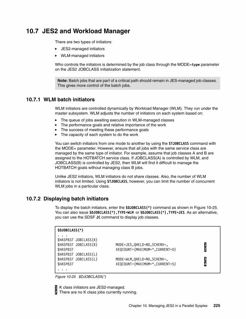
10.7 JES2 and Workload Manager
There are two types of initiators:
� JES2-managed initiators
� WLM-managed initiators
Who controls the initiators is determined by the job class through the MODE=type parameter on the JES2 JOBCLASS initialization statement.
10.7.1 WLM batch initiators
WLM initiators are controlled dynamically by Workload Manager (WLM). They run under the master subsystem. WLM adjusts the number of initiators on each system based on:
� The queue of jobs awaiting execution in WLM-managed classes� The performance goals and relative importance of the work� The success of meeting these performance goals� The capacity of each system to do the work
You can switch initiators from one mode to another by using the $TJOBCLASS command with the MODE= parameter. However, ensure that all jobs with the same service class are managed by the same type of initiator. For example, assume that job classes A and B are assigned to the HOTBATCH service class. If JOBCLASS(A) is controlled by WLM, and JOBCLASS(B) is controlled by JES2, then WLM will find it difficult to manage the HOTBATCH goals without managing class B jobs.
Unlike JES2 initiators, WLM initiators do not share classes. Also, the number of WLM initiators is not limited. Using $TJOBCLASS, however, you can limit the number of concurrent WLM jobs in a particular class.
10.7.2 Displaying batch initiators
To display the batch initiators, enter the $DJOBCLASS(*) command as shown in Figure 10-25. You can also issue $DJOBCLASS(*),TYPE=WLM or $DJOBCLASS(*),TYPE=JES. As an alternative, you can use the SDSF JC command to display job classes.
Figure 10-25 $DJOBCLASS(*)
1 K class initiators are JES2-managed. 2 There are no K class jobs currently running.
Note: Batch jobs that are part of a critical path should remain in JES-managed job classes. This gives more control of the batch jobs.
$DJOBCLASS(*). . .$HASP837 JOBCLASS(K)$HASP837 JOBCLASS(K) MODE=JES,QHELD=NO,SCHENV=, 1$HASP837 XEQCOUNT=(MAXIMUM=*,CURRENT=0) 2$HASP837 JOBCLASS(L)$HASP837 JOBCLASS(L) MODE=WLM,QHELD=NO,SCHENV=, 3$HASP837 XEQCOUNT=(MAXIMUM=*,CURRENT=5) 4. . .
Chapter 10. Managing JES2 in a Parallel Sysplex 225
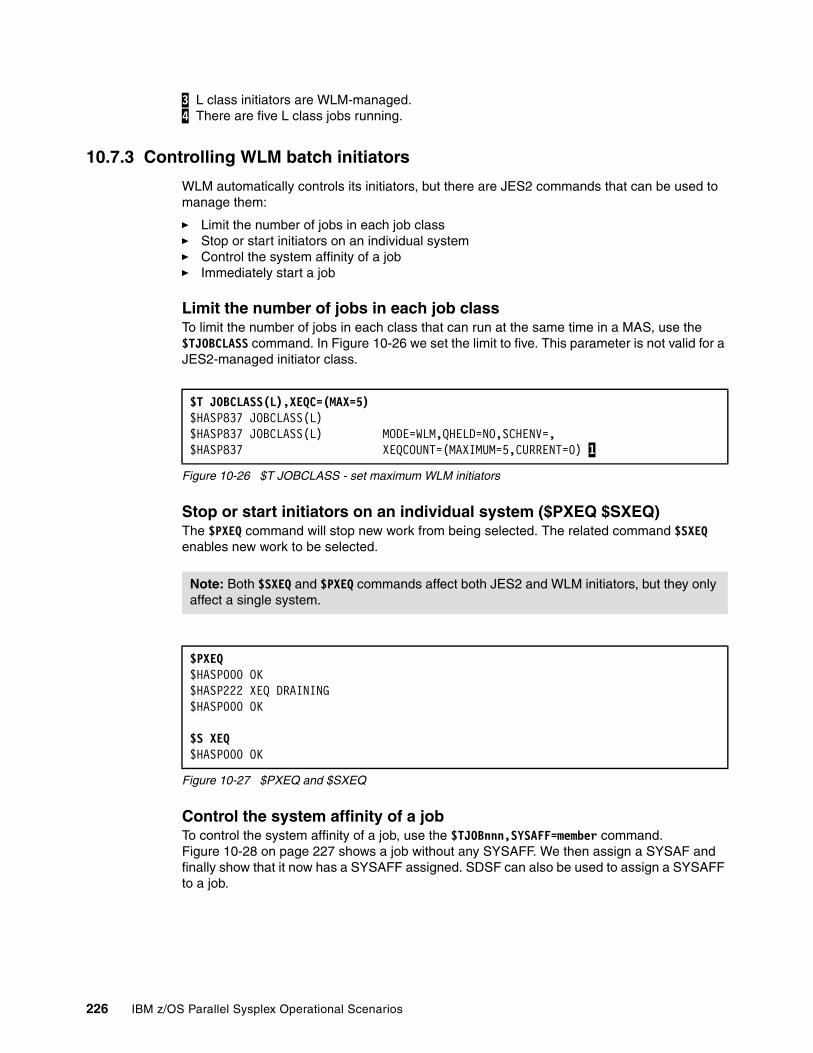
3 L class initiators are WLM-managed. 4 There are five L class jobs running.
10.7.3 Controlling WLM batch initiators
WLM automatically controls its initiators, but there are JES2 commands that can be used to manage them:
� Limit the number of jobs in each job class� Stop or start initiators on an individual system� Control the system affinity of a job� Immediately start a job
Limit the number of jobs in each job classTo limit the number of jobs in each class that can run at the same time in a MAS, use the $TJOBCLASS command. In Figure 10-26 we set the limit to five. This parameter is not valid for a JES2-managed initiator class.
Figure 10-26 $T JOBCLASS - set maximum WLM initiators
Stop or start initiators on an individual system ($PXEQ $SXEQ)The $PXEQ command will stop new work from being selected. The related command $SXEQ enables new work to be selected.
Figure 10-27 $PXEQ and $SXEQ
Control the system affinity of a jobTo control the system affinity of a job, use the $TJOBnnn,SYSAFF=member command. Figure 10-28 on page 227 shows a job without any SYSAFF. We then assign a SYSAF and finally show that it now has a SYSAFF assigned. SDSF can also be used to assign a SYSAFF to a job.
$T JOBCLASS(L),XEQC=(MAX=5)$HASP837 JOBCLASS(L)$HASP837 JOBCLASS(L) MODE=WLM,QHELD=NO,SCHENV=,$HASP837 XEQCOUNT=(MAXIMUM=5,CURRENT=0) 1
Note: Both $SXEQ and $PXEQ commands affect both JES2 and WLM initiators, but they only affect a single system.
$PXEQ$HASP000 OK$HASP222 XEQ DRAINING$HASP000 OK
$S XEQ$HASP000 OK
226 IBM z/OS Parallel Sysplex Operational Scenarios
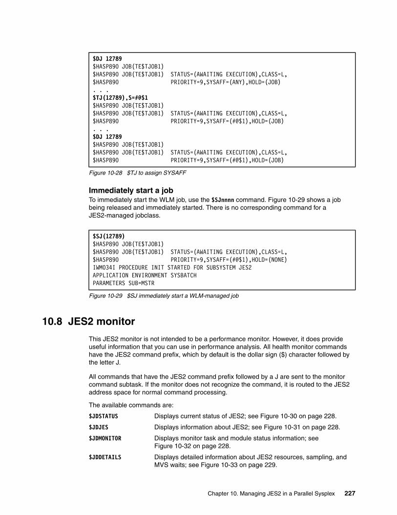
Figure 10-28 $TJ to assign SYSAFF
Immediately start a jobTo immediately start the WLM job, use the $SJnnnn command. Figure 10-29 shows a job being released and immediately started. There is no corresponding command for a JES2-managed jobclass.
Figure 10-29 $SJ immediately start a WLM-managed job
10.8 JES2 monitor
This JES2 monitor is not intended to be a performance monitor. However, it does provide useful information that you can use in performance analysis. All health monitor commands have the JES2 command prefix, which by default is the dollar sign ($) character followed by the letter J.
All commands that have the JES2 command prefix followed by a J are sent to the monitor command subtask. If the monitor does not recognize the command, it is routed to the JES2 address space for normal command processing.
The available commands are:
$JDSTATUS Displays current status of JES2; see Figure 10-30 on page 228.
$JDJES Displays information about JES2; see Figure 10-31 on page 228.
$JDMONITOR Displays monitor task and module status information; see Figure 10-32 on page 228.
$JDDETAILS Displays detailed information about JES2 resources, sampling, and MVS waits; see Figure 10-33 on page 229.
$DJ 12789$HASP890 JOB(TE$TJOB1)$HASP890 JOB(TE$TJOB1) STATUS=(AWAITING EXECUTION),CLASS=L,$HASP890 PRIORITY=9,SYSAFF=(ANY),HOLD=(JOB). . .$TJ(12789),S=#@$1$HASP890 JOB(TE$TJOB1)$HASP890 JOB(TE$TJOB1) STATUS=(AWAITING EXECUTION),CLASS=L,$HASP890 PRIORITY=9,SYSAFF=(#@$1),HOLD=(JOB). . .$DJ 12789$HASP890 JOB(TE$TJOB1)$HASP890 JOB(TE$TJOB1) STATUS=(AWAITING EXECUTION),CLASS=L,$HASP890 PRIORITY=9,SYSAFF=(#@$1),HOLD=(JOB)
$SJ(12789)$HASP890 JOB(TE$TJOB1)$HASP890 JOB(TE$TJOB1) STATUS=(AWAITING EXECUTION),CLASS=L,$HASP890 PRIORITY=9,SYSAFF=(#@$1),HOLD=(NONE)IWM034I PROCEDURE INIT STARTED FOR SUBSYSTEM JES2APPLICATION ENVIRONMENT SYSBATCHPARAMETERS SUB=MSTR
Chapter 10. Managing JES2 in a Parallel Sysplex 227

$JDHISTORY Displays history information. Use caution with this command because it provides a significant amount of spooled output; see Figure 10-34 on page 229.
$JSTOP Stops the monitor (JES2 restarts it automatically within few minutes); see Figure 10-35 on page 230.
Figure 10-30 $JDSTATUS
1 Issue a command to the JES2 Monitor to display the information about JES2. 2 No outstanding JES2 alerts. 3 No outstanding JES2 notices.
Figure 10-31 $JDJES
1 Issue a command to the JES2 Monitor to display the status of JES. 2 No alerts, incidents being tracked, or JES2 notices.
Figure 10-32 $JDMONITOR
1 Issue the Display Monitor command. 2 List each of the processes and its status. 3 List the major programs and their maintenance level.
$JDSTATUS 1$HASP9120 D STATUS $HASP9121 NO OUTSTANDING ALERTS 2$HASP9150 NO JES2 NOTICES 3
$JDJES 1$HASP9120 D JES$HASP9121 NO OUTSTANDING ALERTS 2$HASP9122 NO INCIDENTS BEING TRACKED$HASP9150 NO JES2 NOTICES
$JDMONITOR 1$HASP9100 D MONITOR NAME STATUS ALERTS 2-------- ------------ ------------------------ MAINTASK ACTIVE SAMPLER ACTIVE COMMANDS ACTIVE PROBE ACTIVE $HASP9102 MONITOR MODULE INFORMATION NAME ADDRESS LENGTH ASSEMBLY DATE LASTAPAR LASTPTF 3-------- -------- -------- -------------- -------- -------- HASJMON 0C965000 000010B8 03/29/06 14.57 NONE NONE HASJSPLR 0C96A388 00002DA0 03/29/06 14.53 NONE NONE HASJCMDS 0C9660B8 000042D0 03/19/07 21.47 OA20195 UA33267
228 IBM z/OS Parallel Sysplex Operational Scenarios

Figure 10-33 $JDDETAILS
The $JDDETAILS command causes the monitor to display all the JES2 resources and their limits. This is similar to the information seen with SDSF using the RM feature. Refer to 11.7, “Resource monitor (RM) command” on page 246, for more detailed information.
Figure 10-34 $JDHISTORY
The $JDHISTORY command displays a history for all JES2 control blocks, that is, BERTs, BSCBs, and so on.
$JDDETAILS$HASP9103 D DETAIL$HASP9104 JES2 RESOURCE USAGE SINCE 2007.183 23:00:01RESOURCE LIMIT USAGE LOW HIGH AVERAGE-------- -------- -------- -------- -------- --------BERT 65620 341 341 345 342BSCB 0 0 7483647 0 0BUFX 89 0 0 2 0CKVR 2 0 0 1 0CMBS 201 0 0 0 0CMDS 200 0 0 0 0ICES 33 0 0 0 0JNUM 32760 2025 2016 2025 2020JOES 20000 2179 2166 2179 2172JQES 32760 2025 2016 2025 2020LBUF 23 0 0 0 0NHBS 53 0 0 0 0SMFB 52 0 0 0 0TBUF 104 0 0 0 0TGS 9911 6062 6052 6063 6056TTAB 3 0 0 0 0VTMB 10 0 0 0 0$HASP9105 JES2 SAMPLING STATISTICS SINCE 2007.183 23:00:01TYPE COUNT PERCENT---------------- ------ -------ACTIVE 493 0.83IDLE 58740 99.16LOCAL LOCK 0 0.00NON-DISPATCHABLE 0 0.00PAGING 0 0.00OTHER WAITS 0 0.00TOTAL SAMPLES 59233. . .
$JDHISTORY$HASP9130 D HISTORY$HASP9131 JES2 BERT USAGE HISTORYDATE TIME LIMIT USAGE LOW HIGH AVERAGE-------- -------- -------- -------- -------- -------- --------2007.184 0:00:00 65620 342 341 342 3412007.183 23:00:01 65620 341 341 345 3422007.183 22:00:00 65620 343 343 344 343. . .
Chapter 10. Managing JES2 in a Parallel Sysplex 229
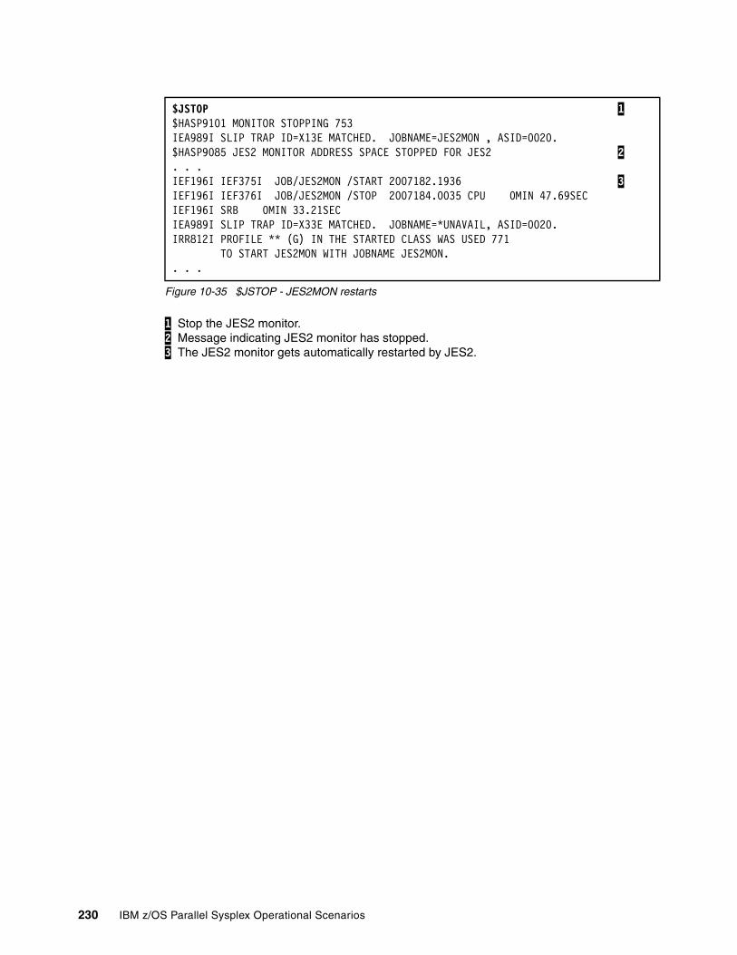
Figure 10-35 $JSTOP - JES2MON restarts
1 Stop the JES2 monitor. 2 Message indicating JES2 monitor has stopped. 3 The JES2 monitor gets automatically restarted by JES2.
$JSTOP 1$HASP9101 MONITOR STOPPING 753 IEA989I SLIP TRAP ID=X13E MATCHED. JOBNAME=JES2MON , ASID=0020. $HASP9085 JES2 MONITOR ADDRESS SPACE STOPPED FOR JES2 2. . . IEF196I IEF375I JOB/JES2MON /START 2007182.1936 3IEF196I IEF376I JOB/JES2MON /STOP 2007184.0035 CPU 0MIN 47.69SEC IEF196I SRB 0MIN 33.21SEC IEA989I SLIP TRAP ID=X33E MATCHED. JOBNAME=*UNAVAIL, ASID=0020. IRR812I PROFILE ** (G) IN THE STARTED CLASS WAS USED 771 TO START JES2MON WITH JOBNAME JES2MON. . . .
230 IBM z/OS Parallel Sysplex Operational Scenarios

Chapter 11. System Display and Search Facility and OPERLOG
This chapter discusses the IBM System Display and Search Facility (SDSF) and OPERLOG. SDSF, which is an optional feature of z/OS, provides you with information that enables you to monitor, manage, and control a z/OS JES2 system.
This chapter discusses how to use SDSF to perform the following tasks:
� View the system log and operlog
� Issue system commands view the result
� Print or save job output and the system log
� Look at the running jobs
� Display JES2 resources
For more information about SDSF, refer to SDSF Operation and Customization, SA22-7670.
11
© Copyright IBM Corp. 2009. All rights reserved. 231
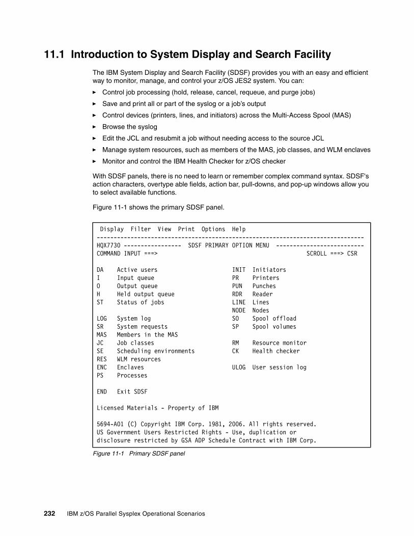
11.1 Introduction to System Display and Search Facility
The IBM System Display and Search Facility (SDSF) provides you with an easy and efficient way to monitor, manage, and control your z/OS JES2 system. You can:
� Control job processing (hold, release, cancel, requeue, and purge jobs)
� Save and print all or part of the syslog or a job’s output
� Control devices (printers, lines, and initiators) across the Multi-Access Spool (MAS)
� Browse the syslog
� Edit the JCL and resubmit a job without needing access to the source JCL
� Manage system resources, such as members of the MAS, job classes, and WLM enclaves
� Monitor and control the IBM Health Checker for z/OS checker
With SDSF panels, there is no need to learn or remember complex command syntax. SDSF's action characters, overtype able fields, action bar, pull-downs, and pop-up windows allow you to select available functions.
Figure 11-1 shows the primary SDSF panel.
Figure 11-1 Primary SDSF panel
Display Filter View Print Options Help-------------------------------------------------------------------------------HQX7730 ----------------- SDSF PRIMARY OPTION MENU --------------------------COMMAND INPUT ===> SCROLL ===> CSR
DA Active users INIT InitiatorsI Input queue PR PrintersO Output queue PUN PunchesH Held output queue RDR Reader ST Status of jobs LINE Lines NODE NodesLOG System log SO Spool offloadSR System requests SP Spool volumesMAS Members in the MASJC Job classes RM Resource monitorSE Scheduling environments CK Health checkerRES WLM resourcesENC Enclaves ULOG User session logPS Processes
END Exit SDSF
Licensed Materials - Property of IBM
5694-A01 (C) Copyright IBM Corp. 1981, 2006. All rights reserved.US Government Users Restricted Rights - Use, duplication ordisclosure restricted by GSA ADP Schedule Contract with IBM Corp.
232 IBM z/OS Parallel Sysplex Operational Scenarios

11.2 Using the LOG command
You can use the LOG command to access either SYSLOG or OPERLOG panels to view the z/OS system log in chronological order.
SYSLOG displays the z/OS system log data sorted by date and time. OPERLOG displays the merged, sysplex-wide system message log managed by the System Logger that is an alternative to the JES2 spool used for the system log. The OPERLOG is also sorted by date and time.
You can see outstanding write-to-operator-with-reply messages (WTORs) at the bottom of both logs.
LOG command options:
� LOG SYSLOG (or LOG S) displays the SYSLOG panel.
� LOG OPER (or LOG O) displays the OPERLOG panel.
� LOG with no parameters displays the default log panel for an individual system.
Use the SET LOG command to specify the default panel that is displayed when you enter the LOG command with no parameters. You can use this command in any SDSF panel (except help and tutorial panels).
SET LOG command options:
� OPERACT (or A) specifies that the OPERLOG panel is displayed if OPERLOG is active on the system you are logged on to; otherwise, the SYSLOG panel is displayed.
� OPERLOG (or O) specifies that the OPERLOG panel is displayed.
� SYSLOG (or S) specifies that the SYSLOG panel is displayed.
� ? displays the current setting for SET LOG.
� SET LOG with no parameters is the same as SET LOG OPERACT.
11.2.1 Example of the SYSLOG panel
If you enter LOG S in a command line, the SYSLOG panel is displayed, as shown in Figure 11-2 on page 234.
Tip: The BOTTOM, TOP, NEXT and PREV commands run faster when preceded by the FINDLIM, LOGLIM and FILTER commands.
� Use FILTER to limit the data displayed on the OPERLOG panel. � Use LOGLIM to limit the amount of OPERLOG data that SDSF will search for records
that meet filter criteria. The limit is between 0 (no limit) and 999 hours.� Use FINDLIM to limit the amount of OPERLOG, SYSLOG and ULOG data that SDSF
will search for records that meet filter criteria. The limit is any number between 1000 and 9999999.
For more information about FILTER, LOGLIM and FINDLIM commands, refer to SDSF Operation and Customization, SA22-7670.
Chapter 11. System Display and Search Facility and OPERLOG 233
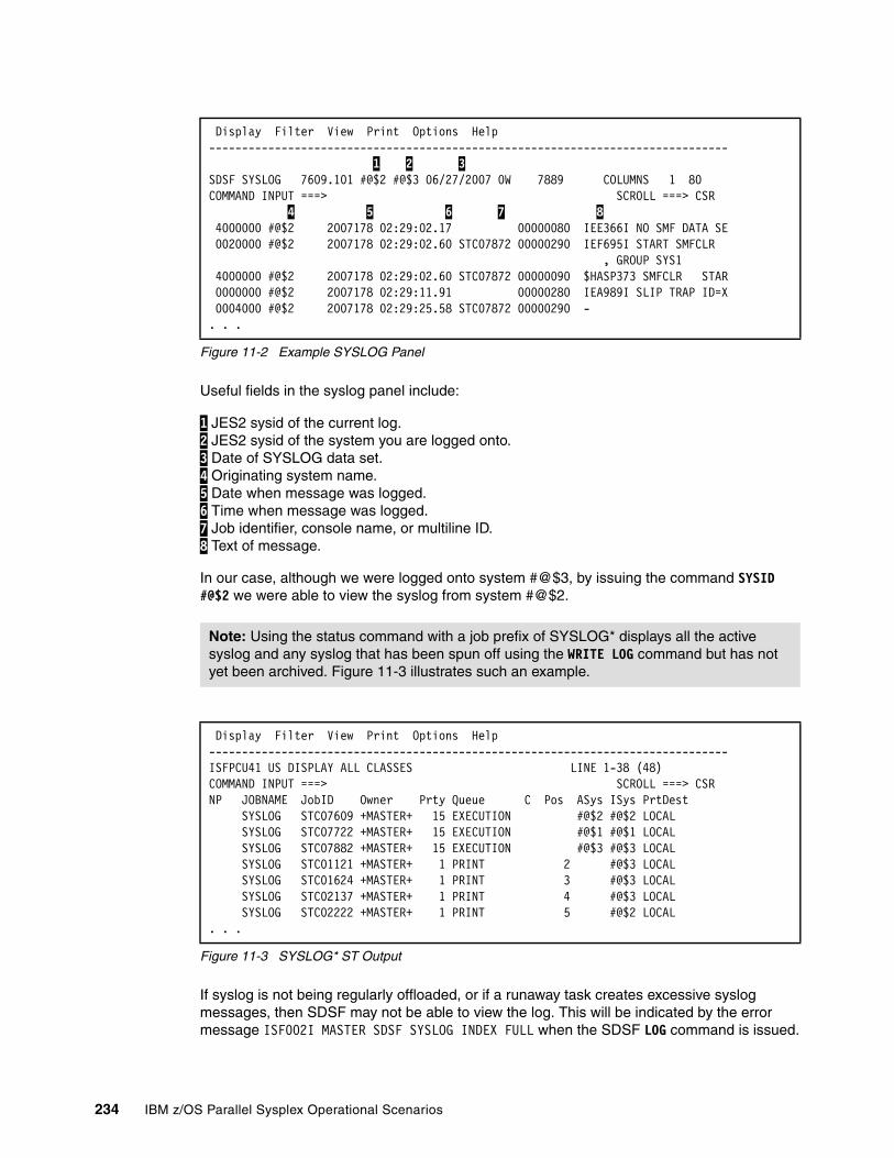
Figure 11-2 Example SYSLOG Panel
Useful fields in the syslog panel include:
1 JES2 sysid of the current log. 2 JES2 sysid of the system you are logged onto. 3 Date of SYSLOG data set. 4 Originating system name. 5 Date when message was logged. 6 Time when message was logged. 7 Job identifier, console name, or multiline ID. 8 Text of message.
In our case, although we were logged onto system #@$3, by issuing the command SYSID #@$2 we were able to view the syslog from system #@$2.
Figure 11-3 SYSLOG* ST Output
If syslog is not being regularly offloaded, or if a runaway task creates excessive syslog messages, then SDSF may not be able to view the log. This will be indicated by the error message ISF002I MASTER SDSF SYSLOG INDEX FULL when the SDSF LOG command is issued.
Display Filter View Print Options Help ------------------------------------------------------------------------------- 1 2 3 SDSF SYSLOG 7609.101 #@$2 #@$3 06/27/2007 0W 7889 COLUMNS 1 80 COMMAND INPUT ===> SCROLL ===> CSR 4 5 6 7 8 4000000 #@$2 2007178 02:29:02.17 00000080 IEE366I NO SMF DATA SE 0020000 #@$2 2007178 02:29:02.60 STC07872 00000290 IEF695I START SMFCLR , GROUP SYS1 4000000 #@$2 2007178 02:29:02.60 STC07872 00000090 $HASP373 SMFCLR STAR 0000000 #@$2 2007178 02:29:11.91 00000280 IEA989I SLIP TRAP ID=X 0004000 #@$2 2007178 02:29:25.58 STC07872 00000290 - . . .
Note: Using the status command with a job prefix of SYSLOG* displays all the active syslog and any syslog that has been spun off using the WRITE LOG command but has not yet been archived. Figure 11-3 illustrates such an example.
Display Filter View Print Options Help -------------------------------------------------------------------------------ISFPCU41 US DISPLAY ALL CLASSES LINE 1-38 (48) COMMAND INPUT ===> SCROLL ===> CSR NP JOBNAME JobID Owner Prty Queue C Pos ASys ISys PrtDest SYSLOG STC07609 +MASTER+ 15 EXECUTION #@$2 #@$2 LOCAL SYSLOG STC07722 +MASTER+ 15 EXECUTION #@$1 #@$1 LOCAL SYSLOG STC07882 +MASTER+ 15 EXECUTION #@$3 #@$3 LOCAL SYSLOG STC01121 +MASTER+ 1 PRINT 2 #@$3 LOCAL SYSLOG STC01624 +MASTER+ 1 PRINT 3 #@$3 LOCAL SYSLOG STC02137 +MASTER+ 1 PRINT 4 #@$3 LOCAL SYSLOG STC02222 +MASTER+ 1 PRINT 5 #@$2 LOCAL . . .
234 IBM z/OS Parallel Sysplex Operational Scenarios
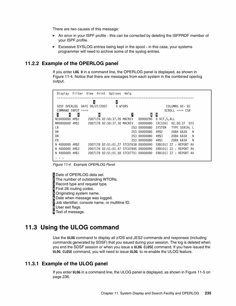
There are two causes of this message:
� An error in your ISPF profile - this can be corrected by deleting the ISFPROF member of your ISPF profile.
� Excessive SYSLOG entries being kept in the spool - in this case, your systems programmer will need to archive some of the syslog entries.
11.2.2 Example of the OPERLOG panel
If you enter LOG O in a command line, the OPERLOG panel is displayed, as shown in Figure 11-4. Notice that there are messages from each system in the combined operlog output.
Figure 11-4 Example OPERLOG Panel
1 Date of OPERLOG data set. 2 The number of outstanding WTORs. 3 Record type and request type. 4 First 28 routing codes. 5 Originating system name. 6 Date when message was logged. 7 Job identifier, console name, or multiline ID. 8 User exit flags. 9 Text of message.
11.3 Using the ULOG command
Use the ULOG command to display all z/OS and JES2 commands and responses (including commands generated by SDSF) that you issued during your session. The log is deleted when you end the SDSF session or when you issue a ULOG CLOSE command. If you have issued the ULOG CLOSE command, you will need to issue ULOG to re-enable the ULOG feature.
11.3.1 Example of the ULOG panel
If you enter ULOG in a command line, the ULOG panel is displayed, as shown in Figure 11-5 on page 236.
Display Filter View Print Options Help ------------------------------------------------------------------------------- 1 2 SDSF OPERLOG DATE 06/27/2007 0 WTORS COLUMNS 02- 81 COMMAND INPUT ===> SCROLL ===> CSR 3 4 5 6 7 8 9 NC0000000 #@$1 2007178 02:50:37.26 MACNIV 00000290 D XCF,S,ALL MR0000000 #@$1 2007178 02:50:37.30 MACNIV 00000080 IXC335I 02.50.37 DISLR 253 00000080 SYSTEM TYPE SERIAL LDR 253 00000080 #@$2 2084 6A3A NDR 253 00000080 #@$3 2084 6A3A NER 253 00000080 #@$1 2084 6A3A NN 4000000 #@$2 2007178 02:51:01.27 STC07638 00000090 ERB101I ZZ : REPORT AVN 4000000 #@$3 2007178 02:51:01.47 STC07695 00000090 ERB101I ZZ : REPORT AVN 4000000 #@$1 2007178 02:51:01.58 STC07751 00000090 ERB101I ZZ : REPORT AV. . .
Chapter 11. System Display and Search Facility and OPERLOG 235

Figure 11-5 Example ULOG
1 Extended console name. This will be NOT ACTIVE if the console was turned off with the ULOG CLOSE command, or you are not authorized to use it. 2 System name on which the command was issued, or from which the response originated. 3 Date when the message was logged. 4 Job ID applying to the message, if available. 5 Command text or message response. If it is echoed by SDSF, it is preceded by a hyphen (-).
Use the PRINT command to save the ULOG data. You can route it to a printer or save it in a data set. You will need to save the ULOG data before exiting SDSF. The PRINT command is described in 11.5, “Printing and saving output in SDSF” on page 239.
The ULOG command creates an EMCS console, and the default name for the console is your user ID. Each EMCS console in a sysplex requires a unique name. Thus, if you attempt to open a second ULOG screen, for example by having two SDSF sessions within a single ISPF session you receive the message ISF031I, as seen in 2 Figure 11-6.
Figure 11-6 Second ULOG session started
When this happens, SDSF will share an EMCS console 1. However, responses to commands are always sent to the first SDSF console, not to the second (shared) console.
Figure 11-7 on page 237 shows a command issued. However, the output is displayed in the primary SDSF ULOG panel, as seen in Figure 11-8 on page 237.
Display Filter View Print Options Help ------------------------------------------------------------------------------- 1 SDSF ULOG CONSOLE COTTRELC LINE 0 COLUMNS 02- 81 COMMAND INPUT ===> SCROLL ===> CSR ********************************* TOP OF DATA ********************************** 2 3 4 5 #@$2 2007178 02:16:03.95 ISF031I CONSOLE COTTREL ACTIVATED #@$2 2007178 02:16:09.90 -D XCF,STR #@$2 2007178 02:16:10.13 IXC359I 02.16.09 DISPLAY XCF 650 STRNAME ALLOCATION TIME CIC_DFHLOG_001 06/27/2007 01:08:52 CIC_DFHSHUNT_001 06/27/2007 01:08:53 CIC_GENERAL_001 -- -- . . .
Display Filter View Print Options Help ------------------------------------------------------------------------------- 1 SDSF ULOG CONSOLE COTTRELC (SHARED) LINE 0 COLUMNS 42- 121 COMMAND INPUT ===> SCROLL ===> CSR ********************************* TOP OF DATA ********************************** ISF031I CONSOLE COTTRELC ACTIVATED (SHARED) 2 ******************************** BOTTOM OF DATA ********************************
236 IBM z/OS Parallel Sysplex Operational Scenarios
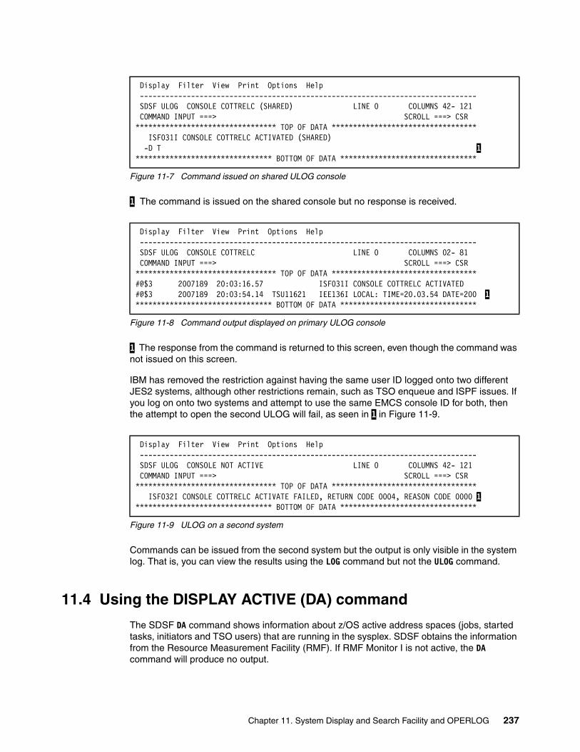
Figure 11-7 Command issued on shared ULOG console
1 The command is issued on the shared console but no response is received.
Figure 11-8 Command output displayed on primary ULOG console
1 The response from the command is returned to this screen, even though the command was not issued on this screen.
IBM has removed the restriction against having the same user ID logged onto two different JES2 systems, although other restrictions remain, such as TSO enqueue and ISPF issues. If you log on onto two systems and attempt to use the same EMCS console ID for both, then the attempt to open the second ULOG will fail, as seen in 1 in Figure 11-9.
Figure 11-9 ULOG on a second system
Commands can be issued from the second system but the output is only visible in the system log. That is, you can view the results using the LOG command but not the ULOG command.
11.4 Using the DISPLAY ACTIVE (DA) command
The SDSF DA command shows information about z/OS active address spaces (jobs, started tasks, initiators and TSO users) that are running in the sysplex. SDSF obtains the information from the Resource Measurement Facility (RMF). If RMF Monitor I is not active, the DA command will produce no output.
Display Filter View Print Options Help ------------------------------------------------------------------------------- SDSF ULOG CONSOLE COTTRELC (SHARED) LINE 0 COLUMNS 42- 121 COMMAND INPUT ===> SCROLL ===> CSR ********************************* TOP OF DATA ********************************** ISF031I CONSOLE COTTRELC ACTIVATED (SHARED) -D T 1******************************** BOTTOM OF DATA ********************************
Display Filter View Print Options Help ------------------------------------------------------------------------------- SDSF ULOG CONSOLE COTTRELC LINE 0 COLUMNS 02- 81 COMMAND INPUT ===> SCROLL ===> CSR ********************************* TOP OF DATA ********************************** #@$3 2007189 20:03:16.57 ISF031I CONSOLE COTTRELC ACTIVATED #@$3 2007189 20:03:54.14 TSU11621 IEE136I LOCAL: TIME=20.03.54 DATE=200 1******************************** BOTTOM OF DATA ********************************
Display Filter View Print Options Help ------------------------------------------------------------------------------- SDSF ULOG CONSOLE NOT ACTIVE LINE 0 COLUMNS 42- 121 COMMAND INPUT ===> SCROLL ===> CSR ********************************* TOP OF DATA ********************************** ISF032I CONSOLE COTTRELC ACTIVATE FAILED, RETURN CODE 0004, REASON CODE 0000 1******************************** BOTTOM OF DATA ********************************
Chapter 11. System Display and Search Facility and OPERLOG 237
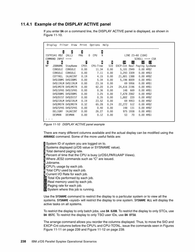
11.4.1 Example of the DISPLAY ACTIVE panel
If you enter DA on a command line, the DISPLAY ACTIVE panel is displayed, as shown in Figure 11-10.
Figure 11-10 DISPLAY ACTIVE panel example
There are many different columns available and the actual display can be modified using the ARRANGE command. Some of the more useful fields are:
1 System ID of system you are logged on to. 2 Systems displayed (z/OS value or SYSNAME value). 3 Total demand paging rate. 4 Percent of time that the CPU is busy (z/OS/LPAR/zAAP Views). 5 Where JES2 commands such as “C” are issued. 6 Jobname. 7 CPU% usage by each job. 8 Total CPU used by each job. 9 Current I/O Rate for each job. 10 Total IOs performed by each job. 11 Real memory used by each job. 12 Paging rate for each job. 13 System where this job is running.
Use the SYSNAME command to restrict the display to a particular system or to view all the systems. SYSNAME <sysid> will restrict the display to one system. SYSNAME ALL will display the active tasks on all systems.
To restrict the display to only batch jobs, use DA OJOB. To restrict the display to only STCs, use DA OSTC. To restrict the display to only TSO user IDs, use DA OTSU.
The arrange command allows you reorder the columns displayed. Thus, to move the SIO and EXCP-Cnt columns before the CPU% and CPU-TOTAL, issue the commands seen in Figures Figure 11-11 on page 239 and Figure 11-12 on page 239.
Display Filter View Print Options Help ------------------------------------------------------------------------------- 1 2 3 4 ISFPCU41 @$2 (ALL) PAG 0 CPU 9 LINE 23-60 (184) COMMAND INPUT ===> SCROLL ===> CSR 5 6 7 8 9 10 11 12 13 NP JOBNAME StepName CPU% CPU-Time SIO EXCP-Cnt Real Paging SysName CONSOLE CONSOLE 0.00 11.34 0.00 5,101 2949 0.00 #@$2 CONSOLE CONSOLE 0.00 7.11 0.00 3,293 3309 0.00 #@$3 COTTREL IKJACCNT 0.19 4.15 0.00 21,801 1388 0.00 #@$2 D#$1DBM1 D#$1DBM1 0.00 5.34 0.00 5,196 8009 0.00 #@$1 D#$1IRLM D#$1IRLM 0.00 23.16 0.00 69 5956 0.00 #@$1 D#$1MSTR D#$1MSTR 0.00 62.20 0.24 24,616 2196 0.00 #@$1 D#$1SPAS D#$1SPAS 0.00 0.36 0.00 148 669 0.00 #@$1 D#$2DBM1 D#$2DBM1 0.00 3.25 0.00 7,678 2062 0.00 #@$2 D#$2DIST D#$2DIST 0.00 0.35 0.00 1,802 220 0.00 #@$2 D#$2IRLM D#$2IRLM 0.19 23.52 0.00 69 4953 0.00 #@$2 D#$2MSTR D#$2MSTR 0.32 65.28 0.24 22,272 512 0.00 #@$2 D#$2SPAS D#$2SPAS 0.00 0.40 0.00 148 131 0.00 #@$2 DELIGNY IKJACCNT 0.00 26.27 0.00 975 1938 0.00 #@$1 DEVMAN DEVMAN 0.00 0.12 0.00 53 70 0.00 #@$1 . . .
238 IBM z/OS Parallel Sysplex Operational Scenarios
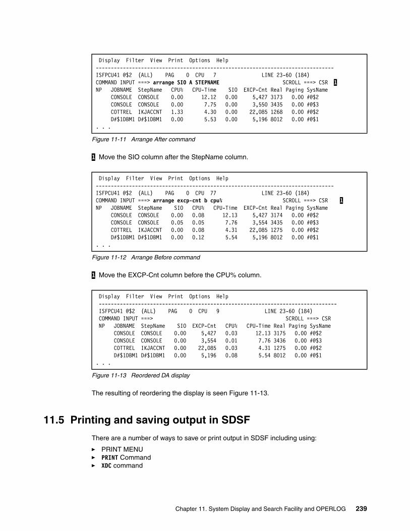
Figure 11-11 Arrange After command
1 Move the SIO column after the StepName column.
Figure 11-12 Arrange Before command
1 Move the EXCP-Cnt column before the CPU% column.
Figure 11-13 Reordered DA display
The resulting of reordering the display is seen Figure 11-13.
11.5 Printing and saving output in SDSF
There are a number of ways to save or print output in SDSF including using:
� PRINT MENU� PRINT Command� XDC command
Display Filter View Print Options Help -------------------------------------------------------------------------------ISFPCU41 @$2 (ALL) PAG 0 CPU 7 LINE 23-60 (184) COMMAND INPUT ===> arrange SIO A STEPNAME SCROLL ===> CSR 1NP JOBNAME StepName CPU% CPU-Time SIO EXCP-Cnt Real Paging SysName CONSOLE CONSOLE 0.00 12.12 0.00 5,427 3173 0.00 #@$2 CONSOLE CONSOLE 0.00 7.75 0.00 3,550 3435 0.00 #@$3 COTTREL IKJACCNT 1.33 4.30 0.00 22,085 1268 0.00 #@$2 D#$1DBM1 D#$1DBM1 0.00 5.53 0.00 5,196 8012 0.00 #@$1 . . .
Display Filter View Print Options Help -------------------------------------------------------------------------------ISFPCU41 @$2 (ALL) PAG 0 CPU 77 LINE 23-60 (184) COMMAND INPUT ===> arrange excp-cnt b cpu% SCROLL ===> CSR 1NP JOBNAME StepName SIO CPU% CPU-Time EXCP-Cnt Real Paging SysName CONSOLE CONSOLE 0.00 0.08 12.13 5,427 3174 0.00 #@$2 CONSOLE CONSOLE 0.05 0.05 7.76 3,554 3435 0.00 #@$3 COTTREL IKJACCNT 0.00 0.08 4.31 22,085 1275 0.00 #@$2 D#$1DBM1 D#$1DBM1 0.00 0.12 5.54 5,196 8012 0.00 #@$1 . . .
Display Filter View Print Options Help ------------------------------------------------------------------------------- ISFPCU41 @$2 (ALL) PAG 0 CPU 9 LINE 23-60 (184) COMMAND INPUT ===> SCROLL ===> CSR NP JOBNAME StepName SIO EXCP-Cnt CPU% CPU-Time Real Paging SysName CONSOLE CONSOLE 0.00 5,427 0.03 12.13 3175 0.00 #@$2 CONSOLE CONSOLE 0.00 3,554 0.01 7.76 3436 0.00 #@$3 COTTREL IKJACCNT 0.00 22,085 0.03 4.31 1275 0.00 #@$2 D#$1DBM1 D#$1DBM1 0.00 5,196 0.08 5.54 8012 0.00 #@$1 . . .
Chapter 11. System Display and Search Facility and OPERLOG 239
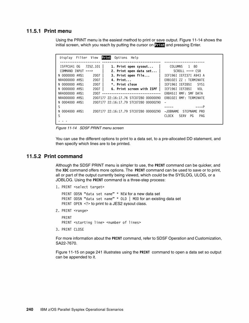
11.5.1 Print menu
Using the PRINT menu is the easiest method to print or save output. Figure 11-14 shows the initial screen, which you reach by putting the cursor on Print and pressing Enter.
Figure 11-14 SDSF PRINT menu screen
You can use the different options to print to a data set, to a pre-allocated DD statement, and then specify which lines are to be printed.
11.5.2 Print command
Although the SDSF PRINT menu is simpler to use, the PRINT command can be quicker, and the XDC command offers more options. The PRINT command can be used to save or to print, all or part of the output currently being viewed, which could be the SYSLOG, ULOG, or a JOBLOG. Using the PRINT command is a three-step process:
1. PRINT <select target>
PRINT ODSN “data set name” * NEW for a new data setPRINT ODSN “data set name” * OLD | MOD for an existing data setPRINT OPEN <?> to print to a JES2 sysout class.
2. PRINT <range>
PRINTPRINT <starting line> <number of lines>
3. PRINT CLOSE
For more information about the PRINT command, refer to SDSF Operation and Customization, SA22-7670.
Figure 11-15 on page 241 illustrates using the PRINT command to open a data set so output can be appended to it.
Display Filter View Print Options Help ---------------------- -------------------------------- ---------------------- ISFPCU41 OG 7252.101 | 1. Print open sysout... | COLUMNS 1 80 COMMAND INPUT ===> | 2. Print open data set... | SCROLL ===> CSR N 0000000 #@$1 2007 | 3. Print open file... | IEF196I IEF237I A943 ANR4000000 #@$1 2007 | 4. Print... | ERB102I ZZ : TERMINATEN 0000000 #@$1 2007 | *. Print close | IEF196I IEF285I SYS1N 0000000 #@$1 2007 | 6. Print screen with ISPF | IEF196I IEF285I VOL NR4000000 #@$1 2007 -------------------------------- ERB451I RMF: SMF DATA NR4000000 #@$1 2007177 22:16:17.76 STC07280 00000090 ERB102I RMF: TERMINATEN 0004000 #@$1 2007177 22:16:17.79 STC07280 00000290 - S ----- ----PN 0004000 #@$1 2007177 22:16:17.79 STC07280 00000290 -JOBNAME STEPNAME PROS CLOCK SERV PG PAG. . .
240 IBM z/OS Parallel Sysplex Operational Scenarios
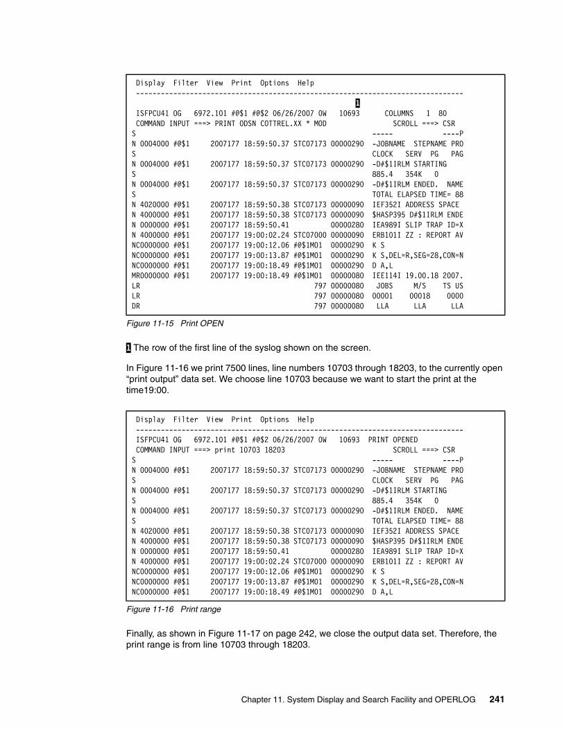
Figure 11-15 Print OPEN
1 The row of the first line of the syslog shown on the screen.
In Figure 11-16 we print 7500 lines, line numbers 10703 through 18203, to the currently open “print output” data set. We choose line 10703 because we want to start the print at the time19:00.
Figure 11-16 Print range
Finally, as shown in Figure 11-17 on page 242, we close the output data set. Therefore, the print range is from line 10703 through 18203.
Display Filter View Print Options Help ------------------------------------------------------------------------------- 1 ISFPCU41 OG 6972.101 #@$1 #@$2 06/26/2007 0W 10693 COLUMNS 1 80 COMMAND INPUT ===> PRINT ODSN COTTREL.XX * MOD SCROLL ===> CSR S ----- ----PN 0004000 #@$1 2007177 18:59:50.37 STC07173 00000290 -JOBNAME STEPNAME PROS CLOCK SERV PG PAGN 0004000 #@$1 2007177 18:59:50.37 STC07173 00000290 -D#$1IRLM STARTING S 885.4 354K 0 N 0004000 #@$1 2007177 18:59:50.37 STC07173 00000290 -D#$1IRLM ENDED. NAMES TOTAL ELAPSED TIME= 88N 4020000 #@$1 2007177 18:59:50.38 STC07173 00000090 IEF352I ADDRESS SPACE N 4000000 #@$1 2007177 18:59:50.38 STC07173 00000090 $HASP395 D#$1IRLM ENDEN 0000000 #@$1 2007177 18:59:50.41 00000280 IEA989I SLIP TRAP ID=XN 4000000 #@$1 2007177 19:00:02.24 STC07000 00000090 ERB101I ZZ : REPORT AVNC0000000 #@$1 2007177 19:00:12.06 #@$1M01 00000290 K S NC0000000 #@$1 2007177 19:00:13.87 #@$1M01 00000290 K S,DEL=R,SEG=28,CON=NNC0000000 #@$1 2007177 19:00:18.49 #@$1M01 00000290 D A,L MR0000000 #@$1 2007177 19:00:18.49 #@$1M01 00000080 IEE114I 19.00.18 2007.LR 797 00000080 JOBS M/S TS USLR 797 00000080 00001 00018 0000DR 797 00000080 LLA LLA LLA
Display Filter View Print Options Help ------------------------------------------------------------------------------- ISFPCU41 OG 6972.101 #@$1 #@$2 06/26/2007 0W 10693 PRINT OPENED COMMAND INPUT ===> print 10703 18203 SCROLL ===> CSR S ----- ----PN 0004000 #@$1 2007177 18:59:50.37 STC07173 00000290 -JOBNAME STEPNAME PROS CLOCK SERV PG PAGN 0004000 #@$1 2007177 18:59:50.37 STC07173 00000290 -D#$1IRLM STARTING S 885.4 354K 0 N 0004000 #@$1 2007177 18:59:50.37 STC07173 00000290 -D#$1IRLM ENDED. NAMES TOTAL ELAPSED TIME= 88N 4020000 #@$1 2007177 18:59:50.38 STC07173 00000090 IEF352I ADDRESS SPACE N 4000000 #@$1 2007177 18:59:50.38 STC07173 00000090 $HASP395 D#$1IRLM ENDEN 0000000 #@$1 2007177 18:59:50.41 00000280 IEA989I SLIP TRAP ID=XN 4000000 #@$1 2007177 19:00:02.24 STC07000 00000090 ERB101I ZZ : REPORT AVNC0000000 #@$1 2007177 19:00:12.06 #@$1M01 00000290 K S NC0000000 #@$1 2007177 19:00:13.87 #@$1M01 00000290 K S,DEL=R,SEG=28,CON=NNC0000000 #@$1 2007177 19:00:18.49 #@$1M01 00000290 D A,L
Chapter 11. System Display and Search Facility and OPERLOG 241
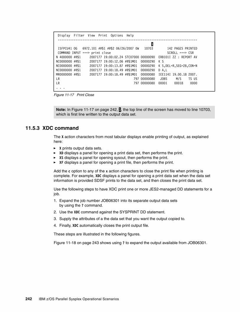
Figure 11-17 Print Close
11.5.3 XDC command
The X action characters from most tabular displays enable printing of output, as explained here:
� X prints output data sets.� XD displays a panel for opening a print data set, then performs the print.� XS displays a panel for opening sysout, then performs the print.� XF displays a panel for opening a print file, then performs the print.
Add the c option to any of the x action characters to close the print file when printing is complete. For example, XDC displays a panel for opening a print data set when the data set information is provided SDSF prints to the data set, and then closes the print data set.
Use the following steps to have XDC print one or more JES2-managed DD statements for a job.
1. Expand the job number JOB06301 into its separate output data setsby using the ? command.
2. Use the XDC command against the SYSPRINT DD statement.
3. Supply the attributes of a the data set that you want the output copied to.
4. Finally, XDC automatically closes the print output file.
These steps are illustrated in the following figures.
Figure 11-18 on page 243 shows using ? to expand the output available from JOB06301.
Display Filter View Print Options Help ------------------------------------------------------------------------------- 1 ISFPCU41 OG 6972.101 #@$1 #@$2 06/26/2007 0W 10703 142 PAGES PRINTED COMMAND INPUT ===> print close SCROLL ===> CSR N 4000000 #@$1 2007177 19:00:02.24 STC07000 00000090 ERB101I ZZ : REPORT AVNC0000000 #@$1 2007177 19:00:12.06 #@$1M01 00000290 K S NC0000000 #@$1 2007177 19:00:13.87 #@$1M01 00000290 K S,DEL=R,SEG=28,CON=NNC0000000 #@$1 2007177 19:00:18.49 #@$1M01 00000290 D A,L MR0000000 #@$1 2007177 19:00:18.49 #@$1M01 00000080 IEE114I 19.00.18 2007.LR 797 00000080 JOBS M/S TS USLR 797 00000080 00001 00018 0000. . .
Note: In Figure 11-17 on page 242, 1, the top line of the screen has moved to line 10703, which is first line written to the output data set.
242 IBM z/OS Parallel Sysplex Operational Scenarios
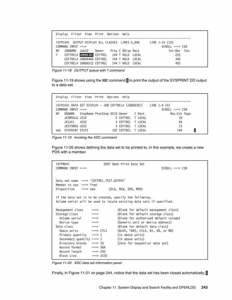
Figure 11-18 OUTPUT queue with ? command
Figure 11-19 shows using the XDC command 1 to print the output of the SYSPRINT DD output to a data set.
Figure 11-19 Invoking the XDC command
Figure 11-20 shows defining the data set to be printed to. In this example, we create a new PDS with a member.
Figure 11-20 XDC data set information panel
Finally, in Figure 11-21 on page 244, notice that the data set has been closed automatically, 1
Display Filter View Print Options Help ------------------------------------------------------------------------------- ISFPCU41 OUTPUT DISPLAY ALL CLASSES LINES 5,906 LINE 1-15 (15) COMMAND INPUT ===> SCROLL ===> CSR NP JOBNAME JobID Owner Prty C ODisp Dest Tot-Rec Tot- ? COTTREL# JOB06301 COTTREL 144 T HOLD LOCAL 225 COTTREL# JOB06466 COTTREL 144 T HOLD LOCAL 340 COTTREL# JOB06512 COTTREL 144 T HOLD LOCAL 403
Display Filter View Print Options Help ------------------------------------------------------------------------------- ISFPCU41 DATA SET DISPLAY - JOB COTTREL# (JOB06301) LINE 1-4 (4) COMMAND INPUT ===> SCROLL ===> CSR NP DDNAME StepName ProcStep DSID Owner C Dest Rec-Cnt Page JESMSGLG JES2 2 COTTREL T LOCAL 18 JESJCL JES2 3 COTTREL T LOCAL 45 JESYSMSG JES2 4 COTTREL T LOCAL 13 xdc SYSPRINT STEP1 102 COTTREL T LOCAL 149 1
ISFPNO41 SDSF Open Print Data Set COMMAND INPUT ===> SCROLL ===> CSR Data set name ===> 'COTTREL.TEST.OUTPUT' Member to use ===> fred Disposition ===> new (OLD, NEW, SHR, MOD) If the data set is to be created, specify the following. Volume serial will be used to locate existing data sets if specified. Management class ===> (Blank for default management class) Storage class ===> (Blank for default storage class) Volume serial ===> (Blank for authorized default volume) Device type ===> (Generic unit or device address) Data class ===> (Blank for default data class) Space units ===> CYLS (BLKS, TRKS, CYLS, BY, KB, or MB) Primary quantity ===> 1 (In above units) Secondary quantity ===> 1 (In above units) Directory blocks ===> 10 (Zero for sequential data set) Record format ===> VBA Record length ===> 240 Block size ===> 3120
Chapter 11. System Display and Search Facility and OPERLOG 243
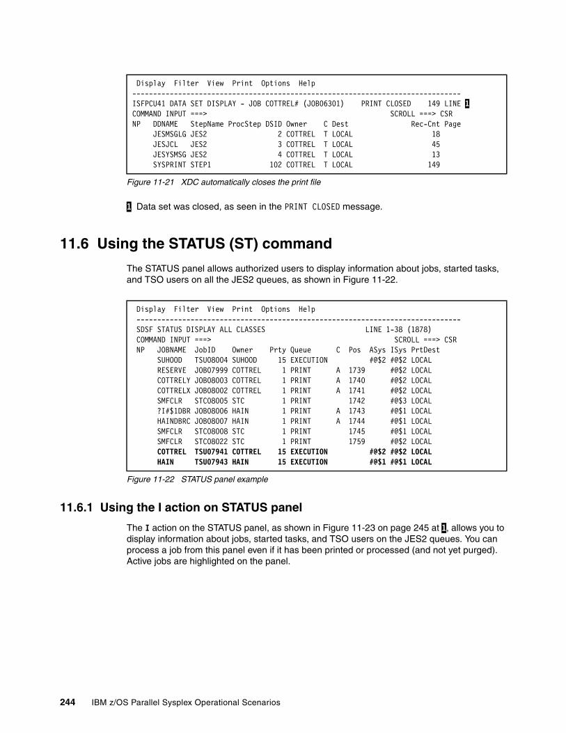
Figure 11-21 XDC automatically closes the print file
1 Data set was closed, as seen in the PRINT CLOSED message.
11.6 Using the STATUS (ST) command
The STATUS panel allows authorized users to display information about jobs, started tasks, and TSO users on all the JES2 queues, as shown in Figure 11-22.
Figure 11-22 STATUS panel example
11.6.1 Using the I action on STATUS panel
The I action on the STATUS panel, as shown in Figure 11-23 on page 245 at 1, allows you to display information about jobs, started tasks, and TSO users on the JES2 queues. You can process a job from this panel even if it has been printed or processed (and not yet purged). Active jobs are highlighted on the panel.
Display Filter View Print Options Help -------------------------------------------------------------------------------ISFPCU41 DATA SET DISPLAY - JOB COTTREL# (JOB06301) PRINT CLOSED 149 LINE 1COMMAND INPUT ===> SCROLL ===> CSR NP DDNAME StepName ProcStep DSID Owner C Dest Rec-Cnt Page JESMSGLG JES2 2 COTTREL T LOCAL 18 JESJCL JES2 3 COTTREL T LOCAL 45 JESYSMSG JES2 4 COTTREL T LOCAL 13 SYSPRINT STEP1 102 COTTREL T LOCAL 149
Display Filter View Print Options Help ------------------------------------------------------------------------------ SDSF STATUS DISPLAY ALL CLASSES LINE 1-38 (1878) COMMAND INPUT ===> SCROLL ===> CSR NP JOBNAME JobID Owner Prty Queue C Pos ASys ISys PrtDest SUHOOD TSU08004 SUHOOD 15 EXECUTION #@$2 #@$2 LOCAL RESERVE JOB07999 COTTREL 1 PRINT A 1739 #@$2 LOCAL COTTRELY JOB08003 COTTREL 1 PRINT A 1740 #@$2 LOCAL COTTRELX JOB08002 COTTREL 1 PRINT A 1741 #@$2 LOCAL SMFCLR STC08005 STC 1 PRINT 1742 #@$3 LOCAL ?I#$1DBR JOB08006 HAIN 1 PRINT A 1743 #@$1 LOCAL HAINDBRC JOB08007 HAIN 1 PRINT A 1744 #@$1 LOCAL SMFCLR STC08008 STC 1 PRINT 1745 #@$1 LOCAL SMFCLR STC08022 STC 1 PRINT 1759 #@$2 LOCAL COTTREL TSU07941 COTTREL 15 EXECUTION #@$2 #@$2 LOCAL HAIN TSU07943 HAIN 15 EXECUTION #@$1 #@$1 LOCAL
244 IBM z/OS Parallel Sysplex Operational Scenarios
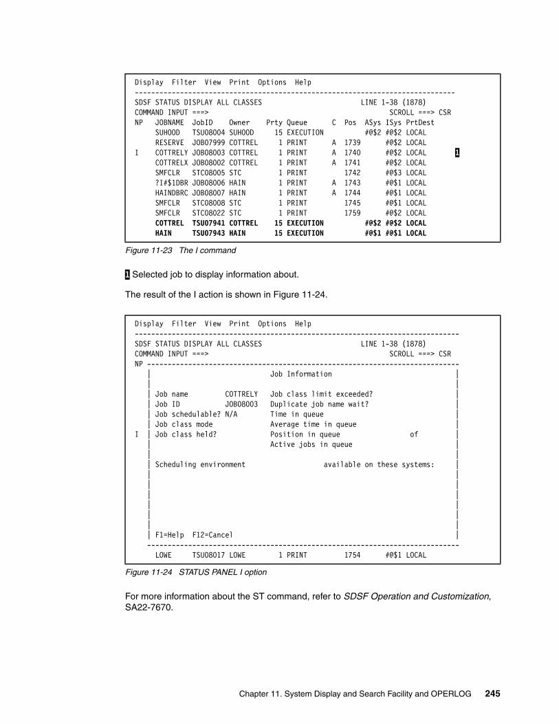
Figure 11-23 The I command
1 Selected job to display information about.
The result of the I action is shown in Figure 11-24.
Figure 11-24 STATUS PANEL I option
For more information about the ST command, refer to SDSF Operation and Customization, SA22-7670.
Display Filter View Print Options Help ------------------------------------------------------------------------------ SDSF STATUS DISPLAY ALL CLASSES LINE 1-38 (1878) COMMAND INPUT ===> SCROLL ===> CSR NP JOBNAME JobID Owner Prty Queue C Pos ASys ISys PrtDest SUHOOD TSU08004 SUHOOD 15 EXECUTION #@$2 #@$2 LOCAL RESERVE JOB07999 COTTREL 1 PRINT A 1739 #@$2 LOCAL I COTTRELY JOB08003 COTTREL 1 PRINT A 1740 #@$2 LOCAL 1 COTTRELX JOB08002 COTTREL 1 PRINT A 1741 #@$2 LOCAL SMFCLR STC08005 STC 1 PRINT 1742 #@$3 LOCAL ?I#$1DBR JOB08006 HAIN 1 PRINT A 1743 #@$1 LOCAL HAINDBRC JOB08007 HAIN 1 PRINT A 1744 #@$1 LOCAL SMFCLR STC08008 STC 1 PRINT 1745 #@$1 LOCAL SMFCLR STC08022 STC 1 PRINT 1759 #@$2 LOCAL COTTREL TSU07941 COTTREL 15 EXECUTION #@$2 #@$2 LOCAL HAIN TSU07943 HAIN 15 EXECUTION #@$1 #@$1 LOCAL
Display Filter View Print Options Help ------------------------------------------------------------------------------- SDSF STATUS DISPLAY ALL CLASSES LINE 1-38 (1878) COMMAND INPUT ===> SCROLL ===> CSR NP ---------------------------------------------------------------------------- | Job Information | | | | Job name COTTRELY Job class limit exceeded? | | Job ID JOB08003 Duplicate job name wait? | | Job schedulable? N/A Time in queue | | Job class mode Average time in queue | I | Job class held? Position in queue of | | Active jobs in queue | | | | Scheduling environment available on these systems: | | | | | | | | | | | | | | F1=Help F12=Cancel | ---------------------------------------------------------------------------- LOWE TSU08017 LOWE 1 PRINT 1754 #@$1 LOCAL
Chapter 11. System Display and Search Facility and OPERLOG 245

11.7 Resource monitor (RM) command
SDSF interacts with JES2. It can display the input, output, and held queues. If authorized, the SDSF user can display and modify from the RM panel many of these JES2 resources. The result of issuing the RM command is seen in Figure 11-25. The values displayed are normally configured by your site’s system programmer. For an explanation of these values, refer to the SDSF help panel or z/OS JES2 Initialization and Tuning Reference, SA22-7533.
Figure 11-25 SDSF RM Panel
11.8 SDSF and MAS
JES2 supports a multi-access spool (MAS) configuration, that is, multiple systems sharing JES2 input, job, and output queues. The JES2 spool is where the job input and output queues are stored. A copy of the JES2 queues and other status information (for example, spool space allocation maps) is written to the checkpoint data set to facilitate a warm start.
SDSF, which is an optional feature of z/OS, can monitor, manage, and control your z/OS JES2 system. Although there are many benefits to having a MAS to match the scope of the sysplex, it is not required. There are some situations in which it is beneficial to have the JES2 MAS smaller than the sysplex. As seen in Figure 11-26 on page 247, it is possible to have many JESPLEXes within a single sysplex.
SDSF only works within a single MAS. Thus, if system #@$1 has a separate JES2 MAS from systems #@$2 and #@$3, then it would not be possible to view the JES2 environment of system #@$1 while using SDSF on #@$2 or #@$3. The systems that share a MAS are commonly called a JESPLEX.
Figure 11-26 on page 247 shows a single sysplex, with nine z/OS systems. JESPLEX1 has four z/OS images, JESPLEX2 has three z/OS images. Systems Y and Z each are
Display Filter View Print Options Help -------------------------------------------------------------------------------SDSF RESOURCE MONITOR DISPLAY #@$3 LINE 1-17 (17) COMMAND INPUT ===> SCROLL ===> CSR PREFIX=CICS* DEST=(ALL) OWNER=* SYSNAME=* NP RESOURCE SysId Status Limit InUse InUse% Warn% IntAvg IntHigh IntLow BERT #@$3 65620 322 0.49 80 322 322 322 BSCB #@$3 0 0 0.00 0 0 0 2B BUFX #@$3 89 0 0.00 80 0 0 0 CKVR #@$3 2 0 0.00 80 0 0 0 CMBS #@$3 201 0 0.00 80 0 0 0 CMDS #@$3 200 0 0.00 80 0 0 0 ICES #@$3 33 0 0.00 80 0 0 0 JNUM #@$3 32760 1342 4.09 80 1342 1342 1342 JOES #@$3 20000 1506 7.53 80 1506 1506 1506 JQES #@$3 32760 1342 4.09 80 1342 1342 1342 LBUF #@$3 23 0 0.00 80 0 0 0 NHBS #@$3 53 0 0.00 80 0 0 0 SMFB #@$3 52 0 0.00 80 0 0 0 TBUF #@$3 104 0 0.00 0 0 0 0 TGS #@$3 9911 7853 79.23 80 7853 7853 7853 TTAB #@$3 3 0 0.00 80 0 0 0 VTMB #@$3 10 0 0.00 80 0 0 0
246 IBM z/OS Parallel Sysplex Operational Scenarios
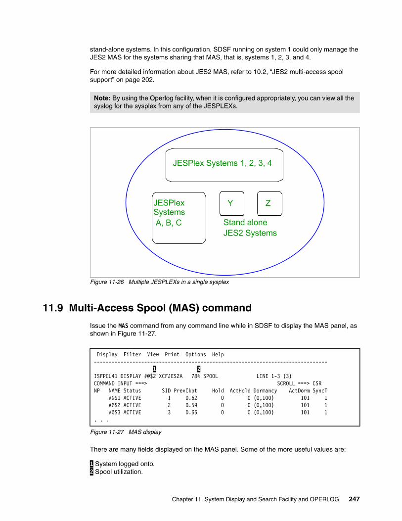
stand-alone systems. In this configuration, SDSF running on system 1 could only manage the JES2 MAS for the systems sharing that MAS, that is, systems 1, 2, 3, and 4.
For more detailed information about JES2 MAS, refer to 10.2, “JES2 multi-access spool support” on page 202.
Figure 11-26 Multiple JESPLEXs in a single sysplex
11.9 Multi-Access Spool (MAS) command
Issue the MAS command from any command line while in SDSF to display the MAS panel, as shown in Figure 11-27.
Figure 11-27 MAS display
There are many fields displayed on the MAS panel. Some of the more useful values are:
1 System logged onto. 2 Spool utilization.
Note: By using the Operlog facility, when it is configured appropriately, you can view all the syslog for the sysplex from any of the JESPLEXs.
JESPlex Systems 1, 2, 3, 4
JESPlex Systems A, B, C Stand alone
JES2 Systems
Y Z
Display Filter View Print Options Help ------------------------------------------------------------------------------- 1 2 ISFPCU41 DISPLAY #@$2 XCFJES2A 78% SPOOL LINE 1-3 (3) COMMAND INPUT ===> SCROLL ===> CSR NP NAME Status SID PrevCkpt Hold ActHold Dormancy ActDorm SyncT #@$1 ACTIVE 1 0.62 0 0 (0,100) 101 1 #@$2 ACTIVE 2 0.59 0 0 (0,100) 101 1 #@$3 ACTIVE 3 0.65 0 0 (0,100) 101 1. . .
Chapter 11. System Display and Search Facility and OPERLOG 247
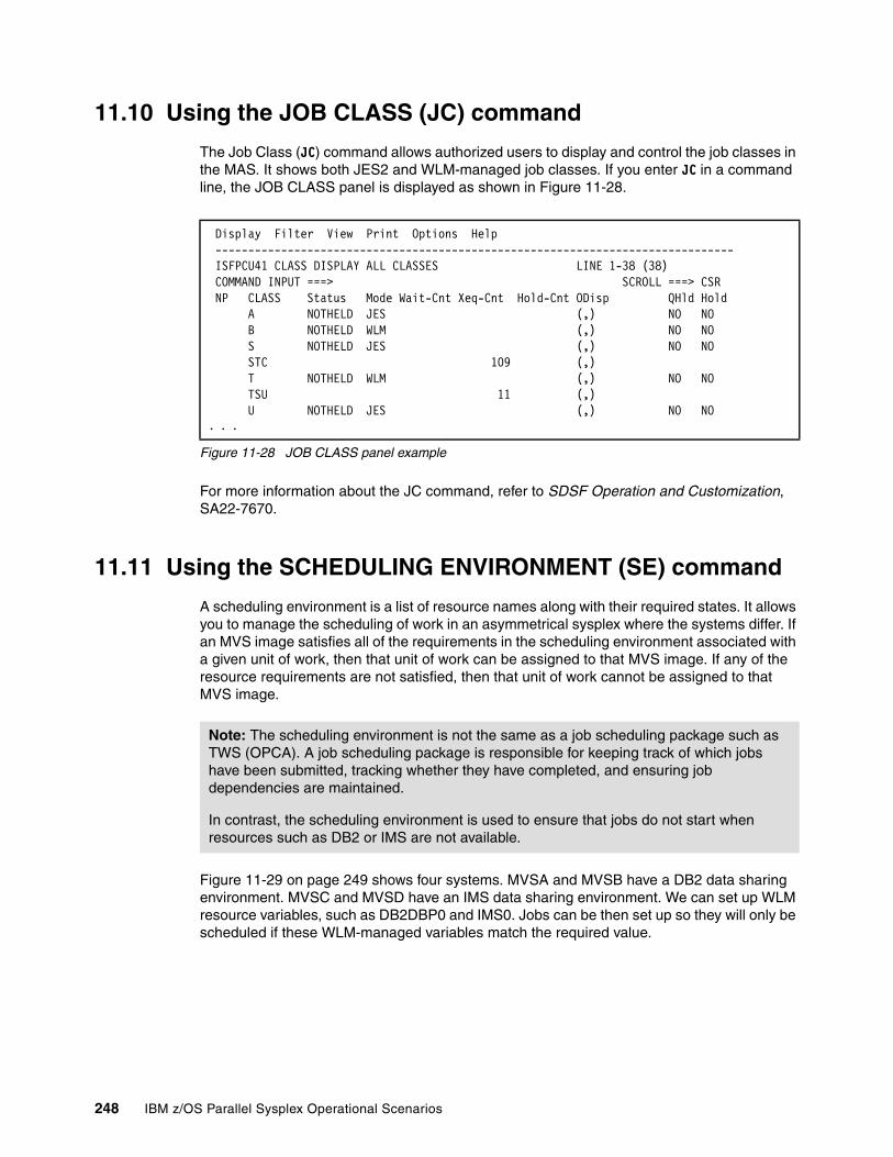
11.10 Using the JOB CLASS (JC) command
The Job Class (JC) command allows authorized users to display and control the job classes in the MAS. It shows both JES2 and WLM-managed job classes. If you enter JC in a command line, the JOB CLASS panel is displayed as shown in Figure 11-28.
Figure 11-28 JOB CLASS panel example
For more information about the JC command, refer to SDSF Operation and Customization, SA22-7670.
11.11 Using the SCHEDULING ENVIRONMENT (SE) command
A scheduling environment is a list of resource names along with their required states. It allows you to manage the scheduling of work in an asymmetrical sysplex where the systems differ. If an MVS image satisfies all of the requirements in the scheduling environment associated with a given unit of work, then that unit of work can be assigned to that MVS image. If any of the resource requirements are not satisfied, then that unit of work cannot be assigned to that MVS image.
Figure 11-29 on page 249 shows four systems. MVSA and MVSB have a DB2 data sharing environment. MVSC and MVSD have an IMS data sharing environment. We can set up WLM resource variables, such as DB2DBP0 and IMS0. Jobs can be then set up so they will only be scheduled if these WLM-managed variables match the required value.
Display Filter View Print Options Help ------------------------------------------------------------------------------- ISFPCU41 CLASS DISPLAY ALL CLASSES LINE 1-38 (38) COMMAND INPUT ===> SCROLL ===> CSR NP CLASS Status Mode Wait-Cnt Xeq-Cnt Hold-Cnt ODisp QHld Hold A NOTHELD JES (,) NO NO B NOTHELD WLM (,) NO NO S NOTHELD JES (,) NO NO STC 109 (,) T NOTHELD WLM (,) NO NO TSU 11 (,) U NOTHELD JES (,) NO NO . . .
Note: The scheduling environment is not the same as a job scheduling package such as TWS (OPCA). A job scheduling package is responsible for keeping track of which jobs have been submitted, tracking whether they have completed, and ensuring job dependencies are maintained.
In contrast, the scheduling environment is used to ensure that jobs do not start when resources such as DB2 or IMS are not available.
248 IBM z/OS Parallel Sysplex Operational Scenarios
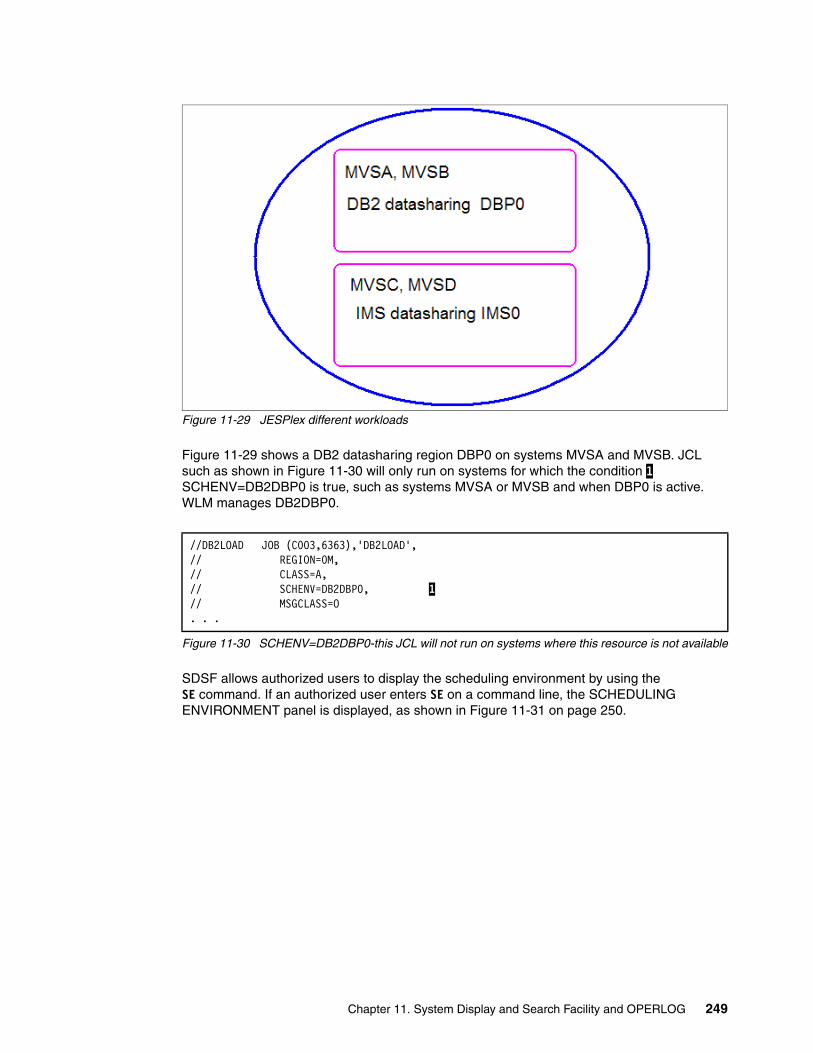
Figure 11-29 JESPlex different workloads
Figure 11-29 shows a DB2 datasharing region DBP0 on systems MVSA and MVSB. JCL such as shown in Figure 11-30 will only run on systems for which the condition 1 SCHENV=DB2DBP0 is true, such as systems MVSA or MVSB and when DBP0 is active. WLM manages DB2DBP0.
Figure 11-30 SCHENV=DB2DBP0-this JCL will not run on systems where this resource is not available
SDSF allows authorized users to display the scheduling environment by using the SE command. If an authorized user enters SE on a command line, the SCHEDULING ENVIRONMENT panel is displayed, as shown in Figure 11-31 on page 250.
//DB2LOAD JOB (C003,6363),'DB2LOAD', // REGION=0M, // CLASS=A, // SCHENV=DB2DBP0, 1// MSGCLASS=O . . .
Chapter 11. System Display and Search Facility and OPERLOG 249

Figure 11-31 SCHEDULING ENVIRONMENT panel example
To display resources for a scheduling environment, access the panel with the R action character, as seen in Figure 11-32.
Figure 11-32 SDSF Select select scheduling resource
R To find the resources that are required to be available when work under this environment can be run.
Figure 11-33 on page 251 shows that for work scheduled as BATCHUPDATES to run, then two resources need to resolved. DB2_PROD has to be ON and PRIME_SHIFT has to be OFF. A resource can have three values, ON, OFF, and RESET.
For more detailed information about the topic of resources, refer to 11.12, “Using the RESOURCE (RES) command” on page 251.
Display Filter View Print Options Help -------------------------------------------------------------------------------ISFPCU41 DULING ENVIRONMENT DISPLAY MAS SYSTEMS LINE 1-13 (13) COMMAND INPUT ===> SCROLL ===> CSR NP SCHEDULING-ENV Description Systems BATCHUPDATESE off shift batch updates to DB CB390SE S/390 Component Broker SE DB_REORGSE reorganization of DB timeframe ONLINEPRODSE production online timeframe AFTERMIDNIGHT After Midnight Processing AFTER6PM After 6PM Processing FRIDAY Friday Processing MONDAY Monday Processing SATURDAY Saturday Processing SUNDAY Sunday Processing THURSDAY Thursday Processing #@$1,#@$2,#@$3 TUESDAY Tuesday Processing WEDNESDAY Wednesday Processing WEEKEND Weekend Processing
Display Filter View Print Options Help -------------------------------------------------------------------------------ISFPCU41 DULING ENVIRONMENT DISPLAY MAS SYSTEMS LINE 1-13 (13) COMMAND INPUT ===> SCROLL ===> CSR NP SCHEDULING-ENV Description Systems R BATCHUPDATESE off shift batch updates to DB CB390SE S/390 Component Broker SE DB_REORGSE reorganization of DB timeframe . . .
250 IBM z/OS Parallel Sysplex Operational Scenarios
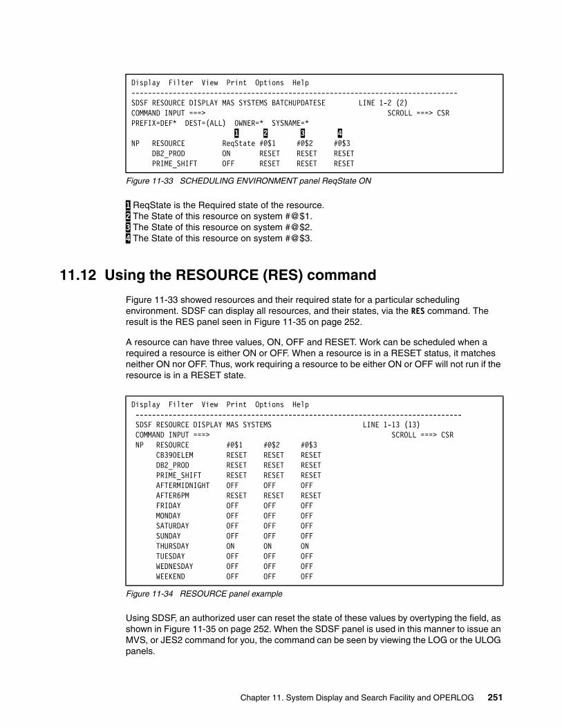
Figure 11-33 SCHEDULING ENVIRONMENT panel ReqState ON
1 ReqState is the Required state of the resource. 2 The State of this resource on system #@$1. 3 The State of this resource on system #@$2. 4 The State of this resource on system #@$3.
11.12 Using the RESOURCE (RES) command
Figure 11-33 showed resources and their required state for a particular scheduling environment. SDSF can display all resources, and their states, via the RES command. The result is the RES panel seen in Figure 11-35 on page 252.
A resource can have three values, ON, OFF and RESET. Work can be scheduled when a required a resource is either ON or OFF. When a resource is in a RESET status, it matches neither ON nor OFF. Thus, work requiring a resource to be either ON or OFF will not run if the resource is in a RESET state.
Figure 11-34 RESOURCE panel example
Using SDSF, an authorized user can reset the state of these values by overtyping the field, as shown in Figure 11-35 on page 252. When the SDSF panel is used in this manner to issue an MVS, or JES2 command for you, the command can be seen by viewing the LOG or the ULOG panels.
Display Filter View Print Options Help -------------------------------------------------------------------------------SDSF RESOURCE DISPLAY MAS SYSTEMS BATCHUPDATESE LINE 1-2 (2) COMMAND INPUT ===> SCROLL ===> CSR PREFIX=DEF* DEST=(ALL) OWNER=* SYSNAME=* 1 2 3 4 NP RESOURCE ReqState #@$1 #@$2 #@$3 DB2_PROD ON RESET RESET RESET PRIME_SHIFT OFF RESET RESET RESET
Display Filter View Print Options Help ------------------------------------------------------------------------------- SDSF RESOURCE DISPLAY MAS SYSTEMS LINE 1-13 (13) COMMAND INPUT ===> SCROLL ===> CSR NP RESOURCE #@$1 #@$2 #@$3 CB390ELEM RESET RESET RESET DB2_PROD RESET RESET RESET PRIME_SHIFT RESET RESET RESET AFTERMIDNIGHT OFF OFF OFF AFTER6PM RESET RESET RESET FRIDAY OFF OFF OFF MONDAY OFF OFF OFF SATURDAY OFF OFF OFF SUNDAY OFF OFF OFF THURSDAY ON ON ON TUESDAY OFF OFF OFF WEDNESDAY OFF OFF OFF WEEKEND OFF OFF OFF
Chapter 11. System Display and Search Facility and OPERLOG 251

In this case the commands issued were:
RO #@$1,F WLM,RESOURCE=CB390ELEM,ON RO #@$2,F WLM,RESOURCE=CB390ELEM,ON
The ability to reset the WLM resources can, and should, be restricted by a security product such as RACF.
Figure 11-35 Change Resource state
For more information about the RES command, refer to SDSF Operation and Customization, SA22-7670.
11.13 SDSF and ARM
SDSF runs a batch SDSF server task. If this task is not active, then the LOG and OPERLOG may not work, as can be seen in Figure 11-36. The server task can be defined to ARM for automatic restart. Refer to SDSF Operation and Customization, SA22-7670, for a detailed description of ARM configuration. You can also refer to Chapter 6, “Automatic Restart Manager” on page 83, to see an example of configuring the SDSF server task to be restarted if it abends.
Figure 11-36 SDSF LOG function inoperative
11.14 SDSF and the system IBM Health Checker
The IBM Health Checker for z/OS provides a foundation to help simplify and automate the identification of potential configuration problems before they impact system availability. Individual products, z/OS components, or ISV software can provide checks that take advantage of the IBM Health Checker for z/OS framework. The system Health Checker is a started task named HZSPROC. If the STC is not active, then the system health checker is not active.
SDSF has built-in support for the Health Checker. This is accessed by using the CK option. The output can be seen in Figure 11-37 on page 253. Normally you would only be interested in exception conditions; therefore, a SORT STATUS on the display is recommended. For more
Display Filter View Print Options Help -------------------------------------------------------------------------------SDSF RESOURCE DISPLAY MAS SYSTEMS LINE 1-3 (3) COMMAND INPUT ===> SCROLL ===> CSR NP RESOURCE #@$1 #@$2 #@$3 CB390ELEM on on RESET DB2_PROD RESET RESET RESET PRIME_SHIFT RESET RESET RESET
Display Filter View Print Options Help ------------------------------------------------------------------------------- HQX7720 ----------------- SDSF PRIMARY OPTION MENU --LOG FUNCTION INOPERATIVE COMMAND INPUT ===> SCROLL ===> CSR DA Active users INIT Initiators
252 IBM z/OS Parallel Sysplex Operational Scenarios
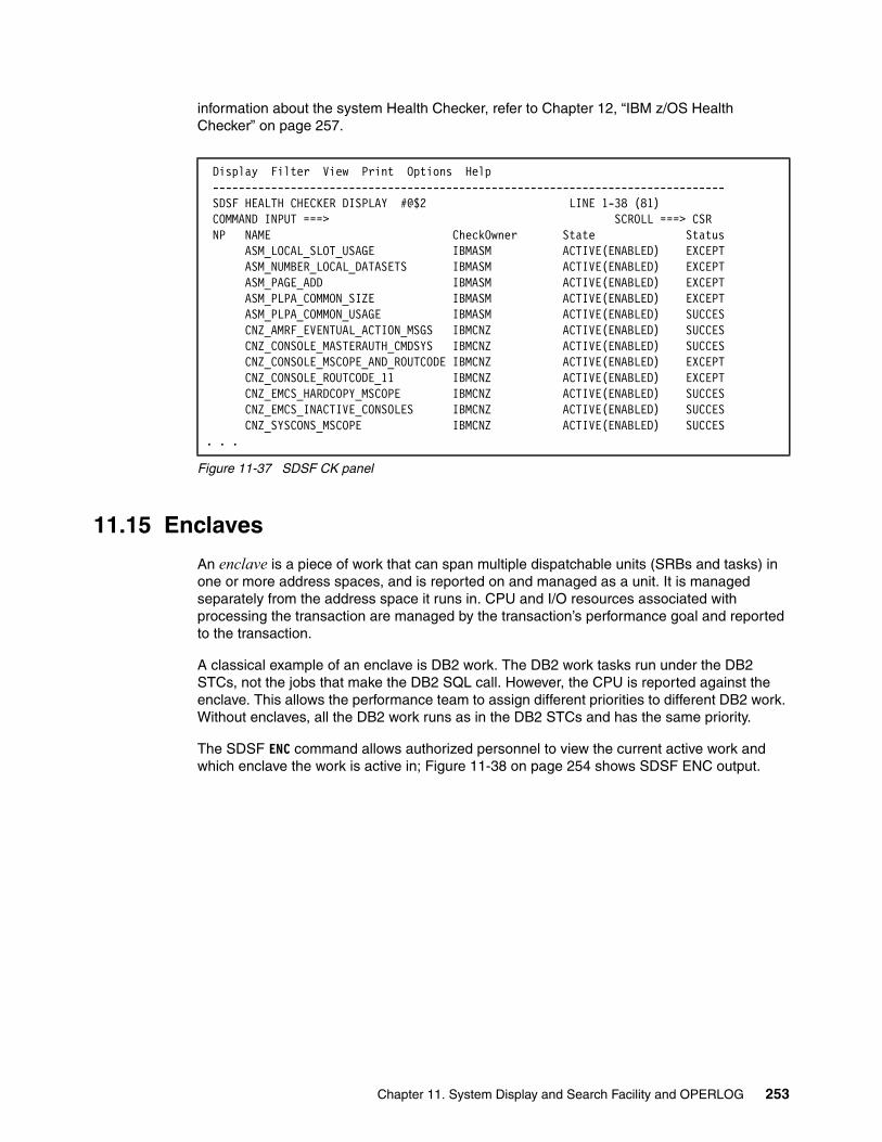
information about the system Health Checker, refer to Chapter 12, “IBM z/OS Health Checker” on page 257.
Figure 11-37 SDSF CK panel
11.15 Enclaves
An enclave is a piece of work that can span multiple dispatchable units (SRBs and tasks) in one or more address spaces, and is reported on and managed as a unit. It is managed separately from the address space it runs in. CPU and I/O resources associated with processing the transaction are managed by the transaction’s performance goal and reported to the transaction.
A classical example of an enclave is DB2 work. The DB2 work tasks run under the DB2 STCs, not the jobs that make the DB2 SQL call. However, the CPU is reported against the enclave. This allows the performance team to assign different priorities to different DB2 work. Without enclaves, all the DB2 work runs as in the DB2 STCs and has the same priority.
The SDSF ENC command allows authorized personnel to view the current active work and which enclave the work is active in; Figure 11-38 on page 254 shows SDSF ENC output.
Display Filter View Print Options Help ------------------------------------------------------------------------------- SDSF HEALTH CHECKER DISPLAY #@$2 LINE 1-38 (81) COMMAND INPUT ===> SCROLL ===> CSR NP NAME CheckOwner State Status ASM_LOCAL_SLOT_USAGE IBMASM ACTIVE(ENABLED) EXCEPT ASM_NUMBER_LOCAL_DATASETS IBMASM ACTIVE(ENABLED) EXCEPT ASM_PAGE_ADD IBMASM ACTIVE(ENABLED) EXCEPT ASM_PLPA_COMMON_SIZE IBMASM ACTIVE(ENABLED) EXCEPT ASM_PLPA_COMMON_USAGE IBMASM ACTIVE(ENABLED) SUCCES CNZ_AMRF_EVENTUAL_ACTION_MSGS IBMCNZ ACTIVE(ENABLED) SUCCES CNZ_CONSOLE_MASTERAUTH_CMDSYS IBMCNZ ACTIVE(ENABLED) SUCCES CNZ_CONSOLE_MSCOPE_AND_ROUTCODE IBMCNZ ACTIVE(ENABLED) EXCEPT CNZ_CONSOLE_ROUTCODE_11 IBMCNZ ACTIVE(ENABLED) EXCEPT CNZ_EMCS_HARDCOPY_MSCOPE IBMCNZ ACTIVE(ENABLED) SUCCES CNZ_EMCS_INACTIVE_CONSOLES IBMCNZ ACTIVE(ENABLED) SUCCES CNZ_SYSCONS_MSCOPE IBMCNZ ACTIVE(ENABLED) SUCCES. . .
Chapter 11. System Display and Search Facility and OPERLOG 253

Figure 11-38 SDSF ENC output
1 When some work is placed in an enclave, a token is created for WLM to manage this piece of work. Each piece of work has a unique token. 2 The work can be of various types; DDF means it is from a remote system (for example, AIX®). JES means it is from within the sysplex. 3 ACTIVE means doing work. INACTIVE means waiting for a resource. 4 Subsys indicates where the work came from. 5 OWNER indicates which job or STC made the DB2 call. D#$2DIST means it was a distributed call, which can be from outside of the sysplex.
Figure 11-39 SDSF ENC <scroll right>
Figure 11-39 shows the same token, 1. Notice which zAAP 2 and 3 and zIIP 4 and 5 resources have been used by these processes. However, in our test system, we have neither of these specialty engines, so the value is 0.
Figure 11-40 on page 255 shows the SDSF DA panel with two columns, ECPU% and ECPU-TIME. These columns display the CPU enclave usage for different jobs. A typical user of enclave work (and thus, ECPU-TIME) is DB2 DDF. This is DB2 distributed work where the DB2 query has come from another DB2 system. This can be from a different MVS image or another platform, such as AIX.
Display Filter View Print Options Help ------------------------------------------------------------------------------- SDSF ENCLAVE DISPLAY #@$1 ALL LINE 1-33 (33) COMMAND INPUT ===> SCROLL ===> CSR 1 2 3 4 5 PREFIX=COTTREL* DEST=(ALL) OWNER=* SYSNAME=* NP TOKEN SSType Status SrvClass Subsys OwnerJob Per PGN ResGro 60003D4328 DDF INACTIVE DDF_PBPP D#$# D#$2DIST 2 DDF_PB 200005DD1A1 DDF INACTIVE DDF_LO D#$# D#$2DIST 1 DDF_PB 2B4005CD227 DDF INACTIVE DDF_PBPP D#$# D#$3DIST 1 DDF_PB. . . 2FC005DD217 DDF INACTIVE DDF_LO D#$# D#$1DIST 1 DDF_PB 2DC005DE4AC JES ACTIVE CICS_LO JES2 #@$C1A1A 1
Display Filter View Print Options Help ------------------------------------------------------------------------------- SDSF ENCLAVE DISPLAY #@$1 ALL LINE 1-33 (33) COMMAND INPUT ===> SCROLL ===> CSR 1 2 3 4 5 PREFIX=COTTREL* DEST=(ALL) OWNER=* SYSNAME=* NP TOKEN zAAP-Time zACP-Time zIIP-Time zICP-Time 60003D4328 0.00 0.00 0.00 0.00 200005DD1A1 0.00 0.00 0.00 0.00 2B4005CD227 0.00 0.00 0.00 0.00 . . . 2FC005DD217 0.00 0.00 0.00 0.00 2DC005DE4AC 0.00 0.00 0.00 0.00
Note: zIIP and zAAP are specialty processors provided by IBM. Contact IBM, or see the IBM Web site at http://www.ibm.com, for further information about these processors.
254 IBM z/OS Parallel Sysplex Operational Scenarios
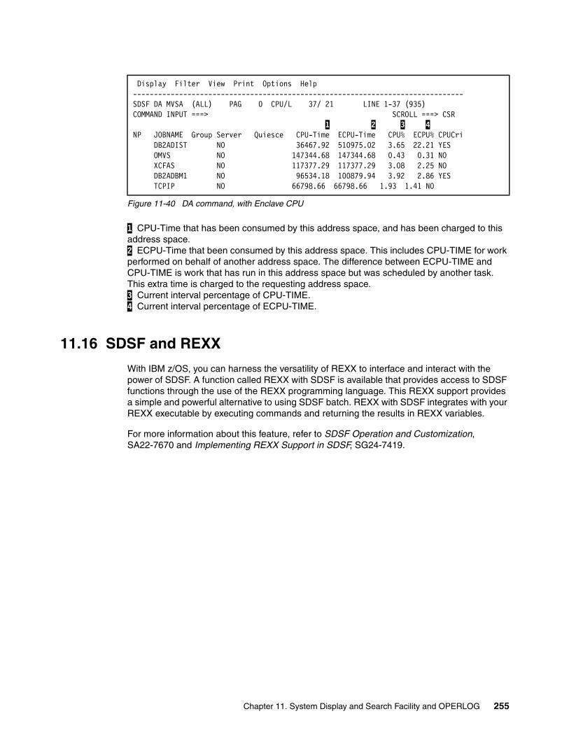
Figure 11-40 DA command, with Enclave CPU
1 CPU-Time that has been consumed by this address space, and has been charged to this address space. 2 ECPU-Time that been consumed by this address space. This includes CPU-TIME for work performed on behalf of another address space. The difference between ECPU-TIME and CPU-TIME is work that has run in this address space but was scheduled by another task. This extra time is charged to the requesting address space. 3 Current interval percentage of CPU-TIME. 4 Current interval percentage of ECPU-TIME.
11.16 SDSF and REXX
With IBM z/OS, you can harness the versatility of REXX to interface and interact with the power of SDSF. A function called REXX with SDSF is available that provides access to SDSF functions through the use of the REXX programming language. This REXX support provides a simple and powerful alternative to using SDSF batch. REXX with SDSF integrates with your REXX executable by executing commands and returning the results in REXX variables.
For more information about this feature, refer to SDSF Operation and Customization, SA22-7670 and Implementing REXX Support in SDSF, SG24-7419.
Display Filter View Print Options Help -------------------------------------------------------------------------------SDSF DA MVSA (ALL) PAG 0 CPU/L 37/ 21 LINE 1-37 (935) COMMAND INPUT ===> SCROLL ===> CSR 1 2 3 4 NP JOBNAME Group Server Quiesce CPU-Time ECPU-Time CPU% ECPU% CPUCri DB2ADIST NO 36467.92 510975.02 3.65 22.21 YES OMVS NO 147344.68 147344.68 0.43 0.31 NO XCFAS NO 117377.29 117377.29 3.08 2.25 NO DB2ADBM1 NO 96534.18 100879.94 3.92 2.86 YES TCPIP NO 66798.66 66798.66 1.93 1.41 NO
Chapter 11. System Display and Search Facility and OPERLOG 255

256 IBM z/OS Parallel Sysplex Operational Scenarios
Chapter 12. IBM z/OS Health Checker
This chapter provides details of operational considerations for the IBM z/OS Health Checker environment on a Parallel Sysplex environment. It includes:
� Introduction to z/OS Health Checker
� List of checks available by component
� Useful commands
12
© Copyright IBM Corp. 2009. All rights reserved. 257
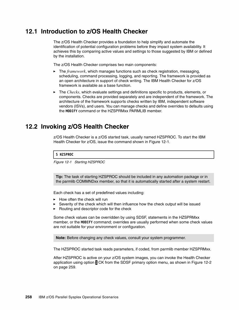
12.1 Introduction to z/OS Health Checker
The z/OS Health Checker provides a foundation to help simplify and automate the identification of potential configuration problems before they impact system availability. It achieves this by comparing active values and settings to those suggested by IBM or defined by the installation.
The z/OS Health Checker comprises two main components:
� The framework, which manages functions such as check registration, messaging, scheduling, command processing, logging, and reporting. The framework is provided as an open architecture in support of check writing. The IBM Health Checker for z/OS framework is available as a base function.
� The Checks, which evaluate settings and definitions specific to products, elements, or components. Checks are provided separately and are independent of the framework. The architecture of the framework supports checks written by IBM, independent software vendors (ISVs), and users. You can manage checks and define overrides to defaults using the MODIFY command or the HZSPRMxx PARMLIB member.
12.2 Invoking z/OS Health Checker
z/OS Health Checker is a z/OS started task, usually named HZSPROC. To start the IBM Health Checker for z/OS, issue the command shown in Figure 12-1.
Figure 12-1 Starting HZSPROC
Each check has a set of predefined values including:
� How often the check will run� Severity of the check which will then influence how the check output will be issued� Routing and descriptor code for the check
Some check values can be overridden by using SDSF, statements in the HZSPRMxx member, or the MODIFY command; overrides are usually performed when some check values are not suitable for your environment or configuration.
The HZSPROC started task reads parameters, if coded, from parmlib member HZSPRMxx.
After HZSPROC is active on your z/OS system images, you can invoke the Health Checker application using option 1 CK from the SDSF primary option menu, as shown in Figure 12-2 on page 259.
S HZSPROC
Tip: The task of starting HZSPROC should be included in any automation package or in the parmlib COMMNDxx member, so that it is automatically started after a system restart.
Note: Before changing any check values, consult your system programmer.
258 IBM z/OS Parallel Sysplex Operational Scenarios
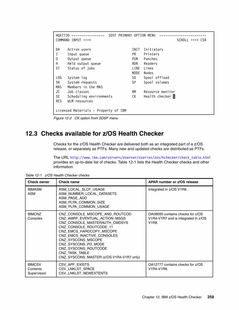
Figure 12-2 CK option from SDSF menu
12.3 Checks available for z/OS Health Checker
Checks for the z/OS Health Checker are delivered both as an integrated part of a z/OS release, or separately as PTFs. Many new and updated checks are distributed as PTFs.
The URL http://www.ibm.com/servers/eserver/zseries/zos/hchecker/check_table.html provides an up-to-date list of checks. Table 12-1 lists the Health Checker checks and other information.
Table 12-1 z/OS Health Checker checks
HQX7730 ----------------- SDSF PRIMARY OPTION MENU ------------------------COMMAND INPUT ===> SCROLL ===> CSR DA Active users INIT Initiators I Input queue PR Printers O Output queue PUN Punches H Held output queue RDR Readers ST Status of jobs LINE Lines NODE Nodes LOG System log SO Spool offload SR System requests SP Spool volumes MAS Members in the MAS JC Job classes RM Resource monitor SE Scheduling environments CK Health checker 1RES WLM resources Licensed Materials - Property of IBM
Check owner Check name APAR number or z/OS release
IBMASMASM
ASM_LOCAL_SLOT_USAGEASM_NUMBER_LOCAL_DATASETSASM_PAGE_ADDASM_PLPA_COMMON_SIZEASM_PLPA_COMMON_USAGE
Integrated in z/OS V1R8.
IBMCNZConsoles
CNZ_CONSOLE_MSCOPE_AND_ROUTCODCNZ_AMRF_EVENTUAL_ACTION_MSGS CNZ_CONSOLE_MASTERAUTH_CMDSYSCNZ_CONSOLE_ROUTCODE_11CNZ_EMCS_HARDCOPY_MSCOPECNZ_EMCS_INACTIVE_CONSOLES CNZ_SYSCONS_MSCOPECNZ_SYSCONS_PD_MODECNZ_SYSCONS_ROUTCODECNZ_TASK_TABLECNZ_SYSCONS_MASTER (z/OS V1R4-V1R7 only)
OA09095 contains checks for z/OS V1R4-V1R7 and is integrated in z/OS V1R8.
IBMCSVContents Supervision
CSV_APF_EXISTSCSV_LNKLST_SPACECSV_LNKLST_NEWEXTENTS
OA12777 contains checks for z/OS V1R4-V1R8.
Chapter 12. IBM z/OS Health Checker 259
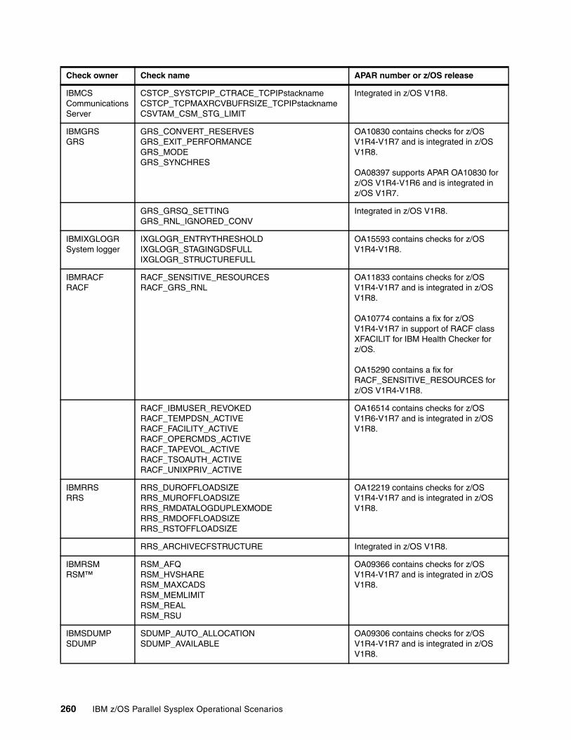
IBMCSCommunicationsServer
CSTCP_SYSTCPIP_CTRACE_TCPIPstacknameCSTCP_TCPMAXRCVBUFRSIZE_TCPIPstacknameCSVTAM_CSM_STG_LIMIT
Integrated in z/OS V1R8.
IBMGRSGRS
GRS_CONVERT_RESERVESGRS_EXIT_PERFORMANCEGRS_MODEGRS_SYNCHRES
OA10830 contains checks for z/OS V1R4-V1R7 and is integrated in z/OS V1R8.
OA08397 supports APAR OA10830 for z/OS V1R4-V1R6 and is integrated in z/OS V1R7.
GRS_GRSQ_SETTINGGRS_RNL_IGNORED_CONV
Integrated in z/OS V1R8.
IBMIXGLOGRSystem logger
IXGLOGR_ENTRYTHRESHOLDIXGLOGR_STAGINGDSFULLIXGLOGR_STRUCTUREFULL
OA15593 contains checks for z/OS V1R4-V1R8.
IBMRACFRACF
RACF_SENSITIVE_RESOURCESRACF_GRS_RNL
OA11833 contains checks for z/OS V1R4-V1R7 and is integrated in z/OS V1R8.
OA10774 contains a fix for z/OS V1R4-V1R7 in support of RACF class XFACILIT for IBM Health Checker for z/OS.
OA15290 contains a fix for RACF_SENSITIVE_RESOURCES for z/OS V1R4-V1R8.
RACF_IBMUSER_REVOKEDRACF_TEMPDSN_ACTIVERACF_FACILITY_ACTIVERACF_OPERCMDS_ACTIVERACF_TAPEVOL_ACTIVERACF_TSOAUTH_ACTIVERACF_UNIXPRIV_ACTIVE
OA16514 contains checks for z/OS V1R6-V1R7 and is integrated in z/OS V1R8.
IBMRRS RRS
RRS_DUROFFLOADSIZERRS_MUROFFLOADSIZERRS_RMDATALOGDUPLEXMODERRS_RMDOFFLOADSIZERRS_RSTOFFLOADSIZE
OA12219 contains checks for z/OS V1R4-V1R7 and is integrated in z/OS V1R8.
RRS_ARCHIVECFSTRUCTURE Integrated in z/OS V1R8.
IBMRSMRSM™
RSM_AFQRSM_HVSHARE RSM_MAXCADS RSM_MEMLIMITRSM_REALRSM_RSU
OA09366 contains checks for z/OS V1R4-V1R7 and is integrated in z/OS V1R8.
IBMSDUMPSDUMP
SDUMP_AUTO_ALLOCATIONSDUMP_AVAILABLE
OA09306 contains checks for z/OS V1R4-V1R7 and is integrated in z/OS V1R8.
Check owner Check name APAR number or z/OS release
260 IBM z/OS Parallel Sysplex Operational Scenarios

12.4 Working with check output
After z/OS Health Checker has been configured and started on your z/OS system images, output from the checks is in the form of messages issued by check routines as either:
� Exception messages issued when a check detects a potential problem or a deviation from a suggested setting
� Information messages issued to the message buffer to indicate either a clean run (no exceptions found) or that a check is not appropriate in the current environment and will not run
� Reports issued to the message buffer, often as supplementary information for an exception message
IBMUSSz/OS UNIX
USS_AUTOMOUNT_DELAYUSS_FILESYS_CONFIGUSS_MAXSOCKETS_MAXFILEPROC
OA09276 contains checks for z/OS V1R4 - V1R7 and is integrated in z/OS V1R8.
OA14022 and OA14576 contain fixes for the USS_FILESYS_CONFIG check for z/OS V1R4-V1R7.
IBMVSAMVSAM
VSAM_SINGLE_POINT_FAILURE OA17782 contains checks for z/OS V1R8.
VSAMRLS_DIAG_CONTENTION OA17734 contains checks for z/OS V1R8.
VSAM_ INDEX_TRAP OA15539 contains this check for z/OS V1R8.
IBMVSMVSM
VSM_CSA_CHANGEVSM_CSA_LIMITVSM_CSA_THRESHOLDVSM_PVT_LIMITVSM_SQA_LIMITVSM_SQA_THRESHOLD
OA09367 contains checks for z/OS V1R4-V1R7 and is integrated in z/OS V1R8.
VSM_ALLOWUSERKEYCSA Integrated in z/OS V1R8.
IBMXCFXCF
XCF_CF_STR_PREFLISTXCF_CDS_SEPARATIONXCF_CF_CONNECTIVITYXCF_CF_STR_EXCLLISTXCF_CLEANUP_VALUEXCF_DEFAULT_MAXMSGXCF_FDIXCF_MAXMSG_NUMBUF_RATIOXCF_SFM_ACTIVEXCF_SIG_CONNECTIVITYXCF_SIG_PATH_SEPARATIONXCF_SIG_STR_SIZEXCF_SYSPLEX_CDS_CAPACITYXCF_TCLASS_CLASSLENXCF_TCLASS_CONNECTIVITYXCF_TCLASS_HAS_UNDESIG
OA07513 contains checks for z/OS V1R4-V1R7 and is integrated in z/OS V1R8.
OA14637 contains a fix for the XCF checks for z/OS V1R4-V1R7.
Check owner Check name APAR number or z/OS release
Chapter 12. IBM z/OS Health Checker 261
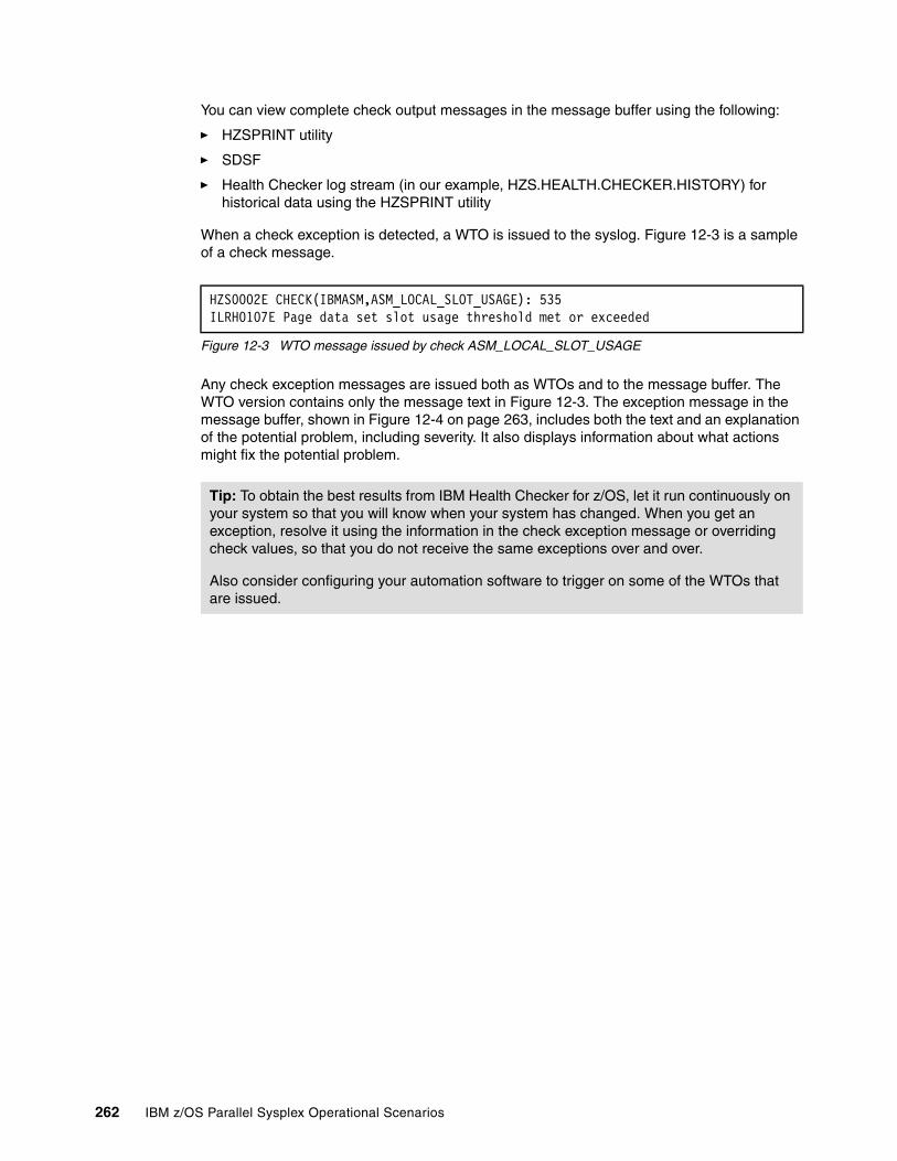
You can view complete check output messages in the message buffer using the following:
� HZSPRINT utility
� SDSF
� Health Checker log stream (in our example, HZS.HEALTH.CHECKER.HISTORY) for historical data using the HZSPRINT utility
When a check exception is detected, a WTO is issued to the syslog. Figure 12-3 is a sample of a check message.
Figure 12-3 WTO message issued by check ASM_LOCAL_SLOT_USAGE
Any check exception messages are issued both as WTOs and to the message buffer. The WTO version contains only the message text in Figure 12-3. The exception message in the message buffer, shown in Figure 12-4 on page 263, includes both the text and an explanation of the potential problem, including severity. It also displays information about what actions might fix the potential problem.
HZS0002E CHECK(IBMASM,ASM_LOCAL_SLOT_USAGE): 535 ILRH0107E Page data set slot usage threshold met or exceeded
Tip: To obtain the best results from IBM Health Checker for z/OS, let it run continuously on your system so that you will know when your system has changed. When you get an exception, resolve it using the information in the check exception message or overriding check values, so that you do not receive the same exceptions over and over.
Also consider configuring your automation software to trigger on some of the WTOs that are issued.
262 IBM z/OS Parallel Sysplex Operational Scenarios
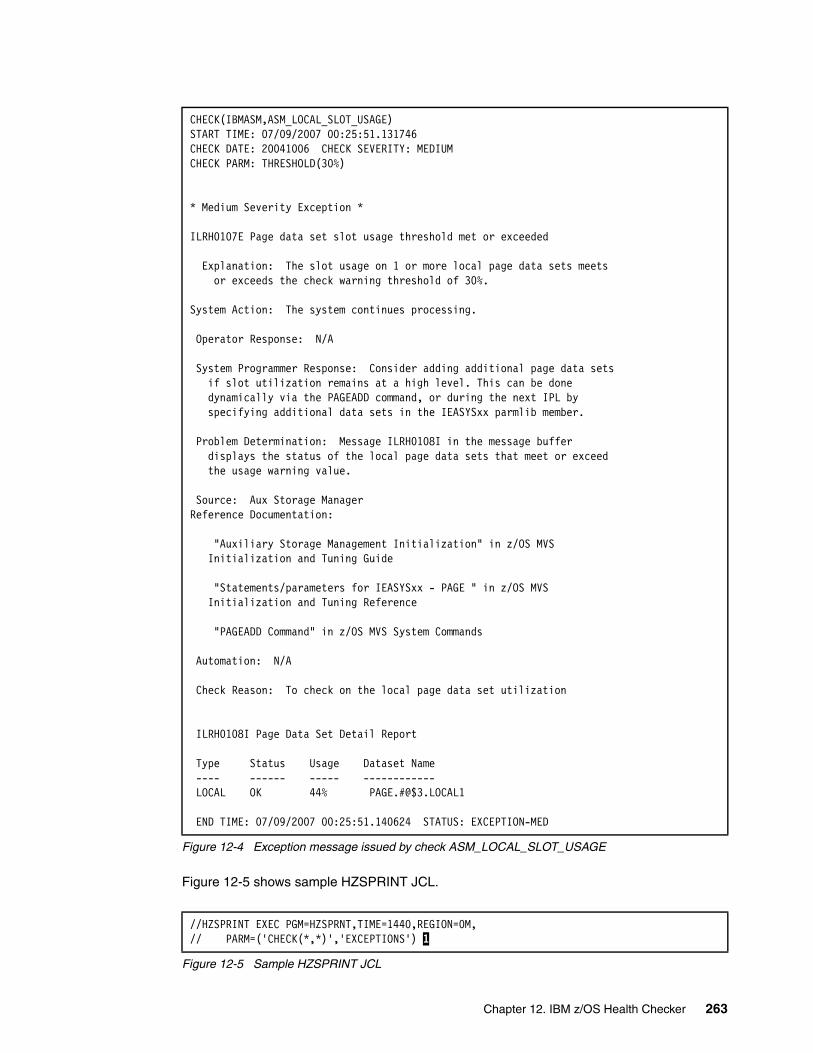
Figure 12-4 Exception message issued by check ASM_LOCAL_SLOT_USAGE
Figure 12-5 shows sample HZSPRINT JCL.
Figure 12-5 Sample HZSPRINT JCL
CHECK(IBMASM,ASM_LOCAL_SLOT_USAGE) START TIME: 07/09/2007 00:25:51.131746 CHECK DATE: 20041006 CHECK SEVERITY: MEDIUM CHECK PARM: THRESHOLD(30%) * Medium Severity Exception * ILRH0107E Page data set slot usage threshold met or exceeded Explanation: The slot usage on 1 or more local page data sets meets or exceeds the check warning threshold of 30%. System Action: The system continues processing. Operator Response: N/A System Programmer Response: Consider adding additional page data sets if slot utilization remains at a high level. This can be done dynamically via the PAGEADD command, or during the next IPL by specifying additional data sets in the IEASYSxx parmlib member. Problem Determination: Message ILRH0108I in the message buffer displays the status of the local page data sets that meet or exceed the usage warning value. Source: Aux Storage Manager Reference Documentation: "Auxiliary Storage Management Initialization" in z/OS MVS Initialization and Tuning Guide "Statements/parameters for IEASYSxx - PAGE " in z/OS MVS Initialization and Tuning Reference "PAGEADD Command" in z/OS MVS System Commands Automation: N/A Check Reason: To check on the local page data set utilization
ILRH0108I Page Data Set Detail Report Type Status Usage Dataset Name ---- ------ ----- ------------ LOCAL OK 44% PAGE.#@$3.LOCAL1 END TIME: 07/09/2007 00:25:51.140624 STATUS: EXCEPTION-MED
//HZSPRINT EXEC PGM=HZSPRNT,TIME=1440,REGION=0M, // PARM=('CHECK(*,*)','EXCEPTIONS') 1
Chapter 12. IBM z/OS Health Checker 263
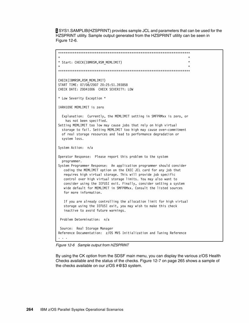
1 SYS1.SAMPLIB(HZSPRINT) provides sample JCL and parameters that can be used for the HZSPRINT utility. Sample output generated from the HZSPRINT utility can be seen in Figure 12-6.
Figure 12-6 Sample output from HZSPRINT
By using the CK option from the SDSF main menu, you can display the various z/OS Health Checks available and the status of the checks. Figure 12-7 on page 265 shows a sample of the checks available on our z/OS #@$3 system.
************************************************************************ * * * Start: CHECK(IBMRSM,RSM_MEMLIMIT) * * * ************************************************************************ CHECK(IBMRSM,RSM_MEMLIMIT) START TIME: 07/08/2007 20:25:51.393858 CHECK DATE: 20041006 CHECK SEVERITY: LOW * Low Severity Exception * IARH109E MEMLIMIT is zero Explanation: Currently, the MEMLIMIT setting in SMFPRMxx is zero, or has not been specified. Setting MEMLIMIT too low may cause jobs that rely on high virtual storage to fail. Setting MEMLIMIT too high may cause over-commitment of real storage resources and lead to performance degradation or system loss. System Action: n/a Operator Response: Please report this problem to the system programmer. System Programmer Response: An application programmer should consider coding the MEMLIMIT option on the EXEC JCL card for any job that requires high virtual storage. This will provide job specific control over high virtual storage limits. You may also want to consider using the IEFUSI exit. Finally, consider setting a system wide default for MEMLIMIT in SMFPRMxx. Consult the listed sources for more information. If you are already controlling the allocation limit for high virtual storage using the IEFUSI exit, you may wish to make this check inactive to avoid future warnings. Problem Determination: n/a Source: Real Storage Manager Reference Documentation: z/OS MVS Initialization and Tuning Reference . . .
264 IBM z/OS Parallel Sysplex Operational Scenarios
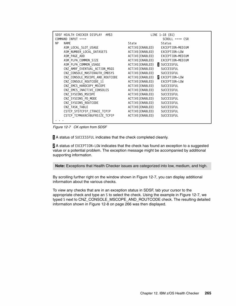
Figure 12-7 CK option from SDSF
1 A status of SUCCESSFUL indicates that the check completed cleanly.
2 A status of EXCEPTION-LOW indicates that the check has found an exception to a suggested value or a potential problem. The exception message might be accompanied by additional supporting information.
By scrolling further right on the window shown in Figure 12-7, you can display additional information about the various checks.
To view any checks that are in an exception status in SDSF, tab your cursor to the appropriate check and type an S to select the check. Using the example in Figure 12-7, we typed S next to CNZ_CONSOLE_MSCOPE_AND_ROUTCODE check. The resulting detailed information shown in Figure 12-8 on page 266 was then displayed.
SDSF HEALTH CHECKER DISPLAY #@$3 LINE 1-18 (81) COMMAND INPUT ===> SCROLL ===> CSRNP NAME State Status ASM_LOCAL_SLOT_USAGE ACTIVE(ENABLED) EXCEPTION-MEDIUM ASM_NUMBER_LOCAL_DATASETS ACTIVE(ENABLED) EXCEPTION-LOW ASM_PAGE_ADD ACTIVE(ENABLED) EXCEPTION-MEDIUM ASM_PLPA_COMMON_SIZE ACTIVE(ENABLED) EXCEPTION-MEDIUM ASM_PLPA_COMMON_USAGE ACTIVE(ENABLED) 1 SUCCESSFUL CNZ_AMRF_EVENTUAL_ACTION_MSGS ACTIVE(ENABLED) SUCCESSFUL CNZ_CONSOLE_MASTERAUTH_CMDSYS ACTIVE(ENABLED) SUCCESSFUL
CNZ_CONSOLE_MSCOPE_AND_ROUTCODE ACTIVE(ENABLED) 2 EXCEPTION-LOW CNZ_CONSOLE_ROUTCODE_11 ACTIVE(ENABLED) EXCEPTION-LOW
CNZ_EMCS_HARDCOPY_MSCOPE ACTIVE(ENABLED) SUCCESSFUL CNZ_EMCS_INACTIVE_CONSOLES ACTIVE(ENABLED) SUCCESSFUL
CNZ_SYSCONS_MSCOPE ACTIVE(ENABLED) SUCCESSFUL CNZ_SYSCONS_PD_MODE ACTIVE(ENABLED) SUCCESSFUL
CNZ_SYSCONS_ROUTCODE ACTIVE(ENABLED) SUCCESSFUL CNZ_TASK_TABLE ACTIVE(ENABLED) SUCCESSFUL
CSTCP_SYSTCPIP_CTRACE_TCPIP ACTIVE(ENABLED) SUCCESSFUL CSTCP_TCPMAXRCVBUFRSIZE_TCPIP ACTIVE(ENABLED) SUCCESSFUL
. . .
Note: Exceptions that Health Checker issues are categorized into low, medium, and high.
Chapter 12. IBM z/OS Health Checker 265

Figure 12-8 Detailed information about a specific check
Using the HZSPRINT utility with the LOGSTREAM keyword, check reports can be generated from the log stream; see Figure 12-9 on page 267. In our Parallel Sysplex environment, the
CHECK(IBMCNZ,CNZ_CONSOLE_MSCOPE_AND_ROUTCODE) START TIME: 07/08/2007 20:25:51.078025 CHECK DATE: 20040816 CHECK SEVERITY: LOW There is a total of 10 consoles (1 active, 9 inactive) that are configured with a combination of message scope and routing code values that are not reasonable. Console Console Active Type Name System MSCOPE MCS #@$3M01 #@$3 *ALL MCS #@$3M02 (Inactive) *ALL SMCS CON1 (Inactive) *ALL SMCS CON2 (Inactive) *ALL . . .* Low Severity Exception * CNZHF0003I One or more consoles are configured with a combination of message scope and routing code values that are not reasonable. Explanation: One or more consoles have been configured to have a multi-system message scope and either all routing codes or all routing codes except routing code 11. Note: For active MCS and SMCS consoles, only the consoles active on this system are checked. For inactive MCS and SMCS consoles, all consoles are checked. All EMCS consoles are checked. System Action: The system continues processing. Operator Response: Report this problem to the system programmer. System Programmer Response: To view the attributes of all consoles, issue the following commands: DISPLAY CONSOLES,L DISPLAY EMCS,FULL,STATUS=L Update the MSCOPE or ROUTCODE parameters of MCS and SMCS consoles on the CONSOLE statement in the CONSOLxx parmlib member before the next IPL. For EMCS consoles (or to have the updates to MCS/SMCS consoles in effect immediately), you may update the message scope and routing code parameters by issuing the VARY CN system command with either the MSCOPE, DMSCOPE, ROUT or DROUT parameters. If an EMCS console is not active, find out which product activated it and contact the product owner. Effective with z/OS V1R7, you can use the EMCS console removal service (IEARELEC in SYS1.SAMPLIB) to remove any EMCS console definition that is no longer needed. . . . Problem Determination: n/a Automation: n/a Check Reason: Reduces the number of messages sent to a console in the sysplex ND TIME: 07/08/2007 20:25:51.352692 STATUS: EXCEPTION-LOW
266 IBM z/OS Parallel Sysplex Operational Scenarios
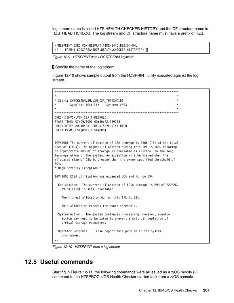
log stream name is called HZS.HEALTH.CHECKER.HISTORY and the CF structure name is HZS_HEALTHCKLOG. The log stream and CF structure name must have a prefix of HZS.
Figure 12-9 HZSPRINT with LOGSTREAM keyword
1 Specify the name of the log stream.
Figure 12-10 shows sample output from the HZSPRINT utility executed against the log stream.
Figure 12-10 HZSPRINT from a log stream
12.5 Useful commands
Starting in Figure 12-11, the following commands were all issued as a z/OS modify (F) command to the HZSPROC z/OS Health Checker started task from a z/OS console.
//HZSPRINT EXEC PGM=HZSPRNT,TIME=1440,REGION=0M, // PARM=('LOGSTREAM(HZS.HEALTH.CHECKER.HISTORY)') 1
************************************************************************ * * * Start: CHECK(IBMVSM,VSM_CSA_THRESHOLD) * * Sysplex: #@$#PLEX System: #@$3 * * * ************************************************************************ CHECK(IBMVSM,VSM_CSA_THRESHOLD) START TIME: 07/09/2007 00:30:52.739128 CHECK DATE: 20040405 CHECK SEVERITY: HIGH CHECK PARM: CSA(80%),ECSA(80%) IGVH100I The current allocation of CSA storage is 756K (15% of the total size of 4760K). The highest allocation during this IPL is 16%. Ensuring an appropriate amount of storage is available is critical to the long term operation of the system. An exception will be issued when the allocated size of CSA is greater than the owner specified threshold of 80%. * High Severity Exception * IGVH100E ECSA utilization has exceeded 80% and is now 89% Explanation: The current allocation of ECSA storage is 89% of 72288K. 7916K (11%) is still available. The highest allocation during this IPL is 89%. This allocation exceeds the owner threshold. System Action: The system continues processing. However, eventual action may need to be taken to prevent a critical depletion of virtual storage resources. Operator Response: Please report this problem to the system programmer. ...
Chapter 12. IBM z/OS Health Checker 267
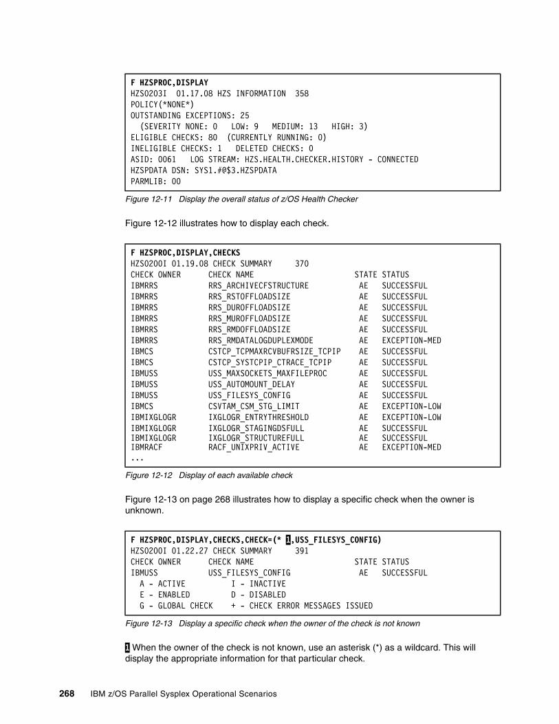
Figure 12-11 Display the overall status of z/OS Health Checker
Figure 12-12 illustrates how to display each check.
Figure 12-12 Display of each available check
Figure 12-13 on page 268 illustrates how to display a specific check when the owner is unknown.
Figure 12-13 Display a specific check when the owner of the check is not known
1 When the owner of the check is not known, use an asterisk (*) as a wildcard. This will display the appropriate information for that particular check.
F HZSPROC,DISPLAY HZS0203I 01.17.08 HZS INFORMATION 358 POLICY(*NONE*) OUTSTANDING EXCEPTIONS: 25 (SEVERITY NONE: 0 LOW: 9 MEDIUM: 13 HIGH: 3) ELIGIBLE CHECKS: 80 (CURRENTLY RUNNING: 0) INELIGIBLE CHECKS: 1 DELETED CHECKS: 0 ASID: 0061 LOG STREAM: HZS.HEALTH.CHECKER.HISTORY - CONNECTED HZSPDATA DSN: SYS1.#@$3.HZSPDATA PARMLIB: 00
F HZSPROC,DISPLAY,CHECKS HZS0200I 01.19.08 CHECK SUMMARY 370 CHECK OWNER CHECK NAME STATE STATUS IBMRRS RRS_ARCHIVECFSTRUCTURE AE SUCCESSFUL IBMRRS RRS_RSTOFFLOADSIZE AE SUCCESSFUL IBMRRS RRS_DUROFFLOADSIZE AE SUCCESSFUL IBMRRS RRS_MUROFFLOADSIZE AE SUCCESSFUL IBMRRS RRS_RMDOFFLOADSIZE AE SUCCESSFUL IBMRRS RRS_RMDATALOGDUPLEXMODE AE EXCEPTION-MED IBMCS CSTCP_TCPMAXRCVBUFRSIZE_TCPIP AE SUCCESSFUL IBMCS CSTCP_SYSTCPIP_CTRACE_TCPIP AE SUCCESSFUL IBMUSS USS_MAXSOCKETS_MAXFILEPROC AE SUCCESSFUL IBMUSS USS_AUTOMOUNT_DELAY AE SUCCESSFUL IBMUSS USS_FILESYS_CONFIG AE SUCCESSFUL IBMCS CSVTAM_CSM_STG_LIMIT AE EXCEPTION-LOW IBMIXGLOGR IXGLOGR_ENTRYTHRESHOLD AE EXCEPTION-LOW IBMIXGLOGR IXGLOGR_STAGINGDSFULL AE SUCCESSFUL IBMIXGLOGR IXGLOGR_STRUCTUREFULL AE SUCCESSFUL IBMRACF RACF_UNIXPRIV_ACTIVE AE EXCEPTION-MED ...
F HZSPROC,DISPLAY,CHECKS,CHECK=(* 1,USS_FILESYS_CONFIG) HZS0200I 01.22.27 CHECK SUMMARY 391 CHECK OWNER CHECK NAME STATE STATUS IBMUSS USS_FILESYS_CONFIG AE SUCCESSFUL A - ACTIVE I - INACTIVE E - ENABLED D - DISABLED G - GLOBAL CHECK + - CHECK ERROR MESSAGES ISSUED
268 IBM z/OS Parallel Sysplex Operational Scenarios
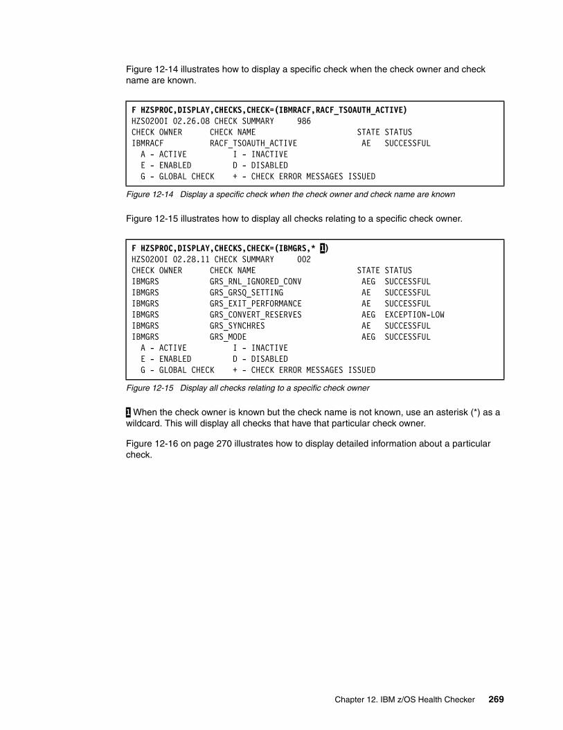
Figure 12-14 illustrates how to display a specific check when the check owner and check name are known.
Figure 12-14 Display a specific check when the check owner and check name are known
Figure 12-15 illustrates how to display all checks relating to a specific check owner.
Figure 12-15 Display all checks relating to a specific check owner
1 When the check owner is known but the check name is not known, use an asterisk (*) as a wildcard. This will display all checks that have that particular check owner.
Figure 12-16 on page 270 illustrates how to display detailed information about a particular check.
F HZSPROC,DISPLAY,CHECKS,CHECK=(IBMRACF,RACF_TSOAUTH_ACTIVE) HZS0200I 02.26.08 CHECK SUMMARY 986 CHECK OWNER CHECK NAME STATE STATUS IBMRACF RACF_TSOAUTH_ACTIVE AE SUCCESSFUL A - ACTIVE I - INACTIVE E - ENABLED D - DISABLED G - GLOBAL CHECK + - CHECK ERROR MESSAGES ISSUED
F HZSPROC,DISPLAY,CHECKS,CHECK=(IBMGRS,* 1) HZS0200I 02.28.11 CHECK SUMMARY 002 CHECK OWNER CHECK NAME STATE STATUS IBMGRS GRS_RNL_IGNORED_CONV AEG SUCCESSFUL IBMGRS GRS_GRSQ_SETTING AE SUCCESSFUL IBMGRS GRS_EXIT_PERFORMANCE AE SUCCESSFUL IBMGRS GRS_CONVERT_RESERVES AEG EXCEPTION-LOWIBMGRS GRS_SYNCHRES AE SUCCESSFUL IBMGRS GRS_MODE AEG SUCCESSFUL A - ACTIVE I - INACTIVE E - ENABLED D - DISABLED G - GLOBAL CHECK + - CHECK ERROR MESSAGES ISSUED
Chapter 12. IBM z/OS Health Checker 269

Figure 12-16 Display detailed information for a particular check
For additional information about z/OS Health Checker, refer to IBM Health Checker for z/OS Users Guide, SA22-7994.
F HZSPROC,DISPLAY,CHECKS,CHECK=(IBMGRS,GRS_CONVERT_RESERVES),DETAIL HZS0201I 02.44.14 CHECK DETAIL 096 CHECK(IBMGRS,GRS_CONVERT_RESERVES) STATE: ACTIVE(ENABLED) GLOBAL STATUS: EXCEPTION-LOW EXITRTN: ISGHCADC LAST RAN: 07/08/2007 23:13 NEXT SCHEDULED: (NOT SCHEDULED) INTERVAL: ONETIME EXCEPTION INTERVAL: SYSTEM SEVERITY: LOW WTOTYPE: INFORMATIONAL SYSTEM DESCCODE: 12 THERE ARE NO PARAMETERS FOR THIS CHECK REASON FOR CHECK: When in STAR mode, converting RESERVEs can help improve performance and avoid deadlock. MODIFIED BY: N/A DEFAULT DATE: 20050105 ORIGIN: HZSADDCK LOCALE: HZSPROC DEBUG MODE: OFF VERBOSE MODE: NO
270 IBM z/OS Parallel Sysplex Operational Scenarios
Chapter 13. Managing JES3 in a Parallel Sysplex
This chapter discusses the following scenarios in a JES3 environment:
� Introduction to JES3
� JES3 job flow
� JES3 in a sysplex
� Dynamic System Interchange™ (DSI)
� JES3 networking with TCP/IP
� Useful JES3 operator commands
13
© Copyright IBM Corp. 2009. All rights reserved. 271
13.1 Introduction to JES3
A major goal of operating systems is to process jobs while making the best use of system resources. Thus, one way of viewing operating systems is as resource managers. Before job processing, operating systems reserve input and output resources for jobs. During job processing, operating systems manage resources such as processors and storage. After job processing, operating systems free all resources used by the completed jobs, thus making the resources available to other jobs. This process is called resource management.
There is more to the processing of jobs than just the managing of resources needed by the jobs, however. At any instant, a number of jobs can be in various stages of preparation, processing, and post-processing activity. To use resources efficiently, operating systems divide jobs into parts. They distribute the parts of jobs to queues to wait for needed resources. Keeping track of where things are and routing work from queue to queue is called workflow management, and it is a major function of any operating system.
With the z/OS JES3 system, resource management and workflow management are shared between z/OS and JES3. Generally speaking, JES3 performs resource management and workflow management before and after job execution. z/OS performs resource and workflow management during job execution.
JES3 considers job priorities, device and processor alternatives, and installation-specified preferences when preparing jobs for processing job output.
13.2 JES3 job flow
The JES3 job flow, whether in a Parallel Sysplex environment or not, has seven key phases:
1. Input service
JES3 input service accepts and queues all work entering the JES3 system. The global processor reads the work definitions into the system and creates JES3 job structures for them. Work is accepted from:
– A TSO SUBMIT command
– A local card reader
– A local tape reader
– A disk reader
– A remote work station
– Another node in a job entry network
– The internal reader
2. Converter/interpreter processing
After input service processing, a job passes through the JES3 converter/interpreter processing (C/I). As a result, JES3 learns about the resources the job requires during execution. C/I routines provide input to the main device scheduling (MDS) routines by determining available devices, volumes, and data sets. These service routines process the job’s JCL to create control blocks for setup and also prevent jobs with JCL errors from continuing in the system. The C/I section of setup processing is further divided into three phases:
– MVS converter/interpreter (C/I) processing
– Prescan processing
272 IBM z/OS Parallel Sysplex Operational Scenarios

– Postscan processing
The first two phases can occur in either the JES3 address space on the global processor or in the C/I functional subsystem address space on either the local or the global processor.
3. Job resource management
The next phase of JES3 job processing is called job resource management. The job resource management function provides for the effective use of system resources. JES3 main device scheduler (MDS) functionality, alias the setup, ensures the operative use of non-sharable mountable volumes, eliminates operator intervention during job execution, and performs data set serialization. It oversees specific types of pre-execution job setup and generally prepares all necessary resources to process the job. The main device scheduler routines use resource tables and allocation algorithms to satisfy a job’s requirements through the allocation of volumes and devices, and, if necessary, the serialization of data sets.
4. Generalized main scheduling
After a job is set up, it enters JES3 job scheduling. JES3 job scheduling is the group of services that govern where and when z/OS execution of a JES3 job occurs. Job scheduling controls the order and execution of jobs running within the JES3 complex.
5. Job execution
Jobs are scheduled to the waiting initiators on the JES3 main processors. For the sysplex environment, the use of Workload Manager (WLM) allows the optimization of resources to address spaces using goals defined for the various work using a WLM policy.
6. Output processing
The final part of JES3 job processing is called job output and termination. Output service routines operate in various phases to process SYSOUT data sets destined for print or punch devices (local, RJP, or NJE), TSO users, internal readers, external writers, and writer functional subsystems.
7. Purge processing
Purge processing represents the last JES3 processing step for any job. It releases the resources used during the job.
13.3 JES3 in a sysplex
JESXCF is an XCF application. It provides, based on XCF coupling services, common inter-processor and intra-processor communication services for both JES3 and JES2 subsystems, as illustrated in Figure 13-1 on page 274.
Chapter 13. Managing JES3 in a Parallel Sysplex 273

Figure 13-1 JES3 configuration in a sysplex
13.4 Global-only JES3 configuration
In this configuration there is a single z/OS and JES3 complex, as illustrated in Figure 13-2. The sysplex configuration is defined as either PLEXCFG=XCFLOCAL or PLEXCFG=MONOPLEX in the IEASYSxx PARMLIB member.
Figure 13-2 Global-Only configuration
274 IBM z/OS Parallel Sysplex Operational Scenarios
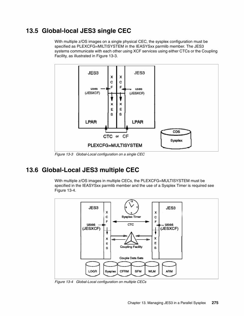
13.5 Global-local JES3 single CEC
With multiple z/OS images on a single physical CEC, the sysplex configuration must be specified as PLEXCFG=MILTISYSTEM in the IEASYSxx parmlib member. The JES3 systems communicate with each other using XCF services using either CTCs or the Coupling Facility, as illustrated in Figure 13-3.
Figure 13-3 Global-Local configuration on a single CEC
13.6 Global-Local JES3 multiple CEC
With multiple z/OS images in multiple CECs, the PLEXCFG=MULTISYSTEM must be specified in the IEASYSxx parmlib member and the use of a Sysplex Timer is required see Figure 13-4.
Figure 13-4 Global-Local configuration on multiple CECs
Chapter 13. Managing JES3 in a Parallel Sysplex 275

13.7 z/OS system failure actions for JES3
The following are actions related to JES3 if a z/OS system fails:
� If the z/OS system that failed was the JES3 global processor, we recommend that you bring that system back up as quickly as possible. You could change one of the JES3 local processors to be the JES3 global using dynamic system interchange (DSI). However, in some environments, this process is non-trivial, and might not even be possible. Whether or not you switch one of your JES3 local processors to be the global, you should not attempt to use Automatic Restart Manager to do cross-system restarts of any subsystems running on a JES3 global system.
� If the system that failed was a JES3 local processor, then after you are certain that the system has been partitioned out of the sysplex (as indicated by the IXC105I message SYSPLEX PARTITIONING HAS COMPLETED...), issue the command *START,main,FLUSH to ensure that those elements registered with Automatic Restart Manager can successfully restart on another JES3 local system.
13.8 Dynamic system interchange
Dynamic system interchange (DSI) is the backup facility to be used if a permanent machine or program failure occurs on the global, or if system reconfiguration is necessary for preventive maintenance.
DSI allows JES3 to continue operation by switching the global function to a local main in the same JES3 complex. If a failure occurs during DSI, try a hot start. A failure during connect processing could be the cause of the failure. If the failure recurs, a warm start is required.
The DSI procedure consists of a sequence of commands entered on either the old or the new global. Your systems programmer should have a DSI procedure tailored for your installation and have it updated to reflect any changes to your installation’s configuration.
13.9 Starting JES3 on the global processor
The types of starts and restarts for the global processor are:
� Cold start � Warm start � Warm start with analysis � Warm start to replace a spool data set � Warm start with analysis to replace a spool data set � Hot start with refresh � Hot start with refresh and analysis � Hot start � Hot start with analysis
You must use a cold start when starting JES3 for the first time. JES3 initialization statements are read as part of cold start, warm start, and hot start with refresh processing.
Important: Ensure that the old global's JES3 address space is no longer functioning when the new global is being initialized during the DSI process. This includes the JES3DLOG address space that might have been executing on the global z/OS system as well.
276 IBM z/OS Parallel Sysplex Operational Scenarios
If JES3 detects any error in the initialization statements, it prints an appropriate diagnostic message on the console or in the JES3OUT data set. JES3 ends processing if it cannot recover from the error.
13.10 Starting JES3 on a local processor
Use a local start to restart JES3 on a local main after a normal shutdown on the local, after JES3 ends because of a failure in either the local JES3 address space or z/OS. You must also start each local main after you perform a cold start or any type of warm start on the global or after you use a hot start to remove or reinstate a spool data set on the global processor. You can perform a local start any time the global is active.
You do not have to IPL the local main before you perform the local start unless one of the following is true:
� z/OS was shut down on the local main.
� z/OS was not previously started.
� z/OS failed on the local main.
� A cold start or any type of warm start was performed on the global processor.
13.11 JES3 networking with TCP/IP
Prior to z/OS V1R8, the network job entry (NJE) function in JES3 was limited to the binary synchronous (BSC) and system networking architecture (SNA) protocols. Both of these communication protocols require dependent hardware which is, or soon will be, out of service. There are several solutions that provide SNA connectivity over TCP/IP (such as Enterprise Extender). However, compared to a pure TCP/IP network, these solutions suffer from performance and interoperability problems, and are usually more difficult to maintain.
Starting with z/OS V1R8, JES3 provides support for NJE over TCP/IP. JES2 has been providing NJE over TCP/IP support since z/OS V1R7. VM (RSCS), VSE, and AS/400® have been providing NJE over TCP/IP support for several releases. JES3 on z/OS V1R8 is now able to communicate with JES2, VM, VSE, AS/400, or any other applicable component, using NJE over TCP/IP.
As TCP/IP becomes the standard for networking today, JES now implements NJE using the TCP/IP protocol.
To send data from one node to another using TCP/IP, a virtual circuit is established between the two nodes. The virtual circuit allows TCP/IP packets to be sent between the nodes. Each node is assigned an IP address.
The commands to start/stop network devices are similar to managing the SNA devices for NJE.
Figure 13-5 on page 278 displays a TCP/IP NJE configuration.
Chapter 13. Managing JES3 in a Parallel Sysplex 277
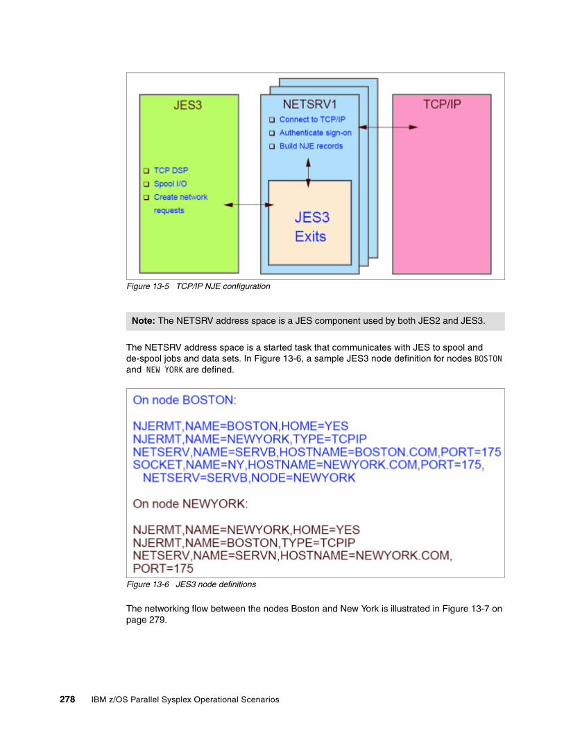
Figure 13-5 TCP/IP NJE configuration
The NETSRV address space is a started task that communicates with JES to spool and de-spool jobs and data sets. In Figure 13-6, a sample JES3 node definition for nodes BOSTON and NEW YORK are defined.
Figure 13-6 JES3 node definitions
The networking flow between the nodes Boston and New York is illustrated in Figure 13-7 on page 279.
Note: The NETSRV address space is a JES component used by both JES2 and JES3.
278 IBM z/OS Parallel Sysplex Operational Scenarios

Figure 13-7 Networking flow between nodes
13.11.1 JES3 TCP/IP NJE commands
This section discusses JES3 TCP/IP NJE commands and their function. Figure 13-8 shows the use of I NETSERV.
Figure 13-8 Inquire on NETSRV
Figure 13-9 shows how to alter the port used.
Figure 13-9 Altering the port used
Table 13-1 on page 280 lists useful commands for TCP/IP NJE and provides a brief description of their purpose.
Chapter 13. Managing JES3 in a Parallel Sysplex 279
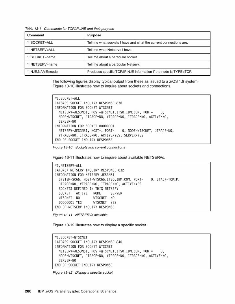
Table 13-1 Commands for TCP/IP JNE and their purpose
The following figures display typical output from these as issued to a z/OS 1.9 system. Figure 13-10 illustrates how to inquire about sockets and connections.
Figure 13-10 Sockets and current connections
Figure 13-11 illustrates how to inquire about available NETSERVs.
Figure 13-11 NETSERVs available
Figure 13-12 illustrates how to display a specific socket.
Figure 13-12 Display a specific socket
Command Purpose
*I,SOCKET=ALL Tell me what sockets I have and what the current connections are.
*I,NETSERV=ALL Tell me what Netservs I have.
*I,SOCKET=name Tell me about a particular socket.
*I,NETSERV=name Tell me about a particular Netserv.
*I,NJE,NAME=node Produces specific TCP/IP NJE information if the node is TYPE=TCP.
*I,SOCKET=ALL IAT8709 SOCKET INQUIRY RESPONSE 836 INFORMATION FOR SOCKET WTSCNET NETSERV=JES3NS1, HOST=WTSCNET.ITSO.IBM.COM, PORT= 0, NODE=WTSCNET, JTRACE=NO, VTRACE=NO, ITRACE=NO, ACTIVE=NO, SERVER=NO INFORMATION FOR SOCKET @0000001 NETSERV=JES3NS1, HOST=, PORT= 0, NODE=WTSCNET, JTRACE=NO, VTRACE=NO, ITRACE=NO, ACTIVE=YES, SERVER=YES END OF SOCKET INQUIRY RESPONSE
*I,NETSERV=ALL IAT8707 NETSERV INQUIRY RESPONSE 832 INFORMATION FOR NETSERV JES3NS1 SYSTEM=SC65, HOST=WTSC65.ITSO.IBM.COM, PORT= 0, STACK=TCPIP, JTRACE=NO, VTRACE=NO, ITRACE=NO, ACTIVE=YES SOCKETS DEFINED IN THIS NETSERV SOCKET ACTIVE NODE SERVER WTSCNET NO WTSCNET NO @0000001 YES WTSCNET YES END OF NETSERV INQUIRY RESPONSE
*I,SOCKET=WTSCNET IAT8709 SOCKET INQUIRY RESPONSE 840 INFORMATION FOR SOCKET WTSCNET NETSERV=JES3NS1, HOST=WTSCNET.ITSO.IBM.COM, PORT= 0, NODE=WTSCNET, JTRACE=NO, VTRACE=NO, ITRACE=NO, ACTIVE=NO, SERVER=NO END OF SOCKET INQUIRY RESPONSE
280 IBM z/OS Parallel Sysplex Operational Scenarios
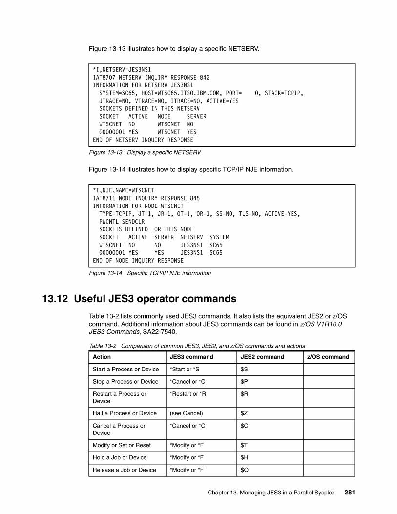
Figure 13-13 illustrates how to display a specific NETSERV.
Figure 13-13 Display a specific NETSERV
Figure 13-14 illustrates how to display specific TCP/IP NJE information.
Figure 13-14 Specific TCP/IP NJE information
13.12 Useful JES3 operator commands
Table 13-2 lists commonly used JES3 commands. It also lists the equivalent JES2 or z/OS command. Additional information about JES3 commands can be found in z/OS V1R10.0 JES3 Commands, SA22-7540.
Table 13-2 Comparison of common JES3, JES2, and z/OS commands and actions
*I,NETSERV=JES3NS1 IAT8707 NETSERV INQUIRY RESPONSE 842 INFORMATION FOR NETSERV JES3NS1 SYSTEM=SC65, HOST=WTSC65.ITSO.IBM.COM, PORT= 0, STACK=TCPIP, JTRACE=NO, VTRACE=NO, ITRACE=NO, ACTIVE=YES SOCKETS DEFINED IN THIS NETSERV SOCKET ACTIVE NODE SERVER WTSCNET NO WTSCNET NO @0000001 YES WTSCNET YES END OF NETSERV INQUIRY RESPONSE
*I,NJE,NAME=WTSCNET IAT8711 NODE INQUIRY RESPONSE 845 INFORMATION FOR NODE WTSCNET TYPE=TCPIP, JT=1, JR=1, OT=1, OR=1, SS=NO, TLS=NO, ACTIVE=YES, PWCNTL=SENDCLR SOCKETS DEFINED FOR THIS NODE SOCKET ACTIVE SERVER NETSERV SYSTEM WTSCNET NO NO JES3NS1 SC65 @0000001 YES YES JES3NS1 SC65 END OF NODE INQUIRY RESPONSE
Action JES3 command JES2 command z/OS command
Start a Process or Device *Start or *S $S
Stop a Process or Device *Cancel or *C $P
Restart a Process or Device
*Restart or *R $R
Halt a Process or Device (see Cancel) $Z
Cancel a Process or Device
*Cancel or *C $C
Modify or Set or Reset *Modify or *F $T
Hold a Job or Device *Modify or *F $H
Release a Job or Device *Modify or *F $O
Chapter 13. Managing JES3 in a Parallel Sysplex 281
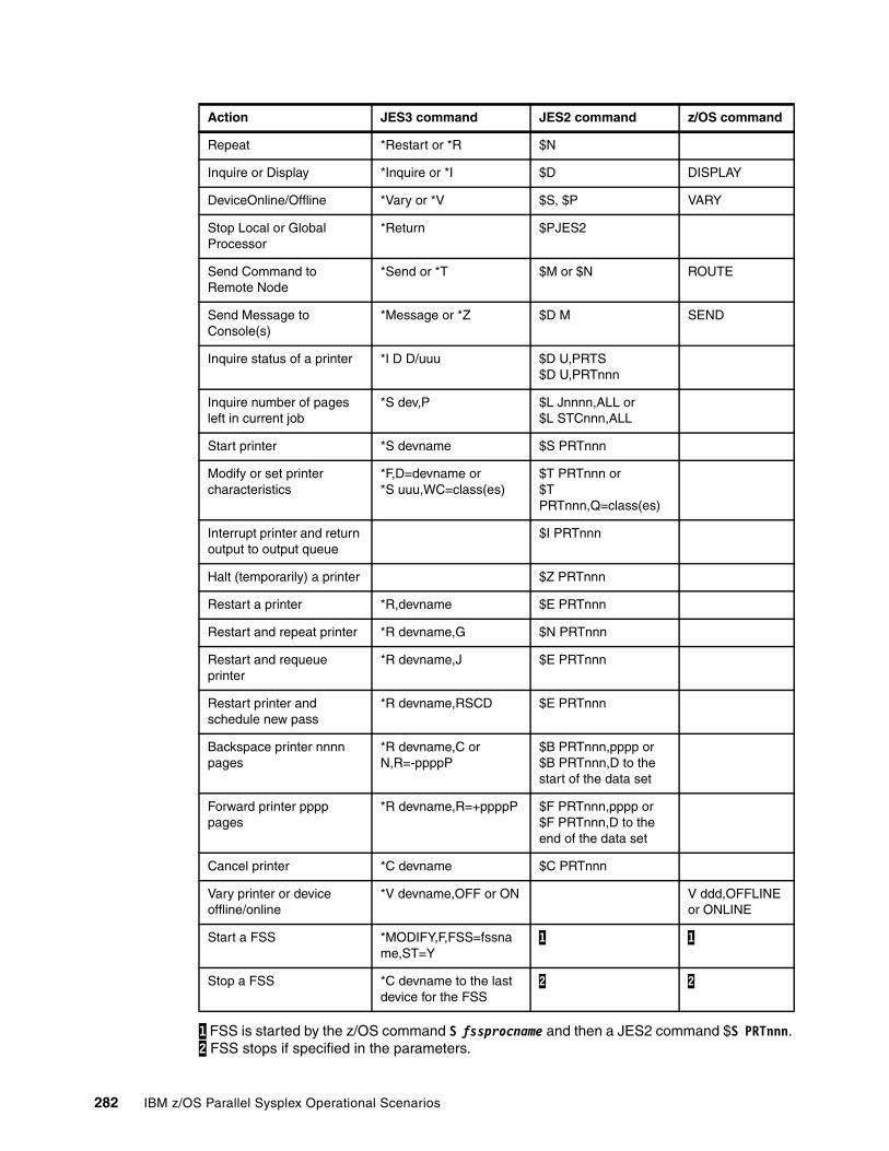
1 FSS is started by the z/OS command S fssprocname and then a JES2 command $S PRTnnn. 2 FSS stops if specified in the parameters.
Repeat *Restart or *R $N
Inquire or Display *Inquire or *I $D DISPLAY
DeviceOnline/Offline *Vary or *V $S, $P VARY
Stop Local or Global Processor
*Return $PJES2
Send Command to Remote Node
*Send or *T $M or $N ROUTE
Send Message to Console(s)
*Message or *Z $D M SEND
Inquire status of a printer *I D D/uuu $D U,PRTS$D U,PRTnnn
Inquire number of pages left in current job
*S dev,P $L Jnnnn,ALL or$L STCnnn,ALL
Start printer *S devname $S PRTnnn
Modify or set printer characteristics
*F,D=devname or *S uuu,WC=class(es)
$T PRTnnn or$T PRTnnn,Q=class(es)
Interrupt printer and return output to output queue
$I PRTnnn
Halt (temporarily) a printer $Z PRTnnn
Restart a printer *R,devname $E PRTnnn
Restart and repeat printer *R devname,G $N PRTnnn
Restart and requeue printer
*R devname,J $E PRTnnn
Restart printer and schedule new pass
*R devname,RSCD $E PRTnnn
Backspace printer nnnn pages
*R devname,C or N,R=-ppppP
$B PRTnnn,pppp or$B PRTnnn,D to the start of the data set
Forward printer pppp pages
*R devname,R=+ppppP $F PRTnnn,pppp or$F PRTnnn,D to the end of the data set
Cancel printer *C devname $C PRTnnn
Vary printer or device offline/online
*V devname,OFF or ON V ddd,OFFLINE or ONLINE
Start a FSS *MODIFY,F,FSS=fssname,ST=Y
1 1
Stop a FSS *C devname to the last device for the FSS
2 2
Action JES3 command JES2 command z/OS command
282 IBM z/OS Parallel Sysplex Operational Scenarios

Chapter 14. Managing consoles in a Parallel Sysplex
This chapter provides information about console operations in a Parallel Sysplex environment, including;
� Console management
� Operating from the HMC
� Console buffer shortages
� Console command routing
� Message Flood Automation (MFA)
� z/OS Management Console
14
© Copyright IBM Corp. 2009. All rights reserved. 283

14.1 Introduction to managing consoles in a Parallel Sysplex
Historically, operators of a z/OS image have received messages and entered commands from multiple console support (MCS) consoles. Today, with console support available across multiple systems, a sysplex comprised of many z/OS images can be operated from a single console. Because the operator has a single point of control for all images, MCS often refers to multisystem console support.
In a sysplex, MCS consoles can:
� Be attached to any system
� Receive messages from any system in the sysplex
� Route commands to any system in the sysplex
Therefore, the following considerations apply when defining MCS consoles in this environment:
� There is no requirement that each system have consoles attached.
� A sysplex, which can be up to 32 systems, can be operated from a single console.
� Multiple consoles can have master command authority.
� There is no need to define a master console, or define alternate console groups for console switch operation.
In z/OS V1.8, the single master console was eliminated, which removed a single point of failure. The console switch function was also removed, which removed a potential point of failure because you can now define more than two consoles with master console authority. This is discussed in more detail in 14.2.1, “Sysplex master console” on page 286.
There are four types of operator consoles available for use in a sysplex:
MCS MCS consoles are display devices that are attached to a z/OS system to provide communication between operators and z/OS. MCS consoles are defined to a local non-SNA control unit (for example an OSA Integrated Console Controller, or 2074). Currently you can define a maximum of 99 MCS consoles for the entire Parallel Sysplex. In a future release of z/OS, IBM plans to increase the maximum number of MCS and SNA MCS (SMCS) consoles that can be defined and active in a configuration from 99 per sysplex to 99 per system in the sysplex.
SMCS SNA MCS consoles use z/OS Communications Server to communicate with the system and may be remotely attached to the system. SMCS consoles are only available for use when the z/OS Communications Server is active. See 14.2.3, “SNA MCS consoles” on page 287 for more details.
EMCS Extended MCS consoles are defined and activated by authorized programs acting as operators. An extended MCS console is actually a program that acts as a console. See 14.2.2, “Extended MCS consoles” on page 286 for more details.
Hardware In this context, the term hardware (or system) consoles refers to the interface provided by the Hardware Management Console (HMC) on an IBM System z processor. It is referred to as SYSCONS. See 14.4, “Operating z/OS from the HMC” on page 291 for more details.
284 IBM z/OS Parallel Sysplex Operational Scenarios
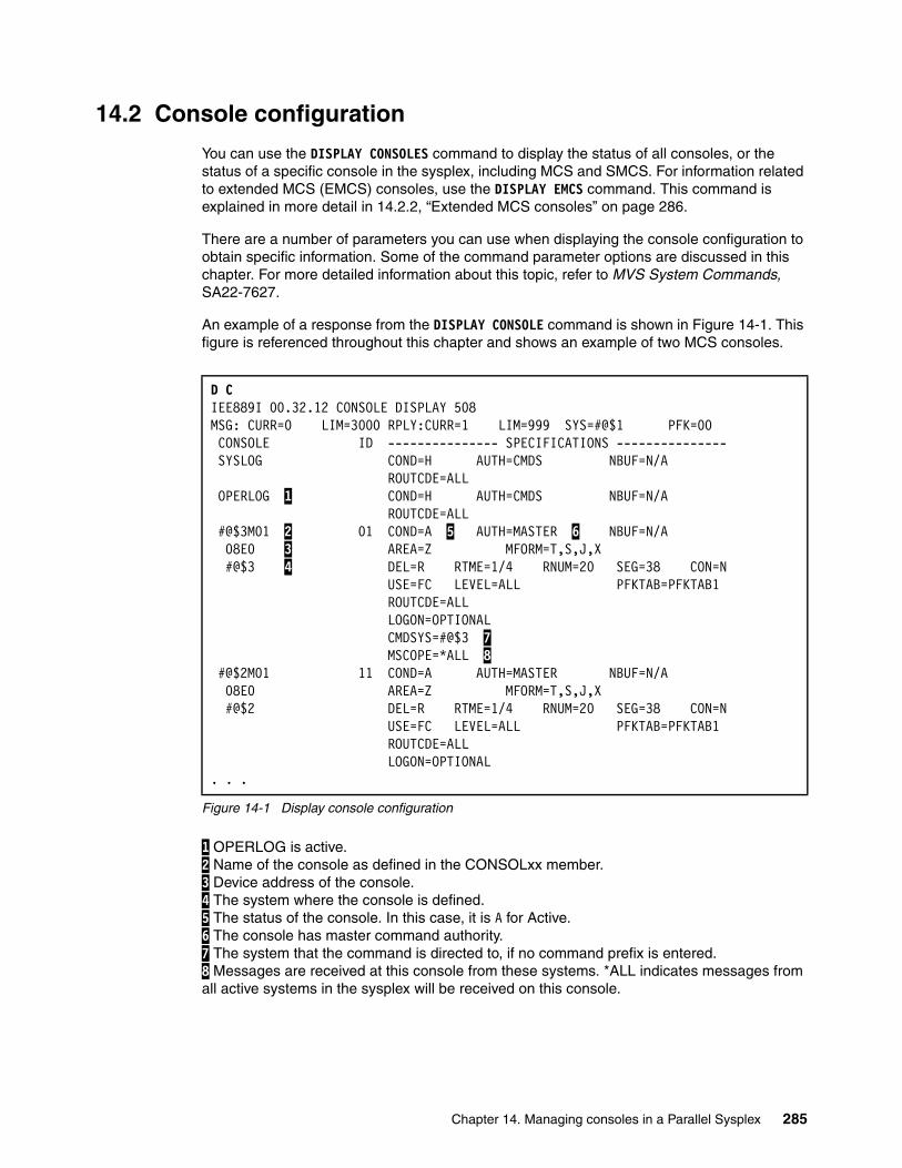
14.2 Console configuration
You can use the DISPLAY CONSOLES command to display the status of all consoles, or the status of a specific console in the sysplex, including MCS and SMCS. For information related to extended MCS (EMCS) consoles, use the DISPLAY EMCS command. This command is explained in more detail in 14.2.2, “Extended MCS consoles” on page 286.
There are a number of parameters you can use when displaying the console configuration to obtain specific information. Some of the command parameter options are discussed in this chapter. For more detailed information about this topic, refer to MVS System Commands, SA22-7627.
An example of a response from the DISPLAY CONSOLE command is shown in Figure 14-1. This figure is referenced throughout this chapter and shows an example of two MCS consoles.
Figure 14-1 Display console configuration
1 OPERLOG is active. 2 Name of the console as defined in the CONSOLxx member. 3 Device address of the console. 4 The system where the console is defined. 5 The status of the console. In this case, it is A for Active. 6 The console has master command authority. 7 The system that the command is directed to, if no command prefix is entered. 8 Messages are received at this console from these systems. *ALL indicates messages from all active systems in the sysplex will be received on this console.
D C IEE889I 00.32.12 CONSOLE DISPLAY 508 MSG: CURR=0 LIM=3000 RPLY:CURR=1 LIM=999 SYS=#@$1 PFK=00 CONSOLE ID --------------- SPECIFICATIONS --------------- SYSLOG COND=H AUTH=CMDS NBUF=N/A ROUTCDE=ALL OPERLOG 1 COND=H AUTH=CMDS NBUF=N/A ROUTCDE=ALL #@$3M01 2 01 COND=A 5 AUTH=MASTER 6 NBUF=N/A 08E0 3 AREA=Z MFORM=T,S,J,X #@$3 4 DEL=R RTME=1/4 RNUM=20 SEG=38 CON=N USE=FC LEVEL=ALL PFKTAB=PFKTAB1 ROUTCDE=ALL LOGON=OPTIONAL CMDSYS=#@$3 7 MSCOPE=*ALL 8 #@$2M01 11 COND=A AUTH=MASTER NBUF=N/A 08E0 AREA=Z MFORM=T,S,J,X #@$2 DEL=R RTME=1/4 RNUM=20 SEG=38 CON=N USE=FC LEVEL=ALL PFKTAB=PFKTAB1 ROUTCDE=ALL LOGON=OPTIONAL . . .
Chapter 14. Managing consoles in a Parallel Sysplex 285
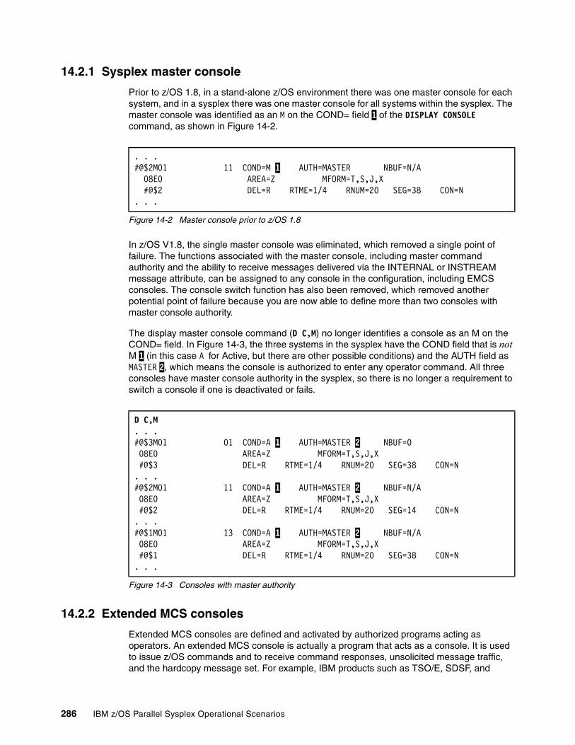
14.2.1 Sysplex master console
Prior to z/OS 1.8, in a stand-alone z/OS environment there was one master console for each system, and in a sysplex there was one master console for all systems within the sysplex. The master console was identified as an M on the COND= field 1 of the DISPLAY CONSOLE command, as shown in Figure 14-2.
Figure 14-2 Master console prior to z/OS 1.8
In z/OS V1.8, the single master console was eliminated, which removed a single point of failure. The functions associated with the master console, including master command authority and the ability to receive messages delivered via the INTERNAL or INSTREAM message attribute, can be assigned to any console in the configuration, including EMCS consoles. The console switch function has also been removed, which removed another potential point of failure because you are now able to define more than two consoles with master console authority.
The display master console command (D C,M) no longer identifies a console as an M on the COND= field. In Figure 14-3, the three systems in the sysplex have the COND field that is not M 1 (in this case A for Active, but there are other possible conditions) and the AUTH field as MASTER 2, which means the console is authorized to enter any operator command. All three consoles have master console authority in the sysplex, so there is no longer a requirement to switch a console if one is deactivated or fails.
Figure 14-3 Consoles with master authority
14.2.2 Extended MCS consoles
Extended MCS consoles are defined and activated by authorized programs acting as operators. An extended MCS console is actually a program that acts as a console. It is used to issue z/OS commands and to receive command responses, unsolicited message traffic, and the hardcopy message set. For example, IBM products such as TSO/E, SDSF, and
. . .#@$2M01 11 COND=M 1 AUTH=MASTER NBUF=N/A 08E0 AREA=Z MFORM=T,S,J,X #@$2 DEL=R RTME=1/4 RNUM=20 SEG=38 CON=N . . .
D C,M. . .#@$3M01 01 COND=A 1 AUTH=MASTER 2 NBUF=0 08E0 AREA=Z MFORM=T,S,J,X #@$3 DEL=R RTME=1/4 RNUM=20 SEG=38 CON=N . . .#@$2M01 11 COND=A 1 AUTH=MASTER 2 NBUF=N/A 08E0 AREA=Z MFORM=T,S,J,X #@$2 DEL=R RTME=1/4 RNUM=20 SEG=14 CON=N . . .#@$1M01 13 COND=A 1 AUTH=MASTER 2 NBUF=N/A 08E0 AREA=Z MFORM=T,S,J,X #@$1 DEL=R RTME=1/4 RNUM=20 SEG=38 CON=N . . .
286 IBM z/OS Parallel Sysplex Operational Scenarios
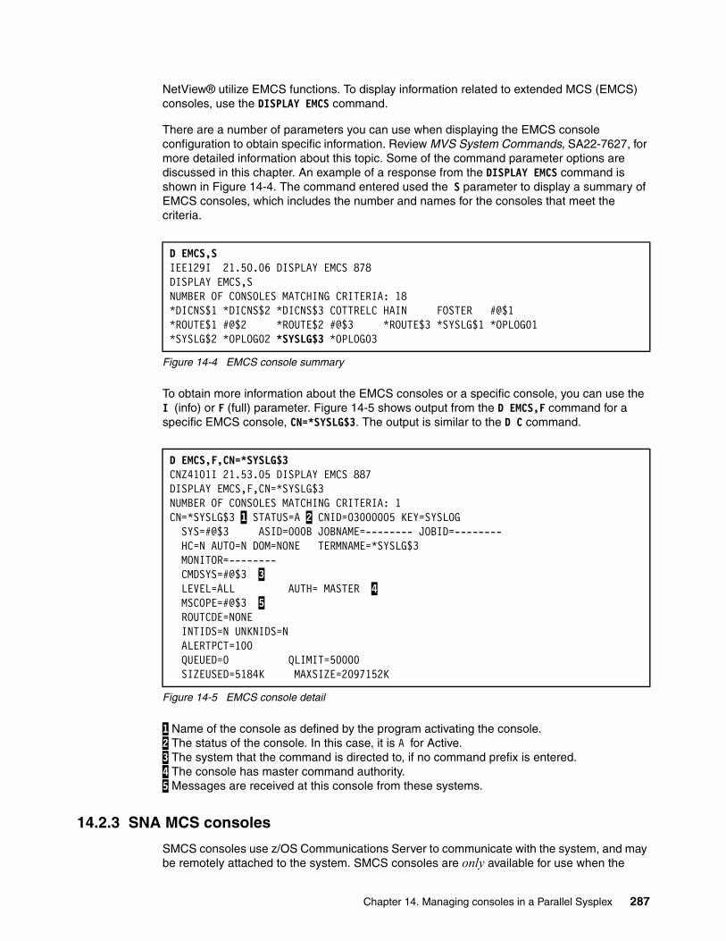
NetView® utilize EMCS functions. To display information related to extended MCS (EMCS) consoles, use the DISPLAY EMCS command.
There are a number of parameters you can use when displaying the EMCS console configuration to obtain specific information. Review MVS System Commands, SA22-7627, for more detailed information about this topic. Some of the command parameter options are discussed in this chapter. An example of a response from the DISPLAY EMCS command is shown in Figure 14-4. The command entered used the S parameter to display a summary of EMCS consoles, which includes the number and names for the consoles that meet the criteria.
Figure 14-4 EMCS console summary
To obtain more information about the EMCS consoles or a specific console, you can use the I (info) or F (full) parameter. Figure 14-5 shows output from the D EMCS,F command for a specific EMCS console, CN=*SYSLG$3. The output is similar to the D C command.
Figure 14-5 EMCS console detail
1 Name of the console as defined by the program activating the console. 2 The status of the console. In this case, it is A for Active. 3 The system that the command is directed to, if no command prefix is entered. 4 The console has master command authority. 5 Messages are received at this console from these systems.
14.2.3 SNA MCS consoles
SMCS consoles use z/OS Communications Server to communicate with the system, and may be remotely attached to the system. SMCS consoles are only available for use when the
D EMCS,S IEE129I 21.50.06 DISPLAY EMCS 878 DISPLAY EMCS,S NUMBER OF CONSOLES MATCHING CRITERIA: 18 *DICNS$1 *DICNS$2 *DICNS$3 COTTRELC HAIN FOSTER #@$1 *ROUTE$1 #@$2 *ROUTE$2 #@$3 *ROUTE$3 *SYSLG$1 *OPLOG01*SYSLG$2 *OPLOG02 *SYSLG$3 *OPLOG03
D EMCS,F,CN=*SYSLG$3 CNZ4101I 21.53.05 DISPLAY EMCS 887 DISPLAY EMCS,F,CN=*SYSLG$3 NUMBER OF CONSOLES MATCHING CRITERIA: 1 CN=*SYSLG$3 1 STATUS=A 2 CNID=03000005 KEY=SYSLOG SYS=#@$3 ASID=000B JOBNAME=-------- JOBID=-------- HC=N AUTO=N DOM=NONE TERMNAME=*SYSLG$3 MONITOR=-------- CMDSYS=#@$3 3 LEVEL=ALL AUTH= MASTER 4 MSCOPE=#@$3 5 ROUTCDE=NONE INTIDS=N UNKNIDS=N ALERTPCT=100 QUEUED=0 QLIMIT=50000 SIZEUSED=5184K MAXSIZE=2097152K
Chapter 14. Managing consoles in a Parallel Sysplex 287
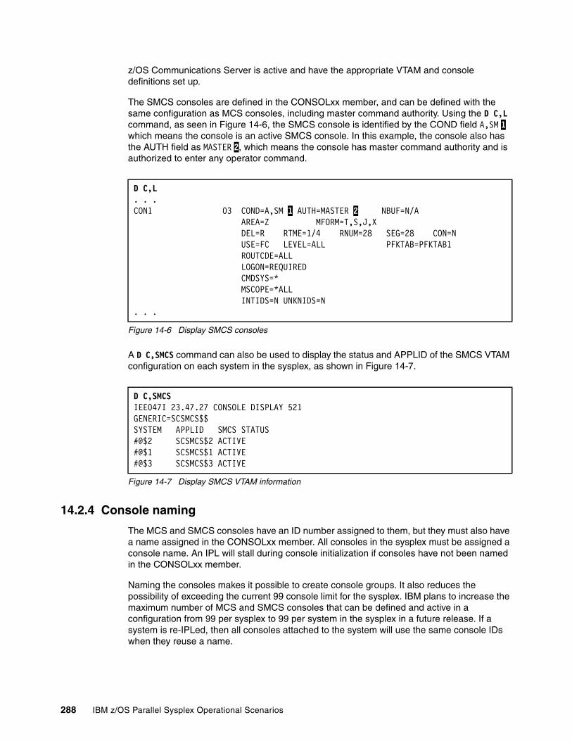
z/OS Communications Server is active and have the appropriate VTAM and console definitions set up.
The SMCS consoles are defined in the CONSOLxx member, and can be defined with the same configuration as MCS consoles, including master command authority. Using the D C,L command, as seen in Figure 14-6, the SMCS console is identified by the COND field A,SM 1 which means the console is an active SMCS console. In this example, the console also has the AUTH field as MASTER 2, which means the console has master command authority and is authorized to enter any operator command.
Figure 14-6 Display SMCS consoles
A D C,SMCS command can also be used to display the status and APPLID of the SMCS VTAM configuration on each system in the sysplex, as shown in Figure 14-7.
Figure 14-7 Display SMCS VTAM information
14.2.4 Console naming
The MCS and SMCS consoles have an ID number assigned to them, but they must also have a name assigned in the CONSOLxx member. All consoles in the sysplex must be assigned a console name. An IPL will stall during console initialization if consoles have not been named in the CONSOLxx member.
Naming the consoles makes it possible to create console groups. It also reduces the possibility of exceeding the current 99 console limit for the sysplex. IBM plans to increase the maximum number of MCS and SMCS consoles that can be defined and active in a configuration from 99 per sysplex to 99 per system in the sysplex in a future release. If a system is re-IPLed, then all consoles attached to the system will use the same console IDs when they reuse a name.
D C,L. . .CON1 03 COND=A,SM 1 AUTH=MASTER 2 NBUF=N/A AREA=Z MFORM=T,S,J,X DEL=R RTME=1/4 RNUM=28 SEG=28 CON=N USE=FC LEVEL=ALL PFKTAB=PFKTAB1 ROUTCDE=ALL LOGON=REQUIRED CMDSYS=* MSCOPE=*ALL INTIDS=N UNKNIDS=N . . .
D C,SMCS IEE047I 23.47.27 CONSOLE DISPLAY 521GENERIC=SCSMCS$$ SYSTEM APPLID SMCS STATUS #@$2 SCSMCS$2 ACTIVE #@$1 SCSMCS$1 ACTIVE #@$3 SCSMCS$3 ACTIVE
288 IBM z/OS Parallel Sysplex Operational Scenarios
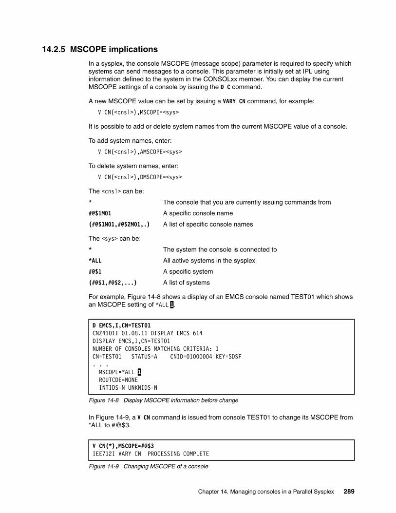
14.2.5 MSCOPE implications
In a sysplex, the console MSCOPE (message scope) parameter is required to specify which systems can send messages to a console. This parameter is initially set at IPL using information defined to the system in the CONSOLxx member. You can display the current MSCOPE settings of a console by issuing the D C command.
A new MSCOPE value can be set by issuing a VARY CN command, for example:
V CN(<cnsl>),MSCOPE=<sys>
It is possible to add or delete system names from the current MSCOPE value of a console.
To add system names, enter:
V CN(<cnsl>),AMSCOPE=<sys>
To delete system names, enter:
V CN(<cnsl>),DMSCOPE=<sys>
The <cnsl> can be:
* The console that you are currently issuing commands from
#@$1M01 A specific console name
(#@$1M01,#@$2M01,.) A list of specific console names
The <sys> can be:
* The system the console is connected to
*ALL All active systems in the sysplex
#@$1 A specific system
(#@$1,#@$2,...) A list of systems
For example, Figure 14-8 shows a display of an EMCS console named TEST01 which shows an MSCOPE setting of *ALL 1.
Figure 14-8 Display MSCOPE information before change
In Figure 14-9, a V CN command is issued from console TEST01 to change its MSCOPE from *ALL to #@$3.
Figure 14-9 Changing MSCOPE of a console
D EMCS,I,CN=TEST01 CNZ4101I 01.08.11 DISPLAY EMCS 614 DISPLAY EMCS,I,CN=TEST01 NUMBER OF CONSOLES MATCHING CRITERIA: 1 CN=TEST01 STATUS=A CNID=01000004 KEY=SDSF . . .
MSCOPE=*ALL 1 ROUTCDE=NONE INTIDS=N UNKNIDS=N
V CN(*),MSCOPE=#@$3 IEE712I VARY CN PROCESSING COMPLETE
Chapter 14. Managing consoles in a Parallel Sysplex 289
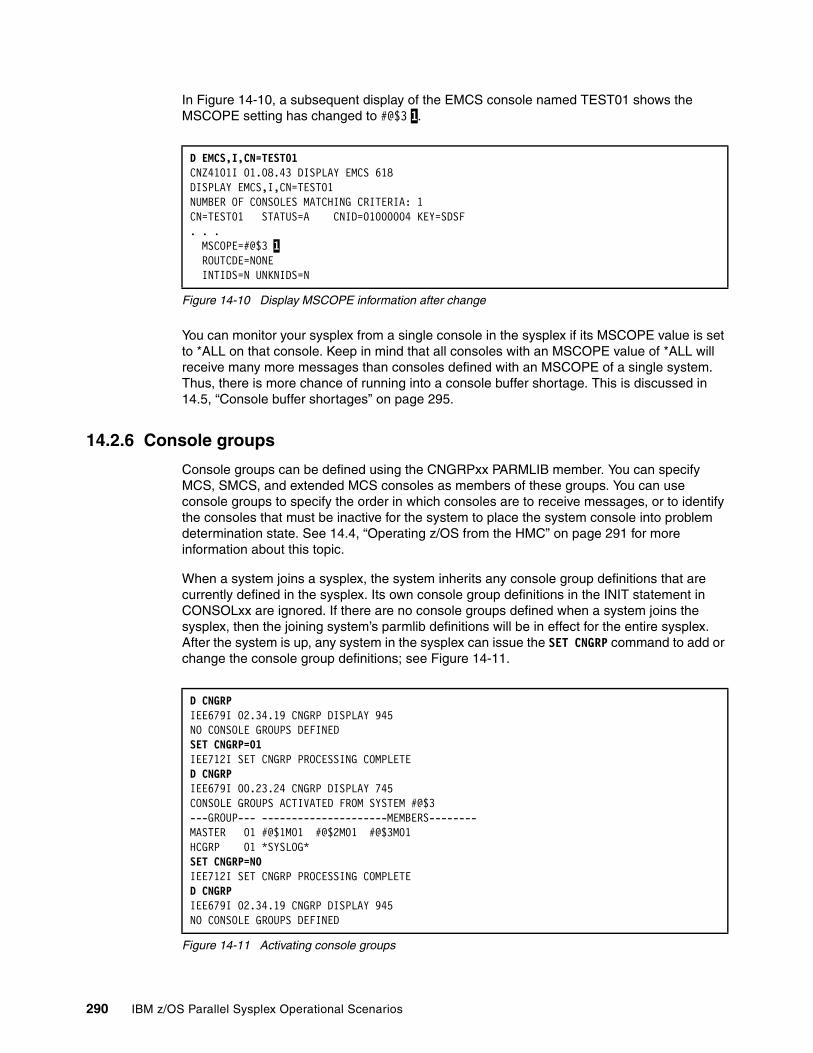
In Figure 14-10, a subsequent display of the EMCS console named TEST01 shows the MSCOPE setting has changed to #@$3 1.
Figure 14-10 Display MSCOPE information after change
You can monitor your sysplex from a single console in the sysplex if its MSCOPE value is set to *ALL on that console. Keep in mind that all consoles with an MSCOPE value of *ALL will receive many more messages than consoles defined with an MSCOPE of a single system. Thus, there is more chance of running into a console buffer shortage. This is discussed in 14.5, “Console buffer shortages” on page 295.
14.2.6 Console groups
Console groups can be defined using the CNGRPxx PARMLIB member. You can specify MCS, SMCS, and extended MCS consoles as members of these groups. You can use console groups to specify the order in which consoles are to receive messages, or to identify the consoles that must be inactive for the system to place the system console into problem determination state. See 14.4, “Operating z/OS from the HMC” on page 291 for more information about this topic.
When a system joins a sysplex, the system inherits any console group definitions that are currently defined in the sysplex. Its own console group definitions in the INIT statement in CONSOLxx are ignored. If there are no console groups defined when a system joins the sysplex, then the joining system’s parmlib definitions will be in effect for the entire sysplex. After the system is up, any system in the sysplex can issue the SET CNGRP command to add or change the console group definitions; see Figure 14-11.
Figure 14-11 Activating console groups
D EMCS,I,CN=TEST01 CNZ4101I 01.08.43 DISPLAY EMCS 618 DISPLAY EMCS,I,CN=TEST01 NUMBER OF CONSOLES MATCHING CRITERIA: 1 CN=TEST01 STATUS=A CNID=01000004 KEY=SDSF . . .MSCOPE=#@$3 1
ROUTCDE=NONE INTIDS=N UNKNIDS=N
D CNGRP IEE679I 02.34.19 CNGRP DISPLAY 945NO CONSOLE GROUPS DEFINED SET CNGRP=01 IEE712I SET CNGRP PROCESSING COMPLETE D CNGRP IEE679I 00.23.24 CNGRP DISPLAY 745 CONSOLE GROUPS ACTIVATED FROM SYSTEM #@$3 ---GROUP--- ---------------------MEMBERS--------MASTER 01 #@$1M01 #@$2M01 #@$3M01 HCGRP 01 *SYSLOG* SET CNGRP=NO IEE712I SET CNGRP PROCESSING COMPLETED CNGRP IEE679I 02.34.19 CNGRP DISPLAY 945 NO CONSOLE GROUPS DEFINED
290 IBM z/OS Parallel Sysplex Operational Scenarios
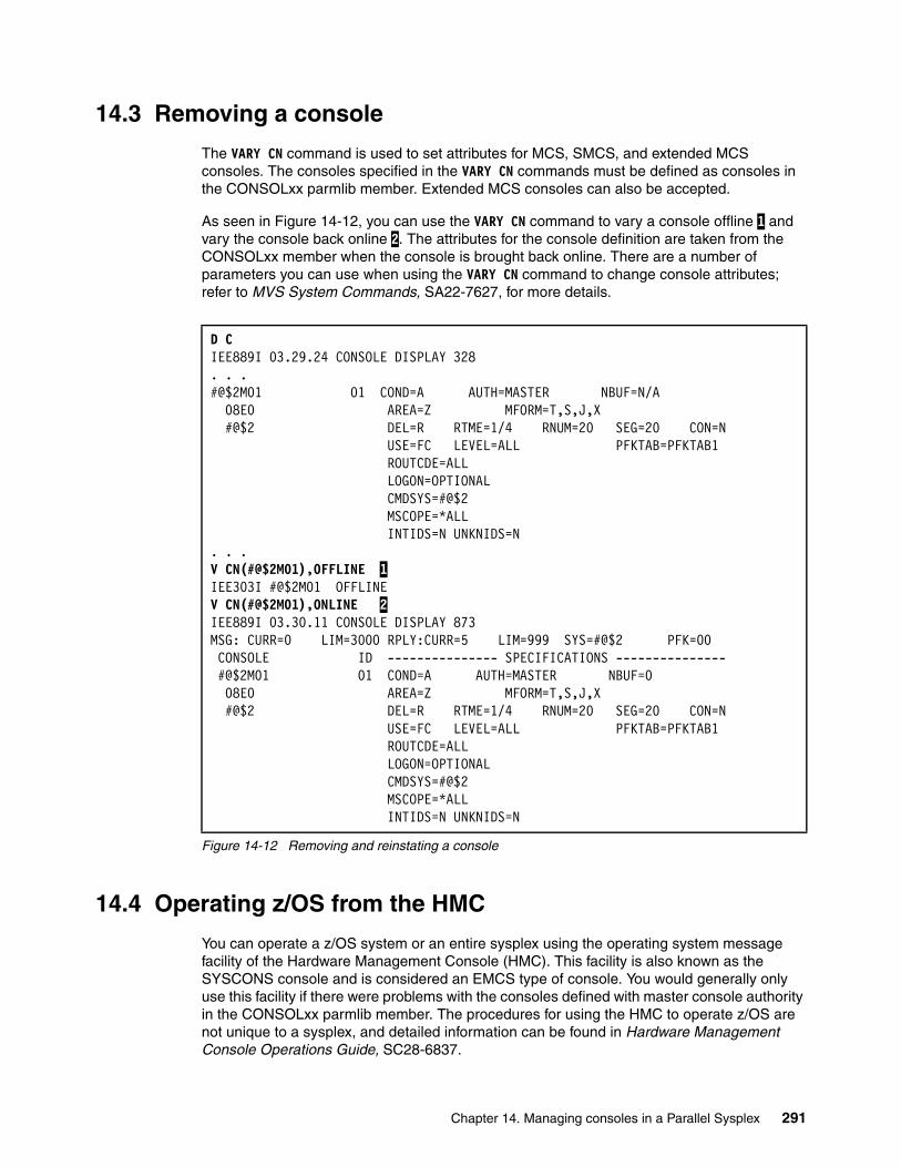
14.3 Removing a console
The VARY CN command is used to set attributes for MCS, SMCS, and extended MCS consoles. The consoles specified in the VARY CN commands must be defined as consoles in the CONSOLxx parmlib member. Extended MCS consoles can also be accepted.
As seen in Figure 14-12, you can use the VARY CN command to vary a console offline 1 and vary the console back online 2. The attributes for the console definition are taken from the CONSOLxx member when the console is brought back online. There are a number of parameters you can use when using the VARY CN command to change console attributes; refer to MVS System Commands, SA22-7627, for more details.
Figure 14-12 Removing and reinstating a console
14.4 Operating z/OS from the HMC
You can operate a z/OS system or an entire sysplex using the operating system message facility of the Hardware Management Console (HMC). This facility is also known as the SYSCONS console and is considered an EMCS type of console. You would generally only use this facility if there were problems with the consoles defined with master console authority in the CONSOLxx parmlib member. The procedures for using the HMC to operate z/OS are not unique to a sysplex, and detailed information can be found in Hardware Management Console Operations Guide, SC28-6837.
D C IEE889I 03.29.24 CONSOLE DISPLAY 328 . . .#@$2M01 01 COND=A AUTH=MASTER NBUF=N/A 08E0 AREA=Z MFORM=T,S,J,X #@$2 DEL=R RTME=1/4 RNUM=20 SEG=20 CON=N USE=FC LEVEL=ALL PFKTAB=PFKTAB1 ROUTCDE=ALL LOGON=OPTIONAL CMDSYS=#@$2 MSCOPE=*ALL INTIDS=N UNKNIDS=N . . .V CN(#@$2M01),OFFLINE 1 IEE303I #@$2M01 OFFLINEV CN(#@$2M01),ONLINE 2 IEE889I 03.30.11 CONSOLE DISPLAY 873 MSG: CURR=0 LIM=3000 RPLY:CURR=5 LIM=999 SYS=#@$2 PFK=00 CONSOLE ID --------------- SPECIFICATIONS --------------- #@$2M01 01 COND=A AUTH=MASTER NBUF=0 08E0 AREA=Z MFORM=T,S,J,X #@$2 DEL=R RTME=1/4 RNUM=20 SEG=20 CON=N USE=FC LEVEL=ALL PFKTAB=PFKTAB1 ROUTCDE=ALL LOGON=OPTIONAL CMDSYS=#@$2 MSCOPE=*ALL INTIDS=N UNKNIDS=N
Chapter 14. Managing consoles in a Parallel Sysplex 291
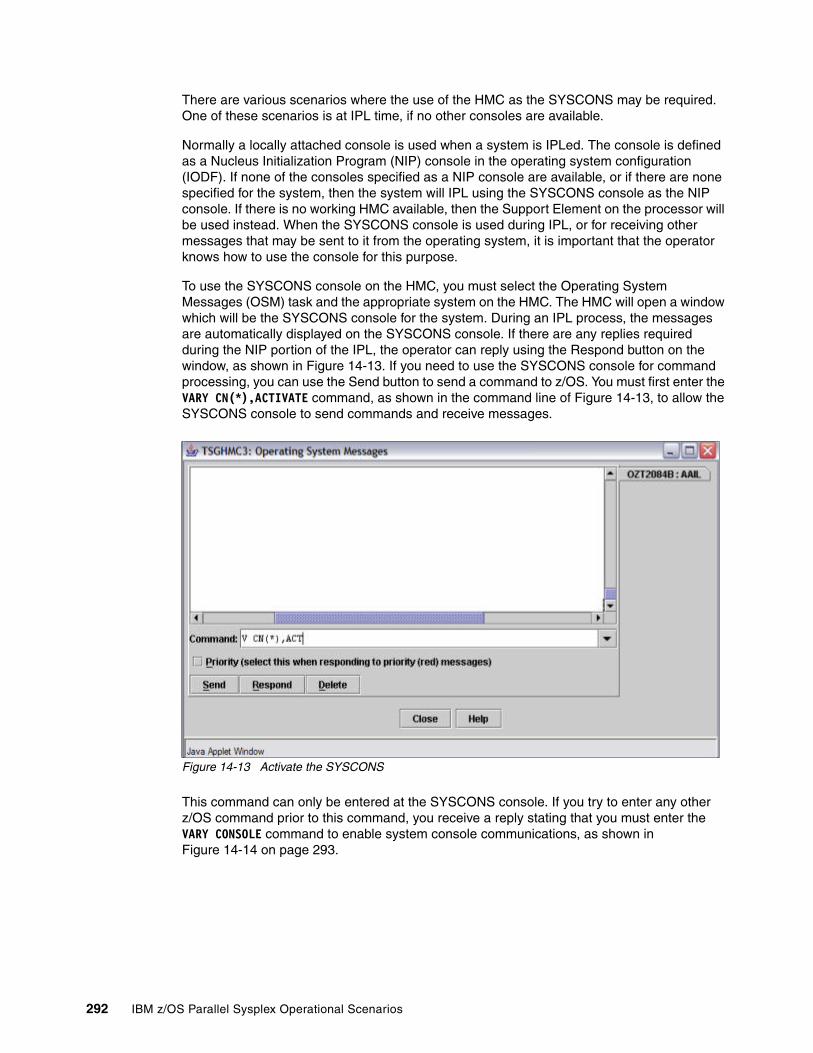
There are various scenarios where the use of the HMC as the SYSCONS may be required. One of these scenarios is at IPL time, if no other consoles are available.
Normally a locally attached console is used when a system is IPLed. The console is defined as a Nucleus Initialization Program (NIP) console in the operating system configuration (IODF). If none of the consoles specified as a NIP console are available, or if there are none specified for the system, then the system will IPL using the SYSCONS console as the NIP console. If there is no working HMC available, then the Support Element on the processor will be used instead. When the SYSCONS console is used during IPL, or for receiving other messages that may be sent to it from the operating system, it is important that the operator knows how to use the console for this purpose.
To use the SYSCONS console on the HMC, you must select the Operating System Messages (OSM) task and the appropriate system on the HMC. The HMC will open a window which will be the SYSCONS console for the system. During an IPL process, the messages are automatically displayed on the SYSCONS console. If there are any replies required during the NIP portion of the IPL, the operator can reply using the Respond button on the window, as shown in Figure 14-13. If you need to use the SYSCONS console for command processing, you can use the Send button to send a command to z/OS. You must first enter the VARY CN(*),ACTIVATE command, as shown in the command line of Figure 14-13, to allow the SYSCONS console to send commands and receive messages.
Figure 14-13 Activate the SYSCONS
This command can only be entered at the SYSCONS console. If you try to enter any other z/OS command prior to this command, you receive a reply stating that you must enter the VARY CONSOLE command to enable system console communications, as shown in Figure 14-14 on page 293.
292 IBM z/OS Parallel Sysplex Operational Scenarios

Figure 14-14 Command rejected
As a result of entering this command, and if z/OS is able to establish communication with the SYSCONS console, there is a response to indicate that the vary processing is complete, as shown in Figure 14-15.
Figure 14-15 Console activation complete
Messages are now displayed from systems as specified in the MSCOPE parameter for the SYSCONS. Also, almost any z/OS command can now be entered, with a few restrictions. If there is no response to the command, it may indicate that the system is not active, or the interface between z/OS and the Support Element (SE) is not working. There is also the possibility that the ROUTCDE setting on the SYSCONS is set to NONE. You can check this
Chapter 14. Managing consoles in a Parallel Sysplex 293
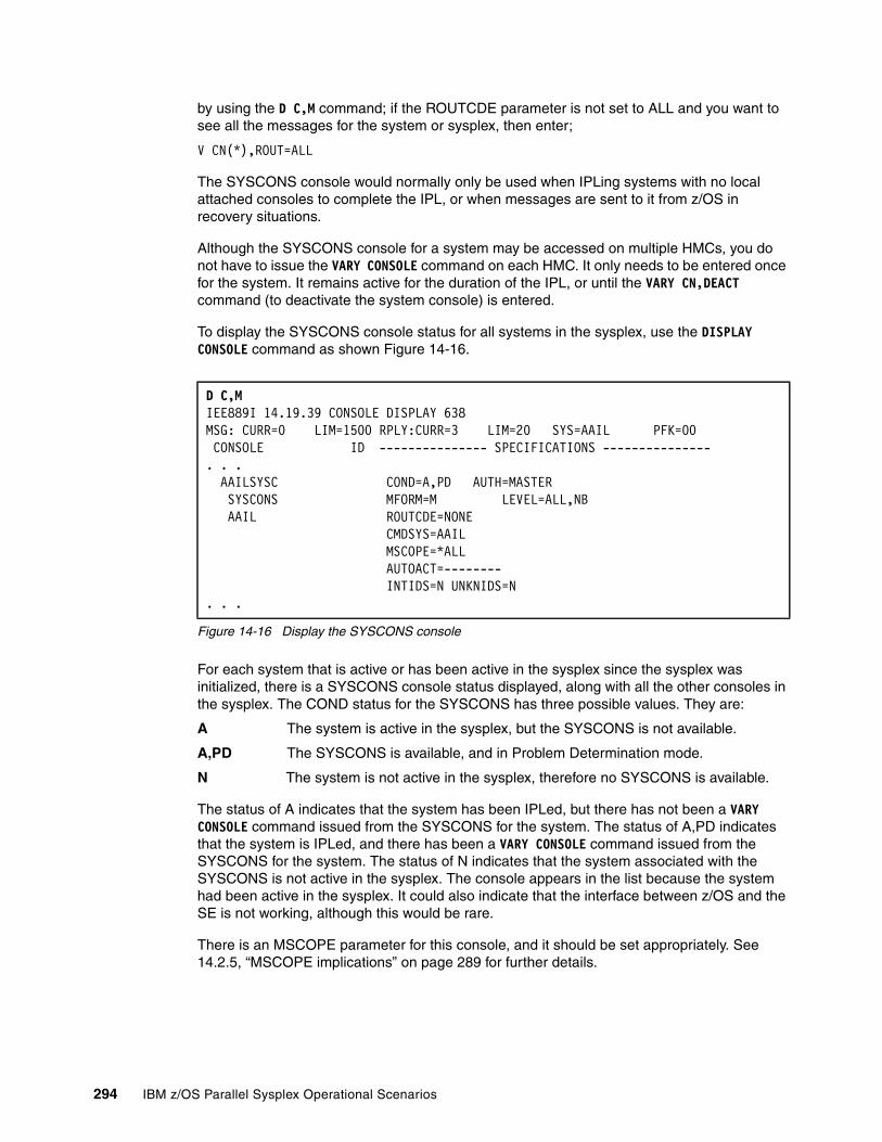
by using the D C,M command; if the ROUTCDE parameter is not set to ALL and you want to see all the messages for the system or sysplex, then enter;
V CN(*),ROUT=ALL
The SYSCONS console would normally only be used when IPLing systems with no local attached consoles to complete the IPL, or when messages are sent to it from z/OS in recovery situations.
Although the SYSCONS console for a system may be accessed on multiple HMCs, you do not have to issue the VARY CONSOLE command on each HMC. It only needs to be entered once for the system. It remains active for the duration of the IPL, or until the VARY CN,DEACT command (to deactivate the system console) is entered.
To display the SYSCONS console status for all systems in the sysplex, use the DISPLAY CONSOLE command as shown Figure 14-16.
Figure 14-16 Display the SYSCONS console
For each system that is active or has been active in the sysplex since the sysplex was initialized, there is a SYSCONS console status displayed, along with all the other consoles in the sysplex. The COND status for the SYSCONS has three possible values. They are:
A The system is active in the sysplex, but the SYSCONS is not available.
A,PD The SYSCONS is available, and in Problem Determination mode.
N The system is not active in the sysplex, therefore no SYSCONS is available.
The status of A indicates that the system has been IPLed, but there has not been a VARY CONSOLE command issued from the SYSCONS for the system. The status of A,PD indicates that the system is IPLed, and there has been a VARY CONSOLE command issued from the SYSCONS for the system. The status of N indicates that the system associated with the SYSCONS is not active in the sysplex. The console appears in the list because the system had been active in the sysplex. It could also indicate that the interface between z/OS and the SE is not working, although this would be rare.
There is an MSCOPE parameter for this console, and it should be set appropriately. See 14.2.5, “MSCOPE implications” on page 289 for further details.
D C,M IEE889I 14.19.39 CONSOLE DISPLAY 638 MSG: CURR=0 LIM=1500 RPLY:CURR=3 LIM=20 SYS=AAIL PFK=00 CONSOLE ID --------------- SPECIFICATIONS ---------------. . .
AAILSYSC COND=A,PD AUTH=MASTER SYSCONS MFORM=M LEVEL=ALL,NB AAIL ROUTCDE=NONE CMDSYS=AAIL MSCOPE=*ALL AUTOACT=-------- INTIDS=N UNKNIDS=N . . .
294 IBM z/OS Parallel Sysplex Operational Scenarios
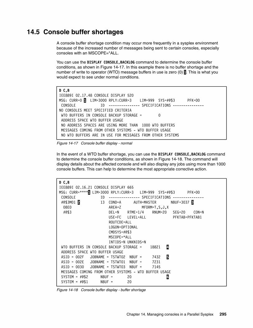
14.5 Console buffer shortages
A console buffer shortage condition may occur more frequently in a sysplex environment because of the increased number of messages being sent to certain consoles, especially consoles with an MSCOPE=*ALL.
You can use the DISPLAY CONSOLE,BACKLOG command to determine the console buffer conditions, as shown in Figure 14-17. In this example there is no buffer shortage and the number of write to operator (WTO) message buffers in use is zero (0) 1. This is what you would expect to see under normal conditions.
Figure 14-17 Console buffer display - normal
In the event of a WTO buffer shortage, you can use the DISPLAY CONSOLE,BACKLOG command to determine the console buffer conditions, as shown in Figure 14-18. The command will display details about the affected console and will also display any jobs using more than 1000 console buffers. This can help to determine the most appropriate corrective action.
Figure 14-18 Console buffer display - buffer shortage
D C,B IEE889I 02.17.48 CONSOLE DISPLAY 520 MSG: CURR=0 1 LIM=3000 RPLY:CURR=3 LIM=999 SYS=#@$3 PFK=00 CONSOLE ID --------------- SPECIFICATIONS ---------------NO CONSOLES MEET SPECIFIED CRITERIA WTO BUFFERS IN CONSOLE BACKUP STORAGE = 0 ADDRESS SPACE WTO BUFFER USAGE NO ADDRESS SPACES ARE USING MORE THAN 1000 WTO BUFFERS MESSAGES COMING FROM OTHER SYSTEMS - WTO BUFFER USAGE NO WTO BUFFERS ARE IN USE FOR MESSAGES FROM OTHER SYSTEMS
D C,B IEE889I 02.16.21 CONSOLE DISPLAY 665 MSG: CURR=****1 LIM=3000 RPLY:CURR=3 LIM=999 SYS=#@$3 PFK=00 CONSOLE ID --------------- SPECIFICATIONS --------------- #@$3M01 2 13 COND=A AUTH=MASTER NBUF=3037 3 08E0 AREA=Z MFORM=T,S,J,X #@$3 DEL=N RTME=1/4 RNUM=20 SEG=20 CON=N USE=FC LEVEL=ALL PFKTAB=PFKTAB1 ROUTCDE=ALL LOGON=OPTIONAL CMDSYS=#@$3 MSCOPE=*ALL INTIDS=N UNKNIDS=N WTO BUFFERS IN CONSOLE BACKUP STORAGE = 18821 4 ADDRESS SPACE WTO BUFFER USAGE ASID = 002F JOBNAME = TSTWTO2 NBUF = 7432 5 ASID = 002E JOBNAME = TSTWTO1 NBUF = 7231 ASID = 0030 JOBNAME = TSTWTO3 NBUF = 7145 MESSAGES COMING FROM OTHER SYSTEMS - WTO BUFFER USAGE SYSTEM = #@$2 NBUF = 20 6 SYSTEM = #@$1 NBUF = 20
Chapter 14. Managing consoles in a Parallel Sysplex 295
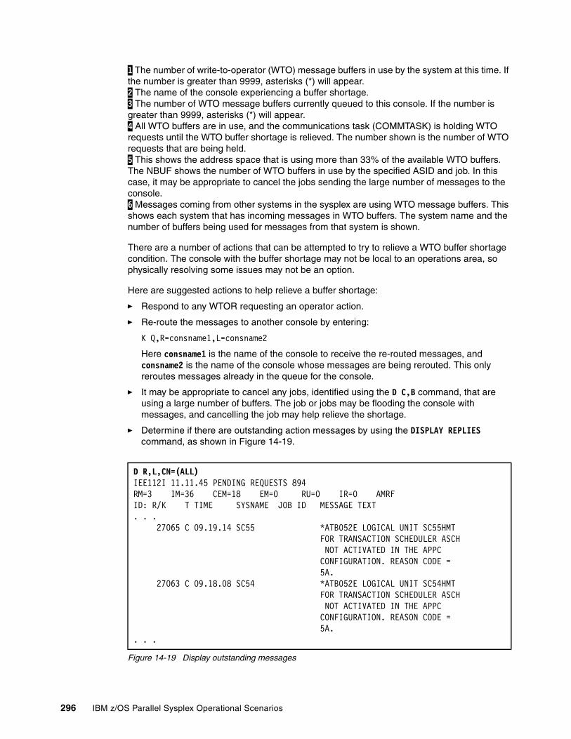
1 The number of write-to-operator (WTO) message buffers in use by the system at this time. If the number is greater than 9999, asterisks (*) will appear. 2 The name of the console experiencing a buffer shortage. 3 The number of WTO message buffers currently queued to this console. If the number is greater than 9999, asterisks (*) will appear. 4 All WTO buffers are in use, and the communications task (COMMTASK) is holding WTO requests until the WTO buffer shortage is relieved. The number shown is the number of WTO requests that are being held. 5 This shows the address space that is using more than 33% of the available WTO buffers. The NBUF shows the number of WTO buffers in use by the specified ASID and job. In this case, it may be appropriate to cancel the jobs sending the large number of messages to the console. 6 Messages coming from other systems in the sysplex are using WTO message buffers. This shows each system that has incoming messages in WTO buffers. The system name and the number of buffers being used for messages from that system is shown.
There are a number of actions that can be attempted to try to relieve a WTO buffer shortage condition. The console with the buffer shortage may not be local to an operations area, so physically resolving some issues may not be an option.
Here are suggested actions to help relieve a buffer shortage:
� Respond to any WTOR requesting an operator action.
� Re-route the messages to another console by entering:
K Q,R=consname1,L=consname2
Here consname1 is the name of the console to receive the re-routed messages, and consname2 is the name of the console whose messages are being rerouted. This only reroutes messages already in the queue for the console.
� It may be appropriate to cancel any jobs, identified using the D C,B command, that are using a large number of buffers. The job or jobs may be flooding the console with messages, and cancelling the job may help relieve the shortage.
� Determine if there are outstanding action messages by using the DISPLAY REPLIES command, as shown in Figure 14-19.
Figure 14-19 Display outstanding messages
D R,L,CN=(ALL)IEE112I 11.11.45 PENDING REQUESTS 894RM=3 IM=36 CEM=18 EM=0 RU=0 IR=0 AMRFID: R/K T TIME SYSNAME JOB ID MESSAGE TEXT. . .
27065 C 09.19.14 SC55 *ATB052E LOGICAL UNIT SC55HMT FOR TRANSACTION SCHEDULER ASCH NOT ACTIVATED IN THE APPC CONFIGURATION. REASON CODE = 5A.
27063 C 09.18.08 SC54 *ATB052E LOGICAL UNIT SC54HMT FOR TRANSACTION SCHEDULER ASCH NOT ACTIVATED IN THE APPC CONFIGURATION. REASON CODE = 5A.. . .
296 IBM z/OS Parallel Sysplex Operational Scenarios
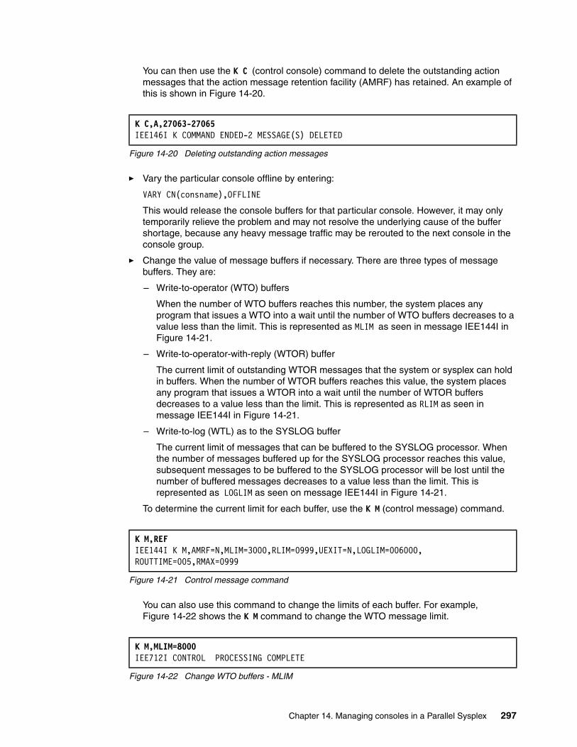
You can then use the K C (control console) command to delete the outstanding action messages that the action message retention facility (AMRF) has retained. An example of this is shown in Figure 14-20.
Figure 14-20 Deleting outstanding action messages
� Vary the particular console offline by entering:
VARY CN(consname),OFFLINE
This would release the console buffers for that particular console. However, it may only temporarily relieve the problem and may not resolve the underlying cause of the buffer shortage, because any heavy message traffic may be rerouted to the next console in the console group.
� Change the value of message buffers if necessary. There are three types of message buffers. They are:
– Write-to-operator (WTO) buffers
When the number of WTO buffers reaches this number, the system places any program that issues a WTO into a wait until the number of WTO buffers decreases to a value less than the limit. This is represented as MLIM as seen in message IEE144I in Figure 14-21.
– Write-to-operator-with-reply (WTOR) buffer
The current limit of outstanding WTOR messages that the system or sysplex can hold in buffers. When the number of WTOR buffers reaches this value, the system places any program that issues a WTOR into a wait until the number of WTOR buffers decreases to a value less than the limit. This is represented as RLIM as seen in message IEE144I in Figure 14-21.
– Write-to-log (WTL) as to the SYSLOG buffer
The current limit of messages that can be buffered to the SYSLOG processor. When the number of messages buffered up for the SYSLOG processor reaches this value, subsequent messages to be buffered to the SYSLOG processor will be lost until the number of buffered messages decreases to a value less than the limit. This is represented as LOGLIM as seen on message IEE144I in Figure 14-21.
To determine the current limit for each buffer, use the K M (control message) command.
Figure 14-21 Control message command
You can also use this command to change the limits of each buffer. For example, Figure 14-22 shows the K M command to change the WTO message limit.
Figure 14-22 Change WTO buffers - MLIM
K C,A,27063-27065IEE146I K COMMAND ENDED-2 MESSAGE(S) DELETED
K M,REF IEE144I K M,AMRF=N,MLIM=3000,RLIM=0999,UEXIT=N,LOGLIM=006000,ROUTTIME=005,RMAX=0999
K M,MLIM=8000IEE712I CONTROL PROCESSING COMPLETE
Chapter 14. Managing consoles in a Parallel Sysplex 297

Increasing the limits specified may require the use of more private storage in the console address space (for MLIM) and ECSA for RLIM and LOGLIM, which may create other system performance concerns. The maximum values of each type of buffer are listed in Table 14-1.
Table 14-1 Maximum console buffer values
� Deleting the message queue by using a K Q command is also an option. Use this command to delete messages that are queued to an MCS or SMCS console (not EMCS). This action affects only messages currently on the console's queue. Subsequent messages are queued as usual, so the command may need to be issued a number of times. Remember that the messages deleted from the queue will be lost. Use the following command:
K Q[,L=consname]
Here L=consname is the name of the console whose message queue is to be deleted, or blank defaults to the console where the command is issued.
14.6 Entering z/OS commands
When operating in a sysplex environment, it is possible to enter commands for execution on any system or systems in the sysplex. This section examines the various methods that you can use to accomplish this.
14.6.1 CMDSYS parameter
Each console has a CMDSYS parameter specified when it is connected to a system in a sysplex. Although this parameter is usually pointing to the system where the console is assigned, or logged on to, it can point to any system in the sysplex. The CMDSYS parameter specifies the name of the system for which this console has command association, which means any command issued from the console will be issued to the system assigned on the CMDSYS parameter. This system might be different from the system where this console is physically attached.
Some systems do not have a console physically connected to them. In this case, it may make sense to set up a console on another system with a CMDSYS parameter associated to the system with no consoles attached. All commands entered on a console will be executed on the system specified in the CMDSYS parameter, as long as no other routing options are used.
To determine the CMDSYS parameter of an MCS console, view the IEE612I message line on the bottom of the console display (MCS and SMCS consoles); see Figure 14-23.
Figure 14-23 CMDSYS parameter on the console
Type Parameter Maximum
WTO MLIM 9999
WTOR RLIM 9999
WTL LOGLIM 999999
IEE612I CN=#@$3M01 DEVNUM=08E0 SYS=#@$3 CMDSYS=#@$3
298 IBM z/OS Parallel Sysplex Operational Scenarios
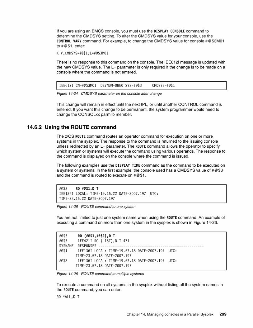
If you are using an EMCS console, you must use the DISPLAY CONSOLE command to determine the CMDSYS setting. To alter the CMDSYS value for your console, use the CONTROL VARY command. For example, to change the CMDSYS value for console #@$3M01 to #@$1, enter:
K V,CMDSYS=#@$1,L=#@$3M01
There is no response to this command on the console. The IEE612I message is updated with the new CMDSYS value. The L= parameter is only required if the change is to be made on a console where the command is not entered.
Figure 14-24 CMDSYS parameter on the console after change
This change will remain in effect until the next IPL, or until another CONTROL command is entered. If you want this change to be permanent, the system programmer would need to change the CONSOLxx parmlib member.
14.6.2 Using the ROUTE command
The z/OS ROUTE command routes an operator command for execution on one or more systems in the sysplex. The response to the command is returned to the issuing console unless redirected by an L= parameter. The ROUTE command allows the operator to specify which system or systems will execute the command using various operands. The response to the command is displayed on the console where the command is issued.
The following examples use the DISPLAY TIME command as the command to be executed on a system or systems. In the first example, the console used has a CMDSYS value of #@$3 and the command is routed to execute on #@$1.
Figure 14-25 ROUTE command to one system
You are not limited to just one system name when using the ROUTE command. An example of executing a command on more than one system in the sysplex is shown in Figure 14-26.
Figure 14-26 ROUTE command to multiple systems
To execute a command on all systems in the sysplex without listing all the system names in the ROUTE command, you can enter:
RO *ALL,D T
IEE612I CN=#@$3M01 DEVNUM=08E0 SYS=#@$3 CMDSYS=#@$1
#@$3 RO #@$1,D TIEE136I LOCAL: TIME=19.15.22 DATE=2007.197 UTC:TIME=23.15.22 DATE=2007.197
#@$3 RO (#@$1,#@$2),D T#@$3 IEE421I RO (LIST),D T 471 SYSNAME RESPONSES ---------------------------------------------------#@$1 IEE136I LOCAL: TIME=19.57.18 DATE=2007.197 UTC: TIME=23.57.18 DATE=2007.197 #@$2 IEE136I LOCAL: TIME=19.57.18 DATE=2007.197 UTC: TIME=23.57.18 DATE=2007.197
Chapter 14. Managing consoles in a Parallel Sysplex 299
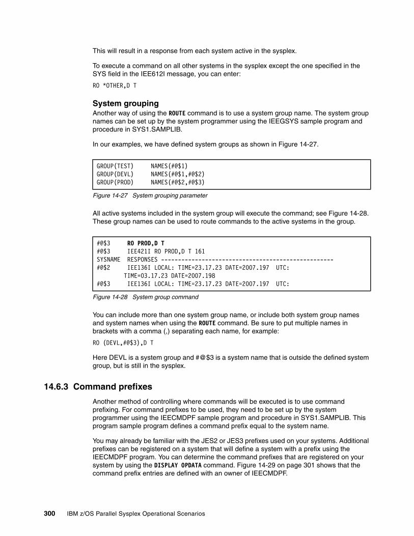
This will result in a response from each system active in the sysplex.
To execute a command on all other systems in the sysplex except the one specified in the SYS field in the IEE612I message, you can enter:
RO *OTHER,D T
System groupingAnother way of using the ROUTE command is to use a system group name. The system group names can be set up by the system programmer using the IEEGSYS sample program and procedure in SYS1.SAMPLIB.
In our examples, we have defined system groups as shown in Figure 14-27.
Figure 14-27 System grouping parameter
All active systems included in the system group will execute the command; see Figure 14-28. These group names can be used to route commands to the active systems in the group.
Figure 14-28 System group command
You can include more than one system group name, or include both system group names and system names when using the ROUTE command. Be sure to put multiple names in brackets with a comma (,) separating each name, for example:
RO (DEVL,#@$3),D T
Here DEVL is a system group and #@$3 is a system name that is outside the defined system group, but is still in the sysplex.
14.6.3 Command prefixes
Another method of controlling where commands will be executed is to use command prefixing. For command prefixes to be used, they need to be set up by the system programmer using the IEECMDPF sample program and procedure in SYS1.SAMPLIB. This program sample program defines a command prefix equal to the system name.
You may already be familiar with the JES2 or JES3 prefixes used on your systems. Additional prefixes can be registered on a system that will define a system with a prefix using the IEECMDPF program. You can determine the command prefixes that are registered on your system by using the DISPLAY OPDATA command. Figure 14-29 on page 301 shows that the command prefix entries are defined with an owner of IEECMDPF.
GROUP(TEST) NAMES(#@$1) GROUP(DEVL) NAMES(#@$1,#@$2) GROUP(PROD) NAMES(#@$2,#@$3)
#@$3 RO PROD,D T#@$3 IEE421I RO PROD,D T 161 SYSNAME RESPONSES ---------------------------------------------------#@$2 IEE136I LOCAL: TIME=23.17.23 DATE=2007.197 UTC: TIME=03.17.23 DATE=2007.198 #@$3 IEE136I LOCAL: TIME=23.17.23 DATE=2007.197 UTC:
300 IBM z/OS Parallel Sysplex Operational Scenarios
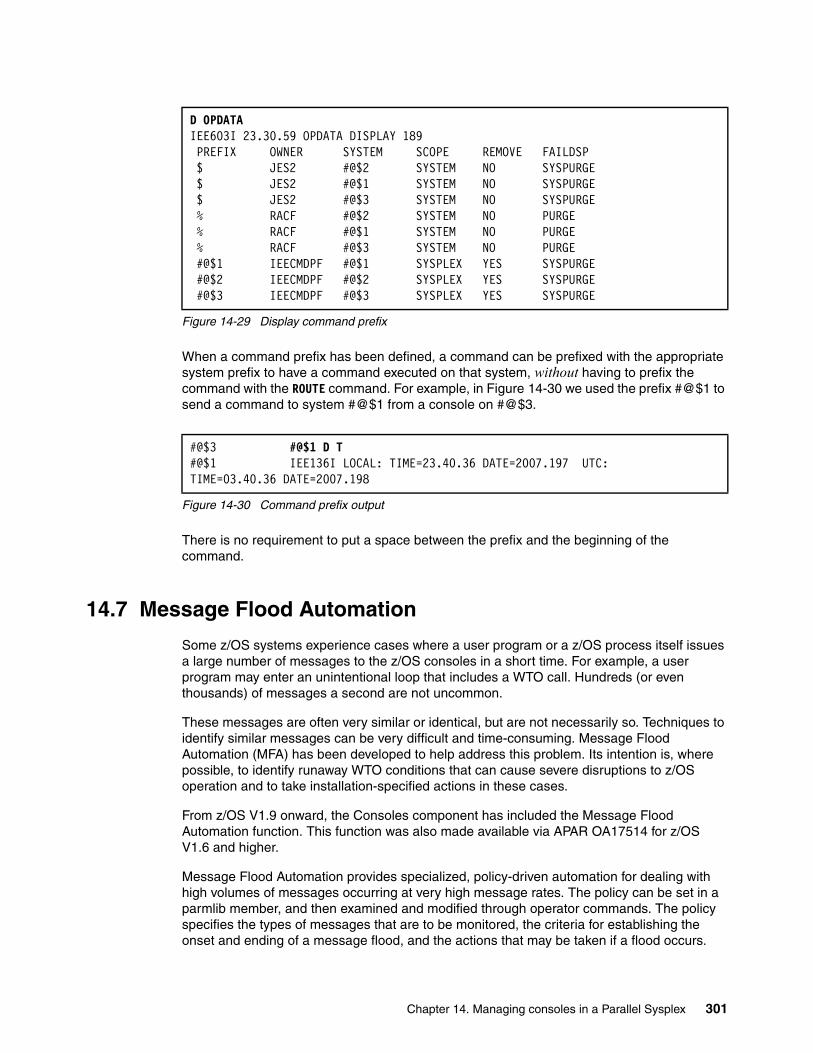
Figure 14-29 Display command prefix
When a command prefix has been defined, a command can be prefixed with the appropriate system prefix to have a command executed on that system, without having to prefix the command with the ROUTE command. For example, in Figure 14-30 we used the prefix #@$1 to send a command to system #@$1 from a console on #@$3.
Figure 14-30 Command prefix output
There is no requirement to put a space between the prefix and the beginning of the command.
14.7 Message Flood Automation
Some z/OS systems experience cases where a user program or a z/OS process itself issues a large number of messages to the z/OS consoles in a short time. For example, a user program may enter an unintentional loop that includes a WTO call. Hundreds (or even thousands) of messages a second are not uncommon.
These messages are often very similar or identical, but are not necessarily so. Techniques to identify similar messages can be very difficult and time-consuming. Message Flood Automation (MFA) has been developed to help address this problem. Its intention is, where possible, to identify runaway WTO conditions that can cause severe disruptions to z/OS operation and to take installation-specified actions in these cases.
From z/OS V1.9 onward, the Consoles component has included the Message Flood Automation function. This function was also made available via APAR OA17514 for z/OS V1.6 and higher.
Message Flood Automation provides specialized, policy-driven automation for dealing with high volumes of messages occurring at very high message rates. The policy can be set in a parmlib member, and then examined and modified through operator commands. The policy specifies the types of messages that are to be monitored, the criteria for establishing the onset and ending of a message flood, and the actions that may be taken if a flood occurs.
D OPDATA IEE603I 23.30.59 OPDATA DISPLAY 189 PREFIX OWNER SYSTEM SCOPE REMOVE FAILDSP $ JES2 #@$2 SYSTEM NO SYSPURGE $ JES2 #@$1 SYSTEM NO SYSPURGE $ JES2 #@$3 SYSTEM NO SYSPURGE % RACF #@$2 SYSTEM NO PURGE % RACF #@$1 SYSTEM NO PURGE % RACF #@$3 SYSTEM NO PURGE #@$1 IEECMDPF #@$1 SYSPLEX YES SYSPURGE #@$2 IEECMDPF #@$2 SYSPLEX YES SYSPURGE #@$3 IEECMDPF #@$3 SYSPLEX YES SYSPURGE
#@$3 #@$1 D T#@$1 IEE136I LOCAL: TIME=23.40.36 DATE=2007.197 UTC:TIME=03.40.36 DATE=2007.198
Chapter 14. Managing consoles in a Parallel Sysplex 301
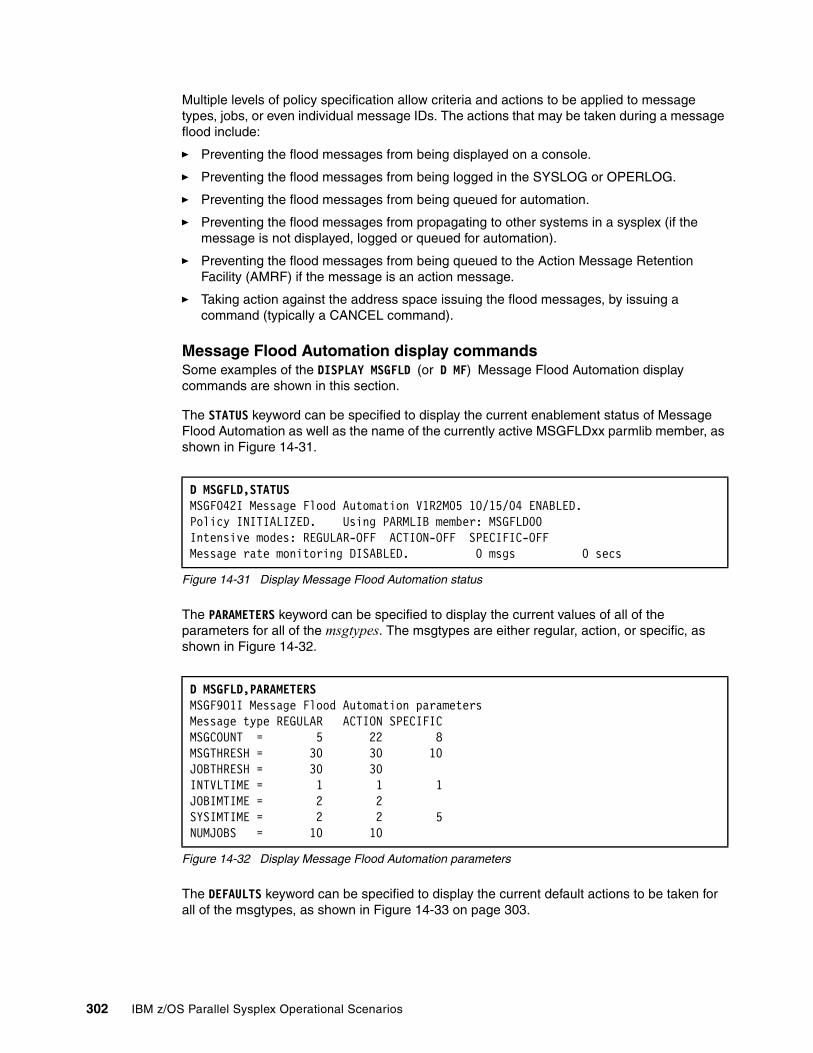
Multiple levels of policy specification allow criteria and actions to be applied to message types, jobs, or even individual message IDs. The actions that may be taken during a message flood include:
� Preventing the flood messages from being displayed on a console.
� Preventing the flood messages from being logged in the SYSLOG or OPERLOG.
� Preventing the flood messages from being queued for automation.
� Preventing the flood messages from propagating to other systems in a sysplex (if the message is not displayed, logged or queued for automation).
� Preventing the flood messages from being queued to the Action Message Retention Facility (AMRF) if the message is an action message.
� Taking action against the address space issuing the flood messages, by issuing a command (typically a CANCEL command).
Message Flood Automation display commandsSome examples of the DISPLAY MSGFLD (or D MF) Message Flood Automation display commands are shown in this section.
The STATUS keyword can be specified to display the current enablement status of Message Flood Automation as well as the name of the currently active MSGFLDxx parmlib member, as shown in Figure 14-31.
Figure 14-31 Display Message Flood Automation status
The PARAMETERS keyword can be specified to display the current values of all of the parameters for all of the msgtypes. The msgtypes are either regular, action, or specific, as shown in Figure 14-32.
Figure 14-32 Display Message Flood Automation parameters
The DEFAULTS keyword can be specified to display the current default actions to be taken for all of the msgtypes, as shown in Figure 14-33 on page 303.
D MSGFLD,STATUS MSGF042I Message Flood Automation V1R2M05 10/15/04 ENABLED. Policy INITIALIZED. Using PARMLIB member: MSGFLD00 Intensive modes: REGULAR-OFF ACTION-OFF SPECIFIC-OFF Message rate monitoring DISABLED. 0 msgs 0 secs
D MSGFLD,PARAMETERS MSGF901I Message Flood Automation parameters Message type REGULAR ACTION SPECIFIC MSGCOUNT = 5 22 8 MSGTHRESH = 30 30 10 JOBTHRESH = 30 30 INTVLTIME = 1 1 1 JOBIMTIME = 2 2 SYSIMTIME = 2 2 5 NUMJOBS = 10 10
302 IBM z/OS Parallel Sysplex Operational Scenarios

Figure 14-33 Display Message Flood Automation defaults
The JOBS keyword can be specified to display the current default actions to be taken for all of the jobs that have been defined in the active MSGFLDxx parmlib member, as shown in Figure 14-34.
Figure 14-34 Display Message Flood Automation jobs
The MSGS keyword can be specified to display the current default actions to be taken for all of the messages that have been defined in the active MSGFLDxx parmlib member, as shown in Figure 14-35.
Figure 14-35 Display Message Flood Automation messages
The MODE keyword can be specified to display the current intensive mode states for the three message types, as shown in Figure 14-36.
Figure 14-36 Display Message Flood Automation mode
D MSGFLD,DEFAULTS MSGF904I Message Flood Automation DEFAULTS Message type REGULAR ACTION SPECIFIC LOG = Y Y N AUTO = Y Y N DISPLAY = N N N CMD = N N RETAIN = N N
D MSGFLD,JOBS MSGF905I Message Flood Automation JOB actions REGULAR messages LOG AUTO DISPLAY CMD RETAIN JOB D1%%MSTR Y N N N ACTION messages LOG AUTO DISPLAY CMD RETAIN JOB D2%%MSTR Y N N N N
D MSGFLD,MSGS MSGF906I Message Flood Automation MSG actions SPECIFIC messages LOG AUTO DISPLAY CMD RETAIN MSG IOS000I N N N N MSG IOS002A N N N N
MSG IOS291I N N N N MSG IEA476E N N N N MSG IEA491E N N N N MSG IEA494I N N N N MSG IEA497I N N N N MSG IOS251I N N N N MSG IOS444I N N N N MSG IOS450E N N N N
. . .
D MSGFLD,MODE MSGF040I Intensive modes: REGULAR-OFF ACTION-OFF SPECIFIC-OFF
Chapter 14. Managing consoles in a Parallel Sysplex 303
14.8 Removing consoles using IEARELCN or IEARELEC
The current limit is 99 consoles in a sysplex, so it is possible to eventually run out of consoles. Some customers have performed an unwanted IPL to recapture orphan consoles.
To remove a console definition for MCS and SMCS consoles, you can use the sample JCL for program IEARELCN in SYS1.SAMPLIB. The use of the IEARELCN program is described in MVS Planning: Operations, SA22-7601. Similarly, to remove a console definition for EMCS consoles, you can use the sample JCL for program IEARELEC in SYS1.SAMPLIB.
In a sysplex, deleting a console definition releases the console ID associated with the console and makes it available for other console definitions. Thus, you have flexibility controlling the number of console IDs you need in an active console configuration. For example, if you define 10 consoles in CONSOLxx and you have used the VARY CONSOLE OFFLINE command for one of the consoles (so it is inactive), the system still associates the console ID with the inactive console. Using the console service, you can delete the console definition, thereby making the console ID available for reuse. When you add a new console, the system reassigns the console ID. This action would need to be done by a system programmer.
14.9 z/OS Management Console
There is also a graphical user interface (GUI) for monitoring your systems, and it is known as the IBM Tivoli OMEGAMON® z/OS Management Console. It displays and collects health check and availability information about z/OS systems and sysplex resources, and reports the information in the Tivoli Enterprise Portal GUI. The product workspaces provide health check information for z/OS systems, and configuration status information for z/OS systems and sysplex resources. The user interface contains expert advice on alerts.
The OMEGAMON z/OS Management Console contains a subset of the availability and sysplex monitoring functions of the IBM Tivoli OMEGAMON XE on z/OS product. In addition, it uses IBM Health Checker for z/OS (this must also be active on your systems) to monitor systems for potential problems, and it monitors Health Checker for z/OS for problems.
The OMEGAMON z/OS Management Console displays the following types of z/OS data:
� Availability
– Operations status, including outstanding WTOR and WTO buffers remaining – Address space data – Coupling facility policy information – Coupling facility systems data – Coupling facility structures data – Coupling facility structure connections data – Coupling facility paths data – LPAR clusters data – UNIX System Services address spaces and processes data – Paging data set data – Cross-system coupling facility (XCF) systems data – XCF paths data
304 IBM z/OS Parallel Sysplex Operational Scenarios

� IBM Health Checker for z/OS data
– Including status of the product and checks. The checks performed by the IBM Health Checker for z/OS identify potential problems before they affect your availability or, in worst cases, cause outages. IBM Health Checker for z/OS periodically runs the element, product, vendor, or installation checks to look at the current active z/OS and sysplex settings and definitions for a system, and compares the values to those suggested by IBM or defined by you. See Chapter 12, “IBM z/OS Health Checker” on page 257 for more detailed information about this topic.
The Tivoli OMEGAMON z/OS Management Console has a Java™-based interface known as the Tivoli Enterprise Portal, which you can access via a Web browser. You can set threshold levels and flags as desired to alert you when the systems reach critical points. Refer to IBM OMEGAMON z/OS Management Console User’s Guide, GC32-1955, for more details.
WorkspaceA workspace is the work area of the Tivoli Enterprise Portal application window. It is comprised of one or more views. A view is a pane in the workspace (typically a chart, graph, or table) showing data collected by a monitoring agent. As you select items in the Navigator, each workspace presents views relevant to your selection. Every workspace has at least one view, and every view has a set of properties associated with it. You can customize the workspace by working in the Properties Editor to change the style and content of each view. You can also change, add, and delete views on a workspace.
An example of the sysplex information available from the z/OS Management Console is the Coupling Facility Systems Data for Sysplex workspace report shown in Figure 14-37. This report displays status and storage information about the Coupling Facilities defined to the sysplex. This workspace contains views such as;
� The Dump Table Storage bar chart, which shows each Coupling Facility; the number of 4 K pages of storage reserved for dump tables; the number of pages currently holding dumps; and the percentage of allocated storage currently being used.
� The Coupling Facility Systems Information table displays basic status and storage statistics for each Coupling Facility. From this table, you can link to the other workspaces for the selected Coupling Facility
Figure 14-37 z/OS Management Console - CF view
Chapter 14. Managing consoles in a Parallel Sysplex 305
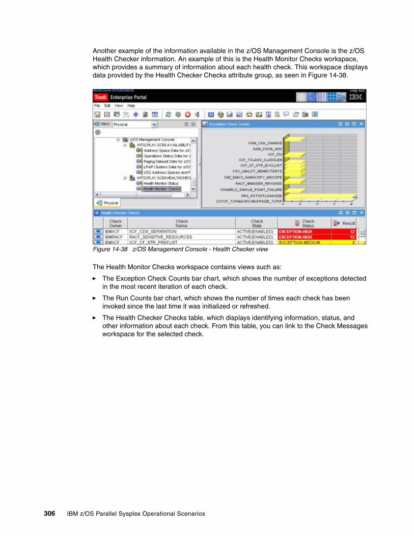
Another example of the information available in the z/OS Management Console is the z/OS Health Checker information. An example of this is the Health Monitor Checks workspace, which provides a summary of information about each health check. This workspace displays data provided by the Health Checker Checks attribute group, as seen in Figure 14-38.
Figure 14-38 z/OS Management Console - Health Checker view
The Health Monitor Checks workspace contains views such as:
� The Exception Check Counts bar chart, which shows the number of exceptions detected in the most recent iteration of each check.
� The Run Counts bar chart, which shows the number of times each check has been invoked since the last time it was initialized or refreshed.
� The Health Checker Checks table, which displays identifying information, status, and other information about each check. From this table, you can link to the Check Messages workspace for the selected check.
306 IBM z/OS Parallel Sysplex Operational Scenarios

Chapter 15. z/OS system logger considerations
This chapter describes the operational aspects of the system logger, including:
� Starting and stopping the system logger address space
� Displaying system logger information; structures and log streams
� System logger offload monitoring
� Handling a shortage of system logger directory extents
� System logger structure rebuilds
� Logrec use of log streams as an exploiter of system logger
For more detailed information about the z/OS system logger, see Systems Programmer’s Guide to: z/OS System Logger, SG24-6898, and MVS Setting Up a Sysplex, SA22-7625.
15
© Copyright IBM Corp. 2009. All rights reserved. 307

15.1 Introduction to z/OS system logger
The z/OS system logger is a z/OS component designed to support system and subsystem components in a Parallel Sysplex. It implements a set of services that enables applications to write, read, and delete log data into what is known as a log stream. A log stream is a sequential series of log records written by the system logger at the request of a log writer (an exploiter like CICS). The records are written in the order of their arrival and may be retrieved sequentially, forward or backward, or uniquely, by a log token (key).
System, subsystem, or application components can exploit the system logger functions. The system logger takes the responsibility for tasks such as saving log data, retrieving the data (potentially from any system in the sysplex), archiving the data, and expiring the data. In addition, system logger provides the ability to have a single, merged log, containing log data from multiple instances of an application within the sysplex.
Log data managed by the system logger may reside in processor storage, in a Coupling Facility structure, on DASD, or potentially, on tape. However, regardless of where system logger is currently storing a given log record, from the point of view of the exploiter, all the log records are kept in a single file that is a limited size.
The task of tracking where a specific piece of log data is at any given time is handled by system logger. Additionally, system logger will manage the utilization of its storage; as the space in one medium starts filling up (a Coupling Facility structure, for example), logger will move old data to the next level in the hierarchy (an offload dataset on DASD, for example). The location of the data, and the migration of that data from one level to another, is transparent to the application and is managed completely by system logger, as illustrated in Figure 15-1.
Figure 15-1 Logical and physical views of system logger-maintained log data
308 IBM z/OS Parallel Sysplex Operational Scenarios

There are basically two types of users of system logger. One type of exploiter uses the system logger as an archival facility for log data; for example, OPERLOG or LOGREC. The second type of exploiter typically uses the data more actively, and explicitly deletes it when it is no longer required; for example, the CICS DFHLOG. CICS stores information in DFHLOG about running transactions, and deletes the records as the transactions complete. These are called active exploiters.
15.1.1 Where system logger stores its data
When an application passes log data to system logger, the data can initially be stored on DASD, in what is known as a DASD-only log stream, or it can be stored in a Coupling Facility (CF) in what is known as a CF-Structure log stream. The major differences between these two types of log stream configurations are the storage medium system logger uses to hold interim log data. Interim storage is the primary storage used to hold log data that has not yet been offloaded. Another major difference is how many systems can use the log stream concurrently;
� In a CF log stream, interim storage for log data is in CF list structures. This type of log stream supports the ability for exploiters on more than one system to write log data to the same log stream concurrently. Log data that is in interim storage is duplexed to protect against data loss conditions. This data is usually duplexed to a data space, although log streams residing in a CF structure may optionally be duplexed to a staging data set, or utilize system managed duplexing.
� In a DASD-only log stream, interim storage for log data is contained in a data space in the z/OS system. The dataspaces are associated with the system logger address space, IXGLOGR. DASD-only log streams can only be used by exploiters on one system at a time. Log data that is in interim storage is duplexed to protect against data loss conditions, which for DASD-only log streams is usually to a staging data set.
15.2 Starting and stopping the system logger address space
The system logger address space (IXGLOGR) starts automatically, as an MVS system component address space, during an IPL on each system image.
If the IXGLOGR address space fails for some reason the system will automatically restart the address space, unless it is terminated using the FORCE IXGLOGR,ARM command.
If for any reason, you need to terminate the system logger address space, you will need to issue the FORCE IXGLOGR,ARM command. The only way to restart the system logger address space is through the S IXGLOGRS procedure. After a FORCE command has been issued against the system logger address space, the system issues IXG056I and IXG067E messages to prompt the operator to manually restart the system logger address space, as shown in Figure 15-2.
Figure 15-2 System logger address space restart
IXGLOGRS is the command processor to start the system logger address space. IXGLOGRS only starts the system logger address space (IXGLOGR) and then it immediately ends.
IXG056I SYSTEM LOGGER ADDRESS SPACE HAS ENDED. 171 OPERATOR ISSUED FORCE COMMAND. MANUAL RESTART REQUIRED.IXG067E ISSUE S IXGLOGRS TO RESTART SYSTEM LOGGER.
Chapter 15. z/OS system logger considerations 309
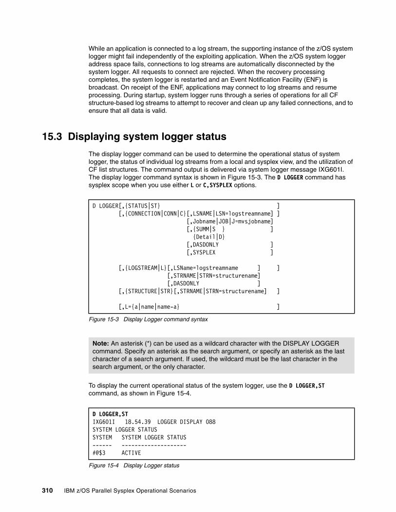
While an application is connected to a log stream, the supporting instance of the z/OS system logger might fail independently of the exploiting application. When the z/OS system logger address space fails, connections to log streams are automatically disconnected by the system logger. All requests to connect are rejected. When the recovery processing completes, the system logger is restarted and an Event Notification Facility (ENF) is broadcast. On receipt of the ENF, applications may connect to log streams and resume processing. During startup, system logger runs through a series of operations for all CF structure-based log streams to attempt to recover and clean up any failed connections, and to ensure that all data is valid.
15.3 Displaying system logger status
The display logger command can be used to determine the operational status of system logger, the status of individual log streams from a local and sysplex view, and the utilization of CF list structures. The command output is delivered via system logger message IXG601I. The display logger command syntax is shown in Figure 15-3. The D LOGGER command has sysplex scope when you use either L or C,SYSPLEX options.
Figure 15-3 Display Logger command syntax
To display the current operational status of the system logger, use the D LOGGER,ST command, as shown in Figure 15-4.
Figure 15-4 Display Logger status
D LOGGER[,{STATUS|ST} ] [,{CONNECTION|CONN|C}[,LSNAME|LSN=logstreamname] ] [,Jobname|JOB|J=mvsjobname] [,{SUMM|S } ] {Detail|D} [,DASDONLY ]
[,SYSPLEX ] [,{LOGSTREAM|L}[,LSName=logstreamname ] ] [,STRNAME|STRN=structurename] [,DASDONLY ] [,{STRUCTURE|STR}[,STRNAME|STRN=structurename] ] [,L={a|name|name-a} ]
Note: An asterisk (*) can be used as a wildcard character with the DISPLAY LOGGER command. Specify an asterisk as the search argument, or specify an asterisk as the last character of a search argument. If used, the wildcard must be the last character in the search argument, or the only character.
D LOGGER,ST IXG601I 18.54.39 LOGGER DISPLAY 088SYSTEM LOGGER STATUS SYSTEM SYSTEM LOGGER STATUS ------ -------------------- #@$3 ACTIVE
310 IBM z/OS Parallel Sysplex Operational Scenarios
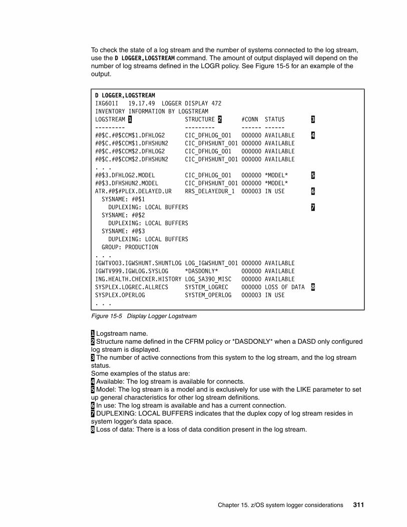
To check the state of a log stream and the number of systems connected to the log stream, use the D LOGGER,LOGSTREAM command. The amount of output displayed will depend on the number of log streams defined in the LOGR policy. See Figure 15-5 for an example of the output.
Figure 15-5 Display Logger Logstream
1 Logstream name. 2 Structure name defined in the CFRM policy or *DASDONLY* when a DASD only configured log stream is displayed. 3 The number of active connections from this system to the log stream, and the log stream status. Some examples of the status are: 4 Available: The log stream is available for connects. 5 Model: The log stream is a model and is exclusively for use with the LIKE parameter to set up general characteristics for other log stream definitions. 6 In use: The log stream is available and has a current connection. 7 DUPLEXING: LOCAL BUFFERS indicates that the duplex copy of log stream resides in system logger’s data space. 8 Loss of data: There is a loss of data condition present in the log stream.
D LOGGER,LOGSTREAM IXG601I 19.17.49 LOGGER DISPLAY 472 INVENTORY INFORMATION BY LOGSTREAM LOGSTREAM 1 STRUCTURE 2 #CONN STATUS 3 --------- --------- ------ ------ #@$C.#@$CCM$1.DFHLOG2 CIC_DFHLOG_001 000000 AVAILABLE 4 #@$C.#@$CCM$1.DFHSHUN2 CIC_DFHSHUNT_001 000000 AVAILABLE#@$C.#@$CCM$2.DFHLOG2 CIC_DFHLOG_001 000000 AVAILABLE#@$C.#@$CCM$2.DFHSHUN2 CIC_DFHSHUNT_001 000000 AVAILABLE. . . #@$3.DFHLOG2.MODEL CIC_DFHLOG_001 000000 *MODEL* 5#@$3.DFHSHUN2.MODEL CIC_DFHSHUNT_001 000000 *MODEL* ATR.#@$#PLEX.DELAYED.UR RRS_DELAYEDUR_1 000003 IN USE 6 SYSNAME: #@$1 DUPLEXING: LOCAL BUFFERS 7 SYSNAME: #@$2 DUPLEXING: LOCAL BUFFERS SYSNAME: #@$3 DUPLEXING: LOCAL BUFFERS GROUP: PRODUCTION . . . IGWTV003.IGWSHUNT.SHUNTLOG LOG_IGWSHUNT_001 000000 AVAILABLE IGWTV999.IGWLOG.SYSLOG *DASDONLY* 000000 AVAILABLE ING.HEALTH.CHECKER.HISTORY LOG_SA390_MISC 000000 AVAILABLE SYSPLEX.LOGREC.ALLRECS SYSTEM_LOGREC 000000 LOSS OF DATA 8 SYSPLEX.OPERLOG SYSTEM_OPERLOG 000003 IN USE . . .
Chapter 15. z/OS system logger considerations 311

To display all defined log streams that have a DASD-only configuration, use the D LOGGER,L,DASDONLY command. See Figure 15-6 for an example of the output.
Figure 15-6 Display Logger DASD only log stream
To check the number of connections to the log streams, use the D LOGGER,CONN command. This command displays only log streams that have connectors on the system where the command has been issued. See Figure 15-7 for an example of the output.
Figure 15-7 Display Logger connections
To display which jobnames are connected to the log stream, you can use the D LOGGER,CONN,LSN=<logstream>,DETAIL command. This command displays only those log streams that have connectors on the system where the command has been issued. See Figure 15-8 for an example of the output using the sysplex OPERLOG as the log stream example.
Figure 15-8 Display Logger R/W connections
D LOGGER,L,DASDONLY IXG601I 20.26.46 LOGGER DISPLAY 840 INVENTORY INFORMATION BY LOGSTREAM LOGSTREAM STRUCTURE #CONN STATUS --------- --------- ------ ------ BDG.LOG.STREAM *DASDONLY* 000000 AVAILABLEIGWTV999.IGWLOG.SYSLOG *DASDONLY* 000000 AVAILABLE
D LOGGER,CONN IXG601I 19.50.58 LOGGER DISPLAY 695 CONNECTION INFORMATION BY LOGSTREAM FOR SYSTEM #@$3 LOGSTREAM STRUCTURE #CONN STATUS--------- --------- ------ ------ATR.#@$#PLEX.RM.DATA RRS_RMDATA_1 000001 IN USEATR.#@$#PLEX.MAIN.UR RRS_MAINUR_1 000001 IN USESYSPLEX.OPERLOG SYSTEM_OPERLOG 000002 IN USEATR.#@$#PLEX.DELAYED.UR RRS_DELAYEDUR_1 000001 IN USEATR.#@$#PLEX.RESTART RRS_RESTART_1 000001 IN USE#@$#.SQ.MSGQ.LOG I#$#LOGMSGQ 000001 IN USE#@$#.SQ.EMHQ.LOG I#$#LOGEMHQ 000001 IN USE
D LOGGER,C,LSN=SYSPLEX.OPERLOG,DETAIL IXG601I 20.12.45 LOGGER DISPLAY 800 CONNECTION INFORMATION BY LOGSTREAM FOR SYSTEM #@$3 LOGSTREAM STRUCTURE #CONN STATUS --------- --------- ------ ------ SYSPLEX.OPERLOG SYSTEM_OPERLOG 000002 IN USE DUPLEXING: STAGING DATA SET STGDSN: IXGLOGR.SYSPLEX.OPERLOG.#@$3 VOLUME=#@$#W1 SIZE=004140 (IN 4K) % IN-USE=001 GROUP: PRODUCTION
JOBNAME: CONSOLE ASID: 000B R/W CONN: 000000 / 000001 RES MGR./CONNECTED: *NONE* / NO IMPORT CONNECT: NO
312 IBM z/OS Parallel Sysplex Operational Scenarios

To display which log streams are allocated to a particular structure, use the D LOGGER,STR command. The display shows whether a log stream is defined to the structure and whether it is connected. See Figure 15-9 for an example of the output.
Figure 15-9 Display Logger structures
15.4 Listing logstream information using IXCMIAPU
You can use the IXCMIAPU program to list additional information when reviewing possible loss of data in a log stream, as reported in Figure 15-5 on page 311. Notify your system programmer if any loss of data is identified.
The IXCMIAPU program can be used to list additional information about log streams. One of the features of the IXCMIAPU program for system logger (DATA TYPE(LOGR)) is its reporting ability. You can specify either LIST LOGSTREAM(lsname) or LIST STRUCTURE(strname), depending on the type of specific results you are looking for.
Specifying LIST STRUCTURE(strname) DETAIL(YES), where strname is the CF list structure name (wildcards are supported), generates a report listing the structure definition values, the effective average buffer size, and the log streams defined to structures listed.
Specifying LIST LOGSTREAM(lsname) DETAIL(YES), where lsname is the log stream name (wildcards are supported), generates a report listing all of the log streams matching the portion of the name specified. The output includes the log stream definition, names of any associated or possible orphan data sets, connection information, and structure definitions for
D LOGGER,STR IXG601I 20.22.19 LOGGER DISPLAY 825 INVENTORY INFORMATION BY STRUCTURE STRUCTURE GROUP CONNECTED--------- ----- ---------CIC_DFHLOG_001 PRODUCTION #@$C.#@$CCM$1.DFHLOG2 YES #@$C.#@$CCM$2.DFHLOG2 NO #@$C.#@$CCM$3.DFHLOG2 NO #@$C.#@$CWC2A.DFHLOG2 NO . . .LOG_TEST_001 *NO LOGSTREAMS DEFINED* N/A RRS_ARCHIVE_2 *NO LOGSTREAMS DEFINED* N/A RRS_DELAYEDUR_1 PRODUCTION ATR.#@$#PLEX.DELAYED.UR YES RRS_MAINUR_1 PRODUCTION ATR.#@$#PLEX.MAIN.UR YES RRS_RESTART_1 PRODUCTION ATR.#@$#PLEX.RESTART YES RRS_RMDATA_1 PRODUCTION ATR.#@$#PLEX.RM.DATA YES SYSTEM_LOGREC PRODUCTION SYSPLEX.LOGREC.ALLRECS NO SYSTEM_OPERLOG PRODUCTION SYSPLEX.OPERLOG YES
Chapter 15. z/OS system logger considerations 313

the CF Structure-based log streams. Without the DETAIL(YES) keyword, only the log stream definition are reported in the sysout.
Figure 15-10 JCL to list log steam data using IXCMIAPU
The output of the LOGR list report is shown in Figure 15-11 on page 315. The report shown is of the LOGREC log stream which has possible loss of data.
The listing shows the following:
1 Log stream information about how the log stream was defined. 2 Timing of the possible loss of data. 3 Log stream connection information, which shows the systems connected to the log stream and their connection status. 4 Offload data set name prefix. The data set is a linear VSAM data set. 5 Information about the offload data sets in the log stream, the sequence numbers, and the date and time of the oldest record in the data set.
//LOGRLIST JOB (0,0),'LIST LOGR POL',CLASS=A,REGION=4M, // MSGCLASS=X,NOTIFY=&SYSUID //STEP1 EXEC PGM=IXCMIAPU //SYSPRINT DD SYSOUT=* //SYSABEND DD SYSOUT=* //SYSIN DD * DATA TYPE(LOGR) REPORT(NO) LIST LOGSTREAM NAME(SYSPLEX.LOGREC.ALLRECS) DETAIL(YES)/*
314 IBM z/OS Parallel Sysplex Operational Scenarios
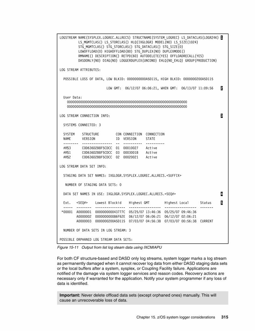
Figure 15-11 Output from list log steam data using IXCMIAPU
For both CF structure-based and DASD only log streams, system logger marks a log stream as permanently damaged when it cannot recover log data from either DASD staging data sets or the local buffers after a system, sysplex, or Coupling Facility failure. Applications are notified of the damage via system logger services and reason codes. Recovery actions are necessary only if warranted for the application. Notify your system programmer if any loss of data is identified.
LOGSTREAM NAME(SYSPLEX.LOGREC.ALLRECS) STRUCTNAME(SYSTEM_LOGREC) LS_DATACLAS(LOGR24K) 1 LS_MGMTCLAS() LS_STORCLAS() HLQ(IXGLOGR) MODEL(NO) LS_SIZE(1024) STG_MGMTCLAS() STG_STORCLAS() STG_DATACLAS() STG_SIZE(0) LOWOFFLOAD(0) HIGHOFFLOAD(80) STG_DUPLEX(NO) DUPLEXMODE() RMNAME() DESCRIPTION() RETPD(60) AUTODELETE(YES) OFFLOADRECALL(YES) DASDONLY(NO) DIAG(NO) LOGGERDUPLEX(UNCOND) EHLQ(NO_EHLQ) GROUP(PRODUCTION)
LOG STREAM ATTRIBUTES: POSSIBLE LOSS OF DATA, LOW BLKID: 0000000000A5D115, HIGH BLKID: 0000000200A5D115 LOW GMT: 06/12/07 06:06:21, WHEN GMT: 06/13/07 11:09:56 2 User Data: 0000000000000000000000000000000000000000000000000000000000000000 0000000000000000000000000000000000000000000000000000000000000000
LOG STREAM CONNECTION INFO: 3 SYSTEMS CONNECTED: 3 SYSTEM STRUCTURE CON CONNECTION CONNECTION NAME VERSION ID VERSION STATE -------- ---------------- -- ---------- ---------- #@$3 C0D636D2B8F5CDCC 01 00010027 Active #@$1 C0D636D2B8F5CDCC 03 0003001B Active #@$2 C0D636D2B8F5CDCC 02 00020021 Active
LOG STREAM DATA SET INFO: STAGING DATA SET NAMES: IXGLOGR.SYSPLEX.LOGREC.ALLRECS.<SUFFIX> NUMBER OF STAGING DATA SETS: 0 DATA SET NAMES IN USE: IXGLOGR.SYSPLEX.LOGREC.ALLRECS.<SEQ#> 4
Ext. <SEQ#> Lowest Blockid Highest GMT Highest Local Status 5 ----- -------- ---------------- ----------------- ----------------- ------- *00001 A0000001 000000000043777C 05/25/07 13:46:36 05/25/07 09:46:36 A0000002 000000000086F62E 06/12/07 06:06:21 06/12/07 02:06:21
A0000003 0000000200A5D115 07/03/07 04:56:38 07/03/07 00:56:38 CURRENT NUMBER OF DATA SETS IN LOG STREAM: 3
POSSIBLE ORPHANED LOG STREAM DATA SETS:
Important: Never delete offload data sets (except orphaned ones) manually. This will cause an unrecoverable loss of data.
Chapter 15. z/OS system logger considerations 315
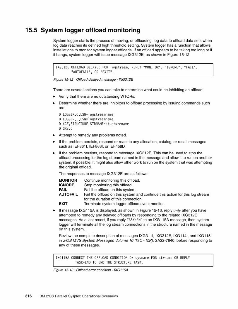
15.5 System logger offload monitoring
System logger starts the process of moving, or offloading, log data to offload data sets when log data reaches its defined high threshold setting. System logger has a function that allows installations to monitor system logger offloads. If an offload appears to be taking too long or if it hangs, system logger will issue message IXG312E, as shown in Figure 15-12.
Figure 15-12 Offload delayed message - IXG312E
There are several actions you can take to determine what could be inhibiting an offload:
� Verify that there are no outstanding WTORs.
� Determine whether there are inhibitors to offload processing by issuing commands such as:
D LOGGER,C,LSN=logstreamnameD LOGGER,L,LSN=logstreamnameD XCF,STRUCTURE,STRNAME=stucturenameD GRS,C
� Attempt to remedy any problems noted.
� If the problem persists, respond or react to any allocation, catalog, or recall messages such as IEF861I, IEF863I, or IEF458D.
� If the problem persists, respond to message IXG312E. This can be used to stop the offload processing for the log stream named in the message and allow it to run on another system, if possible. It might also allow other work to run on the system that was attempting the original offload.
The responses to message IXG312E are as follows:
MONITOR Continue monitoring this offload.IGNORE Stop monitoring this offload.FAIL Fail the offload on this system.AUTOFAIL Fail the offload on this system and continue this action for this log stream
for the duration of this connection.EXIT Terminate system logger offload event monitor.
� If message IXG115A is displayed, as shown in Figure 15-13, reply only after you have attempted to remedy any delayed offloads by responding to the related IXG312E messages. As a last resort, if you reply TASK=END to an IXG115A message, then system logger will terminate all the log stream connections in the structure named in the message on this system.
Review the complete description of messages IXG311I, IXG312E, IXG114I, and IXG115I in z/OS MVS System Messages Volume 10 (IXC - IZP), SA22-7640, before responding to any of these messages.
Figure 15-13 Offload error condition - IXG115A
IXG312E OFFLOAD DELAYED FOR logstream, REPLY "MONITOR", "IGNORE", "FAIL","AUTOFAIL", OR "EXIT".
IXG115A CORRECT THE OFFLOAD CONDITION ON sysname FOR strname OR REPLY TASK=END TO END THE STRUCTURE TASK.
316 IBM z/OS Parallel Sysplex Operational Scenarios
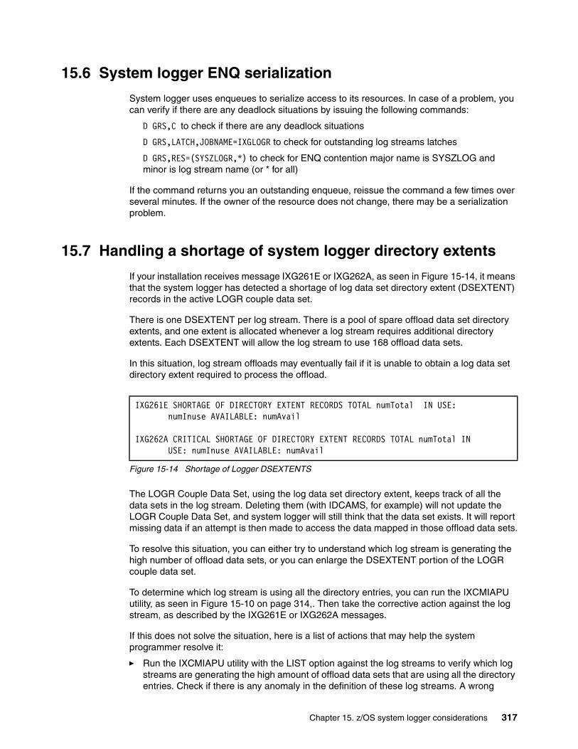
15.6 System logger ENQ serialization
System logger uses enqueues to serialize access to its resources. In case of a problem, you can verify if there are any deadlock situations by issuing the following commands:
D GRS,C to check if there are any deadlock situations
D GRS,LATCH,JOBNAME=IXGLOGR to check for outstanding log streams latches
D GRS,RES=(SYSZLOGR,*) to check for ENQ contention major name is SYSZLOG and minor is log stream name (or * for all)
If the command returns you an outstanding enqueue, reissue the command a few times over several minutes. If the owner of the resource does not change, there may be a serialization problem.
15.7 Handling a shortage of system logger directory extents
If your installation receives message IXG261E or IXG262A, as seen in Figure 15-14, it means that the system logger has detected a shortage of log data set directory extent (DSEXTENT) records in the active LOGR couple data set.
There is one DSEXTENT per log stream. There is a pool of spare offload data set directory extents, and one extent is allocated whenever a log stream requires additional directory extents. Each DSEXTENT will allow the log stream to use 168 offload data sets.
In this situation, log stream offloads may eventually fail if it is unable to obtain a log data set directory extent required to process the offload.
Figure 15-14 Shortage of Logger DSEXTENTS
The LOGR Couple Data Set, using the log data set directory extent, keeps track of all the data sets in the log stream. Deleting them (with IDCAMS, for example) will not update the LOGR Couple Data Set, and system logger will still think that the data set exists. It will report missing data if an attempt is then made to access the data mapped in those offload data sets.
To resolve this situation, you can either try to understand which log stream is generating the high number of offload data sets, or you can enlarge the DSEXTENT portion of the LOGR couple data set.
To determine which log stream is using all the directory entries, you can run the IXCMIAPU utility, as seen in Figure 15-10 on page 314,. Then take the corrective action against the log stream, as described by the IXG261E or IXG262A messages.
If this does not solve the situation, here is a list of actions that may help the system programmer resolve it:
� Run the IXCMIAPU utility with the LIST option against the log streams to verify which log streams are generating the high amount of offload data sets that are using all the directory entries. Check if there is any anomaly in the definition of these log streams. A wrong
IXG261E SHORTAGE OF DIRECTORY EXTENT RECORDS TOTAL numTotal IN USE: numInuse AVAILABLE: numAvail
IXG262A CRITICAL SHORTAGE OF DIRECTORY EXTENT RECORDS TOTAL numTotal IN USE: numInuse AVAILABLE: numAvail
Chapter 15. z/OS system logger considerations 317
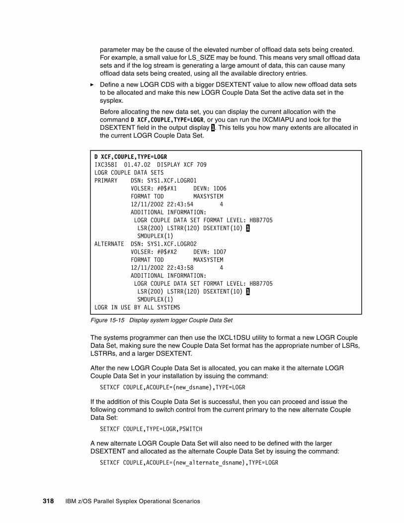
parameter may be the cause of the elevated number of offload data sets being created. For example, a small value for LS_SIZE may be found. This means very small offload data sets and if the log stream is generating a large amount of data, this can cause many offload data sets being created, using all the available directory entries.
� Define a new LOGR CDS with a bigger DSEXTENT value to allow new offload data sets to be allocated and make this new LOGR Couple Data Set the active data set in the sysplex.
Before allocating the new data set, you can display the current allocation with the command D XCF,COUPLE,TYPE=LOGR, or you can run the IXCMIAPU and look for the DSEXTENT field in the output display 1. This tells you how many extents are allocated in the current LOGR Couple Data Set.
Figure 15-15 Display system logger Couple Data Set
The systems programmer can then use the IXCL1DSU utility to format a new LOGR Couple Data Set, making sure the new Couple Data Set format has the appropriate number of LSRs, LSTRRs, and a larger DSEXTENT.
After the new LOGR Couple Data Set is allocated, you can make it the alternate LOGR Couple Data Set in your installation by issuing the command:
SETXCF COUPLE,ACOUPLE=(new_dsname),TYPE=LOGR
If the addition of this Couple Data Set is successful, then you can proceed and issue the following command to switch control from the current primary to the new alternate Couple Data Set:
SETXCF COUPLE,TYPE=LOGR,PSWITCH
A new alternate LOGR Couple Data Set will also need to be defined with the larger DSEXTENT and allocated as the alternate Couple Data Set by issuing the command:
SETXCF COUPLE,ACOUPLE=(new_alternate_dsname),TYPE=LOGR
D XCF,COUPLE,TYPE=LOGR IXC358I 01.47.02 DISPLAY XCF 709 LOGR COUPLE DATA SETS PRIMARY DSN: SYS1.XCF.LOGR01 VOLSER: #@$#X1 DEVN: 1D06 FORMAT TOD MAXSYSTEM 12/11/2002 22:43:54 4 ADDITIONAL INFORMATION: LOGR COUPLE DATA SET FORMAT LEVEL: HBB7705 LSR(200) LSTRR(120) DSEXTENT(10) 1 SMDUPLEX(1) ALTERNATE DSN: SYS1.XCF.LOGR02 VOLSER: #@$#X2 DEVN: 1D07 FORMAT TOD MAXSYSTEM 12/11/2002 22:43:58 4 ADDITIONAL INFORMATION: LOGR COUPLE DATA SET FORMAT LEVEL: HBB7705 LSR(200) LSTRR(120) DSEXTENT(10) 1 SMDUPLEX(1) LOGR IN USE BY ALL SYSTEMS
318 IBM z/OS Parallel Sysplex Operational Scenarios
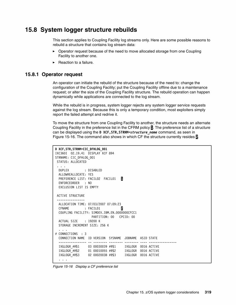
15.8 System logger structure rebuilds
This section applies to Coupling Facility log streams only. Here are some possible reasons to rebuild a structure that contains log stream data:
� Operator request because of the need to move allocated storage from one Coupling Facility to another one.
� Reaction to a failure.
15.8.1 Operator request
An operator can initiate the rebuild of the structure because of the need to: change the configuration of the Coupling Facility; put the Coupling Facility offline due to a maintenance request; or alter the size of the Coupling Facility structure. The rebuild operation can happen dynamically while applications are connected to the log stream.
While the rebuild is in progress, system logger rejects any system logger service requests against the log stream. Because this is only a temporary condition, most exploiters simply report the failed attempt and redrive it.
To move the structure from one Coupling Facility to another, the structure needs an alternate Coupling Facility in the preference list in the CFRM policy 1. The preference list of a structure can be displayed using the D XCF,STR,STRNM=structure_name command, as seen in Figure 15-16. The command also shows in which CF the structure currently resides 2.
Figure 15-16 Display a CF preference list
D XCF,STR,STRNM=CIC_DFHLOG_001 IXC360I 02.19.41 DISPLAY XCF 894 STRNAME: CIC_DFHLOG_001 STATUS: ALLOCATED . . .DUPLEX : DISABLED
ALLOWREALLOCATE: YES PREFERENCE LIST: FACIL02 FACIL01 1 ENFORCEORDER : NO EXCLUSION LIST IS EMPTY ACTIVE STRUCTURE ---------------- ALLOCATION TIME: 07/03/2007 07:09:23 CFNAME : FACIL01 2 COUPLING FACILITY: SIMDEV.IBM.EN.0000000CFCC1 PARTITION: 00 CPCID: 00 ACTUAL SIZE : 19200 K STORAGE INCREMENT SIZE: 256 K . . .
# CONNECTIONS : 3 CONNECTION NAME ID VERSION SYSNAME JOBNAME ASID STATE
---------------- -- -------- -------- -------- ---- ---------------- IXGLOGR_#@$1 03 00030039 #@$1 IXGLOGR 0016 ACTIVE IXGLOGR_#@$2 01 00010055 #@$2 IXGLOGR 0016 ACTIVE IXGLOGR_#@$3 02 0002003B #@$3 IXGLOGR 0016 ACTIVE . . .
Chapter 15. z/OS system logger considerations 319
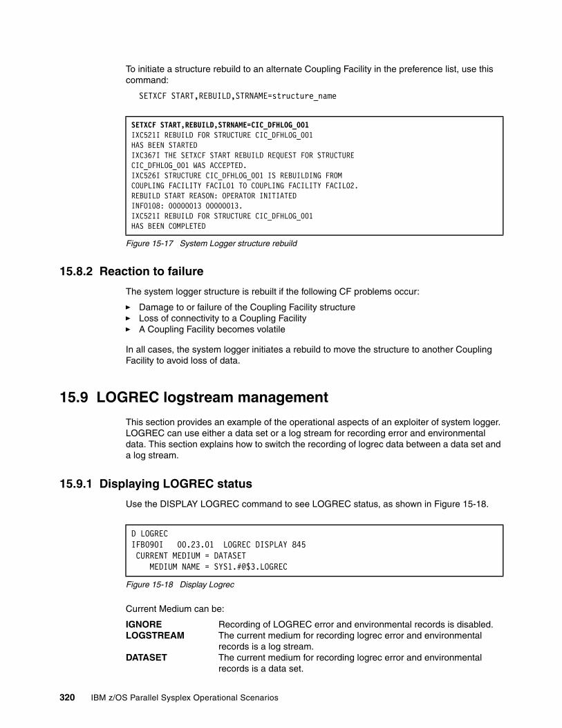
To initiate a structure rebuild to an alternate Coupling Facility in the preference list, use this command:
SETXCF START,REBUILD,STRNAME=structure_name
Figure 15-17 System Logger structure rebuild
15.8.2 Reaction to failure
The system logger structure is rebuilt if the following CF problems occur:
� Damage to or failure of the Coupling Facility structure� Loss of connectivity to a Coupling Facility� A Coupling Facility becomes volatile
In all cases, the system logger initiates a rebuild to move the structure to another Coupling Facility to avoid loss of data.
15.9 LOGREC logstream management
This section provides an example of the operational aspects of an exploiter of system logger. LOGREC can use either a data set or a log stream for recording error and environmental data. This section explains how to switch the recording of logrec data between a data set and a log stream.
15.9.1 Displaying LOGREC status
Use the DISPLAY LOGREC command to see LOGREC status, as shown in Figure 15-18.
Figure 15-18 Display Logrec
Current Medium can be:
IGNORE Recording of LOGREC error and environmental records is disabled.LOGSTREAM The current medium for recording logrec error and environmental
records is a log stream.DATASET The current medium for recording logrec error and environmental
records is a data set.
SETXCF START,REBUILD,STRNAME=CIC_DFHLOG_001 IXC521I REBUILD FOR STRUCTURE CIC_DFHLOG_001 HAS BEEN STARTED IXC367I THE SETXCF START REBUILD REQUEST FOR STRUCTURE CIC_DFHLOG_001 WAS ACCEPTED. IXC526I STRUCTURE CIC_DFHLOG_001 IS REBUILDING FROM COUPLING FACILITY FACIL01 TO COUPLING FACILITY FACIL02.REBUILD START REASON: OPERATOR INITIATED INFO108: 00000013 00000013. IXC521I REBUILD FOR STRUCTURE CIC_DFHLOG_001 HAS BEEN COMPLETED
D LOGREC IFB090I 00.23.01 LOGREC DISPLAY 845 CURRENT MEDIUM = DATASET MEDIUM NAME = SYS1.#@$3.LOGREC
320 IBM z/OS Parallel Sysplex Operational Scenarios
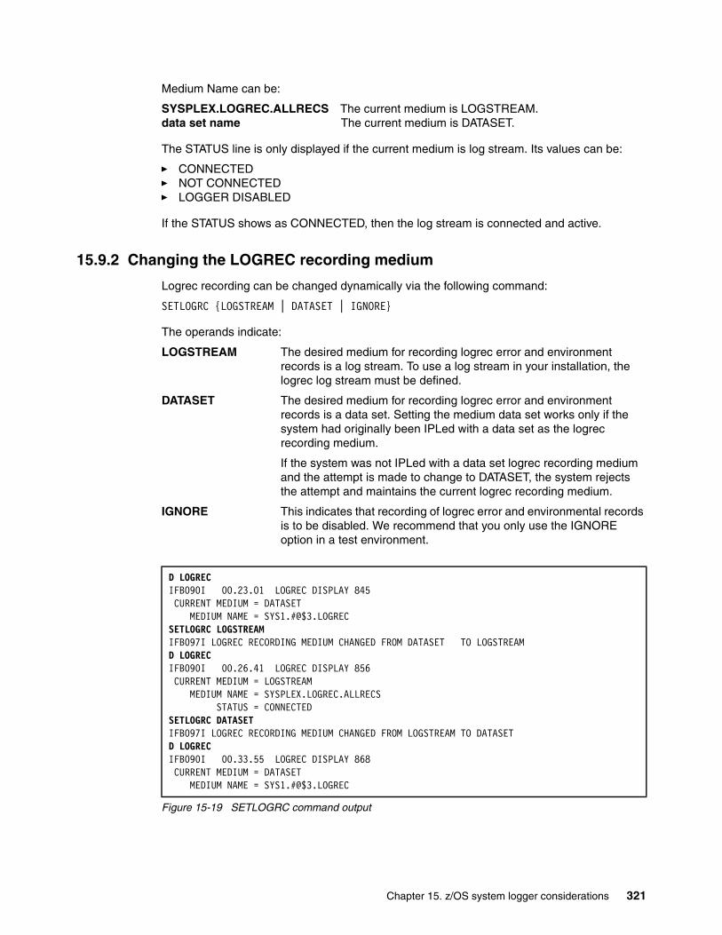
Medium Name can be:
SYSPLEX.LOGREC.ALLRECS The current medium is LOGSTREAM.data set name The current medium is DATASET.
The STATUS line is only displayed if the current medium is log stream. Its values can be:
� CONNECTED� NOT CONNECTED� LOGGER DISABLED
If the STATUS shows as CONNECTED, then the log stream is connected and active.
15.9.2 Changing the LOGREC recording medium
Logrec recording can be changed dynamically via the following command:
SETLOGRC {LOGSTREAM | DATASET | IGNORE}
The operands indicate:
LOGSTREAM The desired medium for recording logrec error and environment records is a log stream. To use a log stream in your installation, the logrec log stream must be defined.
DATASET The desired medium for recording logrec error and environment records is a data set. Setting the medium data set works only if the system had originally been IPLed with a data set as the logrec recording medium.
If the system was not IPLed with a data set logrec recording medium and the attempt is made to change to DATASET, the system rejects the attempt and maintains the current logrec recording medium.
IGNORE This indicates that recording of logrec error and environmental records is to be disabled. We recommend that you only use the IGNORE option in a test environment.
Figure 15-19 SETLOGRC command output
D LOGREC IFB090I 00.23.01 LOGREC DISPLAY 845 CURRENT MEDIUM = DATASET MEDIUM NAME = SYS1.#@$3.LOGREC SETLOGRC LOGSTREAM IFB097I LOGREC RECORDING MEDIUM CHANGED FROM DATASET TO LOGSTREAMD LOGREC IFB090I 00.26.41 LOGREC DISPLAY 856 CURRENT MEDIUM = LOGSTREAM MEDIUM NAME = SYSPLEX.LOGREC.ALLRECS STATUS = CONNECTED SETLOGRC DATASET IFB097I LOGREC RECORDING MEDIUM CHANGED FROM LOGSTREAM TO DATASET D LOGREC IFB090I 00.33.55 LOGREC DISPLAY 868 CURRENT MEDIUM = DATASET MEDIUM NAME = SYS1.#@$3.LOGREC
Chapter 15. z/OS system logger considerations 321

322 IBM z/OS Parallel Sysplex Operational Scenarios
Chapter 16. Network considerations in a Parallel Sysplex
This chapter provides details of operational considerations to keep in mind for the network environment about a Parallel Sysplex environment. It includes:
� Virtual Telecommunications Access Method (VTAM) and its use of Generic Resources (GR)
� TCP/IP
� Sysplex Distributor
� Load Balancing Advisor (LBA)
� IMS Connect
16
© Copyright IBM Corp. 2009. All rights reserved. 323
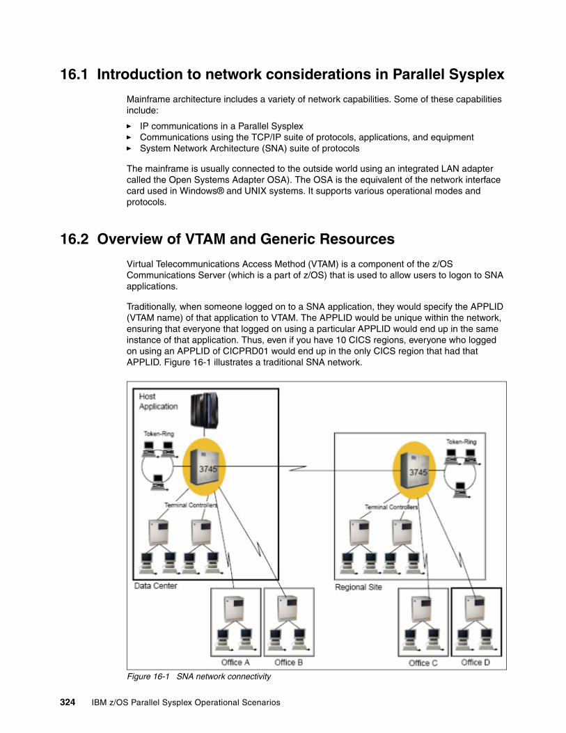
16.1 Introduction to network considerations in Parallel Sysplex
Mainframe architecture includes a variety of network capabilities. Some of these capabilities include:
� IP communications in a Parallel Sysplex� Communications using the TCP/IP suite of protocols, applications, and equipment � System Network Architecture (SNA) suite of protocols
The mainframe is usually connected to the outside world using an integrated LAN adapter called the Open Systems Adapter OSA). The OSA is the equivalent of the network interface card used in Windows® and UNIX systems. It supports various operational modes and protocols.
16.2 Overview of VTAM and Generic Resources
Virtual Telecommunications Access Method (VTAM) is a component of the z/OS Communications Server (which is a part of z/OS) that is used to allow users to logon to SNA applications.
Traditionally, when someone logged on to a SNA application, they would specify the APPLID (VTAM name) of that application to VTAM. The APPLID would be unique within the network, ensuring that everyone that logged on using a particular APPLID would end up in the same instance of that application. Thus, even if you have 10 CICS regions, everyone who logged on using an APPLID of CICPRD01 would end up in the only CICS region that had that APPLID. Figure 16-1 illustrates a traditional SNA network.
Figure 16-1 SNA network connectivity
324 IBM z/OS Parallel Sysplex Operational Scenarios
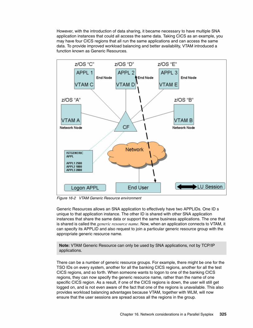
However, with the introduction of data sharing, it became necessary to have multiple SNA application instances that could all access the same data. Taking CICS as an example, you may have four CICS regions that all run the same applications and can access the same data. To provide improved workload balancing and better availability, VTAM introduced a function known as Generic Resources.
Figure 16-2 VTAM Generic Resource environment
Generic Resources allows an SNA application to effectively have two APPLIDs. One ID s unique to that application instance. The other ID is shared with other SNA application instances that share the same data or support the same business applications. The one that is shared is called the generic resource name. Now, when an application connects to VTAM, it can specify its APPLID and also request to join a particular generic resource group with the appropriate generic resource name.
There can be a number of generic resource groups. For example, there might be one for the TSO IDs on every system, another for all the banking CICS regions, another for all the test CICS regions, and so forth. When someone wants to logon to one of the banking CICS regions, they can now specify the generic resource name, rather than the name of one specific CICS region. As a result, if one of the CICS regions is down, the user will still get logged on, and is not even aware of the fact that one of the regions is unavailable. This also provides workload balancing advantages because VTAM, together with WLM, will now ensure that the user sessions are spread across all the regions in the group.
Note: VTAM Generic Resource can only be used by SNA applications, not by TCP/IP applications.
Chapter 16. Network considerations in a Parallel Sysplex 325
VTAM uses a list structure in the Coupling Facility (CF) to hold the information about all the generic resources in the Parallel Sysplex. In the structure, it keeps a list of all the active generic resource groups, the APPLIDs of all the SNA applications that are connected to each of those groups, a list of LUs that are in session with each APPLID, and counts of how many sessions there are with each instance within each group. This information is updated automatically each time a session is established or terminated. The default name for this structure is ISTGENERIC. but you can override the default name by specifying a different structure name on the VTAM STRGR start option (however, it must still begin with IST*).
For VTAM to use the CF, there must be an active CFRM policy defined for the Parallel Sysplex, and the structure must be defined in that policy. All the VTAMs in the Parallel Sysplex that are part of the same generic resource configuration must be connected to the CF containing the structure, as well as all the other CFs indicated by the preference list for the structure. When VTAM in a Parallel Sysplex is started, it automatically attempts to connect to the CF structure, after first checking that the CFRM policy is active. When the first VTAM become active in the Parallel Sysplex, XES will allocate the storage for the CF structure.
The structure disposition is specified as DELETE, which means when the last connector disconnects from the structure, it is deallocated from CF storage.
The connection disposition is specified as KEEP, which means the connection is placed in a failed-persistent state if it terminates. If the connection is failed-persistent, that usually means that the VTAM that disconnected still has data out in the CF.
When one of the VTAMs in the sysplex disconnects from the structure, the remaining VTAMs will normally clean up after that VTAM and remove the connection. If they detect any data that was not deleted, they will leave the connection in a failed-persistent state. In that case, when you issue the VARY NET,CFS command to get VTAM to disconnect from the structure, the other VTAMs detect that the VTAM that disconnected is still active, and therefore do not actually clean up any information relating to that VTAM, so the connection stays in failed-persistent state.
On the other hand, when you actually stop VTAM, the other VTAMs know that it is not active and clean up the entries related to that VTAM. As long as there are no persistent affinities, they will delete the failing VTAM's connection.
The local copy of the generic resource information contained in the VTAM nodes is needed to rebuild the VTAM structure.
When you stop VTAM normally, the connection to the structure will be deleted, unless it is the last connector in the sysplex. If it is the last connector in the sysplex, it will go into a failed-persistent state. This is because there might be persistent information in the structure about affinities between certain applications and generic resources, so VTAM protects that data by keeping the structure.
Because it impacts the availability of applications that use generic resources, you should be aware that VTAM records affinities between application instances and sessions with those instances for any application that has been using a generic resource name. The reason for this is that, if the user initially logs on using a generic resource name, and is routed to CICSA, any subsequent logon attempts should be routed to the same application instance (CICSA).
To be able to do this, VTAM sets a flag for any LU that is using an application that has registered a generic resource name: on any subsequent logon attempt, VTAM checks that flag to see if the logon should be routed to a particular instance. If the VTAM GR function should become unavailable for some reason, VTAM is no longer able to check this information. As a result, it will refuse to set up new sessions with those applications. This is why it is important that you understand how VTAM GR works and how to manage it.
326 IBM z/OS Parallel Sysplex Operational Scenarios
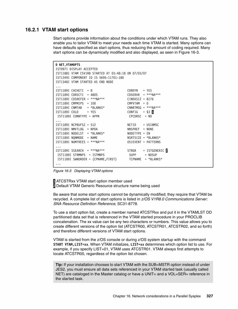
16.2.1 VTAM start options
Start options provide information about the conditions under which VTAM runs. They also enable you to tailor VTAM to meet your needs each time VTAM is started. Many options can have defaults specified as start options, thus reducing the amount of coding required. Many start options can be dynamically modified and also displayed, as seen in Figure 16-3.
Figure 16-3 Displaying VTAM options
1 ATCSTRxx VTAM start option member used 2 Default VTAM Generic Resource structure name being used
Be aware that some start options cannot be dynamically modified; they require that VTAM be recycled. A complete list of start options is listed in z/OS V1R8.0 Communications Server: SNA Resource Definition Reference, SC31-8778.
To use a start option list, create a member named ATCSTRxx and put it in the VTAMLST DD partitioned data set that is referenced in the VTAM started procedure in your PROCLIB concatenation. The xx value can be any two characters or numbers. This value allows you to create different versions of the option list (ATCSTR00, ATCSTR01, ATCSTR02, and so forth) and therefore different versions of VTAM start options.
VTAM is started from the z/OS console or during z/OS system startup with the command START VTAM,LIST=xx. When VTAM initializes, LIST=xx determines which option list to use. For example, if you specify LIST=01, VTAM uses ATCSTR01. VTAM always first attempts to locate ATCSTR00, regardless of the option list chosen.
D NET,VTAMOPTS IST097I DISPLAY ACCEPTED IST1188I VTAM CSV1R8 STARTED AT 03:48:18 ON 07/03/07 IST1349I COMPONENT ID IS 5695-11701-180 IST1348I VTAM STARTED AS END NODE ...IST1189I CACHETI = 8 CDRDYN = YES IST1189I CDRSCTI = 480S CDSERVR = ***NA*** IST1189I CDSREFER = ***NA*** CINDXSIZ = 8176 IST1189I CMPMIPS = 100 CMPVTAM = 0 IST1189I CNMTAB = *BLANKS* CNNRTMSG = ***NA*** IST1189I COLD = YES CONFIG = $3 1 IST1189I CONNTYPE = APPN CPCDRSC = NO ...IST1189I NCPBUFSZ = 512 NETID = USIBMSC IST1189I NMVTLOG = NPDA NNSPREF = NONE IST1189I NODELST = *BLANKS* NODETYPE = EN IST1189I NQNMODE = NAME NSRTSIZE = *BLANKS* IST1189I NUMTREES = ***NA*** OSIEVENT = PATTERNS ...IST1189I SSEARCH = ***NA*** STRGR = ISTGENERIC 2 IST1189I STRMNPS = ISTMNPS SUPP = NOSUP IST1189I SWNORDER = (CPNAME,FIRST) TCPNAME = *BLANKS* ...
Tip: If your installation chooses to start VTAM with the SUB=MSTR option instead of under JES2, you must ensure all data sets referenced in your VTAM started task (usually called NET) are cataloged in the Master catalog or have a UNIT= and a VOL=SER= reference in the started task.
Chapter 16. Network considerations in a Parallel Sysplex 327
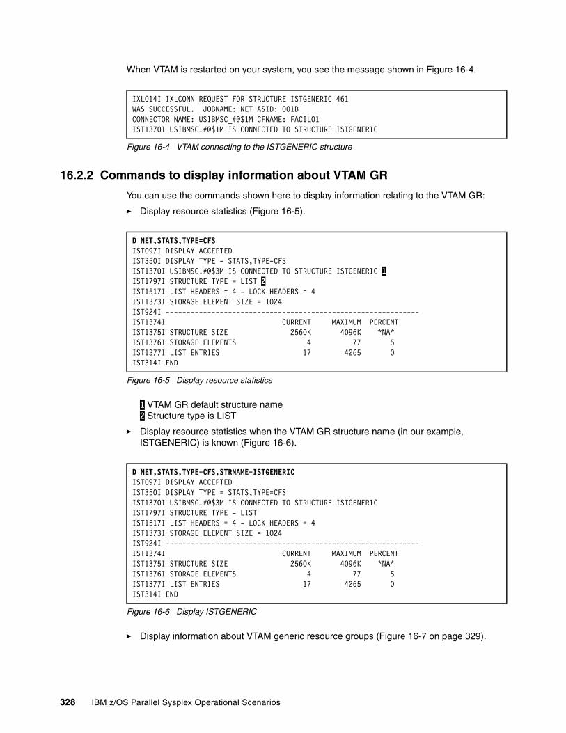
When VTAM is restarted on your system, you see the message shown in Figure 16-4.
Figure 16-4 VTAM connecting to the ISTGENERIC structure
16.2.2 Commands to display information about VTAM GR
You can use the commands shown here to display information relating to the VTAM GR:
� Display resource statistics (Figure 16-5).
Figure 16-5 Display resource statistics
1 VTAM GR default structure name 2 Structure type is LIST
� Display resource statistics when the VTAM GR structure name (in our example, ISTGENERIC) is known (Figure 16-6).
Figure 16-6 Display ISTGENERIC
� Display information about VTAM generic resource groups (Figure 16-7 on page 329).
IXL014I IXLCONN REQUEST FOR STRUCTURE ISTGENERIC 461 WAS SUCCESSFUL. JOBNAME: NET ASID: 001B CONNECTOR NAME: USIBMSC_#@$1M CFNAME: FACIL01 IST1370I USIBMSC.#@$1M IS CONNECTED TO STRUCTURE ISTGENERIC
D NET,STATS,TYPE=CFS IST097I DISPLAY ACCEPTED IST350I DISPLAY TYPE = STATS,TYPE=CFS IST1370I USIBMSC.#@$3M IS CONNECTED TO STRUCTURE ISTGENERIC 1IST1797I STRUCTURE TYPE = LIST 2 IST1517I LIST HEADERS = 4 - LOCK HEADERS = 4 IST1373I STORAGE ELEMENT SIZE = 1024 IST924I ------------------------------------------------------------- IST1374I CURRENT MAXIMUM PERCENT IST1375I STRUCTURE SIZE 2560K 4096K *NA* IST1376I STORAGE ELEMENTS 4 77 5 IST1377I LIST ENTRIES 17 4265 0 IST314I END
D NET,STATS,TYPE=CFS,STRNAME=ISTGENERIC IST097I DISPLAY ACCEPTED IST350I DISPLAY TYPE = STATS,TYPE=CFS IST1370I USIBMSC.#@$3M IS CONNECTED TO STRUCTURE ISTGENERIC IST1797I STRUCTURE TYPE = LIST IST1517I LIST HEADERS = 4 - LOCK HEADERS = 4 IST1373I STORAGE ELEMENT SIZE = 1024 IST924I ------------------------------------------------------------- IST1374I CURRENT MAXIMUM PERCENT IST1375I STRUCTURE SIZE 2560K 4096K *NA* IST1376I STORAGE ELEMENTS 4 77 5 IST1377I LIST ENTRIES 17 4265 0 IST314I END
328 IBM z/OS Parallel Sysplex Operational Scenarios
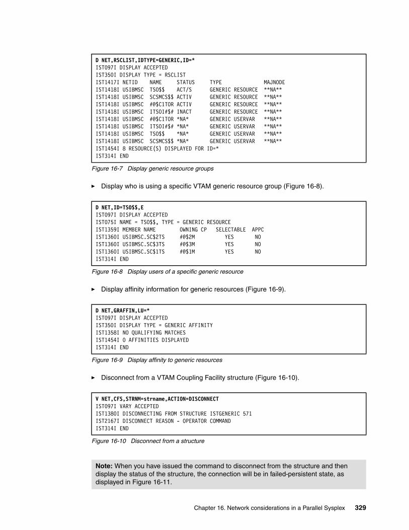
Figure 16-7 Display generic resource groups
� Display who is using a specific VTAM generic resource group (Figure 16-8).
Figure 16-8 Display users of a specific generic resource
� Display affinity information for generic resources (Figure 16-9).
Figure 16-9 Display affinity to generic resources
� Disconnect from a VTAM Coupling Facility structure (Figure 16-10).
Figure 16-10 Disconnect from a structure
D NET,RSCLIST,IDTYPE=GENERIC,ID=* IST097I DISPLAY ACCEPTED IST350I DISPLAY TYPE = RSCLIST IST1417I NETID NAME STATUS TYPE MAJNODE IST1418I USIBMSC TSO$$ ACT/S GENERIC RESOURCE **NA** IST1418I USIBMSC SCSMCS$$ ACTIV GENERIC RESOURCE **NA** IST1418I USIBMSC #@$C1TOR ACTIV GENERIC RESOURCE **NA** IST1418I USIBMSC ITSOI#$# INACT GENERIC RESOURCE **NA** IST1418I USIBMSC #@$C1TOR *NA* GENERIC USERVAR **NA** IST1418I USIBMSC ITSOI#$# *NA* GENERIC USERVAR **NA** IST1418I USIBMSC TSO$$ *NA* GENERIC USERVAR **NA** IST1418I USIBMSC SCSMCS$$ *NA* GENERIC USERVAR **NA** IST1454I 8 RESOURCE(S) DISPLAYED FOR ID=* IST314I END
D NET,ID=TSO$$,E IST097I DISPLAY ACCEPTED IST075I NAME = TSO$$, TYPE = GENERIC RESOURCE IST1359I MEMBER NAME OWNING CP SELECTABLE APPC IST1360I USIBMSC.SC$2TS #@$2M YES NO IST1360I USIBMSC.SC$3TS #@$3M YES NO IST1360I USIBMSC.SC$1TS #@$1M YES NO IST314I END
D NET,GRAFFIN,LU=* IST097I DISPLAY ACCEPTED IST350I DISPLAY TYPE = GENERIC AFFINITY IST1358I NO QUALIFYING MATCHES IST1454I 0 AFFINITIES DISPLAYED IST314I END
V NET,CFS,STRNM=strname,ACTION=DISCONNECTIST097I VARY ACCEPTED IST1380I DISCONNECTING FROM STRUCTURE ISTGENERIC 571 IST2167I DISCONNECT REASON - OPERATOR COMMAND IST314I END
Note: When you have issued the command to disconnect from the structure and then display the status of the structure, the connection will be in failed-persistent state, as displayed in Figure 16-11.
Chapter 16. Network considerations in a Parallel Sysplex 329
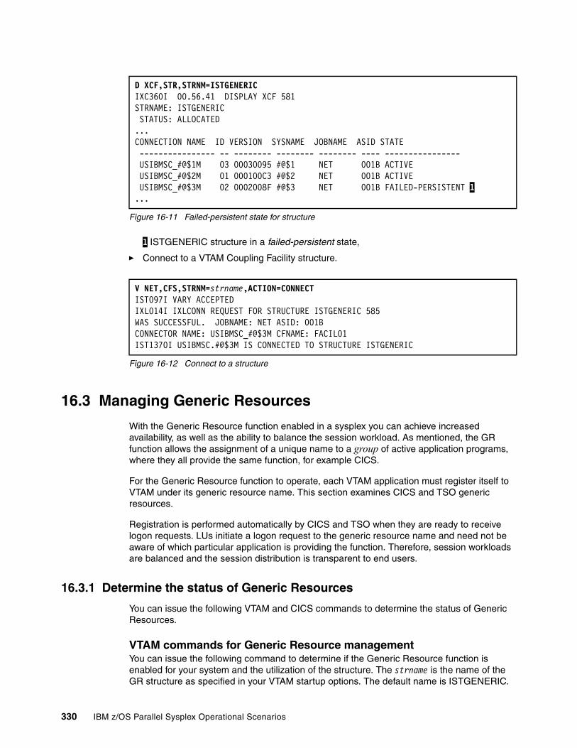
Figure 16-11 Failed-persistent state for structure
1 ISTGENERIC structure in a failed-persistent state,
� Connect to a VTAM Coupling Facility structure.
Figure 16-12 Connect to a structure
16.3 Managing Generic Resources
With the Generic Resource function enabled in a sysplex you can achieve increased availability, as well as the ability to balance the session workload. As mentioned, the GR function allows the assignment of a unique name to a group of active application programs, where they all provide the same function, for example CICS.
For the Generic Resource function to operate, each VTAM application must register itself to VTAM under its generic resource name. This section examines CICS and TSO generic resources.
Registration is performed automatically by CICS and TSO when they are ready to receive logon requests. LUs initiate a logon request to the generic resource name and need not be aware of which particular application is providing the function. Therefore, session workloads are balanced and the session distribution is transparent to end users.
16.3.1 Determine the status of Generic Resources
You can issue the following VTAM and CICS commands to determine the status of Generic Resources.
VTAM commands for Generic Resource managementYou can issue the following command to determine if the Generic Resource function is enabled for your system and the utilization of the structure. The strname is the name of the GR structure as specified in your VTAM startup options. The default name is ISTGENERIC.
D XCF,STR,STRNM=ISTGENERIC IXC360I 00.56.41 DISPLAY XCF 581 STRNAME: ISTGENERIC STATUS: ALLOCATED ...CONNECTION NAME ID VERSION SYSNAME JOBNAME ASID STATE ---------------- -- -------- -------- -------- ---- ---------------- USIBMSC_#@$1M 03 00030095 #@$1 NET 001B ACTIVE USIBMSC_#@$2M 01 000100C3 #@$2 NET 001B ACTIVE USIBMSC_#@$3M 02 0002008F #@$3 NET 001B FAILED-PERSISTENT 1...
V NET,CFS,STRNM=strname,ACTION=CONNECTIST097I VARY ACCEPTED IXL014I IXLCONN REQUEST FOR STRUCTURE ISTGENERIC 585 WAS SUCCESSFUL. JOBNAME: NET ASID: 001B CONNECTOR NAME: USIBMSC_#@$3M CFNAME: FACIL01 IST1370I USIBMSC.#@$3M IS CONNECTED TO STRUCTURE ISTGENERIC
330 IBM z/OS Parallel Sysplex Operational Scenarios
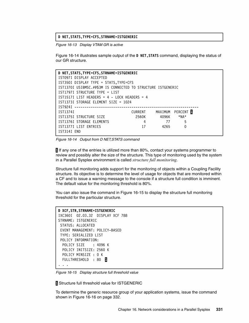
Figure 16-13 Display VTAM GR is active
Figure 16-14 illustrates sample output of the D NET,STATS command, displaying the status of our GR structure.
Figure 16-14 Output from D NET,STATS command
1 If any one of the entries is utilized more than 80%, contact your systems programmer to review and possibly alter the size of the structure. This type of monitoring used by the system in a Parallel Sysplex environment is called structure full monitoring.
Structure full monitoring adds support for the monitoring of objects within a Coupling Facility structure. Its objective is to determine the level of usage for objects that are monitored within a CF and to issue a warning message to the console if a structure full condition is imminent. The default value for the monitoring threshold is 80%.
You can also issue the command in Figure 16-15 to display the structure full monitoring threshold for the particular structure.
Figure 16-15 Display structure full threshold value
1 Structure full threshold value for ISTGENERIC
To determine the generic resource group of your application systems, issue the command shown in Figure 16-16 on page 332.
D NET,STATS,TYPE=CFS,STRNAME=ISTGENERIC
D NET,STATS,TYPE=CFS,STRNAME=ISTGENERIC IST097I DISPLAY ACCEPTED IST350I DISPLAY TYPE = STATS,TYPE=CFS IST1370I USIBMSC.#@$3M IS CONNECTED TO STRUCTURE ISTGENERIC IST1797I STRUCTURE TYPE = LIST IST1517I LIST HEADERS = 4 - LOCK HEADERS = 4 IST1373I STORAGE ELEMENT SIZE = 1024 IST924I ------------------------------------------------------------- IST1374I CURRENT MAXIMUM PERCENT 1IST1375I STRUCTURE SIZE 2560K 4096K *NA* IST1376I STORAGE ELEMENTS 4 77 5 IST1377I LIST ENTRIES 17 4265 0 IST314I END
D XCF,STR,STRNAME=ISTGENERIC IXC360I 02.03.32 DISPLAY XCF 788 STRNAME: ISTGENERIC STATUS: ALLOCATED EVENT MANAGEMENT: POLICY-BASED TYPE: SERIALIZED LIST POLICY INFORMATION: POLICY SIZE : 4096 K POLICY INITSIZE: 2560 K POLICY MINSIZE : 0 K FULLTHRESHOLD : 80 1 . . .
Chapter 16. Network considerations in a Parallel Sysplex 331
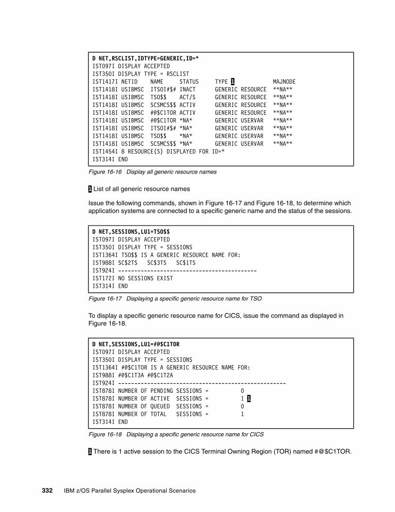
Figure 16-16 Display all generic resource names
1 List of all generic resource names
Issue the following commands, shown in Figure 16-17 and Figure 16-18, to determine which application systems are connected to a specific generic name and the status of the sessions.
Figure 16-17 Displaying a specific generic resource name for TSO
To display a specific generic resource name for CICS, issue the command as displayed in Figure 16-18.
Figure 16-18 Displaying a specific generic resource name for CICS
1 There is 1 active session to the CICS Terminal Owning Region (TOR) named #@$C1TOR.
D NET,RSCLIST,IDTYPE=GENERIC,ID=*IST097I DISPLAY ACCEPTED IST350I DISPLAY TYPE = RSCLIST IST1417I NETID NAME STATUS TYPE 1 MAJNODE IST1418I USIBMSC ITSOI#$# INACT GENERIC RESOURCE **NA** IST1418I USIBMSC TSO$$ ACT/S GENERIC RESOURCE **NA** IST1418I USIBMSC SCSMCS$$ ACTIV GENERIC RESOURCE **NA** IST1418I USIBMSC #@$C1TOR ACTIV GENERIC RESOURCE **NA** IST1418I USIBMSC #@$C1TOR *NA* GENERIC USERVAR **NA** IST1418I USIBMSC ITSOI#$# *NA* GENERIC USERVAR **NA** IST1418I USIBMSC TSO$$ *NA* GENERIC USERVAR **NA** IST1418I USIBMSC SCSMCS$$ *NA* GENERIC USERVAR **NA** IST1454I 8 RESOURCE(S) DISPLAYED FOR ID=* IST314I END
D NET,SESSIONS,LU1=TSO$$ IST097I DISPLAY ACCEPTED IST350I DISPLAY TYPE = SESSIONS IST1364I TSO$$ IS A GENERIC RESOURCE NAME FOR: IST988I SC$2TS SC$3TS SC$1TS IST924I -------------------------------------------IST172I NO SESSIONS EXIST IST314I END
D NET,SESSIONS,LU1=#@$C1TOR IST097I DISPLAY ACCEPTED IST350I DISPLAY TYPE = SESSIONS IST1364I #@$C1TOR IS A GENERIC RESOURCE NAME FOR: IST988I #@$C1T3A #@$C1T2A IST924I ----------------------------------------------------IST878I NUMBER OF PENDING SESSIONS = 0 IST878I NUMBER OF ACTIVE SESSIONS = 1 1IST878I NUMBER OF QUEUED SESSIONS = 0 IST878I NUMBER OF TOTAL SESSIONS = 1 IST314I END
332 IBM z/OS Parallel Sysplex Operational Scenarios
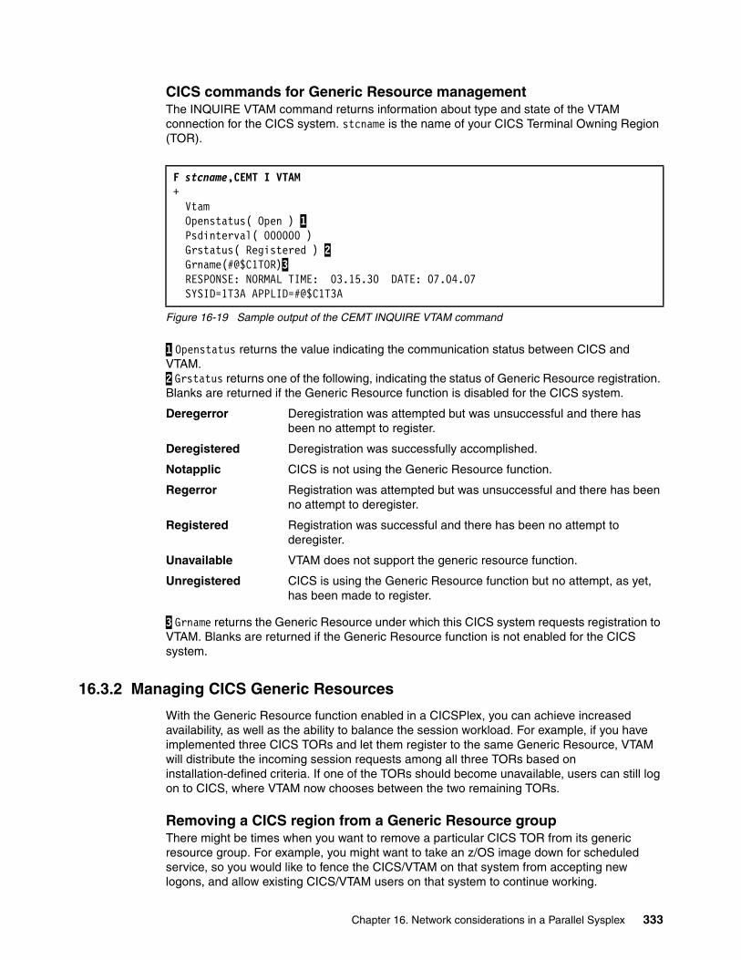
CICS commands for Generic Resource managementThe INQUIRE VTAM command returns information about type and state of the VTAM connection for the CICS system. stcname is the name of your CICS Terminal Owning Region (TOR).
Figure 16-19 Sample output of the CEMT INQUIRE VTAM command
1 Openstatus returns the value indicating the communication status between CICS and VTAM. 2 Grstatus returns one of the following, indicating the status of Generic Resource registration. Blanks are returned if the Generic Resource function is disabled for the CICS system.
Deregerror Deregistration was attempted but was unsuccessful and there has been no attempt to register.
Deregistered Deregistration was successfully accomplished.
Notapplic CICS is not using the Generic Resource function.
Regerror Registration was attempted but was unsuccessful and there has been no attempt to deregister.
Registered Registration was successful and there has been no attempt to deregister.
Unavailable VTAM does not support the generic resource function.
Unregistered CICS is using the Generic Resource function but no attempt, as yet, has been made to register.
3 Grname returns the Generic Resource under which this CICS system requests registration to VTAM. Blanks are returned if the Generic Resource function is not enabled for the CICS system.
16.3.2 Managing CICS Generic Resources
With the Generic Resource function enabled in a CICSPlex, you can achieve increased availability, as well as the ability to balance the session workload. For example, if you have implemented three CICS TORs and let them register to the same Generic Resource, VTAM will distribute the incoming session requests among all three TORs based on installation-defined criteria. If one of the TORs should become unavailable, users can still log on to CICS, where VTAM now chooses between the two remaining TORs.
Removing a CICS region from a Generic Resource groupThere might be times when you want to remove a particular CICS TOR from its generic resource group. For example, you might want to take an z/OS image down for scheduled service, so you would like to fence the CICS/VTAM on that system from accepting new logons, and allow existing CICS/VTAM users on that system to continue working.
F stcname,CEMT I VTAM + Vtam Openstatus( Open ) 1 Psdinterval( 000000 ) Grstatus( Registered ) 2 Grname(#@$C1TOR)3 RESPONSE: NORMAL TIME: 03.15.30 DATE: 07.04.07 SYSID=1T3A APPLID=#@$C1T3A
Chapter 16. Network considerations in a Parallel Sysplex 333
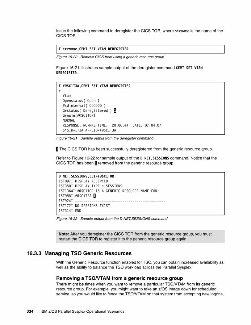
Issue the following command to deregister the CICS TOR, where stcname is the name of the CICS TOR.
Figure 16-20 Remove CICS from using a generic resource group
Figure 16-21 illustrates sample output of the deregister command CEMT SET VTAM DEREGISTER.
Figure 16-21 Sample output from the deregister command
1 The CICS TOR has been successfully deregistered from the generic resource group.
Refer to Figure 16-22 for sample output of the D NET,SESSIONS command. Notice that the CICS TOR has been 1 removed from the generic resource group.
Figure 16-22 Sample output from the D NET,SESSIONS command
16.3.3 Managing TSO Generic Resources
With the Generic Resource function enabled for TSO, you can obtain increased availability as well as the ability to balance the TSO workload across the Parallel Sysplex.
Removing a TSO/VTAM from a generic resource groupThere might be times when you want to remove a particular TSO/VTAM from its generic resource group. For example, you might want to take an z/OS image down for scheduled service, so you would like to fence the TSO/VTAM on that system from accepting new logons,
F stcname,CEMT SET VTAM DEREGISTER
F #@$C1T3A,CEMT SET VTAM DEREGISTER + Vtam Openstatus( Open ) Psdinterval( 000000 ) Grstatus( Deregistered ) 1 Grname(#@$C1TOR) NORMAL RESPONSE: NORMAL TIME: 20.06.44 DATE: 07.04.07 SYSID=1T3A APPLID=#@$C1T3A
D NET,SESSIONS,LU1=#@$C1TOR IST097I DISPLAY ACCEPTED IST350I DISPLAY TYPE = SESSIONS IST1364I #@$C1TOR IS A GENERIC RESOURCE NAME FOR: IST988I #@$C1T2A 1IST924I --------------------------------------------IST172I NO SESSIONS EXIST IST314I END
Note: After you deregister the CICS TOR from the generic resource group, you must restart the CICS TOR to register it to the generic resource group again.
334 IBM z/OS Parallel Sysplex Operational Scenarios
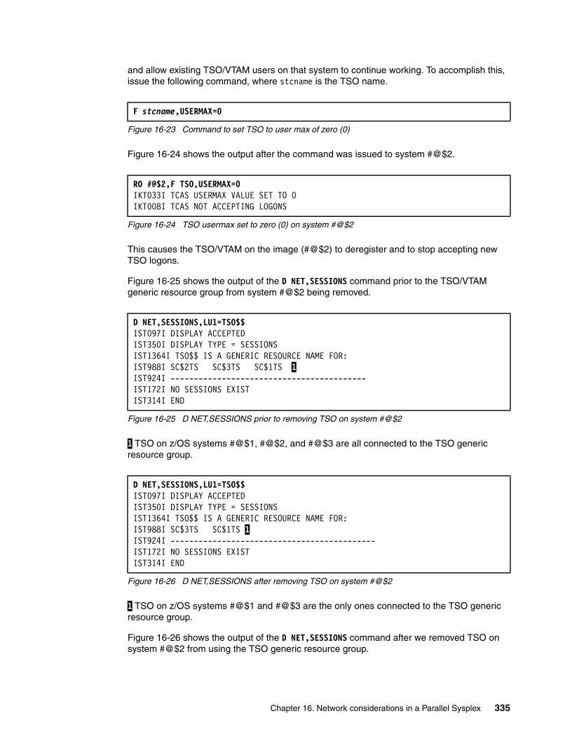
and allow existing TSO/VTAM users on that system to continue working. To accomplish this, issue the following command, where stcname is the TSO name.
Figure 16-23 Command to set TSO to user max of zero (0)
Figure 16-24 shows the output after the command was issued to system #@$2.
Figure 16-24 TSO usermax set to zero (0) on system #@$2
This causes the TSO/VTAM on the image (#@$2) to deregister and to stop accepting new TSO logons.
Figure 16-25 shows the output of the D NET,SESSIONS command prior to the TSO/VTAM generic resource group from system #@$2 being removed.
Figure 16-25 D NET,SESSIONS prior to removing TSO on system #@$2
1 TSO on z/OS systems #@$1, #@$2, and #@$3 are all connected to the TSO generic resource group.
Figure 16-26 D NET,SESSIONS after removing TSO on system #@$2
1 TSO on z/OS systems #@$1 and #@$3 are the only ones connected to the TSO generic resource group.
Figure 16-26 shows the output of the D NET,SESSIONS command after we removed TSO on system #@$2 from using the TSO generic resource group.
F stcname,USERMAX=0
RO #@$2,F TSO,USERMAX=0 IKT033I TCAS USERMAX VALUE SET TO 0 IKT008I TCAS NOT ACCEPTING LOGONS
D NET,SESSIONS,LU1=TSO$$ IST097I DISPLAY ACCEPTED IST350I DISPLAY TYPE = SESSIONS IST1364I TSO$$ IS A GENERIC RESOURCE NAME FOR: IST988I SC$2TS SC$3TS SC$1TS 1 IST924I ------------------------------------------IST172I NO SESSIONS EXIST IST314I END
D NET,SESSIONS,LU1=TSO$$ IST097I DISPLAY ACCEPTED IST350I DISPLAY TYPE = SESSIONS IST1364I TSO$$ IS A GENERIC RESOURCE NAME FOR: IST988I SC$3TS SC$1TS 1 IST924I --------------------------------------------IST172I NO SESSIONS EXIST IST314I END
Chapter 16. Network considerations in a Parallel Sysplex 335
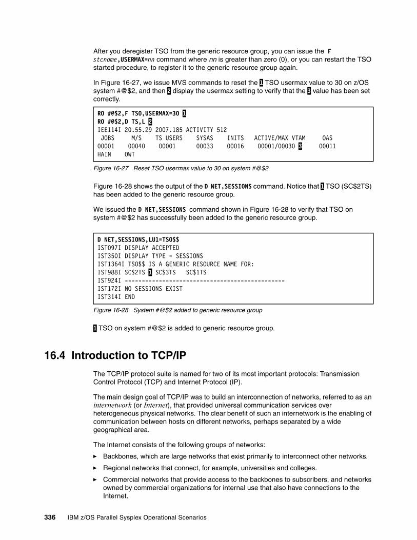
After you deregister TSO from the generic resource group, you can issue the F stcname,USERMAX=nn command where nn is greater than zero (0), or you can restart the TSO started procedure, to register it to the generic resource group again.
In Figure 16-27, we issue MVS commands to reset the 1 TSO usermax value to 30 on z/OS system #@$2, and then 2 display the usermax setting to verify that the 3 value has been set correctly.
Figure 16-27 Reset TSO usermax value to 30 on system #@$2
Figure 16-28 shows the output of the D NET,SESSIONS command. Notice that 1 TSO (SC$2TS) has been added to the generic resource group.
We issued the D NET,SESSIONS command shown in Figure 16-28 to verify that TSO on system #@$2 has successfully been added to the generic resource group.
Figure 16-28 System #@$2 added to generic resource group
1 TSO on system #@$2 is added to generic resource group.
16.4 Introduction to TCP/IP
The TCP/IP protocol suite is named for two of its most important protocols: Transmission Control Protocol (TCP) and Internet Protocol (IP).
The main design goal of TCP/IP was to build an interconnection of networks, referred to as an internetwork (or Internet), that provided universal communication services over heterogeneous physical networks. The clear benefit of such an internetwork is the enabling of communication between hosts on different networks, perhaps separated by a wide geographical area.
The Internet consists of the following groups of networks:
� Backbones, which are large networks that exist primarily to interconnect other networks.
� Regional networks that connect, for example, universities and colleges.
� Commercial networks that provide access to the backbones to subscribers, and networks owned by commercial organizations for internal use that also have connections to the Internet.
RO #@$2,F TSO,USERMAX=30 1 RO #@$2,D TS,L 2 IEE114I 20.55.29 2007.185 ACTIVITY 512 JOBS M/S TS USERS SYSAS INITS ACTIVE/MAX VTAM OAS 00001 00040 00001 00033 00016 00001/00030 3 00011 HAIN OWT
D NET,SESSIONS,LU1=TSO$$ IST097I DISPLAY ACCEPTED IST350I DISPLAY TYPE = SESSIONS IST1364I TSO$$ IS A GENERIC RESOURCE NAME FOR: IST988I SC$2TS 1 SC$3TS SC$1TS IST924I -----------------------------------------------IST172I NO SESSIONS EXIST IST314I END
336 IBM z/OS Parallel Sysplex Operational Scenarios
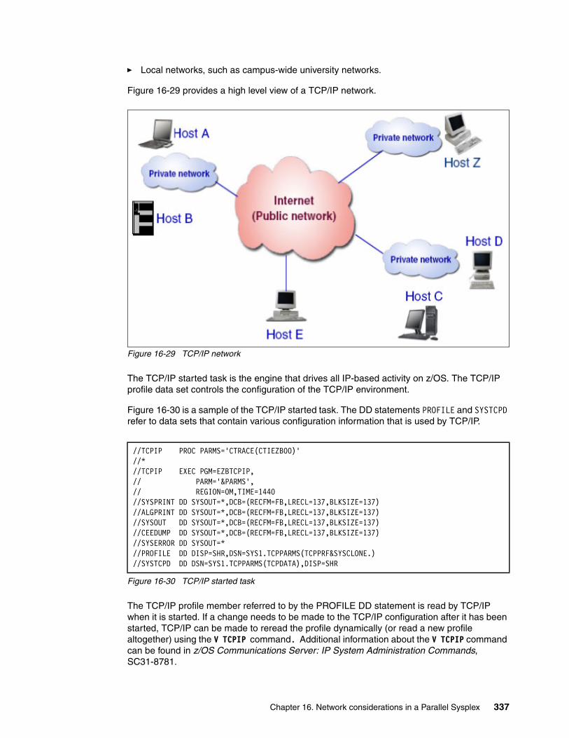
� Local networks, such as campus-wide university networks.
Figure 16-29 provides a high level view of a TCP/IP network.
Figure 16-29 TCP/IP network
The TCP/IP started task is the engine that drives all IP-based activity on z/OS. The TCP/IP profile data set controls the configuration of the TCP/IP environment.
Figure 16-30 is a sample of the TCP/IP started task. The DD statements PROFILE and SYSTCPD refer to data sets that contain various configuration information that is used by TCP/IP.
Figure 16-30 TCP/IP started task
The TCP/IP profile member referred to by the PROFILE DD statement is read by TCP/IP when it is started. If a change needs to be made to the TCP/IP configuration after it has been started, TCP/IP can be made to reread the profile dynamically (or read a new profile altogether) using the V TCPIP command. Additional information about the V TCPIP command can be found in z/OS Communications Server: IP System Administration Commands, SC31-8781.
//TCPIP PROC PARMS='CTRACE(CTIEZB00)' //* //TCPIP EXEC PGM=EZBTCPIP, // PARM='&PARMS', // REGION=0M,TIME=1440 //SYSPRINT DD SYSOUT=*,DCB=(RECFM=FB,LRECL=137,BLKSIZE=137)//ALGPRINT DD SYSOUT=*,DCB=(RECFM=FB,LRECL=137,BLKSIZE=137)//SYSOUT DD SYSOUT=*,DCB=(RECFM=FB,LRECL=137,BLKSIZE=137)//CEEDUMP DD SYSOUT=*,DCB=(RECFM=FB,LRECL=137,BLKSIZE=137)//SYSERROR DD SYSOUT=* //PROFILE DD DISP=SHR,DSN=SYS1.TCPPARMS(TCPPRF&SYSCLONE.) //SYSTCPD DD DSN=SYS1.TCPPARMS(TCPDATA),DISP=SHR
Chapter 16. Network considerations in a Parallel Sysplex 337
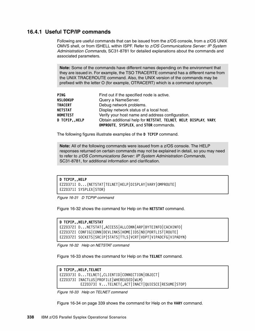
16.4.1 Useful TCP/IP commands
Following are useful commands that can be issued from the z/OS console, from a z/OS UNIX OMVS shell, or from ISHELL within ISPF. Refer to z/OS Communications Server: IP System Administration Commands, SC31-8781 for detailed explanations about the commands and associated parameters.
PING Find out if the specified node is active.NSLOOKUP Query a NameServer.TRACERT Debug network problems.NETSTAT Display network status of a local host.HOMETEST Verify your host name and address configuration.D TCPIP,,HELP Obtain additional help for NETSTAT, TELNET, HELP, DISPLAY, VARY,
OMPROUTE, SYSPLEX, and STOR commands.
The following figures illustrate examples of the D TCPIP command.
Figure 16-31 D TCPIP command
Figure 16-32 shows the command for Help on the NETSTAT command.
Figure 16-32 Help on NETSTAT command
Figure 16-33 shows the command for Help on the TELNET command.
Figure 16-33 Help on TELNET command
Figure 16-34 on page 339 shows the command for Help on the VARY command.
Note: Some of the commands have different names depending on the environment that they are issued in. For example, the TSO TRACERTE command has a different name from the UNIX TRACEROUTE command. Also, the UNIX version of the commands may be prefixed with the letter O (for example, OTRACERT) which is a command synonym.
Note: All of the following commands were issued from a z/OS console. The HELP responses returned on certain commands may not be explained in detail, so you may need to refer to z/OS Communications Server: IP System Administration Commands, SC31-8781, for additional information and clarification.
D TCPIP,,HELP EZZ0371I D...(NETSTAT|TELNET|HELP|DISPLAY|VARY|OMPROUTE| EZZ0371I SYSPLEX|STOR)
D TCPIP,,HELP,NETSTAT EZZ0372I D...NETSTAT(,ACCESS|ALLCONN|ARP|BYTEINFO|CACHINFO| EZZ0372I CONFIG|CONN|DEVLINKS|HOME|IDS|ND|PORTLIST|ROUTE| EZZ0372I SOCKETS|SRCIP|STATS|TTLS|VCRT|VDPT|VIPADCFG|VIPADYN)
D TCPIP,,HELP,TELNET EZZ0373I D...TELNET(,CLIENTID|CONNECTION|OBJECT| EZZ0373I INACTLUS|PROFILE|WHEREUSED|WLM) EZZ0373I V...TELNET(,ACT|INACT|QUIESCE|RESUME|STOP)
338 IBM z/OS Parallel Sysplex Operational Scenarios
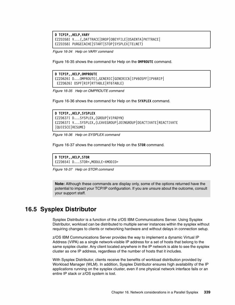
Figure 16-34 Help on VARY command
Figure 16-35 shows the command for Help on the OMPROUTE command.
Figure 16-35 Help on OMPROUTE command
Figure 16-36 shows the command for Help on the SYXPLEX command.
Figure 16-36 Help on SYSPLEX command
Figure 16-37 shows the command for Help on the STOR command.
Figure 16-37 Help on STOR command
16.5 Sysplex Distributor
Sysplex Distributor is a function of the z/OS IBM Communications Server. Using Sysplex Distributor, workload can be distributed to multiple server instances within the sysplex without requiring changes to clients or networking hardware and without delays in connection setup.
z/OS IBM Communications Server provides the way to implement a dynamic Virtual IP Address (VIPA) as a single network-visible IP address for a set of hosts that belong to the same sysplex cluster. Any client located anywhere in the IP network is able to see the sysplex cluster as one IP address, regardless of the number of hosts that it includes.
With Sysplex Distributor, clients receive the benefits of workload distribution provided by Workload Manager (WLM). In addition, Sysplex Distributor ensures high availability of the IP applications running on the sysplex cluster, even if one physical network interface fails or an entire IP stack or z/OS system is lost.
D TCPIP,,HELP,VARY EZZ0358I V...(,DATTRACE|DROP|OBEYFILE|OSAENTA|PKTTRACE| EZZ0358I PURGECACHE|START|STOP|SYSPLEX|TELNET)
D TCPIP,,HELP,OMPROUTE EZZ0626I D...OMPROUTE(,GENERIC|GENERIC6|IPV6OSPF|IPV6RIP| EZZ0626I OSPF|RIP|RTTABLE|RT6TABLE)
D TCPIP,,HELP,SYSPLEX EZZ0637I D...SYSPLEX,(GROUP|VIPADYN) EZZ0637I V...SYSPLEX,(LEAVEGROUP|JOINGROUP|DEACTIVATE|REACTIVATE |QUIESCE|RESUME)
D TCPIP,,HELP,STOR EZZ0654I D...STOR<,MODULE=XMODID>
Note: Although these commands are display only, some of the options returned have the potential to impact your TCP/IP configuration. If you are unsure about the outcome, consult your support staff.
Chapter 16. Network considerations in a Parallel Sysplex 339
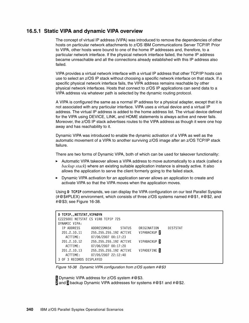
16.5.1 Static VIPA and dynamic VIPA overview
The concept of virtual IP address (VIPA) was introduced to remove the dependencies of other hosts on particular network attachments to z/OS IBM Communications Server TCP/IP. Prior to VIPA, other hosts were bound to one of the home IP addresses and, therefore, to a particular network interface. If the physical network interface failed, the home IP address became unreachable and all the connections already established with this IP address also failed.
VIPA provides a virtual network interface with a virtual IP address that other TCP/IP hosts can use to select an z/OS IP stack without choosing a specific network interface on that stack. If a specific physical network interface fails, the VIPA address remains reachable by other physical network interfaces. Hosts that connect to z/OS IP applications can send data to a VIPA address via whatever path is selected by the dynamic routing protocol.
A VIPA is configured the same as a normal IP address for a physical adapter, except that it is not associated with any particular interface. VIPA uses a virtual device and a virtual IP address. The virtual IP address is added to the home address list. The virtual device defined for the VIPA using DEVICE, LINK, and HOME statements is always active and never fails. Moreover, the z/OS IP stack advertises routes to the VIPA address as though it were one hop away and has reachability to it.
Dynamic VIPA was introduced to enable the dynamic activation of a VIPA as well as the automatic movement of a VIPA to another surviving z/OS image after an z/OS TCP/IP stack failure.
There are two forms of Dynamic VIPA, both of which can be used for takeover functionality:
� Automatic VIPA takeover allows a VIPA address to move automatically to a stack (called a backup stack) where an existing suitable application instance is already active. It also allows the application to serve the client formerly going to the failed stack.
� Dynamic VIPA activation for an application server allows an application to create and activate VIPA so that the VIPA moves when the application moves.
Using D TCPIP commands, we can display the VIPA configuration on our test Parallel Sysplex (#@$#PLEX) environment, which consists of three z/OS systems named #@$1, #@$2, and #@$3; see Figure 16-38.
Figure 16-38 Dynamic VIPA configuration from z/OS system #@$3
1 Dynamic VIPA address for z/OS system #@$3. 2 and 3 backup Dynamic VIPA addresses for systems #@$1 and #@$2.
D TCPIP,,NETSTAT,VIPADYN EZZ2500I NETSTAT CS V1R8 TCPIP 725 DYNAMIC VIPA: IP ADDRESS ADDRESSMASK STATUS ORIGINATION DISTSTAT 201.2.10.11 255.255.255.192 ACTIVE VIPABACKUP 2 ACTTIME: 07/06/2007 00:17:23 201.2.10.12 255.255.255.192 ACTIVE VIPABACKUP 3 ACTTIME: 07/06/2007 00:17:20 201.2.10.13 255.255.255.192 ACTIVE VIPADEFINE 1 ACTTIME: 07/05/2007 22:12:40 3 OF 3 RECORDS DISPLAYED
340 IBM z/OS Parallel Sysplex Operational Scenarios
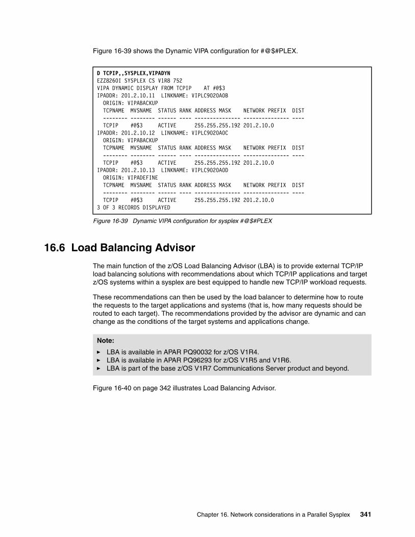
Figure 16-39 shows the Dynamic VIPA configuration for #@$#PLEX.
Figure 16-39 Dynamic VIPA configuration for sysplex #@$#PLEX
16.6 Load Balancing Advisor
The main function of the z/OS Load Balancing Advisor (LBA) is to provide external TCP/IP load balancing solutions with recommendations about which TCP/IP applications and target z/OS systems within a sysplex are best equipped to handle new TCP/IP workload requests.
These recommendations can then be used by the load balancer to determine how to route the requests to the target applications and systems (that is, how many requests should be routed to each target). The recommendations provided by the advisor are dynamic and can change as the conditions of the target systems and applications change.
Figure 16-40 on page 342 illustrates Load Balancing Advisor.
D TCPIP,,SYSPLEX,VIPADYN EZZ8260I SYSPLEX CS V1R8 752 VIPA DYNAMIC DISPLAY FROM TCPIP AT #@$3 IPADDR: 201.2.10.11 LINKNAME: VIPLC9020A0B ORIGIN: VIPABACKUP TCPNAME MVSNAME STATUS RANK ADDRESS MASK NETWORK PREFIX DIST -------- -------- ------ ---- --------------- --------------- ---- TCPIP #@$3 ACTIVE 255.255.255.192 201.2.10.0 IPADDR: 201.2.10.12 LINKNAME: VIPLC9020A0C ORIGIN: VIPABACKUP TCPNAME MVSNAME STATUS RANK ADDRESS MASK NETWORK PREFIX DIST -------- -------- ------ ---- --------------- --------------- ---- TCPIP #@$3 ACTIVE 255.255.255.192 201.2.10.0 IPADDR: 201.2.10.13 LINKNAME: VIPLC9020A0D ORIGIN: VIPADEFINE TCPNAME MVSNAME STATUS RANK ADDRESS MASK NETWORK PREFIX DIST -------- -------- ------ ---- --------------- --------------- ---- TCPIP #@$3 ACTIVE 255.255.255.192 201.2.10.0 3 OF 3 RECORDS DISPLAYED
Note:
� LBA is available in APAR PQ90032 for z/OS V1R4. � LBA is available in APAR PQ96293 for z/OS V1R5 and V1R6.� LBA is part of the base z/OS V1R7 Communications Server product and beyond.
Chapter 16. Network considerations in a Parallel Sysplex 341
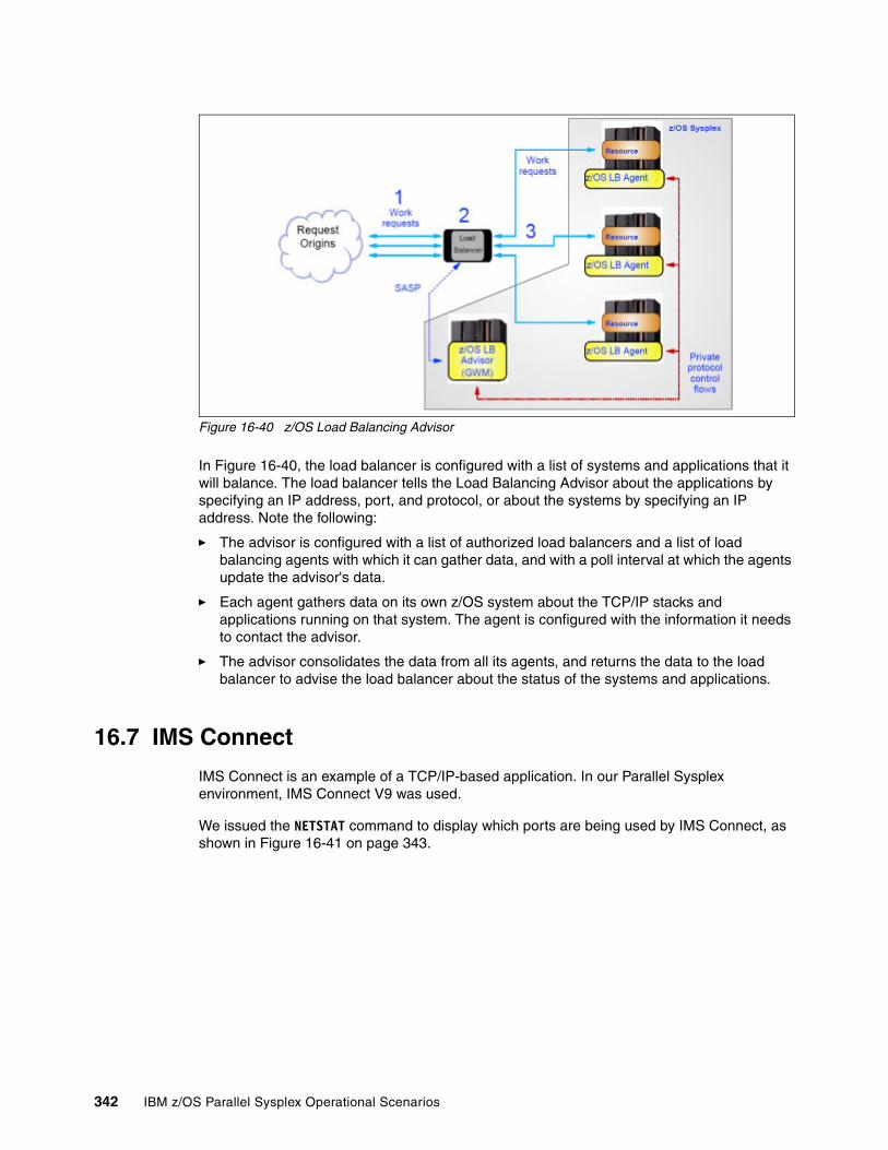
Figure 16-40 z/OS Load Balancing Advisor
In Figure 16-40, the load balancer is configured with a list of systems and applications that it will balance. The load balancer tells the Load Balancing Advisor about the applications by specifying an IP address, port, and protocol, or about the systems by specifying an IP address. Note the following:
� The advisor is configured with a list of authorized load balancers and a list of load balancing agents with which it can gather data, and with a poll interval at which the agents update the advisor's data.
� Each agent gathers data on its own z/OS system about the TCP/IP stacks and applications running on that system. The agent is configured with the information it needs to contact the advisor.
� The advisor consolidates the data from all its agents, and returns the data to the load balancer to advise the load balancer about the status of the systems and applications.
16.7 IMS Connect
IMS Connect is an example of a TCP/IP-based application. In our Parallel Sysplex environment, IMS Connect V9 was used.
We issued the NETSTAT command to display which ports are being used by IMS Connect, as shown in Figure 16-41 on page 343.
342 IBM z/OS Parallel Sysplex Operational Scenarios
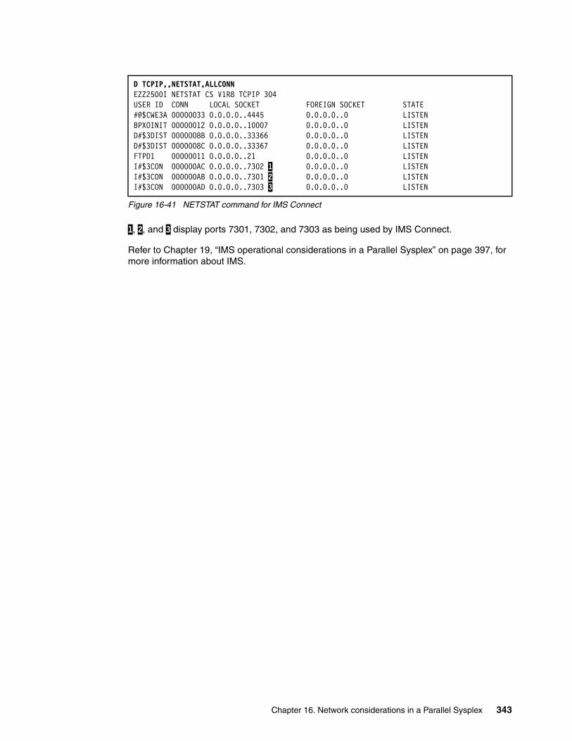
Figure 16-41 NETSTAT command for IMS Connect
1, 2, and 3 display ports 7301, 7302, and 7303 as being used by IMS Connect.
Refer to Chapter 19, “IMS operational considerations in a Parallel Sysplex” on page 397, for more information about IMS.
D TCPIP,,NETSTAT,ALLCONN EZZ2500I NETSTAT CS V1R8 TCPIP 304 USER ID CONN LOCAL SOCKET FOREIGN SOCKET STATE #@$CWE3A 00000033 0.0.0.0..4445 0.0.0.0..0 LISTENBPXOINIT 00000012 0.0.0.0..10007 0.0.0.0..0 LISTEND#$3DIST 0000008B 0.0.0.0..33366 0.0.0.0..0 LISTEND#$3DIST 0000008C 0.0.0.0..33367 0.0.0.0..0 LISTENFTPD1 00000011 0.0.0.0..21 0.0.0.0..0 LISTENI#$3CON 000000AC 0.0.0.0..7302 1 0.0.0.0..0 LISTENI#$3CON 000000AB 0.0.0.0..7301 2 0.0.0.0..0 LISTENI#$3CON 000000AD 0.0.0.0..7303 3 0.0.0.0..0 LISTEN
Chapter 16. Network considerations in a Parallel Sysplex 343

344 IBM z/OS Parallel Sysplex Operational Scenarios
Chapter 17. CICS operational considerations in a Parallel Sysplex
This chapter provides an overview and background information about operational considerations to keep in mind when CICS is used in a Parallel Sysplex. It covers the following topics:
� CICS and Parallel Sysplex
� Multiregion operation (MRO)
� CICS log and journal
� CICS shared temporary storage
� CICS Coupling Facility data table (CFDT)
� CICS named counter server
� CICS and ARM
� CICSPlex System Manager (CPSM)
� What is CICSPlex
17
© Copyright IBM Corp. 2009. All rights reserved. 345
17.1 Introduction to CICS
CICS, or Customer Information Control System, is a transaction processing (TP) monitor that was developed to provide transaction processing for IBM mainframes. TP monitors perform these functions:
� System runtime functions
TP monitors provide an execution environment that ensures the integrity, availability, and security of data, in addition to fast response time and high transaction throughput.
� System administration functions
TP monitors provide administrative support that lets users configure, monitor, and manage their transaction systems.
� Application development functions
TP monitors provide functions for use in custom business applications, including functions to access data, perform intercomputer communications, and design and manage the user interface.
CICS controls the interaction between applications and users and allows programmers to develop window displays without detailed knowledge of the terminals being used. It belongs to the IBM online transaction processing (OLTP) family of products. It is sometimes referred to as a DB/DC (database/data communications) system.
Typical CICS applications include bank ATM transaction processing, library applications, student registration, airline reservations, and so on.
CICS has been called “an operating system within an operating system,” because it has a dispatcher, storage control, task control, file control, and other features. It was designed to allow application programmers to devote their time and effort to the application solution, instead of dwelling on complex programming issues. CICS can be thought of as an interface between its TP applications and the operating system.
17.2 CICS and Parallel Sysplex
A sysplex consists of multiple z/OS systems, coupled together by hardware elements and software services. In a sysplex, z/OS provides a platform of basic multisystem services that applications like CICS can exploit. As an installation's workload grows, additional MVS systems can be added to the sysplex to enable the installation to meet the needs of the greater workload.
To use XCF to communicate in a sysplex, each CICS region joins an XCF group called DFHIR000 by invoking the MVS IXCJOIN macro using services that are provided by the DFHIRP module. The member name for each CICS region is always the CICS APPLID (NETNAME on the CONNECTION resource definition) used for MRO partners.
Each CICS APPLID must be unique within any sysplex, regardless of the MVS levels that are involved. Within the sysplex, CICS regions can communicate only with members of the CICS XCF group (DFHIR000). Figure 17-1 on page 347 illustrates CICS in a Parallel Sysplex environment.
346 IBM z/OS Parallel Sysplex Operational Scenarios
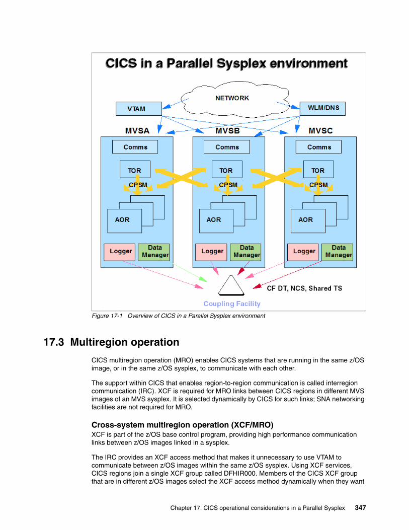
Figure 17-1 Overview of CICS in a Parallel Sysplex environment
17.3 Multiregion operation
CICS multiregion operation (MRO) enables CICS systems that are running in the same z/OS image, or in the same z/OS sysplex, to communicate with each other.
The support within CICS that enables region-to-region communication is called interregion communication (IRC). XCF is required for MRO links between CICS regions in different MVS images of an MVS sysplex. It is selected dynamically by CICS for such links; SNA networking facilities are not required for MRO.
Cross-system multiregion operation (XCF/MRO) XCF is part of the z/OS base control program, providing high performance communication links between z/OS images linked in a sysplex.
The IRC provides an XCF access method that makes it unnecessary to use VTAM to communicate between z/OS images within the same z/OS sysplex. Using XCF services, CICS regions join a single XCF group called DFHIR000. Members of the CICS XCF group that are in different z/OS images select the XCF access method dynamically when they want
Chapter 17. CICS operational considerations in a Parallel Sysplex 347

to talk to each other, overriding the access method specified on the connection resource definition.
Overview of transaction routingCICS transaction routing allows terminals connected to one CICS system to run with transactions in another connected CICS system. This means that you can distribute terminals and transactions around your CICS systems and still have the ability to run any transaction with any terminal.
Figure 17-2 Overview of transaction routing
Figure 17-2 shows a terminal connected to one CICS system running with a user transaction in another CICS system. Communication between the terminal and the user transaction is handled by a CICS-supplied transaction called the relay transaction.
The CICS system that owns the terminal is called the terminal-owning region (TOR). The CICS system that owns the transaction is called the application-owning region (AOR). These terms are not meant to imply that one system owns all the terminals and the other system all the transactions, although this is a possible configuration.
The terminal-owning region and the application-owning region must be connected by MRO or APPC links.
17.4 CICS log and journal
System loggerSystem logger is a set of services that allow an application to write, browse, and delete log data. You can use system logger services to merge data from multiple instances of an application, including merging data from different systems across a sysplex. It uses list structures to hold the logstream data from exploiters of the system logger, such as CICS. For more detail, refer to Chapter 15, “z/OS system logger considerations” on page 307.
CICS logs and journalsIn CICS Transaction Server (TS), the CICS log manager uses the z/OS system logger for all its logging and journaling requirements. Using services provided by the z/OS system logger, the CICS log manager supports:
� The CICS system log, used for transaction backout, emergency restart, and preserving information for resynchronizing an in-doubt unit of work (UOW), even on a cold start. The CICS system log is used for all transaction back-outs.
� Forward recovery logs, auto-journals, user journals, and a log of logs. These are collectively referred to as general logs, to distinguish them from system logs.
348 IBM z/OS Parallel Sysplex Operational Scenarios
For CICS logging, you can use Coupling Facility-based logstreams, DASD only logstreams, or a combination of both. Remember that all connections to DASD only logstreams must come from the same z/OS image, which means you cannot use a DASD only logstream for a user journal that is accessed by CICS regions executing on different z/OS images. For CF-based logstreams, only place logstreams with similar characteristics (such as frequency and size of data written to the logstream) in the same structure.
Monitoring and tuning CICS logstreamsFor monitoring and tuning an existing CICS TS logstream, you can gather the SMF type 88 records and use the sample program SYS1.SAMPLIB(IXGRPT1J) to format the data.
17.4.1 DFHLOG
The DFHLOG logstream is the primary CICS log, often referred to as the CICS System Log. DFHLOG contains transient data relating to an in-progress unit of work. The data contained within the logstream is used for dynamic transaction backout (or backward recovery) and emergency restart. CICS access to data in DFHLOG is provided by system logger.
When CICS is active, it writes information about its transactions to DFHLOG. Periodically CICS tells the system logger to delete the DFHLOG records related to transactions that have completed. If the log structure has been defined with enough space, it is unusual for data from the DFHLOG logstream to be offloaded to a logger offload data set.
DFHLOG logstreams are used exclusively by a single CICS region. You have one DFHLOG logstream per CICS region.
The log streams are accessible from any system that has connectivity to the CF containing the logger structure that references the logstreams. If a z/OS system fails, it is possible to restart the affected CICS regions on another z/OS system, which would still be able to access their DFHLOG data in the CF.
DFHLOG is required for the integrity of CICS transactions. Failed transactions cannot be backed out if no backout information is available in DFHLOG. CICS will stop working if it cannot access the data in the DFHLOG logstream.
17.4.2 DFHSHUNT
The DFHSHUNT logstream is the secondary CICS log, which is also referred to as the CICS SHUNT Log. It contains ongoing data relating to incomplete units of work; the data is used for resynchronizing in-doubt UOWs (even on a cold start). Information or data about long-running transactions is moved (or shunted) from DFHLOG to DFHSHUNT.
The status of a UOW defines whether or not it is removed (shunted) from DFHLOG to the secondary system log, DFHSHUNT. If the status of a unit of work that has failed is at one of the following points, it will be shunted from DFHLOG to DFHSHUNT pending recovery from the failure:
� While in doubt during a two-phase commit process.
� While attempting to commit changes to resources at the end of the UOW.
� While attempting to back out the UOW.
� When the failure that caused the data to be shunted is fixed, the shunted UOW is resolved. This means the data is no longer needed and is discarded.
Chapter 17. CICS operational considerations in a Parallel Sysplex 349

DFHSHUNT logstreams are used exclusively by a single CICS region; you have one DFHSHUNT logstream for EACH CICS region.
17.4.3 USRJRNL
The USERJRNL logstream contains recovery data for user journals where block writes are not forced. A block write is several writes (each being a block) to a logstream that may get grouped together and written as a group rather than being written immediately (block write forced). The USERJRNL structure is optional and was designed primarily to be customized and used by customers to manipulate their own data for other purposes.
17.4.4 General
The GENERAL logstream is another, more basic log that contains recovery data for forward recovery, auto-journaling, and user journals.
17.4.5 Initiating use of the DFHLOG structure
Starting a CICS region will allocate the DFHLOG structure, as illustrated in Figure 17-3.
Figure 17-3 CICS messages when allocating the DFHLOG structure
17.4.6 Deallocating the DFHLOG structure
Stopping the CICS region will deallocate the DFHLOG structure.
17.4.7 Modifying the size of DFHLOG
There may be a requirement to modify the size of the DFHLOG structure due to increased activity resulting in a larger structure. Or, the original structure may be oversized and needs to be decreased.
Perform the following steps using the appropriate z/OS system commands.
1. Check system logger’s view of the DFHLOG structure and notice the association between the structure name and logstream:
D LOGGER,STR,STRNAME=DFHLOG structure name
2. Check the structure's size and location:
D XCF,STR,STRNAME=DFHLOG structure name
3. Check that there is sufficient free space in the current Coupling Facility:
D CF,CFNAME=current CF name
4. Modify the structure size with the ALTER command:
SETXCF START,ALTER,STRNM=DFHLOG structure name,SIZE=new size
DFHLG0103I #@$C1T1A System log (DFHLOG) initialization has started. DFHLG0104I #@$C1T1A 506 System log (DFHLOG) initialization has ended. Log stream #@$C.#@$C1T1A.DFHLOG2 is connected to structure CIC_DFHLOG_001. DFHLG0103I #@$C1T1A System log (DFHSHUNT) initialization has started.
350 IBM z/OS Parallel Sysplex Operational Scenarios
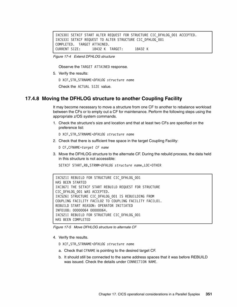
Figure 17-4 Extend DFHLOG structure
Observe the TARGET ATTAINED response.
5. Verify the results:
D XCF,STR,STRNAME=DFHLOG structure name
Check the ACTUAL SIZE value.
17.4.8 Moving the DFHLOG structure to another Coupling Facility
It may become necessary to move a structure from one CF to another to rebalance workload between the CFs or to empty out a CF for maintenance. Perform the following steps using the appropriate z/OS system commands.
1. Check the structure's size and location and that at least two CFs are specified on the preference list:
D XCF,STR,STRNAME=DFHLOG structure name
2. Check that there is sufficient free space in the target Coupling Facility:
D CF,CFNAME=target CF name
3. Move the DFHLOG structure to the alternate CF. During the rebuild process, the data held in this structure is not accessible:
SETXCF START,RB,STRNM=DFHLOG structure name,LOC=OTHER
Figure 17-5 Move DFHLOG structure to alternate CF
4. Verify the results.
D XCF,STR,STRNAME=DFHLOG structure name
a. Check that CFNAME is pointing to the desired target CF.
b. It should still be connected to the same address spaces that it was before REBUILD was issued. Check the details under CONNECTION NAME.
IXC530I SETXCF START ALTER REQUEST FOR STRUCTURE CIC_DFHLOG_001 ACCEPTED.IXC533I SETXCF REQUEST TO ALTER STRUCTURE CIC_DFHLOG_001 COMPLETED. TARGET ATTAINED. CURRENT SIZE: 18432 K TARGET: 18432 K
IXC521I REBUILD FOR STRUCTURE CIC_DFHLOG_001 HAS BEEN STARTED IXC367I THE SETXCF START REBUILD REQUEST FOR STRUCTURE CIC_DFHLOG_001 WAS ACCEPTED. IXC526I STRUCTURE CIC_DFHLOG_001 IS REBUILDING FROM COUPLING FACILITY FACIL02 TO COUPLING FACILITY FACIL01. REBUILD START REASON: OPERATOR INITIATED INFO108: 00000064 00000064. IXC521I REBUILD FOR STRUCTURE CIC_DFHLOG_001 HAS BEEN COMPLETED
Chapter 17. CICS operational considerations in a Parallel Sysplex 351
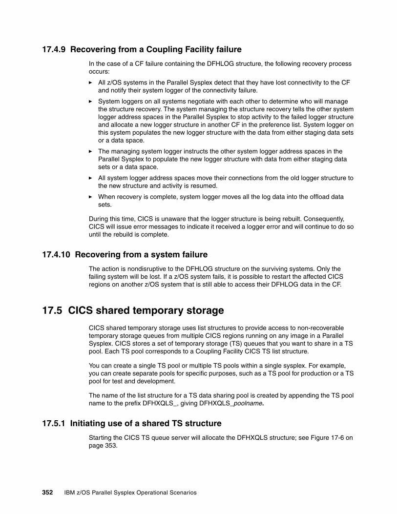
17.4.9 Recovering from a Coupling Facility failure
In the case of a CF failure containing the DFHLOG structure, the following recovery process occurs:
� All z/OS systems in the Parallel Sysplex detect that they have lost connectivity to the CF and notify their system logger of the connectivity failure.
� System loggers on all systems negotiate with each other to determine who will manage the structure recovery. The system managing the structure recovery tells the other system logger address spaces in the Parallel Sysplex to stop activity to the failed logger structure and allocate a new logger structure in another CF in the preference list. System logger on this system populates the new logger structure with the data from either staging data sets or a data space.
� The managing system logger instructs the other system logger address spaces in the Parallel Sysplex to populate the new logger structure with data from either staging data sets or a data space.
� All system logger address spaces move their connections from the old logger structure to the new structure and activity is resumed.
� When recovery is complete, system logger moves all the log data into the offload data sets.
During this time, CICS is unaware that the logger structure is being rebuilt. Consequently, CICS will issue error messages to indicate it received a logger error and will continue to do so until the rebuild is complete.
17.4.10 Recovering from a system failure
The action is nondisruptive to the DFHLOG structure on the surviving systems. Only the failing system will be lost. If a z/OS system fails, it is possible to restart the affected CICS regions on another z/OS system that is still able to access their DFHLOG data in the CF.
17.5 CICS shared temporary storage
CICS shared temporary storage uses list structures to provide access to non-recoverable temporary storage queues from multiple CICS regions running on any image in a Parallel Sysplex. CICS stores a set of temporary storage (TS) queues that you want to share in a TS pool. Each TS pool corresponds to a Coupling Facility CICS TS list structure.
You can create a single TS pool or multiple TS pools within a single sysplex. For example, you can create separate pools for specific purposes, such as a TS pool for production or a TS pool for test and development.
The name of the list structure for a TS data sharing pool is created by appending the TS pool name to the prefix DFHXQLS_, giving DFHXQLS_poolname.
17.5.1 Initiating use of a shared TS structure
Starting the CICS TS queue server will allocate the DFHXQLS structure; see Figure 17-6 on page 353.
352 IBM z/OS Parallel Sysplex Operational Scenarios
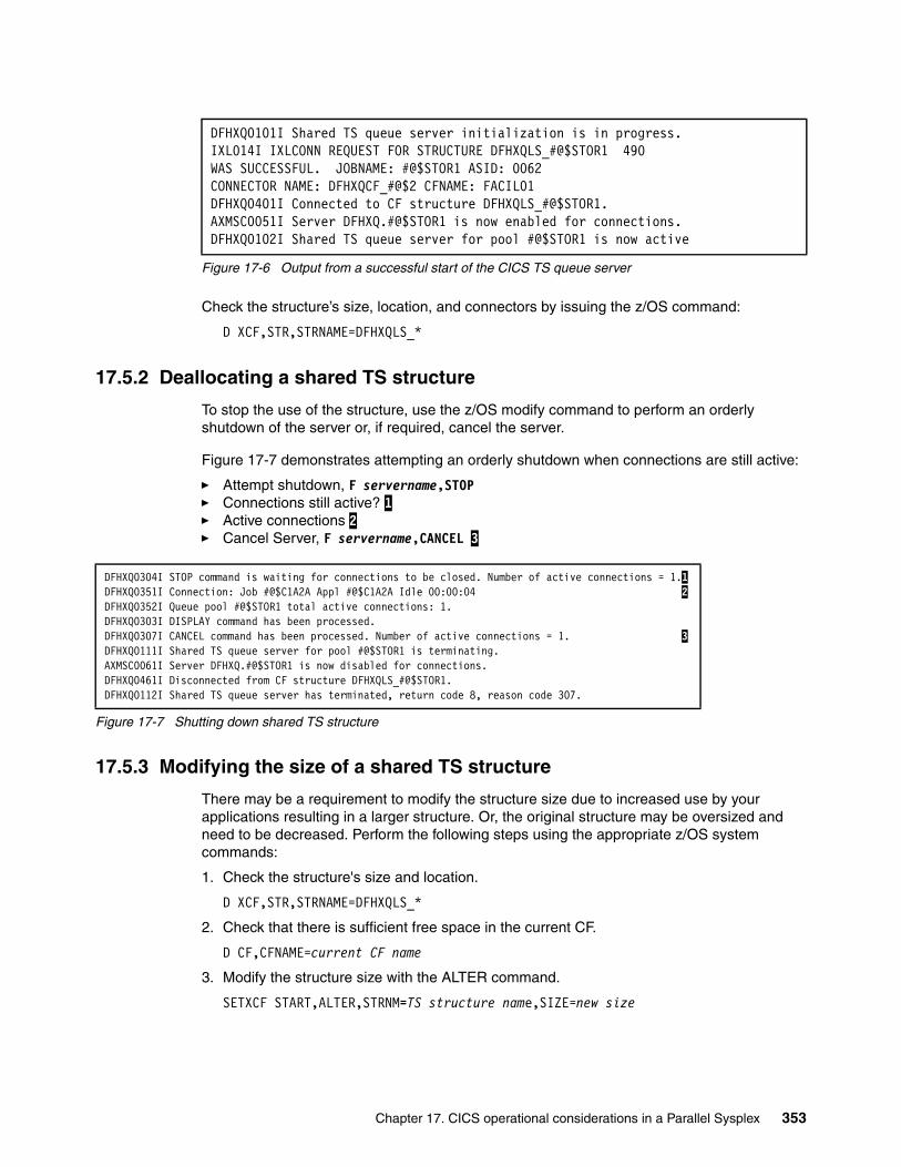
Figure 17-6 Output from a successful start of the CICS TS queue server
Check the structure’s size, location, and connectors by issuing the z/OS command:
D XCF,STR,STRNAME=DFHXQLS_*
17.5.2 Deallocating a shared TS structure
To stop the use of the structure, use the z/OS modify command to perform an orderly shutdown of the server or, if required, cancel the server.
Figure 17-7 demonstrates attempting an orderly shutdown when connections are still active:
� Attempt shutdown, F servername,STOP� Connections still active? 1 � Active connections 2 � Cancel Server, F servername,CANCEL 3
Figure 17-7 Shutting down shared TS structure
17.5.3 Modifying the size of a shared TS structure
There may be a requirement to modify the structure size due to increased use by your applications resulting in a larger structure. Or, the original structure may be oversized and need to be decreased. Perform the following steps using the appropriate z/OS system commands:
1. Check the structure's size and location.
D XCF,STR,STRNAME=DFHXQLS_*
2. Check that there is sufficient free space in the current CF.
D CF,CFNAME=current CF name
3. Modify the structure size with the ALTER command.
SETXCF START,ALTER,STRNM=TS structure name,SIZE=new size
DFHXQ0101I Shared TS queue server initialization is in progress. IXL014I IXLCONN REQUEST FOR STRUCTURE DFHXQLS_#@$STOR1 490 WAS SUCCESSFUL. JOBNAME: #@$STOR1 ASID: 0062 CONNECTOR NAME: DFHXQCF_#@$2 CFNAME: FACIL01 DFHXQ0401I Connected to CF structure DFHXQLS_#@$STOR1. AXMSC0051I Server DFHXQ.#@$STOR1 is now enabled for connections. DFHXQ0102I Shared TS queue server for pool #@$STOR1 is now active
DFHXQ0304I STOP command is waiting for connections to be closed. Number of active connections = 1.1DFHXQ0351I Connection: Job #@$C1A2A Appl #@$C1A2A Idle 00:00:04 2DFHXQ0352I Queue pool #@$STOR1 total active connections: 1. DFHXQ0303I DISPLAY command has been processed. DFHXQ0307I CANCEL command has been processed. Number of active connections = 1. 3DFHXQ0111I Shared TS queue server for pool #@$STOR1 is terminating. AXMSC0061I Server DFHXQ.#@$STOR1 is now disabled for connections. DFHXQ0461I Disconnected from CF structure DFHXQLS_#@$STOR1. DFHXQ0112I Shared TS queue server has terminated, return code 8, reason code 307.
Chapter 17. CICS operational considerations in a Parallel Sysplex 353
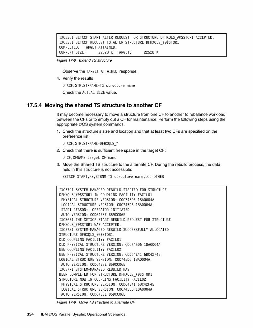
Figure 17-8 Extend TS structure
Observe the TARGET ATTAINED response.
4. Verify the results
D XCF,STR,STRNAME=TS structure name
Check the ACTUAL SIZE value.
17.5.4 Moving the shared TS structure to another CF
It may become necessary to move a structure from one CF to another to rebalance workload between the CFs or to empty out a CF for maintenance. Perform the following steps using the appropriate z/OS system commands.
1. Check the structure's size and location and that at least two CFs are specified on the preference list:
D XCF,STR,STRNAME=DFHXQLS_*
2. Check that there is sufficient free space in the target CF:
D CF,CFNAME=target CF name
3. Move the Shared TS structure to the alternate CF. During the rebuild process, the data held in this structure is not accessible:
SETXCF START,RB,STRNM=TS structure name,LOC=OTHER
Figure 17-9 Move TS structure to alternate CF
IXC530I SETXCF START ALTER REQUEST FOR STRUCTURE DFHXQLS_#@$STOR1 ACCEPTED. IXC533I SETXCF REQUEST TO ALTER STRUCTURE DFHXQLS_#@$STOR1 COMPLETED. TARGET ATTAINED. CURRENT SIZE: 22528 K TARGET: 22528 K
IXC570I SYSTEM-MANAGED REBUILD STARTED FOR STRUCTURE DFHXQLS_#@$STOR1 IN COUPLING FACILITY FACIL01 PHYSICAL STRUCTURE VERSION: C0C745D6 18A0004A LOGICAL STRUCTURE VERSION: C0C745D6 18A0004A START REASON: OPERATOR-INITIATED AUTO VERSION: C0D64E3E B59CC06E IXC367I THE SETXCF START REBUILD REQUEST FOR STRUCTUREDFHXQLS_#@$STOR1 WAS ACCEPTED. IXC578I SYSTEM-MANAGED REBUILD SUCCESSFULLY ALLOCATED STRUCTURE DFHXQLS_#@$STOR1. OLD COUPLING FACILITY: FACIL01 OLD PHYSICAL STRUCTURE VERSION: C0C745D6 18A0004A NEW COUPLING FACILITY: FACIL02 NEW PHYSICAL STRUCTURE VERSION: C0D64E41 6BC42F45 LOGICAL STRUCTURE VERSION: C0C745D6 18A0004A AUTO VERSION: C0D64E3E B59CC06E IXC577I SYSTEM-MANAGED REBUILD HAS BEEN COMPLETED FOR STRUCTURE DFHXQLS_#@$STOR1 STRUCTURE NOW IN COUPLING FACILITY FACIL02 PHYSICAL STRUCTURE VERSION: C0D64E41 6BC42F45 LOGICAL STRUCTURE VERSION: C0C745D6 18A0004A AUTO VERSION: C0D64E3E B59CC06E
354 IBM z/OS Parallel Sysplex Operational Scenarios

4. Verify the results
D XCF,STR,STRNAME=TS structure name
a. Check that CFNAME is pointing to the desired target CF.
b. It should still be connected to the same address spaces that it was before the Rebuild was issued. Check the details under CONNECTION NAME.
17.5.5 Recovery from a CF failure
In the event of a CF failure where there is no connectivity to the Shared TS Queue structure, the server will terminate automatically, as displayed in Figure 17-10. The server may be restarted, where it will attempt to connect to the original structure. If this should fail, it will allocate a new structure in an alternate CF.
Figure 17-10 Loss of CF connectivity with no duplexing of the structure
If System-Managed Duplexing were used, recovery would have been seamless. See 7.4, “Structure duplexing” on page 112 for more details about that topic.
17.5.6 Recovery from a system failure
The action is nondisruptive to the shared TS structure on the surviving systems. Only the failing system will be lost.
17.6 CICS CF data tables
Coupling Facility data tables (CFDT) provide a method of file data sharing without the need for a file-owning region and without the need for VSAM RLS support. CICS Coupling Facility data table support is designed to provide rapid sharing of working data across a sysplex, with update integrity. Read/write access to CFDTs have similar performance, thus making this form of table particularly useful for informal shared data. Informal shared data is characterized as:
� Data that is relatively short term in nature, which is either created as the application is running, or is initially loaded from an external source
� Data volumes that are not usually very large
� Data that needs to be accessed fast
� Data that commonly requires update integrity
DFHXQ0424 Connectivity has been lost to CF structure 441 DFHXQLS_#@$STOR1. The shared TS queue server cannot continue. DFHXQ0307I CANCEL RESTART=YES command has been processed. Number ofactive connections = 0. DFHXQ0111I Shared TS queue server for pool #@$STOR1 is terminating.AXMSC0061I Server DFHXQ.#@$STOR1 is now disabled for connections.
Chapter 17. CICS operational considerations in a Parallel Sysplex 355
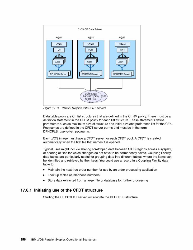
Figure 17-11 Parallel Sysplex with CFDT servers
Data table pools are CF list structures that are defined in the CFRM policy. There must be a definition statement in the CFRM policy for each list structure. These statements define parameters such as maximum size of structure and initial size and preference list for the CFs. Poolnames are defined in the CFDT server parms and must be in the form DFHCFLS_user-given poolname.
Each z/OS image must have a CFDT server for each CFDT pool. A CFDT is created automatically when the first file that names it is opened.
Typical uses might include sharing scratchpad data between CICS regions across a sysplex, or sharing of files for which changes do not have to be permanently saved. Coupling Facility data tables are particularly useful for grouping data into different tables, where the items can be identified and retrieved by their keys. You could use a record in a Coupling Facility data table to:
� Maintain the next free order number for use by an order processing application
� Look up tables of telephone numbers
� Store data extracted from a larger file or database for further processing
17.6.1 Initiating use of the CFDT structure
Starting the CICS CFDT server will allocate the DFHCFLS structure.
356 IBM z/OS Parallel Sysplex Operational Scenarios
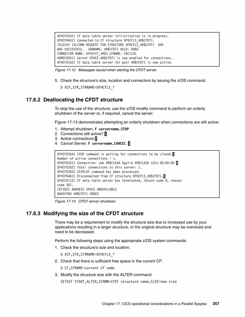
Figure 17-12 Messages issued when starting the CFDT server
5. Check the structure’s size, location and connectors by issuing the z/OS command:
D XCF,STR,STRNAME=DFHCFLS_*
17.6.2 Deallocating the CFDT structure
To stop the use of the structure, use the z/OS modify command to perform an orderly shutdown of the server or, if required, cancel the server.
Figure 17-13 demonstrates attempting an orderly shutdown when connections are still active:
1. Attempt shutdown, F servername,STOP2. Connections still active? 13. Active connections 24. Cancel Server, F servername,CANCEL 3.
Figure 17-13 CFDT server shutdown
17.6.3 Modifying the size of the CFDT structure
There may be a requirement to modify the structure size due to increased use by your applications resulting in a larger structure, or the original structure may be oversized and need to be decreased.
Perform the following steps using the appropriate z/OS system commands.
1. Check the structure's size and location:
D XCF,STR,STRNAME=DFHCFLS_*
2. Check that there is sufficient free space in the current CF:
D CF,CFNAME=current CF name
3. Modify the structure size with the ALTER command:
SETXCF START,ALTER,STRNM=CFDT structure name,SIZE=new size
DFHCF0101I CF data table server initialization is in progress. DFHCF0401I Connected to CF structure DFHCFLS_#@$CFDT1. IXL014I IXLCONN REQUEST FOR STRUCTURE DFHCFLS_#@$CFDT1 095 WAS SUCCESSFUL. JOBNAME: #@$CFDT1 ASID: 0060 CONNECTOR NAME: DFHCFCF_#@$3 CFNAME: FACIL01 AXMSC0051I Server DFHCF.#@$CFDT1 is now enabled for connections. DFHCF0102I CF data table server for pool #@$CFDT1 is now active.
DFHCF0304I STOP command is waiting for connections to be closed.1Number of active connections = 1. DFHCF0351I Connection: Job #@$C1A3A Applid #@$C1A3A Idle 00:00:00 2DFHCF0352I Total connections to this server: 1. DFHCF0303I DISPLAY command has been processed. DFHCF0461I Disconnected from CF structure DFHCFLS_#@$CFDT1.3DFHCF0112I CF data table server has terminated, return code 8, reasoncode 307.IEF352I ADDRESS SPACE UNAVAILABLE$HASP395 #@$CFDT1 ENDED
Chapter 17. CICS operational considerations in a Parallel Sysplex 357

Figure 17-14 Extend CFDT structure
Observe the TARGET ATTAINED response.
4. Verify the results.
D XCF,STR,STRNAME=CFDT structure name
Check the ACTUAL SIZE value.
17.6.4 Moving the CFDT structure to another CF
It may become necessary to move a structure from one CF to another, to rebalance workload between the CFs or to empty out a CF for maintenance. Perform the following steps using the appropriate z/OS system commands.
1. Check the structure's size and location and that at least two CFs are specified on the preference list:
D XCF,STR,STRNAME=DFHCFLS_*
2. Check that there is sufficient free space in the target CF:
D CF,CFNAME=target CF name
3. Move the CFDT structure to the alternate CF. During the rebuild process the data held in this structure is not accessible:
SETXCF START,RB,STRNM=CFDT structure name,LOC=OTHER
Figure 17-15 Partial output from the CFDT structure rebuild process
4. Verify the results.
D XCF,STR,STRNAME=CFDT structure name
a. Check that CFNAME is pointing to the desired target CF.
b. It should still be connected to the same address spaces that it was before the Rebuild was issued. Check the details under CONNECTION NAME.
17.6.5 Recovering CFDT after CF failure
In the event of a CF failure where there is no connectivity to the CFDT structure, the server will terminate automatically as displayed in Figure 17-16 on page 359. The server may be
IXC530I SETXCF START ALTER REQUEST FOR STRUCTURE DFHCFLS_#@$CFDT1 ACCEPTED.IXC533I SETXCF REQUEST TO ALTER STRUCTURE DFHCFLS_#@$CFDT1 COMPLETED. TARGET ATTAINED. CURRENT SIZE: 6144 K TARGET: 6144 K
IXC578I SYSTEM-MANAGED REBUILD SUCCESSFULLY ALLOCATED STRUCTURE DFHCFLS_#@$CFDT1. OLD COUPLING FACILITY: FACIL01 OLD PHYSICAL STRUCTURE VERSION: C0C745DA B7AD3A4E NEW COUPLING FACILITY: FACIL02 IXC577I SYSTEM-MANAGED REBUILD HAS BEEN COMPLETED FOR STRUCTURE DFHCFLS_#@$CFDT1STRUCTURE NOW IN COUPLING FACILITY FACIL02
358 IBM z/OS Parallel Sysplex Operational Scenarios
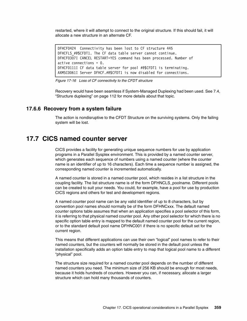
restarted, where it will attempt to connect to the original structure. If this should fail, it will allocate a new structure in an alternate CF.
Figure 17-16 Loss of CF connectivity to the CFDT structure
Recovery would have been seamless if System-Managed Duplexing had been used. See 7.4, “Structure duplexing” on page 112 for more details about that topic.
17.6.6 Recovery from a system failure
The action is nondisruptive to the CFDT Structure on the surviving systems. Only the failing system will be lost.
17.7 CICS named counter server
CICS provides a facility for generating unique sequence numbers for use by application programs in a Parallel Sysplex environment. This is provided by a named counter server, which generates each sequence of numbers using a named counter (where the counter name is an identifier of up to 16 characters). Each time a sequence number is assigned, the corresponding named counter is incremented automatically.
A named counter is stored in a named counter pool, which resides in a list structure in the coupling facility. The list structure name is of the form DFHNCLS_poolname. Different pools can be created to suit your needs. You could, for example, have a pool for use by production CICS regions and others for test and development regions.
A named counter pool name can be any valid identifier of up to 8 characters, but by convention pool names should normally be of the form DFHNCxxx. The default named counter options table assumes that when an application specifies a pool selector of this form, it is referring to that physical named counter pool. Any other pool selector for which there is no specific option table entry is mapped to the default named counter pool for the current region, or to the standard default pool name DFHNC001 if there is no specific default set for the current region.
This means that different applications can use their own “logical” pool names to refer to their named counters, but the counters will normally be stored in the default pool unless the installation specifically adds an option table entry to map that logical pool name to a different “physical” pool.
The structure size required for a named counter pool depends on the number of different named counters you need. The minimum size of 256 KB should be enough for most needs, because it holds hundreds of counters. However you can, if necessary, allocate a larger structure which can hold many thousands of counters.
DFHCF0424 Connectivity has been lost to CF structure 445 DFHCFLS_#@$CFDT1. The CF data table server cannot continue. DFHCF0307I CANCEL RESTART=YES command has been processed. Number ofactive connections = 0. DFHCF0111I CF data table server for pool #@$CFDT1 is terminating. AXMSC0061I Server DFHCF.#@$CFDT1 is now disabled for connections.
Chapter 17. CICS operational considerations in a Parallel Sysplex 359
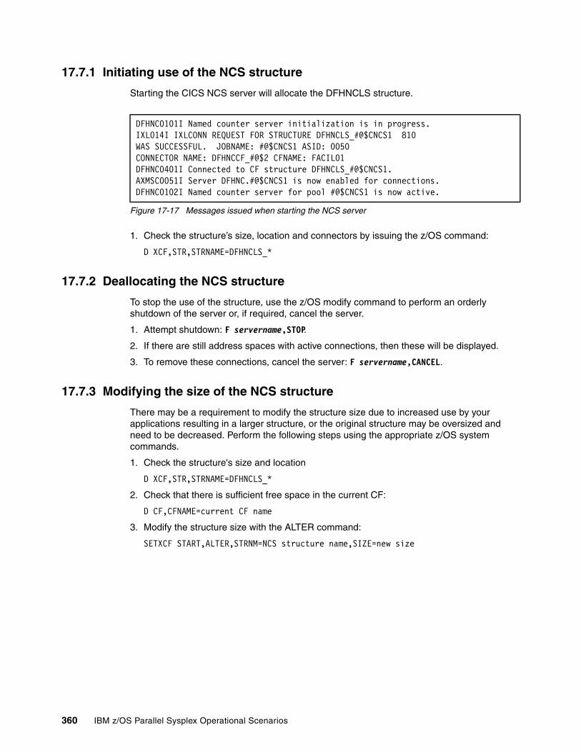
17.7.1 Initiating use of the NCS structure
Starting the CICS NCS server will allocate the DFHNCLS structure.
Figure 17-17 Messages issued when starting the NCS server
1. Check the structure’s size, location and connectors by issuing the z/OS command:
D XCF,STR,STRNAME=DFHNCLS_*
17.7.2 Deallocating the NCS structure
To stop the use of the structure, use the z/OS modify command to perform an orderly shutdown of the server or, if required, cancel the server.
1. Attempt shutdown: F servername,STOP.
2. If there are still address spaces with active connections, then these will be displayed.
3. To remove these connections, cancel the server: F servername,CANCEL.
17.7.3 Modifying the size of the NCS structure
There may be a requirement to modify the structure size due to increased use by your applications resulting in a larger structure, or the original structure may be oversized and need to be decreased. Perform the following steps using the appropriate z/OS system commands.
1. Check the structure's size and location
D XCF,STR,STRNAME=DFHNCLS_*
2. Check that there is sufficient free space in the current CF:
D CF,CFNAME=current CF name
3. Modify the structure size with the ALTER command:
SETXCF START,ALTER,STRNM=NCS structure name,SIZE=new size
DFHNC0101I Named counter server initialization is in progress. IXL014I IXLCONN REQUEST FOR STRUCTURE DFHNCLS_#@$CNCS1 810 WAS SUCCESSFUL. JOBNAME: #@$CNCS1 ASID: 0050 CONNECTOR NAME: DFHNCCF_#@$2 CFNAME: FACIL01 DFHNC0401I Connected to CF structure DFHNCLS_#@$CNCS1. AXMSC0051I Server DFHNC.#@$CNCS1 is now enabled for connections. DFHNC0102I Named counter server for pool #@$CNCS1 is now active.
360 IBM z/OS Parallel Sysplex Operational Scenarios
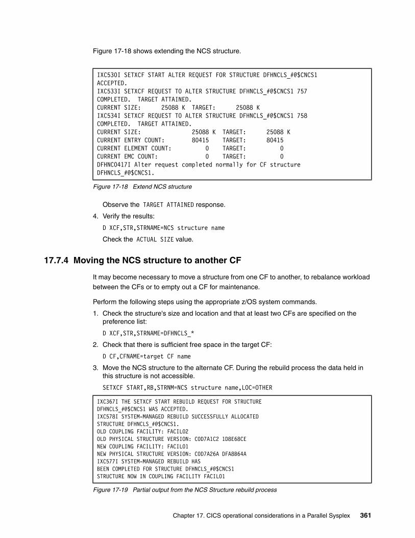
Figure 17-18 shows extending the NCS structure.
Figure 17-18 Extend NCS structure
Observe the TARGET ATTAINED response.
4. Verify the results:
D XCF,STR,STRNAME=NCS structure name
Check the ACTUAL SIZE value.
17.7.4 Moving the NCS structure to another CF
It may become necessary to move a structure from one CF to another, to rebalance workload
between the CFs or to empty out a CF for maintenance.
Perform the following steps using the appropriate z/OS system commands.
1. Check the structure's size and location and that at least two CFs are specified on the preference list:
D XCF,STR,STRNAME=DFHNCLS_*
2. Check that there is sufficient free space in the target CF:
D CF,CFNAME=target CF name
3. Move the NCS structure to the alternate CF. During the rebuild process the data held in this structure is not accessible.
SETXCF START,RB,STRNM=NCS structure name,LOC=OTHER
Figure 17-19 Partial output from the NCS Structure rebuild process
IXC530I SETXCF START ALTER REQUEST FOR STRUCTURE DFHNCLS_#@$CNCS1ACCEPTED. IXC533I SETXCF REQUEST TO ALTER STRUCTURE DFHNCLS_#@$CNCS1 757 COMPLETED. TARGET ATTAINED. CURRENT SIZE: 25088 K TARGET: 25088 K IXC534I SETXCF REQUEST TO ALTER STRUCTURE DFHNCLS_#@$CNCS1 758 COMPLETED. TARGET ATTAINED. CURRENT SIZE: 25088 K TARGET: 25088 K CURRENT ENTRY COUNT: 80415 TARGET: 80415 CURRENT ELEMENT COUNT: 0 TARGET: 0 CURRENT EMC COUNT: 0 TARGET: 0 DFHNC0417I Alter request completed normally for CF structure DFHNCLS_#@$CNCS1.
IXC367I THE SETXCF START REBUILD REQUEST FOR STRUCTUREDFHNCLS_#@$CNCS1 WAS ACCEPTED. IXC578I SYSTEM-MANAGED REBUILD SUCCESSFULLY ALLOCATED STRUCTURE DFHNCLS_#@$CNCS1. OLD COUPLING FACILITY: FACIL02 OLD PHYSICAL STRUCTURE VERSION: C0D7A1C2 1D8E68CE NEW COUPLING FACILITY: FACIL01 NEW PHYSICAL STRUCTURE VERSION: C0D7A26A DFA8B64A IXC577I SYSTEM-MANAGED REBUILD HAS BEEN COMPLETED FOR STRUCTURE DFHNCLS_#@$CNCS1 STRUCTURE NOW IN COUPLING FACILITY FACIL01
Chapter 17. CICS operational considerations in a Parallel Sysplex 361
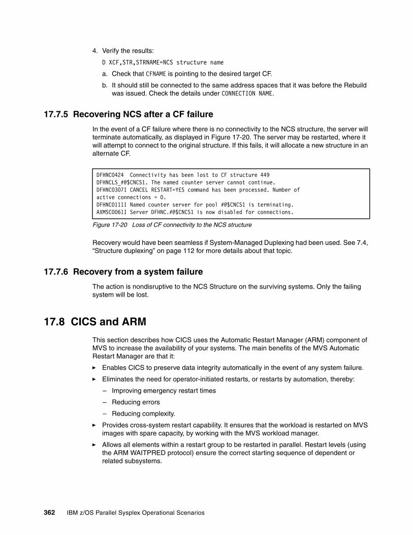
4. Verify the results:
D XCF,STR,STRNAME=NCS structure name
a. Check that CFNAME is pointing to the desired target CF.
b. It should still be connected to the same address spaces that it was before the Rebuild was issued. Check the details under CONNECTION NAME.
17.7.5 Recovering NCS after a CF failure
In the event of a CF failure where there is no connectivity to the NCS structure, the server will terminate automatically, as displayed in Figure 17-20. The server may be restarted, where it will attempt to connect to the original structure. If this fails, it will allocate a new structure in an alternate CF.
Figure 17-20 Loss of CF connectivity to the NCS structure
Recovery would have been seamless if System-Managed Duplexing had been used. See 7.4, “Structure duplexing” on page 112 for more details about that topic.
17.7.6 Recovery from a system failure
The action is nondisruptive to the NCS Structure on the surviving systems. Only the failing system will be lost.
17.8 CICS and ARM
This section describes how CICS uses the Automatic Restart Manager (ARM) component of MVS to increase the availability of your systems. The main benefits of the MVS Automatic Restart Manager are that it:
� Enables CICS to preserve data integrity automatically in the event of any system failure.
� Eliminates the need for operator-initiated restarts, or restarts by automation, thereby:
– Improving emergency restart times
– Reducing errors
– Reducing complexity.
� Provides cross-system restart capability. It ensures that the workload is restarted on MVS images with spare capacity, by working with the MVS workload manager.
� Allows all elements within a restart group to be restarted in parallel. Restart levels (using the ARM WAITPRED protocol) ensure the correct starting sequence of dependent or related subsystems.
DFHNC0424 Connectivity has been lost to CF structure 449 DFHNCLS_#@$CNCS1. The named counter server cannot continue. DFHNC0307I CANCEL RESTART=YES command has been processed. Number of active connections = 0. DFHNC0111I Named counter server for pool #@$CNCS1 is terminating. AXMSC0061I Server DFHNC.#@$CNCS1 is now disabled for connections.
362 IBM z/OS Parallel Sysplex Operational Scenarios
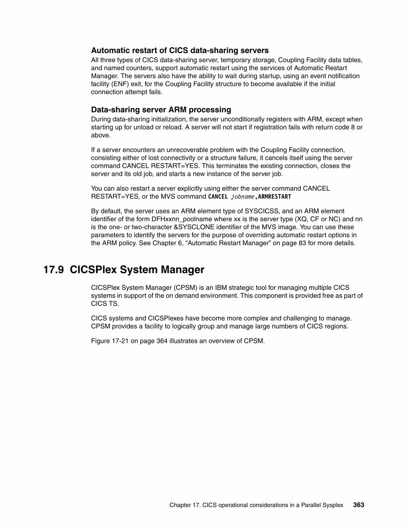
Automatic restart of CICS data-sharing serversAll three types of CICS data-sharing server, temporary storage, Coupling Facility data tables, and named counters, support automatic restart using the services of Automatic Restart Manager. The servers also have the ability to wait during startup, using an event notification facility (ENF) exit, for the Coupling Facility structure to become available if the initial connection attempt fails.
Data-sharing server ARM processingDuring data-sharing initialization, the server unconditionally registers with ARM, except when starting up for unload or reload. A server will not start if registration fails with return code 8 or above.
If a server encounters an unrecoverable problem with the Coupling Facility connection, consisting either of lost connectivity or a structure failure, it cancels itself using the server command CANCEL RESTART=YES. This terminates the existing connection, closes the server and its old job, and starts a new instance of the server job.
You can also restart a server explicitly using either the server command CANCEL RESTART=YES, or the MVS command CANCEL jobname,ARMRESTART
By default, the server uses an ARM element type of SYSCICSS, and an ARM element identifier of the form DFHxxnn_poolname where xx is the server type (XQ, CF or NC) and nn is the one- or two-character &SYSCLONE identifier of the MVS image. You can use these parameters to identify the servers for the purpose of overriding automatic restart options in the ARM policy. See Chapter 6, “Automatic Restart Manager” on page 83 for more details.
17.9 CICSPlex System Manager
CICSPlex System Manager (CPSM) is an IBM strategic tool for managing multiple CICS systems in support of the on demand environment. This component is provided free as part of CICS TS.
CICS systems and CICSPlexes have become more complex and challenging to manage. CPSM provides a facility to logically group and manage large numbers of CICS regions.
Figure 17-21 on page 364 illustrates an overview of CPSM.
Chapter 17. CICS operational considerations in a Parallel Sysplex 363

Figure 17-21 CPSM overview
17.10 What is CICSPlex
A CICSPlex is commonly described as a set of interconnected CICS regions that process customer workload. A typical CICSPlex is the set of interconnected TORs, AORs, FORs, and so on. For CICSPlex SM purposes, a CICSPlex is any logical grouping of CICS regions that you want to manage and manipulate as a whole. CICSPlexes are typically groups of systems that are logically related by usage, for example, test, quality assurance, or production CICSPlexes.
A CICSPlex managed by CICSPlex SM has the following attributes:
� The CICSPlex is the largest unit you can work with. That is, you cannot group CICSPlexes and manipulate such a group as a single entity.
� CICSPlexes are mutually exclusive, so no CICS region can belong to more than one CICSPlex.
� CPSM enables you to define subsets of a CICSPlex, which are known as system groups. CICS system groups are not mutually exclusive, and can reference the same CICS regions, or other system groups. CICS system groups are typically used to represent region types such as the set of TORs or AORs, a physical location such as the CICS regions on a z/OS image, or a set of CICS regions processing a workload.
364 IBM z/OS Parallel Sysplex Operational Scenarios
17.10.1 CPSM components
CPSM consists of the following components.
CICSPlex System Manager CICSPlex System Manager (CMAS) a CICS region dedicated solely to the CICSPlex SM function responsible for managing and reporting on all CICS regions and resources within the defined CICSPlex or CICSPlexes. The CMAS interacts with CICSPlex SM agent code running on each managed CICS region (MAS) to define events or conditions of interest, and collect information. A CMAS region is not part of a managed CICSPlex.
Coordinating Address Space Coordinating Address Space (CAS) is used to set up the CICSPlex SM component topology, and to support the MVS/TSO ISPF end-user interface (EUI) to CPSM.
Web User Interface The Web User Interface (WUI) offers an easy-to-use interface that you can use to carry out operational and administrative tasks necessary to monitor and control CICS resources. CPSM allows you, via the Web browser interface, to manipulate CICS regions with a single command.
ISPF interfaceAn ISPF interface is available to carry out operational and administrative tasks.
Environment Services System ServicesEnvironment Services System Services (ESSS) is an address space that is started automatically upon startup of the CMAS. It provides MVS system services to the CPSM components.
Real Time AnalysisReal Time Analysis (RTA) provides system-wide monitoring and problem resolution. Performance thresholds can be set on all aspects of the system critical to maintaining performance and throughput.
RTA provides a System Availability Monitor (SAM), which monitors the health of all systems within the CICSPlex. If a threshold is exceeded anywhere within the CICSPlex, it triggers an event pinpointing the system and threshold instantly. You are alerted and are able to use CPSM to diagnose and repair the problem from a single point of control. There is also a provision to configure automatic recovery from specific error conditions. For example if a DB2 connection is lost RTA reports this and CPSM can take remedial action to restore the connection without user intervention.
Business Application ServicesBusiness Application Services (BAS) allows you to replicate entire applications and their resources from a single point of control. BAS is similar to CICS Resource Definition Online (RDO) with some differences:
� A resource can belong to more than one group.
� It allows the creation of resource definitions for all supported releases of CICS.
� It provides Logical Scoping, which means that resources can be grouped according to the application they are used in.
� SYSLINK construct simplifies connection installation.
Chapter 17. CICS operational considerations in a Parallel Sysplex 365
Workload ManagerThe Workload Manager (WLM) component of CPSM provides for dynamic workload balancing. WLM routes transactions to regions based upon predefined performance criteria. If one region reaches a performance threshold, either through volume of work or because of some problem, WLM stops routing work to it until the workload has reduced. WLM, therefore, ensures optimum capacity usage and throughput, and guards against any system in its cluster becoming a single point of failure.
Note that with WLM, work is not balanced in a round-robin fashion. WLM selects the system most likely to meet specified criteria by using either the QUEUE algorithm or GOAL algorithm.
QUEUE algorithmThe QUEUE algorithm uses the following selection criteria:
� Selects the system with shortest queue of work relative to system MAXTASKS
� The system least likely to be affected by Short on Storage, SYSDUMP, and TRANDUMP conditions
� The system least likely to cause the transaction to abend
� Standardizes response times across a CICSPlex
� Accommodates differences in processor power and MAXTASK values, asymmetric region configuration and unpredictable workloads.
GOAL algorithmThe GOAL algorithm uses the following selection criteria:
� Selects system least likely to be affected by SOS, SYSDUMP, and TRANDUMP conditions
� The system least likely to cause the transaction to abend
� Most likely to meet average MVS WLM response time goals
17.10.2 Coupling Facility structures for CPSM
CPSM does not currently use any Coupling Facility structures.
366 IBM z/OS Parallel Sysplex Operational Scenarios
Chapter 18. DB2 operational considerations in a Parallel Sysplex
This chapter introduces DB2 Data Sharing and provides an overview of operational considerations when it is implemented in a Parallel Sysplex.
18
© Copyright IBM Corp. 2009. All rights reserved. 367
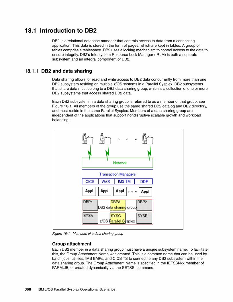
18.1 Introduction to DB2
DB2 is a relational database manager that controls access to data from a connecting application. This data is stored in the form of pages, which are kept in tables. A group of tables comprise a tablespace. DB2 uses a locking mechanism to control access to the data to ensure integrity. DB2's Intersystem Resource Lock Manager (IRLM) is both a separate subsystem and an integral component of DB2.
18.1.1 DB2 and data sharing
Data sharing allows for read and write access to DB2 data concurrently from more than one DB2 subsystem residing on multiple z/OS systems in a Parallel Sysplex. DB2 subsystems that share data must belong to a DB2 data sharing group, which is a collection of one or more DB2 subsystems that access shared DB2 data.
Each DB2 subsystem in a data sharing group is referred to as a member of that group; see Figure 18-1. All members of the group use the same shared DB2 catalog and DB2 directory, and must reside in the same Parallel Sysplex. Members of a data sharing group are independent of the applications that support nondisruptive scalable growth and workload balancing.
Figure 18-1 Members of a data sharing group
Group attachmentEach DB2 member in a data sharing group must have a unique subsystem name. To facilitate this, the Group Attachment Name was created. This is a common name that can be used by batch jobs, utilities, IMS BMPs, and CICS TS to connect to any DB2 subsystem within the data sharing group. The Group Attachment Name is specified in the IEFSSNxx member of PARMLIB, or created dynamically via the SETSSI command.
368 IBM z/OS Parallel Sysplex Operational Scenarios
18.2 DB2 structure concepts
Members of the DB2 data sharing group use areas of storage in the CF called structures to communicate and move data among the members. There are three types of structures:
� Lock� List� Cache
Lock structureThere is one lock structure per data sharing group. This is used by IRLM to serialize the resources used by the associated data sharing group. The naming convention for the lock structure is DB2-data-sharing-groupname_LOCK1.
List structureThere is one list structure per data sharing group used as a Shared Communication Area (SCA) for the members of the group. The SCA contains all database exception status conditions, copies of the Boot Strap Data Sets (BSDS), and other information. The naming convention for the SCA structure is DB2-data-sharing-groupname_SCA.
Cache structureGroup Buffer Pools (GBPs) are used to cache data in the CF and to maintain the consistency of data across the buffer pools of members of the group by using a cross-invalidating mechanism. Cross Invalidation is used to notify a member when its local buffer pool contains an out-of-date copy of the data. The next time the DB2 member tries to use that data, it must get the current data from either the GBP or DASD.
One GBP is used for all local buffer pools of the same name in the DB2 group that contain shared data. For example, each DB2 must have a local buffer pool named BP0 to contain the catalog and directory table spaces. Therefore, you must define a GBP0 in a CF that maps to local buffer pool BP0.
How GBP worksThe solution that is implemented in a Parallel Sysplex is for each database manager to tell the Coupling Facility (CF) every time it adds a record to its local buffer. The CF then knows which instances have a copy of any given piece of data. Each instance also tells the CF every time it updates one of those records. The CF knows who has a copy of each record, and it also knows who it has to tell when a given record is updated. This is the process of Cross Invalidation, and it is handled automatically by the database managers and the CF.
18.3 GBP structure management and recovery
If only one member of the DB2 data sharing group is started, then no GBP structures will be allocated because no other DB2 is using any of the databases. As soon as another member of the DB2 data sharing group is started and any database is being updated, the GBP0 structure will immediately be allocated. A CF for the Lock and DB2 SCA structures is still required, even when all members of the data sharing group have been stopped.
In general, if a DB2 member in a data sharing group terminates normally, the connection to the GBP is deleted. When all the DB2 members in the data sharing group terminate in a normal fashion, then all connections to the GBP will be deleted and the GBP structure is deallocated. The structure is deallocated because its structure disposition is DELETE. A
Chapter 18. DB2 operational considerations in a Parallel Sysplex 369
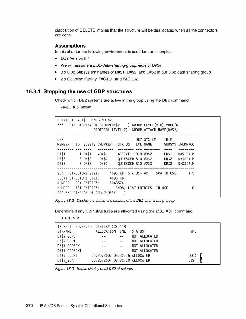
disposition of DELETE implies that the structure will be deallocated when all the connectors are gone.
AssumptionsIn this chapter the following environment is used for our examples:
� DB2 Version 8.1
� We will assume a DB2-data-sharing-groupname of D#$#
� 3 x DB2 Subsystem names of D#$1, D#$2, and D#$3 in our DB2 data sharing group
� 2 x Coupling Facility, FACIL01 and FACIL02
18.3.1 Stopping the use of GBP structures
Check which DB2 systems are active in the group using the DB2 command:
-D#$1 DIS GROUP
Figure 18-2 Display the status of members of the DB2 data sharing group
Determine if any GBP structures are allocated using the z/OS XCF command:
D XCF,STR
Figure 18-3 Status display of all DB2 structures
DSN7100I -D#$1 DSN7GCMD 421 *** BEGIN DISPLAY OF GROUP(D#$# ) GROUP LEVEL(810) MODE(N) PROTOCOL LEVEL(2) GROUP ATTACH NAME(D#$#) --------------------------------------------------------------------DB2 DB2 SYSTEM IRLM MEMBER ID SUBSYS CMDPREF STATUS LVL NAME SUBSYS IRLMPROC-------- --- ---- -------- -------- --- -------- ---- --------D#$1 1 D#$1 -D#$1 ACTIVE 810 #@$2 DR$1 D#$1IRLMD#$2 2 D#$2 -D#$2 QUIESCED 810 #@$2 DR$2 D#$2IRLMD#$3 3 D#$3 -D#$3 QUIESCED 810 #@$3 DR$3 D#$3IRLM--------------------------------------------------------------------SCA STRUCTURE SIZE: 4096 KB, STATUS= AC, SCA IN USE: 3 %LOCK1 STRUCTURE SIZE: 4096 KB NUMBER LOCK ENTRIES: 1048576 NUMBER LIST ENTRIES: 5408, LIST ENTRIES IN USE: 0*** END DISPLAY OF GROUP(D#$# )
IXC359I 20.35.20 DISPLAY XCF 418 STRNAME ALLOCATION TIME STATUS TYPED#$#_GBP0 -- -- NOT ALLOCATED D#$#_GBP1 -- -- NOT ALLOCATED D#$#_GBP32K -- -- NOT ALLOCATED D#$#_GBP32K1 -- -- NOT ALLOCATED D#$#_LOCK1 06/20/2007 03:32:15 ALLOCATED LOCK 1D#$#_SCA 06/20/2007 03:32:10 ALLOCATED LIST 2
370 IBM z/OS Parallel Sysplex Operational Scenarios
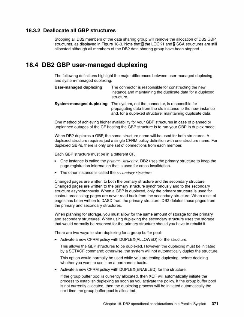
18.3.2 Deallocate all GBP structures
Stopping all DB2 members of the data sharing group will remove the allocation of DB2 GBP structures, as displayed in Figure 18-3. Note that 1 the LOCK1 and 2 SCA structures are still allocated although all members of the DB2 data sharing group have been stopped.
18.4 DB2 GBP user-managed duplexing
The following definitions highlight the major differences between user-managed duplexing and system-managed duplexing:
User-managed duplexing The connector is responsible for constructing the new instance and maintaining the duplicate data for a duplexed structure.
System-managed duplexing The system, not the connector, is responsible for propagating data from the old instance to the new instance and, for a duplexed structure, maintaining duplicate data.
One method of achieving higher availability for your GBP structures in case of planned or unplanned outages of the CF hosting the GBP structure is to run your GBP in duplex mode.
When DB2 duplexes a GBP, the same structure name will be used for both structures. A duplexed structure requires just a single CFRM policy definition with one structure name. For duplexed GBPs, there is only one set of connections from each member.
Each GBP structure must be in a different CF.
� One instance is called the primary structure. DB2 uses the primary structure to keep the page registration information that is used for cross-invalidation.
� The other instance is called the secondary structure.
Changed pages are written to both the primary structure and the secondary structure. Changed pages are written to the primary structure synchronously and to the secondary structure asynchronously. When a GBP is duplexed, only the primary structure is used for castout processing; pages are never read back from the secondary structure. When a set of pages has been written to DASD from the primary structure, DB2 deletes those pages from the primary and secondary structures.
When planning for storage, you must allow for the same amount of storage for the primary and secondary structures. When using duplexing the secondary structure uses the storage that would normally be reserved for the primary structure should you have to rebuild it.
There are two ways to start duplexing for a group buffer pool:
� Activate a new CFRM policy with DUPLEX(ALLOWED) for the structure.
This allows the GBP structures to be duplexed. However, the duplexing must be initiated by a SETXCF command; otherwise, the system will not automatically duplex the structure.
This option would normally be used while you are testing duplexing, before deciding whether you want to use it on a permanent basis.
� Activate a new CFRM policy with DUPLEX(ENABLED) for the structure.
If the group buffer pool is currently allocated, then XCF will automatically initiate the process to establish duplexing as soon as you activate the policy. If the group buffer pool is not currently allocated, then the duplexing process will be initiated automatically the next time the group buffer pool is allocated.
Chapter 18. DB2 operational considerations in a Parallel Sysplex 371
This option would normally be used when you have finished testing duplexing and have decided that you want to use it on a permanent basis.
When considering duplexing, note the following to avoid confusion:
� The primary structure is referred to as the OLD structure in many of the displays and the more recently allocated secondary structure is called the NEW structure.
� When moving a structure to another Coupling Facility or implementing a duplex structure, it is important to ensure that enough storage capacity is available to create every other structure that could be allocated in that CF. The z/OS system programmer is responsible for ensuring that there is sufficient storage capacity available in the Coupling Facility to allow every structure that needs to be allocated in a failure scenario.
� Be aware that if a structure is manually moved or duplexed, this has to be included in the calculation. Otherwise, another structure allocation may fail or a duplex recovery may fail due to CF storage not being available.
18.4.1 Preparing for user-managed duplexing
To display the status of the GBP, DB2-data-sharing-groupname_GBP1, use the following XCF command after all required DB2 subsystems have initialized:
D XCF,STR,STRNAME=D#$#_GBP1
Figure 18-4 on page 373 displays the output of the XCF view of the GBP structure.
372 IBM z/OS Parallel Sysplex Operational Scenarios

Figure 18-4 Output of the XCF view of the GBP structure
Figure 18-4 indicates:
1 Structure has a status of allocated. 2 Duplexing is permitted but can only be initiated by SETXCF START,REBUILD command. 3 The preference list includes CF FACIL01 and FACIL02. 4 Date and time the structure was allocated. 5 Currently allocated in CF FACIL02. 6 Actual size of structure, 4096 K. 7 The structure disposition is DELETE. 8 The number of connections, including DB2 subsystem information.
Before initiating duplexing, use the following command to verify that there is enough space available in the target CF to allocate the second copy of GBP:
D CF,CFNM=FACIL01
D XCF,STR,STRNM=D#$#_GBP1IXC360I 15.13.14 DISPLAY XCF 022STRNAME: D#$#_GBP1STATUS: ALLOCATED 1TYPE: CACHEPOLICY INFORMATION:POLICY SIZE : 8192 KPOLICY INITSIZE: 4096 KPOLICY MINSIZE : 0 KFULLTHRESHOLD : 80ALLOWAUTOALT : NOREBUILD PERCENT: N/ADUPLEX : ALLOWED 2ALLOWREALLOCATE: YESPREFERENCE LIST: FACIL02 FACIL01 3ENFORCEORDER : NOEXCLUSION LIST IS EMPTYACTIVE STRUCTURE----------------ALLOCATION TIME: 06/29/2007 01:07:414CFNAME : FACIL02 5COUPLING FACILITY: SIMDEV.IBM.EN.0000000CFCC2PARTITION: 00 CPCID: 00ACTUAL SIZE : 4096 K 6STORAGE INCREMENT SIZE: 512 KENTRIES: IN-USE: 18 TOTAL: 2534, 0% FULLELEMENTS: IN-USE: 18 TOTAL: 506, 3% FULLPHYSICAL VERSION: C0932A63 30E5DD94LOGICAL VERSION: C0932A63 30E5DD94SYSTEM-MANAGED PROCESS LEVEL: 14DISPOSITION : DELETE 7ACCESS TIME : 0MAX CONNECTIONS: 32# CONNECTIONS : 3 8CONNECTION NAME ID VERSION SYSNAME JOBNAME ASID STATE---------------- -- -------- -------- -------- ---- ----------DB2_D#$1 02 00020021 #@$1 D#$1DBM1 0044 ACTIVE 8DB2_D#$2 01 0001001D #@$2 D#$2DBM1 003A ACTIVEDB2_D#$3 03 00030019 #@$3 D#$3DBM1 003C ACTIVE
Chapter 18. DB2 operational considerations in a Parallel Sysplex 373
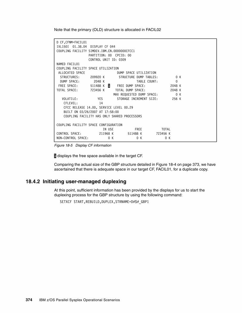
Note that the primary (OLD) structure is allocated in FACIL02
Figure 18-5 Display CF information
1 displays the free space available in the target CF.
Comparing the actual size of the GBP structure detailed in Figure 18-4 on page 373, we have ascertained that there is adequate space in our target CF, FACIL01, for a duplicate copy.
18.4.2 Initiating user-managed duplexing
At this point, sufficient information has been provided by the displays for us to start the duplexing process for the GBP structure by using the following command:
SETXCF START,REBUILD,DUPLEX,STRNAME=D#$#_GBP1
D CF,CFNM=FACIL01 IXL150I 01.38.04 DISPLAY CF 044 COUPLING FACILITY SIMDEV.IBM.EN.0000000CFCC1 PARTITION: 00 CPCID: 00 CONTROL UNIT ID: 0309 NAMED FACIL01 COUPLING FACILITY SPACE UTILIZATION ALLOCATED SPACE DUMP SPACE UTILIZATION STRUCTURES: 209920 K STRUCTURE DUMP TABLES: 0 K DUMP SPACE: 2048 K TABLE COUNT: 0 FREE SPACE: 511488 K 1 FREE DUMP SPACE: 2048 K TOTAL SPACE: 723456 K TOTAL DUMP SPACE: 2048 K MAX REQUESTED DUMP SPACE: 0 K VOLATILE: YES STORAGE INCREMENT SIZE: 256 K CFLEVEL: 14 CFCC RELEASE 14.00, SERVICE LEVEL 00.29 BUILT ON 03/26/2007 AT 17:58:00 COUPLING FACILITY HAS ONLY SHARED PROCESSORS COUPLING FACILITY SPACE CONFIGURATION IN USE FREE TOTAL CONTROL SPACE: 211968 K 511488 K 723456 K NON-CONTROL SPACE: 0 K 0 K 0 K
374 IBM z/OS Parallel Sysplex Operational Scenarios

Figure 18-6 Output from user initiated structure duplexing
From the output in Figure 18-6, note that the new structure has been allocated in 1 CF FACIL01 while the OLD structure still exists in 2 CF FACIL02. During the duplexing process, changed pages are copied from the primary to the secondary structure. The message 3 DSNB332I shows that nothing in the primary structure has been copied to the secondary structure. This could be because the duplexing process was started before the jobs got a chance to write any data into the GBP.
You may find that one of the systems will copy all the pages while the other DB2 Group members do not copy anything. This is because the castout owner is the one that is
IXC521I REBUILD FOR STRUCTURE D#$#_GBP1HAS BEEN STARTEDIXC367I THE SETXCF START REBUILD REQUEST FOR STRUCTURED#$#_GBP1 WAS ACCEPTED.DSNB740I -D#$1 DSNB1RBQ ATTEMPTING TO ESTABLISHDUPLEXING FORGROUP BUFFER POOL GBP1REASON = OPERATORDSNB740I -D#$2 DSNB1RBQ ATTEMPTING TO ESTABLISHDUPLEXING FORGROUP BUFFER POOL GBP1REASON = OPERATORIXC529I DUPLEX REBUILD NEW STRUCTURE D#$#_GBP1IS BEING ALLOCATED IN COUPLING FACILITY FACIL01 1 .OLD STRUCTURE IS ALLOCATED IN COUPLING FACILITY FACIL02 2 .REBUILD START REASON: OPERATOR INITIATED.INFO108: 00000002 00000000.DSNB302I -D#$2 DSNB1RBC GROUP BUFFER POOL GBP1-SEC ISALLOCATED IN A VOLATILE STRUCTUREIXL014I IXLCONN REBUILD REQUEST FOR STRUCTURE D#$#_GBP1WAS SUCCESSFUL. JOBNAME: D#$2DBM1 ASID: 0085CONNECTOR NAME: DB2_D#$2 CFNAME: FACIL01DSNB332I -D#$2 DSNB1PCD THIS MEMBER HAS COMPLETEDCASTOUT OWNER WORK FOR GROUP BUFFER POOL GBP1PAGES CAST OUT FROM ORIGINAL STRUCTURE = 0PAGES WRITTEN TO NEW STRUCTURE = 0 3DSNB332I -D#$1 DSNB1PCD THIS MEMBER HAS COMPLETEDCASTOUT OWNER WORK FOR GROUP BUFFER POOL GBP1PAGES CAST OUT FROM ORIGINAL STRUCTURE =PAGES WRITTEN TO NEW STRUCTURE = 0IXL014I IXLCONN REBUILD REQUEST FOR STRUCTURE D#$#_GBP1WAS SUCCESSFUL. JOBNAME: D#$1DBM1 ASID: 0037CONNECTOR NAME: DB2_D#$1 CFNAME: FACIL01IXL015I REBUILD NEW STRUCTURE ALLOCATION INFORMATION FORSTRUCTURE D#$#_GBP1, CONNECTOR NAME DB2_D#$2CFNAME ALLOCATION STATUS/FAILURE REASONFACIL02 RESTRICTED BY REBUILD OTHERFACIL01 STRUCTURE ALLOCATEDIXC521I REBUILD FOR STRUCTURE D#$#_GBP1HAS REACHED THE DUPLEXING ESTABLISHED PHASEDSNB333I -D#$2 DSNB1GBR FINAL SWEEP COMPLETED FORGROUP BUFFER POOL GBP1PAGES WRITTEN TO NEW STRUCTURE = 0DSNB742I -D#$1 DSNB1GBR DUPLEXING HAS BEENSUCCESSFULLY ESTABLISHED FORGROUP BUFFER POOL GBP1
Chapter 18. DB2 operational considerations in a Parallel Sysplex 375
responsible for copying pages for the page sets that it owns from the primary structure to the secondary one.
The castout owner is generally the DB2 subsystem that first updates a given page set or partition. In this instance, DB2 must cast out any data that will not fit in the secondary structure. If this happens, you will get a non-zero value in the PAGES CAST OUT FROM ORIGINAL STRUCTURE field in the DSNB332I message, and this should be treated as an indicator of a possible problem.
If the secondary structure is smaller than the primary one, DB2 will treat both structures as though they were the same size as the smaller of the two, resulting in wasted CF storage and degraded performance.
18.4.3 Checking for successful completion
When you receive the DSNB742I message, the duplexing process should be complete. To confirm this, display the duplexed structure by issuing the following XCF command:
D XCF,STR,STRNAME=D#$#_GBP1
376 IBM z/OS Parallel Sysplex Operational Scenarios
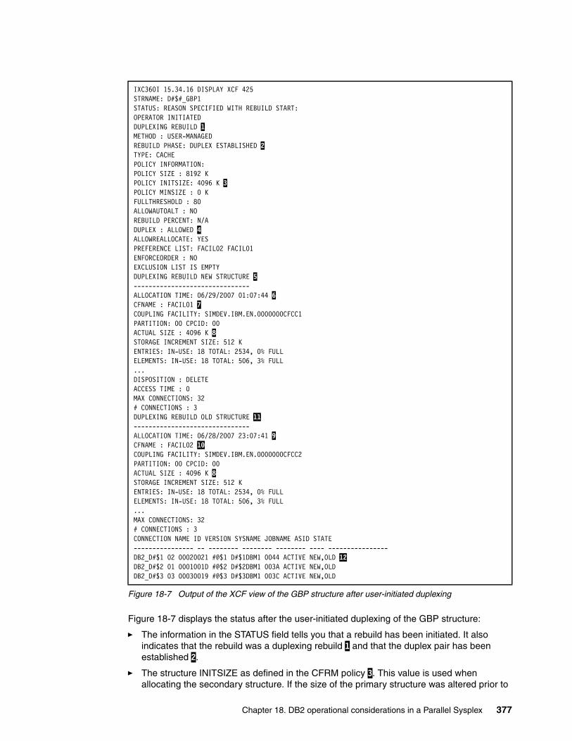
Figure 18-7 Output of the XCF view of the GBP structure after user-initiated duplexing
Figure 18-7 displays the status after the user-initiated duplexing of the GBP structure:
� The information in the STATUS field tells you that a rebuild has been initiated. It also indicates that the rebuild was a duplexing rebuild 1 and that the duplex pair has been established 2.
� The structure INITSIZE as defined in the CFRM policy 3. This value is used when allocating the secondary structure. If the size of the primary structure was altered prior to
IXC360I 15.34.16 DISPLAY XCF 425STRNAME: D#$#_GBP1STATUS: REASON SPECIFIED WITH REBUILD START:OPERATOR INITIATEDDUPLEXING REBUILD 1METHOD : USER-MANAGEDREBUILD PHASE: DUPLEX ESTABLISHED 2TYPE: CACHEPOLICY INFORMATION:POLICY SIZE : 8192 KPOLICY INITSIZE: 4096 K 3POLICY MINSIZE : 0 KFULLTHRESHOLD : 80ALLOWAUTOALT : NOREBUILD PERCENT: N/ADUPLEX : ALLOWED 4ALLOWREALLOCATE: YESPREFERENCE LIST: FACIL02 FACIL01ENFORCEORDER : NOEXCLUSION LIST IS EMPTYDUPLEXING REBUILD NEW STRUCTURE 5-------------------------------ALLOCATION TIME: 06/29/2007 01:07:44 6CFNAME : FACIL01 7COUPLING FACILITY: SIMDEV.IBM.EN.0000000CFCC1PARTITION: 00 CPCID: 00ACTUAL SIZE : 4096 K 8STORAGE INCREMENT SIZE: 512 KENTRIES: IN-USE: 18 TOTAL: 2534, 0% FULLELEMENTS: IN-USE: 18 TOTAL: 506, 3% FULL...DISPOSITION : DELETEACCESS TIME : 0MAX CONNECTIONS: 32# CONNECTIONS : 3DUPLEXING REBUILD OLD STRUCTURE 11-------------------------------ALLOCATION TIME: 06/28/2007 23:07:41 9CFNAME : FACIL02 10COUPLING FACILITY: SIMDEV.IBM.EN.0000000CFCC2PARTITION: 00 CPCID: 00ACTUAL SIZE : 4096 K 8STORAGE INCREMENT SIZE: 512 KENTRIES: IN-USE: 18 TOTAL: 2534, 0% FULLELEMENTS: IN-USE: 18 TOTAL: 506, 3% FULL...MAX CONNECTIONS: 32# CONNECTIONS : 3CONNECTION NAME ID VERSION SYSNAME JOBNAME ASID STATE---------------- -- -------- -------- -------- ---- ----------------DB2_D#$1 02 00020021 #@$1 D#$1DBM1 0044 ACTIVE NEW,OLD 12DB2_D#$2 01 0001001D #@$2 D#$2DBM1 003A ACTIVE NEW,OLD DB2_D#$3 03 00030019 #@$3 D#$3DBM1 003C ACTIVE NEW,OLD
Chapter 18. DB2 operational considerations in a Parallel Sysplex 377
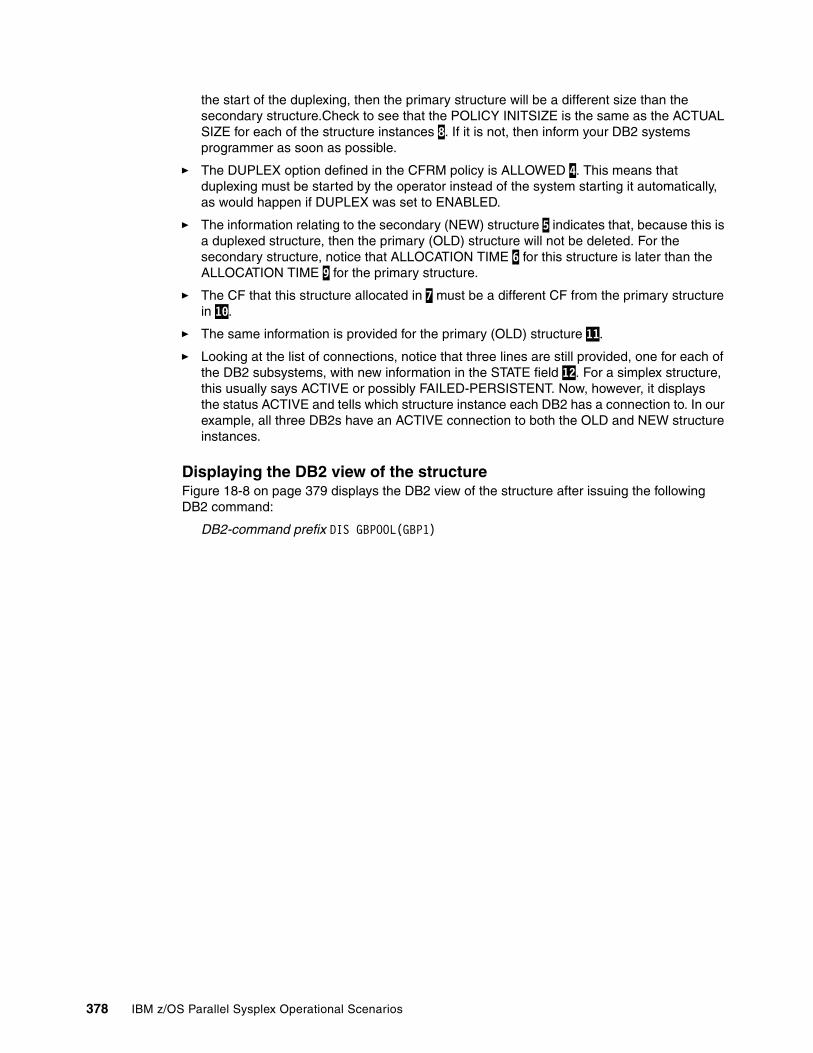
the start of the duplexing, then the primary structure will be a different size than the secondary structure.Check to see that the POLICY INITSIZE is the same as the ACTUAL SIZE for each of the structure instances 8. If it is not, then inform your DB2 systems programmer as soon as possible.
� The DUPLEX option defined in the CFRM policy is ALLOWED 4. This means that duplexing must be started by the operator instead of the system starting it automatically, as would happen if DUPLEX was set to ENABLED.
� The information relating to the secondary (NEW) structure 5 indicates that, because this is a duplexed structure, then the primary (OLD) structure will not be deleted. For the secondary structure, notice that ALLOCATION TIME 6 for this structure is later than the ALLOCATION TIME 9 for the primary structure.
� The CF that this structure allocated in 7 must be a different CF from the primary structure in 10.
� The same information is provided for the primary (OLD) structure 11.
� Looking at the list of connections, notice that three lines are still provided, one for each of the DB2 subsystems, with new information in the STATE field 12. For a simplex structure, this usually says ACTIVE or possibly FAILED-PERSISTENT. Now, however, it displays the status ACTIVE and tells which structure instance each DB2 has a connection to. In our example, all three DB2s have an ACTIVE connection to both the OLD and NEW structure instances.
Displaying the DB2 view of the structureFigure 18-8 on page 379 displays the DB2 view of the structure after issuing the following DB2 command:
DB2-command prefix DIS GBPOOL(GBP1)
378 IBM z/OS Parallel Sysplex Operational Scenarios
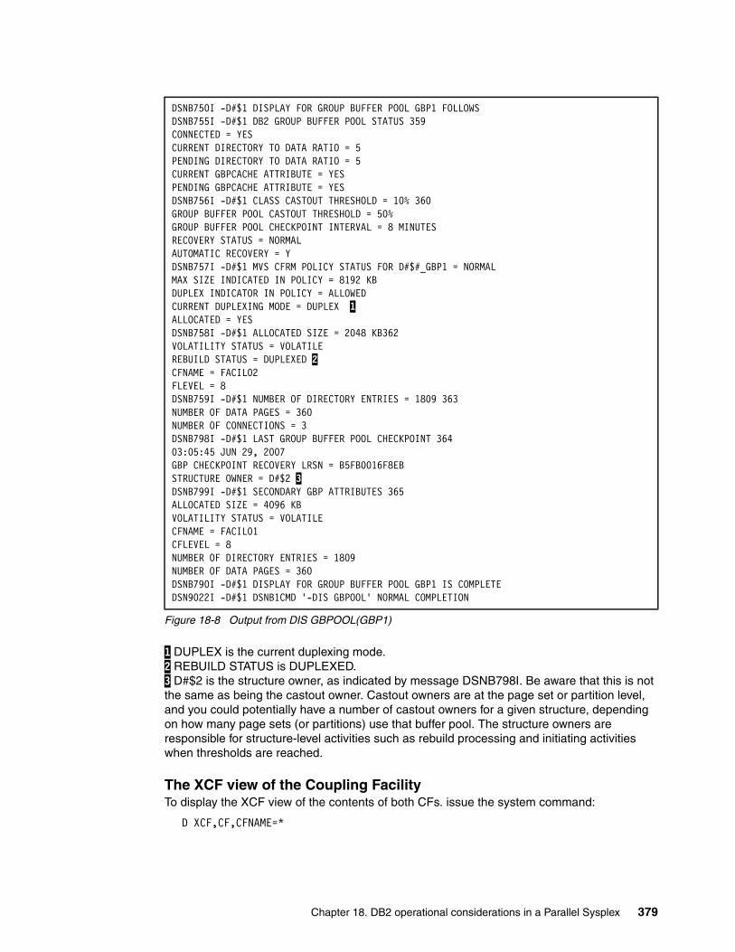
Figure 18-8 Output from DIS GBPOOL(GBP1)
1 DUPLEX is the current duplexing mode. 2 REBUILD STATUS is DUPLEXED. 3 D#$2 is the structure owner, as indicated by message DSNB798I. Be aware that this is not the same as being the castout owner. Castout owners are at the page set or partition level, and you could potentially have a number of castout owners for a given structure, depending on how many page sets (or partitions) use that buffer pool. The structure owners are responsible for structure-level activities such as rebuild processing and initiating activities when thresholds are reached.
The XCF view of the Coupling FacilityTo display the XCF view of the contents of both CFs. issue the system command:
D XCF,CF,CFNAME=*
DSNB750I -D#$1 DISPLAY FOR GROUP BUFFER POOL GBP1 FOLLOWSDSNB755I -D#$1 DB2 GROUP BUFFER POOL STATUS 359CONNECTED = YESCURRENT DIRECTORY TO DATA RATIO = 5PENDING DIRECTORY TO DATA RATIO = 5CURRENT GBPCACHE ATTRIBUTE = YESPENDING GBPCACHE ATTRIBUTE = YESDSNB756I -D#$1 CLASS CASTOUT THRESHOLD = 10% 360GROUP BUFFER POOL CASTOUT THRESHOLD = 50%GROUP BUFFER POOL CHECKPOINT INTERVAL = 8 MINUTESRECOVERY STATUS = NORMALAUTOMATIC RECOVERY = YDSNB757I -D#$1 MVS CFRM POLICY STATUS FOR D#$#_GBP1 = NORMALMAX SIZE INDICATED IN POLICY = 8192 KBDUPLEX INDICATOR IN POLICY = ALLOWEDCURRENT DUPLEXING MODE = DUPLEX 1ALLOCATED = YESDSNB758I -D#$1 ALLOCATED SIZE = 2048 KB362VOLATILITY STATUS = VOLATILEREBUILD STATUS = DUPLEXED 2CFNAME = FACIL02FLEVEL = 8DSNB759I -D#$1 NUMBER OF DIRECTORY ENTRIES = 1809 363NUMBER OF DATA PAGES = 360NUMBER OF CONNECTIONS = 3DSNB798I -D#$1 LAST GROUP BUFFER POOL CHECKPOINT 36403:05:45 JUN 29, 2007GBP CHECKPOINT RECOVERY LRSN = B5FB0016F8EBSTRUCTURE OWNER = D#$2 3DSNB799I -D#$1 SECONDARY GBP ATTRIBUTES 365ALLOCATED SIZE = 4096 KBVOLATILITY STATUS = VOLATILECFNAME = FACIL01CFLEVEL = 8NUMBER OF DIRECTORY ENTRIES = 1809NUMBER OF DATA PAGES = 360DSNB790I -D#$1 DISPLAY FOR GROUP BUFFER POOL GBP1 IS COMPLETEDSN9022I -D#$1 DSNB1CMD '-DIS GBPOOL' NORMAL COMPLETION
Chapter 18. DB2 operational considerations in a Parallel Sysplex 379
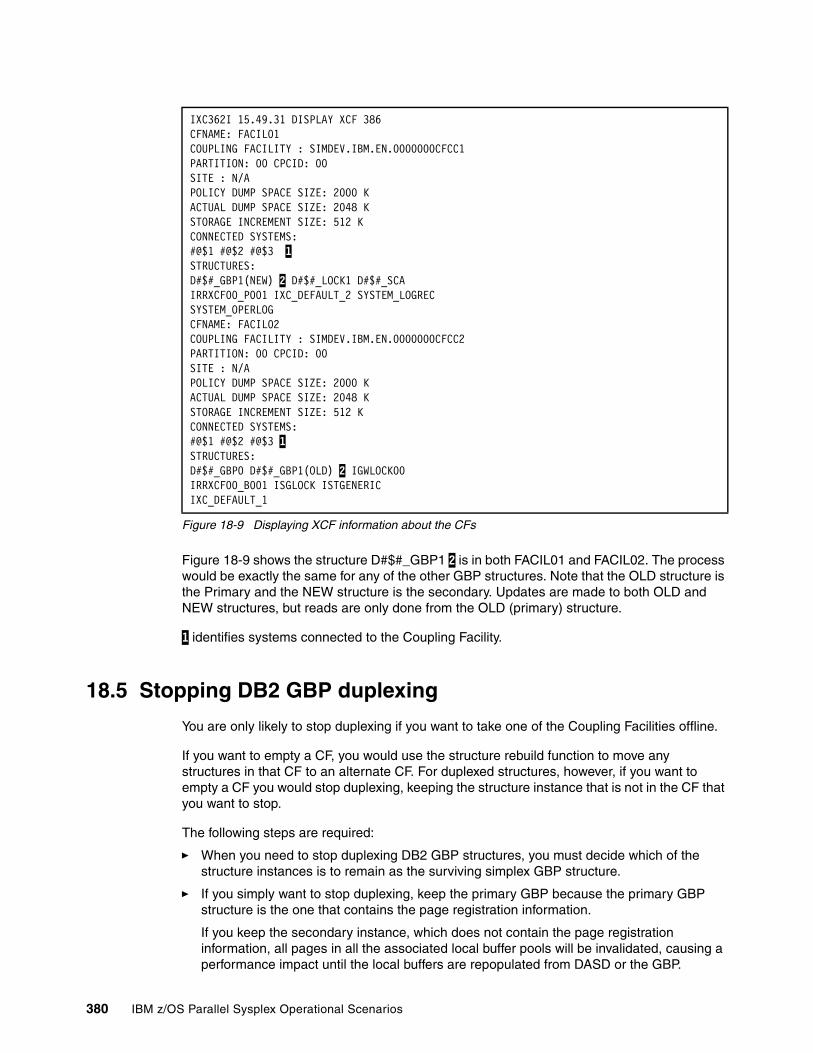
Figure 18-9 Displaying XCF information about the CFs
Figure 18-9 shows the structure D#$#_GBP1 2 is in both FACIL01 and FACIL02. The process would be exactly the same for any of the other GBP structures. Note that the OLD structure is the Primary and the NEW structure is the secondary. Updates are made to both OLD and NEW structures, but reads are only done from the OLD (primary) structure.
1 identifies systems connected to the Coupling Facility.
18.5 Stopping DB2 GBP duplexing
You are only likely to stop duplexing if you want to take one of the Coupling Facilities offline.
If you want to empty a CF, you would use the structure rebuild function to move any structures in that CF to an alternate CF. For duplexed structures, however, if you want to empty a CF you would stop duplexing, keeping the structure instance that is not in the CF that you want to stop.
The following steps are required:
� When you need to stop duplexing DB2 GBP structures, you must decide which of the structure instances is to remain as the surviving simplex GBP structure.
� If you simply want to stop duplexing, keep the primary GBP because the primary GBP structure is the one that contains the page registration information.
If you keep the secondary instance, which does not contain the page registration information, all pages in all the associated local buffer pools will be invalidated, causing a performance impact until the local buffers are repopulated from DASD or the GBP.
IXC362I 15.49.31 DISPLAY XCF 386CFNAME: FACIL01COUPLING FACILITY : SIMDEV.IBM.EN.0000000CFCC1PARTITION: 00 CPCID: 00SITE : N/APOLICY DUMP SPACE SIZE: 2000 KACTUAL DUMP SPACE SIZE: 2048 KSTORAGE INCREMENT SIZE: 512 KCONNECTED SYSTEMS:#@$1 #@$2 #@$3 1STRUCTURES:D#$#_GBP1(NEW) 2 D#$#_LOCK1 D#$#_SCAIRRXCF00_P001 IXC_DEFAULT_2 SYSTEM_LOGRECSYSTEM_OPERLOGCFNAME: FACIL02COUPLING FACILITY : SIMDEV.IBM.EN.0000000CFCC2PARTITION: 00 CPCID: 00SITE : N/APOLICY DUMP SPACE SIZE: 2000 KACTUAL DUMP SPACE SIZE: 2048 KSTORAGE INCREMENT SIZE: 512 KCONNECTED SYSTEMS:#@$1 #@$2 #@$3 1STRUCTURES:D#$#_GBP0 D#$#_GBP1(OLD) 2 IGWLOCK00IRRXCF00_B001 ISGLOCK ISTGENERICIXC_DEFAULT_1
380 IBM z/OS Parallel Sysplex Operational Scenarios
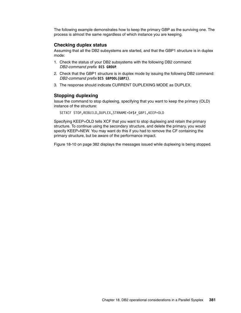
The following example demonstrates how to keep the primary GBP as the surviving one. The process is almost the same regardless of which instance you are keeping.
Checking duplex statusAssuming that all the DB2 subsystems are started, and that the GBP1 structure is in duplex mode:
1. Check the status of your DB2 subsystems with the following DB2 command: DB2-command prefix DIS GROUP.
2. Check that the GBP1 structure is in duplex mode by issuing the following DB2 command: DB2-command prefix DIS GBPOOL(GBP1).
3. The response should indicate CURRENT DUPLEXING MODE as DUPLEX.
Stopping duplexingIssue the command to stop duplexing, specifying that you want to keep the primary (OLD) instance of the structure:
SETXCF STOP,REBUILD,DUPLEX,STRNAME=D#$#_GBP1,KEEP=OLD
Specifying KEEP=OLD tells XCF that you want to stop duplexing and retain the primary structure. To continue using the secondary structure, and delete the primary, you would specify KEEP=NEW. You may want do this if you had to remove the CF containing the primary structure, but be aware of the performance impact.
Figure 18-10 on page 382 displays the messages issued while duplexing is being stopped.
Chapter 18. DB2 operational considerations in a Parallel Sysplex 381
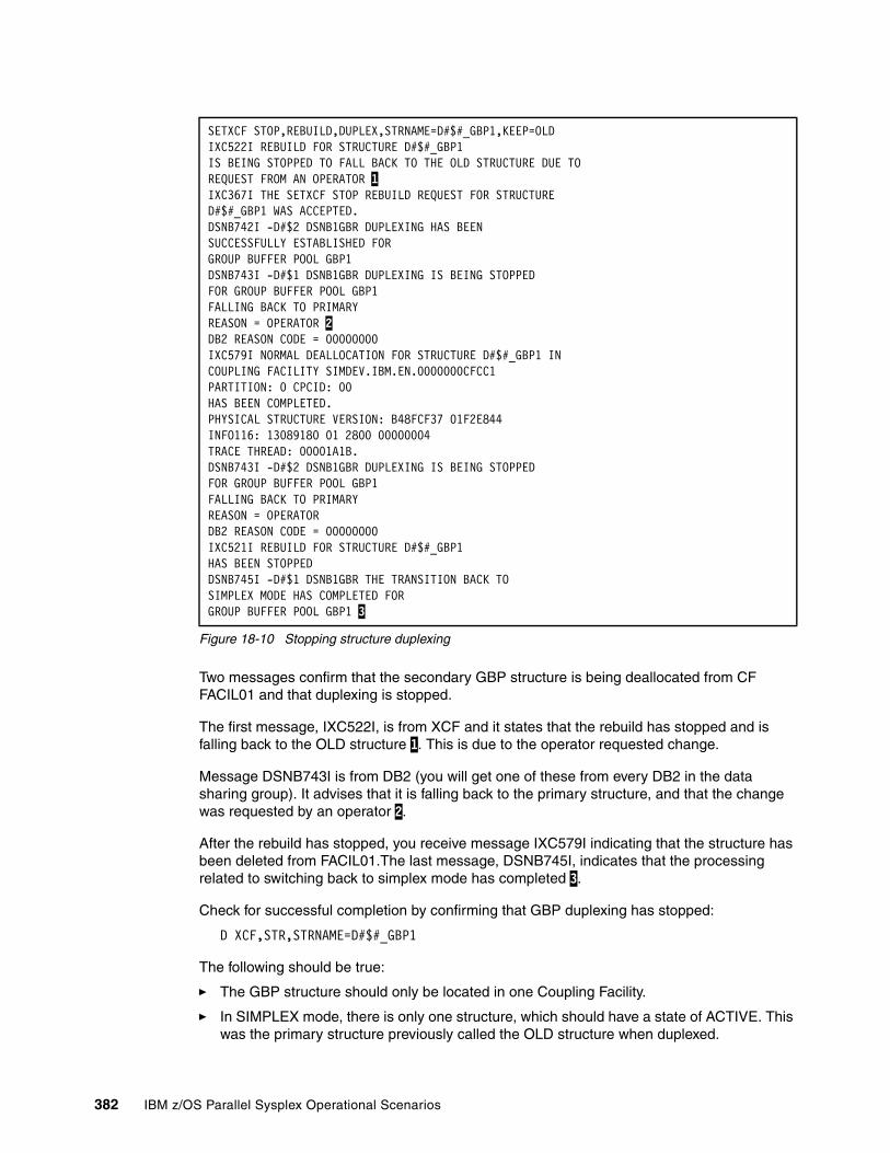
Figure 18-10 Stopping structure duplexing
Two messages confirm that the secondary GBP structure is being deallocated from CF FACIL01 and that duplexing is stopped.
The first message, IXC522I, is from XCF and it states that the rebuild has stopped and is falling back to the OLD structure 1. This is due to the operator requested change.
Message DSNB743I is from DB2 (you will get one of these from every DB2 in the data sharing group). It advises that it is falling back to the primary structure, and that the change was requested by an operator 2.
After the rebuild has stopped, you receive message IXC579I indicating that the structure has been deleted from FACIL01.The last message, DSNB745I, indicates that the processing related to switching back to simplex mode has completed 3.
Check for successful completion by confirming that GBP duplexing has stopped:
D XCF,STR,STRNAME=D#$#_GBP1
The following should be true:
� The GBP structure should only be located in one Coupling Facility.
� In SIMPLEX mode, there is only one structure, which should have a state of ACTIVE. This was the primary structure previously called the OLD structure when duplexed.
SETXCF STOP,REBUILD,DUPLEX,STRNAME=D#$#_GBP1,KEEP=OLDIXC522I REBUILD FOR STRUCTURE D#$#_GBP1IS BEING STOPPED TO FALL BACK TO THE OLD STRUCTURE DUE TOREQUEST FROM AN OPERATOR 1IXC367I THE SETXCF STOP REBUILD REQUEST FOR STRUCTURED#$#_GBP1 WAS ACCEPTED.DSNB742I -D#$2 DSNB1GBR DUPLEXING HAS BEENSUCCESSFULLY ESTABLISHED FORGROUP BUFFER POOL GBP1DSNB743I -D#$1 DSNB1GBR DUPLEXING IS BEING STOPPEDFOR GROUP BUFFER POOL GBP1FALLING BACK TO PRIMARYREASON = OPERATOR 2DB2 REASON CODE = 00000000IXC579I NORMAL DEALLOCATION FOR STRUCTURE D#$#_GBP1 INCOUPLING FACILITY SIMDEV.IBM.EN.0000000CFCC1 PARTITION: 0 CPCID: 00HAS BEEN COMPLETED.PHYSICAL STRUCTURE VERSION: B48FCF37 01F2E844INFO116: 13089180 01 2800 00000004TRACE THREAD: 00001A1B.DSNB743I -D#$2 DSNB1GBR DUPLEXING IS BEING STOPPEDFOR GROUP BUFFER POOL GBP1FALLING BACK TO PRIMARYREASON = OPERATORDB2 REASON CODE = 00000000IXC521I REBUILD FOR STRUCTURE D#$#_GBP1HAS BEEN STOPPEDDSNB745I -D#$1 DSNB1GBR THE TRANSITION BACK TOSIMPLEX MODE HAS COMPLETED FORGROUP BUFFER POOL GBP1 3
382 IBM z/OS Parallel Sysplex Operational Scenarios
Displaying the GBP structure status in DB2Display the DB2 view of the structure by using the following DB2 command:
DB2-command prefix DIS GBPOOL(GBP1)
The output displayed in Figure 18-11 now shows that the 1 CURRENT DUPLEXING MODE is SIMPLEX and the location of this structure 2 is FACIL02.
Figure 18-11 Output from DISPLAY GBPOOL command
18.6 Modifying the GBP structure size
There are two methods for changing the size of GBP structures, static and dynamic. Using the static method, the size of the structure in the CFRM policy is modified and then rebuilt with the SETXCF START,REBUILD command. An alternative MVS command, SETXCF START,REALLOCATE, will resolve all pending changes from the activation of a new policy. (Be aware, however, that the SETXCF START,REALLOCATE command may reposition structures that other people are working with.)
The main characteristics of the static method are:
� It is permanent. If the structure is deleted and allocated again, it will still have the new size.
� If the actual size of the structure has already reached the SIZE value specified in the CFRM policy, this is the only way to make it larger.
-D#$3 DISPLAY FOR GROUP BUFFER POOL GBP1 FOLLOWS -D#$3 DB2 GROUP BUFFER POOL STATUS CONNECTED = NO CURRENT DIRECTORY TO DATA RATIO = 6 PENDING DIRECTORY TO DATA RATIO = 6 CURRENT GBPCACHE ATTRIBUTE = YES PENDING GBPCACHE ATTRIBUTE = YES -D#$3 CLASS CASTOUT THRESHOLD = 10% GROUP BUFFER POOL CASTOUT THRESHOLD = 50% GROUP BUFFER POOL CHECKPOINT INTERVAL = 8 MINUTES RECOVERY STATUS = NORMAL AUTOMATIC RECOVERY = Y -D#$3 MVS CFRM POLICY STATUS FOR D#$#_GBP1 = NORMAL MAX SIZE INDICATED IN POLICY = 8192 KB DUPLEX INDICATOR IN POLICY = ENABLED CURRENT DUPLEXING MODE = SIMPLEX 1 ALLOCATED = YES -D#$3 ALLOCATED SIZE = 4096 KB VOLATILITY STATUS = VOLATILE REBUILD STATUS = NONE CFNAME = FACIL02 2 CFLEVEL - OPERATIONAL = 14 CFLEVEL - ACTUAL = 14 -D#$3 NUMBER OF DIRECTORY ENTRIES = 3241 NUMBER OF DATA PAGES = 538 NUMBER OF CONNECTIONS = 1 -D#$3 LAST GROUP BUFFER POOL CHECKPOINT 18:14:20 JUL 5, 2007 GBP CHECKPOINT RECOVERY LRSN = C0D9BAC2655E STRUCTURE OWNER = -D#$3 DISPLAY FOR GROUP BUFFER POOL GBP1 IS COMPLETE -D#$3 DSNB1CMD '-DIS GBPOOL' NORMAL COMPLETION
Chapter 18. DB2 operational considerations in a Parallel Sysplex 383
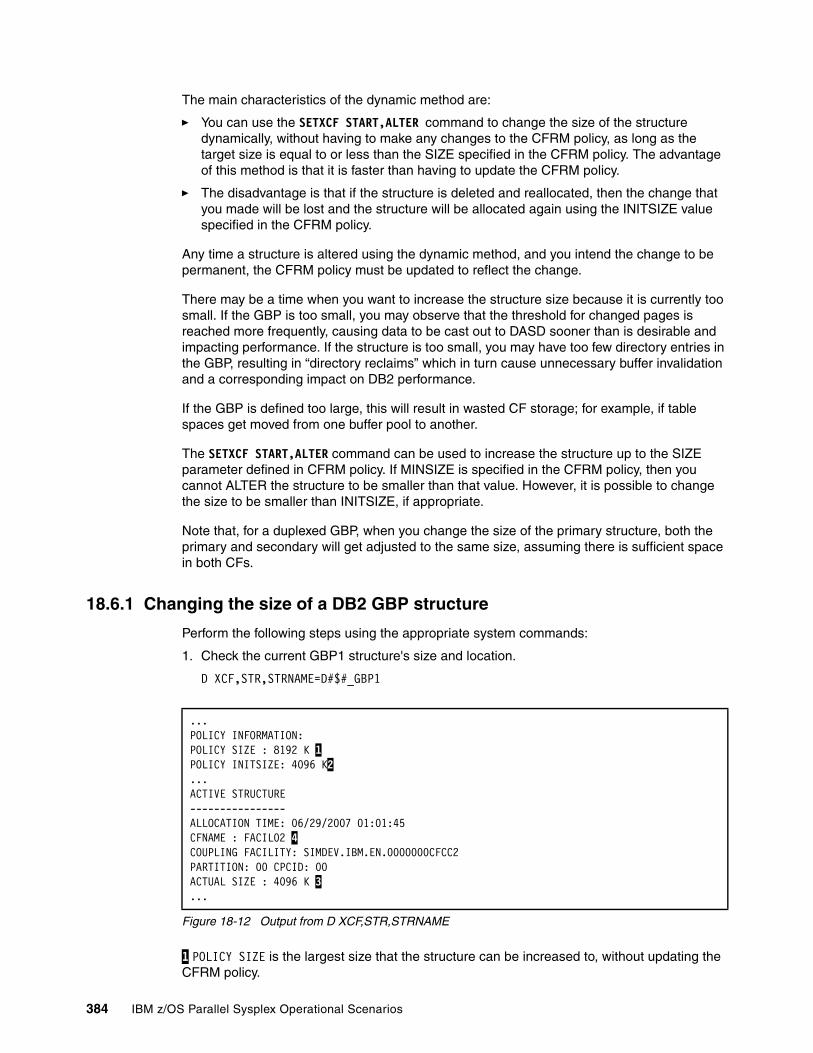
The main characteristics of the dynamic method are:
� You can use the SETXCF START,ALTER command to change the size of the structure dynamically, without having to make any changes to the CFRM policy, as long as the target size is equal to or less than the SIZE specified in the CFRM policy. The advantage of this method is that it is faster than having to update the CFRM policy.
� The disadvantage is that if the structure is deleted and reallocated, then the change that you made will be lost and the structure will be allocated again using the INITSIZE value specified in the CFRM policy.
Any time a structure is altered using the dynamic method, and you intend the change to be permanent, the CFRM policy must be updated to reflect the change.
There may be a time when you want to increase the structure size because it is currently too small. If the GBP is too small, you may observe that the threshold for changed pages is reached more frequently, causing data to be cast out to DASD sooner than is desirable and impacting performance. If the structure is too small, you may have too few directory entries in the GBP, resulting in “directory reclaims” which in turn cause unnecessary buffer invalidation and a corresponding impact on DB2 performance.
If the GBP is defined too large, this will result in wasted CF storage; for example, if table spaces get moved from one buffer pool to another.
The SETXCF START,ALTER command can be used to increase the structure up to the SIZE parameter defined in CFRM policy. If MINSIZE is specified in the CFRM policy, then you cannot ALTER the structure to be smaller than that value. However, it is possible to change the size to be smaller than INITSIZE, if appropriate.
Note that, for a duplexed GBP, when you change the size of the primary structure, both the primary and secondary will get adjusted to the same size, assuming there is sufficient space in both CFs.
18.6.1 Changing the size of a DB2 GBP structure
Perform the following steps using the appropriate system commands:
1. Check the current GBP1 structure's size and location.
D XCF,STR,STRNAME=D#$#_GBP1
Figure 18-12 Output from D XCF,STR,STRNAME
1 POLICY SIZE is the largest size that the structure can be increased to, without updating the CFRM policy.
...POLICY INFORMATION:POLICY SIZE : 8192 K 1POLICY INITSIZE: 4096 K2...ACTIVE STRUCTURE----------------ALLOCATION TIME: 06/29/2007 01:01:45CFNAME : FACIL02 4COUPLING FACILITY: SIMDEV.IBM.EN.0000000CFCC2PARTITION: 00 CPCID: 00ACTUAL SIZE : 4096 K 3...
384 IBM z/OS Parallel Sysplex Operational Scenarios
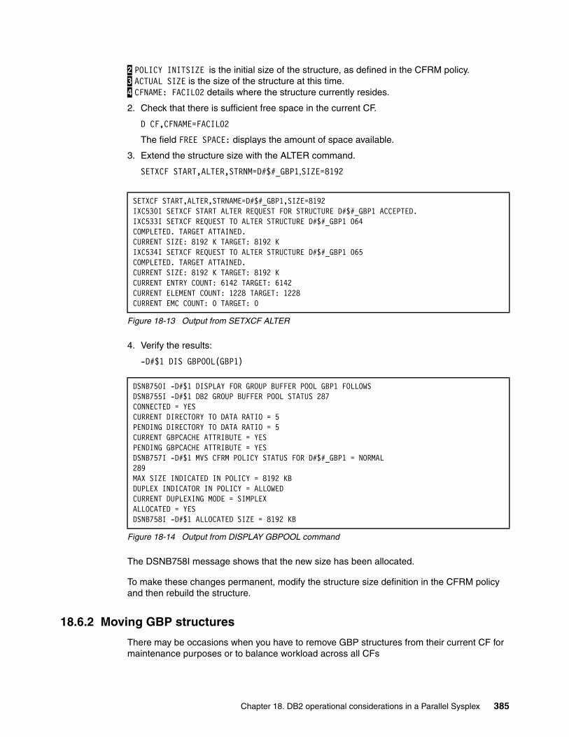
2 POLICY INITSIZE is the initial size of the structure, as defined in the CFRM policy. 3 ACTUAL SIZE is the size of the structure at this time. 4 CFNAME: FACIL02 details where the structure currently resides.
2. Check that there is sufficient free space in the current CF.
D CF,CFNAME=FACIL02
The field FREE SPACE: displays the amount of space available.
3. Extend the structure size with the ALTER command.
SETXCF START,ALTER,STRNM=D#$#_GBP1,SIZE=8192
Figure 18-13 Output from SETXCF ALTER
4. Verify the results:
-D#$1 DIS GBPOOL(GBP1)
Figure 18-14 Output from DISPLAY GBPOOL command
The DSNB758I message shows that the new size has been allocated.
To make these changes permanent, modify the structure size definition in the CFRM policy and then rebuild the structure.
18.6.2 Moving GBP structures
There may be occasions when you have to remove GBP structures from their current CF for maintenance purposes or to balance workload across all CFs
SETXCF START,ALTER,STRNAME=D#$#_GBP1,SIZE=8192IXC530I SETXCF START ALTER REQUEST FOR STRUCTURE D#$#_GBP1 ACCEPTED.IXC533I SETXCF REQUEST TO ALTER STRUCTURE D#$#_GBP1 064COMPLETED. TARGET ATTAINED.CURRENT SIZE: 8192 K TARGET: 8192 KIXC534I SETXCF REQUEST TO ALTER STRUCTURE D#$#_GBP1 065COMPLETED. TARGET ATTAINED.CURRENT SIZE: 8192 K TARGET: 8192 KCURRENT ENTRY COUNT: 6142 TARGET: 6142CURRENT ELEMENT COUNT: 1228 TARGET: 1228CURRENT EMC COUNT: 0 TARGET: 0
DSNB750I -D#$1 DISPLAY FOR GROUP BUFFER POOL GBP1 FOLLOWSDSNB755I -D#$1 DB2 GROUP BUFFER POOL STATUS 287CONNECTED = YESCURRENT DIRECTORY TO DATA RATIO = 5PENDING DIRECTORY TO DATA RATIO = 5CURRENT GBPCACHE ATTRIBUTE = YESPENDING GBPCACHE ATTRIBUTE = YESDSNB757I -D#$1 MVS CFRM POLICY STATUS FOR D#$#_GBP1 = NORMAL289MAX SIZE INDICATED IN POLICY = 8192 KBDUPLEX INDICATOR IN POLICY = ALLOWEDCURRENT DUPLEXING MODE = SIMPLEXALLOCATED = YESDSNB758I -D#$1 ALLOCATED SIZE = 8192 KB
Chapter 18. DB2 operational considerations in a Parallel Sysplex 385
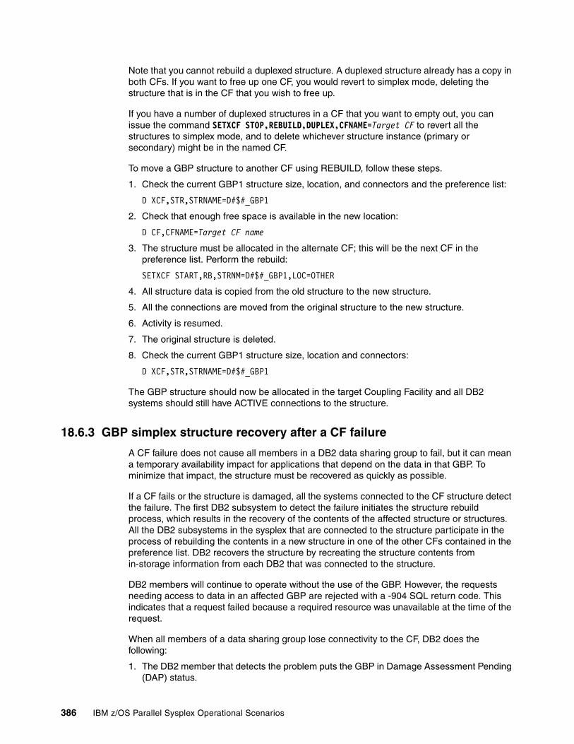
Note that you cannot rebuild a duplexed structure. A duplexed structure already has a copy in both CFs. If you want to free up one CF, you would revert to simplex mode, deleting the structure that is in the CF that you wish to free up.
If you have a number of duplexed structures in a CF that you want to empty out, you can issue the command SETXCF STOP,REBUILD,DUPLEX,CFNAME=Target CF to revert all the structures to simplex mode, and to delete whichever structure instance (primary or secondary) might be in the named CF.
To move a GBP structure to another CF using REBUILD, follow these steps.
1. Check the current GBP1 structure size, location, and connectors and the preference list:
D XCF,STR,STRNAME=D#$#_GBP1
2. Check that enough free space is available in the new location:
D CF,CFNAME=Target CF name
3. The structure must be allocated in the alternate CF; this will be the next CF in the preference list. Perform the rebuild:
SETXCF START,RB,STRNM=D#$#_GBP1,LOC=OTHER
4. All structure data is copied from the old structure to the new structure.
5. All the connections are moved from the original structure to the new structure.
6. Activity is resumed.
7. The original structure is deleted.
8. Check the current GBP1 structure size, location and connectors:
D XCF,STR,STRNAME=D#$#_GBP1
The GBP structure should now be allocated in the target Coupling Facility and all DB2 systems should still have ACTIVE connections to the structure.
18.6.3 GBP simplex structure recovery after a CF failure
A CF failure does not cause all members in a DB2 data sharing group to fail, but it can mean a temporary availability impact for applications that depend on the data in that GBP. To minimize that impact, the structure must be recovered as quickly as possible.
If a CF fails or the structure is damaged, all the systems connected to the CF structure detect the failure. The first DB2 subsystem to detect the failure initiates the structure rebuild process, which results in the recovery of the contents of the affected structure or structures. All the DB2 subsystems in the sysplex that are connected to the structure participate in the process of rebuilding the contents in a new structure in one of the other CFs contained in the preference list. DB2 recovers the structure by recreating the structure contents from in-storage information from each DB2 that was connected to the structure.
DB2 members will continue to operate without the use of the GBP. However, the requests needing access to data in an affected GBP are rejected with a -904 SQL return code. This indicates that a request failed because a required resource was unavailable at the time of the request.
When all members of a data sharing group lose connectivity to the CF, DB2 does the following:
1. The DB2 member that detects the problem puts the GBP in Damage Assessment Pending (DAP) status.
386 IBM z/OS Parallel Sysplex Operational Scenarios
2. DB2 adds entries to the Logical Page List (LPL), if required.
3. The Damage Assessment process determines which page sets were group-buffer-pool-dependent and places them in Group Recovery Pending (GRECP) status. As long as the resource remains in GRECP status, it is inaccessible to any application program.
4. START DATABASE commands are automatically issued by DB2 to recover all table spaces from the GRECP status. If this does not cause successful recovery, you may have to issue the START DATABASE command manually.
5. The GBP Damage Assessment Pending (DAP) status is reset.
DB2 terminology for DAP statusThe DB2 terminology used for Damage Assessment Pending status is explained here:
� Damage Assessment Pending (DAP)
The GBP uses information in the lock structure and SCA to determine which databases must be recovered. The Shared Communication Area (SCA) is a list structure used by all data sharing group members to pass control information back and forth. The SCA is also used to provide recovery of the data sharing group.
� Logical Page List (LPL)
Some pages were not read from or written to the GBP because of a failure, such as complete loss of link connectivity between the GBP and the processor, or some pages could not be read from or written to DASD because of a DASD problem. Typically, only write problems result in LPL pages and the LPL list is kept in the database exception table (DBET) in the Shared Communication Area.
� GBP Recovery Pending (GRECP)
This indicates that the GBP failed, and the changes that are recorded in the log must be applied to the page set. When a page set is placed in the GRECP status, DB2 sets the starting point for the merge log scan to the Log Record Sequence Number (LSRN) of the last complete GBP checkpoint.
After you have recovered the failed CF, move all the structures that normally reside there back to that CF by using the system command:
SETXCF START,REBUILD,POPCF=Target CF
The recovery process for a duplexed structure is different and significantly faster. In that case, DB2 simply reverts to simplex mode and continues processing using the surviving structure instance.
18.6.4 GBP duplex structure recovery from a CF failure
To minimize the impact from a CF failure, structures can be duplexed. Duplexing will speed up the recovery process because the secondary structure will already be allocated and will contain updated data.
Note that a secondary structure is not an exact copy of the primary. Although it does contain updated data, if the primary structure fails, there still has to be a rebuild phase to the secondary structure.
Chapter 18. DB2 operational considerations in a Parallel Sysplex 387
18.7 SCA structure management and recovery
This section discusses the management and recovery of the list structure.
18.7.1 SCA list structure
There is one list structure per data sharing group used as the shared communications area (SCA) for the members of the group. The SCA contains information about databases in an exception condition and recovery information for each data sharing group member. This information may include:
� Logical Page List (LPL) � Database Exception Table (DBET) � Boot Strap Data Set (BSDS) - names of all members � Log data set - names of all members � LRSN delta � Copy Pending � Write Error ranges � Image copy data for certain system data spaces
This information is available to all members of the data sharing group. Other DB2s have the ability to recover information from a failure during a group-wide restart if one of the DB2 is not restarted. This is known as a “Peer Restart” of the Current Status Rebuild phase of DB2 restart.
The DB2 member performing the Peer Restart needs to know the log information about the non-starting member. It finds this out by reading the SCA structure. The first connector to the structure is responsible for building the structure if it does not exist.
The SCA structure supports REBUILDPERCENT and automatic rebuild, if the SFM policy is defined with CONNFAIL(YES) specified. Manual rebuild is supported using the SETXCF START,REBUILD command without stopping the data sharing group members.
18.7.2 Allocating the SCA structure
DB2 rebuilds the SCA structure from information in the bootstrap data set BSDS, and also from information in the storage of any connected DB2s. If you lose the SCA and one of the DB2s, the structure cannot be rebuilt so you must perform a group restart. To avoid a group restart for this type of condition, you can exploit System Managed CF Duplexing for the SCA structure.
When DB2 starts, the SCA structure called Group attachment name_SCA gets built by the first connector to allocate it, if it does not already exist. The preference list defined in the active CFRM policy determines which CF is chosen.
18.7.3 Removing the SCA structure
After stopping all DB2 members of a data sharing group normally, all connections to the SCA structure will be terminated. The structure itself, however, will not be deleted because its disposition is KEEP.
388 IBM z/OS Parallel Sysplex Operational Scenarios
To remove the structure from a Coupling Facility to perform maintenance on it, use the SETXCF START,REBUILD command to move it to the other CF. Although not recommended, it is possible to remove the SCA structure using the command:
SETXCF FORCE,STR,STRNAME=Group attachment name_SCA
18.7.4 Altering the size of a DB2 SCA
There are two methods of altering the size of the SCA, static or dynamic. The static method entails changing the size of the structure in the CFRM policy and then rebuilding using SETXCF START,REBUILD command. This could be used if:
� The currently allocated size of the structure has reached the maximum size defined in the SIZE parameter of the CFRM policy.
� The initial size of a structure is not correct and always has to be adjusted. In this case, a static change to INITSIZE would be required.
The dynamic method uses the SETXCF START,ALTER command or the autoalter function defined in the CFRM to change the size of the SCA, but only if the currently allocated size of the structure is less than the maximum size as defined in the SIZE parameter of the CFRM policy. An SCA that is too small may cause DB2 to crash.
18.7.5 Moving the SCA structure
It may be necessary to move a structure from one CF to another for workload rebalancing, or to move all the structures out of a CF for maintenance purposes. This can be done dynamically.
During the move, all activity to the SCA structure is temporarily stopped while a new structure is allocated on the target CF and the contents of the old structure are copied to the new one. The connections are established to the new structure, and finally the old structure is deallocated. This is all handled by the system after you initiate the SETXCF START,REBUILD command.
If the current size of the SCA structure is different from the INITSIZE (the structure size was changed using the SETXCF ALTER command), the rebuild will attempt to allocate the structure in the new CF with the same size that was in the previous CF.
18.7.6 SCA over threshold condition
When an unusually large amount of exception type or recovery-related conditions occur, the SCA structure may need to be increased in size. If the SCA structure size is not increased in a timely fashion, it may cause the DB2 subsystems to crash. Structure monitoring will
Note: We do not recommend deleting the SCA structure (even though it is possible to do so). If there is a catastrophic failure and all DB2s in the data sharing group come down without resource cleanup, then the recovery information needed to perform a peer recovery is still available. When a DB2 restarts, it will have the names of the logs of the other DB2s, what the current location in the logs are, where the oldest unit of recovery is, and other recovery information in the SCA.
Note: The rebuild of the SCA structure is dynamic and nondisruptive to DB2.
Chapter 18. DB2 operational considerations in a Parallel Sysplex 389

produce highlighted warning messages on the MCS console when the structure reaches its threshold The default threshold is 80% full for the SCA structure. If the SCA is too small, DB2 may crash.
18.7.7 SCA recovery from a CF failure
In the event of a single CF failure, if a dual CF is used, a dynamic rebuild of the SCA structure would be initiated and it will be possible to recover from the failure. If a single CF were used, then the DB2 members using the SCA structure would come down.
To minimize the impact of CF failures:
� Have an active SFM policy. � Use dual Coupling Facilities.� Have enough space on each CF to back up the structures on the other CF.� Use duplexing for the GBPs, SCA, and Lock structures.� Use dual paths to help prevent connectivity failures.
Even though the DB2 system remains operational, processes that require access to the SCA structures are queued while DB2 is rebuilding the SCA. This is the same for Lock and GBP structures.
18.7.8 SCA recovery from a system failure
In the event of a DB2 subsystem or system failure, the SCA structure will remain active and usable to the surviving DB2 members. See 18.9.6, “DB2 restart with Restart Light” on page 393 for more detailed information about this topic.
18.8 How DB2 and IRLM use the CF for locking
IRLM is shipped with DB2. Each DB2 subsystem must have its own instance of IRLM. Note that IRLM has its own version and release numbering system, which does not correspond one-to-one to DB2 version and release numbering.
You cannot share IRLM between DB2s or between DB2 and IMS. If you are running a DB2 data sharing group, there is a corresponding IRLM group.
IRLM works with DB2 to serialize access to the data. DB2 requests locks from IRLM to ensure data integrity when applications, utilities, commands, and so on attempt to access the same data. There is one IRLM instance per system on which a DB2 member resides.
IRLM will have entries in storage, as well as duplicate entries in the structure. There is only one IRLM lock structure per data sharing group.
In a data sharing environment, DB2 uses global locks so each member knows about the other members' locks. Local locks still exist but they are only for use by a single member for data that is not being shared.
There are two types of global Locks:
� Physical locks (P-locks)
The mechanism that DB2 uses to track Inter-DB2 Read/Write interest in an object is a global lock called a physical lock. P-Locks are:
– Issued for every table open.
390 IBM z/OS Parallel Sysplex Operational Scenarios
– Initiated by DB2, not by transactions.
– Negotiable.
Page P-Locks are used to preserve integrity when two systems are updating the same page as with Row Level Locking. They are also used on the Space Map Page and Index leaf pages.
� Logical locks (L-locks)
Logical locks are also known as transaction locks. They are used to serialize access to data and are owned by the transaction. L-locks are controlled by each members' IRLM.
P-locks and L-locks work independently of each other, although information about them is stored in both the lock table and the Modified Retained List (MRL) parts of the lock structure.
The CF lock structure contains lock information that all group members need to share. The lock structure is comprised of two independent parts:
� Lock table entry (LTE)
The LTE keeps track of global lock contentions. This is where each DB2 member of a data group registers their interest in a resource (for example, table spaces, an index, a partition.) It is often referred to as the hash table.
� IRLM
IRLM uses a hashing algorithm to assign lock entries in the lock table to a resource requested by more than one member. These lock table entries are also known as hash classes. If two different resources hash to the same lock entry, it is referred to as false contention. False contention causes overhead because IRLM must determine whether the contention is real or false. Extra XCF signalling between the systems is a consequence of both real and false contention. A lock table must be of sufficient size to minimize false contention.
18.9 Using DB2 lock structures
Before starting DB2 for data sharing, you must have defined one lock structure in the CFRM policy. This policy determines how and where the structure resources are allocated.
18.9.1 Deallocating DB2 lock structures
When all the DB2 members of a data sharing group terminate normally by DB2 command, all connections to the lock structure will end normally. The connections will be broken normally but the last DB2 system in the group to close down will stay in FAILED-PERSISTENT status.
This is a completely normal circumstance (the connection is waiting to be reestablished.) The restart of any group member will clear that status when it can establish a new connection with the lock structure. This is called current status rebuild Peer Restart.
It is possible that one of the members of the DB2 data sharing group has abended. In this case, the connection would also be in FAILED-PERSISTENT status.
18.9.2 Altering the size of a DB2 lock structure
The size of the DB2 Lock structure may need to be changed due to increased use of DB2, resulting in a requirement for a larger structure. Conversely, possibly the original structure was oversized and needs to be decreased.
Chapter 18. DB2 operational considerations in a Parallel Sysplex 391
When you add new applications or workload to your DB2 data sharing group, you must take into account the size of your lock structure because the number of locks may increase. If the lock structure is too small, IRLM warns you that it is running out of space by issuing the DXR170I message when storage begins to fill.
It is extremely important to avoid having the structure reach 100% full. This condition can cause DB2 locks to fail and lead to severe performance degradation due to false contention. DB2 will continue, but transactions might begin failing with resource unavailable errors and SQL CODE -904. Use of the lock structure should be monitored by using a performance monitor such as the RMF Structure Activity Report.
Perform the following steps to alter the size of a DB2 lock structure using the appropriate z/OS system commands.
1. Check the structure's size and location:
D XCF,STR,STRNAME=D#$#_LOCK1
2. Check that there is sufficient free space in the current CF:
D CF,CFNAME=current CF name
3. Modify the structure size with the ALTER command:
SETXCF START,ALTER,STRNM=D#$#_LOCK1,SIZE=new size
4. Verify the results:
D XCF,STR,STRNAME=D#$#_LOCK1
Check the ACTUAL SIZE value.
18.9.3 Moving DB2 lock structures
It may become necessary to move a structure from one CF to another to perform maintenance or some other type of reconfiguration. Before proceeding, verify that enough free space is available in the target location by issuing the system command:
D CF,CFNAME=Target CF name
You can then dynamically move the structure by issuing the system command:
SETXCF START,REBUILD,STRNAME=D#$#_LOCK1,LOC=OTHER
This command rebuilds the structure in an alternate CF in accordance with the current preference list in the CFRM policy.
18.9.4 DB2 lock structures and a CF failure
In the event of a CF failure, the lock structure will be automatically rebuilt to another CF. The rebuild takes place whether System Failure Management (SFM) is active or not, because the failure is classified as a structure failure. When rebuild occurs, the information used to recover the lock structure is contained in DB2's virtual storage (not in the logs.)
If the rebuild of the lock structure fails, all DB2 members in the group terminate abnormally on a S04F abend with a 00E30105 reason code. DB2 must then perform a group restart.
The rebuild of the lock structure may fail because:
� There is no alternate CF specified in the CFRM policy preference list.
� There is not enough storage in the alternate CF.
392 IBM z/OS Parallel Sysplex Operational Scenarios
A group restart is distinguished from a normal restart by the act of recovering from the logs of all members that were lost from the lock structure. A group restart does not necessarily mean that all DB2s in the group start up again, but information from all non-starting DB2s must be used to rebuild the lock structure.
18.9.5 Recovering from a system failure
When a member of the data sharing group fails, any modified global locks held by that DB2 become retained locks. This can affect the availability of data to other members of the group.
At DB2 (or z/OS system failure) abend time, the information from the modify resource list is used to create retained locks. The information about retained locks in the lock structure is stored until they are released during the DB2 restart. These retained locks are held because DB2 was using the data when z/OS or DB2 failed and the data may require to be updated or rolled back depending on whether a unit of work (UOW) completed.
The DB2 log has to be processed by the failed DB2 system performing a system recovery to determine whether a UOW should be completed or rolled back. If the RETLWAIT (the retained lock timeout field) parameter in DSNZPARM is zero (0), then the lock request will be immediately rejected and a resource unavailable condition will be returned to the application. If the RETLWAIT is non-zero, then DB2 will wait for the retained lock to become available.
To keep data available for all members of the group, you must restart all of your failed members as quickly as possible, either on the same z/OS system or on another z/OS system.
The purpose of the DB2 restart is to clear the retained locks in the CF. You may also have to restart CICS or IMS to clear in-doubt locks. After the retained locks have been cleared, you may take DB2 down again.
18.9.6 DB2 restart with Restart Light
There is a special type of DB2 restart designed for the system recovery situation called Restart Light. To recover the retained locks held by a member, use the LIGHT(YES) clause of the START DB2 command to restart the member in “light” mode.
Restart Light allows a DB2 data sharing member to restart with a minimal storage footprint, and then to terminate normally after DB2 frees retained locks. By reducing storage requirements, restart for recovery may be possible for more resource-constrained systems.
Restart Light mode does the following:
� Minimizes the overall storage required to restart the member.
� Removes retained locks as soon as possible, except for the following:
– Locks that are held by postponed abort units of recovery.
– IX mode page set P-locks. These locks do not block access by other members; however, they do block drainers, such as utilities.
� Terminates the member normally after forward and backward recovery is complete. No new work is accepted.
� In DB2 V8 and above, if in-doubt units of recovery (URs) exist at the end of restart recovery, DB2 will remain running so that the in-doubt URs can be resolved. After all the in-doubt URs have been resolved, the DB2 member that is running in LIGHT(YES) mode will shut down and can be restarted normally.
Chapter 18. DB2 operational considerations in a Parallel Sysplex 393

Note that a data sharing group started with the Light option is not registered with the Automatic Resource Manager (ARM). Therefore, ARM will not automatically restart a member that has been started with LIGHT(YES).
You are able to restart any DB2 on any system in the DB2 data-sharing group if the command prefix scope is already specified as S or X in the system definition statements of the IEFSSNxx member using the DB2 command START DB2,LIGHT(YES).
This same DB2 can later be recovered back on the original failing system as soon as it is available.
18.10 Automatic Restart Manager
Automatic Restart Manager (ARM) provides a quick restart capability without any operator action. Locks held by the failed members, called retained locks, will be released as soon as the member is restarted. Releasing retained locks quickly is very important to providing high data availability to applications running on other members, while maintaining data integrity.
ARM can rebuild CICS regions associated with the DB2 to resolve in-doubt units of work.
To have DB2 restarted in Light mode (Restart Light), you must have an ARM policy for the DB2 group that specifies LIGHT(YES) within the RESTART_METHOD(SYSTERM) keyword for the DB2 element name. For example:
RESTART_METHOD(SYSTERM,STC,'cmdprfx STA DB2,LIGHT(YES)')
For more information about ARM, refer to Chapter 6, “Automatic Restart Manager” on page 83.
18.11 Entering DB2 commands in a sysplex
This section describes routing commands and command scope.
Routing commandsYou can control operations on an individual member of a data sharing group from any z/OS console by entering commands prefixed with the appropriate command prefix.
For example, assuming that you chose -D#$1 as the command prefix for member D#$1, you can start a DB2 statistics trace on that member by entering this command at any z/OS console in the Parallel Sysplex:
-D#$1 START TRACE (STAT)
Command routing requires that the command prefix scope is registered as S or X on the IEFSSNxx PARMLIB member. You can also control operations on certain objects by using commands or command options that affect an entire group. These can also be entered from any z/OS console.
For example, assuming that D#$1 is active, you can start database XYZ by entering this command at any z/OS console in the Parallel Sysplex:
-D#$1 START DATABASE (XYZ)
394 IBM z/OS Parallel Sysplex Operational Scenarios
Command scopeThe breadth of a command's impact is called the scope of that command.
Many commands that are used in a data sharing environment affect only the member for which they are issued. For example, a STOP DB2 command stops only the member identified by the command prefix. Such commands have member scope.
Other commands have group scope because they affect an object in such a way that all members of the group are affected. For example, a STOP DATABASE command, issued from any member of the group, stops that database for all members of the group.
Chapter 18. DB2 operational considerations in a Parallel Sysplex 395

396 IBM z/OS Parallel Sysplex Operational Scenarios

Chapter 19. IMS operational considerations in a Parallel Sysplex
Information Management System (IMS) is the IBM transaction and hierarchical database management system. This chapter provides an overview of operational considerations when IMS is used in a Parallel Sysplex.
IMS is an exploiter of Parallel Sysplex. When IMS sysplex data sharing is implemented, operators need the following knowledge:
� A basic understanding of IMS
� How IMS uses Parallel Sysplex facilities
� The role of the various IMS components when running within a Parallel Sysplex
� The function of the various IMS structures in the Coupling Facility
� IMS support of Automatic Restart Manager (ARM)
� Familiarity with the processes for starting and stopping IMS within a Parallel Sysplex
� IMS recovery procedures
� The implication of entering commands on certain consoles and systems in the sysplex
19
© Copyright IBM Corp. 2009. All rights reserved. 397
19.1 Introduction to Information Management System
Information Management System (IMS) is both a transaction manager and a hierarchical database management system. It is designed to provide an environment for applications that require very high levels of performance, throughput, and availability. IMS consists of two major components:
� IMS Database Manager (IMS DB)� IMS Transaction Manager (IMS TM)
Each component can be configured to run together or independently, depending on the client requirement.
19.1.1 IMS Database Manager
IMS DB is a database management system that helps you manage your business data with program independence and device independence. IMS DB provides all the data integrity, consistency, and recoverability for an environment with many databases, both large and small, and with many concurrent updaters.
Unlike DB2, which uses relational tables to manage its data, IMS uses a hierarchical data implementation to manage the IMS data.
IMS DB can also be used as a database manager for CICS transactions when CICS is used as the transaction manager.
19.1.2 IMS Transaction Manager
IMS TM is a message-based transaction manager. It provides services to process messages received from the network (input messages) and messages created by application programs (output messages). It also provides an underlying queuing mechanism for handling these messages.
IMS TM can use either IMS DB or DB2 as a database manager.
19.1.3 Common IMS configurations
There are three major configurations available to IMS:
� Database Control (DBCTL)� Data Communications Control (DCCTL)� IMS DB/DC
DBCTLDBCTL is an environment where only IMS DB is implemented, and CICS is used as the only transaction manager. In this model, the application may also access DB2 data. An example of this type of configuration is shown in Figure 19-1 on page 399.
Note: In each of these scenarios, a complete set of IMS regions is required, depending on the functions needed. The IMS DB or IMS TM boxes illustrated in the following figures are indicative only of what functionality has been implemented. Where both IMS DB and IMS TM are listed, only a single set of IMS address spaces is required.
398 IBM z/OS Parallel Sysplex Operational Scenarios

Figure 19-1 IMS DBCTL configuration
DCCTLDCCTL is an environment where only IMS TM is implemented and DB2 is used as the only database manager.
An example of this type of configuration is shown in Figure 19-2 on page 400.
Note: The DC in DCCTL refers to Data Communications. There may still be IMS documentation that refers to IMS/DC, but this has been replaced by IMS/TM.
IMS DB
FULLFUNCTIONDATABASE
RECON
FAST PATHDATABASE
CICS
IMS logs(OLDS & WADS)
CICS terminal
DB2
DB2table
Chapter 19. IMS operational considerations in a Parallel Sysplex 399
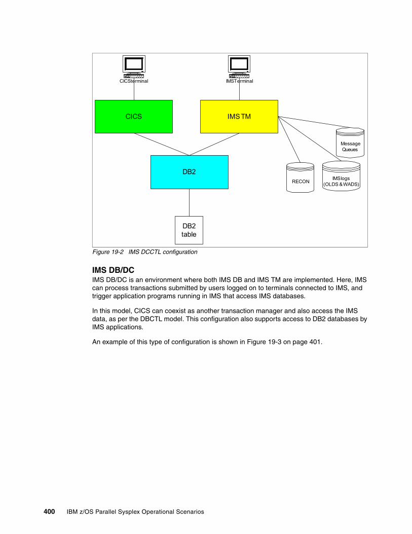
Figure 19-2 IMS DCCTL configuration
IMS DB/DCIMS DB/DC is an environment where both IMS DB and IMS TM are implemented. Here, IMS can process transactions submitted by users logged on to terminals connected to IMS, and trigger application programs running in IMS that access IMS databases.
In this model, CICS can coexist as another transaction manager and also access the IMS data, as per the DBCTL model. This configuration also supports access to DB2 databases by IMS applications.
An example of this type of configuration is shown in Figure 19-3 on page 401.
RECON
CICS
IMS logs(OLDS & WADS)
CICS terminal
IMS TM
IMS Terminal
DB2
DB2table
MessageQueues
400 IBM z/OS Parallel Sysplex Operational Scenarios
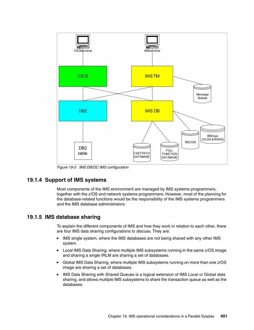
Figure 19-3 IMS DB/DC IMS configuration
19.1.4 Support of IMS systems
Most components of the IMS environment are managed by IMS systems programmers, together with the z/OS and network systems programmers. However, most of the planning for the database-related functions would be the responsibility of the IMS systems programmers and the IMS database administrators.
19.1.5 IMS database sharing
To explain the different components of IMS and how they work in relation to each other, there are four IMS data sharing configurations to discuss. They are:
� IMS single system, where the IMS databases are not being shared with any other IMS system.
� Local IMS Data Sharing, where multiple IMS subsystems running in the same z/OS image and sharing a single IRLM are sharing a set of databases.
� Global IMS Data Sharing, where multiple IMS subsystems running on more than one z/OS image are sharing a set of databases.
� IMS Data Sharing with Shared Queues is a logical extension of IMS Local or Global data sharing, and allows multiple IMS subsystems to share the transaction queue as well as the databases.
IMS DB
FULLFUNCTIONDATABASE
RECON
FAST PATHDATABASE
CICS
IMS logs(OLDS & WADS)
CICS terminal
DB2
DB2table
IMS TM
IMS terminal
MessageQueues
Chapter 19. IMS operational considerations in a Parallel Sysplex 401
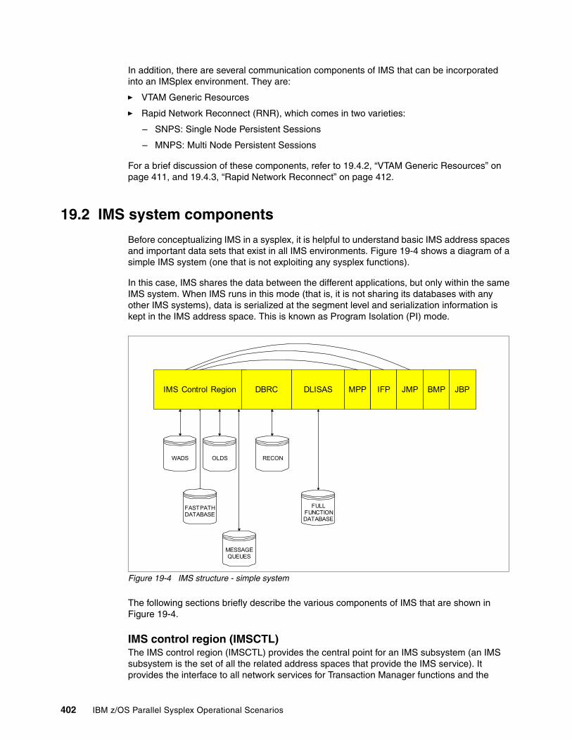
In addition, there are several communication components of IMS that can be incorporated into an IMSplex environment. They are:
� VTAM Generic Resources
� Rapid Network Reconnect (RNR), which comes in two varieties:
– SNPS: Single Node Persistent Sessions
– MNPS: Multi Node Persistent Sessions
For a brief discussion of these components, refer to 19.4.2, “VTAM Generic Resources” on page 411, and 19.4.3, “Rapid Network Reconnect” on page 412.
19.2 IMS system components
Before conceptualizing IMS in a sysplex, it is helpful to understand basic IMS address spaces and important data sets that exist in all IMS environments. Figure 19-4 shows a diagram of a simple IMS system (one that is not exploiting any sysplex functions).
In this case, IMS shares the data between the different applications, but only within the same IMS system. When IMS runs in this mode (that is, it is not sharing its databases with any other IMS systems), data is serialized at the segment level and serialization information is kept in the IMS address space. This is known as Program Isolation (PI) mode.
Figure 19-4 IMS structure - simple system
The following sections briefly describe the various components of IMS that are shown in Figure 19-4.
IMS control region (IMSCTL)The IMS control region (IMSCTL) provides the central point for an IMS subsystem (an IMS subsystem is the set of all the related address spaces that provide the IMS service). It provides the interface to all network services for Transaction Manager functions and the
IMS Control Region DBRC DLISAS MPP IFP JMP JBPBMP
MESSAGEQUEUES
FULLFUNCTIONDATABASE
RECON
FAST PATHDATABASE
OLDSWADS
402 IBM z/OS Parallel Sysplex Operational Scenarios
interface to z/OS for controlling the operation of the IMS subsystem. It also controls and dispatches the application programs running in the various dependent regions.
The control region provides all logging, restart, and recovery functions for the IMS subsystems. The terminals, message queues, and logs are all attached to this region. If Fast Path is used, the Fast Path database data sets are also allocated by the control region address space.
DLISAS (IMSDLI)The DLI Separate Address Space (DLISAS) has all the full function IMS database data sets allocated to it, and it handles most of the data set access functions. It contains some of the control blocks associated with database access and the database buffers used for accessing the “full function” databases. Although it is not required to use the DLISAS address space, its use is recommended. If you specify that you wish to use DLISAS, this address space is automatically started when IMS is started.
DBRC (IMSDBRC) The DataBase Recovery and Control (DBRC) address space contains the code for the DBRC component of IMS. It processes all access to the DBRC recovery control data sets (RECON). It also performs all generation of batch jobs for DBRC; for example, for archiving the online IMS log. All IMS control regions have a corresponding DBRC address space because it is needed, at a minimum, for managing the IMS logs. This address space is automatically started when IMS is started.
Message Processing Regions (MPR)An IMS Message Processing Program (MPP) runs in a Message Processing Region (MPR) and is used to run applications that process messages input to the IMS Transaction Manager component (that is, online programs). The MPRs are usually started by issuing the IMS command /STA REG xxx.
Integrated Fast Path (IFP) regionsIntegrated Fast Path regions also run application programs to process messages for transactions, but in this case it is transactions that have been defined as Fast Path transactions. The applications are broadly similar to the programs that run in an MPR. Like MPRs, the IFP regions are started by the IMS control region as a result of an IMS command. The difference with IFP regions is in the way IMS loads and dispatches the application program, and handles the transaction messages.
Batch Message Processing (BMP) regionUnlike the other types of application-dependent regions, Batch Message Processing regions are not started by the IMS control region, but rather by submitting a batch job. The batch job then connects to an IMS control region identified in the execution parameters. BMPs do not normally process online transactions, but are designed for larger bulk processing of data.
Java Message Processing (JMP) regionA Java Message Processing region is similar to an MPP, except that it is used for Java programs.
Java Batch Processing (JBP) regionsA Java Batch Processing region is similar to a BMP, except that it is used for batch Java programs.
Chapter 19. IMS operational considerations in a Parallel Sysplex 403
RECON data setsThe Recovery Control (RECON) data sets are a set of three VSAM files used by DBRC to hold all the IMS system and database recovery information. Two of these are used at any one time, with the third one available as a spare. For more information about this topic, refer to IMS Database Recovery Control (DBRC) Guide and Reference Version 9, SC18-7818.
OLDS data setsAll IMS log records, database update information, and other system-related information are written to the Online Log Data Sets (OLDS) to enable any database or IMS system recovery. In addition, the OLDS can be post-processed for debugging or accounting purposes.
WADS data setsThe Write Ahead Data Sets (WADS) are also used for logging, and are designed for extremely fast writes using a very small blocksize of 2 K or 4 K. WADS are used for events that cannot wait for partially filled OLDS buffers to be written out. For example, when an IMS transaction completes, the log data must be externalized to ensure any updates are recoverable. If the OLDS buffer is only partially full, it is written to the WADS to avoid writing partial OLDS buffers to the OLDS data set.
On high volume systems, these data sets are critical to performance.
Message queuesAll messages and transactions that come into IMS are placed on the IMS message queue, and are then scheduled to be processed by an online dependant region (for example, an MPR). In a non-sysplex environment, the message queue is actually kept in storage buffers in the IMS control region. In a sysplex environment, you have the option to place the message queue in the Coupling Facility. This is known as IMS Shared Queues.
19.2.1 Terminology
This section defines terminology used later in this chapter.
IMSplexAn IMSplex is one or more IMS subsystems that work together as a unit. Typically (but not always), these address spaces:
� Share either databases or resources or message queues (or a combination of these)� Run in a z/OS Parallel Sysplex environment� Include an IMS Common Service Layer
The address spaces that can participate in the IMSplex are:
� Control region address spaces� IMS manager address spaces (Operations Manager, Resource Manager, Structured Call
Interface)� IMS server address spaces (Common Queue Server (CQS))
An IMSplex allows you to manage multiple IMS systems as though they were one system (a single-system perspective). An IMSplex can exist in a non-sysplex environment, or it can consist of multiple IMS subsystems (in data or queue sharing groups) in a sysplex environment.
404 IBM z/OS Parallel Sysplex Operational Scenarios
IMS data sharingIt is possible for any IMS control region or batch job running in a z/OS system to share access to a set of IMS databases. This requires the use of a separate feature, the Internal Resource Lock Manager (IRLM), to manage the IMS locks on the database (instead of using Program Isolation (PI), as would be used in a single-IMS-subsystem environment).
This type of database sharing is also known as “block-level data sharing”. In block-level data sharing, IMS locks the databases for the application at the block level. By comparison, PI mode locking is done at the segment level; a block will typically contain a number of segments. Because of this coarser level of locking, there is an increased risk of deadlocks and contention between tasks for database records.
Shared queuesIMS provides the option for multiple IMS systems in a sysplex to share a single set of message queues. The set of systems that share the message queue is known as an IMS Queue Sharing Group.
Common Service LayerThe IMS Common Service Layer (CSL) is a collection of IMS manager address spaces that provide the infrastructure needed for IMS systems management tasks. The CSL address spaces include the Operations Manager (OM), the Resource Manager (RM), and the Structured Call Interface (SCI).
Full Function databasesFull Function databases (otherwise known as IMS databases, DL/I databases, or DL/1 databases) provide a hierarchically-structured database that can be accessed directly, sequentially, or by any other predefined method based on a predefined index.
Traditionally, these data bases were limited to 4 GB or 8 GB in size, but they can now be made much larger by exploiting the High Availability Large Databases (HALDB) function available since IMS Version 7.
These physical databases are based on two different access methods, VSAM or OSAM.
VSAM databasesVirtual Sequential Access Method (VSAM) is used by many IMS and non-IMS applications, and comes in two varieties:
� Entry Sequenced Data Sets (ESDS) for the primary data sets
� Key Sequenced Data Sets (KSDS) for index databases
These data sets are defined using the IDCAMS utility program.
OSAM databasesThe Overflow Sequential Access Method (OSAM) is unique to IMS. It is delivered as part of the IMS product. It consists of a series of channel programs that IMS executes to use the standard operating system channel I/O interface. The data sets are defined using JCL statements. As far as the operating system is concerned, an OSAM data set looks like a physical sequential data set (DSORG=PS).
Chapter 19. IMS operational considerations in a Parallel Sysplex 405
Fast Path databasesFast Path databases were originally available only as part of a separately priced, optional feature of IMS. This resulted in the documentation and code being separate from that for the Full Function (FF) databases. There are two types of Fast Path databases:
� Data Entry Databases (DEDBs)
� Main Storage Databases (MSDBs)
DEDBsThe Data Entry Database (DEDB) was designed to support particularly intensive IMS database requirements, primarily in the banking industry, for larger databases, high transaction workloads, improved availability, and reduced I/O.
MSDBsThe Fast Path database access method, Main Storage Database (MSDB), has functionality that has been superseded by the Virtual Storage Option (VSO) of the DEDB, so it is not described in this book, and you are advised not to use it.
19.3 Introduction to IMS in a sysplex
This section describes the components of IMS and how they make up an IMSplex.
19.3.1 Local IMS data sharing
As discussed in 19.1.5, “IMS database sharing” on page 401, IMS supports two ways to share databases across IMS subsystems. Both of these are referred to as Block Level Data Sharing, because the data is shared between the IMS systems at the block level. When two or more IMS subsystems in the same z/OS system access the same database, this is known as local IMS data sharing. It uses the IRLM address space to maintain tables of the locks within IRLM.
An example of this can be found in Figure 19-5 on page 407, which shows a two-way IMSplex running within a single system sharing the IRLM address space as well as the RECON and databases. Note that each system still has its own message queues.
406 IBM z/OS Parallel Sysplex Operational Scenarios
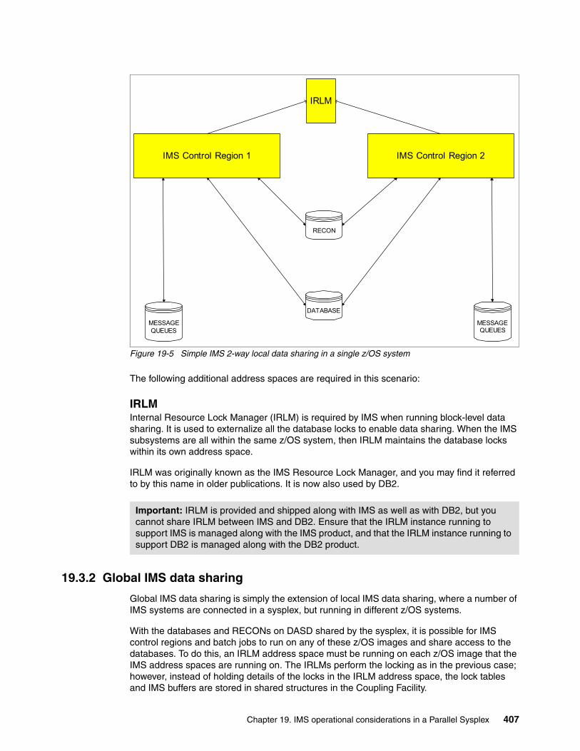
Figure 19-5 Simple IMS 2-way local data sharing in a single z/OS system
The following additional address spaces are required in this scenario:
IRLMInternal Resource Lock Manager (IRLM) is required by IMS when running block-level data sharing. It is used to externalize all the database locks to enable data sharing. When the IMS subsystems are all within the same z/OS system, then IRLM maintains the database locks within its own address space.
IRLM was originally known as the IMS Resource Lock Manager, and you may find it referred to by this name in older publications. It is now also used by DB2.
19.3.2 Global IMS data sharing
Global IMS data sharing is simply the extension of local IMS data sharing, where a number of IMS systems are connected in a sysplex, but running in different z/OS systems.
With the databases and RECONs on DASD shared by the sysplex, it is possible for IMS control regions and batch jobs to run on any of these z/OS images and share access to the databases. To do this, an IRLM address space must be running on each z/OS image that the IMS address spaces are running on. The IRLMs perform the locking as in the previous case; however, instead of holding details of the locks in the IRLM address space, the lock tables and IMS buffers are stored in shared structures in the Coupling Facility.
Important: IRLM is provided and shipped along with IMS as well as with DB2, but you cannot share IRLM between IMS and DB2. Ensure that the IRLM instance running to support IMS is managed along with the IMS product, and that the IRLM instance running to support DB2 is managed along with the DB2 product.
IMS Control Region 1 IMS Control Region 2
IRLM
MESSAGEQUEUES
MESSAGEQUEUES
RECON
DATABASE
Chapter 19. IMS operational considerations in a Parallel Sysplex 407
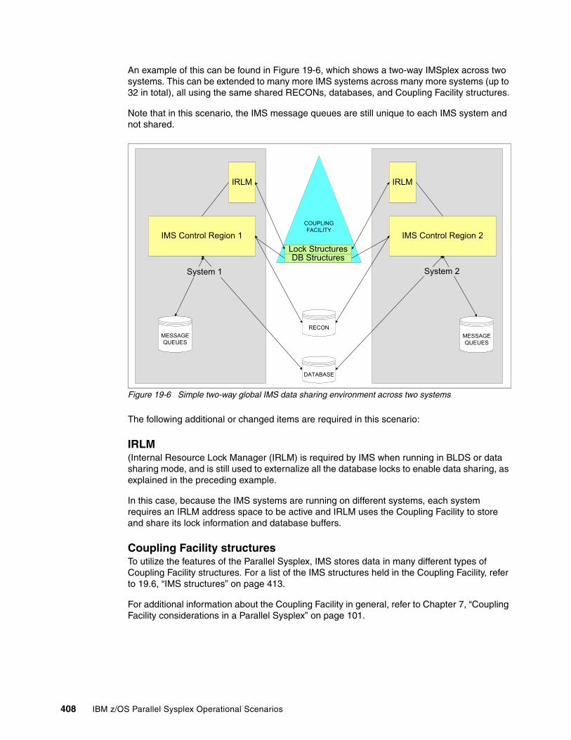
An example of this can be found in Figure 19-6, which shows a two-way IMSplex across two systems. This can be extended to many more IMS systems across many more systems (up to 32 in total), all using the same shared RECONs, databases, and Coupling Facility structures.
Note that in this scenario, the IMS message queues are still unique to each IMS system and not shared.
Figure 19-6 Simple two-way global IMS data sharing environment across two systems
The following additional or changed items are required in this scenario:
IRLM(Internal Resource Lock Manager (IRLM) is required by IMS when running in BLDS or data sharing mode, and is still used to externalize all the database locks to enable data sharing, as explained in the preceding example.
In this case, because the IMS systems are running on different systems, each system requires an IRLM address space to be active and IRLM uses the Coupling Facility to store and share its lock information and database buffers.
Coupling Facility structuresTo utilize the features of the Parallel Sysplex, IMS stores data in many different types of Coupling Facility structures. For a list of the IMS structures held in the Coupling Facility, refer to 19.6, “IMS structures” on page 413.
For additional information about the Coupling Facility in general, refer to Chapter 7, “Coupling Facility considerations in a Parallel Sysplex” on page 101.
IMS Control Region 1 IMS Control Region 2
IRLM IRLM
COUPLINGFACILITY
DB StructuresLock Structures
RECON
DATABASE
MESSAGEQUEUES
MESSAGEQUEUES
System 1 System 2
408 IBM z/OS Parallel Sysplex Operational Scenarios
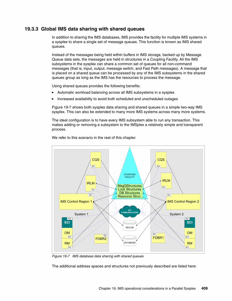
19.3.3 Global IMS data sharing with shared queues
In addition to sharing the IMS databases, IMS provides the facility for multiple IMS systems in a sysplex to share a single set of message queues. This function is known as IMS shared queues.
Instead of the messages being held within buffers in IMS storage, backed up by Message Queue data sets, the messages are held in structures in a Coupling Facility. All the IMS subsystems in the sysplex can share a common set of queues for all non-command messages (that is, input, output, message switch, and Fast Path messages). A message that is placed on a shared queue can be processed by any of the IMS subsystems in the shared queues group as long as the IMS has the resources to process the message.
Using shared queues provides the following benefits:
� Automatic workload balancing across all IMS subsystems in a sysplex
� Increased availability to avoid both scheduled and unscheduled outages
Figure 19-7 shows both sysplex data sharing and shared queues in a simple two-way IMS sysplex. This can also be extended to many more IMS systems across many more systems.
The ideal configuration is to have every IMS subsystem able to run any transaction. This makes adding or removing a subsystem to the IMSplex a relatively simple and transparent process.
We refer to this scenario in the rest of this chapter.
Figure 19-7 IMS database data sharing with shared queues
The additional address spaces and structures not previously described are listed here:
System 2System 1
IMS Control Region 1 IMS Control Region 2
IRLMIRLM
COUPLINGFACILITY
DB Structures
CQS CQS
MsgQStructures
Resource Struc.SCI
SCI
SCI SCI
SCI
SCI
SCI
OM
RM
SCI
SCI
SCI
SCI
OM
RM
SCI
SCI
SCI
FDBR1SCI
FDBR2SCI
Lock Structures
RECON
DATABASE
SCI COMMUNICATIONS
Chapter 19. IMS operational considerations in a Parallel Sysplex 409

Common Queue ServerThe Common Queue Server (CQS) is a generalized server that manages data objects in a Coupling Facility on behalf of multiple clients. It is used by:
� IMS Shared Queues, to provide access to the IMS shared queue structures, which replace the IMS messages queues in the IMS control region storage and the message queue data sets on DASD in a non-shared queues environment
� The Resource Manager address space, to access the resource manager structure
If using shared queues, this address space is automatically started when IMS is started.
To shut down IMS in this environment, it is recommended that you enter /CHECKPOINT FREEZE. CQS may automatically shutdown, based on the status of the /CQS command, as mentioned in 19.11.4, “CQS shutdown” on page 452. If the DUMPQ or PURGE option is used, IMS does not dump the message queues during shutdown.
CQS automatically registers with the Automatic Restart Manager; see Chapter 6, “Automatic Restart Manager” on page 83 for more information. It does not have to be manually restarted after a CQS failure. CQS does not have to be restarted after an IMS failure because CQS and IMS are known as separate subsystems to ARM. If CQS is not available, IMS will not shut down using /CHECKPOINT FREEZE but only with the z/OS MODIFY command.
Recovery of the IMS shared queue structures is handled by the master CQS. This involves repopulating the structure using the CQS Structure Recovery Data sets (SRDS), and then applying updates using the message queue log stream. In the case of a structure not recovering, then forcing the structure may be required. If this is done, it is similar to an IMS cold start and the IMS system programmers should be involved.
More information can be found in the IMS manuals and other IBM Redbooks publications about the IMS sysplex.
Structured Call InterfaceThe Structured Call Interface (SCI) address space provides for standardized intra-IMSplex communications between members of an IMSplex. It also provides security authorization for IMSplex membership, and SCI services to registered members.
The structured call interface services are used by SCI clients to register and deregister as members of the IMSplex and to communicate with other members.
When running in an IMSplex environment, one SCI address space is required on each z/OS image with IMS sysplex members, and it needs to be started prior to IMS starting.
Resource ManagerThe Resource Manager (RM) address space maintains global resource information for clients using a Resource structure in the Coupling Facility
It can contain IMSplex global and local member information, resource names and types, terminal and user status, global process status, and resource management services. It also handles sysplex terminal management and global online change.
One or more RM address spaces are required per IMSplex in IMS V8. IMS V9 allows for zero RMs in the IMSplex.
Warning: If CQS abnormally ends, it needs to be restarted as soon as possible to avoid having to cold start IMS if two structure checkpoints should occur before this is done.
410 IBM z/OS Parallel Sysplex Operational Scenarios
Operations ManagerThe Operations Manager (OM) address space provides an API allowing single point of command entry into IMSplex. It will become the focal point for operations management and automation. Command responses from multiple IMS systems are consolidated.
One or more OM address spaces are required per IMSplex.
Fast Database RecoveryFast Database Recovery (FDBR) is an optional function of IMS. It is designed to quickly release locks held by an IMS subsystem if that subsystem fails. It would normally run on an alternate z/OS system within the sysplex, in case the system IMS is running on abends. For a detailed description of Fast Database Recovery (which was made available along with IMS Version 6), refer to IMS/ESA Version 6 Guide, SG24-2228.
19.4 IMS communication components of an IMSplex
The previous sections of this chapter refer to all the address spaces and components specific to both data sharing and message queue sharing. However, there are several other components of IMS that can also have an impact within an IMSplex, as discussed here.
19.4.1 IMS Connect
IMS Connect is used to communicate between TCP/IP clients and IMS.
Prior to IMS Version 9, IMS Connect was available as a separately-orderable product. It may also be referred to by its original name, IMS TCP/IP OTMA Connector (ITOC). Since IMS Version 9, IMS Connect is delivered as part of IMS.
Although IMS Connect does not impact how an IMSplex functions, and therefore was not included in the previous figures, it has been included here because of its growing importance in customer IMS configurations.
IMS Connect runs as a separate address space on one or more of the systems within the sysplex. It listens for incoming TCP requests on predefined TCP/IP ports. Further information about IMS Connect can be found in the publication IMS Connect Guide and Reference, Version 9, SC18-9287.
19.4.2 VTAM Generic Resources
VTAM Generic Resources (VGR) is a service provided by VTAM that allows multiple instances of a server application (such as IMS) to be accessed using a single VTAM resource name. This minimizes the information that the user needs to know to logon to IMS. Each IMS in the sharing group joins a Generic Resource Group, and the user simply logs on using the VTAM application name for this sharing group. VTAM then selects which IMS in the group the user will be logged on to, transparently to the user. In addition to making the process simpler for the user, this also assists with workload balancing across the IMSplex and masks the unavailability of a single IMS subsystem from the user.
The information about which members are in the Generic Resource Group, and their status, is stored in a structure in the Coupling Facility. For more information, refer to Chapter 16, “Network considerations in a Parallel Sysplex” on page 323.
Chapter 19. IMS operational considerations in a Parallel Sysplex 411
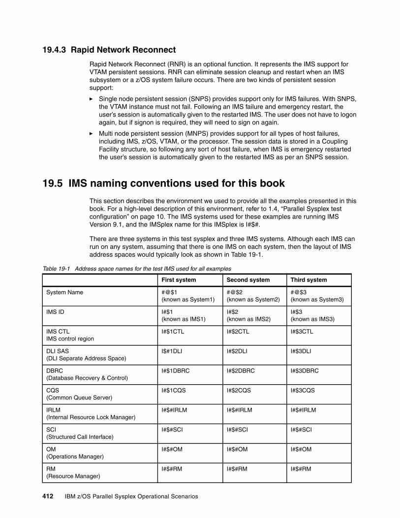
19.4.3 Rapid Network Reconnect
Rapid Network Reconnect (RNR) is an optional function. It represents the IMS support for VTAM persistent sessions. RNR can eliminate session cleanup and restart when an IMS subsystem or a z/OS system failure occurs. There are two kinds of persistent session support:
� Single node persistent session (SNPS) provides support only for IMS failures. With SNPS, the VTAM instance must not fail. Following an IMS failure and emergency restart, the user’s session is automatically given to the restarted IMS. The user does not have to logon again, but if signon is required, they will need to sign on again.
� Multi node persistent session (MNPS) provides support for all types of host failures, including IMS, z/OS, VTAM, or the processor. The session data is stored in a Coupling Facility structure, so following any sort of host failure, when IMS is emergency restarted the user’s session is automatically given to the restarted IMS as per an SNPS session.
19.5 IMS naming conventions used for this book
This section describes the environment we used to provide all the examples presented in this book. For a high-level description of this environment, refer to 1.4, “Parallel Sysplex test configuration” on page 10. The IMS systems used for these examples are running IMS Version 9.1, and the IMSplex name for this IMSplex is I#$#.
There are three systems in this test sysplex and three IMS systems. Although each IMS can run on any system, assuming that there is one IMS on each system, then the layout of IMS address spaces would typically look as shown in Table 19-1.
Table 19-1 Address space names for the test IMS used for all examples
First system Second system Third system
System Name #@$1(known as System1)
#@$2(known as System2)
#@$3(known as System3)
IMS ID I#$1(known as IMS1)
I#$2(known as IMS2)
I#$3(known as IMS3)
IMS CTLIMS control region
I#$1CTL I#$2CTL I#$3CTL
DLI SAS(DLI Separate Address Space)
I$#1DLI I#$2DLI I#$3DLI
DBRC(Database Recovery & Control)
I#$1DBRC I#$2DBRC I#$3DBRC
CQS(Common Queue Server)
I#$1CQS I#$2CQS I#$3CQS
IRLM(Internal Resource Lock Manager)
I#$#IRLM I#$#IRLM I#$#IRLM
SCI(Structured Call Interface)
I#$#SCI I#$#SCI I#$#SCI
OM(Operations Manager)
I#$#OM I#$#OM I#$#OM
RM(Resource Manager)
I#$#RM I#$#RM I#$#RM
412 IBM z/OS Parallel Sysplex Operational Scenarios
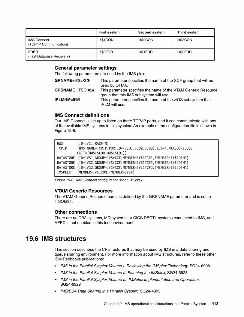
General parameter settingsThe following parameters are used by the IMS plex:
GRNAME=I#$#XCF This parameter specifies the name of the XCF group that will be used by OTMA.
GRSNAME=ITSOI#$# This parameter specifies the name of the VTAM Generic Resource group that this IMS subsystem will use.
IRLMNM=IR#I This parameter specifies the name of the z/OS subsystem that IRLM will use.
IMS Connect definitionsOur IMS Connect is set up to listen on three TCP/IP ports, and it can communicate with any of the available IMS systems in this sysplex. An example of the configuration file is shown in Figure 19-8.
Figure 19-8 IMS Connect configuration for an IMSplex
VTAM Generic ResourcesThe VTAM Generic Resource name is defined by the GRSNAME parameter and is set to ITSOI#$#.
Other connectionsThere are no DB2 systems, MQ systems, or CICS DBCTL systems connected to IMS, and APPC is not enabled in this test environment.
19.6 IMS structures
This section describes the CF structures that may be used by IMS in a data sharing and queue sharing environment. For more information about IMS structures, refer to these other IBM Redbooks publications:
� IMS in the Parallel Sysplex Volume I: Reviewing the IMSplex Technology, SG24-6908
� IMS in the Parallel Sysplex Volume II: Planning the IMSplex, SG24-6928
� IMS in the Parallel Sysplex Volume III: IMSplex Implementation and Operations, SG24-6929
� IMS/ESA Data Sharing in a Parallel Sysplex, SG24-4303
IMS Connect(TCP/IP Communication)
I#$1CON I#$2CON I#$3CON
FDBR(Fast Database Recovery)
I#$3FDR I#$1FDR I#$2FDR
First system Second system Third system
HWS (ID=I#$1,RACF=N) TCPIP (HOSTNAME=TCPIP,PORTID=(7101,7102,7103),ECB=Y,MAXSOC=1000, EXIT=(HWSCSLO0,HWSCSLO1)) DATASTORE (ID=I#$1,GROUP=I#$#XCF,MEMBER=I#$1TCP1,TMEMBER=I#$1OTMA) DATASTORE (ID=I#$2,GROUP=I#$#XCF,MEMBER=I#$1TCP2,TMEMBER=I#$2OTMA) DATASTORE (ID=I#$3,GROUP=I#$#XCF,MEMBER=I#$1TCP3,TMEMBER=I#$3OTMA) IMSPLEX (MEMBER=I#$1CON,TMEMBER=I#$#)
Chapter 19. IMS operational considerations in a Parallel Sysplex 413
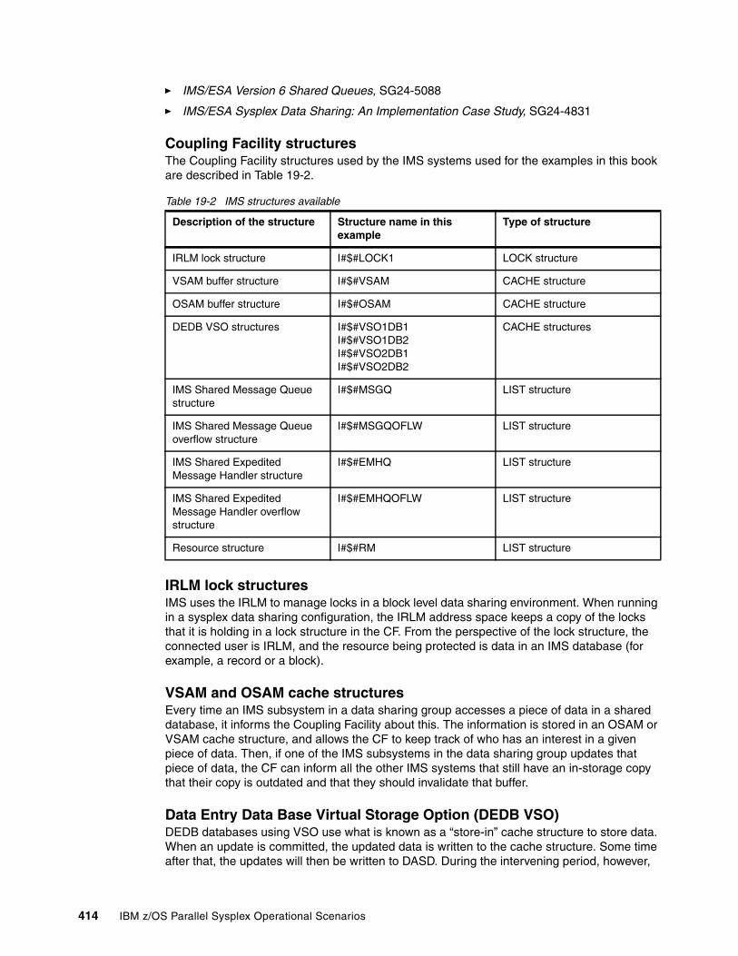
� IMS/ESA Version 6 Shared Queues, SG24-5088
� IMS/ESA Sysplex Data Sharing: An Implementation Case Study, SG24-4831
Coupling Facility structuresThe Coupling Facility structures used by the IMS systems used for the examples in this book are described in Table 19-2.
Table 19-2 IMS structures available
IRLM lock structuresIMS uses the IRLM to manage locks in a block level data sharing environment. When running in a sysplex data sharing configuration, the IRLM address space keeps a copy of the locks that it is holding in a lock structure in the CF. From the perspective of the lock structure, the connected user is IRLM, and the resource being protected is data in an IMS database (for example, a record or a block).
VSAM and OSAM cache structuresEvery time an IMS subsystem in a data sharing group accesses a piece of data in a shared database, it informs the Coupling Facility about this. The information is stored in an OSAM or VSAM cache structure, and allows the CF to keep track of who has an interest in a given piece of data. Then, if one of the IMS subsystems in the data sharing group updates that piece of data, the CF can inform all the other IMS systems that still have an in-storage copy that their copy is outdated and that they should invalidate that buffer.
Data Entry Data Base Virtual Storage Option (DEDB VSO)DEDB databases using VSO use what is known as a “store-in” cache structure to store data. When an update is committed, the updated data is written to the cache structure. Some time after that, the updates will then be written to DASD. During the intervening period, however,
Description of the structure Structure name in this example
Type of structure
IRLM lock structure I#$#LOCK1 LOCK structure
VSAM buffer structure I#$#VSAM CACHE structure
OSAM buffer structure I#$#OSAM CACHE structure
DEDB VSO structures I#$#VSO1DB1I#$#VSO1DB2I#$#VSO2DB1I#$#VSO2DB2
CACHE structures
IMS Shared Message Queue structure
I#$#MSGQ LIST structure
IMS Shared Message Queue overflow structure
I#$#MSGQOFLW LIST structure
IMS Shared Expedited Message Handler structure
I#$#EMHQ LIST structure
IMS Shared Expedited Message Handler overflow structure
I#$#EMHQOFLW LIST structure
Resource structure I#$#RM LIST structure
414 IBM z/OS Parallel Sysplex Operational Scenarios
the updated data is only available in the cache structure. If that structure is lost for some reason, the updates must be recovered by reading back through the IMS logs.
Message Queue (MSGQ) structureThe Message Queue structure is a list structure that contains the IMS shared message queues for full function IMS transactions.
Expedited Message Handler Queue (EMHQ) structureThe Expedited Message Handler Queue structure is a list structure that contains the IMS expedited message handler queues for fast path IMS transactions.
With IMS Version 8 and earlier, this structure is required whether or not Fast Path is implemented. From IMS version 9, this structure is optional (and is not used) if Fast Path is not required.
MSGQ and EMHQ overflow structuresThe shared queue overflow structures are both list structures that contain selected messages from the shared queues when the MSGQ or EMHQ primary structures reach an installation-specified overflow threshold. The overflow structures are optional.
Message Queue and EMHQ log streamsThe Message Queue and EMHQ log streams are shared System Logger log streams that contain all CQS log records from all CQSs in the shared queues group. This log stream is important for recovery of shared queues, if necessary. Each shared queue structure pair has an associated log stream.
Resource structureThe Resource structure is a CF list structure that contains information about uniquely-named resources that are managed by the resource manager address space. This structures takes on a greater role with the introduction of Dynamic Resource Definition in IMS Version 10.
Checkpoint data setsA local data set that contains CQS system checkpoint information. There is one set of these data sets per CQS address space.
Structure Recovery Data SetsThe Structure Recovery Data Sets (SRDS) are data sets that contain structure checkpoint information for shared queues on a structure pair. All CQS address spaces in the queue sharing group share the one set of SRDS data sets. Each structure pair has two associated SRDSs.
19.6.1 IMS structure duplexing
As you can see, the CF structures contain information that is critical to the successful functioning of the IMSplex. To ensure that IMS can deliver the expected levels of availability, therefore, it is vital that all the structure contents can be quickly recovered in case of a failure of the CF containing those structures.
One way to address this requirement is to maintain duplex copies of the structures, so that if one CF fails, all the structure contents are immediately available in the other CF. In this case, the system automatically swaps to the duplexed structure with minimal interruption. There are different types of structure duplexing available to IMS for its various structures.
Chapter 19. IMS operational considerations in a Parallel Sysplex 415
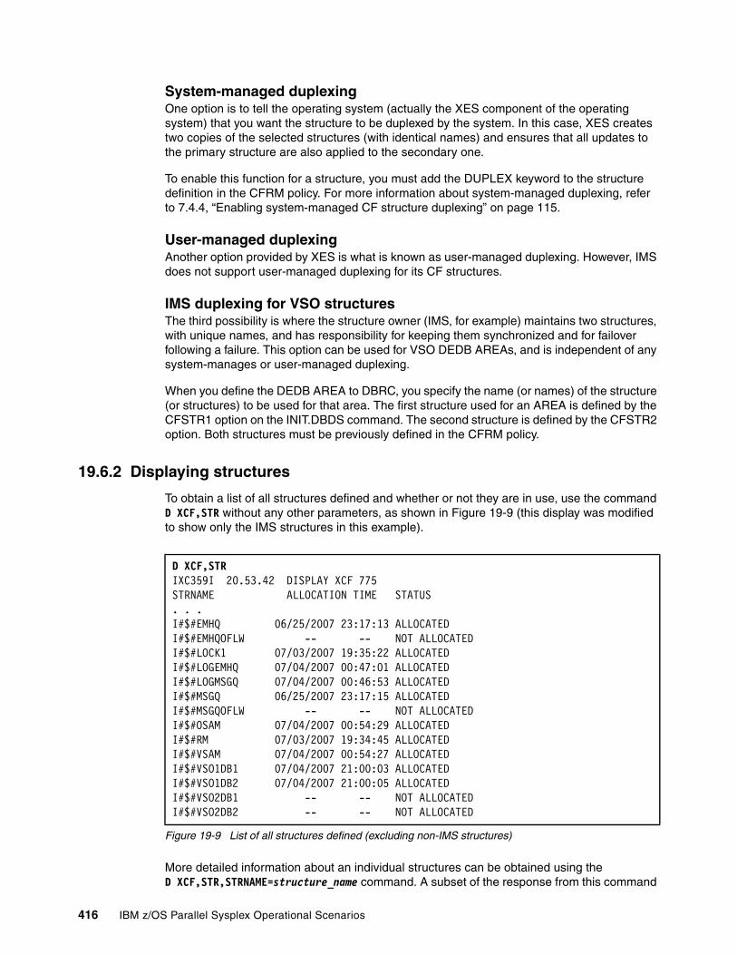
System-managed duplexingOne option is to tell the operating system (actually the XES component of the operating system) that you want the structure to be duplexed by the system. In this case, XES creates two copies of the selected structures (with identical names) and ensures that all updates to the primary structure are also applied to the secondary one.
To enable this function for a structure, you must add the DUPLEX keyword to the structure definition in the CFRM policy. For more information about system-managed duplexing, refer to 7.4.4, “Enabling system-managed CF structure duplexing” on page 115.
User-managed duplexingAnother option provided by XES is what is known as user-managed duplexing. However, IMS does not support user-managed duplexing for its CF structures.
IMS duplexing for VSO structuresThe third possibility is where the structure owner (IMS, for example) maintains two structures, with unique names, and has responsibility for keeping them synchronized and for failover following a failure. This option can be used for VSO DEDB AREAs, and is independent of any system-manages or user-managed duplexing.
When you define the DEDB AREA to DBRC, you specify the name (or names) of the structure (or structures) to be used for that area. The first structure used for an AREA is defined by the CFSTR1 option on the INIT.DBDS command. The second structure is defined by the CFSTR2 option. Both structures must be previously defined in the CFRM policy.
19.6.2 Displaying structures
To obtain a list of all structures defined and whether or not they are in use, use the command D XCF,STR without any other parameters, as shown in Figure 19-9 (this display was modified to show only the IMS structures in this example).
Figure 19-9 List of all structures defined (excluding non-IMS structures)
More detailed information about an individual structures can be obtained using the D XCF,STR,STRNAME=structure_name command. A subset of the response from this command
D XCF,STR IXC359I 20.53.42 DISPLAY XCF 775 STRNAME ALLOCATION TIME STATUS . . .I#$#EMHQ 06/25/2007 23:17:13 ALLOCATED I#$#EMHQOFLW -- -- NOT ALLOCATED I#$#LOCK1 07/03/2007 19:35:22 ALLOCATED I#$#LOGEMHQ 07/04/2007 00:47:01 ALLOCATED I#$#LOGMSGQ 07/04/2007 00:46:53 ALLOCATED I#$#MSGQ 06/25/2007 23:17:15 ALLOCATED I#$#MSGQOFLW -- -- NOT ALLOCATED I#$#OSAM 07/04/2007 00:54:29 ALLOCATED I#$#RM 07/03/2007 19:34:45 ALLOCATED I#$#VSAM 07/04/2007 00:54:27 ALLOCATED I#$#VSO1DB1 07/04/2007 21:00:03 ALLOCATEDI#$#VSO1DB2 07/04/2007 21:00:05 ALLOCATEDI#$#VSO2DB1 -- -- NOT ALLOCATEDI#$#VSO2DB2 -- -- NOT ALLOCATED
416 IBM z/OS Parallel Sysplex Operational Scenarios
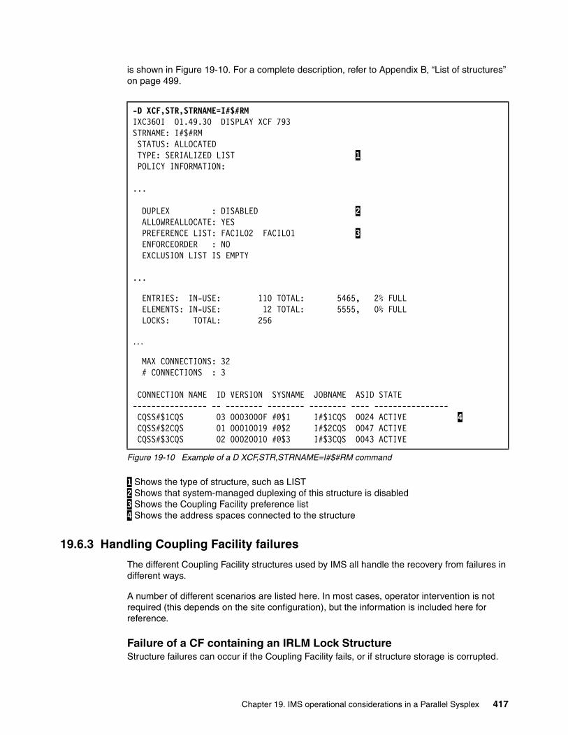
is shown in Figure 19-10. For a complete description, refer to Appendix B, “List of structures” on page 499.
Figure 19-10 Example of a D XCF,STR,STRNAME=I#$#RM command
1 Shows the type of structure, such as LIST 2 Shows that system-managed duplexing of this structure is disabled 3 Shows the Coupling Facility preference list 4 Shows the address spaces connected to the structure
19.6.3 Handling Coupling Facility failures
The different Coupling Facility structures used by IMS all handle the recovery from failures in different ways.
A number of different scenarios are listed here. In most cases, operator intervention is not required (this depends on the site configuration), but the information is included here for reference.
Failure of a CF containing an IRLM Lock Structure Structure failures can occur if the Coupling Facility fails, or if structure storage is corrupted.
-D XCF,STR,STRNAME=I#$#RMIXC360I 01.49.30 DISPLAY XCF 793 STRNAME: I#$#RM STATUS: ALLOCATED TYPE: SERIALIZED LIST 1 POLICY INFORMATION:
...
DUPLEX : DISABLED 2 ALLOWREALLOCATE: YES PREFERENCE LIST: FACIL02 FACIL01 3 ENFORCEORDER : NO EXCLUSION LIST IS EMPTY
...
ENTRIES: IN-USE: 110 TOTAL: 5465, 2% FULL ELEMENTS: IN-USE: 12 TOTAL: 5555, 0% FULL LOCKS: TOTAL: 256
...
MAX CONNECTIONS: 32 # CONNECTIONS : 3 CONNECTION NAME ID VERSION SYSNAME JOBNAME ASID STATE ---------------- -- -------- -------- -------- ---- ---------------- CQSS#$1CQS 03 0003000F #@$1 I#$1CQS 0024 ACTIVE 4 CQSS#$2CQS 01 00010019 #@$2 I#$2CQS 0047 ACTIVE CQSS#$3CQS 02 00020010 #@$3 I#$3CQS 0043 ACTIVE
Chapter 19. IMS operational considerations in a Parallel Sysplex 417
If a loss of the IRLM structures or the Coupling Facility that contain the IRLM structure occurs, then:
� IMS batch data sharing jobs end abnormally with a U3303 abend code on the system with the loss of connectivity. Backout is required for updaters. All the batch data sharing jobs must be restarted later.
� Although the online system continues operating, data sharing quiesces, and transactions making lock requests are suspended until the lock structure is automatically rebuilt. Each IRLM participating in the data sharing group is active in the automatic rebuild of the IRLM lock structure to the alternate CF.
� When the rebuilding is complete, transactions that were suspended have their lock requests processed.
To invoke automated recovery, a second Coupling Facility is required and the CFRM policy must specify an alternate CF in the preference list.
The target CF structure is repopulated with active locks from the IRLMs. Given that IMS and IRLM will rebuild the structure1, using system-managed duplexing for the lock structure will not provide any additional recovery, but it may speed up the recovery.
Failure of a CF containing an OSAM or VSAM cache structure If a CF containing the IMS OSAM or VSAM cache structures fails, then:
� All local OSAM buffers are invalidated if the CF contains an OSAM cache structure. This means that buffers cannot be used and any future request for blocks requires a read from DASD. This impacts performance but not availability.
� All VSAM buffers are invalidated if the CF contains a VSAM cache structure. The process for the VSAM buffer set is the same as for the OSAM buffers.
� The online subsystems continue, but some transactions may get “lock reject” status when receiving an error return code from an operation to the OSAM or VSAM structure. This results in an abend U3303 code or return of status codes BA or BB, depending on how the applications have been coded. After an application receives the error return code, no other programs will begin a new operation to the structure.
� All transactions that would initiate an operation that will result in an access to the structure are placed into a wait. When the structure is rebuilt, they are taken out of this wait state.
� IMS batch data sharing jobs abend, and backout is required for updates. All of the batch data sharing jobs must be restarted later.
All IMS subsystems participate in the rebuild process because the architecture requires this for all connectors during a rebuild. The contents of the buffer pools are not used in this rebuild; the OSAM and VSAM structures are rebuilt but empty. No operator involvement is necessary and the time required for structure rebuild is measured in seconds, rather than minutes.
Integrity of the data in the databases is not compromised, because this is a store-through cache structure. Everything that was in the structure has already been written to DASD.
Fast Path DEDB VSO structure read and write errors Although the following seven situations do not all result in the loss of access to the VSO cache structure, two of them cause IMS to unload the data from the cache.
1 This assumes that only the lock structure was impacted by the failure. If the lock structure and one or more connected IRLMs are impacted, all IRLMs in the data sharing group will abend and need to be restarted.
418 IBM z/OS Parallel Sysplex Operational Scenarios
Read errors from the CF structureIf only one VSO cache structure is defined, then the application is presented with a status code and a DFS2830I message displayed. If two structures are defined for the DEDB VSO area, then the read request is reissued to the second structure.
When four read errors occur with a single structureThe area is unloaded from the structure to DASD by means of an internal /VUNLOAD command, resulting in what is known as “castout” processing. Only changed control intervals are written, and if the control interval with the read error has been modified, an Error Queue Element (EQE) is created. The area is stopped on that IMS, but processing continues from DASD.
When four read errors occur with dual structuresThere are still only three errors allowed. The fourth read error causes a disconnect from the offending structure and a continuation using the second structure. If both structures become unavailable for use, then the area is stopped on that IMS system. For VSO (non-preload), if the control interval is not in the Coupling Facility, it is read from DASD and written to the CF.
Write errors to a single CF structureIf an error occurs writing to the VSO cache structure, the control interval is deleted from the CF structure and written to DASD. If the delete fails, a notification is shipped to the data sharing IMS subsystems to delete the entry:
� If the sharers cannot delete the entry, an EQE is created and propagated to all sharing subsystems. Because shared VSO does not support I/O toleration, this situation is treated as though an I/O error on DASD occurred.
� If the sharing subsystems can delete the entry, the buffer is written to DASD and subsequent access to that control interval is from DASD.
Write errors in a dual CF structureIf multiple structures are defined, and a write request to one of the structures fails, the entry is deleted from the structure by this local IMS or one of the sharing partners. The write is then done to one of the other structures. If one of the writes is successful, then it is considered to be a completed write. If the write fails on both structures, the control interval is deleted by one of the sharing partners in both structures and then written to DASD. The next request for that control interval will be satisfied from DASD.
When four write errors occur with a single structureThe area is unloaded by means of an internal /VUNLOAD command from the CF using castout processing and the area is stopped on the detecting IMS. Only changed control intervals are written and if the control interval with the read error has been modified, an EQE is created. Processing continues from DASD.
When four write errors occur with dual structuresIf the fourth request fails, and multiple structures are defined, IMS disconnects from the structure in error and continues processing with the one structure remaining.
CQS Shared Message Queue structure failuresCQS takes regular snapshots of the content of the shared queue structures to the SRDS data sets. If the CF containing the shared queue structure fails, and the structure is not duplexed, CQS allocates a new structure in an alternate CF (one of the ones listed in the PREFLIST in the CFRM policy). It populates it with the snap shot from the SRDS data set, and applies all the log records from the log stream, bringing the structure back up to date as of the time of the failure.
Chapter 19. IMS operational considerations in a Parallel Sysplex 419
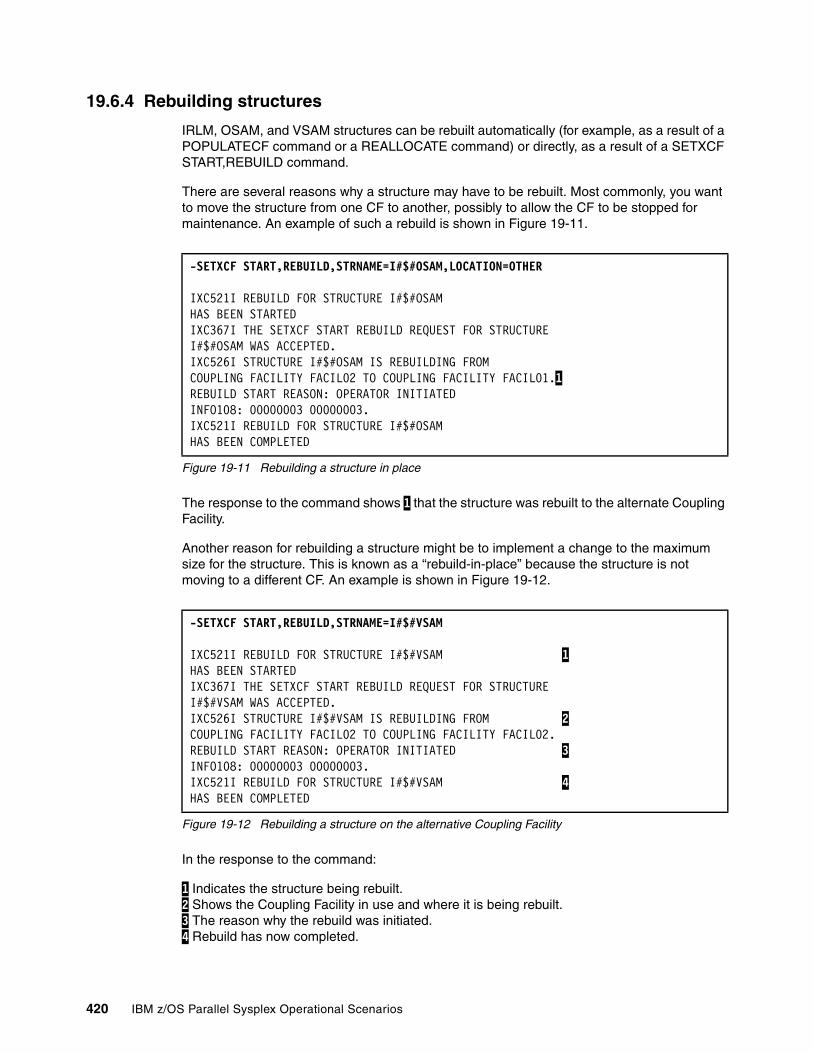
19.6.4 Rebuilding structures
IRLM, OSAM, and VSAM structures can be rebuilt automatically (for example, as a result of a POPULATECF command or a REALLOCATE command) or directly, as a result of a SETXCF START,REBUILD command.
There are several reasons why a structure may have to be rebuilt. Most commonly, you want to move the structure from one CF to another, possibly to allow the CF to be stopped for maintenance. An example of such a rebuild is shown in Figure 19-11.
Figure 19-11 Rebuilding a structure in place
The response to the command shows 1 that the structure was rebuilt to the alternate Coupling Facility.
Another reason for rebuilding a structure might be to implement a change to the maximum size for the structure. This is known as a “rebuild-in-place” because the structure is not moving to a different CF. An example is shown in Figure 19-12.
Figure 19-12 Rebuilding a structure on the alternative Coupling Facility
In the response to the command:
1 Indicates the structure being rebuilt. 2 Shows the Coupling Facility in use and where it is being rebuilt. 3 The reason why the rebuild was initiated. 4 Rebuild has now completed.
-SETXCF START,REBUILD,STRNAME=I#$#OSAM,LOCATION=OTHER
IXC521I REBUILD FOR STRUCTURE I#$#OSAM HAS BEEN STARTED IXC367I THE SETXCF START REBUILD REQUEST FOR STRUCTURE I#$#OSAM WAS ACCEPTED. IXC526I STRUCTURE I#$#OSAM IS REBUILDING FROM COUPLING FACILITY FACIL02 TO COUPLING FACILITY FACIL01.1REBUILD START REASON: OPERATOR INITIATED INFO108: 00000003 00000003. IXC521I REBUILD FOR STRUCTURE I#$#OSAM HAS BEEN COMPLETED
-SETXCF START,REBUILD,STRNAME=I#$#VSAM
IXC521I REBUILD FOR STRUCTURE I#$#VSAM 1HAS BEEN STARTED IXC367I THE SETXCF START REBUILD REQUEST FOR STRUCTURE I#$#VSAM WAS ACCEPTED. IXC526I STRUCTURE I#$#VSAM IS REBUILDING FROM 2COUPLING FACILITY FACIL02 TO COUPLING FACILITY FACIL02. REBUILD START REASON: OPERATOR INITIATED 3INFO108: 00000003 00000003. IXC521I REBUILD FOR STRUCTURE I#$#VSAM 4HAS BEEN COMPLETED
420 IBM z/OS Parallel Sysplex Operational Scenarios
Most structures can be rebuilt without impacting the users of those structures. However, in the case of a rebuild of an IMS OSAM structure, if batch DL/1 jobs using shared OSAM databases were running at the time of the rebuild, those jobs will abend and will need to be restarted. To avoid this, we recommend only rebuilding these structures at a time when no IMS batch DL/1 jobs are running.
19.7 IMS use of Automatic Restart Manager
This section describes the impact of the z/OS facility Automatic Restart Manager (ARM) has on IMS and its various address spaces. It also provides examples showing what will occur in various scenarios.
IMS is able to use the function of ARM, and this section summarizes that from an IMS perspective. Refer to Chapter 6, “Automatic Restart Manager” on page 83 for further details about ARM in general.
IBM provides policy defaults for Automatic Restart Management. You can use these defaults, or you can define your own ARM policy to specify how the various IMS address spaces should be restarted.
19.7.1 Defining ARM policies
The ARM policies define which jobs are to be restarted by ARM, and some detail about how this will occur. For further detail about how to define ARM policies, refer to MVS Setting Up A Sysplex, SA22-7625, under “Automatic Restart Management Parameters for Administrative Data Utility.”
Note the following points:
� The RESTART_ORDER parameter can specify the order in which certain jobs within a group are started.
� The RESTART_GROUP can group a number of different jobs so they always get acted on together.
� The TARGET_SYSTEM can indicate which system you want the tasks restarted on. If nothing is specified, the restart will occur on any appropriate system, optionally dependent on CSA by specifying the FREE_CSA parameter.
19.7.2 ARM and the IMS address spaces
The ARM configuration should be closely coordinated with any automation products to avoid duplicate startup attempts.
Only those jobs or started tasks which register to ARM are eligible to be restarted by ARM. IMS control regions, IRLMs, FDBR, and CQS may do this registration. For control regions, FDBR, and CQS, it is optional. For the IRLM, it always occurs when ARM is active.
IMS dependent regions (MPR, BMP, and IFP), IMS batch jobs (DLI and DBB), IMS utilities, and the online DBRC and DL/I SAS regions do not register to ARM.
There is no need for ARM to restart online DBRC and DLISAS regions, because they are started internally by the control region.
Chapter 19. IMS operational considerations in a Parallel Sysplex 421
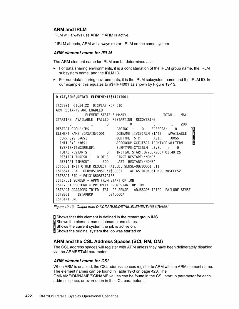
ARM and IRLMIRLM will always use ARM, if ARM is active.
If IRLM abends, ARM will always restart IRLM on the same system.
ARM element name for IRLM
The ARM element name for IRLM can be determined as:
� For data sharing environments, it is a concatenation of the IRLM group name, the IRLM subsystem name, and the IRLM ID.
� For non-data sharing environments, it is the IRLM subsystem name and the IRLM ID. In our example, this equates to #$#IR#I001 as shown by Figure 19-13.
Figure 19-13 Output from D XCF,ARMS,DETAIL,ELEMENT=I#$#IR#I001
1 Shows that this element is defined in the restart group IMS. 2 Shows the element name, jobname and status. 3 Shows the current system the job is active on. 4 Shows the original system the job was started on.
ARM and the CSL Address Spaces (SCI, RM, OM)The CSL address spaces will register with ARM unless they have been deliberately disabled via the ARMRST=N parameter.
ARM element name for CSLWhen ARM is enabled, the CSL address spaces register to ARM with an ARM element name. The element names can be found in Table 19-3 on page 423. The OMNAME/RMNAME/SCINAME values can be found in the CSL startup parameter for each address space, or overridden in the JCL parameters.
D XCF,ARMS,DETAIL,ELEMENT=I#$#IR#I001
IXC392I 01.54.22 DISPLAY XCF 510 ARM RESTARTS ARE ENABLED -------------- ELEMENT STATE SUMMARY -------------- -TOTAL- -MAX- STARTING AVAILABLE FAILED RESTARTING RECOVERING 0 1 0 0 0 1 200 RESTART GROUP:IMS PACING : 0 FREECSA: 0 01ELEMENT NAME :I#$#IR#I001 JOBNAME :I#$#IRLM STATE :AVAILABLE 2 CURR SYS :#@$1 JOBTYPE :STC ASID :0055 3 INIT SYS :#@$1 JESGROUP:XCFJES2A TERMTYPE:ALLTERM 4 EVENTEXIT:DXRRL0F1 ELEMTYPE:SYSIRLM LEVEL : 0 TOTAL RESTARTS : 0 INITIAL START:07/03/2007 01:49:25 RESTART THRESH : 0 OF 3 FIRST RESTART:*NONE* RESTART TIMEOUT: 300 LAST RESTART:*NONE* IST663I INIT OTHER REQUEST FAILED, SENSE=087D0001 511 IST664I REAL OLU=USIBMSC.#@$CCC$1 ALIAS DLU=USIBMSC.#@$CCC$2 IST889I SID = E61318508EB7A1B3 IST1705I SORDER = APPN FROM START OPTION IST1705I SSCPORD = PRIORITY FROM START OPTION IST894I ADJSSCPS TRIED FAILURE SENSE ADJSSCPS TRIED FAILURE SENSE IST895I ISTAPNCP 08400007 IST314I END
422 IBM z/OS Parallel Sysplex Operational Scenarios
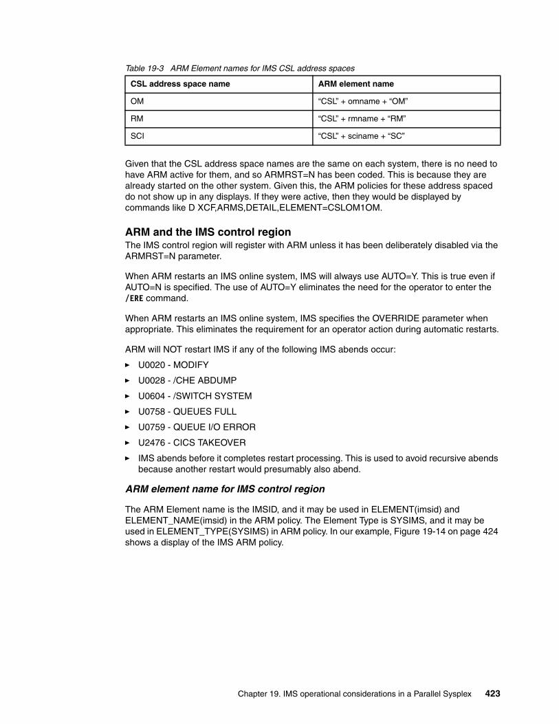
Table 19-3 ARM Element names for IMS CSL address spaces
Given that the CSL address space names are the same on each system, there is no need to have ARM active for them, and so ARMRST=N has been coded. This is because they are already started on the other system. Given this, the ARM policies for these address spaced do not show up in any displays. If they were active, then they would be displayed by commands like D XCF,ARMS,DETAIL,ELEMENT=CSLOM1OM.
ARM and the IMS control regionThe IMS control region will register with ARM unless it has been deliberately disabled via the ARMRST=N parameter.
When ARM restarts an IMS online system, IMS will always use AUTO=Y. This is true even if AUTO=N is specified. The use of AUTO=Y eliminates the need for the operator to enter the /ERE command.
When ARM restarts an IMS online system, IMS specifies the OVERRIDE parameter when appropriate. This eliminates the requirement for an operator action during automatic restarts.
ARM will NOT restart IMS if any of the following IMS abends occur:
� U0020 - MODIFY
� U0028 - /CHE ABDUMP
� U0604 - /SWITCH SYSTEM
� U0758 - QUEUES FULL
� U0759 - QUEUE I/O ERROR
� U2476 - CICS TAKEOVER
� IMS abends before it completes restart processing. This is used to avoid recursive abends because another restart would presumably also abend.
ARM element name for IMS control region
The ARM Element name is the IMSID, and it may be used in ELEMENT(imsid) and ELEMENT_NAME(imsid) in the ARM policy. The Element Type is SYSIMS, and it may be used in ELEMENT_TYPE(SYSIMS) in ARM policy. In our example, Figure 19-14 on page 424 shows a display of the IMS ARM policy.
CSL address space name ARM element name
OM “CSL” + omname + “OM”
RM “CSL” + rmname + “RM”
SCI “CSL” + sciname + “SC”
Chapter 19. IMS operational considerations in a Parallel Sysplex 423
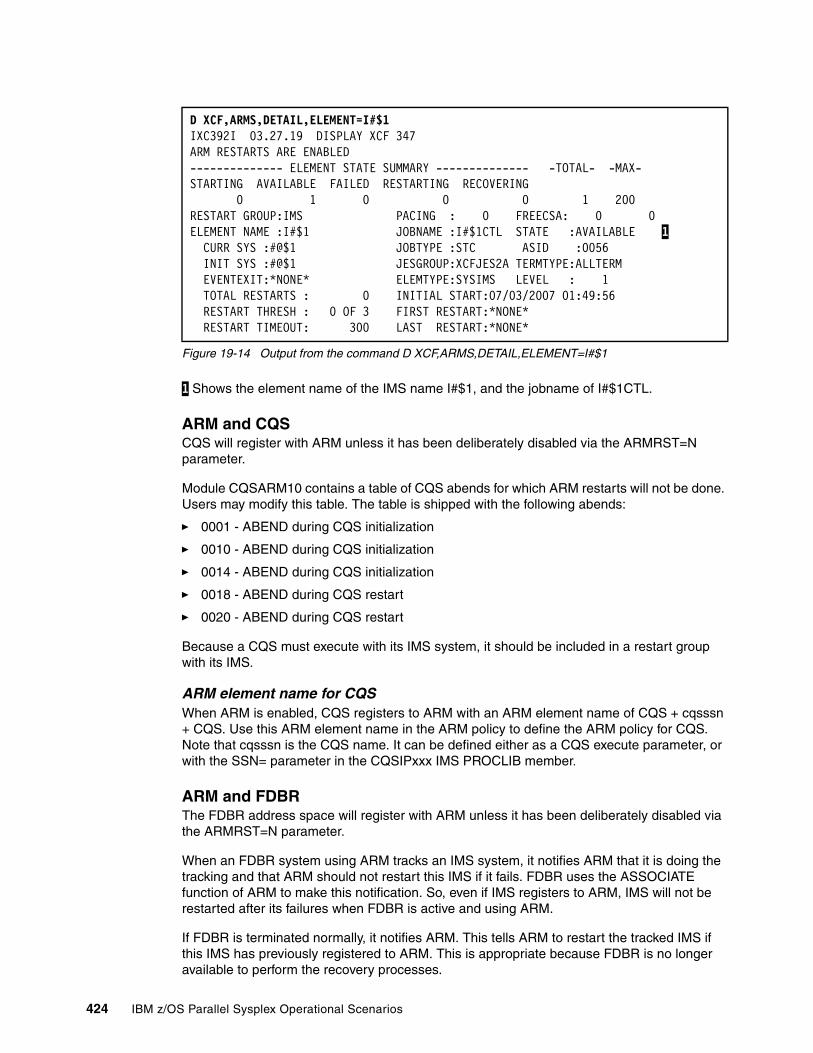
Figure 19-14 Output from the command D XCF,ARMS,DETAIL,ELEMENT=I#$1
1 Shows the element name of the IMS name I#$1, and the jobname of I#$1CTL.
ARM and CQSCQS will register with ARM unless it has been deliberately disabled via the ARMRST=N parameter.
Module CQSARM10 contains a table of CQS abends for which ARM restarts will not be done. Users may modify this table. The table is shipped with the following abends:
� 0001 - ABEND during CQS initialization
� 0010 - ABEND during CQS initialization
� 0014 - ABEND during CQS initialization
� 0018 - ABEND during CQS restart
� 0020 - ABEND during CQS restart
Because a CQS must execute with its IMS system, it should be included in a restart group with its IMS.
ARM element name for CQSWhen ARM is enabled, CQS registers to ARM with an ARM element name of CQS + cqsssn + CQS. Use this ARM element name in the ARM policy to define the ARM policy for CQS. Note that cqsssn is the CQS name. It can be defined either as a CQS execute parameter, or with the SSN= parameter in the CQSIPxxx IMS PROCLIB member.
ARM and FDBRThe FDBR address space will register with ARM unless it has been deliberately disabled via the ARMRST=N parameter.
When an FDBR system using ARM tracks an IMS system, it notifies ARM that it is doing the tracking and that ARM should not restart this IMS if it fails. FDBR uses the ASSOCIATE function of ARM to make this notification. So, even if IMS registers to ARM, IMS will not be restarted after its failures when FDBR is active and using ARM.
If FDBR is terminated normally, it notifies ARM. This tells ARM to restart the tracked IMS if this IMS has previously registered to ARM. This is appropriate because FDBR is no longer available to perform the recovery processes.
D XCF,ARMS,DETAIL,ELEMENT=I#$1 IXC392I 03.27.19 DISPLAY XCF 347 ARM RESTARTS ARE ENABLED -------------- ELEMENT STATE SUMMARY -------------- -TOTAL- -MAX- STARTING AVAILABLE FAILED RESTARTING RECOVERING 0 1 0 0 0 1 200 RESTART GROUP:IMS PACING : 0 FREECSA: 0 0 ELEMENT NAME :I#$1 JOBNAME :I#$1CTL STATE :AVAILABLE 1 CURR SYS :#@$1 JOBTYPE :STC ASID :0056 INIT SYS :#@$1 JESGROUP:XCFJES2A TERMTYPE:ALLTERM EVENTEXIT:*NONE* ELEMTYPE:SYSIMS LEVEL : 1 TOTAL RESTARTS : 0 INITIAL START:07/03/2007 01:49:56 RESTART THRESH : 0 OF 3 FIRST RESTART:*NONE* RESTART TIMEOUT: 300 LAST RESTART:*NONE*
424 IBM z/OS Parallel Sysplex Operational Scenarios
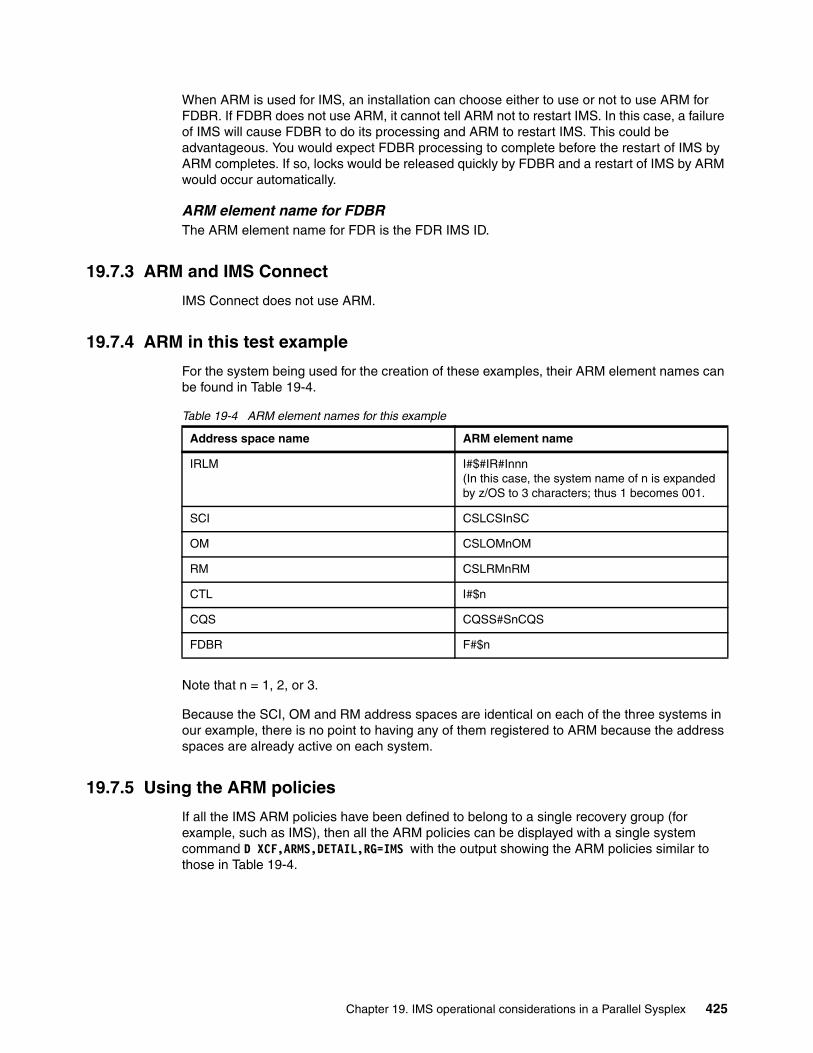
When ARM is used for IMS, an installation can choose either to use or not to use ARM for FDBR. If FDBR does not use ARM, it cannot tell ARM not to restart IMS. In this case, a failure of IMS will cause FDBR to do its processing and ARM to restart IMS. This could be advantageous. You would expect FDBR processing to complete before the restart of IMS by ARM completes. If so, locks would be released quickly by FDBR and a restart of IMS by ARM would occur automatically.
ARM element name for FDBRThe ARM element name for FDR is the FDR IMS ID.
19.7.3 ARM and IMS Connect
IMS Connect does not use ARM.
19.7.4 ARM in this test example
For the system being used for the creation of these examples, their ARM element names can be found in Table 19-4.
Table 19-4 ARM element names for this example
Note that n = 1, 2, or 3.
Because the SCI, OM and RM address spaces are identical on each of the three systems in our example, there is no point to having any of them registered to ARM because the address spaces are already active on each system.
19.7.5 Using the ARM policies
If all the IMS ARM policies have been defined to belong to a single recovery group (for example, such as IMS), then all the ARM policies can be displayed with a single system command D XCF,ARMS,DETAIL,RG=IMS with the output showing the ARM policies similar to those in Table 19-4.
Address space name ARM element name
IRLM I#$#IR#Innn (In this case, the system name of n is expanded by z/OS to 3 characters; thus 1 becomes 001.
SCI CSLCSInSC
OM CSLOMnOM
RM CSLRMnRM
CTL I#$n
CQS CQSS#SnCQS
FDBR F#$n
Chapter 19. IMS operational considerations in a Parallel Sysplex 425
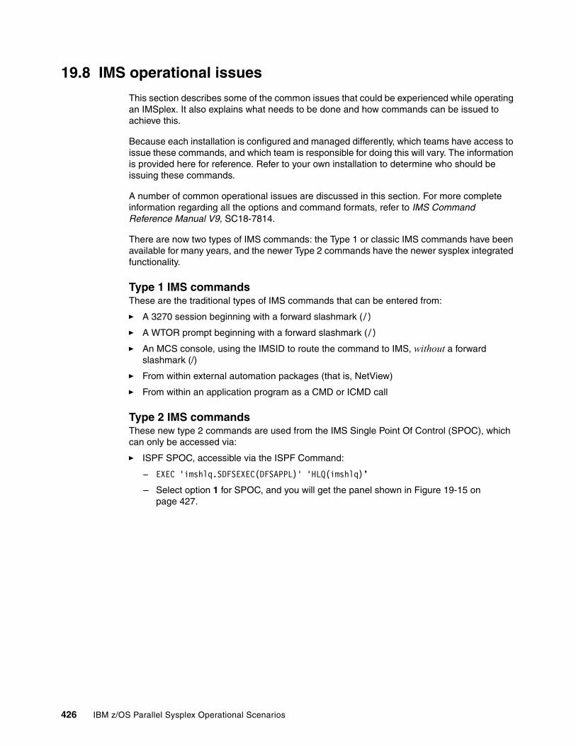
19.8 IMS operational issues
This section describes some of the common issues that could be experienced while operating an IMSplex. It also explains what needs to be done and how commands can be issued to achieve this.
Because each installation is configured and managed differently, which teams have access to issue these commands, and which team is responsible for doing this will vary. The information is provided here for reference. Refer to your own installation to determine who should be issuing these commands.
A number of common operational issues are discussed in this section. For more complete information regarding all the options and command formats, refer to IMS Command Reference Manual V9, SC18-7814.
There are now two types of IMS commands: the Type 1 or classic IMS commands have been available for many years, and the newer Type 2 commands have the newer sysplex integrated functionality.
Type 1 IMS commandsThese are the traditional types of IMS commands that can be entered from:
� A 3270 session beginning with a forward slashmark (/)
� A WTOR prompt beginning with a forward slashmark (/)
� An MCS console, using the IMSID to route the command to IMS, without a forward slashmark (/)
� From within external automation packages (that is, NetView)
� From within an application program as a CMD or ICMD call
Type 2 IMS commandsThese new type 2 commands are used from the IMS Single Point Of Control (SPOC), which can only be accessed via:
� ISPF SPOC, accessible via the ISPF Command:
– EXEC 'imshlq.SDFSEXEC(DFSAPPL)' 'HLQ(imshlq)’
– Select option 1 for SPOC, and you will get the panel shown in Figure 19-15 on page 427.
426 IBM z/OS Parallel Sysplex Operational Scenarios
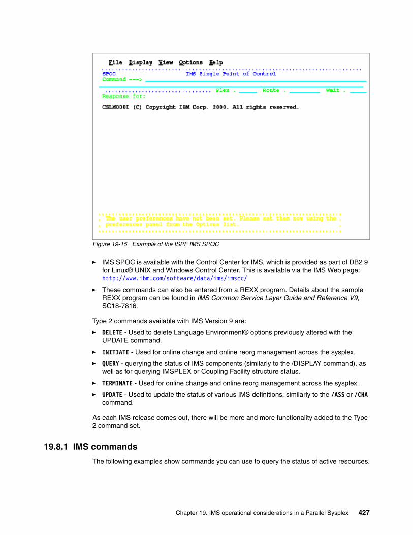
Figure 19-15 Example of the ISPF IMS SPOC
� IMS SPOC is available with the Control Center for IMS, which is provided as part of DB2 9 for Linux® UNIX and Windows Control Center. This is available via the IMS Web page: http://www.ibm.com/software/data/ims/imscc/
� These commands can also be entered from a REXX program. Details about the sample REXX program can be found in IMS Common Service Layer Guide and Reference V9, SC18-7816.
Type 2 commands available with IMS Version 9 are:
� DELETE - Used to delete Language Environment® options previously altered with the UPDATE command.
� INITIATE - Used for online change and online reorg management across the sysplex.
� QUERY - querying the status of IMS components (similarly to the /DISPLAY command), as well as for querying IMSPLEX or Coupling Facility structure status.
� TERMINATE - Used for online change and online reorg management across the sysplex.
� UPDATE - Used to update the status of various IMS definitions, similarly to the /ASS or /CHA command.
As each IMS release comes out, there will be more and more functionality added to the Type 2 command set.
19.8.1 IMS commands
The following examples show commands you can use to query the status of active resources.
Chapter 19. IMS operational considerations in a Parallel Sysplex 427

Type 1 commandsThese commands would not normally cover sysplex-related functions.
� Displaying the active regions.
� Displaying connection to other subsystems (that is, DB2, MQ, OTMA, and so on).
� Displaying the status of a particular resource.
Type 2 commandsThese commands are designed for sysplex-related functions.
� Displaying the status of a particular resource.
� Display the status of the different components of an IMSplex.
� Display the status of the Coupling Facility structures.
19.8.2 CQS commands
A number of CQS commands can be issued from within IMS. These are related to the Shared Queues list structures for Message Queues and Fast Path Expedited Message Handler queues.
CQS queriesThe CQS structures can be queried by using the /CQQ IMS command. As shown in Figure 19-16, the command displays:
1 LEALLOC the list entries allocated. 2 LEINUSE the list entries in use. 3 ELMALLOC the elements allocated. 4 ELMINUSE the elements in use.
Figure 19-16 IMS response to the command /CQQ STATISTICS STRUCTURE ALL
CQS checkpointsCQS Checkpoints for individual Coupling Facility list structures can be triggered by the IMS command /CQCHKPT or /CQC. An example is shown in Figure 19-17.
Figure 19-17 IMS response to the command /CQC SHAREDQ STRUCTURE ALL
CQS Set commandUse the /CQSET or /CQS command to tell CQS whether to take a structure checkpoint during normal shutdown or not, for example /CQSET SHUTDOWN SHAREDQ ON STRUCTURE ALL.
After it is issued, CQS will always shut down along with IMS; otherwise, it will remain active.
TRUCTURE NAME LEALLOC1 LEINUSE2 ELMALLOC3 ELMINUSE4 LE/EL I#$#MSGQ 7570 6 7613 5 0001/0001I#$#MSGQOFLW N/A N/A N/A N/A N/A I#$#EMHQ 7570 6 7613 5 0001/0001I#$#EMHQOFLW N/A N/A N/A N/A N/A
DFS058I 21:15:15 CQCHKPT COMMAND IN PROGRESS I#$1 DFS1972I CQCHKPT SHAREDQ COMMAND COMPLETE FOR STRUCTURE=I#$#MSGQDFS1972I CQCHKPT SHAREDQ COMMAND COMPLETE FOR STRUCTURE=I#$#EMHQ
428 IBM z/OS Parallel Sysplex Operational Scenarios

19.8.3 IRLM commands
Each IMS image will have a unique IMSID, which can be determined from the respective outstanding reply.
The IMS workload is now on more than one system, where each has access to the same set of databases. Control of this access is managed by IRLM.
The communication with IRLM is accomplished by using the standard z/OS modify command with various options.
STATUS optionThe command F irlmproc,STATUS displays status, work units in progress, and detailed lock information for each DBMS identified to this instance of IRLM (irlmproc is the procedure name for the IRLM address space.) Figure 19-18 is an example showing an IMS control region and an FDR region on each system.
Figure 19-18 Response from an IRLM STATUS command F I#$#IRLM,STATUS
1 This shows the FDBR region active in READ ONLY mode. 2 This shows the IMS system active, with two held locks.
STATUS,ALLD optionThe ALLD option shows all the subsystems connected to all the IRLMs in the data sharing group that IRLM belongs to. The RET_LKS field is very important. It shows how many database records are retained by a failing IRLM and is therefore unavailable to any other IMS subsystem. See Figure 19-19 for an example.
Figure 19-19 Response from an IRLM STATUS command F I#$#IRLM,STATUS,ALLD
1 This shows all the FDBR regions active with READ ONLY mode, and which IRLM they are connected to. 2 This shows the IMS systems, together with which IRLM they are connected to.
DXR101I IR#I001 STATUS SCOPE=GLOBAL 662 DEADLOCK: 0500 SUBSYSTEMS IDENTIFIED NAME T/OUT STATUS UNITS HELD WAITING RET_LKSFDRI#$3 0300 UP-RO 0 0 0 01I#$1 0300 UP 1 2 0 02 DXR101I End of display
DXR102I IR#I001 STATUS 731SUBSYSTEMS IDENTIFIED NAME STATUS RET_LKS IRLMID IRLM_NAME IRLM_LEVL FDRI#$1 UP-RO 0 002 IR#I 1.009 1 FDRI#$2 UP-RO 0 003 IR#I 1.009 FDRI#$3 UP-RO 0 001 IR#I 1.009 I#$1 UP 0 001 IR#I 1.009 2 I#$2 UP 0 002 IR#I 1.009 I#$3 UP 0 003 IR#I 1.009 DXR102I End of display
Chapter 19. IMS operational considerations in a Parallel Sysplex 429
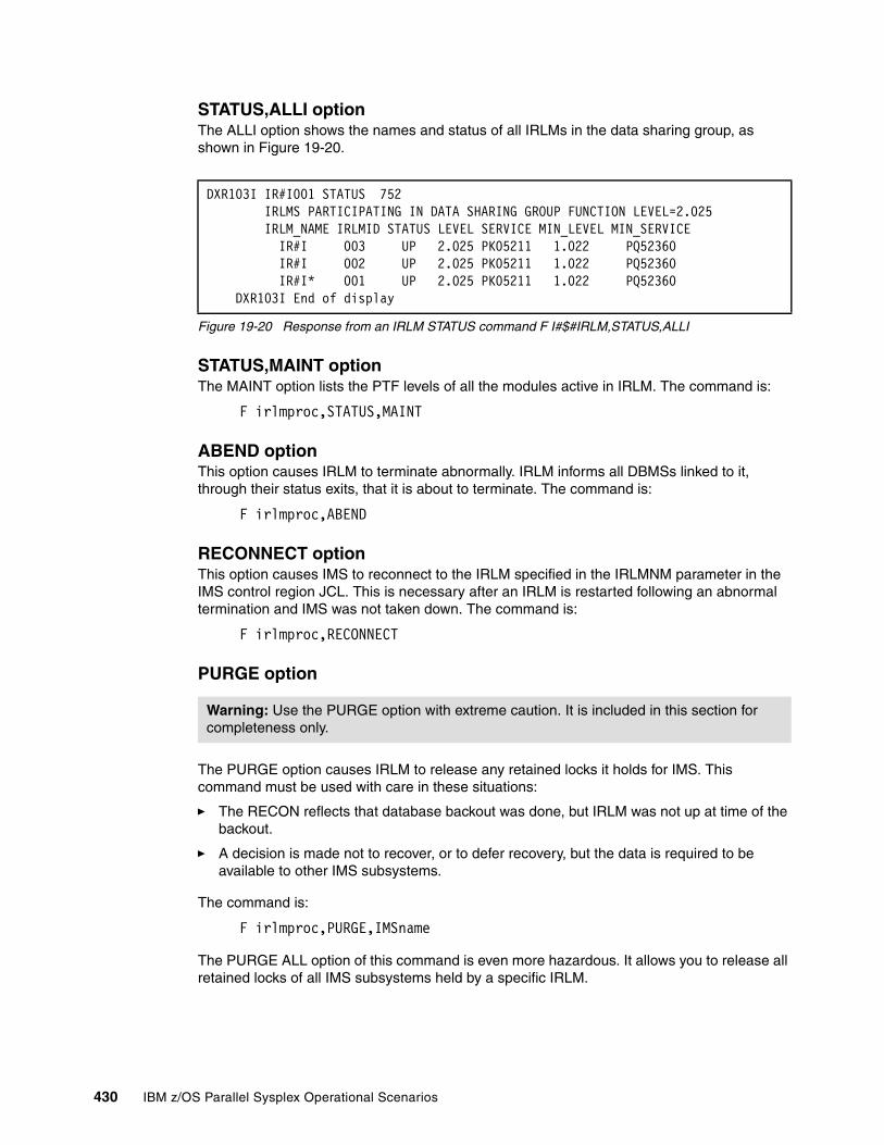
STATUS,ALLI optionThe ALLI option shows the names and status of all IRLMs in the data sharing group, as shown in Figure 19-20.
Figure 19-20 Response from an IRLM STATUS command F I#$#IRLM,STATUS,ALLI
STATUS,MAINT optionThe MAINT option lists the PTF levels of all the modules active in IRLM. The command is:
F irlmproc,STATUS,MAINT
ABEND optionThis option causes IRLM to terminate abnormally. IRLM informs all DBMSs linked to it, through their status exits, that it is about to terminate. The command is:
F irlmproc,ABEND
RECONNECT optionThis option causes IMS to reconnect to the IRLM specified in the IRLMNM parameter in the IMS control region JCL. This is necessary after an IRLM is restarted following an abnormal termination and IMS was not taken down. The command is:
F irlmproc,RECONNECT
PURGE option
The PURGE option causes IRLM to release any retained locks it holds for IMS. This command must be used with care in these situations:
� The RECON reflects that database backout was done, but IRLM was not up at time of the backout.
� A decision is made not to recover, or to defer recovery, but the data is required to be available to other IMS subsystems.
The command is:
F irlmproc,PURGE,IMSname
The PURGE ALL option of this command is even more hazardous. It allows you to release all retained locks of all IMS subsystems held by a specific IRLM.
DXR103I IR#I001 STATUS 752 IRLMS PARTICIPATING IN DATA SHARING GROUP FUNCTION LEVEL=2.025 IRLM_NAME IRLMID STATUS LEVEL SERVICE MIN_LEVEL MIN_SERVICE IR#I 003 UP 2.025 PK05211 1.022 PQ52360 IR#I 002 UP 2.025 PK05211 1.022 PQ52360 IR#I* 001 UP 2.025 PK05211 1.022 PQ52360 DXR103I End of display
Warning: Use the PURGE option with extreme caution. It is included in this section for completeness only.
430 IBM z/OS Parallel Sysplex Operational Scenarios
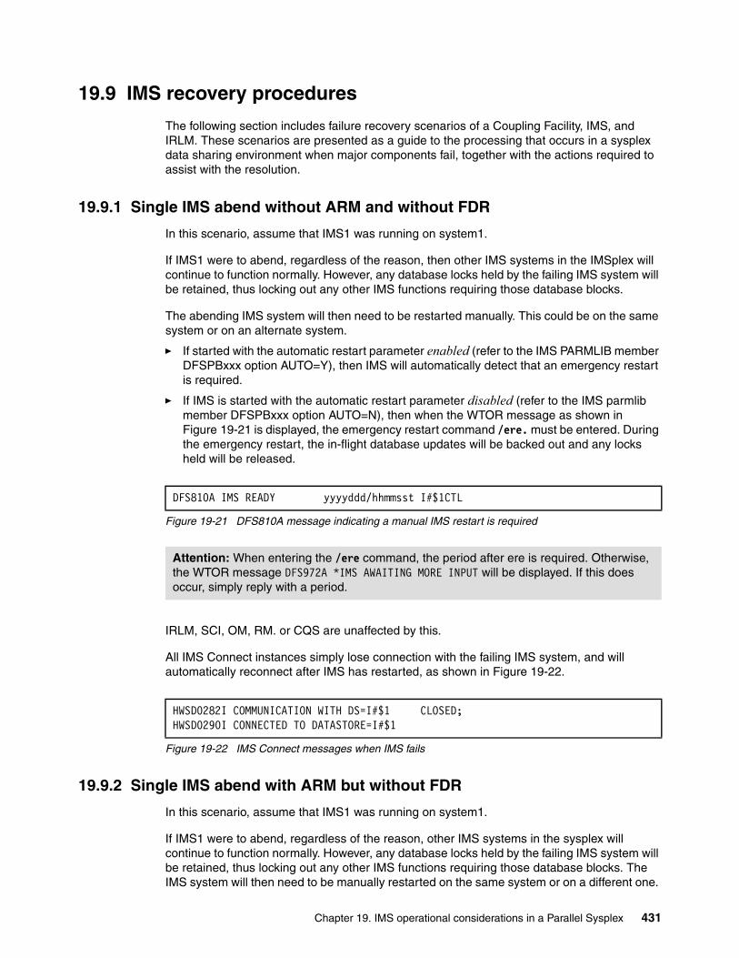
19.9 IMS recovery procedures
The following section includes failure recovery scenarios of a Coupling Facility, IMS, and IRLM. These scenarios are presented as a guide to the processing that occurs in a sysplex data sharing environment when major components fail, together with the actions required to assist with the resolution.
19.9.1 Single IMS abend without ARM and without FDR
In this scenario, assume that IMS1 was running on system1.
If IMS1 were to abend, regardless of the reason, then other IMS systems in the IMSplex will continue to function normally. However, any database locks held by the failing IMS system will be retained, thus locking out any other IMS functions requiring those database blocks.
The abending IMS system will then need to be restarted manually. This could be on the same system or on an alternate system.
� If started with the automatic restart parameter enabled (refer to the IMS PARMLIB member DFSPBxxx option AUTO=Y), then IMS will automatically detect that an emergency restart is required.
� If IMS is started with the automatic restart parameter disabled (refer to the IMS parmlib member DFSPBxxx option AUTO=N), then when the WTOR message as shown in Figure 19-21 is displayed, the emergency restart command /ere. must be entered. During the emergency restart, the in-flight database updates will be backed out and any locks held will be released.
Figure 19-21 DFS810A message indicating a manual IMS restart is required
IRLM, SCI, OM, RM. or CQS are unaffected by this.
All IMS Connect instances simply lose connection with the failing IMS system, and will automatically reconnect after IMS has restarted, as shown in Figure 19-22.
Figure 19-22 IMS Connect messages when IMS fails
19.9.2 Single IMS abend with ARM but without FDR
In this scenario, assume that IMS1 was running on system1.
If IMS1 were to abend, regardless of the reason, other IMS systems in the sysplex will continue to function normally. However, any database locks held by the failing IMS system will be retained, thus locking out any other IMS functions requiring those database blocks. The IMS system will then need to be manually restarted on the same system or on a different one.
DFS810A IMS READY yyyyddd/hhmmsst I#$1CTL
Attention: When entering the /ere command, the period after ere is required. Otherwise, the WTOR message DFS972A *IMS AWAITING MORE INPUT will be displayed. If this does occur, simply reply with a period.
HWSD0282I COMMUNICATION WITH DS=I#$1 CLOSED;HWSD0290I CONNECTED TO DATASTORE=I#$1
Chapter 19. IMS operational considerations in a Parallel Sysplex 431
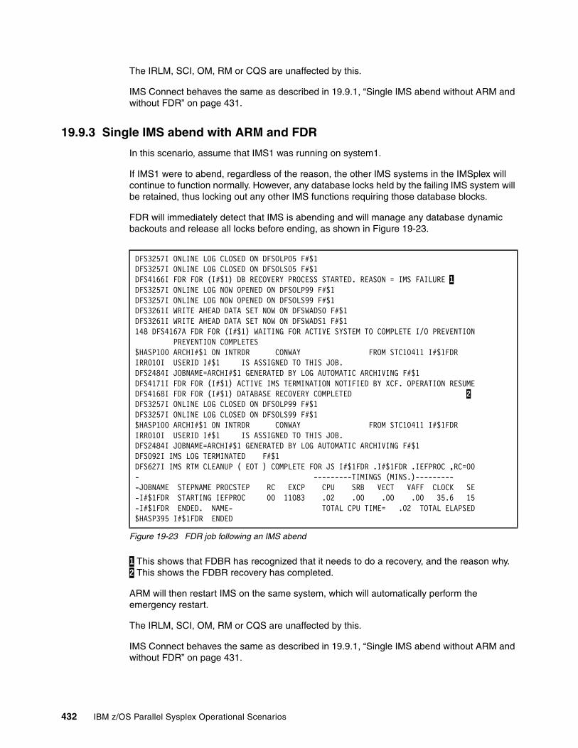
The IRLM, SCI, OM, RM or CQS are unaffected by this.
IMS Connect behaves the same as described in 19.9.1, “Single IMS abend without ARM and without FDR” on page 431.
19.9.3 Single IMS abend with ARM and FDR
In this scenario, assume that IMS1 was running on system1.
If IMS1 were to abend, regardless of the reason, the other IMS systems in the IMSplex will continue to function normally. However, any database locks held by the failing IMS system will be retained, thus locking out any other IMS functions requiring those database blocks.
FDR will immediately detect that IMS is abending and will manage any database dynamic backouts and release all locks before ending, as shown in Figure 19-23.
Figure 19-23 FDR job following an IMS abend
1 This shows that FDBR has recognized that it needs to do a recovery, and the reason why. 2 This shows the FDBR recovery has completed.
ARM will then restart IMS on the same system, which will automatically perform the emergency restart.
The IRLM, SCI, OM, RM or CQS are unaffected by this.
IMS Connect behaves the same as described in 19.9.1, “Single IMS abend without ARM and without FDR” on page 431.
DFS3257I ONLINE LOG CLOSED ON DFSOLP05 F#$1 DFS3257I ONLINE LOG CLOSED ON DFSOLS05 F#$1 DFS4166I FDR FOR (I#$1) DB RECOVERY PROCESS STARTED. REASON = IMS FAILURE 1DFS3257I ONLINE LOG NOW OPENED ON DFSOLP99 F#$1 DFS3257I ONLINE LOG NOW OPENED ON DFSOLS99 F#$1 DFS3261I WRITE AHEAD DATA SET NOW ON DFSWADS0 F#$1 DFS3261I WRITE AHEAD DATA SET NOW ON DFSWADS1 F#$1 148 DFS4167A FDR FOR (I#$1) WAITING FOR ACTIVE SYSTEM TO COMPLETE I/O PREVENTION PREVENTION COMPLETES $HASP100 ARCHI#$1 ON INTRDR CONWAY FROM STC10411 I#$1FDR IRR010I USERID I#$1 IS ASSIGNED TO THIS JOB. DFS2484I JOBNAME=ARCHI#$1 GENERATED BY LOG AUTOMATIC ARCHIVING F#$1 DFS4171I FDR FOR (I#$1) ACTIVE IMS TERMINATION NOTIFIED BY XCF. OPERATION RESUMEDFS4168I FDR FOR (I#$1) DATABASE RECOVERY COMPLETED 2 DFS3257I ONLINE LOG CLOSED ON DFSOLP99 F#$1 DFS3257I ONLINE LOG CLOSED ON DFSOLS99 F#$1 $HASP100 ARCHI#$1 ON INTRDR CONWAY FROM STC10411 I#$1FDR IRR010I USERID I#$1 IS ASSIGNED TO THIS JOB. DFS2484I JOBNAME=ARCHI#$1 GENERATED BY LOG AUTOMATIC ARCHIVING F#$1 DFS092I IMS LOG TERMINATED F#$1 DFS627I IMS RTM CLEANUP ( EOT ) COMPLETE FOR JS I#$1FDR .I#$1FDR .IEFPROC ,RC=00- ---------TIMINGS (MINS.)--------- -JOBNAME STEPNAME PROCSTEP RC EXCP CPU SRB VECT VAFF CLOCK SE-I#$1FDR STARTING IEFPROC 00 11083 .02 .00 .00 .00 35.6 15-I#$1FDR ENDED. NAME- TOTAL CPU TIME= .02 TOTAL ELAPSED$HASP395 I#$1FDR ENDED
432 IBM z/OS Parallel Sysplex Operational Scenarios
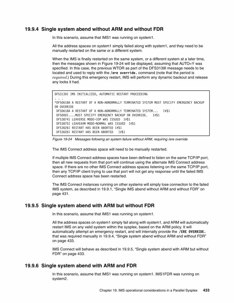
19.9.4 Single system abend without ARM and without FDR
In this scenario, assume that IMS1 was running on system1.
All the address spaces on system1 simply failed along with system1, and they need to be manually restarted on the same or a different system.
When the IMS is finally restarted on the same system, or a different system at a later time, then the messages shown in Figure 19-24 will be displayed, assuming that AUTO=Y was specified. In this case, the previous WTOR as part of the DFS3139I message needs to be located and used to reply with the /ere override. command (note that the period is required.) During this emergency restart, IMS will perform any dynamic backout and release any locks it had.
Figure 19-24 Messages following an system failure without ARM, requiring /ere override
The IMS Connect address space will need to be manually restarted.
If multiple IMS Connect address spaces have been defined to listen on the same TCP/IP port, then all new requests from that port will continue using the alternate IMS Connect address space. If there are no other IMS Connect address spaces listening on the same TCP/IP port, then any TCP/IP client trying to use that port will not get any response until the failed IMS Connect address space has been restarted.
The IMS Connect instances running on other systems will simply lose connection to the failed IMS system, as described in 19.9.1, “Single IMS abend without ARM and without FDR” on page 431.
19.9.5 Single system abend with ARM but without FDR
In this scenario, assume that IMS1 was running on system1.
All the address spaces on system1 simply fail along with system1, and ARM will automatically restart IMS on any valid system within the sysplex, based on the ARM policy. It will automatically attempt an emergency restart, and will internally provide the /ERE OVERRIDE. that was required manually in 19.9.4, “Single system abend without ARM and without FDR” on page 433.
IMS Connect will behave as described in 19.9.5, “Single system abend with ARM but without FDR” on page 433.
19.9.6 Single system abend with ARM and FDR
In this scenario, assume that IMS1 was running on system1. IMS1FDR was running on system2.
DFS3139I IMS INITIALIZED, AUTOMATIC RESTART PROCEEDING. . .*DFS0618A A RESTART OF A NON-ABNORMALLY TERMINATED SYSTEM MUST SPECIFY EMERGENCY BACKUP OR OVERRIDE DFS0618A A RESTART OF A NON-ABNORMALLY TERMINATED SYSTEM... I#$1 DFS000I....MUST SPECIFY EMERGENCY BACKUP OR OVERRIDE. I#$1 DFS3874I LEAVERSE MODE=IOP WAS ISSUED I#$1 DFS3875I LEAVEAVM MODE=NORMAL WAS ISSUED I#$1 DFS3626I RESTART HAS BEEN ABORTED I#$1 DFS3626I RESTART HAS BEEN ABORTED I#$1
Chapter 19. IMS operational considerations in a Parallel Sysplex 433
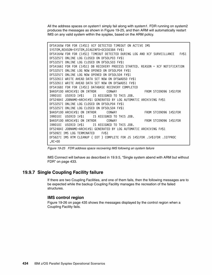
All the address spaces on system1 simply fail along with system1. FDR running on system2 produces the messages as shown in Figure 19-25, and then ARM will automatically restart IMS on any valid system within the sysplex, based on the ARM policy.
Figure 19-25 FDR address space recovering IMS following an system failure
IMS Connect will behave as described in 19.9.5, “Single system abend with ARM but without FDR” on page 433.
19.9.7 Single Coupling Facility failure
If there are two Coupling Facilities, and one of them fails, then the following messages are to be expected while the backup Coupling Facility manages the recreation of the failed structures.
IMS control regionFigure 19-26 on page 435 shows the messages displayed by the control region when a Coupling Facility fails.
DFS4165W FDR FOR (I#$1) XCF DETECTED TIMEOUT ON ACTIVE IMS SYSTEM,REASON=SYSTEM,DIAGINFO=0C030384 F#$1DFS4164W FDR FOR (I#$1) TIMEOUT DETECTED DURING LOG AND XCF SURVEILLANCE F#$1DFS3257I ONLINE LOG CLOSED ON DFSOLP03 F#$1 DFS3257I ONLINE LOG CLOSED ON DFSOLS03 F#$1 DFS4166I FDR FOR (I#$1) DB RECOVERY PROCESS STARTED. REASON = XCF NOTIFICATION DFS3257I ONLINE LOG NOW OPENED ON DFSOLP04 F#$1 DFS3257I ONLINE LOG NOW OPENED ON DFSOLS04 F#$1 DFS3261I WRITE AHEAD DATA SET NOW ON DFSWADS0 F#$1 DFS3261I WRITE AHEAD DATA SET NOW ON DFSWADS1 F#$1 DFS4168I FDR FOR (I#$1) DATABASE RECOVERY COMPLETED $HASP100 ARCHI#$1 ON INTRDR CONWAY FROM STC09096 I#$1FDR IRR010I USERID I#$1 IS ASSIGNED TO THIS JOB. DFS2484I JOBNAME=ARCHI#$1 GENERATED BY LOG AUTOMATIC ARCHIVING F#$1 DFS3257I ONLINE LOG CLOSED ON DFSOLP04 F#$1 DFS3257I ONLINE LOG CLOSED ON DFSOLS04 F#$1 $HASP100 ARCHI#$1 ON INTRDR CONWAY FROM STC09096 I#$1FDR IRR010I USERID I#$1 IS ASSIGNED TO THIS JOB. $HASP100 ARCHI#$1 ON INTRDR CONWAY FROM STC09096 I#$1FDR IRR010I USERID I#$1 IS ASSIGNED TO THIS JOB. DFS2484I JOBNAME=ARCHI#$1 GENERATED BY LOG AUTOMATIC ARCHIVING F#$1 DFS092I IMS LOG TERMINATED F#$1 DFS627I IMS RTM CLEANUP ( EOT ) COMPLETE FOR JS I#$1FDR .I#$1FDR .IEFPROC ,RC=00
434 IBM z/OS Parallel Sysplex Operational Scenarios
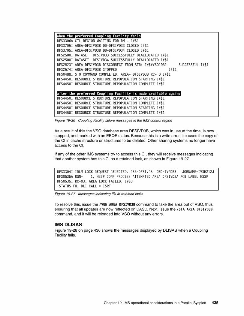
Figure 19-26 Coupling Facility failure messages in the IMS control region
As a result of this the VSO database area DFSIVD3B, which was in use at the time, is now stopped, and marked with an EEQE status. Because this is a write error, it causes the copy of the CI in cache structure or structures to be deleted. Other sharing systems no longer have access to the CI.
If any of the other IMS systems try to access this CI, they will receive messages indicating that another system has this CI as a retained lock, as shown in Figure 19-27.
Figure 19-27 Messages indicating IRLM retained locks
To resolve this, issue the /VUN AREA DFSIVD3B command to take the area out of VSO, thus ensuring that all updates are now reflected on DASD. Next, issue the /STA AREA DFSIVD3B command, and it will be reloaded into VSO without any errors.
IMS DLISASFigure 19-28 on page 436 shows the messages displayed by DLISAS when a Coupling Facility fails.
when the preferred Coupling Facility failsDFS3306A CTL REGION WAITING FOR RM - I#$1 DFS3705I AREA=DFSIVD3B DD=DFSIVD33 CLOSED I#$1 DFS3705I AREA=DFSIVD3B DD=DFSIVD34 CLOSED I#$1 DFS2500I DATASET DFSIVD33 SUCCESSFULLY DEALLOCATED I#$1 DFS2500I DATASET DFSIVD34 SUCCESSFULLY DEALLOCATED I#$1 DFS2823I AREA DFSIVD3B DISCONNECT FROM STR: I#$#VSO1DB2 SUCCESSFUL I#$1 DFS2574I AREA=DFSIVD3B STOPPED I#$1 DFS0488I STO COMMAND COMPLETED. AREA= DFSIVD3B RC= 0 I#$1 DFS4450I RESOURCE STRUCTURE REPOPULATION STARTING I#$1 DFS4450I RESOURCE STRUCTURE REPOPULATION COMPLETE I#$1
after the preferred Coupling Facility is made available again:DFS4450I RESOURCE STRUCTURE REPOPULATION STARTING I#$1DFS4450I RESOURCE STRUCTURE REPOPULATION COMPLETE I#$1DFS4450I RESOURCE STRUCTURE REPOPULATION STARTING I#$1DFS4450I RESOURCE STRUCTURE REPOPULATION COMPLETE I#$1
DFS3304I IRLM LOCK REQUEST REJECTED. PSB=DFSIVP8 DBD=IVPDB3 JOBNAME=IV3H212J DFS0535A RGN= 1, HSSP CONN PROCESS ATTEMPTED AREA DFSIVD3A PCB LABEL HSSP DFS0535I RC=03, AREA LOCK FAILED. I#$3 +STATUS FH, DLI CALL = ISRT
Chapter 19. IMS operational considerations in a Parallel Sysplex 435
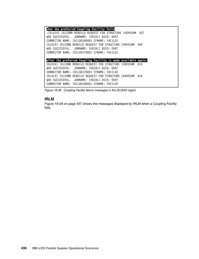
Figure 19-28 Coupling Facility failure messages in the DLISAS region
IRLMFigure 19-29 on page 437 shows the messages displayed by IRLM when a Coupling Facility fails.
when the preferred Coupling Facility fails:IXL014I IXLCONN REBUILD REQUEST FOR STRUCTURE I#$#OSAM 437WAS SUCCESSFUL. JOBNAME: I#$1DLI ASID: 0047 CONNECTOR NAME: IXCLO0180001 CFNAME: FACIL01 IXL014I IXLCONN REBUILD REQUEST FOR STRUCTURE I#$#VSAM 440WAS SUCCESSFUL. JOBNAME: I#$1DLI ASID: 0047 CONNECTOR NAME: IXCLO0170001 CFNAME: FACIL01
after the preferred Coupling Facility is made available again:IXL014I IXLCONN REBUILD REQUEST FOR STRUCTURE I#$#VSAM 615WAS SUCCESSFUL. JOBNAME: I#$1DLI ASID: 0047 CONNECTOR NAME: IXCLO0170001 CFNAME: FACIL02 IXL014I IXLCONN REBUILD REQUEST FOR STRUCTURE I#$#OSAM 616WAS SUCCESSFUL. JOBNAME: I#$1DLI ASID: 0047 CONNECTOR NAME: IXCLO0180001 CFNAME: FACIL02
436 IBM z/OS Parallel Sysplex Operational Scenarios
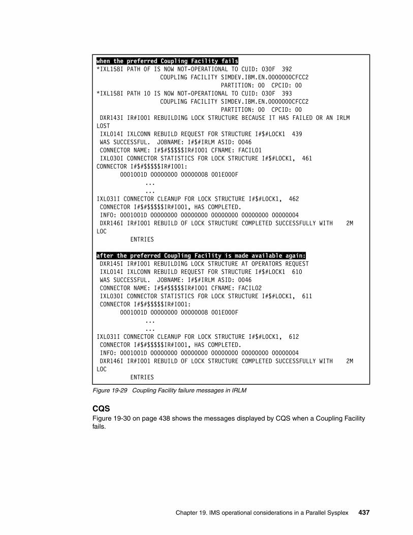
Figure 19-29 Coupling Facility failure messages in IRLM
CQSFigure 19-30 on page 438 shows the messages displayed by CQS when a Coupling Facility fails.
when the preferred Coupling Facility fails*IXL158I PATH 0F IS NOW NOT-OPERATIONAL TO CUID: 030F 392 COUPLING FACILITY SIMDEV.IBM.EN.0000000CFCC2 PARTITION: 00 CPCID: 00 *IXL158I PATH 10 IS NOW NOT-OPERATIONAL TO CUID: 030F 393 COUPLING FACILITY SIMDEV.IBM.EN.0000000CFCC2 PARTITION: 00 CPCID: 00 DXR143I IR#I001 REBUILDING LOCK STRUCTURE BECAUSE IT HAS FAILED OR AN IRLM LOST IXL014I IXLCONN REBUILD REQUEST FOR STRUCTURE I#$#LOCK1 439 WAS SUCCESSFUL. JOBNAME: I#$#IRLM ASID: 0046 CONNECTOR NAME: I#$#$$$$$IR#I001 CFNAME: FACIL01 IXL030I CONNECTOR STATISTICS FOR LOCK STRUCTURE I#$#LOCK1, 461 CONNECTOR I#$#$$$$$IR#I001: 0001001D 00000000 00000008 001E000F
...
...IXL031I CONNECTOR CLEANUP FOR LOCK STRUCTURE I#$#LOCK1, 462 CONNECTOR I#$#$$$$$IR#I001, HAS COMPLETED. INFO: 0001001D 00000000 00000000 00000000 00000000 00000004 DXR146I IR#I001 REBUILD OF LOCK STRUCTURE COMPLETED SUCCESSFULLY WITH 2M LOC ENTRIES
after the preferred Coupling Facility is made available again: DXR145I IR#I001 REBUILDING LOCK STRUCTURE AT OPERATORS REQUEST IXL014I IXLCONN REBUILD REQUEST FOR STRUCTURE I#$#LOCK1 610 WAS SUCCESSFUL. JOBNAME: I#$#IRLM ASID: 0046 CONNECTOR NAME: I#$#$$$$$IR#I001 CFNAME: FACIL02 IXL030I CONNECTOR STATISTICS FOR LOCK STRUCTURE I#$#LOCK1, 611 CONNECTOR I#$#$$$$$IR#I001: 0001001D 00000000 00000008 001E000F
...
...IXL031I CONNECTOR CLEANUP FOR LOCK STRUCTURE I#$#LOCK1, 612 CONNECTOR I#$#$$$$$IR#I001, HAS COMPLETED. INFO: 0001001D 00000000 00000000 00000000 00000000 00000004 DXR146I IR#I001 REBUILD OF LOCK STRUCTURE COMPLETED SUCCESSFULLY WITH 2M LOC ENTRIES
Chapter 19. IMS operational considerations in a Parallel Sysplex 437
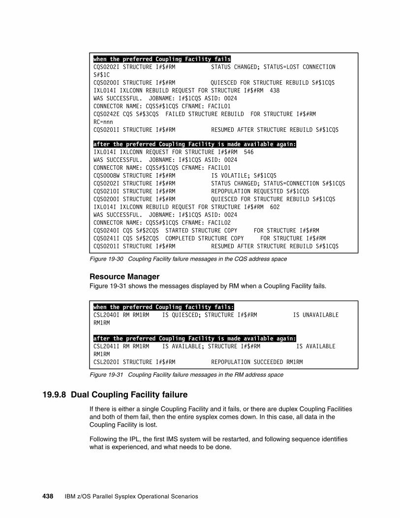
Figure 19-30 Coupling Facility failure messages in the CQS address space
Resource ManagerFigure 19-31 shows the messages displayed by RM when a Coupling Facility fails.
Figure 19-31 Coupling Facility failure messages in the RM address space
19.9.8 Dual Coupling Facility failure
If there is either a single Coupling Facility and it fails, or there are duplex Coupling Facilities and both of them fail, then the entire sysplex comes down. In this case, all data in the Coupling Facility is lost.
Following the IPL, the first IMS system will be restarted, and following sequence identifies what is experienced, and what needs to be done.
when the preferred Coupling Facility failsCQS0202I STRUCTURE I#$#RM STATUS CHANGED; STATUS=LOST CONNECTION S#$1CCQS0200I STRUCTURE I#$#RM QUIESCED FOR STRUCTURE REBUILD S#$1CQS IXL014I IXLCONN REBUILD REQUEST FOR STRUCTURE I#$#RM 438 WAS SUCCESSFUL. JOBNAME: I#$1CQS ASID: 0024 CONNECTOR NAME: CQSS#$1CQS CFNAME: FACIL01 CQS0242E CQS S#$3CQS FAILED STRUCTURE REBUILD FOR STRUCTURE I#$#RM RC=nnnCQS0201I STRUCTURE I#$#RM RESUMED AFTER STRUCTURE REBUILD S#$1CQS
after the preferred Coupling Facility is made available again:IXL014I IXLCONN REQUEST FOR STRUCTURE I#$#RM 546 WAS SUCCESSFUL. JOBNAME: I#$1CQS ASID: 0024 CONNECTOR NAME: CQSS#$1CQS CFNAME: FACIL01 CQS0008W STRUCTURE I#$#RM IS VOLATILE; S#$1CQS CQS0202I STRUCTURE I#$#RM STATUS CHANGED; STATUS=CONNECTION S#$1CQSCQS0210I STRUCTURE I#$#RM REPOPULATION REQUESTED S#$1CQS CQS0200I STRUCTURE I#$#RM QUIESCED FOR STRUCTURE REBUILD S#$1CQS IXL014I IXLCONN REBUILD REQUEST FOR STRUCTURE I#$#RM 602 WAS SUCCESSFUL. JOBNAME: I#$1CQS ASID: 0024 CONNECTOR NAME: CQSS#$1CQS CFNAME: FACIL02 CQS0240I CQS S#$2CQS STARTED STRUCTURE COPY FOR STRUCTURE I#$#RM CQS0241I CQS S#$2CQS COMPLETED STRUCTURE COPY FOR STRUCTURE I#$#RM CQS0201I STRUCTURE I#$#RM RESUMED AFTER STRUCTURE REBUILD S#$1CQS
when the preferred Coupling facility fails:CSL2040I RM RM1RM IS QUIESCED; STRUCTURE I#$#RM IS UNAVAILABLE RM1RM
after the preferred Coupling Facility is made available again:CSL2041I RM RM1RM IS AVAILABLE; STRUCTURE I#$#RM IS AVAILABLE RM1RMCSL2020I STRUCTURE I#$#RM REPOPULATION SUCCEEDED RM1RM
438 IBM z/OS Parallel Sysplex Operational Scenarios
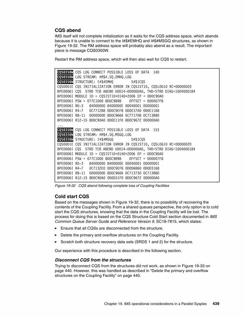
CQS abendIMS itself will not complete initialization as it waits for the CQS address space, which abends because it is unable to connect to the I#$#EMHQ and I#$#MSGQ structures, as shown in Figure 19-32. The RM address space will probably also abend as a result. The important piece is message CQS0350W.
Restart the RM address space, which will then also wait for CQS to restart.
Figure 19-32 CQS abend following complete loss of Coupling Facilities
Cold start CQSBased on the messages shown in Figure 19-32, there is no possibility of recovering the contents of the Coupling Facility. From a shared queues perspective, the only option is to cold start the CQS structures, knowing that the data in the Coupling Facility will be lost. The process for doing this is based on the CQS Structure Cold Start section documented in IMS Common Queue Server Guide and Reference Version 9, SC18-7815, which states:
� Ensure that all CQSs are disconnected from the structure.
� Delete the primary and overflow structures on the Coupling Facility.
� Scratch both structure recovery data sets (SRDS 1 and 2) for the structure.
Our experience with this procedure is described in the following section.
Disconnect CQS from the structuresTrying to disconnect CQS from the structures did not work, as shown in Figure 19-33 on page 440. However, this was handled as described in “Delete the primary and overflow structures on the Coupling Facility” on page 440.
CQS0350W CQS LOG CONNECT POSSIBLE LOSS OF DATA 140 CQS0350W LOG STREAM: #@$#.SQ.EMHQ.LOG CQS0350W STRUCTURE: I#$#EMHQ S#$1CQS CQS0001E CQS INITIALIZATION ERROR IN CQSIST10, CQSLOG10 RC=00000020 BPE0006I CQS STRD TCB ABEND U0014-000000A0, THD=STRD DIAG=1004000184 BPE0006I MODULE ID = CQSIST10+0140+2006 EP = 0D0C90A0 BPE0006I PSW = 077C1000 8D0C9898 OFFSET = 000007F8 BPE0006I R0-3 84000000 8400000E 00040001 00000001 BPE0006I R4-7 0C7712B8 0D0C9EF8 0D0E37A0 0D0E1168 BPE0006I R8-11 0000000D 8D0C9666 0C771708 0C713B80 BPE0006I R12-15 8D0C90A0 0D0E11F0 8D0C9672 000000A0 ...CQS0350W CQS LOG CONNECT POSSIBLE LOSS OF DATA 153 CQS0350W LOG STREAM: #@$#.SQ.MSGQ.LOG CQS0350W STRUCTURE: I#$#MSGQ S#$1CQS CQS0001E CQS INITIALIZATION ERROR IN CQSIST10, CQSLOG10 RC=00000020 BPE0006I CQS STRD TCB ABEND U0014-000000A0, THD=STRD DIAG=1004000184 BPE0006I MODULE ID = CQSIST10+0140+2006 EP = 0D0C90A0 BPE0006I PSW = 077C1000 8D0C9898 OFFSET = 000007F8 BPE0006I R0-3 84000000 8400000E 00040001 00000001 BPE0006I R4-7 0C7132E0 0D0C9EF8 0D0D6860 0D0D3168 BPE0006I R8-11 0000000D 8D0C9666 0C713730 0C713B80 BPE0006I R12-15 8D0C90A0 0D0D31F0 8D0C9672 000000A0
Chapter 19. IMS operational considerations in a Parallel Sysplex 439
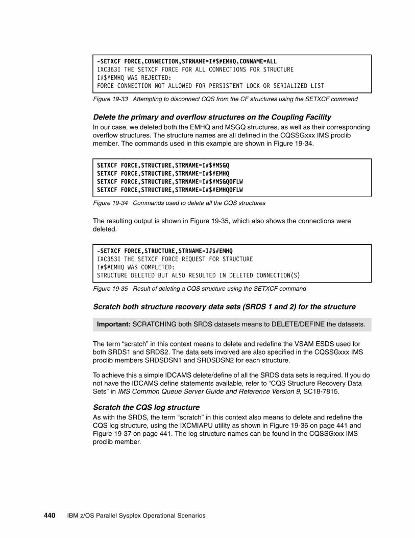
Figure 19-33 Attempting to disconnect CQS from the CF structures using the SETXCF command
Delete the primary and overflow structures on the Coupling FacilityIn our case, we deleted both the EMHQ and MSGQ structures, as well as their corresponding overflow structures. The structure names are all defined in the CQSSGxxx IMS proclib member. The commands used in this example are shown in Figure 19-34.
Figure 19-34 Commands used to delete all the CQS structures
The resulting output is shown in Figure 19-35, which also shows the connections were deleted.
Figure 19-35 Result of deleting a CQS structure using the SETXCF command
Scratch both structure recovery data sets (SRDS 1 and 2) for the structure
The term “scratch” in this context means to delete and redefine the VSAM ESDS used for both SRDS1 and SRDS2. The data sets involved are also specified in the CQSSGxxx IMS proclib members SRDSDSN1 and SRDSDSN2 for each structure.
To achieve this a simple IDCAMS delete/define of all the SRDS data sets is required. If you do not have the IDCAMS define statements available, refer to “CQS Structure Recovery Data Sets” in IMS Common Queue Server Guide and Reference Version 9, SC18-7815.
Scratch the CQS log structureAs with the SRDS, the term “scratch” in this context also means to delete and redefine the CQS log structure, using the IXCMIAPU utility as shown in Figure 19-36 on page 441 and Figure 19-37 on page 441. The log structure names can be found in the CQSSGxxx IMS proclib member.
-SETXCF FORCE,CONNECTION,STRNAME=I#$#EMHQ,CONNAME=ALLIXC363I THE SETXCF FORCE FOR ALL CONNECTIONS FOR STRUCTURE I#$#EMHQ WAS REJECTED: FORCE CONNECTION NOT ALLOWED FOR PERSISTENT LOCK OR SERIALIZED LIST
SETXCF FORCE,STRUCTURE,STRNAME=I#$#MSGQSETXCF FORCE,STRUCTURE,STRNAME=I#$#EMHQSETXCF FORCE,STRUCTURE,STRNAME=I#$#MSGQOFLWSETXCF FORCE,STRUCTURE,STRNAME=I#$#EMHQOFLW
-SETXCF FORCE,STRUCTURE,STRNAME=I#$#EMHQIXC353I THE SETXCF FORCE REQUEST FOR STRUCTURE I#$#EMHQ WAS COMPLETED: STRUCTURE DELETED BUT ALSO RESULTED IN DELETED CONNECTION(S)
Important: SCRATCHING both SRDS datasets means to DELETE/DEFINE the datasets.
440 IBM z/OS Parallel Sysplex Operational Scenarios
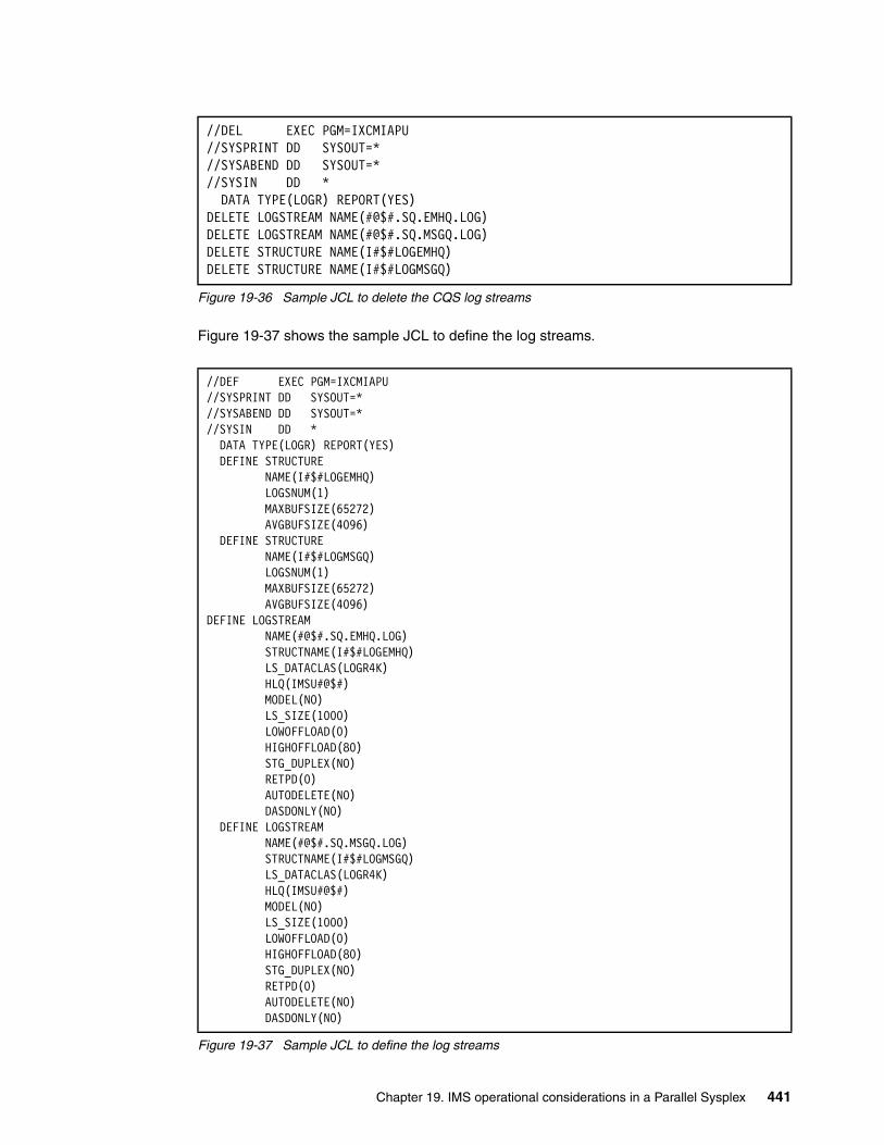
Figure 19-36 Sample JCL to delete the CQS log streams
Figure 19-37 shows the sample JCL to define the log streams.
Figure 19-37 Sample JCL to define the log streams
//DEL EXEC PGM=IXCMIAPU //SYSPRINT DD SYSOUT=* //SYSABEND DD SYSOUT=* //SYSIN DD * DATA TYPE(LOGR) REPORT(YES) DELETE LOGSTREAM NAME(#@$#.SQ.EMHQ.LOG) DELETE LOGSTREAM NAME(#@$#.SQ.MSGQ.LOG) DELETE STRUCTURE NAME(I#$#LOGEMHQ) DELETE STRUCTURE NAME(I#$#LOGMSGQ)
//DEF EXEC PGM=IXCMIAPU //SYSPRINT DD SYSOUT=* //SYSABEND DD SYSOUT=* //SYSIN DD * DATA TYPE(LOGR) REPORT(YES) DEFINE STRUCTURE NAME(I#$#LOGEMHQ) LOGSNUM(1) MAXBUFSIZE(65272) AVGBUFSIZE(4096) DEFINE STRUCTURE NAME(I#$#LOGMSGQ) LOGSNUM(1) MAXBUFSIZE(65272) AVGBUFSIZE(4096) DEFINE LOGSTREAM NAME(#@$#.SQ.EMHQ.LOG) STRUCTNAME(I#$#LOGEMHQ) LS_DATACLAS(LOGR4K) HLQ(IMSU#@$#) MODEL(NO) LS_SIZE(1000) LOWOFFLOAD(0) HIGHOFFLOAD(80) STG_DUPLEX(NO) RETPD(0) AUTODELETE(NO) DASDONLY(NO) DEFINE LOGSTREAM NAME(#@$#.SQ.MSGQ.LOG) STRUCTNAME(I#$#LOGMSGQ) LS_DATACLAS(LOGR4K) HLQ(IMSU#@$#) MODEL(NO) LS_SIZE(1000) LOWOFFLOAD(0) HIGHOFFLOAD(80) STG_DUPLEX(NO) RETPD(0) AUTODELETE(NO) DASDONLY(NO)
Chapter 19. IMS operational considerations in a Parallel Sysplex 441
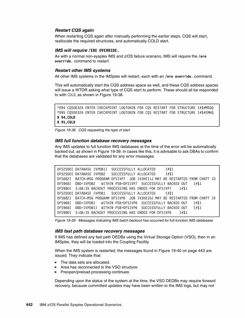
Restart CQS againWhen restarting CQS again after manually performing the earlier steps, CQS will start, reallocate the required structures, and automatically COLD start.
IMS will require /ERE OVERRIDE.As with a normal non-sysplex IMS and z/OS failure scenario, IMS will require the /ere override. command to restart.
Restart other IMS systemsAll other IMS systems in the IMSplex will restart, each with an /ere override. command.
This will automatically start the CQS address space as well, and these CQS address spaces will issue a WTOR asking what type of CQS start to perform. These should all be responded to with COLD, as shown in Figure 19-38.
Figure 19-38 CQS requesting the type of start
IMS full function database recovery messagesAny IMS updates to full function IMS databases at the time of the error will be automatically backed out, as shown in Figure 19-39. In cases like this, it is advisable to ask DBAs to confirm that the databases are validated for any error messages.
Figure 19-39 Messages indicating IMS batch backout has occurred for full function IMS databases
IMS fast path database recovery messagesIf IMS has defined any fast path DEDBs using the Virtual Storage Option (VSO), then in an IMSplex, they will be loaded into the Coupling Facility.
When the IMS system is restarted, the messages found in Figure 19-40 on page 443 are issued. They indicate that:
� The data sets are allocated.� Area has reconnected to the VSO structure.� Preopen/preload processing continues.
Depending upon the status of the system at the time, the VSO DEDBs may require forward recovery, because committed updates may have been written to the IMS logs, but may not
*094 CQS0032A ENTER CHECKPOINT LOGTOKEN FOR CQS RESTART FOR STRUCTURE I#$#MSGQ*095 CQS0032A ENTER CHECKPOINT LOGTOKEN FOR CQS RESTART FOR STRUCTURE I#$#EMHQR 94,COLDR 95,COLD
DFS2500I DATABASE IVPDB1I SUCCESSFULLY ALLOCATED I#$1 DFS2500I DATABASE IVPDB2 SUCCESSFULLY ALLOCATED I#$1 DFS682I BATCH-MSG PROGRAM DFSIVP7 JOB IV3H211J MAY BE RESTARTED FROM CHKPT IDDFS968I DBD=IVPDB2 WITHIN PSB=DFSIVP7 SUCCESSFULLY BACKED OUT I#$1 DFS980I 3:08:35 BACKOUT PROCESSING HAS ENDED FOR DFSIVP7 I#$1 DFS2500I DATABASE IVPDB1 SUCCESSFULLY ALLOCATED I#$1 DFS682I BATCH-MSG PROGRAM DFSIVP6 JOB IV3H210J MAY BE RESTARTED FROM CHKPT IDDFS968I DBD=IVPDB1 WITHIN PSB=DFSIVP6 SUCCESSFULLY BACKED OUT I#$1 DFS968I DBD=IVPDB1I WITHIN PSB=DFSIVP6 SUCCESSFULLY BACKED OUT I#$1 DFS980I 3:08:35 BACKOUT PROCESSING HAS ENDED FOR DFSIVP6 I#$1
442 IBM z/OS Parallel Sysplex Operational Scenarios
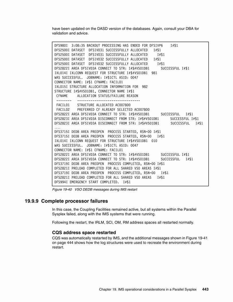
have been updated on the DASD version of the databases. Again, consult your DBA for validation and advice.
Figure 19-40 VSO DEDB messages during IMS restart
19.9.9 Complete processor failures
In this case, the Coupling Facilities remained active, but all systems within the Parallel Sysplex failed, along with the IMS systems that were running.
Following the restart, the IRLM, SCI, OM, RM address spaces all restarted normally.
CQS address space restarted CQS was automatically restarted by IMS, and the additional messages shown in Figure 19-41 on page 444 shows how the log structures were used to recreate the environment during restart.
DFS980I 3:08:35 BACKOUT PROCESSING HAS ENDED FOR DFSIVP6 I#$1 DFS2500I DATASET DFSIVD31 SUCCESSFULLY ALLOCATED I#$1 DFS2500I DATASET DFSIVD31 SUCCESSFULLY ALLOCATED I#$1 DFS2500I DATASET DFSIVD32 SUCCESSFULLY ALLOCATED I#$1 DFS2500I DATASET DFSIVD32 SUCCESSFULLY ALLOCATED I#$1 DFS2822I AREA DFSIVD3A CONNECT TO STR: I#$#VSO1DB1 SUCCESSFUL I#$1 IXL014I IXLCONN REQUEST FOR STRUCTURE I#$#VSO1DB1 981 WAS SUCCESSFUL. JOBNAME: I#$1CTL ASID: 0047 CONNECTOR NAME: I#$1 CFNAME: FACIL01 IXL015I STRUCTURE ALLOCATION INFORMATION FOR 982 STRUCTURE I#$#VSO1DB1, CONNECTOR NAME I#$1 CFNAME ALLOCATION STATUS/FAILURE REASON -------- --------------------------------- FACIL01 STRUCTURE ALLOCATED AC007800 FACIL02 PREFERRED CF ALREADY SELECTED AC007800 DFS2822I AREA DFSIVD3A CONNECT TO STR: I#$#VSO1DB1 SUCCESSFUL I#$1 DFS2823I AREA DFSIVD3A DISCONNECT FROM STR: I#$#VSO1DB1 SUCCESSFUL I#$1 DFS2823I AREA DFSIVD3A DISCONNECT FROM STR: I#$#VSO1DB1 SUCCESSFUL I#$1....DFS3715I DEDB AREA PREOPEN PROCESS STARTED, RSN=00 I#$1 DFS3715I DEDB AREA PREOPEN PROCESS STARTED, RSN=00 I#$1 IXL014I IXLCONN REQUEST FOR STRUCTURE I#$#VSO1DB1 010 WAS SUCCESSFUL. JOBNAME: I#$1CTL ASID: 0047 CONNECTOR NAME: I#$1 CFNAME: FACIL01 DFS2822I AREA DFSIVD3A CONNECT TO STR: I#$#VSO1DB1 SUCCESSFUL I#$1 DFS2822I AREA DFSIVD3A CONNECT TO STR: I#$#VSO1DB1 SUCCESSFUL I#$1 DFS3719I DEDB AREA PREOPEN PROCESS COMPLETED, RSN=00 I#$1 DFS2821I PRELOAD COMPLETED FOR ALL SHARED VSO AREAS I#$1 DFS3719I DEDB AREA PREOPEN PROCESS COMPLETED, RSN=00 I#$1 DFS2821I PRELOAD COMPLETED FOR ALL SHARED VSO AREAS I#$1 DFS994I EMERGENCY START COMPLETED. I#$1
Chapter 19. IMS operational considerations in a Parallel Sysplex 443
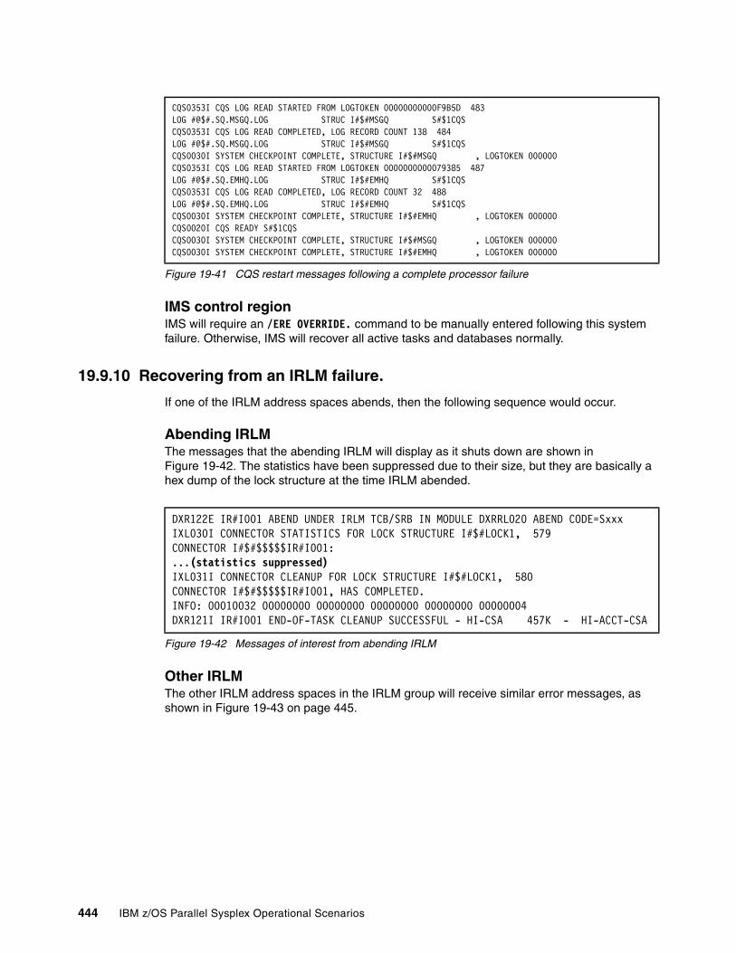
Figure 19-41 CQS restart messages following a complete processor failure
IMS control regionIMS will require an /ERE OVERRIDE. command to be manually entered following this system failure. Otherwise, IMS will recover all active tasks and databases normally.
19.9.10 Recovering from an IRLM failure.
If one of the IRLM address spaces abends, then the following sequence would occur.
Abending IRLM The messages that the abending IRLM will display as it shuts down are shown in Figure 19-42. The statistics have been suppressed due to their size, but they are basically a hex dump of the lock structure at the time IRLM abended.
Figure 19-42 Messages of interest from abending IRLM
Other IRLMThe other IRLM address spaces in the IRLM group will receive similar error messages, as shown in Figure 19-43 on page 445.
CQS0353I CQS LOG READ STARTED FROM LOGTOKEN 00000000000F9B5D 483 LOG #@$#.SQ.MSGQ.LOG STRUC I#$#MSGQ S#$1CQS CQS0353I CQS LOG READ COMPLETED, LOG RECORD COUNT 138 484 LOG #@$#.SQ.MSGQ.LOG STRUC I#$#MSGQ S#$1CQS CQS0030I SYSTEM CHECKPOINT COMPLETE, STRUCTURE I#$#MSGQ , LOGTOKEN 000000CQS0353I CQS LOG READ STARTED FROM LOGTOKEN 0000000000079385 487 LOG #@$#.SQ.EMHQ.LOG STRUC I#$#EMHQ S#$1CQS CQS0353I CQS LOG READ COMPLETED, LOG RECORD COUNT 32 488 LOG #@$#.SQ.EMHQ.LOG STRUC I#$#EMHQ S#$1CQS CQS0030I SYSTEM CHECKPOINT COMPLETE, STRUCTURE I#$#EMHQ , LOGTOKEN 000000CQS0020I CQS READY S#$1CQS CQS0030I SYSTEM CHECKPOINT COMPLETE, STRUCTURE I#$#MSGQ , LOGTOKEN 000000CQS0030I SYSTEM CHECKPOINT COMPLETE, STRUCTURE I#$#EMHQ , LOGTOKEN 000000
DXR122E IR#I001 ABEND UNDER IRLM TCB/SRB IN MODULE DXRRL020 ABEND CODE=Sxxx IXL030I CONNECTOR STATISTICS FOR LOCK STRUCTURE I#$#LOCK1, 579 CONNECTOR I#$#$$$$$IR#I001: ...(statistics suppressed)IXL031I CONNECTOR CLEANUP FOR LOCK STRUCTURE I#$#LOCK1, 580 CONNECTOR I#$#$$$$$IR#I001, HAS COMPLETED. INFO: 00010032 00000000 00000000 00000000 00000000 00000004 DXR121I IR#I001 END-OF-TASK CLEANUP SUCCESSFUL - HI-CSA 457K - HI-ACCT-CSA
444 IBM z/OS Parallel Sysplex Operational Scenarios
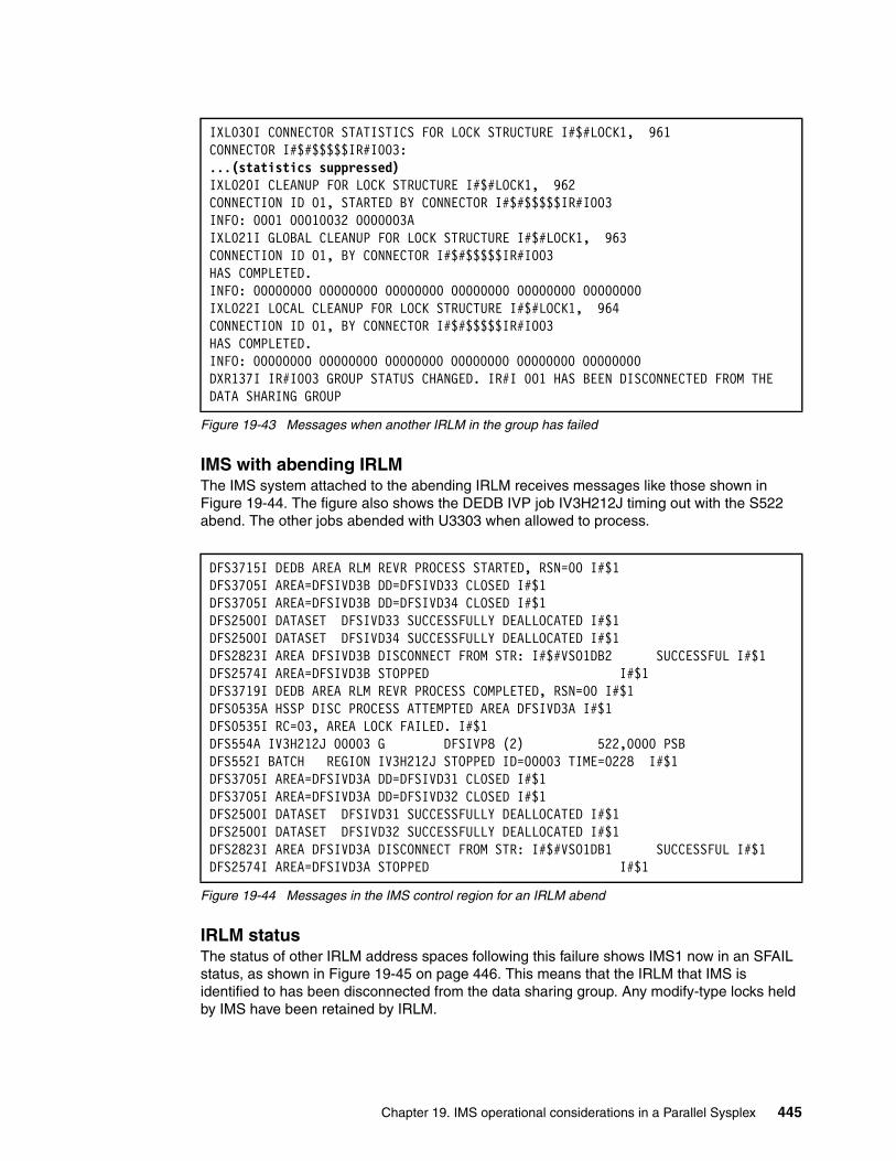
Figure 19-43 Messages when another IRLM in the group has failed
IMS with abending IRLMThe IMS system attached to the abending IRLM receives messages like those shown in Figure 19-44. The figure also shows the DEDB IVP job IV3H212J timing out with the S522 abend. The other jobs abended with U3303 when allowed to process.
Figure 19-44 Messages in the IMS control region for an IRLM abend
IRLM statusThe status of other IRLM address spaces following this failure shows IMS1 now in an SFAIL status, as shown in Figure 19-45 on page 446. This means that the IRLM that IMS is identified to has been disconnected from the data sharing group. Any modify-type locks held by IMS have been retained by IRLM.
IXL030I CONNECTOR STATISTICS FOR LOCK STRUCTURE I#$#LOCK1, 961CONNECTOR I#$#$$$$$IR#I003: ...(statistics suppressed)IXL020I CLEANUP FOR LOCK STRUCTURE I#$#LOCK1, 962 CONNECTION ID 01, STARTED BY CONNECTOR I#$#$$$$$IR#I003 INFO: 0001 00010032 0000003A IXL021I GLOBAL CLEANUP FOR LOCK STRUCTURE I#$#LOCK1, 963 CONNECTION ID 01, BY CONNECTOR I#$#$$$$$IR#I003 HAS COMPLETED. INFO: 00000000 00000000 00000000 00000000 00000000 00000000 IXL022I LOCAL CLEANUP FOR LOCK STRUCTURE I#$#LOCK1, 964 CONNECTION ID 01, BY CONNECTOR I#$#$$$$$IR#I003 HAS COMPLETED. INFO: 00000000 00000000 00000000 00000000 00000000 00000000 DXR137I IR#I003 GROUP STATUS CHANGED. IR#I 001 HAS BEEN DISCONNECTED FROM THE DATA SHARING GROUP
DFS3715I DEDB AREA RLM REVR PROCESS STARTED, RSN=00 I#$1 DFS3705I AREA=DFSIVD3B DD=DFSIVD33 CLOSED I#$1 DFS3705I AREA=DFSIVD3B DD=DFSIVD34 CLOSED I#$1 DFS2500I DATASET DFSIVD33 SUCCESSFULLY DEALLOCATED I#$1 DFS2500I DATASET DFSIVD34 SUCCESSFULLY DEALLOCATED I#$1 DFS2823I AREA DFSIVD3B DISCONNECT FROM STR: I#$#VSO1DB2 SUCCESSFUL I#$1 DFS2574I AREA=DFSIVD3B STOPPED I#$1 DFS3719I DEDB AREA RLM REVR PROCESS COMPLETED, RSN=00 I#$1 DFS0535A HSSP DISC PROCESS ATTEMPTED AREA DFSIVD3A I#$1 DFS0535I RC=03, AREA LOCK FAILED. I#$1 DFS554A IV3H212J 00003 G DFSIVP8 (2) 522,0000 PSB DFS552I BATCH REGION IV3H212J STOPPED ID=00003 TIME=0228 I#$1 DFS3705I AREA=DFSIVD3A DD=DFSIVD31 CLOSED I#$1 DFS3705I AREA=DFSIVD3A DD=DFSIVD32 CLOSED I#$1 DFS2500I DATASET DFSIVD31 SUCCESSFULLY DEALLOCATED I#$1 DFS2500I DATASET DFSIVD32 SUCCESSFULLY DEALLOCATED I#$1 DFS2823I AREA DFSIVD3A DISCONNECT FROM STR: I#$#VSO1DB1 SUCCESSFUL I#$1 DFS2574I AREA=DFSIVD3A STOPPED I#$1
Chapter 19. IMS operational considerations in a Parallel Sysplex 445
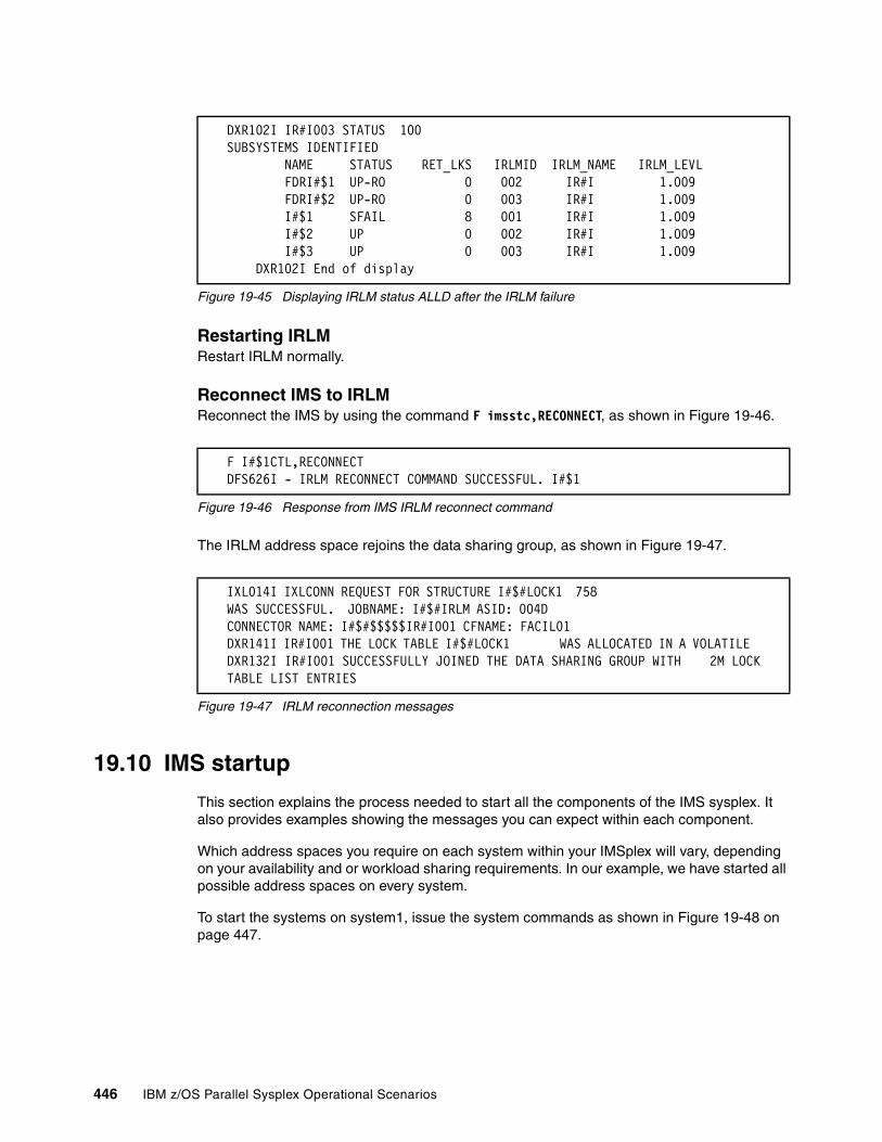
Figure 19-45 Displaying IRLM status ALLD after the IRLM failure
Restarting IRLMRestart IRLM normally.
Reconnect IMS to IRLMReconnect the IMS by using the command F imsstc,RECONNECT, as shown in Figure 19-46.
Figure 19-46 Response from IMS IRLM reconnect command
The IRLM address space rejoins the data sharing group, as shown in Figure 19-47.
Figure 19-47 IRLM reconnection messages
19.10 IMS startup
This section explains the process needed to start all the components of the IMS sysplex. It also provides examples showing the messages you can expect within each component.
Which address spaces you require on each system within your IMSplex will vary, depending on your availability and or workload sharing requirements. In our example, we have started all possible address spaces on every system.
To start the systems on system1, issue the system commands as shown in Figure 19-48 on page 447.
DXR102I IR#I003 STATUS 100 SUBSYSTEMS IDENTIFIED NAME STATUS RET_LKS IRLMID IRLM_NAME IRLM_LEVL FDRI#$1 UP-RO 0 002 IR#I 1.009 FDRI#$2 UP-RO 0 003 IR#I 1.009 I#$1 SFAIL 8 001 IR#I 1.009 I#$2 UP 0 002 IR#I 1.009 I#$3 UP 0 003 IR#I 1.009 DXR102I End of display
F I#$1CTL,RECONNECTDFS626I - IRLM RECONNECT COMMAND SUCCESSFUL. I#$1
IXL014I IXLCONN REQUEST FOR STRUCTURE I#$#LOCK1 758 WAS SUCCESSFUL. JOBNAME: I#$#IRLM ASID: 004D CONNECTOR NAME: I#$#$$$$$IR#I001 CFNAME: FACIL01 DXR141I IR#I001 THE LOCK TABLE I#$#LOCK1 WAS ALLOCATED IN A VOLATILE DXR132I IR#I001 SUCCESSFULLY JOINED THE DATA SHARING GROUP WITH 2M LOCK TABLE LIST ENTRIES
446 IBM z/OS Parallel Sysplex Operational Scenarios
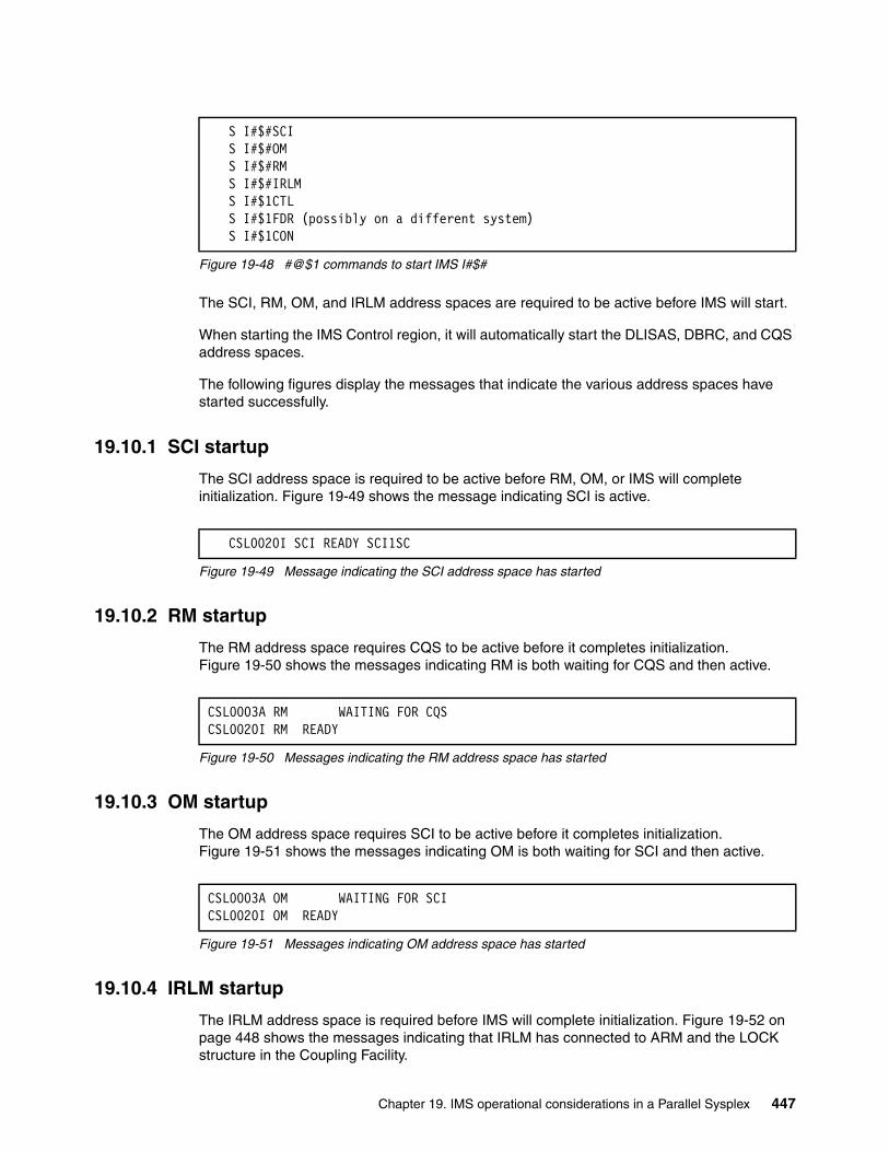
Figure 19-48 #@$1 commands to start IMS I#$#
The SCI, RM, OM, and IRLM address spaces are required to be active before IMS will start.
When starting the IMS Control region, it will automatically start the DLISAS, DBRC, and CQS address spaces.
The following figures display the messages that indicate the various address spaces have started successfully.
19.10.1 SCI startup
The SCI address space is required to be active before RM, OM, or IMS will complete initialization. Figure 19-49 shows the message indicating SCI is active.
Figure 19-49 Message indicating the SCI address space has started
19.10.2 RM startup
The RM address space requires CQS to be active before it completes initialization. Figure 19-50 shows the messages indicating RM is both waiting for CQS and then active.
Figure 19-50 Messages indicating the RM address space has started
19.10.3 OM startup
The OM address space requires SCI to be active before it completes initialization. Figure 19-51 shows the messages indicating OM is both waiting for SCI and then active.
Figure 19-51 Messages indicating OM address space has started
19.10.4 IRLM startup
The IRLM address space is required before IMS will complete initialization. Figure 19-52 on page 448 shows the messages indicating that IRLM has connected to ARM and the LOCK structure in the Coupling Facility.
S I#$#SCIS I#$#OMS I#$#RMS I#$#IRLMS I#$1CTLS I#$1FDR (possibly on a different system)S I#$1CON
CSL0020I SCI READY SCI1SC
CSL0003A RM WAITING FOR CQSCSL0020I RM READY
CSL0003A OM WAITING FOR SCI CSL0020I OM READY
Chapter 19. IMS operational considerations in a Parallel Sysplex 447
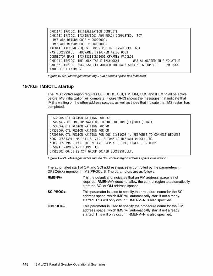
Figure 19-52 Messages indicating IRLM address space has initialized
19.10.5 IMSCTL startup
The IMS Control region requires DLI, DBRC, SCI, RM, OM, CQS and IRLM to all be active before IMS initialization will complete. Figure 19-53 shows the messages that indicate that IMS is waiting on the other address spaces, as well as those that indicate that IMS restart has completed.
Figure 19-53 Messages indicating the IMS control region address space initialization
The automated start of OM and SCI address spaces is controlled by the parameters in DFSCGxxx member in IMS.PROCLIB. The parameters are as follows:
RMENV= Y is the default and indicates that an RM address space is not required. RMENV=Y does not allow the control region to automatically start the SCI or OM address spaces.
SCIPROC= This parameter is used to specify the procedure name for the SCI address space, which IMS will automatically start if not already started. This will only occur if RMENV=N is also specified.
OMPROC= This parameter is used to specify the procedure name for the OM address space, which IMS will automatically start if not already started. This will only occur if RMENV=N is also specified.
DXR117I IR#I001 INITIALIZATION COMPLETE DXR172I IR#I001 I#$#IR#I001 ARM READY COMPLETED. 307 MVS ARM RETURN CODE = 00000000, MVS ARM REASON CODE = 00000000. IXL014I IXLCONN REQUEST FOR STRUCTURE I#$#LOCK1 654 WAS SUCCESSFUL. JOBNAME: I#$#IRLM ASID: 0053 CONNECTOR NAME: I#$#$$$$$IR#I001 CFNAME: FACIL02 DXR141I IR#I001 THE LOCK TABLE I#$#LOCK1 WAS ALLOCATED IN A VOLATILE DXR132I IR#I001 SUCCESSFULLY JOINED THE DATA SHARING GROUP WITH 2M LOCK TABLE LIST ENTRIES
DFS3306A CTL REGION WAITING FOR SCIDFS227A - CTL REGION WAITING FOR DLS REGION (I#$1DLI ) INITDFS3306A CTL REGION WAITING FOR RMDFS3306A CTL REGION WAITING FOR OMDFS0226A CTL REGION WAITING FOR CQS (I#$1CQS ), RESPONSE TO CONNECT REQUEST*002 DFS3139I IMS INITIALIZED, AUTOMATIC RESTART PROCEEDING*003 DFS039A IR#I NOT ACTIVE. REPLY RETRY, CANCEL, OR DUMP.DFS994I WARM START COMPLETEDDFS2360I 00:01:22 XCF GROUP JOINED SUCCESSFULLY.
448 IBM z/OS Parallel Sysplex Operational Scenarios

19.10.6 DLISAS startup
The DLISAS address space is automatically started by IMS (and is required even without an IMS sysplex). Figure 19-54 shows the DLISAS initialization messages, as well as the allocation and connections to the OSAM and VSAM structures in the Coupling Facility.
Figure 19-54 Messages indicating DLISAS has initialized
19.10.7 DBRC startup
The DBRC address space is automatically started by IMS (and is required even without an IMS sysplex). Figure 19-55 shows the message indicating that DBRC has completed initialization.
Figure 19-55 Messages indicating DBRC has initialized
Attention: In Figure 19-53, the region waiting messages for SCI, RM, OM, and CQS are not highlighted and could be lost with all the other messages produced at IMS startup, but as soon as these address spaces are active, IMS will continue automatically.
If the DFS039A message waiting on IRLM WTOR appears, then operations or automation will have to respond RETRY to the message before IMS will continue.
If an IMS automatic (AUTO=Y) restart is done, then the IMS WTOR DFS3139I will appear. As soon as this is used, then the IMS WTOR DFS996I *IMS READY* message will appear. If an IMS manual (AUTO=N) restart is done, then only the IMS WTOR DFS996A message will appear.
DFS228I - DLS RECALL TCB INITIALIZATION COMPLETE I#$1 DFS228I - DLS REGION STORAGE COMPRESSION INITIALIZED I#$1 DFS228I - DLS REGION DYNAMIC ALLOCATION INITIALIZED I#$1 DFS3386I OSAM CF CACHING RATIO= 050:001, 2 I#$1 IXL014I IXLCONN REQUEST FOR STRUCTURE I#$#OSAM 558 WAS SUCCESSFUL. JOBNAME: I#$1DLI ASID: 0055 CONNECTOR NAME: IXCLO0180001 CFNAME: FACIL02 IXL015I STRUCTURE ALLOCATION INFORMATION FOR 559 STRUCTURE I#$#OSAM, CONNECTOR NAME IXCLO0180001 CFNAME ALLOCATION STATUS/FAILURE REASON -------- --------------------------------- FACIL02 STRUCTURE ALLOCATED CC007800 FACIL01 PREFERRED CF ALREADY SELECTED CC007800 IXL014I IXLCONN REQUEST FOR STRUCTURE I#$#VSAM 565 WAS SUCCESSFUL. JOBNAME: I#$1DLI ASID: 0055 CONNECTOR NAME: IXCLO0170001 CFNAME: FACIL02 IXL015I STRUCTURE ALLOCATION INFORMATION FOR 566 STRUCTURE I#$#VSAM, CONNECTOR NAME IXCLO0170001 CFNAME ALLOCATION STATUS/FAILURE REASON -------- --------------------------------- FACIL02 STRUCTURE ALLOCATED CC007800 FACIL01 PREFERRED CF ALREADY SELECTED CC007800 DFS3382I DL/I CF INITIALIZATION COMPLETE I#$1 DFS228I - DLS REGION INITIALIZATION COMPLETE I#$1 DFS2500I DATABASE DI21PART SUCCESSFULLY ALLOCATED I#$1
DFS3613I - DRC TCB INITIALIZATION COMPLETE
Chapter 19. IMS operational considerations in a Parallel Sysplex 449
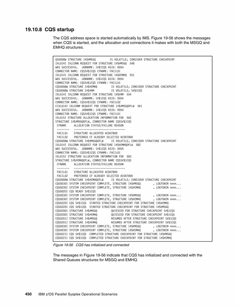
19.10.8 CQS startup
The CQS address space is started automatically by IMS. Figure 19-56 shows the messages when CQS is started, and the allocation and connections it makes with both the MSGQ and EMHQ structures.
Figure 19-56 CQS has initialized and connected
The messages in Figure 19-56 indicate that CQS has initialized and connected with the Shared Queues structures for MSGQ and EMHQ.
QS0008W STRUCTURE I#$#MSGQ IS VOLATILE; CONSIDER STRUCTURE CHECKPOINT IXL014I IXLCONN REQUEST FOR STRUCTURE I#$#MSGQ 548 WAS SUCCESSFUL. JOBNAME: I#$1CQS ASID: 0054 CONNECTOR NAME: CQSS#$1CQS CFNAME: FACIL01 IXL014I IXLCONN REQUEST FOR STRUCTURE I#$#EMHQ 551 WAS SUCCESSFUL. JOBNAME: I#$1CQS ASID: 0054 CONNECTOR NAME: CQSS#$1CQS CFNAME: FACIL01 CQS0008W STRUCTURE I#$#EMHQ IS VOLATILE; CONSIDER STRUCTURE CHECKPOINT CQS0008W STRUCTURE I#$#RM IS VOLATILE; S#$1CQS IXL014I IXLCONN REQUEST FOR STRUCTURE I#$#RM 554 WAS SUCCESSFUL. JOBNAME: I#$1CQS ASID: 0054 CONNECTOR NAME: CQSS#$1CQS CFNAME: FACIL02 CIXL014I IXLCONN REQUEST FOR STRUCTURE I#$#MSGQOFLW 561 WAS SUCCESSFUL. JOBNAME: I#$1CQS ASID: 0054 CONNECTOR NAME: CQSS#$1CQS CFNAME: FACIL01 IXL015I STRUCTURE ALLOCATION INFORMATION FOR 562 STRUCTURE I#$#MSGQOFLW, CONNECTOR NAME CQSS#$1CQS CFNAME ALLOCATION STATUS/FAILURE REASON -------- --------------------------------- FACIL01 STRUCTURE ALLOCATED AC007800 FACIL02 PREFERRED CF ALREADY SELECTED AC007800 CQS0008W STRUCTURE I#$#MSGQOFLW IS VOLATILE; CONSIDER STRUCTURE CHECKPOINT IXL014I IXLCONN REQUEST FOR STRUCTURE I#$#EMHQOFLW 582 WAS SUCCESSFUL. JOBNAME: I#$1CQS ASID: 0054 CONNECTOR NAME: CQSS#$1CQS CFNAME: FACIL01 IXL015I STRUCTURE ALLOCATION INFORMATION FOR 583 STRUCTURE I#$#EMHQOFLW, CONNECTOR NAME CQSS#$1CQS CFNAME ALLOCATION STATUS/FAILURE REASON -------- --------------------------------- FACIL01 STRUCTURE ALLOCATED AC007800 FACIL02 PREFERRED CF ALREADY SELECTED AC007800 CQS0008W STRUCTURE I#$#EMHQOFLW IS VOLATILE; CONSIDER STRUCTURE CHECKPOINT CQS0030I SYSTEM CHECKPOINT COMPLETE, STRUCTURE I#$#MSGQ , LOGTOKEN nnnn...CQS0030I SYSTEM CHECKPOINT COMPLETE, STRUCTURE I#$#EMHQ , LOGTOKEN nnnn...CQS0020I CQS READY S#$1CQS CQS0030I SYSTEM CHECKPOINT COMPLETE, STRUCTURE I#$#MSGQ , LOGTOKEN nnnn...CQS0030I SYSTEM CHECKPOINT COMPLETE, STRUCTURE I#$#EMHQ , LOGTOKEN nnnn...CQS0220I CQS S#$1CQS STARTED STRUCTURE CHECKPOINT FOR STRUCTURE I#$#EMHQ CQS0220I CQS S#$1CQS STARTED STRUCTURE CHECKPOINT FOR STRUCTURE I#$#MSGQ CQS0200I STRUCTURE I#$#MSGQ QUIESCED FOR STRUCTURE CHECKPOINT S#$1CQS CQS0200I STRUCTURE I#$#EMHQ QUIESCED FOR STRUCTURE CHECKPOINT S#$1CQS CQS0201I STRUCTURE I#$#MSGQ RESUMED AFTER STRUCTURE CHECKPOINT S#$1CQS CQS0201I STRUCTURE I#$#EMHQ RESUMED AFTER STRUCTURE CHECKPOINT S#$1CQS CQS0030I SYSTEM CHECKPOINT COMPLETE, STRUCTURE I#$#MSGQ , LOGTOKEN nnnn...CQS0030I SYSTEM CHECKPOINT COMPLETE, STRUCTURE I#$#EMHQ , LOGTOKEN nnnn...CQS0221I CQS S#$1CQS COMPLETED STRUCTURE CHECKPOINT FOR STRUCTURE I#$#MSGQ CQS0221I CQS S#$1CQS COMPLETED STRUCTURE CHECKPOINT FOR STRUCTURE I#$#EMHQ
450 IBM z/OS Parallel Sysplex Operational Scenarios
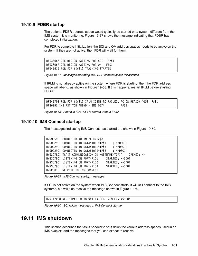
19.10.9 FDBR startup
The optional FDBR address space would typically be started on a system different from the IMS system it is monitoring. Figure 19-57 shows the message indicating that FDBR has completed initialization.
For FDR to complete initialization, the SCI and OM address spaces needs to be active on the system. If they are not active, then FDR will wait for them.
Figure 19-57 Messages indicating the FDBR address space initialization
If IRLM is not already active on the system where FDR is starting, then the FDR address space will abend, as shown in Figure 19-58. If this happens, restart IRLM before starting FDBR.
Figure 19-58 Abend in FDBR if it is started without IRLM
19.10.10 IMS Connect startup
The messages indicating IMS Connect has started are shown in Figure 19-59.
Figure 19-59 IMS Connect startup messages
If SCI is not active on the system when IMS Connect starts, it will still connect to the IMS systems, but will also receive the message shown in Figure 19-60.
Figure 19-60 SCI failure messages at IMS Connect startup
19.11 IMS shutdown
This section describes the tasks needed to shut down the various address spaces used in an IMS sysplex, and the messages that you can expect to receive.
DFS3306A CTL REGION WAITING FOR SCI - F#$1DFS3306A CTL REGION WAITING FOR OM - F#$1DFS4161I FDR FOR (I#$1) TRACKING STARTED
DFS4179E FDR FOR (I#$1) IRLM IDENT-RO FAILED, RC=08 REASON=4008 F#$1 DFS629I IMS RST TCB ABEND - IMS 0574 F#$1
HWSM0590I CONNECTED TO IMSPLEX=I#$# HWSD0290I CONNECTED TO DATASTORE=I#$1 ; M=DSC1 HWSD0290I CONNECTED TO DATASTORE=I#$3 ; M=DSC1 HWSD0290I CONNECTED TO DATASTORE=I#$2 ; M=DSC1 HWSS0780I TCPIP COMMUNICATION ON HOSTNAME=TCPIP OPENED; M=HWSS0790I LISTENING ON PORT=7101 STARTED; M=SDOT HWSS0790I LISTENING ON PORT=7102 STARTED; M=SDOT HWSS0790I LISTENING ON PORT=7103 STARTED; M=SDOT HWSC0010I WELCOME TO IMS CONNECT!
HWSI1720W REGISTRATION TO SCI FAILED: MEMBER=I#$1CON
Chapter 19. IMS operational considerations in a Parallel Sysplex 451
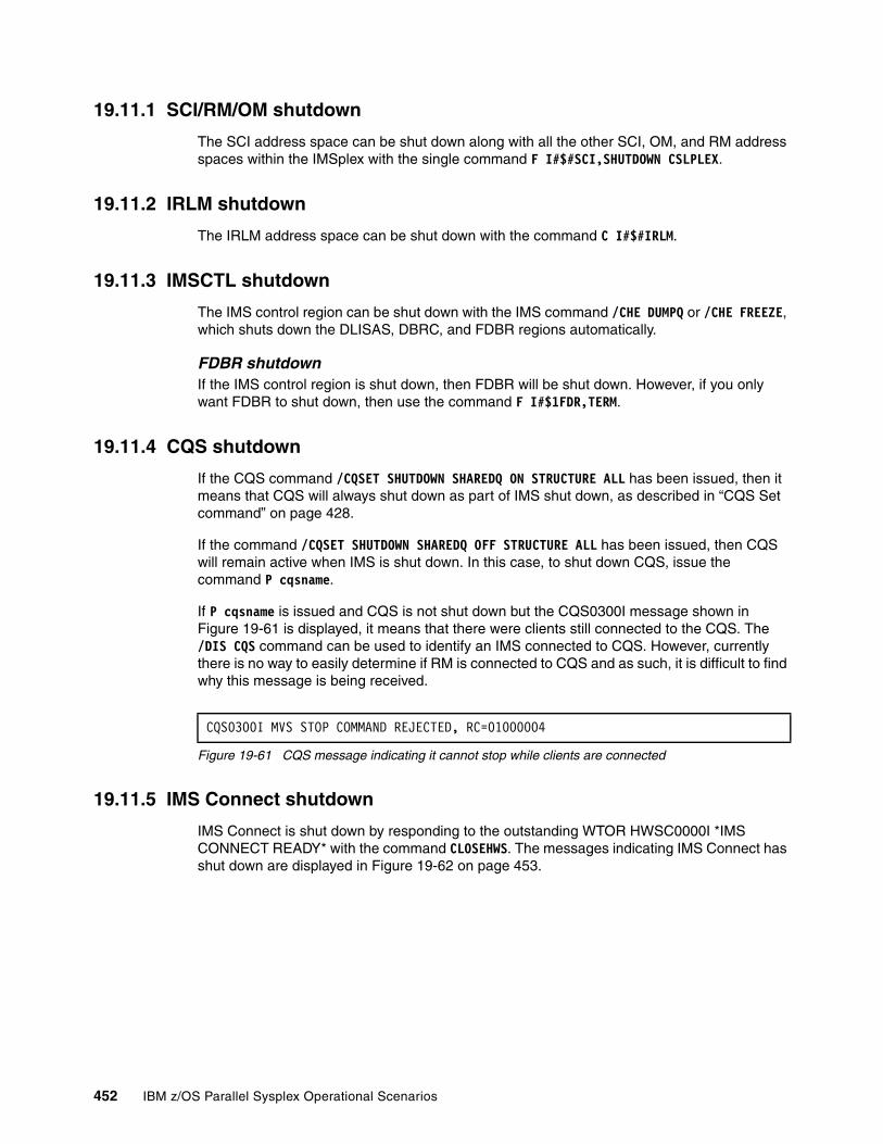
19.11.1 SCI/RM/OM shutdown
The SCI address space can be shut down along with all the other SCI, OM, and RM address spaces within the IMSplex with the single command F I#$#SCI,SHUTDOWN CSLPLEX.
19.11.2 IRLM shutdown
The IRLM address space can be shut down with the command C I#$#IRLM.
19.11.3 IMSCTL shutdown
The IMS control region can be shut down with the IMS command /CHE DUMPQ or /CHE FREEZE, which shuts down the DLISAS, DBRC, and FDBR regions automatically.
FDBR shutdownIf the IMS control region is shut down, then FDBR will be shut down. However, if you only want FDBR to shut down, then use the command F I#$1FDR,TERM.
19.11.4 CQS shutdown
If the CQS command /CQSET SHUTDOWN SHAREDQ ON STRUCTURE ALL has been issued, then it means that CQS will always shut down as part of IMS shut down, as described in “CQS Set command” on page 428.
If the command /CQSET SHUTDOWN SHAREDQ OFF STRUCTURE ALL has been issued, then CQS will remain active when IMS is shut down. In this case, to shut down CQS, issue the command P cqsname.
If P cqsname is issued and CQS is not shut down but the CQS0300I message shown in Figure 19-61 is displayed, it means that there were clients still connected to the CQS. The /DIS CQS command can be used to identify an IMS connected to CQS. However, currently there is no way to easily determine if RM is connected to CQS and as such, it is difficult to find why this message is being received.
Figure 19-61 CQS message indicating it cannot stop while clients are connected
19.11.5 IMS Connect shutdown
IMS Connect is shut down by responding to the outstanding WTOR HWSC0000I *IMS CONNECT READY* with the command CLOSEHWS. The messages indicating IMS Connect has shut down are displayed in Figure 19-62 on page 453.
CQS0300I MVS STOP COMMAND REJECTED, RC=01000004
452 IBM z/OS Parallel Sysplex Operational Scenarios
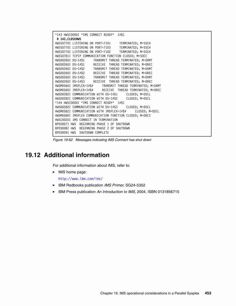
Figure 19-62 Messages indicating IMS Connect has shut down
19.12 Additional information
For additional information about IMS, refer to:
� IMS home page:
http://www.ibm.com/ims/
� IBM Redbooks publication IMS Primer, SG24-5352
� IBM Press publication An Introduction to IMS, 2004, ISBN 0131856715
*143 HWSC0000I *IMS CONNECT READY* I#$1 R 143,CLOSEHWS HWSS0770I LISTENING ON PORT=7101 TERMINATED; M=SSCH HWSS0770I LISTENING ON PORT=7103 TERMINATED; M=SSCH HWSS0770I LISTENING ON PORT=7102 TERMINATED; M=SSCH HWSS0781I TCPIP COMMUNICATION FUNCTION CLOSED; M=SOCC HWSD0260I DS=I#$1 TRANSMIT THREAD TERMINATED; M=DXMT HWSD0260I DS=I#$1 RECEIVE THREAD TERMINATED; M=DREC HWSD0260I DS=I#$2 TRANSMIT THREAD TERMINATED; M=DXMT HWSD0260I DS=I#$2 RECEIVE THREAD TERMINATED; M=DREC HWSD0260I DS=I#$3 TRANSMIT THREAD TERMINATED; M=DXMT HWSD0260I DS=I#$3 RECEIVE THREAD TERMINATED; M=DREC HWSM0560I IMSPLEX=I#$# TRANSMIT THREAD TERMINATED; M=OXMT HWSM0560I IMSPLEX=I#$# RECEIVE THREAD TERMINATED; M=OREC HWSD0282I COMMUNICATION WITH DS=I#$1 CLOSED; M=DSCL HWSD0282I COMMUNICATION WITH DS=I#$2 CLOSED; M=DSCL *144 HWSC0000I *IMS CONNECT READY* I#$1 HWSD0282I COMMUNICATION WITH DS=I#$3 CLOSED; M=DSCL HWSM0582I COMMUNICATION WITH IMSPLEX=I#$# CLOSED; M=DSCL HWSM0580I IMSPLEX COMMUNICATION FUNCTION CLOSED; M=DOC3 HWSC0020I IMS CONNECT IN TERMINATION BPE0007I HWS BEGINNING PHASE 1 OF SHUTDOWN BPE0008I HWS BEGINNING PHASE 2 OF SHUTDOWN BPE0009I HWS SHUTDOWN COMPLETE
Chapter 19. IMS operational considerations in a Parallel Sysplex 453

454 IBM z/OS Parallel Sysplex Operational Scenarios
Chapter 20. WebSphere MQ
This chapter provides an overview of various operational considerations to keep in mind when WebSphere MQ is implemented in a Parallel Sysplex.
20
© Copyright IBM Corp. 2009. All rights reserved. 455
20.1 Introduction to WebSphere MQ
WebSphere MQ is a subsystem used for the transport of data between applications. The applications communicate with each other and can be active on the same system, on different systems, or on different platforms altogether. This will be totally transparent to the application.
MQ transports the data between applications in the form of a message, which is a string of bytes meaningful to the application that uses it.
WebSphere MQ messages have two parts:
� Application data
The content and structure of the application data is defined by the application programs that use them.
� Message descriptor
The message descriptor identifies the message and contains additional control information, such as the type of message and the priority assigned to the message by the sending application.
When one application wants to send data to another application, it delivers the message to a part of MQ called a queue. A queue is a data structure used to store messages until they are retrieved by an application. The messages typically get removed from the queue when the receiving application asks the queue manager to receive a message from the named queue.
The queue manager owns and manages the set of resources that are used by WebSphere MQ, which includes:
� Page sets that hold the WebSphere MQ object definitions and message data
� Logs that are used to recover messages and objects in the event of queue manager failure
� Processor storage
� Connections through which different application environments such as CICS, IMS, and Batch can access the WebSphere MQ API
� The WebSphere MQ channel initiator, which allows communication between WebSphere MQ on your z/OS system and other systems
Figure 20-1 on page 457 shows the channel initiator and the queue manager with connections to different application environments.
456 IBM z/OS Parallel Sysplex Operational Scenarios
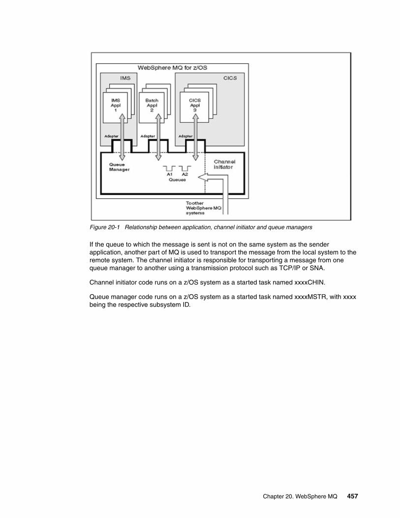
Figure 20-1 Relationship between application, channel initiator and queue managers
If the queue to which the message is sent is not on the same system as the sender application, another part of MQ is used to transport the message from the local system to the remote system. The channel initiator is responsible for transporting a message from one queue manager to another using a transmission protocol such as TCP/IP or SNA.
Channel initiator code runs on a z/OS system as a started task named xxxxCHIN.
Queue manager code runs on a z/OS system as a started task named xxxxMSTR, with xxxx being the respective subsystem ID.
Chapter 20. WebSphere MQ 457
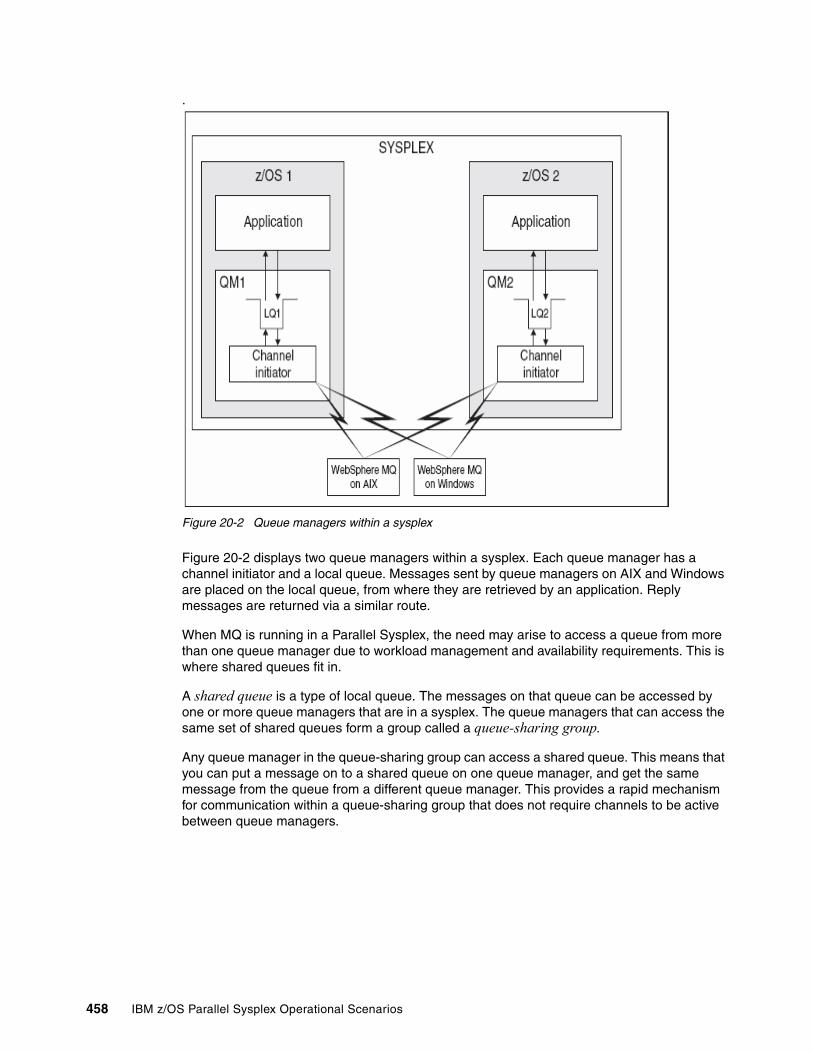
.
Figure 20-2 Queue managers within a sysplex
Figure 20-2 displays two queue managers within a sysplex. Each queue manager has a channel initiator and a local queue. Messages sent by queue managers on AIX and Windows are placed on the local queue, from where they are retrieved by an application. Reply messages are returned via a similar route.
When MQ is running in a Parallel Sysplex, the need may arise to access a queue from more than one queue manager due to workload management and availability requirements. This is where shared queues fit in.
A shared queue is a type of local queue. The messages on that queue can be accessed by one or more queue managers that are in a sysplex. The queue managers that can access the same set of shared queues form a group called a queue-sharing group.
Any queue manager in the queue-sharing group can access a shared queue. This means that you can put a message on to a shared queue on one queue manager, and get the same message from the queue from a different queue manager. This provides a rapid mechanism for communication within a queue-sharing group that does not require channels to be active between queue managers.
458 IBM z/OS Parallel Sysplex Operational Scenarios
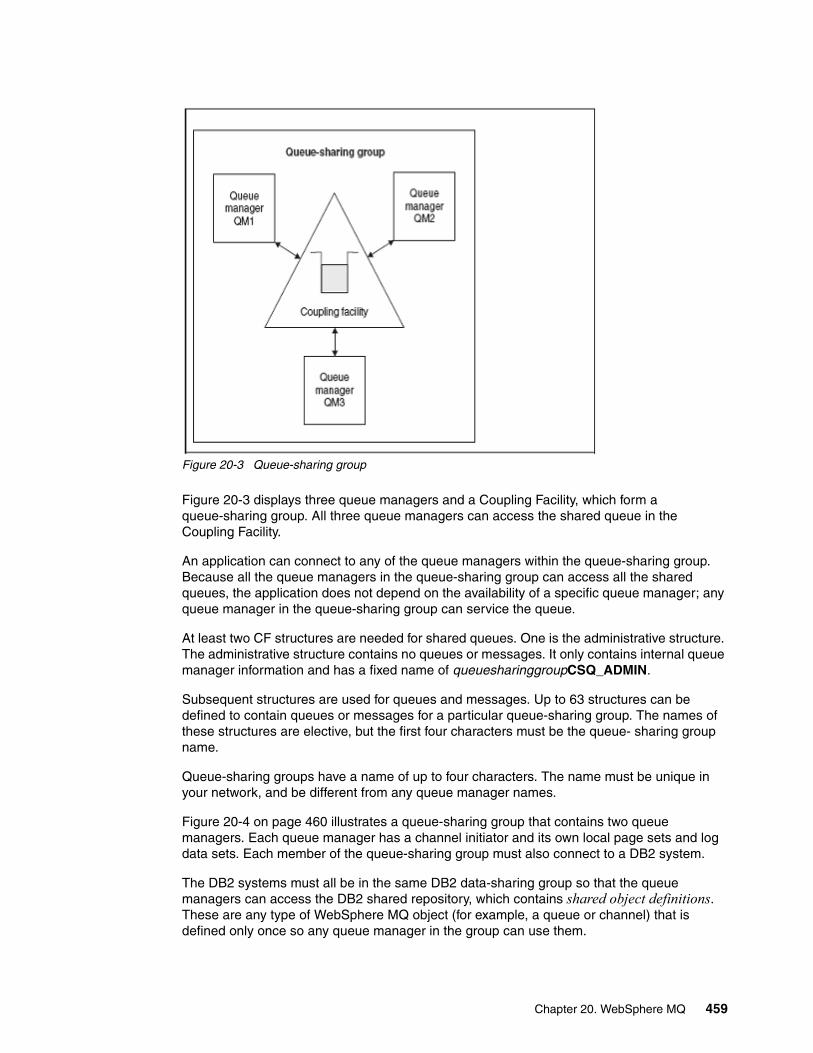
Figure 20-3 Queue-sharing group
Figure 20-3 displays three queue managers and a Coupling Facility, which form a queue-sharing group. All three queue managers can access the shared queue in the Coupling Facility.
An application can connect to any of the queue managers within the queue-sharing group. Because all the queue managers in the queue-sharing group can access all the shared queues, the application does not depend on the availability of a specific queue manager; any queue manager in the queue-sharing group can service the queue.
At least two CF structures are needed for shared queues. One is the administrative structure. The administrative structure contains no queues or messages. It only contains internal queue manager information and has a fixed name of queuesharinggroupCSQ_ADMIN.
Subsequent structures are used for queues and messages. Up to 63 structures can be defined to contain queues or messages for a particular queue-sharing group. The names of these structures are elective, but the first four characters must be the queue- sharing group name.
Queue-sharing groups have a name of up to four characters. The name must be unique in your network, and be different from any queue manager names.
Figure 20-4 on page 460 illustrates a queue-sharing group that contains two queue managers. Each queue manager has a channel initiator and its own local page sets and log data sets. Each member of the queue-sharing group must also connect to a DB2 system.
The DB2 systems must all be in the same DB2 data-sharing group so that the queue managers can access the DB2 shared repository, which contains shared object definitions. These are any type of WebSphere MQ object (for example, a queue or channel) that is defined only once so any queue manager in the group can use them.
Chapter 20. WebSphere MQ 459
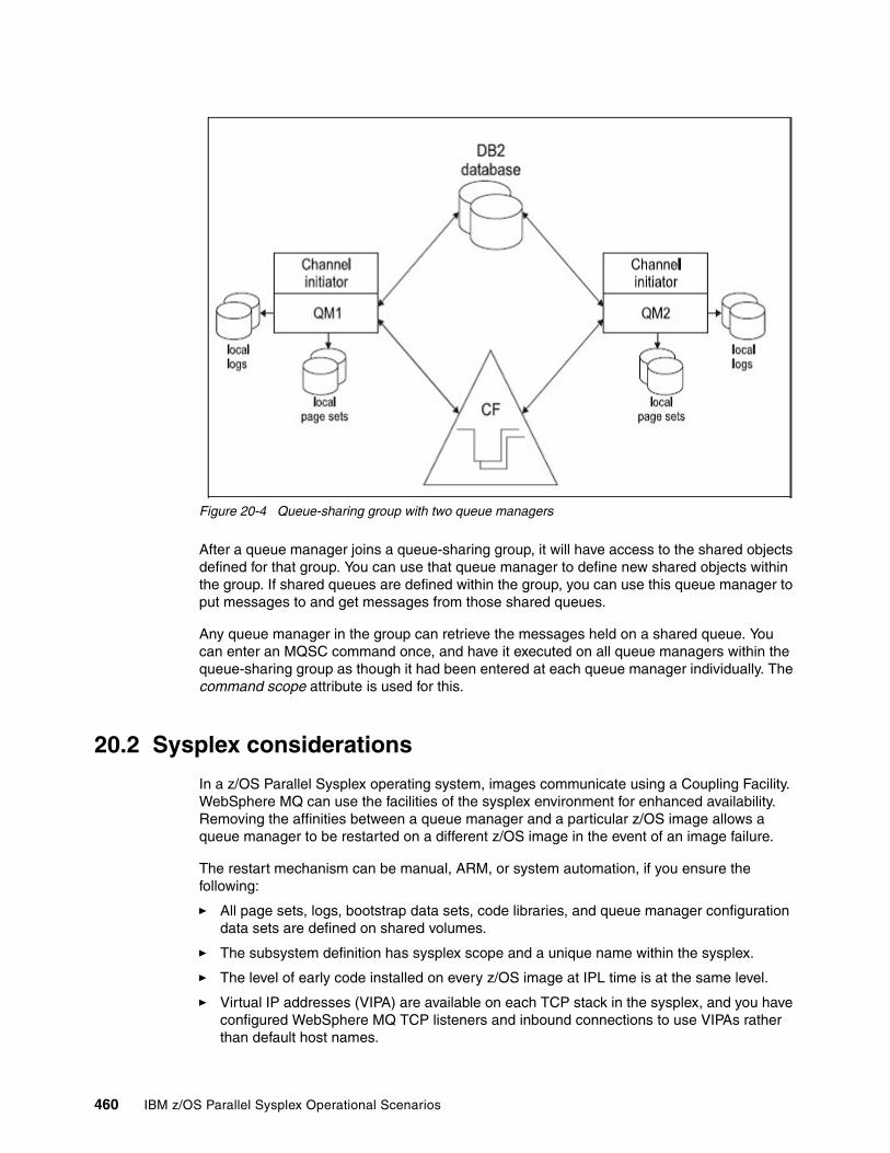
Figure 20-4 Queue-sharing group with two queue managers
After a queue manager joins a queue-sharing group, it will have access to the shared objects defined for that group. You can use that queue manager to define new shared objects within the group. If shared queues are defined within the group, you can use this queue manager to put messages to and get messages from those shared queues.
Any queue manager in the group can retrieve the messages held on a shared queue. You can enter an MQSC command once, and have it executed on all queue managers within the queue-sharing group as though it had been entered at each queue manager individually. The command scope attribute is used for this.
20.2 Sysplex considerations
In a z/OS Parallel Sysplex operating system, images communicate using a Coupling Facility. WebSphere MQ can use the facilities of the sysplex environment for enhanced availability. Removing the affinities between a queue manager and a particular z/OS image allows a queue manager to be restarted on a different z/OS image in the event of an image failure.
The restart mechanism can be manual, ARM, or system automation, if you ensure the following:
� All page sets, logs, bootstrap data sets, code libraries, and queue manager configuration data sets are defined on shared volumes.
� The subsystem definition has sysplex scope and a unique name within the sysplex.
� The level of early code installed on every z/OS image at IPL time is at the same level.
� Virtual IP addresses (VIPA) are available on each TCP stack in the sysplex, and you have configured WebSphere MQ TCP listeners and inbound connections to use VIPAs rather than default host names.
460 IBM z/OS Parallel Sysplex Operational Scenarios
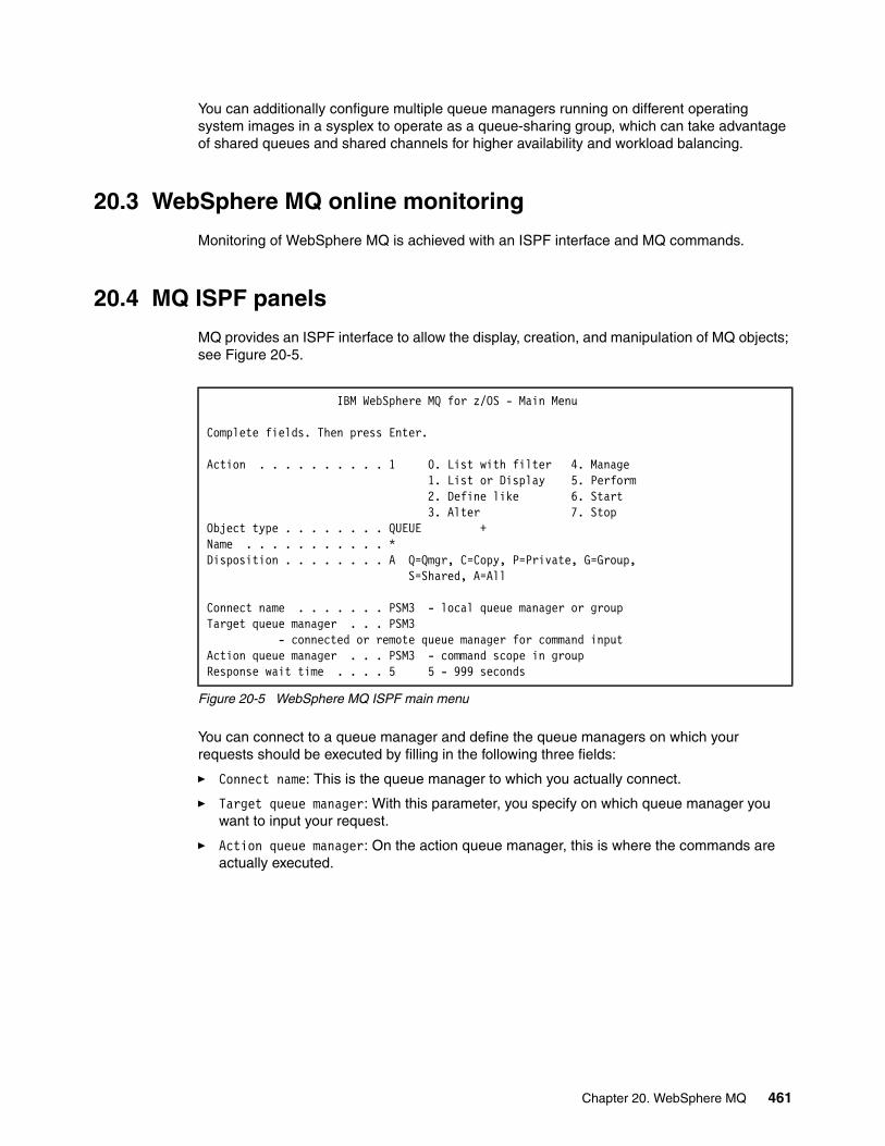
You can additionally configure multiple queue managers running on different operating system images in a sysplex to operate as a queue-sharing group, which can take advantage of shared queues and shared channels for higher availability and workload balancing.
20.3 WebSphere MQ online monitoring
Monitoring of WebSphere MQ is achieved with an ISPF interface and MQ commands.
20.4 MQ ISPF panels
MQ provides an ISPF interface to allow the display, creation, and manipulation of MQ objects; see Figure 20-5.
Figure 20-5 WebSphere MQ ISPF main menu
You can connect to a queue manager and define the queue managers on which your requests should be executed by filling in the following three fields:
� Connect name: This is the queue manager to which you actually connect.
� Target queue manager: With this parameter, you specify on which queue manager you want to input your request.
� Action queue manager: On the action queue manager, this is where the commands are actually executed.
IBM WebSphere MQ for z/OS - Main Menu Complete fields. Then press Enter. Action . . . . . . . . . . 1 0. List with filter 4. Manage 1. List or Display 5. Perform 2. Define like 6. Start 3. Alter 7. Stop Object type . . . . . . . . QUEUE + Name . . . . . . . . . . . * Disposition . . . . . . . . A Q=Qmgr, C=Copy, P=Private, G=Group, S=Shared, A=All Connect name . . . . . . . PSM3 - local queue manager or group Target queue manager . . . PSM3 - connected or remote queue manager for command input Action queue manager . . . PSM3 - command scope in group Response wait time . . . . 5 5 - 999 seconds
Chapter 20. WebSphere MQ 461

Figure 20-6 Display of WebSphere MQ objects and their disposition
20.4.1 WebSphere MQ commands
WebSphere MQ includes the following commands for monitoring the status of MQ objects. Use the appropriate MQ command prefix:
� Display the status of all channels
DISPLAY CHSTATUS(*)
The channel status displayed is RETRYING, which may suggest that the connection to the CF structure for our queues or messages for this particular queue-sharing group has failed.
Figure 20-7 Channel status display
List Queues - PSM3 Row 1 of 35 Type action codes, then press Enter. Press F11 to display queue status. 1=Display 2=Define like 3=Alter 4=Manage Name Type Disposition <> * QUEUE ALL PSM3 CICS01.INITQ QLOCAL QMGR PSM3 GROUP.QUEUE QLOCAL COPY PSM3 GROUP.QUEUE QLOCAL GROUP ISF.CLIENT.SDSF._/%3.REQUESTQ QALIAS QMGR PSM3 ISF.MODEL.QUEUE QMODEL QMGR PSM3 PSM1 QREMOTE QMGR PSM3 PSM1.XMITQ QLOCAL QMGR PSM3 PSM2 QREMOTE QMGR PSM3 PSM2.XMITQ QLOCAL QMGR PSM3 PSM3.DEAD.QUEUE QLOCAL QMGR PSM3 PSM3.DEFXMIT.QUEUE QLOCAL QMGR PSM3 PSM3.LOCAL.QUEUE QLOCAL QMGR PSM3 SHARED.QUEUE QLOCAL SHARED SYSTEM.ADMIN.CHANNEL.EVENT QLOCAL QMGR PSM3 SYSTEM.ADMIN.CONFIG.EVENT QLOCAL QMGR PSM3 SYSTEM.ADMIN.PERFM.EVENT QLOCAL QMGR PSM3
CSQM293I -PSM3 CSQMDRTC 1 CHSTATUS FOUND MATCHING REQUEST CRITERIA CSQM201I -PSM3 CSQMDRTC DIS CHSTATUS DETAILS CHSTATUS(TO.PSM2) CHLDISP(PRIVATE) XMITQ(SYSTEM.CLUSTER.TRANSMIT.QUEUE) CONNAME(PST2) CURRENT CHLTYPE(CLUSSDR) STATUS(RETRYING) SUBSTATE( ) STOPREQ(NO) RQMNAME( ) END CHSTATUS DETAILS CSQ9022I -PSM3 CSQMDRTC ' DIS CHSTATUS' NORMAL COMPLETION
462 IBM z/OS Parallel Sysplex Operational Scenarios
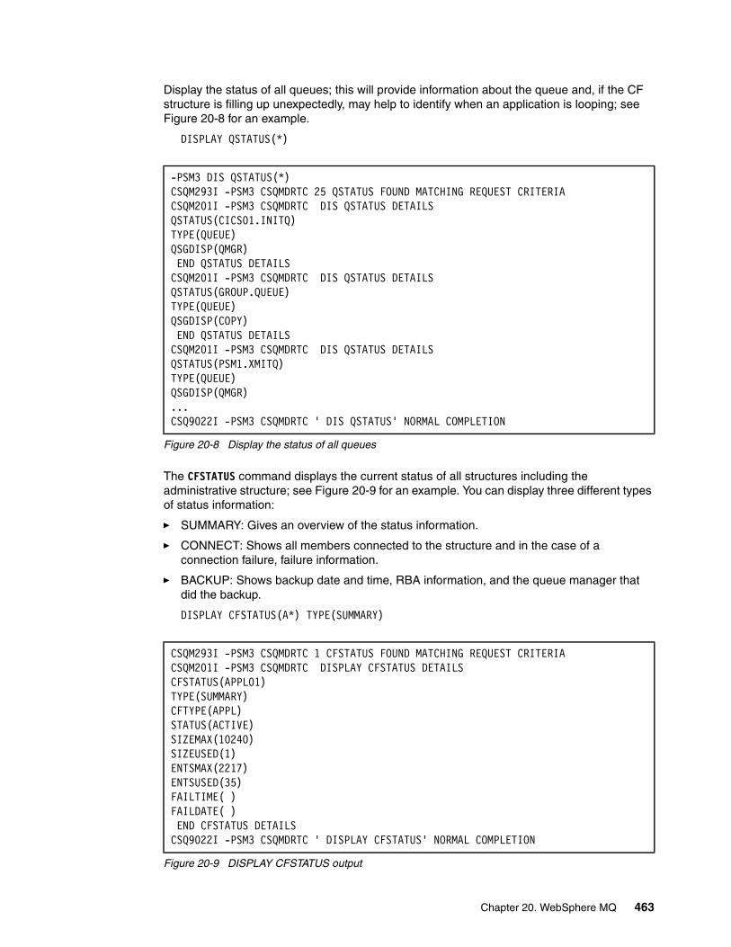
Display the status of all queues; this will provide information about the queue and, if the CF structure is filling up unexpectedly, may help to identify when an application is looping; see Figure 20-8 for an example.
DISPLAY QSTATUS(*)
Figure 20-8 Display the status of all queues
The CFSTATUS command displays the current status of all structures including the administrative structure; see Figure 20-9 for an example. You can display three different types of status information:
� SUMMARY: Gives an overview of the status information.
� CONNECT: Shows all members connected to the structure and in the case of a connection failure, failure information.
� BACKUP: Shows backup date and time, RBA information, and the queue manager that did the backup.
DISPLAY CFSTATUS(A*) TYPE(SUMMARY)
Figure 20-9 DISPLAY CFSTATUS output
-PSM3 DIS QSTATUS(*) CSQM293I -PSM3 CSQMDRTC 25 QSTATUS FOUND MATCHING REQUEST CRITERIA CSQM201I -PSM3 CSQMDRTC DIS QSTATUS DETAILS QSTATUS(CICS01.INITQ) TYPE(QUEUE) QSGDISP(QMGR) END QSTATUS DETAILS CSQM201I -PSM3 CSQMDRTC DIS QSTATUS DETAILS QSTATUS(GROUP.QUEUE) TYPE(QUEUE) QSGDISP(COPY) END QSTATUS DETAILS CSQM201I -PSM3 CSQMDRTC DIS QSTATUS DETAILS QSTATUS(PSM1.XMITQ) TYPE(QUEUE) QSGDISP(QMGR) ... CSQ9022I -PSM3 CSQMDRTC ' DIS QSTATUS' NORMAL COMPLETION
CSQM293I -PSM3 CSQMDRTC 1 CFSTATUS FOUND MATCHING REQUEST CRITERIACSQM201I -PSM3 CSQMDRTC DISPLAY CFSTATUS DETAILS CFSTATUS(APPL01) TYPE(SUMMARY) CFTYPE(APPL) STATUS(ACTIVE) SIZEMAX(10240) SIZEUSED(1) ENTSMAX(2217) ENTSUSED(35) FAILTIME( ) FAILDATE( ) END CFSTATUS DETAILS CSQ9022I -PSM3 CSQMDRTC ' DISPLAY CFSTATUS' NORMAL COMPLETION
Chapter 20. WebSphere MQ 463
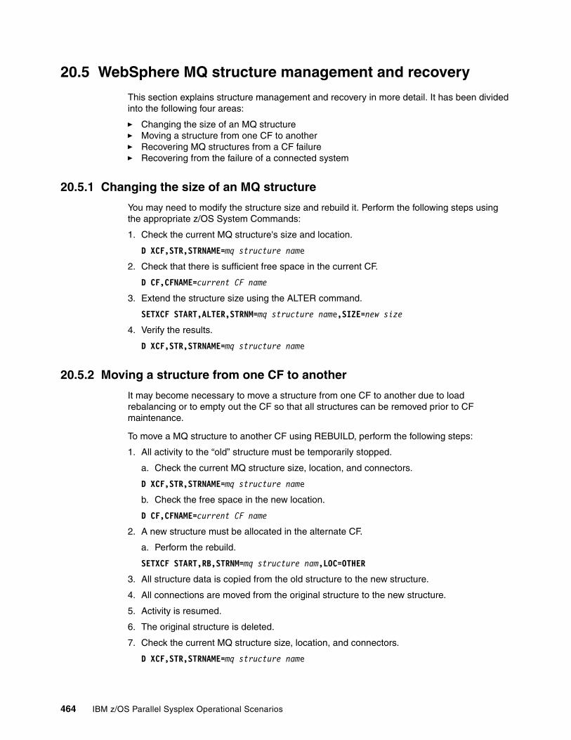
20.5 WebSphere MQ structure management and recovery
This section explains structure management and recovery in more detail. It has been divided into the following four areas:
� Changing the size of an MQ structure� Moving a structure from one CF to another� Recovering MQ structures from a CF failure � Recovering from the failure of a connected system
20.5.1 Changing the size of an MQ structure
You may need to modify the structure size and rebuild it. Perform the following steps using the appropriate z/OS System Commands:
1. Check the current MQ structure's size and location.
D XCF,STR,STRNAME=mq structure name
2. Check that there is sufficient free space in the current CF.
D CF,CFNAME=current CF name
3. Extend the structure size using the ALTER command.
SETXCF START,ALTER,STRNM=mq structure name,SIZE=new size
4. Verify the results.
D XCF,STR,STRNAME=mq structure name
20.5.2 Moving a structure from one CF to another
It may become necessary to move a structure from one CF to another due to load rebalancing or to empty out the CF so that all structures can be removed prior to CF maintenance.
To move a MQ structure to another CF using REBUILD, perform the following steps:
1. All activity to the “old” structure must be temporarily stopped.
a. Check the current MQ structure size, location, and connectors.
D XCF,STR,STRNAME=mq structure name
b. Check the free space in the new location.
D CF,CFNAME=current CF name
2. A new structure must be allocated in the alternate CF.
a. Perform the rebuild.
SETXCF START,RB,STRNM=mq structure nam,LOC=OTHER
3. All structure data is copied from the old structure to the new structure.
4. All connections are moved from the original structure to the new structure.
5. Activity is resumed.
6. The original structure is deleted.
7. Check the current MQ structure size, location, and connectors.
D XCF,STR,STRNAME=mq structure name
464 IBM z/OS Parallel Sysplex Operational Scenarios
MQ structure rebuilds should normally be performed when there is little or no MQ activity. The rebuild process is fully supported by MQ, but there is a brief period of time where access to the shared queues in the structure is denied.
20.5.3 Recovering MQ structures from a CF failure
Be prepared to recover in the event of a CF failure. All MQ queue managers will abend with code S5C6 and need to be restarted after the CF is made available again. This occurs if they lose connectivity because they are unable to detect if the other queue managers are still connected to the CF; it also ensures data integrity. Perform the following steps to recover from a CF failure:
1. Check the status of the MQ structure.
D XCF,STR,STRNAME=mq structure name
2. Check the status of the queue-sharing group from all the MQ systems using the appropriate MQ command prefix:
DIS QMGR,QSGNAME
3. Display CF storage and connectivity information.
D CF,CFNM=CF Name
D XCF,CF,CFNM=CF Name
4. Recover the CF.
5. Move all structures that normally reside there back into the CF.
SETXCF START,REALLOC
6. Start MQ again so that the queue managers can recover from the CF failure.
20.5.4 Recovering from the failure of a connected system
The following actions are required for MQ to recover from the failure of an image in a Parallel Sysplex. The CF structures will be unaffected by this outage but the surviving queue managers on other systems will perform recovery on behalf of the failing queue manager. Perform the following steps to recover MQ from a system outage:
1. Display the system status to ascertain the failing image.
D XCF,S,ALL
2. Check the status of the queue-sharing group from all the MQ systems using the appropriate MQ command prefix.
DIS QMGR,QSGNAME
3. Check the status of the MQ structure from any other system in the sysplex.
D XCF,STR,STRNAME=mq structure name
The number of connectors will have been reduced by 1.
4. IPL the failed image.
5. Start your DB2 subsystem, and then start WebSphere MQ. When MQ shared queues use DB2 tables, DB2 must be started first.
6. MQ will initiate recovery automatically.
Recommendation: Use system-managed duplexing on all MQ structures and thereby avoid system abends in the event of a loss of connectivity related to a single CF failure.
Chapter 20. WebSphere MQ 465

20.6 WebSphere MQ and Automatic Restart Manager
The Automatic Restart Manager (ARM) is a z/OS recovery function that can improve the availability of your WebSphere MQ queue managers. ARM improves the time required to reinstate a queue manager by automatically restarting the batch job or started task (referred to as an element) when it unexpectedly terminates. ARM preforms this without operator intervention.
If a queue manager or a channel initiator fails, ARM can restart it on the same LPAR. If z/OS fails, ARM can restart WebSphere MQ and any related subsystem automatically on another LPAR within the sysplex.
20.6.1 Verifying the successful registry at startup
Issue the following MVS command to obtain the current ARM status of an element:
D XCF,ARMS,JOBNAME=MQ STC,DETAIL
The results from this command display current statistics such as the first and last ARM restart time, and that the job is currently available for ARM restarts; see Figure 20-10.
Figure 20-10 ARMSTATUS DETAIL output
Only the queue manager should be restarted by ARM. The channel initiator should be restarted from CSQINP2 initialization data set. Set up your WebSphere MQ environment so that the channel initiator and associated listeners are started automatically when the queue manager is restarted.
For more detailed information about ARM, refer to Chapter 6, “Automatic Restart Manager” on page 83.
IXC392I 04.17.23 DISPLAY XCF 972 ARM RESTARTS ARE ENABLED -------------- ELEMENT STATE SUMMARY -------------- -TOTAL- -MAX- STARTING AVAILABLE FAILED RESTARTING RECOVERING 0 1 0 0 0 1 200 RESTART GROUP:DEFAULT PACING : 0 FREECSA: 0 0 ELEMENT NAME :SYSMQMGRPSM3 JOBNAME :PSM3MSTR STATE :AVAILABLE CURR SYS :#@$3 JOBTYPE :STC ASID :004C INIT SYS :#@$3 JESGROUP:XCFJES2A TERMTYPE:ALLTERM EVENTEXIT:*NONE* ELEMTYPE:SYSMQMGR LEVEL : 2 TOTAL RESTARTS : 0 INITIAL START:07/04/2007 23:43:35 RESTART THRESH : 0 OF 0 FIRST RESTART:*NONE* RESTART TIMEOUT: 300 LAST RESTART:*NONE*
466 IBM z/OS Parallel Sysplex Operational Scenarios
Chapter 21. Resource Recovery Services
This chapter introduces Resource Recovery Services (RRS) and provides an overview of operational considerations to keep in mind when it is implemented in a Parallel Sysplex.
21
© Copyright IBM Corp. 2009. All rights reserved. 467
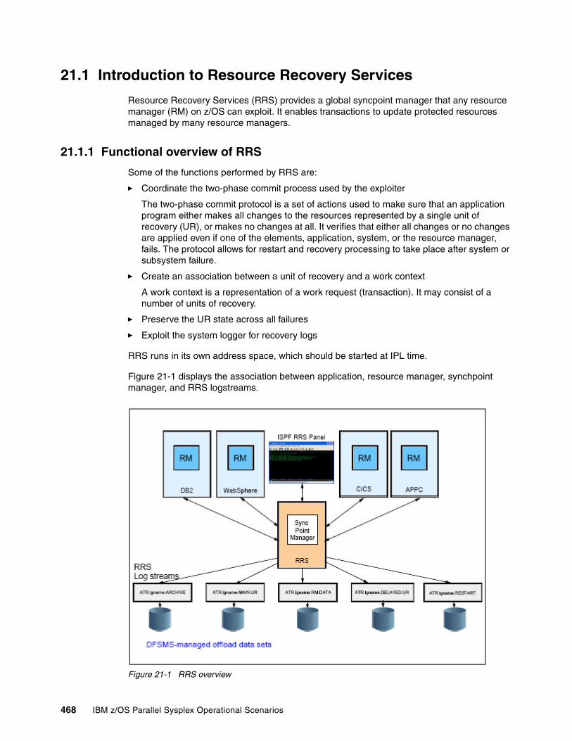
21.1 Introduction to Resource Recovery Services
Resource Recovery Services (RRS) provides a global syncpoint manager that any resource manager (RM) on z/OS can exploit. It enables transactions to update protected resources managed by many resource managers.
21.1.1 Functional overview of RRS
Some of the functions performed by RRS are:
� Coordinate the two-phase commit process used by the exploiter
The two-phase commit protocol is a set of actions used to make sure that an application program either makes all changes to the resources represented by a single unit of recovery (UR), or makes no changes at all. It verifies that either all changes or no changes are applied even if one of the elements, application, system, or the resource manager, fails. The protocol allows for restart and recovery processing to take place after system or subsystem failure.
� Create an association between a unit of recovery and a work context
A work context is a representation of a work request (transaction). It may consist of a number of units of recovery.
� Preserve the UR state across all failures
� Exploit the system logger for recovery logs
RRS runs in its own address space, which should be started at IPL time.
Figure 21-1 displays the association between application, resource manager, synchpoint manager, and RRS logstreams.
Figure 21-1 RRS overview
468 IBM z/OS Parallel Sysplex Operational Scenarios
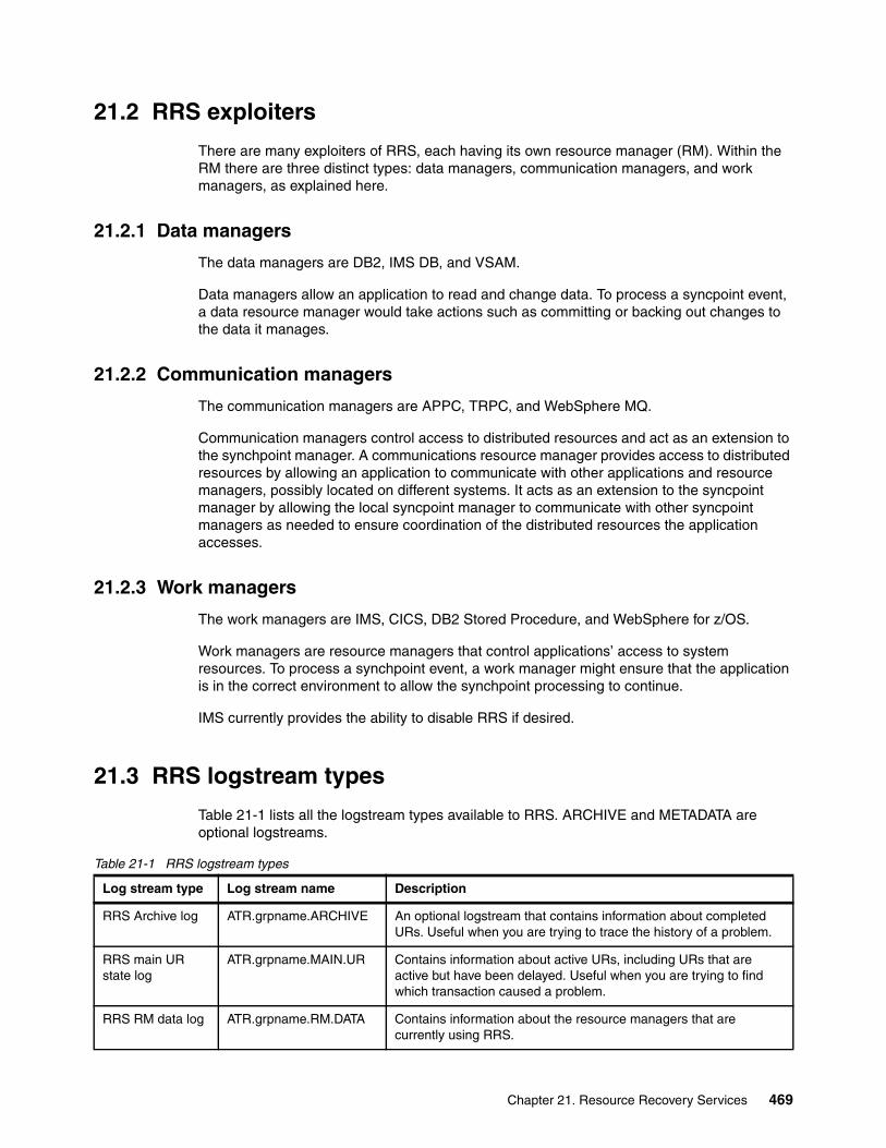
21.2 RRS exploiters
There are many exploiters of RRS, each having its own resource manager (RM). Within the RM there are three distinct types: data managers, communication managers, and work managers, as explained here.
21.2.1 Data managers
The data managers are DB2, IMS DB, and VSAM.
Data managers allow an application to read and change data. To process a syncpoint event, a data resource manager would take actions such as committing or backing out changes to the data it manages.
21.2.2 Communication managers
The communication managers are APPC, TRPC, and WebSphere MQ.
Communication managers control access to distributed resources and act as an extension to the synchpoint manager. A communications resource manager provides access to distributed resources by allowing an application to communicate with other applications and resource managers, possibly located on different systems. It acts as an extension to the syncpoint manager by allowing the local syncpoint manager to communicate with other syncpoint managers as needed to ensure coordination of the distributed resources the application accesses.
21.2.3 Work managers
The work managers are IMS, CICS, DB2 Stored Procedure, and WebSphere for z/OS.
Work managers are resource managers that control applications’ access to system resources. To process a synchpoint event, a work manager might ensure that the application is in the correct environment to allow the synchpoint processing to continue.
IMS currently provides the ability to disable RRS if desired.
21.3 RRS logstream types
Table 21-1 lists all the logstream types available to RRS. ARCHIVE and METADATA are optional logstreams.
Table 21-1 RRS logstream types
Log stream type Log stream name Description
RRS Archive log ATR.grpname.ARCHIVE An optional logstream that contains information about completed URs. Useful when you are trying to trace the history of a problem.
RRS main UR state log
ATR.grpname.MAIN.UR Contains information about active URs, including URs that are active but have been delayed. Useful when you are trying to find which transaction caused a problem.
RRS RM data log ATR.grpname.RM.DATA Contains information about the resource managers that are currently using RRS.
Chapter 21. Resource Recovery Services 469

If the ARCHIVE logstream is defined and write activity to the RRS ARCHIVE log stream is high, this may impact the performance throughput of all RRS transactions actively in use by RRS. This log stream is optional and only needed by the installation for any post-transaction history type of investigation. If you choose not to use the ARCHIVE log stream, a warning message is issued at RRS startup time about not being able to connect to the log stream, RRS, however, will continue its initialization process.
21.4 Starting RRS
To invokes the RRS procedure and create the RRS address space, issue the following system command:
START RRS,SUB=MSTR
If you have created a different procedure for starting RRS, then use that member name.There is a sample start procedure available in SYS1.SAMPLIB(ATRRRS).
Warm startThe normal mode of operation is a warm start. This occurs when valid data is found in the RM.DATA log stream. For RRS to access data about incomplete transactions, all defined RRS log streams should be intact. METADATA and ARCHIVE are optional log streams and do not need to be defined. Figure 21-2 on page 471 displays the messages you would expect after an RRS warm start.
RRS delayed UR state log
ATR.grpname.DELAYED.UR
Contains information about the state of active URs when UR completion is delayed.
RRS restart log ATR.grpname.RESTART Contains information about incomplete URs that resource managers might need after a system or RRS failure. Enables a functioning RRS instance to take over incomplete work left over from an RRS instance that failed.
RRS Metadata log ATR.grpname.METADATA An optional logstream that contains information created by a resource manager for its own use.
Log stream type Log stream name Description
470 IBM z/OS Parallel Sysplex Operational Scenarios
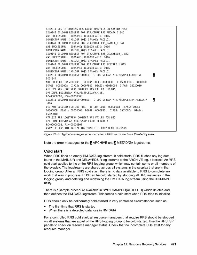
Figure 21-2 Typical messages produced after a RRS warm start in a Parallel Sysplex
Note the error messages for the 1 ARCHIVE and 2 METADATA logstreams.
Cold startWhen RRS finds an empty RM.DATA log stream, it cold starts. RRS flushes any log data found in the MAIN.UR and DELAYED.UR log streams to the ARCHIVE log, if it exists. An RRS cold start applies to the entire RRS logging group, which may contain some or all members of the sysplex. The logstreams are shared across all systems in the sysplex that are in that logging group. After an RRS cold start, there is no data available to RRS to complete any work that was in progress. RRS can be cold started by stopping all RRS instances in the logging group, and deleting and redefining the RM.DATA log stream using the IXCMIAPU utility.
There is a sample procedure available in SYS1.SAMPLIB(ATRCOLD) which deletes and then defines the RM.DATA logstream. This forces a cold start when RRS tries to initialize.
RRS should only be deliberately cold-started in very controlled circumstances such as:
� The first time that RRS is started� When there is a detected data loss in RM.DATA
For a controlled RRS cold start, all resource managers that require RRS should be stopped on all systems that are a part of the RRS logging group to be cold started. Use the RRS ISPF panels to check on resource manager status. Check that no incomplete URs exist for any resource manager.
ATR221I RRS IS JOINING RRS GROUP #@$#PLEX ON SYSTEM #@$3 IXL014I IXLCONN REQUEST FOR STRUCTURE RRS_RMDATA_1 840 WAS SUCCESSFUL. JOBNAME: IXGLOGR ASID: 0016 CONNECTOR NAME: IXGLOGR_#@$3 CFNAME: FACIL01 IXL014I IXLCONN REQUEST FOR STRUCTURE RRS_MAINUR_1 841 WAS SUCCESSFUL. JOBNAME: IXGLOGR ASID: 0016 CONNECTOR NAME: IXGLOGR_#@$3 CFNAME: FACIL01 IXL014I IXLCONN REQUEST FOR STRUCTURE RRS_DELAYEDUR_1 842 WAS SUCCESSFUL. JOBNAME: IXGLOGR ASID: 0016 CONNECTOR NAME: IXGLOGR_#@$3 CFNAME: FACIL01 IXL014I IXLCONN REQUEST FOR STRUCTURE RRS_RESTART_1 843 WAS SUCCESSFUL. JOBNAME: IXGLOGR ASID: 0016 CONNECTOR NAME: IXGLOGR_#@$3 CFNAME: FACIL01 IXG231I IXGCONN REQUEST=CONNECT TO LOG STREAM ATR.#@$#PLEX.ARCHIVE 1DID 844 NOT SUCCEED FOR JOB RRS. RETURN CODE: 00000008 REASON CODE: 0000080B DIAG1: 00000008 DIAG2: 0000F801 DIAG3: 05030004 DIAG4: 05020010 ATR132I RRS LOGSTREAM CONNECT HAS FAILED FOR 845 OPTIONAL LOGSTREAM ATR.#@$#PLEX.ARCHIVE. RC=00000008, RSN=0000080B IXG231I IXGCONN REQUEST=CONNECT TO LOG STREAM ATR.#@$#PLEX.RM.METADATA 2 846 DID NOT SUCCEED FOR JOB RRS. RETURN CODE: 00000008 REASON CODE: 0000080B DIAG1: 00000008 DIAG2: 0000F801 DIAG3: 05030004 DIAG4: 05020010 ATR132I RRS LOGSTREAM CONNECT HAS FAILED FOR 847 OPTIONAL LOGSTREAM ATR.#@$#PLEX.RM.METADATA. RC=00000008, RSN=0000080B ASA2011I RRS INITIALIZATION COMPLETE. COMPONENT ID=SCRRS
Chapter 21. Resource Recovery Services 471

21.5 Stopping RRS
Use these commands only at the direction of the system programmer. RRS should be running at all times. Stopping RRS can cause application programs to abend or wait until RRS is restarted.
� SETRRS CANCEL
This will terminate (abend) all incomplete commit and backout requests, then pass the return codes to the requesting application programs.
� SETRRS SHUTDOWN (available only with z/OS V1R8 and above)
This provides a normal shutdown command to bring down RRS without resulting in an X'058' abend. All the currently active resource managers will be unset. After the unset processing is completed, the RRS jobstep task and all of its subtasks will be normally terminated to clean up the address space.
In addition to the RRS infrastructure tasks, there are also timed process tasks and server tasks running in the RRS address space. These tasks will be shut down normally as well. Syncpoint processing for the outstanding work will be stopped by unsetting exits of the resource manager. The resource manager will need to reset its exits and restart with RRS upon restart.
21.6 Displaying the status of RRS
Using the D RRS,RM,S (available only with z/OS V1R8 and above) command, you can:
� Display all the RMs using RRS� Display their current state � Display the system they are operating on� Display the groupname in use
Figure 21-3 shows the output from the D RRS,RM,S command.
Figure 21-3 Output from D RRS,RM,S
The following system commands may assist in identifying delays within RRS.
� D RRS,UR,S (available only with z/OS V1R8 and above)
ATR602I 23.52.32 RRS RM SUMMARY 148 RM NAME STATE SYSTEM GNAME CSQ.RRSATF.IBM.PSM2 Reset #@$2 #@$#PLEXDFHRXDM.#@$CWE2A.IBM Reset #@$2 #@$#PLEXDFHRXDM.#@$C1A2A.IBM Reset #@$2 #@$#PLEXDFHRXDM.#@$C1T2A.IBM Reset #@$2 #@$#PLEXDSN.RRSATF.IBM.D#$2 Run #@$2 #@$#PLEXDSN.RRSPAS.IBM.D#$2 Run #@$2 #@$#PLEX
472 IBM z/OS Parallel Sysplex Operational Scenarios
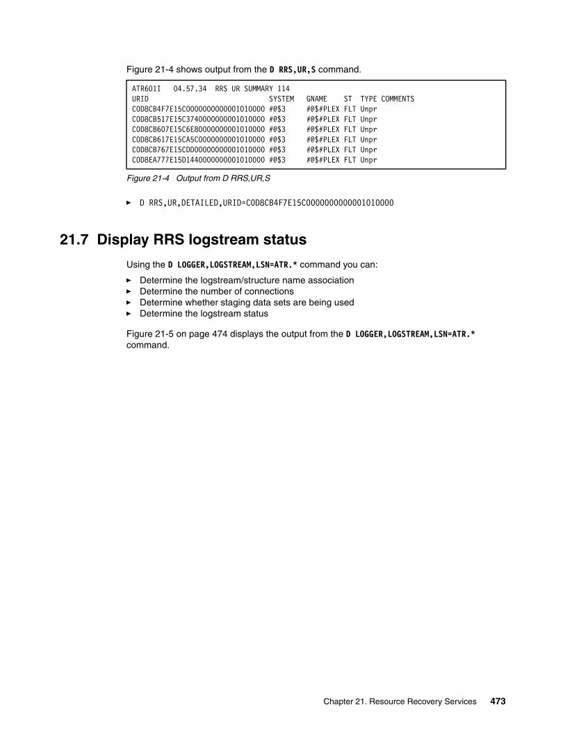
Figure 21-4 shows output from the D RRS,UR,S command.
Figure 21-4 Output from D RRS,UR,S
� D RRS,UR,DETAILED,URID=C0D8CB4F7E15C0000000000001010000
21.7 Display RRS logstream status
Using the D LOGGER,LOGSTREAM,LSN=ATR.* command you can:
� Determine the logstream/structure name association� Determine the number of connections� Determine whether staging data sets are being used� Determine the logstream status
Figure 21-5 on page 474 displays the output from the D LOGGER,LOGSTREAM,LSN=ATR.* command.
ATR601I 04.57.34 RRS UR SUMMARY 114 URID SYSTEM GNAME ST TYPE COMMENTSC0D8CB4F7E15C0000000000001010000 #@$3 #@$#PLEX FLT Unpr C0D8CB517E15C3740000000001010000 #@$3 #@$#PLEX FLT Unpr C0D8CB607E15C6E80000000001010000 #@$3 #@$#PLEX FLT Unpr C0D8CB617E15CA5C0000000001010000 #@$3 #@$#PLEX FLT Unpr C0D8CB767E15CDD00000000001010000 #@$3 #@$#PLEX FLT Unpr C0D8EA777E15D1440000000001010000 #@$3 #@$#PLEX FLT Unpr
Chapter 21. Resource Recovery Services 473
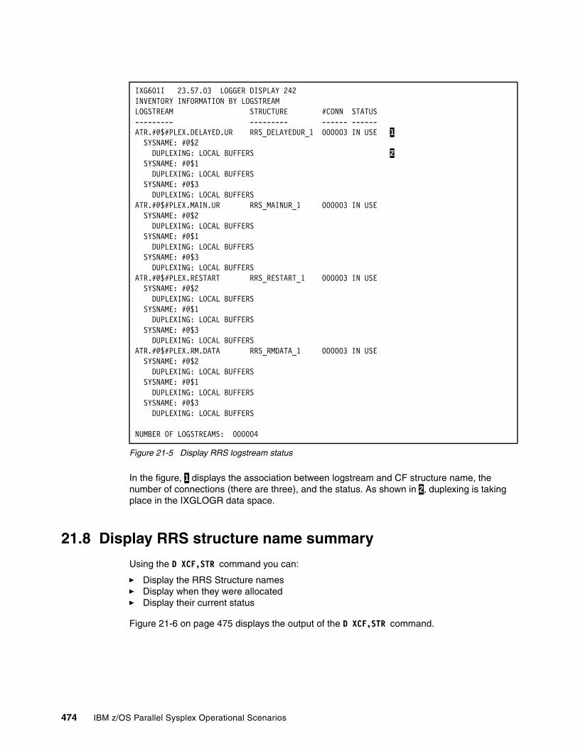
Figure 21-5 Display RRS logstream status
In the figure, 1 displays the association between logstream and CF structure name, the number of connections (there are three), and the status. As shown in 2, duplexing is taking place in the IXGLOGR data space.
21.8 Display RRS structure name summary
Using the D XCF,STR command you can:
� Display the RRS Structure names � Display when they were allocated� Display their current status
Figure 21-6 on page 475 displays the output of the D XCF,STR command.
IXG601I 23.57.03 LOGGER DISPLAY 242 INVENTORY INFORMATION BY LOGSTREAM LOGSTREAM STRUCTURE #CONN STATUS--------- --------- ------ ------ATR.#@$#PLEX.DELAYED.UR RRS_DELAYEDUR_1 000003 IN USE 1 SYSNAME: #@$2 DUPLEXING: LOCAL BUFFERS 2 SYSNAME: #@$1 DUPLEXING: LOCAL BUFFERS SYSNAME: #@$3 DUPLEXING: LOCAL BUFFERS ATR.#@$#PLEX.MAIN.UR RRS_MAINUR_1 000003 IN USE SYSNAME: #@$2 DUPLEXING: LOCAL BUFFERS SYSNAME: #@$1 DUPLEXING: LOCAL BUFFERS SYSNAME: #@$3 DUPLEXING: LOCAL BUFFERS ATR.#@$#PLEX.RESTART RRS_RESTART_1 000003 IN USE SYSNAME: #@$2 DUPLEXING: LOCAL BUFFERS SYSNAME: #@$1 DUPLEXING: LOCAL BUFFERS SYSNAME: #@$3 DUPLEXING: LOCAL BUFFERS ATR.#@$#PLEX.RM.DATA RRS_RMDATA_1 000003 IN USE SYSNAME: #@$2 DUPLEXING: LOCAL BUFFERS SYSNAME: #@$1 DUPLEXING: LOCAL BUFFERS SYSNAME: #@$3 DUPLEXING: LOCAL BUFFERS NUMBER OF LOGSTREAMS: 000004
474 IBM z/OS Parallel Sysplex Operational Scenarios
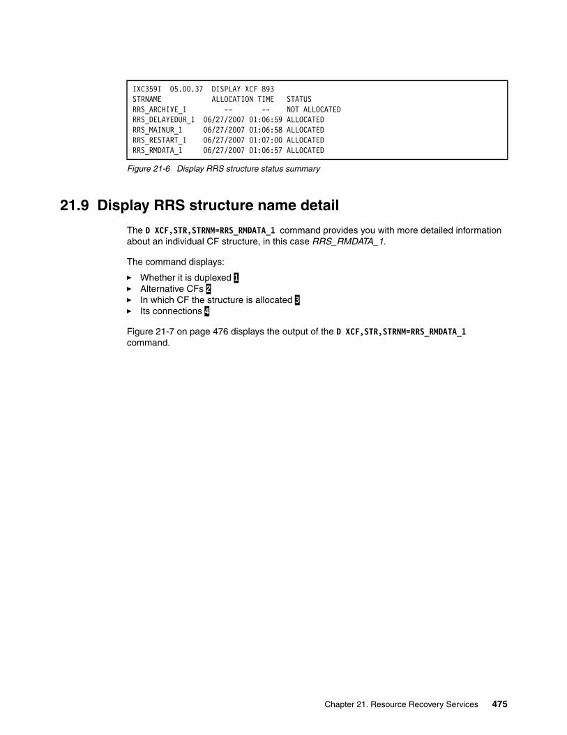
Figure 21-6 Display RRS structure status summary
21.9 Display RRS structure name detail
The D XCF,STR,STRNM=RRS_RMDATA_1 command provides you with more detailed information about an individual CF structure, in this case RRS_RMDATA_1.
The command displays:
� Whether it is duplexed 1� Alternative CFs 2 � In which CF the structure is allocated 3 � Its connections 4
Figure 21-7 on page 476 displays the output of the D XCF,STR,STRNM=RRS_RMDATA_1 command.
IXC359I 05.00.37 DISPLAY XCF 893 STRNAME ALLOCATION TIME STATUS RRS_ARCHIVE_1 -- -- NOT ALLOCATED RRS_DELAYEDUR_1 06/27/2007 01:06:59 ALLOCATED RRS_MAINUR_1 06/27/2007 01:06:58 ALLOCATED RRS_RESTART_1 06/27/2007 01:07:00 ALLOCATED RRS_RMDATA_1 06/27/2007 01:06:57 ALLOCATED
Chapter 21. Resource Recovery Services 475
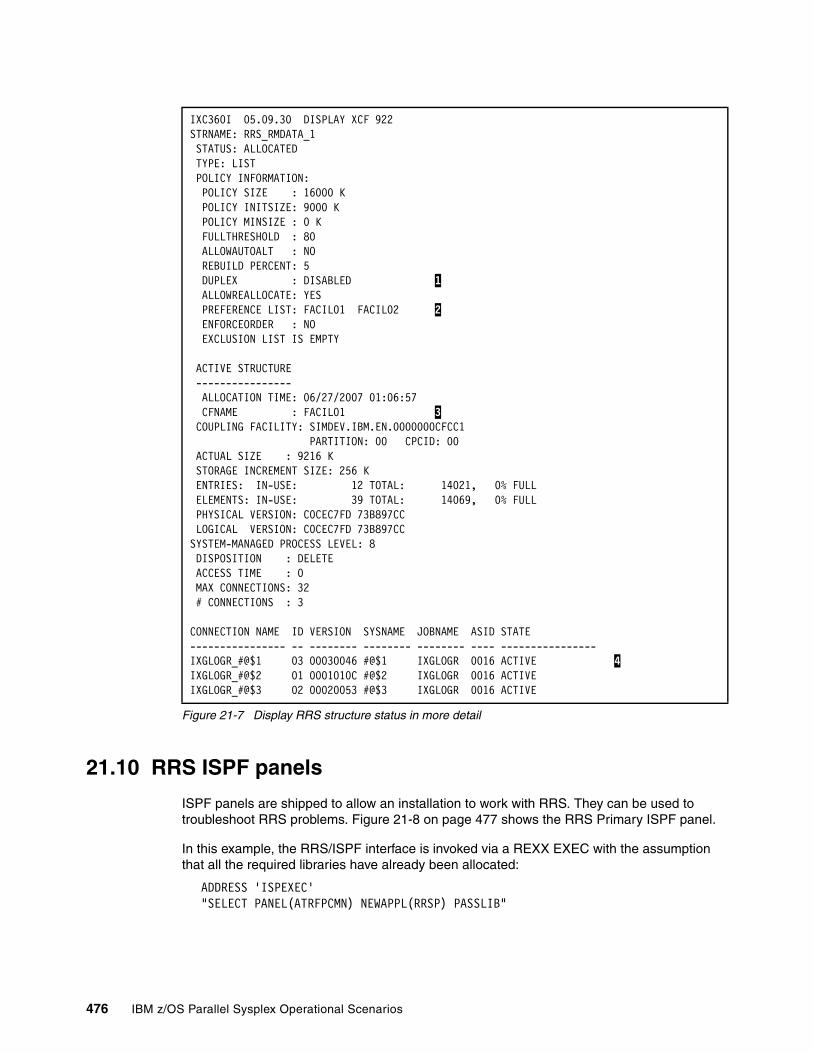
Figure 21-7 Display RRS structure status in more detail
21.10 RRS ISPF panels
ISPF panels are shipped to allow an installation to work with RRS. They can be used to troubleshoot RRS problems. Figure 21-8 on page 477 shows the RRS Primary ISPF panel.
In this example, the RRS/ISPF interface is invoked via a REXX EXEC with the assumption that all the required libraries have already been allocated:
ADDRESS 'ISPEXEC'"SELECT PANEL(ATRFPCMN) NEWAPPL(RRSP) PASSLIB"
IXC360I 05.09.30 DISPLAY XCF 922 STRNAME: RRS_RMDATA_1 STATUS: ALLOCATED TYPE: LIST POLICY INFORMATION: POLICY SIZE : 16000 K POLICY INITSIZE: 9000 K POLICY MINSIZE : 0 K FULLTHRESHOLD : 80 ALLOWAUTOALT : NO REBUILD PERCENT: 5 DUPLEX : DISABLED 1 ALLOWREALLOCATE: YES PREFERENCE LIST: FACIL01 FACIL02 2 ENFORCEORDER : NO EXCLUSION LIST IS EMPTY ACTIVE STRUCTURE ---------------- ALLOCATION TIME: 06/27/2007 01:06:57 CFNAME : FACIL01 3 COUPLING FACILITY: SIMDEV.IBM.EN.0000000CFCC1 PARTITION: 00 CPCID: 00 ACTUAL SIZE : 9216 K STORAGE INCREMENT SIZE: 256 K ENTRIES: IN-USE: 12 TOTAL: 14021, 0% FULL ELEMENTS: IN-USE: 39 TOTAL: 14069, 0% FULL PHYSICAL VERSION: C0CEC7FD 73B897CC LOGICAL VERSION: C0CEC7FD 73B897CC SYSTEM-MANAGED PROCESS LEVEL: 8 DISPOSITION : DELETE ACCESS TIME : 0 MAX CONNECTIONS: 32 # CONNECTIONS : 3 CONNECTION NAME ID VERSION SYSNAME JOBNAME ASID STATE ---------------- -- -------- -------- -------- ---- ---------------- IXGLOGR_#@$1 03 00030046 #@$1 IXGLOGR 0016 ACTIVE 4 IXGLOGR_#@$2 01 0001010C #@$2 IXGLOGR 0016 ACTIVE IXGLOGR_#@$3 02 00020053 #@$3 IXGLOGR 0016 ACTIVE
476 IBM z/OS Parallel Sysplex Operational Scenarios
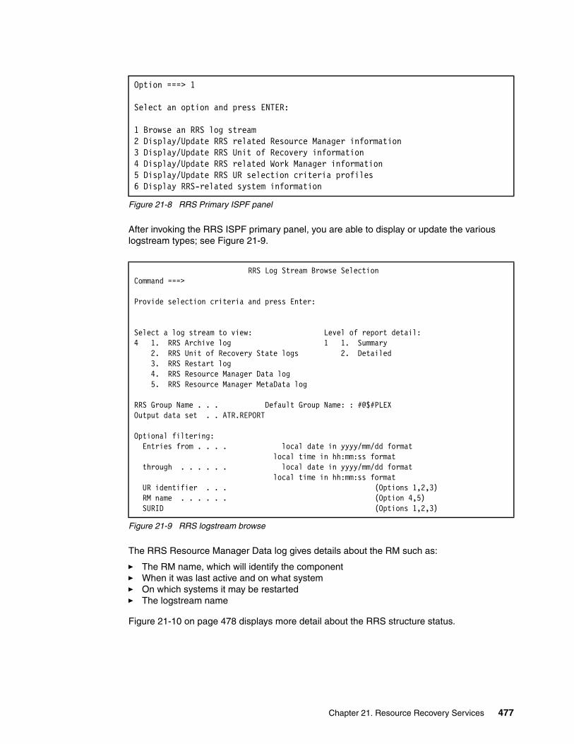
Figure 21-8 RRS Primary ISPF panel
After invoking the RRS ISPF primary panel, you are able to display or update the various logstream types; see Figure 21-9.
Figure 21-9 RRS logstream browse
The RRS Resource Manager Data log gives details about the RM such as:
� The RM name, which will identify the component� When it was last active and on what system� On which systems it may be restarted� The logstream name
Figure 21-10 on page 478 displays more detail about the RRS structure status.
Option ===> 1 Select an option and press ENTER: 1 Browse an RRS log stream 2 Display/Update RRS related Resource Manager information 3 Display/Update RRS Unit of Recovery information 4 Display/Update RRS related Work Manager information 5 Display/Update RRS UR selection criteria profiles 6 Display RRS-related system information
RRS Log Stream Browse Selection Command ===> Provide selection criteria and press Enter: Select a log stream to view: Level of report detail: 4 1. RRS Archive log 1 1. Summary 2. RRS Unit of Recovery State logs 2. Detailed 3. RRS Restart log 4. RRS Resource Manager Data log 5. RRS Resource Manager MetaData log RRS Group Name . . . Default Group Name: : #@$#PLEX Output data set . . ATR.REPORT Optional filtering: Entries from . . . . local date in yyyy/mm/dd format local time in hh:mm:ss format through . . . . . . local date in yyyy/mm/dd format local time in hh:mm:ss format UR identifier . . . (Options 1,2,3) RM name . . . . . . (Option 4,5) SURID (Options 1,2,3)
Chapter 21. Resource Recovery Services 477

Figure 21-10 Output from RRS resource manager data log
21.11 Staging data sets, duplexing, and volatility
Staging data sets are required for DASD only log streams. They are optional for CF structure-based logstreams and staging data sets.
Whether or not the logstreams are duplexed with staging data sets on disk or in a IXGLOGR data space will depend on the following:
� When STG_DUPLEX(YES) with DUPLEXMODE(UNCOND) is specified in the LOGSTREAM definition in the LOGR policy, LOGGER will write each transaction to a staging data set on DASD every time a transaction is written to the CF.
� If DUPLEXMODE is CONDITIONAL, LOGGER will check for either condition of VOLATILITY or FAILURE DEPENDENCE. If either is true, then LOGGER will DUPLEX to a staging data set as described previously.
� If STG_DUPLEX(NO) is specified on the LOGSTREAM definition then LOGGER will write each transaction to interim storage located in the IXGLOGR data space every time a transaction is written to the CF.
Your CF is VOLATILE (as opposed to NON-VOLATILE) if it does not have a backup battery or alternate power source.
Your system is FAILURE DEPENDENT if it shares a power source with the CF. Essentially, a power failure that affects one system or CF would affect the other. The system is FAILURE INDEPENDENT when there is no shared power source between the two.
You could potentially be exposed to data loss if:
� The system is FAILURE DEPENDENT, the CF is VOLATILE, and the LOGSTREAMs are not DUPLEXed using staging data sets.
Menu Utilities Compilers Help ssssssssssssssssssssssssssssssssssssssssssssssssssssssssssssssssssssssssssssss BROWSE MACNIV.ATR.REPORT Line 00000000 Col 001 080 Command ===> Scroll ===> PAGE********************************* Top of Data *********************************RRS/MVS LOG STREAM BROWSE SUMMARY REPORT READING ATR.#@$#PLEX.RM.DATA LOG STREAM #@$2 2007/06/27 02:58:49.450178 BLOCKID=00000000000155B9 RESOURCE MANAGER=CSQ.RRSATF.IBM.PSM2 LOGGING SYSTEM=#@$2 RESOURCE MANAGER MAY RESTART ON ANY SYSTEM RESOURCE MANAGER WAS LAST ACTIVE WITH RRS ON SYSTEM #@$2 LOG NAME IS CSQ3.MQ.RRS.IBM.PSM2 RESTART ANYTIME SUPPORTED LOG INSTANCE NUMBER: 2007/06/27 06:58:04.069718 #@$2 2007/06/27 02:58:49.451368 BLOCKID=0000000000015691 RESOURCE MANAGER=CSQ.RRSATF.IBM.PSM1 LOGGING SYSTEM=#@$2 RESOURCE MANAGER MAY RESTART ON ANY SYSTEM RESOURCE MANAGER WAS LAST ACTIVE WITH RRS ON SYSTEM #@$1 LOG NAME IS CSQ3.MQ.RRS.IBM.PSM1 RESTART ANYTIME SUPPORTED LOG INSTANCE NUMBER: 2007/06/27 06:58:03.066048
478 IBM z/OS Parallel Sysplex Operational Scenarios
� If the system is FAILURE DEPENDENT and the CF is NON-VOLATILE or the system is FAILURE INDEPENDENT and the CF is VOLATILE, you could be exposed to data loss if you lose or shut down both the system and CF while not DUPLEXing using staging data sets. The other factor in this scenario that causes the data loss is if any exploiters of LOGGER still have connections to their LOGSTREAMs.
� If the system is FAILURE INDEPENDENT and the CF is NON-VOLATILE, then you do not need to DUPLEX to limit exposure to the data loss condition.
When RRS suffers a loss of data:
� If a loss of data was detected against the RM.DATA logstream a cold start is required for RRS to successfully initialize. It is strongly recommended that you use unconditional duplexing for the RM.DATA log because any loss of data, unresolved gap, or permanent error will force an RRS cold start.
� If a loss of data was detected against the RESTART logstream, RRS has already successfully initialized but any resource manager attempting to RESTART with RRS will fail with messages ATR212I ATR209I. To allow these resource managers to restart with RRS, an RRS cold start is necessary.
� System Logger normally keeps a second copy of the data written to the CF in a data space. This provides two copies of the data, so that one copy will always be available in the event of the failure of either z/OS or the CF. This is satisfactory as long as the CF is failure-independent (in a separate CPC and non-volatile) from z/OS. If the CF is in the same CPC as a connected z/OS image, or uses volatile storage, the System Logger uses DASD data sets, known as staging data sets, to maintain copies of the log stream data that would otherwise be vulnerable to a failure that impacts both the CF and the z/OS system.
Although the use of staging data sets is useful from the point of view of guaranteeing the availability of the data, there is a performance overhead when using them. The response time from a CF is generally in the order of 100 times faster than the response time from DASD. If Logger is using staging data sets, which must be on DASD, the requesting task is not told that the write request is complete until both the write to the CF and the I/O to DASD is finished. This has an adverse effect on every transaction that is causing data to be written to the associated logstream.
One method of determining whether staging data sets are in use for a logstream is by using the command:
D LOGGER,LOGSTREAM,STRNAME=xxxxxxx
Logging functions that use DASD for staging data sets to duplicate data in structures benefit greatly from CF Duplexing. Using CF Duplexing instead of staging data sets makes duplication more practical and thus improves availability. Eliminating Staging Data Sets for the System Logger as a requirement for availability if a CF or Logger structure fails. This is expected to provide both CPU and response time benefit.
21.12 RRS Health Checker definitions
There is a sample Health Checker procedure which is shipped with z/OS and is available in SYS1.SAMPLIB member name ATRHZS00. It contains override policies for RRS checks.
For more information about Health Checker, refer to Chapter 12, “IBM z/OS Health Checker” on page 257.
Chapter 21. Resource Recovery Services 479

21.13 RRS troubleshooting using batch jobs
There are sample procedures available in SYS1.SAMPLIB to assist in diagnosing problems within RRS. Follow the modification instructions in the samples to run it in your own environment.
� ATRBATCH
Produce a readable version of a RRS logstream; Figure 21-11shows an ATRBATCH sample report.
Figure 21-11 ATRBATCH sample report
� ATRBDISP
Produce detailed information about every UR known to RRS.
RRS/MVS LOG STREAM BROWSE DETAIL REPORT READING ATR.#@$#PLEX.MAIN.UR LOG STREAM #@$3 2007/02/25 17:04:21.098521 BLOCKID=0000000000037681 URID=C03647C67E5DBF140000000001020000 LOGSTREAM=ATR.#@$#PLEX.MAIN.UR PARENT URID=00000000000000000000000000000000 SURID=N/A WORK MANAGER NAME=#@$3.Q6G4BRK.00BD STATE=InCommit EXITFLAGS=00840000 FLAGS=20000000 LUWID= TID= GTID= FORMATID= (decimal) (hexadecimal) GTRID= BQUAL= RMNAME=DSN.RRSATF.IBM.D81D ROLE=Participant CMITCODE=00000FFF BACKCODE=00000FFF PROTOCOL=PresumeAbort READING ATR.#@$#PLEX.DELAYED.UR LOG STREAM #@$3 2005/06/30 12:12:05.907016 BLOCKID=0000000000000001 URID=BD3D78047E62CBA00000001601020000 LOGSTREAM=ATR.#@$#PLEX.DELAYED.UR PARENT URID=00000000000000000000000000000000 SURID=N/A WORK MANAGER NAME=#@$3.PMQ2BRK1.015F STATE=InPrepare EXITFLAGS=00040000 FLAGS=20000000 LUWID= TID= GTID= FORMATID= (decimal) (hexadecimal) GTRID= BQUAL= RMNAME=DSN.RRSATF.IBM.D61B ROLE=Participant CMITCODE=00000FFF BACKCODE=00000FFF PROTOCOL=PresumeNothing
480 IBM z/OS Parallel Sysplex Operational Scenarios

21.14 Defining RRS to Automatic Restart Manager
If RRS fails, it can use Automatic Restart Manager (ARM) to restart itself in a different address space on the same system. RRS, however, will not restart itself following a SETRRS CANCEL command. To stop RRS and cause it to restart automatically, use the FORCE command with ARM and ARMRESTART.
To make automatic restart possible, your installation must:
� Provide an ARM couple data set that contains, either explicitly or through defaults, an ARM policy for RRS. When setting up your ARM policy, use the element name SYS_RRS_sysname for RRS.
� Activate the ARM couple data set through a COUPLExx parmlib member or a SETXCF operator command. The data set must be available when RRS starts and when it restarts.
� Ensure that no element-restart denies the restart of an RRS element or changes its restart. An exception is an exit routine that vetoes RRS restart but then itself starts the RRS address space. This technique, however, might delay other elements in the restart group that have to wait for RRS services to become available.
As with other ARM elements, an ENF signal for event 38 occurs when RRS registers with automatic restart management or is automatically restarted. For information about ARM parameters, refer to Chapter 6, “Automatic Restart Manager” on page 83.
Chapter 21. Resource Recovery Services 481

482 IBM z/OS Parallel Sysplex Operational Scenarios

Chapter 22. z/OS UNIX
This chapter discusses the UNIX System Services environment, which is now called z/OS UNIX. It describes a shared zFS/HFS environment and examines some zFS commands.
For more information about these topics, refer to z/OS UNIX System Services Planning, GA22-7800 or z/OS System Services Command Reference, SA22-7802.
For more information about ZFS™, refer to z/OS Distributed File Service zFS Administration, SC24-5989.
22
© Copyright IBM Corp. 2009. All rights reserved. 483
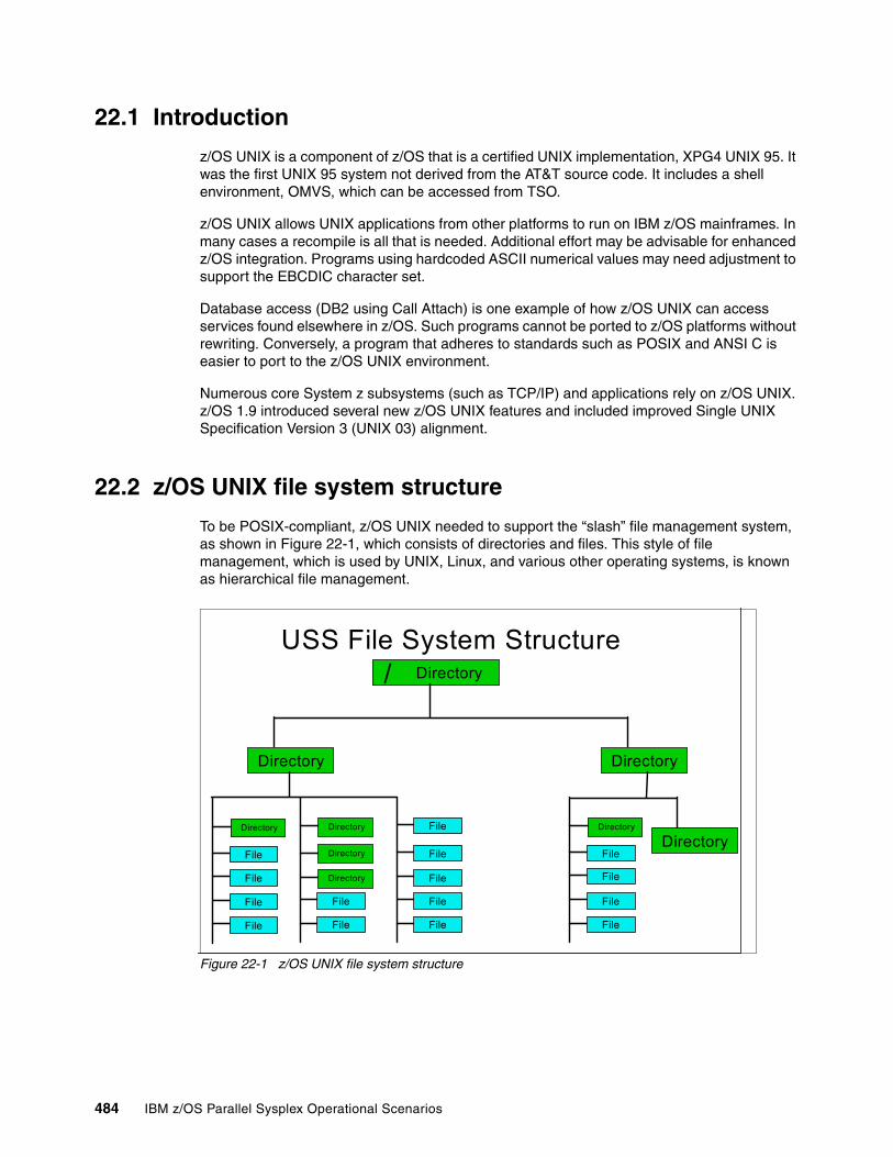
22.1 Introduction
z/OS UNIX is a component of z/OS that is a certified UNIX implementation, XPG4 UNIX 95. It was the first UNIX 95 system not derived from the AT&T source code. It includes a shell environment, OMVS, which can be accessed from TSO.
z/OS UNIX allows UNIX applications from other platforms to run on IBM z/OS mainframes. In many cases a recompile is all that is needed. Additional effort may be advisable for enhanced z/OS integration. Programs using hardcoded ASCII numerical values may need adjustment to support the EBCDIC character set.
Database access (DB2 using Call Attach) is one example of how z/OS UNIX can access services found elsewhere in z/OS. Such programs cannot be ported to z/OS platforms without rewriting. Conversely, a program that adheres to standards such as POSIX and ANSI C is easier to port to the z/OS UNIX environment.
Numerous core System z subsystems (such as TCP/IP) and applications rely on z/OS UNIX. z/OS 1.9 introduced several new z/OS UNIX features and included improved Single UNIX Specification Version 3 (UNIX 03) alignment.
22.2 z/OS UNIX file system structure
To be POSIX-compliant, z/OS UNIX needed to support the “slash” file management system, as shown in Figure 22-1, which consists of directories and files. This style of file management, which is used by UNIX, Linux, and various other operating systems, is known as hierarchical file management.
Figure 22-1 z/OS UNIX file system structure
USS File System Structure/ Directory
Directory Directory
Directory
File
File
File
File
Directory
File
File
File
File
Directory
File
File
Directory
Directory
Directory
File
File
File
File
File
484 IBM z/OS Parallel Sysplex Operational Scenarios
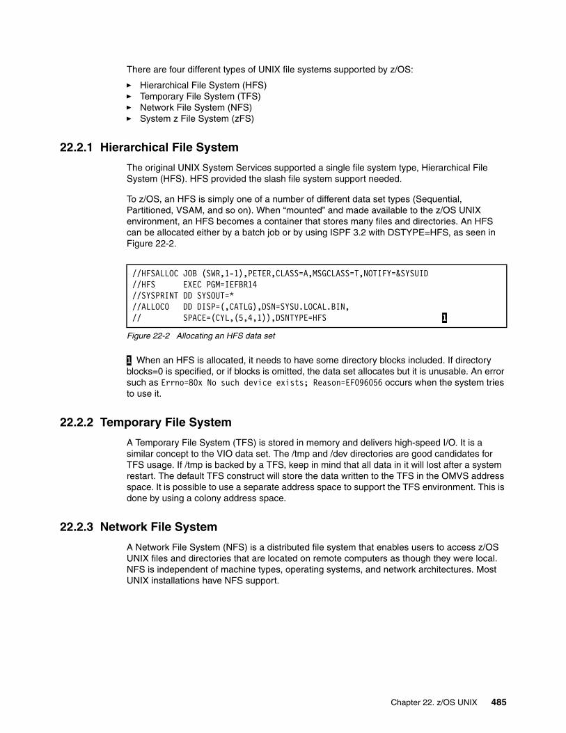
There are four different types of UNIX file systems supported by z/OS:
� Hierarchical File System (HFS)� Temporary File System (TFS)� Network File System (NFS)� System z File System (zFS)
22.2.1 Hierarchical File System
The original UNIX System Services supported a single file system type, Hierarchical File System (HFS). HFS provided the slash file system support needed.
To z/OS, an HFS is simply one of a number of different data set types (Sequential, Partitioned, VSAM, and so on). When “mounted” and made available to the z/OS UNIX environment, an HFS becomes a container that stores many files and directories. An HFS can be allocated either by a batch job or by using ISPF 3.2 with DSTYPE=HFS, as seen in Figure 22-2.
Figure 22-2 Allocating an HFS data set
1 When an HFS is allocated, it needs to have some directory blocks included. If directory blocks=0 is specified, or if blocks is omitted, the data set allocates but it is unusable. An error such as Errno=80x No such device exists; Reason=EF096056 occurs when the system tries to use it.
22.2.2 Temporary File System
A Temporary File System (TFS) is stored in memory and delivers high-speed I/O. It is a similar concept to the VIO data set. The /tmp and /dev directories are good candidates for TFS usage. If /tmp is backed by a TFS, keep in mind that all data in it will lost after a system restart. The default TFS construct will store the data written to the TFS in the OMVS address space. It is possible to use a separate address space to support the TFS environment. This is done by using a colony address space.
22.2.3 Network File System
A Network File System (NFS) is a distributed file system that enables users to access z/OS UNIX files and directories that are located on remote computers as though they were local. NFS is independent of machine types, operating systems, and network architectures. Most UNIX installations have NFS support.
//HFSALLOC JOB (SWR,1-1),PETER,CLASS=A,MSGCLASS=T,NOTIFY=&SYSUID//HFS EXEC PGM=IEFBR14//SYSPRINT DD SYSOUT=*//ALLOC0 DD DISP=(,CATLG),DSN=SYSU.LOCAL.BIN,// SPACE=(CYL,(5,4,1)),DSNTYPE=HFS 1
Chapter 22. z/OS UNIX 485
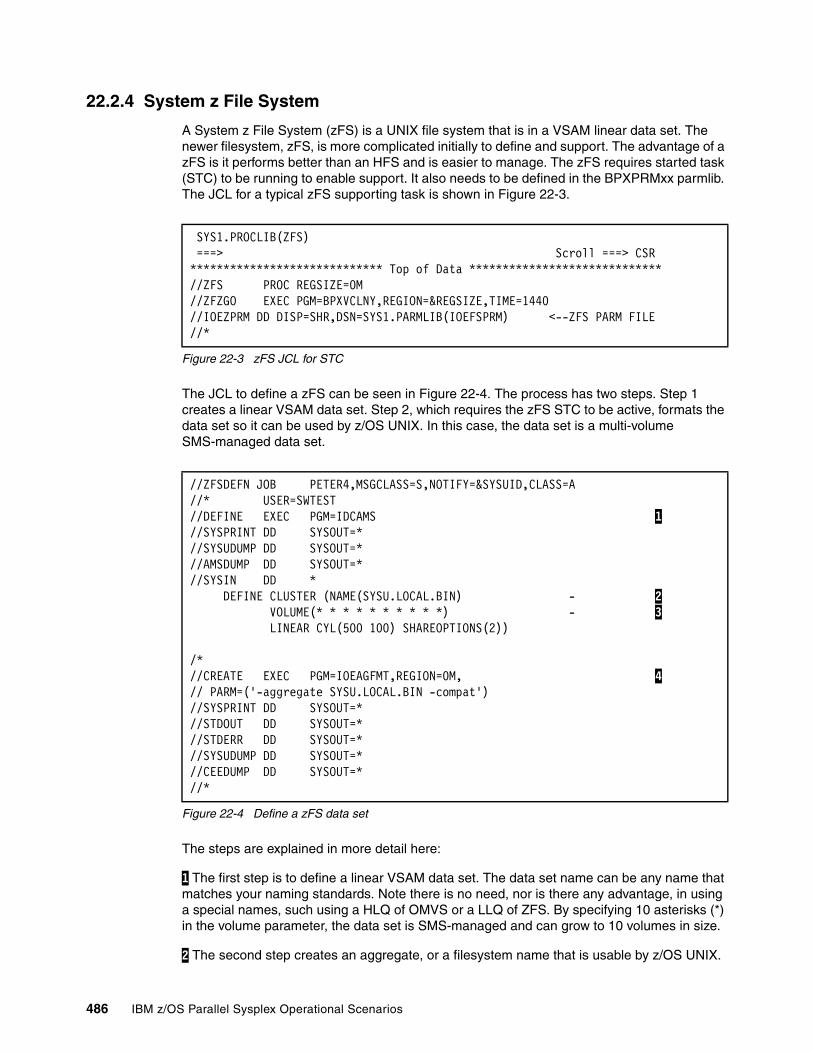
22.2.4 System z File System
A System z File System (zFS) is a UNIX file system that is in a VSAM linear data set. The newer filesystem, zFS, is more complicated initially to define and support. The advantage of a zFS is it performs better than an HFS and is easier to manage. The zFS requires started task (STC) to be running to enable support. It also needs to be defined in the BPXPRMxx parmlib. The JCL for a typical zFS supporting task is shown in Figure 22-3.
Figure 22-3 zFS JCL for STC
The JCL to define a zFS can be seen in Figure 22-4. The process has two steps. Step 1 creates a linear VSAM data set. Step 2, which requires the zFS STC to be active, formats the data set so it can be used by z/OS UNIX. In this case, the data set is a multi-volume SMS-managed data set.
Figure 22-4 Define a zFS data set
The steps are explained in more detail here:
1 The first step is to define a linear VSAM data set. The data set name can be any name that matches your naming standards. Note there is no need, nor is there any advantage, in using a special names, such using a HLQ of OMVS or a LLQ of ZFS. By specifying 10 asterisks (*) in the volume parameter, the data set is SMS-managed and can grow to 10 volumes in size.
2 The second step creates an aggregate, or a filesystem name that is usable by z/OS UNIX.
SYS1.PROCLIB(ZFS) ===> Scroll ===> CSR ***************************** Top of Data *****************************//ZFS PROC REGSIZE=0M //ZFZGO EXEC PGM=BPXVCLNY,REGION=®SIZE,TIME=1440 //IOEZPRM DD DISP=SHR,DSN=SYS1.PARMLIB(IOEFSPRM) <--ZFS PARM FILE //*
//ZFSDEFN JOB PETER4,MSGCLASS=S,NOTIFY=&SYSUID,CLASS=A //* USER=SWTEST //DEFINE EXEC PGM=IDCAMS 1 //SYSPRINT DD SYSOUT=* //SYSUDUMP DD SYSOUT=* //AMSDUMP DD SYSOUT=* //SYSIN DD * DEFINE CLUSTER (NAME(SYSU.LOCAL.BIN) - 2 VOLUME(* * * * * * * * * *) - 3 LINEAR CYL(500 100) SHAREOPTIONS(2)) /* //CREATE EXEC PGM=IOEAGFMT,REGION=0M, 4 // PARM=('-aggregate SYSU.LOCAL.BIN -compat') //SYSPRINT DD SYSOUT=* //STDOUT DD SYSOUT=* //STDERR DD SYSOUT=* //SYSUDUMP DD SYSOUT=* //CEEDUMP DD SYSOUT=* //*
486 IBM z/OS Parallel Sysplex Operational Scenarios
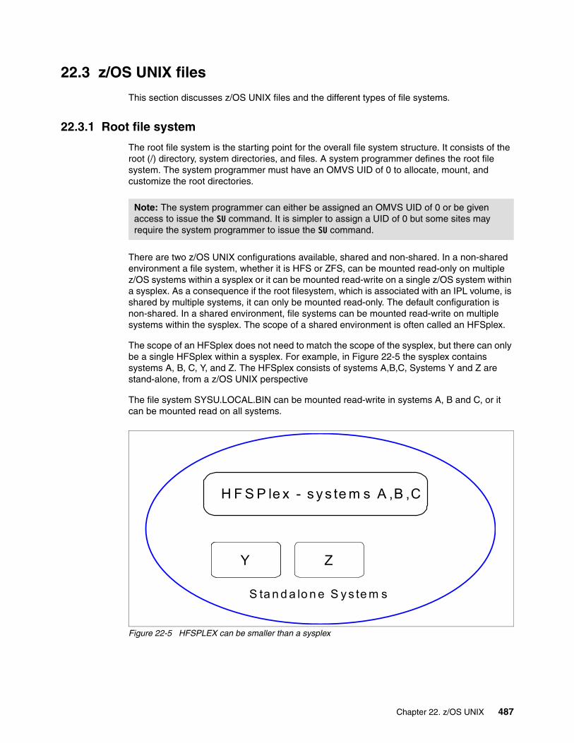
22.3 z/OS UNIX files
This section discusses z/OS UNIX files and the different types of file systems.
22.3.1 Root file system
The root file system is the starting point for the overall file system structure. It consists of the root (/) directory, system directories, and files. A system programmer defines the root file system. The system programmer must have an OMVS UID of 0 to allocate, mount, and customize the root directories.
There are two z/OS UNIX configurations available, shared and non-shared. In a non-shared environment a file system, whether it is HFS or ZFS, can be mounted read-only on multiple z/OS systems within a sysplex or it can be mounted read-write on a single z/OS system within a sysplex. As a consequence if the root filesystem, which is associated with an IPL volume, is shared by multiple systems, it can only be mounted read-only. The default configuration is non-shared. In a shared environment, file systems can be mounted read-write on multiple systems within the sysplex. The scope of a shared environment is often called an HFSplex.
The scope of an HFSplex does not need to match the scope of the sysplex, but there can only be a single HFSplex within a sysplex. For example, in Figure 22-5 the sysplex contains systems A, B, C, Y, and Z. The HFSplex consists of systems A,B,C, Systems Y and Z are stand-alone, from a z/OS UNIX perspective
The file system SYSU.LOCAL.BIN can be mounted read-write in systems A, B and C, or it can be mounted read on all systems.
Figure 22-5 HFSPLEX can be smaller than a sysplex
Note: The system programmer can either be assigned an OMVS UID of 0 or be given access to issue the SU command. It is simpler to assign a UID of 0 but some sites may require the system programmer to issue the SU command.
H F S P le x - s y s te m s A ,B ,C
YYY Z
S ta n d a lo n e S y s te m s
Chapter 22. z/OS UNIX 487

22.3.2 Shared environment
The IBM Redbooks publication ABCs of z/OS System Programming Volume 9, SG24-6989, explains how to set up the shared file system. One way to determine whether you are running a shared file system environment is to use the D OMVS,F command. In Figure 22-6, notice 2 and 3, which are the lines that define an owner or owning system. This indicates this was issued in a file sharing system.
Figure 22-6 D OMVS,F in a file sharing environment
1 The D OMVS,F command displays all the file systems in the HFSplex. 2 A file system that is owned by system #@$3 with AUTOMOVE=U. In this case, when system #@$3 is shut down, the file system is unmounted and becomes unusable. 3 A file system that is owned by system #@$2 with AUTOMOVE=Y. In this case, when system #@$2 is shut down, the file system’s ownership will be taken up by another system in the sysplex and it will still be available.
In a shared file system environment, instead of each system having read-only its own root file system, there is a single HFSplex-wide root file system. If this root file system is damaged or needs to be moved, then the entire HFSplex needs to be restarted. This file system should be very small and consist of directories and links only.
When a file system is mounted, there is a new attribute, called automove, that is assigned. The automove attribute indicates what is to happen to the file system when the system that owns the file system is shut down. There are a number of options available, but the result effectively is that the file system is unmounted and made unavailable or it is moved to another system.
When a file system is mounted read-only, the owning system has no impact because every system directly reads the file system. When the file system is mounted read-write, then the owning system is important. All updates are performed by the “owning” system. When a different system wants to update a file or directory in the file system, the update is communicated to the owning system, using XCF, which then does the actual update.
The I/O on the requesting system is not completed until the owning system indicates it has completed the I/O. As a consequence, it is possible to have significant extra XCF traffic caused by a file system being inappropriately owned. For example, consider a HTTP server running on system MVSA that logs all the HTTP traffic. When the log file is in a file system
D OMVS,F 1 BPXO045I 19.28.59 DISPLAY OMVS 659 OMVS 0010 ACTIVE OMVS=(00,FS) TYPENAME DEVICE ----------STATUS----------- MODE MOUNTED LATCHES ZFS 97 ACTIVE RDWR 07/16/2007 L=33 NAME=OMVS.#@$3.SYSTEM.ZFS 21.30.01 Q=0 PATH=/#@$3 AGGREGATE NAME=OMVS.#@$3.SYSTEM.ZFS 2 OWNER=#@$3 AUTOMOVE=U CLIENT=N ZFS 3 ACTIVE READ 07/16/2007 L=15 NAME=OMVS.ZOSR18.#@$#R3.ROOT 21.30.00 Q=0 PATH=/#@$#R3 AGGREGATE NAME=OMVS.ZOSR18.#@$#R3.ROOT OWNER=#@$2 AUTOMOVE=Y CLIENT=N 3 . . .
488 IBM z/OS Parallel Sysplex Operational Scenarios

owned by MVSB, then all the HTTP logging writes will be transferred, using XCF, from MVSA to MVSB.
As systems are IPLed, the ownership of file systems, especially those that are automove-enabled, can change. This not only can cause significant extra XCF traffic, but can also impact the response time. Your z/OS system programmer is responsible for maintaining the mount configuration, and therefore should know the optimal configuration.
22.4 zFS administration
Figure 22-3 on page 486 shows a sample proc for the zFS support task. This STC is started automatically when the z/OS UNIX environment is started. The STC name is defined in Figure 22-7; in this case it is called ZFS.
Figure 22-7 BPXPRMxx with for ZFS
1 The ZFS supporting task STC name; the JCL needs to be in a system proclib, such as SYS1.PROCLIB.
With z/OS 1.7, the zFS supporting address space was terminated with P ZFS. With z/OS 1.8 and later, it is stopped with the F OMVS,STOPFS=ZFS command; this can be seen in Figure 22-8.
Figure 22-8 Stopping the ZFS address space
1 Command to stop the zFS support address space. 2 Message requesting confirmation that the support address space is to be stopped. 3 Message indicating that a zFS data set is being stopped. 4 Message indicating this system is no longer part of the HFSplex. 5 Message indicating the address space is stopping. 6 If the stoppage was not for an IPL, then the zFS support address space could be restarted. by replying R to this message when the change is complete.
. . .FILESYSTYPE TYPE(ZFS) /* Type of file system to start */ ENTRYPOINT(IOEFSCM) /* Entry Point of load module */ ASNAME(ZFS) /* Procedure name */ 1 . . .
F OMVS,STOPPFS=ZFS 1 014 BPXI078D STOP OF ZFS REQUESTED. REPLY 'Y' TO 2 PROCEED. ANY OTHER REPLY WILL CANCEL THIS STOP. 14y IEE600I REPLY TO 014 IS;Y IOEZ00050I zFS kernel: Stop command received. IOEZ00048I Detaching aggregate OMVS.ZOSR18.#@$#R3.ROOT 3 IOEZ00387E System #@$3 has left group IOEZFS, aggregate recovery in progress. IOEZ00387E System #@$3 has left group IOEZFS, aggregate recovery in progress. IOEZ00357I Successfully left the sysplex group. 4 IOEZ00057I zFS kernel program IOEFSCM is ending 5 IEF352I ADDRESS SPACE UNAVAILABLE $HASP395 ZFS ENDED 015 BPXF032D FILESYSTYPE ZFS TERMINATED. REPLY 6 'R' WHEN READY TO RESTART. REPLY 'I' TO IGNORE.
Chapter 22. z/OS UNIX 489
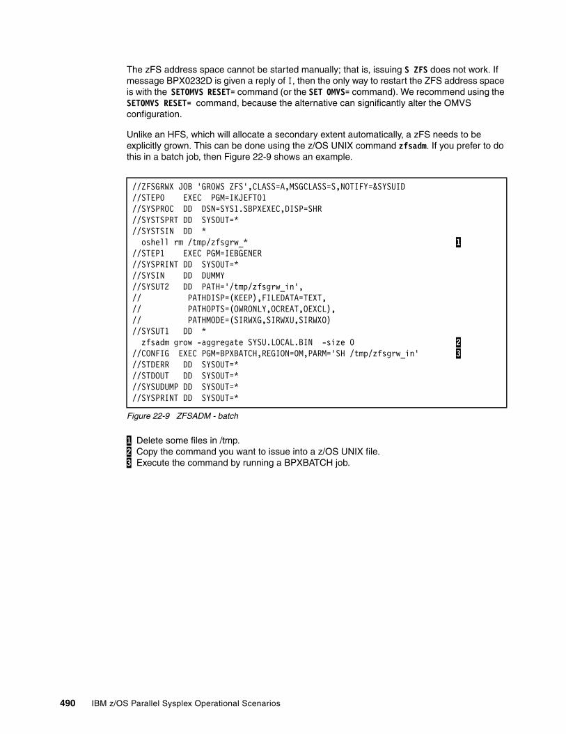
The zFS address space cannot be started manually; that is, issuing S ZFS does not work. If message BPX0232D is given a reply of I, then the only way to restart the ZFS address space is with the SETOMVS RESET= command (or the SET OMVS= command). We recommend using the SETOMVS RESET= command, because the alternative can significantly alter the OMVS configuration.
Unlike an HFS, which will allocate a secondary extent automatically, a zFS needs to be explicitly grown. This can be done using the z/OS UNIX command zfsadm. If you prefer to do this in a batch job, then Figure 22-9 shows an example.
Figure 22-9 ZFSADM - batch
1 Delete some files in /tmp. 2 Copy the command you want to issue into a z/OS UNIX file. 3 Execute the command by running a BPXBATCH job.
//ZFSGRWX JOB 'GROWS ZFS',CLASS=A,MSGCLASS=S,NOTIFY=&SYSUID //STEP0 EXEC PGM=IKJEFT01 //SYSPROC DD DSN=SYS1.SBPXEXEC,DISP=SHR //SYSTSPRT DD SYSOUT=* //SYSTSIN DD * oshell rm /tmp/zfsgrw_* 1 //STEP1 EXEC PGM=IEBGENER //SYSPRINT DD SYSOUT=* //SYSIN DD DUMMY //SYSUT2 DD PATH='/tmp/zfsgrw_in', // PATHDISP=(KEEP),FILEDATA=TEXT, // PATHOPTS=(OWRONLY,OCREAT,OEXCL), // PATHMODE=(SIRWXG,SIRWXU,SIRWXO) //SYSUT1 DD * zfsadm grow -aggregate SYSU.LOCAL.BIN -size 0 2 //CONFIG EXEC PGM=BPXBATCH,REGION=0M,PARM='SH /tmp/zfsgrw_in' 3 //STDERR DD SYSOUT=* //STDOUT DD SYSOUT=* //SYSUDUMP DD SYSOUT=* //SYSPRINT DD SYSOUT=*
490 IBM z/OS Parallel Sysplex Operational Scenarios
Appendix A. Operator commands
This appendix lists and describes operator commands that can help you to manage your Parallel Sysplex environment.
A
© Copyright IBM Corp. 2009. All rights reserved. 491
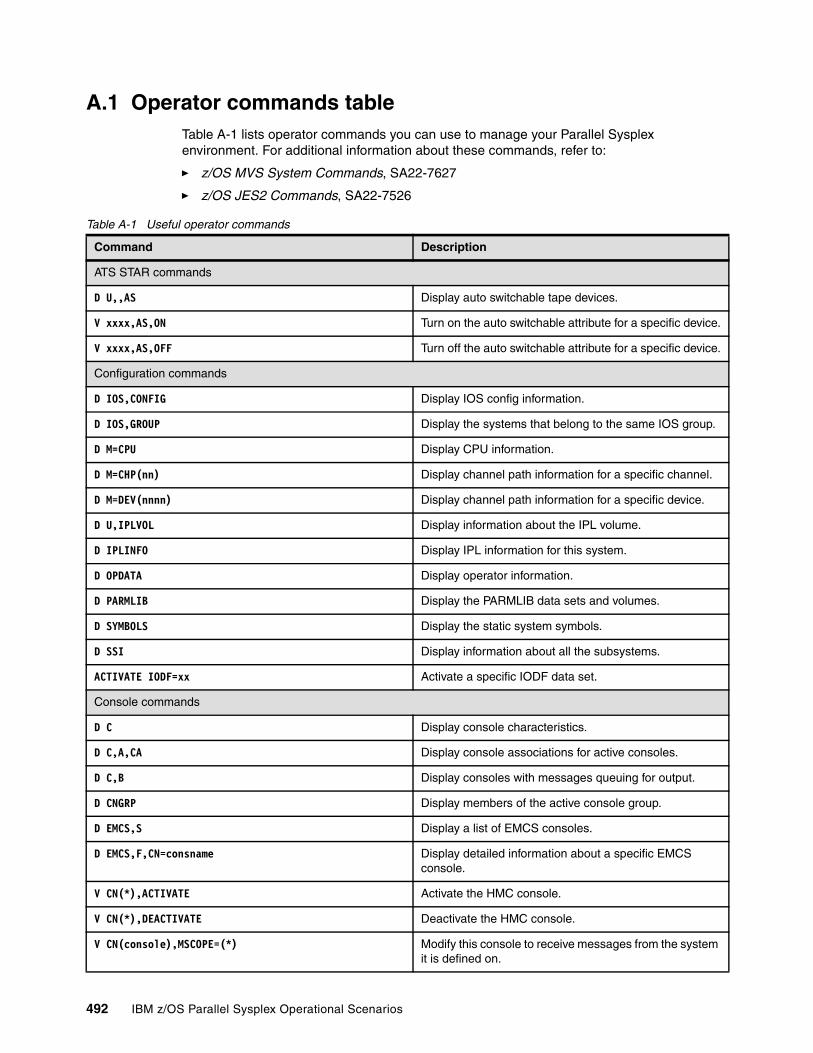
A.1 Operator commands tableTable A-1 lists operator commands you can use to manage your Parallel Sysplex environment. For additional information about these commands, refer to:
� z/OS MVS System Commands, SA22-7627
� z/OS JES2 Commands, SA22-7526
Table A-1 Useful operator commands
Command Description
ATS STAR commands
D U,,AS Display auto switchable tape devices.
V xxxx,AS,ON Turn on the auto switchable attribute for a specific device.
V xxxx,AS,OFF Turn off the auto switchable attribute for a specific device.
Configuration commands
D IOS,CONFIG Display IOS config information.
D IOS,GROUP Display the systems that belong to the same IOS group.
D M=CPU Display CPU information.
D M=CHP(nn) Display channel path information for a specific channel.
D M=DEV(nnnn) Display channel path information for a specific device.
D U,IPLVOL Display information about the IPL volume.
D IPLINFO Display IPL information for this system.
D OPDATA Display operator information.
D PARMLIB Display the PARMLIB data sets and volumes.
D SYMBOLS Display the static system symbols.
D SSI Display information about all the subsystems.
ACTIVATE IODF=xx Activate a specific IODF data set.
Console commands
D C Display console characteristics.
D C,A,CA Display console associations for active consoles.
D C,B Display consoles with messages queuing for output.
D CNGRP Display members of the active console group.
D EMCS,S Display a list of EMCS consoles.
D EMCS,F,CN=consname Display detailed information about a specific EMCS console.
V CN(*),ACTIVATE Activate the HMC console.
V CN(*),DEACTIVATE Deactivate the HMC console.
V CN(console),MSCOPE=(*) Modify this console to receive messages from the system it is defined on.
492 IBM z/OS Parallel Sysplex Operational Scenarios

V CN(console),MSCOPE=(*ALL) Modify this console to receive messages from all systems in the sysplex.
V CN(console),MSCOPE=(sys1,sys2,...) Modify this console to receive messages from specific systems in the sysplex.
V CN(console),ROUT=(ALL) Modify this console to receive messages with all routing codes.
V CN(console),ROUT=(rcode1,rcode2,...) Modify this console to receive messages with specific routing codes.
RO sysname,command Route command to a specific system.
RO *ALL,command Route command to all systems.
RO *OTHER,commands Route command to all systems except the system where this command was entered.
DEVSERV commands
DS P,nnnn Display the status of a specific device.
DS QP,nnnn Display the PAV configuration of a specific device.
DS SMS,nnnn Display the SMS information of a specific device.
DQ QD,nnnn Display diagnostic information about the status of a specific device and its control unit.
ETR commands
D ETR Display the status of STP or the Sysplex Timer.
SETETR,PORT=n Enable ETR port 0 or 1.
GRS commands
D GRS,A Display GRS configuration information.
D GRS,ANALYZE Display an analysis of system contention.
D GRS,C Display GRS contention information.
D GRS,RES=(*,dsname) Display enqueue contention for a single data set.
D GRS,DEV=nnnn Display RESERVE requests for a specific device.
D GRS,DELAY Display jobs which are delaying a T GRSRNL command.
D GRS,SUSPEND Display jobs which are suspended, pending the completion of a T GRSRNL command.
T GRSRNL=(xx) Implement a new GRS RNL member dynamically.
JES2 commands
$D MEMBER(*) Display every member of the JES2 MAS.
$E MEMBER(sysname) Perform cleanup processing after a member of a MAS fails.
$D JOBQ,SPOOL=(%>n) Display jobs using more than a specified percentage of the spool.
Command Description
Appendix A. Operator commands 493
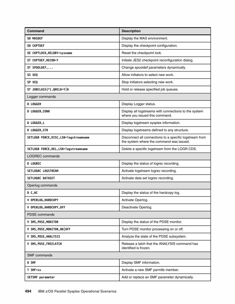
$D MASDEF Display the MAS environment.
$D CKPTDEF Display the checkpoint configuration.
$E CKPTLOCK,HELDBY=sysname Reset the checkpoint lock.
$T CKPTDEF,RECON=Y Initiate JES2 checkpoint reconfiguration dialog.
$T SPOOLDEF,... Change spooldef parameters dynamically.
$S XEQ Allow initiators to select new work.
$P XEQ Stop initiators selecting new work.
$T JOBCLASS(*),QHELD=Y|N Hold or release specified job queues.
Logger commands
D LOGGER Display Logger status.
D LOGGER,CONN Display all logstreams with connections to the system where you issued this command.
D LOGGER,L Display logstream sysplex information.
D LOGGER,STR Display logstreams defined to any structure.
SETLOGR FORCE,DISC,LSN=logstreamname Disconnect all connections to a specific logstream from the system where the command was issued.
SETLOGR FORCE,DEL,LSN=logstreamname Delete a specific logstream from the LOGR CDS.
LOGREC commands
D LOGREC Display the status of logrec recording.
SETLOGRC LOGSTREAM Activate logstream logrec recording.
SETLOGRC DATASET Activate data set logrec recording.
Operlog commands
D C,HC Display the status of the hardcopy log.
V OPERLOG,HARDCOPY Activate Operlog.
V OPERLOG,HARDCOPY,OFF Deactivate Operlog.
PDSE commands
V SMS,PDSE,MONITOR Display the status of the PDSE monitor.
V SMS,PDSE,MONITOR,ON|OFF Turn PDSE monitor processing on or off.
V SMS,PDSE,ANALYSIS Analyze the state of the PDSE subsystem.
V SMS,PDSE,FREELATCH Release a latch that the ANALYSIS command has identified is frozen.
SMF commands
D SMF Display SMF information.
T SMF=xx Activate a new SMF parmlib member.
SETSMF parameter Add or replace an SMF parameter dynamically.
Command Description
494 IBM z/OS Parallel Sysplex Operational Scenarios
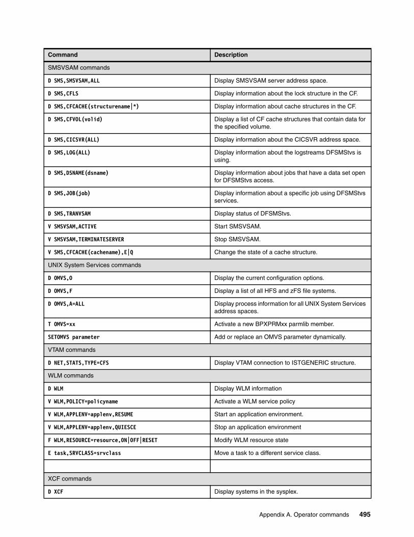
SMSVSAM commands
D SMS,SMSVSAM,ALL Display SMSVSAM server address space.
D SMS,CFLS Display information about the lock structure in the CF.
D SMS,CFCACHE(structurename|*) Display information about cache structures in the CF.
D SMS,CFVOL(volid) Display a list of CF cache structures that contain data for the specified volume.
D SMS,CICSVR(ALL) Display information about the CICSVR address space.
D SMS,LOG(ALL) Display information about the logstreams DFSMStvs is using.
D SMS,DSNAME(dsname) Display information about jobs that have a data set open for DFSMStvs access.
D SMS,JOB(job) Display information about a specific job using DFSMStvs services.
D SMS,TRANVSAM Display status of DFSMStvs.
V SMSVSAM,ACTIVE Start SMSVSAM.
V SMSVSAM,TERMINATESERVER Stop SMSVSAM.
V SMS,CFCACHE(cachename),E|Q Change the state of a cache structure.
UNIX System Services commands
D OMVS,O Display the current configuration options.
D OMVS,F Display a list of all HFS and zFS file systems.
D OMVS,A=ALL Display process information for all UNIX System Services address spaces.
T OMVS=xx Activate a new BPXPRMxx parmlib member.
SETOMVS parameter Add or replace an OMVS parameter dynamically.
VTAM commands
D NET,STATS,TYPE=CFS Display VTAM connection to ISTGENERIC structure.
WLM commands
D WLM Display WLM information
V WLM,POLICY=policyname Activate a WLM service policy
V WLM,APPLENV=applenv,RESUME Start an application environment.
V WLM,APPLENV=applenv,QUIESCE Stop an application environment
F WLM,RESOURCE=resource,ON|OFF|RESET Modify WLM resource state
E task,SRVCLASS=srvclass Move a task to a different service class.
XCF commands
D XCF Display systems in the sysplex.
Command Description
Appendix A. Operator commands 495

D XCF,S,ALL Display systems in the sysplex and their status time stamp.
D XCF,COUPLE Display couple data set information.
D XCF,PI Display pathin devices and structures.
D XCF,PI,DEV=ALL Display status of pathin devices and structures.
D XCF,PO Display pathout devices and structures.
D XCF,PO,DEV=ALL Display status of pathout devices and structures.
D XCF,POL Display information about active policies.
D XCF,POL,TYPE=type Display information about a specific policy.
D XCF,STR Display a list of all the structures defined in the CFRM policy.
D XCF,STR,STAT=ALLOC Display the allocated structures.
D XCF,STR,STRNAME=strname Display detailed information for a specific structure.
D CF Display detailed information about the CFs.
D XCF,CF Display information about the CFs.
D XCF,ARMSTATUS Display information about ARM.
D XCF,ARMSTATUS,DETAIL Display detailed information about ARM.
V XCF,sysname,OFFLINE Vary a system out of the sysplex.
SETXCF COUPLE,ACOUPLE=dsn,TYPE=type Add an alternate couple data set for a specific component.
SETXCF COUPLE,PSWITCH,TYPE=type Remove the primary couple data set and replace it with the alternate couple data set.
SETXCF START,POL,TYPE=type,POLNAME=polname Start a policy.
SETXCF START,REALLOC Reallocates CF structures according to the preflist in the active CFRM policy.
SETXCF START,RB,POPCF=cfname Reallocates CF structures into a specific CF according to the preflist in the active CFRM policy.
SETXCF START,RB,CFNM=cfname,LOC=OTHER Reallocates CF structures into another CF according to their preflist.
SETXCF START,RB,STRNAME=strname Rebuild a CF structure.
SETXCF START,RB,DUPLEX,STRNAME=strname Start duplexing for a CF structure.
SETXCF START,RB,DUPLEX,CFNAME=cfname Start duplexing for all the CF structures in a specific CF.
SETXCF START,ALTER,STRNAME=strname,SIZE=nnnn Start CF structure alter processing to change the structure size.
SETXCF FORCE,STR,STRNAME=strname Delete a persistent CF structure.
SETXCF FORCE,CON,STRNAME=strname,CONNAME=conname Delete a failed-persistent connection.
SETXCF FORCE,STRDUMP,STRNAM=strname Delete a structure dump for a specific structure.
Command Description
496 IBM z/OS Parallel Sysplex Operational Scenarios

SETXCF START,CLASSDEF,CLASS=class Start a transport class.
SETXCF START,MAINTMODE,CFNM=cfname Place a CF into maintenance mode.
SETXCF START,PI,DEV=nnnn Start an inbound signalling path via a CTC.
SETXCF START,PI,STRNM=(strname) Start an inbound signalling path via a CF structure.
SETXCF START,PO,DEV=nnnn Start an outbound signalling path via a CTC.
SETXCF START,PO,STRNM=(strname) Start an outbound signalling path via a CF structure.
SETXCF START,CLASSDEF,CLASS=class Start a transport class.
SETXCF STOP,MAINTMODE,CFNM=cfname Make a CF available for allocations again after maintenance is complete.
SETXCF STOP,PI,DEV=nnnn Stop an inbound signalling path via a CTC.
SETXCF STOP,PI,STRNM=(strname) Stop an inbound signalling path via a CF structure.
SETXCF STOP,PO,DEV=nnnn Stop an outbound signalling path via a CTC.
SETXCF STOP,PO,STRNM=(strname) Stop an outbound signalling path via a CF structure.
SETXCF MODIFY,... Modify XCF parameters:� pathin� pathout� transport classes
Command Description
Appendix A. Operator commands 497

498 IBM z/OS Parallel Sysplex Operational Scenarios
Appendix B. List of structures
Table B-1 on page 500 in this appendix lists information about the exploiters of the Coupling Facility including structure name, structure type, structure disposition, connection disposition, and whether the structure supports rebuild.
B
© Copyright IBM Corp. 2009. All rights reserved. 499
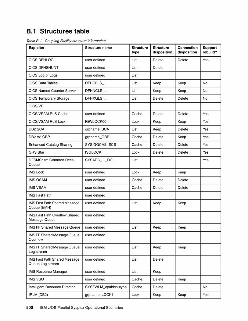
B.1 Structures tableTable B-1 Coupling Facility structure information
Exploiter Structure name Structure type
Structure disposition
Connection disposition
Support rebuild?
CICS DFHLOG user defined List Delete Delete Yes
CICS DFHSHUNT user defined List Delete
CICS Log of Logs user defined List
CICS Data Tables DFHCFLS_... List Keep Keep No
CICS Named Counter Server DFHNCLS_... List Keep Keep No
CICS Temporary Storage DFHXQLS_... List Delete Delete No
CICS/VR
CICS/VSAM RLS Cache user defined Cache Delete Delete Yes
CICS/VSAM RLS Lock IGWLOCK00 Lock Keep Keep Yes
DB2 SCA grpname_SCA List Keep Delete Yes
DB2 V8 GBP grpname_GBP... Cache Delete Keep Yes
Enhanced Catalog Sharing SYSIGGCAS_ECS Cache Delete Delete Yes
GRS Star ISGLOCK Lock Delete Delete Yes
DFSMShsm Common Recall Queue
SYSARC_..._RCL List Yes
IMS Lock user defined Lock Keep Keep
IMS OSAM user defined Cache Delete Delete
IMS VSAM user defined Cache Delete Delete
IMS Fast Path user defined
IMS Fast Path Shared Message Queue (EMH)
user defined List Keep Keep
IMS Fast Path Overflow Shared Message Queue
user defined
IMS FF Shared Message Queue user defined List Keep Keep
IMS FF Shared Message Queue Overflow
user defined
IMS FF Shared Message Queue Log stream
user defined List Keep Keep
IMS Fast Path Shared Message Queue Log stream
user defined List Delete
IMS Resource Manager user defined List Keep
IMS VSO user defined Cache Delete Keep
Intelligent Resource Director SYSZWLM_cpuidcputype Cache Delete No
IRLM (DB2) grpname_LOCK1 Lock Keep Keep Yes
500 IBM z/OS Parallel Sysplex Operational Scenarios
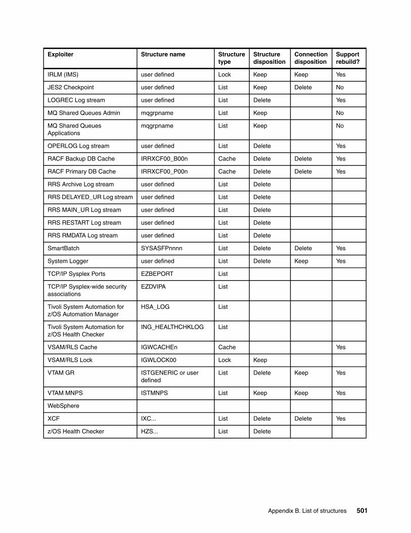
IRLM (IMS) user defined Lock Keep Keep Yes
JES2 Checkpoint user defined List Keep Delete No
LOGREC Log stream user defined List Delete Yes
MQ Shared Queues Admin mqgrpname List Keep No
MQ Shared Queues Applications
mqgrpname List Keep No
OPERLOG Log stream user defined List Delete Yes
RACF Backup DB Cache IRRXCF00_B00n Cache Delete Delete Yes
RACF Primary DB Cache IRRXCF00_P00n Cache Delete Delete Yes
RRS Archive Log stream user defined List Delete
RRS DELAYED_UR Log stream user defined List Delete
RRS MAIN_UR Log stream user defined List Delete
RRS RESTART Log stream user defined List Delete
RRS RMDATA Log stream user defined List Delete
SmartBatch SYSASFPnnnn List Delete Delete Yes
System Logger user defined List Delete Keep Yes
TCP/IP Sysplex Ports EZBEPORT List
TCP/IP Sysplex-wide security associations
EZDVIPA List
Tivoli System Automation for z/OS Automation Manager
HSA_LOG List
Tivoli System Automation for z/OS Health Checker
ING_HEALTHCHKLOG List
VSAM/RLS Cache IGWCACHEn Cache Yes
VSAM/RLS Lock IGWLOCK00 Lock Keep
VTAM GR ISTGENERIC or user defined
List Delete Keep Yes
VTAM MNPS ISTMNPS List Keep Keep Yes
WebSphere
XCF IXC... List Delete Delete Yes
z/OS Health Checker HZS... List Delete
Exploiter Structure name Structure type
Structure disposition
Connection disposition
Support rebuild?
Appendix B. List of structures 501

502 IBM z/OS Parallel Sysplex Operational Scenarios
Appendix C. Stand-alone dump on a Parallel Sysplex example
This appendix provides an example of a stand-alone dump (SAD) that was taken on z/OS system AAIS in the P04AAIBM Parallel Sysplex. The P04AAIBM sysplex environment consists of two z/OS images named AAIS and AAIL running z/OS 1.8.
We IPLed the SADMP program from DASD using device address 4038.
Our SAD output was written to a DASD data set, SYS1.SADMP. It was allocated across two 3390-3 disk volumes, SP413A (413A) and SP413B (413B), using the AMDSADDD REXX exec in SYS1.SBLSCLI0.
We used the HMC as the console for the SADMP program. You can use any console that is defined to the SADMP program.
C
Note: The Parallel Sysplex environment used for the stand-alone dump is from the IBM Australia test bed.
Note: The input and output devices you use for a stand-alone dump in your installation will vary. Consult your system programmer for this information.
© Copyright IBM Corp. 2009. All rights reserved. 503

C.1 Reducing SADUMP capture time
The best stand-alone dump performance is achieved when the dump is taken to a “striped” DASD stand-alone output data set, also called a multi-volume dump group. The stand-alone dump output data set needs to be placed on a volume behind a modern control unit, like the IBM Enterprise Storage subsystem, as opposed to non-ESS DASD or dumping to tape.
C.2 Allocating the SADUMP output data setThe stand-alone output data set is allocated by invoking REXX exec AMDSADDD in SYS1.SBLSCLI0. Refer to z/OS V1R8.0 MVS Diagnosis Tool and Service Aids, GA22-7589, for detailed information about this topic.
When the REXX exec is invoked, various prompts are issued. One of the prompts will be for the output data set; it asks whether it should be allocated multivolume.
When dumping to a DASD dump data set, there are significant performance improvements observed with “striping” the data to a multivolume stand-alone dump data set. Striping refers to the use of spanned volumes for the stand-alone dump output data set. To implement striping, specify a volume list (VOLLIST) in the AMDSADDD REXX exec to designate a list of volumes to use for the data set. In our example, we used volumes SP413A and SP413B.
C.3 Identifying a DASD output device for SADFor this example, we allocated the stand-alone output data set with a name of SYS1.SADMP on volumes SP413A and SP413B on device addresses 413A and 413B.
C.4 Identifying a tape output device for SADIf you are using tapes as the output device for a SAD and the tape device is not part of an Automated Tape Library (ATL), mount a scratch in a tape drive that is online to the z/OS system being dumped. However, if you will be using a tape device that is part of an ATL, then additional steps are required before performing the SAD to the ATL device, as explained here:
1. Take note of the volser for a scratch tape to be used for the SAD and enter it into the ATL.2. Using the console for the ATL, ensure that the tape device being used is configured as a
stand-alone device.3. Enter the tape device address on the ATL console. 4. Enter the volser of the scratch tape to be used through the ATL console.5. The ATL console should issue a message indicating that the mount is complete.
Note: The tasks described in C.1 and C.2 should be carried out by your system programmer, but they are included here for completeness.
Recommendation: Allocate the output data set as multivolume, because this will reduce the amount of time needed to capture the stand-alone dump.
504 IBM z/OS Parallel Sysplex Operational Scenarios
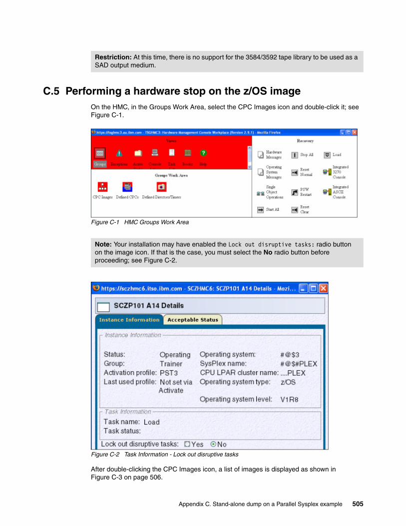
C.5 Performing a hardware stop on the z/OS imageOn the HMC, in the Groups Work Area, select the CPC Images icon and double-click it; see Figure C-1.
Figure C-1 HMC Groups Work Area
Figure C-2 Task Information - Lock out disruptive tasks
After double-clicking the CPC Images icon, a list of images is displayed as shown in Figure C-3 on page 506.
Restriction: At this time, there is no support for the 3584/3592 tape library to be used as a SAD output medium.
Note: Your installation may have enabled the Lock out disruptive tasks: radio button on the image icon. If that is the case, you must select the No radio button before proceeding; see Figure C-2.
Appendix C. Stand-alone dump on a Parallel Sysplex example 505

Figure C-3 AAIS (CPC Images Work Area)
On the HMC, in the CPC Images Work Area, we selected system AAIS by single-clicking it to highlight it. Then we double-clicked the STOP All icon in the CPC Recovery window, as shown in Figure C-4.
Figure C-4 Selecting STOP All on HMC
A confirmation panel was displayed, as shown in Figure C-5 on page 507.
506 IBM z/OS Parallel Sysplex Operational Scenarios
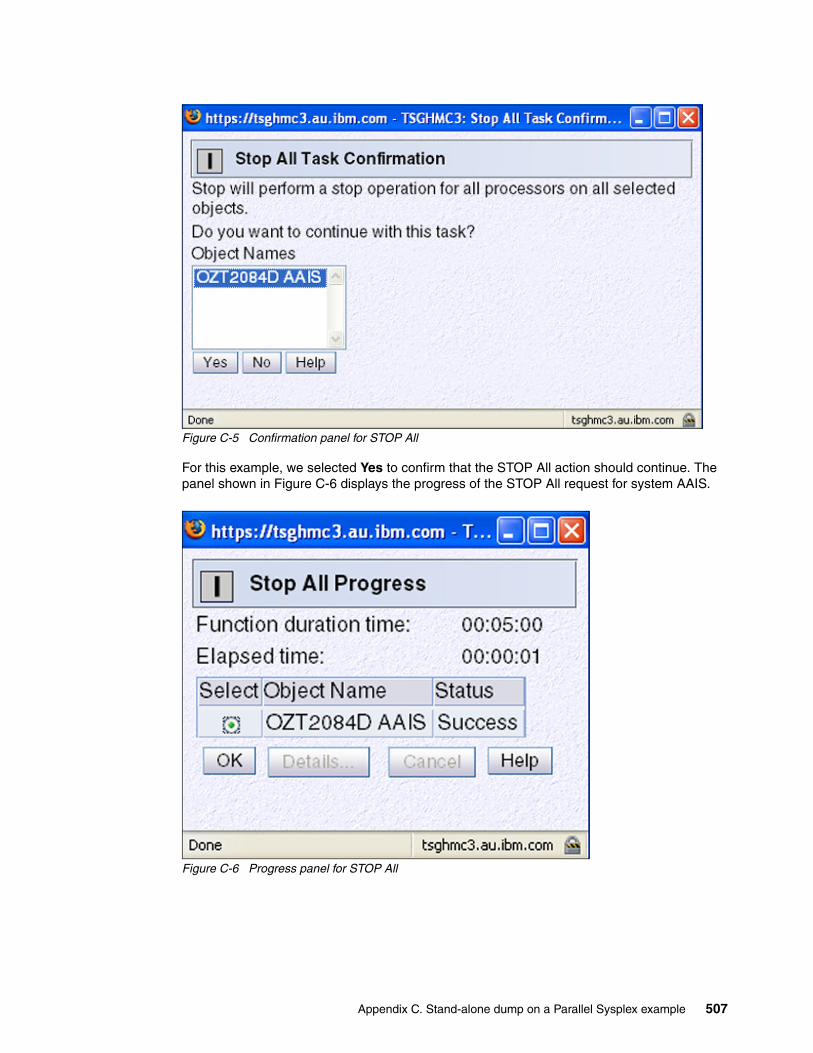
Figure C-5 Confirmation panel for STOP All
For this example, we selected Yes to confirm that the STOP All action should continue. The panel shown in Figure C-6 displays the progress of the STOP All request for system AAIS.
Figure C-6 Progress panel for STOP All
Appendix C. Stand-alone dump on a Parallel Sysplex example 507
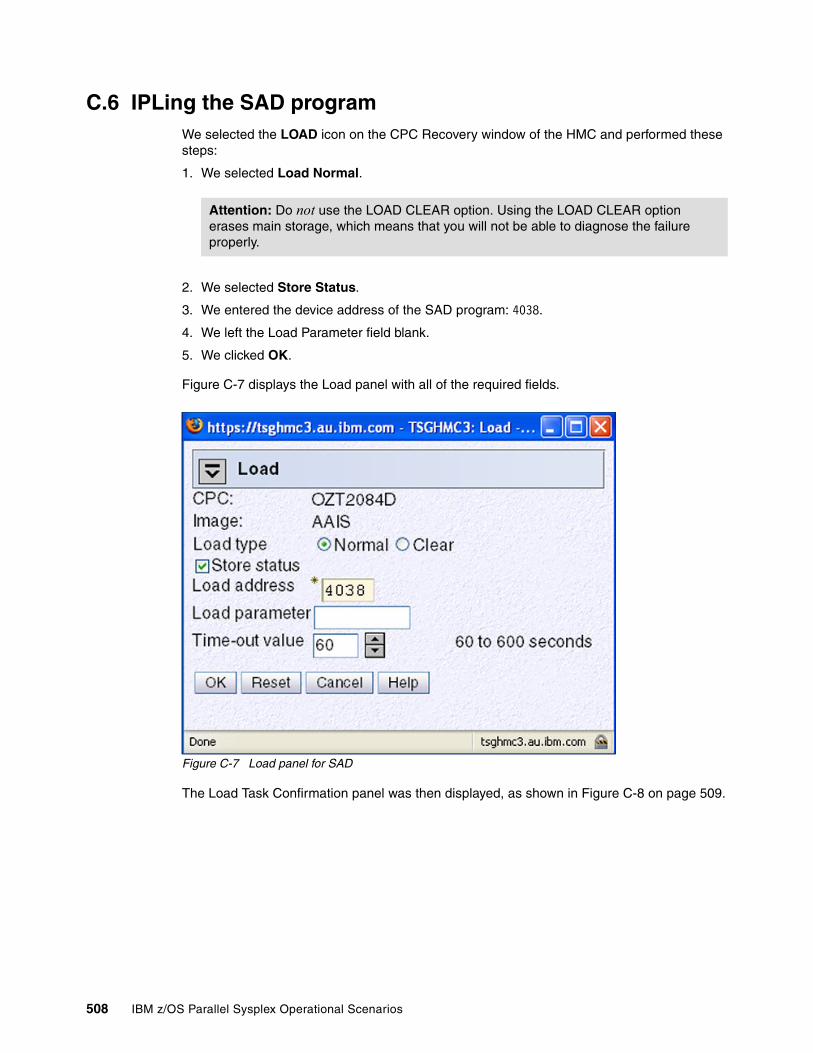
C.6 IPLing the SAD programWe selected the LOAD icon on the CPC Recovery window of the HMC and performed these steps:
1. We selected Load Normal.
2. We selected Store Status.
3. We entered the device address of the SAD program: 4038.
4. We left the Load Parameter field blank.
5. We clicked OK.
Figure C-7 displays the Load panel with all of the required fields.
Figure C-7 Load panel for SAD
The Load Task Confirmation panel was then displayed, as shown in Figure C-8 on page 509.
Attention: Do not use the LOAD CLEAR option. Using the LOAD CLEAR option erases main storage, which means that you will not be able to diagnose the failure properly.
508 IBM z/OS Parallel Sysplex Operational Scenarios

Figure C-8 Load Task Confirmation panel
We clicked Yes on the Load Task Confirmation panel. This was followed by the Load Progress panel, as shown in Figure C-9.
Figure C-9 Load Progress panel
C.7 Sysplex partitioningWhile the SAD IPL was in progress, we received messages on system AAIL, as shown in Figure C-10 on page 510. These messages indicated that sysplex partitioning had started. In response to message IXC402D, we replied DOWN.
Note: We did not need to perform a System Reset of AAIS, because the IPL of the SAD program does this.
Appendix C. Stand-alone dump on a Parallel Sysplex example 509

Figure C-10 Sysplex partitioning during SAD
C.8 Sending a null line on Operating System Messages taskWhen the SAD IPL completed, the Operating System Messages window for AAIS displayed, as shown in Figure C-11.
Figure C-11 Identifying the HMC console to SAD
By issuing V CN(*),ACTIVATE, we identified the HMC console to the SAD program.
C.9 Specifying the SAD output addressThe SAD program then requested the output device address, as shown in Figure C-12 on page 511.
40 IXC402D AAIS LAST OPERATIVE AT 15:42:29. REPLY DOWN AFTER SYSTEM RESET, OR INTERVAL=SSSSS TO SET A REPROMPT TIME.
R 40,DOWN IEE600I REPLY TO 40 IS;DOWN IXC101I SYSPLEX PARTITIONING IN PROGRESS FOR AAIS REQUESTED BY XCFAS. REASON: SYSTEM STATUS UPDATE MISSING IEA257I CONSOLE PARTITION CLEANUP IN PROGRESS FOR SYSTEM AAIS. ISG011I SYSTEM AAIS - BEING PURGED FROM GRS COMPLEX ISG013I SYSTEM AAIS - PURGED FROM GRS COMPLEX IEA258I CONSOLE PARTITION CLEANUP COMPLETE FOR SYSTEM AAIS.
Tip: Issue the V CN(*),ACTIVATE command prior to entering any other commands.
Note: Depending on how your installation has configured the SAD program, you may not receive prompting.
510 IBM z/OS Parallel Sysplex Operational Scenarios
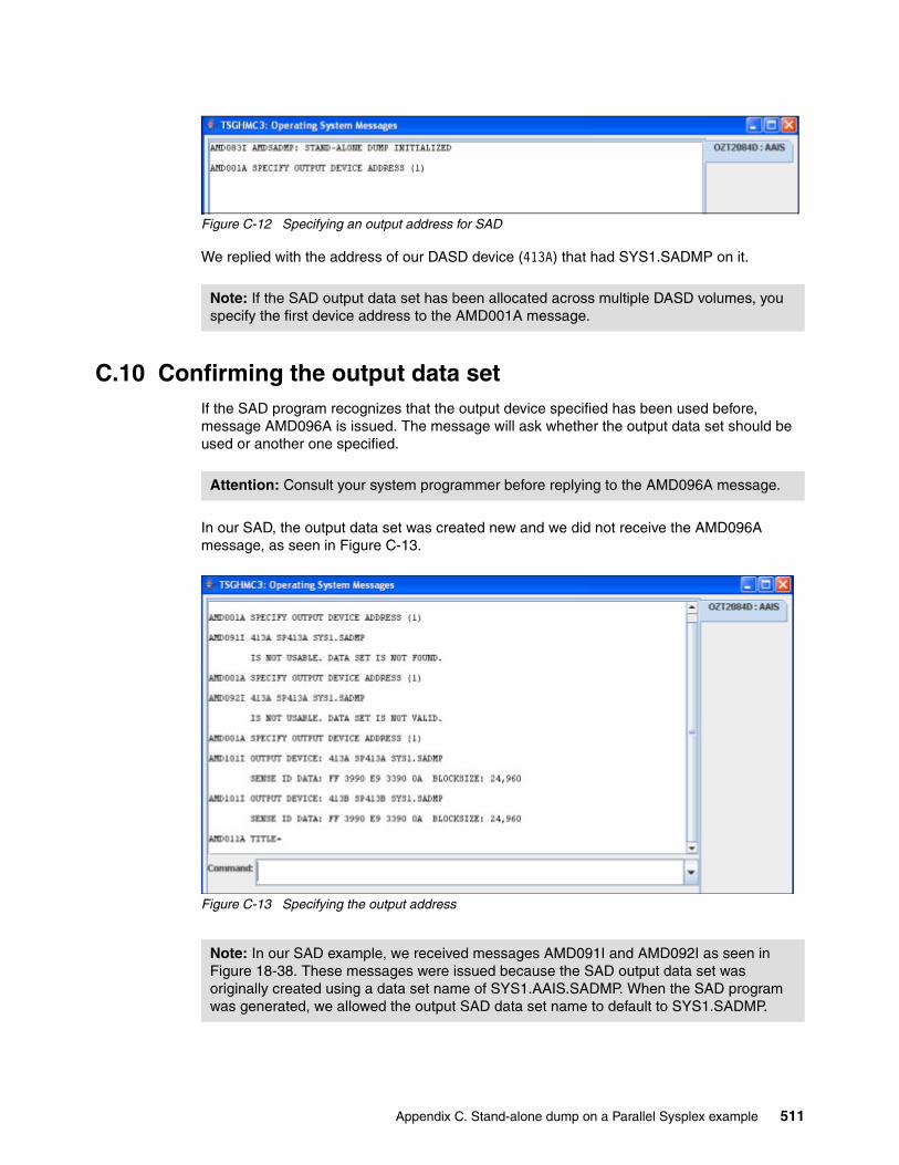
Figure C-12 Specifying an output address for SAD
We replied with the address of our DASD device (413A) that had SYS1.SADMP on it.
C.10 Confirming the output data setIf the SAD program recognizes that the output device specified has been used before, message AMD096A is issued. The message will ask whether the output data set should be used or another one specified.
In our SAD, the output data set was created new and we did not receive the AMD096A message, as seen in Figure C-13.
Figure C-13 Specifying the output address
Note: If the SAD output data set has been allocated across multiple DASD volumes, you specify the first device address to the AMD001A message.
Attention: Consult your system programmer before replying to the AMD096A message.
Note: In our SAD example, we received messages AMD091I and AMD092I as seen in Figure 18-38. These messages were issued because the SAD output data set was originally created using a data set name of SYS1.AAIS.SADMP. When the SAD program was generated, we allowed the output SAD data set name to default to SYS1.SADMP.
Appendix C. Stand-alone dump on a Parallel Sysplex example 511
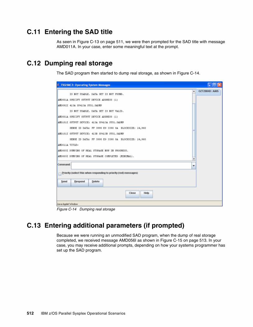
C.11 Entering the SAD titleAs seen in Figure C-13 on page 511, we were then prompted for the SAD title with message AMD011A. In your case, enter some meaningful text at the prompt.
C.12 Dumping real storageThe SAD program then started to dump real storage, as shown in Figure C-14.
Figure C-14 Dumping real storage
C.13 Entering additional parameters (if prompted)Because we were running an unmodified SAD program, when the dump of real storage completed, we received message AMD056I as shown in Figure C-15 on page 513. In your case, you may receive additional prompts, depending on how your systems programmer has set up the SAD program.
512 IBM z/OS Parallel Sysplex Operational Scenarios
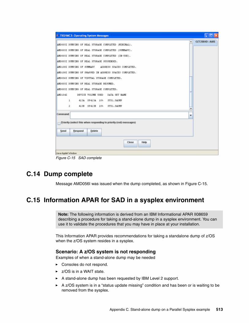
Figure C-15 SAD complete
C.14 Dump completeMessage AMD056I was issued when the dump completed, as shown in Figure C-15.
C.15 Information APAR for SAD in a sysplex environment
This Information APAR provides recommendations for taking a standalone dump of z/OS when the z/OS system resides in a sysplex.
Scenario: A z/OS system is not respondingExamples of when a stand-alone dump may be needed
� Consoles do not respond.
� z/OS is in a WAIT state.
� A stand-alone dump has been requested by IBM Level 2 support.
� A z/OS system is in a “status update missing” condition and has been or is waiting to be removed from the sysplex.
Note: The following information is derived from an IBM Informational APAR II08659 describing a procedure for taking a stand-alone dump in a sysplex environment. You can use it to validate the procedures that you may have in place at your installation.
Appendix C. Stand-alone dump on a Parallel Sysplex example 513
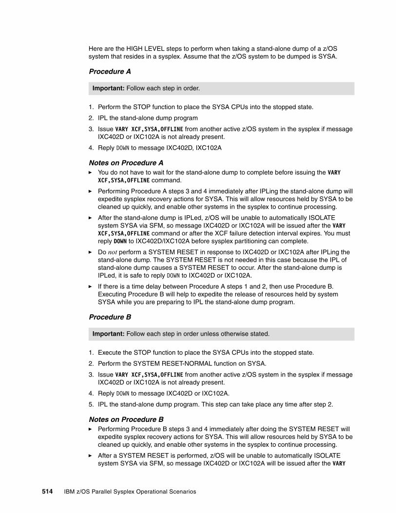
Here are the HIGH LEVEL steps to perform when taking a stand-alone dump of a z/OS system that resides in a sysplex. Assume that the z/OS system to be dumped is SYSA.
Procedure A
1. Perform the STOP function to place the SYSA CPUs into the stopped state.
2. IPL the stand-alone dump program
3. Issue VARY XCF,SYSA,OFFLINE from another active z/OS system in the sysplex if message IXC402D or IXC102A is not already present.
4. Reply DOWN to message IXC402D, IXC102A
Notes on Procedure A� You do not have to wait for the stand-alone dump to complete before issuing the VARY
XCF,SYSA,OFFLINE command.
� Performing Procedure A steps 3 and 4 immediately after IPLing the stand-alone dump will expedite sysplex recovery actions for SYSA. This will allow resources held by SYSA to be cleaned up quickly, and enable other systems in the sysplex to continue processing.
� After the stand-alone dump is IPLed, z/OS will be unable to automatically ISOLATE system SYSA via SFM, so message IXC402D or IXC102A will be issued after the VARY XCF,SYSA,OFFLINE command or after the XCF failure detection interval expires. You must reply DOWN to IXC402D/IXC102A before sysplex partitioning can complete.
� Do not perform a SYSTEM RESET in response to IXC402D or IXC102A after IPLing the stand-alone dump. The SYSTEM RESET is not needed in this case because the IPL of stand-alone dump causes a SYSTEM RESET to occur. After the stand-alone dump is IPLed, it is safe to reply DOWN to IXC402D or IXC102A.
� If there is a time delay between Procedure A steps 1 and 2, then use Procedure B. Executing Procedure B will help to expedite the release of resources held by system SYSA while you are preparing to IPL the stand-alone dump program.
Procedure B
1. Execute the STOP function to place the SYSA CPUs into the stopped state.
2. Perform the SYSTEM RESET-NORMAL function on SYSA.
3. Issue VARY XCF,SYSA,OFFLINE from another active z/OS system in the sysplex if message IXC402D or IXC102A is not already present.
4. Reply DOWN to message IXC402D or IXC102A.
5. IPL the stand-alone dump program. This step can take place any time after step 2.
Notes on Procedure B� Performing Procedure B steps 3 and 4 immediately after doing the SYSTEM RESET will
expedite sysplex recovery actions for SYSA. This will allow resources held by SYSA to be cleaned up quickly, and enable other systems in the sysplex to continue processing.
� After a SYSTEM RESET is performed, z/OS will be unable to automatically ISOLATE system SYSA via SFM, so message IXC402D or IXC102A will be issued after the VARY
Important: Follow each step in order.
Important: Follow each step in order unless otherwise stated.
514 IBM z/OS Parallel Sysplex Operational Scenarios
XCF,SYSA,OFFLINE command or after the XCF failure detection interval expires. You must reply DOWN to IXC402D/IXC102A before sysplex partitioning can complete.
� Both of these procedures emphasize the expeditious removal of the failing z/OS system from the sysplex. If the failed z/OS is not partitioned out of the sysplex promptly, some processing on the surviving z/OS systems might be delayed.
For additional information about stand-alone dump procedures, refer to z/OS V1R8.0 MVS Diagnosis Tool and Service Aids, GA22-7589.
Attention: Do not IPL standalone dump more than once. Doing so will invalidate the dump of z/OS. To restart stand-alone dump processing, perform the CPU RESTART function on the CPU where the stand-alone dump program was IPLed.
Appendix C. Stand-alone dump on a Parallel Sysplex example 515

516 IBM z/OS Parallel Sysplex Operational Scenarios

Related publications
The publications listed in this section are considered particularly suitable for a more detailed discussion of the topics covered in this book.
IBM Redbooks
For information about ordering these publications, see “How to get Redbooks” on page 519. Note that some of the documents referenced here may be available in softcopy only.
� CICS Workload Management Using CICSPlex SM and the z/OS/ESA Workload Manager, GG24-4286
� Getting the Most Out of a Parallel Sysplex, SG24-2073
� DB2 in the z/OS Platform Data Sharing Recovery, SG24-2218
� IMS/ESA Version 6 Guide, SG24-2228
� IMS/ESA Data Sharing in a Parallel Sysplex, SG24-4303
� Automating CICS/ESA Operations with CICSPlex SM and NetView, SG24-4424
� OS/390 z/OS Multisystem Consoles Implementing z/OS Sysplex Operations, SG24-4626
� OS/390 z/OS Parallel Sysplex Configuration Cookbook, SG24-4706
� CICS and VSAM Record Level Sharing: Recovery Considerations, SG24-4768
� JES3 in a Parallel Sysplex, SG24-4776
� IMS/ESA Parallel Sysplex Implementation: A Case Study, SG24-4831
� IMS/ESA Version 6 Shared Queues, SG24-5088
� IMS Primer, SG24-5352
� Merging Systems into a Sysplex, SG24-6818
� Systems Programmer’s Guide to: z/OS System Logger, SG24-6898
� IMS in the Parallel Sysplex Volume I: Reviewing the IMSplex Technology, SG24-6908
� IMS in the Parallel Sysplex Volume II: Planning the IMSplex, SG24-6928
� IMS in the Parallel Sysplex Volume III: IMSplex Implementation and Operations, SG24-6929
� ABCs of z/OS System Programming Volume 9, SG24-6989
� Server Time Protocol Planning Guide, SG24-7280
� Implementing REXX Support in SDSF, SG24-7419
Other publications
These publications are also relevant as further information sources:
� OS/390 Parallel Sysplex Recovery, GA22-7286
� z/OS V1R8.0 MVS Diagnosis Tool and Service Aids, GA22-7589
© Copyright IBM Corp. 2009. All rights reserved. 517
� z/OS UNIX System Services Planning, GA22-7800
� OS/390 z/OS Initialization and Tuning Reference, GC28-1752
� OS/390 z/OS Planning: Global Resource Serialization, GC28-1759
� OS/390 Planning Operations, GC28-1760
� OS/390 z/OS Setting Up a Sysplex, GC28-1779
� OS/390 z/OS System Commands, GC28-1781
� OS/390 z/OS System Messages, Vol 5 (IGD-IZP), GC28-1788
� OS/390 JES2 Commands, GC28-1790
� OS/390 JES2 Initialization and Tuning Guide, GC28-1791
� OS/390 JES3 Commands, GC28-1798
� SmartBatch for OS/390 Customization, GC28-1633
� OS/390 Parallel Sysplex Test Report, GC28-1963
� IBM OMEGAMON z/OS Management Console User’s Guide, GC32-1955
� S/390 9672 Parallel Transaction Server Operations Guide, GC38-3104
� JES2 Initialization and Tuning Guide, SA22-7532
� z/OS JES2 Initialization and Tuning Reference, SA22-7533
� z/OS V1R10.0 JES3 Commands, SA22-7540
� MVS Planning: Operations, SA22-7601
� z/OS V1R10.0 MVS Programming: Sysplex Services Reference, SA22-7618
� z/OS V1R10.0 MVS Setting up a Sysplex, SA22-7625
� z/OS JES2 Commands, SA22-7526
� z/OS MVS System Commands, SA22-7627
� z/OS MVS System Messages Volume 10 (IXC - IZP), SA22-7640
� SDSF Operation and Customization, SA22-7670
� z/OS System Services Command Reference, SA22-7802
� IBM Health Checker for z/OS Users Guide, SA22-7994
� IMS Command Reference Manual V9, SC18-7814
� IMS Common Queue Server Guide and Reference Version 9, SC18-7815
� IMS Common Service Layer Guide and Reference V9, SC18-7816
� IMS Database Recovery Control (DBRC) Guide and Reference Version 9, SC18-7818
� IMS Connect Guide and Reference, Version 9, SC18-9287
� RACF System Programmer’s Guide, SC23-3725
� z/OS Distributed File Service zFS Administration, SC24-5989
� IMS/ESA Operations Guide, SC26-8741
� OS/390 SDSF Guide and Reference, SC28-1622
� OS/390 Security Server (RACF) Command Language Reference, SC28-1919
� Hardware Management Console Operations Guide, SC28-6837
� z/OS V1R8.0 Communications Server: SNA Resource Definition Reference, SC31-8778
� z/OS Communications Server: IP System Administration Commands, SC31-8781
518 IBM z/OS Parallel Sysplex Operational Scenarios

� IBM Press publication An Introduction to IMS, 2004, ISBN 0131856715
� Parallel Sysplex Performance: XCF Performance Considerations white paper
http://www.ibm.com/support/techdocs/atsmastr.nsf/WebIndex/WP100743/
Online resources
These Web sites are also relevant as further information sources:
� IBM homepage for Parallel Sysplex
http://www.ibm.com/systems/z/advantages/pso/index.html/
How to get Redbooks
You can search for, view, or download Redbooks, Redpapers, Technotes, draft publications and Additional materials, as well as order hardcopy Redbooks publications, at this Web site:
ibm.com/redbooks
Help from IBM
IBM Support and downloads
ibm.com/support
IBM Global Services
ibm.com/services
Related publications 519

520 IBM z/OS Parallel Sysplex Operational Scenarios
Index
Numerics0A2 Wait State 669037 32
Aabnormal stop 68action message retention facility (AMRF) 297adding
a system image to a Parallel Sysplex 50CF 120
alerts 304applications
critical 84ARM 252
automation 84cancelling with ARMRESTART parameter 98changing ARM policy 90CICS 362cross-system restarts 100defining RRS 481description 84operating with ARM 98policies 90, 425policy management 90restrictions 99same system restarts 98starting ARM policy 90
ARM (see Automatic Restart Manager) 394ARM Couple Data Set 7ARMRESTART 94ARMWRAP 96ATRHZS00 479AUTOEMEM 26automated monitoring 14Automatic Restart Manager (ARM) 7, 84, 394
ARM 25IMS 421WebSphere MQ 466
automationARM 99
automove 488
Bbase sysplex
definition 2Batch Message Processing (BMP) region 403BronzePlex 9buffer
coherency 5Business Application Services (BAS) 365
Ccache structure 8Cache structure (GBPs) 369capacity
unused 4capping 124CDS 23CF 368
CICS 351data tables
CICS 355DB2 369failure 22
CICS recovery 352IMS 413locking 390log stream 309outages 9physical information 15receiver (CFR) 16role in locking 5role in maintaining buffer coherency 5sender (CFS) 16structure 184structures 9, 22, 105VTAM 326
CFRMCDS allocation during IPL 45Couple Data Set 9initialization 46policies 85, 115policy 9, 21
Channel-to-Channel adapter (CTC) 6, 184checkpoint data set (CQS) 415CICS
APPLID 346ARM 362CF 351CF data tables 355CICSPlex 364co-existing with IMS 400commands for generic resources 333deregister from a generic resource group 333interregion communication (IRC) 347introduction 346journal 348log 348managing generic resources 333named counter server 359remove from a generic resource group 333shared temporary storage 352transaction routing 348VTAM 347with IMS DB 398
Index 521
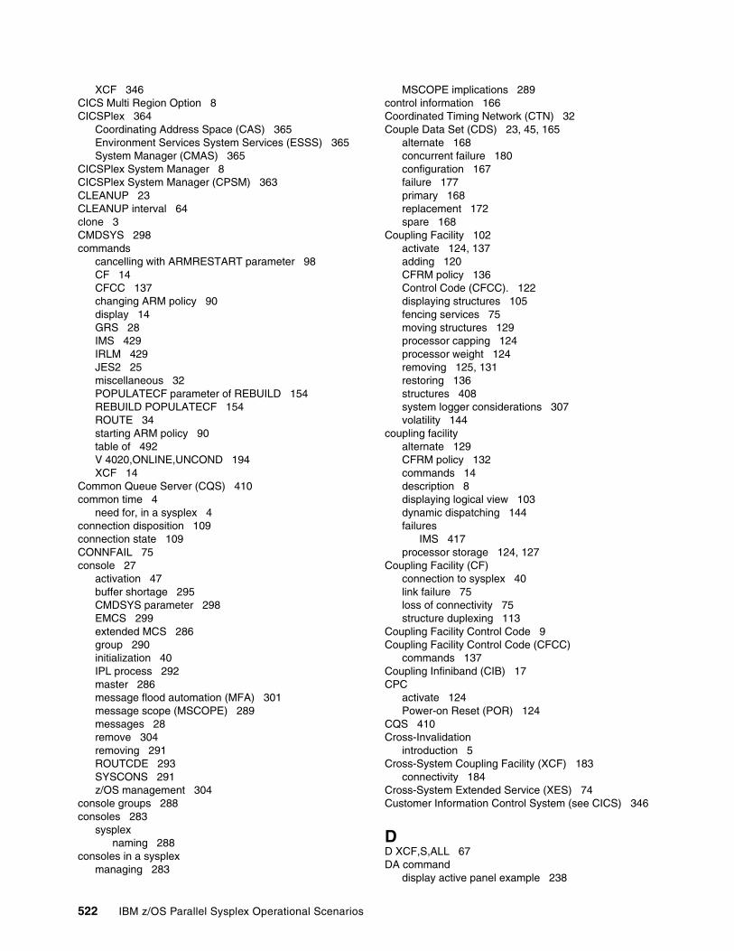
XCF 346CICS Multi Region Option 8CICSPlex 364
Coordinating Address Space (CAS) 365Environment Services System Services (ESSS) 365System Manager (CMAS) 365
CICSPlex System Manager 8CICSPlex System Manager (CPSM) 363CLEANUP 23CLEANUP interval 64clone 3CMDSYS 298commands
cancelling with ARMRESTART parameter 98CF 14CFCC 137changing ARM policy 90display 14GRS 28IMS 429IRLM 429JES2 25miscellaneous 32POPULATECF parameter of REBUILD 154REBUILD POPULATECF 154ROUTE 34starting ARM policy 90table of 492V 4020,ONLINE,UNCOND 194XCF 14
Common Queue Server (CQS) 410common time 4
need for, in a sysplex 4connection disposition 109connection state 109CONNFAIL 75console 27
activation 47buffer shortage 295CMDSYS parameter 298EMCS 299extended MCS 286group 290initialization 40IPL process 292master 286message flood automation (MFA) 301message scope (MSCOPE) 289messages 28remove 304removing 291ROUTCDE 293SYSCONS 291z/OS management 304
console groups 288consoles 283
sysplexnaming 288
consoles in a sysplexmanaging 283
MSCOPE implications 289control information 166Coordinated Timing Network (CTN) 32Couple Data Set (CDS) 23, 45, 165
alternate 168concurrent failure 180configuration 167failure 177primary 168replacement 172spare 168
Coupling Facility 102activate 124, 137adding 120CFRM policy 136Control Code (CFCC). 122displaying structures 105fencing services 75moving structures 129processor capping 124processor weight 124removing 125, 131restoring 136structures 408system logger considerations 307volatility 144
coupling facilityalternate 129CFRM policy 132commands 14description 8displaying logical view 103dynamic dispatching 144failures
IMS 417processor storage 124, 127
Coupling Facility (CF)connection to sysplex 40link failure 75loss of connectivity 75structure duplexing 113
Coupling Facility Control Code 9Coupling Facility Control Code (CFCC)
commands 137Coupling Infiniband (CIB) 17CPC
activate 124Power-on Reset (POR) 124
CQS 410Cross-Invalidation
introduction 5Cross-System Coupling Facility (XCF) 183
connectivity 184Cross-System Extended Service (XES) 74Customer Information Control System (see CICS) 346
DD XCF,S,ALL 67DA command
display active panel example 238
522 IBM z/OS Parallel Sysplex Operational Scenarios

Data Entry Data Base Virtual Storage Option (DEDB VSO) 414data sharing 5, 367, 406
DB2 131IMS 131RACF 133
database managermultiple instances 5
database sharingIMS 401
DB2 367–368CF 368–369data sharing 131, 367GBP user-managed duplexing 371intersystem resource lock manager 368introduction 368lock structures 391restart light 393structure 369
DBCTL 398DBRC (IMSDBRC) 403DCCTL
IMS TM with DB2 399determining
Automatic Restart Manager status 25CF names and node descriptor 15names of all structures defined in the CFRM policy 19number and names of CFs 15number and names of systems in the sysplex 14number and types of Couple Data Sets 23physical information about the CF 15system status 14which structures are in each CF 15
DEVSERV 29DFHLOG 349DFHSHUNT 349DISPLAY command
D NET,STATS,CFS 331displaying system logger status 310
display command 14DLI Separate Address Space (DLISAS) 403DUPLEX keyword 115duplexing 371, 474, 478
IMS 416system-managed 114user-managed 114
dynamic system interchange (DSI) 276dynamic workload balancing 7
Eelement 466EMCS console 299ETR
mode 31Event Notification Facility (ENF) 310Expedited Message Handler Queue (EMHQ) structure 415exploiting installed capacity 4extended MCS (EMCS) consoles 287extended MCS consoles 286
External Timer References 31
Ffailed-persistent state 326failure
CF 22IPL failure scenarios 52processor 443
Failure Detection Interval 6failure management
restart management 3Fast Path databases 406fencing 64, 75
GGeneric Resources 324, 402
CICS 333managing 330TSO 334
Global Resource Serialization (GRS) 8, 28initialization 40
Global Resource Sharing (GRS)initialization 47
GoldPlex 10Group Buffer Pool (GBP) 369GRS
commands 28description 8ring initialization in first IPL 47
HHardware Management Console (HMC) 102, 122, 291
image profile 122reset profile 122
health check 304Health Checker 258
RRS 479HFS 485HFSplex 487Hierarchical File System (HFS) 485HMC
SAD 503HZSPRINT 266HZSPROC 258
IIBM Tivoli OMEGAMON z/OS Management Console 304IEARELCN 304IEARELEC 304IEECMDPF program to create command prefixes 35IEEGSYS 300IMS
ARM 421CF failures 417CF structures 408, 413Connect 323data sharing 131, 405–406data sharing with shared queues 409
Index 523
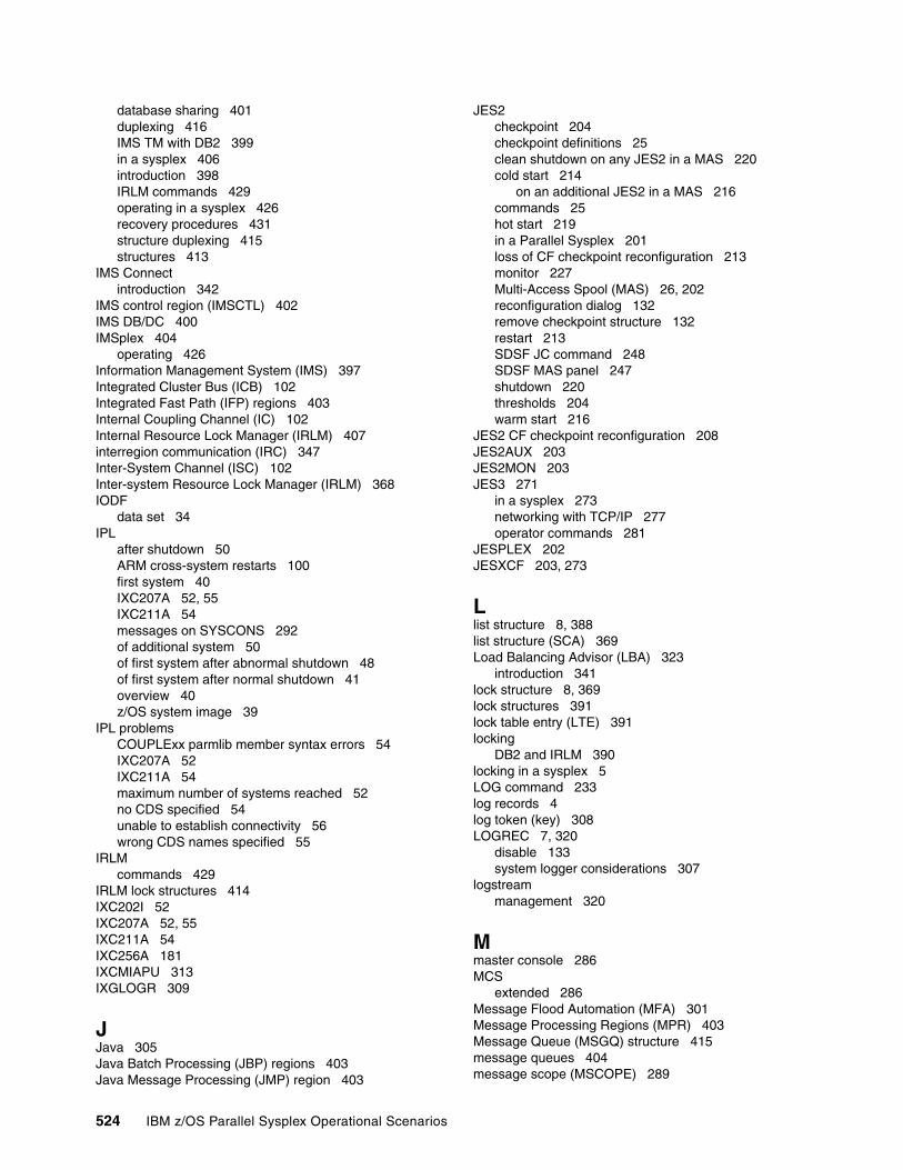
database sharing 401duplexing 416IMS TM with DB2 399in a sysplex 406introduction 398IRLM commands 429operating in a sysplex 426recovery procedures 431structure duplexing 415structures 413
IMS Connectintroduction 342
IMS control region (IMSCTL) 402IMS DB/DC 400IMSplex 404
operating 426Information Management System (IMS) 397Integrated Cluster Bus (ICB) 102Integrated Fast Path (IFP) regions 403Internal Coupling Channel (IC) 102Internal Resource Lock Manager (IRLM) 407interregion communication (IRC) 347Inter-System Channel (ISC) 102Inter-system Resource Lock Manager (IRLM) 368IODF
data set 34IPL
after shutdown 50ARM cross-system restarts 100first system 40IXC207A 52, 55IXC211A 54messages on SYSCONS 292of additional system 50of first system after abnormal shutdown 48of first system after normal shutdown 41overview 40z/OS system image 39
IPL problemsCOUPLExx parmlib member syntax errors 54IXC207A 52IXC211A 54maximum number of systems reached 52no CDS specified 54unable to establish connectivity 56wrong CDS names specified 55
IRLMcommands 429
IRLM lock structures 414IXC202I 52IXC207A 52, 55IXC211A 54IXC256A 181IXCMIAPU 313IXGLOGR 309
JJava 305Java Batch Processing (JBP) regions 403Java Message Processing (JMP) region 403
JES2checkpoint 204checkpoint definitions 25clean shutdown on any JES2 in a MAS 220cold start 214
on an additional JES2 in a MAS 216commands 25hot start 219in a Parallel Sysplex 201loss of CF checkpoint reconfiguration 213monitor 227Multi-Access Spool (MAS) 26, 202reconfiguration dialog 132remove checkpoint structure 132restart 213SDSF JC command 248SDSF MAS panel 247shutdown 220thresholds 204warm start 216
JES2 CF checkpoint reconfiguration 208JES2AUX 203JES2MON 203JES3 271
in a sysplex 273networking with TCP/IP 277operator commands 281
JESPLEX 202JESXCF 203, 273
Llist structure 8, 388list structure (SCA) 369Load Balancing Advisor (LBA) 323
introduction 341lock structure 8, 369lock structures 391lock table entry (LTE) 391locking
DB2 and IRLM 390locking in a sysplex 5LOG command 233log records 4log token (key) 308LOGREC 7, 320
disable 133system logger considerations 307
logstreammanagement 320
Mmaster console 286MCS
extended 286Message Flood Automation (MFA) 301Message Processing Regions (MPR) 403Message Queue (MSGQ) structure 415message queues 404message scope (MSCOPE) 289
524 IBM z/OS Parallel Sysplex Operational Scenarios
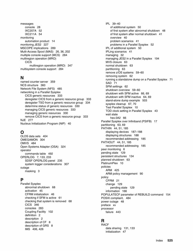
messagesconsole 28IXC207A 52IXC211A 54
monitoringautomation product 14
monitoring JES2 227MSCOPE implications 289Multi-Access Spool (MAS) 26, 36, 202multiple console support (MCS) 284multiregion operation (MRO)
CICSmultiregion operation (MRO) 347
multisystem console support 284
Nnamed counter server 359NCS structure 360Network File System (NFS) 485networking in a Parallel Sysplex
CICS generic resources 333deregister CICS from a generic resource group 333deregister TSO from a generic resource group 334determine status of generic resources 330managing CICS generic resources 333managing generic resources 330remove CICS from a generic resource group 333
NJE 277Nucleus Initialization Program (NIP) 40
OOLDS data sets 404OMEGAMON 304OMVS 484Open Systems Adapter (OSA) 324operator
commands table 492OPERLOG 7, 133, 233
SDSF OPERLOG panel 235system logger considerations 307
outagemasking 3
PParallel Sysplex
abnormal shutdown 68activation 45CFRM initialization 46checking if SFM is active 61checking that system is removed 68CICS 346consoles 283Coupling Facility 102definition 2description 2description of CF 8description of GRS 8IMS 406, 426
IPL 39–40of additional system 50of first system after abnormal shutdown 48of first system after normal shutdown 41overview 40problem scenarios 41problems in a Parallel Sysplex 52
IPL of additional system 50IPLing scenarios 41managing 32managing JES2 in a Parallel Sysplex 194MVS closure 63normal shutdown 63partitioning 63remove z/OS systems 59–60removing system 62running a standalone dump on a Parallel Sysplex 71SAD 71SFM settings 62shutdown overview 59–60shutdown with SFM active 66, 69shutdown with SFM inactive 64, 69stand-alone dump example 503sysplex cleanup 67, 70Test Parallel Sysplex 10TOD clock setting in Parallel Sysplex 43wait state
hex.0A2 66Parallel Sysplex over Infiniband (PSIFB) 17partitioning 63, 69PATHIN 44, 51, 185
displaying devices 187–188displaying structures 188recommended addressing 185
PATHOUT 44, 51, 185recommended addressing 185
peer monitoring 6pending state 129persistent structures 134planned shutdown 63PlatinumPlex 10policies
ARM 425ARM policy management 90
policyCFRM 21change 129
pending state 129information 166
POPULATECF parameter of REBUILD command 154POSIX compliant, 484power outage 48preface xvprocessor
failure 443
RRACF
data sharing 131, 133initialization 47
Index 525
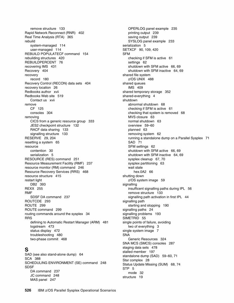
remove structure 133Rapid Network Reconnect (RNR) 402Real Time Analysis (RTA) 365rebuild
system-managed 114user-managed 114
REBUILD POPULATECF command 154rebuilding structures 420REBUILDPERCENT 76recovering IMS 431Recovery 404recovery
record 180Recovery Control (RECON) data sets 404recovery location 26Redbooks author xviiRedbooks Web site 519
Contact us xviiremove
CF 125consoles 304
removingCICS from a generic resource group 333JES2 checkpoint structure 132RACF data sharing 133signalling structure 133
RESERVE 29, 204resetting a system 65resource
contention 30serialization 5
RESOURCE (RES) command 251Resource Measurement Facility (RMF) 237resource monitor (RM) command 246Resource Recovery Services (RRS) 468resource structure 415restart light
DB2 393REXX 255RMF
SDSF DA command 237ROUTCDE 293ROUTE 299ROUTE command 299routing commands around the sysplex 34RRS
defining to Automatic Restart Manager (ARM) 481logstream 473status display 472troubleshooting 480two-phase commit 468
SSAD (see also stand-alone dump) 64SCA 388SCHEDULING ENVIRONMENT (SE) command 248SDSF
DA command 237JC command 248MAS panel 247
OPERLOG panel example 235printing output 239saving output 239SYSLOG panel example 233
serialization 5SETXCF 90, 109, 420SFM
checking if SFM is active 61settings 62shutdown with SFM active 66, 69shutdown with SFM inactive 64, 69
shared file systemz/OS UNIX 488
shared queuesIMS 409
shared temporary storage 352shared-everything 4shutdown
abnormal shutdown 68checking if SFM is active 61checking that system is removed 68MVS closure 63normal shutdown 63overview 59–60planned 63removing system 62running a standalone dump on a Parallel Sysplex 71SAD 71SFM settings 62shutdown with SFM active 66, 69shutdown with SFM inactive 64, 69sysplex cleanup 67, 70sysplex partitioning 63wait state
hex.0A2 66shutting down
z/OS system image 59signalling
insufficent signalling paths during IPL 56remove structure 133signalling path activation in first IPL 44
signalling pathstarting and stopping 190
signalling paths 24signalling problems 193SIMETRID 55single points of failure, avoiding
two of everything 3single system image 7SNA
Generic Resources 324SNA MCS (SMCS) consoles 287staging data sets 478stalled member 197standalone dump (SAD) 59–60, 71Star complex 28Status Update Missing (SUM) 68, 74STP 5
mode 32structure 19
526 IBM z/OS Parallel Sysplex Operational Scenarios
allocation 45cache 369DB2 368–369duplexing
system-managed 113list 369list (SCA) 388lock 369NCS 360rebuilding 420resource 415WebSphere MQ 464
structure full monitoring 119Structure Recovery Data Sets (SRDS) 415structures 9
as possible cause of IPL problem 56CF 22, 105
IMS 408connection state 109disposition 109during CFRM initialization 46generic resources 330IMS 413list of 499managing CF 147move to alternate CF 129rebuild failure 161rebuilding 147rebuilding in another CF 152rebuilding in either CF 148remove JES2 checkpoint structure 132remove LOGREC 133remove OPERLOG 133remove RACF data sharing 133remove signalling 133signalling structures during first IPL 44stopping rebuild 161that support rebuild, rebuilding of 147
symbol 36sympathy sickness 76SYSCONS 291SYSLOG 133, 233sysplex 27, 286
console 27DB2 394definition 2environment 2GoldPlex 10IMS 406JES3 273master console 286partitioning 63PlatinumPlex 10sympathy sickness 76three-way 11timer 31
Sysplex Couple Data Set 6sysplex couple dataset (CDS) 74Sysplex Distributor 323
introduction 339
Sysplex Failure Management 6Sysplex Failure Management (SFM) 61, 74sysplex time management
TOD clock setting in Parallel Sysplex 43system
affinity 226group name 300logger 307recovery 3
System Display and Search Facility (SDSF) 232system failure
JES3 actions 276System Health Checker 252System Logger 7system logger 348
address space 309directory extents 317displaying system logger status 310ENQ serialization 317offload monitoring 316remove 133removing structures 133structure rebuilds 319system logger considerations 307
System Network Architecture (SNA) 324SYSTEM RESET 65system symbol 36System z file system (zFS) 486System-managed Coupling Facility (CF)
structure duplexing 113
TTCP Sysplex Distributor 7TCP/IP 277, 323
commands 338introduction 336
test environmentz/VM 11
three-way sysplex 11time
common 4consistency 5
time zoneoffset setting 43
Time-Of-Day (TOD)clock setting 43
Tivoli Enterprise Portal 305transaction processing (TP) 346transaction routing 348transport class 192troubleshooting
RRS 480TSO
deregister from a generic resource group 334monitoring a sysplex 36
two-phase commit 468
UULOG command 235
Index 527
UNIX shell environment (OMVS) 484user-managed duplexing 371USRJRNL 350
Vvalue-for-money 4VARY command
V 4020,ONLINE,UNCOND 194VARY XCF 74Virtual IP Address (VIPA), dynamic
dynamic VIPA 339Virtual Telecommunications Access Method (VTAM) 323volatility 478VSAM
cache structures 414VTAM 347
CF 326Generic Resources 324
VTAM Generic Resources 7VTAM in a Parallel Sysplex
CICS generic resources 333commands for generic resources 330deregister CICS from a generic resource group 333deregister TSO from a generic resource group 334determine status of generic resources 330managing CICS generic resources 333managing generic resources 330remove CICS from a generic resource group 333
WWADS data sets 404WebSphere MQ
Automatic Restart Manager (ARM) 466commands 462introduction 456ISPF panels 461monitoring 461structure 464
WEIGHT 75WLM
policies 85Work Context 468Workload Manager (WLM) 7, 366
XXCF 6, 489
CICS 346commands 14connectivity, unable to establish 56initialization 40signalling 184signalling paths 24signalling services 6, 194stalled member detection 197starting 46XCF initialization in IPL 44XCF initialization restarted in failed IPL 52
XCF/MRO 347
XES 102, 113, 416
Zz/OS
system log 233z/OS Health Checker 258z/OS Management Console 304z/OS UNIX
files 487introduction 484
z/VMtest environment 11
zFS 486administration 489
528 IBM z/OS Parallel Sysplex Operational Scenarios

(1.0” spine)0.875”<
->1.498”
460 <->
788 pages
IBM z/OS Parallel Sysplex Operational Scenarios
IBM z/OS Parallel Sysplex
Operational Scenarios
IBM z/OS Parallel Sysplex
Operational Scenarios
IBM z/OS Parallel Sysplex Operational Scenarios

IBM z/OS Parallel Sysplex
Operational Scenarios
IBM z/OS Parallel Sysplex
Operational Scenarios

®
SG24-2079-01 ISBN 0738432687
INTERNATIONAL TECHNICALSUPPORTORGANIZATION
BUILDING TECHNICAL INFORMATION BASED ON PRACTICAL EXPERIENCE
IBM Redbooks are developed by the IBM International Technical Support Organization. Experts from IBM, Customers and Partners from around the world create timely technical information based on realistic scenarios. Specific recommendations are provided to help you implement IT solutions more effectively in your environment.
For more information:ibm.com/redbooks
®
IBM z/OS Parallel SysplexOperational Scenarios
Understanding Parallel Sysplex
Handbook for sysplex management
Operations best practices
This IBM Redbooks publication is a major update to the Parallel Sysplex Operational Scenarios book, originally published in 1997.
The book is intended for operators and system programmers, and is intended to provide an understanding of Parallel Sysplex operations. This understanding, together with the examples provided in this book, will help you effectively manage a Parallel Sysplex and maximize its availability and effectiveness.
The book has been updated to reflect the latest sysplex technologies and current recommendations, based on the experiences of many sysplex customers over the last 10 years.
It is our hope that readers will find this to be a useful handbook for day-to-day sysplex operation, providing you with the understanding and confidence to expand your exploitation of the many capabilities of a Parallel Sysplex.
Knowledge of single-system z/OS operations is assumed. This book does not go into detailed recovery scenarios for IBM subsystem components, such as CICS Transaction Server, DB2 or IMS. These are covered in great depth in other Redbooks publications.
Back cover