Embed Size (px)
Citation preview
MOSTMaynard Operation Sequence
Technique
Work Measurement System
By Yogesh Nakhate
Methods - Time Measurement
H. B. Maynard was one of three persons instrumental in the creation
of MTM.
Kjell Zandin, while working in the Swedish Division of H. B. Maynard in the late 1960’s,
detected striking similarities in the sequence of MTM defined
motions whenever an object was handled.
Under MOST, the primary work units are no longer basic motions
as in MTM, but collections of these basic motions dealing with
moving object.
MOST makes the assumption that to move an object, a standard
sequence of events occurs.
Under MOST, objects can be moved in only one of two ways:
• They are picked up and moved freely through space -- the GENERAL MOVE.
• They are moved and maintain contact with another surface -- the CONTROLLED MOVE.
The MOST Family
• Basic MOST -- General Operations
• Mini MOST -- Repetitive Operations
• Maxi MOST -- Non-repetitive Operations
• Clerical MOST -- Clerical Operations
Maxi MOST is used to analyze operations that are likely to be
performed less than 150 times per week.
Basic MOST is used for operations that are likely to be performed more than 150 times
but less than 1500 times per week.
Mini MOST is used to analyze operations likely to be repeated more than 1500 times per week.
The Decision Diagram provides a simple procedure for selecting the
most appropriate MOST Work Measurement System to use.
The MOST Decision Diagram is based on +/- 5% accuracy and a
95% confidence level.
System Selection Charts may be used in lieu of the Decision
Diagram for choosing the best MOST Work Measurement
System to use.
The MOST Standard Form provides the analyst with a
simple, consistent format for analyzing work using the method.
It should be possible to complete a MOST analysis by observing two complete cycles of work in
slow motion.
If the method is well established and the analyst knows the
operation and conditions, the Basic MOST calculations can be made from the office and used to
predict the times for a new procedure.
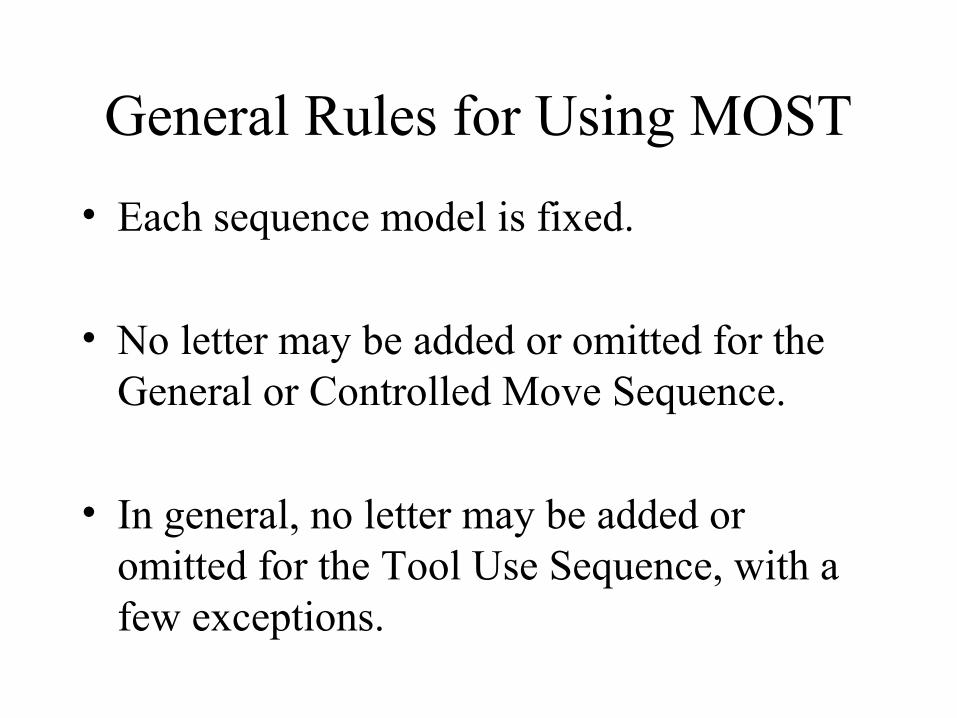
General Rules for Using MOST
• Each sequence model is fixed.
• No letter may be added or omitted for the General or Controlled Move Sequence.
• In general, no letter may be added or omitted for the Tool Use Sequence, with a few exceptions.
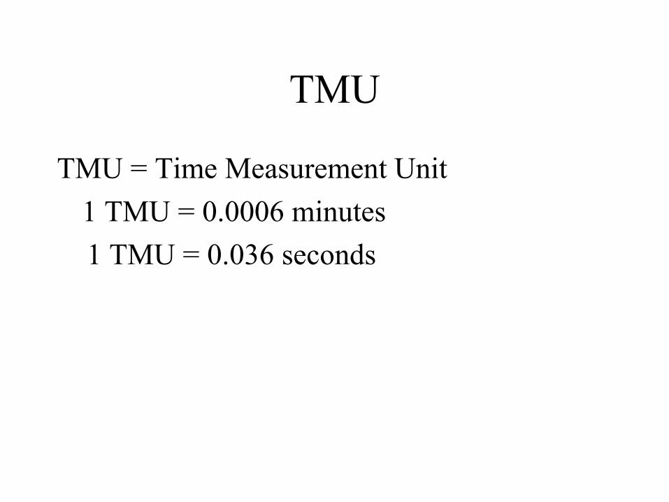
TMU
TMU = Time Measurement Unit
1 TMU = 0.0006 minutes
1 TMU = 0.036 seconds
How it works
• The purpose of the MOST system is to calculate the cycle time for an operation based on Pre-determined time study data.
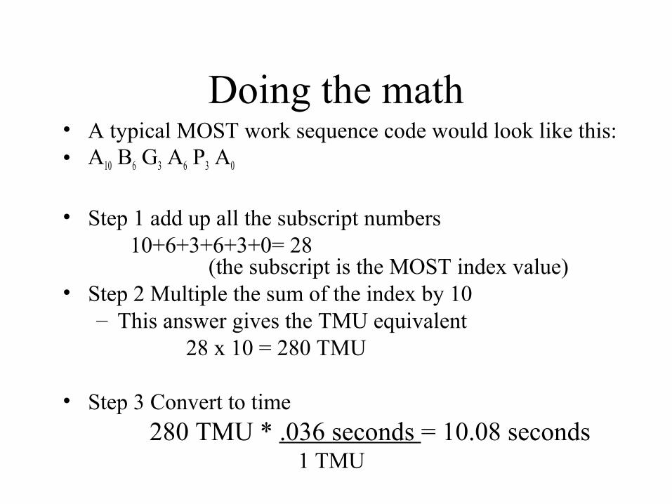
Doing the math• A typical MOST work sequence code would look like this:• A10 B6 G3 A6 P3 A0
• Step 1 add up all the subscript numbers 10+6+3+6+3+0= 28
(the subscript is the MOST index value)• Step 2 Multiple the sum of the index by 10
– This answer gives the TMU equivalent 28 x 10 = 280 TMU
• Step 3 Convert to time 280 TMU * .036 seconds = 10.08 seconds
1 TMU
General Move
Sequence
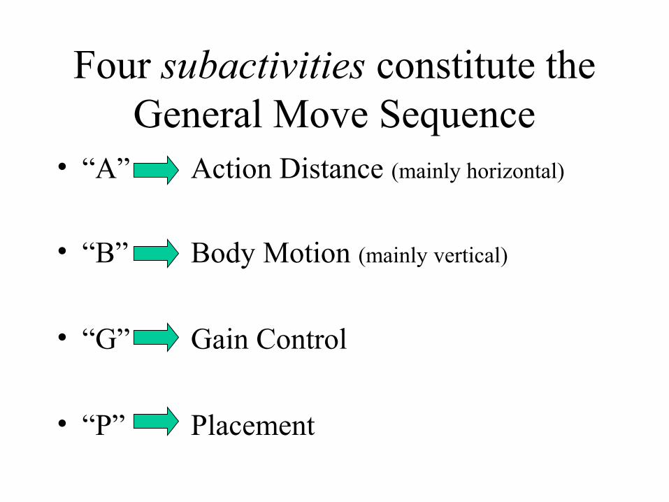
Four subactivities constitute the General Move Sequence
• “A” Action Distance (mainly horizontal)
• “B” Body Motion (mainly vertical)
• “G” Gain Control
• “P” Placement
Roughly 50% of all manual work occurs as a General Move.
The percentage runs higher for assembly and material handling
and lower for machine shop operations.
The General Move follows a fixed sequence of steps:
• Reach, either directly or in conjunction with body motions or steps.
• Gain control of the object.
• Move the object, as in “reach”.
• Place the object in temporary or final position.
• Return to the workplace.
The General Move Sequence Model
A B G A B P A
Action Distance (A)
This parameter is used to analyze all spatial movement or actions of the
fingers, hands, and/or feet.
A0 < 2 Inches
This is any displacement of the fingers, hands, and/or feet a distance
of 2 inches or less.
A1 Within Reach
Actions that are confined to an area described by the arc of the
outstretched arm pivoted about the shoulder.
A3 One to Two Steps
The trunk of the body is shifted or displaced by walking, stepping to the
side, or turning the body around using 1 or 2 steps.
More Than 2 Steps
Used with Action Distance data table to cover longer movements.
Body Motion (B)
This parameter is used to analyze either vertical motions of the body or the actions necessary to overcome an
obstruction or impairment to body movement.
B3 -- Bend & Arise, 50% Occurrence
Bend & Arise is required only 50% of the time during a repetitive activity.
B3 -- Sit or Stand without Moving Chair
When the body is simply lowered into a chair from an erect position,
without hand/foot motions required to manipulate the chair.
B6 -- Bend & Arise
From an erect standing position, the trunk of the body is lowered by
bending from the waist and/or knees to allow the hands to reach below the
knees.
B10 -- Sit or Stand
A series of several hand, foot, and body motions to move a stool / chair into position followed by the body
sitting or standing.
B16 -- Stand and Bend
This is a case where a sitting person must stand up and walk to a location to gain control of an object placed below knee level, where a Bend &
Arise is required.
B16 -- Bend & Sit
This applies when gaining control of an object requires a Bend & Arise
followed by a Sit prior to placing the object.
B16 -- Climb On or Off
This parameter variant covers climbing on or off a work platform on
any raised surface (~3 ft) using a series of hand and body motions to
lift or lower the body.
B16 -- Passing Through Door
Passing through a door consists of reaching for and turning the handle, opening the door, walking through the door, and subsequently closing
the door.
Gain Control (G)
This parameter is used to analyze all manual motions employed to obtain
complete manual control of an object(s) and to subsequently
relinquish that control.
G1 -- Light Object
Gain control of an object by grasping it as long as no difficulty is
encountered.
G1 -- Light Objects Simo
One hand gains control of a light object while the other hand obtains
another light object.
G3 -- Light Object(s) Non-Simo
While one hand is grasping an object, the other hand must wait before it can
grasp the other object.
G3 -- Heavy or Bulky
In grasping a heavy or bulky object there is a delay between when the
object is grasped and when it begins to move due to weight, bulk, etc.
G3 -- Blind or Obstructed
Access to the object is restricted because an obstacle prevents the
operator from seeing the object or creates an obstruction to the
hand/fingers in attempting to gain control.
G3 -- Disengage
An application of muscular force to free an object from its surroundings
typified by a need to overcome resistance followed by sudden
movement and recoil of the object.
G3 -- Interlocked
Interlocked means the object is intermingled or tangled with other objects and must be separated or
worked free before reaching control.
G3 -- Collect
Gain control of several objects jumbled together in a pile or spread
out on a surface.
Placement (P)
This parameter is used to analyze actions at the final stage of an
object’s displacement to align, orient, and/or engage the object with other object(s) before control of the object
is relinquished.
P0 -- Pickup Objects
This is “placement” in which no placement occurs. The object is
picked up and held.
P0 -- Toss Object(s)
Another “placement” where placement does not occur. The object
is released during the “action distance” (A) parameter without
placing motions or pause to point the object toward the target.
P1 -- Lay Aside
The object is placed in an appropriate locations with no apparent aligning or
adjusting motions.
P1 -- Loose Fit
The object is placed in a more specific location than described by the Lay Aside parameter, but with
tolerances so loose that only a modest amount of control is needed for
placement.
P3 -- Adjustments
Adjustments are defined as the corrective actions occurring at the point of placement, and recognized by obvious efforts, hesitations, or correcting motions to align, orient,
and/or engage the object.
P3 -- Light Pressure
Because of close tolerances or the nature of the placement, the
application of muscular force is needed to seat the object.
P3 -- Double
With “double”, two distinct phases occur during the total placing
activity.
P3 -- Loose Fit Blind
In this case the operator must feel around for the placement location
before a loose placement can occur.
P6 -- Care or Precision
Extreme care is needed to place an object within a closely defined
relationship with another object, and characterized by the obvious slow motion of the placement due to the
high degree of concentration required.
P6 -- Heavy Pressure
As a result of very tight tolerances, a high degree of muscular force is
needed to engage the object.
P6 -- Blind or Obstructed
Accessibility to the point of placement is restricted because an
obstacle prevents the operator from seeing the point of placement, or
creates an obstruction to the hand/fingers when attempting to
place the object.
P6 -- Intermediate Moves
Several intermediate moves of the object are required prior to placing.
General Move Example
From a stack located 10 feet away, a heavy object must be picked up and moved 5 feet and placed on top of a workbench with some adjustments.
General Move Example
An assembly worker gets a handful of washers (6) from a bin located within
reach and puts one on each of six bolts located within reach, which are
four inches apart.
General Move Example
A worker gains control of two fittings that are within reach and located
more than two inches apart, one at a time, and places them on separate
trays that are within reach and located less than 2 inches apart.
Controlled Move
Sequence
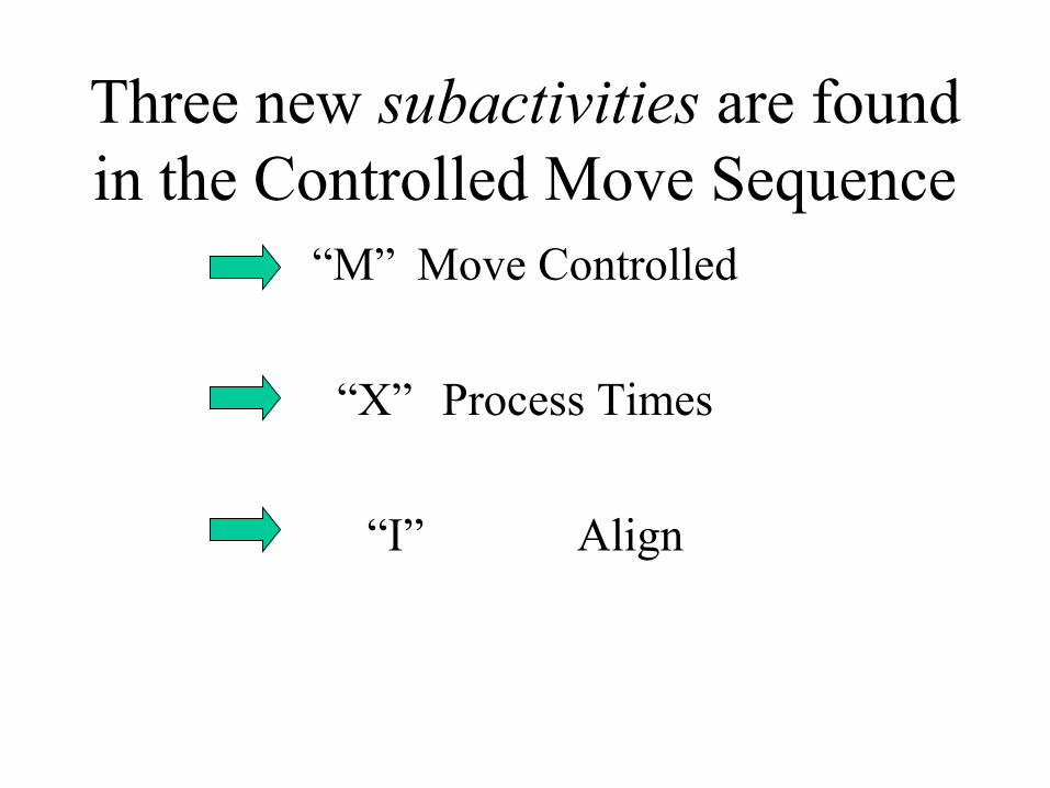
Three new subactivities are found in the Controlled Move Sequence
“M” Move Controlled
“X” Process Times
“I” Align
The Controlled Move Sequence describes the manual
displacement of an object over a “controlled” path.
The Controlled Move follows a fixed sequence of steps:
Reach, either directly or in conjunction with body motions or steps.
Gain control of the object.
Move the object over a controlled path.
Allow time for the process to occur.
Align the object after the move/process.
Return to the workplace.
A Controlled Move is performed under the following conditions:
• The object or device is restrained by its attachment to another object
• It’s controlled during the move by the contact it makes with the surface of another object.
• It must be moved on a controlled path to accomplish the activity.
Move Controlled (M)
This parameter is used to analyze all manually guided movements or
actions of an object over a controlled path.
M1 -- One Stage < 12”
Object displacement is achieved by a movement of the fingers/hands/feet
not exceeding 12 inches.
M1 -- Button/Switch/Knob
The device is actuated by a short pressing, moving, or rotating action
of the fingers/hands/wrist/feet.
M3 -- One Stage > 12”
Object displacement is achieved by a movement of the hands, arms, or feet,
plus body motion, exceeding 12 inches.
M3 -- Resistance, Seat/Unseat
Conditions surrounding the object or device require that resistance be
overcome prior to, during, or after the Controlled Move.
M3 -- High Control
This parameter reflects the need to align an object using a high degree of
visual concentration.
M3 -- Two Stages < 12”
An object is displaced in two directions or increments a distance not exceeding 12 inches per stage
without relinquishing control.
M6 -- Two Stages > 12” -- OR-- With One - Two Steps
An object is displaced in two directions or increments a distance
exceeding 12 inches per stage without relinquishing control.
M10 -- Three to Four Stages --- OR --- 3 - 5 Steps
An object is displaced three or four directions or increments without
relinquishing control or pushed/pulled on a conveyor belt.
M16 -- Move Controlled with 6 - 9 Steps
Push or pull an object(s) using 6 - 9 steps.
“Cranking” action is performed by moving the fingers, hand,
wrist, and/or forearm in a circular path more than half a revolution.
Less than this is considered a Push/Pull/Pivot.
Push - Pull Cranking
If cranking results in a back - and - forth movement of the elbow instead
of pivoting at the wrist and / or elbow, it is considered push - pull
cranking.
Pivotal cranking is more efficient than push - pull cranking, and
should be used whenever possible.
Process Time
Process time is that portion of work controlled by electronic or
mechanical devices / machines, not by manual actions.
As a rule of thumb, the process time expressed as an index
number should not exceed 20% of the cycle time.
Alignment refers to manual actions following the Move
Controlled or at the conclusion of process time to achieve an
alignment or specific orientation of objects.
Within the area of normal vision (a 4” diameter circle), the
alignment of an object to two points can be performed without
any additional “eye times”.
I1 -- To One Point
Following a controlled move, an object is aligned to one point.
I3 -- To Two Points < 4” Apart
The object is aligned to points not more than 4 inches apart following a
Controlled Move.
I6 -- To Two Points > 4” Apart
The object is aligned to points more than 4 inches apart following a
Controlled Move.
I16 -- Precision
The object is aligned to several points with extreme care or precision following a Controlled Move.
I3 -- To Workpiece
A Machining Operations parameter where the machine tool is aligned to the workpiece prior to making a cut.
I6 -- To Scale Mark
Another Machining Operations parameter, the machine tool is aligned to a scale mark prior to
making a cut.
I10 -- To Indicator Dial
The third Machining Operations parameter, the machine tool is
aligned to the correct indicator dial setting prior to making a cut.
Alignment of Nontypical Objects
Nontypical objects are those that are especially large, flimsy, sharp, or
require special handling.
Alignment of a nontypical object normally takes place as a series
of short correcting motions (< 2”) following the Controlled Move,
usually with the assistance of stops, guides, or marks.
Controlled Move Example
From a position in front of a lathe, the operator takes two steps to the side, turns the handwheel two rotations, and sets the cutting tool by aligning the handwheel dial to a scale mark.
Controlled Move Example
A milling machine operator walks four steps to the quick-feeding cross
lever and engages the feed. The machine time following the 4” lever
action is 2.5 seconds.
Controlled Move Example
A material handler takes hold of a heavy carton with both hands and
pushes it 18” across conveyor rollers.
Controlled Move Example
Using the foot pedal to activate the machine, a sewing machine operator makes a stitch requiring 3.5 seconds
process time. The operator must reach the pedal with the foot.
The Tool Use Sequence is a combination of the General Move and Controlled Move activities.
Tools not listed in the tables that are similar to a tool in the table
can use their time values for analysis.
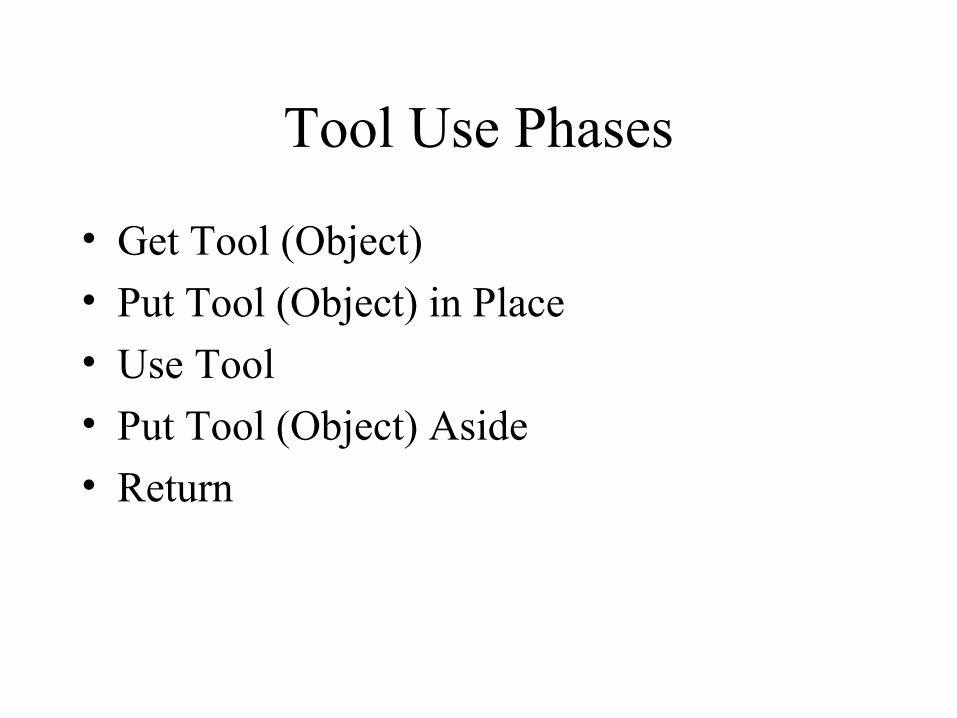
Tool Use Phases
• Get Tool (Object)
• Put Tool (Object) in Place
• Use Tool
• Put Tool (Object) Aside
• Return
The Tool Use Sequence model makes use of the “A”, “B”, “G”, and “P” parameters, which are all familiar to us, plus the new Tool
Use parameters.
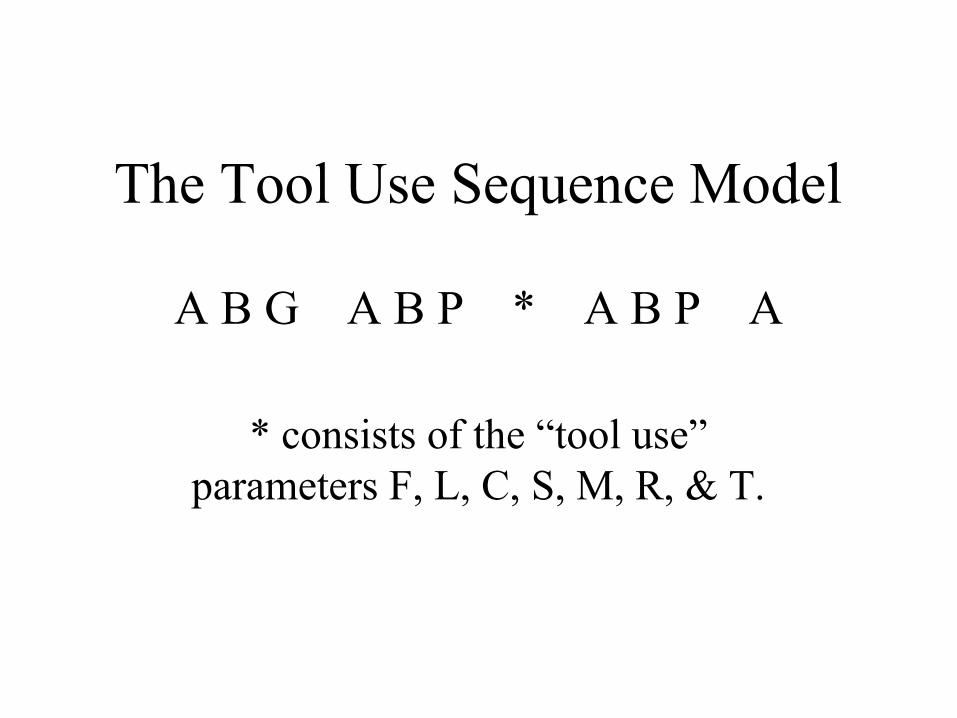
The Tool Use Sequence Model
A B G A B P * A B P A
* consists of the “tool use” parameters F, L, C, S, M, R, & T.
Tool Use Sequence Parameters
• F -- Fasten
• L -- Loosen
• C -- Cut
• S -- Surface Treat
• M -- Measure
• R -- Record
• T -- Think
Fasten / Loosen
Manually or mechanically assembling or disassembling one object to or from another using the fingers, a
hand, or hand tools.
Index values for “F” and “L” are determined by the body member
performing the action.
Finger Spins are the movement of the fingers and thumb to run a threaded fastener down or out,
and include a light application of pressure for seating / unseating
the fastener.
Wrist Actions
• Wrist Turn
• Wrist Stroke (with reposition)
• Wrist Crank
• Tap
Wrist Turn
During a wrist turn, the tool is not removed from the fastener during use and not repositioned on the fastener
after an action.
Wrist Stroke (with reposition)
In this tool use, after each stroke with the tool and before making each
subsequent stroke, the tool must be removed from the fastener and
repositioned.
Wrist Crank
Wrist crank applies to tools that are spun or rotated around a fastener
while remaining affixed to it.
Tap
This parameter covers the use of a hammer (or similar device) to exert
short tapping motions by pivoting the hand at the wrist.
Arm Actions
• Arm Turn
• Arm Stroke (with reposition)
• Arm Crank
• Strike
• T-Wrench (two hands)
Arm Turn(s)
Arm Turn(s), applying to ratchets, occur when the tool is held near the
end of the handle, resulting in a pulling action on the tool.
Arm Stroke (with reposition)
Following each stroke or pull with the tool, it must be removed and
repositioned again on the fastener before making a subsequent pull.
Arm Crank
The tool is used with a circular movement of the forearm as it is
pivoted at the elbow or the shoulder to push or crank the tool around the
fastener.
Strike
Strike is the use of a hammer with an up - and - down motion performed with the hand as it is pivoted
from the elbow.
T-Wrench (two hands)
A two - handed arm action, including the reach for each hand to the
opposite handle before making the next turn, and involving a 180 degree
turn of the T-wrench with each action.
Power Tools
The use of electric and pneumatic power wrenches to run a standard threaded fastener down or out a
length 1 1/2 times the bolt diameter.
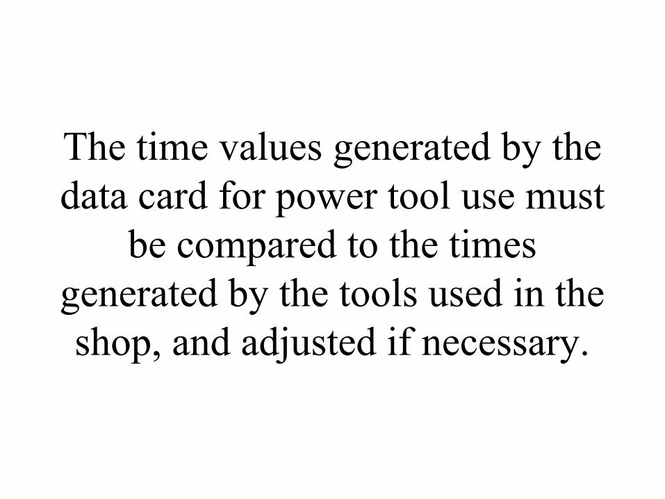
The time values generated by the data card for power tool use must
be compared to the times generated by the tools used in the shop, and adjusted if necessary.
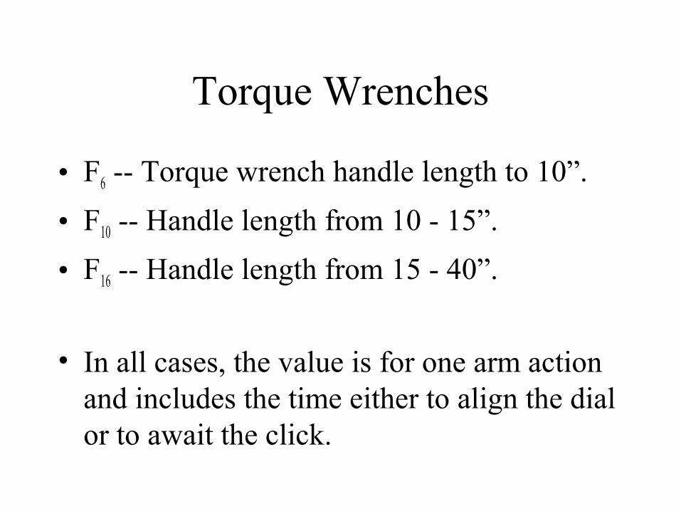
Torque Wrenches
• F6 -- Torque wrench handle length to 10”.
• F10 -- Handle length from 10 - 15”.
• F16 -- Handle length from 15 - 40”.
• In all cases, the value is for one arm action and includes the time either to align the dial or to await the click.
Tool Placement
As a general rule, the “P” parameter for the Fasten / Loosen tools will
carry the index values indicated in the Tool Placement table.
Tool Use Frequencies Example
An operator picks up a screwdriver within reach and tightens two screws with six wrist turns each and then sets
aside the screwdriver.
Multiple Tool Actions Example
A screw is fastened with a screwdriver. A total of 18 spins and
4 wrist turns are necessary.
Multiple Tool Actions Example
A nut is fastened with a ratchet wrench. Following 3 wrist cranks, 6
wrist turns are applied.
Tool Use Example -- F / L
Obtain a nut from a parts bin located within reach, place it on a bolt, and run it down with 7 finger actions.
Tool Use Example - F / L
Pick up a small screwdriver that lies within reach and fasten a screw with
6 finger actions, and set aside the tool.
Tool Use Example -- F / L
Obtain a power wrench that lies within reach, run down four 3/8”
bolts located 6” apart, and set aside wrench.
Tool Use Example -- F / L
From a position in front of an engine lathe, obtain a large T-wrench located 5 steps away and loosen one bolt on a chuck on the engine lathe with both hands using five arm actions. Set
aside the T-wrench from the machine, but within reach.
Cut
• Pliers
• Scissors
• Knife
Pliers
• C3 -- Soft: Using pliers with one hand and making one cut.
• C6 -- Medium: Using pliers with one hand and making two cuts.
• C10 -- Hard: Using the pliers with two hands and making two cuts.
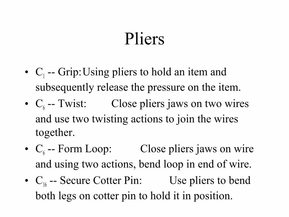
Pliers
• C1 -- Grip:Using pliers to hold an item and subsequently release the pressure on the item.
• C6 -- Twist: Close pliers jaws on two wires and use two twisting actions to join the wires together.
• C6 -- Form Loop: Close pliers jaws on wire and using two actions, bend loop in end of wire.
• C16 -- Secure Cotter Pin: Use pliers to bend both legs on cotter pin to hold it in position.
Index values using scissors are selected according to the number
of cuts used.
Tool Use Example -- Cut
An operator picks up a knife from a workbench two steps away, makes
one cut across the top of a cardboard box, and sets aside the knife on the
workbench.
Tool Use Example -- Cut
During a sewing operation, a tailor cuts the thread from the machine before setting aside the finished
garment. The scissors are held in the palm during the sewing operation.
Tool Use Example -- Cut
Following a soldering operation, an electronic component assembler must cut off the excess small - gauge wire
from a terminal connection. The pliers are located within reach.
Tool Use Example -- Cut
An electrician working on transmission lines takes a pair of
pliers from the tool belt and cuts off a piece of line. The line is heavy, such
that 2 hands are needed to cut through the wire.

Surface Treat
Surface Treat covers the activities aimed at cleaning material or particles from or applying a
substance, coating, or finish to the surface of an object.
Index values for cleaning tools are based primarily on the
amount of surface area (sq. ft.) cleaned.
Tool Use Example: Surface Treat
Before marking off a piece of sheet metal (4 ft sq) for a cutting operation,
the operator takes a rag from his or her back pocket and wipes an oily
film from the surface.
Tool Use Example: Surface Treat
Following a sanding operation, an operator standing at a workbench picks
up a brush located within reach and brushes the dust and chips from the working are (6 ft sq), and then sets aside the brush on the workbench.
Tool Use Example: Surface Treat
Before assembling three components to a casting, the operator obtains an air
hose (within reach) and blows the small metal filings left from the previous
machining operation out of 3 cavities. The distance between cavities is > 2”.
M10 -- Profile Gauge
Used to compare the profile of an object to that of the gauge.
M16 -- Fixed Scale
Covers the use of a linear (yardstick) or angular (protractor) measuring
device.
M16 -- Calipers < 12”
Covers the use of vernier calipers with a capacity to 12 inches.
M24 -- Feeler Gauge
Covers the use of a gauge to measure the gap between two points.
M32 -- Steel Tape < 6 Ft.
This parameter covers the use of a steel tape to measure, from a fixed
position, between two points.
Micrometers < 4”
• M32 -- Depth measurement
• M42 -- Outside diameter measurement
• M54 -- Inside diameter measurement
Tool Use Example -- Measure
Before welding two steel plates, a welder obtains a square and checks the angle between the plates to see
that it is correct. The square (a profile gauge) is located three steps
away on a workbench.
Tool Use Example -- Measure
Following a turning operation, a machinist checks the diameter of a small shaft with a micrometer. The
micrometer is located on and returned to the workbench 2 steps away.
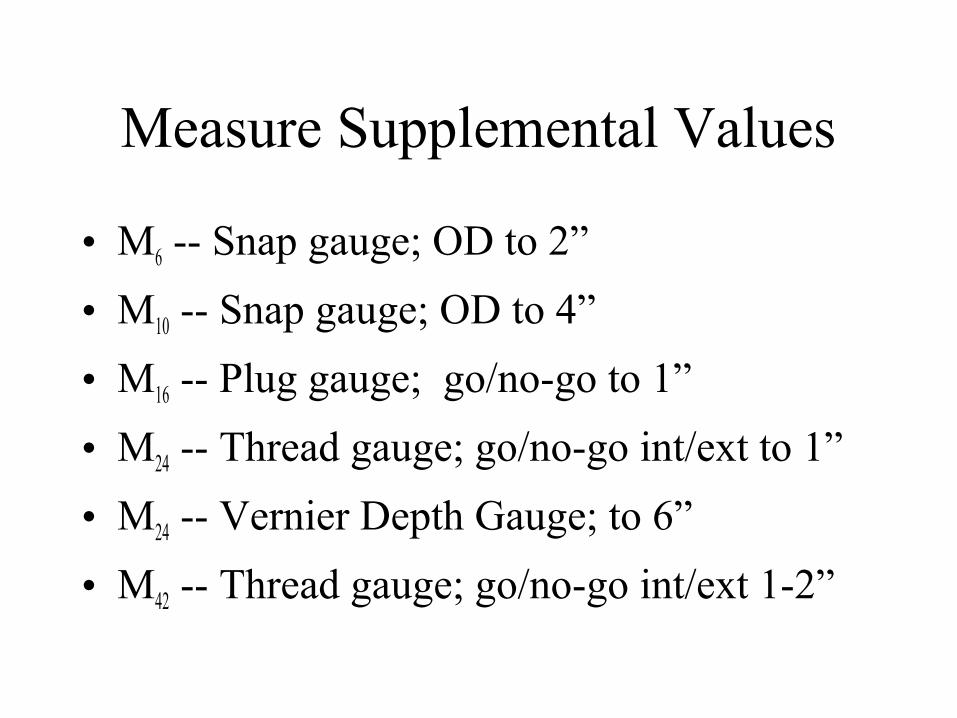
Measure Supplemental Values
• M6 -- Snap gauge; OD to 2”
• M10 -- Snap gauge; OD to 4”
• M16 -- Plug gauge; go/no-go to 1”
• M24 -- Thread gauge; go/no-go int/ext to 1”
• M24 -- Vernier Depth Gauge; to 6”
• M42 -- Thread gauge; go/no-go int/ext 1-2”
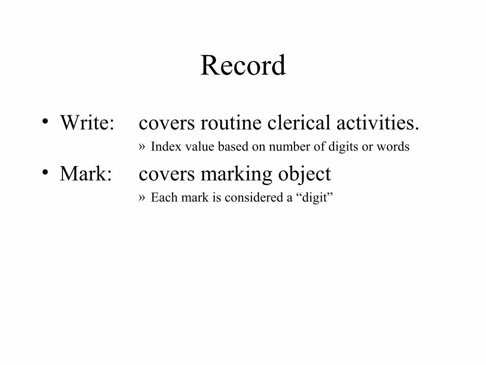
Record
• Write: covers routine clerical activities. » Index value based on number of digits or words
• Mark: covers marking object» Each mark is considered a “digit”
Tool Use Example -- Record
After finishing an assigned job, the operator picks up a clipboard and
pencil (simo) from the workbench, fills out the completion date on the
job card, and signs his name. He then returns the board and pencil to the
workbench.
Tool Use Example -- Record
To order a part, a clerk takes a pencil from her shirt pocket and writes a six-
digit part number on the requisition form on her desk. She then clips the
pencil back in her pocket.
Tool Use Example -- Record
Part of a packing operation involves identifying the components in the
carton. This involves picking up a felt marker (within reach) and marking a
6-digit number on the container.
Think
Most of the time “think” occurs internal to the manual work, but there are times it must be considered as a
separate activity.
Think -- Inspect
The type of inspection work we’re looking at here is that where only
simple “yes / no” decisions are quickly made on the existence of a
particular defect in a part.
Inspect -- Read
• The column Digits or Single Words is to be used for reading technical data (part numbers, codes, quantities, etc.)
• The column Text of Words is used when analyzing situations in which the operator reads words arranged into sentences or paragraphs.
• Other, specialized, values exist for reading gauges, scales, date/time, & tables.
Tool Use Example -- Think
During a testing operation, an electronics technician picks up a
meter lead, places it on a terminal, and reads voltage off the meter scale.
The lead is then put aside.
Tool Use Example -- Think
Prior to starting a turning operation, an operator picks up a work order set and
reads a paragraph that describes the method to be followed. It contains an
average of 30 words. The operator then places the set aside on the workbench.