Embed Size (px)
Citation preview

Prepared by
Md. Amirul Islam
Lecturer
Department of Applied Physics & Electronics
Bangabandhu Sheikh Mujibur Rahman Science &
Technology University, Gopalganj – 8100

Many historians of science believe that the compass, which uses
a magnetic needle, was used in China as early as the 13th
century B.C., its invention being of Arabic or Indian origin.
The early Greeks knew about magnetism as early as 800 B.C.
They discovered that the stone magnetite (Fe3O4) attracts pieces
of iron.
Legend ascribes the name magnetite to the shepherd Magnes,
the nails of whose shoes and the tip of whose staff stuck fast to
chunks of magnetite while he pastured his flocks.
Frenchman Pierre de Maricourt shows through experiments
that every magnet, regardless of its shape, has two poles, called
north pole and south pole.
Reference: Physics II by Robert Resnick and David Halliday, Topic – 29.0, Page – 905
The poles received their names because of the way a magnet
behaves in the presence of the Earth’s magnetic field. If a bar
magnet is suspended from its midpoint and can swing freely in a
horizontal plane, it will rotate until its north pole points to the
Earth’s geographic North Pole and its south pole points to the
Earth’s geographic South Pole.
Although the force between two magnetic poles is similar to the
force between two electric charges, there is an important
difference. Electric charges can be isolated (witness the electron
and proton), whereas a single magnetic pole has never been
isolated. That is, magnetic poles are always found in pairs.
Reference: Physics II by Robert Resnick and David Halliday, Topic – 29.0, Page – 905
The region of space surrounding any moving electric charge
contains a electric field as well as a magnetic field. Historically,
the symbol B has been used to represent a magnetic field. The
direction of B at any location is the direction in which a compass
needle points at that location.
Reference: Physics II by Robert Resnick and David Halliday, Topic – 29.1, Page – 906
We can define a magnetic field B at some point in space in terms
of the magnetic force FB that the field exerts on a test object, for
which we use a charged particle moving with a velocity v. From
experimental result we get that:
The magnitude FB of the magnetic force exerted on the particle
is proportional to the charge q and to the speed v of the particle.
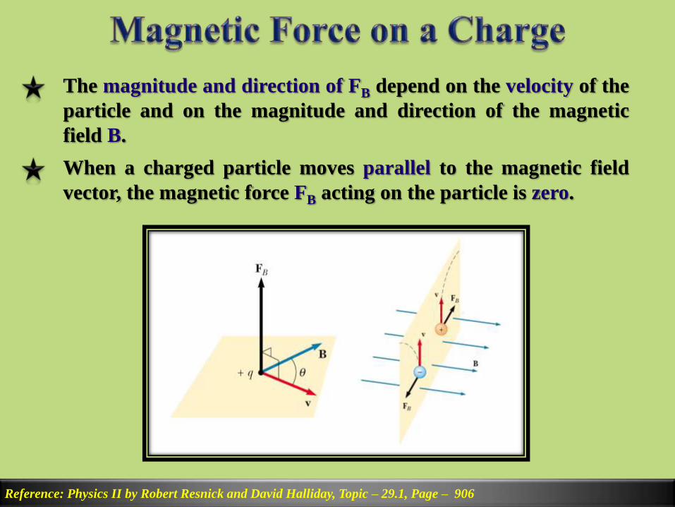
The magnitude and direction of FB depend on the velocity of the
particle and on the magnitude and direction of the magnetic
field B.
Reference: Physics II by Robert Resnick and David Halliday, Topic – 29.1, Page – 906
When a charged particle moves parallel to the magnetic field
vector, the magnetic force FB acting on the particle is zero.
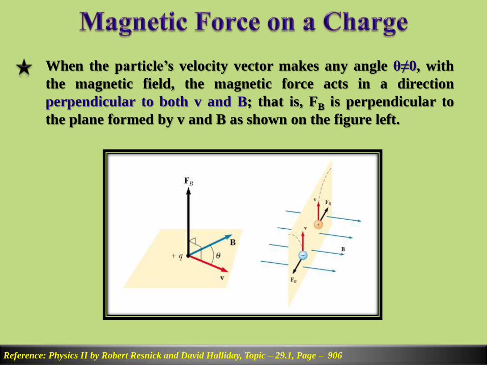
When the particle’s velocity vector makes any angle θ≠0, with
the magnetic field, the magnetic force acts in a direction
perpendicular to both v and B; that is, FB is perpendicular to
the plane formed by v and B as shown on the figure left.
Reference: Physics II by Robert Resnick and David Halliday, Topic – 29.1, Page – 906
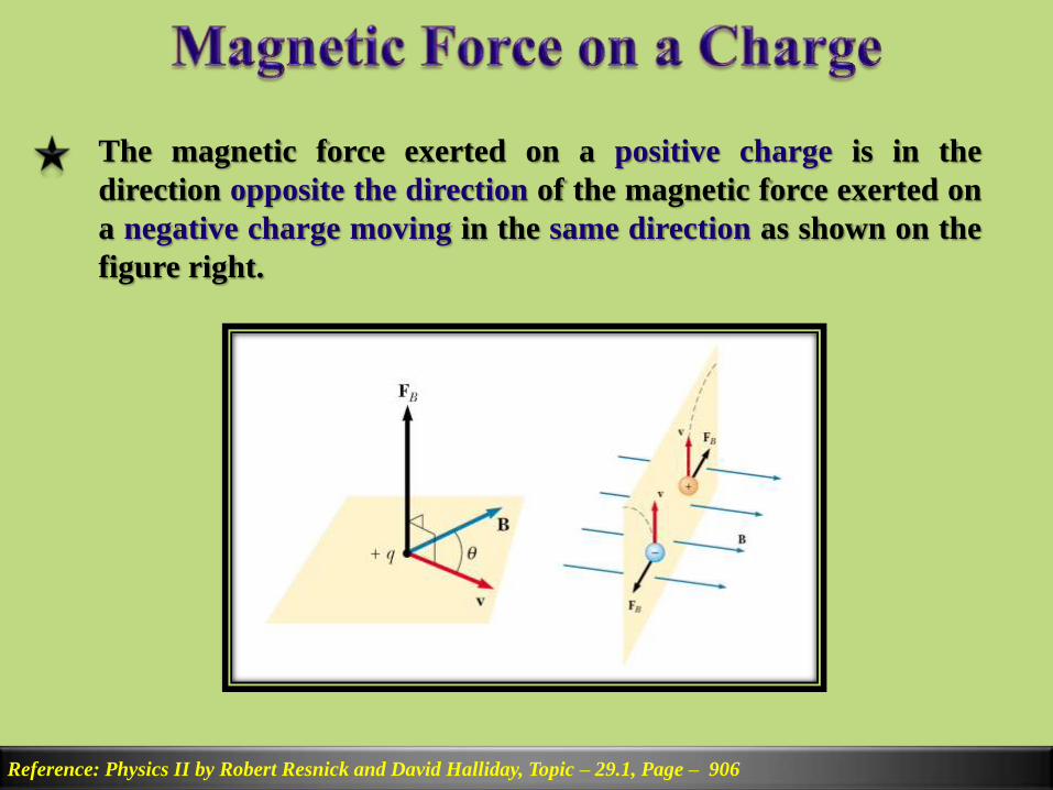
The magnetic force exerted on a positive charge is in the
direction opposite the direction of the magnetic force exerted on
a negative charge moving in the same direction as shown on the
figure right.
Reference: Physics II by Robert Resnick and David Halliday, Topic – 29.1, Page – 906
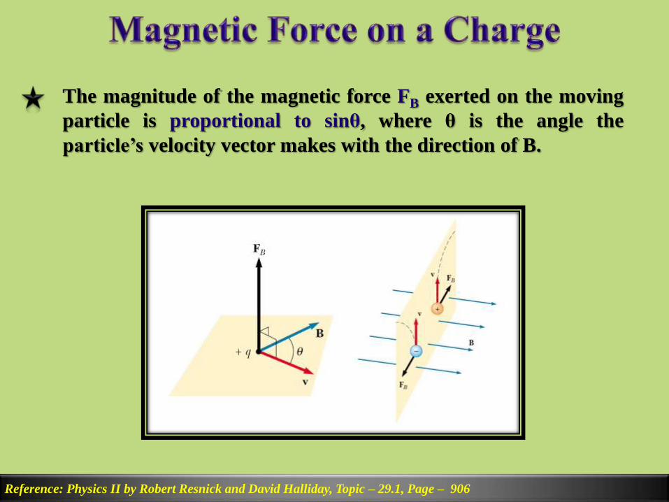
The magnitude of the magnetic force FB exerted on the moving
particle is proportional to sinθ, where θ is the angle the
particle’s velocity vector makes with the direction of B.
Reference: Physics II by Robert Resnick and David Halliday, Topic – 29.1, Page – 906
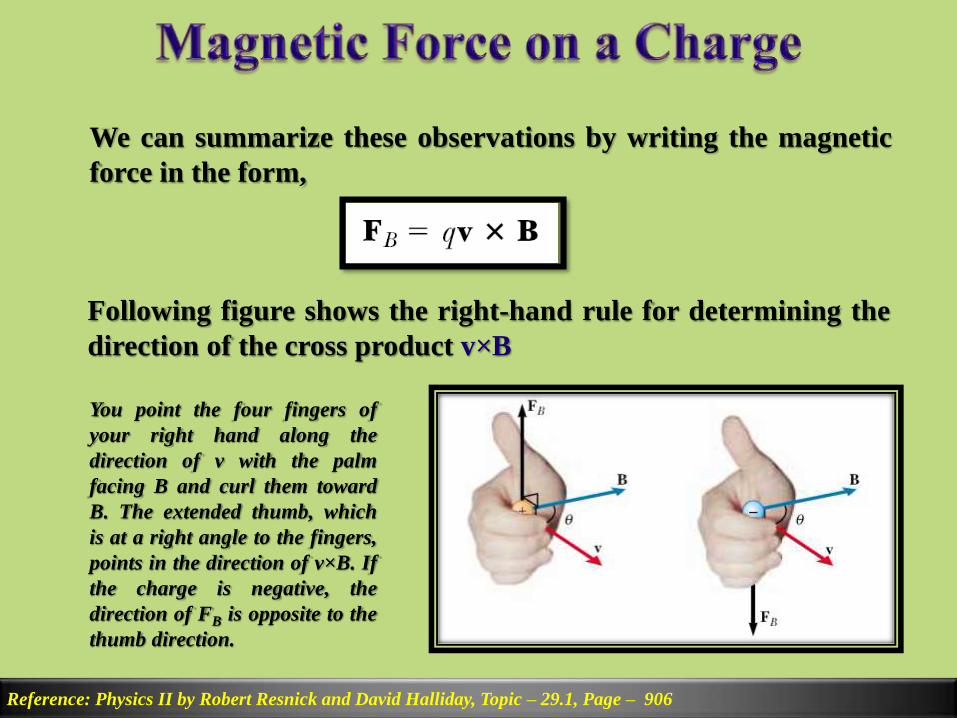
We can summarize these observations by writing the magnetic
force in the form,
Reference: Physics II by Robert Resnick and David Halliday, Topic – 29.1, Page – 906
Following figure shows the right-hand rule for determining the
direction of the cross product v×B
You point the four fingers of
your right hand along the
direction of v with the palm
facing B and curl them toward
B. The extended thumb, which
is at a right angle to the fingers,
points in the direction of v×B. If
the charge is negative, the
direction of FB is opposite to the
thumb direction.
The electric force acts in the direction of the electric field,
whereas the magnetic force acts perpendicular to the magnetic
field.
Reference: Physics II by Robert Resnick and David Halliday, Topic – 29.1, Page – 909
The electric force acts on a charged particle regardless of
whether the particle is moving, whereas the magnetic force acts
on a charged particle only when the particle is in motion.
The electric force does work in displacing a charged particle,
whereas the magnetic force associated with a steady magnetic
field does no work when a particle is displaced.

SI unit of magnetic field is the newton per coulomb-meter per
second, which is called the tesla (T):
Reference: Physics II by Robert Resnick and David Halliday, Topic – 29.1, Page – 909
Because a coulomb per second is defined to be an ampere, we
see that:
A non-SI magnetic-field unit in common use, called the gauss
(G), is related to the tesla through the conversion: 1T = 104G.
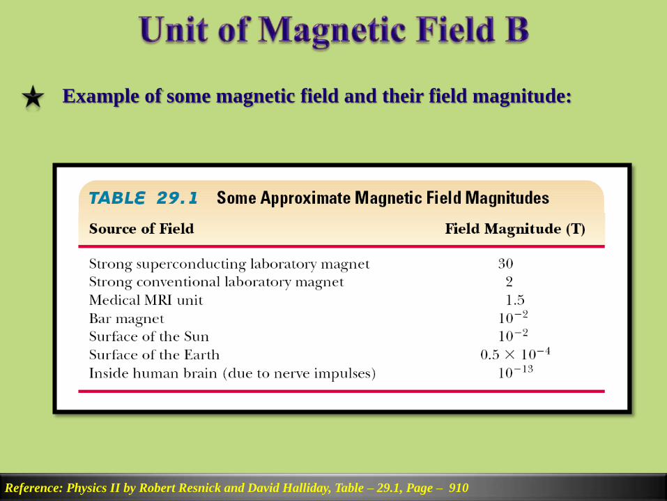
Example of some magnetic field and their field magnitude:
Reference: Physics II by Robert Resnick and David Halliday, Table – 29.1, Page – 910

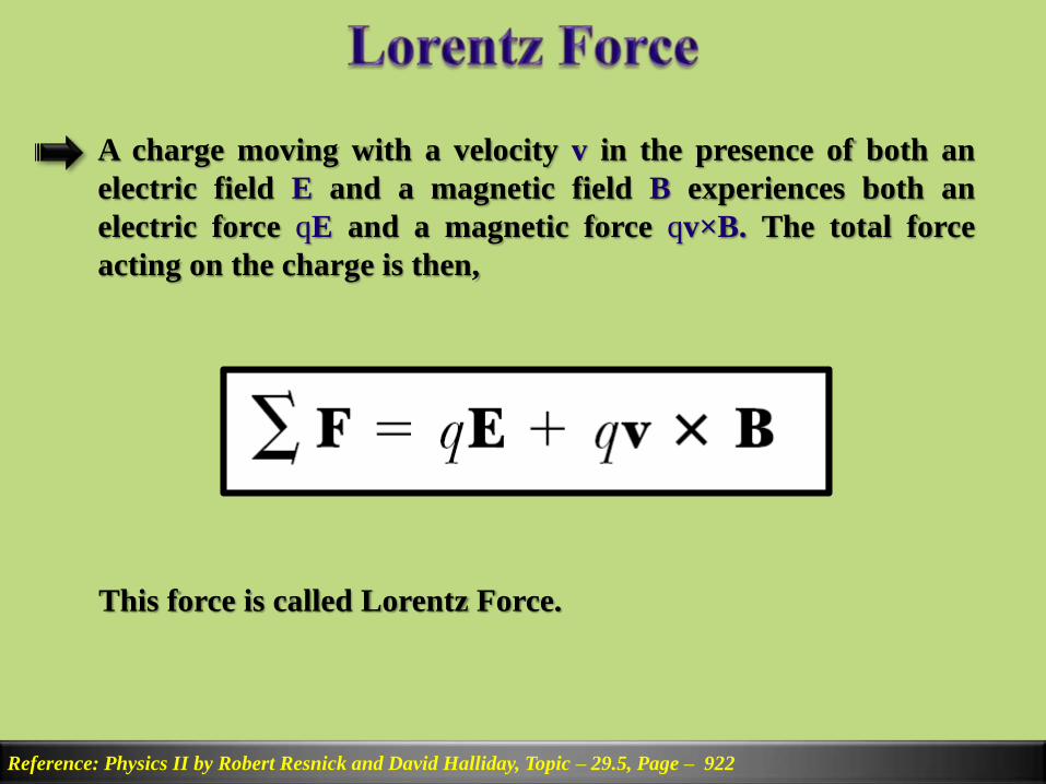
A charge moving with a velocity v in the presence of both an
electric field E and a magnetic field B experiences both an
electric force qE and a magnetic force qv×B. The total force
acting on the charge is then,
Reference: Physics II by Robert Resnick and David Halliday, Topic – 29.5, Page – 922
This force is called Lorentz Force.
Later
Reference: Later

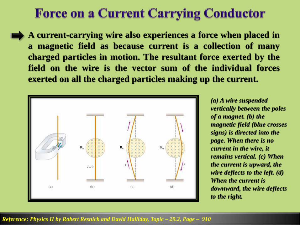
A current-carrying wire also experiences a force when placed in
a magnetic field as because current is a collection of many
charged particles in motion. The resultant force exerted by the
field on the wire is the vector sum of the individual forces
exerted on all the charged particles making up the current.
Reference: Physics II by Robert Resnick and David Halliday, Topic – 29.2, Page – 910
(a) A wire suspended
vertically between the poles
of a magnet. (b) the
magnetic field (blue crosses
signs) is directed into the
page. When there is no
current in the wire, it
remains vertical. (c) When
the current is upward, the
wire deflects to the left. (d)
When the current is
downward, the wire deflects
to the right.
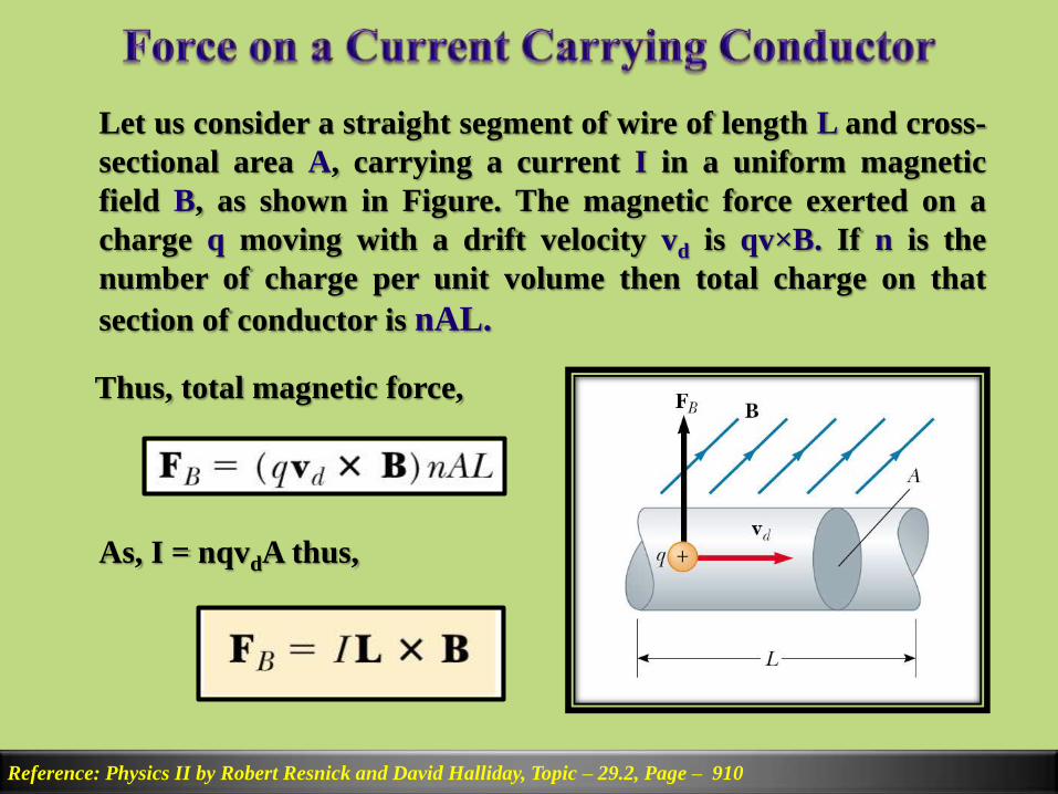
Let us consider a straight segment of wire of length L and cross-
sectional area A, carrying a current I in a uniform magnetic
field B, as shown in Figure. The magnetic force exerted on a
charge q moving with a drift velocity vd is qv×B. If n is the
number of charge per unit volume then total charge on that
section of conductor is nAL.
Reference: Physics II by Robert Resnick and David Halliday, Topic – 29.2, Page – 910
Thus, total magnetic force,
As, I = nqvdA thus,
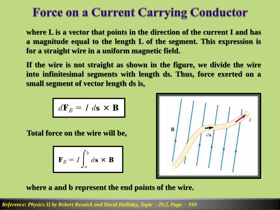
where L is a vector that points in the direction of the current I and has
a magnitude equal to the length L of the segment. This expression is
for a straight wire in a uniform magnetic field.
Reference: Physics II by Robert Resnick and David Halliday, Topic – 29.2, Page – 910
If the wire is not straight as shown in the figure, we divide the wire
into infinitesimal segments with length ds. Thus, force exerted on a
small segment of vector length ds is,
Total force on the wire will be,
where a and b represent the end points of the wire.
Later
Reference: Physics II by Robert Resnick and David Halliday, Topic – 29.3, Page – 914

Later
Reference: Physics II by Robert Resnick and David Halliday, Example – 29.5, Page – 918

Reference: Physics II by Robert Resnick and David Halliday, Topic – 30.1, Page – 938
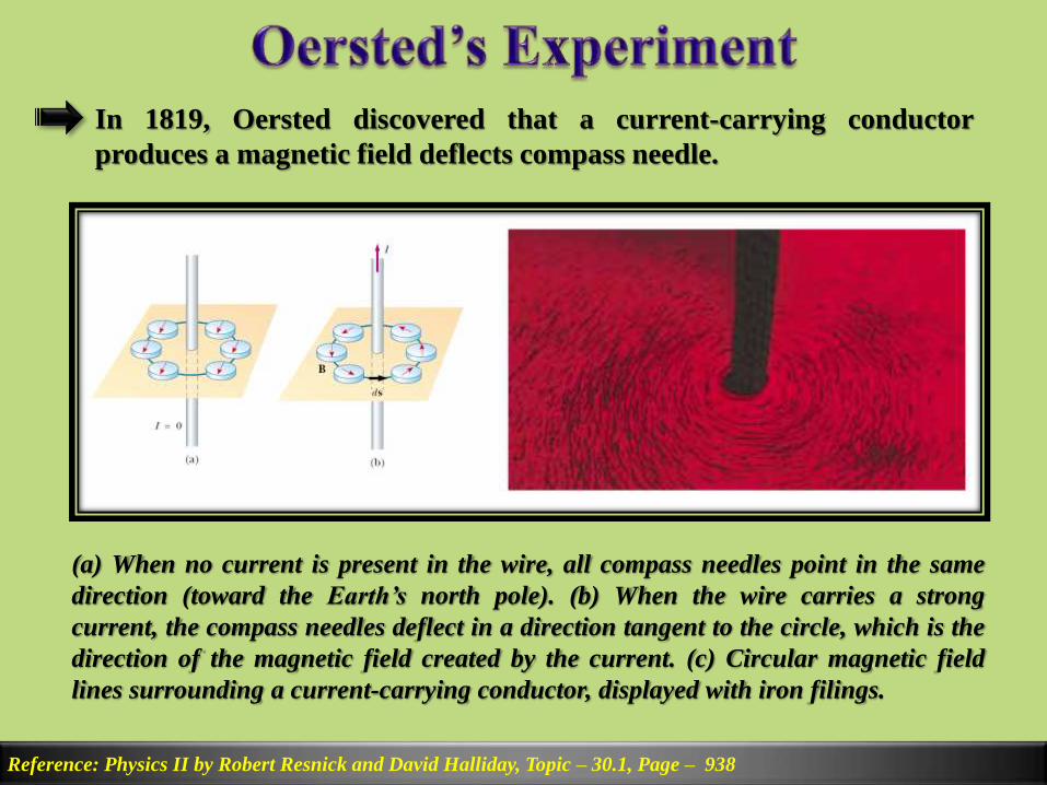
In 1819, Oersted discovered that a current-carrying conductor
produces a magnetic field deflects compass needle.
(a) When no current is present in the wire, all compass needles point in the same
direction (toward the Earth’s north pole). (b) When the wire carries a strong
current, the compass needles deflect in a direction tangent to the circle, which is the
direction of the magnetic field created by the current. (c) Circular magnetic field
lines surrounding a current-carrying conductor, displayed with iron filings.

Reference: Physics II by Robert Resnick and David Halliday, Topic – 30.1, Page – 938
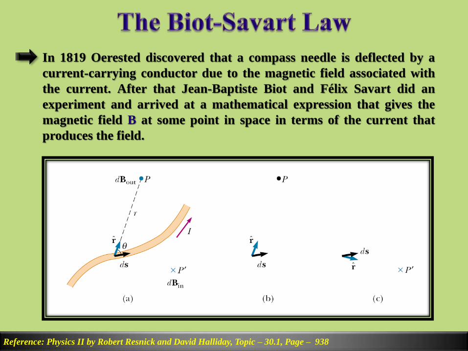
In 1819 Oerested discovered that a compass needle is deflected by a
current-carrying conductor due to the magnetic field associated with
the current. After that Jean-Baptiste Biot and Félix Savart did an
experiment and arrived at a mathematical expression that gives the
magnetic field B at some point in space in terms of the current that
produces the field.
Reference: Physics II by Robert Resnick and David Halliday, Topic – 30.1, Page – 938
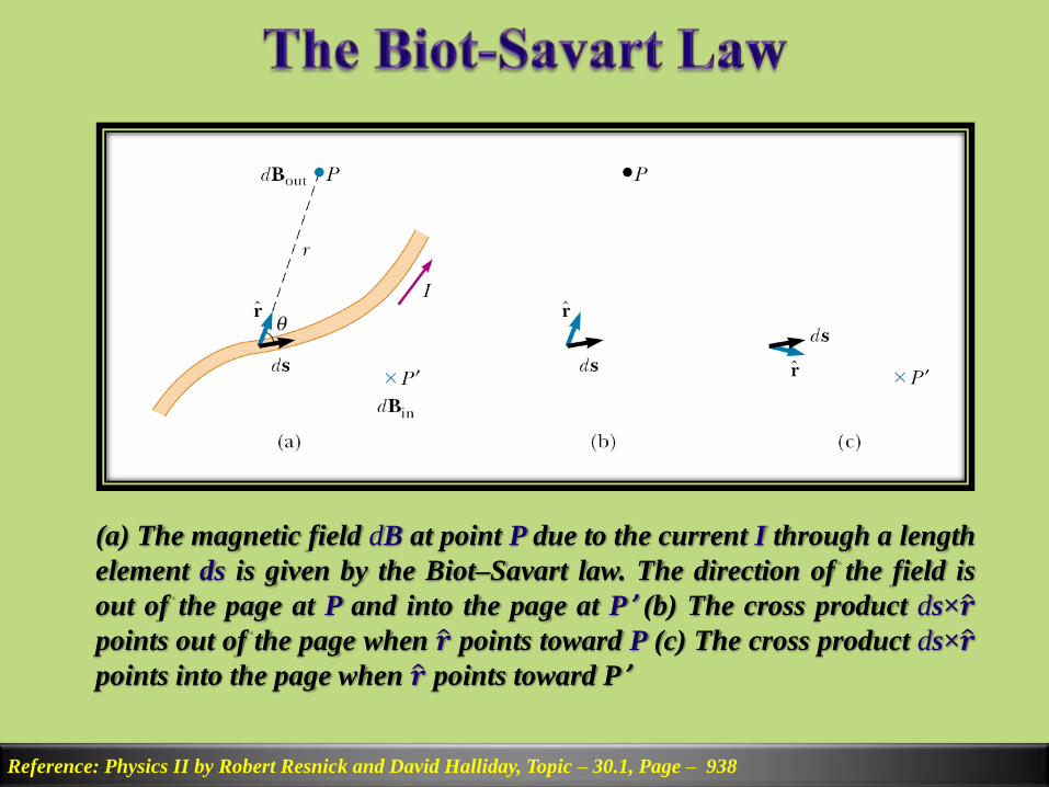
(a) The magnetic field dB at point P due to the current I through a length
element ds is given by the Biot–Savart law. The direction of the field is
out of the page at P and into the page at P’ (b) The cross product ds× 𝒓points out of the page when 𝒓 points toward P (c) The cross product ds× 𝒓points into the page when 𝒓 points toward P’
Reference: Physics II by Robert Resnick and David Halliday, Topic – 30.1, Page – 938
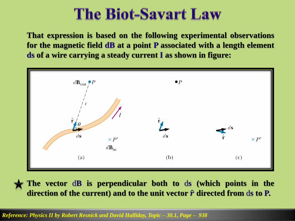
That expression is based on the following experimental observations
for the magnetic field dB at a point P associated with a length element
ds of a wire carrying a steady current I as shown in figure:
The vector dB is perpendicular both to ds (which points in the
direction of the current) and to the unit vector 𝒓 directed from ds to P.
Reference: Physics II by Robert Resnick and David Halliday, Topic – 30.1, Page – 938
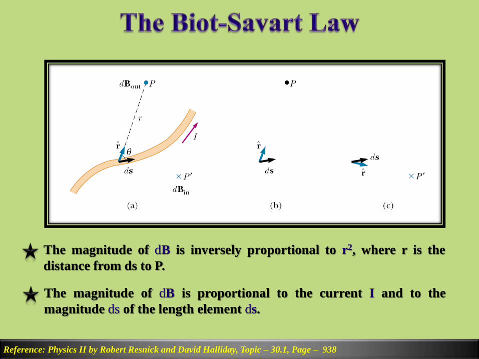
The magnitude of dB is inversely proportional to r2, where r is the
distance from ds to P.
The magnitude of dB is proportional to the current I and to the
magnitude ds of the length element ds.

Reference: Physics II by Robert Resnick and David Halliday, Topic – 30.1, Page – 938
The magnitude of dB is proportional to sinθ, where θ is the angle
between the vectors ds and 𝒓
Reference: Physics II by Robert Resnick and David Halliday, Topic – 30.1, Page – 938
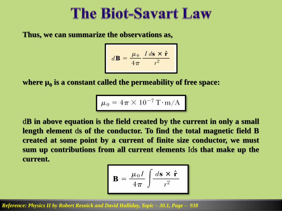
Thus, we can summarize the observations as,
where µ0 is a constant called the permeability of free space:
dB in above equation is the field created by the current in only a small
length element ds of the conductor. To find the total magnetic field B
created at some point by a current of finite size conductor, we must
sum up contributions from all current elements Ids that make up the
current.

Reference: Physics II by Robert Resnick and David Halliday, Example – 30.1, Page – 940
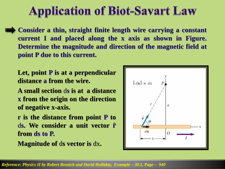
Consider a thin, straight finite length wire carrying a constant
current I and placed along the x axis as shown in Figure.
Determine the magnitude and direction of the magnetic field at
point P due to this current.
Let, point P is at a perpendicular
distance a from the wire.
A small section ds is at a distance
x from the origin on the direction
of negative x-axis.
r is the distance from point P to
ds. We consider a unit vector 𝐫from ds to P.
Magnitude of ds vector is dx.
Reference: Physics II by Robert Resnick and David Halliday, Example – 30.1, Page – 940
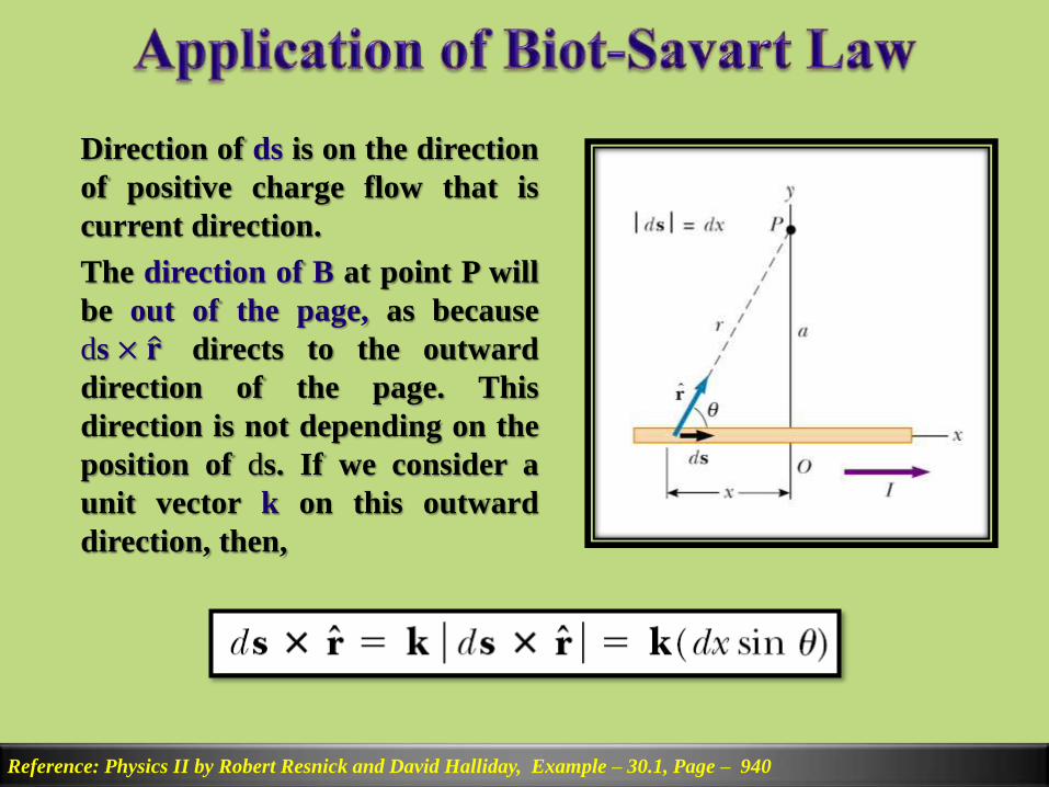
Direction of ds is on the direction
of positive charge flow that is
current direction.
The direction of B at point P will
be out of the page, as because
ds × 𝐫 directs to the outward
direction of the page. This
direction is not depending on the
position of ds. If we consider a
unit vector k on this outward
direction, then,
Reference: Physics II by Robert Resnick and David Halliday, Example – 30.1, Page – 940
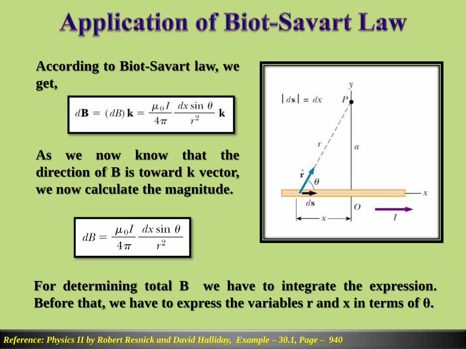
According to Biot-Savart law, we
get,
As we now know that the
direction of B is toward k vector,
we now calculate the magnitude.
For determining total B we have to integrate the expression.
Before that, we have to express the variables r and x in terms of θ.
Reference: Physics II by Robert Resnick and David Halliday, Example – 30.1, Page – 940
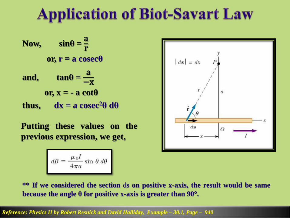
Now, sinθ =ar
or, r = a cosecθ
and, tanθ =a−x
or, x = - a cotθ
thus, dx = a cosec2θ dθ
Putting these values on the
previous expression, we get,
** If we considered the section ds on positive x-axis, the result would be same
because the angle θ for positive x-axis is greater than 90°.
Reference: Physics II by Robert Resnick and David Halliday, Example – 30.1, Page – 940
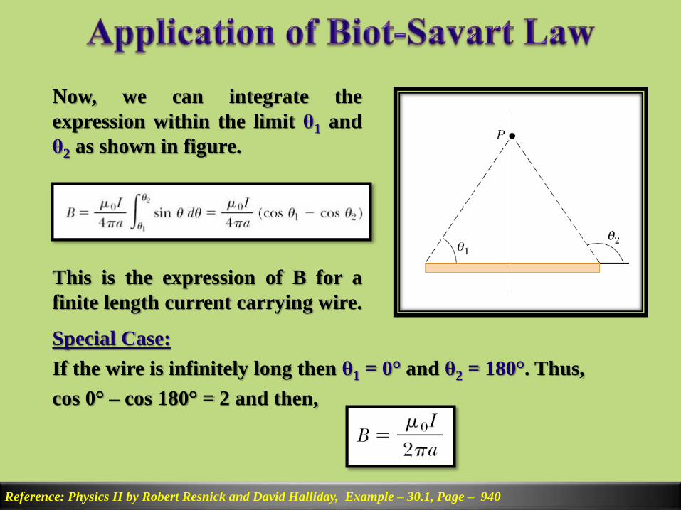
Now, we can integrate the
expression within the limit θ1 and
θ2 as shown in figure.
This is the expression of B for a
finite length current carrying wire.
Special Case:
If the wire is infinitely long then θ1 = 0° and θ2 = 180°. Thus,
cos 0° – cos 180° = 2 and then,
Reference: Physics II by Robert Resnick and David Halliday, Example – 30.2, Page – 943
Later


Reference: Physics II by Robert Resnick and David Halliday, Example – 30.1, Page – 940
The line integral of B.ds around any closed path equals µ0I.
Where I is the total continuous current passing through any
surface bounded by the closed path.
For a straight wire as shown in
figure, the field lines are circular
around the wire. If we consider
such a closed circular path with
radius r, on every point on that
path magnitude of B will be
same. If we slice that path into
infinitesimal ds sections, for
every section the angle between
ds and B will be 0°.

Reference: Physics II by Robert Resnick and David Halliday, Example – 30.1, Page – 940
Thus we get,
Here, magnitude of B is constant on that path and 𝒅𝒔 is the
circumference 2πr. This expression is calledAmpere’s Law.
** We can compare this equation with Gauss’s law, ε0 𝑬. 𝒅𝒔 = qin
Reference: Physics II by Robert Resnick and David Halliday
Later


Reference: Physics II by Robert Resnick and David Halliday
Later
Reference: Physics II by Robert Resnick and David Halliday
Later