Embed Size (px)
Citation preview
International Journal of Innovative Technology and Exploring Engineering (IJITEE) ISSN: 2278-3075, Volume-3, Issue-12, May 2014
73
Published By: Blue Eyes Intelligence Engineering & Sciences Publication Pvt. Ltd.
Abstract—Long Term Evolution (LTE) has been designed to
support only packet-switched services. It aims to provide seamless Internet Protocol (IP) connectivity between User Equipment (UE) and the packet data network (PDN), without any disruption to the end user’s applications during mobility. The term LTE “Long Term Evolution” encompasses the evolution of UMTS which is famous for high data rate because the use of OFDMA. Many of us might have heard about LTE’s peak throughput i.e. 300Mbps, but how many of us know how we calculate that? This paper provides the information, how this number is calculated? And assumptions behind? In this paper, authors have explained the calculations of theoretical throughput for both the LTE FDD and TDD systems.
Index Terms—LTE, Throughput, Frequency Division
Duplexing, Time Division Duplexing.
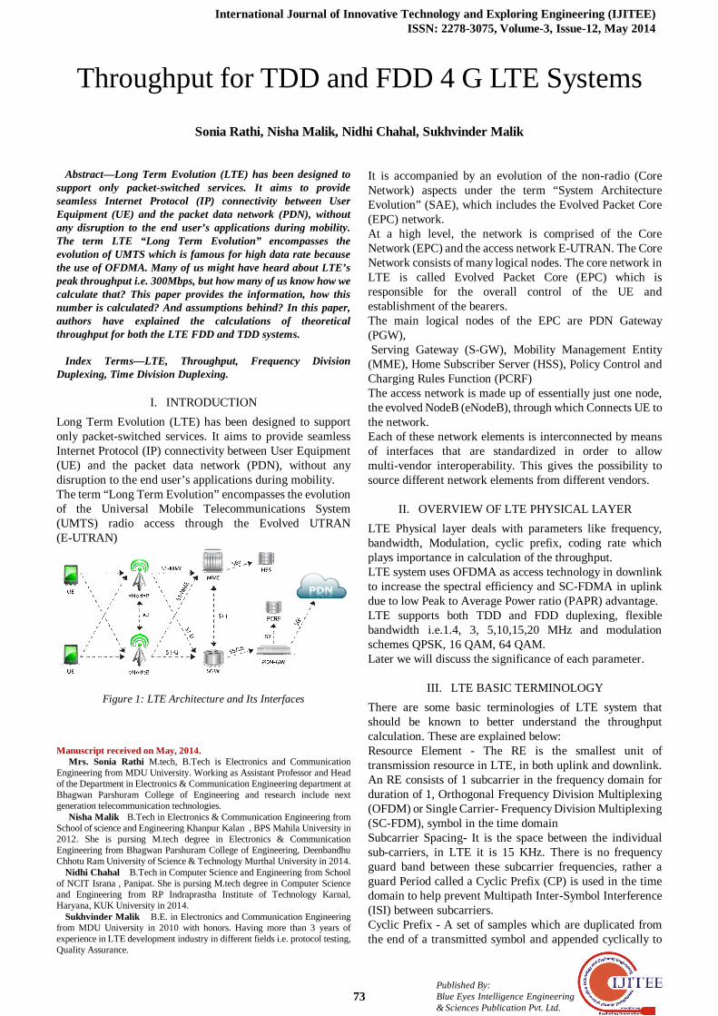
I. INTRODUCTION Long Term Evolution (LTE) has been designed to support only packet-switched services. It aims to provide seamless Internet Protocol (IP) connectivity between User Equipment (UE) and the packet data network (PDN), without any disruption to the end user’s applications during mobility. The term “Long Term Evolution” encompasses the evolution of the Universal Mobile Telecommunications System (UMTS) radio access through the Evolved UTRAN (E-UTRAN)
Figure 1: LTE Architecture and Its Interfaces
Manuscript received on May, 2014.
Mrs. Sonia Rathi M.tech, B.Tech is Electronics and Communication Engineering from MDU University. Working as Assistant Professor and Head of the Department in Electronics & Communication Engineering department at Bhagwan Parshuram College of Engineering and research include next generation telecommunication technologies.
Nisha Malik B.Tech in Electronics & Communication Engineering from School of science and Engineering Khanpur Kalan , BPS Mahila University in 2012. She is pursing M.tech degree in Electronics & Communication Engineering from Bhagwan Parshuram College of Engineering, Deenbandhu Chhotu Ram University of Science & Technology Murthal University in 2014.
Nidhi Chahal B.Tech in Computer Science and Engineering from School of NCIT Israna , Panipat. She is pursing M.tech degree in Computer Science and Engineering from RP Indraprastha Institute of Technology Karnal, Haryana, KUK University in 2014.
Sukhvinder Malik B.E. in Electronics and Communication Engineering from MDU University in 2010 with honors. Having more than 3 years of experience in LTE development industry in different fields i.e. protocol testing, Quality Assurance.
It is accompanied by an evolution of the non-radio (Core Network) aspects under the term “System Architecture Evolution” (SAE), which includes the Evolved Packet Core (EPC) network. At a high level, the network is comprised of the Core Network (EPC) and the access network E-UTRAN. The Core Network consists of many logical nodes. The core network in LTE is called Evolved Packet Core (EPC) which is responsible for the overall control of the UE and establishment of the bearers. The main logical nodes of the EPC are PDN Gateway (PGW), Serving Gateway (S-GW), Mobility Management Entity (MME), Home Subscriber Server (HSS), Policy Control and Charging Rules Function (PCRF) The access network is made up of essentially just one node, the evolved NodeB (eNodeB), through which Connects UE to the network. Each of these network elements is interconnected by means of interfaces that are standardized in order to allow multi-vendor interoperability. This gives the possibility to source different network elements from different vendors.
II. OVERVIEW OF LTE PHYSICAL LAYER LTE Physical layer deals with parameters like frequency, bandwidth, Modulation, cyclic prefix, coding rate which plays importance in calculation of the throughput. LTE system uses OFDMA as access technology in downlink to increase the spectral efficiency and SC-FDMA in uplink due to low Peak to Average Power ratio (PAPR) advantage. LTE supports both TDD and FDD duplexing, flexible bandwidth i.e.1.4, 3, 5,10,15,20 MHz and modulation schemes QPSK, 16 QAM, 64 QAM. Later we will discuss the significance of each parameter.
III. LTE BASIC TERMINOLOGY There are some basic terminologies of LTE system that should be known to better understand the throughput calculation. These are explained below: Resource Element - The RE is the smallest unit of transmission resource in LTE, in both uplink and downlink. An RE consists of 1 subcarrier in the frequency domain for duration of 1, Orthogonal Frequency Division Multiplexing (OFDM) or Single Carrier- Frequency Division Multiplexing (SC-FDM), symbol in the time domain Subcarrier Spacing- It is the space between the individual sub-carriers, in LTE it is 15 KHz. There is no frequency guard band between these subcarrier frequencies, rather a guard Period called a Cyclic Prefix (CP) is used in the time domain to help prevent Multipath Inter-Symbol Interference (ISI) between subcarriers. Cyclic Prefix - A set of samples which are duplicated from the end of a transmitted symbol and appended cyclically to
Throughput for TDD and FDD 4 G LTE Systems
Sonia Rathi, Nisha Malik, Nidhi Chahal, Sukhvinder Malik
Throughput for TDD and FDD 4 G LTE Systems
74 Published By: Blue Eyes Intelligence Engineering & Sciences Publication Pvt. Ltd.
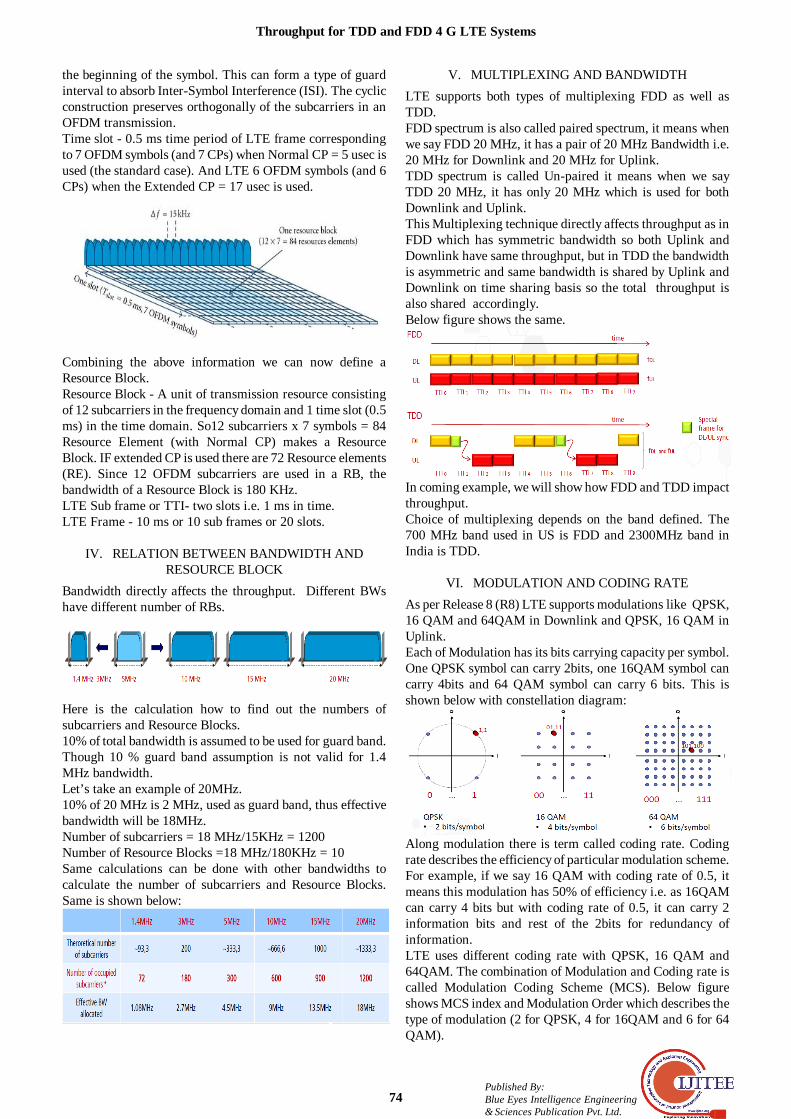
the beginning of the symbol. This can form a type of guard interval to absorb Inter-Symbol Interference (ISI). The cyclic construction preserves orthogonally of the subcarriers in an OFDM transmission. Time slot - 0.5 ms time period of LTE frame corresponding to 7 OFDM symbols (and 7 CPs) when Normal CP = 5 usec is used (the standard case). And LTE 6 OFDM symbols (and 6 CPs) when the Extended CP = 17 usec is used.
Combining the above information we can now define a Resource Block. Resource Block - A unit of transmission resource consisting of 12 subcarriers in the frequency domain and 1 time slot (0.5 ms) in the time domain. So12 subcarriers x 7 symbols = 84 Resource Element (with Normal CP) makes a Resource Block. IF extended CP is used there are 72 Resource elements (RE). Since 12 OFDM subcarriers are used in a RB, the bandwidth of a Resource Block is 180 KHz. LTE Sub frame or TTI- two slots i.e. 1 ms in time. LTE Frame - 10 ms or 10 sub frames or 20 slots.
IV. RELATION BETWEEN BANDWIDTH AND RESOURCE BLOCK
Bandwidth directly affects the throughput. Different BWs have different number of RBs.
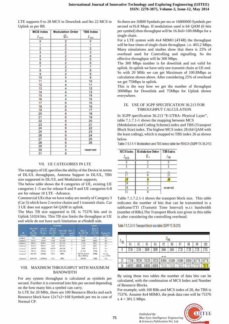
Here is the calculation how to find out the numbers of subcarriers and Resource Blocks. 10% of total bandwidth is assumed to be used for guard band. Though 10 % guard band assumption is not valid for 1.4 MHz bandwidth. Let’s take an example of 20MHz. 10% of 20 MHz is 2 MHz, used as guard band, thus effective bandwidth will be 18MHz. Number of subcarriers = 18 MHz/15KHz = 1200 Number of Resource Blocks =18 MHz/180KHz = 10 Same calculations can be done with other bandwidths to calculate the number of subcarriers and Resource Blocks. Same is shown below:
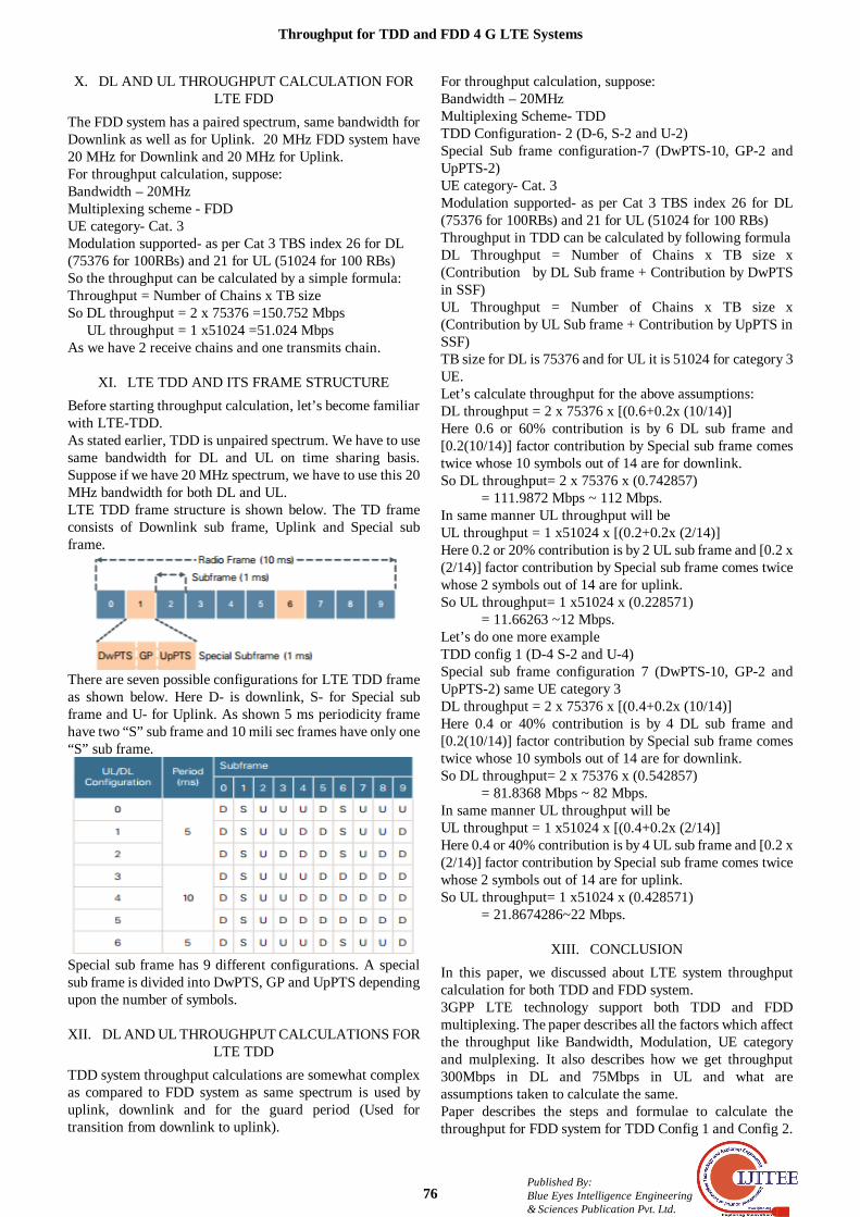
V. MULTIPLEXING AND BANDWIDTH LTE supports both types of multiplexing FDD as well as TDD. FDD spectrum is also called paired spectrum, it means when we say FDD 20 MHz, it has a pair of 20 MHz Bandwidth i.e. 20 MHz for Downlink and 20 MHz for Uplink. TDD spectrum is called Un-paired it means when we say TDD 20 MHz, it has only 20 MHz which is used for both Downlink and Uplink. This Multiplexing technique directly affects throughput as in FDD which has symmetric bandwidth so both Uplink and Downlink have same throughput, but in TDD the bandwidth is asymmetric and same bandwidth is shared by Uplink and Downlink on time sharing basis so the total throughput is also shared accordingly. Below figure shows the same.
In coming example, we will show how FDD and TDD impact throughput. Choice of multiplexing depends on the band defined. The 700 MHz band used in US is FDD and 2300MHz band in India is TDD.
VI. MODULATION AND CODING RATE As per Release 8 (R8) LTE supports modulations like QPSK, 16 QAM and 64QAM in Downlink and QPSK, 16 QAM in Uplink. Each of Modulation has its bits carrying capacity per symbol. One QPSK symbol can carry 2bits, one 16QAM symbol can carry 4bits and 64 QAM symbol can carry 6 bits. This is shown below with constellation diagram:
Along modulation there is term called coding rate. Coding rate describes the efficiency of particular modulation scheme. For example, if we say 16 QAM with coding rate of 0.5, it means this modulation has 50% of efficiency i.e. as 16QAM can carry 4 bits but with coding rate of 0.5, it can carry 2 information bits and rest of the 2bits for redundancy of information. LTE uses different coding rate with QPSK, 16 QAM and 64QAM. The combination of Modulation and Coding rate is called Modulation Coding Scheme (MCS). Below figure shows MCS index and Modulation Order which describes the type of modulation (2 for QPSK, 4 for 16QAM and 6 for 64 QAM).
International Journal of Innovative Technology and Exploring Engineering (IJITEE) ISSN: 2278-3075, Volume-3, Issue-12, May 2014
75
Published By: Blue Eyes Intelligence Engineering & Sciences Publication Pvt. Ltd.
LTE supports 0 to 28 MCS in Downlink and 0to 22 MCS in Uplink as per R8.
VII. UE CATEGORIES IN LTE The category of UE specifies the ability of the Device in terms of DL/UL throughputs, Antenna Support in DL/UL, TBS size supported in DL/UL and Modulation supports. The below table shows the 8 categories of UE, existing UE categories 1 -5 are for release 8 and 9 and UE categories 6-8 are for release 10 LTE –Advance. Commercial UEs that we have today are mostly of Category 3 (Cat 3) which have 2 receive chains and 1 transmit chain. Cat 3 UE does not support 64 QAM in uplink. The Max TB size supported in DL is 75376 bits and in Uplink 51024 bits. This TB size limits the throughput at UE end while do not have such limitation at eNodeB side.
VIII. MAXIMUM THROUGHPUT WITH MAXIMUM BANDWIDTH
For any system throughput is calculated as symbols per second. Further it is converted into bits per second depending on the how many bits a symbol can carry. In LTE for 20 MHz, there are 100 Resource Blocks and each Resource block have 12x7x2=168 Symbols per ms in case of Normal CP.
So there are 16800 Symbols per ms or 16800000 Symbols per second or16.8 Msps. If modulation used is 64 QAM (6 bits per symbol) then throughput will be 16.8x6=100.8Mbps for a single chain. For a LTE system with 4x4 MIMO (4T4R) the throughput will be four times of single chain throughput. i.e. 403.2 Mbps. Many simulations and studies show that there is 25% of overhead used for Controlling and signalling. So the effective throughput will be 300 Mbps. The 300 Mbps number is for downlink and not valid for uplink. In uplink we have only one transmit chain at UE end. So with 20 MHz we can get Maximum of 100.8Mbps as calculation shown above. After considering 25% of overhead we get 75Mbps in uplink. This is the way how we get the number of throughput 300Mbps for Downlink and 75Mbps for Uplink shown everywhere.
IX. USE OF 3GPP SPECIFICATION 36.213 FOR THROUGHPUT CALCULATION
In 3GPP specification 36.213 “E-UTRA- Physical Layer”, table 7.1.7.1-1 shows the mapping between MCS (Modulation and Coding Scheme) index and TBS (Transport Block Size) index. The highest MCS index 28 (64 QAM with the least coding), which is mapped to TBS index 26 as shown below.
Table 7.1.7.2.1-1 shows the transport block size. This table indicates the number of bits that can be transmitted in a subframe/TTI (Transmit Time Interval) w.r.t bandwidth (number of RBs).The Transport Block size given in this table is after considering the controlling overhead.
By using these two tables the number of data bits can be calculated, with the combination of MCS Index and Number of Resource Blocks. For example, with 100 RBs and MCS index of 28, the TBS is 75376. Assume 4x4 MIMO, the peak data rate will be 75376 x 4 = 301.5 Mbps.
Throughput for TDD and FDD 4 G LTE Systems
76 Published By: Blue Eyes Intelligence Engineering & Sciences Publication Pvt. Ltd.
X. DL AND UL THROUGHPUT CALCULATION FOR LTE FDD
The FDD system has a paired spectrum, same bandwidth for Downlink as well as for Uplink. 20 MHz FDD system have 20 MHz for Downlink and 20 MHz for Uplink. For throughput calculation, suppose: Bandwidth – 20MHz Multiplexing scheme - FDD UE category- Cat. 3 Modulation supported- as per Cat 3 TBS index 26 for DL (75376 for 100RBs) and 21 for UL (51024 for 100 RBs) So the throughput can be calculated by a simple formula: Throughput = Number of Chains x TB size So DL throughput = 2 x 75376 =150.752 Mbps UL throughput = 1 x51024 =51.024 Mbps As we have 2 receive chains and one transmits chain.
XI. LTE TDD AND ITS FRAME STRUCTURE Before starting throughput calculation, let’s become familiar with LTE-TDD. As stated earlier, TDD is unpaired spectrum. We have to use same bandwidth for DL and UL on time sharing basis. Suppose if we have 20 MHz spectrum, we have to use this 20 MHz bandwidth for both DL and UL. LTE TDD frame structure is shown below. The TD frame consists of Downlink sub frame, Uplink and Special sub frame.
There are seven possible configurations for LTE TDD frame as shown below. Here D- is downlink, S- for Special sub frame and U- for Uplink. As shown 5 ms periodicity frame have two “S” sub frame and 10 mili sec frames have only one “S” sub frame.
Special sub frame has 9 different configurations. A special sub frame is divided into DwPTS, GP and UpPTS depending upon the number of symbols.
XII. DL AND UL THROUGHPUT CALCULATIONS FOR LTE TDD
TDD system throughput calculations are somewhat complex as compared to FDD system as same spectrum is used by uplink, downlink and for the guard period (Used for transition from downlink to uplink).
For throughput calculation, suppose: Bandwidth – 20MHz Multiplexing Scheme- TDD TDD Configuration- 2 (D-6, S-2 and U-2) Special Sub frame configuration-7 (DwPTS-10, GP-2 and UpPTS-2) UE category- Cat. 3 Modulation supported- as per Cat 3 TBS index 26 for DL (75376 for 100RBs) and 21 for UL (51024 for 100 RBs) Throughput in TDD can be calculated by following formula DL Throughput = Number of Chains x TB size x (Contribution by DL Sub frame + Contribution by DwPTS in SSF) UL Throughput = Number of Chains x TB size x (Contribution by UL Sub frame + Contribution by UpPTS in SSF) TB size for DL is 75376 and for UL it is 51024 for category 3 UE. Let’s calculate throughput for the above assumptions: DL throughput = 2 x 75376 x [(0.6+0.2x (10/14)] Here 0.6 or 60% contribution is by 6 DL sub frame and [0.2(10/14)] factor contribution by Special sub frame comes twice whose 10 symbols out of 14 are for downlink. So DL throughput= 2 x 75376 x (0.742857) = 111.9872 Mbps ~ 112 Mbps. In same manner UL throughput will be UL throughput = 1 x51024 x [(0.2+0.2x (2/14)] Here 0.2 or 20% contribution is by 2 UL sub frame and [0.2 x (2/14)] factor contribution by Special sub frame comes twice whose 2 symbols out of 14 are for uplink. So UL throughput= 1 x51024 x (0.228571) = 11.66263 ~12 Mbps. Let’s do one more example TDD config 1 (D-4 S-2 and U-4) Special sub frame configuration 7 (DwPTS-10, GP-2 and UpPTS-2) same UE category 3 DL throughput = 2 x 75376 x [(0.4+0.2x (10/14)] Here 0.4 or 40% contribution is by 4 DL sub frame and [0.2(10/14)] factor contribution by Special sub frame comes twice whose 10 symbols out of 14 are for downlink. So DL throughput= 2 x 75376 x (0.542857) = 81.8368 Mbps ~ 82 Mbps. In same manner UL throughput will be UL throughput = 1 x51024 x [(0.4+0.2x (2/14)] Here 0.4 or 40% contribution is by 4 UL sub frame and [0.2 x (2/14)] factor contribution by Special sub frame comes twice whose 2 symbols out of 14 are for uplink. So UL throughput= 1 x51024 x (0.428571) = 21.8674286~22 Mbps.
XIII. CONCLUSION In this paper, we discussed about LTE system throughput calculation for both TDD and FDD system. 3GPP LTE technology support both TDD and FDD multiplexing. The paper describes all the factors which affect the throughput like Bandwidth, Modulation, UE category and mulplexing. It also describes how we get throughput 300Mbps in DL and 75Mbps in UL and what are assumptions taken to calculate the same. Paper describes the steps and formulae to calculate the throughput for FDD system for TDD Config 1 and Config 2.
International Journal of Innovative Technology and Exploring Engineering (IJITEE) ISSN: 2278-3075, Volume-3, Issue-12, May 2014
77
Published By: Blue Eyes Intelligence Engineering & Sciences Publication Pvt. Ltd.
The throughput calculations shown in this paper is theoretical and limited by the assumptions taken to calculate for calculation.
REFERENCES [1] Lte - The Umts Long Term Evolution from Theory To Practice 2nd
Edition by Stefania Sesia , Issam Toufik, Matthew Baker [2] 3GPP TS 36.213 “Evolved Universal Terrestrial Radio Access
(E-UTRA) Physical layer procedures”. [3] 3GPP TS 36.221 “Evolved Universal Terrestrial Radio Access
(E-UTRA); Medium Access Control (MAC) protocol specification” [4] 3GPP TS 36.300 “Evolved Universal Terrestrial Radio Access
(E-UTRA), Evolved Universal Terrestrial Radio Access Network (E-UTRAN).
[5] 3GPP TS 24.302: “Access to the 3GPP Evolved Packet Core (EPC) via Non-3GPP Access Networks”.
[6] 3GPP TS 36.331: “Evolved Universal Terrestrial Radio Access (E-UTRAN); Radio Resource Control (RRC) Protocol Specification”
[7] 3GPP TS 36.401: “Evolved Universal Terrestrial Radio Access Network (E-UTRAN); Architecture Description”
[8] 3GPP TS 36.413: “Evolved Universal Terrestrial Radio Access Network (E-UTRAN); S1 Application Protocol (S1AP).
Mrs. Sonia Rathi M.tech, B.Tech is Electronics and Communication Engineering from MDU University. Working as Assistant Professor and Head of the Department in Electronics & Communication Engineering department at Bhagwan Parshuram College of Engineering and research include next generation telecommunication technologies.
Nisha Malik B.Tech in Electronics & Communication Engineering from School of science and Engineering Khanpur Kalan , BPS Mahila University in 2012. She is pursing M.tech degree in Electronics & Communication Engineering from Bhagwan Parshuram College of Engineering,Deenbandhu Chhotu Ram University of Science & Technology Murthal University in 2014.
Nidhi Chahal B.Tech in Computer Science and Engineering from School of NCIT Israna , Panipat. She is pursing M.tech degree in Computer Science and Engineering from RP Indraprastha Institute of Technology Karnal, Haryana, KUK University in 2014. .
Sukhvinder Singh Malik B.E. in Electronics and Communication Engineering from MDU University in 2010 with honors. Having more than 3 years of experience in LTE development industry in different fields i.e. protocol testing,


![[PPT]PowerPoint Presentationweb.cs.wpi.edu/~claypool/papers/4g-lte/slides.pptx · Web viewGeneral Problem Statement LTE responds to poor signal quality by decreasing throughput LTE](https://img.dokumen.tips/doc/110x75/5b99bac009d3f2dc2b8c4ea3/pptpowerpoint-claypoolpapers4g-lteslidespptx-web-viewgeneral-problem-statement.jpg)


![An Experimental Evaluation of LTE-A Throughput for Drones...Paper Contribution Release Height TrafficThroughput UL Throughput DL Albaladejo et al. [3] Derived a model for throughput](https://img.dokumen.tips/doc/110x75/60d57bafed3211582b334085/an-experimental-evaluation-of-lte-a-throughput-for-drones-paper-contribution.jpg)


![Energy Efficient and Fair Resource Allocation for LTE ... · maximize LTE-U throughput while guaranteeing the Wi-Fi throughput threshold [18]. In [19], power allocation problem of](https://img.dokumen.tips/doc/110x75/6018c85944d0845fb339ebc1/energy-eficient-and-fair-resource-allocation-for-lte-maximize-lte-u-throughput.jpg)