Embed Size (px)
Citation preview

COMPUTER ORGANIZATION AND ASSEMBLY LANGUAGE
Lecture 15
Single Cycle - Abstract View
Abstract View elements that operate on data values (combinational) elements that contain state (sequential)
Implementation Design the datapath Design the control
Address Instruction
InstructionMemory
Write Data
Reg Addr
Reg Addr
Reg Addr
Register
File ALU
DataMemory
Address
Write Data
Read DataPC
Read Data
Read Data
26
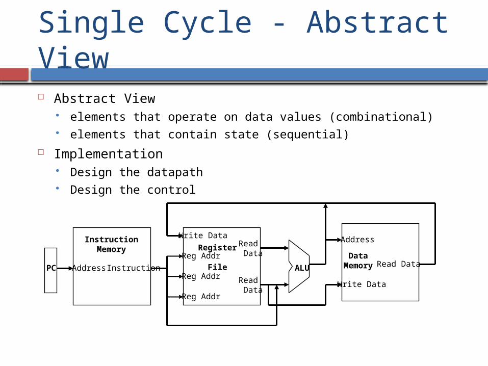
Single cycle Datapath
Write Data
Read Addr 1
Read Addr 2
Write Addr
Register
File
Read Data 1
Read Data 2
ALU
ovfzero
ALU controlRegWrite
DataMemory
Address
Write Data
Read Data
MemWrite
MemReadSign
Extend16 32
MemtoRegALUSrc
ReadAddress
Instruction
InstructionMemory
Add
PC
4 Shiftleft 2
Add
PCSrc
0
1Shiftleft 2
Jump
28PC+4[31-28]
32
Instr[25-0]
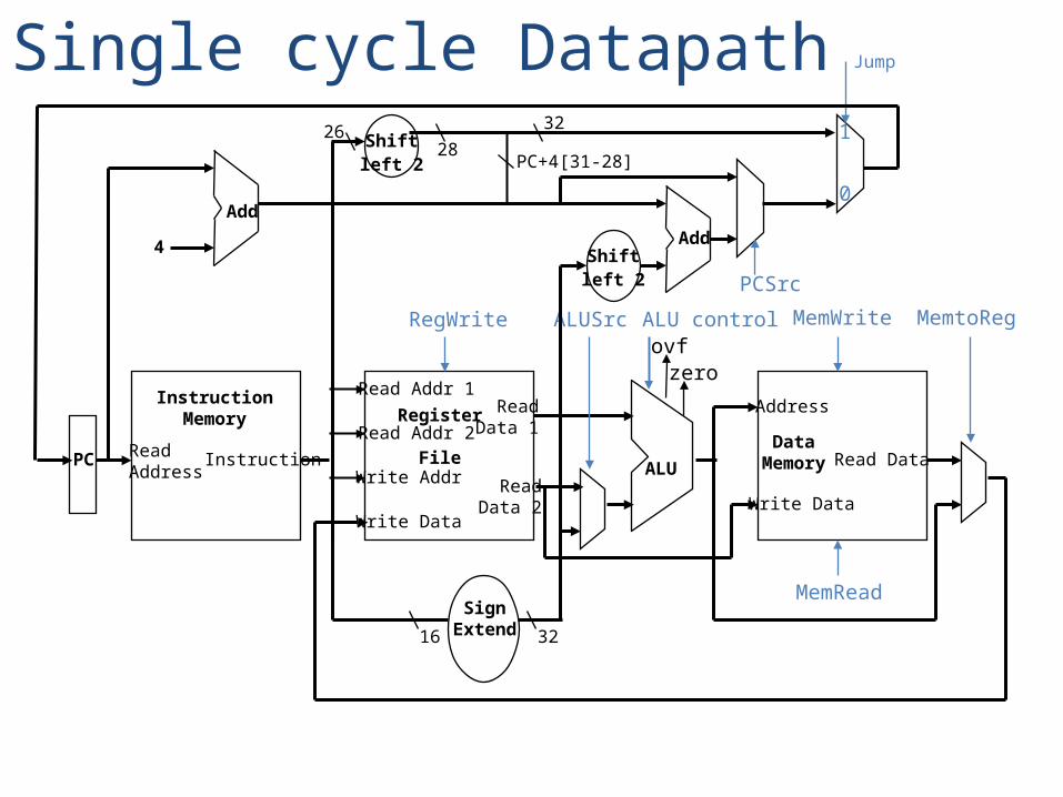
Single cycle Datapath + Control
ReadAddress
Instr[31-0]
InstructionMemory
Add
PC
4
Write Data
Read Addr 1
Read Addr 2
Write Addr
Register
File
Read Data 1
Read Data 2
ALU
ovf
zero
RegWrite
DataMemory
Address
Write Data
Read Data
MemWrite
MemRead
SignExtend16 32
MemtoReg
ALUSrc
Shiftleft 2
Add
PCSrc
RegDst
ALUcontrol
1
1
1
00
0
0
1
ALUOp
Instr[5-0]
Instr[15-0]
Instr[25-21]
Instr[20-16]
Instr[15 -11]
ControlUnit
Instr[31-26]
Branch
Shiftleft 2
0
1
Jump
3226PC+4[31-28]
28
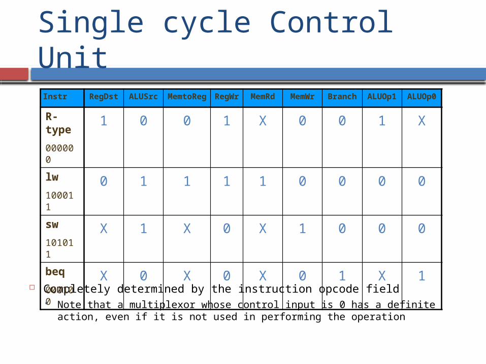
Single cycle Control Unit
Completely determined by the instruction opcode field Note that a multiplexor whose control input is 0 has a definite action,
even if it is not used in performing the operation
Instr RegDst ALUSrc MemtoReg
RegWr
MemRd
MemWr
Branch ALUOp1
ALUOp0
R-type
000000
1 0 0 1 X 0 0 1 X
lw
100011
0 1 1 1 1 0 0 0 0
sw
101011
X 1 X 0 X 1 0 0 0
beq
000100
X 0 X 0 X 0 1 X 1
Disadvantages of Single Cycle Implementation
Uses the clock cycle inefficiently – the clock cycle must be timed to accommodate the slowest instruction especially problematic for more complex
instructions like floating point multiply Is wasteful of area since some functional
units must be duplicated since they can not be “shared” during an instruction execution e.g., need separate adders to do PC update
and branch target address calculations, as well as an ALU to do R-type arithmetic/logic operations and data memory address calculations
How to make it fast?
Parallelism Short-cuts or Caching, or Bypassing Prediction Skip some work
First form of parallelism is Pipelining
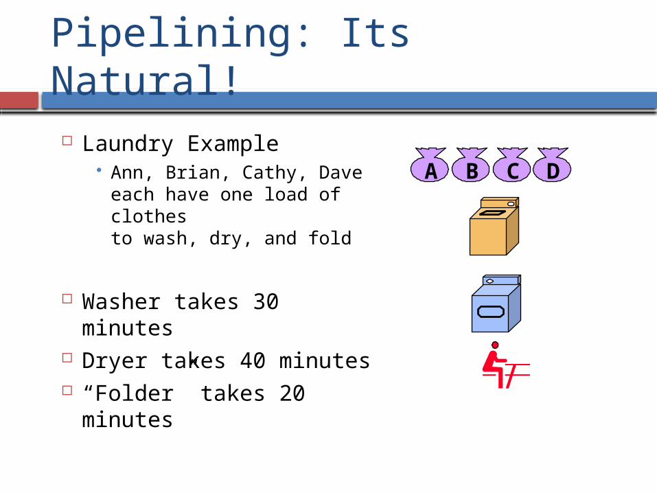
Pipelining: Its Natural!
Laundry Example Ann, Brian, Cathy, Dave
each have one load of clothes to wash, dry, and fold
Washer takes 30 minutes Dryer takes 40 minutes “Folder” takes 20 minutes
A B C D
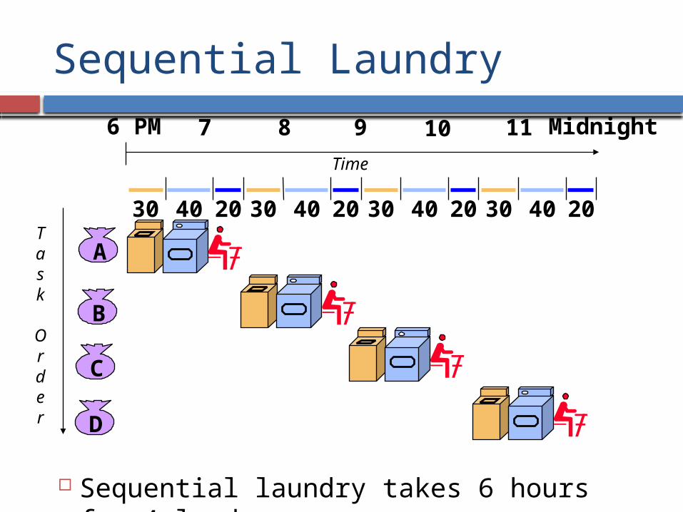
Sequential Laundry
Sequential laundry takes 6 hours for 4 loads
A
B
C
D
30 40 2030 40 2030 40 2030 40 20
6 PM 7 8 9 10 11 Midnight
Task
Order
Time
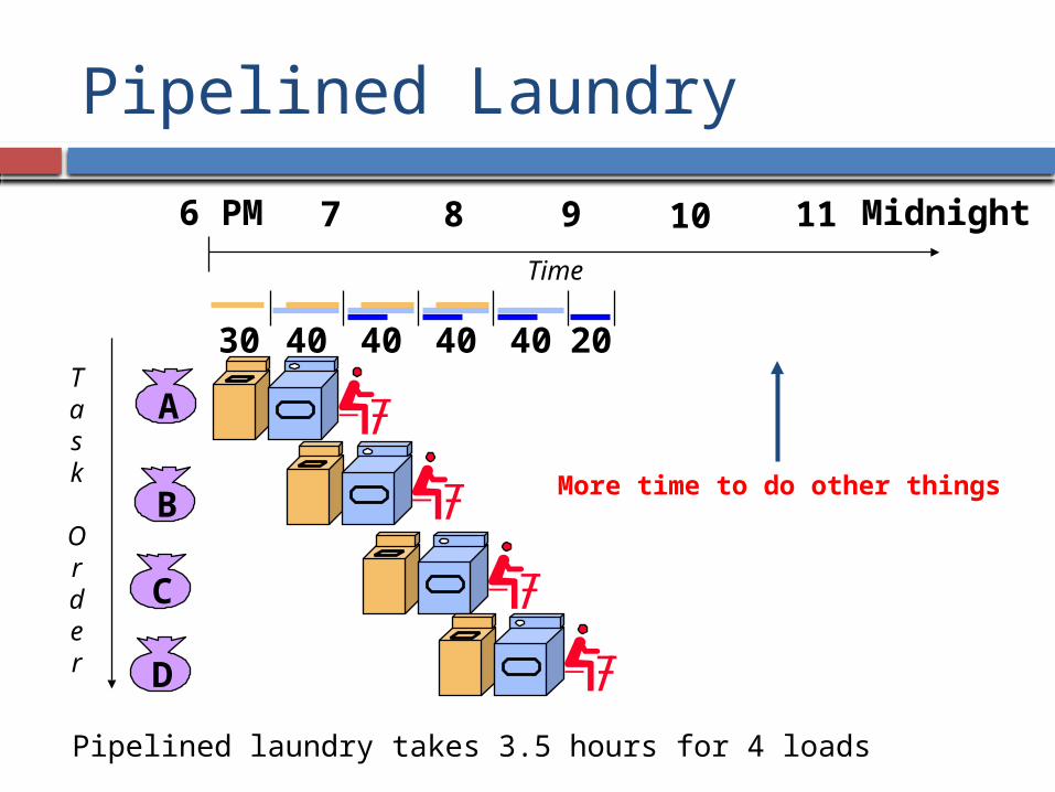
Pipelined Laundry
Pipelined laundry takes 3.5 hours for 4 loads
A
B
C
D
6 PM 7 8 9 10 11 Midnight
Task
Order
Time
30 40 40 40 40 20
More time to do other things
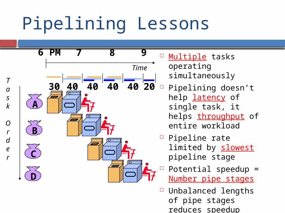
Pipelining Lessons
Multiple tasks operating simultaneously
Pipelining doesn’t help latency of single task, it helps throughput of entire workload
Pipeline rate limited by slowest pipeline stage
Potential speedup = Number pipe stages
Unbalanced lengths of pipe stages reduces speedup
Also, need time to “fill” and “drain” the pipeline.
A
B
C
D
6 PM 7 8 9
Task
Order
Time
30 40 40 40 40 20
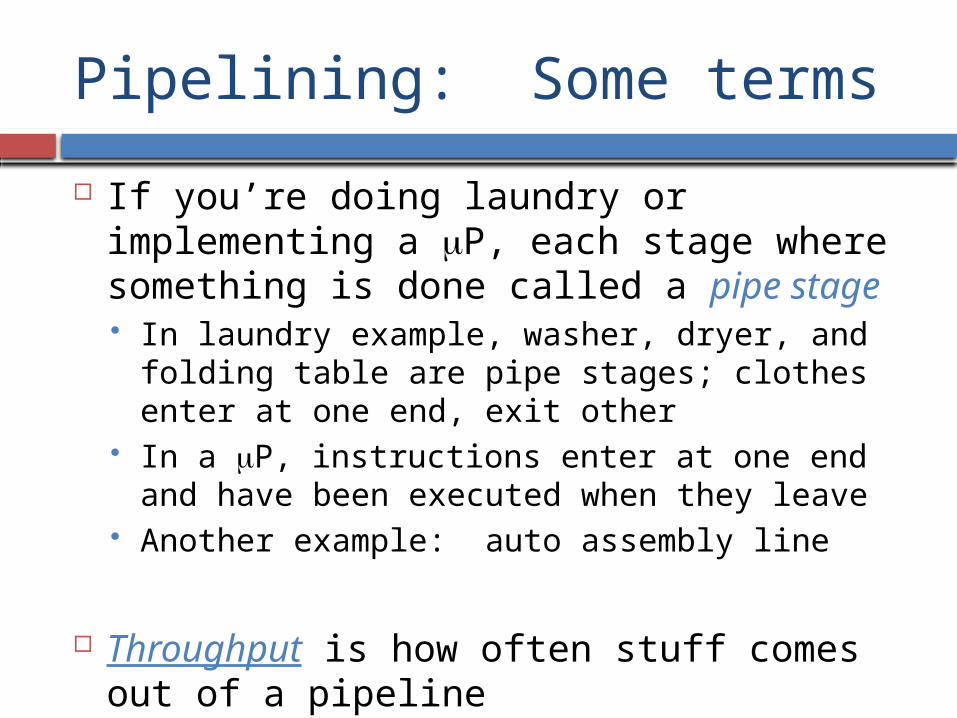
Pipelining: Some terms
If you’re doing laundry or implementing a mP, each stage where something is done called a pipe stage In laundry example, washer, dryer, and folding
table are pipe stages; clothes enter at one end, exit other
In a mP, instructions enter at one end and have been executed when they leave
Another example: auto assembly line
Throughput is how often stuff comes out of a pipeline
Technical details
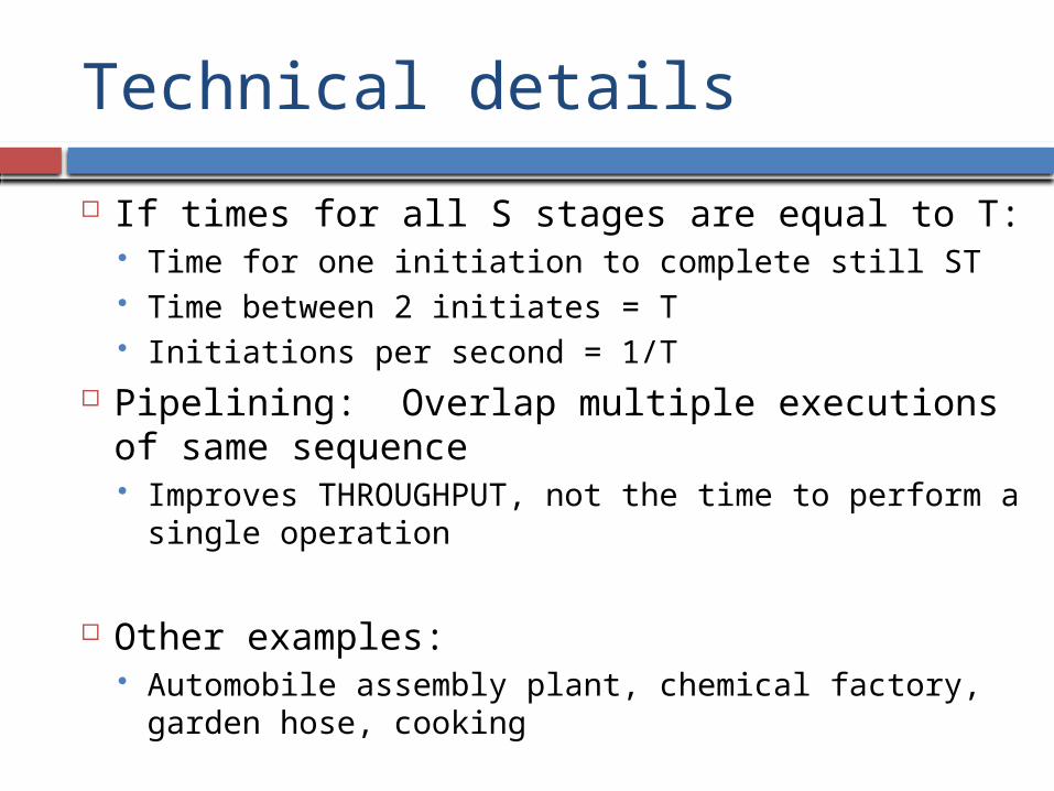
If times for all S stages are equal to T: Time for one initiation to complete still ST Time between 2 initiates = T Initiations per second = 1/T
Pipelining: Overlap multiple executions of same sequence Improves THROUGHPUT, not the time to perform
a single operation
Other examples: Automobile assembly plant, chemical factory,
garden hose, cooking
More technical details
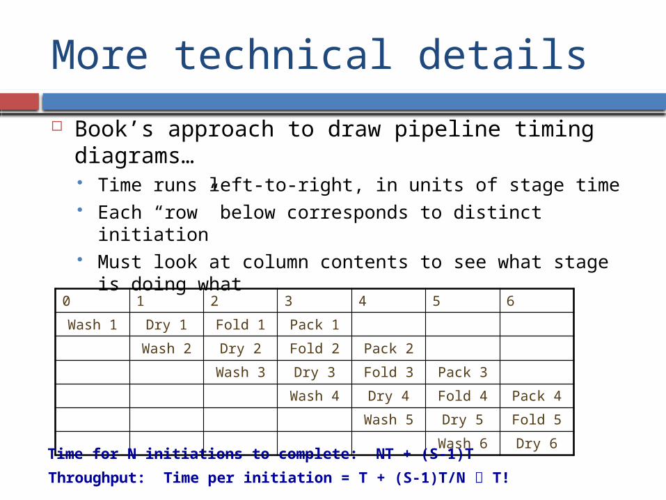
Book’s approach to draw pipeline timing diagrams… Time runs left-to-right, in units of stage time Each “row” below corresponds to distinct initiation Must look at column contents to see what stage is doing
what
0 1 2 3 4 5 6
Wash 1 Dry 1 Fold 1 Pack 1
Wash 2 Dry 2 Fold 2 Pack 2
Wash 3 Dry 3 Fold 3 Pack 3
Wash 4 Dry 4 Fold 4 Pack 4
Wash 5 Dry 5 Fold 5
Wash 6 Dry 6Time for N initiations to complete: NT + (S-1)T
Throughput: Time per initiation = T + (S-1)T/N T!
Ideal pipeline speedup
Latch
combinationallogic
delay = t
combinationallogic
delay = t
combinationallogic
delay = t
combinationallogic
delay = t
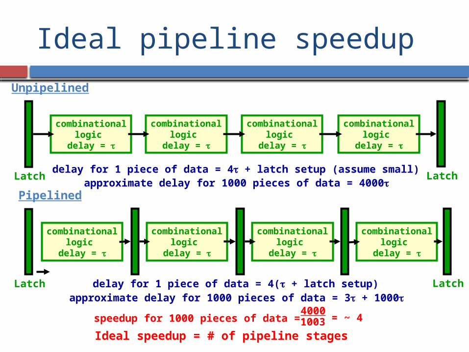
Unpipelined
Latchdelay for 1 piece of data = 4t + latch setup (assume small)
approximate delay for 1000 pieces of data = 4000t
Latch
combinationallogic
delay = t
combinationallogic
delay = t
combinationallogic
delay = t
combinationallogic
delay = t
Pipelined
Latchdelay for 1 piece of data = 4(t + latch setup)approximate delay for 1000 pieces of data = 3t + 1000t
Ideal speedup = # of pipeline stages
speedup for 1000 pieces of data = 4000
= ~ 41003
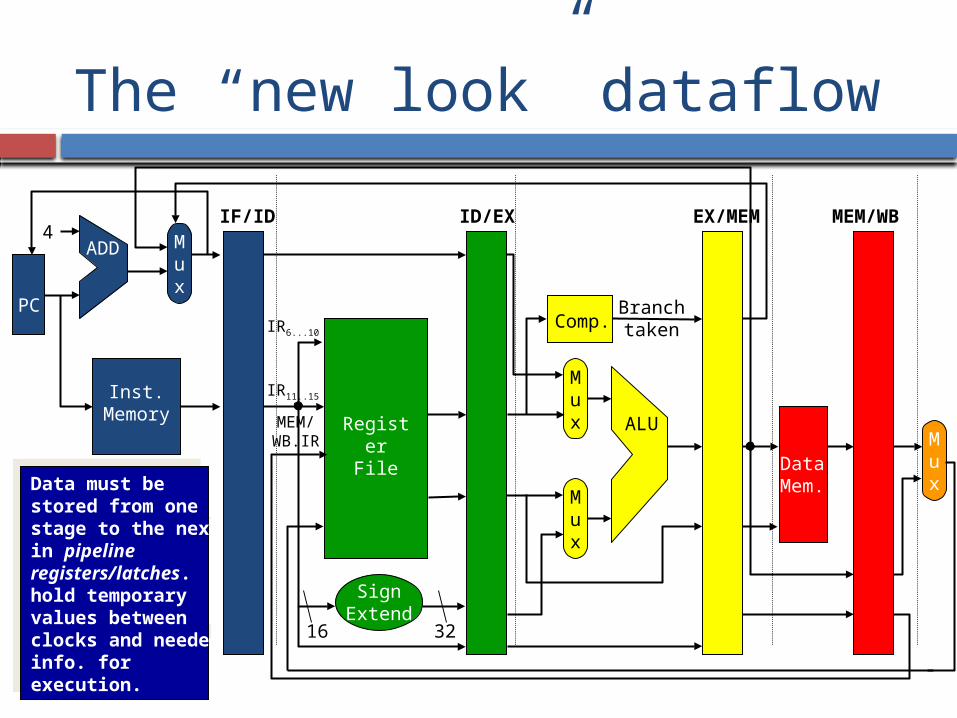
The “new look” dataflow
PC
Inst.Memory
4ADD
RegisterFile
SignExtend
16 32
Mux
Mux
Comp.
ALU
Branchtaken
Mux
DataMem.
IR6...10
IR11..15
MEM/WB.IR
Mux
IF/ID ID/EX EX/MEM MEM/WB
Data must be stored from one stage to the nextin pipeline registers/latches.hold temporaryvalues betweenclocks and neededinfo. for execution.
Data must be stored from one stage to the nextin pipeline registers/latches.hold temporaryvalues betweenclocks and neededinfo. for execution.
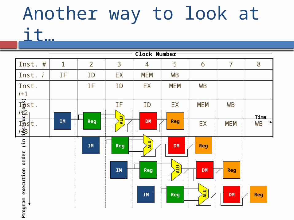
Another way to look at it…
Inst. # 1 2 3 4 5 6 7 8
Inst. i IF ID EX MEM WB
Inst. i+1
IF ID EX MEM WB
Inst. i+2
IF ID EX MEM WB
Inst. i+3
IF ID EX MEM WB
Clock Number
AL
URegIM DM Reg
AL
URegIM DM Reg
AL
U
RegIM DM Reg
AL
U
RegIM DM Reg
Pro
gra
m e
xecu
tion
ord
er
(in
in
str
ucti
on
s)
Time
Questions about control signals Following discussion relevant to a single
instruction
Q: Are all control signals active at the same time?
Q: Can we generate all these signals at the same time?
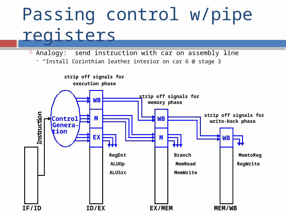
Passing control w/pipe registers
Analogy: send instruction with car on assembly line “Install Corinthian leather interior on car 6 @ stage 3”
WB
M
EX
WB
M WB
Control
IF/ID ID/EX EX/MEM MEM/WB
Inst
ruc
t io
n
RegDst
ALUOp
ALUSrc
Branch
MemRead
MemWrite
MemtoReg
RegWrite
strip off signals for
execution phase
strip off signals for write-back phase
strip off signals for memory phase
Genera-tion
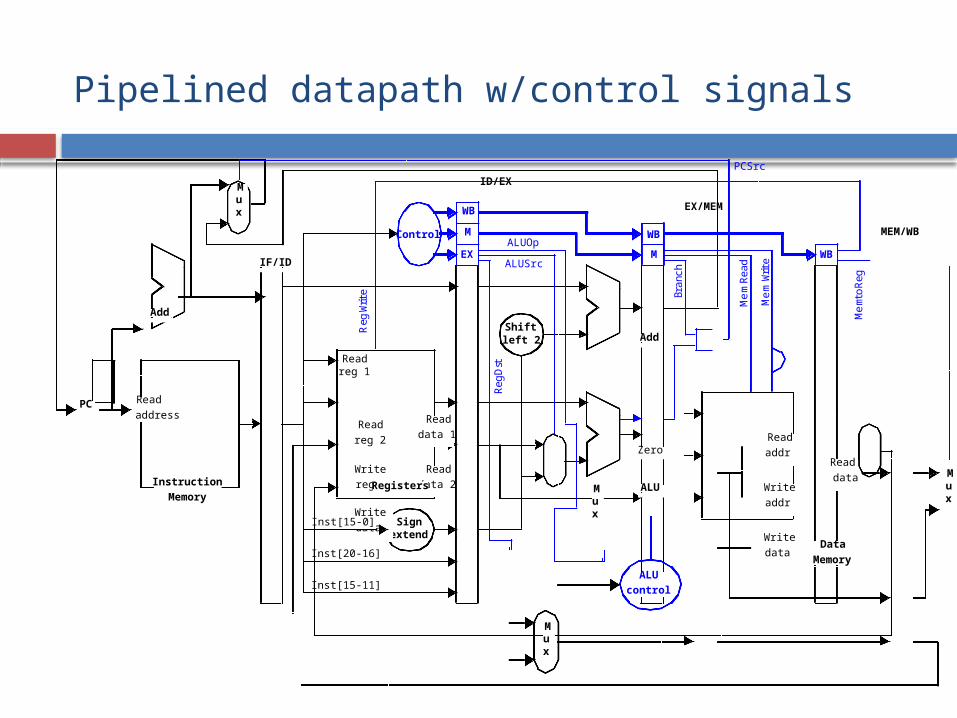
Pipelined datapath w/control signals
Readreg 1
Shiftleft 2
Signextend
Instruction
Memory
Read
addressRead
reg 2
Write
reg
Write
data
Read
data 1
Read
data 2
Read
addr
Write
addr
Write
data
Read
dataALU
Add
Add
Zero
Mux
Mux
Mux
PC
Data
Memory
Mux
IF/ID
EX/MEM
ID/EX
MEM/WB
ALU
control
Reg
Wr i
te
ALUSrc
Bra
nch
Mem
Wr it
e
Mem
toR
eg
Reg
Dst
ALUOp
Mem
Rea
d
PCSrc
Inst[15-0]
Inst[20-16]
Inst[15-11]
Control
WB
M
EX
WB
M WB
Registers
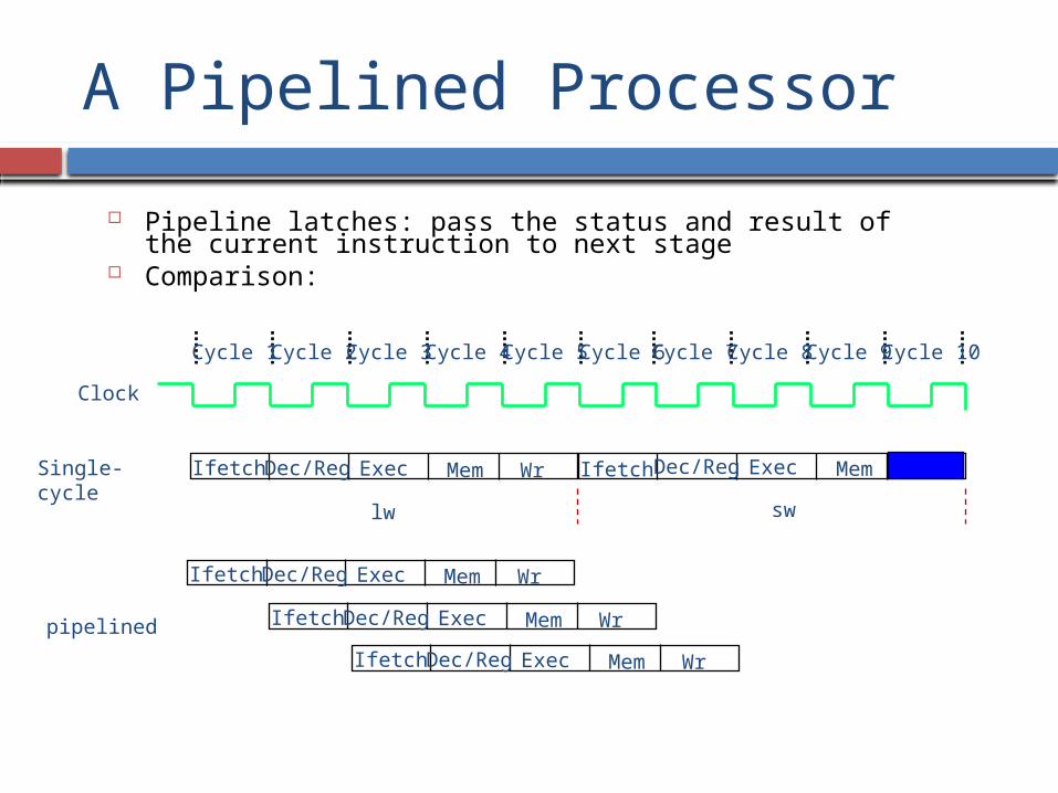
A Pipelined Processor
Pipeline latches: pass the status and result of the current instruction to next stage
Comparison:
Clock
Cycle 1 Cycle 2 Cycle 3 Cycle 4 Cycle 5 Cycle 6 Cycle 7 Cycle 8 Cycle 9 Cycle 10
Ifetch
lw sw
Dec/Reg Exec Mem Wr Dec/Reg Exec MemIfetchSingle-cycle
Ifetch Dec/Reg Exec Mem Wr
Ifetch Dec/Reg Exec Mem Wr
Ifetch Dec/Reg Exec Mem Wr
pipelined