Embed Size (px)
Citation preview
JIF 419
Materials Science
Course Manager: Assoc Prof Dr Saw Kim Guan
Textbook: Materials Science and Engineering (4th
Ed) by Callister & Rethwisch

Academic Planner
• 2 assignments: 30 Nov 2015 (1st assignment)
15 Feb 2016 (2nd assignment)
• Web-conference sessions: 3 before Intensive
• Intensive course (19 Jan 2016 - 7 Feb 2016)
• Continuous Examination: types of materials, atomic structure, bonding in solids, crystal structures, crystallographic points, directions and planes, point defects
• The contributions of course work and examinations:
Final Exam: 70%
Assignments: 10%
Continuous exam: 20%
2
Classification of materials(metals)
• Atoms in metals are very orderly and dense
• Metallic materials have large numbers of non-localized electrons (electrons NOT bound to particular atoms)
• These delocalized electrons make metals to be good electrical & heat conductor and NOT transparent to visible light.
Classification of materials(ceramics)
• Ceramics are compounds b/w metallic & non-metallic elements
• Mostly oxides, nitrides and carbides
• e.g. aluminium oxide, silicon dioxide, silicon carbide, silicon nitride, porcelain
• Hard, brittle, strong, able to stand heat
• Modern usage – engine parts, cookware, cutlery
Classification of materials(polymers)
• Many polymers are organic compounds that are chemically based on carbon, hydrogen and non-metallic elements
• Consist of very large molecular structures, often chainlike and have a backbone of carbon atoms
• e.g. nylon, polyethylene, silicone rubber
• Ductile and pliable, relatively inert chemically
• Low electrical conductivity and non-magnetic
Classification of materials(composites)
• Composites consists of two or more individual materials
• Designed to achieve a combination of properties that is not present in any single material
• designed to incorporate the best characteristics of each of the component material
• E.g. fibreglass – strong, low density
• Modern usage – sport equipment, engine parts
7
Atomic Structure
• Some of the following properties
1) Electrical
2) Thermal
3) Optical
are determined by electronic structure

8
Electron Configurations• Valence electrons – electrons in unfilled shells
• Filled shells more stable
• Valence electrons are most available for bonding and tend to control the chemical properties
– example: C (atomic number = 6)
1s2 2s2 2p2
valence electrons
9
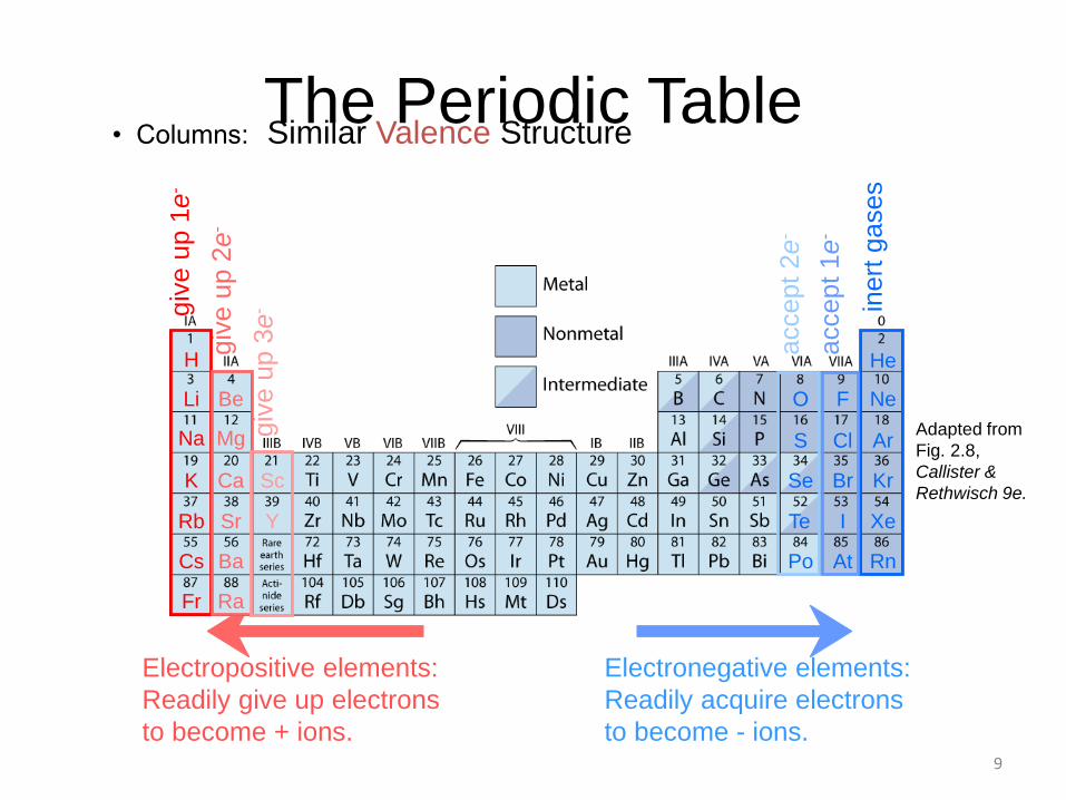
The Periodic Table• Columns: Similar Valence Structure
Adapted from
Fig. 2.8,
Callister &
Rethwisch 9e.
Electropositive elements:
Readily give up electrons
to become + ions.
Electronegative elements:
Readily acquire electrons
to become - ions.
giv
e u
p 1
e-
giv
e u
p 2
e-
giv
e u
p 3
e- in
ert
gases
accept 1e
-
accept 2e
-
O
Se
Te
Po At
I
Br
He
Ne
Ar
Kr
Xe
Rn
F
ClS
Li Be
H
Na Mg
BaCs
RaFr
CaK Sc
SrRb Y
10
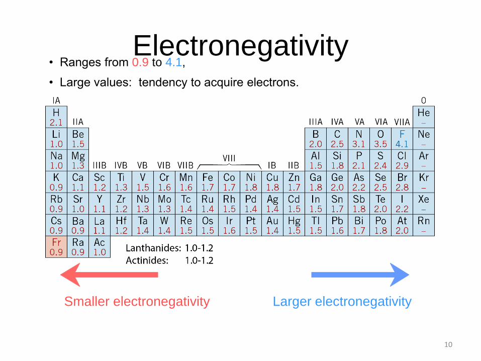
• Ranges from 0.9 to 4.1,
Smaller electronegativity Larger electronegativity
• Large values: tendency to acquire electrons.
Electronegativity
11
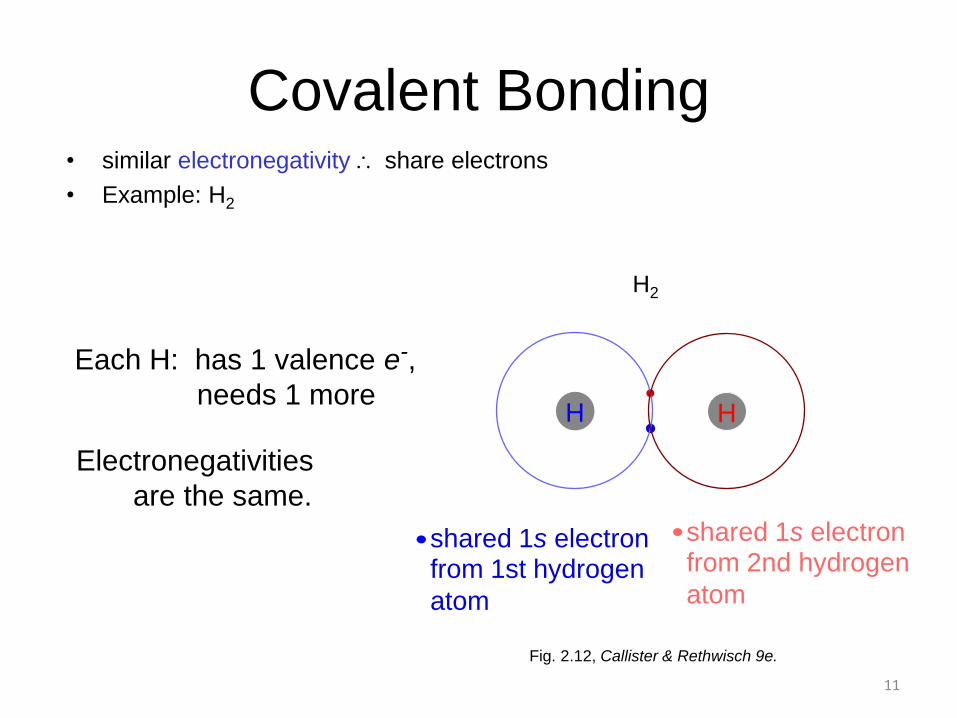
Each H: has 1 valence e-,
needs 1 more
Electronegativities
are the same.
Fig. 2.12, Callister & Rethwisch 9e.
Covalent Bonding• similar electronegativity share electrons
• Example: H2
shared 1s electronfrom 2nd hydrogen
atom
H
H2
shared 1s electronfrom 1st hydrogen
atom
H
12
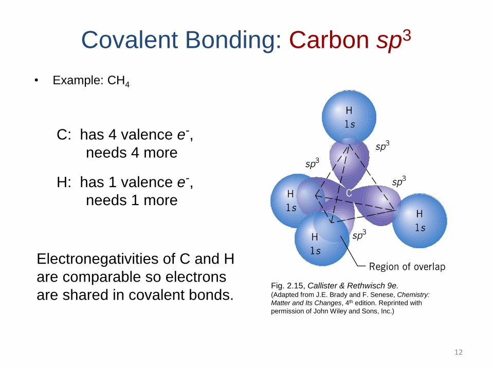
Covalent Bonding: Carbon sp3
• Example: CH4
C: has 4 valence e-,
needs 4 more
H: has 1 valence e-,
needs 1 more
Electronegativities of C and H
are comparable so electrons
are shared in covalent bonds.Fig. 2.15, Callister & Rethwisch 9e.(Adapted from J.E. Brady and F. Senese, Chemistry:
Matter and Its Changes, 4th edition. Reprinted with
permission of John Wiley and Sons, Inc.)

13
Ionic bond – metal + nonmetal
donates accepts
electrons electrons
Dissimilar electronegativities
ex: MgO Mg 1s2 2s2 2p6 3s2 O 1s2 2s2 2p4
[Ne] 3s2
Mg2+ 1s2 2s2 2p6 O2- 1s2 2s2 2p6
[Ne] [Ne]
14
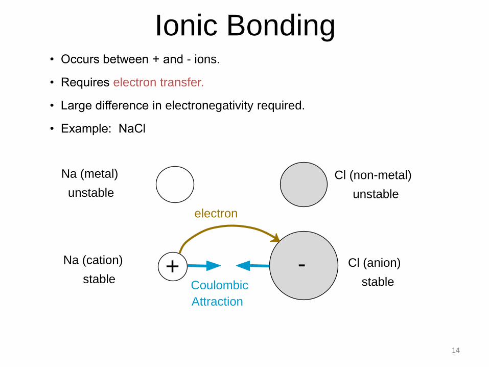
• Occurs between + and - ions.
• Requires electron transfer.
• Large difference in electronegativity required.
• Example: NaCl
Ionic Bonding
Na (metal)
unstable
Cl (non-metal)
unstable
electron
+ -Coulombic
Attraction
Na (cation)
stable
Cl (anion)
stable
15
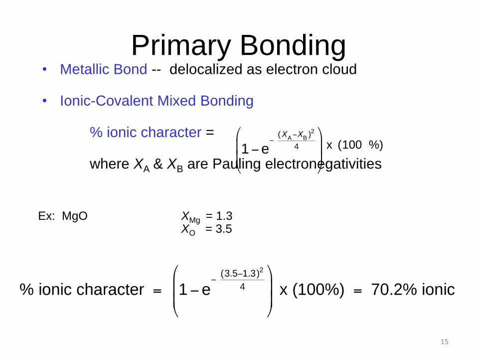
Primary Bonding• Metallic Bond -- delocalized as electron cloud
• Ionic-Covalent Mixed Bonding
% ionic character =
where XA & XB are Pauling electronegativities
%)100(x
Ex: MgO XMg = 1.3XO = 3.5
16
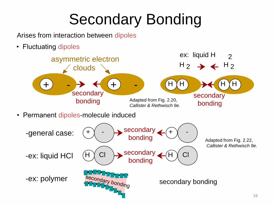
Arises from interaction between dipoles
• Permanent dipoles-molecule induced
• Fluctuating dipoles
-general case:
-ex: liquid HCl
-ex: polymer
Adapted from Fig. 2.20,
Callister & Rethwisch 9e.
Adapted from Fig. 2.22,
Callister & Rethwisch 9e.
Secondary Bonding
asymmetric electronclouds
+ - + -secondary
bonding
HH HH
H 2 H 2
secondary bonding
ex: liquid H 2
H Cl H Clsecondary bonding
secondary bonding
+ - + -
secondary bonding
17
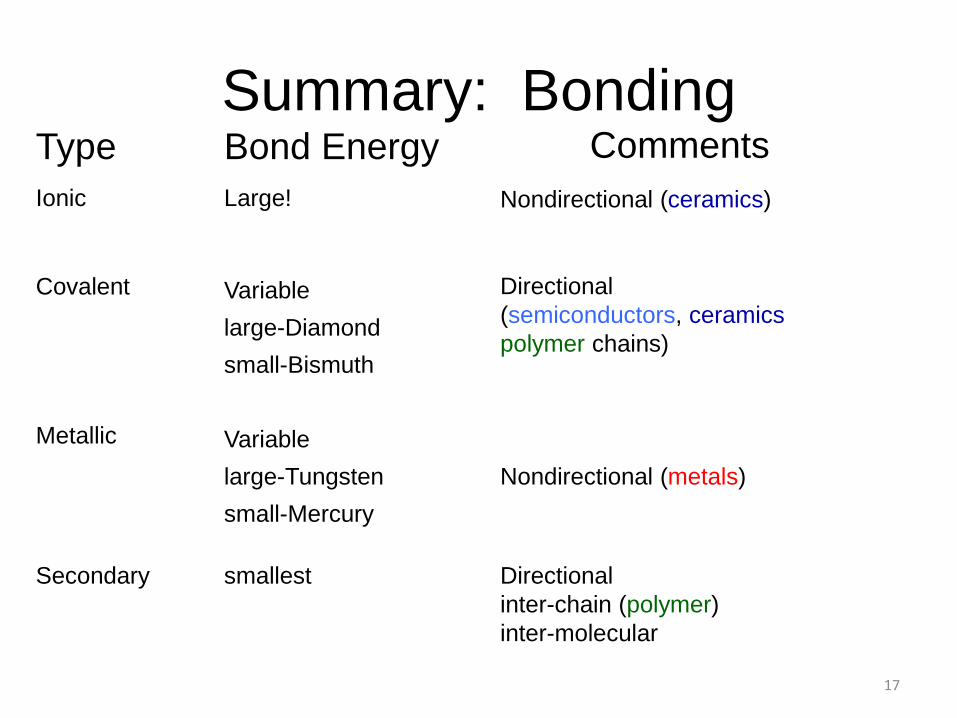
Type
Ionic
Covalent
Metallic
Secondary
Bond Energy
Large!
Variable
large-Diamond
small-Bismuth
Variable
large-Tungsten
small-Mercury
smallest
Comments
Nondirectional (ceramics)
Directional
(semiconductors, ceramics
polymer chains)
Nondirectional (metals)
Directional
inter-chain (polymer)
inter-molecular
Summary: Bonding
18
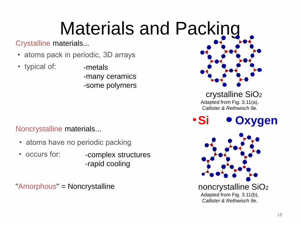
• atoms pack in periodic, 3D arrays
Crystalline materials...
-metals
-many ceramics
-some polymers
• atoms have no periodic packing
Noncrystalline materials...
-complex structures
-rapid cooling
crystalline SiO2
noncrystalline SiO2"Amorphous" = NoncrystallineAdapted from Fig. 3.11(b),
Callister & Rethwisch 9e.
Adapted from Fig. 3.11(a),
Callister & Rethwisch 9e.
Materials and Packing
Si Oxygen
• typical of:
• occurs for:
19
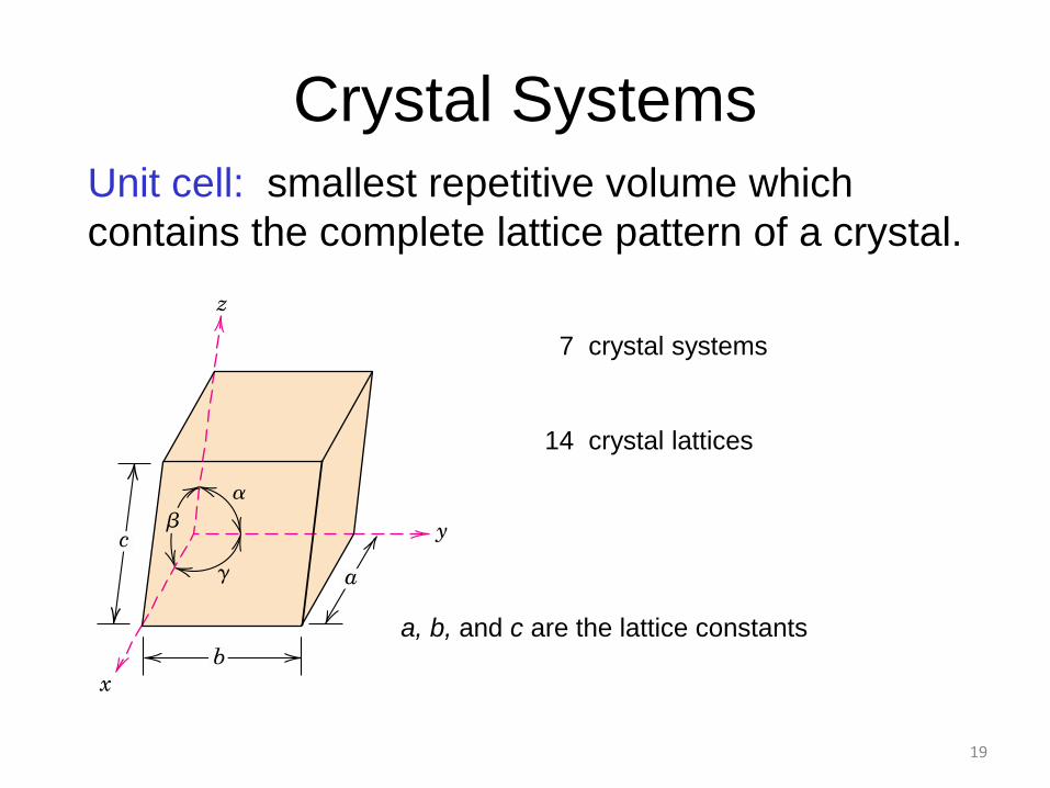
Crystal Systems
7 crystal systems
14 crystal lattices
Unit cell: smallest repetitive volume which
contains the complete lattice pattern of a crystal.
a, b, and c are the lattice constants
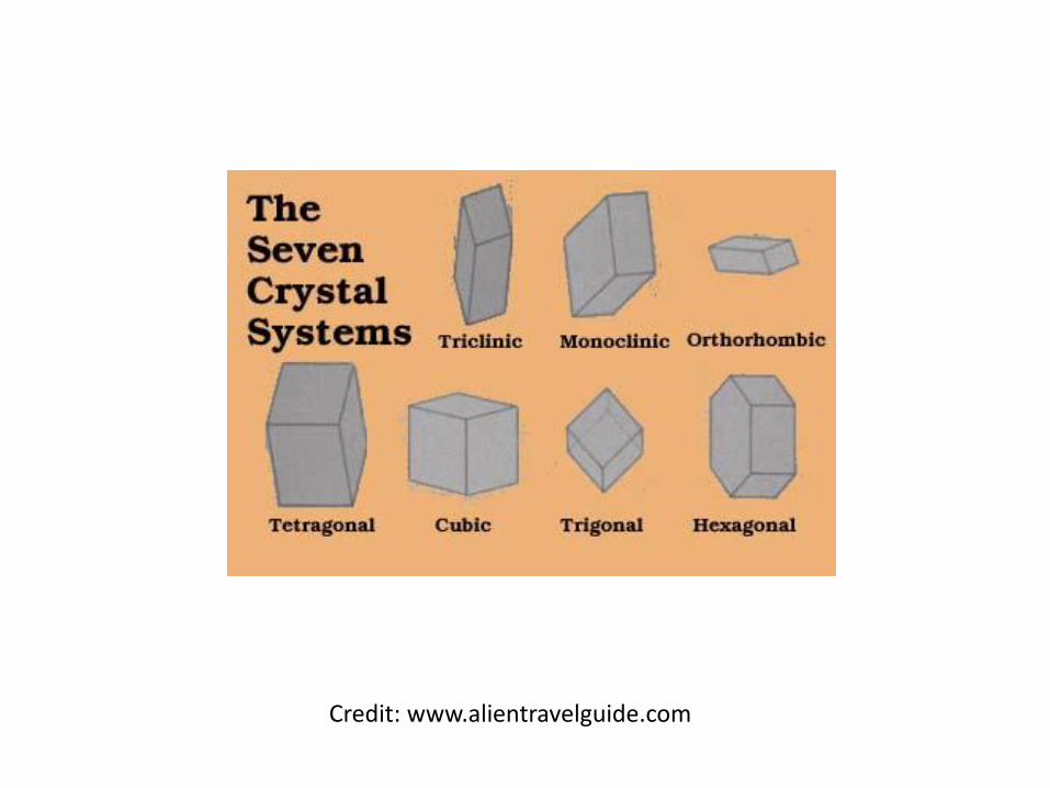
Credit: www.alientravelguide.com
21
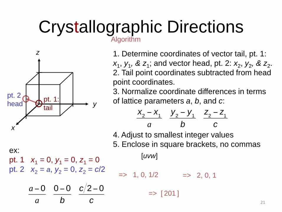
Crystallographic Directions
1. Determine coordinates of vector tail, pt. 1:
x1, y1, & z1; and vector head, pt. 2: x2, y2, & z2.
2. Tail point coordinates subtracted from head
point coordinates.
3. Normalize coordinate differences in terms
of lattice parameters a, b, and c:
4. Adjust to smallest integer values
5. Enclose in square brackets, no commas
[uvw]ex:
pt. 1 x1 = 0, y1 = 0, z1 = 0
=> 1, 0, 1/2
=> [ 201 ]
z
x
Algorithm
y
=> 2, 0, 1
pt. 2
headpt. 1:
tail
pt. 2 x2 = a, y2 = 0, z2 = c/2
22
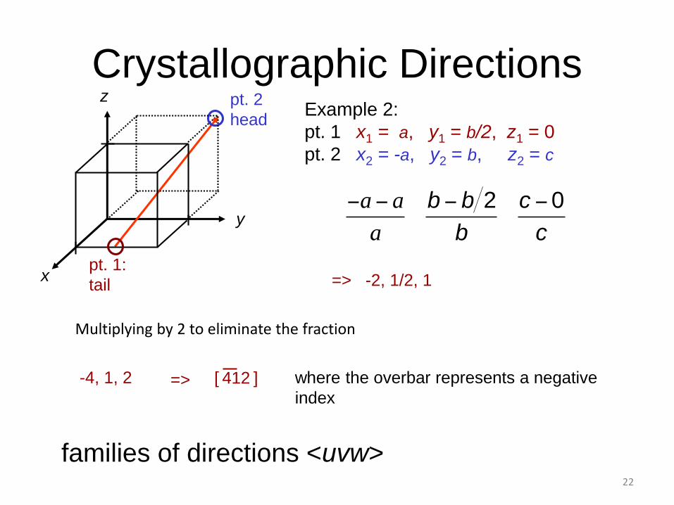
Crystallographic Directions
-4, 1, 2
families of directions <uvw>
z
x
where the overbar represents a negative
index
[ 412 ]=>
y
Example 2:
pt. 1 x1 = a, y1 = b/2, z1 = 0
pt. 2 x2 = -a, y2 = b, z2 = c
=> -2, 1/2, 1
pt. 2
head
pt. 1:
tail
Multiplying by 2 to eliminate the fraction
Crystal Structures
• A lattice is a 3D array of points coinciding with atomic positions
• The atomic order in crystalline solids indicates that small groups of atoms form a repetitivepattern
• The repeat entities are called unit cells
Metallic Crystal Structures
• The atomic bonding is metallic and non-directional in nature
• 3 crystal structures for most common metals –face-centered cubic structure (FCC), body-centered cubic structure & hexagonal close-packed structure

Face-centered cubic structure (FCC)
• Has a unit cell of cubic geometry
• Atoms located at each corner and the centers of all the cubic faces
• The coordination number (the no. of nearest neighbour atoms) is 12
• The atomic packing factor (sum of the sphere volumes of all atoms within a unit cell) is 0.74
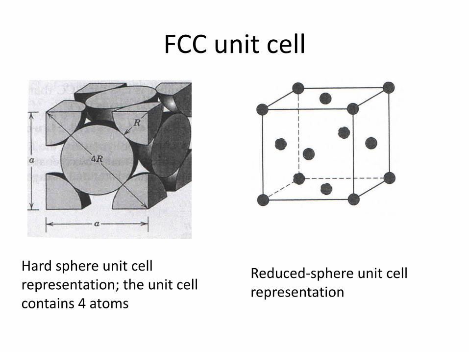
FCC unit cell
Hard sphere unit cell representation; the unit cell contains 4 atoms
Reduced-sphere unit cell representation
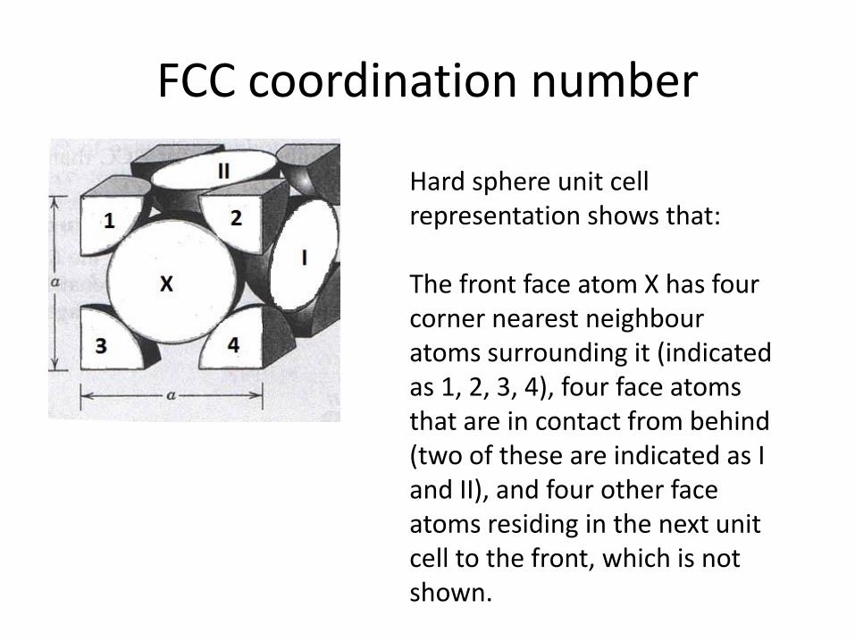
FCC coordination number
Hard sphere unit cell representation shows that:
The front face atom X has four corner nearest neighbouratoms surrounding it (indicated as 1, 2, 3, 4), four face atoms that are in contact from behind (two of these are indicated as I and II), and four other face atoms residing in the next unit cell to the front, which is not shown.
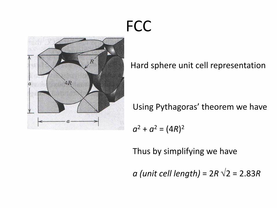
FCC
Hard sphere unit cell representation
Using Pythagoras’ theorem we have
a2 + a2 = (4R)2
Thus by simplifying we have
a (unit cell length) = 2R 2 = 2.83R
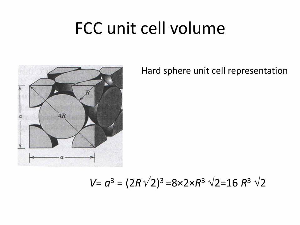
FCC unit cell volume
Hard sphere unit cell representation
V= a3 = (2R 2)3 =8×2×R3 2=16 R3 2
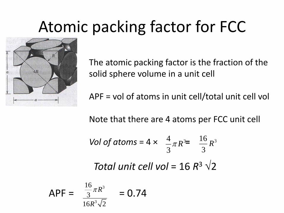
Atomic packing factor for FCC
The atomic packing factor is the fraction of the solid sphere volume in a unit cell
APF = vol of atoms in unit cell/total unit cell vol
Note that there are 4 atoms per FCC unit cell
Vol of atoms = 4 × =
Total unit cell vol = 16 R3 2
34
3R 316
3R
APF = = 0.74 3
3
16
3
16 2
R
R
Body centered cubic structure
• The BCC structure has a cubic unit cell with atoms located at all eight corners and one atom at the cube center
• The single atom at the center is wholly contained within the unit cell
• The coordination number is 8
• The atomic packing factor is 0.68
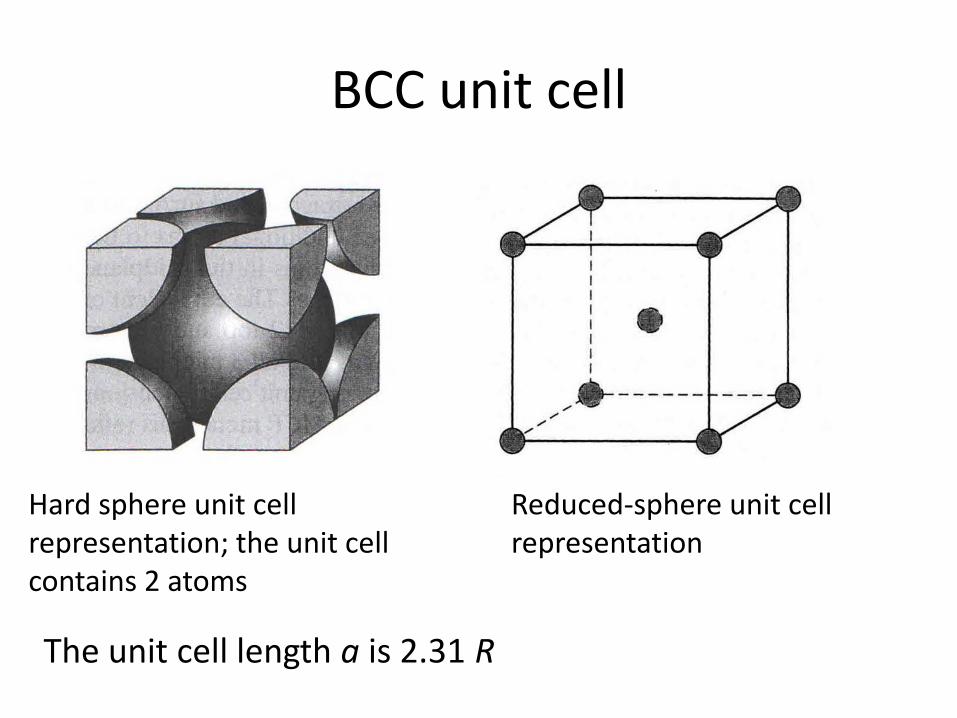
BCC unit cell
Hard sphere unit cell representation; the unit cell contains 2 atoms
Reduced-sphere unit cell representation
The unit cell length a is 2.31 R
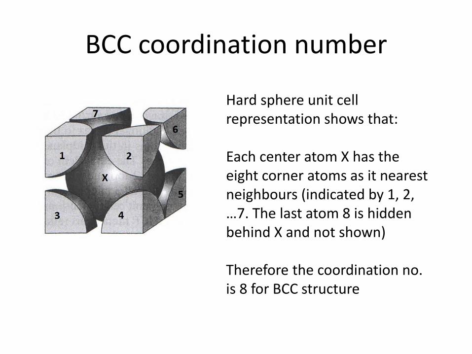
BCC coordination number
Hard sphere unit cell representation shows that:
Each center atom X has the eight corner atoms as it nearest neighbours (indicated by 1, 2, …7. The last atom 8 is hidden behind X and not shown)
Therefore the coordination no. is 8 for BCC structure
34
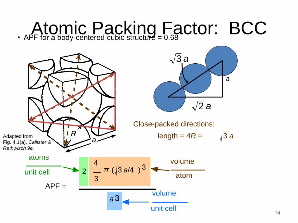
Atomic Packing Factor: BCC
APF =
4
3
π ( 3 a/4 ) 32
atoms
unit cell atom
volume
a 3
unit cell
volume
length = 4R =
Close-packed directions:
3 a
• APF for a body-centered cubic structure = 0.68
aRAdapted from
Fig. 4.1(a), Callister &
Rethwisch 9e.
a
a2
a3
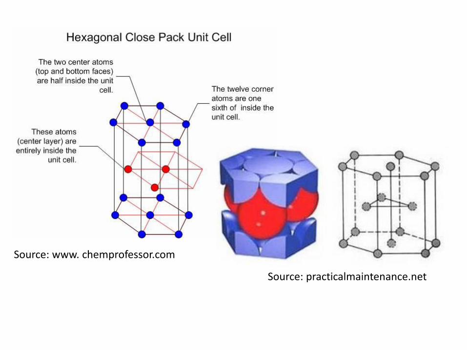
Source: www. chemprofessor.com
Source: practicalmaintenance.net
36
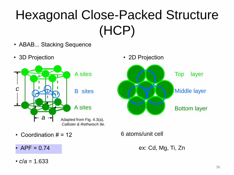
• Coordination # = 12
• ABAB... Stacking Sequence
• APF = 0.74
• 3D Projection • 2D Projection
Adapted from Fig. 4.3(a),
Callister & Rethwisch 9e.
Hexagonal Close-Packed Structure
(HCP)
6 atoms/unit cell
ex: Cd, Mg, Ti, Zn
• c/a = 1.633
c
a
A sites
B sites
A sites Bottom layer
Middle layer
Top layer