Embed Size (px)
DESCRIPTION
HWL - Active Vibration Isolation System Manual (AVI-350/LP) - Supplied by RI UK and Ireland
Citation preview
Instruction manual
Address: Phone: +41 44 776 33 66Fabrik am Weiher Fax: +41 44 776 33 65CH-8909 Zwillikon E-Mail: [email protected] Internet: www.tablestable.biz
ACTIVE VIBRATION ISOLATION System
AAVVII--335500//LLPP

Fabrik am Weiher Phone: +41 44 776 33 66CH-8909 Zwillikon Fax: +41 44 776 33 65Switzerland E-Mail: [email protected]
2
Table of Contents
Safety Instructions ......................................................................................................................3
Accessories ................................................................................................................................3
General.......................................................................................................................................4
Optimum Support Surface ..........................................................................................................5
Choice of Table Top ...................................................................................................................5
AVI-350/LP Control Unit .............................................................................................................6
Attaching Table Top ...................................................................................................................9
Adjustment for Change of Load ................................................................................................10
Operation..................................................................................................................................11
Test of Support Surface............................................................................................................11
BNC Output Jack (Diagnostic Signal) ......................................................................................12
Optional Modulation Input.........................................................................................................13
Installation Checklist .................................................................................................................14
Troubleshooting ........................................................................................................................15
Specifications AVI-350M/LP .....................................................................................................16
Transmissibility .........................................................................................................................17
Dimensions AVI-350S/LP .........................................................................................................18
Dimensions AVI-350M/LP.........................................................................................................19
Sales Offices
Geographical Europe, near and middle East,
Africa, India:
Americas, Australia, New Zealand: Asia:
Georgstrasse 1172119 Ammerbuch,
GermanyPhone: +49-7073-916-796Fax: +49-7073-916-798
e-mail: [email protected]: www.hwlscientific.com
23151 Alcalde Dr. Unit B-3Laguna Hills, Ca 92653
USAPhone: 949-363-2905Fax: 949-340-9751
e-mail: [email protected]: www.herzan.com
18/F., Yokohama Creation Square Bldg.,5-1,
Sakaecho, Kanagawa-Ku Yokohama Kanagawa 221-0052
JapanPhone: +81-45-450-2211Fax: +81-45-450-2221
e-mail: [email protected]: www.herz-f.co.jp

Fabrik am Weiher Phone: +41 44 776 33 66CH-8909 Zwillikon Fax: +41 44 776 33 65Switzerland E-Mail: [email protected]
3
Safety Instructions
The system may only be plugged into a socket with separate ground. Do not disconnect this ground, either at the socket, or by using an ungrounded extension cable.
If you suspect the system to be in any way unsafe, unplug and prevent any possible accidental usage. Contact your nearest service centre.
Before switching on this apparatus make sure that it is connected to the correct mains voltage. Do not remove any cover or allow any metal objects to enter the ventilation slits.
Disconnect from mains before removing any covers. Refer servicing to qualified personnel.
Do not use in potentially explosive surroundings.
The fuses are located in the power socket on the rear side of the control unit.Do not attempt to change a fuse without first unplugging from the mains. Only replace a fuse with the correct type. Never try to bypass a fuse.
Make sure the ventilation slits in the control unit are not covered and that air can freely circulate. Blocking the slits can lead to overheating which could cause a fire.
Notes on equipment safety
The vibration isolation system AVI-350/LP has been designed, manufactured and tested to conform to the safety regulations for measurement- and control-equipment DIN EN 61010-1 (IEC 1010-1) and satisfies the relevant requirements of EEC Directive 73/23.The system conforms to EEC Directive 89/336 (electro-magnetic compatibility). The operator should read this manual which contains important warnings and information.
Accessories
1 Hex Key 2mm1 Spanner 10mm1 Power Cable2 D-Sub 15 Cables1 Instruction Manual
Fabrik am Weiher Phone: +41 44 776 33 66CH-8909 Zwillikon Fax: +41 44 776 33 65Switzerland E-Mail: [email protected]
4
General
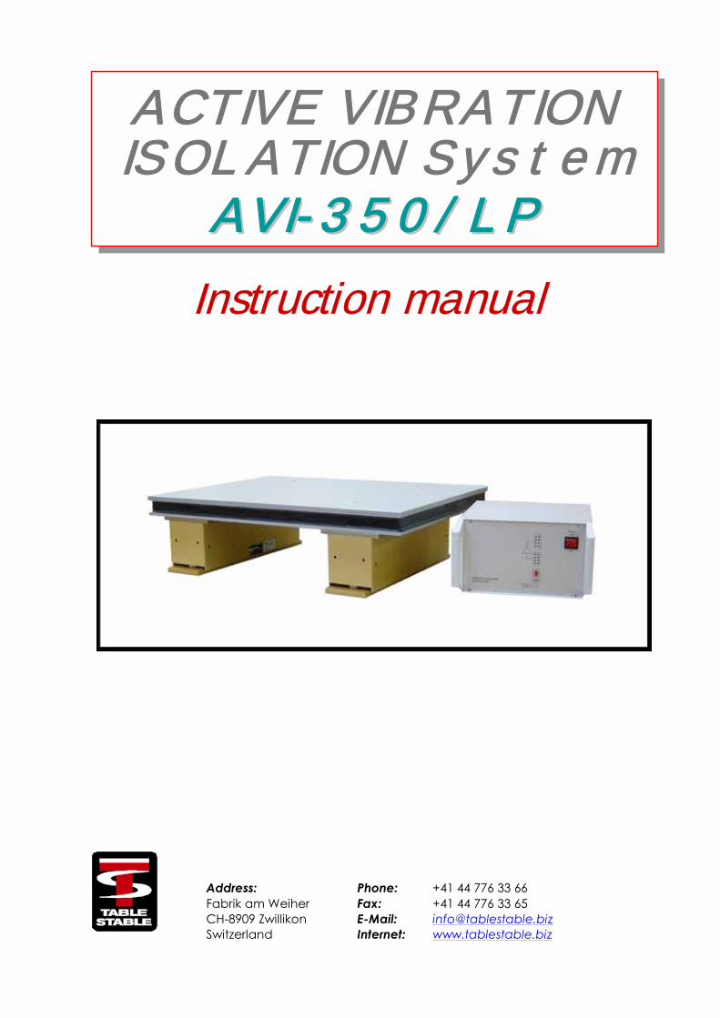
Fig1
This moderately priced dynamic vibration isolation system achieves in a very small volume better isolation than is possible with the biggest and most expensive passive systems. Inertial feedback is used via force transducers to provide not only isolation from building vibrations, but also isolation from vibration sources placed on the system itself. This means, for example, that a delicate microscope isolated by the system will remain at rest despite forces being applied via the operator's hands.
The inherent stiffness of the system, typically 500 times greater than that of a 1 Hz resonance passive isolator, imparts excellent directional and positional stability.
The lack of any low frequency resonance, a resonance which plagues all passive systems, allows the systems to be stacked for super-isolation in severe environments.
Applications include use as a standard stable table for loads of 0-350kg as illustrated in Figure 1. The system is ideal for supporting delicate Fabry-Perot interferometers and tunnel-microscopes, allowing the ultimate performance to be achieved from these and other high resolution instruments. The tables have also proved to be extremely successful for supporting sensitive experiments, such as the troughs for liquids used in measurements on Langmuir-Blodgett films.
AVI-350/LP is an adaptable system consisting of two modules. Each module by itself isolates against vertical and horizontal translations and against rotations about one horizontal axis. The combination of two modules isolates against all six possible translational and rotational vibrations. The modules cannot be used separately.
Isolation of the standard AVI-350/LP system begins at about 2Hz, increasing rapidly to at least 35dB beyond 10Hz. This system offers excellent isolation in the typical laboratory environment.
Fabrik am Weiher Phone: +41 44 776 33 66CH-8909 Zwillikon Fax: +41 44 776 33 65Switzerland E-Mail: [email protected]
5
Optimum Support Surface
To obtain the optimum performance from the system it must be supported on a surface which is as rigid as possible. The best possible is to put AVI-350/LP directly on the floor. However for most applications this will not be practical, and some support structure will be required to bring the system to a convenient operating height. Most simple table structures will be rigid enough vertically, but will leave much to be desired horizontally. The addition of diagonal struts between the table legs can improve the situation dramatically.
It is good to bear in mind that any support structure will follow the building vibrations exactly up to some certain cut off frequency at which point the structure goes into resonance and amplifies the vibration amplitudes. A good structure will have its lowest resonance frequency well above 100Hz.
It is an unfortunate fact of life that the amplitudes of the vertical vibrations of the building (dominantly bending modes of the floor) are largest in the centre of the floor, where for convenience most experiments are situated!
Since the table AVI-350/LP is quite small a possible location may be on a shelf attached to a building pillar. Good braces will be required to support the shelf. This location has the advantage that the vertical vibrations of the building will be very much reduced.
Choice of Table Top
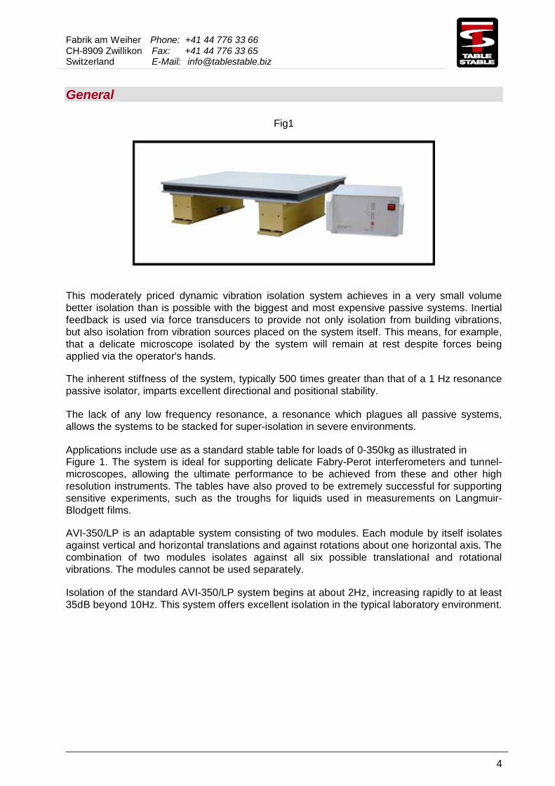
The normal orientation of the isolation units is as shown in Figure 2. It does not matter whether the cable connections are towards the inside or the outside, however pay particular attention to the correct attachment of the table top as discussed below.
Fig 2
The table top must be sufficiently stiff to prevent a relative rotation of the two isolation units about their long horizontal axes. A honeycomb breadboard or an aluminium plate 30mm thick will give best results, but stone plates or even solid wooden boards may be used. For the positions of the attachment holes, see the drilling plan at the end of this document.
Note that it is also possible to attach the isolation units directly to the supported equipment. In this case a rigid mounting is absolutely essential. We will be happy to advise you on the best mounting method.

Fabrik am Weiher Phone: +41 44 776 33 66CH-8909 Zwillikon Fax: +41 44 776 33 65Switzerland E-Mail: [email protected]
6
AVI-350/LP Control Unit
The control unit provides the power for driving the modules. Typically power consumption is less than 5W, rising to 25W in extreme environments. The control unit has an input which may be connected to any AC power point of 115 or 230V ±10%.
Front
1 Power switch2 Power Indicator3 Isolation enable switch4 Isolation enable Indicator5 Output stage overload Indicator
See page 11 for details
1
3
4
5
2

Fabrik am Weiher Phone: +41 44 776 33 66CH-8909 Zwillikon Fax: +41 44 776 33 65Switzerland E-Mail: [email protected]
7
Rear
6 Power socket7 Fuses8 Isolation unit sockets9 Remote socket10 Diagnostic output
87
6
9 10

Fabrik am Weiher Phone: +41 44 776 33 66CH-8909 Zwillikon Fax: +41 44 776 33 65Switzerland E-Mail: [email protected]
8
REMOTE
18
15 9
513
enabled
disabled
ext. disable
560R 3
ext. disable Indicator
6
Pin layout on the rear remote D-Sub 15 socket for AVI-Systems
1 –2 (TXD)3 (GND)4 –5 +8V6 ext. disable Indicator7 –8 –9 (RXD)
10 -8V11 –12 –13 ext. disable14 –15 –

Fabrik am Weiher Phone: +41 44 776 33 66CH-8909 Zwillikon Fax: +41 44 776 33 65Switzerland E-Mail: [email protected]
9
Attaching Table Top
Lower the table top gently into position and slide until the attachment holes in the table top align with the holes in the isolation units. Attach each unit securely with bolts. These bolts should not extend by more than 10mm below the lower surface of the table top.
Do not under any circumstances be tempted merely to rest the table top on the isolation units. This is guaranteed to give poor results.
It may happen that it is inconvenient to put bolts through the table top. In this case it is admissible to use an intermediate plate between units and table top. The intermediate plate should be at least 5mm thick and must be attached in the usual manner to the isolation units. The table top is then attached by screwing upwards through the intermediate plate into the lower surface of the top plate.
If you use this option please note that it is absolutely essential to place grease between the intermediate plate and the table top - failure to do so may result in oscillations between these two plates which will prevent the system from operating.

Fabrik am Weiher Phone: +41 44 776 33 66CH-8909 Zwillikon Fax: +41 44 776 33 65Switzerland E-Mail: [email protected]
10
Adjustment for Change of Load
Each unit of AVI-350/LP can be adjusted to accommodate loads in the range 0 to 175kg. For any setting the load may be varied +/- 30Kg without having to reset the adjustments.
Fig 1
To expose the adjustment nuts, remove the end covers by undoing the screws shown in Fig 1 (2mm hex key).
Fig 3
If an adjustment is needed turn the M6 nuts using the spanner provided. Adjust both springs equally. Moving the spanner to the left raises the units.
Fig 2
Under load the upper gap and the lower gap shown in fig. 2 should be approximately equal. (It is however not essential that the gaps be equal - either gap may be as small as 0.5mm without affecting normal operation, but a small subsequent change of load might cause the unit to move against the stop).
Fig 4
Do not turn the nuts too far or you may damage the units. Under no circumstances should the gap indicated in fig. 4 be greater than 10mm.

Fabrik am Weiher Phone : +41 44 776 33 66CH-8909 Zwillikon Fax: +41 44 776 33 65Switzerland E-Mail: [email protected]
11
Operation
When operating the system for the first time, set the front panel isolation switch to OFF (red knob out). Switch on the power. The power indicator lamp will now light and the 8 display LEDswill briefly flicker. The yellow enable LED will flash on and off at about 2 Hz. If severe vibrations are present or if you place your hand on the table top, some or all of the LEDs will flicker.About 30 seconds after switching on the power, you may push the isolation switch to ON position (red knob in).The yellow LED will now stay permanently on, indicating that the system is isolating.
Place a hand gently on the table top. Probably one or more LEDs in the upper block will come on, indicating an overload. Learn how much force may be applied without causing an overload. If you now apply a lot of force to the table top, all overload lamps will come on and the isolation indicator lamp will flash for a few seconds, indicating that the system is temporarily no longer isolating until the overload is removed (standby mode).
After removing the overload, the isolation lamp should come on again, and the system begins to isolate. Some overload LEDs may come on and persist for a few seconds. Even during this stage the system is isolating - but at reduced gain. After a severe overload the system may take half a minute to reach full isolation, but normally only a few seconds is required.
NOTE: In normal use the isolation switch may be left in the ON position (red knob in). On switching on the power, the yellow lamp will at first flash, indicating the system is in the standby mode. After about 30 seconds the lamp stops flashing and stays on, indicating that the system is now isolating.
Test of Support Surface
With the system operating, push on the support surface. The overload lamps should not light up except possibly for a severe push. If the lamps can easily be made to light up, then the support surface is not sufficiently rigid to obtain full performance. Ascertain whether the support surface reacts more to horizontal or vertical forces and try to stiffen the structure appropriately.Note that the system will operate on any support surface, but a soft structure resonantly amplifies certain building vibration frequencies and these will therefore be less effectively isolated.

Fabrik am Weiher Phone : +41 44 776 33 66CH-8909 Zwillikon Fax: +41 44 776 33 65Switzerland E-Mail: [email protected]
12
BNC Output Jack (Diagnostic Signal)
The rear panel BNC socket gives a multiplexed output showing the signals from all 8 accelerometers. To view this signal on an oscilloscope, set the time base to 20msec and the sensitivity to 1V.
On using the system for the first time it is strongly recommended that you observe this signal, with the isolation switch both ON and OFF - it gives a good impression of how well the system is operating.
H1
H2
V2 V3
H3
H4
BNC OUT
V3
H3
H4
V4
V1
H1
H2
V2
Front Panel LEDs
B
Oscilloscope Display
AVI-350
V1
V2
V3V4
H1H2
H3
H4
V1 V4
A

Fabrik am Weiher Phone : +41 44 776 33 66CH-8909 Zwillikon Fax: +41 44 776 33 65Switzerland E-Mail: [email protected]
13
Optional Modulation Input
To setup the system please note that the isolation-units MUST be placed with the cable sockets facing each other as shown below.
Three BNC inputs, V, H1 and H2 can be provided to allow small vibrations to be introduced into the stabilised table for equipment testing, etc. The directions of these axes are shown below.
H2
H1
CABLES
Care must be exercised when using these inputs to prevent overloading - an overload will not damage the system but produces unwanted table movements. Keep the input signal below about 5Vpp.
An input at any of the BNC rear panel sockets produces a vibration in the appropriate axis. The velocity is approximately constant in the frequency range 2-100Hz. More than one axis may be excited simultaneously.
For a 1 Vpp signal: Velocity approx. 15μm/secDisplacement approx. 1/ω x 15μmAcceleration approx. ω x 15μm /sec2
It is advisable to monitor the display signal on the Diagnostic out BNC while modulating to check correct operation. The signal when viewed with a time scale of 20ms/div should appear as below:
V H1 H2
Note: Pure excitations as indicated here will only occur for frequencies less than about 30Hz.For signal frequencies greater than 30Hz some mixing of the excitation axes will occur

Fabrik am Weiher Phone : +41 44 776 33 66CH-8909 Zwillikon Fax: +41 44 776 33 65Switzerland E-Mail: [email protected]
14
Installation Checklist
Switch on power.Isolation off
Input LEDs should go out and light
if table touched?
If LEDs continually flickersevere vibration level or
forgotten to release transitscrews. If LEDs stay on,
system probably damaged
Push on load-vertically, horizontally Well damped reaction
at rear panel BNC?
Push on topof frame ~50N. Horiz.
LEDs come on?
System ok
Switch Isolation on.All LEDs off?
If LEDs do not go out, thevibration level is too high, orsystem may be damaged, or cables and/or pumping lines
to load are too stiff
yes
no
no
yes
yes
no
Refer to qualifiiedpersonel
Frame too soft or not sitting well.
Push at bottom. LEDsstill come on?
yes noFrame too soft.
Use diagonal braces
Feet not secure. Adjust and tighten. Remove carpet
if present.
yesno
Power LED should come on?
Check power connection.Check fuses in the power socket on the rear panel
no
yes

Fabrik am Weiher Phone : +41 44 776 33 66CH-8909 Zwillikon Fax: +41 44 776 33 65Switzerland E-Mail: [email protected]
15
Troubleshooting
AVI-350M
Is framework sitting firmly?
Are cables and pumping lines flexible
enough?
Is table floating?Adjust all springs, see
page 7 in the Instruction Manual
no
yes
yes
no
Adjust and tighten feet.Set on solid floor
yes
noSecure to frame and/or floor with free-hanging
loops.
The System is ready to go
Fabrik am Weiher Phone : +41 44 776 33 66CH-8909 Zwillikon Fax: +41 44 776 33 65Switzerland E-Mail: [email protected]
16
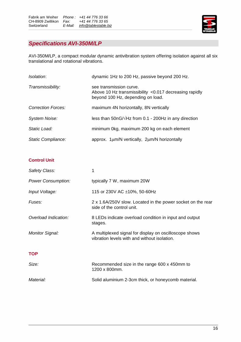
Specifications AVI-350M/LP
AVI-350M/LP, a compact modular dynamic antivibration system offering isolation against all six translational and rotational vibrations.
Isolation: dynamic 1Hz to 200 Hz, passive beyond 200 Hz.
Transmissibility: see transmission curve.Above 10 Hz transmissibility <0.017 decreasing rapidly beyond 100 Hz, depending on load.
Correction Forces: maximum 4N horizontally, 8N vertically
System Noise: less than 50nG/√Hz from 0.1 - 200Hz in any direction
Static Load: minimum 0kg, maximum 200 kg on each element
Static Compliance: approx. 1μm/N vertically, 2μm/N horizontally
Control Unit
Safety Class: 1
Power Consumption: typically 7 W, maximum 20W
Input Voltage: 115 or 230V AC ±10%, 50-60Hz
Fuses: 2 x 1.6A/250V slow. Located in the power socket on the rear side of the control unit.
Overload Indication: 8 LEDs indicate overload condition in input and output stages.
Monitor Signal: A multiplexed signal for display on oscilloscope shows vibration levels with and without isolation.
TOP
Size: Recommended size in the range 600 x 450mm to 1200 x 800mm.
Material: Solid aluminium 2-3cm thick, or honeycomb material.

Fabrik am Weiher Phone : +41 44 776 33 66CH-8909 Zwillikon Fax: +41 44 776 33 65Switzerland E-Mail: [email protected]
17
Transmissibility
AVI-350M
0.01
0.1
1
10
0.1 1 10 100
Frequency [Hz]
Tra
nsm
issi
bili
ty

Fabrik am Weiher Phone : +41 44 776 33 66CH-8909 Zwillikon Fax: +41 44 776 33 65Switzerland E-Mail: [email protected]
18
Dimensions AVI-350S/LP
110,58
4
120
106
8
3763
60
163
163
396
84
64
M5
10 ø6,5
Fabrik am Weiher Phone : +41 44 776 33 66CH-8909 Zwillikon Fax: +41 44 776 33 65Switzerland E-Mail: [email protected]
19
8
110,51
10
13
0
84 92
Ø6,5 M5
M6
24
0
10
60
0
62
0
63
6
24
0
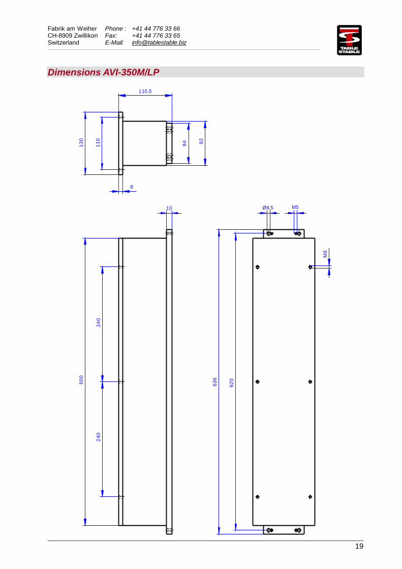
Dimensions AVI-350M/LP


![Fradi teto szakvelemeny 2014 - static.bkv.hustatic.bkv.hu/files/procurements/583_3959.pdfwduwyv]hunh]hwl ydodplqw d kpmd]dw pstwpv]hwl ioodsrwihoppu yl]vjiodwiw pho\qhn](https://img.dokumen.tips/doc/110x75/5cb67acd88c993a7738b9f7b/fradi-teto-szakvelemeny-2014-hunhhwl-ydodplqw-d-kpmddw-pstwpvhwl-ioodsrwihoppu.jpg)
![FV - BGSZC Szily Kálmán Technikum és Kollégium · 2020. 10. 4. · pfvyj\ps ohwjpspv]hwl fv yh]hwpnhn j\dnruodwd psdoj\ps ohwjpspv]hwl dodsr]iv , j\dnruodw psdops ohwjpspv]hwl](https://img.dokumen.tips/doc/110x75/60c5759049e0fb7fd70c9faa/fv-bgszc-szily-klmn-technikum-s-kollgium-2020-10-4-pfvyjps-ohwjpspvhwl.jpg)