Embed Size (px)
Citation preview
1
Chapter 1: Project Overview
1.1 Introduction
Home Automation is automation of home, housework or household activity. In other
words it refers to use of IT/computer to control home appliances. It integrates electrical
devices in a house with each other. For example: It can include centralized control of
lighting, appliances, security lock of gates & doors to provide improved convenience,
comfort, energy, efficiency and safety.
In today's IT world, home automation is being popular due to easiness, flexible means
of viewing/monitoring and controlling the appliances and other things according to
users comfort and needs. The challenging part lies in simplicity and cost of installing
them in home and varies with increasing number of services to be monitored and
controlled. This project named 'HOME AUTOMATION’ is idea of home automation
using android.
The popularity of home automation has been increasing greatly in recent years due to
considerable affordability and simplicity through smartphone and tablet connectivity.
A home automation system integrates electrical devices in a house with each other. The
techniques employed in home automation include those in building automation as well
as the control of domestic activities, such as lighting control system, and the use
of other electrical appliances. Devices may be connected through a home network to
allow control by a personal computer, and may allow remote access from the internet.
Through the integration of information technologies with the home environment,
systems and appliances can communicate in an integrated manner which results in
convenience, energy efficiency, and safety benefits.
Due to the advancement of wireless technology, there are several different of
connections are introduced such as GSM, WIFI, and Bluetooth. Each of the connection
has their own unique specifications and applications. Among the four popular wireless
connections that often implemented in HA project, WIFI is being chosen with its
suitable capability. The capabilities of WIFI are more than enough to be implemented
in the design. Also, most of the current laptop/notebook or Smartphone come with built-
in WIFI adapter. It will indirectly reduce the cost of this system.
2
This project forwards the design of home automation and security system using
Raspberry pi, a credit sized computer. Raspberry pi provides the features of a mini
computer, additional with its GPIO pins where other components and devices can be
connected. GPIO registers of raspberry pi are used for the output purposes. We need
to design a power strip that can be easily connected to GPIO Pins of the Raspberry pi.
The home appliances are connected to the input/output ports of Raspberry pi along with
the power strip and their status is passed to the raspberry pi. The android running OS
in any phone connected to a network can access the status of the home appliances via
an application. It presents the design and implementation of automation system that can
monitor and control home appliances via android phone or tablet.
1.2 Problem Statement
There is a great energy crisis in current situation of our country. Moreover, people have
become negligent in proper utilization of the available energy. People often forget to
turn off the light sources and other home appliance while staying out from home. Even
in those situations, application of home automation makes it possible to control them
from a distant place in easy way with our smartphone.
People are constantly running from place to place, working to accomplish everything
on our never-ending “to-do” list. Because of the home automation system, we never
have to worry about opening the door, switching off the appliances and so on. In short,
we can save precious time and experience more daily productivity.
1.3 Objectives
The main objectives of our project are as follows:
i. To remotely control home appliances and monitor them.
ii. To save time and utilize the energy efficiently.
1.4 Applications
The application includes remote controlling of home appliances and lighting systems
in an easy way. Also, home security and monitoring can be achieved.
3
1.5 Project Features
The features of our project can be highlighted in following points:
i. Remote control of home appliances from anywhere using app.
ii. Continuous monitoring and security of home with camera module.
iii. Considerable reduction in electricity bills with efficient energy utilization.
1.6 Feasibility Analysis
This project can be implemented using affordable electronic and software technology
making it economically, technically and operationally feasible.
1.6.1 Economic Feasibility
This project is based on android phone based and few electronic components like
Raspberry Pi microprocessor, camera modules, relay switches etc. which are affordable,
making it economically feasible to implement.
1.6.2 Technical Feasibility
This project is based on wireless technology and embedded system which are
reasonably in phase with currently used technology. Therefore, it is very much favoured
by the technology.
1.6.3 Operational Feasibility
This software will have very easy to use, user friendly interface so it will be pretty much
operable by anyone having little experience of using android phone. It could be helpful
for physically disabled person too, controlling home appliances with the click of a
button. So it is operationally feasible.
4
1.7 System Requirements
1.7.1 Hardware Requirements
Control electronics
Raspberry Pi as the controller for its processing power and large developer
community.
Relays to connect electrical appliances to low voltage control of Raspberry Pi.
GPIO pins are connected to transistor. Transistors are used as switch.
Wi-Fi dongle to connect Raspberry Pi to the internet/LAN.
Android phone with minimum android version 4.2 Jellybean to run the HA app.
* Details about related hardware can be found on cost estimation section.
1.7.2 Software Requirements
1. Android Development Tools (ADT)
- To build the android application to send the control signals to control the HA
system and to receive the live video feed from the camera.
2. IDLE
-IDE for Python programming used to code the server side program.
3. Raspbian OS
-Linux based OS for Raspberry Pi
4. RPI-GPIO library
- GPIO interface library for the Raspberry Pi.
5. Apache server and MySQL server
- For hosting the webserver and MySQL database in Raspberry Pi
6. Ffmpeg encoder/decoder
- To stream the video to YouTube live stream server.
5
Chapter 2: Literature Review
As per our survey, there exist many systems that can control home appliances using
android based phones/tablets. Each system has its unique features. Currently certain
companies are officially registered and are working to provide better home automation
system features. Following models describes the work being performed by others.
N. Sriskanthan [1] explained the model for home automation using Bluetooth via PC.
But unfortunately the system lacks to support mobile technology.
Muhammad Izhar Ramli [2] designed a prototype electrical device control system using
Web. They also set the server with auto restart if the server condition is currently down.
Hasan [3] has developed a telephone and PIC remote controlled device for controlling
the devices pin check algorithm has been introduced where it was with cable network
but not wireless communication.
Amul Jadhav [4] developed an application in a universal XML format which can be
easily ported to any other mobile devices rather than targeting a single platform.
Pratik Gadtaula of Telemark University College, Faculty of Technology has done a
Master’s thesis on “Home Automation” [5]. This project of his is quite interesting and
challenging on the other hand. The author has developed a home automation system
which is quite similar to the concept we’re trying to implement in our project. His H.A
system has got Raspberry pi tied together with Arduino controller for the controlling of
a number of devices, unlike ours. Similarly, his project has conceptualized to integrate
both the LAN network and Internet for two different aspect of the same project idea,
however has not managed to do so. Also, he uses a website based user side application
for controlling the home appliances through a web browser, this is striking difference
between his project and what we’re trying to do.
Next project we looked up to, was “Android Controlled Home Automation” [6], a
project performed by Sabin Adhikari and co. from Kathmandu Engineering College,
Electronics faculty. What they’ve succeeded to do is built a home automation system
which is controlled by an android app, much like ours, and has Google based voice
command system. Their hardware requirements are closely related to ours. Their work
includes video streaming from an IP camera to the android device and other home
appliances control system. Their project is entirely based on local network connection
using Wi-Fi. This is also a point where our project seems to improve by integrating
6
both local network and Internet connection, to allow remotely control of home
appliances.
Each of these system has their own unique features and on comparison to one another
lacks some advancement.
Apart from the actual projects we consulted, we also did some research on the
background of this field, studied about the basics and foundations necessary to carry
out this project. For instance, we went through the book “Raspberry Pi Home
Automation with Arduino” by Andrew K. Dennis. It’s an excellent read for the
beginners to jump into the field of Home Automation. It deals with the necessary
background details required to build a H.A system. It talks about Raspberry Pi, Arduino
controller, database design and all sorts of things.
Another one good read is “Getting Started with Raspberry Pi” by Matt Richardson and
Shawn Wallace. It covers a great deal of information about the core of our project that
is Raspberry Pi. It deals with lots of things that can be done with a Raspberry Pi. It
explains the procedure of building some simple yet innovative projects with lots of
application packages that come with Raspberry Pi.
Last but not the least, the book “Designing the Internet of Things” by Adrian McEwen
and co. gives a great deal of knowledge on the concept of Internet of Things which
ranges from the day to day examples of IoT based projects, the information of taking
you prototype to manufacturing. This book is really a good take on IT based
entrepreneurship.
Other helpful resources are the online sources like official Raspberry Pi documentation
and resource site [7] which has detailed information about how to get started with the
Raspberry Pi, configuration details, forum discussions and whole lot of useful stuffs
like setting up the apache server on pi. Also, it has information regarding setting up the
Raspberry Pi camera module, taking pictures and video using the Python pi
camera module, connecting a physical button with the GPIO pins and programming it
to control the camera.
Likewise, some YouTube tutorial lessons really helped as well. A really good
explanation for the YouTube live streaming from Raspberry Pi was due to blog of Max
Ogden [8]. Similarly, from the site of tutorials-point [9], we learnt connecting the
MySQL database from Python using MySQLdb library connector. The book on
"Networking and Web application using Raspberry pi, Arduino and Teensy" by Yury
Magda gives the knowledge on connecting raspberry pi with Arduino using serial
7
interface.
Our system has application layer prototype. There is no explicit use of socket
programming to directly connect the android application with the raspberry pi but
instead it is connected with a database which is connected to and hosted by Raspberry
Pi. This further adds security to our system. The data are received only by the server at
the specified port and data are further analysed. Our project is different in a sense it has
its own software level application to control the home appliances. We are trying to
incorporate both LAN and Internet approach to our solution of H.A. So that users at
home can simply connect to their private Wi-Fi and control the H.A system even
without Internet, and when user is away from home he/she can control the system
through Internet. And, also our approach to the solution differs from all other previous
projects in regards to live video streaming and also has lots of improvements in other
areas as well.
8
Chapter 3: Methodology
This section of the report explains about what are we going to do and how are we going
to do it. We will be following incremental development model for the completion of
this project which is discussed below briefly:
Incremental development model
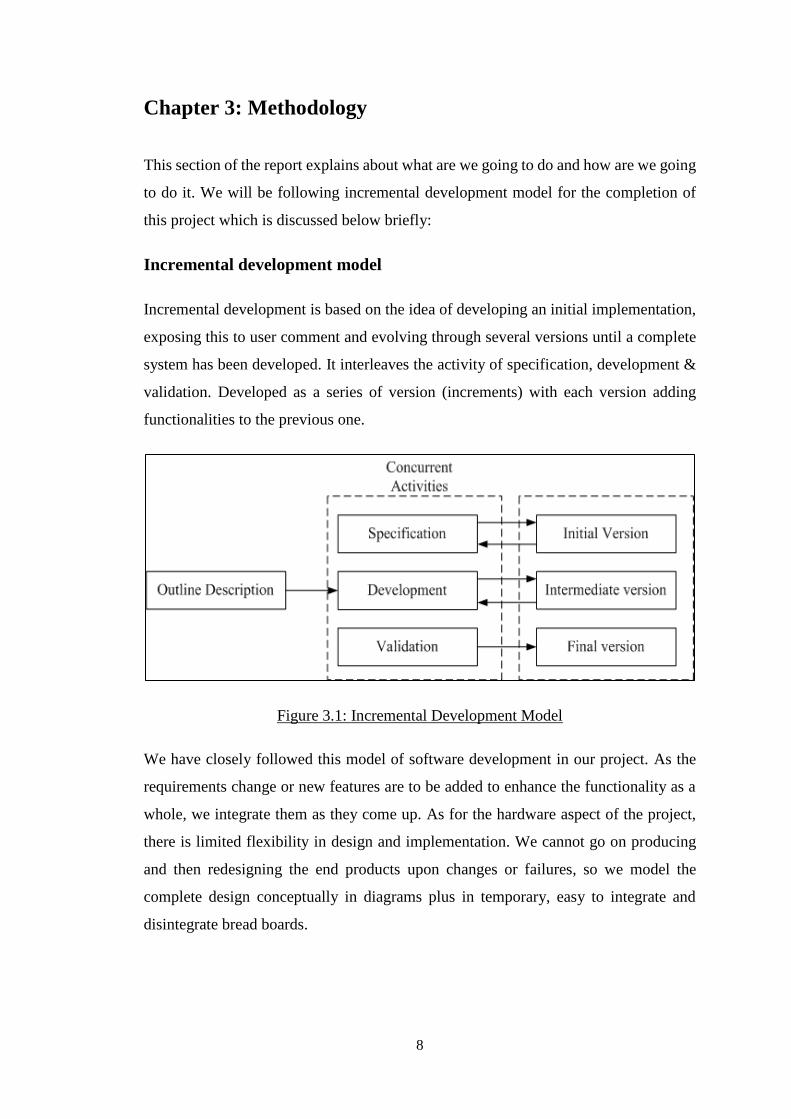
Incremental development is based on the idea of developing an initial implementation,
exposing this to user comment and evolving through several versions until a complete
system has been developed. It interleaves the activity of specification, development &
validation. Developed as a series of version (increments) with each version adding
functionalities to the previous one.
Figure 3.1: Incremental Development Model
We have closely followed this model of software development in our project. As the
requirements change or new features are to be added to enhance the functionality as a
whole, we integrate them as they come up. As for the hardware aspect of the project,
there is limited flexibility in design and implementation. We cannot go on producing
and then redesigning the end products upon changes or failures, so we model the
complete design conceptually in diagrams plus in temporary, easy to integrate and
disintegrate bread boards.
9
Version 1.0
At first, we developed an app with basic facility of making Http requests to the local
Apache server hosted on the PC. This version could make changes to the MySQL
database on the server.
Version 1.1
Next, we uploaded and hosted the MySQL database on the Apache server on the
Raspberry Pi. And, both android app and Raspberry pi were connected over a LAN.
Further, server script was coded on the Raspberry pi to react to the changes made on
MySQL database.
Version 1.2
After that, we integrated the live streaming part to the android app and also on the
Raspberry pi to capture and stream live video to the YouTuber server. Similarly, we
designed and fabricated PCB to interface Raspberry pi with AC appliances.
Final Version
After all these intermediate version, at last, the final version of system was developed.
This version facilitated the database on the cloud and both android app and Raspberry
pi could communicate with each other over the internet. Hence, android app facilitated
remote controlling of appliances with live video streaming.
10
Use Case Diagram
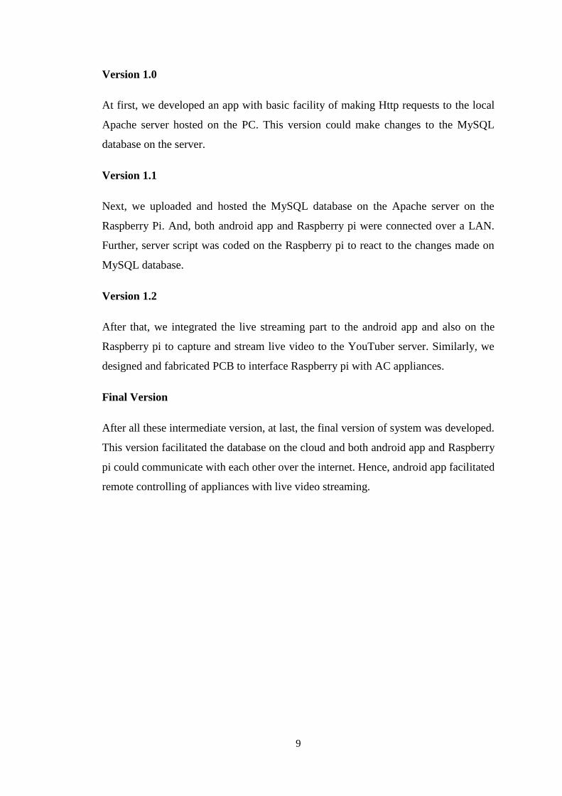
Fig 3.2: Use Case Diagram of Home Automation
In our system, user acts as a primary actor who can read status of appliances either in
‘’ON’’ state or ‘’OFF’’ state through the database. Further, the user may change the
state of appliances and control them according to the need by sending the status signals
to the database and raspberry pi gets access to the database and send control signals to
the appliances. Also watching the live stream video can be done by the user through the
YouTube stream server whenever required.
11
Class Diagram
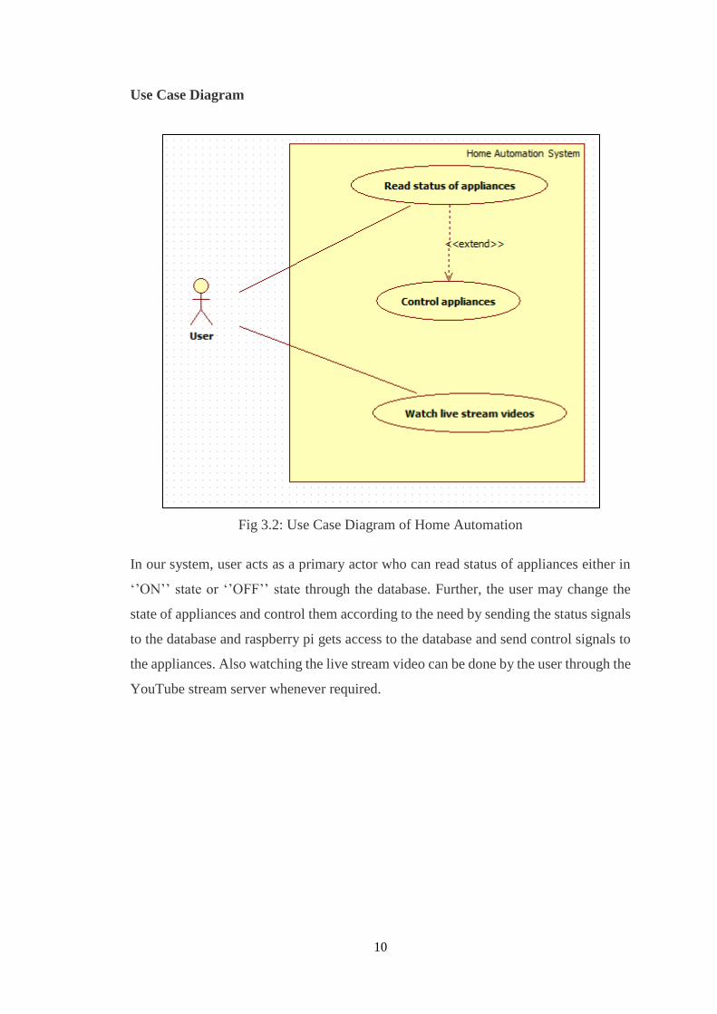
Fig 3.3: Class Diagram of Home Automation

12
Activity Diagram
The Activity diagram below shows the flow of activities or actions that occur when user
tries to interact with the system and tries to access the functionalities provided by the
system.
Fig 3.4: Activity Diagram of Home Automation System
13
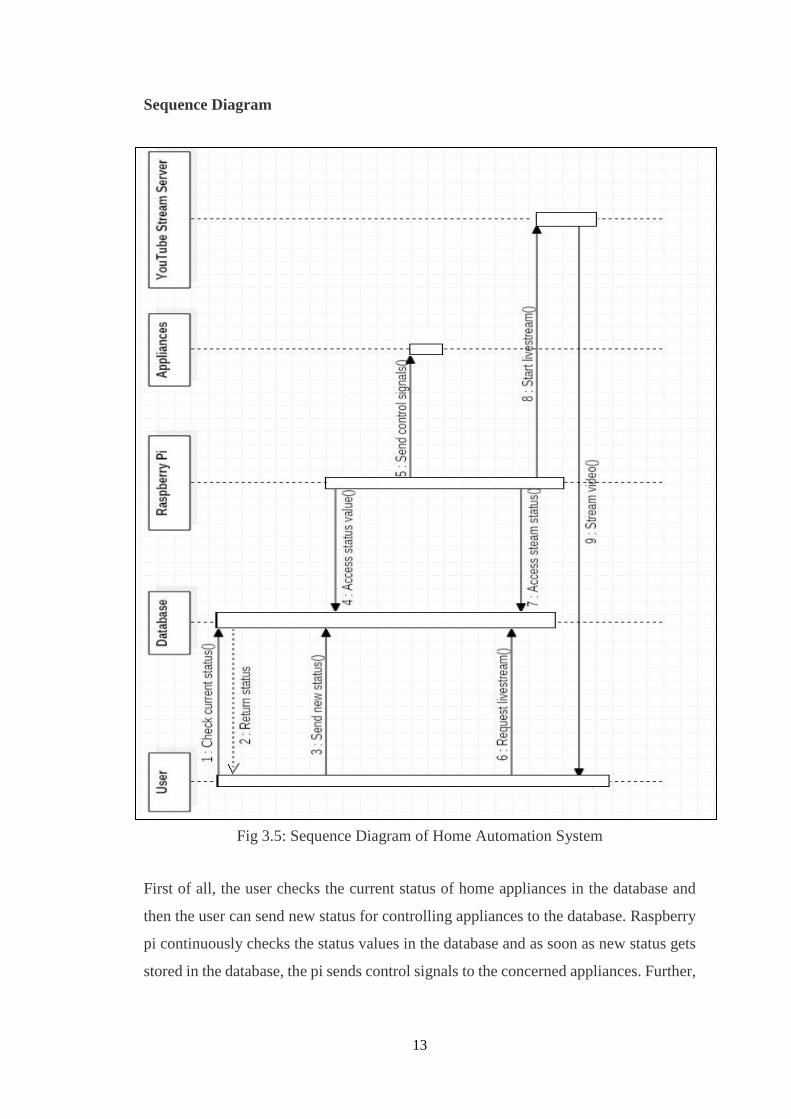
Sequence Diagram
Fig 3.5: Sequence Diagram of Home Automation System
First of all, the user checks the current status of home appliances in the database and
then the user can send new status for controlling appliances to the database. Raspberry
pi continuously checks the status values in the database and as soon as new status gets
stored in the database, the pi sends control signals to the concerned appliances. Further,
14
the user can watch live stream video through the YouTube stream server whenever
required for monitoring purposes.
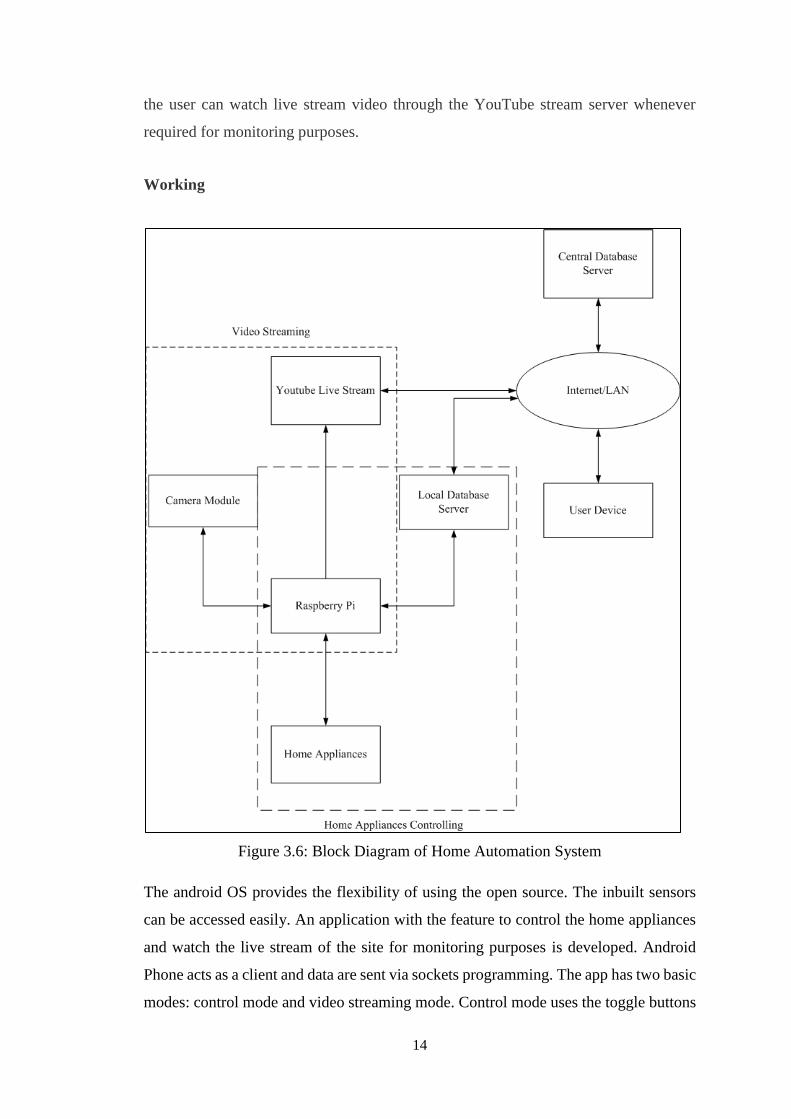
Working
Figure 3.6: Block Diagram of Home Automation System
The android OS provides the flexibility of using the open source. The inbuilt sensors
can be accessed easily. An application with the feature to control the home appliances
and watch the live stream of the site for monitoring purposes is developed. Android
Phone acts as a client and data are sent via sockets programming. The app has two basic
modes: control mode and video streaming mode. Control mode uses the toggle buttons
15
that are used to control the home appliances. The toggle button sends the status of the
switch. Video streaming mode shows the live stream of the room. The captured video
is streamed on the android application.
All the devices are connected to a common network either through LAN or Internet.
Smartphone, raspberry pi and camera are connected to the common network. Router is
used to create a common network. Raspberry pi is used to maintain the web server. The
pi collects the data, analyses it and further activates GPIO pins as necessary. The GPIO
pins of raspberry pi are connected to the relay. Relay switch are used to connect the
home appliances.
3.1 Hardware Description
The major hardware required for this project are Raspberry Pi, camera module, router,
android phone and the power strip circuit. Raspberry pi is the central part of the whole
system and pretty much acts at the core processing and control system. The camera
module is used to capture video and stream it online. Likewise, router is used to create
a LAN, which connects pi and the android phone to a common network. Similarly,
android phone is necessary to run the android app and finally power strip connects the
electrical appliances to the electronic control logic of the system.
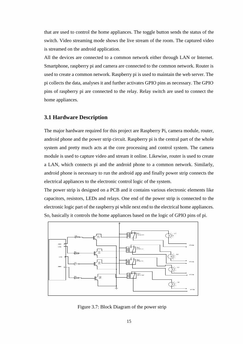
The power strip is designed on a PCB and it contains various electronic elements like
capacitors, resistors, LEDs and relays. One end of the power strip is connected to the
electronic logic part of the raspberry pi while next end to the electrical home appliances.
So, basically it controls the home appliances based on the logic of GPIO pins of pi.
Figure 3.7: Block Diagram of the power strip
16
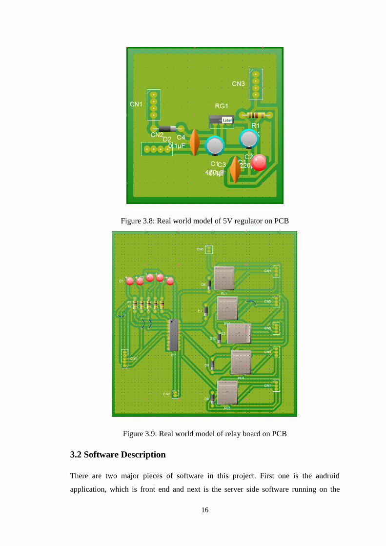
Figure 3.8: Real world model of 5V regulator on PCB
Figure 3.9: Real world model of relay board on PCB
3.2 Software Description
There are two major pieces of software in this project. First one is the android
application, which is front end and next is the server side software running on the
17
raspberry pi at the backend.
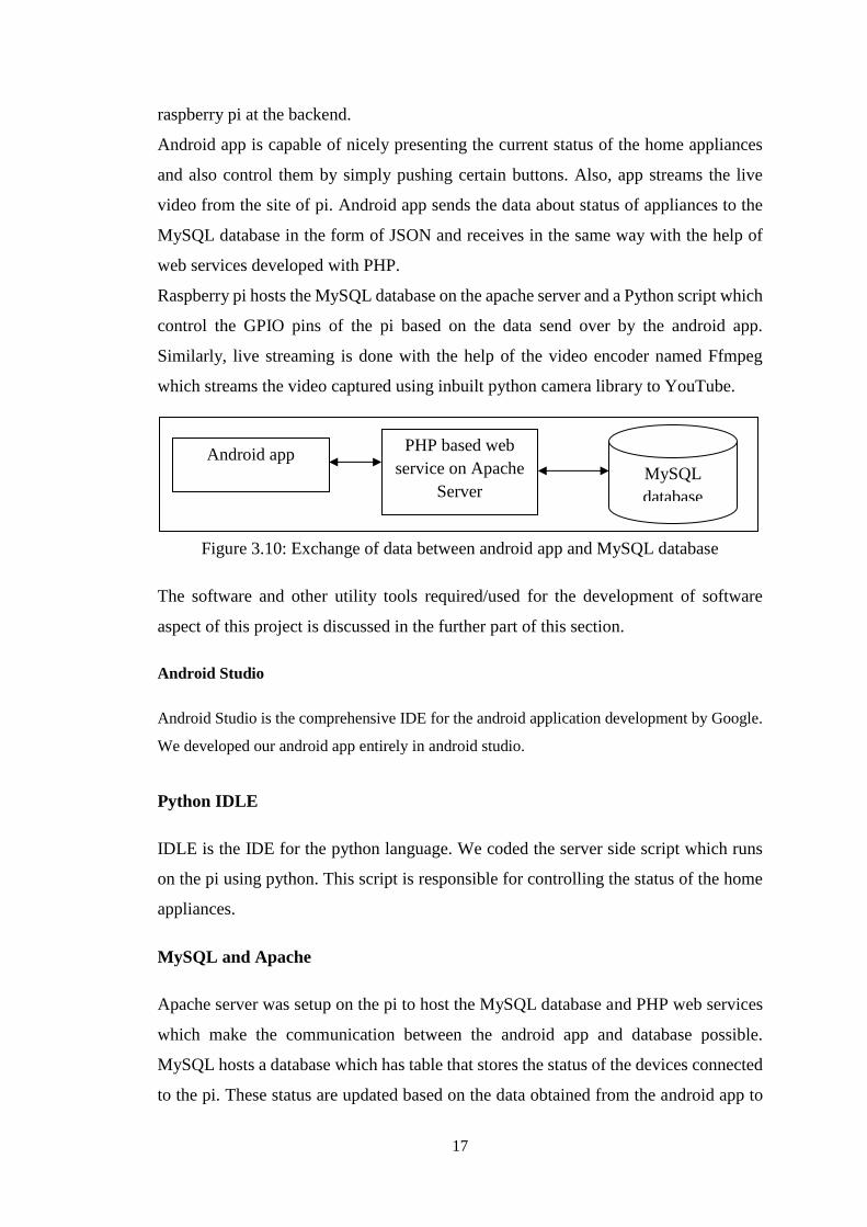
Android app is capable of nicely presenting the current status of the home appliances
and also control them by simply pushing certain buttons. Also, app streams the live
video from the site of pi. Android app sends the data about status of appliances to the
MySQL database in the form of JSON and receives in the same way with the help of
web services developed with PHP.
Raspberry pi hosts the MySQL database on the apache server and a Python script which
control the GPIO pins of the pi based on the data send over by the android app.
Similarly, live streaming is done with the help of the video encoder named Ffmpeg
which streams the video captured using inbuilt python camera library to YouTube.
Figure 3.10: Exchange of data between android app and MySQL database
The software and other utility tools required/used for the development of software
aspect of this project is discussed in the further part of this section.
Android Studio
Android Studio is the comprehensive IDE for the android application development by Google.
We developed our android app entirely in android studio.
Python IDLE
IDLE is the IDE for the python language. We coded the server side script which runs
on the pi using python. This script is responsible for controlling the status of the home
appliances.
MySQL and Apache
Apache server was setup on the pi to host the MySQL database and PHP web services
which make the communication between the android app and database possible.
MySQL hosts a database which has table that stores the status of the devices connected
to the pi. These status are updated based on the data obtained from the android app to
Android app PHP based web
service on Apache
Server MySQL
database
18
reflect the status of the home appliances.
Ffmpeg encoder
It is a video encoder which encodes the video captured by the raspberry pi camera to
convert it into a suitable format, for instance, flv, which is an acceptable video format
to be streamed by the YouTube server. We can specify a lot of parameters of the video
that we are trying to stream with this encoder for example the frame rate, video width,
height i.e. resolution and so on .
PCB Wizard
PCB Wizard is a powerful package for designing single-sided and double-sided printed
circuit boards (PCBs). It provides a comprehensive range of tools covering all the
traditional steps in PCB production, including schematic drawing, schematic capture,
component placement, automatic routing, Bill of Materials reporting and file generation
for manufacturing.
MobaXterm
It is an enhanced terminal for Windows with an X11 server, a tabbed SSH client and
several other network tools for remote computing (VNC, RDP, telnet, rlogin).
MobaXterm brings all the essential UNIX commands to Windows desktop, in a single
portable exe file which works out of the box. This software is useful for easy uploading
and downloading of files to and from raspberry pi using another machine on the
network (for instance, laptop running windows).

19
Figure 3.11: Established session of pi with Linux terminal in MobaXterm
3.3 Procedures
In this section of the report, we discuss how we achieved the aforementioned targets.
For setting up webserver on Raspberry Pi
We first installed the Raspbian OS on the raspberry pi and performed update and
upgrade to get the latest version of the OS. Then, we configured the Wi-Fi connection
on the pi. Then finally we installed apache server and MySQL server on the pi and
created a database and then a table to store the status of the devices.
For developing Server side program
We used python language to write the server side script. This script connects to the
database set up on the above step and reads the status of the devices. And based on
those data, it either turns on or off the devices.
For setting up YouTube live stream
We created a YouTube account and using live streaming option got a private key and
the server address to which the video is to be streamed. This combination is later
supplied to the Ffmpeg encoder to start the streaming.
20
For the designing of android application
We used the Android Studio IDE for the design and development of android application
which is used to communicate with the Raspberry Pi and control the home appliances.
Further, it streams the live video feed from the raspberry pi camera using YouTube API.
This process involves the layout design of the app to give the look and feel of the
android app and the coding part that does the actual task behind the scene in the
background.
For the live streaming of video
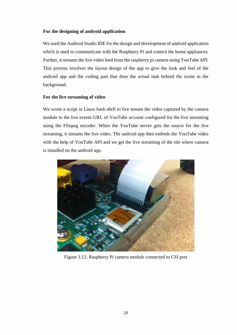
We wrote a script in Linux bash shell to live stream the video captured by the camera
module to the live events URL of YouTube account configured for the live streaming
using the Ffmpeg encoder. When the YouTube server gets the source for the live
streaming, it streams the live video. The android app then embeds the YouTube video
with the help of YouTube API and we get the live streaming of the site where camera
is installed on the android app.
Figure 3.12: Raspberry Pi camera module connected to CSI port
21
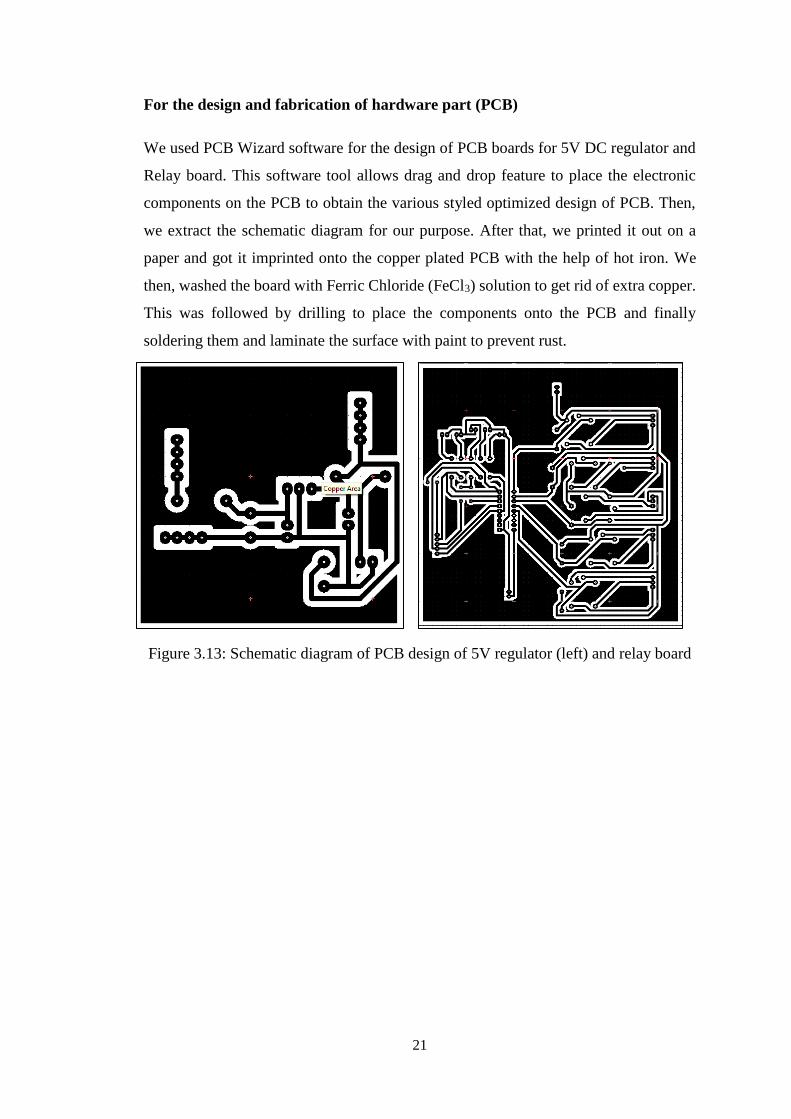
For the design and fabrication of hardware part (PCB)
We used PCB Wizard software for the design of PCB boards for 5V DC regulator and
Relay board. This software tool allows drag and drop feature to place the electronic
components on the PCB to obtain the various styled optimized design of PCB. Then,
we extract the schematic diagram for our purpose. After that, we printed it out on a
paper and got it imprinted onto the copper plated PCB with the help of hot iron. We
then, washed the board with Ferric Chloride (FeCl3) solution to get rid of extra copper.
This was followed by drilling to place the components onto the PCB and finally
soldering them and laminate the surface with paint to prevent rust.
Figure 3.13: Schematic diagram of PCB design of 5V regulator (left) and relay board
22
Chapter 4: Results and Conclusion
4.1 Result and Discussion
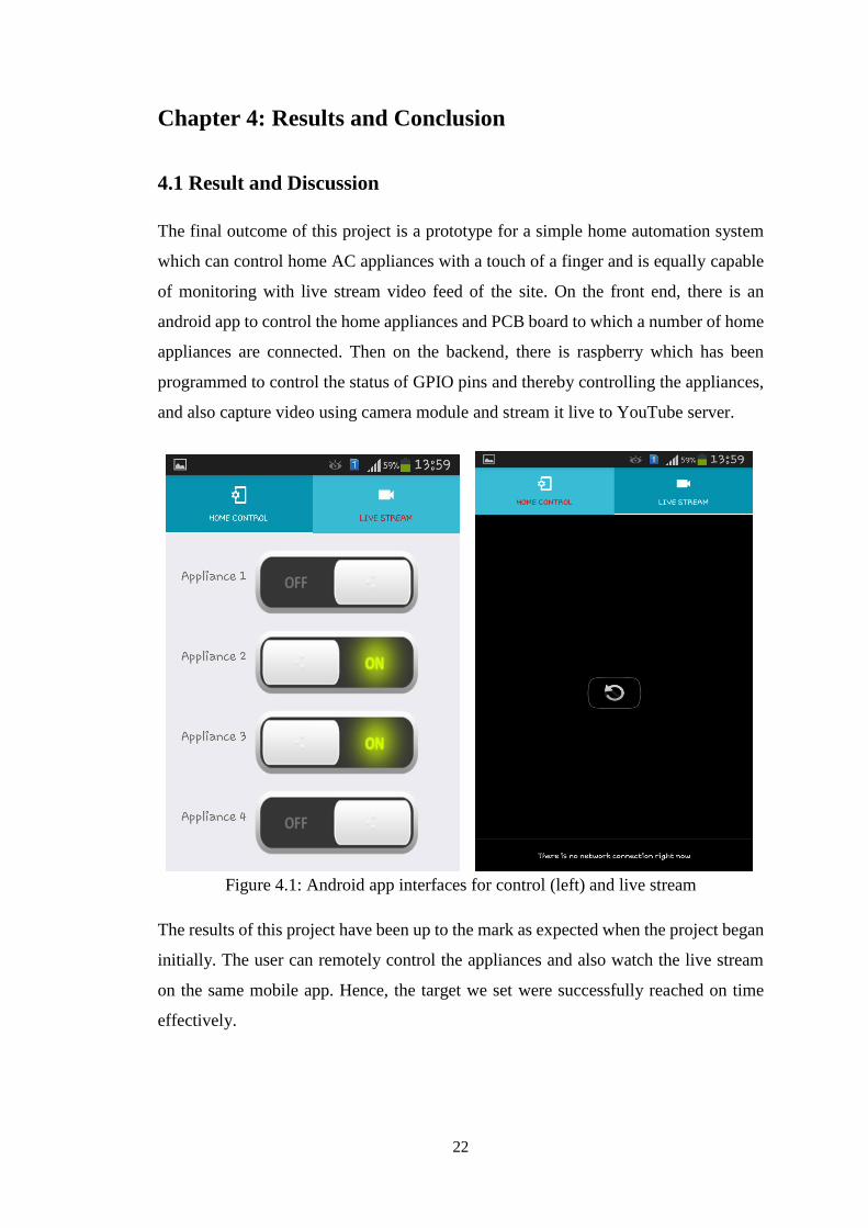
The final outcome of this project is a prototype for a simple home automation system
which can control home AC appliances with a touch of a finger and is equally capable
of monitoring with live stream video feed of the site. On the front end, there is an
android app to control the home appliances and PCB board to which a number of home
appliances are connected. Then on the backend, there is raspberry which has been
programmed to control the status of GPIO pins and thereby controlling the appliances,
and also capture video using camera module and stream it live to YouTube server.
Figure 4.1: Android app interfaces for control (left) and live stream
The results of this project have been up to the mark as expected when the project began
initially. The user can remotely control the appliances and also watch the live stream
on the same mobile app. Hence, the target we set were successfully reached on time
effectively.
23
4.2 Problems Faced
This project, by no means, completed without any problems and difficulties along the
way. Following are the problems faced during the course of completion of this project.
We had lots of difficulties getting a fully working Raspberry Pi and thus it took a
lot of our time configuring it to a fully working state.
Due to diverse nature of this project, the hardware components along the same line,
it was a difficult task to research on it and get devices that perfectly matched our
requirements on time. Moreover, some materials had to be bought on authors' part.
As it was our first take on the hardware design, for instance, the fabrication of PCB
with varieties of electronic components, we faced a lot of complexities and the
overall process was a challenging one.
On the software part, android app development and server side scripting were fairly
easy. Nonetheless, they produced some critical scenarios where it took some
handsome amount of effort.
4.3 Limitations and Future Enhancements
This project is our take on trying to create a prototype of a fully working Home
Automation System. Although every effort has been made to make it a complete and
very much closer to an ideal solution product that we wanted to achieve, there always
remain areas where further improvements are possible.
Limitations:
Since our project is just a prototype resembling a real world home automation system,
our project has following limitations:
No sensors for the real time data logging and automatic control of appliances.
Since, we utilized the free live streaming feature of YouTube, 24/7 streaming is not
possible.
Delay of around 10 sec in the live stream from the camera module to YouTube
server when it is viewed in the app.
Only limited number of appliances can be connected and thus controlled using this
system.
24
Future enhancement
By interfacing various sorts of sensors, we can program the automatic controlling of
the appliances. As for example, using temperature sensors to log the current
temperature of a room, we can control the automatic turning ON/OFF of the heater or
fan. Likewise, for the continuous streaming of video, we can set up our own video
server. This is surely to cost a lot. We could also interface Arduino to raspberry pi so
that we can increase the number of appliances that can be controlled remotely.
4.4 Budget Analysis
The following section consists of the budget analysis of the project, that is, the total
budget for the development of the project and the operational and maintenance cost that
follows after the implementation of the project.
4.4.1 Development cost
The development cost can be categorized into software and hardware development cost.
Software design and development cost:
Development cost = Rs.100 per hour
Working hours = 5 hrs per day
Total working days = 60 days (2 months)
Total working hours = 120 *5 = 300 hrs
Total cost = Rs.100*300 = Rs.30,000
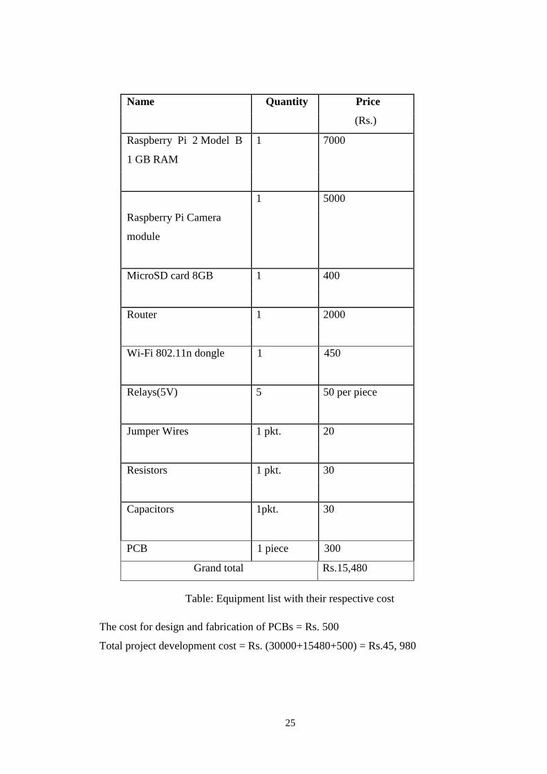
List of equipment with cost:
The cost of equipment used in this project can be summarized in the following table.
25
Name Quantity Price
(Rs.)
Raspberry Pi 2 Model B 1 7000
1 GB RAM
1 5000
Raspberry Pi Camera
module
MicroSD card 8GB 1 400
Router 1 2000
Wi-Fi 802.11n dongle
1
450
Relays(5V) 5 50 per piece
Jumper Wires 1 pkt. 20
Resistors 1 pkt. 30
Capacitors 1pkt. 30
PCB 1 piece 300
Grand total Rs.15,480
Table: Equipment list with their respective cost
The cost for design and fabrication of PCBs = Rs. 500
Total project development cost = Rs. (30000+15480+500) = Rs.45, 980
26
4.4.2 Operation and Maintenance cost:
Overall electricity cost = Rs. 100 per month (for raspberry pi and router only)
Internet Service Provider cost = Rs. 1500 per month (broadband internet)
Hardware and Software maintenance cost = Rs. 2500 per month (if needed be)
Total operational cost: Rs. (100+1500+2500) = Rs. 4,100 per month
4.5 Work Schedule
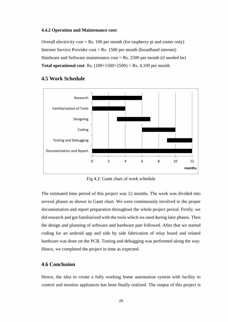
Fig 4.2: Gantt chart of work schedule
The estimated time period of this project was 12 months. The work was divided into
several phases as shown in Gantt chart. We were continuously involved in the proper
documentation and report preparation throughout the whole project period. Firstly, we
did research and got familiarized with the tools which we used during later phases. Then
the design and planning of software and hardware part followed. After that we started
coding for an android app and side by side fabrication of relay board and related
hardware was done on the PCB. Testing and debugging was performed along the way.
Hence, we completed the project in time as expected.
4.6 Conclusion
Hence, the idea to create a fully working home automation system with facility to
control and monitor appliances has been finally realized. The output of this project is
0 2 4 6 8 10 12
Documentation and Report
Testing and Debugging
Coding
Designing
Familiarization of Tools
Research
months
27
an array of home appliances that are controlled over the internet with the help of a
mobile app and the facility to stream the video live, as well. This project is a successful
outcome of continuous and tireless effort from all the project members, supervisors,
college faculty, colleagues and other helping hands.
This project has been a really great experience and opportunity to learn and to
experiment. Moreover, the authors got the chance to closely experiment and learn about
what goes into designing and developing home automation systems. We are very much
delighted that we explored this topic as our major project title and in a way, created a
version of home automation system of our own, and to be closely related with the
technology that is of a great interest of study and research today and is sure to
revolutionize the way of living of people in the days to come.
28
References
[1] N. Sriskanthan and Tan Karand. “Bluetooth Based Home Automation System”.
Journal of Microprocessors and Microsystems, Vol. 26, pp.281-289, 2002.
[2] Muhammad Izhar Ramli, Mohd Helmy Abd Wahab, Nabihah, “TOWARDS
SMART HOME: CONTROL ELECTRICAL DEVICES ONLINE”, Nornabihah
Ahmad International Conference on Science and Technology: Application in
Industry and Education (2006)
[3] E. Yavuz, B. Hasan, I. Serkan and K. Duygu. “Safe and Secure PIC Based Remote
Control Application for Intelligent Home”. International Journal of Computer
Science and Network Security, Vol. 7, No. 5, May 2007
[4] Amul Jadhav, S. Anand, Nilesh Dhangare, K.S. Wagh “Universal Mobile
Application Development (UMAD) On Home Automation” Marathwada Mitra
Mandal’s Institute of Technology, University of Pune, India Network and
Complex Systems ISSN 2224-610X (Paper) ISSN 2225-0603 (Online) Vol 2,
No.2, 2012
[5] Pratik Gadtaula, “Home Automation”, Telemark University College, Faculty of
Technology, Master’s Thesis, 2015
[6] Sabin Adhikari and co., “Android Controlled Home Automation”, Kathmandu
Engineering College, Faculty of Electronics, Major Project Report, 2015
[7] Raspberry Pi, “Resources - Teach, Learn, and Make with Raspberry Pi”, Website,
URL: https://www.raspberrypi.org/resources/ , 2016
[8] Max Ogden, “Max Ogden Blogotronz - HD live streaming cats to YouTube with
the Raspberry Pi Camera”, Website, URL:http://maxogden.com/hd-live-
streaming-cats.html, 2015
[9] Tutorials point, "Python MySQL Database Access", Website, URL:
http://www.tutorialspoint.com/python/python_databse_access.htm, 2016
29
Bibliography
1. Andrew K. Dennis, “Raspberry Pi Home Automation with Arduino”, Packt
Publishing,Birmingham B3 2PB, UK, ISBN 978-1-84969-586-2, 2013
2. Matt Richardson and co., “Getting started with Raspberry Pi”, O’Reilly Media, Inc.,
1005 Gravenstein Highway North, Sebastopol, CA 95472, ISBN: 978-1-449-34421-
4, 2013
3. Adrian McEwen and co., “Designing the Internet of Things”, Wiley & sons, Ltd,
Delhi,ISBN: 978-81-265-5686-1, 2014
4. Yury Magda, "Network and Web applications using Raspberry pi, Arduino and
Teensy", 2015
5. Raspberry Pi Guy, “Raspberry Pi Tutorials”, YouTube video tutorials, Website,
URL: https://www.youtube.com/channel/UCbgUyiaSwT1renvY9jXAbEQ, 2016
6. The Pi Hut, "How to install / use the Raspberry Pi Camera", website, URL:
https://thepihut.com/blogs/raspberry-pi-tutorials/16021420-how-to-install-use-the-
raspberry-pi-camera
7. Warren, "Installing Ffmpeg on Debian GNU/Linux Version 8.0 (Jessie)", Website,
URL: https://www.assetbank.co.uk/support/documentation/install/ffmpeg-debian-
squeeze/ffmpeg-debian-jessie/
30
APPENDIX
QUICK START GUIDE – For Raspberry Pi
(Source: https://www.raspberrypi.org/help/quick-start-guide/)
WHAT YOU WILL NEED
REQUIRED
- SD Card
We recommend an 8GB class 4 SD card – ideally preinstalled with NOOBS.
- Display and connectivity cables
Any HDMI/DVI monitor or TV should work as a display for the Pi . For best results,
use one with HDMI input, but other connections are available for older devices. Use a
standard Ethernet cable for internet access.
- Keyboard and mouse
Any standard USB keyboard and mouse will work with your Raspberry Pi.
- Power supply
Use a 5V micro USB power supply to power your Raspberry Pi. Be careful that
whatever power supply you use outputs at least 5V; insufficient power will cause your
Pi to behave in strange ways.
NOT ESSENTIAL BUT HELPFUL TO HAVE
- Internet connection
To update or download software, we recommend that you connect your Raspberry Pi
to the internet either via an Ethernet cable or a Wi-Fi adapter.
- Headphones
Headphones or earphones with a 3.5mm jack will work with your Raspberry Pi.
31
PLUGGING IN YOUR RASPBERRY PI
Before you plug anything into your Raspberry Pi, make sure that you have all the
equipment listed above to hand. Then follow these instructions:
Begin by slotting your SD card into the SD card slot on the Raspberry Pi, which
will only fit one way.
Next, plug in your USB keyboard and Mouse into the USB slots on the Raspberry
Pi.
Make sure that your monitor or TV is turned on, and that you have selected the right
input (e.g. HDMI 1, DVI, etc.)
Then connect your HDMI cable from your Raspberry Pi to your monitor or TV.
If you intend to connect your Raspberry Pi to the internet, plug in an Ethernet cable
into the Ethernet port next to the USB ports, otherwise skip this step.
When you are happy that you have plugged in all the cables and SD card required,
finally plug in the micro usb power supply. This action will turn on and boot your
Raspberry Pi.
If this is the first time your Raspberry Pi and NOOBS SD card have been used, then
you will have to select an operating system and configure it.
LOGGING INTO YOUR RASPBERRY PI
Once your Raspberry Pi has completed the boot process, a login prompt will
appear. The default login for Raspbian is username pi with the
password raspberry. Note you will not see any writing appear when you type the
password. This is a security feature in Linux.
After you have successfully logged in, you will see the command line
promptpi@raspberrypi~$
To load the graphical user interface, type startx and press Enter on your keyboard.
32
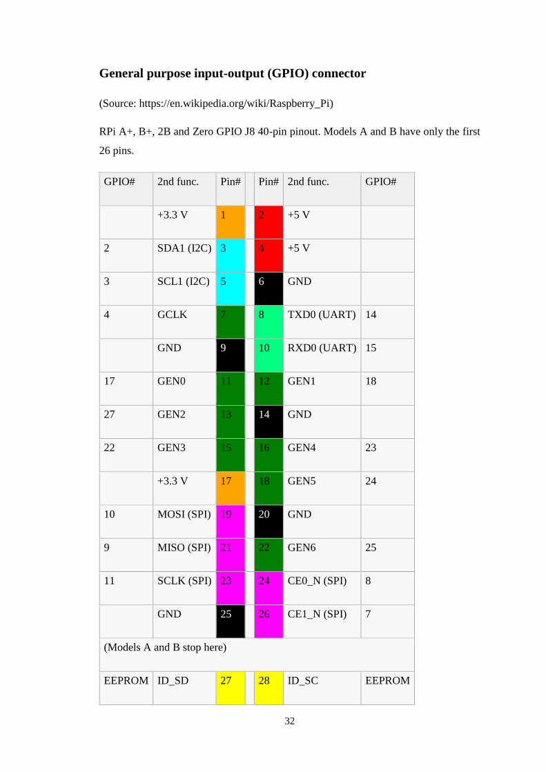
General purpose input-output (GPIO) connector
(Source: https://en.wikipedia.org/wiki/Raspberry_Pi)
RPi A+, B+, 2B and Zero GPIO J8 40-pin pinout. Models A and B have only the first
26 pins.
GPIO# 2nd func. Pin# Pin# 2nd func. GPIO#
+3.3 V 1 2 +5 V
2 SDA1 (I2C) 3 4 +5 V
3 SCL1 (I2C) 5 6 GND
4 GCLK 7 8 TXD0 (UART) 14
GND 9 10 RXD0 (UART) 15
17 GEN0 11 12 GEN1 18
27 GEN2 13 14 GND
22 GEN3 15 16 GEN4 23
+3.3 V 17 18 GEN5 24
10 MOSI (SPI) 19 20 GND
9 MISO (SPI) 21 22 GEN6 25
11 SCLK (SPI) 23 24 CE0_N (SPI) 8
GND 25 26 CE1_N (SPI) 7
(Models A and B stop here)
EEPROM ID_SD 27 28 ID_SC EEPROM
33
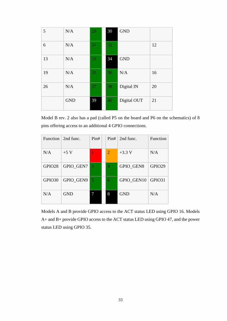
5 N/A 29 30 GND
6 N/A 31 32 12
13 N/A 33 34 GND
19 N/A 35 36 N/A 16
26 N/A 37 38 Digital IN 20
GND 39 40 Digital OUT 21
Model B rev. 2 also has a pad (called P5 on the board and P6 on the schematics) of 8
pins offering access to an additional 4 GPIO connections.
Function 2nd func. Pin# Pin# 2nd func. Function
N/A +5 V 1 2 +3.3 V N/A
GPIO28 GPIO_GEN7 3 4 GPIO_GEN8 GPIO29
GPIO30 GPIO_GEN9 5 6 GPIO_GEN10 GPIO31
N/A GND 7 8 GND N/A
Models A and B provide GPIO access to the ACT status LED using GPIO 16. Models
A+ and B+ provide GPIO access to the ACT status LED using GPIO 47, and the power
status LED using GPIO 35.