Embed Size (px)
DESCRIPTION
solucionario de mecanica de fluidos del capitulo 3
Citation preview
Chapter 3 Pressure and Fluid Statics
PROPRIETARY MATERIAL. © 2006 The McGraw-Hill Companies, Inc. Limited distribution permitted only to teachers and educators for course preparation. If you are a student using this Manual, you are using it without permission.
3-1
Solutions Manual for Fluid Mechanics: Fundamentals and Applications
by Çengel & Cimbala
CHAPTER 3 PRESSURE AND FLUID STATICS
PROPRIETARY AND CONFIDENTIAL This Manual is the proprietary property of The McGraw-Hill Companies, Inc. (“McGraw-Hill”) and protected by copyright and other state and federal laws. By opening and using this Manual the user agrees to the following restrictions, and if the recipient does not agree to these restrictions, the Manual should be promptly returned unopened to McGraw-Hill: This Manual is being provided only to authorized professors and instructors for use in preparing for the classes using the affiliated textbook. No other use or distribution of this Manual is permitted. This Manual may not be sold and may not be distributed to or used by any student or other third party. No part of this Manual may be reproduced, displayed or distributed in any form or by any means, electronic or otherwise, without the prior written permission of McGraw-Hill.
Chapter 3 Pressure and Fluid Statics
PROPRIETARY MATERIAL. © 2006 The McGraw-Hill Companies, Inc. Limited distribution permitted only to teachers and educators for course preparation. If you are a student using this Manual, you are using it without permission.
3-2
Pressure, Manometer, and Barometer 3-1C Solution We are to discuss the difference between gage pressure and absolute pressure. Analysis The pressure relative to the atmospheric pressure is called the gage pressure, and the pressure relative to an absolute vacuum is called absolute pressure. Discussion Most pressure gages (like your bicycle tire gage) read relative to atmospheric pressure, and therefore read the gage pressure.
3-2C Solution We are to explain nose bleeding and shortness of breath at high elevation. Analysis Atmospheric air pressure which is the external pressure exerted on the skin decreases with increasing elevation. Therefore, the pressure is lower at higher elevations. As a result, the difference between the blood pressure in the veins and the air pressure outside increases. This pressure imbalance may cause some thin-walled veins such as the ones in the nose to burst, causing bleeding. The shortness of breath is caused by the lower air density at higher elevations, and thus lower amount of oxygen per unit volume. Discussion People who climb high mountains like Mt. Everest suffer other physical problems due to the low pressure.
3-3C Solution We are to examine a claim about absolute pressure. Analysis No, the absolute pressure in a liquid of constant density does not double when the depth is doubled. It is the gage pressure that doubles when the depth is doubled. Discussion This is analogous to temperature scales – when performing analysis using something like the ideal gas law, you must use absolute temperature (K), not relative temperature (oC), or you will run into the same kind of problem.
3-4C Solution We are to compare the pressure on the surfaces of a cube. Analysis Since pressure increases with depth, the pressure on the bottom face of the cube is higher than that on the top. The pressure varies linearly along the side faces. However, if the lengths of the sides of the tiny cube suspended in water by a string are very small, the magnitudes of the pressures on all sides of the cube are nearly the same. Discussion In the limit of an “infinitesimal cube”, we have a fluid particle, with pressure P defined at a “point”.
3-5C Solution We are to define Pascal’s law and give an example. Analysis Pascal’s law states that the pressure applied to a confined fluid increases the pressure throughout by the same amount. This is a consequence of the pressure in a fluid remaining constant in the horizontal direction. An example of Pascal’s principle is the operation of the hydraulic car jack. Discussion The above discussion applies to fluids at rest (hydrostatics). When fluids are in motion, Pascal’s principle does not necessarily apply. However, as we shall see in later chapters, the differential equations of incompressible fluid flow contain only pressure gradients, and thus an increase in pressure in the whole system does not affect fluid motion.
Chapter 3 Pressure and Fluid Statics
PROPRIETARY MATERIAL. © 2006 The McGraw-Hill Companies, Inc. Limited distribution permitted only to teachers and educators for course preparation. If you are a student using this Manual, you are using it without permission.
3-3
3-6C Solution We are to compare the volume and mass flow rates of two fans at different elevations. Analysis The density of air at sea level is higher than the density of air on top of a high mountain. Therefore, the volume flow rates of the two fans running at identical speeds will be the same, but the mass flow rate of the fan at sea level will be higher. Discussion In reality, the fan blades on the high mountain would experience less frictional drag, and hence the fan motor would not have as much resistance – the rotational speed of the fan on the mountain would be slightly higher than that at sea level.
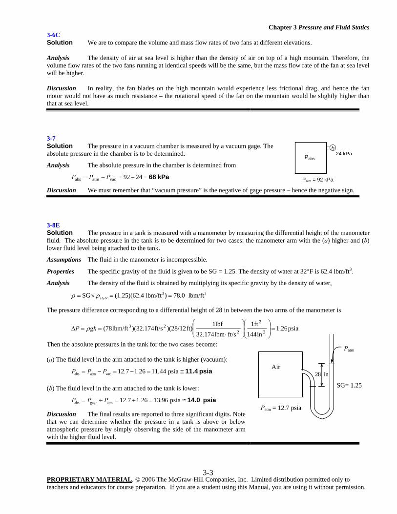
3-7 Solution The pressure in a vacuum chamber is measured by a vacuum gage. The absolute pressure in the chamber is to be determined.
Analysis The absolute pressure in the chamber is determined from
kPa 68=−=−= 2492vacatmabs PPP
Discussion We must remember that “vacuum pressure” is the negative of gage pressure – hence the negative sign.
3-8E Solution The pressure in a tank is measured with a manometer by measuring the differential height of the manometer fluid. The absolute pressure in the tank is to be determined for two cases: the manometer arm with the (a) higher and (b) lower fluid level being attached to the tank.
Assumptions The fluid in the manometer is incompressible.
Properties The specific gravity of the fluid is given to be SG = 1.25. The density of water at 32°F is 62.4 lbm/ft3.
Analysis The density of the fluid is obtained by multiplying its specific gravity by the density of water,
2
3 3SG (1.25)(62.4 lbm/ft ) 78 0 lbm/ftH O .ρ ρ= × = =
The pressure difference corresponding to a differential height of 28 in between the two arms of the manometer is
psia26.1in144
ft1ft/slbm32.174
lbf1ft))(28/12ft/s)(32.174lbm/ft(78
2
2
223 =⎟
⎟⎠
⎞⎜⎜⎝
⎛⎟⎟⎠
⎞⎜⎜⎝
⎛
⋅==Δ ghP ρ
Then the absolute pressures in the tank for the two cases become: (a) The fluid level in the arm attached to the tank is higher (vacuum):
abs atm vac 12 7 1 26 11 44 psiaP P P . . .= − = − = ≅ 11.4 psia (b) The fluid level in the arm attached to the tank is lower:
abs gage atm 12 7 1 26 13 96 psiaP P P . . .= + = + = ≅ 14.0 psia
Discussion The final results are reported to three significant digits. Note that we can determine whether the pressure in a tank is above or below atmospheric pressure by simply observing the side of the manometer arm with the higher fluid level.
Pabs
Patm = 92 kPa
24 kPa
Air
SG= 1.25
Patm = 12.7 psia
28 in
Patm
Chapter 3 Pressure and Fluid Statics
PROPRIETARY MATERIAL. © 2006 The McGraw-Hill Companies, Inc. Limited distribution permitted only to teachers and educators for course preparation. If you are a student using this Manual, you are using it without permission.
3-4
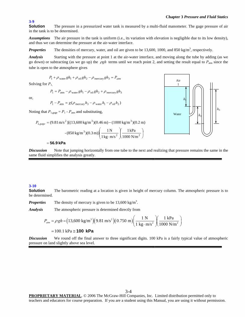
3-9 Solution The pressure in a pressurized water tank is measured by a multi-fluid manometer. The gage pressure of air in the tank is to be determined.
Assumptions The air pressure in the tank is uniform (i.e., its variation with elevation is negligible due to its low density), and thus we can determine the pressure at the air-water interface.
Properties The densities of mercury, water, and oil are given to be 13,600, 1000, and 850 kg/m3, respectively.
Analysis Starting with the pressure at point 1 at the air-water interface, and moving along the tube by adding (as we go down) or subtracting (as we go up) the ghρ terms until we reach point 2, and setting the result equal to Patm since the tube is open to the atmosphere gives
atmPghghghP =−++ 3mercury2oil1water1 ρρρ
Solving for P1,
3mercury2oil1wateratm1 ghghghPP ρρρ +−−=
or, )( 2oil1water3mercuryatm1 hhhgPP ρρρ −−=−
Noting that P1,gage = P1 - Patm and substituting,
kPa 56.9=
⎟⎠
⎞⎜⎝
⎛⎟⎟⎠
⎞⎜⎜⎝
⎛
⋅
−=
223
332,1
N/m 1000kPa 1
m/skg 1N 1m)] 3.0)(kg/m (850-
m) 2.0)(kg/m (1000m) 46.0)(kg/m )[(13,600m/s (9.81gageP
Discussion Note that jumping horizontally from one tube to the next and realizing that pressure remains the same in the same fluid simplifies the analysis greatly.
3-10 Solution The barometric reading at a location is given in height of mercury column. The atmospheric pressure is to be determined.
Properties The density of mercury is given to be 13,600 kg/m3.
Analysis The atmospheric pressure is determined directly from
( )( )( )3 22 2
1 N 1 kPa13,600 kg/m 9 81 m/s 0 750 m1 kg m/s 1000 N/m
100 1 kPa
atmP gh . .
.
ρ⎛ ⎞⎛ ⎞= = ⎜ ⎟⎜ ⎟⋅ ⎝ ⎠⎝ ⎠
= ≅ 100 kPa
Discussion We round off the final answer to three significant digits. 100 kPa is a fairly typical value of atmospheric pressure on land slightly above sea level.
Water
h1
Air 1
h3
h2
Chapter 3 Pressure and Fluid Statics
PROPRIETARY MATERIAL. © 2006 The McGraw-Hill Companies, Inc. Limited distribution permitted only to teachers and educators for course preparation. If you are a student using this Manual, you are using it without permission.
3-5
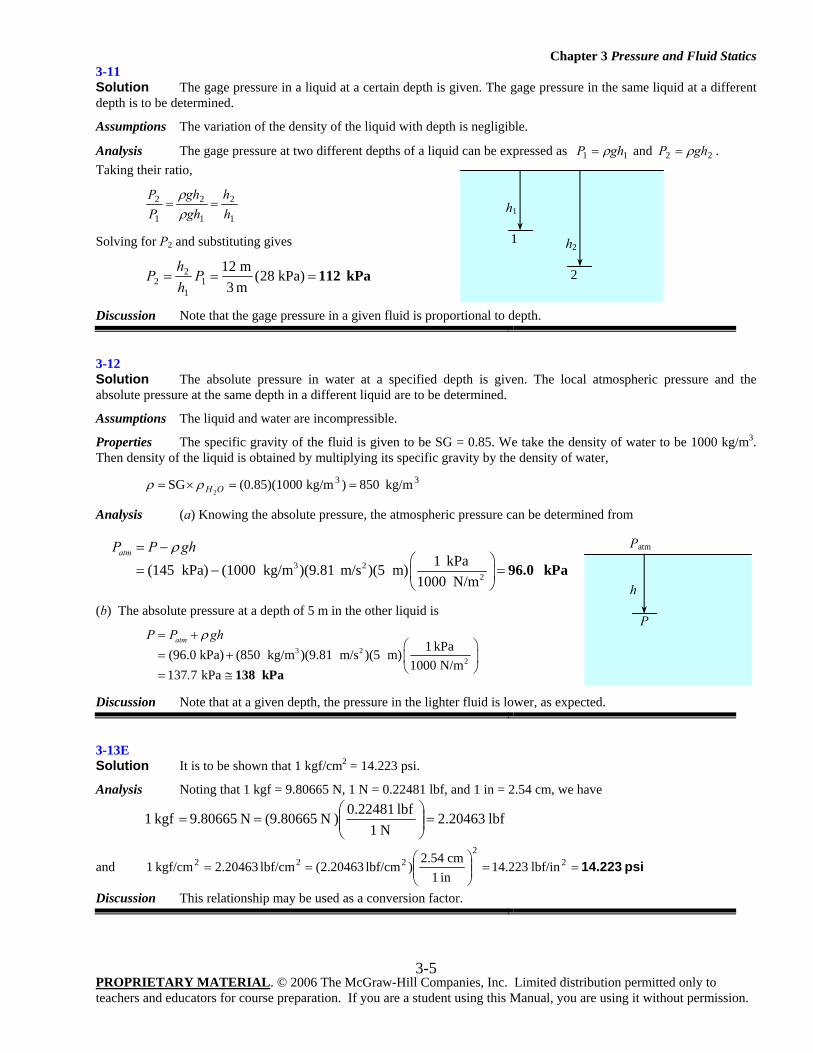
3-11 Solution The gage pressure in a liquid at a certain depth is given. The gage pressure in the same liquid at a different depth is to be determined.
Assumptions The variation of the density of the liquid with depth is negligible.
Analysis The gage pressure at two different depths of a liquid can be expressed as 11 ghP ρ= and 22 ghP ρ= . Taking their ratio,
1
2
1
2
1
2
hh
ghgh
PP
==ρρ
Solving for P2 and substituting gives
kPa 112=== kPa) 28(m 3m 12
11
22 P
hh
P
Discussion Note that the gage pressure in a given fluid is proportional to depth.
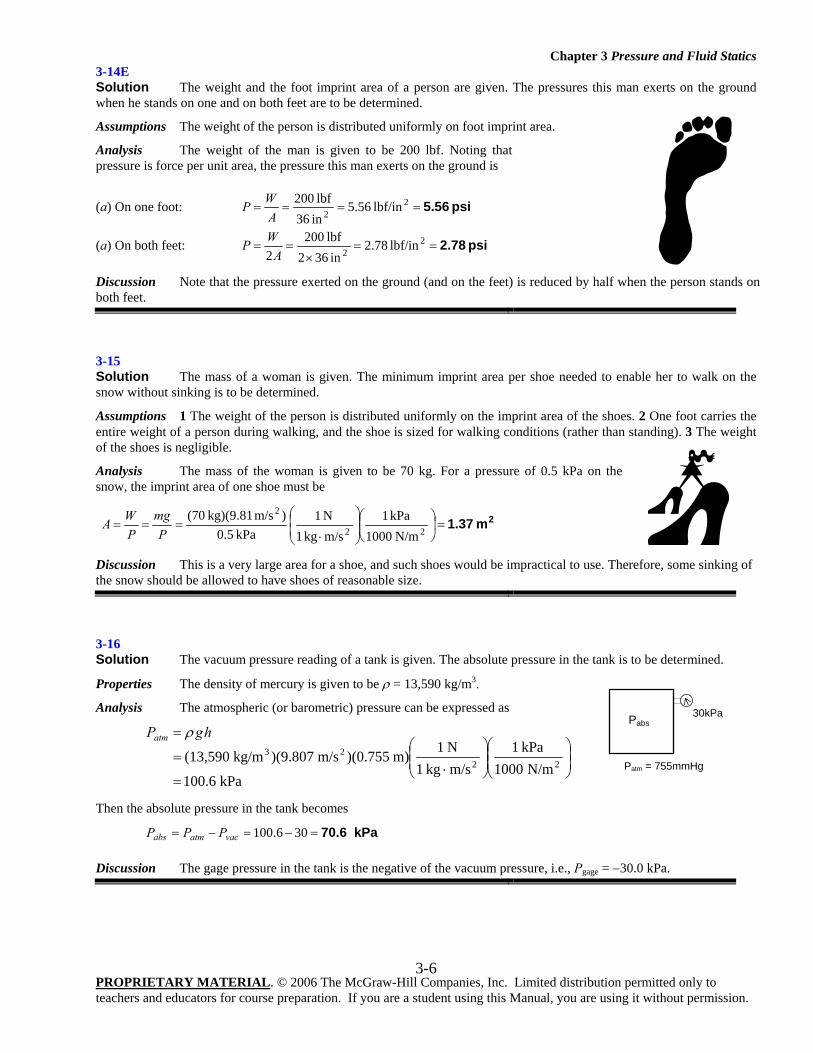
3-12 Solution The absolute pressure in water at a specified depth is given. The local atmospheric pressure and the absolute pressure at the same depth in a different liquid are to be determined.
Assumptions The liquid and water are incompressible.
Properties The specific gravity of the fluid is given to be SG = 0.85. We take the density of water to be 1000 kg/m3. Then density of the liquid is obtained by multiplying its specific gravity by the density of water,
33 kg/m850)kg/m 0(0.85)(100SG2
==×= OHρρ
Analysis (a) Knowing the absolute pressure, the atmospheric pressure can be determined from
3 22
1 kPa(145 kPa) (1000 kg/m )(9.81 m/s )(5 m)1000 N/m
atmP P ghρ= −⎛ ⎞
= − =⎜ ⎟⎝ ⎠
96.0 kPa
(b) The absolute pressure at a depth of 5 m in the other liquid is
3 22
1 kPa(96.0 kPa) (850 kg/m )(9.81 m/s )(5 m)1000 N/m
137 7 kPa
atmP P gh
.
ρ= +⎛ ⎞
= + ⎜ ⎟⎝ ⎠= ≅ 138 kPa
Discussion Note that at a given depth, the pressure in the lighter fluid is lower, as expected.
3-13E Solution It is to be shown that 1 kgf/cm2 = 14.223 psi.
Analysis Noting that 1 kgf = 9.80665 N, 1 N = 0.22481 lbf, and 1 in = 2.54 cm, we have
lbf 20463.2N 1
lbf 0.22481) N 9.80665( N 9.80665 kgf 1 =⎟⎟⎠
⎞⎜⎜⎝
⎛==
and psi 14.223==⎟⎟⎠
⎞⎜⎜⎝
⎛== 2
2222 lbf/in 223.14
in 1cm 2.54
)lbf/cm 20463.2( lbf/cm 20463.2kgf/cm 1
Discussion This relationship may be used as a conversion factor.
h1 1 h2
2
Patm h
P
Chapter 3 Pressure and Fluid Statics
PROPRIETARY MATERIAL. © 2006 The McGraw-Hill Companies, Inc. Limited distribution permitted only to teachers and educators for course preparation. If you are a student using this Manual, you are using it without permission.
3-6
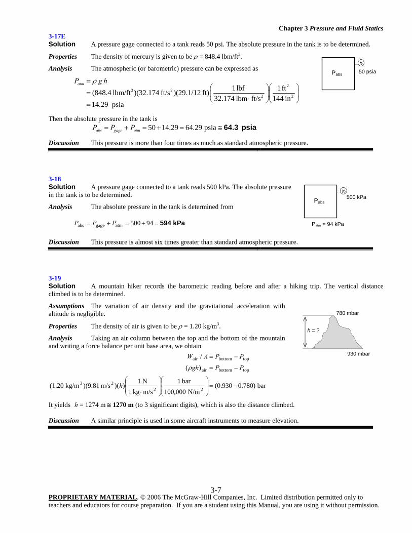
3-14E Solution The weight and the foot imprint area of a person are given. The pressures this man exerts on the ground when he stands on one and on both feet are to be determined.
Assumptions The weight of the person is distributed uniformly on foot imprint area.
Analysis The weight of the man is given to be 200 lbf. Noting that pressure is force per unit area, the pressure this man exerts on the ground is
(a) On one foot: psi 5.56==== lbf/in 56.5in 36lbf 200 2
2AWP
(a) On both feet: psi 2.78==×
== lbf/in 78.2in 362
lbf 2002
22A
WP
Discussion Note that the pressure exerted on the ground (and on the feet) is reduced by half when the person stands on both feet.
3-15 Solution The mass of a woman is given. The minimum imprint area per shoe needed to enable her to walk on the snow without sinking is to be determined.
Assumptions 1 The weight of the person is distributed uniformly on the imprint area of the shoes. 2 One foot carries the entire weight of a person during walking, and the shoe is sized for walking conditions (rather than standing). 3 The weight of the shoes is negligible.
Analysis The mass of the woman is given to be 70 kg. For a pressure of 0.5 kPa on the snow, the imprint area of one shoe must be
2m 1.37=⎟⎠
⎞⎜⎝
⎛⎟⎟⎠
⎞⎜⎜⎝
⎛
⋅===
22
2
N/m 1000kPa 1
m/skg 1N 1
kPa 0.5)m/s kg)(9.81 (70
Pmg
PWA
Discussion This is a very large area for a shoe, and such shoes would be impractical to use. Therefore, some sinking of the snow should be allowed to have shoes of reasonable size.
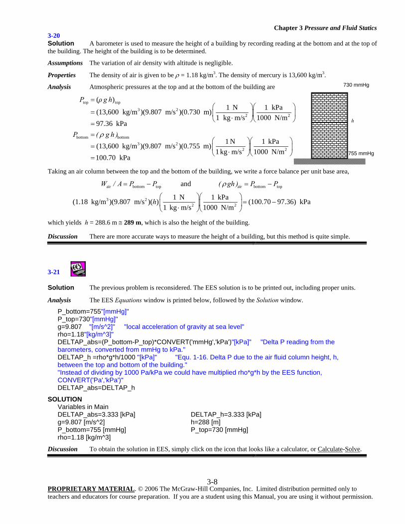
3-16 Solution The vacuum pressure reading of a tank is given. The absolute pressure in the tank is to be determined.
Properties The density of mercury is given to be ρ = 13,590 kg/m3.
Analysis The atmospheric (or barometric) pressure can be expressed as
kPa 100.6N/m 1000
kPa 1m/skg 1N 1m) )(0.755m/s )(9.807kg/m (13,590 22
23
=⎟⎟⎠
⎞⎜⎜⎝
⎛⎟⎟⎠
⎞⎜⎜⎝
⎛
⋅=
= hgPatm ρ
Then the absolute pressure in the tank becomes
kPa 70.6=−=−= 30100.6vacatmabs PPP Discussion The gage pressure in the tank is the negative of the vacuum pressure, i.e., Pgage = −30.0 kPa.
Pabs
Patm = 755mmHg
30kPa
Chapter 3 Pressure and Fluid Statics
PROPRIETARY MATERIAL. © 2006 The McGraw-Hill Companies, Inc. Limited distribution permitted only to teachers and educators for course preparation. If you are a student using this Manual, you are using it without permission.
3-7
3-17E Solution A pressure gage connected to a tank reads 50 psi. The absolute pressure in the tank is to be determined.
Properties The density of mercury is given to be ρ = 848.4 lbm/ft3.
Analysis The atmospheric (or barometric) pressure can be expressed as
2
3 22 2
1 lbf 1ft(848.4 lbm/ft )(32.174 ft/s )(29.1/12 ft)32.174 lbm ft/s 144 in
14.29 psia
atmP g hρ=⎛ ⎞⎛ ⎞
= ⎜ ⎟⎜ ⎟⋅⎝ ⎠⎝ ⎠=
Then the absolute pressure in the tank is 50 14.29 64 29 psiaabs gage atmP P P .= + = + = ≅ 64.3 psia
Discussion This pressure is more than four times as much as standard atmospheric pressure.
3-18 Solution A pressure gage connected to a tank reads 500 kPa. The absolute pressure in the tank is to be determined.
Analysis The absolute pressure in the tank is determined from
kPa 594=+=+= 94500atmgageabs PPP
Discussion This pressure is almost six times greater than standard atmospheric pressure.
3-19 Solution A mountain hiker records the barometric reading before and after a hiking trip. The vertical distance climbed is to be determined.
Assumptions The variation of air density and the gravitational acceleration with altitude is negligible.
Properties The density of air is given to be ρ = 1.20 kg/m3.
Analysis Taking an air column between the top and the bottom of the mountain and writing a force balance per unit base area, we obtain
bar 0.780)(0.930N/m 100,000
bar 1m/skg 1N 1
))(m/s )(9.81kg/m (1.20
)(
/
2223
topbottomair
topbottomair
−=⎟⎟⎠
⎞⎜⎜⎝
⎛⎟⎟⎠
⎞⎜⎜⎝
⎛
⋅
−=
−=
h
PPgh
PPAW
ρ
It yields h = 1274 m ≅ 1270 m (to 3 significant digits), which is also the distance climbed. Discussion A similar principle is used in some aircraft instruments to measure elevation.
h = ?
780 mbar
930 mbar
Pabs 50 psia
Pabs
Patm = 94 kPa
500 kPa
Chapter 3 Pressure and Fluid Statics
PROPRIETARY MATERIAL. © 2006 The McGraw-Hill Companies, Inc. Limited distribution permitted only to teachers and educators for course preparation. If you are a student using this Manual, you are using it without permission.
3-8
3-20 Solution A barometer is used to measure the height of a building by recording reading at the bottom and at the top of the building. The height of the building is to be determined.
Assumptions The variation of air density with altitude is negligible.
Properties The density of air is given to be ρ = 1.18 kg/m3. The density of mercury is 13,600 kg/m3.
Analysis Atmospheric pressures at the top and at the bottom of the building are
top top
3 22 2
bottom bottom3 2
2 2
( )1 N 1 kPa(13,600 kg/m )(9.807 m/s )(0.730 m)
1 kg m/s 1000 N/m97.36 kPa
1 N 1 kPa(13,600 kg/m )(9.807 m/s )(0.755 m)1 kg m/s 1000 N/m
100.70 kPa
P ρ g h
P ( g h )ρ
=⎛ ⎞⎛ ⎞
= ⎜ ⎟⎜ ⎟⋅⎝ ⎠⎝ ⎠==
⎛ ⎞⎛ ⎞= ⎜ ⎟⎜ ⎟⋅⎝ ⎠⎝ ⎠=
Taking an air column between the top and the bottom of the building, we write a force balance per unit base area,
air bottom top air bottom top
3 22 2
and
1 N 1 kPa(1.18 kg/m )(9.807 m/s )( ) (100.70 97.36) kPa1 kg m/s 1000 N/m
W / A P P ( gh ) P P
h
ρ= − = −
⎛ ⎞⎛ ⎞= −⎜ ⎟⎜ ⎟⋅⎝ ⎠⎝ ⎠
which yields h = 288.6 m ≅ 289 m, which is also the height of the building. Discussion There are more accurate ways to measure the height of a building, but this method is quite simple.
3-21
Solution The previous problem is reconsidered. The EES solution is to be printed out, including proper units.
Analysis The EES Equations window is printed below, followed by the Solution window.
P_bottom=755"[mmHg]" P_top=730"[mmHg]" g=9.807 "[m/s^2]" "local acceleration of gravity at sea level" rho=1.18"[kg/m^3]" DELTAP_abs=(P_bottom-P_top)*CONVERT('mmHg','kPa')"[kPa]" "Delta P reading from the barometers, converted from mmHg to kPa." DELTAP_h =rho*g*h/1000 "[kPa]" "Equ. 1-16. Delta P due to the air fluid column height, h, between the top and bottom of the building." "Instead of dividing by 1000 Pa/kPa we could have multiplied rho*g*h by the EES function, CONVERT('Pa','kPa')" DELTAP_abs=DELTAP_h
SOLUTION Variables in Main DELTAP_abs=3.333 [kPa] DELTAP_h=3.333 [kPa] g=9.807 [m/s^2] h=288 [m] P_bottom=755 [mmHg] P_top=730 [mmHg] rho=1.18 [kg/m^3]
Discussion To obtain the solution in EES, simply click on the icon that looks like a calculator, or Calculate-Solve.
730 mmHg
755 mmHg
h
Chapter 3 Pressure and Fluid Statics
PROPRIETARY MATERIAL. © 2006 The McGraw-Hill Companies, Inc. Limited distribution permitted only to teachers and educators for course preparation. If you are a student using this Manual, you are using it without permission.
3-9
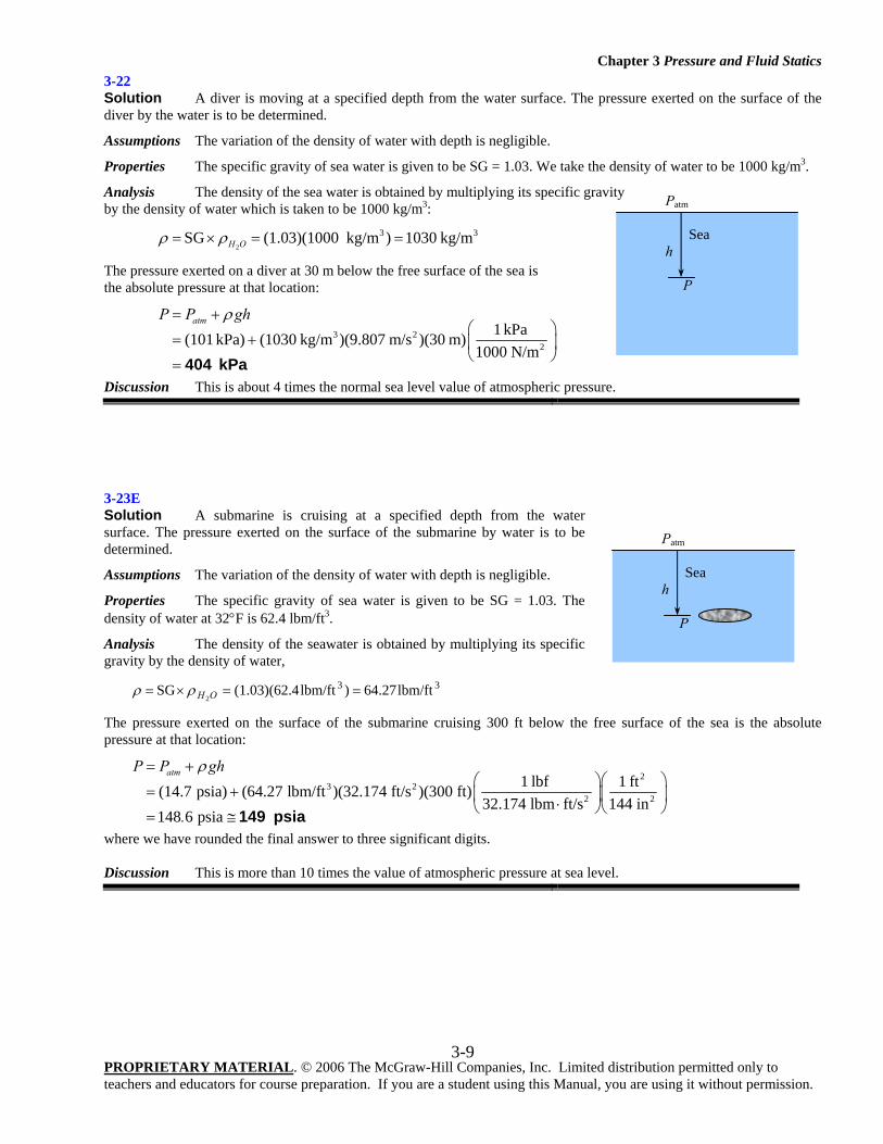
3-22 Solution A diver is moving at a specified depth from the water surface. The pressure exerted on the surface of the diver by the water is to be determined.
Assumptions The variation of the density of water with depth is negligible.
Properties The specific gravity of sea water is given to be SG = 1.03. We take the density of water to be 1000 kg/m3.
Analysis The density of the sea water is obtained by multiplying its specific gravity by the density of water which is taken to be 1000 kg/m3:
2
3 3SG (1.03)(1000 kg/m ) 1030 kg/mH Oρ ρ= × = =
The pressure exerted on a diver at 30 m below the free surface of the sea is the absolute pressure at that location:
3 22
1 kPa(101 kPa) (1030 kg/m )(9.807 m/s )(30 m)1000 N/m
atmP P ghρ= +⎛ ⎞
= + ⎜ ⎟⎝ ⎠= 404 kPa
Discussion This is about 4 times the normal sea level value of atmospheric pressure.
3-23E Solution A submarine is cruising at a specified depth from the water surface. The pressure exerted on the surface of the submarine by water is to be determined.
Assumptions The variation of the density of water with depth is negligible.
Properties The specific gravity of sea water is given to be SG = 1.03. The density of water at 32°F is 62.4 lbm/ft3.
Analysis The density of the seawater is obtained by multiplying its specific gravity by the density of water,
33 lbm/ft64.27)lbm/ft4(1.03)(62.SG2
==×= OHρρ
The pressure exerted on the surface of the submarine cruising 300 ft below the free surface of the sea is the absolute pressure at that location:
2
3 22 2
1 lbf 1 ft(14.7 psia) (64.27 lbm/ft )(32.174 ft/s )(300 ft)32.174 lbm ft/s 144 in
148 6 psia
atmP P gh
.
ρ= +⎛ ⎞⎛ ⎞
= + ⎜ ⎟⎜ ⎟⋅⎝ ⎠⎝ ⎠= ≅ 149 psia
where we have rounded the final answer to three significant digits. Discussion This is more than 10 times the value of atmospheric pressure at sea level.
Patm
Sea h
P
Patm
Sea h
P
Chapter 3 Pressure and Fluid Statics
PROPRIETARY MATERIAL. © 2006 The McGraw-Hill Companies, Inc. Limited distribution permitted only to teachers and educators for course preparation. If you are a student using this Manual, you are using it without permission.
3-10
3-24 Solution A gas contained in a vertical piston-cylinder device is pressurized by a spring and by the weight of the piston. The pressure of the gas is to be determined.
Analysis Drawing the free body diagram of the piston and balancing the vertical forces yields
PA P A W Fatm spring= + + Thus,
springatm
2
4 2 2
(4 kg)(9.807 m/s ) 60 N 1 kPa(95 kPa) 123 4 kPa35 10 m 1000 N/m
mg FP P
A
.−
+= +
⎛ ⎞+= + = ≅⎜ ⎟× ⎝ ⎠
123 kPa
Discussion This setup represents a crude but functional way to control the pressure in a tank.
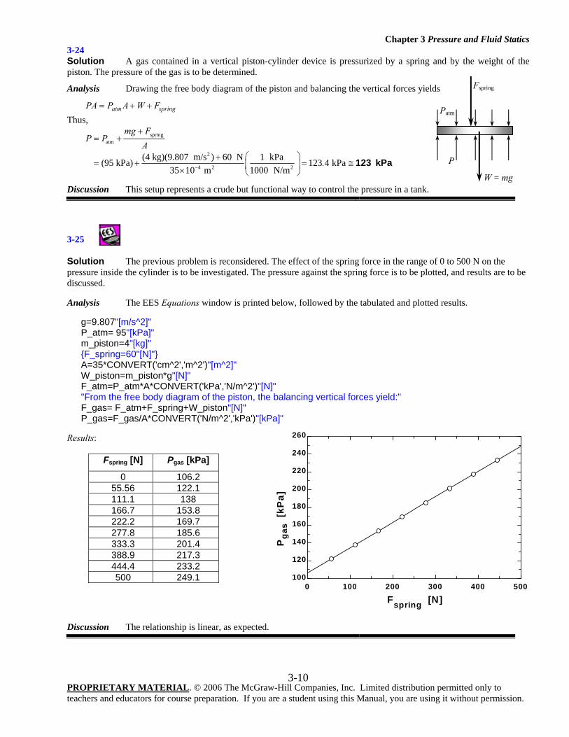
3-25
Solution The previous problem is reconsidered. The effect of the spring force in the range of 0 to 500 N on the pressure inside the cylinder is to be investigated. The pressure against the spring force is to be plotted, and results are to be discussed. Analysis The EES Equations window is printed below, followed by the tabulated and plotted results.
g=9.807"[m/s^2]" P_atm= 95"[kPa]" m_piston=4"[kg]" {F_spring=60"[N]"} A=35*CONVERT('cm^2','m^2')"[m^2]" W_piston=m_piston*g"[N]" F_atm=P_atm*A*CONVERT('kPa','N/m^2')"[N]" "From the free body diagram of the piston, the balancing vertical forces yield:" F_gas= F_atm+F_spring+W_piston"[N]" P_gas=F_gas/A*CONVERT('N/m^2','kPa')"[kPa]"
Results:
Fspring [N] Pgas [kPa]
0 106.2 55.56 122.1 111.1 138 166.7 153.8 222.2 169.7 277.8 185.6 333.3 201.4 388.9 217.3 444.4 233.2 500 249.1
Discussion The relationship is linear, as expected.
Fspring
Patm
P
W = mg
0 100 200 300 400 500100
120
140
160
180
200
220
240
260
Fspring [N]
Pga
s [k
Pa]
Chapter 3 Pressure and Fluid Statics
PROPRIETARY MATERIAL. © 2006 The McGraw-Hill Companies, Inc. Limited distribution permitted only to teachers and educators for course preparation. If you are a student using this Manual, you are using it without permission.
3-11
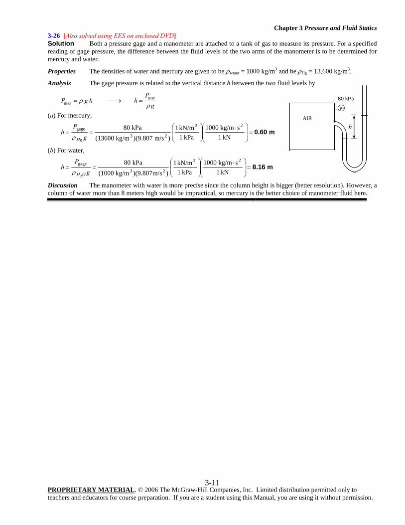
3-26 [Also solved using EES on enclosed DVD] Solution Both a pressure gage and a manometer are attached to a tank of gas to measure its pressure. For a specified reading of gage pressure, the difference between the fluid levels of the two arms of the manometer is to be determined for mercury and water.
Properties The densities of water and mercury are given to be ρwater = 1000 kg/m3 and be ρHg = 13,600 kg/m3.
Analysis The gage pressure is related to the vertical distance h between the two fluid levels by
gagegage
PP g h h
gρ
ρ= ⎯⎯→ =
(a) For mercury,
m 0.60=⎟⎟⎠
⎞⎜⎜⎝
⎛ ⋅⎟⎟⎠
⎞⎜⎜⎝
⎛==
kN 1skg/m 1000
kPa 1kN/m 1
)m/s )(9.807kg/m (13600kPa 80 22
23gage
gP
hHgρ
(b) For water,
m 8.16=⎟⎟⎠
⎞⎜⎜⎝
⎛ ⋅⎟⎟⎠
⎞⎜⎜⎝
⎛==
kN 1skg/m 1000
kPa 1kN/m 1
)m/s)(9.807kg/m (1000kPa 80 22
23gage
2g
Ph
OHρ
Discussion The manometer with water is more precise since the column height is bigger (better resolution). However, a column of water more than 8 meters high would be impractical, so mercury is the better choice of manometer fluid here.
AIR h
80 kPa
Chapter 3 Pressure and Fluid Statics
PROPRIETARY MATERIAL. © 2006 The McGraw-Hill Companies, Inc. Limited distribution permitted only to teachers and educators for course preparation. If you are a student using this Manual, you are using it without permission.
3-12
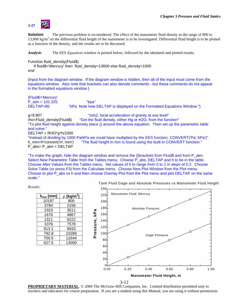
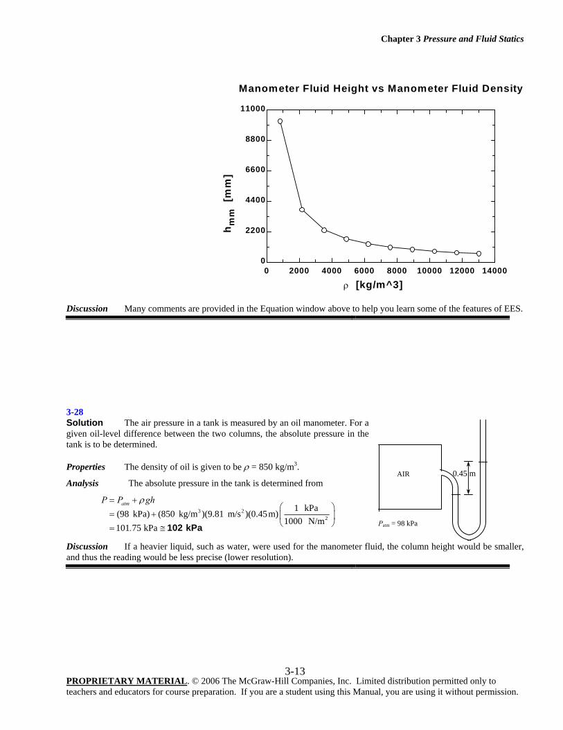
3-27
Solution The previous problem is reconsidered. The effect of the manometer fluid density in the range of 800 to 13,000 kg/m3 on the differential fluid height of the manometer is to be investigated. Differential fluid height is to be plotted as a function of the density, and the results are to be discussed. Analysis The EES Equations window is printed below, followed by the tabulated and plotted results. Function fluid_density(Fluid$) If fluid$='Mercury' then fluid_density=13600 else fluid_density=1000 end {Input from the diagram window. If the diagram window is hidden, then all of the input must come from the equations window. Also note that brackets can also denote comments - but these comments do not appear in the formatted equations window.} {Fluid$='Mercury' P_atm = 101.325 "kpa" DELTAP=80 "kPa Note how DELTAP is displayed on the Formatted Equations Window."} g=9.807 "m/s2, local acceleration of gravity at sea level" rho=Fluid_density(Fluid$) "Get the fluid density, either Hg or H2O, from the function" "To plot fluid height against density place {} around the above equation. Then set up the parametric table and solve." DELTAP = RHO*g*h/1000 "Instead of dividing by 1000 Pa/kPa we could have multiplied by the EES function, CONVERT('Pa','kPa')" h_mm=h*convert('m','mm') "The fluid height in mm is found using the built-in CONVERT function." P_abs= P_atm + DELTAP "To make the graph, hide the diagram window and remove the {}brackets from Fluid$ and from P_atm. Select New Parametric Table from the Tables menu. Choose P_abs, DELTAP and h to be in the table. Choose Alter Values from the Tables menu. Set values of h to range from 0 to 1 in steps of 0.2. Choose Solve Table (or press F3) from the Calculate menu. Choose New Plot Window from the Plot menu. Choose to plot P_abs vs h and then choose Overlay Plot from the Plot menu and plot DELTAP on the same scale." Results:
hmm [mm] ρ [kg/m3] 10197 800 3784 2156 2323 3511 1676 4867 1311 6222 1076 7578 913.1 8933 792.8 10289 700.5 11644 627.5 13000
0.00 0.20 0.40 0.60 0.80 1.000
20
40
60
80
100
120
140
160
180
200
220
240
Manometer Fluid Height, m
Pre
ssur
e, k
Pa
Tank Fluid Gage and Absolute Pressures vs Manometer Fluid Height
Absolute Pressure
Gage Pressure
Manometer Fluid: Mercury
Chapter 3 Pressure and Fluid Statics
PROPRIETARY MATERIAL. © 2006 The McGraw-Hill Companies, Inc. Limited distribution permitted only to teachers and educators for course preparation. If you are a student using this Manual, you are using it without permission.
3-13
Discussion Many comments are provided in the Equation window above to help you learn some of the features of EES.
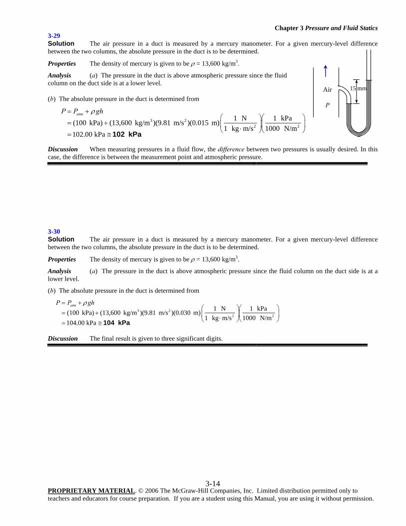
3-28 Solution The air pressure in a tank is measured by an oil manometer. For a given oil-level difference between the two columns, the absolute pressure in the tank is to be determined.
Properties The density of oil is given to be ρ = 850 kg/m3.
Analysis The absolute pressure in the tank is determined from
3 22
1 kPa(98 kPa) (850 kg/m )(9.81 m/s )(0.45m)1000 N/m
101 75 kPa
atmP P gh
.
ρ= +⎛ ⎞
= + ⎜ ⎟⎝ ⎠= ≅ 102 kPa
Discussion If a heavier liquid, such as water, were used for the manometer fluid, the column height would be smaller, and thus the reading would be less precise (lower resolution).
AIR
Patm = 98 kPa
0.45 m
0 2000 4000 6000 8000 10000 12000 140000
2200
4400
6600
8800
11000
ρ [kg/m^3]
h mm
[m
m]
Manometer Fluid Height vs Manometer Fluid Density
Chapter 3 Pressure and Fluid Statics
PROPRIETARY MATERIAL. © 2006 The McGraw-Hill Companies, Inc. Limited distribution permitted only to teachers and educators for course preparation. If you are a student using this Manual, you are using it without permission.
3-14
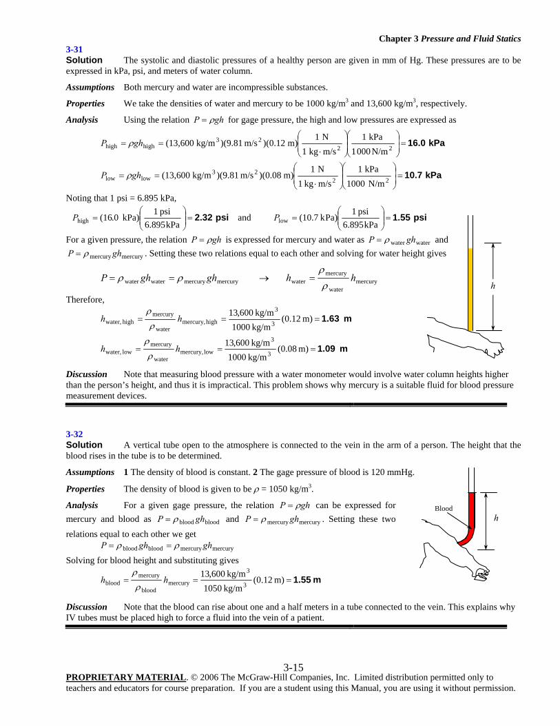
3-29 Solution The air pressure in a duct is measured by a mercury manometer. For a given mercury-level difference between the two columns, the absolute pressure in the duct is to be determined.
Properties The density of mercury is given to be ρ = 13,600 kg/m3.
Analysis (a) The pressure in the duct is above atmospheric pressure since the fluid column on the duct side is at a lower level.
(b) The absolute pressure in the duct is determined from
3 22 2
1 N 1 kPa(100 kPa) (13,600 kg/m )(9.81 m/s )(0.015 m)1 kg m/s 1000 N/m
102.00 kPa
atmP P ghρ= +⎛ ⎞⎛ ⎞
= + ⎜ ⎟⎜ ⎟⋅⎝ ⎠⎝ ⎠= ≅ 102 kPa
Discussion When measuring pressures in a fluid flow, the difference between two pressures is usually desired. In this case, the difference is between the measurement point and atmospheric pressure.
3-30 Solution The air pressure in a duct is measured by a mercury manometer. For a given mercury-level difference between the two columns, the absolute pressure in the duct is to be determined.
Properties The density of mercury is given to be ρ = 13,600 kg/m3.
Analysis (a) The pressure in the duct is above atmospheric pressure since the fluid column on the duct side is at a lower level.
(b) The absolute pressure in the duct is determined from
3 22 2
1 N 1 kPa(100 kPa) (13,600 kg/m )(9.81 m/s )(0.030 m)1 kg m/s 1000 N/m
104.00 kPa
atmP P ghρ= +⎛ ⎞⎛ ⎞
= + ⎜ ⎟⎜ ⎟⋅⎝ ⎠⎝ ⎠= ≅ 104 kPa
Discussion The final result is given to three significant digits.
Air
P
15 mm
Chapter 3 Pressure and Fluid Statics
PROPRIETARY MATERIAL. © 2006 The McGraw-Hill Companies, Inc. Limited distribution permitted only to teachers and educators for course preparation. If you are a student using this Manual, you are using it without permission.
3-15
3-31 Solution The systolic and diastolic pressures of a healthy person are given in mm of Hg. These pressures are to be expressed in kPa, psi, and meters of water column.
Assumptions Both mercury and water are incompressible substances.
Properties We take the densities of water and mercury to be 1000 kg/m3 and 13,600 kg/m3, respectively.
Analysis Using the relation ghP ρ= for gage pressure, the high and low pressures are expressed as
kPa 10.7
kPa 16.0
=⎟⎟⎠
⎞⎜⎜⎝
⎛⎟⎟⎠
⎞⎜⎜⎝
⎛
⋅==
=⎟⎟⎠
⎞⎜⎜⎝
⎛⎟⎟⎠
⎞⎜⎜⎝
⎛
⋅==
2223
lowlow
2223
highhigh
N/m 1000kPa 1
m/skg 1N 1
m) )(0.08m/s )(9.81kg/m (13,600
N/m000 1kPa 1
m/skg 1N 1
m) )(0.12m/s )(9.81kg/m (13,600
ghP
ghP
ρ
ρ
Noting that 1 psi = 6.895 kPa,
psi 2.32=⎟⎟⎠
⎞⎜⎜⎝
⎛=
kPa6.895psi 1
kPa) 0.(16highP and psi 1.55=⎟⎟⎠
⎞⎜⎜⎝
⎛=
kPa6.895psi 1
Pa)k (10.7lowP
For a given pressure, the relation ghP ρ= is expressed for mercury and water as waterwater ghP ρ= and
mercurymercury ghP ρ= . Setting these two relations equal to each other and solving for water height gives
mercurywater
mercurywatermercurymercurywaterwater hhghghP
ρρ
ρρ =→==
Therefore,
m 1.09
m 1.63
===
===
m) 08.0(kg/m 1000kg/m 600,13
m) 12.0(kg/m 1000kg/m 600,13
3
3
low mercury,water
mercurylow water,
3
3
high mercury,water
mercuryhigh water,
hh
hh
ρ
ρ
ρ
ρ
Discussion Note that measuring blood pressure with a water monometer would involve water column heights higher than the person’s height, and thus it is impractical. This problem shows why mercury is a suitable fluid for blood pressure measurement devices.
3-32 Solution A vertical tube open to the atmosphere is connected to the vein in the arm of a person. The height that the blood rises in the tube is to be determined.
Assumptions 1 The density of blood is constant. 2 The gage pressure of blood is 120 mmHg.
Properties The density of blood is given to be ρ = 1050 kg/m3.
Analysis For a given gage pressure, the relation ghP ρ= can be expressed for mercury and blood as bloodblood ghP ρ= and mercurymercury ghP ρ= . Setting these two
relations equal to each other we get mercurymercurybloodblood ghghP ρρ ==
Solving for blood height and substituting gives
m 1.55=== m) 12.0(kg/m 1050kg/m 600,13
3
3
mercuryblood
mercuryblood hh
ρ
ρ
Discussion Note that the blood can rise about one and a half meters in a tube connected to the vein. This explains why IV tubes must be placed high to force a fluid into the vein of a patient.
hBlood
h
Chapter 3 Pressure and Fluid Statics
PROPRIETARY MATERIAL. © 2006 The McGraw-Hill Companies, Inc. Limited distribution permitted only to teachers and educators for course preparation. If you are a student using this Manual, you are using it without permission.
3-16
3-33 Solution A man is standing in water vertically while being completely submerged. The difference between the pressure acting on his head and the pressure acting on his toes is to be determined.
Assumptions Water is an incompressible substance, and thus the density does not change with depth.
Properties We take the density of water to be ρ =1000 kg/m3.
Analysis The pressures at the head and toes of the person can be expressed as
headatmhead ghPP ρ+= and toeatmtoe ghPP ρ+=
where h is the vertical distance of the location in water from the free surface. The pressure difference between the toes and the head is determined by subtracting the first relation above from the second,
)( headtoeheadtoeheadtoe hhgghghPP −=−=− ρρρ
Substituting,
kPa 17.7=⎟⎟⎠
⎞⎜⎜⎝
⎛⎟⎟⎠
⎞⎜⎜⎝
⎛
⋅=−
2223
headtoeN/m1000
kPa1m/skg1N1
0) - m )(1.80m/s )(9.81kg/m (1000PP
Discussion This problem can also be solved by noting that the atmospheric pressure (1 atm = 101.325 kPa) is equivalent to 10.3-m of water height, and finding the pressure that corresponds to a water height of 1.8 m.
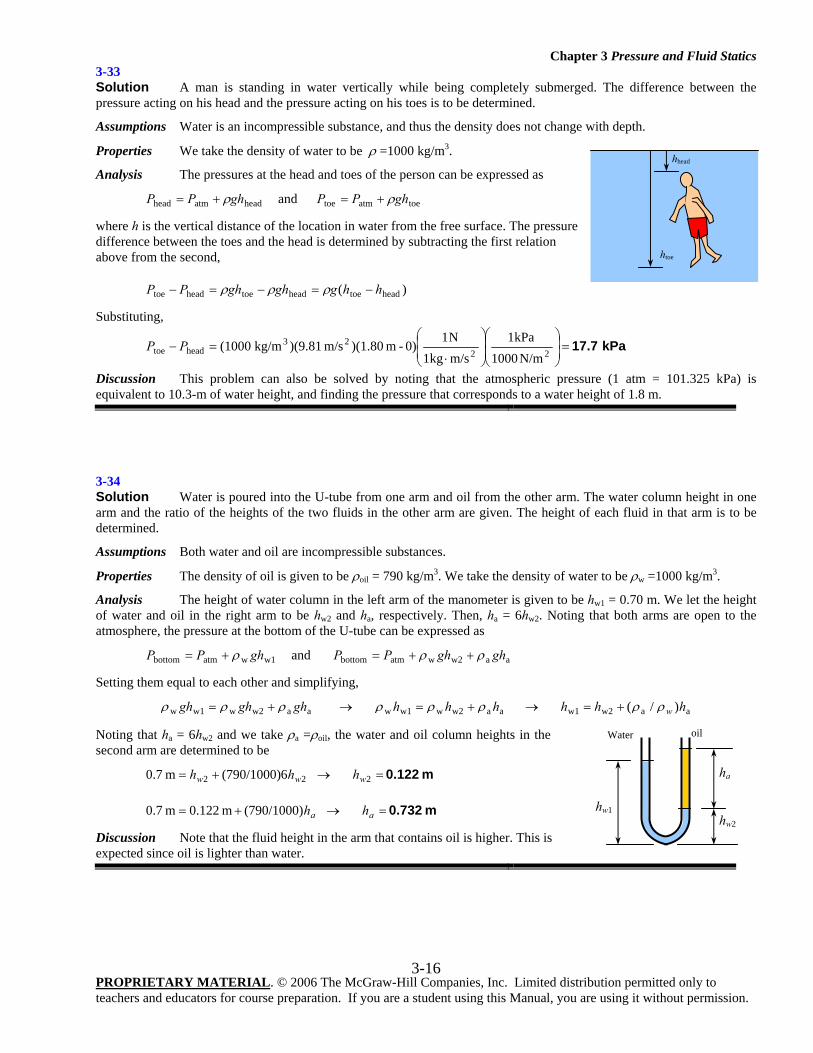
3-34 Solution Water is poured into the U-tube from one arm and oil from the other arm. The water column height in one arm and the ratio of the heights of the two fluids in the other arm are given. The height of each fluid in that arm is to be determined.
Assumptions Both water and oil are incompressible substances.
Properties The density of oil is given to be ρoil = 790 kg/m3. We take the density of water to be ρw =1000 kg/m3.
Analysis The height of water column in the left arm of the manometer is given to be hw1 = 0.70 m. We let the height of water and oil in the right arm to be hw2 and ha, respectively. Then, ha = 6hw2. Noting that both arms are open to the atmosphere, the pressure at the bottom of the U-tube can be expressed as
w1watmbottom ghPP ρ+= and aaw2watmbottom ghghPP ρρ ++=
Setting them equal to each other and simplifying,
aaw2w1aaw2ww1waaw2ww1w )/( hhhhhhghghgh wρρρρρρρρ +=→+=→+=
Noting that ha = 6hw2 and we take ρa =ρoil, the water and oil column heights in the second arm are determined to be
m 0.122 =→+= 222 6(790/1000)m 0.7 www hhh
m 0.732 =→+= aa hh (790/1000)m 122.0m 0.7
Discussion Note that the fluid height in the arm that contains oil is higher. This is expected since oil is lighter than water.
ha
hw2
hw1
oil Water
hhead
htoe
Chapter 3 Pressure and Fluid Statics
PROPRIETARY MATERIAL. © 2006 The McGraw-Hill Companies, Inc. Limited distribution permitted only to teachers and educators for course preparation. If you are a student using this Manual, you are using it without permission.
3-17
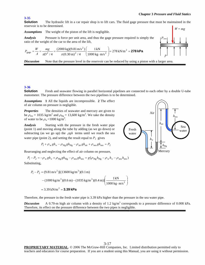
3-35 Solution The hydraulic lift in a car repair shop is to lift cars. The fluid gage pressure that must be maintained in the reservoir is to be determined.
Assumptions The weight of the piston of the lift is negligible.
Analysis Pressure is force per unit area, and thus the gage pressure required is simply the ratio of the weight of the car to the area of the lift,
kPa 278==⎟⎟⎠
⎞⎜⎜⎝
⎛
⋅=== 2
22
2
2gage kN/m 278m/skg 1000
kN 14/m) 30.0(
)m/s kg)(9.81 2000(4/ ππD
mgA
WP
Discussion Note that the pressure level in the reservoir can be reduced by using a piston with a larger area.
3-36 Solution Fresh and seawater flowing in parallel horizontal pipelines are connected to each other by a double U-tube manometer. The pressure difference between the two pipelines is to be determined.
Assumptions 1 All the liquids are incompressible. 2 The effect of air column on pressure is negligible.
Properties The densities of seawater and mercury are given to be ρsea = 1035 kg/m3 and ρHg = 13,600 kg/m3. We take the density of water to be ρw =1000 kg/m3.
Analysis Starting with the pressure in the fresh water pipe (point 1) and moving along the tube by adding (as we go down) or subtracting (as we go up) the ghρ terms until we reach the sea water pipe (point 2), and setting the result equal to P2 gives
2seaseaairairHgHgw1 PghghghghP w =+−−+ ρρρρ
Rearranging and neglecting the effect of air column on pressure,
)( seaseawHgHgseaseaHgHgw21 hhhgghghghPP ww ρρρρρρ −−=−+−=−
Substituting,
kPa 3.39==
⎟⎟⎠
⎞⎜⎜⎝
⎛
⋅−−
=−
2
233
3221
kN/m 39.3
m/skg 1000kN 1m)] 4.0)(kg/m (1035m) 6.0)(kg/m (1000
m) 1.0)(kg/m )[(13600m/s (9.81PP
Therefore, the pressure in the fresh water pipe is 3.39 kPa higher than the pressure in the sea water pipe.
Discussion A 0.70-m high air column with a density of 1.2 kg/m3 corresponds to a pressure difference of 0.008 kPa. Therefore, its effect on the pressure difference between the two pipes is negligible.
W = mg
Patm
P
Fresh water
hsea
hair Sea
water
Mercury
Air
hHg
hw
Chapter 3 Pressure and Fluid Statics
PROPRIETARY MATERIAL. © 2006 The McGraw-Hill Companies, Inc. Limited distribution permitted only to teachers and educators for course preparation. If you are a student using this Manual, you are using it without permission.
3-18
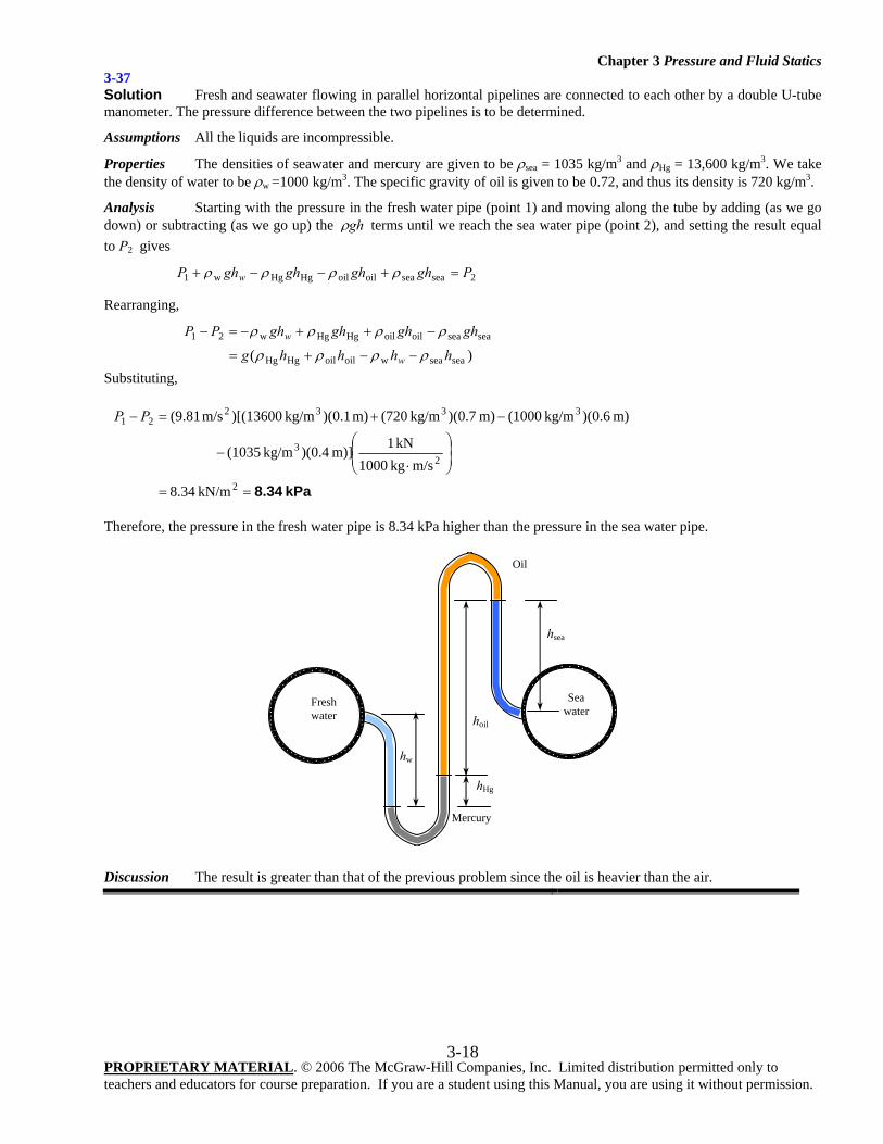
3-37 Solution Fresh and seawater flowing in parallel horizontal pipelines are connected to each other by a double U-tube manometer. The pressure difference between the two pipelines is to be determined.
Assumptions All the liquids are incompressible.
Properties The densities of seawater and mercury are given to be ρsea = 1035 kg/m3 and ρHg = 13,600 kg/m3. We take the density of water to be ρw =1000 kg/m3. The specific gravity of oil is given to be 0.72, and thus its density is 720 kg/m3.
Analysis Starting with the pressure in the fresh water pipe (point 1) and moving along the tube by adding (as we go down) or subtracting (as we go up) the ghρ terms until we reach the sea water pipe (point 2), and setting the result equal to P2 gives
2seaseaoiloilHgHgw1 PghghghghP w =+−−+ ρρρρ
Rearranging,
)( seaseawoiloilHgHg
seaseaoiloilHgHgw21
hhhhg
ghghghghPP
w
w
ρρρρ
ρρρρ
−−+=
−++−=−
Substituting,
kPa 8.34==
⎟⎟⎠
⎞⎜⎜⎝
⎛
⋅−
−+=−
2
23
333221
kN/m 34.8
m/skg 1000kN 1m)] 4.0)(kg/m (1035
m) 6.0)(kg/m (1000 m) 7.0)(kg/m (720m) 1.0)(kg/m )[(13600m/s (9.81PP
Therefore, the pressure in the fresh water pipe is 8.34 kPa higher than the pressure in the sea water pipe.
Discussion The result is greater than that of the previous problem since the oil is heavier than the air.
Fresh water
hw
hsea
hoil
Sea
water
Mercury
Oil
hHg
Chapter 3 Pressure and Fluid Statics
PROPRIETARY MATERIAL. © 2006 The McGraw-Hill Companies, Inc. Limited distribution permitted only to teachers and educators for course preparation. If you are a student using this Manual, you are using it without permission.
3-19
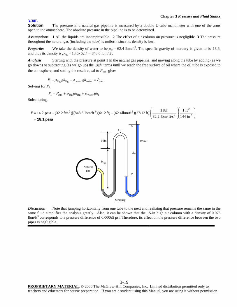
3-38E Solution The pressure in a natural gas pipeline is measured by a double U-tube manometer with one of the arms open to the atmosphere. The absolute pressure in the pipeline is to be determined.
Assumptions 1 All the liquids are incompressible. 2 The effect of air column on pressure is negligible. 3 The pressure throughout the natural gas (including the tube) is uniform since its density is low.
Properties We take the density of water to be ρw = 62.4 lbm/ft3. The specific gravity of mercury is given to be 13.6, and thus its density is ρHg = 13.6×62.4 = 848.6 lbm/ft3.
Analysis Starting with the pressure at point 1 in the natural gas pipeline, and moving along the tube by adding (as we go down) or subtracting (as we go up) the ghρ terms until we reach the free surface of oil where the oil tube is exposed to the atmosphere, and setting the result equal to Patm gives
atmPghghP =−− waterwaterHgHg1 ρρ
Solving for P1,
1waterHgHgatm1 ghghPP ρρ ++=
Substituting,
psia 18.1=
⎟⎟⎠
⎞⎜⎜⎝
⎛⎟⎟⎠
⎞⎜⎜⎝
⎛
⋅++=
2
2
2332
in 144ft 1
ft/slbm 32.2lbf 1
ft)] )(27/12lbm/ft(62.4ft) )(6/12lbm/ft )[(848.6ft/s 2.32(psia 14.2P
Discussion Note that jumping horizontally from one tube to the next and realizing that pressure remains the same in the same fluid simplifies the analysis greatly. Also, it can be shown that the 15-in high air column with a density of 0.075 lbm/ft3 corresponds to a pressure difference of 0.00065 psi. Therefore, its effect on the pressure difference between the two pipes is negligible.
hw
Natural
gas
hHg
10in
Mercury
Water
Air
Chapter 3 Pressure and Fluid Statics
PROPRIETARY MATERIAL. © 2006 The McGraw-Hill Companies, Inc. Limited distribution permitted only to teachers and educators for course preparation. If you are a student using this Manual, you are using it without permission.
3-20
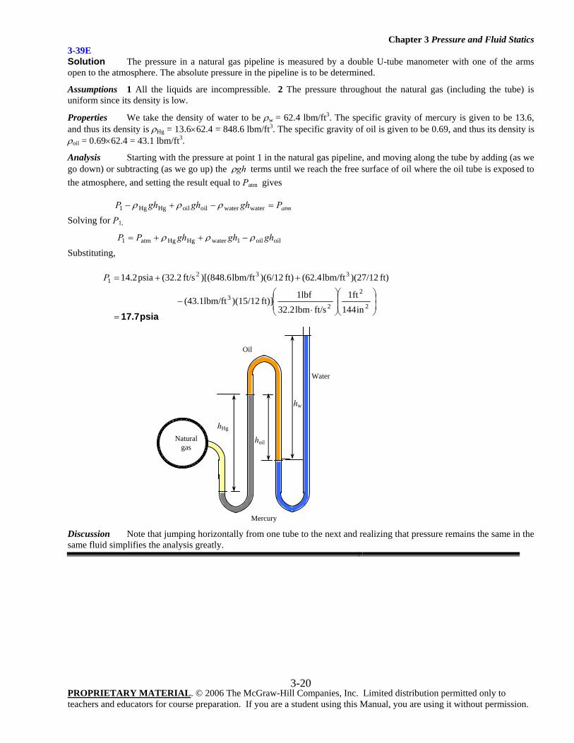
3-39E Solution The pressure in a natural gas pipeline is measured by a double U-tube manometer with one of the arms open to the atmosphere. The absolute pressure in the pipeline is to be determined.
Assumptions 1 All the liquids are incompressible. 2 The pressure throughout the natural gas (including the tube) is uniform since its density is low.
Properties We take the density of water to be ρw = 62.4 lbm/ft3. The specific gravity of mercury is given to be 13.6, and thus its density is ρHg = 13.6×62.4 = 848.6 lbm/ft3. The specific gravity of oil is given to be 0.69, and thus its density is ρoil = 0.69×62.4 = 43.1 lbm/ft3.
Analysis Starting with the pressure at point 1 in the natural gas pipeline, and moving along the tube by adding (as we go down) or subtracting (as we go up) the ghρ terms until we reach the free surface of oil where the oil tube is exposed to the atmosphere, and setting the result equal to Patm gives
atmPghghghP =−+− waterwateroiloilHgHg1 ρρρ
Solving for P1,
oiloil1waterHgHgatm1 ghghghPP ρρρ −++=
Substituting,
psia17.7=⎟⎟⎠
⎞⎜⎜⎝
⎛⎟⎟⎠
⎞⎜⎜⎝
⎛
⋅−
++=
2
2
23
3321
in144ft1
ft/slbm32.2lbf1
ft)] )(15/12lbm/ft(43.1
ft) )(27/12lbm/ft(62.4ft) )(6/12lbm/ft)[(848.6ft/s 2.32(psia4.21P
Discussion Note that jumping horizontally from one tube to the next and realizing that pressure remains the same in the same fluid simplifies the analysis greatly.
hw
Natural
gas
hHg
Mercury
Water
Oil
hoil
Chapter 3 Pressure and Fluid Statics
PROPRIETARY MATERIAL. © 2006 The McGraw-Hill Companies, Inc. Limited distribution permitted only to teachers and educators for course preparation. If you are a student using this Manual, you are using it without permission.
3-21
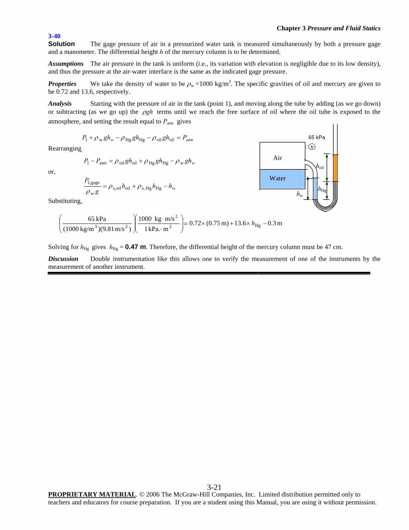
3-40 Solution The gage pressure of air in a pressurized water tank is measured simultaneously by both a pressure gage and a manometer. The differential height h of the mercury column is to be determined.
Assumptions The air pressure in the tank is uniform (i.e., its variation with elevation is negligible due to its low density), and thus the pressure at the air-water interface is the same as the indicated gage pressure.
Properties We take the density of water to be ρw =1000 kg/m3. The specific gravities of oil and mercury are given to be 0.72 and 13.6, respectively.
Analysis Starting with the pressure of air in the tank (point 1), and moving along the tube by adding (as we go down) or subtracting (as we go up) the ghρ terms until we reach the free surface of oil where the oil tube is exposed to the atmosphere, and setting the result equal to Patm gives
atmw PghghghP =−−+ oiloilHgHgw1 ρρρ
Rearranging,
wghghghPP wHgHgoiloilatm1 ρρρ −+=−
or,
whhhg
P−+= HgHg s,oiloils,
w
gage,1 ρρρ
Substituting,
m 3.013.6m) (0.7572.0m kPa.1m/s kg1000
)m/s (9.81) kg/m(1000 kPa65
Hg2
2
23 −×+×=⎟⎟⎠
⎞⎜⎜⎝
⎛
⋅⋅
⎟⎟⎠
⎞⎜⎜⎝
⎛h
Solving for hHg gives hHg = 0.47 m. Therefore, the differential height of the mercury column must be 47 cm.
Discussion Double instrumentation like this allows one to verify the measurement of one of the instruments by the measurement of another instrument.
Air
Water
hoil
65 kPa
hHg hw
Chapter 3 Pressure and Fluid Statics
PROPRIETARY MATERIAL. © 2006 The McGraw-Hill Companies, Inc. Limited distribution permitted only to teachers and educators for course preparation. If you are a student using this Manual, you are using it without permission.
3-22
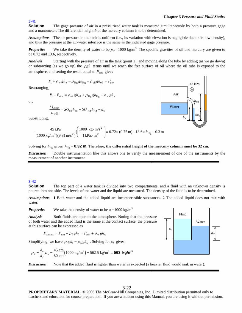
3-41 Solution The gage pressure of air in a pressurized water tank is measured simultaneously by both a pressure gage and a manometer. The differential height h of the mercury column is to be determined.
Assumptions The air pressure in the tank is uniform (i.e., its variation with elevation is negligible due to its low density), and thus the pressure at the air-water interface is the same as the indicated gage pressure.
Properties We take the density of water to be ρw =1000 kg/m3. The specific gravities of oil and mercury are given to be 0.72 and 13.6, respectively.
Analysis Starting with the pressure of air in the tank (point 1), and moving along the tube by adding (as we go down) or subtracting (as we go up) the ghρ terms until we reach the free surface of oil where the oil tube is exposed to the atmosphere, and setting the result equal to Patm gives
atmw PghghghP =−−+ oiloilHgHgw1 ρρρ
Rearranging,
wghghghPP wHgHgoiloilatm1 ρρρ −+=−
or,
whhSGhSGg
P−+= HgHg oiloil
w
gage,1
ρ
Substituting,
m 3.013.6m) (0.7572.0mkPa. 1m/skg 1000]
)m/s (9.81)kg/m (1000kPa 45
Hg2
2
23−×+×=⎟
⎟⎠
⎞⎜⎜⎝
⎛
⋅
⋅ h
Solving for hHg gives hHg = 0.32 m. Therefore, the differential height of the mercury column must be 32 cm.
Discussion Double instrumentation like this allows one to verify the measurement of one of the instruments by the measurement of another instrument.
3-42 Solution The top part of a water tank is divided into two compartments, and a fluid with an unknown density is poured into one side. The levels of the water and the liquid are measured. The density of the fluid is to be determined.
Assumptions 1 Both water and the added liquid are incompressible substances. 2 The added liquid does not mix with water.
Properties We take the density of water to be ρ =1000 kg/m3.
Analysis Both fluids are open to the atmosphere. Noting that the pressure of both water and the added fluid is the same at the contact surface, the pressure at this surface can be expressed as
wwatmffatmcontact ghPghPP ρρ +=+=
Simplifying, we have f f w wgh ghρ ρ= . Solving for ρf gives
( )3 345 cm 1000 kg/m 562 5 kg/m80 cm
wf w
f
h.
hρ ρ= = = ≅ 3563 kg/m
Discussion Note that the added fluid is lighter than water as expected (a heavier fluid would sink in water).
hf hw
Fluid
Water
Air
hoil
45 kPa
hHg hw
Water
Chapter 3 Pressure and Fluid Statics
PROPRIETARY MATERIAL. © 2006 The McGraw-Hill Companies, Inc. Limited distribution permitted only to teachers and educators for course preparation. If you are a student using this Manual, you are using it without permission.
3-23
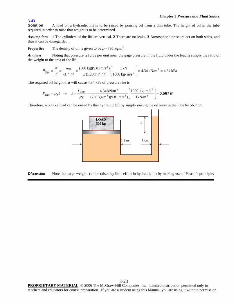
3-43 Solution A load on a hydraulic lift is to be raised by pouring oil from a thin tube. The height of oil in the tube required in order to raise that weight is to be determined.
Assumptions 1 The cylinders of the lift are vertical. 2 There are no leaks. 3 Atmospheric pressure act on both sides, and thus it can be disregarded.
Properties The density of oil is given to be ρ =780 kg/m3.
Analysis Noting that pressure is force per unit area, the gage pressure in the fluid under the load is simply the ratio of the weight to the area of the lift,
kPa 4.34kN/m 34.4m/skg 1000
kN 14/m) 20.1(
)m/s kg)(9.81 500(4/
222
2
2gage ==⎟⎟⎠
⎞⎜⎜⎝
⎛
⋅===
ππDmg
AWP
The required oil height that will cause 4.34 kPa of pressure rise is
m 0.567=⎟⎟⎠
⎞⎜⎜⎝
⎛ ⋅==→=
2
2
23
2gage
gagekN/m1
m/skg 0001)m/s )(9.81kg/m (780
kN/m 34.4 g
PhghP
ρρ
Therefore, a 500 kg load can be raised by this hydraulic lift by simply raising the oil level in the tube by 56.7 cm.
Discussion Note that large weights can be raised by little effort in hydraulic lift by making use of Pascal’s principle.
LOAD 500 kg h
1.2 m 1 cm
Chapter 3 Pressure and Fluid Statics
PROPRIETARY MATERIAL. © 2006 The McGraw-Hill Companies, Inc. Limited distribution permitted only to teachers and educators for course preparation. If you are a student using this Manual, you are using it without permission.
3-24
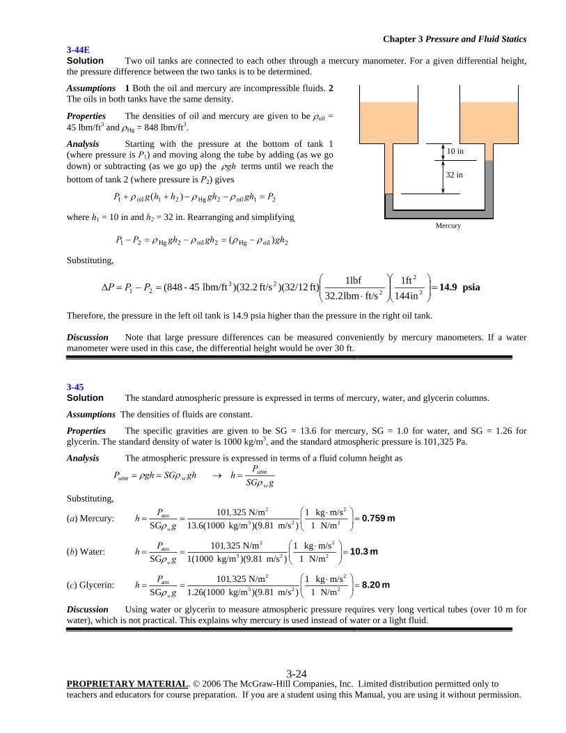
3-44E Solution Two oil tanks are connected to each other through a mercury manometer. For a given differential height, the pressure difference between the two tanks is to be determined.
Assumptions 1 Both the oil and mercury are incompressible fluids. 2 The oils in both tanks have the same density.
Properties The densities of oil and mercury are given to be ρoil = 45 lbm/ft3 and ρHg = 848 lbm/ft3.
Analysis Starting with the pressure at the bottom of tank 1 (where pressure is P1) and moving along the tube by adding (as we go down) or subtracting (as we go up) the ghρ terms until we reach the bottom of tank 2 (where pressure is P2) gives
21oil2Hg21oil1 )( PghghhhgP =−−++ ρρρ
where h1 = 10 in and h2 = 32 in. Rearranging and simplifying,
2oilHg2oil2Hg21 )( ghghghPP ρρρρ −=−=−
Substituting,
psia 14.9=⎟⎟⎠
⎞⎜⎜⎝
⎛⎟⎟⎠
⎞⎜⎜⎝
⎛
⋅=−=Δ 2
2
223
21 in144ft1
ft/slbm32.2lbf1ft) )(32/12ft/s 2.32()lbm/ft 45- (848PPP
Therefore, the pressure in the left oil tank is 14.9 psia higher than the pressure in the right oil tank. Discussion Note that large pressure differences can be measured conveniently by mercury manometers. If a water manometer were used in this case, the differential height would be over 30 ft.
3-45 Solution The standard atmospheric pressure is expressed in terms of mercury, water, and glycerin columns.
Assumptions The densities of fluids are constant.
Properties The specific gravities are given to be SG = 13.6 for mercury, SG = 1.0 for water, and SG = 1.26 for glycerin. The standard density of water is 1000 kg/m3, and the standard atmospheric pressure is 101,325 Pa.
Analysis The atmospheric pressure is expressed in terms of a fluid column height as
ghSGghP watm ρρ == → gSG
Ph
w
atm
ρ=
Substituting,
(a) Mercury: 2 2
atm3 2 2
101 325 N/m 1 kg m/sSG 13.6(1000 kg/m )(9.81 m/s ) 1 N/mw
P ,hgρ
⎛ ⎞⋅= = =⎜ ⎟
⎝ ⎠0.759 m
(b) Water: 2 2
atm3 2 2
101 325 N/m 1 kg m/sSG 1(1000 kg/m )(9.81 m/s ) 1 N/mw
P ,hgρ
⎛ ⎞⋅= = =⎜ ⎟
⎝ ⎠10.3 m
(c) Glycerin: 2 2
atm3 2 2
101 325 N/m 1 kg m/sSG 1.26(1000 kg/m )(9.81 m/s ) 1 N/mw
P ,hgρ
⎛ ⎞⋅= = =⎜ ⎟
⎝ ⎠8.20 m
Discussion Using water or glycerin to measure atmospheric pressure requires very long vertical tubes (over 10 m for water), which is not practical. This explains why mercury is used instead of water or a light fluid.
32 in
10 in
Mercury
Chapter 3 Pressure and Fluid Statics
PROPRIETARY MATERIAL. © 2006 The McGraw-Hill Companies, Inc. Limited distribution permitted only to teachers and educators for course preparation. If you are a student using this Manual, you are using it without permission.
3-25
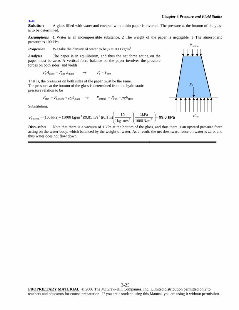
3-46 Solution A glass filled with water and covered with a thin paper is inverted. The pressure at the bottom of the glass is to be determined.
Assumptions 1 Water is an incompressible substance. 2 The weight of the paper is negligible. 3 The atmospheric pressure is 100 kPa.
Properties We take the density of water to be ρ =1000 kg/m3.
Analysis The paper is in equilibrium, and thus the net force acting on the paper must be zero. A vertical force balance on the paper involves the pressure forces on both sides, and yields
glassatmglass1 APAP = → atm1 PP =
That is, the pressures on both sides of the paper must be the same. The pressure at the bottom of the glass is determined from the hydrostatic pressure relation to be
glassbottomatm ghPP ρ+= → glassatmbottom ghPP ρ−=
Substituting,
kPa 99.0=⎟⎟⎠
⎞⎜⎜⎝
⎛⎟⎟⎠
⎞⎜⎜⎝
⎛
⋅−= 22
23bottom N/m1000
kPa1m/skg1N1
m) )(0.1m/s )(9.81kg/m (1000 kPa)100(P
Discussion Note that there is a vacuum of 1 kPa at the bottom of the glass, and thus there is an upward pressure force acting on the water body, which balanced by the weight of water. As a result, the net downward force on water is zero, and thus water does not flow down.
Patm
P1
Pbottom
Chapter 3 Pressure and Fluid Statics
PROPRIETARY MATERIAL. © 2006 The McGraw-Hill Companies, Inc. Limited distribution permitted only to teachers and educators for course preparation. If you are a student using this Manual, you are using it without permission.
3-26
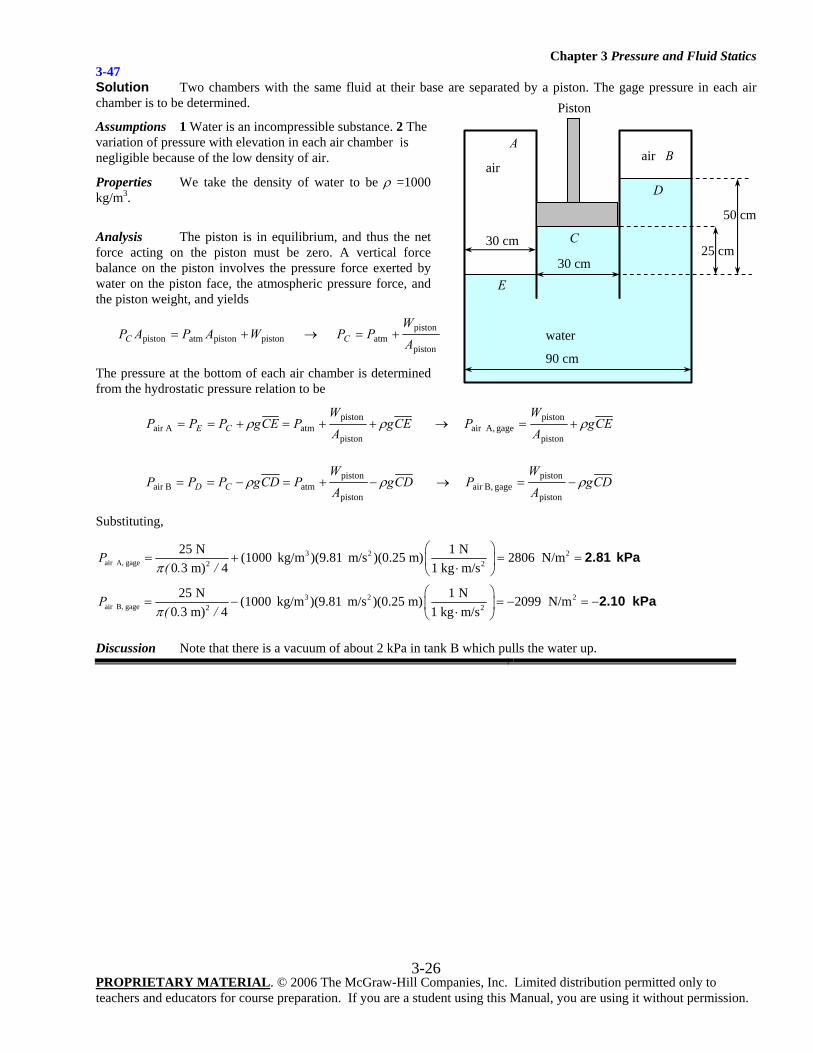
3-47 Solution Two chambers with the same fluid at their base are separated by a piston. The gage pressure in each air chamber is to be determined.
Assumptions 1 Water is an incompressible substance. 2 The variation of pressure with elevation in each air chamber is negligible because of the low density of air.
Properties We take the density of water to be ρ =1000 kg/m3.
Analysis The piston is in equilibrium, and thus the net force acting on the piston must be zero. A vertical force balance on the piston involves the pressure force exerted by water on the piston face, the atmospheric pressure force, and the piston weight, and yields
pistonpistonatmpiston WAPAPC += → piston
pistonatm A
WPPC +=
The pressure at the bottom of each air chamber is determined from the hydrostatic pressure relation to be
CEgAW
PCEgPPP CE ρρ ++=+==piston
pistonatmAair → CEg
AW
P ρ+=piston
pistongage A,air
CDgAW
PCDgPPP CD ρρ −+=−==piston
pistonatmBair → CDg
AW
P ρ−=piston
pistongage B,air
Substituting,
3 2 2air A, gage 2 2
25 N 1 N(1000 kg/m )(9.81 m/s )(0.25 m) 2806 N/m0 3 m) 4 1 kg m/s
P( . /π
⎛ ⎞= + = =⎜ ⎟⋅⎝ ⎠
2.81 kPa
3 2 2air B, gage 2 2
25 N 1 N(1000 kg/m )(9.81 m/s )(0.25 m) 2099 N/m0 3 m) 4 1 kg m/s
P( . /π
⎛ ⎞= − = − = −⎜ ⎟⋅⎝ ⎠
2.10 kPa
Discussion Note that there is a vacuum of about 2 kPa in tank B which pulls the water up.
airair
water
Piston
50 cm
25 cm 30 cm
AB
E
D
30 cm
90 cm
C
Chapter 3 Pressure and Fluid Statics
PROPRIETARY MATERIAL. © 2006 The McGraw-Hill Companies, Inc. Limited distribution permitted only to teachers and educators for course preparation. If you are a student using this Manual, you are using it without permission.
3-27
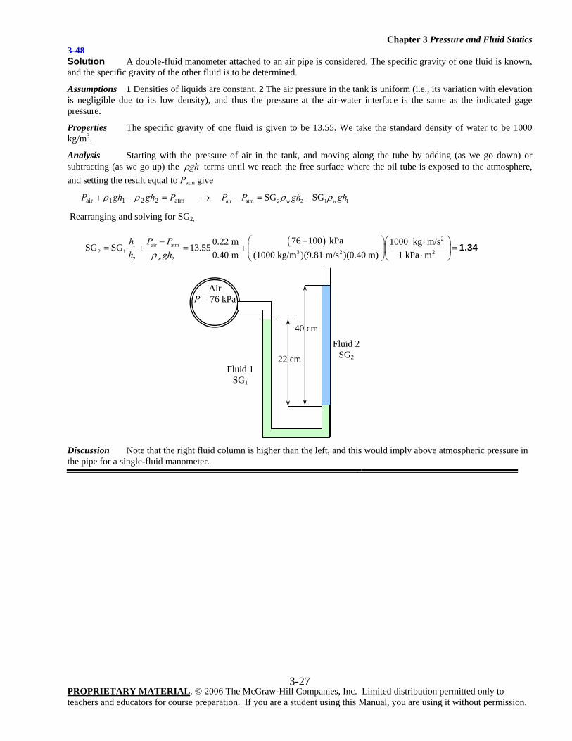
3-48 Solution A double-fluid manometer attached to an air pipe is considered. The specific gravity of one fluid is known, and the specific gravity of the other fluid is to be determined.
Assumptions 1 Densities of liquids are constant. 2 The air pressure in the tank is uniform (i.e., its variation with elevation is negligible due to its low density), and thus the pressure at the air-water interface is the same as the indicated gage pressure.
Properties The specific gravity of one fluid is given to be 13.55. We take the standard density of water to be 1000 kg/m3.
Analysis Starting with the pressure of air in the tank, and moving along the tube by adding (as we go down) or subtracting (as we go up) the ghρ terms until we reach the free surface where the oil tube is exposed to the atmosphere, and setting the result equal to Patm give
atm2211air PghghP =−+ ρρ → air atm 2 w 2 1 1SG SG wP P gh ghρ ρ− = −
Rearranging and solving for SG2,
( ) 2
air atm12 1 3 2 2
2 w 2
76 100 kPa0.22 m 1000 kg m/sSG SG 13.550.40 m (1000 kg/m )(9.81 m/s )(0.40 m) 1 kPa m
P Phh ghρ
−⎛ ⎞⎛ ⎞− ⋅= + = + =⎜ ⎟⎜ ⎟⋅⎝ ⎠⎝ ⎠
1.34
Discussion Note that the right fluid column is higher than the left, and this would imply above atmospheric pressure in the pipe for a single-fluid manometer.
Air P = 76 kPa
22 cm
40 cm
Fluid 1 SG1
Fluid 2 SG2
Chapter 3 Pressure and Fluid Statics
PROPRIETARY MATERIAL. © 2006 The McGraw-Hill Companies, Inc. Limited distribution permitted only to teachers and educators for course preparation. If you are a student using this Manual, you are using it without permission.
3-28
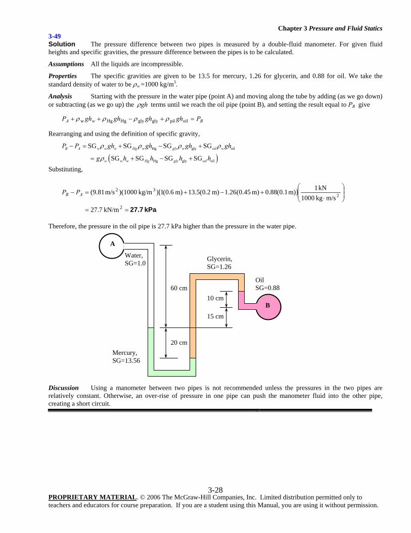
3-49 Solution The pressure difference between two pipes is measured by a double-fluid manometer. For given fluid heights and specific gravities, the pressure difference between the pipes is to be calculated.
Assumptions All the liquids are incompressible.
Properties The specific gravities are given to be 13.5 for mercury, 1.26 for glycerin, and 0.88 for oil. We take the standard density of water to be ρw =1000 kg/m3.
Analysis Starting with the pressure in the water pipe (point A) and moving along the tube by adding (as we go down) or subtracting (as we go up) the ghρ terms until we reach the oil pipe (point B), and setting the result equal to PB give
BwA PghghghghP =+−++ oilpilglyglyHgHgw ρρρρ
Rearranging and using the definition of specific gravity,
( )Hg gly oil
Hg gly oil
SG SG SG SG
SG SG SG SGB A w w w Hg w gly w oil w
w w w Hg gly oil
P P gh gh gh gh
g h h h h
ρ ρ ρ ρ
ρ
− = + − +
= + − +
Substituting,
kPa 27.7==
⎟⎟⎠
⎞⎜⎜⎝
⎛
⋅+−+=−
2
232
kN/m7.27
m/s kg1000 kN1m)] 1.0(88.0m) 45.0(26.1m) 2.0(5.13m) 6.0(1)[ kg/m)(1000m/s (9.81AB PP
Therefore, the pressure in the oil pipe is 27.7 kPa higher than the pressure in the water pipe.
Discussion Using a manometer between two pipes is not recommended unless the pressures in the two pipes are relatively constant. Otherwise, an over-rise of pressure in one pipe can push the manometer fluid into the other pipe, creating a short circuit.
Mercury, SG=13.56
Glycerin, SG=1.26
Oil SG=0.88
Water, SG=1.0
A
B
60 cm
20 cm
15 cm
10 cm
Chapter 3 Pressure and Fluid Statics
PROPRIETARY MATERIAL. © 2006 The McGraw-Hill Companies, Inc. Limited distribution permitted only to teachers and educators for course preparation. If you are a student using this Manual, you are using it without permission.
3-29
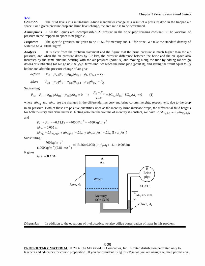
3-50 Solution The fluid levels in a multi-fluid U-tube manometer change as a result of a pressure drop in the trapped air space. For a given pressure drop and brine level change, the area ratio is to be determined.
Assumptions 1 All the liquids are incompressible. 2 Pressure in the brine pipe remains constant. 3 The variation of pressure in the trapped air space is negligible.
Properties The specific gravities are given to be 13.56 for mercury and 1.1 for brine. We take the standard density of water to be ρw =1000 kg/m3.
Analysis It is clear from the problem statement and the figure that the brine pressure is much higher than the air pressure, and when the air pressure drops by 0.7 kPa, the pressure difference between the brine and the air space also increases by the same amount. Starting with the air pressure (point A) and moving along the tube by adding (as we go down) or subtracting (as we go up) the ghρ terms until we reach the brine pipe (point B), and setting the result equal to PB before and after the pressure change of air give Before: BwA PghghghP =−++ br,1br1 Hg,Hgw1 ρρρ
After: BwA PghghghP =−++ br,2br2 Hg,Hgw2 ρρρ
Subtracting,
0brbrHgHg12 =Δ−Δ+− hghgPP AA ρρ → 1 2Hg Hg br brSG SG 0A A
w
P Ph h
gρ−
= Δ − Δ = (1)
where HghΔ and brhΔ are the changes in the differential mercury and brine column heights, respectively, due to the drop in air pressure. Both of these are positive quantities since as the mercury-brine interface drops, the differential fluid heights for both mercury and brine increase. Noting also that the volume of mercury is constant, we have rightHg,2leftHg,1 hAhA Δ=Δ and
2212 s kg/m700N/m 700 kPa7.0 ⋅−=−=−=− AA PP
m 005.0br =Δh )/A1(/A 12br12brbrleftHg,rightHg,Hg AhAhhhhh +Δ=Δ+Δ=Δ+Δ=Δ
Substituting,
m 0.005].1.1-)/0.005(113.56[)m/s )(9.81 kg/m1000(
s kg/m7001223
2×+×=
⋅ AA
It gives A2/A1 = 0.134
Discussion In addition to the equations of hydrostatics, we also utilize conservation of mass in this problem.
Water
Mercury SG=13.56
SG=1.1
B Brine pipe
A Air
Area, A2
Area, A1
Δhb = 5 mm
Chapter 3 Pressure and Fluid Statics
PROPRIETARY MATERIAL. © 2006 The McGraw-Hill Companies, Inc. Limited distribution permitted only to teachers and educators for course preparation. If you are a student using this Manual, you are using it without permission.
3-30
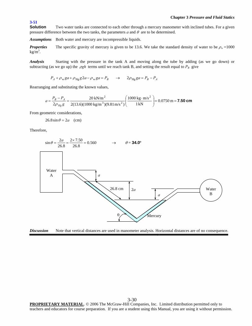
3-51 Solution Two water tanks are connected to each other through a mercury manometer with inclined tubes. For a given pressure difference between the two tanks, the parameters a and θ are to be determined.
Assumptions Both water and mercury are incompressible liquids.
Properties The specific gravity of mercury is given to be 13.6. We take the standard density of water to be ρw =1000 kg/m3.
Analysis Starting with the pressure in the tank A and moving along the tube by adding (as we go down) or subtracting (as we go up) the ghρ terms until we reach tank B, and setting the result equal to PB give
BA PgaaggaP =−++ wHgw 2 ρρρ → AB PPga −=Hg2ρ
Rearranging and substituting the known values,
cm 7.50 m 0750.0 kN1
m/s kg1000)m/s (9.81) kg/m002(13.6)(10
kN/m202
2
23
2==⎟⎟
⎠
⎞⎜⎜⎝
⎛ ⋅=
−=
gPP
aHg
AB
ρ
From geometric considerations,
a2sin8.26 =θ (cm)
Therefore,
560.08.2650.72
8.262sin =
×==
aθ → θ = 34.0°
Discussion Note that vertical distances are used in manometer analysis. Horizontal distances are of no consequence.
Mercury
Water A
Water B a
a
θ
2a 26.8 cm
Chapter 3 Pressure and Fluid Statics
PROPRIETARY MATERIAL. © 2006 The McGraw-Hill Companies, Inc. Limited distribution permitted only to teachers and educators for course preparation. If you are a student using this Manual, you are using it without permission.
3-31
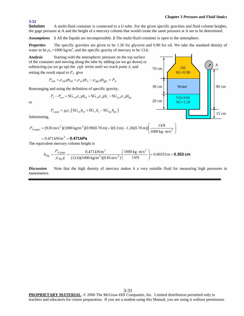
3-52 Solution A multi-fluid container is connected to a U-tube. For the given specific gravities and fluid column heights, the gage pressure at A and the height of a mercury column that would create the same pressure at A are to be determined.
Assumptions 1 All the liquids are incompressible. 2 The multi-fluid container is open to the atmosphere.
Properties The specific gravities are given to be 1.26 for glycerin and 0.90 for oil. We take the standard density of water to be ρw =1000 kg/m3, and the specific gravity of mercury to be 13.6.
Analysis Starting with the atmospheric pressure on the top surface of the container and moving along the tube by adding (as we go down) or subtracting (as we go up) the ghρ terms until we reach point A, and setting the result equal to PA give
Awatm PghghghP =−++ glyglywoiloil ρρρ
Rearranging and using the definition of specific gravity,
oil glySG SG SGA atm oil w w w w gly wP P gh gh ghρ ρ ρ− = + − or
( )gage oil oil gly glySG SG SGA, w w wP g h h hρ= + − Substituting,
kPa 0.471==
⎟⎟⎠
⎞⎜⎜⎝
⎛
⋅−+=
2
232
,
kN/m471.0
m/s kg1000 kN1m)] 70.0(26.1m) 3.0(1m) 70.0(90.0)[ kg/m)(1000m/s (9.81gageAP
The equivalent mercury column height is
cm 0.353 m 00353.0 kN1
m/s kg1000)m/s (9.81) kg/m0(13.6)(100
kN/m0.471 2
23
2, ==⎟⎟
⎠
⎞⎜⎜⎝
⎛ ⋅==
gP
hHg
gageAHg ρ
Discussion Note that the high density of mercury makes it a very suitable fluid for measuring high pressures in manometers.
A
90 cm
70 cm
30 cm
15 cm
Glycerin SG=1.26
Oil SG=0.90
Water
20 cm
Chapter 3 Pressure and Fluid Statics
PROPRIETARY MATERIAL. © 2006 The McGraw-Hill Companies, Inc. Limited distribution permitted only to teachers and educators for course preparation. If you are a student using this Manual, you are using it without permission.
3-32
Fluid Statics: Hydrostatic Forces on Plane and Curved Surfaces
3-53C Solution We are to define resultant force and center of pressure. Analysis The resultant hydrostatic force acting on a submerged surface is the resultant of the pressure forces acting on the surface. The point of application of this resultant force is called the center of pressure. Discussion The center of pressure is generally not at the center of the body, due to hydrostatic pressure variation.
3-54C Solution We are to examine a claim about hydrostatic force. Analysis Yes, because the magnitude of the resultant force acting on a plane surface of a completely submerged body in a homogeneous fluid is equal to the product of the pressure PC at the centroid of the surface and the area A of the surface. The pressure at the centroid of the surface is CC ghPP ρ+= 0 where Ch is the vertical distance of the centroid from the free surface of the liquid. Discussion We have assumed that we also know the pressure at the liquid surface.
3-55C Solution We are to consider the effect of plate rotation on the hydrostatic force on the plate surface. Analysis There will be no change on the hydrostatic force acting on the top surface of this submerged horizontal flat plate as a result of this rotation since the magnitude of the resultant force acting on a plane surface of a completely submerged body in a homogeneous fluid is equal to the product of the pressure PC at the centroid of the surface and the area A of the surface. Discussion If the rotation were not around the centroid, there would be a change in the force.
3-56C Solution We are to explain why dams are bigger at the bottom than at the top. Analysis Dams are built much thicker at the bottom because the pressure force increases with depth, and the bottom part of dams are subjected to largest forces. Discussion Dam construction requires an enormous amount of concrete, so tapering the dam in this way saves a lot of concrete, and therefore a lot of money.
3-57C Solution We are to explain how to determine the horizontal component of hydrostatic force on a curved surface. Analysis The horizontal component of the hydrostatic force acting on a curved surface is equal (in both magnitude and the line of action) to the hydrostatic force acting on the vertical projection of the curved surface. Discussion We could also integrate pressure along the surface, but the method discussed here is much simpler and yields the same answer.
Chapter 3 Pressure and Fluid Statics
PROPRIETARY MATERIAL. © 2006 The McGraw-Hill Companies, Inc. Limited distribution permitted only to teachers and educators for course preparation. If you are a student using this Manual, you are using it without permission.
3-33
3-58C Solution We are to explain how to determine the vertical component of hydrostatic force on a curved surface. Analysis The vertical component of the hydrostatic force acting on a curved surface is equal to the hydrostatic force acting on the horizontal projection of the curved surface, plus (minus, if acting in the opposite direction) the weight of the fluid block. Discussion We could also integrate pressure along the surface, but the method discussed here is much simpler and yields the same answer.
3-59C Solution We are to explain how to determine the line of action on a circular surface. Analysis The resultant hydrostatic force acting on a circular surface always passes through the center of the circle since the pressure forces are normal to the surface, and all lines normal to the surface of a circle pass through the center of the circle. Thus the pressure forces form a concurrent force system at the center, which can be reduced to a single equivalent force at that point. If the magnitudes of the horizontal and vertical components of the resultant hydrostatic force are known, the tangent of the angle the resultant hydrostatic force makes with the horizontal is HV FF /tan =α . Discussion This fact makes analysis of circular-shaped surfaces simple. There is no corresponding simplification for shapes other than circular, unfortunately.
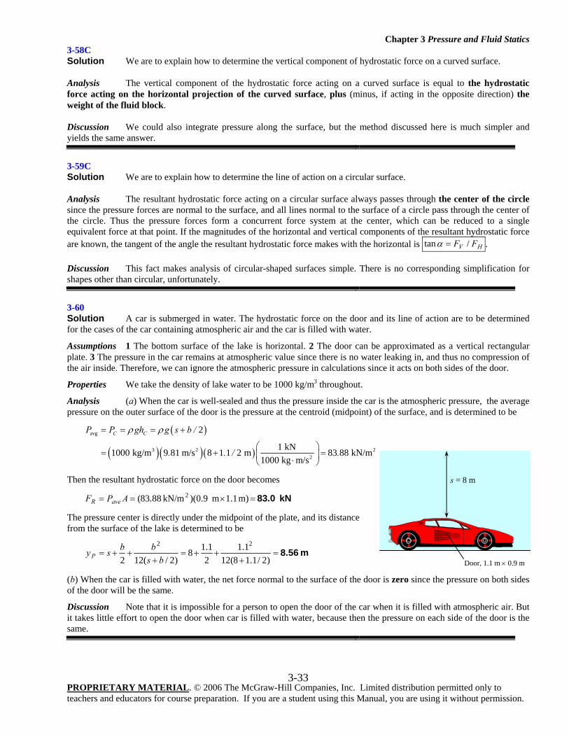
3-60 Solution A car is submerged in water. The hydrostatic force on the door and its line of action are to be determined for the cases of the car containing atmospheric air and the car is filled with water.
Assumptions 1 The bottom surface of the lake is horizontal. 2 The door can be approximated as a vertical rectangular plate. 3 The pressure in the car remains at atmospheric value since there is no water leaking in, and thus no compression of the air inside. Therefore, we can ignore the atmospheric pressure in calculations since it acts on both sides of the door.
Properties We take the density of lake water to be 1000 kg/m3 throughout.
Analysis (a) When the car is well-sealed and thus the pressure inside the car is the atmospheric pressure, the average pressure on the outer surface of the door is the pressure at the centroid (midpoint) of the surface, and is determined to be
( )
( )( )( )
avg
3 2 22
2
1 kN1000 kg/m 9 81 m/s 8 1 1 2 m 83 88 kN/m1000 kg m/s
C CP P gh g s b /
. . / .
ρ ρ= = = +
⎛ ⎞= + =⎜ ⎟⋅⎝ ⎠
Then the resultant hydrostatic force on the door becomes
kN 83.0 =×== m) 1.1m 9.0)(kN/m 88.83( 2APF aveR
The pressure center is directly under the midpoint of the plate, and its distance from the surface of the lake is determined to be
m 8.56=+
++=+
++=)2/1.18(12
1.121.18
)2/(122
22
bsbbsyP
(b) When the car is filled with water, the net force normal to the surface of the door is zero since the pressure on both sides of the door will be the same.
Discussion Note that it is impossible for a person to open the door of the car when it is filled with atmospheric air. But it takes little effort to open the door when car is filled with water, because then the pressure on each side of the door is the same.
s = 8 m
Door, 1.1 m × 0.9 m
Chapter 3 Pressure and Fluid Statics
PROPRIETARY MATERIAL. © 2006 The McGraw-Hill Companies, Inc. Limited distribution permitted only to teachers and educators for course preparation. If you are a student using this Manual, you are using it without permission.
3-34
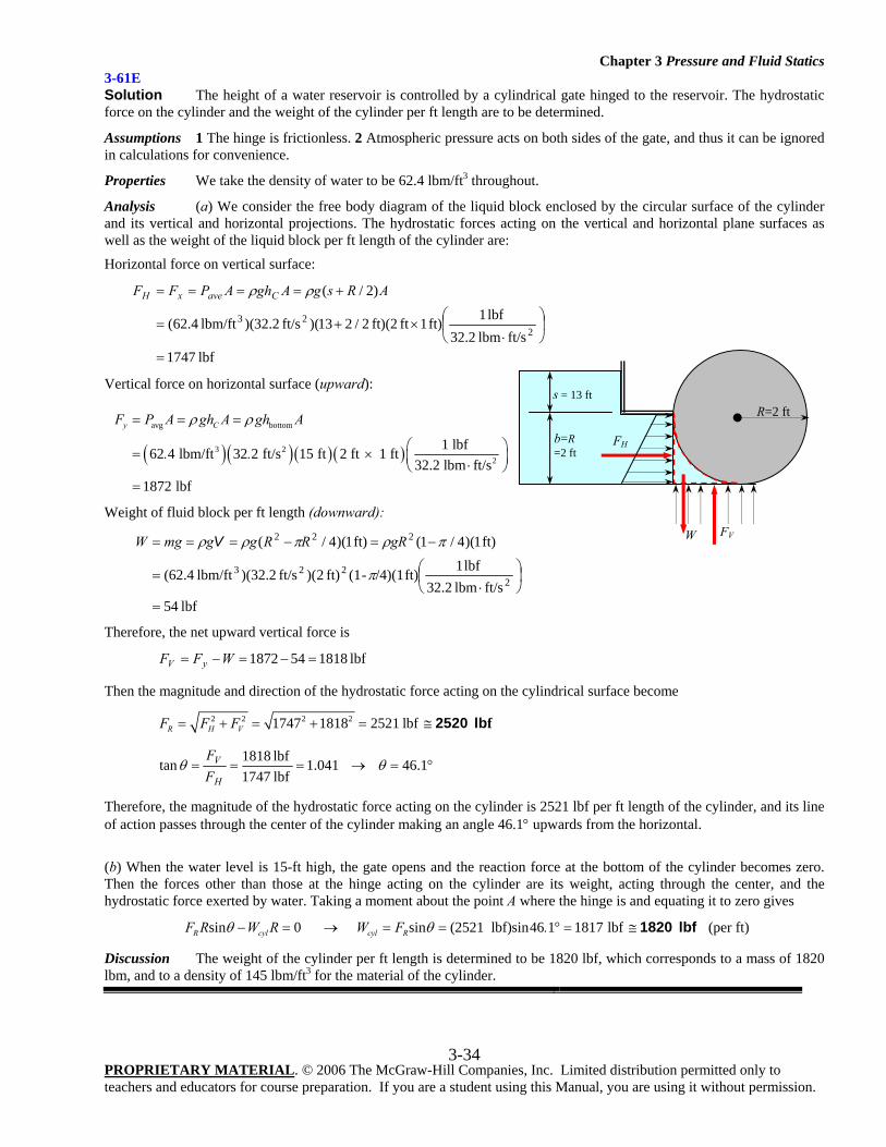
3-61E Solution The height of a water reservoir is controlled by a cylindrical gate hinged to the reservoir. The hydrostatic force on the cylinder and the weight of the cylinder per ft length are to be determined.
Assumptions 1 The hinge is frictionless. 2 Atmospheric pressure acts on both sides of the gate, and thus it can be ignored in calculations for convenience.
Properties We take the density of water to be 62.4 lbm/ft3 throughout.
Analysis (a) We consider the free body diagram of the liquid block enclosed by the circular surface of the cylinder and its vertical and horizontal projections. The hydrostatic forces acting on the vertical and horizontal plane surfaces as well as the weight of the liquid block per ft length of the cylinder are:
Horizontal force on vertical surface:
lbf 1747ft/slbm 32.2
lbf 1ft) 1 ft ft)(2 2/213)(ft/s 2.32)(lbm/ft 4.62(
)2/(
223
=
⎟⎠
⎞⎜⎝
⎛
⋅×+=
+==== ARsgAghAPFF CavexH ρρ
Vertical force on horizontal surface (upward):
( )( ) ( )( )
avg bottom
3 22
1 lbf62 4 lbm/ft 32 2 ft/s 15 ft 2 ft 1 ft32.2 lbm ft/s
1872 lbf
y CF P A gh A gh A
. .
ρ ρ= = =
⎛ ⎞= × ⎜ ⎟⋅⎝ ⎠=
Weight of fluid block per ft length (downward):
lbf 54ft/slbm 32.2
lbf 1ft) /4)(1-(1ft) 2)(ft/s 2.32)(lbm/ft 4.62(
ft) 1)(4/1(ft) 1)(4/(
2223
222
=
⎟⎠⎞
⎜⎝⎛
⋅=
−=−===
π
πρπρρ gRRRggmgW V
Therefore, the net upward vertical force is
lbf 1818541872 =−=−= WFF yV
Then the magnitude and direction of the hydrostatic force acting on the cylindrical surface become
2 2 2 21747 1818 2521 lbfR H VF F F= + = + = ≅ f2520 lb
°=→=== 1.46 041.1lbf 1747lbf 1818tan θθ
H
V
FF
Therefore, the magnitude of the hydrostatic force acting on the cylinder is 2521 lbf per ft length of the cylinder, and its line of action passes through the center of the cylinder making an angle 46.1° upwards from the horizontal.
(b) When the water level is 15-ft high, the gate opens and the reaction force at the bottom of the cylinder becomes zero. Then the forces other than those at the hinge acting on the cylinder are its weight, acting through the center, and the hydrostatic force exerted by water. Taking a moment about the point A where the hinge is and equating it to zero gives
sin 0 sin (2521 lbf)sin46 1 1817 lbfR cyl cyl RF R W R W F .θ θ− = → = = ° = ≅ 1820 lbf (per ft)
Discussion The weight of the cylinder per ft length is determined to be 1820 lbf, which corresponds to a mass of 1820 lbm, and to a density of 145 lbm/ft3 for the material of the cylinder.
FH
FV W
R=2 ft
s = 13 ft
b=R =2 ft
Chapter 3 Pressure and Fluid Statics
PROPRIETARY MATERIAL. © 2006 The McGraw-Hill Companies, Inc. Limited distribution permitted only to teachers and educators for course preparation. If you are a student using this Manual, you are using it without permission.
3-35
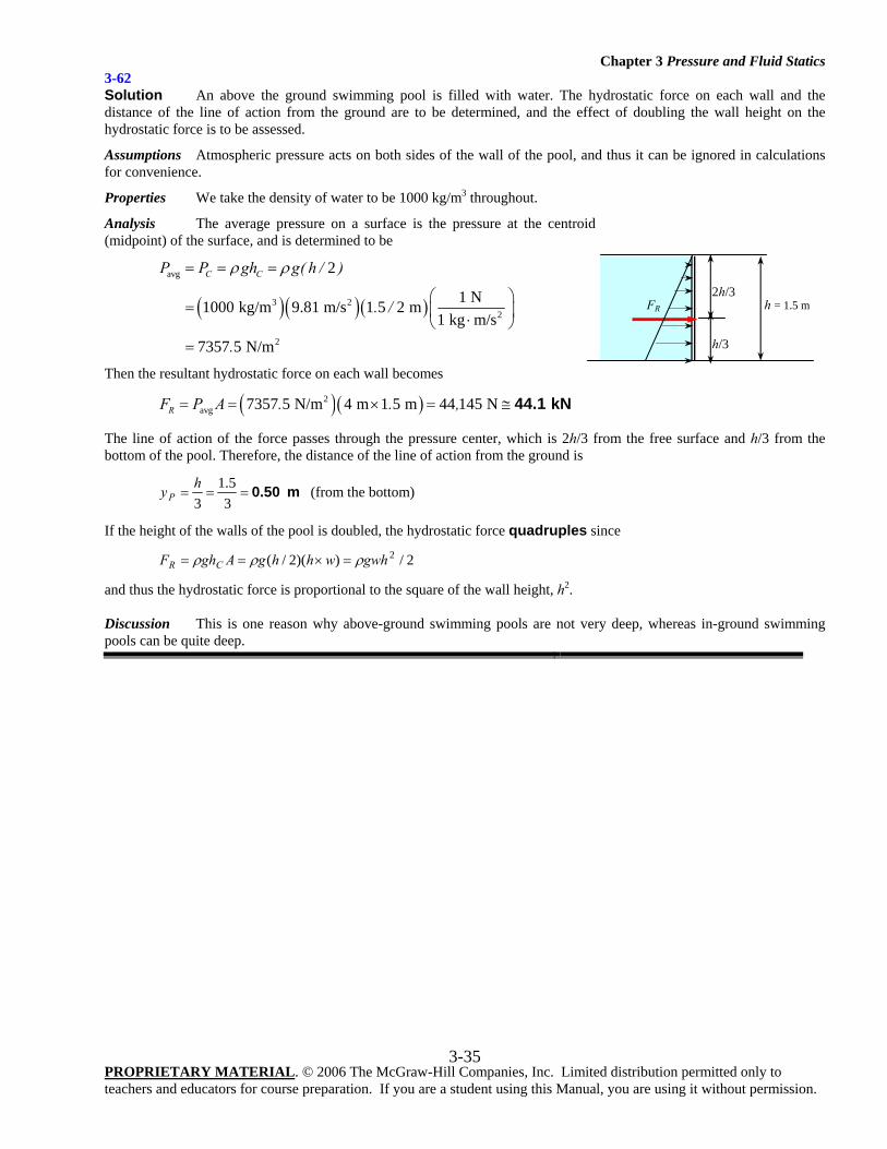
3-62 Solution An above the ground swimming pool is filled with water. The hydrostatic force on each wall and the distance of the line of action from the ground are to be determined, and the effect of doubling the wall height on the hydrostatic force is to be assessed.
Assumptions Atmospheric pressure acts on both sides of the wall of the pool, and thus it can be ignored in calculations for convenience.
Properties We take the density of water to be 1000 kg/m3 throughout.
Analysis The average pressure on a surface is the pressure at the centroid (midpoint) of the surface, and is determined to be
( )( )( )
avg
3 22
2
2
1 N1000 kg/m 9.81 m/s 1 5 2 m1 kg m/s
7357 5 N/m
C CP P gh g( h / )
. /
.
ρ ρ= = =
⎛ ⎞= ⎜ ⎟⋅⎝ ⎠=
Then the resultant hydrostatic force on each wall becomes
( )( )2avg 7357 5 N/m 4 m 1 5 m 44 145 NRF P A . . ,= = × = ≅ 44.1 kN
The line of action of the force passes through the pressure center, which is 2h/3 from the free surface and h/3 from the bottom of the pool. Therefore, the distance of the line of action from the ground is
m 0.50===35.1
3hyP (from the bottom)
If the height of the walls of the pool is doubled, the hydrostatic force quadruples since
2/))(2/( 2gwhwhhgAghF CR ρρρ =×==
and thus the hydrostatic force is proportional to the square of the wall height, h2. Discussion This is one reason why above-ground swimming pools are not very deep, whereas in-ground swimming pools can be quite deep.
FR h = 1.5 m
2h/3
h/3
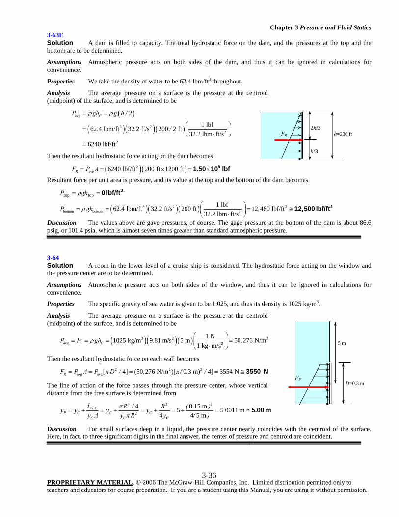
Chapter 3 Pressure and Fluid Statics
PROPRIETARY MATERIAL. © 2006 The McGraw-Hill Companies, Inc. Limited distribution permitted only to teachers and educators for course preparation. If you are a student using this Manual, you are using it without permission.
3-36
3-63E Solution A dam is filled to capacity. The total hydrostatic force on the dam, and the pressures at the top and the bottom are to be determined.
Assumptions Atmospheric pressure acts on both sides of the dam, and thus it can be ignored in calculations for convenience.
Properties We take the density of water to be 62.4 lbm/ft3 throughout.
Analysis The average pressure on a surface is the pressure at the centroid (midpoint) of the surface, and is determined to be
( )
( )( )( )
avg
3 22
2
2
1 lbf62 4 lbm/ft 32 2 ft/s 200 2 ft32.2 lbm ft/s
6240 lbf/ft
CP gh g h /
. . /
ρ ρ= =
⎛ ⎞= ⎜ ⎟⋅⎝ ⎠=
Then the resultant hydrostatic force acting on the dam becomes
( )( )2ave 6240 lbf/ft 200 ft 1200 ftRF P A= = × = × 91.50 10 lbf
Resultant force per unit area is pressure, and its value at the top and the bottom of the dam becomes 2lbf/ft 0== toptop ghP ρ
( )( ) ( )3 2 2bottom bottom 2
1 lbf62 4 lbm/ft 32 2 ft/s 200 ft 12 480 lbf/ft32.2 lbm ft/s
P gh . . ,ρ ⎛ ⎞= = = ≅⎜ ⎟⋅⎝ ⎠212,500 lbf/ft
Discussion The values above are gave pressures, of course. The gage pressure at the bottom of the dam is about 86.6 psig, or 101.4 psia, which is almost seven times greater than standard atmospheric pressure.
3-64 Solution A room in the lower level of a cruise ship is considered. The hydrostatic force acting on the window and the pressure center are to be determined.
Assumptions Atmospheric pressure acts on both sides of the window, and thus it can be ignored in calculations for convenience.
Properties The specific gravity of sea water is given to be 1.025, and thus its density is 1025 kg/m3.
Analysis The average pressure on a surface is the pressure at the centroid (midpoint) of the surface, and is determined to be
( )( )( )3 2 22
1 N1025 kg/m 9 81 m/s 5 m 50 276 N/m1 kg m/savg C CP P gh . ,ρ
⎛ ⎞= = = =⎜ ⎟⋅⎝ ⎠
Then the resultant hydrostatic force on each wall becomes 2 2 2
avg avg[ 4] (50 276 N/m )[ 0 3 m) 4] 3554 NRF P A P D / , ( . /π π= = = = ≅ 3550 N
The line of action of the force passes through the pressure center, whose vertical distance from the free surface is determined from
4 2 2
2
4 0.15 m5 5 0011 m4 4 5 m
xx ,CP C C C
C CC
I R / R ( )y y y y .y A y ( )y R
ππ
= + = + = + = + = ≅ 5.00 m
Discussion For small surfaces deep in a liquid, the pressure center nearly coincides with the centroid of the surface. Here, in fact, to three significant digits in the final answer, the center of pressure and centroid are coincident.
FR h=200 ft
2h/3
h/3
FR
5 m
D=0.3 m
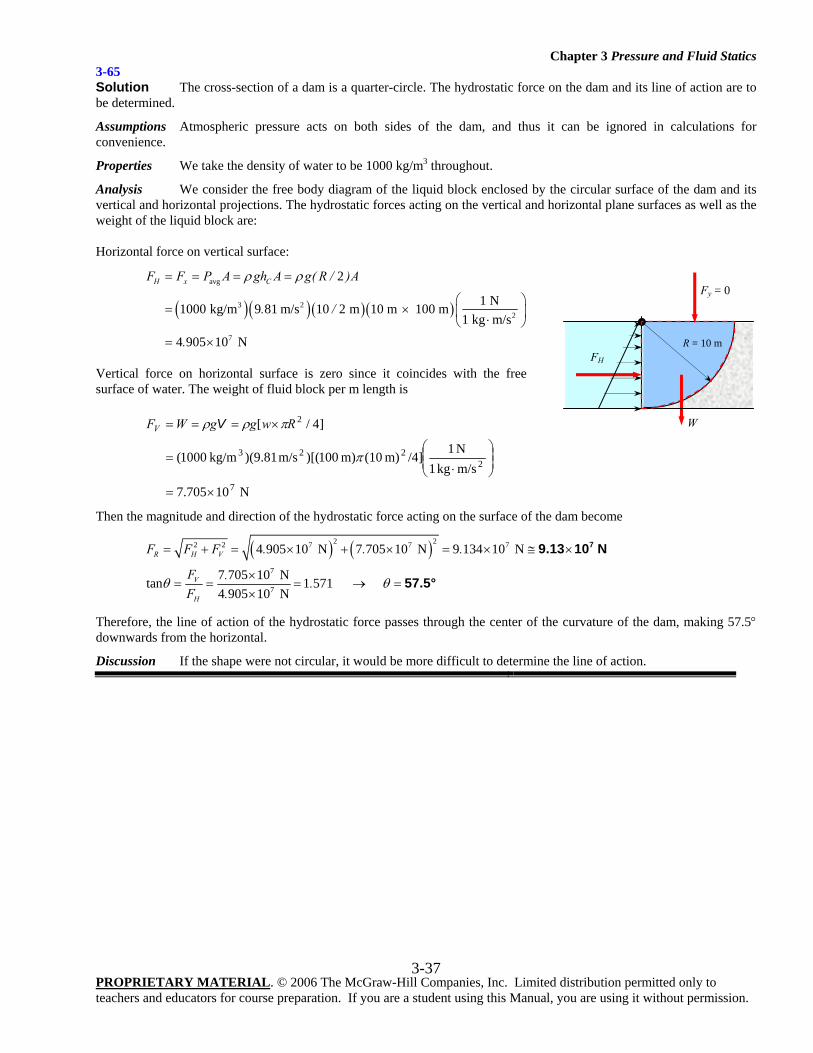
Chapter 3 Pressure and Fluid Statics
PROPRIETARY MATERIAL. © 2006 The McGraw-Hill Companies, Inc. Limited distribution permitted only to teachers and educators for course preparation. If you are a student using this Manual, you are using it without permission.
3-37
3-65 Solution The cross-section of a dam is a quarter-circle. The hydrostatic force on the dam and its line of action are to be determined.
Assumptions Atmospheric pressure acts on both sides of the dam, and thus it can be ignored in calculations for convenience.
Properties We take the density of water to be 1000 kg/m3 throughout.
Analysis We consider the free body diagram of the liquid block enclosed by the circular surface of the dam and its vertical and horizontal projections. The hydrostatic forces acting on the vertical and horizontal plane surfaces as well as the weight of the liquid block are: Horizontal force on vertical surface:
( )( )( )( )
avg
3 22
7
2
1 N1000 kg/m 9 81 m/s 10 2 m 10 m 100 m1 kg m/s
4 905 10 N
H x CF F P A gh A g( R / )A
. /
.
ρ ρ= = = =
⎛ ⎞= × ⎜ ⎟⋅⎝ ⎠= ×
Vertical force on horizontal surface is zero since it coincides with the free surface of water. The weight of fluid block per m length is
N 10705.7
m/s kg1N 1/4]m) (10m) 100)[(m/s 81.9)( kg/m1000(
]4/[
7
2223
2
×=
⎟⎟⎠
⎞⎜⎜⎝
⎛
⋅=
×===
π
πρρ RwggWFV V
Then the magnitude and direction of the hydrostatic force acting on the surface of the dam become
( ) ( )2 22 2 7 7 7
7
7
4 905 10 N 7 705 10 N 9 134 10 N
7 705 10 Ntan 1 571 4 905 10 N
R H V
V
H
F F F . . .
F . .F .
θ θ
= + = × + × = × ≅ ×
×= = = → =
×
79.13 10 N
57.5°
Therefore, the line of action of the hydrostatic force passes through the center of the curvature of the dam, making 57.5° downwards from the horizontal.
Discussion If the shape were not circular, it would be more difficult to determine the line of action.
R = 10 m
FH
Fy = 0
W
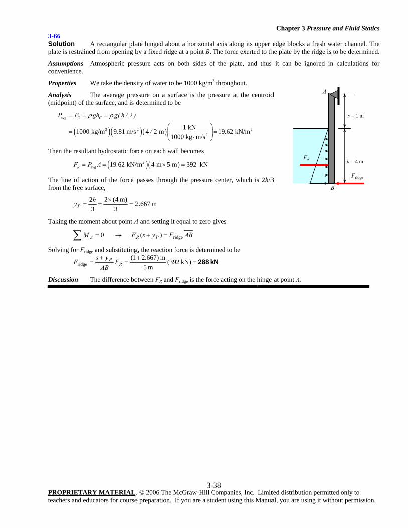
Chapter 3 Pressure and Fluid Statics
PROPRIETARY MATERIAL. © 2006 The McGraw-Hill Companies, Inc. Limited distribution permitted only to teachers and educators for course preparation. If you are a student using this Manual, you are using it without permission.
3-38
3-66 Solution A rectangular plate hinged about a horizontal axis along its upper edge blocks a fresh water channel. The plate is restrained from opening by a fixed ridge at a point B. The force exerted to the plate by the ridge is to be determined.
Assumptions Atmospheric pressure acts on both sides of the plate, and thus it can be ignored in calculations for convenience.
Properties We take the density of water to be 1000 kg/m3 throughout.
Analysis The average pressure on a surface is the pressure at the centroid (midpoint) of the surface, and is determined to be
( )( ) ( )
avg
3 2 22
2
1 kN1000 kg/m 9 81 m/s 4 2 m 19 62 kN/m1000 kg m/s
C CP P gh g( h / )
. / .
ρ ρ= = =
⎛ ⎞= =⎜ ⎟⋅⎝ ⎠
Then the resultant hydrostatic force on each wall becomes
( )( )2avg 19 62 kN/m 4 m 5 m 392 kNRF P A .= = × =
The line of action of the force passes through the pressure center, which is 2h/3 from the free surface,
m 2.6673
m) 4(23
2=
×==
hyP
Taking the moment about point A and setting it equal to zero gives
ABFysFM PRA ridge)( 0 =+→=∑
Solving for Fridge and substituting, the reaction force is determined to be
kN 288=+
=+
= kN)392(m 5
m )667.21(ridge R
P FAB
ysF
Discussion The difference between FR and Fridge is the force acting on the hinge at point A.
FR
Fridge
s = 1 m
h = 4 m
A
B
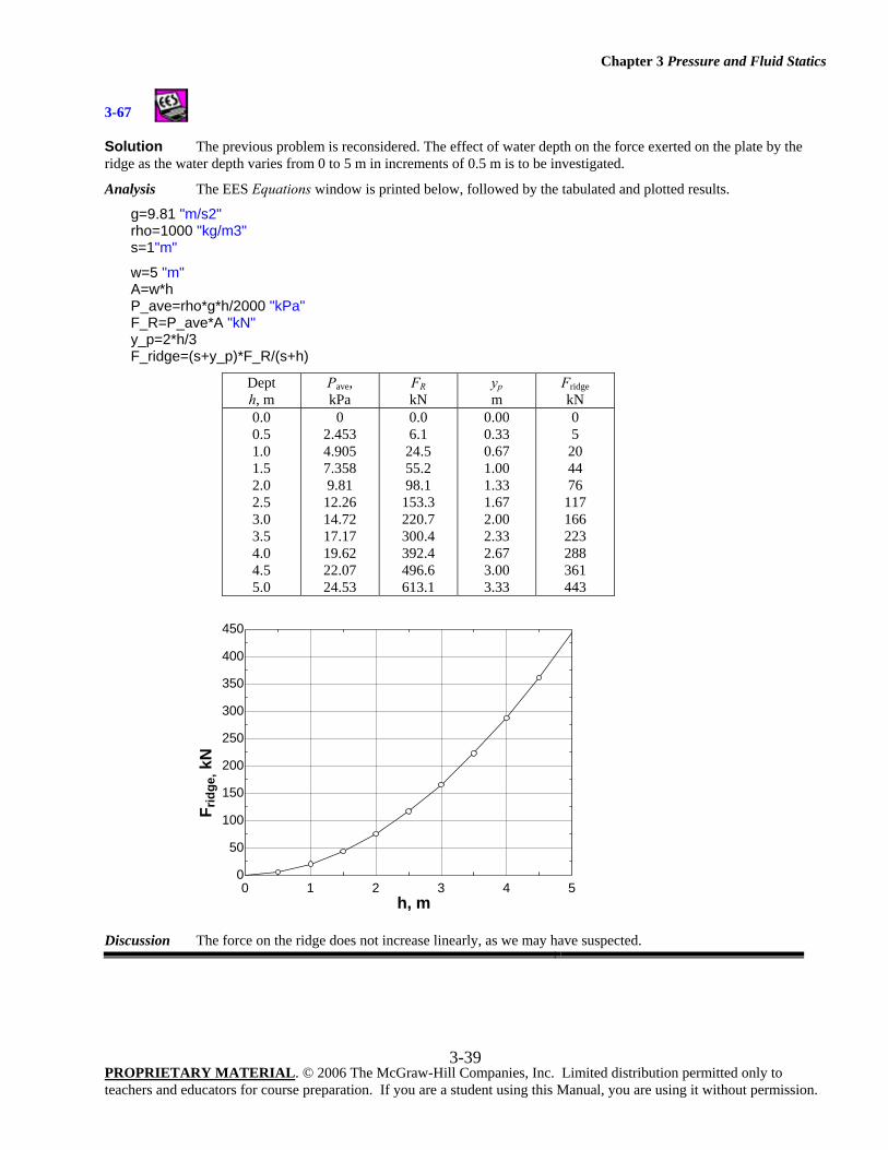
Chapter 3 Pressure and Fluid Statics
PROPRIETARY MATERIAL. © 2006 The McGraw-Hill Companies, Inc. Limited distribution permitted only to teachers and educators for course preparation. If you are a student using this Manual, you are using it without permission.
3-39
3-67
Solution The previous problem is reconsidered. The effect of water depth on the force exerted on the plate by the ridge as the water depth varies from 0 to 5 m in increments of 0.5 m is to be investigated.
Analysis The EES Equations window is printed below, followed by the tabulated and plotted results.
g=9.81 "m/s2" rho=1000 "kg/m3" s=1"m"
w=5 "m" A=w*h P_ave=rho*g*h/2000 "kPa" F_R=P_ave*A "kN" y_p=2*h/3 F_ridge=(s+y_p)*F_R/(s+h)
Dept h, m
Pave, kPa
FR kN
yp m
Fridge kN
0.0 0.5 1.0 1.5 2.0 2.5 3.0 3.5 4.0 4.5 5.0
0 2.453 4.905 7.358 9.81
12.26 14.72 17.17 19.62 22.07 24.53
0.0 6.1
24.5 55.2 98.1
153.3 220.7 300.4 392.4 496.6 613.1
0.00 0.33 0.67 1.00 1.33 1.67 2.00 2.33 2.67 3.00 3.33
0 5
20 44 76
117 166 223 288 361 443
Discussion The force on the ridge does not increase linearly, as we may have suspected.
0 1 2 3 4 50
50
100
150
200
250
300
350
400
450
h, m
F rid
ge, k
N
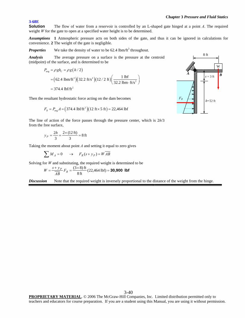
Chapter 3 Pressure and Fluid Statics
PROPRIETARY MATERIAL. © 2006 The McGraw-Hill Companies, Inc. Limited distribution permitted only to teachers and educators for course preparation. If you are a student using this Manual, you are using it without permission.
3-40
3-68E Solution The flow of water from a reservoir is controlled by an L-shaped gate hinged at a point A. The required weight W for the gate to open at a specified water height is to be determined.
Assumptions 1 Atmospheric pressure acts on both sides of the gate, and thus it can be ignored in calculations for convenience. 2 The weight of the gate is negligible.
Properties We take the density of water to be 62.4 lbm/ft3 throughout.
Analysis The average pressure on a surface is the pressure at the centroid (midpoint) of the surface, and is determined to be
( )
( )( ) ( )
avg
3 22
2
2
1 lbf62 4 lbm/ft 32 2 ft/s 12 2 ft32.2 lbm ft/s
374 4 lbf/ft
CP gh g h /
. . /
.
ρ ρ= =
⎛ ⎞= ⎜ ⎟⋅⎝ ⎠=
Then the resultant hydrostatic force acting on the dam becomes
( )( )2avg 374 4 lbf/ft 12 ft 5 ft 22,464 lbfRF P A .= = × =
The line of action of the force passes through the pressure center, which is 2h/3 from the free surface,
ft 83
ft) 12(23
2=
×==
hyP
Taking the moment about point A and setting it equal to zero gives
ABWysFM PRA =+→=∑ )( 0
Solving for W and substituting, the required weight is determined to be
lbf 30,900=+
=+
= lbf) 464,22(ft 8
ft )83(R
P FAB
ysW
Discussion Note that the required weight is inversely proportional to the distance of the weight from the hinge.
B
FR
W
s = 3 ft
h=12 ft
A
8 ft
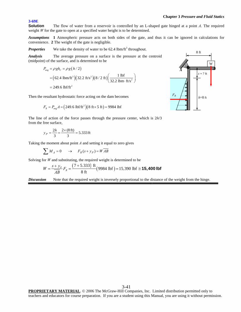
Chapter 3 Pressure and Fluid Statics
PROPRIETARY MATERIAL. © 2006 The McGraw-Hill Companies, Inc. Limited distribution permitted only to teachers and educators for course preparation. If you are a student using this Manual, you are using it without permission.
3-41
3-69E Solution The flow of water from a reservoir is controlled by an L-shaped gate hinged at a point A. The required weight W for the gate to open at a specified water height is to be determined.
Assumptions 1 Atmospheric pressure acts on both sides of the gate, and thus it can be ignored in calculations for convenience. 2 The weight of the gate is negligible.
Properties We take the density of water to be 62.4 lbm/ft3 throughout.
Analysis The average pressure on a surface is the pressure at the centroid (midpoint) of the surface, and is determined to be
( )
( ) ( )( )
avg
3 22
2
2
1 lbf62 4 lbm/ft 32 2 ft/s 8 2 ft32.2 lbm ft/s
249 6 lbf/ft
CP gh g h /
. . /
.
ρ ρ= =
⎛ ⎞= ⎜ ⎟⋅⎝ ⎠=
Then the resultant hydrostatic force acting on the dam becomes
( )( )2avg 249 6 lbf/ft 8 ft 5 ft 9984 lbfRF P A .= = × =
The line of action of the force passes through the pressure center, which is 2h/3 from the free surface,
ft 333.53
ft) 8(23
2=
×==
hyP
Taking the moment about point A and setting it equal to zero gives
ABWysFM PRA =+→=∑ )( 0
Solving for W and substituting, the required weight is determined to be ( ) ( )7 5 333 ft
9984 lbf 15 390 lbf8 ft
PR
.s yW F ,AB
++= = = ≅ 15,400 lbf
Discussion Note that the required weight is inversely proportional to the distance of the weight from the hinge.
FR
W
s = 7 ft
h=8 ft
A B
8 ft
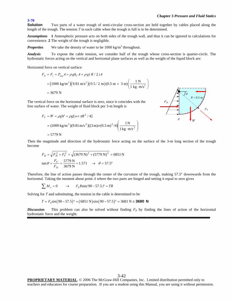
Chapter 3 Pressure and Fluid Statics
PROPRIETARY MATERIAL. © 2006 The McGraw-Hill Companies, Inc. Limited distribution permitted only to teachers and educators for course preparation. If you are a student using this Manual, you are using it without permission.
3-42
3-70 Solution Two parts of a water trough of semi-circular cross-section are held together by cables placed along the length of the trough. The tension T in each cable when the trough is full is to be determined.
Assumptions 1 Atmospheric pressure acts on both sides of the trough wall, and thus it can be ignored in calculations for convenience. 2 The weight of the trough is negligible.
Properties We take the density of water to be 1000 kg/m3 throughout.
Analysis To expose the cable tension, we consider half of the trough whose cross-section is quarter-circle. The hydrostatic forces acting on the vertical and horizontal plane surfaces as well as the weight of the liquid block are: Horizontal force on vertical surface:
( )( )( )
avg
3 22
2
1 N1000 kg/m 9 81 m/s 0 5 2 m (0.5 m 3 m)1 kg m/s
3679 N
H x CF F P A gh A g( R / )A
. . /
ρ ρ= = = =
⎛ ⎞= × ⎜ ⎟⋅⎝ ⎠=
The vertical force on the horizontal surface is zero, since it coincides with the free surface of water. The weight of fluid block per 3-m length is
N 5779m/s kg1N 1/4]m) (0.5m) 3)[(m/s 81.9)( kg/m1000(
]4/[
2223
2
=
⎟⎟⎠
⎞⎜⎜⎝
⎛
⋅=
×===
π
πρρ RwggWFV V
Then the magnitude and direction of the hydrostatic force acting on the surface of the 3-m long section of the trough become
°=→===
=+=+=
57.5 571.1N 3679N 5779tan
N 6851N) 5779(N) 3679( 2222
θθH
V
VHR
FF
FFF
Therefore, the line of action passes through the center of the curvature of the trough, making 57.5° downwards from the horizontal. Taking the moment about point A where the two parts are hinged and setting it equal to zero gives
0 sin 90 57 5A RM F R ( . ) TR= → − ° =∑
Solving for T and substituting, the tension in the cable is determined to be
( ) ( ) ( )sin 90 57 5 6851 N sin 90 57 5 3681 NRT F . .= − ° = − ° = ≅ 3680 N
Discussion This problem can also be solved without finding FR by finding the lines of action of the horizontal hydrostatic force and the weight.
R = 0.5 m
FH
T
W A
FR
θ
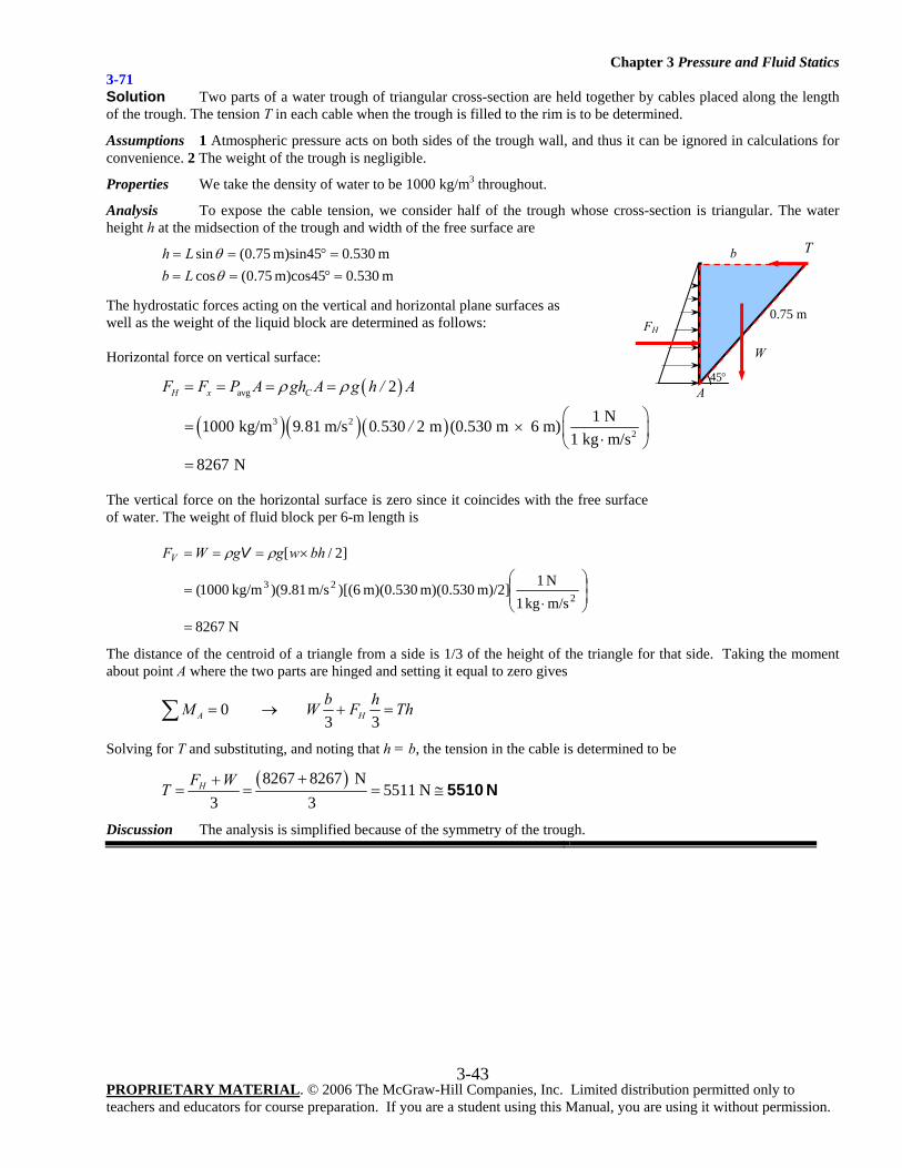
Chapter 3 Pressure and Fluid Statics
PROPRIETARY MATERIAL. © 2006 The McGraw-Hill Companies, Inc. Limited distribution permitted only to teachers and educators for course preparation. If you are a student using this Manual, you are using it without permission.
3-43
3-71 Solution Two parts of a water trough of triangular cross-section are held together by cables placed along the length of the trough. The tension T in each cable when the trough is filled to the rim is to be determined.
Assumptions 1 Atmospheric pressure acts on both sides of the trough wall, and thus it can be ignored in calculations for convenience. 2 The weight of the trough is negligible.
Properties We take the density of water to be 1000 kg/m3 throughout.
Analysis To expose the cable tension, we consider half of the trough whose cross-section is triangular. The water height h at the midsection of the trough and width of the free surface are
m 530.0m)cos45 75.0(cos m 530.0m)sin45 75.0(sin
=°===°==
θθ
LbLh
The hydrostatic forces acting on the vertical and horizontal plane surfaces as well as the weight of the liquid block are determined as follows: Horizontal force on vertical surface:
( )
( )( )( )
avg
3 22
2
1 N1000 kg/m 9 81 m/s 0 530 2 m (0.530 m 6 m)1 kg m/s
8267 N
H x CF F P A gh A g h / A
. . /
ρ ρ= = = =
⎛ ⎞= × ⎜ ⎟⋅⎝ ⎠=
The vertical force on the horizontal surface is zero since it coincides with the free surface of water. The weight of fluid block per 6-m length is
N 8267m/skg 1N 1m)/2] m)(0.530 m)(0.530 6)[(m/s 81.9)(kg/m 1000(
]2/[
223
=
⎟⎟⎠
⎞⎜⎜⎝
⎛
⋅=
×=== bhwggWFV ρρ V
The distance of the centroid of a triangle from a side is 1/3 of the height of the triangle for that side. Taking the moment about point A where the two parts are hinged and setting it equal to zero gives
0 3 3A Hb hM W F Th= → + =∑
Solving for T and substituting, and noting that h = b, the tension in the cable is determined to be
( )8267 8267 N5511 N
3 3HF WT
++= = = ≅ 5510 N
Discussion The analysis is simplified because of the symmetry of the trough.
FH
W
0.75 m
45°
T b
A
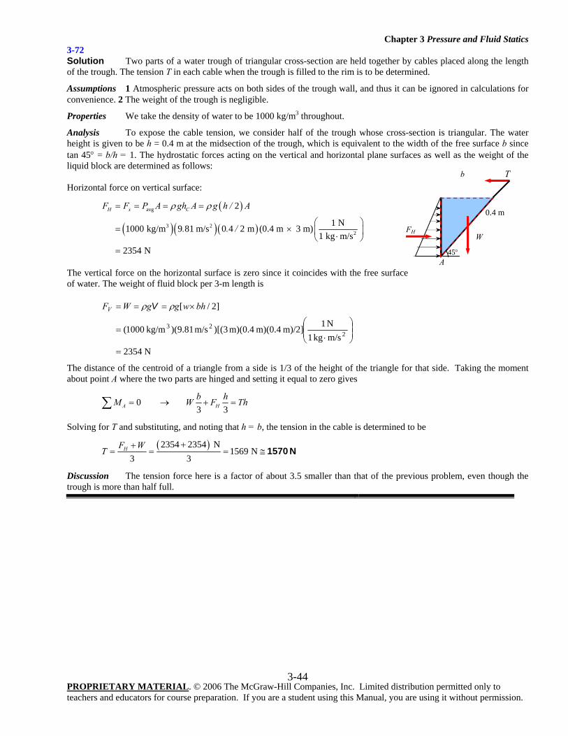
Chapter 3 Pressure and Fluid Statics
PROPRIETARY MATERIAL. © 2006 The McGraw-Hill Companies, Inc. Limited distribution permitted only to teachers and educators for course preparation. If you are a student using this Manual, you are using it without permission.
3-44
3-72 Solution Two parts of a water trough of triangular cross-section are held together by cables placed along the length of the trough. The tension T in each cable when the trough is filled to the rim is to be determined.
Assumptions 1 Atmospheric pressure acts on both sides of the trough wall, and thus it can be ignored in calculations for convenience. 2 The weight of the trough is negligible.
Properties We take the density of water to be 1000 kg/m3 throughout.
Analysis To expose the cable tension, we consider half of the trough whose cross-section is triangular. The water height is given to be h = 0.4 m at the midsection of the trough, which is equivalent to the width of the free surface b since tan 45° = b/h = 1. The hydrostatic forces acting on the vertical and horizontal plane surfaces as well as the weight of the liquid block are determined as follows: Horizontal force on vertical surface:
( )
( )( )( )
avg
3 22
2
1 N1000 kg/m 9 81 m/s 0 4 2 m (0.4 m 3 m)1 kg m/s
2354 N
H x CF F P A gh A g h / A
. . /
ρ ρ= = = =
⎛ ⎞= × ⎜ ⎟⋅⎝ ⎠=
The vertical force on the horizontal surface is zero since it coincides with the free surface of water. The weight of fluid block per 3-m length is
N 2354m/s kg1N 1m)/2] m)(0.4 m)(0.4 3)[(m/s 81.9)( kg/m1000(
]2/[
223
=
⎟⎟⎠
⎞⎜⎜⎝
⎛
⋅=
×=== bhwggWFV ρρ V
The distance of the centroid of a triangle from a side is 1/3 of the height of the triangle for that side. Taking the moment about point A where the two parts are hinged and setting it equal to zero gives
0 3 3A Hb hM W F Th= → + =∑
Solving for T and substituting, and noting that h = b, the tension in the cable is determined to be
( )2354 2354 N1569 N
3 3HF WT
++= = = ≅ 1570 N
Discussion The tension force here is a factor of about 3.5 smaller than that of the previous problem, even though the trough is more than half full.
FH W
0.4 m
45°
T b
A
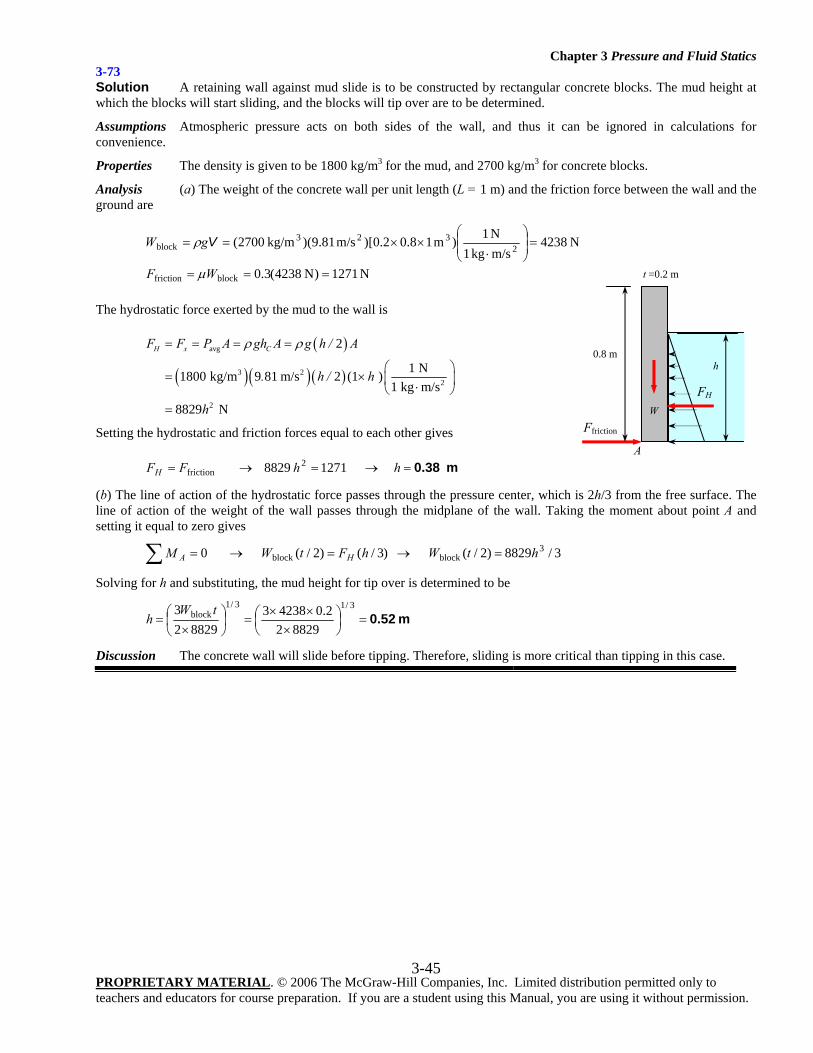
Chapter 3 Pressure and Fluid Statics
PROPRIETARY MATERIAL. © 2006 The McGraw-Hill Companies, Inc. Limited distribution permitted only to teachers and educators for course preparation. If you are a student using this Manual, you are using it without permission.
3-45
3-73 Solution A retaining wall against mud slide is to be constructed by rectangular concrete blocks. The mud height at which the blocks will start sliding, and the blocks will tip over are to be determined.
Assumptions Atmospheric pressure acts on both sides of the wall, and thus it can be ignored in calculations for convenience.
Properties The density is given to be 1800 kg/m3 for the mud, and 2700 kg/m3 for concrete blocks.
Analysis (a) The weight of the concrete wall per unit length (L = 1 m) and the friction force between the wall and the ground are
N 1271)N 4238(3.0
N 4238m/s kg1N 1)m 18.02.0)[m/s 81.9)( kg/m2700(
blockfriction
2323
block
===
=⎟⎟⎠
⎞⎜⎜⎝
⎛
⋅××==
WF
gW
μ
ρ V
The hydrostatic force exerted by the mud to the wall is
( )
( )( )( )
avg
3 22
2
2
1 N1800 kg/m 9 81 m/s 2 (1 )1 kg m/s
8829 N
H x CF F P A gh A g h / A
. h / h
h
ρ ρ= = = =
⎛ ⎞= × ⎜ ⎟⋅⎝ ⎠=
Setting the hydrostatic and friction forces equal to each other gives
m 0.38=→=→= hhFFH 1271 8829 2friction
(b) The line of action of the hydrostatic force passes through the pressure center, which is 2h/3 from the free surface. The line of action of the weight of the wall passes through the midplane of the wall. Taking the moment about point A and setting it equal to zero gives
3/8829)2/( )3/()2/( 0 3blockblock htWhFtWM HA =→=→=∑
Solving for h and substituting, the mud height for tip over is determined to be
m 0.52=⎟⎠⎞
⎜⎝⎛
×××
=⎟⎠⎞
⎜⎝⎛
×=
3/13/1block
882922.042383
882923 tW
h
Discussion The concrete wall will slide before tipping. Therefore, sliding is more critical than tipping in this case.
FH
Ffriction
0.8 m h
t =0.2 m
A
W
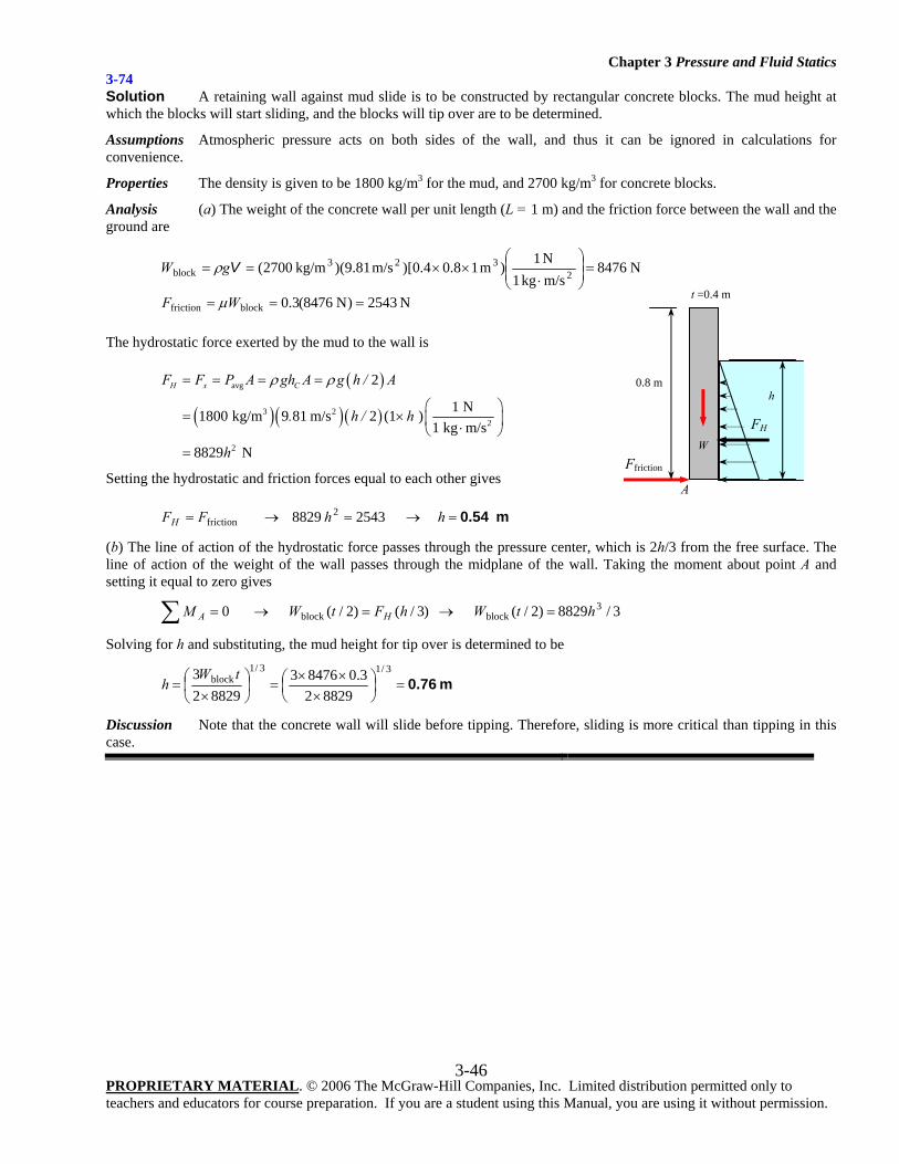
Chapter 3 Pressure and Fluid Statics
PROPRIETARY MATERIAL. © 2006 The McGraw-Hill Companies, Inc. Limited distribution permitted only to teachers and educators for course preparation. If you are a student using this Manual, you are using it without permission.
3-46
3-74 Solution A retaining wall against mud slide is to be constructed by rectangular concrete blocks. The mud height at which the blocks will start sliding, and the blocks will tip over are to be determined.
Assumptions Atmospheric pressure acts on both sides of the wall, and thus it can be ignored in calculations for convenience.
Properties The density is given to be 1800 kg/m3 for the mud, and 2700 kg/m3 for concrete blocks.
Analysis (a) The weight of the concrete wall per unit length (L = 1 m) and the friction force between the wall and the ground are
N 2543)N 8476(3.0
N 8476m/s kg1N 1)m 18.04.0)[m/s 81.9)( kg/m2700(
blockfriction
2323
block
===
=⎟⎟⎠
⎞⎜⎜⎝
⎛
⋅××==
WF
gW
μ
ρ V
The hydrostatic force exerted by the mud to the wall is
( )
( )( )( )
avg
3 22
2
2
1 N1800 kg/m 9 81 m/s 2 (1 )1 kg m/s
8829 N
H x CF F P A gh A g h / A
. h / h
h
ρ ρ= = = =
⎛ ⎞= × ⎜ ⎟⋅⎝ ⎠=
Setting the hydrostatic and friction forces equal to each other gives
m 0.54=→=→= hhFFH 2543 8829 2friction
(b) The line of action of the hydrostatic force passes through the pressure center, which is 2h/3 from the free surface. The line of action of the weight of the wall passes through the midplane of the wall. Taking the moment about point A and setting it equal to zero gives
3/8829)2/( )3/()2/( 0 3blockblock htWhFtWM HA =→=→=∑
Solving for h and substituting, the mud height for tip over is determined to be
m 0.76=⎟⎠⎞
⎜⎝⎛
×××
=⎟⎠⎞
⎜⎝⎛
×=
3/13/1block
882923.084763
882923 tW
h
Discussion Note that the concrete wall will slide before tipping. Therefore, sliding is more critical than tipping in this case.
FH
Ffriction
0.8 m h
t =0.4 m
A
W
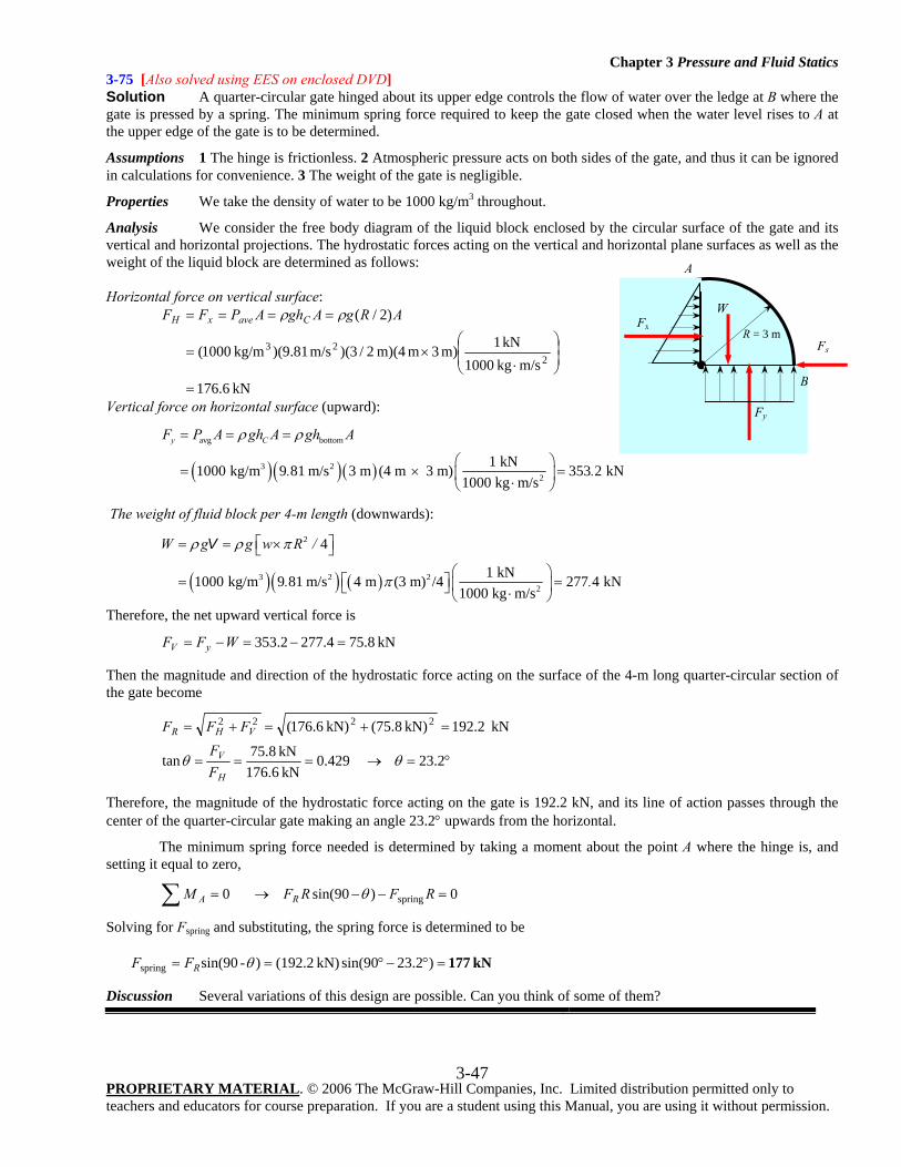
Chapter 3 Pressure and Fluid Statics
PROPRIETARY MATERIAL. © 2006 The McGraw-Hill Companies, Inc. Limited distribution permitted only to teachers and educators for course preparation. If you are a student using this Manual, you are using it without permission.
3-47
3-75 [Also solved using EES on enclosed DVD] Solution A quarter-circular gate hinged about its upper edge controls the flow of water over the ledge at B where the gate is pressed by a spring. The minimum spring force required to keep the gate closed when the water level rises to A at the upper edge of the gate is to be determined.
Assumptions 1 The hinge is frictionless. 2 Atmospheric pressure acts on both sides of the gate, and thus it can be ignored in calculations for convenience. 3 The weight of the gate is negligible.
Properties We take the density of water to be 1000 kg/m3 throughout.
Analysis We consider the free body diagram of the liquid block enclosed by the circular surface of the gate and its vertical and horizontal projections. The hydrostatic forces acting on the vertical and horizontal plane surfaces as well as the weight of the liquid block are determined as follows: Horizontal force on vertical surface:
kN 6.176m/skg 1000
kN 1m) 3 m m)(4 2/3)(m/s 81.9)(kg/m 1000(
)2/(
223
=
⎟⎟⎠
⎞⎜⎜⎝
⎛
⋅×=
==== ARgAghAPFF CavexH ρρ
Vertical force on horizontal surface (upward):
( ) ( )( )
avg bottom
3 22
1 kN1000 kg/m 9 81 m/s 3 m (4 m 3 m) 353 2 kN1000 kg m/s
y CF P A gh A gh A
. .
ρ ρ= = =
⎛ ⎞= × =⎜ ⎟⋅⎝ ⎠
The weight of fluid block per 4-m length (downwards):
( )( ) ( )
2
3 2 22
4
1 kN1000 kg/m 9 81 m/s 4 m (3 m) /4 277 4 kN1000 kg m/s
W g g w R /
. .
ρ ρ π
π
⎡ ⎤= = ×⎣ ⎦⎛ ⎞
⎡ ⎤= =⎜ ⎟⎣ ⎦ ⋅⎝ ⎠
V
Therefore, the net upward vertical force is
kN 8.754.2772.353 =−=−= WFF yV
Then the magnitude and direction of the hydrostatic force acting on the surface of the 4-m long quarter-circular section of the gate become
°=→===
=+=+=
23.2 429.0kN 6.176kN 8.75tan
kN 2.192kN) 8.75(kN) 6.176( 2222
θθH
V
VHR
FF
FFF
Therefore, the magnitude of the hydrostatic force acting on the gate is 192.2 kN, and its line of action passes through the center of the quarter-circular gate making an angle 23.2° upwards from the horizontal.
The minimum spring force needed is determined by taking a moment about the point A where the hinge is, and setting it equal to zero,
0)90sin( 0 spring =−−→=∑ RFRFM RA θ
Solving for Fspring and substituting, the spring force is determined to be
kN 177=°−°== )2.2390sin(kN) (192.2)-sin(90spring θRFF
Discussion Several variations of this design are possible. Can you think of some of them?
R = 3 m
Fx
Fy
W
Fs
A
B
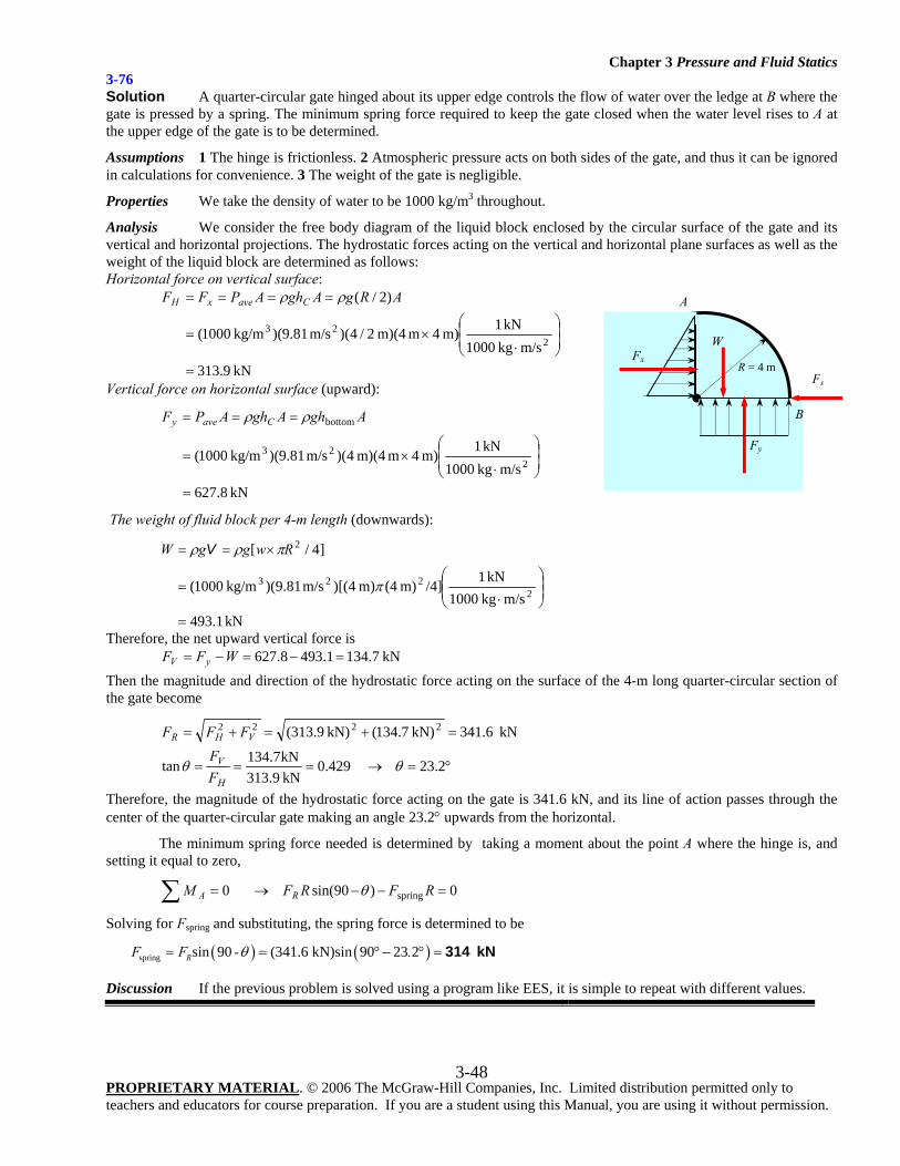
Chapter 3 Pressure and Fluid Statics
PROPRIETARY MATERIAL. © 2006 The McGraw-Hill Companies, Inc. Limited distribution permitted only to teachers and educators for course preparation. If you are a student using this Manual, you are using it without permission.
3-48
3-76 Solution A quarter-circular gate hinged about its upper edge controls the flow of water over the ledge at B where the gate is pressed by a spring. The minimum spring force required to keep the gate closed when the water level rises to A at the upper edge of the gate is to be determined.
Assumptions 1 The hinge is frictionless. 2 Atmospheric pressure acts on both sides of the gate, and thus it can be ignored in calculations for convenience. 3 The weight of the gate is negligible.
Properties We take the density of water to be 1000 kg/m3 throughout.
Analysis We consider the free body diagram of the liquid block enclosed by the circular surface of the gate and its vertical and horizontal projections. The hydrostatic forces acting on the vertical and horizontal plane surfaces as well as the weight of the liquid block are determined as follows: Horizontal force on vertical surface:
kN 9.313m/skg 1000
kN 1m) 4 m m)(4 2/4)(m/s 81.9)(kg/m 1000(
)2/(
223
=
⎟⎟⎠
⎞⎜⎜⎝
⎛
⋅×=
==== ARgAghAPFF CavexH ρρ
Vertical force on horizontal surface (upward):
kN 8.627m/skg 1000
kN 1m) 4 m m)(4 4)(m/s 81.9)(kg/m 1000(2
23
bottom
=
⎟⎟⎠
⎞⎜⎜⎝
⎛
⋅×=
=== AghAghAPF Cavey ρρ
The weight of fluid block per 4-m length (downwards):
kN1.493m/s kg1000
kN1/4]m) (4m) 4)[(m/s 81.9)( kg/m1000(
]4/[
2223
2
=
⎟⎟⎠
⎞⎜⎜⎝
⎛
⋅=
×==
π
πρρ RwggW V
Therefore, the net upward vertical force is kN 7.1341.4938.627 =−=−= WFF yV
Then the magnitude and direction of the hydrostatic force acting on the surface of the 4-m long quarter-circular section of the gate become
°=→===
=+=+=
23.2 429.0kN 9.313kN7.134tan
kN 6.341kN) 7.134(kN) 9.313( 2222
θθH
V
VHR
FF
FFF
Therefore, the magnitude of the hydrostatic force acting on the gate is 341.6 kN, and its line of action passes through the center of the quarter-circular gate making an angle 23.2° upwards from the horizontal.
The minimum spring force needed is determined by taking a moment about the point A where the hinge is, and setting it equal to zero,
0)90sin( 0 spring =−−→=∑ RFRFM RA θ
Solving for Fspring and substituting, the spring force is determined to be
( ) ( )spring sin 90 (341.6 kN)sin 90 23 2RF F - .θ= = ° − ° = 314 kN Discussion If the previous problem is solved using a program like EES, it is simple to repeat with different values.
R = 4 m
Fx
Fy
W
Fs
A
B
Chapter 3 Pressure and Fluid Statics
PROPRIETARY MATERIAL. © 2006 The McGraw-Hill Companies, Inc. Limited distribution permitted only to teachers and educators for course preparation. If you are a student using this Manual, you are using it without permission.
3-49
Buoyancy 3-77C Solution We are to define and discuss the buoyant force. Analysis The upward force a fluid exerts on an immersed body is called the buoyant force. The buoyant force is caused by the increase of pressure in a fluid with depth. The magnitude of the buoyant force acting on a submerged body whose volume is V is expressed as VgF fB ρ= . The direction of the buoyant force is upwards, and its line of
action passes through the centroid of the displaced volume. Discussion If the buoyant force is greater than the body’s weight, it floats.
3-78C Solution We are to compare the buoyant force on two spheres. Analysis The magnitude of the buoyant force acting on a submerged body whose volume is V is expressed as
VgF fB ρ= , which is independent of depth. Therefore, the buoyant forces acting on two identical spherical balls
submerged in water at different depths is the same. Discussion Buoyant force depends only on the volume of the object, not its density.
3-79C Solution We are to compare the buoyant force on two spheres. Analysis The magnitude of the buoyant force acting on a submerged body whose volume is V is expressed as
VgF fB ρ= , which is independent of the density of the body ( fρ is the fluid density). Therefore, the buoyant forces
acting on the 5-cm diameter aluminum and iron balls submerged in water is the same. Discussion Buoyant force depends only on the volume of the object, not its density.
3-80C Solution We are to compare the buoyant forces on a cube and a sphere. Analysis The magnitude of the buoyant force acting on a submerged body whose volume is V is expressed as
VgF fB ρ= , which is independent of the shape of the body. Therefore, the buoyant forces acting on the cube and
sphere made of copper submerged in water are the same since they have the same volume. Discussion The two objects have the same volume because they have the same mass and density.
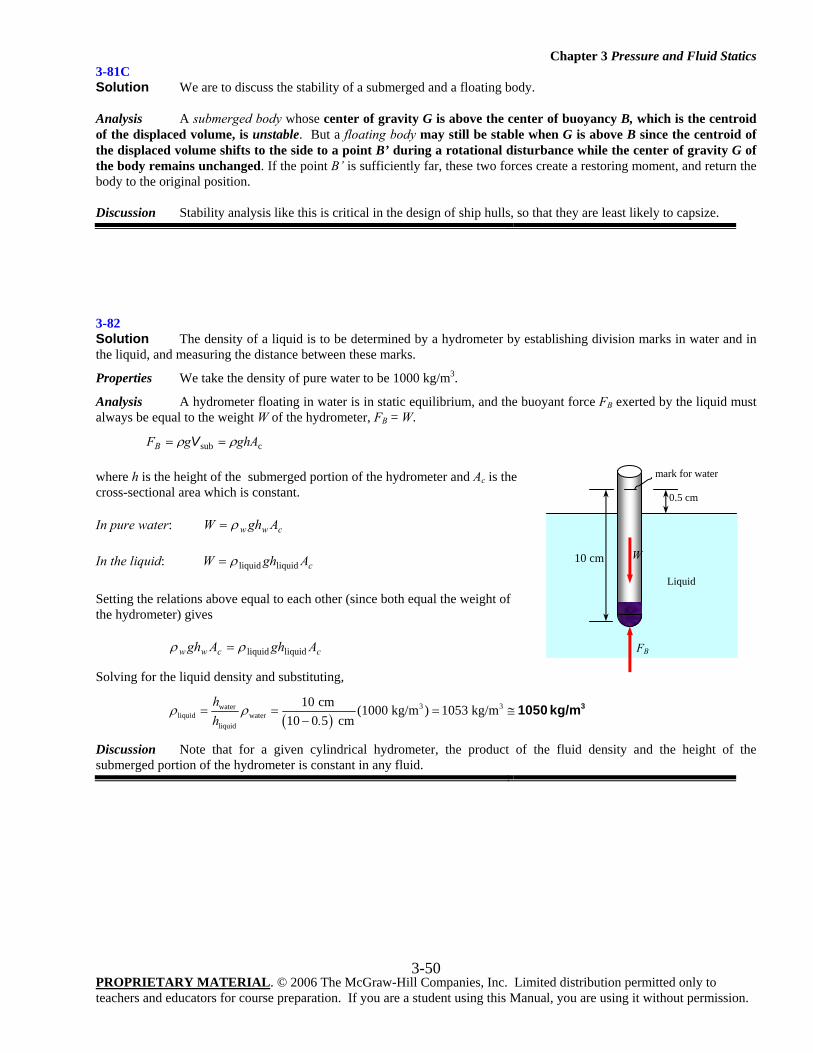
Chapter 3 Pressure and Fluid Statics
PROPRIETARY MATERIAL. © 2006 The McGraw-Hill Companies, Inc. Limited distribution permitted only to teachers and educators for course preparation. If you are a student using this Manual, you are using it without permission.
3-50
3-81C Solution We are to discuss the stability of a submerged and a floating body. Analysis A submerged body whose center of gravity G is above the center of buoyancy B, which is the centroid of the displaced volume, is unstable. But a floating body may still be stable when G is above B since the centroid of the displaced volume shifts to the side to a point B’ during a rotational disturbance while the center of gravity G of the body remains unchanged. If the point B’ is sufficiently far, these two forces create a restoring moment, and return the body to the original position. Discussion Stability analysis like this is critical in the design of ship hulls, so that they are least likely to capsize.
3-82 Solution The density of a liquid is to be determined by a hydrometer by establishing division marks in water and in the liquid, and measuring the distance between these marks.
Properties We take the density of pure water to be 1000 kg/m3.
Analysis A hydrometer floating in water is in static equilibrium, and the buoyant force FB exerted by the liquid must always be equal to the weight W of the hydrometer, FB = W.
csub ghAgFB ρρ == V
where h is the height of the submerged portion of the hydrometer and Ac is the cross-sectional area which is constant.
In pure water: cww AghW ρ=
In the liquid: cAghW liquidliquidρ=
Setting the relations above equal to each other (since both equal the weight of the hydrometer) gives
ccww AghAgh liquidliquidρρ =
Solving for the liquid density and substituting,
( )
3 3waterliquid water
liquid
10 cm (1000 kg/m ) 1053 kg/m10 0 5 cm
hh .
ρ ρ= = = ≅−
31050 kg/m
Discussion Note that for a given cylindrical hydrometer, the product of the fluid density and the height of the submerged portion of the hydrometer is constant in any fluid.
Liquid
0.5 cm
10 cm
mark for water
FB
W
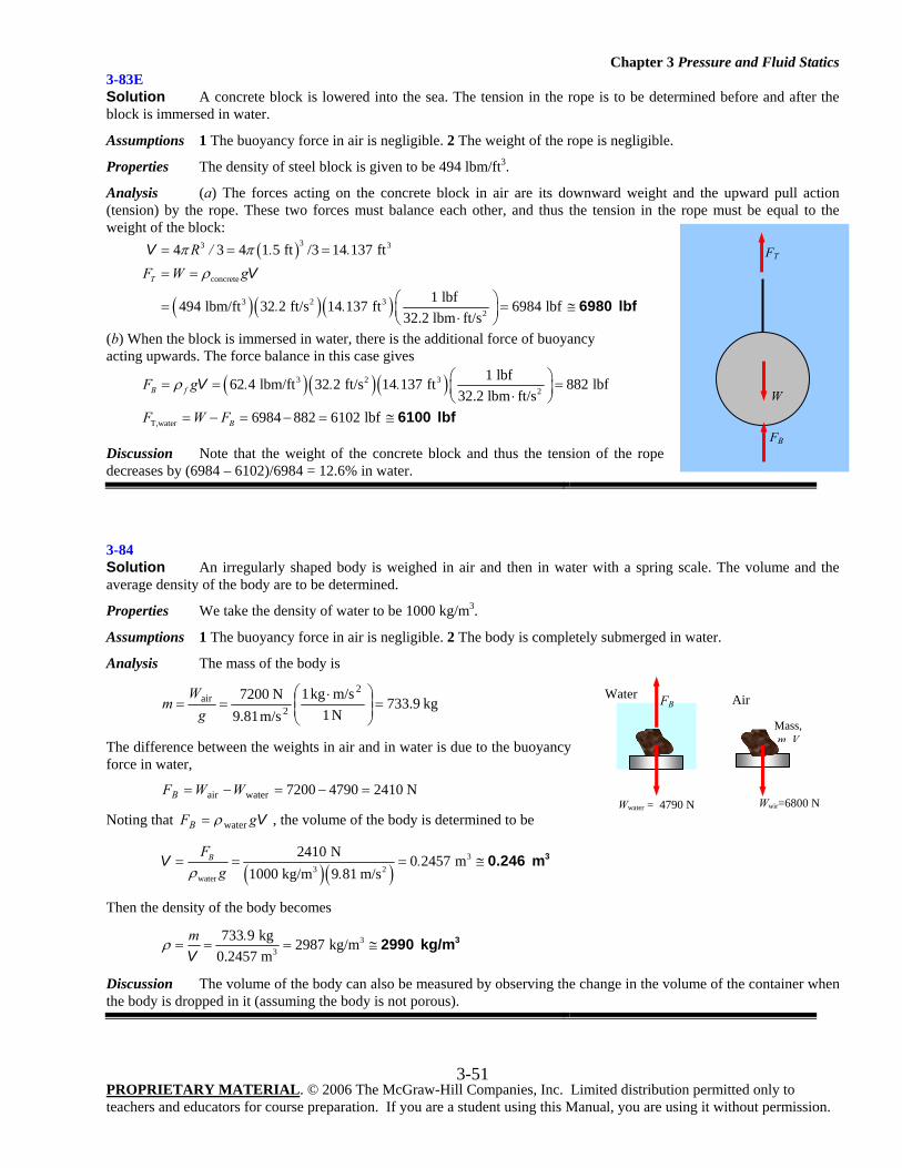
Chapter 3 Pressure and Fluid Statics
PROPRIETARY MATERIAL. © 2006 The McGraw-Hill Companies, Inc. Limited distribution permitted only to teachers and educators for course preparation. If you are a student using this Manual, you are using it without permission.
3-51
3-83E Solution A concrete block is lowered into the sea. The tension in the rope is to be determined before and after the block is immersed in water.
Assumptions 1 The buoyancy force in air is negligible. 2 The weight of the rope is negligible.
Properties The density of steel block is given to be 494 lbm/ft3.
Analysis (a) The forces acting on the concrete block in air are its downward weight and the upward pull action (tension) by the rope. These two forces must balance each other, and thus the tension in the rope must be equal to the weight of the block:
( )
( ) ( )( )
33 3
concrete
3 2 32
4 3 4 1 5 ft /3 14 137 ft
1 lbf494 lbm/ft 32 2 ft/s 14 137 ft 6984 lbf32.2 lbm ft/s
T
R / . .F W g
. .
π πρ
= = =
= =
⎛ ⎞= = ≅⎜ ⎟⋅⎝ ⎠
VV
6980 lbf
(b) When the block is immersed in water, there is the additional force of buoyancy acting upwards. The force balance in this case gives
( ) ( )( )3 2 3
2
T,water
1 lbf62 4 lbm/ft 32 2 ft/s 14 137 ft 882 lbf32.2 lbm ft/s
6984 882 6102 lbf
B f
B
F g . . .
F W F
ρ ⎛ ⎞= = =⎜ ⎟⋅⎝ ⎠= − = − = ≅
V
6100 lbf
Discussion Note that the weight of the concrete block and thus the tension of the rope decreases by (6984 – 6102)/6984 = 12.6% in water.
3-84 Solution An irregularly shaped body is weighed in air and then in water with a spring scale. The volume and the average density of the body are to be determined.
Properties We take the density of water to be 1000 kg/m3.
Assumptions 1 The buoyancy force in air is negligible. 2 The body is completely submerged in water.
Analysis The mass of the body is
kg9.733N 1m/s kg1
m/s 81.9N 7200 2
2air =⎟⎟
⎠
⎞⎜⎜⎝
⎛ ⋅==
gW
m
The difference between the weights in air and in water is due to the buoyancy force in water,
N 241047907200waterair =−=−= WWFB
Noting that VgFB waterρ= , the volume of the body is determined to be
( )( )3
3 2water
2410 N 0 2457 m1000 kg/m 9 81 m/s
BF.
g .ρ= = = ≅V 30.246 m
Then the density of the body becomes
33
733 9 kg 2987 kg/m0.2457 m
m .ρ = = = ≅V
32990 kg/m
Discussion The volume of the body can also be measured by observing the change in the volume of the container when the body is dropped in it (assuming the body is not porous).
Wwir=6800 N Wwater = 4790 N
FB Water Air
Mass, m V
W
FB
FT
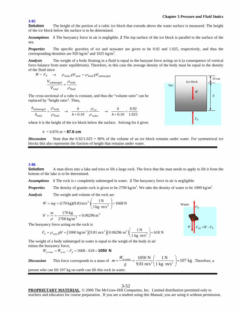
Chapter 3 Pressure and Fluid Statics
PROPRIETARY MATERIAL. © 2006 The McGraw-Hill Companies, Inc. Limited distribution permitted only to teachers and educators for course preparation. If you are a student using this Manual, you are using it without permission.
3-52
3-85 Solution The height of the portion of a cubic ice block that extends above the water surface is measured. The height of the ice block below the surface is to be determined.
Assumptions 1 The buoyancy force in air is negligible. 2 The top surface of the ice block is parallel to the surface of the sea.
Properties The specific gravities of ice and seawater are given to be 0.92 and 1.025, respectively, and thus the corresponding densities are 920 kg/m3 and 1025 kg/m3.
Analysis The weight of a body floating in a fluid is equal to the buoyant force acting on it (a consequence of vertical force balance from static equilibrium). Therefore, in this case the average density of the body must be equal to the density of the fluid since
W = FB → submergedfluidtotalbody VV gg ρρ =
fluid
body
total
submerged
ρ
ρ=
VV
The cross-sectional of a cube is constant, and thus the “volume ratio” can be replaced by “height ratio”. Then,
025.192.0
10.0
10.0
water
ice
fluid
body
total
submerged =+
→=+
→=h
hh
hh
hρρ
ρ
ρ
where h is the height of the ice block below the surface. Solving for h gives
h = 0.876 m = 87.6 cm
Discussion Note that the 0.92/1.025 = 90% of the volume of an ice block remains under water. For symmetrical ice blocks this also represents the fraction of height that remains under water.
3-86 Solution A man dives into a lake and tries to lift a large rock. The force that the man needs to apply to lift it from the bottom of the lake is to be determined.
Assumptions 1 The rock is c completely submerged in water. 2 The buoyancy force in air is negligible.
Properties The density of granite rock is given to be 2700 kg/m3. We take the density of water to be 1000 kg/m3.
Analysis The weight and volume of the rock are
3
3
22
m 0.06296 kg/m2700
kg170
N 1668m/s kg1N 1)m/s kg)(9.81170(
===
=⎟⎟⎠
⎞⎜⎜⎝
⎛
⋅==
ρm
mgW
V
The buoyancy force acting on the rock is
( )( )( )3 2 3water 2
1 N1000 kg/m 9 81 m/s 0 06296 m 618 N1 kg m/sBF g . .ρ
⎛ ⎞= = =⎜ ⎟⋅⎝ ⎠
V
The weight of a body submerged in water is equal to the weigh of the body in air minus the buoyancy force,
in water in air 1668 618BW W F= − = − = 1050 N
Discussion This force corresponds to a mass of in water2 2
1050 N 1 N 107 kg9 81 m/s 1 kg m/s
Wmg .
⎛ ⎞= = =⎜ ⎟⋅⎝ ⎠
. Therefore, a
person who can lift 107 kg on earth can lift this rock in water.
Sea
10 cm
h
FB
W
Ice block
W
FB Water
Fnet =W - FB
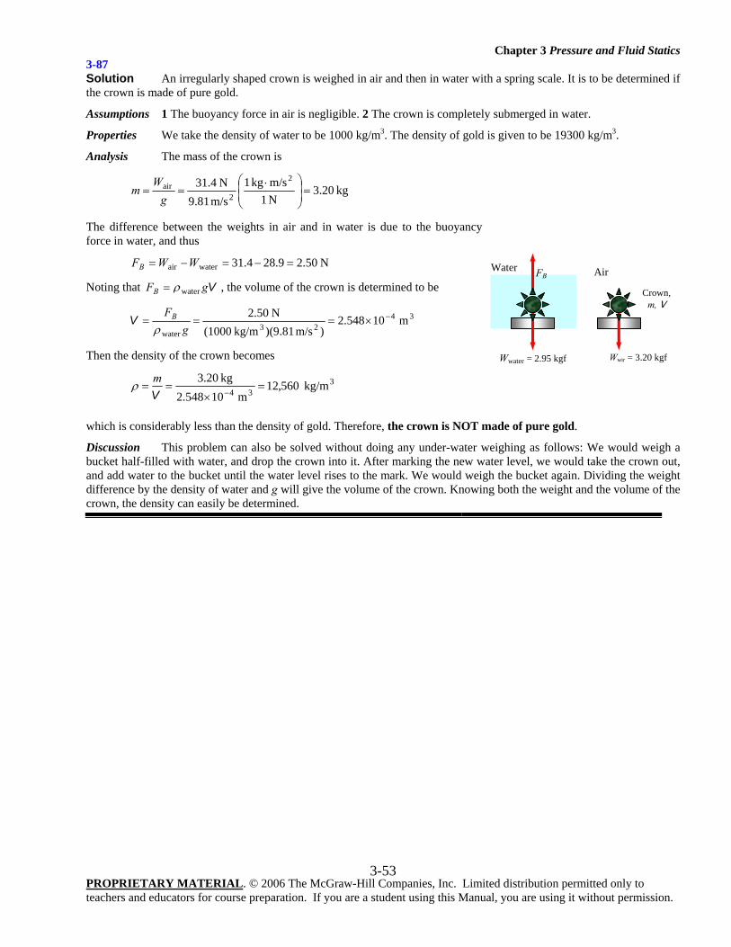
Chapter 3 Pressure and Fluid Statics
PROPRIETARY MATERIAL. © 2006 The McGraw-Hill Companies, Inc. Limited distribution permitted only to teachers and educators for course preparation. If you are a student using this Manual, you are using it without permission.
3-53
3-87 Solution An irregularly shaped crown is weighed in air and then in water with a spring scale. It is to be determined if the crown is made of pure gold.
Assumptions 1 The buoyancy force in air is negligible. 2 The crown is completely submerged in water.
Properties We take the density of water to be 1000 kg/m3. The density of gold is given to be 19300 kg/m3.
Analysis The mass of the crown is
kg20.3N 1m/skg 1
m/s 81.9N 4.31 2
2air =⎟
⎟⎠
⎞⎜⎜⎝
⎛ ⋅==
gW
m
The difference between the weights in air and in water is due to the buoyancy force in water, and thus
N 50.29.284.31waterair =−=−= WWFB
Noting that VgFB waterρ= , the volume of the crown is determined to be
3423
waterm 10548.2
)m/s 81.9)(kg/m (1000N 50.2 −×===
gFB
ρV
Then the density of the crown becomes
334
kg/m 560,12m 10548.2
kg 20.3 =
×==
−Vmρ
which is considerably less than the density of gold. Therefore, the crown is NOT made of pure gold.
Discussion This problem can also be solved without doing any under-water weighing as follows: We would weigh a bucket half-filled with water, and drop the crown into it. After marking the new water level, we would take the crown out, and add water to the bucket until the water level rises to the mark. We would weigh the bucket again. Dividing the weight difference by the density of water and g will give the volume of the crown. Knowing both the weight and the volume of the crown, the density can easily be determined.
Wwir = 3.20 kgf
Air
Crown, m, V
Wwater = 2.95 kgf
FB Water
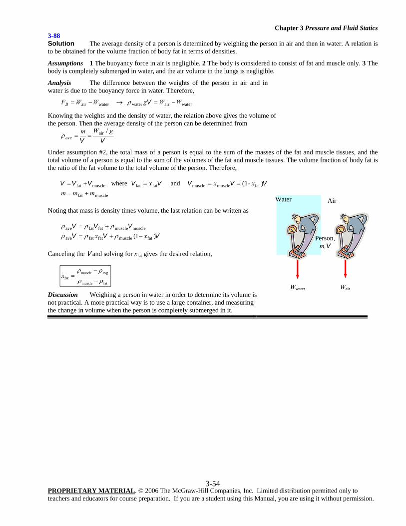
Chapter 3 Pressure and Fluid Statics
PROPRIETARY MATERIAL. © 2006 The McGraw-Hill Companies, Inc. Limited distribution permitted only to teachers and educators for course preparation. If you are a student using this Manual, you are using it without permission.
3-54
3-88 Solution The average density of a person is determined by weighing the person in air and then in water. A relation is to be obtained for the volume fraction of body fat in terms of densities.
Assumptions 1 The buoyancy force in air is negligible. 2 The body is considered to consist of fat and muscle only. 3 The body is completely submerged in water, and the air volume in the lungs is negligible.
Analysis The difference between the weights of the person in air and in water is due to the buoyancy force in water. Therefore,
waterairwaterwaterair WWgWWFB −=→−= Vρ
Knowing the weights and the density of water, the relation above gives the volume of the person. Then the average density of the person can be determined from
VVgWm /air
ave ==ρ
Under assumption #2, the total mass of a person is equal to the sum of the masses of the fat and muscle tissues, and the total volume of a person is equal to the sum of the volumes of the fat and muscle tissues. The volume fraction of body fat is the ratio of the fat volume to the total volume of the person. Therefore,
)-(1 and where
musclefat
fatmusclemusclefatfatmusclefat
mmmxxx
+====+= VVVVVVVV
Noting that mass is density times volume, the last relation can be written as
VVVVVV
)1( fatmusclefatfatave
musclemusclefatfatave
xx −+=+=
ρρρρρρ
Canceling the V and solving for xfat gives the desired relation,
muscle avgfat
muscle fat
xρ ρρ ρ
−=
−
Discussion Weighing a person in water in order to determine its volume is not practical. A more practical way is to use a large container, and measuring the change in volume when the person is completely submerged in it.
Wair
Air
Person, m,V
Wwater
Water
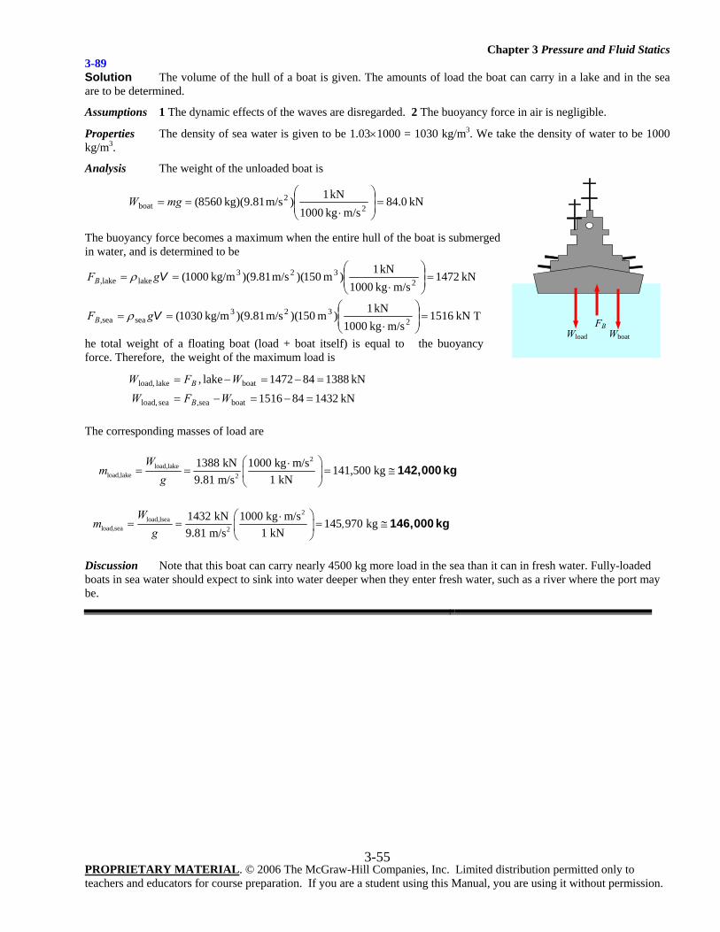
Chapter 3 Pressure and Fluid Statics
PROPRIETARY MATERIAL. © 2006 The McGraw-Hill Companies, Inc. Limited distribution permitted only to teachers and educators for course preparation. If you are a student using this Manual, you are using it without permission.
3-55
3-89 Solution The volume of the hull of a boat is given. The amounts of load the boat can carry in a lake and in the sea are to be determined.
Assumptions 1 The dynamic effects of the waves are disregarded. 2 The buoyancy force in air is negligible.
Properties The density of sea water is given to be 1.03×1000 = 1030 kg/m3. We take the density of water to be 1000 kg/m3.
Analysis The weight of the unloaded boat is
kN 84.0m/skg 1000
kN 1)m/s kg)(9.81 8560(2
2boat =⎟
⎟⎠
⎞⎜⎜⎝
⎛
⋅== mgW
The buoyancy force becomes a maximum when the entire hull of the boat is submerged in water, and is determined to be
kN1472m/s kg1000
kN1)m 150)(m/s 81.9)( kg/m1000( 2323
lakelake, =⎟⎟⎠
⎞⎜⎜⎝
⎛
⋅== VgFB ρ
kN1516m/s kg1000
kN1)m 150)(m/s 81.9)( kg/m1030( 2323
seasea, =⎟⎟⎠
⎞⎜⎜⎝
⎛
⋅== VgFB ρ T
he total weight of a floating boat (load + boat itself) is equal to the buoyancy force. Therefore, the weight of the maximum load is
kN 1432841516kN 1388841472lake,
boatsea,sea load,
boatlake load,
=−=−=
=−=−=
WFWWFW
B
B
The corresponding masses of load are
2
load,lakeload,lake 2
1388 kN 1000 kg m/s 141,500 kg1 kN9.81 m/s
Wm
g⎛ ⎞⋅
= = = ≅⎜ ⎟⎝ ⎠
142,000 kg
2
load,lseaload,sea 2
1432 kN 1000 kg m/s 145 970 kg1 kN9.81 m/s
Wm ,
g⎛ ⎞⋅
= = = ≅⎜ ⎟⎝ ⎠
146,000 kg
Discussion Note that this boat can carry nearly 4500 kg more load in the sea than it can in fresh water. Fully-loaded boats in sea water should expect to sink into water deeper when they enter fresh water, such as a river where the port may be.
Wload
FB Wboat
Chapter 3 Pressure and Fluid Statics
PROPRIETARY MATERIAL. © 2006 The McGraw-Hill Companies, Inc. Limited distribution permitted only to teachers and educators for course preparation. If you are a student using this Manual, you are using it without permission.
3-56
Fluids in Rigid-Body Motion 3-90C Solution We are to discuss when a fluid can be treated as a rigid body. Analysis A moving body of fluid can be treated as a rigid body when there are no shear stresses (i.e., no motion between fluid layers relative to each other) in the fluid body. Discussion When there is no relative motion between fluid particles, there are no viscous stresses, and pressure (normal stress) is the only stress.
3-91C Solution We are to compare the pressure at the bottom of a glass of water moving at various velocities. Analysis The water pressure at the bottom surface is the same for all cases since the acceleration for all four cases is zero. Discussion When any body, fluid or solid, moves at constant velocity, there is no acceleration, regardless of the direction of the movement.
3-92C Solution We are to compare the pressure in a glass of water for stationary and accelerating conditions. Analysis The pressure at the bottom surface is constant when the glass is stationary. For a glass moving on a horizontal plane with constant acceleration, water will collect at the back but the water depth will remain constant at the center. Therefore, the pressure at the midpoint will be the same for both glasses. But the bottom pressure will be low at the front relative to the stationary glass, and high at the back (again relative to the stationary glass). Note that the pressure in all cases is the hydrostatic pressure, which is directly proportional to the fluid height. Discussion We ignore any sloshing of the water.
3-93C Solution We are to analyze the pressure in a glass of water that is rotating. Analysis When a vertical cylindrical container partially filled with water is rotated about its axis and rigid body motion is established, the fluid level will drop at the center and rise towards the edges. Noting that hydrostatic pressure is proportional to fluid depth, the pressure at the mid point will drop and the pressure at the edges of the bottom surface will rise due to the rotation. Discussion The highest pressure occurs at the bottom corners of the container.

Chapter 3 Pressure and Fluid Statics
PROPRIETARY MATERIAL. © 2006 The McGraw-Hill Companies, Inc. Limited distribution permitted only to teachers and educators for course preparation. If you are a student using this Manual, you are using it without permission.
3-57
Tank A
8
Water
az = 5
Tank B
2 Water g
z
0
•2
• 1
•2
• 1
3-94 Solution A water tank is being towed by a truck on a level road, and the angle the free surface makes with the horizontal is measured. The acceleration of the truck is to be determined.
Assumptions 1 The road is horizontal so that acceleration has no vertical component (az = 0). 2 Effects of splashing, breaking, driving over bumps, and climbing hills are assumed to be secondary, and are not considered. 3 The acceleration remains constant.
Analysis We take the x-axis to be the direction of motion, the z-axis to be the upward vertical direction. The tangent of the angle the free surface makes with the horizontal is
z
x
aga+
=θtan
Solving for ax and substituting, 2m/s 2.63=°+=+= 15tan)0m/s 81.9(tan)( 2θzx aga Discussion Note that the analysis is valid for any fluid with constant density since we used no information that pertains to fluid properties in the solution.
3-95 Solution Two water tanks filled with water, one stationary and the other moving upwards at constant acceleration. The tank with the higher pressure at the bottom is to be determined.
Assumptions 1 The acceleration remains constant. 2 Water is an incompressible substance.
Properties We take the density of water to be 1000 kg/m3.
Analysis The pressure difference between two points 1 and 2 in an incompressible fluid is given by
))(()( 121212 zzagxxaPP zx −+−−−=− ρρ or ))(( 1221 zzagPP z −+=− ρ
since ax = 0. Taking point 2 at the free surface and point 1 at the tank bottom, we have atmPP =2 and hzz =− 12 and thus
hagPP z )(bottomgage ,1 +== ρ
Tank A: We have az = 0, and thus the pressure at the bottom is
22
23 bottom, kN/m5.78
m/s kg1000 kN1m) 8)(m/s 81.9)( kg/m1000( =⎟⎟
⎠
⎞⎜⎜⎝
⎛
⋅== AA ghP ρ
Tank B: We have az = +5 m/s2, and thus the pressure at the bottom is
22
23 bottom, kN/m6.29
m/s kg1000 kN1m) 2)(m/s 581.9)( kg/m1000()( =⎟⎟
⎠
⎞⎜⎜⎝
⎛
⋅+=+= BzB hagP ρ
Therefore, tank A has a higher pressure at the bottom. Discussion We can also solve this problem quickly by examining the relation hagP z )(bottom += ρ . Acceleration for tank B is about 1.5 times that of Tank A (14.81 vs 9.81 m/s2), but the fluid depth for tank A is 4 times that of tank B (8 m vs 2 m). Therefore, the tank with the larger acceleration-fluid height product (tank A in this case) will have a higher pressure at the bottom.
ax
θ = 15°
Water tank
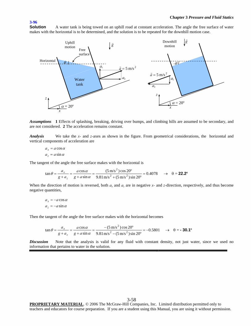
Chapter 3 Pressure and Fluid Statics
PROPRIETARY MATERIAL. © 2006 The McGraw-Hill Companies, Inc. Limited distribution permitted only to teachers and educators for course preparation. If you are a student using this Manual, you are using it without permission.
3-58
3-96 Solution A water tank is being towed on an uphill road at constant acceleration. The angle the free surface of water makes with the horizontal is to be determined, and the solution is to be repeated for the downhill motion case.
Assumptions 1 Effects of splashing, breaking, driving over bumps, and climbing hills are assumed to be secondary, and are not considered. 2 The acceleration remains constant.
Analysis We take the x- and z-axes as shown in the figure. From geometrical considerations, the horizontal and vertical components of acceleration are
αα
sincos
aaaa
z
x
==
The tangent of the angle the free surface makes with the horizontal is
4078.020sin)m/s 5(m/s 81.9
20cos)m/s 5(sin
costan 22
2=
°+°
=+
=+
=α
αθag
aag
a
z
x → θ = 22.2°
When the direction of motion is reversed, both ax and az are in negative x- and z-direction, respectively, and thus become negative quantities,
αα
sincos
aaaa
z
x
−=−=
Then the tangent of the angle the free surface makes with the horizontal becomes
5801.020sin)m/s 5(m/s 81.9
20cos)m/s 5(sin
costan 22
2−=
°−°−
=+
=+
=α
αθag
aag
a
z
x → θ = - 30.1°
Discussion Note that the analysis is valid for any fluid with constant density, not just water, since we used no information that pertains to water in the solution.
z
x
az
ax
2m/s 5=a
g
α = 20°
-θ
Downhill motion
z
x
ax
Free surface
az 2m/s 5=a
g
Water tank
α = 20°
θ Horizontal
Uphill motion
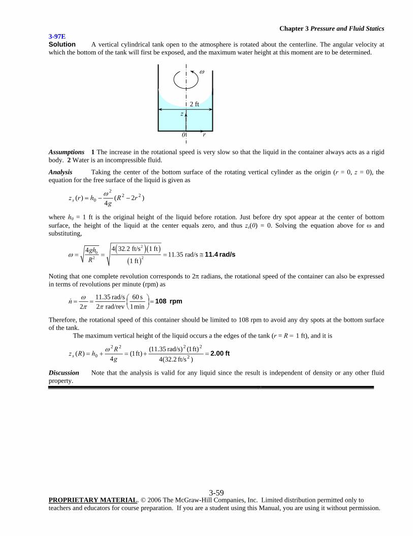
Chapter 3 Pressure and Fluid Statics
PROPRIETARY MATERIAL. © 2006 The McGraw-Hill Companies, Inc. Limited distribution permitted only to teachers and educators for course preparation. If you are a student using this Manual, you are using it without permission.
3-59
3-97E Solution A vertical cylindrical tank open to the atmosphere is rotated about the centerline. The angular velocity at which the bottom of the tank will first be exposed, and the maximum water height at this moment are to be determined.
Assumptions 1 The increase in the rotational speed is very slow so that the liquid in the container always acts as a rigid body. 2 Water is an incompressible fluid.
Analysis Taking the center of the bottom surface of the rotating vertical cylinder as the origin (r = 0, z = 0), the equation for the free surface of the liquid is given as
)2(4
)( 222
0 rRg
hrzs −−=ω
where h0 = 1 ft is the original height of the liquid before rotation. Just before dry spot appear at the center of bottom surface, the height of the liquid at the center equals zero, and thus zs(0) = 0. Solving the equation above for ω and substituting,
( )( )
( )
20
2 2
4 32 2 ft/s 1 ft411 35 rad/s
1 ft
.gh.
Rω = = = ≅ 11.4 rad/s
Noting that one complete revolution corresponds to 2π radians, the rotational speed of the container can also be expressed in terms of revolutions per minute (rpm) as
rpm 108=⎟⎠⎞
⎜⎝⎛==
min 1s 60
rad/rev2 rad/s35.11
2 ππωn
Therefore, the rotational speed of this container should be limited to 108 rpm to avoid any dry spots at the bottom surface of the tank.
The maximum vertical height of the liquid occurs a the edges of the tank (r = R = 1 ft), and it is
ft 2.00=+=+=)ft/s 2.32(4ft) 1( rad/s)35.11()ft 1(
4)( 2
2222
0 gRhRzs
ω
Discussion Note that the analysis is valid for any liquid since the result is independent of density or any other fluid property.
ω
2 ftz
r0
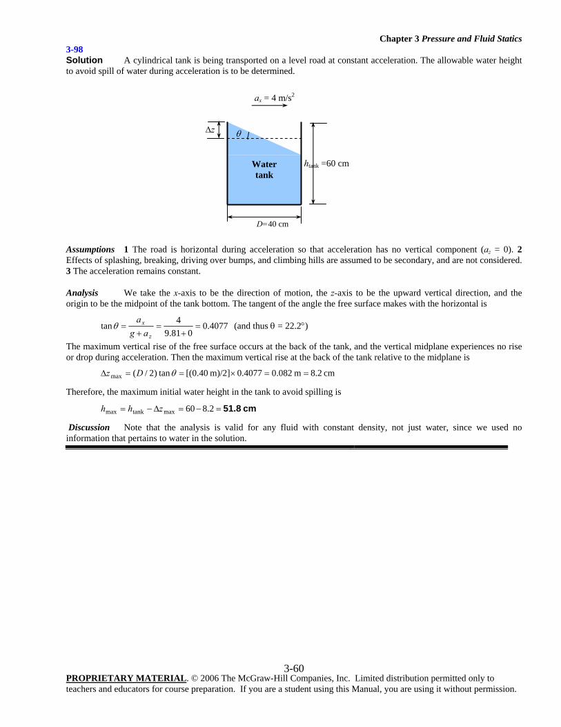
Chapter 3 Pressure and Fluid Statics
PROPRIETARY MATERIAL. © 2006 The McGraw-Hill Companies, Inc. Limited distribution permitted only to teachers and educators for course preparation. If you are a student using this Manual, you are using it without permission.
3-60
3-98 Solution A cylindrical tank is being transported on a level road at constant acceleration. The allowable water height to avoid spill of water during acceleration is to be determined.
Assumptions 1 The road is horizontal during acceleration so that acceleration has no vertical component (az = 0). 2 Effects of splashing, breaking, driving over bumps, and climbing hills are assumed to be secondary, and are not considered. 3 The acceleration remains constant.
Analysis We take the x-axis to be the direction of motion, the z-axis to be the upward vertical direction, and the origin to be the midpoint of the tank bottom. The tangent of the angle the free surface makes with the horizontal is
4077.0081.9
4tan =+
=+
=z
x
aga
θ (and thus θ = 22.2°)
The maximum vertical rise of the free surface occurs at the back of the tank, and the vertical midplane experiences no rise or drop during acceleration. Then the maximum vertical rise at the back of the tank relative to the midplane is
cm 8.2m 082.00.4077m)/2] 40.0[(tan)2/(max ==×==Δ θDz
Therefore, the maximum initial water height in the tank to avoid spilling is
cm 51.8=−=Δ−= 2.860maxtankmax zhh
Discussion Note that the analysis is valid for any fluid with constant density, not just water, since we used no information that pertains to water in the solution.
D=40 cm
ax = 4 m/s2
θ
htank =60 cm
Δz
Water tank
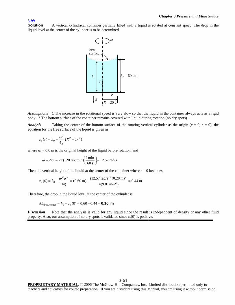
Chapter 3 Pressure and Fluid Statics
PROPRIETARY MATERIAL. © 2006 The McGraw-Hill Companies, Inc. Limited distribution permitted only to teachers and educators for course preparation. If you are a student using this Manual, you are using it without permission.
3-61
3-99 Solution A vertical cylindrical container partially filled with a liquid is rotated at constant speed. The drop in the liquid level at the center of the cylinder is to be determined.
Assumptions 1 The increase in the rotational speed is very slow so that the liquid in the container always acts as a rigid body. 2 The bottom surface of the container remains covered with liquid during rotation (no dry spots).
Analysis Taking the center of the bottom surface of the rotating vertical cylinder as the origin (r = 0, z = 0), the equation for the free surface of the liquid is given as
)2(4
)( 222
0 rRg
hrzs −−=ω
where h0 = 0.6 m is the original height of the liquid before rotation, and
rad/s57.12s 60
min 1 rev/min)120(22 =⎟⎠⎞
⎜⎝⎛== ππω n
Then the vertical height of the liquid at the center of the container where r = 0 becomes
m 44.0)m/s 81.9(4
m) 20.0( rad/s)57.12()m 06.0(4
)0( 2
2222
0 =−=−=gRhzs
ω
Therefore, the drop in the liquid level at the center of the cylinder is
m 0.16=−=−=Δ 44.060.0)0(0center drop, szhh
Discussion Note that the analysis is valid for any liquid since the result is independent of density or any other fluid property. Also, our assumption of no dry spots is validated since z0(0) is positive.
z
r
ω
zs
R = 20 cm
Free surface
ho = 60 cm
g
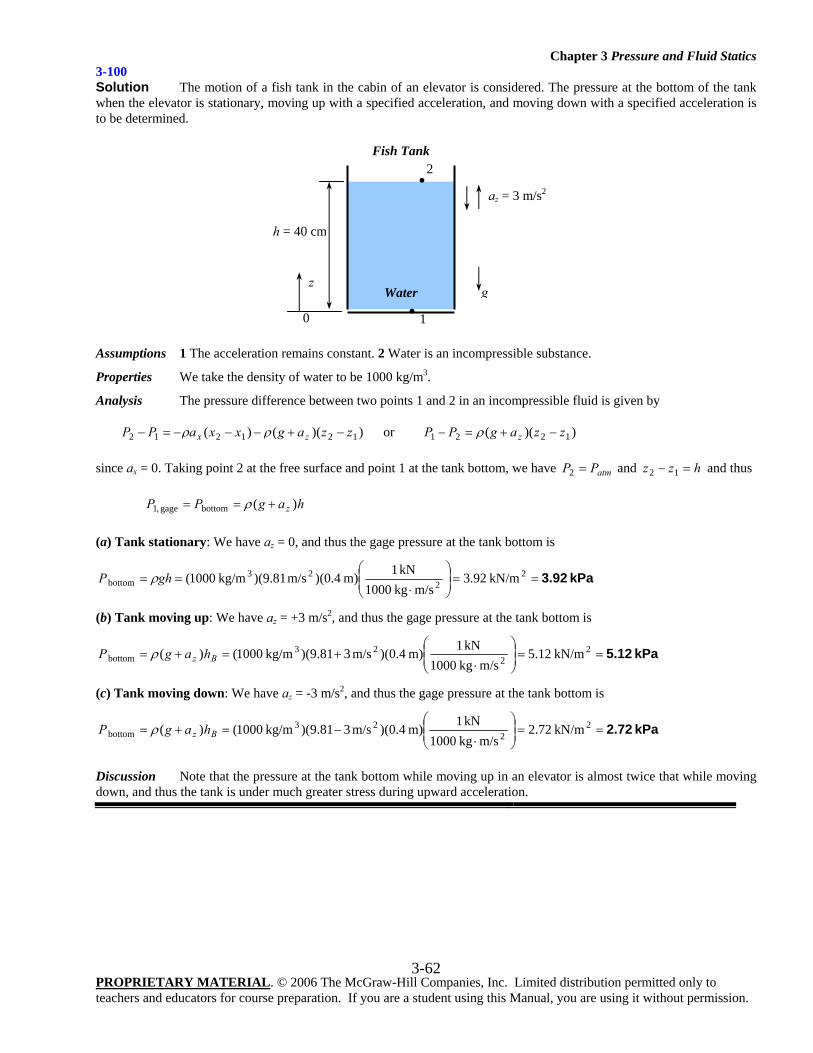
Chapter 3 Pressure and Fluid Statics
PROPRIETARY MATERIAL. © 2006 The McGraw-Hill Companies, Inc. Limited distribution permitted only to teachers and educators for course preparation. If you are a student using this Manual, you are using it without permission.
3-62
3-100 Solution The motion of a fish tank in the cabin of an elevator is considered. The pressure at the bottom of the tank when the elevator is stationary, moving up with a specified acceleration, and moving down with a specified acceleration is to be determined.
Assumptions 1 The acceleration remains constant. 2 Water is an incompressible substance.
Properties We take the density of water to be 1000 kg/m3.
Analysis The pressure difference between two points 1 and 2 in an incompressible fluid is given by
))(()( 121212 zzagxxaPP zx −+−−−=− ρρ or ))(( 1221 zzagPP z −+=− ρ
since ax = 0. Taking point 2 at the free surface and point 1 at the tank bottom, we have atmPP =2 and hzz =− 12 and thus
hagPP z )(bottomgage ,1 +== ρ
(a) Tank stationary: We have az = 0, and thus the gage pressure at the tank bottom is
kPa 3.92==⎟⎟⎠
⎞⎜⎜⎝
⎛
⋅== 2
223
bottom kN/m92.3m/s kg1000
kN1m) 4.0)(m/s 81.9)( kg/m1000(ghP ρ
(b) Tank moving up: We have az = +3 m/s2, and thus the gage pressure at the tank bottom is
kPa 5.12==⎟⎟⎠
⎞⎜⎜⎝
⎛
⋅+=+= 2
223
bottom kN/m12.5m/s kg1000
kN1m) 4.0)(m/s 381.9)( kg/m1000()( Bz hagP ρ
(c) Tank moving down: We have az = -3 m/s2, and thus the gage pressure at the tank bottom is
kPa 2.72==⎟⎟⎠
⎞⎜⎜⎝
⎛
⋅−=+= 2
223
bottom kN/m72.2m/s kg1000
kN1m) 4.0)(m/s 381.9)( kg/m1000()( Bz hagP ρ
Discussion Note that the pressure at the tank bottom while moving up in an elevator is almost twice that while moving down, and thus the tank is under much greater stress during upward acceleration.
Fish Tank
h = 40 cm
Water
az = 3 m/s2
gz
0
•2
• 1
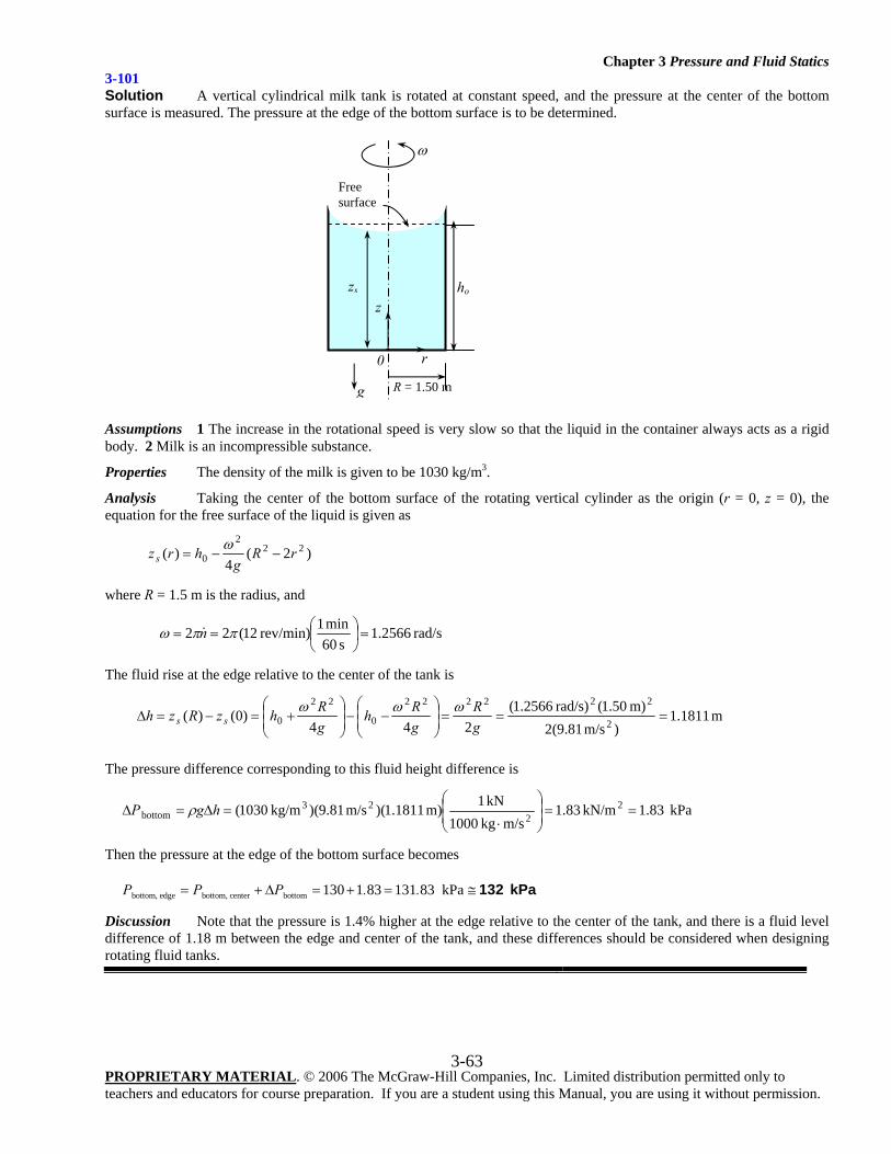
Chapter 3 Pressure and Fluid Statics
PROPRIETARY MATERIAL. © 2006 The McGraw-Hill Companies, Inc. Limited distribution permitted only to teachers and educators for course preparation. If you are a student using this Manual, you are using it without permission.
3-63
3-101 Solution A vertical cylindrical milk tank is rotated at constant speed, and the pressure at the center of the bottom surface is measured. The pressure at the edge of the bottom surface is to be determined.
Assumptions 1 The increase in the rotational speed is very slow so that the liquid in the container always acts as a rigid body. 2 Milk is an incompressible substance.
Properties The density of the milk is given to be 1030 kg/m3.
Analysis Taking the center of the bottom surface of the rotating vertical cylinder as the origin (r = 0, z = 0), the equation for the free surface of the liquid is given as
)2(4
)( 222
0 rRg
hrzs −−=ω
where R = 1.5 m is the radius, and
rad/s 2566.1s 60
min 1rev/min) 12(22 =⎟⎠⎞
⎜⎝⎛== ππω n
The fluid rise at the edge relative to the center of the tank is
m 1811.1)m/s 81.9(2
m) 50.1(rad/s) 2566.1(244
)0()(2
222222
0
22
0 ===⎟⎟⎠
⎞⎜⎜⎝
⎛−−⎟
⎟⎠
⎞⎜⎜⎝
⎛+=−=Δ
gR
gRh
gRhzRzh ss
ωωω
The pressure difference corresponding to this fluid height difference is
kPa 83.1kN/m 83.1m/skg 1000
kN 1m) 1811.1)(m/s 81.9)(kg/m 1030( 22
23bottom ==⎟
⎟⎠
⎞⎜⎜⎝
⎛
⋅=Δ=Δ hgP ρ
Then the pressure at the edge of the bottom surface becomes
bottom, edge bottom, center bottom 130 1 83 131 83 kPaP P P . .= + Δ = + = ≅ 132 kPa
Discussion Note that the pressure is 1.4% higher at the edge relative to the center of the tank, and there is a fluid level difference of 1.18 m between the edge and center of the tank, and these differences should be considered when designing rotating fluid tanks.
z
r
ω
zs
R = 1.50 m
Free surface
g
0
ho
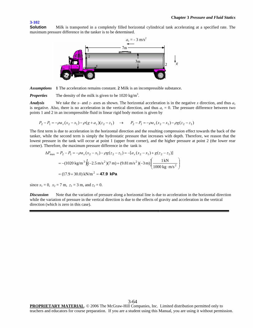
Chapter 3 Pressure and Fluid Statics
PROPRIETARY MATERIAL. © 2006 The McGraw-Hill Companies, Inc. Limited distribution permitted only to teachers and educators for course preparation. If you are a student using this Manual, you are using it without permission.
3-64
3-102 Solution Milk is transported in a completely filled horizontal cylindrical tank accelerating at a specified rate. The maximum pressure difference in the tanker is to be determined.
Assumptions 1 The acceleration remains constant. 2 Milk is an incompressible substance.
Properties The density of the milk is given to be 1020 kg/m3.
Analysis We take the x- and z- axes as shown. The horizontal acceleration is in the negative x direction, and thus ax is negative. Also, there is no acceleration in the vertical direction, and thus az = 0. The pressure difference between two points 1 and 2 in an incompressible fluid in linear rigid body motion is given by
))(()( 121212 zzagxxaPP zx −+−−−=− ρρ → )()( 121212 zzgxxaPP x −−−−=− ρρ
The first term is due to acceleration in the horizontal direction and the resulting compression effect towards the back of the tanker, while the second term is simply the hydrostatic pressure that increases with depth. Therefore, we reason that the lowest pressure in the tank will occur at point 1 (upper front corner), and the higher pressure at point 2 (the lower rear corner). Therefore, the maximum pressure difference in the tank is
[ ]kPa 47.9=+=
⎟⎟⎠
⎞⎜⎜⎝
⎛
⋅−+−−=
−+−−=−−−−=−=Δ
2
2223
1212121212max
kN/m)0.309.17(
m/s kg1000 kN1m) 3)(m/s 81.9(m) 7)(m/s 5.2() kg/m1020(
)]()([)()( zzgxxazzgxxaPPP xx ρρ
since x1 = 0, x2 = 7 m, z1 = 3 m, and z2 = 0.
Discussion Note that the variation of pressure along a horizontal line is due to acceleration in the horizontal direction while the variation of pressure in the vertical direction is due to the effects of gravity and acceleration in the vertical direction (which is zero in this case).
z
x0 •
2
• 1
g
ax = - 3 m/s2
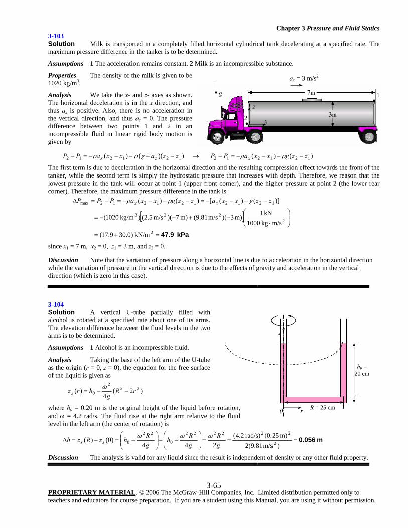
Chapter 3 Pressure and Fluid Statics
PROPRIETARY MATERIAL. © 2006 The McGraw-Hill Companies, Inc. Limited distribution permitted only to teachers and educators for course preparation. If you are a student using this Manual, you are using it without permission.
3-65
3-103 Solution Milk is transported in a completely filled horizontal cylindrical tank decelerating at a specified rate. The maximum pressure difference in the tanker is to be determined.
Assumptions 1 The acceleration remains constant. 2 Milk is an incompressible substance.
Properties The density of the milk is given to be 1020 kg/m3.
Analysis We take the x- and z- axes as shown. The horizontal deceleration is in the x direction, and thus ax is positive. Also, there is no acceleration in the vertical direction, and thus az = 0. The pressure difference between two points 1 and 2 in an incompressible fluid in linear rigid body motion is given by
))(()( 121212 zzagxxaPP zx −+−−−=− ρρ → )()( 121212 zzgxxaPP x −−−−=− ρρ
The first term is due to deceleration in the horizontal direction and the resulting compression effect towards the front of the tanker, while the second term is simply the hydrostatic pressure that increases with depth. Therefore, we reason that the lowest pressure in the tank will occur at point 1 (upper front corner), and the higher pressure at point 2 (the lower rear corner). Therefore, the maximum pressure difference in the tank is
[ ]kPa 47.9=+=
⎟⎟⎠
⎞⎜⎜⎝
⎛
⋅−+−−=
−+−−=−−−−=−=Δ
2
2223
1212121212max
kN/m)0.309.17(
m/s kg1000 kN1m) 3)(m/s 81.9(m) 7)(m/s 5.2() kg/m1020(
)]()([)()( zzgxxazzgxxaPPP xx ρρ
since x1 = 7 m, x2 = 0, z1 = 3 m, and z2 = 0.
Discussion Note that the variation of pressure along a horizontal line is due to acceleration in the horizontal direction while the variation of pressure in the vertical direction is due to the effects of gravity and acceleration in the vertical direction (which is zero in this case).
3-104 Solution A vertical U-tube partially filled with alcohol is rotated at a specified rate about one of its arms. The elevation difference between the fluid levels in the two arms is to be determined.
Assumptions 1 Alcohol is an incompressible fluid.
Analysis Taking the base of the left arm of the U-tube as the origin (r = 0, z = 0), the equation for the free surface of the liquid is given as
)2(4
)( 222
0 rRg
hrzs −−=ω
where h0 = 0.20 m is the original height of the liquid before rotation, and ω = 4.2 rad/s. The fluid rise at the right arm relative to the fluid level in the left arm (the center of rotation) is
m 0.056===⎟⎟⎠
⎞⎜⎜⎝
⎛−−⎟⎟
⎠
⎞⎜⎜⎝
⎛+=−=Δ
)m/s 81.9(2m) 25.0( rad/s)2.4(
244)0()( 2
222222
0
22
0 gR
gRh
gRhzRzh ss
ωωω
Discussion The analysis is valid for any liquid since the result is independent of density or any other fluid property.
z
x•2
•1g
ax = 3 m/s2
R = 25 cm
h0 = 20 cm
z
r 0
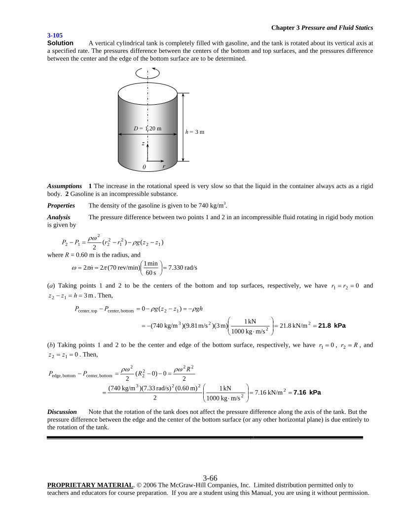
Chapter 3 Pressure and Fluid Statics
PROPRIETARY MATERIAL. © 2006 The McGraw-Hill Companies, Inc. Limited distribution permitted only to teachers and educators for course preparation. If you are a student using this Manual, you are using it without permission.
3-66
3-105 Solution A vertical cylindrical tank is completely filled with gasoline, and the tank is rotated about its vertical axis at a specified rate. The pressures difference between the centers of the bottom and top surfaces, and the pressures difference between the center and the edge of the bottom surface are to be determined.
Assumptions 1 The increase in the rotational speed is very slow so that the liquid in the container always acts as a rigid body. 2 Gasoline is an incompressible substance.
Properties The density of the gasoline is given to be 740 kg/m3.
Analysis The pressure difference between two points 1 and 2 in an incompressible fluid rotating in rigid body motion is given by
)()(2 12
21
22
2
12 zzgrrPP −−−=− ρρω
where R = 0.60 m is the radius, and
rad/s330.7s 60
min 1 rev/min)70(22 =⎟⎠⎞
⎜⎝⎛== ππω n
(a) Taking points 1 and 2 to be the centers of the bottom and top surfaces, respectively, we have 021 == rr and m 312 ==− hzz . Then,
kPa 21.8==⎟⎟⎠
⎞⎜⎜⎝
⎛
⋅−=
−=−−=−
22
23
12 bottomcenter, topcenter,
kN/m8.21m/s kg1000
kN1m) 3)(m/s 81.9)( kg/m740(
)(0 ghzzgPP ρρ
(b) Taking points 1 and 2 to be the center and edge of the bottom surface, respectively, we have 01 =r , Rr =2 , and 012 == zz . Then,
20)0(
2
2222
2
bottomcenter, bottomedge,RRPP ρωρω
=−−=−
kPa 7.16==⎟⎟⎠
⎞⎜⎜⎝
⎛
⋅= 2
2
223 kN/m16.7
m/s kg1000 kN1
2m) 60.0( rad/s)33.7)( kg/m740(
Discussion Note that the rotation of the tank does not affect the pressure difference along the axis of the tank. But the pressure difference between the edge and the center of the bottom surface (or any other horizontal plane) is due entirely to the rotation of the tank.
h = 3 m D = 1.20 m
z
r0
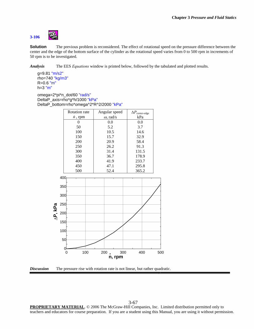
Chapter 3 Pressure and Fluid Statics
PROPRIETARY MATERIAL. © 2006 The McGraw-Hill Companies, Inc. Limited distribution permitted only to teachers and educators for course preparation. If you are a student using this Manual, you are using it without permission.
3-67
3-106
Solution The previous problem is reconsidered. The effect of rotational speed on the pressure difference between the center and the edge of the bottom surface of the cylinder as the rotational speed varies from 0 to 500 rpm in increments of 50 rpm is to be investigated. Analysis The EES Equations window is printed below, followed by the tabulated and plotted results.
g=9.81 "m/s2" rho=740 "kg/m3" R=0.6 "m" h=3 "m"
omega=2*pi*n_dot/60 "rad/s" DeltaP_axis=rho*g*h/1000 "kPa" DeltaP_bottom=rho*omega^2*R^2/2000 "kPa"
Rotation rate n , rpm
Angular speed ω, rad/s
ΔPcenter-edge kPa
0 50
100 150 200 250 300 350 400 450 500
0.0 5.2
10.5 15.7 20.9 26.2 31.4 36.7 41.9 47.1 52.4
0.0 3.7
14.6 32.9 58.4 91.3
131.5 178.9 233.7 295.8 365.2
Discussion The pressure rise with rotation rate is not linear, but rather quadratic.
0 100 200 300 400 5000
50
100
150
200
250
300
350
400
n, rpm
ΔP, k
Pa
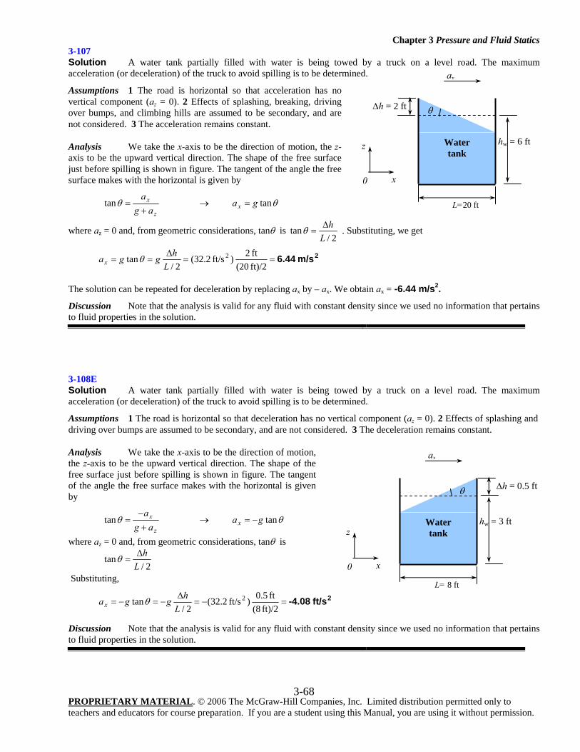
Chapter 3 Pressure and Fluid Statics
PROPRIETARY MATERIAL. © 2006 The McGraw-Hill Companies, Inc. Limited distribution permitted only to teachers and educators for course preparation. If you are a student using this Manual, you are using it without permission.
3-68
3-107 Solution A water tank partially filled with water is being towed by a truck on a level road. The maximum acceleration (or deceleration) of the truck to avoid spilling is to be determined.
Assumptions 1 The road is horizontal so that acceleration has no vertical component (az = 0). 2 Effects of splashing, breaking, driving over bumps, and climbing hills are assumed to be secondary, and are not considered. 3 The acceleration remains constant.
Analysis We take the x-axis to be the direction of motion, the z-axis to be the upward vertical direction. The shape of the free surface just before spilling is shown in figure. The tangent of the angle the free surface makes with the horizontal is given by
z
x
aga+
=θtan → θtangax =
where az = 0 and, from geometric considerations, tanθ is 2/
tanL
hΔ=θ . Substituting, we get
2m/s 6.44==Δ
==ft)/2 (20ft 2)ft/s 2.32(
2/tan 2
Lhggax θ
The solution can be repeated for deceleration by replacing ax by – ax. We obtain ax = -6.44 m/s2.
Discussion Note that the analysis is valid for any fluid with constant density since we used no information that pertains to fluid properties in the solution.
3-108E Solution A water tank partially filled with water is being towed by a truck on a level road. The maximum acceleration (or deceleration) of the truck to avoid spilling is to be determined.
Assumptions 1 The road is horizontal so that deceleration has no vertical component (az = 0). 2 Effects of splashing and driving over bumps are assumed to be secondary, and are not considered. 3 The deceleration remains constant.
Analysis We take the x-axis to be the direction of motion, the z-axis to be the upward vertical direction. The shape of the free surface just before spilling is shown in figure. The tangent of the angle the free surface makes with the horizontal is given by
z
x
aga
+−
=θtan → θtangax −=
where az = 0 and, from geometric considerations, tanθ is
2/tan
LhΔ
=θ
Substituting,
2ft/s -4.08=−=Δ
−=−=ft)/2 (8
ft 5.0)ft/s 2.32(2/
tan 2
Lhggax θ
Discussion Note that the analysis is valid for any fluid with constant density since we used no information that pertains to fluid properties in the solution.
L=20 ft
ax
θ
hw = 6 ft
Δh = 2 ft
Water tank
z
x0
L= 8 ft
ax
θ
hw = 3 ft
Δh = 0.5 ft
Water tank z
x0
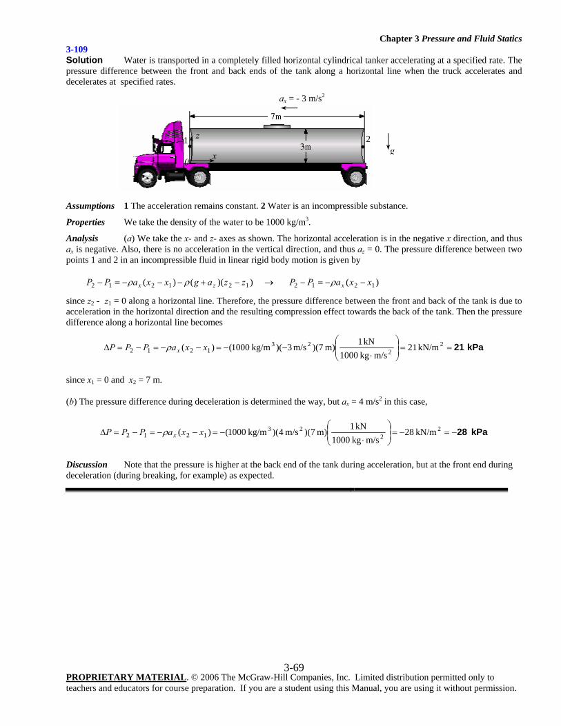
Chapter 3 Pressure and Fluid Statics
PROPRIETARY MATERIAL. © 2006 The McGraw-Hill Companies, Inc. Limited distribution permitted only to teachers and educators for course preparation. If you are a student using this Manual, you are using it without permission.
3-69
3-109 Solution Water is transported in a completely filled horizontal cylindrical tanker accelerating at a specified rate. The pressure difference between the front and back ends of the tank along a horizontal line when the truck accelerates and decelerates at specified rates.
Assumptions 1 The acceleration remains constant. 2 Water is an incompressible substance.
Properties We take the density of the water to be 1000 kg/m3.
Analysis (a) We take the x- and z- axes as shown. The horizontal acceleration is in the negative x direction, and thus ax is negative. Also, there is no acceleration in the vertical direction, and thus az = 0. The pressure difference between two points 1 and 2 in an incompressible fluid in linear rigid body motion is given by
))(()( 121212 zzagxxaPP zx −+−−−=− ρρ → )( 1212 xxaPP x −−=− ρ
since z2 - z1 = 0 along a horizontal line. Therefore, the pressure difference between the front and back of the tank is due to acceleration in the horizontal direction and the resulting compression effect towards the back of the tank. Then the pressure difference along a horizontal line becomes
kPa 21==⎟⎟⎠
⎞⎜⎜⎝
⎛
⋅−−=−−=−=Δ 2
223
1212 kN/m21m/s kg1000
kN1m) 7)(m/s 3)( kg/m1000( )( xxaPPP xρ
since x1 = 0 and x2 = 7 m.
(b) The pressure difference during deceleration is determined the way, but ax = 4 m/s2 in this case,
kPa 28−=−=⎟⎟⎠
⎞⎜⎜⎝
⎛
⋅−=−−=−=Δ 2
223
1212 kN/m28m/s kg1000
kN1m) 7)(m/s 4)( kg/m1000( )( xxaPPP xρ
Discussion Note that the pressure is higher at the back end of the tank during acceleration, but at the front end during deceleration (during breaking, for example) as expected.
z
x0
•2
• 1 g
ax = - 3 m/s2
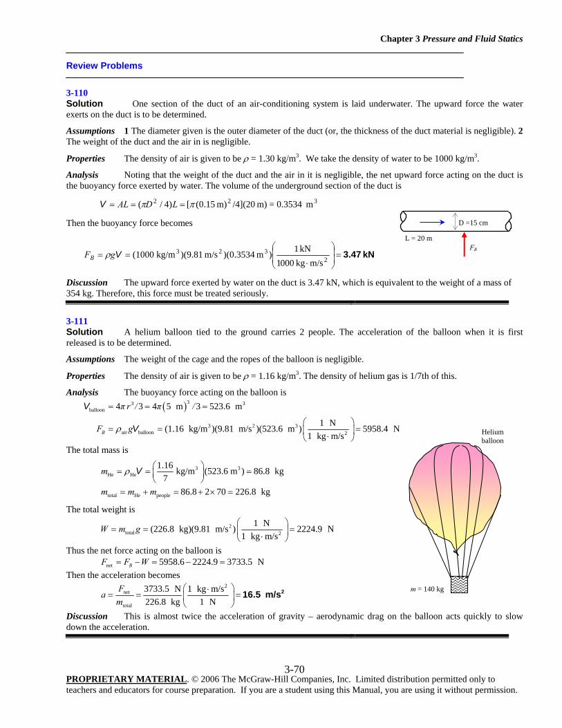
Chapter 3 Pressure and Fluid Statics
PROPRIETARY MATERIAL. © 2006 The McGraw-Hill Companies, Inc. Limited distribution permitted only to teachers and educators for course preparation. If you are a student using this Manual, you are using it without permission.
3-70
Review Problems
3-110 Solution One section of the duct of an air-conditioning system is laid underwater. The upward force the water exerts on the duct is to be determined.
Assumptions 1 The diameter given is the outer diameter of the duct (or, the thickness of the duct material is negligible). 2 The weight of the duct and the air in is negligible.
Properties The density of air is given to be ρ = 1.30 kg/m3. We take the density of water to be 1000 kg/m3.
Analysis Noting that the weight of the duct and the air in it is negligible, the net upward force acting on the duct is the buoyancy force exerted by water. The volume of the underground section of the duct is
m 0.3534=m) /4](20m) 15.0([)4/( 322 ππ === LDALV
Then the buoyancy force becomes
kN 3.47=⎟⎟⎠
⎞⎜⎜⎝
⎛
⋅==
2323
m/skg 0001kN 1)m )(0.3534m/s )(9.81kg/m (1000VgFB ρ
Discussion The upward force exerted by water on the duct is 3.47 kN, which is equivalent to the weight of a mass of 354 kg. Therefore, this force must be treated seriously.
3-111 Solution A helium balloon tied to the ground carries 2 people. The acceleration of the balloon when it is first released is to be determined.
Assumptions The weight of the cage and the ropes of the balloon is negligible.
Properties The density of air is given to be ρ = 1.16 kg/m3. The density of helium gas is 1/7th of this.
Analysis The buoyancy force acting on the balloon is
( )33 3
balloon
3 2 3air balloon 2
4 3 4 5 m 3 523.6 m
1 N(1.16 kg/m )(9.81 m/s )(523.6 m ) 5958.4 N1 kg m/sB
π r / π /
F gρ
= = =
⎛ ⎞= = =⎜ ⎟⋅⎝ ⎠
V
V
The total mass is
3 3
He He
total He people
1.16 kg/m (523.6 m ) 86.8 kg7
86.8 2 70 226.8 kg
m
m m m
ρ ⎛ ⎞= = =⎜ ⎟⎝ ⎠
= + = + × =
V
The total weight is
2total 2
1 N(226.8 kg)(9.81 m/s ) 2224.9 N1 kg m/s
W m g⎛ ⎞
= = =⎜ ⎟⋅⎝ ⎠
Thus the net force acting on the balloon is net 5958.6 2224.9 3733.5 NBF F W= − = − = Then the acceleration becomes
2
net
total
3733.5 N 1 kg m/s226.8 kg 1 N
Fa
m⎛ ⎞⋅
= = =⎜ ⎟⎝ ⎠
216.5 m/s
Discussion This is almost twice the acceleration of gravity – aerodynamic drag on the balloon acts quickly to slow down the acceleration.
Helium balloon
m = 140 kg
D =15 cm
L = 20 m FB
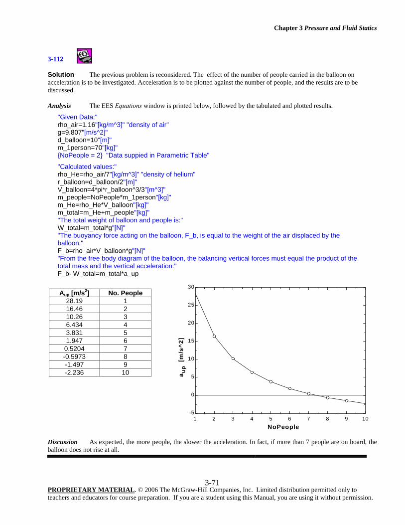
Chapter 3 Pressure and Fluid Statics
PROPRIETARY MATERIAL. © 2006 The McGraw-Hill Companies, Inc. Limited distribution permitted only to teachers and educators for course preparation. If you are a student using this Manual, you are using it without permission.
3-71
3-112
Solution The previous problem is reconsidered. The effect of the number of people carried in the balloon on acceleration is to be investigated. Acceleration is to be plotted against the number of people, and the results are to be discussed. Analysis The EES Equations window is printed below, followed by the tabulated and plotted results.
"Given Data:" rho_air=1.16"[kg/m^3]" "density of air" g=9.807"[m/s^2]" d_balloon=10"[m]" m_1person=70"[kg]" {NoPeople = 2} "Data suppied in Parametric Table"
"Calculated values:" rho_He=rho_air/7"[kg/m^3]" "density of helium" r_balloon=d_balloon/2"[m]" V_balloon=4*pi*r_balloon^3/3"[m^3]" m_people=NoPeople*m_1person"[kg]" m_He=rho_He*V_balloon"[kg]" m_total=m_He+m_people"[kg]" "The total weight of balloon and people is:" W_total=m_total*g"[N]" "The buoyancy force acting on the balloon, F_b, is equal to the weight of the air displaced by the balloon." F_b=rho_air*V_balloon*g"[N]" "From the free body diagram of the balloon, the balancing vertical forces must equal the product of the total mass and the vertical acceleration:" F_b- W_total=m_total*a_up
Discussion As expected, the more people, the slower the acceleration. In fact, if more than 7 people are on board, the balloon does not rise at all.
1 2 3 4 5 6 7 8 9 10-5
0
5
10
15
20
25
30
NoPeople
a up
[m/s
^2]
Aup [m/s2] No. People 28.19 1 16.46 2 10.26 3 6.434 4 3.831 5 1.947 6
0.5204 7 -0.5973 8 -1.497 9 -2.236 10
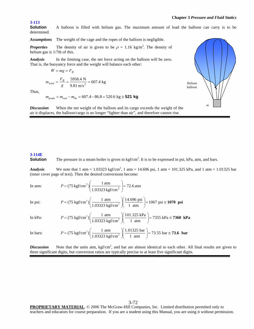
Chapter 3 Pressure and Fluid Statics
PROPRIETARY MATERIAL. © 2006 The McGraw-Hill Companies, Inc. Limited distribution permitted only to teachers and educators for course preparation. If you are a student using this Manual, you are using it without permission.
3-72
3-113 Solution A balloon is filled with helium gas. The maximum amount of load the balloon can carry is to be determined.
Assumptions The weight of the cage and the ropes of the balloon is negligible.
Properties The density of air is given to be ρ = 1.16 kg/m3. The density of helium gas is 1/7th of this.
Analysis In the limiting case, the net force acting on the balloon will be zero. That is, the buoyancy force and the weight will balance each other:
kg 607.4
m/s 9.81N 5958.42
===
==
gF
m
FmgW
Btotal
B
Thus, people total He 607.4 86.8 520 6 kgm m m .= − = − = ≅ 521 kg Discussion When the net weight of the balloon and its cargo exceeds the weight of the air it displaces, the balloon/cargo is no longer “lighter than air”, and therefore cannot rise.
3-114E Solution The pressure in a steam boiler is given in kgf/cm2. It is to be expressed in psi, kPa, atm, and bars.
Analysis We note that 1 atm = 1.03323 kgf/cm2, 1 atm = 14.696 psi, 1 atm = 101.325 kPa, and 1 atm = 1.01325 bar (inner cover page of text). Then the desired conversions become:
In atm: atm 6.72kgf/cm 1.03323
atm 1)kgf/cm (75
22 =⎟
⎟⎠
⎞⎜⎜⎝
⎛=P
In psi: 22
1 atm 14 696 psi(75 kgf/cm ) 1067 psi1 atm1.03323 kgf/cm.P
⎛ ⎞⎛ ⎞= = ≅⎜ ⎟⎜ ⎟
⎝ ⎠⎝ ⎠1070 psi
In kPa: 22
1 atm 101 325 kPa(75 kgf/cm ) 7355 kPa1 atm1.03323 kgf/cm.P
⎛ ⎞⎛ ⎞= = ≅⎜ ⎟⎜ ⎟
⎝ ⎠⎝ ⎠7360 kPa
In bars: 22
1 atm 1 01325 bar(75 kgf/cm ) 73 55 bar1 atm1.03323 kgf/cm
.P .⎛ ⎞⎛ ⎞
= = ≅⎜ ⎟⎜ ⎟⎝ ⎠⎝ ⎠
73.6 bar
Discussion Note that the units atm, kgf/cm2, and bar are almost identical to each other. All final results are given to three significant digits, but conversion ratios are typically precise to at least five significant digits.
Helium balloon
m
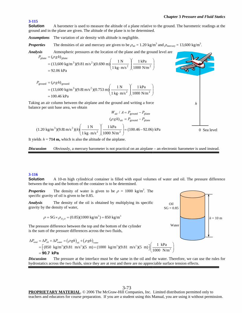
Chapter 3 Pressure and Fluid Statics
PROPRIETARY MATERIAL. © 2006 The McGraw-Hill Companies, Inc. Limited distribution permitted only to teachers and educators for course preparation. If you are a student using this Manual, you are using it without permission.
3-73
3-115 Solution A barometer is used to measure the altitude of a plane relative to the ground. The barometric readings at the ground and in the plane are given. The altitude of the plane is to be determined.
Assumptions The variation of air density with altitude is negligible.
Properties The densities of air and mercury are given to be ρair = 1.20 kg/m3 and ρmercury = 13,600 kg/m3.
Analysis Atmospheric pressures at the location of the plane and the ground level are
kPa 100.46N/m 1000
kPa 1m/skg 1N 1
m) )(0.753m/s 1)(9.8kg/m (13,600
)(
kPa 92.06N/m 1000
kPa 1m/skg 1N 1
m) )(0.690m/s )(9.81kg/m (13,600
)(
2223
groundground
2223
planeplane
=⎟⎟⎠
⎞⎜⎜⎝
⎛⎟⎟⎠
⎞⎜⎜⎝
⎛
⋅=
=
=⎟⎟⎠
⎞⎜⎜⎝
⎛⎟⎟⎠
⎞⎜⎜⎝
⎛
⋅=
=
hgP
hgP
ρ
ρ
Taking an air column between the airplane and the ground and writing a force balance per unit base area, we obtain
kPa 92.06)(100.46N/m 1000
kPa 1m/skg 1N 1
))(m/s 1)(9.8kg/m (1.20
)(
/
2223
planegroundair
planegroundair
−=⎟⎟⎠
⎞⎜⎜⎝
⎛⎟⎟⎠
⎞⎜⎜⎝
⎛
⋅
−=
−=
h
PPhg
PPAW
ρ
It yields h = 714 m, which is also the altitude of the airplane. Discussion Obviously, a mercury barometer is not practical on an airplane – an electronic barometer is used instead.
3-116 Solution A 10-m high cylindrical container is filled with equal volumes of water and oil. The pressure difference between the top and the bottom of the container is to be determined.
Properties The density of water is given to be ρ = 1000 kg/m3. The specific gravity of oil is given to be 0.85.
Analysis The density of the oil is obtained by multiplying its specific gravity by the density of water,
2
3 3SG (0.85)(1000 kg/m ) 850 kg/mH Oρ ρ= × = =
The pressure difference between the top and the bottom of the cylinder is the sum of the pressure differences across the two fluids,
( ) ( )total oil water oil water3 2 3 2
2
1 kPa(850 kg/m )(9.81 m/s )(5 m) (1000 kg/m )(9.81 m/s )(5 m) 1000 N/m
P P P gh ghρ ρΔ = Δ + Δ = +⎛ ⎞
⎡ ⎤= + ⎜ ⎟⎣ ⎦⎝ ⎠= 90.7 kPa
Discussion The pressure at the interface must be the same in the oil and the water. Therefore, we can use the rules for hydrostatics across the two fluids, since they are at rest and there are no appreciable surface tension effects.
h = 10 m
Oil SG = 0.85
Water
h
0 Sea level
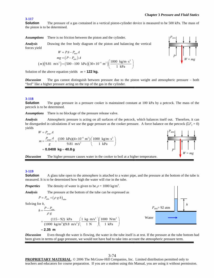
Chapter 3 Pressure and Fluid Statics
PROPRIETARY MATERIAL. © 2006 The McGraw-Hill Companies, Inc. Limited distribution permitted only to teachers and educators for course preparation. If you are a student using this Manual, you are using it without permission.
3-74
3-117 Solution The pressure of a gas contained in a vertical piston-cylinder device is measured to be 500 kPa. The mass of the piston is to be determined.
Assumptions There is no friction between the piston and the cylinder.
Analysis Drawing the free body diagram of the piston and balancing the vertical forces yield
( )( )( ) ( )( )
atm
atm 22 4 2 1000 kg/m s9.81 m/s 500 100 kPa 30 10 m
1 kPa
W PA P Amg P P A
m −
= −
= −⎛ ⎞⋅
= − × ⎜ ⎟⎝ ⎠
Solution of the above equation yields m = 122 kg. Discussion The gas cannot distinguish between pressure due to the piston weight and atmospheric pressure – both “feel” like a higher pressure acting on the top of the gas in the cylinder.
3-118 Solution The gage pressure in a pressure cooker is maintained constant at 100 kPa by a petcock. The mass of the petcock is to be determined.
Assumptions There is no blockage of the pressure release valve.
Analysis Atmospheric pressure is acting on all surfaces of the petcock, which balances itself out. Therefore, it can be disregarded in calculations if we use the gage pressure as the cooker pressure. A force balance on the petcock (ΣFy = 0) yields
6 2 2
2
(100 kPa)(4 10 m ) 1000 kg/m s1 kPa9.81 m/s
gage
gage
W P A
P Am
g
−
=
⎛ ⎞× ⋅= = ⎜ ⎟
⎝ ⎠= =0.0408 kg 40.8 g
Discussion The higher pressure causes water in the cooker to boil at a higher temperature.
3-119 Solution A glass tube open to the atmosphere is attached to a water pipe, and the pressure at the bottom of the tube is measured. It is to be determined how high the water will rise in the tube.
Properties The density of water is given to be ρ = 1000 kg/m3.
Analysis The pressure at the bottom of the tube can be expressed as ( )atm tube
P P g hρ= +
Solving for h,
atm
2 2
3 2
(115 92) kPa 1 kg m/s 1000 N/m1 N 1 kPa(1000 kg/m )(9.8 m/s )
P Ph
gρ−
=
⎛ ⎞⎛ ⎞− ⋅= ⎜ ⎟⎜ ⎟
⎝ ⎠⎝ ⎠= 2.35 m
Discussion Even though the water is flowing, the water in the tube itself is at rest. If the pressure at the tube bottom had been given in terms of gage pressure, we would not have had to take into account the atmospheric pressure term.
W = mg
Patm
P
W = mg
Patm
P
h Patm= 92 atm
Water
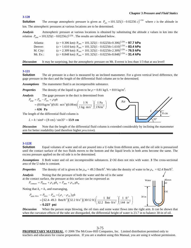
Chapter 3 Pressure and Fluid Statics
PROPRIETARY MATERIAL. © 2006 The McGraw-Hill Companies, Inc. Limited distribution permitted only to teachers and educators for course preparation. If you are a student using this Manual, you are using it without permission.
3-75
3-120 Solution The average atmospheric pressure is given as ( )5 256
atm 101 325 1 0 02256 .P . . z= − where z is the altitude in km. The atmospheric pressures at various locations are to be determined.
Analysis Atmospheric pressure at various locations is obtained by substituting the altitude z values in km into the relation P zatm = −101325 1 0 02256 5 256. ( . ) . . The results are tabulated below.
Atlanta: (z = 0.306 km): Patm = 101.325(1 - 0.02256×0.306)5.256 = 97.7 kPa Denver: (z = 1.610 km): Patm = 101.325(1 - 0.02256×1.610)5.256 = 83.4 kPa M. City: (z = 2.309 km): Patm = 101.325(1 - 0.02256×2.309)5.256 = 76.5 kPa Mt. Ev.: (z = 8.848 km): Patm = 101.325(1 - 0.02256×8.848)5.256 = 31.4 kPa Discussion It may be surprising, but the atmospheric pressure on Mt. Everest is less than 1/3 that at sea level!
3-121 Solution The air pressure in a duct is measured by an inclined manometer. For a given vertical level difference, the gage pressure in the duct and the length of the differential fluid column are to be determined.
Assumptions The manometer fluid is an incompressible substance.
Properties The density of the liquid is given to be ρ = 0.81 kg/L = 810 kg/m3.
Analysis The gage pressure in the duct is determined from
gage abs atm
3 22 2
1 N 1 Pa(810 kg/m )(9.81 m/s )(0.08m)1 kg m/s 1N/m
P P P ghρ= − =⎛ ⎞⎛ ⎞
= ⎜ ⎟⎜ ⎟⋅⎝ ⎠⎝ ⎠= 636 Pa
The length of the differential fluid column is
( )sin 8 cm sin35L h / /θ= = ° = 13.9 cm
Discussion Note that the length of the differential fluid column is extended considerably by inclining the manometer arm for better readability (and therefore higher precision).
3-122E Solution Equal volumes of water and oil are poured into a U-tube from different arms, and the oil side is pressurized until the contact surface of the two fluids moves to the bottom and the liquid levels in both arms become the same. The excess pressure applied on the oil side is to be determined.
Assumptions 1 Both water and oil are incompressible substances. 2 Oil does not mix with water. 3 The cross-sectional area of the U-tube is constant.
Properties The density of oil is given to be ρoil = 49.3 lbm/ft3. We take the density of water to be ρw = 62.4 lbm/ft3.
Analysis Noting that the pressure of both the water and the oil is the same at the contact surface, the pressure at this surface can be expressed as wwatmaablowcontact ghPghPP ρρ +=+=
Noting that ha = hw and rearranging,
( )
( )( ) ( )gage, blow blow atm oil 2
3 22 2
1 lbf 1 ft62.4- 49.3 lbm/ft 32 2 ft/s 30/12 ft32.2 lbm ft/s 144 in
wP P P gh.
ρ ρ= − = −⎛ ⎞⎛ ⎞
= ⎜ ⎟⎜ ⎟⋅⎝ ⎠⎝ ⎠= 0.227 psi
Discussion When the person stops blowing, the oil rises and some water flows into the right arm. It can be shown that when the curvature effects of the tube are disregarded, the differential height of water is 23.7 in to balance 30-in of oil.
Air
35°
8 cm L
30 in
Blown air
Water
Oil
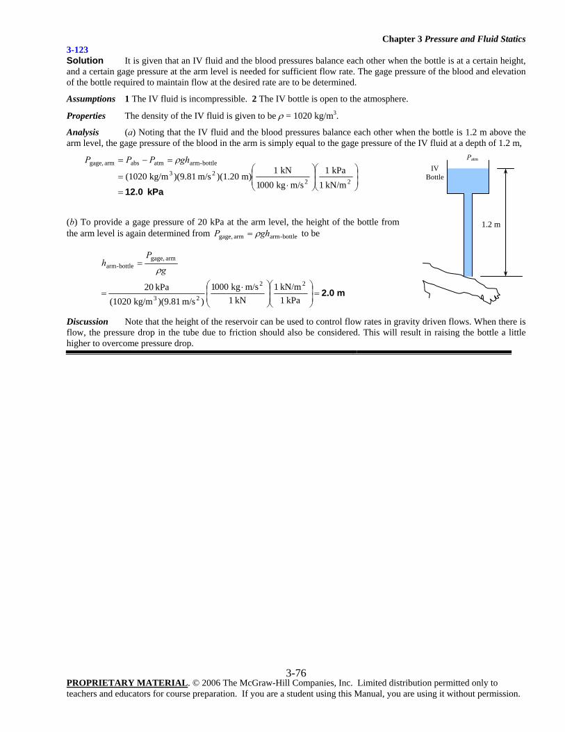
Chapter 3 Pressure and Fluid Statics
PROPRIETARY MATERIAL. © 2006 The McGraw-Hill Companies, Inc. Limited distribution permitted only to teachers and educators for course preparation. If you are a student using this Manual, you are using it without permission.
3-76
3-123 Solution It is given that an IV fluid and the blood pressures balance each other when the bottle is at a certain height, and a certain gage pressure at the arm level is needed for sufficient flow rate. The gage pressure of the blood and elevation of the bottle required to maintain flow at the desired rate are to be determined.
Assumptions 1 The IV fluid is incompressible. 2 The IV bottle is open to the atmosphere.
Properties The density of the IV fluid is given to be ρ = 1020 kg/m3.
Analysis (a) Noting that the IV fluid and the blood pressures balance each other when the bottle is 1.2 m above the arm level, the gage pressure of the blood in the arm is simply equal to the gage pressure of the IV fluid at a depth of 1.2 m,
Pak 12.0=⎟⎟⎠
⎞⎜⎜⎝
⎛⎟⎟⎠
⎞⎜⎜⎝
⎛
⋅=
=−=
2223
bottle-armatmabsarm gage,
kN/m 1kPa 1
m/skg 0001kN 1
m) )(1.20m/s )(9.81kg/m (1020
ghPPP ρ
(b) To provide a gage pressure of 20 kPa at the arm level, the height of the bottle from the arm level is again determined from bottle-armarm gage, ghP ρ= to be
m 2.0=⎟
⎟⎠
⎞⎜⎜⎝
⎛⎟⎟⎠
⎞⎜⎜⎝
⎛ ⋅=
=
kPa 1kN/m 1
kN 1m/skg 0001
)m/s )(9.81kg/m (1020kPa 20 22
23
arm gage,bottle-arm g
Ph
ρ
Discussion Note that the height of the reservoir can be used to control flow rates in gravity driven flows. When there is flow, the pressure drop in the tube due to friction should also be considered. This will result in raising the bottle a little higher to overcome pressure drop.
1.2 m
Patm IV
Bottle
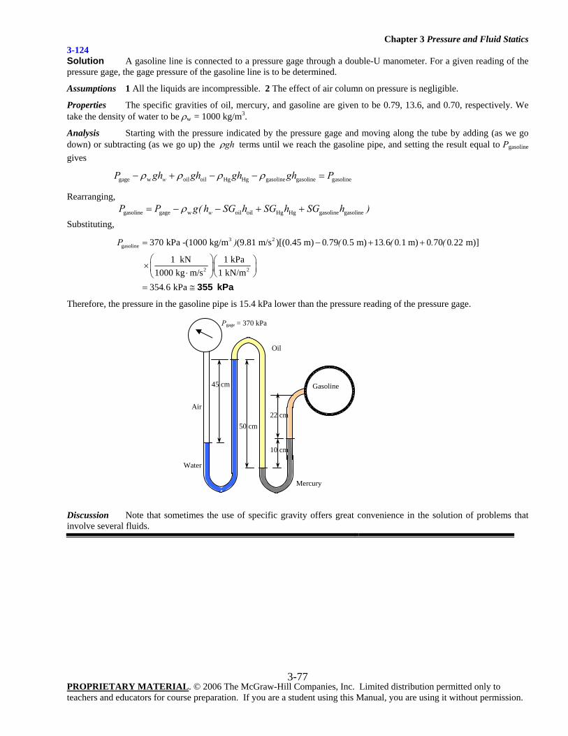
Chapter 3 Pressure and Fluid Statics
PROPRIETARY MATERIAL. © 2006 The McGraw-Hill Companies, Inc. Limited distribution permitted only to teachers and educators for course preparation. If you are a student using this Manual, you are using it without permission.
3-77
3-124 Solution A gasoline line is connected to a pressure gage through a double-U manometer. For a given reading of the pressure gage, the gage pressure of the gasoline line is to be determined.
Assumptions 1 All the liquids are incompressible. 2 The effect of air column on pressure is negligible.
Properties The specific gravities of oil, mercury, and gasoline are given to be 0.79, 13.6, and 0.70, respectively. We take the density of water to be ρw = 1000 kg/m3.
Analysis Starting with the pressure indicated by the pressure gage and moving along the tube by adding (as we go down) or subtracting (as we go up) the ghρ terms until we reach the gasoline pipe, and setting the result equal to Pgasoline gives
gage w oil oil Hg Hg gasoline gasoline gasolinewP gh gh gh gh Pρ ρ ρ ρ− + − − =
Rearranging, gasoline gage w oil oil Hg Hg gasoline gasolinewP P g( h SG h SG h SG h )ρ= − − + +
Substituting, 3 2
gasoline
2 2
370 kPa -(1000 kg/m (9.81 m/s )[(0.45 m) 0 79 0 5 m) 13 6 0 1 m) 0 70 0 22 m)]
1 kN 1 kPa1000 kg m/s 1 kN/m
354 6 kPa
P ) . ( . . ( . . ( .
.
= − + +
⎛ ⎞⎛ ⎞×⎜ ⎟⎜ ⎟⋅ ⎝ ⎠⎝ ⎠= ≅ 355 kPa
Therefore, the pressure in the gasoline pipe is 15.4 kPa lower than the pressure reading of the pressure gage.
Discussion Note that sometimes the use of specific gravity offers great convenience in the solution of problems that involve several fluids.
45 cm
Gasoline
22 cm
Mercury
Water
10 cm
Oil
50 cm
Air
Pgage = 370 kPa
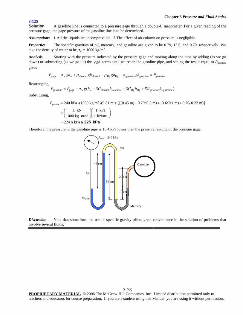
Chapter 3 Pressure and Fluid Statics
PROPRIETARY MATERIAL. © 2006 The McGraw-Hill Companies, Inc. Limited distribution permitted only to teachers and educators for course preparation. If you are a student using this Manual, you are using it without permission.
3-78
3-125 Solution A gasoline line is connected to a pressure gage through a double-U manometer. For a given reading of the pressure gage, the gage pressure of the gasoline line is to be determined.
Assumptions 1 All the liquids are incompressible. 2 The effect of air column on pressure is negligible.
Properties The specific gravities of oil, mercury, and gasoline are given to be 0.79, 13.6, and 0.70, respectively. We take the density of water to be ρw = 1000 kg/m3.
Analysis Starting with the pressure indicated by the pressure gage and moving along the tube by adding (as we go down) or subtracting (as we go up) the ghρ terms until we reach the gasoline pipe, and setting the result equal to Pgasoline gives
gasolinegasolinegasolineHgHgalcoholalcoholw PghghghghP wgage =−−+− ρρρρ
Rearranging, )( gasolines,gasolineHgHgalcohols,alcoholwgagegasoline hSGhSGhSGhgPP w ++−−= ρ
Substituting, 3 2
gasoline
2 2
240 kPa -(1000 kg/m (9.81 m/s )[(0.45 m) 0 79 0 5 m) 13 6 0 1 m) 0 70 0 22 m)]
1 kN 1 kPa1000 kg m/s 1 kN/m
224 6 kPa
P ) . ( . . ( . . ( .
.
= − + +
⎛ ⎞⎛ ⎞×⎜ ⎟⎜ ⎟⋅ ⎝ ⎠⎝ ⎠= ≅ 225 kPa
Therefore, the pressure in the gasoline pipe is 15.4 kPa lower than the pressure reading of the pressure gage.
Discussion Note that sometimes the use of specific gravity offers great convenience in the solution of problems that involve several fluids.
45 cm
Gasoline
22 cm
Mercury
Water
10 cm
Oil
50 cm
Air
Pgage = 240 kPa
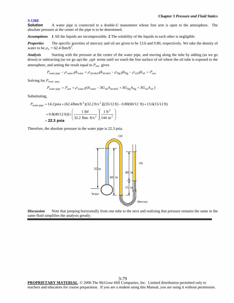
Chapter 3 Pressure and Fluid Statics
PROPRIETARY MATERIAL. © 2006 The McGraw-Hill Companies, Inc. Limited distribution permitted only to teachers and educators for course preparation. If you are a student using this Manual, you are using it without permission.
3-79
3-126E Solution A water pipe is connected to a double-U manometer whose free arm is open to the atmosphere. The absolute pressure at the center of the pipe is to be determined.
Assumptions 1 All the liquids are incompressible. 2 The solubility of the liquids in each other is negligible.
Properties The specific gravities of mercury and oil are given to be 13.6 and 0.80, respectively. We take the density of water to be ρw = 62.4 lbm/ft3.
Analysis Starting with the pressure at the center of the water pipe, and moving along the tube by adding (as we go down) or subtracting (as we go up) the ghρ terms until we reach the free surface of oil where the oil tube is exposed to the atmosphere, and setting the result equal to Patm gives
atmPghghghghP =−−+− oiloilHgHgalcoholalcoholwaterwaterpipewater ρρρρ
Solving for Pwater pipe,
)( oiloilHgHgalcoholoilwaterwaterwater pipe hSGhSGhSGhgPP atm ++−+= ρ
Substituting,
psia 22.3=⎟⎟⎠
⎞⎜⎜⎝
⎛⎟⎟⎠
⎞⎜⎜⎝
⎛
⋅×+
+−+=
2
2
2
23pipewater
in 144ft 1
ft/slbm 32.2lbf 1
ft)] (40/128.0
ft) (15/126.13ft) (60/1280.0ft) )[(35/12ft/s 2.32()lbm/ft(62.4psia14.2P
Therefore, the absolute pressure in the water pipe is 22.3 psia.
Discussion Note that jumping horizontally from one tube to the next and realizing that pressure remains the same in the same fluid simplifies the analysis greatly.
35 in
Oil
40 in
Mercury
15 in
Oil
60 in
Water
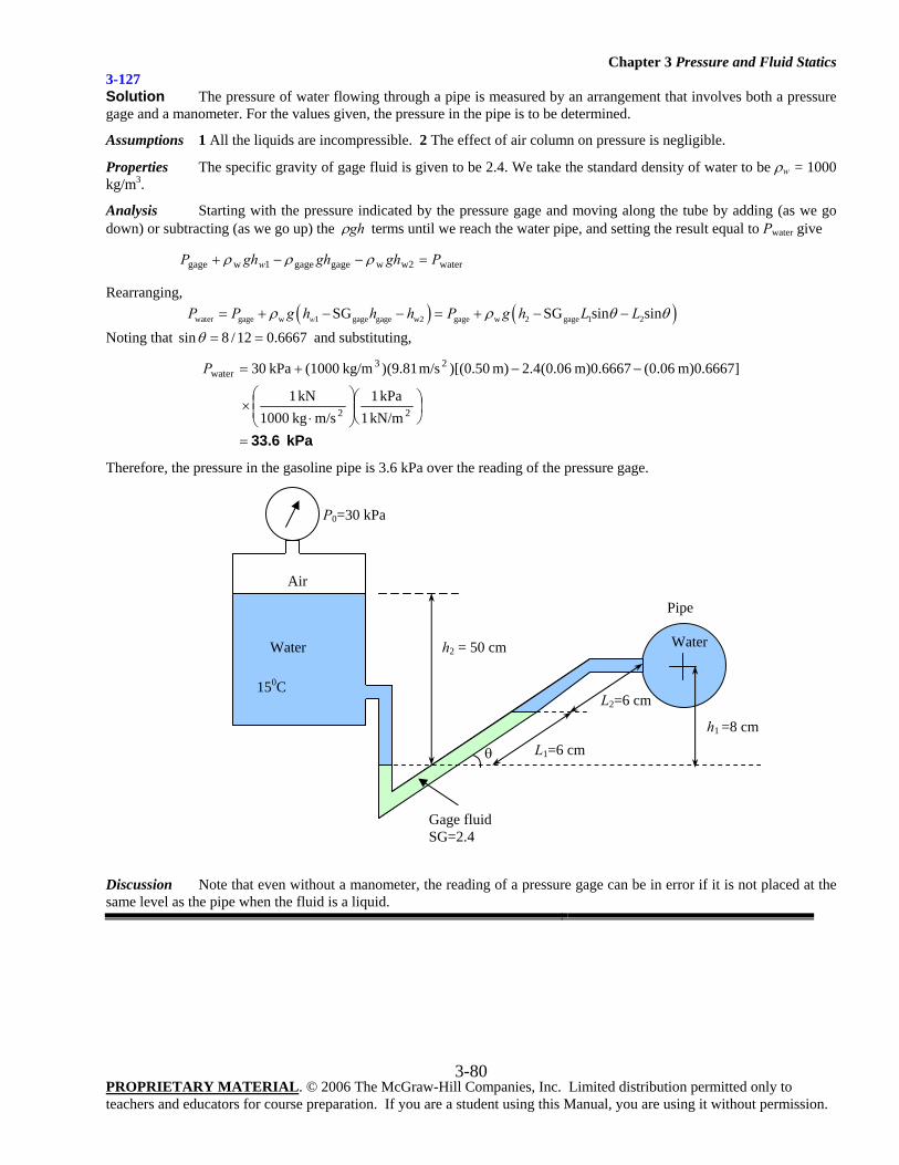
Chapter 3 Pressure and Fluid Statics
PROPRIETARY MATERIAL. © 2006 The McGraw-Hill Companies, Inc. Limited distribution permitted only to teachers and educators for course preparation. If you are a student using this Manual, you are using it without permission.
3-80
3-127 Solution The pressure of water flowing through a pipe is measured by an arrangement that involves both a pressure gage and a manometer. For the values given, the pressure in the pipe is to be determined.
Assumptions 1 All the liquids are incompressible. 2 The effect of air column on pressure is negligible.
Properties The specific gravity of gage fluid is given to be 2.4. We take the standard density of water to be ρw = 1000 kg/m3.
Analysis Starting with the pressure indicated by the pressure gage and moving along the tube by adding (as we go down) or subtracting (as we go up) the ghρ terms until we reach the water pipe, and setting the result equal to Pwater give
waterw2wgagegage1wgage PghghghP w =−−+ ρρρ
Rearranging, ( ) ( )water gage w 1 gage gage w2 gage w 2 gage 1 2SG SG sin sinwP P g h h h P g h L Lρ ρ θ θ= + − − = + − −
Noting that 6667.012/8sin ==θ and substituting,
kPa 33.6=
⎟⎠⎞
⎜⎝⎛
⎟⎟⎠
⎞⎜⎜⎝
⎛
⋅×
−−+=
22
23water
kN/m1 kPa1
m/s kg1000 kN1
m)0.6667] 06.0(m)0.6667 06.0(4.2m) )[(0.50m/s (9.81) kg/m(1000 kPa 30P
Therefore, the pressure in the gasoline pipe is 3.6 kPa over the reading of the pressure gage.
Discussion Note that even without a manometer, the reading of a pressure gage can be in error if it is not placed at the same level as the pipe when the fluid is a liquid.
P0=30 kPa
Water Water
Air
Gage fluid SG=2.4
h2 = 50 cm
L1=6 cm
L2=6 cm
h1 =8 cm
Pipe
150C
θ
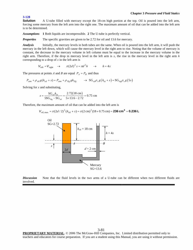
Chapter 3 Pressure and Fluid Statics
PROPRIETARY MATERIAL. © 2006 The McGraw-Hill Companies, Inc. Limited distribution permitted only to teachers and educators for course preparation. If you are a student using this Manual, you are using it without permission.
3-81
3-128 Solution A U-tube filled with mercury except the 18-cm high portion at the top. Oil is poured into the left arm, forcing some mercury from the left arm into the right one. The maximum amount of oil that can be added into the left arm is to be determined.
Assumptions 1 Both liquids are incompressible. 2 The U-tube is perfectly vertical.
Properties The specific gravities are given to be 2.72 for oil and 13.6 for mercury.
Analysis Initially, the mercury levels in both tubes are the same. When oil is poured into the left arm, it will push the mercury in the left down, which will cause the mercury level in the right arm to rise. Noting that the volume of mercury is constant, the decrease in the mercury volume in left column must be equal to the increase in the mercury volume in the right arm. Therefore, if the drop in mercury level in the left arm is x, the rise in the mercury level in the right arm h corresponding to a drop of x in the left arm is
rightleft VV = → hdxd 22)2( ππ = → xh 4=
The pressures at points A and B are equal BA PP = and thus
HgHgatmoilatm ghPxhgP ρρ +=++ )(oil → ( ) ( )oil oil HgSG SG 5w wg h x g xρ ρ+ =
Solving for x and substituting,
( )oil oil
Hg oil
2 72 18 cmSG0.75 cm
5SG SG 5 13 6 2 72.h
x. .
= = =− × −
Therefore, the maximum amount of oil that can be added into the left arm is
L 0.236cm 236 3 ==+=+= cm) 75.018(cm) 2()()2/2( 2oil
2max oil, ππ xhdV
Discussion Note that the fluid levels in the two arms of a U-tube can be different when two different fluids are involved.
Mercury SG=13.6
hoil = 18 cm
A Bx
h = 4x
d = 2 cm2d
Oil SG=2.72
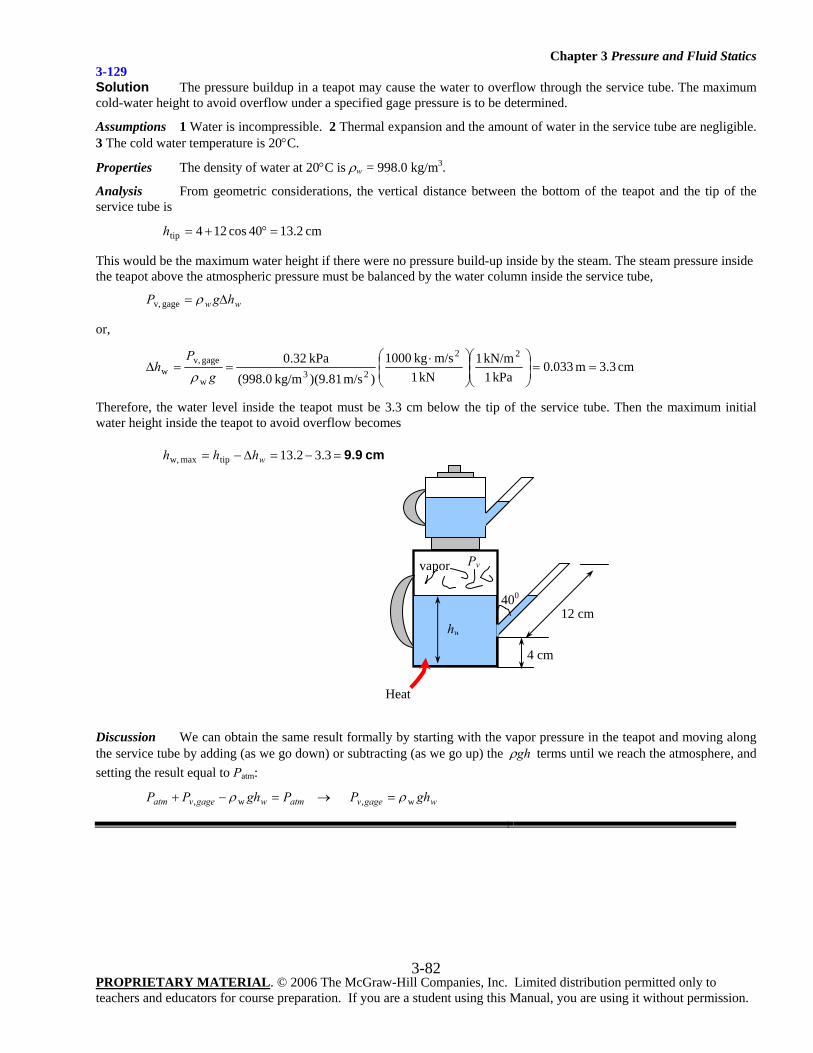
Chapter 3 Pressure and Fluid Statics
PROPRIETARY MATERIAL. © 2006 The McGraw-Hill Companies, Inc. Limited distribution permitted only to teachers and educators for course preparation. If you are a student using this Manual, you are using it without permission.
3-82
3-129 Solution The pressure buildup in a teapot may cause the water to overflow through the service tube. The maximum cold-water height to avoid overflow under a specified gage pressure is to be determined.
Assumptions 1 Water is incompressible. 2 Thermal expansion and the amount of water in the service tube are negligible. 3 The cold water temperature is 20°C.
Properties The density of water at 20°C is ρw = 998.0 kg/m3.
Analysis From geometric considerations, the vertical distance between the bottom of the teapot and the tip of the service tube is
cm 2.1340cos124tip =°+=h
This would be the maximum water height if there were no pressure build-up inside by the steam. The steam pressure inside the teapot above the atmospheric pressure must be balanced by the water column inside the service tube,
ww hgP Δ= ρgage v,
or,
cm 3.3m 033.0kPa 1
kN/m 1kN 1
m/skg 1000)m/s (9.81)kg/m (998.0
kPa 32.0 22
23w
gage v,w ==⎟
⎟⎠
⎞⎜⎜⎝
⎛⎟⎟⎠
⎞⎜⎜⎝
⎛ ⋅==Δ
gP
hρ
Therefore, the water level inside the teapot must be 3.3 cm below the tip of the service tube. Then the maximum initial water height inside the teapot to avoid overflow becomes
cm 9.9=−=Δ−= 3.32.13tipmax w, whhh
Discussion We can obtain the same result formally by starting with the vapor pressure in the teapot and moving along the service tube by adding (as we go down) or subtracting (as we go up) the ghρ terms until we reach the atmosphere, and setting the result equal to Patm:
atmwgagevatm PghPP =−+ w, ρ → wgagev ghP w, ρ=
Heat
vapor
12 cm 400
4 cm
Pv
hw
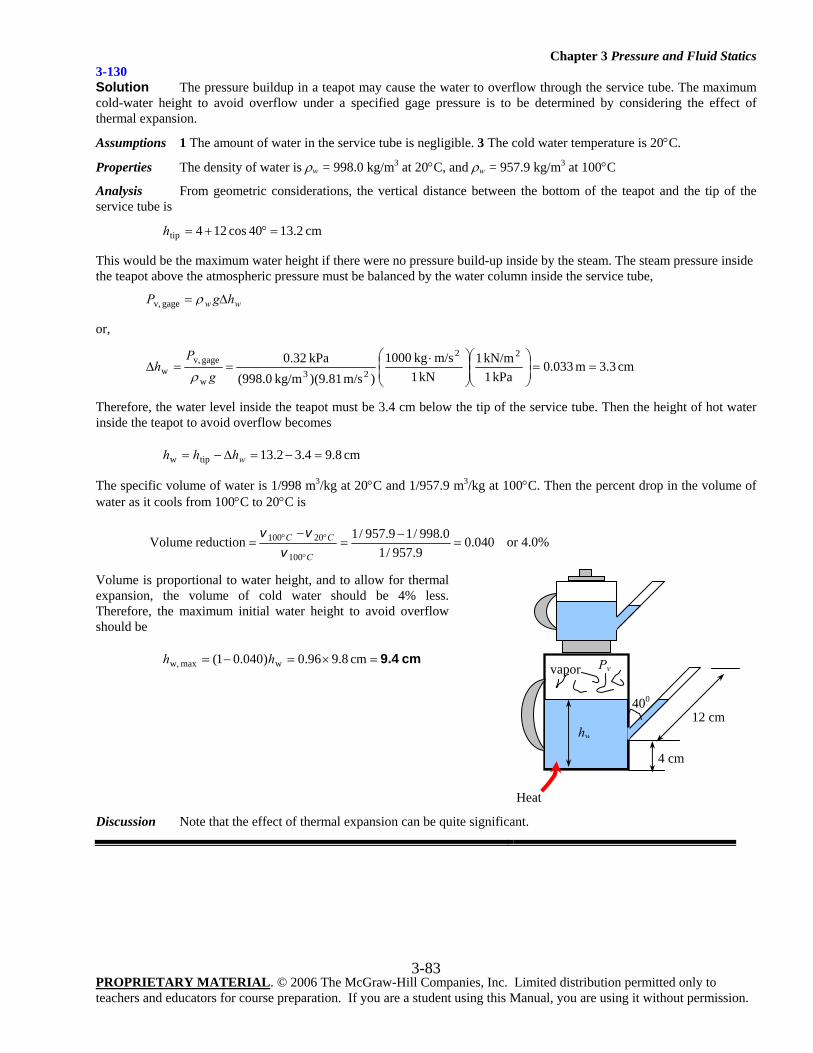
Chapter 3 Pressure and Fluid Statics
PROPRIETARY MATERIAL. © 2006 The McGraw-Hill Companies, Inc. Limited distribution permitted only to teachers and educators for course preparation. If you are a student using this Manual, you are using it without permission.
3-83
3-130 Solution The pressure buildup in a teapot may cause the water to overflow through the service tube. The maximum cold-water height to avoid overflow under a specified gage pressure is to be determined by considering the effect of thermal expansion.
Assumptions 1 The amount of water in the service tube is negligible. 3 The cold water temperature is 20°C.
Properties The density of water is ρw = 998.0 kg/m3 at 20°C, and ρw = 957.9 kg/m3 at 100°C
Analysis From geometric considerations, the vertical distance between the bottom of the teapot and the tip of the service tube is
cm 2.1340cos124tip =°+=h
This would be the maximum water height if there were no pressure build-up inside by the steam. The steam pressure inside the teapot above the atmospheric pressure must be balanced by the water column inside the service tube,
ww hgP Δ= ρgage v,
or,
cm 3.3m 033.0kPa 1
kN/m 1kN 1
m/skg 1000)m/s (9.81)kg/m (998.0
kPa 32.0 22
23w
gage v,w ==⎟
⎟⎠
⎞⎜⎜⎝
⎛⎟⎟⎠
⎞⎜⎜⎝
⎛ ⋅==Δ
gP
hρ
Therefore, the water level inside the teapot must be 3.4 cm below the tip of the service tube. Then the height of hot water inside the teapot to avoid overflow becomes
cm 8.94.32.13tipw =−=Δ−= whhh
The specific volume of water is 1/998 m3/kg at 20°C and 1/957.9 m3/kg at 100°C. Then the percent drop in the volume of water as it cools from 100°C to 20°C is
040.09.957/1
0.998/19.957/1 reductionVolume100
20100 =−
=−
=°
°°
C
CC
vvv
or 4.0%
Volume is proportional to water height, and to allow for thermal expansion, the volume of cold water should be 4% less. Therefore, the maximum initial water height to avoid overflow should be
cm 9.4=×=−= cm 8.996.0)040.01( wmax w, hh
Discussion Note that the effect of thermal expansion can be quite significant.
Heat
vapor
12 cm 400
4 cm
Pv
hw
Chapter 3 Pressure and Fluid Statics
PROPRIETARY MATERIAL. © 2006 The McGraw-Hill Companies, Inc. Limited distribution permitted only to teachers and educators for course preparation. If you are a student using this Manual, you are using it without permission.
3-84
3-131 Solution The temperature of the atmosphere varies with altitude z as zTT β−= 0 , while the gravitational
acceleration varies by 20 )320,370,6/1/()( zgzg += . Relations for the variation of pressure in atmosphere are to be
obtained (a) by ignoring and (b) by considering the variation of g with altitude.
Assumptions The air in the troposphere behaves as an ideal gas.
Analysis (a) Pressure change across a differential fluid layer of thickness dz in the vertical z direction is gdzdP ρ−=
From the ideal gas relation, the air density can be expressed as )( 0 zTR
PRTP
βρ
−== . Then,
gdzzTR
PdP)( 0 β−
−=
Separating variables and integrating from z = 0 where 0PP = to z = z where P = P,
)( 000 zTR
gdzP
dP zP
P β−−= ∫∫
Performing the integrations.
0
0
0lnln
TzT
Rg
PP β
β−
=
Rearranging, the desired relation for atmospheric pressure for the case of constant g becomes
Rg
TzPP
ββ⎟⎟⎠
⎞⎜⎜⎝
⎛−=
00 1
(b) When the variation of g with altitude is considered, the procedure remains the same but the expressions become more complicated,
dzz
gzTR
PdP 20
0 )320,370,6/1()( +−−=
β
Separating variables and integrating from z = 0 where 0PP = to z = z where P = P,
20
0
0 )320,370,6/1)((0 zzTRdzg
PdP zP
P +−−= ∫∫ β
Performing the integrations,
z
PP zT
kzkTkzkTR
gP
002
00
0 1ln)/1(
1)1)(/1(
1ln0 ββββ −
++
−++
=
where R = 287 J/kg⋅K = 287 m2/s2⋅K is the gas constant of air. After some manipulations, we obtain
⎥⎥⎦
⎤
⎢⎢⎣
⎡⎟⎟⎠
⎞⎜⎜⎝
⎛−
++
+++
−=000
00 /1
1ln/1
1/11
1)(
expTz
kzkTkzkTR
gPP
βββ
where T0 = 288.15 K, β = 0.0065 K/m, g0 = 9.807 m/s2, k = 1/6,370,320 m-1, and z is the elevation in m..
Discussion When performing the integration in part (b), the following expression from integral tables is used, together with a transformation of variable zTx β−= 0 ,
xbxa
abxaabxaxdx +
−+
=+∫ ln1
)(1
)( 22
Also, for z = 11,000 m, for example, the relations in (a) and (b) give 22.62 and 22.69 kPa, respectively.
Chapter 3 Pressure and Fluid Statics
PROPRIETARY MATERIAL. © 2006 The McGraw-Hill Companies, Inc. Limited distribution permitted only to teachers and educators for course preparation. If you are a student using this Manual, you are using it without permission.
3-85
3-132 Solution The variation of pressure with density in a thick gas layer is given. A relation is to be obtained for pressure as a function of elevation z.
Assumptions The property relation nCP ρ= is valid over the entire region considered.
Analysis The pressure change across a differential fluid layer of thickness dz in the vertical z direction is given as,
gdzdP ρ−=
Also, the relation nCP ρ= can be expressed as nn PPC 00 // ρρ == , and thus
nPP /100 )/(ρρ =
Substituting,
dzPPgdP n/100 )/(ρ−=
Separating variables and integrating from z = 0 where nCPP 00 ρ== to z = z where P = P,
dzgdPPPzP
P
n ∫∫ −=−
00
/10
0
)/( ρ
Performing the integrations.
gzn
PPP
P
P
n
0
1/10
0
01/1
)/(ρ−=
+−
+−
→ 0
0/)1(
0
11P
gzn
nPP
nnρ−
−=−⎟⎟⎠
⎞⎜⎜⎝
⎛−
Solving for P,
)1/(
0
00
11−
⎟⎟⎠
⎞⎜⎜⎝
⎛ −−=
nn
Pgz
nnPP
ρ
which is the desired relation.
Discussion The final result could be expressed in various forms. The form given is very convenient for calculations as it facilitates unit cancellations and reduces the chance of error.
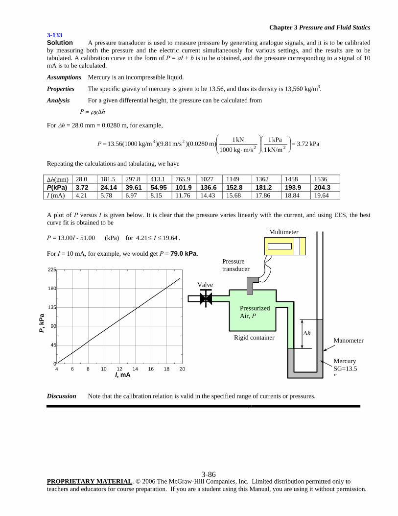
Chapter 3 Pressure and Fluid Statics
PROPRIETARY MATERIAL. © 2006 The McGraw-Hill Companies, Inc. Limited distribution permitted only to teachers and educators for course preparation. If you are a student using this Manual, you are using it without permission.
3-86
3-133 Solution A pressure transducer is used to measure pressure by generating analogue signals, and it is to be calibrated by measuring both the pressure and the electric current simultaneously for various settings, and the results are to be tabulated. A calibration curve in the form of P = aI + b is to be obtained, and the pressure corresponding to a signal of 10 mA is to be calculated.
Assumptions Mercury is an incompressible liquid.
Properties The specific gravity of mercury is given to be 13.56, and thus its density is 13,560 kg/m3.
Analysis For a given differential height, the pressure can be calculated from
hgP Δ= ρ
For Δh = 28.0 mm = 0.0280 m, for example,
kPa 72.3kN/m 1
kPa 1m/skg 1000
kN 1m) )(0.0280m/s (9.81)kg/m (100056.1322
23 =⎟⎠
⎞⎜⎝
⎛⎟⎟⎠
⎞⎜⎜⎝
⎛
⋅=P
Repeating the calculations and tabulating, we have Δh(mm) 28.0 181.5 297.8 413.1 765.9 1027 1149 1362 1458 1536 P(kPa) 3.72 24.14 39.61 54.95 101.9 136.6 152.8 181.2 193.9 204.3 I (mA) 4.21 5.78 6.97 8.15 11.76 14.43 15.68 17.86 18.84 19.64
A plot of P versus I is given below. It is clear that the pressure varies linearly with the current, and using EES, the best curve fit is obtained to be P = 13.00I - 51.00 (kPa) for 64.1921.4 ≤≤ I . For I = 10 mA, for example, we would get P = 79.0 kPa.
Discussion Note that the calibration relation is valid in the specified range of currents or pressures.
4 6 8 10 12 14 16 18 200
45
90
135
180
225
I, mA
P, k
Pa
Multimeter
Δh
Pressurized Air, P
Pressure transducer
Valve
Rigid container Manometer
Mercury SG=13.56
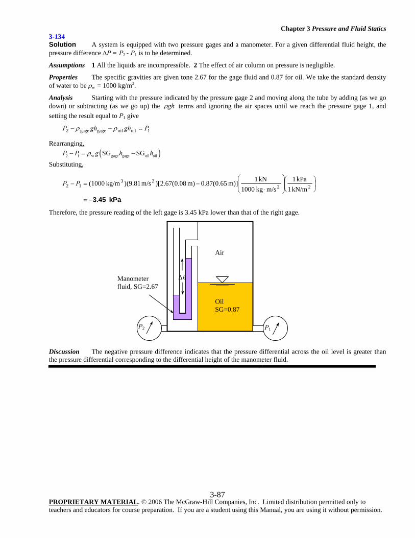
Chapter 3 Pressure and Fluid Statics
PROPRIETARY MATERIAL. © 2006 The McGraw-Hill Companies, Inc. Limited distribution permitted only to teachers and educators for course preparation. If you are a student using this Manual, you are using it without permission.
3-87
3-134 Solution A system is equipped with two pressure gages and a manometer. For a given differential fluid height, the pressure difference ΔP = P2 - P1 is to be determined.
Assumptions 1 All the liquids are incompressible. 2 The effect of air column on pressure is negligible.
Properties The specific gravities are given tone 2.67 for the gage fluid and 0.87 for oil. We take the standard density of water to be ρw = 1000 kg/m3.
Analysis Starting with the pressure indicated by the pressure gage 2 and moving along the tube by adding (as we go down) or subtracting (as we go up) the ghρ terms and ignoring the air spaces until we reach the pressure gage 1, and setting the result equal to P1 give
1oiloilgagegage2 PghghP =+− ρρ
Rearranging, ( )2 1 w gage gage oil oilSG SGP P g h hρ− = − Substituting,
kPa 3.45−=
⎟⎠⎞
⎜⎝⎛
⎟⎟⎠
⎞⎜⎜⎝
⎛
⋅−=− 22
2312 kN/m1
kPa1m/s kg1000
kN1m)] 65.0(87.0m) 08.0(67.2)[m/s (9.81) kg/m(1000PP
Therefore, the pressure reading of the left gage is 3.45 kPa lower than that of the right gage.
Discussion The negative pressure difference indicates that the pressure differential across the oil level is greater than the pressure differential corresponding to the differential height of the manometer fluid.
Δh
Air
Oil SG=0.87
Manometer fluid, SG=2.67
P2 P1
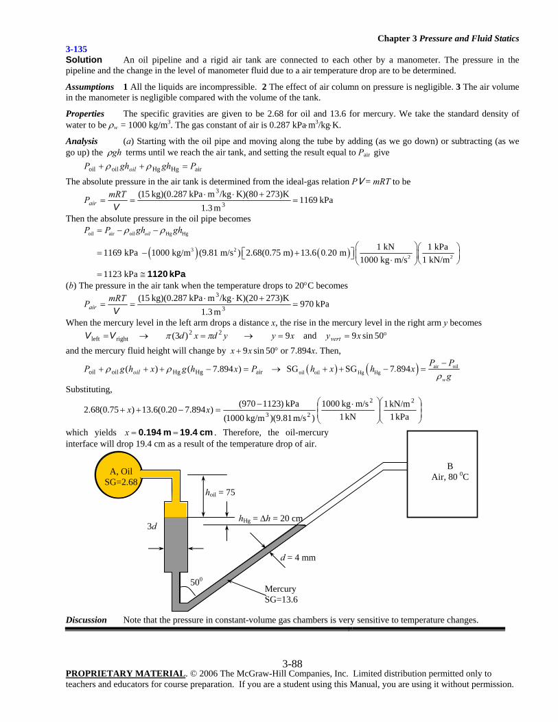
Chapter 3 Pressure and Fluid Statics
PROPRIETARY MATERIAL. © 2006 The McGraw-Hill Companies, Inc. Limited distribution permitted only to teachers and educators for course preparation. If you are a student using this Manual, you are using it without permission.
3-88
3-135 Solution An oil pipeline and a rigid air tank are connected to each other by a manometer. The pressure in the pipeline and the change in the level of manometer fluid due to a air temperature drop are to be determined.
Assumptions 1 All the liquids are incompressible. 2 The effect of air column on pressure is negligible. 3 The air volume in the manometer is negligible compared with the volume of the tank.
Properties The specific gravities are given to be 2.68 for oil and 13.6 for mercury. We take the standard density of water to be ρw = 1000 kg/m3. The gas constant of air is 0.287 kPa⋅m3/kg⋅K.
Analysis (a) Starting with the oil pipe and moving along the tube by adding (as we go down) or subtracting (as we go up) the ghρ terms until we reach the air tank, and setting the result equal to Pair give airHgHgoiloil PghghP oil =++ ρρ
The absolute pressure in the air tank is determined from the ideal-gas relation PV = mRT to be
kPa1169m 3.1
273)KK)(80/kgm kPa kg)(0.28715(3
3=
+⋅⋅==
VmRTPair
Then the absolute pressure in the oil pipe becomes
( ) ( )
oil air oil Hg Hg
3 22 2
1 kN 1 kPa1169 kPa 1000 kg/m (9.81 m/s ) 2.68(0.75 m) 13.6 0 20 m1000 kg m/s 1 kN/m
1123 kPa
oilP P gh gh
.
ρ ρ= − −
⎛ ⎞⎛ ⎞= − +⎡ ⎤ ⎜ ⎟⎜ ⎟⎣ ⎦ ⋅ ⎝ ⎠⎝ ⎠= ≅ 1120 kPa
(b) The pressure in the air tank when the temperature drops to 20°C becomes
kPa970m 3.1
273)KK)(20/kgm kPa kg)(0.28715(3
3=
+⋅⋅==
VmRTPair
When the mercury level in the left arm drops a distance x, the rise in the mercury level in the right arm y becomes rightleft VV = → ydxd 22)3( ππ = → xy 9= and °= 50sin9xyvert and the mercury fluid height will change by °+ 50sin9xx or 7.894x. Then,
airHgHgoiloil )894.7()( PxhgxhgP oil =−+++ ρρ → ( ) ( ) air oiloil oil Hg HgSG SG 7 894
w
P Ph x h . x
gρ−
+ + − =
Substituting,
⎟⎟⎠
⎞⎜⎜⎝
⎛⎟⎟⎠
⎞⎜⎜⎝
⎛ ⋅−=−++
kPa 1kN/m 1
kN 1m/skg 1000
)m/s )(9.81kg/m 1000(kPa )1123970()894.720.0(6.13)75.0(68.2
22
23xx
which yields cm 19.4 m 0.194 ==x . Therefore, the oil-mercury interface will drop 19.4 cm as a result of the temperature drop of air.
Discussion Note that the pressure in constant-volume gas chambers is very sensitive to temperature changes.
A, Oil SG=2.68
B Air, 80 0C
hHg = Δh = 20 cm
Mercury SG=13.6
3d
d = 4 mm
hoil = 75
500
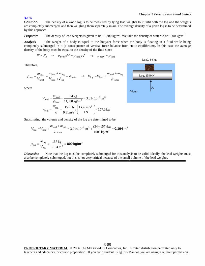
Chapter 3 Pressure and Fluid Statics
PROPRIETARY MATERIAL. © 2006 The McGraw-Hill Companies, Inc. Limited distribution permitted only to teachers and educators for course preparation. If you are a student using this Manual, you are using it without permission.
3-89
3-136 Solution The density of a wood log is to be measured by tying lead weights to it until both the log and the weights are completely submerged, and then weighing them separately in air. The average density of a given log is to be determined by this approach.
Properties The density of lead weights is given to be 11,300 kg/m3. We take the density of water to be 1000 kg/m3.
Analysis The weight of a body is equal to the buoyant force when the body is floating in a fluid while being completely submerged in it (a consequence of vertical force balance from static equilibrium). In this case the average density of the body must be equal to the density of the fluid since
fluidbodyfluidbody ρρρρ =→=→= VV ggFW B
Therefore,
water
logleadleadlogwater
loglead
loglead
total
total ρ
ρρmmmmm
ave+
+=→=+
+== VV
VVV
where
kg0.157
N 1m/s kg1
m/s 81.9N 1540
m 1001.3 kg/m300,11 kg34
2
2log
log
333
lead
leadlead
=⎟⎟⎠
⎞⎜⎜⎝
⎛ ⋅==
×=== −
gW
m
mρ
V
Substituting, the volume and density of the log are determined to be
33
33
water
logleadleadlog
kg/m 1000kg )15734(
m 1001.3 m 0.194=+
+×=+
+= −
ρ
mmVV
3kg/m 809===3
log
loglog
m 194.0kg 157
Vm
ρ
Discussion Note that the log must be completely submerged for this analysis to be valid. Ideally, the lead weights must also be completely submerged, but this is not very critical because of the small volume of the lead weights.
Lead, 34 kg
Log, 1540 N
FB
Water
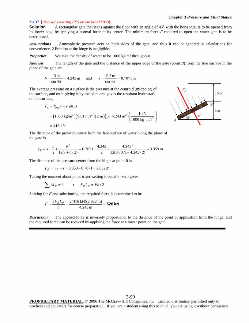
Chapter 3 Pressure and Fluid Statics
PROPRIETARY MATERIAL. © 2006 The McGraw-Hill Companies, Inc. Limited distribution permitted only to teachers and educators for course preparation. If you are a student using this Manual, you are using it without permission.
3-90
3-137 [Also solved using EES on enclosed DVD] Solution A rectangular gate that leans against the floor with an angle of 45° with the horizontal is to be opened from its lower edge by applying a normal force at its center. The minimum force F required to open the water gate is to be determined.
Assumptions 1 Atmospheric pressure acts on both sides of the gate, and thus it can be ignored in calculations for convenience. 2 Friction at the hinge is negligible.
Properties We take the density of water to be 1000 kg/m3 throughout.
Analysis The length of the gate and the distance of the upper edge of the gate (point B) from the free surface in the plane of the gate are
m 7071.045sinm 5.0 and m 243.4
45sinm 3
=°
==°
= sb
The average pressure on a surface is the pressure at the centroid (midpoint) of the surface, and multiplying it by the plate area gives the resultant hydrostatic on the surface,
( )( )( )( )avg
3 2 22
1 kN1000 kg/m 9 81 m/s 2 m 5 4.243 m1000 kg m/s
416 kN
R CF P A gh A
.
ρ= =
⎛ ⎞= × ⎜ ⎟⋅⎝ ⎠=
The distance of the pressure center from the free surface of water along the plane of the gate is
m 359.3
)2/243.47071.0(12243.4
2243.47071.0
)2/(122
22=
+++=
+++=
bsbbsyP
The distance of the pressure center from the hinge at point B is
m 652.27071.0359.3 =−=−= syL PP
Taking the moment about point B and setting it equal to zero gives
2/ 0 FbLFM PRB =→=∑
Solving for F and substituting, the required force is determined to be
kN 520===m 4.243
m) kN)(2.652 416(22b
LFF PR
Discussion The applied force is inversely proportional to the distance of the point of application from the hinge, and the required force can be reduced by applying the force at a lower point on the gate.
FR
F 45°
B
0.5 m
3 m
A
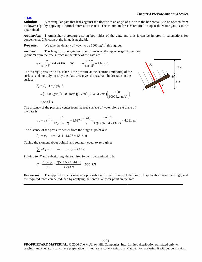
Chapter 3 Pressure and Fluid Statics
PROPRIETARY MATERIAL. © 2006 The McGraw-Hill Companies, Inc. Limited distribution permitted only to teachers and educators for course preparation. If you are a student using this Manual, you are using it without permission.
3-91
3-138 Solution A rectangular gate that leans against the floor with an angle of 45° with the horizontal is to be opened from its lower edge by applying a normal force at its center. The minimum force F required to open the water gate is to be determined.
Assumptions 1 Atmospheric pressure acts on both sides of the gate, and thus it can be ignored in calculations for convenience. 2 Friction at the hinge is negligible.
Properties We take the density of water to be 1000 kg/m3 throughout.
Analysis The length of the gate and the distance of the upper edge of the gate (point B) from the free surface in the plane of the gate are
m 697.145sinm 2.1and m 243.4
45sinm 3
=°
==°
= sb
The average pressure on a surface is the pressure at the centroid (midpoint) of the surface, and multiplying it by the plate area gives the resultant hydrostatic on the surface,
( )( )( )( )avg
3 2 22
1 kN1000 kg/m 9 81 m/s 2 7 m 5 4.243 m1000 kg m/s
562 kN
R CF P A gh A
. .
ρ= =
⎛ ⎞= × ⎜ ⎟⋅⎝ ⎠=
The distance of the pressure center from the free surface of water along the plane of the gate is
m 211.4)2/243.4697.1(12
243.42243.4697.1
)2/(122
22=
+++=
+++=
bsbbsyP
The distance of the pressure center from the hinge at point B is
m 514.2697.1211.4 =−=−= syL PP
Taking the moment about point B and setting it equal to zero gives
2/ 0 FbLFM PRB =→=∑
Solving for F and substituting, the required force is determined to be
kN 666===m 4.243
m) N)(2.514 562(22b
LFF PR
Discussion The applied force is inversely proportional to the distance of the point of application from the hinge, and the required force can be reduced by applying the force at a lower point on the gate.
FR
F 45°
B
1.2 m
3 m
A
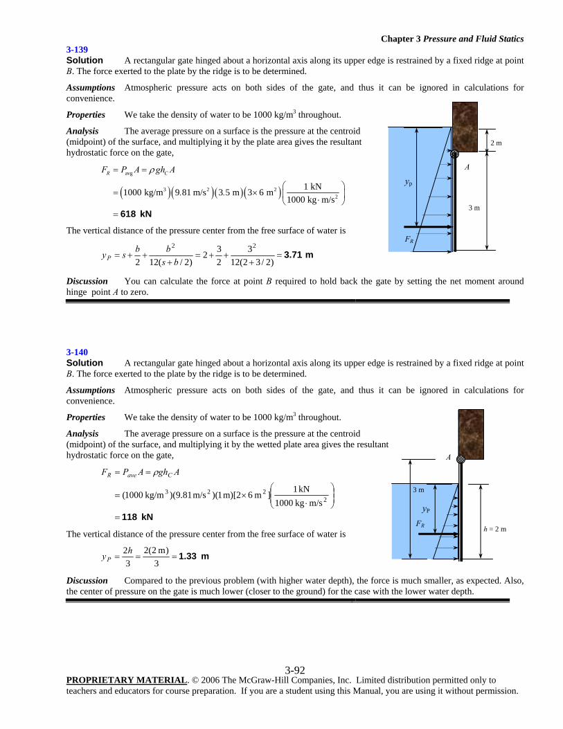
Chapter 3 Pressure and Fluid Statics
PROPRIETARY MATERIAL. © 2006 The McGraw-Hill Companies, Inc. Limited distribution permitted only to teachers and educators for course preparation. If you are a student using this Manual, you are using it without permission.
3-92
3-139 Solution A rectangular gate hinged about a horizontal axis along its upper edge is restrained by a fixed ridge at point B. The force exerted to the plate by the ridge is to be determined.
Assumptions Atmospheric pressure acts on both sides of the gate, and thus it can be ignored in calculations for convenience.
Properties We take the density of water to be 1000 kg/m3 throughout.
Analysis The average pressure on a surface is the pressure at the centroid (midpoint) of the surface, and multiplying it by the plate area gives the resultant hydrostatic force on the gate,
( )( )( )( )avg
3 2 22
1 kN1000 kg/m 9 81 m/s 3 5 m 3 6 m1000 kg m/s
R CF P A gh A
. .
ρ= =
⎛ ⎞= × ⎜ ⎟⋅⎝ ⎠= 618 kN
The vertical distance of the pressure center from the free surface of water is
m 3.71=+
++=+
++=)2/32(12
3232
)2/(122
22
bsbbsyP
Discussion You can calculate the force at point B required to hold back the gate by setting the net moment around hinge point A to zero.
3-140 Solution A rectangular gate hinged about a horizontal axis along its upper edge is restrained by a fixed ridge at point B. The force exerted to the plate by the ridge is to be determined.
Assumptions Atmospheric pressure acts on both sides of the gate, and thus it can be ignored in calculations for convenience.
Properties We take the density of water to be 1000 kg/m3 throughout.
Analysis The average pressure on a surface is the pressure at the centroid (midpoint) of the surface, and multiplying it by the wetted plate area gives the resultant hydrostatic force on the gate,
kN 118=
⎟⎟⎠
⎞⎜⎜⎝
⎛
⋅×=
==
2223
m/s kg1000 kN1]m 6m)[2 1)(m/s 81.9)( kg/m1000(
AghAPF CaveR ρ
The vertical distance of the pressure center from the free surface of water is
m 1.33===3
)m 2(23
2hyP
Discussion Compared to the previous problem (with higher water depth), the force is much smaller, as expected. Also, the center of pressure on the gate is much lower (closer to the ground) for the case with the lower water depth.
FR
3 m
yP
h = 2 m
A
FR
3 m
A
2 m
yp
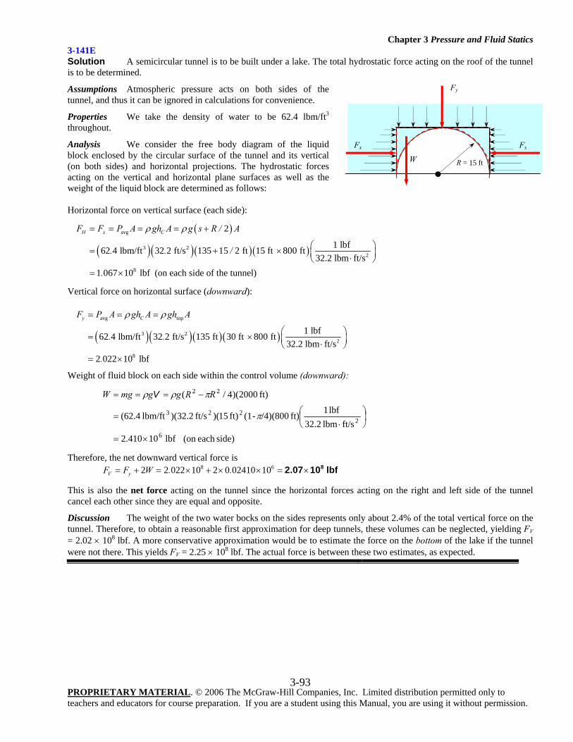
Chapter 3 Pressure and Fluid Statics
PROPRIETARY MATERIAL. © 2006 The McGraw-Hill Companies, Inc. Limited distribution permitted only to teachers and educators for course preparation. If you are a student using this Manual, you are using it without permission.
3-93
3-141E Solution A semicircular tunnel is to be built under a lake. The total hydrostatic force acting on the roof of the tunnel is to be determined.
Assumptions Atmospheric pressure acts on both sides of the tunnel, and thus it can be ignored in calculations for convenience.
Properties We take the density of water to be 62.4 lbm/ft3 throughout.
Analysis We consider the free body diagram of the liquid block enclosed by the circular surface of the tunnel and its vertical (on both sides) and horizontal projections. The hydrostatic forces acting on the vertical and horizontal plane surfaces as well as the weight of the liquid block are determined as follows: Horizontal force on vertical surface (each side):
( )
( )( )( )( )
avg
3 22
8
2
1 lbf62 4 lbm/ft 32 2 ft/s 135 15 2 ft 15 ft 800 ft32.2 lbm ft/s
1 067 10 lbf (on each side of the tunnel)
H x CF F P A gh A g s R / A
. . /
.
ρ ρ= = = = +
⎛ ⎞= + × ⎜ ⎟⋅⎝ ⎠= ×
Vertical force on horizontal surface (downward):
( )( )( )( )
avg top
3 22
8
1 lbf62 4 lbm/ft 32 2 ft/s 135 ft 30 ft 800 ft32.2 lbm ft/s
2 022 10 lbf
y CF P A gh A gh A
. .
.
ρ ρ= = =
⎛ ⎞= × ⎜ ⎟⋅⎝ ⎠= ×
Weight of fluid block on each side within the control volume (downward):
side) each (on lbf 10410.2ft/slbm 32.2
lbf 1ft) /4)(800-(1ft) 15)(ft/s 2.32)(lbm/ft 4.62(
ft) 2000)(4/(
6
2223
22
×=
⎟⎠⎞
⎜⎝⎛
⋅=
−===
π
πρρ RRggmgW V
Therefore, the net downward vertical force is 8 62 2 022 10 2 0 02410 10V yF F W . .= + = × + × × = × 82.07 10 lbf
This is also the net force acting on the tunnel since the horizontal forces acting on the right and left side of the tunnel cancel each other since they are equal and opposite.
Discussion The weight of the two water bocks on the sides represents only about 2.4% of the total vertical force on the tunnel. Therefore, to obtain a reasonable first approximation for deep tunnels, these volumes can be neglected, yielding FV = 2.02 × 10⁸ lbf. A more conservative approximation would be to estimate the force on the bottom of the lake if the tunnel were not there. This yields FV = 2.25 × 10⁸ lbf. The actual force is between these two estimates, as expected.
Fy
R = 15 ft
Fx Fx
W
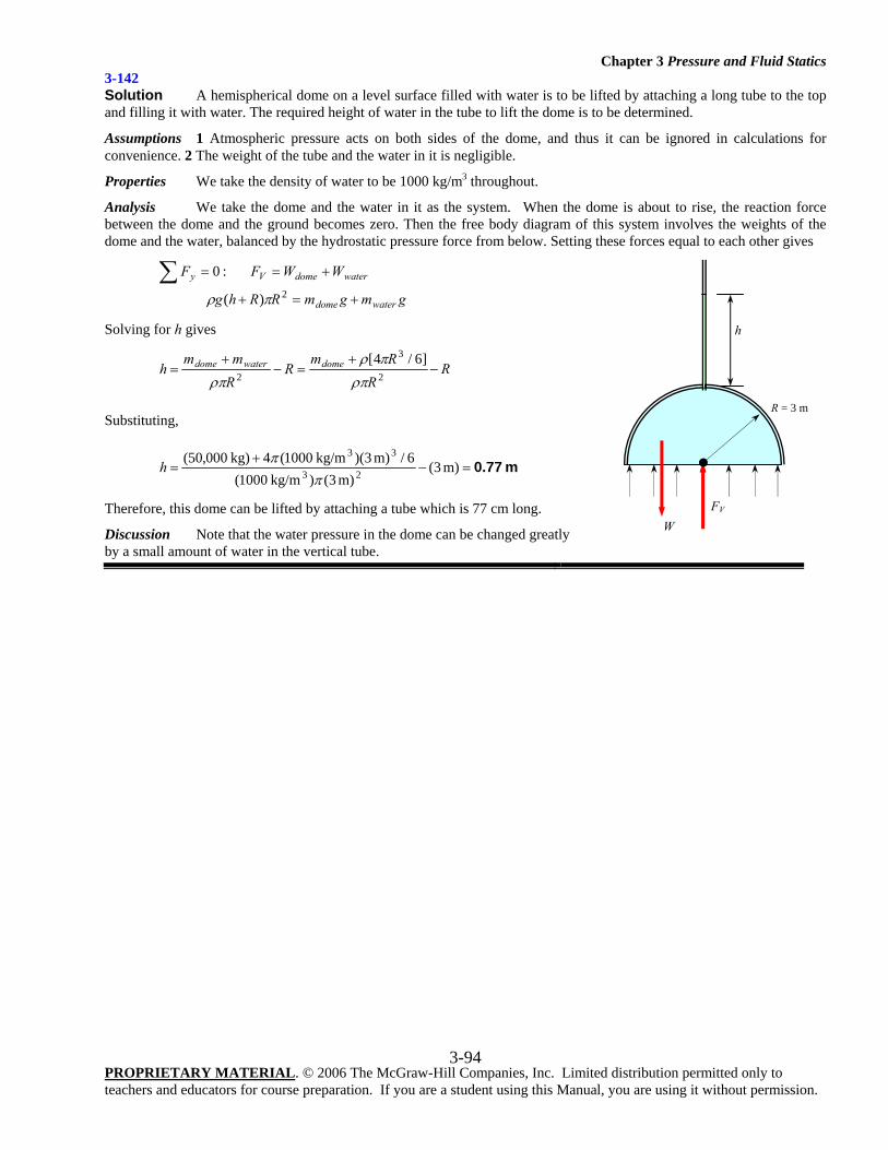
Chapter 3 Pressure and Fluid Statics
PROPRIETARY MATERIAL. © 2006 The McGraw-Hill Companies, Inc. Limited distribution permitted only to teachers and educators for course preparation. If you are a student using this Manual, you are using it without permission.
3-94
3-142 Solution A hemispherical dome on a level surface filled with water is to be lifted by attaching a long tube to the top and filling it with water. The required height of water in the tube to lift the dome is to be determined.
Assumptions 1 Atmospheric pressure acts on both sides of the dome, and thus it can be ignored in calculations for convenience. 2 The weight of the tube and the water in it is negligible.
Properties We take the density of water to be 1000 kg/m3 throughout.
Analysis We take the dome and the water in it as the system. When the dome is about to rise, the reaction force between the dome and the ground becomes zero. Then the free body diagram of this system involves the weights of the dome and the water, balanced by the hydrostatic pressure force from below. Setting these forces equal to each other gives
gmgmRRhg
WWFF
waterdome
waterdomeVy
+=+
+==∑2)(
:0
πρ
Solving for h gives
RR
RmR
Rmm
h domewaterdome −+
=−+
=2
3
2
]6/4[ρπ
πρρπ
Substituting,
m 0.77=−+
= m) 3(m) 3() kg/m1000(
6/m) 3)( kg/m1000(4 kg)000,50(23
33
ππh
Therefore, this dome can be lifted by attaching a tube which is 77 cm long.
Discussion Note that the water pressure in the dome can be changed greatly by a small amount of water in the vertical tube.
FV
R = 3 m
h
W
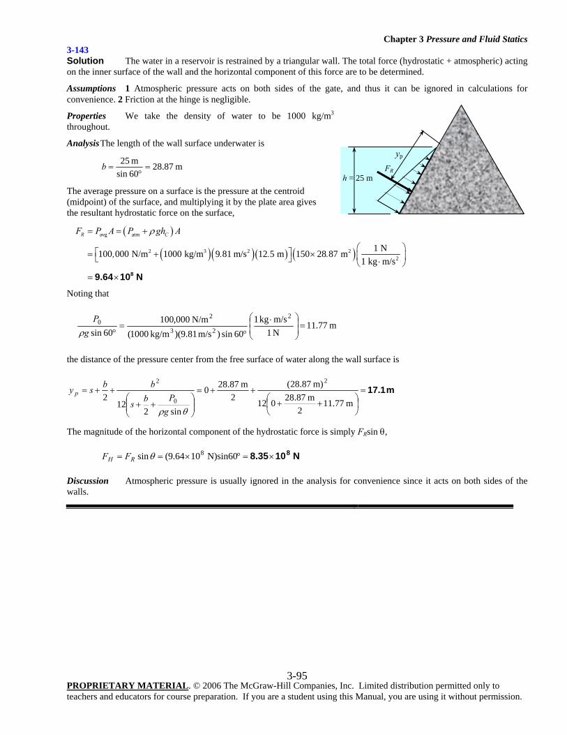
Chapter 3 Pressure and Fluid Statics
PROPRIETARY MATERIAL. © 2006 The McGraw-Hill Companies, Inc. Limited distribution permitted only to teachers and educators for course preparation. If you are a student using this Manual, you are using it without permission.
3-95
3-143 Solution The water in a reservoir is restrained by a triangular wall. The total force (hydrostatic + atmospheric) acting on the inner surface of the wall and the horizontal component of this force are to be determined.
Assumptions 1 Atmospheric pressure acts on both sides of the gate, and thus it can be ignored in calculations for convenience. 2 Friction at the hinge is negligible.
Properties We take the density of water to be 1000 kg/m3 throughout.
Analysis The length of the wall surface underwater is
m 87.2860sinm 25
=°
=b
The average pressure on a surface is the pressure at the centroid (midpoint) of the surface, and multiplying it by the plate area gives the resultant hydrostatic force on the surface,
( )
( )( ) ( ) ( )avg atm
2 3 2 22
1 N100 000 N/m 1000 kg/m 9 81 m/s 12 5 m 150 28 87 m1 kg m/s
R CF P A P gh A
, . . .
ρ= = +
⎛ ⎞⎡ ⎤= + × ⎜ ⎟⎣ ⎦ ⋅⎝ ⎠= × 89.64 10 N
Noting that
m 77.11N 1m/skg 1
60sin)m/s 81.9)(kg/m 1000(N/m 000,100
60sin
2
23
20 =⎟
⎟⎠
⎞⎜⎜⎝
⎛ ⋅
°=
°gP
ρ
the distance of the pressure center from the free surface of water along the wall surface is
m 17.1=⎟⎠⎞
⎜⎝⎛ ++
++=
⎟⎟⎠
⎞⎜⎜⎝
⎛++
++=m 77.11
2m 87.28012
m) 87.28(2
m 87.280
sin212
2
2
0
2
θρgPbs
bbsy p
The magnitude of the horizontal component of the hydrostatic force is simply FRsin θ,
N 108.35 8×=°×== N)sin60 1064.9(sin 8θRH FF
Discussion Atmospheric pressure is usually ignored in the analysis for convenience since it acts on both sides of the walls.
FR h = 25 m
yp
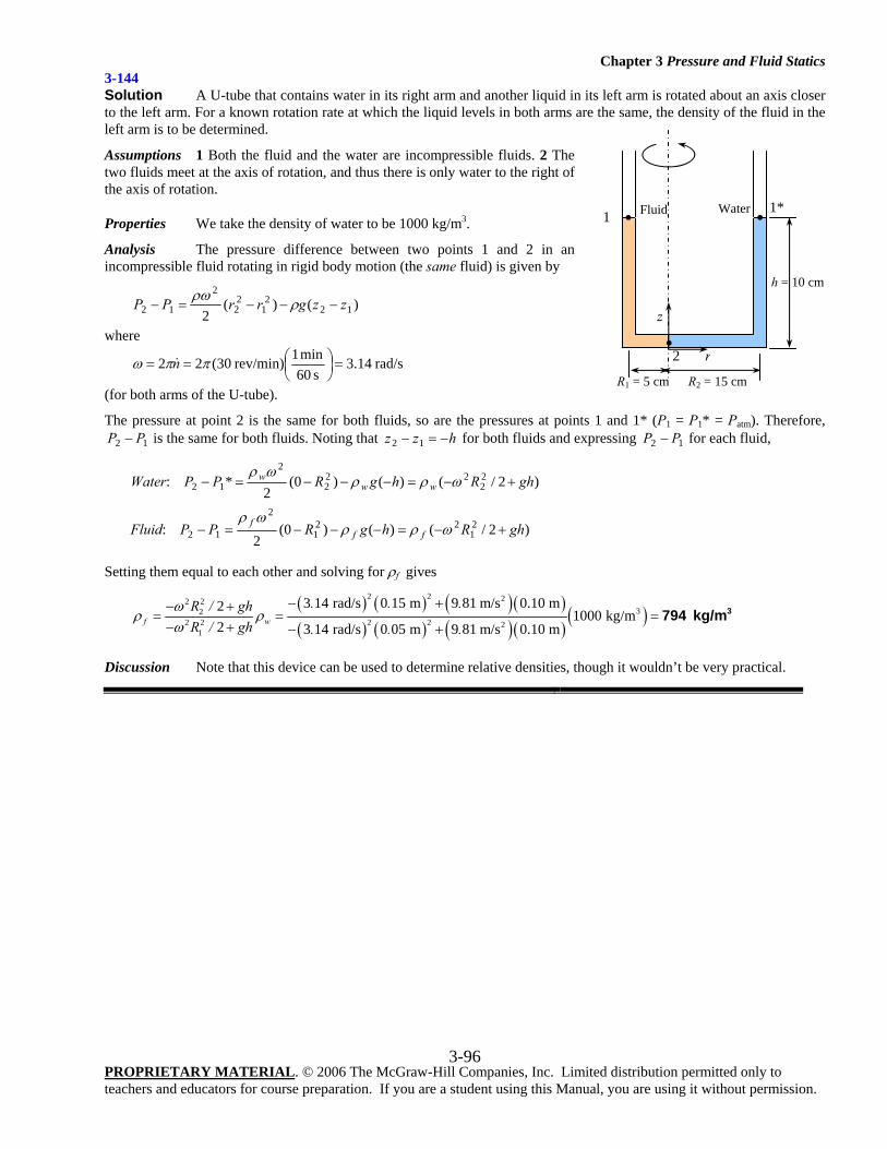
Chapter 3 Pressure and Fluid Statics
PROPRIETARY MATERIAL. © 2006 The McGraw-Hill Companies, Inc. Limited distribution permitted only to teachers and educators for course preparation. If you are a student using this Manual, you are using it without permission.
3-96
3-144 Solution A U-tube that contains water in its right arm and another liquid in its left arm is rotated about an axis closer to the left arm. For a known rotation rate at which the liquid levels in both arms are the same, the density of the fluid in the left arm is to be determined.
Assumptions 1 Both the fluid and the water are incompressible fluids. 2 The two fluids meet at the axis of rotation, and thus there is only water to the right of the axis of rotation.
Properties We take the density of water to be 1000 kg/m3.
Analysis The pressure difference between two points 1 and 2 in an incompressible fluid rotating in rigid body motion (the same fluid) is given by
)()(2 12
21
22
2
12 zzgrrPP −−−=− ρρω
where
rad/s14.3s 60
min 1 rev/min)30(22 =⎟⎠⎞
⎜⎝⎛== ππω n
(for both arms of the U-tube).
The pressure at point 2 is the same for both fluids, so are the pressures at points 1 and 1* (P1 = P1* = Patm). Therefore, 12 PP − is the same for both fluids. Noting that hzz −=− 12 for both fluids and expressing 12 PP − for each fluid,
Water: )2/()()0(2
* 22
222
2
12 ghRhgRPP www +−=−−−=− ωρρωρ
Fluid: )2/()()0(2
21
221
2
12 ghRhgRPP fff +−=−−−=− ωρρωρ
Setting them equal to each other and solving for ρf gives
( ) ( ) ( )( )( ) ( ) ( )( )
( )2 2 22 2
322 2 2 2 2
1
3 14 rad/s 0 15 m 9 81 m/s 0.10 m21000 kg/m
2 3 14 rad/s 0 05 m 9 81 m/s 0.10 mf w
. . .R / ghR / gh . . .
ωρ ρ
ω
− +− += = =
− + − +3794 kg/m
Discussion Note that this device can be used to determine relative densities, though it wouldn’t be very practical.
R2 = 15 cm
h = 10 cm
R1 = 5 cm
z
r
Water Fluid
• 2
1 • •1*
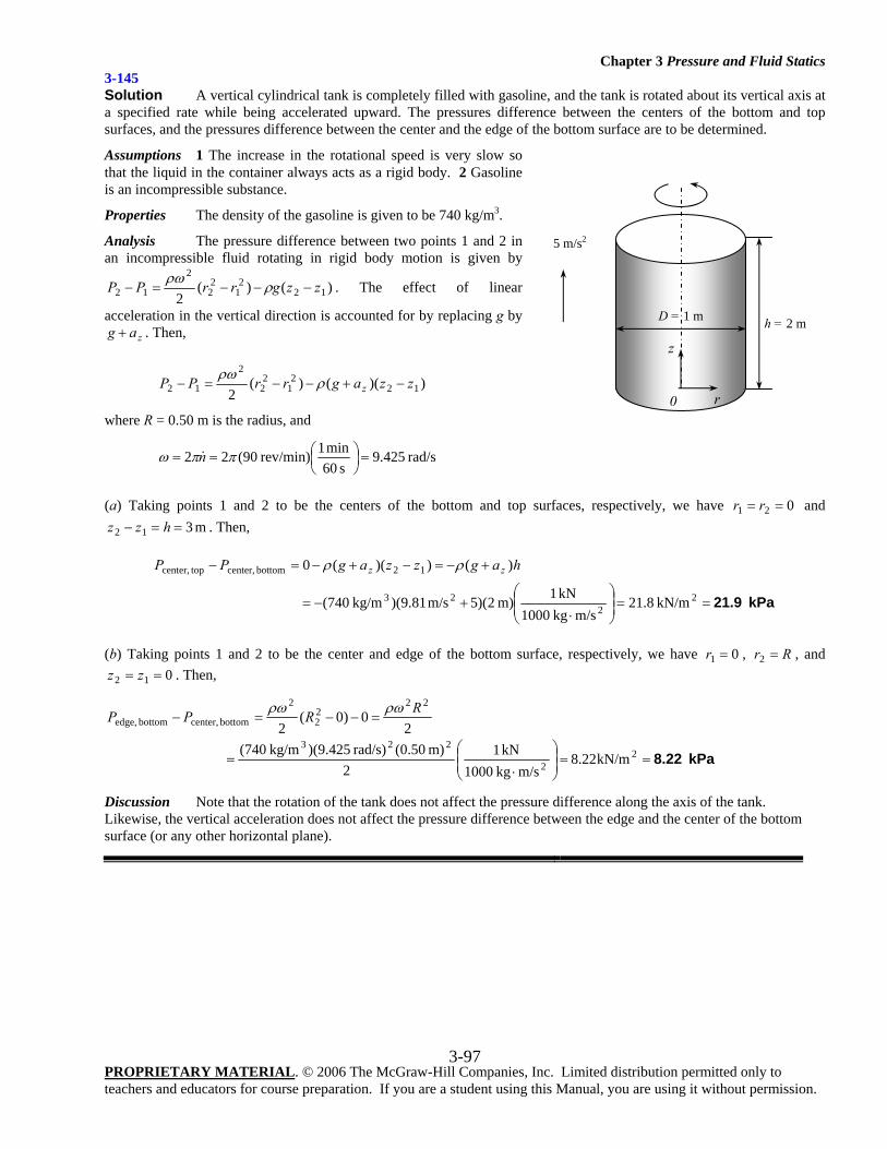
Chapter 3 Pressure and Fluid Statics
PROPRIETARY MATERIAL. © 2006 The McGraw-Hill Companies, Inc. Limited distribution permitted only to teachers and educators for course preparation. If you are a student using this Manual, you are using it without permission.
3-97
3-145 Solution A vertical cylindrical tank is completely filled with gasoline, and the tank is rotated about its vertical axis at a specified rate while being accelerated upward. The pressures difference between the centers of the bottom and top surfaces, and the pressures difference between the center and the edge of the bottom surface are to be determined.
Assumptions 1 The increase in the rotational speed is very slow so that the liquid in the container always acts as a rigid body. 2 Gasoline is an incompressible substance.
Properties The density of the gasoline is given to be 740 kg/m3.
Analysis The pressure difference between two points 1 and 2 in an incompressible fluid rotating in rigid body motion is given by
)()(2 12
21
22
2
12 zzgrrPP −−−=− ρρω . The effect of linear
acceleration in the vertical direction is accounted for by replacing g by zag + . Then,
))(()(2 12
21
22
2
12 zzagrrPP z −+−−=− ρρω
where R = 0.50 m is the radius, and
rad/s425.9s 60
min 1 rev/min)90(22 =⎟⎠⎞
⎜⎝⎛== ππω n
(a) Taking points 1 and 2 to be the centers of the bottom and top surfaces, respectively, we have 021 == rr and m 312 ==− hzz . Then,
kPa 21.9==⎟⎟⎠
⎞⎜⎜⎝
⎛
⋅+−=
+−=−+−=−
22
23
12 bottomcenter, topcenter,
kN/m8.21m/s kg1000
kN1m) 2)(5m/s 81.9)( kg/m740(
)())((0 hagzzagPP zz ρρ
(b) Taking points 1 and 2 to be the center and edge of the bottom surface, respectively, we have 01 =r , Rr =2 , and 012 == zz . Then,
20)0(
2
2222
2
bottomcenter, bottomedge,RRPP ρωρω
=−−=−
kPa 8.22==⎟⎟⎠
⎞⎜⎜⎝
⎛
⋅= 2
2
223kN/m22.8
m/s kg1000 kN1
2m) 50.0( rad/s)425.9)( kg/m740(
Discussion Note that the rotation of the tank does not affect the pressure difference along the axis of the tank. Likewise, the vertical acceleration does not affect the pressure difference between the edge and the center of the bottom surface (or any other horizontal plane).
5 m/s2
h = 2 m D = 1 m
z
r0
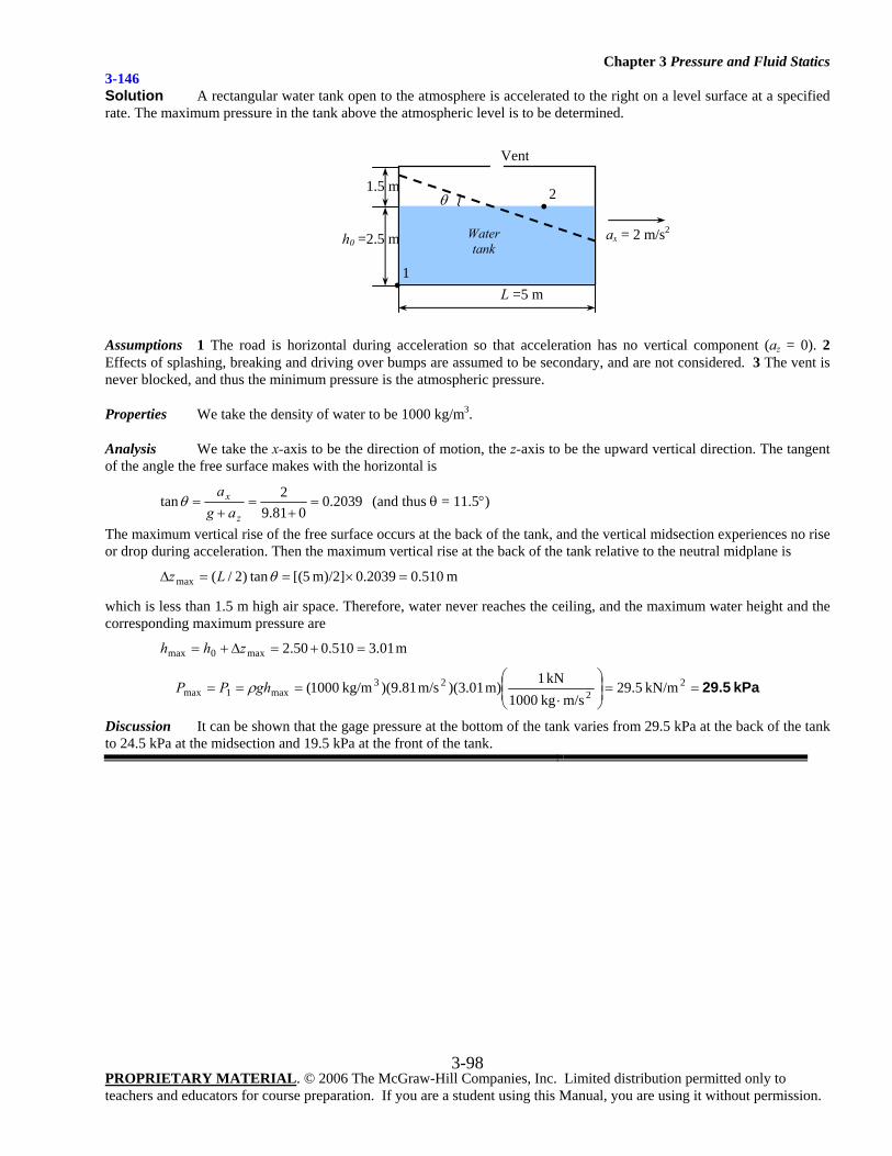
Chapter 3 Pressure and Fluid Statics
PROPRIETARY MATERIAL. © 2006 The McGraw-Hill Companies, Inc. Limited distribution permitted only to teachers and educators for course preparation. If you are a student using this Manual, you are using it without permission.
3-98
3-146 Solution A rectangular water tank open to the atmosphere is accelerated to the right on a level surface at a specified rate. The maximum pressure in the tank above the atmospheric level is to be determined.
Assumptions 1 The road is horizontal during acceleration so that acceleration has no vertical component (az = 0). 2 Effects of splashing, breaking and driving over bumps are assumed to be secondary, and are not considered. 3 The vent is never blocked, and thus the minimum pressure is the atmospheric pressure.
Properties We take the density of water to be 1000 kg/m3.
Analysis We take the x-axis to be the direction of motion, the z-axis to be the upward vertical direction. The tangent of the angle the free surface makes with the horizontal is
2039.0081.9
2tan =+
=+
=z
x
aga
θ (and thus θ = 11.5°)
The maximum vertical rise of the free surface occurs at the back of the tank, and the vertical midsection experiences no rise or drop during acceleration. Then the maximum vertical rise at the back of the tank relative to the neutral midplane is
m 510.00.2039m)/2] 5[(tan)2/(max =×==Δ θLz
which is less than 1.5 m high air space. Therefore, water never reaches the ceiling, and the maximum water height and the corresponding maximum pressure are
m 01.3510.050.2max0max =+=Δ+= zhh
kPa 29.5==⎟⎟⎠
⎞⎜⎜⎝
⎛
⋅=== 2
223
max1max kN/m5.29m/s kg1000
kN1m) 01.3)(m/s 81.9)( kg/m1000(ghPP ρ
Discussion It can be shown that the gage pressure at the bottom of the tank varies from 29.5 kPa at the back of the tank to 24.5 kPa at the midsection and 19.5 kPa at the front of the tank.
L =5 m
ax = 2 m/s2 h0 =2.5 m
1.5 m
Water tank
Vent
θ
•1
•2
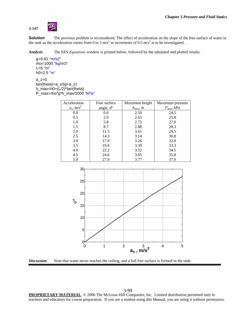
Chapter 3 Pressure and Fluid Statics
PROPRIETARY MATERIAL. © 2006 The McGraw-Hill Companies, Inc. Limited distribution permitted only to teachers and educators for course preparation. If you are a student using this Manual, you are using it without permission.
3-99
3-147
Solution The previous problem is reconsidered. The effect of acceleration on the slope of the free surface of water in the tank as the acceleration varies from 0 to 5 m/s2 in increments of 0.5 m/s2 is to be investigated. Analysis The EES Equations window is printed below, followed by the tabulated and plotted results.
g=9.81 "m/s2" rho=1000 "kg/m3" L=5 "m" h0=2.5 "m"
a_z=0 tan(theta)=a_x/(g+a_z) h_max=h0+(L/2)*tan(theta) P_max=rho*g*h_max/1000 "kPa"
Acceleration
ax, m/s2 Free surface
angle, θ° Maximum height
hmax, m Maximum pressure
Pmax, kPa 0.0 0.5 1.0 1.5 2.0 2.5 3.0 3.5 4.0 4.5 5.0
0.0 2.9 5.8 8.7
11.5 14.3 17.0 19.6 22.2 24.6 27.0
2.50 2.63 2.75 2.88 3.01 3.14 3.26 3.39 3.52 3.65 3.77
24.5 25.8 27.0 28.3 29.5 30.8 32.0 33.3 34.5 35.8 37.0
Discussion Note that water never reaches the ceiling, and a full free surface is formed in the tank.
0 1 2 3 4 50
5
10
15
20
25
30
ax , m/s2
θ°
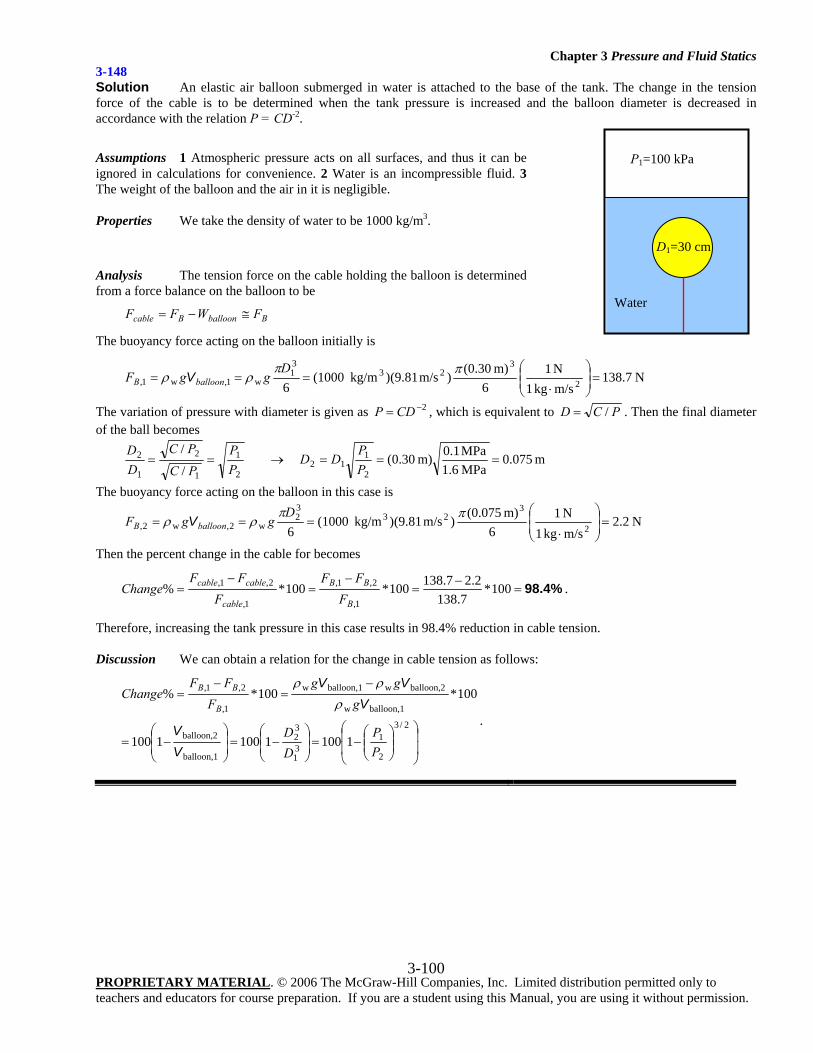
Chapter 3 Pressure and Fluid Statics
PROPRIETARY MATERIAL. © 2006 The McGraw-Hill Companies, Inc. Limited distribution permitted only to teachers and educators for course preparation. If you are a student using this Manual, you are using it without permission.
3-100
3-148 Solution An elastic air balloon submerged in water is attached to the base of the tank. The change in the tension force of the cable is to be determined when the tank pressure is increased and the balloon diameter is decreased in accordance with the relation P = CD-2.
Assumptions 1 Atmospheric pressure acts on all surfaces, and thus it can be ignored in calculations for convenience. 2 Water is an incompressible fluid. 3 The weight of the balloon and the air in it is negligible.
Properties We take the density of water to be 1000 kg/m3.
Analysis The tension force on the cable holding the balloon is determined from a force balance on the balloon to be
BballoonBcable FWFF ≅−=
The buoyancy force acting on the balloon initially is
N 7.138m/s kg1N 1
6m) (0.30
)m/s (9.81) kg/m(10006
2
323
31
w1,w1, =⎟⎟⎠
⎞⎜⎜⎝
⎛
⋅===
ππρρ
DggF balloonB V
The variation of pressure with diameter is given as 2−= CDP , which is equivalent to PCD /= . Then the final diameter of the ball becomes
m 075.0 MPa 6.1MPa 1.0m) 30.0(
/
/
2
112
2
1
1
2
1
2 ===→==PP
DDPP
PC
PCDD
The buoyancy force acting on the balloon in this case is
N 2.2m/skg 1N 1
6m) (0.075
)m/s (9.81)kg/m (10006
2
323
32
w2,w2, =⎟⎟⎠
⎞⎜⎜⎝
⎛
⋅===
ππρρ
DggF balloonB V
Then the percent change in the cable for becomes
98.4%=−
=−
=−
= 100*7.138
2.27.138100*100*%1,
2,1,
1,
2,1,
B
BB
cable
cablecable
FFF
FFF
Change .
Therefore, increasing the tank pressure in this case results in 98.4% reduction in cable tension. Discussion We can obtain a relation for the change in cable tension as follows:
⎟⎟
⎠
⎞
⎜⎜
⎝
⎛⎟⎟⎠
⎞⎜⎜⎝
⎛−=⎟
⎟⎠
⎞⎜⎜⎝
⎛−=⎟
⎟⎠
⎞⎜⎜⎝
⎛−=
−=
−=
2/3
2
131
32
balloon,1
balloon,2
balloon,1w
balloon,2wballoon,1w
1,
2,1,
110011001100
100*100*%
PP
DD
ggg
FFF
ChangeB
BB
VV
VVV
ρρρ
.
Water
P1=100 kPa
D1=30 cm
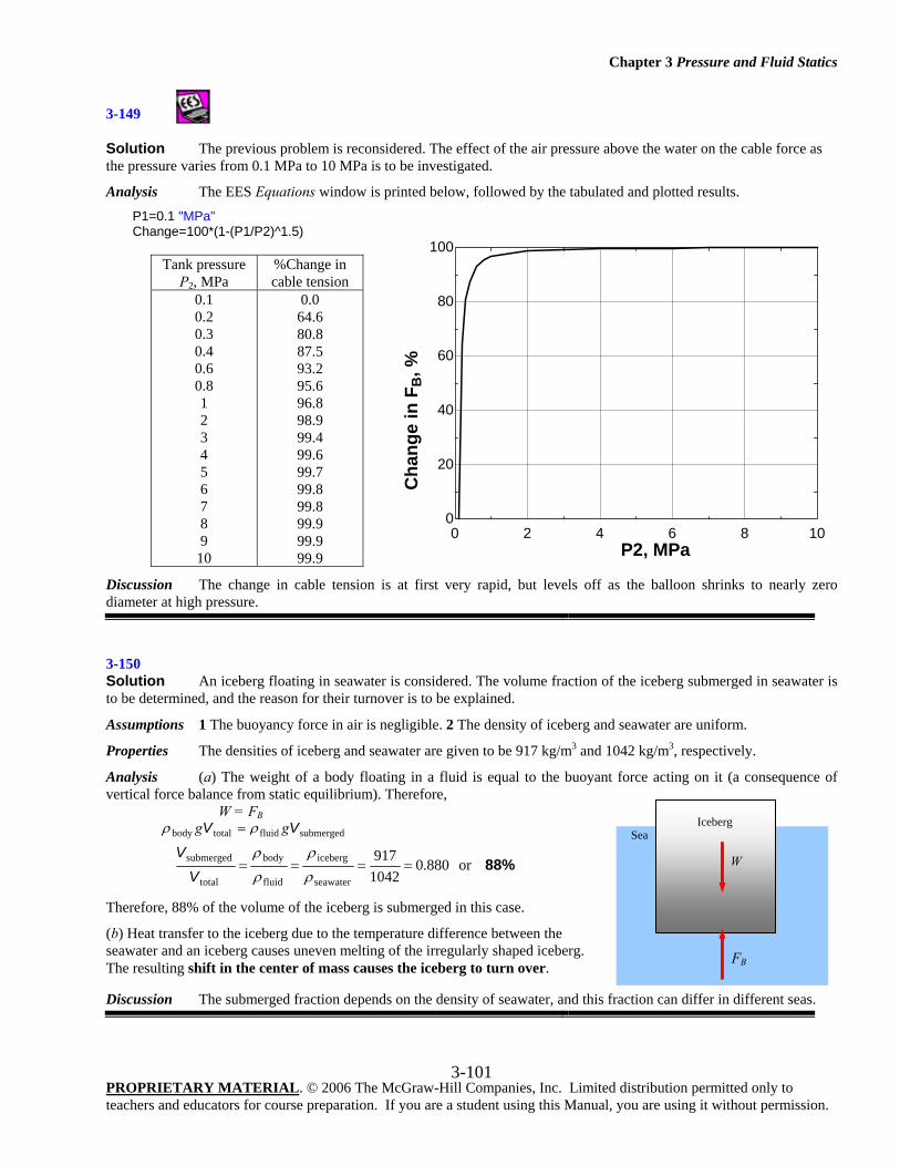
Chapter 3 Pressure and Fluid Statics
PROPRIETARY MATERIAL. © 2006 The McGraw-Hill Companies, Inc. Limited distribution permitted only to teachers and educators for course preparation. If you are a student using this Manual, you are using it without permission.
3-101
3-149
Solution The previous problem is reconsidered. The effect of the air pressure above the water on the cable force as the pressure varies from 0.1 MPa to 10 MPa is to be investigated.
Analysis The EES Equations window is printed below, followed by the tabulated and plotted results.
P1=0.1 "MPa" Change=100*(1-(P1/P2)^1.5)
Tank pressure P2, MPa
%Change in cable tension
0.1 0.2 0.3 0.4 0.6 0.8 1 2 3 4 5 6 7 8 9
10
0.0 64.6 80.8 87.5 93.2 95.6 96.8 98.9 99.4 99.6 99.7 99.8 99.8 99.9 99.9 99.9
Discussion The change in cable tension is at first very rapid, but levels off as the balloon shrinks to nearly zero diameter at high pressure.
3-150 Solution An iceberg floating in seawater is considered. The volume fraction of the iceberg submerged in seawater is to be determined, and the reason for their turnover is to be explained.
Assumptions 1 The buoyancy force in air is negligible. 2 The density of iceberg and seawater are uniform.
Properties The densities of iceberg and seawater are given to be 917 kg/m3 and 1042 kg/m3, respectively.
Analysis (a) The weight of a body floating in a fluid is equal to the buoyant force acting on it (a consequence of vertical force balance from static equilibrium). Therefore,
W = FB
submergedfluidtotalbody VV gg ρρ =
88%or 880.01042917
seawater
iceberg
fluid
body
total
submerged ====ρ
ρ
ρ
ρ
VV
Therefore, 88% of the volume of the iceberg is submerged in this case.
(b) Heat transfer to the iceberg due to the temperature difference between the seawater and an iceberg causes uneven melting of the irregularly shaped iceberg. The resulting shift in the center of mass causes the iceberg to turn over. Discussion The submerged fraction depends on the density of seawater, and this fraction can differ in different seas.
Sea
FB
W
Iceberg
0 2 4 6 8 100
20
40
60
80
100
P2, MPa
Cha
nge
in F
B, %
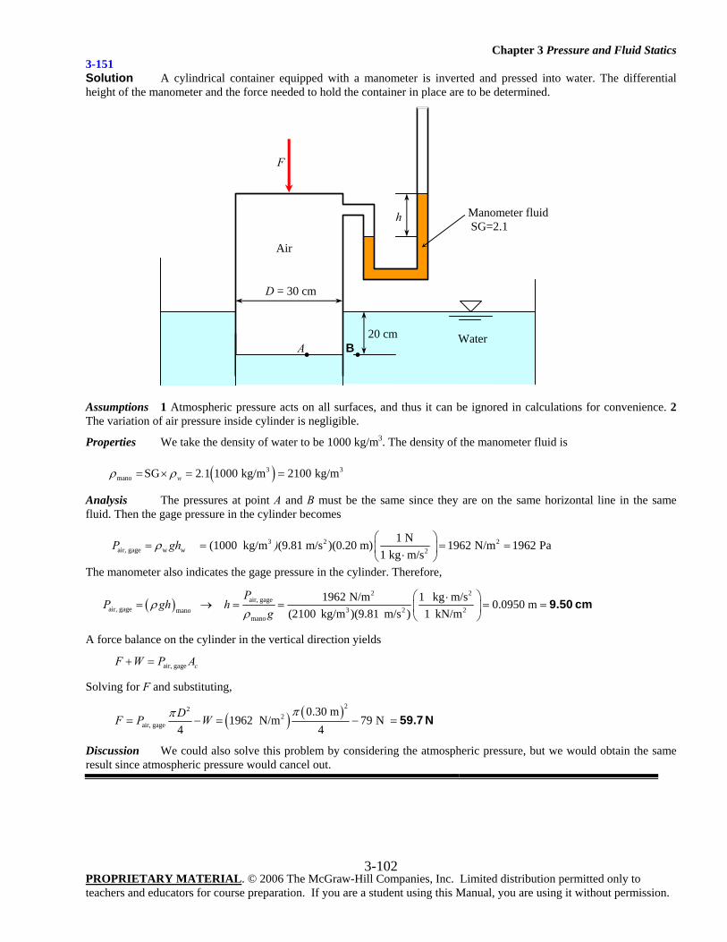
Chapter 3 Pressure and Fluid Statics
PROPRIETARY MATERIAL. © 2006 The McGraw-Hill Companies, Inc. Limited distribution permitted only to teachers and educators for course preparation. If you are a student using this Manual, you are using it without permission.
3-102
3-151 Solution A cylindrical container equipped with a manometer is inverted and pressed into water. The differential height of the manometer and the force needed to hold the container in place are to be determined.
Assumptions 1 Atmospheric pressure acts on all surfaces, and thus it can be ignored in calculations for convenience. 2 The variation of air pressure inside cylinder is negligible.
Properties We take the density of water to be 1000 kg/m3. The density of the manometer fluid is
( )3 3mano SG 2 1 1000 kg/m 2100 kg/mw .ρ ρ= × = =
Analysis The pressures at point A and B must be the same since they are on the same horizontal line in the same fluid. Then the gage pressure in the cylinder becomes
3 2 2air, gage w w 2
1 N (1000 kg/m (9.81 m/s )(0.20 m) 1962 N/m 1962 Pa1 kg m/s
P gh )ρ⎛ ⎞
= = = =⎜ ⎟⋅⎝ ⎠
The manometer also indicates the gage pressure in the cylinder. Therefore,
( )2 2
air, gageair, gage 3 2 2mano
mano
1962 N/m 1 kg m/s 0.0950 m(2100 kg/m )(9.81 m/s ) 1 kN/m
PP gh h
gρ
ρ⎛ ⎞⋅
= → = = = =⎜ ⎟⎝ ⎠
9.50 cm
A force balance on the cylinder in the vertical direction yields
air, gage cF W P A+ =
Solving for F and substituting,
( ) ( )222
air, gage
0.30 m1962 N/m 79 N
4 4DF P W
ππ= − = − = 59.7 N
Discussion We could also solve this problem by considering the atmospheric pressure, but we would obtain the same result since atmospheric pressure would cancel out.
Air
h Manometer fluid SG=2.1
20 cm
D = 30 cm
F
Water A B • •
Chapter 3 Pressure and Fluid Statics
PROPRIETARY MATERIAL. © 2006 The McGraw-Hill Companies, Inc. Limited distribution permitted only to teachers and educators for course preparation. If you are a student using this Manual, you are using it without permission.
3-103
Design and Essay Problems 3-152 Solution We are to discuss the design of shoes that enable people to walk on water.
Discussion Students’ discussions should be unique and will differ from each other.
3-153 Solution We are to discuss how to measure the volume of a rock without using any volume measurement devices.
Analysis The volume of a rock can be determined without using any volume measurement devices as follows: We weigh the rock in the air and then in the water. The difference between the two weights is due to the buoyancy force, which is equal to yB gF bodwater Vρ= . Solving this relation for Vbody gives the volume of the rock.
Discussion Since this is an open-ended design problem, students may come up with different, but equally valid techniques.