Embed Size (px)
Citation preview

SCHOOL OF ARCHITECTURE, BUILDING & DESIGN BUILDING SERVICES (ARC 2423)
Project 1 Case Study and Documentation of Building Services Systems
Kiew Wee Kee 0310202 Yiew Qunhe 0314809 Ng You Sheng 0309997 Kong Chee Seng 0308360 Gan Chin Bong 0313738

Table of Content 1. INTRODUCTION 3
1.1 General Facilities Information 1.2 Acknowledgement
2. FIRE PROTECTION 6
2.1 Literature Review 2.1.1 Active Fire Protection 2.1.2 Passive Fire Protection
2.2 Active Fire Protection 2.2.1 Detection
2.2.1.1 Smoke Detector 2.2.2 Notification
2.2.2.1 Central Fire Alarm System 2.2.2.2 Fireman Intercom System 2.2.2.3 Fire Control Room
2.2.3 Action 2.2.3.1 Water Based- System
2.2.3.1.1 Fire Sprinkler System 2.2.3.1.2 Fire Hose Reel System 2.2.3.1.3 Fire Pump Room 2.2.3.1.4 Dry Riser System 2.2.3.1.5 External Fire Hydrant System
2.2.3.2 Non- Water Based System 2.2.3.2.1 Carbon Dioxide (CO2) Fire Suppression System 2.2.3.2.2 Portable Fire Extinguishers
2.3 Passive Fire Protection 2.3.1 Site & Space Planning 2.3.2 Materials 2.2.3 Escape routes 2.3.4 Assembly point
3. AIR CONDITIONING AND MECHANICAL VENTILATION SYSTEM 68
3.1 Literature Review 3.2 Schematic Diagram of Operation System 3.3 Cooling Tower
3.3.1 Condensed Water Pump (CWP) 3.3.2 Water Tank
3.4 Chiller Plant 3.4.1 Component of Chiller Plant
3.5 HVAC (Heating, Ventilation and Air Conditioning) System 3.5.1 Air Handling System 3.5.2 Fan Coil System (FCU)
3.5.2.1 Fan Coil Unit Design Strategy 3.6 Pressurization and Exhaust System
1

4. ELECTRICAL SUPPLY SYSTEM 89
4.1 Literature Review 4.2 The electricity supply system in Sunway Medical Centre 4.3 High Voltage Room: TNB Substation 4.4 High Voltage Room: Consumer Room
4.4.1 High Tension Switch Gear 4.4.2 TNB Meters 4.4.3 Rubber Mats Flooring
4.5 Transformer Room 4.5.1 Transformer 4.5.2 Oil-Insulated Transformer 4.5.3 Dry Type Transformer
4.6 Main Switchboard Room 4.6.1 Main Switchboard 4.6.2 Low Voltage Distribution 4.6.3 Distribution Board 4.6.4 Circuit Breaker
4.7 Electrical Supply Backup System 4.7.1 Genset Room 4.7.2 UPS Room - Uninterruptible Power System
4.8 Sunway Medical Centre Electric Supply System Analysis
5. MECHANICAL TRANSPORTATION 107 5.1 Introduction
5.2 Literature Review 5.3 Elevator System
5.3.1 Drawings 5.3.2 Elevator Components 5.3.3 Geared Machine 5.3.4 Control System 5.3.5 Control Room 5.3.6 Fire Lift
5.4 Service System 5.4.1 Dumbwaiter System 5.4.2 Pneumatic tube System 5.5 Analysis 5.6 Design Consideration
6. CONCLUSION 129 7. REFERENCE 130
2

1. INTRODUCTION
(Source: http://www.sunwayproperty.com/pd/images/ilSouthQuay/g3.jpg)
Sunway Medical Centre is one of Malaysia’s leading private hospitals strategically located within Sunway Resort City, an integrated township situated in the district of Klang Valley with residential, commercial, hospitality, healthcare and educational and entertainment components. Sunway Medical Centre provides a wide range of medical and surgical services of international standard for total management of patients including outpatient and in-patient speciality care, health and wellness services and 24-hour emergency services. Key specialties include cardiology, cochlear implants, haematology, neurology and paediatrics, among others. The complex has over 150 medical and surgical consultants offering a high standard of specialist and general treatment.
Sunway Medical Centre is the recipient of numerous accreditations such as:
MS ISO 15189: 2007 by Standards Malaysia
Sunway Medical Centre made national history in 2005 by being the first Hospital (Laboratory) in Malaysia to be accredited with MS ISO 15189:2004 ‘Medical laboratories. In November 2008, the Laboratory was confirmed to be in compliance with the new version of MS ISO 15189:2007 and was issued the new Certificate of Accreditation bearing Laboratory Accreditation Scheme of Malaysia (SAMM) No: 306.The Certificate of Accreditation is valid until 11 October 2014.
"AIS" Quality Management Excellence Award Sunway Medical Centre has been awarded the prestigious Quality Management Excellence Award. ‘Anugerah Industri Selangor’ (AIS) Quality Management Excellence Award are organised by the Selangor State Investment Centre (SSIC) Berhad. The objective of AIS is to recognise high-performing achievers from different industries in Selangor. AIS is also an added incentive given by the Government to effectively spur these outstanding industries to upgrade their quality and services.
Source: Sunway Medical Centre
Source: Sunway Medical Centre
3

1.1 General Facilities Information
Property description A 7-storey hospital and multi-storey car park (675 car parking lots)
Facilities 12 operating theatres, 94 consultation suites and convention centre (500 guests capacity and audio-video linkages for live telecasts of surgical procedures)
Hospital beds 305 beds (licensed for, and expandable to, 342 beds)
Land title Leasehold interest for a term of 99 years, expiring on 1st April 2097
Building age Phase 1 (hospital tower) – 11 years Phase 2 (east wing, west wing, convention tower, multi-storey car park) – 3 years
Land area 18,194 sq. m. total Gross floor area 70,822 sq. m. (including car park), 50,647 sq. m
(excluding car park) Hospital master lease Master lease for an initial period of 10 years
with an option to renew at prevailing market rate for another 10 years. Rental rate increase of 3.5% per annum for the remaining 9 years of the initial period.
Commencement rent RM 19 million for the first year (implied capitalization rate of 6.13%)
Purchase consideration RM 310 million Independent valuation RM 310 million (as at 3 October 2012)
4

1.2 Acknowledgement
We would like to express our deepest appreciation to all those who provided us the possibility to complete this report. A special gratitude we give to the manager and assistant manager of building service department, Mr. Wong Choon Yuew and Mr. Mohd Kamal B. Mamat who provide good hospitality during our visit and given us his precious time. Besides he has been very kind by providing us as much information as he can, bringing us around the building and providing explanation and answer to our curiosity. Furthermore, we want to thank the authority of Sunway Medical Centre for giving us permission to do a study about the systems that runs this building. On top of that we would like to thank our tutor, Mr Siva for providing us guidance to complete this report. We appreciate much for all the suggestions sir has given to us during tutorial session. Never the less, we would like to thank each member that has put in effort in cooperating with each other’s to make this project happen, especially those who had provided transportation to our site and also those who had help other members who are weaker. By all mean, we would like to once again express our gratitude to everyone who had help making this project a success. Thank you.
5

2. FIRE PROTECTION 2.1 Literature Review
Fire is the result of the combination of 3 important elements:
It is important to know that fire will occur only if all the 3 elements are present at the same time. Fire is an important process that affects ecological systems around the globe.
The purpose of installing fire protection systems in a building, no matter it is active or passive:
1. To protect building occupants from fire by providing sufficient and safe evacuation routes.
2. To protect building structures from severely damage within specific time- construction methods, fire rated, etc.
3. To protect building properties (furniture, equipment, etc.) from totally damage. To avoid fire from spreading out within the building or to another building.
A building design is considered good if the fire safety measures provided in the building are sufficient and adequate for the occupants.
Fire protection system in a building can be subdivided into 2 types:
1. Active Fire Protection System 2. Passive Fire Protection System
FUEL
OXYGEN HEAT
The positive effects of fire:
1. Stimulating growth 2. Maintaining various ecological systems
Negative effects of fire:
1. Hazard to life and property 2. Atmospheric pollution 3. Water contamination
6

2.1.1 Active Fire Protection
Active fire protection (AFP) is a system which is activated either mechanically or electronically during a fire outbreak in a building. It is basically the manual or automatic fire fighting system being installed in a building, such as: fire alarms, detectors, rising mains, hose reels, sprinklers, etc. that functions to give a warning on an outbreak of a fire.
The function of an active fire protection system is to:
To detect the early stage of fire To give fire emergency warning To help occupants evacuate To give early stage of help
2.1.2 Passive Fire Protection
By law, every building needs to have passive fire protection. It is to provide safety for the users during an evacuation of fire. An effective passive fire protection can be done on a building by considering the users of the building, the function of the building, the height of the building and the type of the building. Users should be protected within the building during the evacuation. Generally, the idea to escape the building is to provide escape route, emergency access, uses of materials that have high fire resistant and not depending on the operation of mechanical device.
A safe escape route is needed to provide safe surroundings for user to be able to leave the building and gather at the assembly point safely, hence escape route need to be kept clear from obstructions, so that there is a clear path for user, in order to keep it clear, some areas are suggested to be emergency access. Besides, most of the time the escape routes are normally located at areas which are less likely to be the starting point of fire. Some routes are also being close/block in order to redirect users to the escape routes. Some building include smoke chamber before entering the escape routes, normally windows are placed in this chamber to filter out the smoke but some do it mechanically. Escape routes are also well ventilated with windows or mechanically, this is to ensure sufficiency of oxygen within the routes. Never the less, the materials that are used need to be fire resistance materials, it is buy time for the users to leave the building, to prevent the spreading of the fire towards the escape routes.
7

8
2.2 Active Fire ProtectionThe active fire protection system in Sunway Medical Centre can be thoroughlyexplained through the fire protection chart flow:
Figure: Fire Protection Chart Flow (Sunway Medical Centre)
The fire protection/ fire- fighting system in a building always go through a few stages,which is the detection stage, notification stage and action- taking stage.
When there’s a fire in a building, we need early detection of it in order to preventfurther damage to both people and building. In Sunway Medical Centre, detectorsare powered & connected by a central fire alarm system where it is triggered oncefire is detected (Automatic). Detection of fire also further triggers the automatic firesuppression system to put off the fire.
FIRE OUT-BREAK
DETECTION SMOKE DETECTOR
NOTIFICATION CENTRAL FIRE ALARM SYSTEM
FIREMAN INTERCOM SYSTEM
FIRE CONTROL ROOM
FIRE EMERGENCY LIGHT
FIRE ALARM BELL
MANUAL CALL POINT
ACTION (FIRE FIGHTING)
WATER- BASED SYSTEM
FIRE SPRINKLER SYSTEM
FIRE HOSE REEL SYSTEM
FIRE PUMP ROOM
DRY RISER SYSTEM
EXTERNAL FIRE HYDRANT SYSTEM
NON- WATER BASED SYSTEMCO2 FIRE SUPPRESSION SYSTEM
PORTABLE FIRE EXTINGUISHERS

9
2.2.1.1 Smoke DetectorA smoke detector is a device that senses smoke, typically as an indicator of fire. Itacts as a important safety tool to detect smoke and fire in the building. Usually thesmoke detector is directly connected or powered by a central fire alarm system; sothat the moment fire is sensed through the detector, notification can be passed outto inform everyone in the building.
Smoke detectors can be divided into 2 types:1. Photoelectric Smoke Detectors2. Ionization Smoke Detectors
Sunway Medical Centre is equipped with ionization smoke detectors.
Figure: Ionization Smoke Detectors in Sunway Medical Centre
Ionization Smoke Detectors
According to Marshall Brain (n.d.), ionization smoke detectors uses an ionizationchamber and a source of ionizing radiation to detect smoke.
Figure: Typical ionization smoke detectors (parts & components)Source:http://home.howstuffworks.com/home-improvement/household-safety/fire/smoke4.htm
Ionization smoke detectors consist of:
1. Printed circuit board2. Ionization chamber3. Electric horn

10
Ionization smoke detectors are common because:1. Inexpensive2. Better at detecting the smaller amounts of smoke produced by flaming fires.
Figure: Typical Ionization ChamberSource: http://www.epa.gov/radiation/sources/smoke_ion.html
The ionization chamber is an aluminium can containing the ionization source. Thecan itself act as the negative plate of the ionization chamber. The chamber is verysimple. It consists of two plates with a voltage across them, along with a radioactivesource of ionizing radiation.
Analysis
Under UBBL 1984 Section 153: Smoke Detectors for Lift Lobbies
1. All lift lobbies shall be provided with smoke detectors.
2. Lift not opening into a smoke lobby shall not use door reopening devicescontrolled by light beam or photo- detectors unless incorporated with a forceclose feature which after thirty seconds of any interruption of the beam causesthe door to close within a preset time.

11
Figure: Smoke Detectors located on 2nd floor of Sunway Medical Centre
From the plan above, it is shown that the ionization smoke detectors are locatedmostly at the lift lobbies and along the corridor. Thus, Sunway Medical Centre fulfillsthe requirement stated in UBBL about the location of smoke detectors in a building.
According to Mr. Karmal, there are a total of 100 units of smoke detectors in Tower A;as for Tower B, it is estimated to be more than 100 units.

12
2.2.2.1 Central Fire Alarm System
It is essential for large buildings to be equipped with a fire alarm system.
Fire alarm system is a set of electric or electronic devices working together to detectand alert people through visual and audio appliances when smoke or fire is present.The system is normally connected with smoke detectors, heat detectors, etc. whichwill automatically trigger the fire alarm system once fire is detected.
There are 2 types of fire alarm system:1. Standard Conventional Fire Alarm System2. Analogue Addressable Fire Alarm System
According to Argus Fire Protection (2011),
Conventional Fire Alarm System Addressable Fire Alarm System
- Simple switches, either ‘on’ or ‘off’
- Cannot distinguish between real fire orvarious non- fire phenomena (e.g.Tobacco smoke, dust & steam)
- Only able to indicate zone
- Effective for small buildings
- Constant 2 way communicationbetween control panel & detectors
- Greater sensitivity to fire with greaterimmunity to false alarms
- Control panel able to identify
- Effective for large buildings
In Sunway Medical Centre, addressable fire alarm system is used instead of theconventional system.
Figure 2.2.2.1.1: Readings showing the exact location of the fire break out can be printed out

13
The master control panel in the fire control room in Sunway medical Centre is able toidentify each device individually in he case of a fire break out and also to print outthe readings showing the exact location of the device which is triggered.
Figure 2.2.2.1.2: Typical Schematic Diagram showing how a fire alarm system worksSource: http://hhtsweblog.typepad.com/photos/fire_alarm_systems/systemdiagramsnf.html
Figure 2.2.2.1.3: Control panel box, alarm bell &emergency break glass located near to theconsumer room in Sunway Medical Centre
The fire alarm system in Sunway Medical Centre is installed with 3 types of alarmmechanism in order to notify people in the building during a fire break out that theremight be a need for evacuation from the building.

14
The 3 mechanisms are:
1. Fire Emergency Light
Figure 2.2.2.1.4: Fire Emergency Light located in Transformer room
The emergency lighting is lighting for an emergency situation when the main powersupply is cut and any normal illumination fails. Required to operate fullyautomatically, the fire emergency light needs to give illumination of a sufficient highlevel to ensure all occupants can evacuate safely during a fire break out. Theemergency light is normally installed in corridors where people need to have a clearview when evacuating.
According to Mr. Karmal, there are a total of 100 over emergency light installed inboth tower A & B of Sunway Medical Centre.
Main corridor - 5 unitsEach room - 1 unit
2. Fire Alarm Bell
Figure 2.2.2.1.5: Fire Alarm Bell located along the corridor in lower ground floor
The fire alarm bell can be operated in 2 ways, either from the fire control room or bybreaking down the glass of the manual call point. The fire alarm bell is of high pitch

15
in order to alert the occupants in the building that there is a fire break out andevacuation is needed.
3. Manual Call Point
Figure 2.2.2.1.6: Manual Call Point
A manual call point is an emergency break class installed in a building for theoccupants to manually activate it when fire occurs. It is designed to be operatedeither by button pushing or handle pulling, depending on the brand of manual callpoint installed.
In Sunway Medical Centre, it is installed with the one with a pull handle.
In Sunway Medical Centre, Addressable Manual Call Point is installed in every floor inorder to identify the exact location of the fire break out. Once the call point is brokeand activated, a signal shall be transmitted to the fire control room and the wardenshall be able to receive the address of which call point have been activated.
According to Mr. Karmal, there are a total of 100 over emergency break glassinstalled in Sunway Medical Centre:
Tower A- 29 units/ Tower B- 81 units
Manual Call Point can be subdivided into 2 types:1. Conventional Manual Call Point2. Addressable Manual Call Point

16
Analysis
Under UBBL Section 237: Fire Alarms
1. Fire alarms shall be provided in accordance with the Tenth- Schedule to theseBy- Laws.
2. All premises or buildings with gross floor area excluding carpark and storageareas exceeding 9290 square meters or exceeding 30.5 meters in height shall beprovided with a two- stage alarm system with evacuation (continuos signal) to begiven immediately in the affected section of the premises while an alert(intermittent signal) be given in adjoining section.
3. Provision shall be made for the general evacuation of the premises by action of amaster control.
Under UBBL Section 155 (1): Fire Mode of Operation
The fire mode of operation shall be initiated by a signal from the fire alarm panelwhich may be activated automatically by one of the alarm devices in the building ormanually.
Analysis
Under UBBL 1984 Section 241: Special Requirements for Fire Alarm Systems
In places where there are deaf persons and where places by nature of the occupancyaudible alarm system is undesirable, visible indicator alarm signals shall beincorporated in addition to the normal alarm system.
Figure 2.2.2.1.7: Emergency Fire Stroke Light located at corridors of Sunway Medical Centre

17
There is another special type of mechanism installed in Sunway Medical Centre,which is the Emergency Fire Stroke Light. This mechanism is installed effectively forthe usage of deaf and poor hearing occupants in the building that might not be ableto hear the emergency fire alarm bell. It will produce strokes of red light onceactivated in order to alert the occupants.
Hence, Sunway Medical Centre fulfills and meets with the requirement stated in theUBBL.

18
2.2.2.2 Fireman Intercom SystemThe Fireman Intercom System provides a reliable communication between theMaster Console (Fire Command Centre) and the remote Handset Stations.
The system consists of:
1. Remote handset station
Figure 2.2.2.2.1: Remote Handset Station located at staircase of Sunway Medical Centre
2. Master control panel
Figure 2.2.2.2.2: Master Control panel located at fire control room in Sunway Medical Centre

19
During a fire break out, a call alert lamp will flash with audible signal at the Mastercontrol panel when there is incoming call. As the handset is lifted to answer theincoming call, the audible signal will be silenced. The master control panel is alsoequipped with a fault indicator unit to indicate the type of fault.
Figure 2.2.2.2.3: Digital Alarm Communicator located in Fire Control Room in SunwayMedical Centre
Figure 2.2.2.2.4: Parts & Components of Digital Alarm Communicator
A automatic digital alarm communicator is provided in the fire control room. Thecommunicator is linked directly to Jabatan Bomba; hence if a fire break out occurs inthe building, the system will automatically contact the fireman without humanmanipulating manually.
20
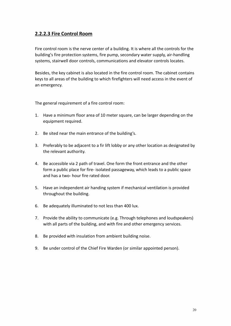
2.2.2.3 Fire Control Room
Fire control room is the nerve center of a building. It is where all the controls for thebuilding's fire protection systems, fire pump, secondary water supply, air-handlingsystems, stairwell door controls, communications and elevator controls locates.
Besides, the key cabinet is also located in the fire control room. The cabinet containskeys to all areas of the building to which firefighters will need access in the event ofan emergency.
The general requirement of a fire control room:
1. Have a minimum floor area of 10 meter square, can be larger depending on theequipment required.
2. Be sited near the main entrance of the building’s.
3. Preferably to be adjacent to a fir lift lobby or any other location as designated bythe relevant authority.
4. Be accessible via 2 path of travel. One form the front entrance and the otherform a public place for fire- isolated passageway, which leads to a public spaceand has a two- hour fire rated door.
5. Have an independent air handing system if mechanical ventilation is providedthroughout the building.
6. Be adequately illuminated to not less than 400 lux.
7. Provide the ability to communicate (e.g. Through telephones and loudspeakers)with all parts of the building, and with fire and other emergency services.
8. Be provided with insulation from ambient building noise.
9. Be under control of the Chief Fire Warden (or similar appointed person).

21
Analysis
Under UBB: 1984 Section 238: Command & Control Centre
Every large premises or building exceeding 30.5 meters in height shall be providedwith a command and control centre located on the designated floor and shall containa panel to monitor the public access, fire brigade communication, sprinkler, waterflow detectors, fire detection and alarm systems and with a direct telephoneconnection to the appropriate fire station by- passing the switchboard.
Figure 2.2.2.3.1: Location of fire control room in Sunway Medical Centre
Although Sunway Medical Centre does not reaches 30.5 meters in height; still, a firecontrol room is provided to maintain the building meets the condition of UBBL.The fire control room is merged together with the security room, which is located onground floor, near to the main lobby, lift & staircase.

22
Figure 2.2.2.3.2: Security roommerged together with the fire control room in SunwayMedical Centre
Figure 2.2.2.3.3: The fire control room of Sunway Medical Centre is fully equipped withspecific facilities used during a fire breakout.
A fire control room must contain the following facilities:
1. Automatic fire alarm and sprinkler indicator boards with facilities for soundingand switching off alarms and visual status indication for all relevant fire pumps,smoke control fans, air- handling systems, generators and other required firesafety equipment installed in each building depending on the circumstances andthe system present in each building.
Figure 2.2.2.3.4: Indicator board showing location of fire breakout

23
2. A telephone connected directly to the external exchange.
Figure 2.2.2.3.5: Telephone used for communication purposes
3. The control console of the Emergency Warning and Intercommunication System(EWIS).
4. A blackboard or whiteboard not less than 1200mm.
5. A pin board not less than 1200mm wide X 1000mm high.
6. A raked plan layout table of a size suitable for laying out the building plan.
7. A repeater panel of the lifts position indicator board.
Figure 2.2.2.3.6: Repeater panel in fire control room
8. A switch to isolate background music when required.
9. Remote switching controls for gas or electrical supplies.

24
10. Building security, surveillance and management systems if they are completelysegregated from all the other systems.
Figure 2.2.2.3.7: Argonite Fire Suppression System
Argonite Fire Suppression System is installed in the fire control room. Normal waterbased suppression system is not suitable to be installed in the room because thereare many electrical appliances which is important since it functions to control andmanipulate the fire fighting system of the whole Sunway Medical Centre.
Argonite Fire Suppression System functions exactly the same as Carbon Dioxide (CO2)Fire Suppression System, where both release gases to displace oxygen, henceextinguishing the fire without damaging the electrical appliances in the fire controlroom.
Besides from fire control room, Argonite Fire Suppression System is also installed inthe following locations in Sunway Medical Centre:
1. X- Ray Room2. Server Room

25
2.2.3.1 Water Based System
2.2.3.1.1 Fire Sprinkler System
Automatic sprinkler system:
The system is intended to detect, control and extinguish a fire automatically withouthuman intervention.
Analysis
Under UBBL 1984 Section 226: Automatic System for Hazardous Occupancy
Where hazardous processes, storage or occupancy are of such character as to requireautomatic system sprinklers or other such character as to require automatic systemsprinklers or other automatic extinguishing system, it shall be of a type and standardappropriate to extinguish fire in the hazardous materials stored or handled or for thesafety of the occupants.
Figure 2.2.3.1.1.1: Automatic Fire Sprinkler System ComponentsSource: http://3.imimg.com/data3/RX/SD/MY-6428964/sprinkler-systems.jpg

26
The sprinkler system used in Sunway Medical Centre functions without humanmanipulating; this fulfills the requirement of UBBL for a sprinkler system toautomatically extinguish a fire.
An automatic sprinkler system comprises of:1. Pipe works & valves2. Pumping Systems3. Sprinkler Water Tank4. Control Valve Set5. Sprinkler Heads6. Flow & Pressure Switches
Sunway Medical Centre is installed with wet pipe fire sprinkler system. Wet pipe firesprinkler systems are the most common type of sprinkler system used nowadays. Thesystem employs automatic and closed type sprinkler heads connecting to a pipingsystem which is always pressurized with air in order for the sprinkler to dischargewater immediately after actuation.
Figure 2.2.3.1.1.2: Typical Wet Pipe System Components DiagramSource: http://www.wmsprinkler.com/blog/2012/02/what-is-a-wet-pipe-sprinkler-system/
It is connected to a pump system consisting of 3 pumps specifically for sprinklersystem (Jockey, Duty & Standby Pump). All 3 pumps are activated automatically asthe sprinkler systems activates; howe

27
Figure 2.2.3.1.1.3: Flow & Pressure SwitchesSource: http://www.patentdoc.com/PatentPDFArt/6076545_large.jpg
Below are the readings on the pressure switches for the pumps to cut in & out.Cut- In (psi) Cut- Out (Psi)
Jockey Pump (Auto) 75 85Duty Pump 65 Manual
Standby Pump 55 ManualTable: Showing the cut in & out pressure of each sprinkler pumps
Figure 2.2.3.1.1.4: Manual Valve of Wet Pipe System in Sunway Medical Centre
Manual Valves are used to manually deactivate the pump (Duty & Standby).

28
Advantages of Wet Pipe Fire Sprinkler System System simplicity & reliability Low installation & maintenance expense Ease of modification Short term down time following a fire
Normal Pendant Sprinkler
Figure 2.2.3.1.1.5: Normal Pendant Sprinkler used in Sunway Medical Centre
The sprinkler heads used in Sunway Medical Centre is the standard type NormalPendant Sprinkler. The water sprinkler contain a heat- responsive glass bulb filledwith red liquid which prohibits water from discharging from the sprinkler’s orifice.The bulb use pressure to hold the metal cap in place. When heat from fire rises to 68degree Celsius, the glass bulb will break and sprinkler will release and spray waterover the fire.
Figure 2.2.3.1.1.6: Detailed Drawing of Normal Pendant SprinklerSource: http://patentimages.storage.googleapis.com/pages/US3130790-0.png

29
Analysis
Under UBBL 1984 Section 228: Sprinkler Valves
The distance between two sprinklers should be at maximum of distance of 4.6meters.
Figure 2.2.3.1.1.7: Shows the interval between 2 sprinklers and the surface coverage of eachsprinkler; which is 3 meters.
In Sunway Medical Centre, the distance between 2 sprinklers are 3 meters; thereforefulfilling the requirement of fire protection according to UBBL. A single sprinkler isestimated to cover 3 meter of the floor surface of Sunway Medical Centre, thus the 3meter interval between fire sprinklers is just enough to keep the fire down for acertain period of time.
3 meters
3 meters
3 meters

30
2.2.3.1.2 Fire Hose Reel System
Hose Reel System is intended to be used by occupants during the early stages of fire.The system needs to be manually operated and activated by opening a valve,enabling the water to flow into the hose that is typically 30 meters away.
Figure 2.2.3.1.2.1: Fire Hose Reel System ComponentsSource:http://dynoklang.com.my/site/data/images/item/img_49_Hose%20Reel%20System.JPG
A hose reel system comprises of:1. Hose reel pump2. Hose reels3. Water storage tanks4. Pipe works5. Valves
According to Torrential Firefighter (P) Ltd. (n.d.), the fire hose reel system is apressurized system with a sole purpose of fighting any fire that might occur until thefire is being put off. The hose reel includes a drive motor which rotates the reel in adirection to wind a hose onto the reel and a clutch which permits the reel to freelyrotate when the hose is payed out.

31
If the water tank is located on top of the roof, the hose reels can be fed with waterdirectly from hose reel tank by gravity; however if the tank is located at ground level,specific pumps are required for the water to reach upper floors.
There are 2 type of pumps required in a hose reel system:1. Duty Pump2. Standby Pump.
The hose reel pump system shall come into operation automatically with a drop inpressure or a flow of water. Both pumps shall be automatically primed at all times.Besides, all pumps shall also be capable of being started or stopped manually. Thestandby pump shall be arranged that it will operate automatically on failure of theduty pump.
Figure 2.2.3.1.2.2: Flow & Pressure Switches of Hose Reel Pumps
Below are the readings on the pressure switches for the pumps to cut in & out.Cut- In (psi) Cut- Out (Psi)
Duty Pump 100 120Standby Pump 80 120Table: Showing the cut in & out pressure of each pumps in Sunway Medical Centre
Sunway Medical Centre provides both Duty & Standby Pump for the hose reel system,which is located in the fire pump room. From the table above, it is shown that boththe pumps can function automatically when pressure drops to certain limits (Cut- inof pump).

32
Figure 2.2.3.1.2.3: Fire Hose Reel in Sunway Medical Centre
Figure 2.2.3.1.2.4: Diagram showing Manual Rewind Hose ReelSource: http://www.hose-reel.org/hose-reel/air-hose-reel.html
There are a total of 64 units of hose reel in Sunway Medical Centre (Tower A & B).

33
Analysis
Under UBBL 1984 Section 244 (b): Hydraulic Hose Reels
Hose reel shall be located at every 45 meters (depends on building form). Besides, firehose reel should be located at strategic places in buildings, especially nearer to firefighting access lobbies in order to provide a reasonably accessible and controlledsupply of water for fire extinguishing.
Figure 2.2.3.1.2.5:Location of Fire Hose Reel at level2 in Sunway Medical Centre
The fire hose reel is located along corridors in Sunway Medical Centre (mostly besidefire staircases) and the distance between two hose reel is less than 45 meters. Hence,fulfilling the requirements stated in UBBL.

34
4.2.3.1.3 Fire Pump Room
Its a must for every building to have its own fire pump room in order for the firefighting system to work during a fire. A fire pump room is where all the systempumps and water storage tanks are located.
Figure 2.2.3.1.3.1: Location of Fire Pump Room in Sunway Medical Centre
Fire pump is a part of fire sprinkler and hose reel system in a building and can bepowered by diesel, electric or steam. The pump room consist of all the pumpsneeded for both sprinkler and hose reel system to work during a fire.
Sprinkler - Jockey, Duty & Standby PumpHose Reel - Duty & Standby Pump

35
Pumps
Figure 2.2.3.1.3.2: Jockey, Duty & Standby Pump in Fire Pump Room
Jockey Pump
A jockey pump is a small pump connected to a fire sprinkler system to maintainpressure in the sprinkler pipes. This is to ensure that if a fire-sprinkler is activated,there will be a pressure drop, which will be sensed by the fire pumps automaticcontroller, which will cause the fire pump to start.
Duty Pump
Duty Pump functions when pressure in pipe goes down, supplying enough pressureof water in order to maintain the system and make sure it is running well. However, ifduty pump encounters some issue and fails to run, the standby pump willautomatically activated by the system and take over. Duty pump can be manuallyswitched off from the master control panel.
Standby Pump
Standby Pump functions exactly the same as duty pump. It replaces duty pump whenit is not functioning and need to be manually switched off.
* According to Mr. Karmal, all the pumps in the fire pump room were to be servicedonce a month.
36
Analysis
Under UBBL 1984 Section 247 (2) Water Storage
1. Water storage capacity and water flow rate for fire fighting systems andinstallations shall be provided in accordance with the scale as set out in theTenth Schedule to these By- Laws.
2. Main water storage tanks within the building, other than for hose reel systems,should be located at ground, first or second basement levels, with fire brigadepumping inlet connections accessible to fire appliances.
3. Storage tank for automatic sprinklers installations where full capacity is providedwithout need for replenishment shall be exempted from the restrictions in theirlocation.
The main storage tank can be found in the fire pump room in Sunway Medical Centre,located in the lower ground floor; which respects to the requirement stated in UBBL.However, the storage tank for hose reel system is also located exactly the same placewhere the storage tank for sprinkler system is. This does not follow the rules stated inUBBL.
* According to Mr. Karmal, the main water storage tank is approximately 284 metercube in volume.
Figure 2.2.3.1.3.3: Sign Boards on the door of Fire Pump Room
The fire pump room is only allowed to be entered by certain authorized personnel.No other individuals are allowed to enter the room without permission.

37
2.2.3.1.4 Dry Riser System
Dry riser is a vertical pipe intended to distribute water to multiple levels of a buildingor structure. It is one of the important component of the fire suppression system of abuilding.
Figure 2.2.3.1.4.1: Typical Dry Riser System ComponentsSource: http://jpfire.co.uk/Wet_and_Dry_Risers.php
According to JP Fire Protection Systems Ltd. (2009), dry riser are normally installed inFire Escape Staircases with an Infill (Breeching Valve) at the building’s ground floorand Landing Valves (normally on every floor). When a fire is caught in the building,the Infill will be connected to the fire brigade in order to transfer water up to eachlanding in the building.
Dry risers are usually a form of internal hydrant for the firemen to use during theoutbreak of a fire. They are normally dry & depending on the fire engines to pumpwater into the system.

38
Analysis
Under UBBL 1984 Section 230 (1): Installation and testing of Dry Riser System
Dry rising system shall be provided in every building in which the topmost floor ismore than 18.5 meters but less than 30.5 meters above fire appliances access level.
Figure 2.2.3.1.4.2: Dry Riser in Sunway Medical Centre
Sunway Medical Hospital only has 6 Floors in total, excluding roof top, and themaximum height of the building does not exceed 30.5 meters. Thus, a dry risersystem is applied. This respects the requirements stated in UBBL.
Analysis
Under UBBL 1984 Section 230 (2): Installation and testing of Dry Riser System
A hose connection shall be provided in each fire fighting access lobby.
Under UBBL 1984 Section 232 (1): Wet or dry rising system for buildings underconstruction
Where either wet or dry riser system is required, at least one riser shall be installedwhen the building under construction has reached a height of above the level of thefire brigade pumping inlet with connections thereto located adjacent to a usablestaircase.

39
Landing Valves (Dry riser outlet)
Figure 2.2.3.1.4.3: Location of landing valves on 2nd floor in Sunway Medical Centre
In Sunway Medical Centre, most of the landing valves (dry riser outlets) are locatedat each fire fighting access lobbies. From the plan above, it can be seen that the dryriser is located near the lift lobbies, thus fulfilling the rules stated in UBBL.

40
Analysis
Under UBBL 1984 Section 230 (3-6): Installation and testing of Dry Riser System
3. Dry risers shall be of minimum ‘Class C’ pipe with fittings an connections ofsufficient strength to withstand 21 bars water pressure.
4. All horizontal runs of the dry rising systems shall be pitched at the rate of 6.35millimeters in 3.05 meters.
5. The dry riser shall not be less than 102 millimeters in diameter in buildings inwhich the highest outlet is 22.875 meters or less above the fire brigade pumpinginlet and not less than 152.4 millimeters diameter where the highest outlet ishigher than 22.875 meters above the pumping inlet.

41
2.2.3.1.5 External Fire Hydrant System
According to Ackruti Safety Innovations Ltd. (2011), the fire hydrant system is thebackbone of the fire fighting systems in a building or premises. It is a waterdistribution system which consist of:
1. Water tank2. Suction piping3. Fire pumps4. Distributed piping system
Advameg (2014) mentioned that a fire hydrant is an above- ground connection thatprovides access to a water supply for the purpose of fire fighting. The water supplymay be pressurized or unpressurized.
Figure 2.2.3.1.5.1: Pressurized External Fire Hydrant in Sunway Medical Centre
Every hydrant has one or more outlets to which a fire hose may be connected. If thewater supply is pressurized, the hydrant will also have one or more valves to regulatethe water flow.
There are 2 types of pressurized fire hydrant:1. Wet- barrel2. Dry- barrel

42
Wet- barrel hydrant
It is directly connected to the water source, which is pressurized. The upper section(barrel) is always filled with water.
Dry- barrel hydrant
It is being separated from the pressurized water source by a valve in the lowersection of the hydrant below ground level. The upper section always remain dry untilthe valve is opened.
The fire hydrants in Sunway Medical Centre are of Wet- barrel type
Figure 2.2.3.1.5.2: Wet & Dry Barrel Pillar Hydrant Sectional Cut (Parts & Components)Source: http://www.madehow.com/Volume-4/Fire-Hydrant.html
The fire hydrant shall be located at fire fire appliances access.Type of hydrant: - 2 outlets (pressure at 250~300 GPM)- Gallon per minute
- 3 outlets (pressure at 300~600 GPM)
43
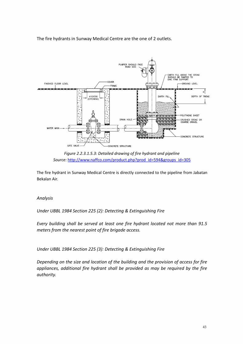
The fire hydrants in Sunway Medical Centre are the one of 2 outlets.
Figure 2.2.3.1.5.3: Detailed drawing of fire hydrant and pipelineSource: http://www.naffco.com/product.php?prod_id=594&groups_id=305
The fire hydrant in Sunway Medical Centre is directly connected to the pipeline from JabatanBekalan Air.
Analysis
Under UBBL 1984 Section 225 (2): Detecting & Extinguishing Fire
Every building shall be served at least one fire hydrant located not more than 91.5meters from the nearest point of fire brigade access.
Under UBBL 1984 Section 225 (3): Detecting & Extinguishing Fire
Depending on the size and location of the building and the provision of access for fireappliances, additional fire hydrant shall be provided as may be required by the fireauthority.

44
Figure 2.2.3.1.5.4: Location of External Fire Hydrant on ground floorin Sunway Medical Centre
According to Mr. Karmal, there are a total of 6 external fire hydrants in Sunway Medical Centre;located along the roadside of the building.

45
2.2.3.2 Non- Water Based System
2.2.3.2.1 Carbon Dioxide, CO2 Fire Suppression System
Carbon Dioxide is the combination of carbon & oxygen atoms which is odourless &colourless. Is it a type of inert gas which extinguishes fire by displacing oxygen.Besides, it acts as a heat sink which absorbs combustion energy and reduce thetemperature of flame when a fire breakout occurs.
Hence, Carbon Dioxide, CO2 Fire Suppression System is the most preferred choiceamong users as an extinguishment for a multitude of critical facilities. This is due toits adaptability to a wide range of hazards besides from being fast & effective inputting off fire.
Figure 2.2.3.2.1.1: Typical Carbon Dioxide (CO2) Fire Suppression System parts & ComponentsSource: http://www.enggcyclopedia.com/2011/11/carbon-dioxide-fire-fighting/
An automatic CO2 Extinguishing System consists of:1. CO2 cylinders2. Steel piping3. Discharge nozzles4. Heat and/ or smoke detectors5. Control Panel6. Visual & audio alarm system (activated before gas released)

46
Figure: 2.2.3.2.1.2 CO2 Fire Suppression System in Sunway Medical Centre
This system is normally used in tightly confined spaces (which is free of people &animal) such as:
1. Electrical equipment spaces: LV and MV switchgears, battery rooms, dieselgenerators areas, cable rooms, isolated and unmanned data centers.
2. Areas of storage, transport or handling of fuels.
Analysis
Under UBBL 1984 Section 236: Special Hazards
Places constituting special hazards or risks due to the nature of storage , trade,occupancy, or size shall be required to be protected by fixed installations, protectivedevices, systems and special extinguishers as may be required by the Fire Authority.
In Sunway Medical Centre, the CO2 Suppression System is installed in:
1. Consumer Room2. Transformer Room3. Gen Set Room

47
These rooms consist of various electrical appliances which cannot be applied withnormal water- based suppression system. Carbon Dioxide (CO2) must be usedinstead because the gas released is able to displace oxygen from the air; thusextinguishing the fire.
This respects to the requirement stated in UBBL.
Figure 2.2.3.2.1.3: Showing signboards on the door of Transformer & Consumer Room
No admittance is allowed to anyone except for certain authorized personnel only.Even authorized personnel have to be careful when manipulating and dealing withthe electrical appliances in both transformer & consumer room. This is because thereis a risk of fire outbreak occurring if not handled properly, or in worse case explosionhappens as they are all under high tension which is 11kV.
If a fire occurs in the electrical rooms, CO2 Fire Suppression System is the most idealsolution as carbon dioxide is not combustible & does not conduct electricity. Mostimportantly the system will not damage sensitive electric equipments in theelectrical room.

48
Besides, the system spread and discharge in the form of gas. Hence, when properlyventilated, there will be no residual clean- up needed.
Figure 2.2.3.2.1.4: Wire Mesh applied on the door of electrical rooms
Wire mesh is applied on the door of electrical rooms (transformer room, consumerroom) in order to create air vents for the room to be naturally ventilated and in thesame time to trap and block small insects from flying into the room.
Figure 2.2.3.2.1.5: Smoke Curtain in Consumer Room in Sunway Medical Centre
Smoke curtain can be found normally in electrical rooms.
Smoke curtain is meant to divert smoke away from a location or to protect an areafrom direct smoke infiltration. When there is a fire breakout, a signal allows thecurtain to unroll at a controlled rate and drop to a preset height. The curtain is set toa height where the smoke will be trapped inside (since smoke rises up high) whilepeople can still pass through the openings from below.
49
According to Metabilt Doors (2014), the curtain scan withstand hot air and smoke attemperature temperatures up to 1000 degree Celsius for an hour due to themicronized aluminium polymer fabric.
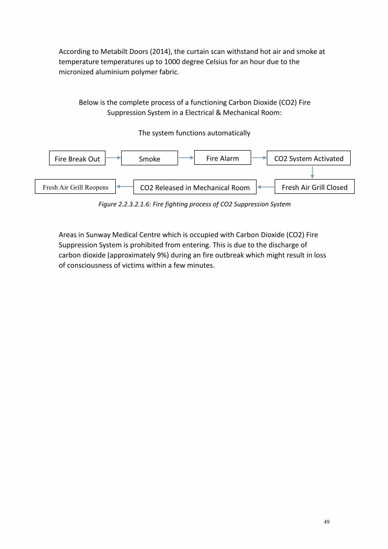
Below is the complete process of a functioning Carbon Dioxide (CO2) FireSuppression System in a Electrical & Mechanical Room:
The system functions automatically
Figure 2.2.3.2.1.6: Fire fighting process of CO2 Suppression System
Areas in Sunway Medical Centre which is occupied with Carbon Dioxide (CO2) FireSuppression System is prohibited from entering. This is due to the discharge ofcarbon dioxide (approximately 9%) during an fire outbreak which might result in lossof consciousness of victims within a few minutes.
Fire Break Out Smoke Fire Alarm CO2 System Activated
Fresh Air Grill ClosedCO2 Released in Mechanical RoomFresh Air Grill Reopens

50
4.2.3.2.2 Portable Fire Extinguisher
Portable fire extinguisher is an active fire protection device used to extinguish orcontrol small fires. Typically, a fire extinguisher consists of a hand-held cylindricalpressure vessel containing an agent which can be discharged to extinguish a fire.
Portable Fire Extinguisher
It is a small tube filled with different type of agent inside.
Type of Agent Colour Class of fire DescriptionWater Red A - Spray to 6~8 meters in 60~120 secondFoam Cream A & B - Spray to 6 meters in 30~90 secondCO2 Black B, C & E - 2.2kg gas
Halon Green E noneDry Powder Blue All classes - Spray to 5~6 meters in less than 2 minutes
- 9~12 kg
Figure 4.2.3.2.2.1: Fire Extinguishers (Water & CO2) in Sunway Medical Centre
Classification and use of fire extinguisher
Class Combustibles SpecificationA Wood/ Paper/ Plastics/ Textiles Green triangle containing letter ’A’B Flammable Liquid & Gas Fires (Oil/
Gasoline)Red square containing letter ‘B’
C Live Electrical Equipment Blue circle containing letter ‘C’D Combustible Materials (Magnesium,
etc...)Yellow 5 point- painted starcontaining letter ‘D’
K Cooking Media (Fats/ Greese/ Oils) Containing Letter ‘K’

51
Figure 4.2.3.2.2.2: 4 Steps in operating an fire extinguisherSource: http://apocalypseprep.blogspot.com/2010_03_01_archive.html
Figure 4.2.3.2.2.3: Sectional Cut of A Soda Acid Fire Extinguisher (Parts & Components)Source:
http://www.marineinsight.com/marine/marine-news/headline/different-types-of-fire-extinguishers-used-on-ships/
The fire extinguishers are to be checked and certified by the Jabatan Bomba once ayear. It is important to make sure that the pressure and content in the fireextinguisher is always sufficient.

52
Analysis
Under UBBL 1984 Section 227: Portable Extinguishers
Portable Extinguishers shall be provided in accordance with the relevant codes ofpractice and shall be sited in prominent positions on exit routes to be visible from alldirections and similar extinguishers in a building shall be of the same method ofoperation.
Figure 4.2.3.2.2.4: Location of Dry Powder Type Fire Extinguisher in Sunway Medical Centre2nd Floor
All the fire extinguishers are located at the corridor near to the fire escape lobbiesand can be easily seen. There are 10 fire extinguishers in level 2 of Sunway MedicalCentre, each placed next to the fire lift. This very much fulfills the requirementsstated in UBBL

53
2.3 Passive Fire Protection
2.1.2 Literature Review
By law, every building needs to have passive fire protection. It is to provide safety for the
users during an evacuation of fire. An effective passive fire protection can be done on a
building by considering the users of the building, the function of the building, the height of
the building and the type of the building. Users should be protected within the building
during the evacuation. Generally, the idea to escape the building is to provide escape route,
emergency access, uses of materials that have high fire resistant and not depending on the
operation of mechanical device.
A safe escape route is needed to provide safe surroundings for user to be able to leave the
building and gather at the assembly point safely, hence escape route need to be kept clear
from obstructions, so that there is a clear path for user, in order to keep it clear, some areas
are suggested to be emergency access. Besides, most of the time the escape routes are
normally located at areas which are less likely to be the starting point of fire. Some routes
are also being close/block in order to redirect users to the escape routes. Some building
include smoke chamber before entering the escape routes, normally windows are placed in
this chamber to filter out the smoke but some do it mechanically. Escape routes are also
well ventilated with windows or mechanically, this is to ensure sufficiency of oxygen within
the routes. Never the less, the materials that are used need to be fire resistance materials, it
is buy time for the users to leave the building, to prevent the spreading of the fire towards
the escape routes.

54
2.3.1 Site & Space Planning
Sunway Medical center is a building consists two blocks, Block A and Block B, both blocks have 6
floors. With a size of more than 112000 cubic meters, the building is built in the form of island site
and needed to reserve surrounding areas as perimeter of access for the emergency with minimum
6m width for the access road for fire brigade.
Figure 2.3.1 shows Ground floor plan with area indicated green as the reserved space for fire brigade.
UBBL:
Section 140:
All building in excess of 7000 cubic meters shall about upon a street or road or open space of
not less than 12 meters width and accessible to fire brigade appliances. The proportion of
the building abutting the street, road or open space shall be in accordance with the following
scale:

55
In figure 2.3.2, the red circled area is the fire risks area, whereas the green patch is the
potential spot to have the most users within this floor. Just as shown in the diagram, the
fire risk area is distance away from the area with most users. Never the less it is located at
the Lower Ground Floor, which is the floor with the least users, mostly consist of storage
and working space for staffs. The fire risk area is also located right beside open space in
order to ease fire brigade to handle the fire.
UBBL:
Section 139:
The following areas or uses shall be separated from the others areas of the occupancy in
which they are located by fire resisting construction of elements of structure of a FRP to be
determined by the local authority based on the degree of fire hazard:
a) Boiler rooms and associated fuel storage areas;
b) Laundries;
c) Repair shops involving hazardous processes and materials;
d) Storage areas of materials in quantities deemed hazardous;
e) Liquefied petroleum gas storage areas;
f) Linen room;
g) Transformer rooms and situations;
h) Flammable liquids stores.
Figure 2.3.2 Lower Ground floor plan

56
To separate fire risk area from the building effectively, fire rated doors, walls and floors are
constructed according to UBBL. With this, spaces within the building will be divided into
smaller compartments, it is to:
-Limits the spread of fire
-Restrict the movement of smoke
-Optimize evacuation routes during fire
2.3.2 Materials: (Duration of time in flame)
-Red brick wall and concrete (external wall):
4hours
-Light brick wall (internal wall):
4hours
-Partition wall with rock wool (internal wall):
Minimum 1 hour
-Mineral Fiber ceiling:
2 hours
-Vinel floor:
2 hours
-Fire rated door:
1 hour

57
UBBL: (Walls & Floors)
Section 136:
Any building, other than a single storey building, of a purpose group specified in the Fifth
Schedule to these By-laws and which has-
a) Any storey the floor area of which exceeds that specified as relevant to a building of
that purpose group and height;
or
b) A cubic capacity which exceeds that specified as so relevant shall be so divided into
compartment floors or both, that-
i) No such compartment has any storey the floor area of which exceeds the area
specified as relevant to that building; and
ii) No such compartment has cubic capacity which exceeds the area specified as
relevant to that building:
Provided that if any building is provide with an automatic sprinkler installation which
compiles with the relevant recommendations of the F.O.C. Rules for Automatic Sprinkler
Installation, 29th edition, this by-law has effect in relation to that building as if the limits of
dimensions specified are doubled.
Section 137:
In any buildings which exceeds 30 meters in height , any floor which Is more than 9 meters
above ground floor level which separates one storey from another storey, other than a floor
which is either within a maisonette or a mezzanine floor shall be constructed as a
compartment floor.
Section 138:
The following walls and floors in buildings shall be constructed as compartment walls or
compartment floors:
a) Any floor in a building of Purpose Group II (Institutional);
b) Any wall or floor separating a flat or maisonette from any other part of the same
building;
c) Any wall or floor separating part of a building from any other part of the same
building which is used or intended to be used mainly for a purpose falling within a
different purpose group as set out in the Fifth Schedule to these By-laws; and
d) Any floor immediately over a basement storey if such basement storey has an area
exceeding 100 square meters.

58
UBBL: (Fire rated doors)
Section 162:
(1) Fire doors of the appropriate FRP shall be provided.
(2) Openings in compartment walls and separating walls shall be protected by a fire door
having a FRP in accordance with the requirements for that wall specified in the Ninth
Schedule to these By-laws.
(3) Openings in protecting structures shall be protected by fire doors having FRP of not less
than half the requirement for the surrounding wall specified in the Ninth Schedule to these
By-laws but in no case less than half hour.
(4) Openings in partition enclosing a protected corridor or lobby shall protected by fire doors
having FRP of half-hour.
(5) Fire doors including frames shall be constructed to a specification which can be shown to
meet the requirements for relevant FRP when tested in accordance with section 3 of BS
476:1951.

59
Section 163:
Fire doors conforming to the method of construction as stipulated below shall be deemed to
meet the requirements of the specified FRP:
a) Doors and frames constructed in accordance with one of the following specifications
shall be deemed to satisfy the requirements for doors having FRP of half-hour:
(i) a single door 900 millimeters wide x 2100 millimeters high maximum of double
doors 1800 millimeters x 2100 millimeters high maximum constructed of solid
hardwood core of not less than 37 millimeters laminated with adhesives conforming
to either BS.745 “Animal Glue”, or BS 1204, “Synthetic resin adhesives (phenolic
and aminoplastic) for wood” Part 1, “Gap-filling adhesives”, or BS 1444, “Cold-
setting casein glue for wood”, faced both sides with plywood to a total thickness of
not less than 43 millimeters with all edges finished with a solid edge strip full width of
the door. The meeting stiles of double doors shall be rabbeted 12 millimeters deep or
may be butted provided the clearance is kept to a minimum;
(ii) doors may be double swing provided they are mounted on hydraulic floor springs
and clearances at floor not exceeding 4.77 millimeters and frame and meeting stiles
not exceeding 3 millimeters;
(iii) a vision panel may be incorporated provided it does not exceed 0.065 square
meter per leaf with no dimension more than 1370 millimeters and it is glazed with 6
millimeters Georgian Wired Glass in Hardwood stops;
(iv) doors constructed is accordance with BS No. 459: Part 3: 1951 Fire Check Flush
Doors and Wood and Metal frames (Half-Hour Type);
(v) timber frames for single swing half-hour fire doors of overall width of 60
millimeters including 25 millimeters rabbet and depth to suit door thickness plus 34
millimeters stop;
(vi) metal frames for half-hour fire doors shall be of sheet steel not lighter than 18
gauge of overall width 50 millimeters including 18 millimeters rabbet and depth to
suit the door thickness plus 53 millimeters stop;
(vii) timber or metal frames for double swing doors shall be as specified above with
minimum clearance between frame and door;
b) Doors and frames constructed in accordance with one of the following specifications
shall be deemed to satisfy the requirements for door having FRP of one hour:
(i) a single door not exceeding 900 millimeters wide x 2100 millimeters high or
double doors not exceeding 1800 millimeters x 2100 millimeters high constructed as
for specification (a) for half-hour but incorporating on both faces a layer of asbestos
insulating board to BS 3536 (not asbestos cement) not less than 3 millimeters thick;|
(ii) doors may swing one way only and double doors shall have 12 millimeters wide
rabbet at the meeting stiles;
(iii) a vision panel may be incorporated provided it does not exceed 10 square meters
per leaf with no dimension more than 300 millimeters and it is glazed with 6
millimeters Georgian Wire Glass in hardwood stop;
(iv) doors constructed in accordance with BS 459: Part 3: 1951: Fire Check Flush
60
Doors and Wood and Metal frames (One Hour Type);
(v) frames for one hour doors shall be as for half-hour door except that timber frames
shall be pressure impregnated with 15% go 18% solution of monoammonium
phosphate in water.
Section 164:
(1) All the fire doors shall be fitted with automatic door closers of hydraulically spring
operated type in the case of swing doors and of wire rope and weight type in the case of
sliding doors.
(2) Double doors with rabbeted meeting stiles shall be provided with coordinating device to
ensure that leafs close in the proper sequence.
(3) Fire doors may be held open provided the hold open device incorporates a heat actuated
device to release the door. Heat actuated devices shall not be permitted on fire doors
protecting openings to protected corridors or protected staircases.
Section 217:
Fire Resistance of Structural Member Any structural member or overloading wall shall have
fire resistance of not less than the minimum period required by these By-Laws for any
element which it
Analysis:
Passive fire protection is a planning matter and must be considered at the planning stage in
the building design in order to allocate fire risk area away from the building spaces. An
effective passive fire protection shows good planning and good design. As prevention is
better than cure, is better to prevent fire from spreading into the building than having to
put out the fire. Hence, material choice are all fire rated to slow down the spreading of fire.
Never the less, designing according to UBBL ensure that the passive fire protection system is
able to correspond well with the building as different buildings possess different size,
function and users.
61
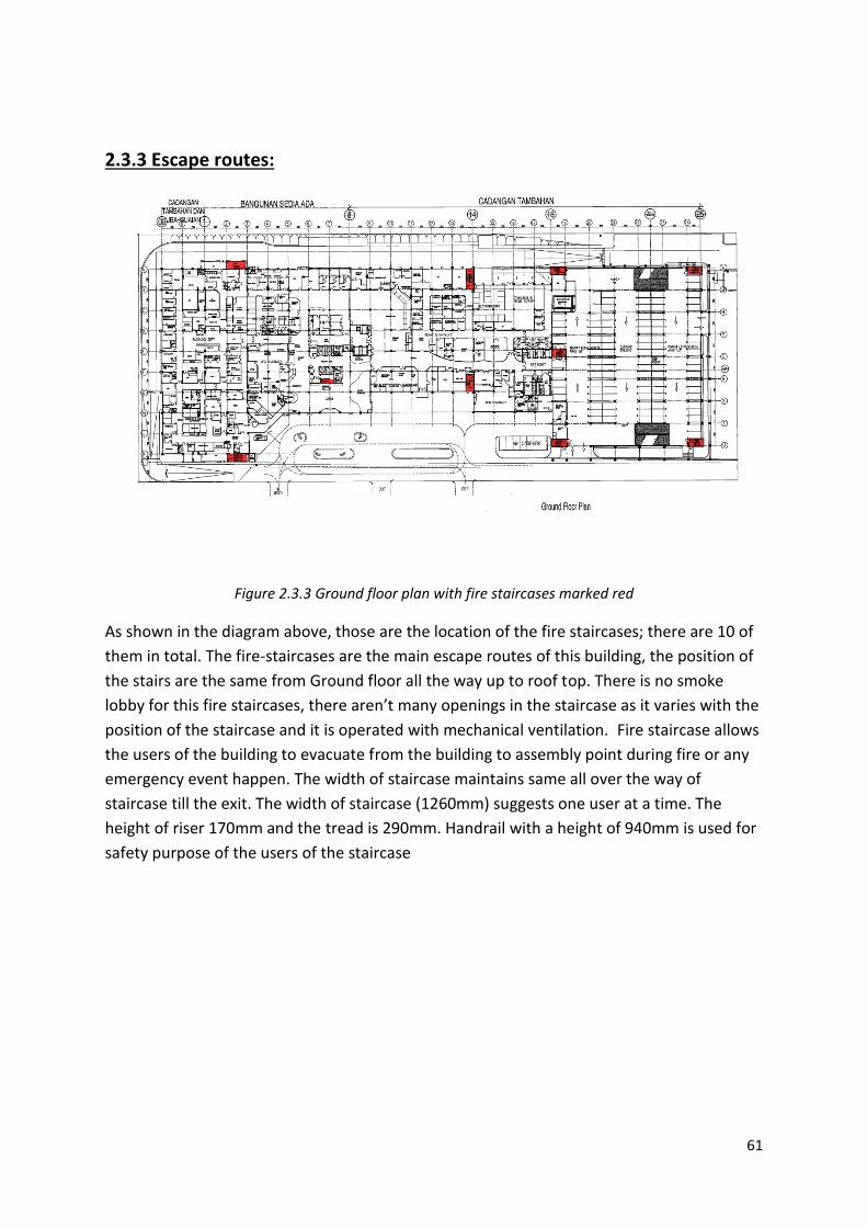
2.3.3 Escape routes:
Figure 2.3.3 Ground floor plan with fire staircases marked red
As shown in the diagram above, those are the location of the fire staircases; there are 10 of
them in total. The fire-staircases are the main escape routes of this building, the position of
the stairs are the same from Ground floor all the way up to roof top. There is no smoke
lobby for this fire staircases, there aren’t many openings in the staircase as it varies with the
position of the staircase and it is operated with mechanical ventilation. Fire staircase allows
the users of the building to evacuate from the building to assembly point during fire or any
emergency event happen. The width of staircase maintains same all over the way of
staircase till the exit. The width of staircase (1260mm) suggests one user at a time. The
height of riser 170mm and the tread is 290mm. Handrail with a height of 940mm is used for
safety purpose of the users of the staircase

62
UBBL: (staircase)
Section 168:
1. Except as provided for in by-law 194 every upper floor shall have means of egress via
at least two separate staircases.
2. Staircase shall be of such width that in the event of any one staircase not being
available for escape purposes the remaining staircases shall accommodate the
highest occupancy load of any one floor discharging into it calculated in accordance
with provisions in the Seventh schedule to these By- Laws.
3. The required width of a staircase shall be the clear width between walls but
handrails may be permitted to encroach on this width to a maximum of 75 millimetres.
4. The required width of a staircase shall be maintained throughout its length including
at landings.
5. Doors giving access to staircases shall be so positioned that their swing shall at no
point encroach on the required width of the staircase or landing.
Section 189:
1. Every staircase provided under these By-Laws in a building where the highest floor is
more than 1200 millimetres above the ground level, or in any place of assembly, or in
any school when such staircase is used as an alternative means of escape shall be
enclosed throughout its length with fire resisting materials.
2. Any necessary openings, except openings in external walls which shall not for this
By-Law include wall to air-wells, in the length of such staircase shall be provided
with self-closing door constructed of fire resisting materials.
Section 200:
For staircases in building exceeding 18 metres above ground level are not ventilated in
accordance with by-law 198, two alternative methods of preventing the infiltration of smoke
into the staircase enclosures may be permitted by providing-
a) Permanent ventilation at the top of the staircase enclosure of not less than 5% of the
area of the enclosure and in addition at suitable intervals in the height of the
staircase a mechanically ventilated shaft to achieve not less than 20 air changes per
hour to be automatically activated by a signal from the fire alarm panel; or
b) Mechanical pressurisation of the staircase enclosure to the standard of performance
as specified in section 7 of the Australian Standard 1668, Part 1-1974 or any other
system meeting the functional requirements of the D.G.F.S.

63
Figure 2.3.4 First floor with red mark as fire staircases and blue mark as main spaces with users
As shown in figure 4.2.2 the blue highlighted parts are potential places with certain amount
of users consist of patients and staffs of the hospital. The numbers of stairs were determine
by the dimension of the entire floor, as according to UBBL’s Seventh schedule, there is a
limit for travel distance for each different types of buildings. Not only for the travel distance
of the entire floor, for each rooms there is a maximum travel distance from each corner of
the room which should not be exceed.

64
UBBL:
Section 165:
1. The travel distance to an exit shall be measured on the floor or other walking surface
along the centre line of the natural path of travel, starting 0.300 metre from the most
remote point of occupancy, curving around any corners or obstructions with 0.300
metre clearance therefrom and ending at the storey exit. Where measurement includes
stairs, it shall be taken in the plane of the trend noising.
2. In the case of open areas the distance to exits shall be measured from the most remote
point of occupancy provided that the direct distance shall not exceed two-third the
permitted travel distance.
3. In the case of individual rooms which are subject to occupancy of not more than six
persons, the travel distance shall be measured from the doors of such rooms:
provided that the travel distance from any point in the room to the room door does not
exceed 15 metres.
4. The maximum travel distances to exits and dead end limits shall be as specified in the
Seventh Schedule of these By-laws.
Section 166:
1. Except as permitted by by-law 167 not less than two separate exits shall be provided
from each storey together with such additional exits as may be necessary.
2. The exists shall be so sited within the limits of travel distance as specified in the
Seventh Schedule to these By-laws and are readily accessible at all times.
Section 168:
1. Except as provided for in by-laws 194 every upper floor shall have means of egress
via at least two separate staircases.
2. Staircase shall be of such width that in the event of any one staircase not available for
escape purpose the remaining staircase shall accommodate the highest occupancy
load of any one floor discharging into it calculated in accordance with provisions in
the Seventh schedule to these By-laws.
3. The required width of a staircase shall be clear width between walls but handrails
may be permitted to encroach on this width to a maximum of 75 millimetres.
4. The required width of a staircase shall be maintained throughout its length including
at landings.
5. Doors giving access to staircase shall be so positioned that their swing shall at no
point encroach on the required width of the staircase or landing.

65
Section 174:
1. Where two or more storey exits are required they shall be spaced at not less than 5
metres apart measured between the nearest edges of the openings.
2. Each exit shall give direct access to-
(a) a final exit;
(b) a protected staircase leading to a final exit; or
(c) an external route leading to a final exit.
3. Basements and roof structures used solely for services need not be provided with
alternatives means of egress.
2.3.4 Assembly point:
Figure 2.3.5 the yellow area is the assembly point, the red arrows indicate path ways to the assembly
point from the fire staircases.
As shown above, the assembly point is located at an open space right outside the hospital.
Each staircase is provided with more than one route to reach the assembly point just in case
some routes are blocked. The assembly point is normally classified with different class
according to the capacity of users, for Sunway Medical Centre, it is classified as Class A
because it has more than 1000 users in this building.

66
UBBL:
Section 178:
In buildings classified as institutional or places of assembly, exits to a street or large open
space, together with staircases, corridors and passages leading to such exits shall be located,
separated or protected as to avoid any undue danger to the occupants of the place of
assembly from fire originating in the other occupancy or smoke therefrom.
Section 179:
Each place of assembly shall be classified according to its capacity as follows:
Class A- Capacity- 1000 persons or more
Class B- Capacity- 300 to 1000 persons
Class C- Capacity- 100 to 300 persons
Section 180:
The occupancy load permitted in ay place of assembly shall be determined by dividing the
net floor area or space assigned to use by the square metre per occupant as follows:
a) Assembly area of concentrated use without fixed seats such as an auditorium, places
of worship, dance floor and lodge room- 0.65 square per person;
b) Assembly area of less concentrated use such as a conference room, dining room,
drinking establishment, exhibit room, gymnasium, or lounge- 1.35 square metre per
person;
c) Standing room or waiting space- 3 square metres per person;
d) The occupancy load of an area having fixed seats shall be determined by the number
of fixed seats installed. Required aisle space serving the fixed seats shall not be used
to increase the occupants load.
Section 188:
Exits in any place of assembly shall be arranged that the travel distance from any point to
reach an exit shall not exceed 45 metres for unsprinkled buildings and 60 metres for
sprinkled buildings.

67
Analysis:
Escape routes are meant to lead to a safety place without relying on others. It is to make it
possible for users of the buildings to reach a spot of safety. Safe assumption can be made
such as there is only one source of fire; hence alternate routes need to be provided. Never
the less, passive fire protection need put in consideration of the building form, the function
of the building, the potential fire risk areas.
Figure 2.3.6 Assembly point

68
3. AIR CONDITIONING AND MECHANICAL VENTILATION SYSTEM 3.1 Literature Review
Air conditioning systems are important for a building in order to enhance the indoor air
quality. It provides a healthier and more comfortable environment to users. This system
always serves as four main functions: control air temperature, control air humidity, control
air circulation and to control air quality which are the four main factors who affect thermal
comfort.
For our case study building, Sunway Medical Centre, which consisting two block of 6 storey
tower, requires a large amount of cooling load. Air-conditioning system are used as cooling
strategy for two towers of Sunway Medical Centre to ensure sufficient fresh air are provided
in those building through air circulation. It is vital for a hospital to provide sufficient fresh air
to patients and exhaust the polluted air. Due to those requirements, centralized/plant air-
conditioning system is chosen to serve the entire building.
There are normally four kind of systems on market which are:
Room air-conditioner (window unit)
Split unit air-conditioning system
Packaged unit air conditioning system
Centralized/plant air-conditioning system
Centralized/plant air-conditioning system
There are two common cycle, Refrigerant cycle and Air cycle are involved in centralized air-
conditioning system.
Refrigerant cycle
is a process to remove heat from one place to another. By the way, heat inside a room is

69
transferred through the evaporator and removed to the outside air through a condenser.
This cycle usually done in cooling tower which consisted both components.
Evaporator is a coil of pipe where the refrigerant inside it is vaporizing and absorbing heat. The
function is to provide a heat-absorbing surface and release the heat when air blown over the surface
of this pipe. While condenser rejects the heat absorbed by the evaporator. The refrigerant changes
from a vapour to a liquid in the condenser.
Air cycle
is a process to distribute treated air into the room that needs to be conditioned. Latent heat inside
the room is removed when the return air is absorbed by the evaporator. The medium to absorb the
heat can be either air or water. Distribution of air can be either through ducts or chilled water pipes.
Heat inside the room is removed and slowly the internal air becomes cooler.

70
3.2 Schematic Diagram of Operation System
CHWS : Chilled Water Supply CHWR : Chilled Water Return CDWS : Condensed Water Supply CDWR : Condensed Water Return CHWP : Chilled Water Pump CWP : Condensed Water Pump
Figure 3.2.1 Schematic Diagram of Sunway Medical Centre ( Yiew, 2014)
In this huge building , there are two units of cooling tower for each Tower A and Tower B
which each unit consisted 700rt (refrigerant tonnage) in cubical and rounding style. By the
way, the cooling tower is used to cool down the condensed water from four chillers in
Sunway Medical Centre from both tower A & B, which each unit consisted 500rt (refrigerant
tonnage). Besides, there are total 81 units of AHU in Sunway Medical Centre and act as a
major system to ventilate the whole building , 25 units in tower A and another 56 units in
tower B. Furthermore, there have frequency inventors in tower B to monitor the condition
and make adjustment in order to save energy. Apart from that, there are 138 units of fan
coils in tower A, while 102 units in tower B.

71
Figure 3.2.2 Operation System of the centralized/plant air-conditioning system
Cooling Tower
•To cool downthe warm water pumped up by the condenser
•While condenser is to suck up the heat from the chiller water loop
•The water is cooled down and ready to recirculate, meanwhile heat is released to atmosphere
Chiller
•Transfer heat (warmed water) from AHU to condenser .
•The chilled water is pumped to AHU after the transfered the heat to condenser.
Air Handling System
•For heating, cooling, humidifying, dehumidifying, filtering and distributing air
Airduct
•To distribute the air from AHU to the rooms that need to be air-conditioned
Diffuser
•Opening who providing the fresh air from AHU.
Return airduct
•Duct who returning polluted or warmed air back to AHU room to cool down or filtering.
Fan Coil System
( FCU)

72
3.3 Cooling Tower
Figure 3.3.1 Typical Schematic Diagram of Cooling tower http://imgarcade.com/1/water-cooling-tower/
The cooling tower is used to cool down the chiller plant. In Chiller, the hot vapours from
evaporator enter the condenser and are cooled down by the water from the cooling tower
that circulates through the condenser. The vapours move through the tubes of the
condensers releasing heat to the water. After the heat exchange in chiller plant, the hot
water releases the heat to atmosphere in cooling tower through natural convection and
major based on evaporation. Once the water is cooled down and it is ready to recirculate
and pump to the chiller by condensed water pump (CWP). Furthermore, cooling tower
usually located at windy place to fully utilize natural convection.
Figure 3.3.2 Cooling Tower which located on rooftop. ( Kiew ,2014)
CDWR- Condensed Water Return
from the chilled water loop
CDWS- Condensed Water which
ready to circulate again
Louvres to allow natural
convection
Fan Stack

73
Figure 3.3.3 Location of Cooling Tower on rooftop

74
3.3.1 Condensed Water Pump ( CWP)
CWP, Single well pump tanks are reservoirs for chilled water and tower cooling water
processes. Process pump(s) deliver water through the
chiller or cooling tower as well as through the process.
Dual well tanks have re-circulation pump(s) to deliver
water from the hot side to the chiller or tower. The
water then returns to the cold side, where process
pump(s) deliver cooled water directly to process.
(ASHRAE,2008)
Standby pumps may be used as backups for both
process and re-circulation during service or
maintenance procedures. Manifolding options provide
ease of connection to process and can ease the
transition to standby pumps. (ASHRAE,2008)
Figure 3.3.1.1 Condensed Water Pump in Sunway Medical Centre
Figure 3.3.1.2 Condensed Water Pump with in Standby mode

75
3.3.2 Water Tank
Figure 3.3.2.1 Schematic Diagram between Cooling tower and Water tank (Yiew, 2014)
From the schematic diagram of the cooling tower, there is an expansion water tank
connected with cooling tower. As there might be some water loses, when releasing heat by
evaporation, hence the expansion water tank is make up to add on the water loses.
Figure 3.3.2.2 Water Tank which located behind cooling tower on rooftop (Kiew, 2014)

76
3.4 Chiller Plant
Figure 3.4.1 Schematic Diagram of Chiller system in Sunway Medical Centre (Yiew, 2014)
The Sunway Medical Centre building had applied the chilled water system with air cooled
condenser to cool the refrigerant. From Figure 3.4.2, it clearly shows that there are two
main components in chiller plant which are Condenser and Evaporator.
In the heat absorption cycle uses water as the refrigerant and lithium bromide as the
absorbent. The water is cooled by the refrigerant as it passes through the evaporator. On
the other side of the evaporator the refrigerant evaporates to cool the water, then passes
through a compressor and condenser, rejecting the heat to the ambient air. After the
process of heat releasing, the chilled water is cooled down to a very low temperature which
between 6 to 8 degree Celsius.
By then, the chilled water are pumped to different level for two part of system. The two
systems are AHU (Air Handling Unit) and FCU (Fan Coil Unit), which consist of cooling coil.
The chilled water will flow through cooling coil, and absorb the heat from blower of AHU or
FCU which pass through it. Afterward, the chilled water will be pumped back to the chiller
plant by CHWP (Chilled Water Pump) and ready to recirculate.

77
Figure 3.4.2 Typical Schematic Diagram of how internal of chiller works. http://www.lytron.com/Tools-and-Technical-Reference/Application-Notes/Selecting-a-Cooling-
System
Figure 3.4.4 Chilled Water Pump (CHWP)
(Kiew, 2014)
Figure 3.4.3 Chiller which comprise two
component for heat exchange (Kiew,
2014)

78
Figure 3.4.7 Pressure Indicator on CDWS and CDWR (Kiew, 2014)
Figure 3.4.5 The piping of CDWR
and CDWS from Cooling tower to
Chiller (Kiew, 2014)
Figure 3.4.6 Pressure Indicator on Chiller
(Kiew, 2014)
CDWR
CDWS

79
Figure 3.4.8 Location of Chiller Plant Room on Lower Ground Floor at Sunway Medical Centre
Relief devices should be located at least 20 feet away from any relief opening, and at least
15 feet removed from ground level. (ASHRAE,2008). Due to the chiller plant create certain
noise pollution, hence it being located at lower ground floor which sits beside car par.
Figure 3.4.9 Signboard outside the Chiller Plant Room (Kiew, 2014)

80
3.4.1 Component of Chiller Plant
Figure 3.4.1.1 Schematic Diagram of how internal of Chiller works http://www.lytron.com/Tools-and-Technical-Reference/Application-Notes/Selecting-a-Cooling-
System
Compressor:
It removes the refrigerant vapour from the evaporator and reduces the pressure in the
evaporator to a point where the desired evaporating temperature can be maintained.
Evaporator:
From Figure 3.2.1.2, the evaporator is the device in which liquid refrigerant boils, absorbing
heat as it evaporates, cooling the process fluid.
Condenser: The refrigerant vapour migrates through mist eliminators to the condenser tube
bundle. The refrigerant vapour condenses on the tubes. The heat is removed by the
condensed water which moves through the inside of the tubes.
Figure 3.4.1.2 Schematic Diagram of Chiller Plant in Refrigerant Circui http://www.advantageengineering.com/schematics/mkaSchematic.php?NU=20t

81
3.5 HVAC (Heating, Ventilation and Air Conditioning) System
According to UBBL laws: 41(2) Any application for the waiver of the relevant by-laws shall
only be considered if in addition to permanent air-conditioning system there is provided
alternative approved means of ventilating the air-conditioned enclosure, such that within
half an hour of air-conditioning.
Air Handling Units (AHU) and Fan Coil Unit (FCU) are HVAC system that widely used in
Sunway Medical Centre. AHU is generally a bigger system than FCU and it is more complex
than the FCU and that AHU are often used in bigger establishments or public spaces, such as
corridor, offices and lobby; meanwhile FCU are used in smaller space such as treatment
rooms, ICU (Intensive Care Unit) and OT (Operation Theatre), it can make adjustment about
temperature based on the user’s need as it is in small particular unit. Both act as a major
role in providing fresh and clear air to Sunway Medical Centre. Furthermore, for Tower B, it
undergoes with BAS (Building Automation System) which monitor by computer.
Both AHU and FCU are comprised with three basic components: cooling coil, blower and
filter. In the system, the fresh air is cooled down by cooling coil when pass through it. After
that , the cooled air blow out to the particular room through blower via the duct.
MS 1525:2007:
8.10 ACMV system equipment
ACMV system equipment provides, in one (single package) or more (split system) factory
assembled packages, means for air-circulation, air-cleaning, air-cooling with controlled
temperature and dehumidification. The cooling function may be either electrically or heat
operated, and the refrigerant condenser may be air, water or evaporative-cooled.
Where the equipment is provided in more than one package, the separate packages should
be designed by the manufacturer to be used together.
9.91 Energy management System (EMS)
The Energy Management System (EMS) is a subset of the building Automation system (BAS)
function. It should be considered for buildings having area greater than 4000m2 of air-
conditioned space. Generally, a building automation system has three function:
a) Control of equipment;
b) Monitoring of equipment; and
c) Integration of equipment sub-systems

82
9.2 Control of equipment
The purpose of the control of equipment is to save energy. This is performed by the EMS
function of the building automation system.
9.3 Monitoring of equipment
The purpose of monitoring the equipment is to improve the efficiency of operations by:
a) Providing centralised information of current equipment conditions;
b) Providing historical information of equipment conditions;
c) Providing a “management by exception” function to alert the operator of any abnormal
Equipment conditions; and
d) Providing analysis tools to aid the study of equipment operations.
9.4 Integration of equipment subsystems
Equipment subsystems are integrated for the purpose of improving:
a) safety/security; for example, in the event of a fire, air-handling units can be used to create
a sandwich system for smoke control;
b) Indoor air quality; for example, by utilising the smoke purging system for periodic air
purging to achieve good indoor air quality;
c) Information management; by allowing information from multiple equipment subsystems
to be stored and reported in a consistent format; and
d) Overall system reliability; the intelligent controller of an equipment subsystem may be
configured to provide redundancy as a standby unit for another system/s without incurring
additional cost
9.6.3 Terminal Units
Terminal units include variable air volume (VAV) boxes, fan coil units (FCU) and split units
should be started and stopped by the EMS. Some applications may require a number of fan
coil units or split units to be grouped together as a common zone for start and stop control
by the EMS.

83
Besides, when compare the floor plans (Figure 3.5.1 and 3.5.2) of building and location of
the AHU and FCU units, we found that the units are always install at the higher floor than
the ducts.
Figure 3.5.1 Air Handling Units and Fan Coil Unit which are installed at fourth floor. (Kiew, 2014)
Figure 3.5.2 Rooms that having the diffuser of AHU and FCU at third floor.

84
3.5.1 Air Handling System
According to MS1525, 9.6.2 Air handling units (AHU) ,next to the chiller, the air handling
units are typically the largest consumers of energy in the building. The EMS should have the
facility to start and stop the air handling units based on a time schedule. For further energy
savings, the cooling coil valve of the air handling units should be controlled by an intelligent
controller which integrates with the EMS
In Sunway Medical Centre, there are two kind of Air Handling System. The CAV (Constant
Air Volume) are used in the older tower, Tower A and VAV (Variable Air Volume) are used
in Tower B. Variable air volume (VAV) system is a new technology and intended to save
energy and maintain comfortable temperatures in many individual zones or areas. There are
variable air volume dampers at the end of each supply duct branch which control the
volume of air delivered to a zone. The VAV dampers are controlled by a thermostat located
in the zone. The return and supply air dampers work in concert with the VAV controls in
order to vary the volume of supply air to the ventilation system at any given time.
The mechanism of AHU are simple and straight forward, the fresh air is cooled down when
flow through the cooling coil which fluids with a very low temperature chilled water from
chiller. In Figure 3.5.1.1 show obviously about the difference between temperatures of
chilled water supply and return. Besides, it also shows significant difference between
temperature of supply air and return air.
Figure 3.5.1.1 Schematic Diagram of AHU system of Sunway Medical Centre are shown in computer management software (Kiew, 2014)
RETURN AIR
FRESH AIR
COOLING COIL
CHWS Temp 7.31˚C
CHWR Temp 17.69 ˚C
SUPPLY AIR
SUPPLY AIR Temp
16.99 ˚C
RETURN AIR Temp
24.48 ˚C

85
Figure 3.5.1.2 Based on part of floor plan, can found that the AHU system are used for bigger establishments such as along the corridor. (Kiew, 2014)
Figure 3.5.1.3 Both Air diffuser and return air grille can be found easily in the office and along the corridor. (Kiew, 2014)
Return Air Grille
Air Diffuser
Figure 3.5.1.4 The Filter of AHU system (Kiew, 2014)

86
2.5.2 Fan Coil System (FCU)
In Sunway Medical Centre, Fan Coil System is adapted for room by room as it can make
adjustment by thermostat to suit the patient’s thermal comfort zone and saving energy
some more. The mechanism of cooling down the fresh air from outside is same as AHU (Air
Handing Unit). The fresh air flow over the filter and being cooled down by cooling coil. An
exposed fan coil unit may be wall-mounted, freestanding or ceiling mounted, and will
typically include an appropriate enclosure to protect and conceal the fan coil unit itself, with
return air grille and supply air diffuser set into that enclosure to distribute the air.
Furthermore, it doesn’t have a certain duct for transferring air.
Figure 3.5.2.1 Typical schematic diagram of FCU http://www.feta.co.uk/associations/hevac/specialist-groups/fan-coil-unit-group
Figure 3.5.2.2 From the part of the plan, we can identify that FCU serves by rooms (Yiew, 2014)
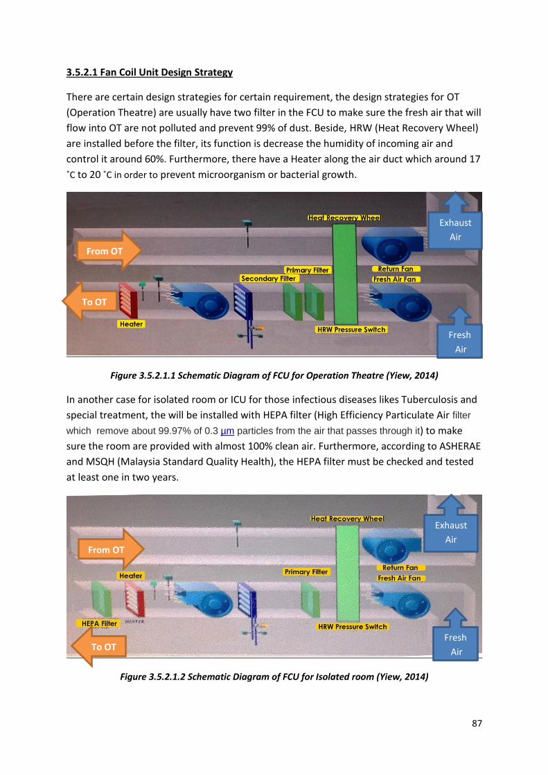
87
3.5.2.1 Fan Coil Unit Design Strategy
There are certain design strategies for certain requirement, the design strategies for OT
(Operation Theatre) are usually have two filter in the FCU to make sure the fresh air that will
flow into OT are not polluted and prevent 99% of dust. Beside, HRW (Heat Recovery Wheel)
are installed before the filter, its function is decrease the humidity of incoming air and
control it around 60%. Furthermore, there have a Heater along the air duct which around 17
˚C to 20 ˚C in order to prevent microorganism or bacterial growth.
Figure 3.5.2.1.1 Schematic Diagram of FCU for Operation Theatre (Yiew, 2014)
In another case for isolated room or ICU for those infectious diseases likes Tuberculosis and
special treatment, the will be installed with HEPA filter (High Efficiency Particulate Air filter
which remove about 99.97% of 0.3 µm particles from the air that passes through it) to make
sure the room are provided with almost 100% clean air. Furthermore, according to ASHERAE
and MSQH (Malaysia Standard Quality Health), the HEPA filter must be checked and tested
at least one in two years.
Figure 3.5.2.1.2 Schematic Diagram of FCU for Isolated room (Yiew, 2014)
From OT
To OT
Exhaust
Air
Fresh
Air
Exhaust
Air
Fresh
Air
From OT
To OT

88
3.6 Pressurization and Exhaust System
Based on different hygiene condition required, the pressurization and Exhaust system are
adapted in Sunway Medical Centre. In this building, there are total seven negative isolated
room and 2 positive rooms. Those negative isolated room are usually served to patient who
got infectious disease. Although the treatment rooms are in isolated status, they still might
chances for bacteria or microorganism to flows out the room. Hence, by making the air
pressure become negative, it can prevent the indoor air flows out. The only ways which
allow the air flow out is return air grille with HEPA filter, and return the filtered air to
atmosphere. Furthermore, according to ASHRAE, there must be six metre far from the duct
where take in fresh air and exhaust the filtered air .
Besides, AHU filter room also being controlled as a negative status in order to encourage the
room to suck in the air to filtering again. Apart from that, the toilet too being in negative
status to prevent the dirty air flows into building.
By the way, special devices are used to determine the pressure of a room and always
regulates the value of pressure about 2.5 and above for positive room; 2.5 and below for
negative room.
Figure 3.6.1 HEPA filter http://www.pleated-airfilter.com/sale-465324-glass-fiber-h13-h14-deep-separator-pleated-hepa-
filter-with-low-initial-resistance.html

89
4. ELECTRICAL SUPPLY SYSTEM
In Malaysia, Tenaga Nasional Berhad (TNB) is the largest electricity utility and a leading
utility company in Asia. The Company serve an estimated 8.3 million customers in
Peninsular Malaysia, Sabah and Labuan. TNB has been keeping the Lights On in Malaysia
ever since it was set up as the Central Electricity Board in 1949, powering national
development via the provision of reliable and efficient electricity. Malaysia uses various kind
of sources to produce energy such as hydro powered, natural gas, coal, solar power and etc.
Nonetheless, about 75% of energy used is generated by natural gas, which is not sustainable,
therefore we encourage new buildings to be energy efficiency at the same time,
encouraging the usage of renewable energy such as wind and solar energy.
4.1 Literature Review
In the world today, human lives with energy, especially in city. Electricity upgraded the
standard of living, making our life better and easier, almost everything automated require
electricity supply. Therefore the relationship of human and electricity is almost impossible
to be separated. Electricity is everywhere in the world, even in the human nervous system,
flowing to get you moved.
Electric power is the rate at which electric energy is transferred by an electric circuit. The SI
unit of power is the watt, one joule per second.
Nevertheless, as the world is advancing, more and more electricity power will be generated
to fulfill the needs of everything. Electric starts to take over many other energy contributors
such as fossil fuel, coal, oil and etc. because burning fossil fuel and coal are expensive yet
will produce harmful byproducts that will cause harm to mother earth.
Figure 4.1.1 Chimneys of Malaysia (Source: http://chimneysofmalaysia.blogspot.com/2010/03/)

90
Figure 4.1.2 Electrical Power Supply System Schematic Diagram (Source: http://www.brooksidestrategies.com/resources/origins-and-evolution-of-the-electric-grid/)
Diagram above shows the power supply system, electric generated will first pass through
the step-up transmission station which current will be raised by using step-up transformer
and transfer through HV transmission Lines, then go into step-down transmission substation
before it starts to distribute for customer usage. In Malaysia, there are three main types of
consumer, industrial, commercial and residential. Each of everyone will be charged in
different rate according to the amount of consumption.

91
4.2 The electricity supply system in Sunway Medical Centre
Figure 4.2.1 Sunway Medical Centre LG Floor Plan highlighting location of electrical rooms
Figure 4.2.2 Sunway Medical Centre zoom in location of electrical rooms

92
Figure 4.2.3 Schematic diagram showing the main electrical routing in Sunway Medical Centre

93
4.3 High Voltage Room: TNB Substation
The TNB substation is the direct link from compact
TNB substation. First of all, there are 2 main high
voltage incoming powers from TNB into the
Sunway Medical Centre TNB substation, both are
11kV. Then they’ll be transferred to the consumer
room, which is located beside TNB room. Electrical
rooms are located next to each other to reduce the
amount of voltage drop when transferring. The
longer the cable, the higher the voltage drop.
Although the TNB substation is located inside
Sunway Medical Centre, but it is owned by TNB,
one cannot simply enter without the permission of
TNB.
Figure 4.3.1 TNB room (Source: Kiew)
Figure 4.3.2 Zoom in floor plan highlighting TNB room

94
4.4 High Voltage Room: Consumer Room
The consumer room is connected to the TNB
Substation next door, it receives the 2x 11kv
current from TNB. Then the 11kV will be
transferred to transformer room which is just next
to the consumer’s room, transformers will step
down the high voltage to 415V.
Figure 4.4.1 Consumer Room with Danger
sign board (Source: Kiew)
Figure 4.4.2 Zoom in floor plan highlighting location of Consumer room

95
4.4.1 High Tension Switch Gear
These high tension switch gear are located inside
the consumer room, showing the incoming
voltage from TNB Substation. The meters is to
ensure the incoming Voltage of TNB is stable,
provide protection against overload current and
short circuit.
Figure 2.4.3 High Tension Switch Gear Figure 2.4.4 High Tension Switch Gear Meters (Source: Kiew) (Source: Kiew)
4.4.2 TNB Meters
TNB meters are located in the consumer’s room
where electric current usage will be calculated.
There are four meters, two are for normal usage
which another two are standby meters. There
need to be standby meters incase if any problem
occurs to the meter, TNB can still get the
accurate usage of electricity consumed by
Sunway Medical Center every month.
Figure 4.4.5 TNB meters (Source: Kiew)

96
4.4.3 Rubber Mats Flooring
Based on Electricity Supply Act 1990 and
Electricity Regulation 1994, rubber mats
should be placed on the floor beside
electrical boards in every electrical rooms as
a safety equipment for the maintenance
users. These rubber mats act as electric
insulator to prevent electric shocks when
there is a high voltage current leakage.
Figure 4.4.6 Rubber Mats on floor (Source: Kiew)

97
4.5 Transformer Room
Transformer Room is where the step-down
transformers are placed. A transformer is a
machine used step down high voltage current
from 11kV to low voltage 415V. The 415V
current will then be transferred to Main Switch
Board for distribution.
Figure 4.5.1 Transformer room with Danger sign
board (Source: Kiew)
Figure 4.5.2 Zoom in floor plan highlighting location of Transformer room

98
4.5.1 Transformer
There are two types of transformers used in Sunway Medical Centre, one is oil-
insulated transformer and another one is dry type transformer.
4.5.2 Oil-Insulated Transformer
An oil type transformer use transformer oil to cool
down the temperature. It is a highly refined
mineral oil that is stable at high temperatures and
has excellent electrical insulating properties.
Advantages of oil-insulated transformer are small
size, low first cost, low losses, long life, low noise
level and etc.
Figure 4.5.3 Oil-Insulated Transformer (Source: Kiew)
4.5.3 Dry Type Transformer
Dry type transformer is the newer generation of
transformer which did not use oil as coolant anymore,
simplifying the maintenance process, it uses digital
temperature controller to cool down the transformer.
Despite having shorter life, higher losses, higher noise
level and larger size, this type of transformer are still
preferable by many users due to its simplicity of
installation and maintenance.
Figure 4.5.4 Dry Type Transformer Figure 4.5.5 Digital Temperature Controller (Source: Kiew)

99
4.6 Main Switchboard Room
Starting from Main Switchboard Room, the current is
transferred from transformers. It is consider low
voltage as the current has been stepped down to
415V.
Main switchboards are electric boards used to
redirect electricity from transformer to more source
of supply to smaller usage. Current supplied into
smaller division currents for further distribution. At
the same time, those current can be controlled in
the main switchboards, current can be turned off
when maintenance need to be done in certain part
of the building. Protection is also provided, when
current over loads or short circuit, breakers will trip.
The switch boards control all devices by using
buttons and insulated handles on the front panel.
Figure 4.6.1 Main Switchboard room (Source: Kiew)
Figure 4.6.2 Zoom in floor plan highlighting location of Main Switchboard room

100
4.6.1 Main Switchboard
These meters on main switchboard are used to
monitor the electricity supply from transformer,
ensuring the incoming current is 415V +- 1%, if any
current is different more than 1% of 415V, the
breaker in main switch board will trip. The type of
breaker used in main switchboard is air circuit
breaker (ACB).
Figure 4.6.3 Meters on Main Switchboard (Source: Kiew)
The air circuit breaker (ACB) overcurrent reset
button, unlike a fuse, which can only operate once
and it must be replaced with new fuse, when the
current overloads and electricity tripped, it can be
reset by pressing the reset button.
Figure 4.6.4 Air Circuit Breaker overcurrent reset button (Source: Kiew)
There are three main components in main
switchboard room, which are two main switchboard
and one bus coupler as standby. It has similar
function with main switchboard, when the main
switchboard is malfunctioning, bus coupler can be
turned on by using the key of main switchboard.
Figure 4.6.5 Panel on switchboard (Source: Kiew)

101
4.6.2 Low Voltage Distribution
Figure 4.6.6 Schematic diagram of low voltage routing (Source: Kiew)
Schematic diagram above shows a part of electricity distribution route from main
switchboard, there are distribution boards in every floor, and it acts as an electrical power
supply system which divide electrical into subsidiary circuits. The distribution boards are
protected by Main Circuit Breaker (MCB) and Miniature Current Circuit Breaker (MCCB),
which Main Circuit Breaker is only used for three phase, current more than 100A; while
Miniature Current Circuit Breaker is used for single phase, for very small voltage below 100A.
4.6.3 Distribution Board
A distribution board is a smaller panel board compared to
main switchboard, it has similar function as a main switch
board, but it is a smaller sub division, it just control a specific
level or specific part of a building electricity distribution.
Figure 2.6.7 Distribution Board (Source: Kiew)
4.6.4 Circuit Breaker
A circuit breaker is an electromechanical device that
function almost same as a fuse. Whereas most circuit
breakers come with both thermal and magnetic trips
while thermal trip to protect overload and magnetic trip
to protect short circuit.
Figure 4.6.8 Circuit Breaker (Source: Kiew)

102
4.7 Electrical Supply Backup System
Figure 4.7.1 Generator Set (Source: Kiew)
4.7.1 Genset Room
Genset room is located just beside the Main switch boards’ room, generators set will run
automatically when it detected there is an electrical failure, as a backup electrical supply for
the building. The backup electricity supply system is very important for Sunway Medical
Centre because it is a hospital, a lot of live maintaining devices are electrical powered which
cannot be cut off during power failure.
A generator set included 3 basic components: the generator, fuel system and exhaust
facilities. The generators are powered by using the diesel. A full tank of diesel in genset
room can run and supply the electricity for the whole building for approximately 24 hours.
Figure 4.7.2 Zoom in floor plan highlighting location of genset room

103
4.7.2 UPS Room - Uninterruptible Power System
Genset will only start running 3 sec after the electrical failure, but in hospital, there’s some
critical area that electrical cannot be cut off such as Operation Theater, ICU, data center and
etc. So there is a UPS room to provide this electrical backup during the 3 sec of delay. The
UPS room is powered by batteries. Those batteries may provide power for hours but most
commonly the batteries power the UPS only during brief electric utility which only last for a
few seconds.
Figure 4.7.3 Switchboard in UPS room (Source: Kiew)
Figure 4.7.3 Batteries in UPS room (Source: Kiew)

104
4.8 Sunway Medical Centre Electric Supply System Analysis
Under MS 1525: 7. Electric power and distribution
This clause applies to the energy efficiency requirements of electric motors, transformers
and distribution systems of buildings except those required for emergency purposes.
All electrical power distribution equipment should be selected for their energy efficiency
and to minimize cost of ownership. Cost of ownership includes the capital cost and the
cost of energy over the equipment life time.
Supply system voltage has significant impact on losses. Hence, the supply voltage should
be maintained as close as possible to the design/optimum voltage of the equipment
installed.
In Sunway Medical Centre, the genset room is located just beside transformer room, the
strategic location minimized the current travel distance, reducing the voltage drop which is
very efficient. At the same time, the genset room is using the same transformer with
consumer room, unlike some other building, the genset room have another specialized
transformer for backup usage only. By sharing the same transformer, it achieved to
minimize cost of ownership.
Figure 4.8.1 Zoom in floor plan highlighting location of Genset room & Transformer room

105
Under MS 1525: 7.6.1 Sub Metering
To facilitate monitoring of energy consumption and energy management, electrical energy
meters should be installed at strategic load centres to identify consumption by functional
use.
In Sunway Medical Centre, the sub metering are placed in the consumer room, which are
easy to monitor the energy consumption and energy management.
Figure 4.8.2 TNB meters in Consumer room (Source: Kiew)

106
Under UBBL Section 253(1):
Emergency power system shall be provided to supply illumination and power
automatically in the event of failure of the normal supply or in the event of accident to
elements of the system supplying power and illumination essential for safety to life and
property.
In Sunway Medical Centre, the emergency power supply system meets all the requirement
stated in UBBL section 253(1). Diesel generator set is used as standby power supply system
to provide electricity power during power failure, the diesel fuel beside the generator can
be used to run the generator for up to 24 hours or more. Hence, Uninterruptible Power
Supply is also provided to back up the warm up period of generators.
Figure 4.8.3 Generator set in genset room (Source: Kiew)

107
5.0 MECHANICAL TRANSPORTATION
5.1 Introduction In Sunway Medical Centre, there is only vertical transportation and no horizontal
transportation such as travolator. But there’s a few types of lift that can be found for example, Passenger Lift, Service Lift, Fire Lift as well as one dumbwaiter serving from lower ground to sixth floor. Besides that, to improve efficiency of transporting food and medicine to different rooms, pneumatic tube system can also be found in Sunway Medical Centre. Bed lifts can be found close to the Operation Theatre where it is crucial to transport patients in a shortest amount of time.
Figure 5.1.1 Table of type of lifts used in Sunway Medical Centre.

108
Figure 5.1.2 Table of description of lift specifications.
5.2 Literature Review
Mechanical transportation in a building, usually elevator and escalator are advance vertical and horizontal transportation tools for human to travel from floor to floor. Not only it help reducing energy , it saves a lot of time. For high-rise buildings, there are different elevator zoning to increase efficiency by reducing wait time. For mid-rise building, zoning is usually not required as the wait time is lower than high-rise buildings. The efficiency also depends on the speed and capacity of the elevator. There are also mechanical transportation such as dumbwaiter and pneumatic tube that serve a different function where instead of human, they transport food as well as medicine to different levels in the building. Different type of lift has different function and must be choose carefully before installing to achieve efficiency especially in hospital where elevator is the main vertical transportation tool to move patients. For a better quality of performance, lift lobby and interior of elevator car can be designed to improve user’s satisfaction. Besides that, factors such as the smoothness of ride, degree of noise and accuracy of floor leveling also affects the quality of ride.

109
5.3 Elevator System 5.3.1 Drawings
Figure 5.3.1.1 Floor Plan indicating the location of passenger lift lobby in Sunway Medical Centre. The lifts come in 4-car group which is located near the main entrance and 3-car group located near
the car park entrance.
Entrance from carpark
Main Entrance Passenger Lift Lobby
Passenger Lift Lobby

110
Figure 5.3.1.2 Sectional Drawing of a Passenger Lift System in Sunway Medical Centre consisting
of Elevator car, elevator shaft, counterweight and other Elevator components.
Elevator Shaft
Elevator Car
Counterweight

111
Figure 5.3.1.3 Front Elevation of Lift Lobby Entrance that consists of two passenger lifts and one
Fire lift in Sunway Medical Centre.
Figure 5.3.1.4 Hoist way Plan of Lift in Sunway Medical Centre that shows the dimensions of
elevators shaft, elevator car and other elevator components.
Control Panel

112
Figure 5.3.1.5 Floor Plan of Machine Room indicating the position of Geared-traction
machine and Control System. The control system is cooled and ventilated by air-condition.
Control Systems
Geared Machines

113
5.3.2 Elevator Components
Figure 5.3.2.1 Schematic diagram of a elevator system showing the parts and components of an
elevator system. (Source: http://www.electrical-knowhow.com/2012/04/elevators-types-and-classification-part.html)
In Sunway Medical Centre, electrical elevator is used as mechanical transportation. The type of lift is gear- traction elevator where the elevator cars are computerized and controlled by control room located at ground floor of the building or by control system which is located at the roof top. The way it works it that the control system receives signal and the elevator cars are pulled up by hoisting rope over a sheave and is powered by geared machine . The elevator car is balanced by a counterweight. Also,an electrically controlled brake is installed between the motor and the reduction unit stops the elevator, holding the car at the desired floor level.

114
5.3.3 Geared Machine
Figure 5.3.3.1 Geared Machine found in Machine Room located at rooftop of Sunway
Medical Centre. Sheave is rotated by geared-machine wrapped by hoisting rope. Wire-mesh is used to protect the machine as well as provide ventilation. (Kiew ,2014)
Geared-traction machine is powered by AC -DC electrical motor. It functions to turn the sheave which then moves the elevator car. Compared with gear-less traction, it uses less energy to turn the motor and help to save energy cost. However, gear-traction elevator is only suitable for low to mid-rise buildings and the speed is lower compared with gear-less machine which range around 200 to 500 feet per minute. The brand of elevator that Sunway Medical Centre uses is OTIS-3200 and according to the building service manager, the geared machine is check and maintained every month by compatible person.
Sheave protected
by steel wire-
mesh

115
(Source: Kiew, 2014)
Figure 5.3.3.2 Lifting beam is found on top of the machine to help raising and lowering parts during maintenance.
(Source: Kiew, 2014)
Figure 5.3.3.3 Geared Machine will receive signal from control system and rotate the Sheave.
Lifting Beam
Geared-Machine Lighting

116
5.3.4 Control system
Figure 5.3.2.1 Schematic drawing of control panel and how it works.
Elevator control system is a device that can be found at the machine room usually
located at the top of elevator. It functions as a brain to the elevator system that receives signal from user or operator and sends out signal to different components of the lift. It is also the system responsible for coordinating all aspects of elevator service such as travel, speed, and accelerating, decelerating, door opening speed and delay, leveling and hall lantern signals. When a lift breaks down, only a compatible person has the qualification to repair from the control system.
Figure 5.3.2.2 Control System found in Machine Room in Sunway Medical Centre (Kiew, 2014)
Car status
Key control Direction
buttons Hold Door
button
Emergency
Stop Button
Floor
Buttons
Car status
Key control
Elevator Control
System
Floor
Indicators
Direction
Indicators
User
Operator
Elevator Door
Controller Lifting
System
Doors at
each floor
Elevator Car
Doors
Position
Sensor
Elevator Car
Instruction Sent
Information Sent
Legend
Control System

117
Figure 5.3.2.3 Each Geared Machine is controlled by one control system. The electrical signal is
sent through using wired cable covered by orange tray. (Kiew, 2014)
Figure 5.3.2.4 Vents can be found behind the machine room that serves the purpose to ventilate
the interior of machine room. (Kiew, 2014)

118
5.3.5 Control Room
Figure 5.3.5.1 Control Room to be found at Ground Floor of Sunway Medical Centre. (Kiew, 2014)
The control room is operated by an operator to monitor the situation in the building. The control board on the left shows the status of each floor and if emergency happens, the signal will light to inform the operator. The indicator at the right shows the position of each of the elevators at Tower A of Sunway Medical Centre.
Figure 5.3.5.1 Lift Supervisory Panel that indicates the position of lifts. (Kiew, 2014)
The location of each of the lifts in Tower A of Sunway Medical Centre is being monitored through this panel. It eases the operator to know the location of lift if any of it is broken down and communicate with trapped person inside the lift through intercom beside the indicator.
Directed to fire
station
Intercom
Indicator

119
5.3.6 Fire Lift
Figure 5.3.6.1 Fire Lift located at the right of lift lobby and the interior of it which the car cage is approved by Fire Department. (Kiew, 2014)
When fire happens, all the elevators will be sent back to ground floor and electricity is cut off. Fire lift will be powered by generator for fireman to access. However, the fire switch must be activated to switch to manual mode. When in manual mode, the fire lift can only be control from the inside by firemen. Fire lift functions as normal passenger lift when not in use.
Figure 5.3.6.2 Fire switch located at the right-hand side of the fire lift. The glass can only be broke by fireman in order to activate it. (Kiew, 2014)
Fire switch
Floor indicator

120
Figure 5.3.6.3 Smoke detector found at the lift lobby near the entrance of Sunway Medical Centre.
(Kiew, 2014)

121
5.4 Service System 5.4.1 Dumpwaiter System
Figure 5.4.1.1 Floor Plan with indication of location of dumbwaiter in Sunway Medical Centre.
Dumbwaiter
found at service
lift lobby.

122
Figure 5.4.1.2 Hoistway Elevation of a Dumbwaiter System used in Sunway Medical Centre.

123
Figure 5.4.1.3 Front Elevation of Dumbwaiter in Sunway Medical Centre.
Figure 5.4.1.4 Elevation of Operating Panel found beside Dumb Waiter.

124
Figure 5.4.1.5 Schematic diagram of dumbwaiter system.
(Source: http://www.expresselevators.co.uk/service-lifts/dumbwaiter/)
There is one dumbwaiter system in Sunway Medical Centre found at service lift lobby. Dumbwaiter is used to raise or lowering mainly packages of food in the building. This electrical traction dumbwaiter works almost the same as normal elevator where there is a hoisting rope connecting both the car and counterweight and is powered by a machine.
Pulley
Counterweight
Car
Door

125
Figure 5.4.1.6 Dumbwaiter found at service lift lobby in Sunway Medical Centre. The
door is locked until the dumbwaiter reaches safely at certain floor to protect user from injury. (Kiew, 2014)
Figure 5.4.1.7 Interior of dumbwaiter is made of stainless steel. (Kiew, 2014)
Dumbwaiter Door
Control Panel
Intercom

126
5.4.2 Pneumatic tube System
5.4.2.1 Drawings
Figure 5.4.2.1 Schematic drawing of pneumatic tube system in Sunway Medical Centre.
Figure 5.4.2.2 Front and side elevations of pneumatic tube system that consist of air diverter
and a blower

127
5.4.3 Pneumatic tube
Figure 5.4.3.1 Schematic diagram of a pneumatic tube system.
Pneumatic tube is a type of mechanical transportation that propels cylindrical containers
(carriers) through series of tubes to a location in a building. The use of it is to transport small
objects like medicine, money and food in a short distance. Blower is a large fan that moves
carriers through tube by air pressure and vacuum. In Sunway Medical Centre, Pneumatic
tube is one of the main tools to transport medicine, so to reduce traffic flow, the system is
divided into a few zones where the diverters allow the carrier to transport between the
zones.
Figure 5.4.3.2 Pneumatic tube located in the Building Service Room that is not in used. Figure shows diverter and carriers but blower is not intact. (Kiew, 2014)
Diverter Blower
Unit
Diverter
Central
Unit
Diverter
Blower
Diverter
Power
Supply
Carriers
Tube
Diverter

128
UBBL 1984
Under UBBL 1984 Section 153 : Smoke Detector for Lift Lobby. 1) All lift lobbies shall be provided with smoke detectors 2) Lift not opening into a smoke lobby shall not use door reopening devices controlled by light beam or photo-detectors unless incorporated with a force close feature which after thirty seconds of any interruption of the beam causes the door to close within a preset time. According to Uniform Building by-Laws (UBBL) section 124, every non-residential building exceeding 4 storeys or above, at least one lift must be provided
5.5 Analysis For a mid-rise building, Sunway Medical Centre has successfully provided enough elevators which exceeds far more than the requirement stated by UBBL where non-residential building exceeding 4 storeys must provide at least one lift. Therefore, vertical transportation is not a problem. Nevertheless, lift lobbies are designed to increase quality of lift ride which then satisfy users. Sunway Medical Centre has met the requirement of UBBL to install a smoke detector at every lift lobbies in the building. Smoke detector is installed instead of fire detector, this is because smoke is to be detected first for lift occupants to exit lift before fire actually happens.
According to the floor plan, passenger lift lobbies are placed near to the entrance of building which does not exceed 45m. Another passenger lift lobby is placed near the car park. Although the lift lobbies are not place at the central of the building, they are well distributed around the building. Since there are 2 passenger lift lobbies, 2 fire lifts are provided that covers both Tower A and Tower B of Sunway Medical Centre. Other than that, there are 1 service lift lobby that is separated from passenger lift so that passenger lift will not be cramp with workers carrying stuff up and down.
5.6 Design Consideration In my opinion, lift lobby should be place at the central of any building or design it so that the maximum distance between lift and furthest distance of the building does not exceed 45metres. More than one lift lobbies or multiple car-group can be installed to increase the efficiency by reducing wait time for users and staff in the building. For high-rise buildings, different zoning in lifts provide lesser overall wait time. To provide better quality of ride, lift lobbies as well as the interior should be designed with proper lighting and luxurious elements.

129
7.CONCLUSION
After going through site visits and conducted studies about
the building services system of Sunway Medical Centre, I’m
glad to know that Sunway Medical Centre actually followed
all the rules set by UBBL, MS 1525 and Electrical Act Supply
and all the safety equipment are also provided. We gained a
lot of knowledge along the site visits and realized the
importance of the rules and requirements that we must
follow to avoid harmful threat that might happen. For a
building to work safely especially in a hospital, together the
workers must ensure all the building services are running
properly and have constant maintenance.

130
References Grondzik, W. T., & Kwok, A. G. (2014). Mechanical and Electrical Equipment for Buildings. Hoboken:
Wiley.
FETA LTD. (n.d.). FAN COIL UNIT GROUP. Retrieved from
http://www.feta.co.uk/associations/hevac/specialist-groups/fan-coil-unit-group
Glass Fiber H13 / H14 Deep Separator Pleated HEPA Filter with Low Initial Resistance. (n.d.).
Retrieved from http://www.pleated-airfilter.com/sale-465324-glass-fiber-h13-h14-deep-separator-
pleated-hepa-filter-with-low-initial-resistance.html
Selecting a Cooling System - Application Note - Lytron Inc. (n.d.). Retrieved from
http://www.lytron.com/Tools-and-Technical-Reference/Application-Notes/Selecting-a-Cooling-
System
Water Chiller Animated Schematic. (n.d.). Retrieved from
http://www.advantageengineering.com/schematics/mkaSchematic.php?NU=20t
VFP Fire Systems, (2014). Wet Pipe Fire Sprinkler System.
Retrieved by 3rd September 2014 from
http://www.vfpfire.com/systems-wet-pipe.php
Vanguard Fire & Security Systems, (n.d.). Wet Sprinkler Systems.
Retrieved by 3rd September 2014 from
http://www.vanguard-fire.com/productssystems/sprinkler-systems/wet-systems/107-w et-
sprinkler-article.html
National Fire Fighting Manufacturing FZCO, (n.d.). Wet Pipe Fire Sprinkler.
Retrieved by 4th September 2014 from
http://www.naffco.com/products.php?groups_id=413
Torrential Fire Fighter, (n.d.). Fire Hose Reel Systems.
Retrieved by 5th September 2014 from
http://firefighter.co.in/Hydrant-System_hose-reel.asp
Grundfos, (n.d.). Jockey Pump.
Retrived by 8th September 2014 from
http://www.grundfos.com/service-support/encyclopedia-search/jockey-pump.html
JP Fire Protection Systems Ltd, (n.d.). Wet & Dry Risers.
Retrieved by 8th September 2014 from
http://jpfire.co.uk/Wet_and_Dry_Risers.php

131
Engineering Design Encyclopedia, (n.d.). Use of carbon dioxide for fire fighting – Protective
measures.
Retrieved by 11st September 2014 from
http://www.enggcyclopedia.com/2011/11/carbon-dioxide-fire-fighting/
Asiankom Communication (M), (n.d.). Fireman Intercom System.
Retrieved by 13rd September 2014 from
http://asiankom.com/Fireman_Intercom_System.html
Argus Fire Protection, (2011). Fire Alarm Systems.
Retrieved by 21st September 2014 from
http://www.argusfire.co.nz/types-of-systems/fire-alarm-systems.aspx
Parisa Zraati, (n.d.). Fire Protection Systems.
Retrieved by 25th Spetember 2014 from
https://www.academia.edu/1748830/Fire_protection_system