Embed Size (px)
Citation preview

151 QDT 2011
During the late 1980s, Sieber1,2 published a se-ries of articles that included impressive bire-fringence images of extracted, sliced teeth.
While these images were both spectacular and new to the field of dental technology, the optical properties of teeth were already long known. In 1861, Valentin3
described the negative birefringence of enamel using a polarized light microscope. In 1903, Kirk4 observed ground tooth sections in polarized light. Today, such images have become a fashionable feature of many publications, especially those discussing esthetic ve-neering techniques. However, the precise conditions and methods to achieve images of polarized tooth sections have remained a well-kept secret. This article aims to shed light on the exact techniques and circum-
stances necessary to produce stunning polarized im-ages of sliced teeth.
BASIC PRINCIPLESThe optical properties of human enamel are based on double refraction, or birefringence. When light that passes through an object is polarized, the light is de-composed into two rays of distinct wavelengths. This phenomenon is commonly used to study the stress of a given material, ie, the photoelasticity. However, it can also be used to study the optical characteristics of different materials.
Birefringence in tooth slices is a result not of stress but of the many different refractive indexes of the crys-tallite organizations within enamel rods, collagen, and water. The rainbow of colors that can be observed is a result of a change in wavelength of the light passing through different arrangements of organic and inorgan-ic structures. This effect can only occur if the structure of a specimen is anisotropic (directional dependent).5
Experimental Birefringence Photography in Dentistry: Unlocking Infinite Creative Possibilities
Experimental Birefringence Photography in Dentistry: Unlocking Infinite Creative Possibilities
Sascha Hein, MDT1 Joshua Polansky, BA, MDC2
1Oral Design Perth, Hamilton Hill, Western Australia, Australia.2Niche Dental Studio, Cherry Hill, New Jersey, USA.
Correspondence to: Sascha Hein, Oral Design Perth, Unit 6, 5 Rockingham Road, Hamilton Hill, WA 6163, Australia. Email: [email protected]
HEIN.indd 151 5/3/11 10:04 AM

HEIN/POLANSKY
QDT 2011 152
TOOTH PREPARATIONTo produce high-quality images, the teeth must be freshly extracted and stored in moist conditions, such as in 0.9% thymol solution, which completely pre-serves the color, or alcohol (Fig 1). Teeth that have been heat sterilized are not suitable. Once delivered to the dental laboratory, the teeth are cleaned with pumice, obeying the usual health and safety precau-tions when dealing with biologic hazardous materials. The cleaned teeth are then stored in immersion oil for at least 4 weeks.6 Immersion oil is used in microscopy because it has a very high refractive index. It seals the extracted teeth during storage, thus preventing dehy-dration, and is also believed to increase the refractive-ness of the tooth slices.
TOOTH SECTIONINGTo produce adequate birefringence, the tooth slices must be very thin (100 to 200 µm). In fact, the thinner the slab, the better. Slicing is carried out with precision low-speed saws (Isomet, Buehler, Lake Bluff, IL, USA, or PM 5, Logitech, Glasgow, Scotland). The tooth is mounted on a specimen holder and sectioned with a diamond disk (10 to 900 rpm). There is no need for the
tooth to be embedded in epoxy resin to obtain slices of 70 to 100 µm. However, to produce thinner sections of 10 to 15 µm, embedding is highly recommended.
Once the slices have been produced, they are lapped to the final desired thickness using a lap polisher.7 If the dental laboratory does not carry such specialized equip-ment, adequate tooth slices can be achieved with a model trimmer. This requires some care, however, and usually results in a 99.9% waste of tooth substance for just one slice. A more efficient way to generate up to four 300-µm-thick slices per tooth is by using a standard milling machine for precision attachments (F3, Degussa, Hanau, Germany). For this procedure, one side of the tooth is trimmed flat using a model trimmer (Fig 2). The tooth is then adhesively bonded to a polymethyl meth-acrylate block for slicing. The thickness can be controlled by adjusting the micrometer of the support arm, which precisely lowers or raises the micromotor (Fig 3). Cut-ting can be performed using a standard diamond disk with a thickness of 0.5 mm (Fig 4). Very fine sandpaper (1,000 grit) is placed on a glass plate for evenness, and the tooth section is then carefully polished to the desired final thickness using water as a coolant (Fig 5). The thick-ness is constantly checked with a standard dial caliper for accuracy. After sectioning is finished, it is imperative that the tooth slices are stored in immersion oil to prevent dehydration (Fig 6).
Fig 1 The freshly extracted teeth are stored in moist condi-tions, such as in 0.9% thymol solution.
Fig 2 One side of the tooth is trimmed flat using a model trimmer.
Fig 3 Slice thickness can be controlled by adjusting the micrometer of the support arm of the milling machine.
HEIN.indd 152 5/3/11 10:04 AM

Experimental Birefringence Photography in Dentistry
QDT 2011 153
POLARISCOPEA polariscope or strain viewer is a device used to observe objects under polarized light. It consists of two or more polarizing filters. The first polarizing filter is fixed and is known as the “polarizer.” The second, or rotating, polarizing filter is known as the “analyzer.” The first polarizing filter is placed in front of the light source, whereas the second is mounted to the camera lens (Fig 7). If the polarizing axes of
the two filters are perpendicular to each other, all light is cut off. However, the direction of the oscil-lation of the light passing through the object is al-tered and thus not blocked by the polarizing filter on the camera lens. The result is that the object ap-pears in its natural colors in front of a white, gray, or black background, depending on how the analyzer is rotated (Figs 8 and 9).8 Either continuous light or strobe light can be used.
Fig 4 Sectioning can be performed using a standard diamond disk with a thickness of 0.5 mm.
Fig 7 The first polarizing filter is placed in front of the light source and the second is mounted to the camera lens, with the ground section placed between them.
Figs 8 and 9 The direction of light oscillation is altered, resulting in the object appearing in its natural col-ors in front of a white, gray, or black background, depending on how the analyzer is rotated.
Fig 5 Very fine sandpaper (1,000 grit) is placed on a glass plate for even-ness, and the tooth section is carefully polished to the desired final thickness using water as a coolant.
Fig 6 The slices should be stored in im-mersion oil to prevent dehydration.
8 9
HEIN.indd 153 5/3/11 10:04 AM
HEIN/POLANSKY
QDT 2011 154
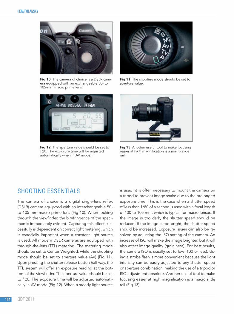
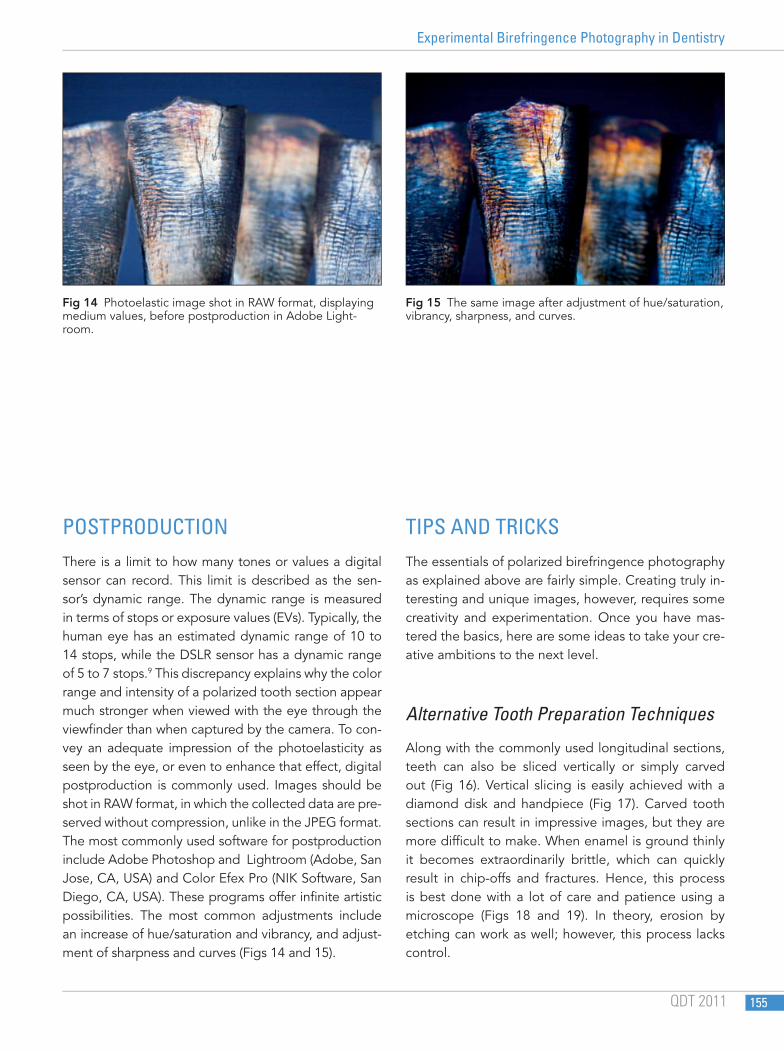
SHOOTING ESSENTIALSThe camera of choice is a digital single-lens reflex (DSLR) camera equipped with an interchangeable 50- to 105-mm macro prime lens (Fig 10). When looking through the viewfinder, the birefringence of the speci-men is immediately evident. Capturing this effect suc-cessfully is dependent on correct light metering, which is especially important when a constant light source is used. All modern DSLR cameras are equipped with through-the-lens (TTL) metering. The metering mode should be set to Center Weighted, while the shooting mode should be set to aperture value (AV) (Fig 11). Upon pressing the shutter release button half way, the TTL system will offer an exposure reading at the bot-tom of the viewfinder. The aperture value should be set to f 20. The exposure time will be adjusted automati-cally in AV mode (Fig 12). When a steady light source
is used, it is often necessary to mount the camera on a tripod to prevent image shake due to the prolonged exposure time. This is the case when a shutter speed of less than 1/80 of a second is used with a focal length of 100 to 105 mm, which is typical for macro lenses. If the image is too dark, the shutter speed should be reduced; if the image is too bright, the shutter speed should be increased. Exposure issues can also be re-solved by adjusting the ISO setting of the camera. An increase of ISO will make the image brighter, but it will also affect image quality (graininess). For best results, the camera ISO is usually set to low (100 or less). Us-ing a strobe flash is more convenient because the light intensity can be easily adjusted to any shutter speed or aperture combination, making the use of a tripod or ISO adjustment obsolete. Another useful tool to make focusing easier at high magnification is a macro slide rail (Fig 13).
Fig 10 The camera of choice is a DSLR cam-era equipped with an exchangeable 50- to 105-mm macro prime lens.
Fig 12 The aperture value should be set to f 20. The exposure time will be adjusted automatically when in AV mode.
Fig 11 The shooting mode should be set to aperture value.
Fig 13 Another useful tool to make focusing easier at high magnification is a macro slide rail.
HEIN.indd 154 5/3/11 10:04 AM
Experimental Birefringence Photography in Dentistry
QDT 2011 155
POSTPRODUCTIONThere is a limit to how many tones or values a digital sensor can record. This limit is described as the sen-sor’s dynamic range. The dynamic range is measured in terms of stops or exposure values (EVs). Typically, the human eye has an estimated dynamic range of 10 to 14 stops, while the DSLR sensor has a dynamic range of 5 to 7 stops.9 This discrepancy explains why the color range and intensity of a polarized tooth section appear much stronger when viewed with the eye through the viewfinder than when captured by the camera. To con-vey an adequate impression of the photoelasticity as seen by the eye, or even to enhance that effect, digital postproduction is commonly used. Images should be shot in RAW format, in which the collected data are pre-served without compression, unlike in the JPEG format. The most commonly used software for postproduction include Adobe Photoshop and Lightroom (Adobe, San Jose, CA, USA) and Color Efex Pro (NIK Software, San Diego, CA, USA). These programs offer infinite artistic possibilities. The most common adjustments include an increase of hue/saturation and vibrancy, and adjust-ment of sharpness and curves (Figs 14 and 15).
TIPS AND TRICKSThe essentials of polarized birefringence photography as explained above are fairly simple. Creating truly in-teresting and unique images, however, requires some creativity and experimentation. Once you have mas-tered the basics, here are some ideas to take your cre-ative ambitions to the next level.
Alternative Tooth Preparation Techniques
Along with the commonly used longitudinal sections, teeth can also be sliced vertically or simply carved out (Fig 16). Vertical slicing is easily achieved with a diamond disk and handpiece (Fig 17). Carved tooth sections can result in impressive images, but they are more difficult to make. When enamel is ground thinly it becomes extraordinarily brittle, which can quickly result in chip-offs and fractures. Hence, this process is best done with a lot of care and patience using a microscope (Figs 18 and 19). In theory, erosion by etching can work as well; however, this process lacks control.
Fig 14 Photoelastic image shot in RAW format, displaying medium values, before postproduction in Adobe Light-room.
Fig 15 The same image after adjustment of hue/saturation, vibrancy, sharpness, and curves.
HEIN.indd 155 5/3/11 10:04 AM

HEIN/POLANSKY
QDT 2011 156
18
16
17 19
Fig 16 Along with longitudinal sections, teeth can also be sliced vertically or simply carved out.
Fig 17 Vertical slicing is easily achieved with a diamond disk and handpiece.
Figs 18 and 19 Carved tooth sec-tions can result in impressive shots but are more difficult to make.
HEIN.indd 156 5/3/11 10:04 AM

Experimental Birefringence Photography in Dentistry
QDT 2011 157
Image Composition
Once useful samples have been produced, they must be arranged for shooting. This is largely an intuitive process. However, certain guidelines derived from other artistic fields can be useful. For example, figure-ground theory states that the empty space resulting from placing figures in a given arrangement should be considered as carefully as the figures themselves (Figs 20 and 21).10 This concept ties in with the Law of Präg-nanz, which describes the mind’s tendency to interpret ambiguous images as simple and complete, versus complex and incomplete.11 The vertical slices in Fig 17, for example, were arranged to take on the appear-
ance of tree trunks. Another major source of advice on figure arrangement is the work of Kandinsky.12 Once a number of good images have been gathered, an ob-ject can be separated from the original background using the quick selection tool in Photoshop. This al-lows for infinite arrangement possibilities. The most commonly applied methods include use of graduated backgrounds, lens flare, reflections, and opacity (Figs 22 and 23).
Altering the birefringenceA circular polarizing filter consists of the linear polarizer and a quarter wave plate. The latter is cemented to the back of the linear polarizer with a one-fourth orientation
20
22
21
23
Figs 20 and 21 Image composition is largely an intuitive process. However, figure-ground theory states that the empty space resulting from placing figures in a given arrangement should be considered as carefully as the figures themselves.
Fig 22 and 23 Objects can be separated from the original background using the quick selection tool in Photoshop. This allows for infinite arrangement possibilities.
HEIN.indd 157 5/3/11 10:04 AM

HEIN/POLANSKY
QDT 2011 158
25
so that the light emerging from the quarter wave plate is circularly polarized. Birefringence of the tooth section can be altered by adding more circular polarizing filters at both ends of the polariscope. This results in two side effects: a color shift by one order (eg, from blue primary to red primary) and a much darker image. However, this added darkness can be easily compensated for through appropriate aperture and shutter speed settings or an increase of ISO (Figs 24 and 25).
High dynamic range As mentioned previously, a standard, small-format DSLR sensor does not yield enough dynamic range to truly capture an image as it is perceived by the human eye. However, there are two ways of overcoming this limitation. The first is by shifting from a standard DSLR to a medium-format camera (eg, Phase One, Melville, New York, USA), which is equipped with a much larger charge-coupled device image sensor (53.9 × 40.4 mm) that can yield a dynamic range close to that of the hu-
man eye as well as a high resolution (60.5 MP). This re-sults in stunning image clarity and noticeably increased contrast range. Unfortunately, such camera systems are extremely expensive. A much more affordable way to achieve similar results is by using high dynamic range (HDR) technology, which offers a wide range of bright-ness values. HDR photography is the process of taking several pictures of a subject at various exposure levels, then merging the images into one file to maximize the dynamic range of the captured object. Each image that contributes to the final HDR photograph provides im-portant information about the subject; underexposed images capture highlight detail, and the overexposed images capture shadow detail (Fig 26). The merging process creates a 32-bit file that is capable of holding the full dynamic range of the subject (Fig 27).13 Various software programs can be used for the merging and tone-mapping process (eg, Photomatix Pro, HDR Soft, Sarl, Montpellier, France). Experimenting with this tech-nology can produce interesting results (Fig 28).
24
Figs 24 and 25 Birefringence of the tooth section can be shifted by adding a second circular polarizing filter to both ends of the polariscope. This results in a color shift by one order (eg, from blue primary to red primary).
HEIN.indd 158 5/3/11 10:04 AM

Experimental Birefringence Photography in Dentistry
QDT 2011 159
26
27
28
Figs 26 and 27 HDR photography is the process of taking several pictures of an object at various exposure levels, then merging the images into one file to maximize the dynamic range of the captured subject. The merging process creates a 32-bit file that is capable of holding the full dynamic range of the object.
Fig 28 Various software programs can be used for the merging and tone-mapping process. Experimenting with this technology can produce interesting results.
HEIN.indd 159 5/3/11 10:04 AM

HEIN/POLANSKY
QDT 2011 160
LCD polarizationA liquid crystal display (LCD) screen provides a ready-made source of polarized light. The screen itself can be used as the background polarizing material. In LCD screens, the polarizing filter is the last object that the light from the back of the display must travel through.14 The LCD screen therefore behaves as a very good source of polarized light. The first step in making the LCD screen a useful and uniform source of polar-
ized light is to give the screen a uniform brightness or tone across its entire surface, preferably white. There are various ways to achieve this. Creating an image file that consists of nothing but white is one way, as is choosing a screensaver that consists of a light tone or white background. The LCD screen practically be-comes a very large polarizing filter, allowing for larger and more elaborate compositions (Figs 29 and 30).
29
30
Figs 29 and 30 An LCD screen can practically become a very large polarizer, making the use of two circular polar-izing filters obsolete. The size of most LCD screens also allows for larger and more elaborate compositions.
HEIN.indd 160 5/3/11 10:04 AM

Experimental Birefringence Photography in Dentistry
QDT 2011 161
CONCLUSIONSThe birefringence images described in this article may be used to demonstrate the sheer difference between human teeth and dental ceramics. However, without rigorous scientific standardization and the use of a genuine polarized microscope, birefringence images of extracted/sliced teeth made in-house have limited scientific value. Nevertheless, from a purely artistic point of view, taking and collecting such images is a great source of inspiration. Using the methods de-scribed in this article, the enthusiast can flourish while exploring the beauty of the optical properties of hu-man teeth.
ACKNOWLEDGMENTSThe authors thank Dr Wolfgang Bengel for his willingness to share his detailed knowledge on how to create and enhance birefringence images. Thanks also to Mrs Christine Amrell for her inspiring ideas and her help with image selection. Without you, this would not have been possible.
REFERENCES 1. Sieber C. Illumination in den Frontzähnen. Quintessenz Zahn-
tech 1989;15:913–924. 2. Sieber C. Im Lichte der Natur. Quintessenz Zahntech 1991;17:
1301–1314. 3. Valentin G. Die Untersuchung der Pflanzen und Tiergewebe im
Polarisierten Licht. Leipzig, Germany: Engelman, 1861. 4. Kirk EC. Discussion of the observation of ground tooth sections
in polarized light. Dental Cosmos 1903;45:345. 5. Strainoptic. Fundamentals of Photoelasticity. http://www.strain-
optic.com/page.asp?page_id=87. Accessed June 2010. 6. Hajto J. Anteriores—Natuerlich Schoene Frontzaehne, vol 1.
Fuchstal: Teamwork Media, 2006:317–319 7. Logitech. Tooth Thin Section Preparation. http://www.fas.har-
vard.edu/~bioanth/tanya_smith/pdf/Thin_Section_Prep.pdf. Accessed June 2010
8. Bengel W. Mastering Digital Dental Photography. Chicago: Quintessence, 2006.
9. Eastway P. What is the difference? Better Photography 2010;6: 61–62.
10. Frederick M. 101 Things I Learned in Architecture School. Cam-bridge, MA: MIT Press, 2007:3–4.
11. Lidwell W, Holden K, Butler J. Universal Principles of Design. Beverly, MA: Rockport, 2003:120–121.
12. Kandinsky W. Point and Line to Plane. Mineola, NY: Dover, 1979.13. McCollough F. High Dynamic Range Digital Photography. Ashe-
ville, NC: Lark Books, 2008. 14. Wikipedia. Liquid Crystal Display. http://en.wikipedia.org/wiki/
Liquid_crystal_display. Accessed August 2010.
HEIN.indd 161 5/3/11 10:04 AM

Copyright of Quintessence of Dental Technology (QDT) is the property of Quintessence Publishing Company
Inc. and its content may not be copied or emailed to multiple sites or posted to a listserv without the copyright
holder's express written permission. However, users may print, download, or email articles for individual use.