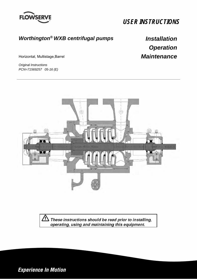
USER INSTRUCTIONS
Worthington® WXB centrifugal pumps Installation Operation
Maintenance Horizontal, Multistage,Barrel
Original Instructions PCN=71569257 05-16 (E)
WXB USER INSTRUCTIONS ENGLISH – 05/16
Page 2 von 52
CONTENTS PAGE 1.0 INTRODUCTION AND SAFETY ......................... 3
1.1 GENERAL ................................................................. 3 1.2 CE MARKING AND APPROVALS ................................ 3 1.3 DISCLAIMER ............................................................. 3 1.4 COPYRIGHT ............................................................. 3 1.5 DUTY CONDITIONS ................................................... 3 1.6 SAFETY .................................................................... 4 1.7 WARNING LABEL ...................................................... 8 1.8 SPECIFIC MACHINE PERFORMANCE ......................... 9 1.9 NOISE LEVEL ............................................................ 9 1.10 CE CERTIFICATION .............................................. 11
2.0 TRANSPORT AND STORAGE ......................... 12
2.1 CONSIGNMENT RECEIPT AND UNPACKING ............. 12 2.2 HANDLING .............................................................. 12 2.3 LIFTING .................................................................. 12 2.4 STORAGE ............................................................... 13 2.5 RECYCLING AND END OF PRODUCT LIFE ............... 13
3.0 DESCRIPTION .................................................. 13
3.1 CONFIGURATION .................................................... 13 3.2 NOMENCLATURE .................................................... 13 3.3 DESIGN OF MAJOR PARTS ..................................... 13 3.4 PERFORMANCE AND OPERATING LIMITS ............... 14
4.0 INSTALLATION ................................................ 14
4.1 LOCATION .............................................................. 14 4.2 PART ASSEMBLIES ................................................ 14 4.3 FOUNDATION ......................................................... 14 4.4 INITIAL ALIGNMENT ................................................. 14 4.5 PIPING .................................................................... 15 4.6 ELECTRICAL CONNECTIONS................................... 17 4.7 FINAL SHAFT ALIGNMENT CHECK ........................... 17
5.0 COMMISSIONING START-UP, OPERATION AND SHUTDOWN ................................................... 17
5.1 PRECOMMISSIONING PROCEDURE ........................ 17 5.2 PUMP LUBRICANTS ................................................ 18 5.3 IMPELLER CLEARANCE ........................................... 25 5.4 DIRECTION OF ROTATION ...................................... 25 5.5 GUARDING ............................................................. 25 5.6 PRIMING AND AUXILIARY SUPPLIES ....................... 25 5.7 STARTING THE PUMP ............................................. 25 5.8 OPERATION ............................................................ 26 5.9 STOPPING AND SHUTDOWN .................................. 26 5.10 HYDRAULIC, MECHANICAL AND ELECTRICAL DUTY ..................................................................................... 26
6.0 MAINTENANCE ................................................ 26
6.1 GENERAL ............................................................... 26 6.2 MAINTENANCE SCHEDULE ..................................... 27 6.3 SPARE PARTS ........................................................ 28 6.4 RECOMMENDED SPARES ....................................... 28 6.5 TIGHTENING TORQUE & TIGHTENING SEQUENCE .. 29 6.6 SETTING IMPELLER CLEARANCE ............................ 31 6.7 DISASSEMBLY ........................................................ 31 6.8 EXAMINATION OF PARTS ........................................ 33
6.9 ASSEMBLY ............................................................. 33 7.0 API DESIGN ...................................................... 36
7.1 GENERAL ............................................................... 36 7.2 MAINTENANCE SCHEDULE ..................................... 36 7.3 SPARE PARTS ........................................................ 37 7.4 RECOMMENDED SPARES ....................................... 38 7.5 TIGHTENING TORQUE & TIGHTENING SEQUENCE.. 38 7.6 SETTING IMPELLER CLEARANCE ............................ 40 7.7 DISASSEMBLY ........................................................ 40 7.8 EXAMINATION OF PARTS ........................................ 42 7.9 ASSEMBLY ............................................................. 42
8.0 AUXILIARIES .................................................... 44
8.1 SEAL AND SEAL SYSTEMS ..................................... 44 8.2 CHANGING OF MECHANICAL SEAL ......................... 46
9.0 FAULTS; CAUSES AND REMEDIES .............. 47 10.0 CERTIFICATION ............................................. 49 11.0 OTHER RELEVANT DOCUMENTATION AND MANUALS............................................................... 49
11.1 SUPPLEMENTARY USER INSTRUCTIONS.............. 49 11.2 CHANGE NOTES ................................................... 49 11.3 ADDITIONAL SOURCES OF INFORMATION ............ 49 11.4 ABBREVIATIONS .................................................. 50
WXB USER INSTRUCTIONS ENGLISH – 05/16
Page 3 von 52
1.0 INTRODUCTION AND SAFETY
1.1 General
These Instructions must always be kept close to product's operating location or directly with the product. Flowserve's products are designed, developed and manufactured with state-of-the-art technologies in modern facilities. The unit is produced with great care and commitment to continuous quality control, utilising sophisticated quality techniques, and safety requirements. Flowserve is committed to continuous quality improvement and being at service for any further information about the product in its installation and operation or about its support products, repair and diagnostic services. These instructions are intended to facilitate familiarization with the product and its permitted use. Operating the product in compliance with these instructions is important to help ensure reliability in service and avoid risks. The instructions may not take into account local regulations; ensure such regulations are observed by all, including those installing the product. Always coordinate repair activity with operations personnel, and follow all plant safety requirements and applicable safety and health laws/regulations.
These instructions must be read prior to installing, operating, using and maintaining the equipment in any region worldwide. The equipment must not be put into service until all the conditions relating to safety, noted in the instructions, have been met. Failure to follow and apply the present user instructions is considered to be misuse. Personal injury, product damage, delay or failure caused by misuse are not covered by the Flowserve warranty.
1.2 CE marking and approvals It is a legal requirement that machinery and equipment put into service within certain regions of the world shall conform with the applicable CE Marking Directives covering Machinery and, where applicable, Low Voltage Equipment, Electromagnetic Compatibility (EMC), Pressure Equipment Directive (PED) and Equipment for Potentially Explosive Atmospheres (ATEX). Where applicable the Directives, and any additional Approvals, cover important safety aspects relating to machinery and equipment and the satisfactory provision of technical documents and safety instructions. Where applicable this document
incorporates information relevant to these Directives. To establish Approvals and if the product itself is CE Marked check the serial number plate and the Certification.
1.3 Disclaimer Information in these User Instructions is believed to be reliable. In spite of all the efforts of Flowserve Corporation to provide sound and all necessary information the content of this manual may appear insufficient and is not guaranteed by Flowserve as to its completeness or accuracy. Flowserve manufactures products to exacting International Quality Management System Standards as certified and audited by external Quality Assurance organisations. Genuine parts and accessories have been designed, tested and incorporated into the products to help ensure their continued product quality and performance in use. As Flowserve cannot test parts and accessories sourced from other vendors the incorrect incorporation of such parts and accessories may adversely affect the performance and safety features of the products. The failure to properly select, install or use authorised Flowserve parts and accessories is considered to be misuse. Damage or failure caused by misuse is not covered by Flowserve's warranty. In addition, any modification of Flowserve products or removal of original components may impair the safety of these products in their use.
1.4 Copyright All rights reserved. No part of these instructions may be reproduced, stored in a retrieval system or transmitted in any form or by any means without prior permission of Flowserve.
1.5 Duty conditions This product has been selected to meet the specifications of your purchaser order. The acknowledgement of these conditions has been sent separately to the Purchaser. A copy should be kept with these instructions.
The product must not be operated beyond the parameters specified for the application. If there is any doubt as to the suitability of the product for the application intended, contact Flowserve for advice, quoting the serial number. If the conditions of service on your purchase order are going to be changed (for example liquid pumped, temperature or duty) it is requested that the user seeks Flowserve´s written agreement before start up.Safety
WXB USER INSTRUCTIONS ENGLISH – 05/16
Page 4 von 52
1.6 Safety
1.6.1 Summary of safety markings These user instructions contain specific safety markings where non-observance of an instruction would cause hazards. The specific safety markings are:
This symbol indicates electrical safety instructions where non-compliance will involve a high risk to personal safety or the loss of life.
This symbol indicates safety instructions where non-compliance would affect personal safety and could result in loss of life.
This symbol indicates "hazardous and toxic fluid" safety instructions where non-compliance would affect personal safety and could result in loss of life.
This symbol indicates safety instructions where non-compliance will involve some risk to safe operation and personal safety and would damage the equipment or property.
This symbol indicates "strong magnetic field" safety instructions where non-compliance would affect personal safety, pacemakers, instruments or stored data sensitive to magnetic fields.
This symbol indicates explosive atmosphere marking according to ATEX. It is used in safety instructions where non-compliance in the hazardous area would cause the risk of an explosion.
This symbol is used in safety instructions to remind not to rub non-metallic surfaces with a dry cloth; ensure the cloth is damp. It is used in safety instructions where non-compliance in the hazardous area would cause the risk of an explosion.
The sign is not a safety symbol but indicates an important instruction in the assembly process.
This symbol indicates potential risks connected with extremely high temperatures.
This symbol indicates potential risks connected with extremely low temperatures.
1.6.2 Personnel qualification and training All personnel involved in the operation, installation, inspection and maintenance of the unit must be qualified to carry out the work involved. If the personnel in question do not already possess the necessary knowledge and skill, appropriate training and instruction must be provided. If required the operator may commission the manufacturer / supplier to provide applicable training. Always co-ordinate repair activity with operations and health and safety personnel, and follow all plant safety requirements and applicable safety and health laws/regulations.
1.6.3 Safety action This is a summary of conditions and actions to help prevent injury to personnel and damage to the environment and to equipment.
PREVENT EXCESSIVE EXTERNAL PIPE LOAD Do not use pump as a support for piping. Do not mount expansion joints so that their force, due to internal pressure, acts on the pump flange.
ONLY CHECK DIRECTION OF MOTOR ROTATION WITH COUPLING ELEMENT/ PINS REMOVED Starting in reverse direction of rotation will damage the pump.
ENSURE CORRECT LUBRICATION (See section 5 Commissioning, startup, operation and shutdown.)
START THE PUMP WITH OUTLET VALVE PART OPENED (Unless otherwise instructed at a specific point in the user instructions.) This is recommended to avoid the risk of overloading and damaging the pump motor at full or zero flow. Pumps may be started with the valve further open only on installations where this situation cannot occur. Pump outlet valve shall be adjusted to comply with the duty following the run-up process (See section 5 Commisioning, startup, operation and shutdown).
START THE PUMP WITH OUTLET VALVE FULLY OPEN This is recommended to avoid the risk of overloading and damaging the pump motor where greater power is taken at low or shut off flow. Pump outlet valve shall be adjusted to comply with the duty following the run-up process (See section 5 Commisioning, startup, operation and shutdown).
WXB USER INSTRUCTIONS ENGLISH – 05/16
Page 5 von 52
NEVER RUN THE PUMP DRY
BALANCE LINE MUST BE OPEN AT ANY TIME. (Except maintenance work)
INLET VALVES TO BE FULLY OPEN WHEN PUMP IS RUNNING Running the pump at zero flow or below the recommended minimum flow continuously will cause damage to the seal.
DO NOT RUN THE PUMP AT ABNORMALLY HIGH OR LOW FLOW RATES Operating at a flow rate higher than normal or at a flow rate with no back pressure on the pump may overload the motor and cause cavitation. Low flow rates may cause a reduction in pump/bearing life, overheating of the pump, instability and cavitation/vibration.
When ambient temperatures are likely to drop below freezing point, the pump and any cooling and flushing arrangements must be drained or otherwise protected.
HANDLING COMPONENTS Many precision parts have sharp corners and the wearing of appropriate safety gloves and equipment is required when handling these components. To lift heavy pieces above 25 kg (55 lbs) use a crane corresponding to the mass and in accordance with current local regulations.
NEVER DO MAINTENANCE WORK WHILST THE UNIT IS CONNECTED TO POWER
HAZARDOUS LIQUIDS When the pump is handling hazardous liquids care must be taken to avoid exposure to the liquid by appropriate siting of the pump, limiting personnel access and by operator training. If the liquid is flammable and/or explosive strict safety procedures must be applied. Gland Packing must not be used when pumping hazardous liquids.
DRAIN PUMP AND ISOLATE PIPEWORK BEFORE DISMANTLING THE PUMP The appropriate safety precautions should be taken where the pumped liquids are hazardous.
FLUORO-ELASTOMERS (When fitted) When a pump has experienced temperatures over 250 °C (482 ºF), partial decomposition of fluoro-
elastomers (example: Viton) will occur. In this condition these are extremely dangerous and skin contact must be avoided.
GUARDS MUST NOT BE REMOVED WHILE PUMP IS OPERATIONAL
THERMAL SHOCK Rapid changes in the temperature of the liquid within the pump can cause thermal shock, which can result in damage or breakage of components and should be avoided.
NEVER APPLY HEAT TO REMOVE IMPELLER Trapped lubricant or vapour could cause an explosion.
HOT AND COLD PARTS If hot or freezing components or auxiliary heating supplies can present a danger to operators, they must be shielded to avoid accidental contact. If complete protection is not possible, the machine access must be limited to maintenance staff only. Note: bearing housings must not be insulated and drive motors and bearings may be hot. If the temperature is greater than 68 °C (155 °F) or below 5 °C (41 °F) in a restricted zone, or exceeds local regulations, action as above shall be taken.
1.6.4 Products used in potentially explosive atmospheres
Measures are required to: • Avoid excess temperature • Prevent build up of explosive mixtures • Prevent the generation of sparks • Prevent leakages • Maintain the pump to avoid hazard The following instructions for pumps and pump units when installed in potentially explosive atmospheres must be followed to help ensure explosion protection. Both electrical and non-electrical equipment must meet the requirements of European Directive 94/9/EC.
1.6.4.1 Scope of compliance
Use equipment only in the zone for which it is appropriate. Always check that the driver, drive coupling assembly, seal and pump equipment are suitably rated and/or certified for the classification of the specific atmosphere in which they are to be installed.
WXB USER INSTRUCTIONS ENGLISH – 05/16
Page 6 von 52
Where Flowserve has supplied only the bare shaft pump, the Ex rating applies only to the pump. The party responsible for assembling the pump set shall select the coupling, driver and any additional equipment, with the necessary CE Certificate/ Declaration of Conformity establishing it is suitable for the area in which it is to be installed. The output from a variable frequency drive (VFD) can cause additional heating affects in the motor and so, for pump sets with a VFD, the ATEX Certification for the motor must state that it covers the situation where electrical supply is from the VFD. This is particular requirement still applies even if the VFD is in a safe area.
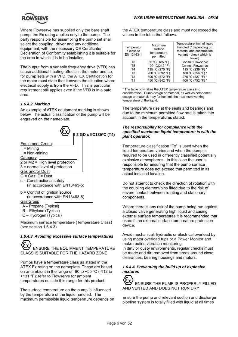
1.6.4.2 Marking An example of ATEX equipment marking is shown below. The actual classification of the pump will be engraved on the nameplate.
II 2 GD c IIC135ºC (T4) Equipment Group I = Mining II = Non-mining Category 2 or M2 = High level protection 3 = normal level of protection Gas and/or Dust G = Gas; D= Dust c = Constructional safety (in accordance with EN13463-5)
b = Control of ignition source (in accordance with EN13463-6) Gas Group IIA – Propane (Typical) IIB – Ethylene (Typical) IIC – Hydrogen (Typical)
Maximum surface temperature (Temperature Class) (see section 1.6.4.3)
1.6.4.3 Avoiding excessive surface temperatures
ENSURE THE EQUIPMENT TEMPERATURE CLASS IS SUITABLE FOR THE HAZARD ZONE Pumps have a temperature class as stated in the ATEX Ex rating on the nameplate. These are based on an ambient in the range of -80 to +55 ºC (-112 to +131 ºF); refer to Flowserve for ambient temperatures outside this range for this product. The surface temperature on the pump is influenced by the temperature of the liquid handled. The maximum permissible liquid temperature depends on
the ATEX temperature class and must not exceed the values in the table that follows.
Temperature class to
EN 13463-1
Maximum surface
temperature permitted
Temperature limit of liquid handled (* depending on material and construction variant - check which is
lower) T6 T5 T4 T3 T2 T1
85 °C (185 °F) 100 °C(212 °F) 135 °C (275 °F) 200 °C (392 °F) 300 °C (572 °F) 450 °C (842 °F)
Consult Flowserve Consult Flowserve 115 °C (239 °F) * 180 °C (356 °F) * 275 °C (527 °F) * 400 °C (752 °F) *
* The table only takes the ATEX temperature class into consideration. Pump design or material, as well as component design or material, may further limit the maximum working temperature of the liquid. The temperature rise at the seals and bearings and due to the minimum permitted flow rate is taken into account in the temperatures stated. The responsibility for compliance with the specified maximum liquid temperature is with the plant operator. Temperature classification “Tx” is used when the liquid temperature varies and when the pump is required to be used in differently classified potentially explosive atmospheres. In this case the user is responsible for ensuring that the pump surface temperature does not exceed that permitted in its actual installed location. Do not attempt to check the direction of rotation with the coupling element/pins fitted due to the risk of severe contact between rotating and stationary components. Where there is any risk of the pump being run against a closed valve generating high liquid and casing external surface temperatures it is recommended that users fit an external surface temperature protection device. Avoid mechanical, hydraulic or electrical overload by using motor overload trips or a Power Monitor and make routine vibration monitoring. In dirty or dusty environments, regular checks must be made and dirt removed from areas around close clearances, bearing housings and motors.
1.6.4.4 Preventing the build up of explosive mixtures
ENSURE THE PUMP IS PROPERLY FILLED AND VENTED AND DOES NOT RUN DRY Ensure the pump and relevant suction and discharge pipeline system is totally filled with liquid at all times
WXB USER INSTRUCTIONS ENGLISH – 05/16
Page 7 von 52
during the pump operation, so that an explosive atmosphere is prevented. In addition it is essential to make sure that seal chambers, auxiliary shaft seal systems and any heating and cooling systems are properly filled. If the operation of the system cannot avoid this condition the fitting of an appropriate Dry Run protection device is recommended (eg liquid detection or a Power Monitor). To avoid potential hazards from fugitive emissions of vapour or gas to atmosphere the surrounding area must be well ventilated.
1.6.4.5 Preventing sparks
To prevent a potential hazard from mechanical contact the coupling guard must be non-sparking and anti-static. To avoid the potential hazard from random induced current generating a spark the earth contact on the baseplate must be used.
Avoid electrostatic charge: do not rub non-metallic surfaces with a dry cloth; ensure cloth is damp. The coupling must be selected to comply with 94/9/EC and correct alignment must be maintained.
1.6.4.6 Preventing leakage
The pump must only be used to handle liquids for which it has been approved to have the correct corrosion resistance. Avoid entrapment of liquid in the pump and associated piping due to closing of suction and discharge valves, which could cause dangerous excessive pressures to occur if there is heat input to the liquid. This can occur if the pump is stationary or running. Bursting of liquid containing parts due to freezing must be avoided by draining or protecting the pump and ancillary systems. Where there is the potential hazard of a loss of a seal barrier fluid or external flush, the fluid must be monitored. If leakage of liquid to atmosphere can result in a hazard, the installation of a liquid detection device is recommended.
1.6.4.7 Maintenance to the centrifugal pump to avoid the hazard
CORRECT MAINTENANCE IS REQUIRED TO AVOID POTENTIAL HAZARDS WHICH GIVE A RISK OF EXPLOSION The responsibility for compliance with maintenance instructions is with the plant operator. To avoid potential explosion hazards during maintenance, the tools, cleaning and painting materials used must not give rise to sparking or adversely affect the ambient conditions. Where there is a risk from such tools or materials, maintenance must be conducted in a safe area. It is recommended that a maintenance plan and schedule is adopted (see section 6, Maintenance).to include the following. a) Any auxiliary systems installed must be
monitored, if necessary, to ensure they function correctly.
b) Gland packings must be adjusted correctly to give visible leakage and concentric alignment of the gland follower to prevent excessive temperature of the packing or follower.
c) Check for any leaks from gaskets and seals. The correct functioning of the shaft seal must be checked regularly
d) Check bearing lubricant level, and if the hours run show a lubricant change is required.
e) Check that the duty condition is in the safe operating range for the pump.
f) Check vibration, noise level and surface temperature at the bearings to confirm satisfactory operation.
g) Check dirt and dust is removed from areas around close clearances, bearing housings and motors.
Check coupling alignment and re-align if necessary.
WXB USER INSTRUCTIONS ENGLISH – 05/16
Page 8 von 52
1.7 Warning label

WXB USER INSTRUCTIONS ENGLISH – 05/16
Page 9 von 52
1.8 Specific machine performance For performance parameters see section 1.5, Duty conditions. When the Contract requirement specifies these to be incorporated into user instructions these are included here. Where performance data has been supplied separately to the purchaser these should be obtained and retained with these user instructions if required.
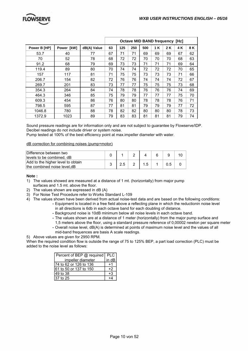
1.9 Noise level Attention must be given to the exposure of personnel to the noise, and local legislation will define when guidance to personnel on noise limitation is required, and when noise exposure reduction is mandatory. This is typically 80 to 85 dBA. The usual approach is to control the exposure time to the noise or to enclose the machine to reduce emitted sound. You may have already specified a limiting noise level when the equipment was ordered, however if no noise requirements were defined, then attention is drawn to the following table to give an indication of equipment noise level so that you can take the appropriate action in your plant. Pump noise level is dependent on a number of operational factors, flow rate, pipework design and acoustic characteristics of the building, and so the values given are subject to a 3 dBA tolerance and cannot be guaranteed. Similarly the motor noise assumed in the “pump and motor” noise is that typically expected from standard and high efficiency motors when on load directly driving the pump. Note that a motor driven by an inverter may show an increased noise at some speeds. If a pump unit only has been purchased for fitting with your own driver then the “pump only” noise levels in the table should be combined with the level for the driver obtained from the supplier. Consult Flowserve or a noise specialist if assistance is required in combining the values. It is recommended that where exposure approaches the prescribed limit, then site noise measurements should be made. The values are in sound pressure level LpA at 1 m (3.3 ft) from the machine, for “free field conditions over a reflecting plane”. For estimating sound power level LWA (re 1 pW) then add 14 dBA to the sound pressure value.
WXB USER INSTRUCTIONS ENGLISH – 05/16
Page 10 von 52
Power B [HP] Power [kW] dB(A) Value 63 125 250 500 1 K 2 K 4 K 8 K 53.7 40 77 67 71 71 69 69 69 67 62 70 52 78 68 72 72 70 70 70 68 63
91.2 68 79 69 73 73 71 71 71 69 64 119.4 89 80 70 74 74 72 72 72 70 65 157 117 81 71 75 75 73 73 73 71 66
206.7 154 82 72 76 76 74 74 74 72 67 269.7 201 83 73 77 77 75 75 75 73 68 354.3 264 84 74 78 78 76 76 76 74 69 464.3 346 85 75 79 79 77 77 77 75 70 609.3 454 86 76 80 80 78 78 78 76 71 798.5 595 87 77 81 81 79 79 79 77 72 1046.8 780 88 78 82 82 80 80 80 78 73 1372.9 1023 89 79 83 83 81 81 81 79 74
Sound pressure readings are for information only and are not subject to guarantee by Flowserve/IDP. Decibel readings do not include driver or system noise. Pump tested at 100% of the best efficiency point at max.impeller diameter with water.
dB correction for combining noises (pump+motor)
Add to the higher level to obtain the combined noise level,dB
Note : 1) The values showed are measured at a distance of 1 mt. (horizontally) from major pump surfaces and 1.5 mt. above the floor. 2) The values shown are expressed in dB (A) 3) For Noise Test Procedure refer to Works Standard L-109 4) The values shown have been derived from actual noise-test data and are based on the following conditions:
- Equipment is located in a free field above a reflecting plane in which the reductionin noise level in all directions is 6db in each octave band for each doubling of distance.
- Background noise is 10dB minimum below all noise levels in each octave band. - The values shown are at a distance of 1 meter (horizontally) from the major pump surface and
1,5 meters above the floor, using a standard pressure reference of 0,00002 newton per square meter. - Overall noise level, dB(A) is determined at points of maximum noise level and the values of all
mid-band frequences are basis A scale readings. 5) Above values are given for 2950 RPM. When the required condition flow is outside the range of 75 to 125% BEP, a part load correction (PLC) must be added to the noise level as follows:
Percent of BEP @ required impeller diameter
PLC in dB
74 to 62 or 126 to 136 +1 61 to 50 or 137 to 150 +2 49 to 38 +3 37 to 25 +4
1 0.5 0 3 2.5 2 1.5 levels to be combined, dB Difference between two
Octave MID BAND frequency [Hz]
0 1 2 4 6 9 10

WXB USER INSTRUCTIONS ENGLISH – 05/16
Page 11 von 52
1.10 CE certification
WXB USER INSTRUCTIONS ENGLISH – 05/16
Page 12 von 52
2.0 TRANSPORT AND STORAGE
2.1 Consignment receipt and unpacking Immediately after receipt of the equipment it must be checked against the delivery/ shipping documents for its completeness and that there has been no damage in transportation. Any shortage and or damage must be reported immediately to Flowserve and received in writing within one month of receipt of the equipment. Latter claims cannot be accepted. Check any create/boxes/wrappings for any accessories or spare parts which may be packed separately with the equipment or attached to side walls of the box or equipment. Each product has a unique serial number. Check that this number corresponds with that advised and always quote this number in correspondence as well as when ordering spare parts or further accessories.
2.2 Handling Boxes, crates, pallets or cartons may be unloaded using fork lift vehicles or slings dependent on their size and construction.
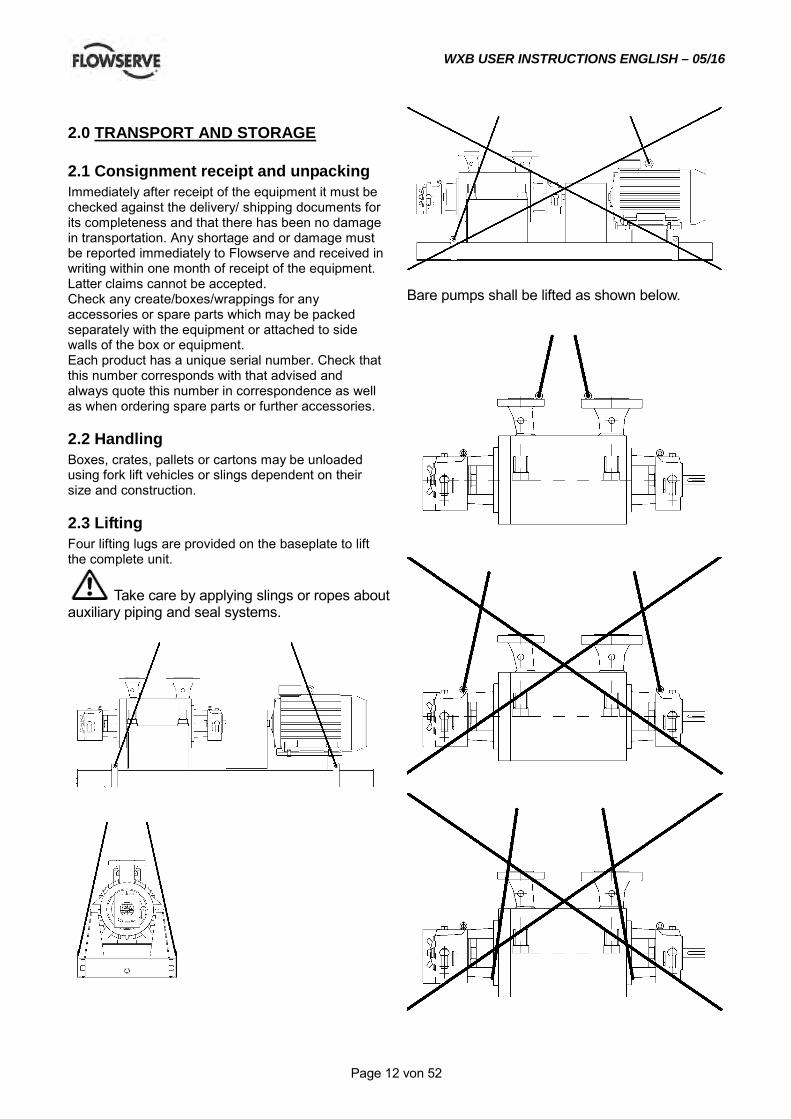
2.3 Lifting Four lifting lugs are provided on the baseplate to lift the complete unit.
Take care by applying slings or ropes about auxiliary piping and seal systems.
Bare pumps shall be lifted as shown below.
WXB USER INSTRUCTIONS ENGLISH – 05/16
Page 13 von 52
A crane must be used for all pump sets in excess of 25kg (55lb). Fully trained personnel must carry out lifting, in accordance with local regulations. The driver and pump weights are recorded on their respective nameplates.
2.4 Storage If the unit will not be put immediately into service, it should be stored in a dry room. To avoid any damage during the storage period, the influence of any low or high frequency vibration must be totally inhibited. If the pump is delivered sealed in a plastic-wrapper, it is of max. importance to avoid any damage of that wrapper, because this will protect the pump against humidity. Therefore it must be checked if this wrapper has become cracked and if so, the wrapper must be renewed.
2.4.1 Long period storage If the pump is delivered in a plastic bag, the preservations stands up for one year. If the storage period exceeds this time, the preservation must be checked and renewed. Also the air tight plastic bag must be changed. Moreover we recommend to order a Flowserve Service Engineer for checking the pump before the first start up.
2.5 Recycling and end of product life At the end of the service life of the product or its parts, the relevant materials and parts should be recycled or disposed of using an environmentally acceptable method and local regulations. If the product contains substances which are harmful to the environment, these should be removed and disposed of in accordance with current regulations. This also includes the liquids and or gases in the "seal system" or other utilities.
Make sure that hazardous substances are disposed of safety and that the correct personal protective equipment is used. The safety specifications must be in accordance with the current regulations at all times.
3.0 DESCRIPTION
3.1 Configuration The model WXB belongs to Flowserves family of barrel pumps. The pump line is based on a modular system, thus providing maximum design and operating flexibility. The maximum allowable working pressure range is from 100 bar for the smaller sizes up to 150 bar for the larger sizes. The pump is equipped with a balancing device for axial thrust compensation,
usually used for heavy boiler feed service and hydrocarbon service. It can be combined with an inducer for low NPSHA applications.
The sense of rotation of the pump is clockwise (CW), looking from the coupling to the shaft end of the pump.
3.2 Nomenclature Example: 3 WXB-10A8 – Ind. 3 Discharge nozzle in inch. B Barrel 10 max. impeller size in inch A type of hydraulics 8 no. of stages Ind Inducer
3.3 Design of major parts
3.3.1 Bearing housing Made of carbon steel. It is flanged to the pump casing and provides enough space for mechanical seals according to API 682.
3.3.2 Discharge and Suction head Both heads are designed for the maximum allowable working pressure. To avoid any distorsion due to thermal expansion, centerline mounting is obligatory.
3.3.3 Balance device To compensate the axial thrust a balancing device, consisting of a straight drum and a steped drum head is used. The step in the drum head separates the flow at the drum from the influence of the last stage impeller. This results in a smooth pressure distribution across the drum surface, which increases the rotordynamic stability and axial thrust compensation.
3.3.4 Hydraulics The hydraulics consists of three parts: • Impeller with wear rings • Multivaned diffuser with return vanes, for radial
load compensation • Channel ring, as internal pressure boundary and
cross over to next stage
WXB USER INSTRUCTIONS ENGLISH – 05/16
Page 14 von 52
3.3.5 Inducer All different impellers can be optionally equipped with an inducer for low NPSHA applications.
3.3.6 Barrel The barrel acts as pressure casing. The design allows that the pump internals can be pulled out fully assembled as complete hydraulic cartridge.
3.4 Performance and operating limits
In the interest of operator safety the unit must not be operated above the nameplate conditions. Such operation could result in unit failure causing injury to operating personnel. Consult instruction book for correct operation and maintenance of the pump and its supporting components.
4.0 INSTALLATION
Equipment operated in hazardous locations must comply with the relevant explosion protection regulations.
4.1 Location The pump should be located to allow room for access, ventilation, maintenance and inspection with ample headroom for lifting and should be as close as practicable to the supply of liquid to be pumped. Refer to the general arrangement drawing for the pump set.
4.2 Part Assemblies The pumps are delivered completely mounted and prealigned with the motor. Also the shaft seal is in the correct position. Final alignment after complete installation is necessary. If drivers and/or seal systems are delivered separately, follow the assembly procedure in section 6.8.
4.3 Foundation The foundation shall be located on a place that allows a minimum of pipe work and that is easily accessible for inspection during operation. According to the environment the foundation may consist of concrete or of steel. It must be rigid and heavy enough to absorb normal vibrations and shocks.
4.3.1 Horizontal alignment of the baseplate Horizontal alignment is done with levelling screws. Use a spirit level for correct horizontal alignment of the baseplate.
The max. misalignment is 0.5 mm/m baseplate length.
4.3.2 Steel foundation When the pump unit is mounted directly on structural steel frame, it shall be well supported by constructural beams. It is recommended to check the natural frequency of the steel frame, because it shall not coincide with the pump speed. The exact horizontal alignment is very important!
Ensure that the base plate is leveled horizontally to 0.5 mm/m. To avoid any distortion of put shims under the base plate before bolting it down to the steel frame. Welding of the base plate to the steel frame is not recommended because of possible distortion of the same.
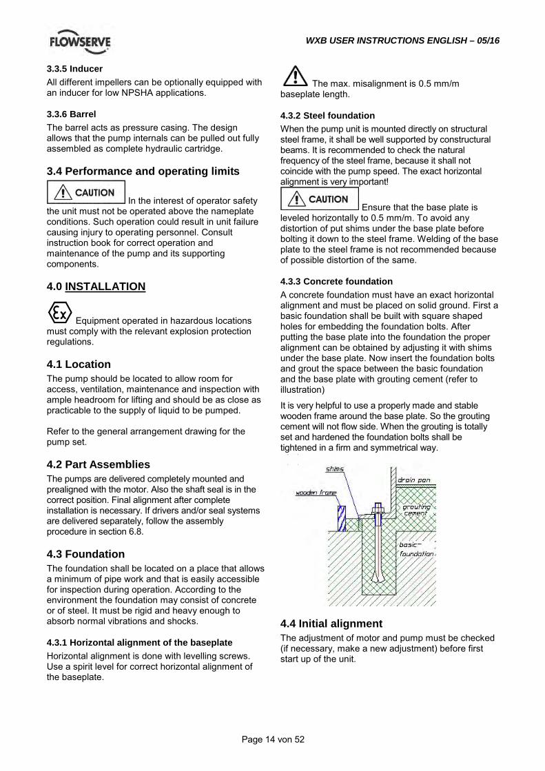
4.3.3 Concrete foundation A concrete foundation must have an exact horizontal alignment and must be placed on solid ground. First a basic foundation shall be built with square shaped holes for embedding the foundation bolts. After putting the base plate into the foundation the proper alignment can be obtained by adjusting it with shims under the base plate. Now insert the foundation bolts and grout the space between the basic foundation and the base plate with grouting cement (refer to illustration)
It is very helpful to use a properly made and stable wooden frame around the base plate. So the grouting cement will not flow side. When the grouting is totally set and hardened the foundation bolts shall be tightened in a firm and symmetrical way.
4.4 Initial alignment The adjustment of motor and pump must be checked (if necessary, make a new adjustment) before first start up of the unit.
WXB USER INSTRUCTIONS ENGLISH – 05/16
Page 15 von 52
Ensure pump and driver are isolated electrically and the half couplings are disconnected. Align the motor to the pump, not the pump to the motor. Alignment of the motor is achieved by using the adjustment screws.
4.4.1 Permissible misalignment limits at working temperature
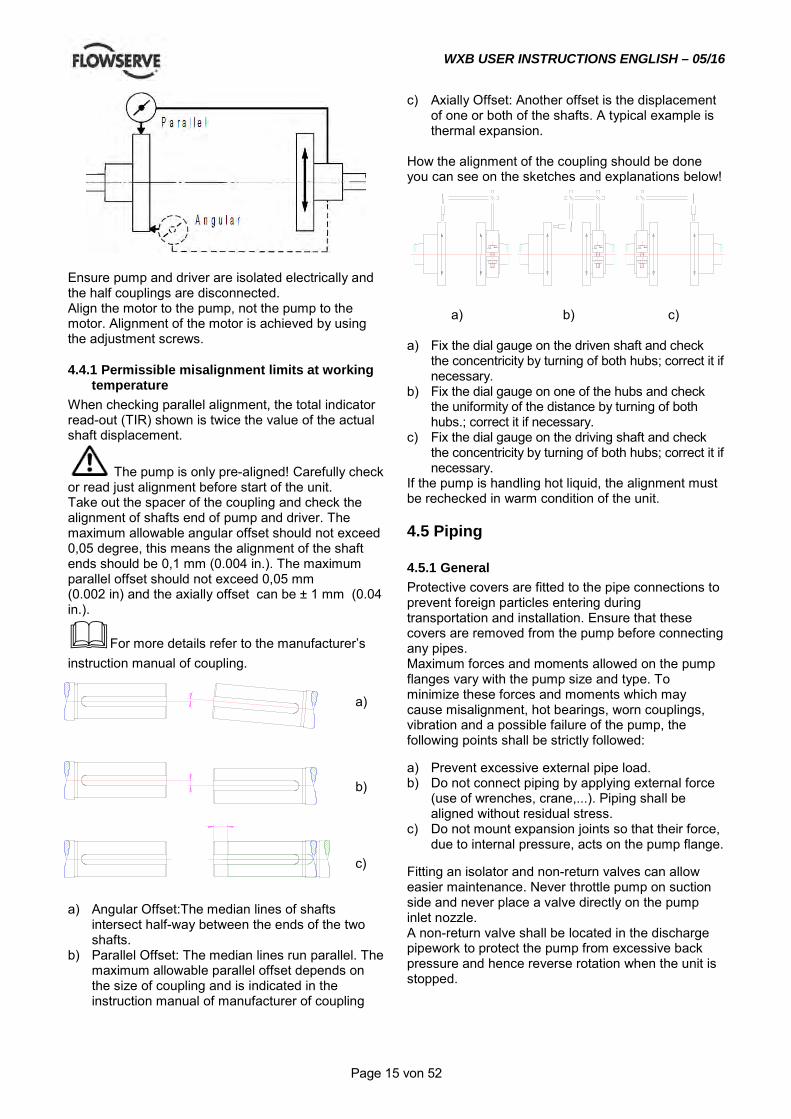
When checking parallel alignment, the total indicator read-out (TIR) shown is twice the value of the actual shaft displacement.
The pump is only pre-aligned! Carefully check or read just alignment before start of the unit. Take out the spacer of the coupling and check the alignment of shafts end of pump and driver. The maximum allowable angular offset should not exceed 0,05 degree, this means the alignment of the shaft ends should be 0,1 mm (0.004 in.). The maximum parallel offset should not exceed 0,05 mm (0.002 in) and the axially offset can be ± 1 mm (0.04 in.).
For more details refer to the manufacturer’s instruction manual of coupling.
a)
b) c)
a) Angular Offset:The median lines of shafts
intersect half-way between the ends of the two shafts.
b) Parallel Offset: The median lines run parallel. The maximum allowable parallel offset depends on the size of coupling and is indicated in the instruction manual of manufacturer of coupling
c) Axially Offset: Another offset is the displacement of one or both of the shafts. A typical example is thermal expansion.
How the alignment of the coupling should be done you can see on the sketches and explanations below!
a) b) c) a) Fix the dial gauge on the driven shaft and check
the concentricity by turning of both hubs; correct it if necessary.
b) Fix the dial gauge on one of the hubs and check the uniformity of the distance by turning of both hubs.; correct it if necessary.
c) Fix the dial gauge on the driving shaft and check the concentricity by turning of both hubs; correct it if necessary.
If the pump is handling hot liquid, the alignment must be rechecked in warm condition of the unit.
4.5 Piping
4.5.1 General Protective covers are fitted to the pipe connections to prevent foreign particles entering during transportation and installation. Ensure that these covers are removed from the pump before connecting any pipes. Maximum forces and moments allowed on the pump flanges vary with the pump size and type. To minimize these forces and moments which may cause misalignment, hot bearings, worn couplings, vibration and a possible failure of the pump, the following points shall be strictly followed: a) Prevent excessive external pipe load. b) Do not connect piping by applying external force
(use of wrenches, crane,...). Piping shall be aligned without residual stress.
c) Do not mount expansion joints so that their force, due to internal pressure, acts on the pump flange.
Fitting an isolator and non-return valves can allow easier maintenance. Never throttle pump on suction side and never place a valve directly on the pump inlet nozzle. A non-return valve shall be located in the discharge pipework to protect the pump from excessive back pressure and hence reverse rotation when the unit is stopped.
WXB USER INSTRUCTIONS ENGLISH – 05/16
Page 16 von 52
Piping and fittings shall be flushed before use. To avoid damages of the pump install a Y-strainer or a strainer of 40 mesh. Piping for corrosive liquids shall be arranged to allow pump flushing before removal of a unit.
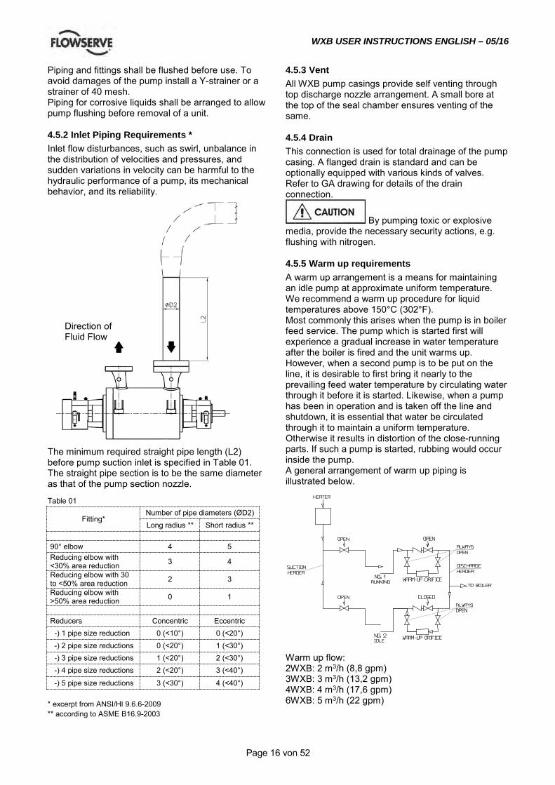
4.5.2 Inlet Piping Requirements * Inlet flow disturbances, such as swirl, unbalance in the distribution of velocities and pressures, and sudden variations in velocity can be harmful to the hydraulic performance of a pump, its mechanical behavior, and its reliability.
The minimum required straight pipe length (L2) before pump suction inlet is specified in Table 01. The straight pipe section is to be the same diameter as that of the pump section nozzle. Table 01
Fitting* Number of pipe diameters (ØD2) Long radius ** Short radius **
90° elbow 4 5 Reducing elbow with <30% area reduction 3 4
Reducing elbow with 30 to <50% area reduction 2 3
Reducing elbow with >50% area reduction 0 1
Reducers Concentric Eccentric -) 1 pipe size reduction 0 (<10°) 0 (<20°) -) 2 pipe size reductions 0 (<20°) 1 (<30°) -) 3 pipe size reductions 1 (<20°) 2 (<30°) -) 4 pipe size reductions 2 (<20°) 3 (<40°)
-) 5 pipe size reductions 3 (<30°) 4 (<40°) * excerpt from ANSI/HI 9.6.6-2009 ** according to ASME B16.9-2003
4.5.3 Vent All WXB pump casings provide self venting through top discharge nozzle arrangement. A small bore at the top of the seal chamber ensures venting of the same.
4.5.4 Drain This connection is used for total drainage of the pump casing. A flanged drain is standard and can be optionally equipped with various kinds of valves. Refer to GA drawing for details of the drain connection.
By pumping toxic or explosive media, provide the necessary security actions, e.g. flushing with nitrogen.
4.5.5 Warm up requirements A warm up arrangement is a means for maintaining an idle pump at approximate uniform temperature. We recommend a warm up procedure for liquid temperatures above 150°C (302°F). Most commonly this arises when the pump is in boiler feed service. The pump which is started first will experience a gradual increase in water temperature after the boiler is fired and the unit warms up. However, when a second pump is to be put on the line, it is desirable to first bring it nearly to the prevailing feed water temperature by circulating water through it before it is started. Likewise, when a pump has been in operation and is taken off the line and shutdown, it is essential that water be circulated through it to maintain a uniform temperature. Otherwise it results in distortion of the close-running parts. If such a pump is started, rubbing would occur inside the pump. A general arrangement of warm up piping is illustrated below.
Warm up flow: 2WXB: 2 m3/h (8,8 gpm) 3WXB: 3 m3/h (13,2 gpm) 4WXB: 4 m3/h (17,6 gpm) 6WXB: 5 m3/h (22 gpm)
Direction of Fluid Flow
WXB USER INSTRUCTIONS ENGLISH – 05/16
Page 17 von 52
4.5.6 Balancing line The pump must have a balancing line back to suction for proper axial thrust balancing. This could be a) an internal balancing line. This is usually used for
water services up to 80°C (176°F). b) a connection for an external balancing line. This
is usually used for hot water and hydrocarbon service.
Refer to GA drawing for type of balancing line.
4.5.6.1 Design guidelines for external balancing line The balancing line shall be led back to the suction vessel. The line must be open during operation to avoid damage of the equipment. The maximum back pressure created in the balance line, shall not exceed 2 bar (29 psi) above suction pressure. Therefore the balance line shall be designed for a pressure loss of max. 1 bar (14.5 psi). The following table gives the expected balance flow rates:
2 WXB 6 m³/h (26.4 gpm) 3WXB 8 m³/h (35.2 gpm) 4WXB 10 m³/h (44.4 gpm) 6WXB 11 m³/h (48.4 gpm)
These flowrates shall be used for the piping design. Flashing of the fluid in the balancing line shall be avoided, therefore the installation of an anti-flashing orifice at the end of the balancing line is recommended.
Design and manufacturing of the balance line is not within the responsibility of FPD.
4.6 Electrical connections
Electrical connections must be made by a qualified Electrician in accordance with the relevant local national and international regulations.
It is important to be aware of the EUROPEAN DIRECTIVE on hazardous areas where compliance with IEC60079-14 is an additional requirement for making electrical connections.
It is important to be aware of the EUROPEAN DIRECTIVE on electromagnetic compatibility when wiring up and installing equipment on site. Attention must be paid to ensure that the techniques used during wiring/installation do not increase electromagnetic emissions or decrease the electromagnetic immunity of the equipment, wiring or
any connected devices. If in any doubt contact Flowserve for advice.
The motor must be wired up in accordance with the motor manufacturer's instructions (normally supplied within the terminal box) including any temperature, earth leakage, current and other protective devices as appropriate. The identification nameplate should be checked to ensure the power supply is appropriate.
A device to provide emergency stopping must be fitted. If not supplied pre-wired to the pump unit the controller/starter electrical details will also be supplied within the controller/starter. For electrical details on pump sets with controllers see the separate wiring diagram.
See section 5.5, Direction of rotation before connecting the motor to the electrical supply.
4.7 Final shaft alignment check After connecting piping to the pump, rotate the shaft several times by hand to ensure there is no seizure and all parts are free. Recheck the coupling alignment, as previously described, to ensure no pipe strain. If pipe strain exists, correct piping.
5.0 COMMISSIONING START-UP, OPERATION AND SHUTDOWN
These operations must be carried out by fully qualified personnel.
5.1 Precommissioning procedure a) The bearing housing must be filled with the
indicated oil. Check also the oil level. b) The pump must be completely filled with liquid to
avoid running dry and to guarantee a correct performance of the pump.
c) During filling the pump shall reach the specified temperature, so pumps for hot liquids (T > 150 °C (302 °F)) shall be warmed up by preflushing.
d) Check the sense of rotation of the pump (Coupling spacer dismantled). Sense of rotation is clockwise viewed to the drive end of the pump.
e) The pump rotor and the shaft seal must be in correct axial position. Mounting plates of mechanical seal must be locked at the seal gland in open position. Drive-collar of the mechanical
WXB USER INSTRUCTIONS ENGLISH – 05/16
Page 18 von 52
seal sleeve must be tightend. f) Check the readiness of all auxiliary systems (seal
sys., lubrication sys.,...) for start up. g) All pipe work, including the internal and the
auxiliary pipe work, must be connected correctly and must be absolutely tight. Check the tightness of all connections of the auxiliary pipe work. The suction valve must be open, the discharge valve shall be closed.
The balance line must be opened prior to start up and locked open during operation.
h) Turn the pump by hand, if required with the help of a lever, to check the free rotation of the rotor. The rotor must turn uniformly and noiselessly. Some resistance may be felt due to friction in bearings and seals.
i) Check the readiness of the driver for start up. Refer to the manual of the driver (preheating for explosion proof E-motor).
5.2 Pump Lubricants
5.2.1 Lubrication The bearing housing shall be filled with proper lubricating oil prior to start up. If the pump will be started after a longer storage period, the bearing housing should be first flushed and cleaned with gasoline. It is not necessary to remove the preservation oil as this will mix up thoroughly with the lubrication oil. Lubrication is provided by the pumping effect of the rotating ball bearings. Maintaining the correct oil level (middle of the oil sight glass) ensures that the lower ball bearing is covered with oil. For recommended lubricating oils refer to the lubrication table 5.2.6
5.2.2 Oil change After first start up, the oil shall be changed after 200 service hours. Every further oil change shall take place after about 2000 service hours or at least every 6 month. To change the oil use the following procedure: a) Remove the reservoir (for some type of oilers you
must loose a fixing screw or lock nut, refer to section 5.2.3 Oil level).
b) Open the oil drain on the bearing housing to remove the oil.
c) Close the oil drain and fill in Oil through the oiler until the oil level reaches the bottom of the sight glass.
d) Fill the reservoir and put it quickly to the body of the oiler. Observe the level in the reservoir. It will decrease until the required oil level is reached (middle of the sight glass). Ensure that enough oil remains in the reservoir.
e) If necessary, the oil level can be adjusted by referring to section 5.2.3 Oil level.
5.2.3 Oil level The correct oil level is in the middle of the oil sight glass and shall be checked when pump is not in operation. Periodically check if the lubricating oil is mixed with any condensed water. Careful opening of the oil drain during a stop of the pump will show any water.
Use a spirit level to check the horizontal alignment of the bearing housing.
A too high oil level will result in higher bearing temperatures and therefore poorer lubrication.
5.2.4 Oil quality Oil used for lubrication should only be of high quality. The viscosity of the oil at working temperature must be at least 10 cSt. The pouring point of the oil must be in accordance with the lowest expected temperature of the bearing housing during a stop of the pump. For recommended lubricating oils refer to the lubrication table. Having selected the corresponding oil quality the actual oil temperature at the bearing housing must be checked after two service hours of the pump. Considering this measured oil temperature the actual viscosity must be determined by using the data sheet of the oil, to verify the minimum required viscosity of 10 cSt. Do not forget, the oil temperature in the bearing itself is about 10 °C (∆18 °F) higher than the oil temperature at the bearing housing. On the following table the oil viscosity is given at 40 °C (104 °F). Determining the correct lubricating oil one must take into consideration that all bearings will have higher temperatures during the first 20 service hours. In constant operation the bearing temperature will decrease about 10 °C (50 °F). The oil temperature shall be lower than 85 °C (185 °F) after this running-in time. The bearing outer race temperature should not exceed 95°C (204°F). If the temperature is higher, the reason may be a wrong oil quality, wrong oil level or overload of the pump because of excessive wear. If the humidity at the site is high, the roller bearings become easily rusty during stand still periods. To avoid that, we recommend to mix the lubricating oil with a corrosion inhibitor contact your lubrication oil supplier for proper additives inhibitors.
5.2.5 Oil quantity Bearing size is shown on the name plate of the pump, and with this the correct thrust and line bearing frame can be selected according to the following table.

WXB USER INSTRUCTIONS ENGLISH – 05/16
Page 19 von 52
2WXB
Bearing housing [3200.1]
with Oiler [3855] without Oiler [3855]
0,42 l (14.2 Fl.oz.) 0,3 l (10.1 Fl.oz.)
Bearing housing [3200.2]
with Oiler [3855] without Oiler [3855]
0,37 l (12.5 Fl.oz.) 0,25 l (8.4 Fl.oz.)
3WXB
Bearing housing [3200.1]
with Oiler [3855] without Oiler [3855]
0,82 l (27.7 Fl.oz.) 0,7 l (23.6 Fl.oz.)
Bearing housing [3200.2]
with Oiler [3855] without Oiler [3855]
0,77 l (26 Fl.oz.) 0,65 l (22 Fl.oz.)
4WXB
or
6WXB
Bearing housing [3200.1]
with Oiler [3855] without Oiler [3855]
1,12 l (37.9 Fl.oz.) 1 l (33.8 Fl.oz.)
Bearing housing [3200.2]
with Oiler [3855] without Oiler [3855]
0,97 l (32.8 Fl.oz.) 0,85 l (28.7 Fl.oz.)
WXB USER INSTRUCTIONS ENGLISH – 05/16
Page 20 von 52
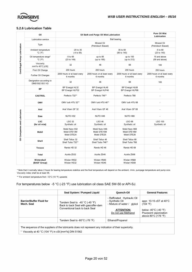
5.2.6 Lubrication Table
Oil Pure Oil MistLubrication
Lubrication service
TypeMineral Oil
(Petroleum Based)
Ambient temperature°C (°F)
-5 to 60(23 to 140)
Oil temperature range*°C (°F)
15 and above(59 and above)
Viscositymm²/s 40°C [cSt] 100
First Oil Change 200 hours
Further Oil Changes2000 hours or at least every
6 months
Designation according toDIN51502 ISO VG 100
BP -
CASTROL -
OMV -
Aral -
Esso -
LSC(for oil mist)
LSO 100Synthetic oil
Mobil -
Shell -
Texaco -
Total -
Wintershall(BASF Group) -
** For ambient temperature from -12°C (10 °F) upwards
* Note that it normally takes 2 hours for bearing temperature stabilize and the final temperature will depend on the ambient, r/min, pumpage temperature and pump size. Viscosity index shall be at least 95.
Cen
trifu
gal P
ump
Lubr
icat
ion
Ball bearing
Mineral Oil(Petroleum Based)
-20 to 35(-4 to 95)
-5 to 65(23 to 149)
32
2000 hours or at least every 6 months
35 to 60(95 to 140)
up to 85(up to 185)
up to 100(up to 212)
Aral Vitam GF 32
NUTO H32
BP Energol HL46BP Energol HLP46
Perfecto T46**
Azolla ZS32
LSO 46Synthetic oil
Rando HD 32
Shell Tellus 46Shell Turbo T46**
Rando HD 46
Wiolan HN32Wiolan HS32
46
200 hours
2000 hours or at least every 6 months
46
LSO 32Synthetic oil
Mobil Nuto H32Mobil DTE13MMobil DTE24
Shell Tellus 32Shell Turbo T32**
68
200 hours
2000 hours or at least every 6 months
68
Aral Vitam GF 68
Mobil Nuto H46Mobil DTE15MMobil DTE25
Aral Vitam GF 46
NUTO H46
Oil Bath and Purge Oil Mist Lubrication
BP Energol HL68BP Energol HLP68
Perfecto T68
OMV turb HTU 68
32
BP Energol HL32BP Energol HLP32
Perfecto T32**
OMV turb HTU 32**
200 hours
OMV turb HTU 46**
Oil
Com
pani
es a
nd L
ubri
cant
s
Shell Tellus 68Shell Turbo T68
Rando HD 68
Azolla ZS68
Wiolan HN68Wiolan HS68
NUTO H68
LSO 68Synthetic oil
Mobil Nuto H68Mobil DTE16MMobil DTE26
Azolla ZS46
Wiolan HN46Wiolan HS46
For temperatures below -5 °C (-23 °F) use lubrication oil class SAE 5W-50 or API-SJ.
Seal System / Pumped Liquid Quench-Oil General Features
Barrier/Buffer Fluid for Mech. Seal
Tandem Seal to -40 °C (-40 °F) Back to back Seal with gascoffer-dam Conventional back to back Seal
- Raffinated Hydraulic Oil - Synthetic Oil - Mixture of water / glykol
ATTENTION: Do not use Methanol
appr. 10-15 cST at 40°C (104 °F) below -40°C (-40 °F) Pourpoint vaporization above 80°C (176 °F)
Tandem Seal to -60°C (-76 °F) Ethanol/Propanol The sequence of the suppliers of the lubricants does not represent any indication of their superiority.
¹ Viscosity at 40 °C (104 °F) in cSt [mm²/s] DIN 51562
WXB USER INSTRUCTIONS ENGLISH – 05/16
Page 21 von 52
5.2.7 Lubrication The bearing housing shall be filled with proper lubricating oil prior to start up. If the pump will be started after a longer storage period, the bearing housing should be first flushed and cleaned with gasoline. It is not necessary to remove the preservation oil as this will mix up thoroughly with the lubrication oil. Lubrication is provided by the pumping effect of the rotating ball bearings. Maintaining the correct oil level (middle of the oil sight glass) ensures that the lower ball bearing is covered with oil. For recommended lubricating oils refer to the lubrication table 5.2.6
5.2.8 Oil change After first start up, the oil shall be changed after 200 service hours. Every further oil change shall take place after about 2000 service hours or at least every 6 month. To change the oil, use the following procedure: a) Remove the reservoir (for some type of oilers you
must loose a fixing screw or lock nut, refer to section 5.2.3 Oil level).
b) Open the oil drain on the bearing housing to remove the oil.
c) Close the oil drain and fill in Oil through the oiler until the oil level reaches the bottom of the sight glass.
d) Fill the reservoir and put it quickly to the body of the oiler. Observe the level in the reservoir. It will decrease until the required oil level is reached (middle of the sight glass). Ensure that enough oil remains in the reservoir.
e) If necessary, the oil level can be adjusted by refering to section 5.2.3 Oil level.
5.2.9 Oil level The correct oil level is in the middle of the oil sight glass and shall be checked when pump is not in operation. Periodically check if the lubricating oil is mixed with any condensed water. Careful opening of the oil drain during a stop of the pump will show any water.
Use a spirit level to check the horizontal alignment of the bearing housing.
A too high oil level will result in higher bearing temperatures and therefore poorer lubrication.
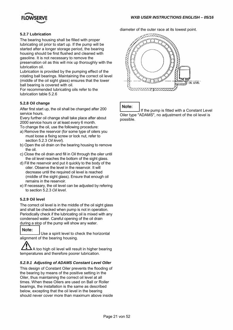
5.2.9.1 Adjusting of ADAMS Constant Level Oiler This design of Constant Oiler prevents the flooding of the bearing by means of the positive setting in the Oiler, thus maintaining the correct oil level at all times. When these Oilers are used on Ball or Roller bearings, the installation is the same as described below, excepting that the oil level in the bearing should never cover more than maximum above inside
diameter of the outer race at its lowest point.
If the pump is fitted with a Constant Level Oiler type "ADAMS", no adjustment of the oil level is possible.
WXB USER INSTRUCTIONS ENGLISH – 05/16
Page 22 von 52
5.2.10 Lubrication The bearing housing shall be filled with proper lubricating oil prior to start up. If the pump will be started after a longer storage period, the bearing housing should be first flushed and cleaned with gasoline. It is not necessary to remove the preservation oil as this will mix up thoroughly with the lubrication oil. Lubrication is provided by the pumping effect of the rotating ball bearings. Maintaining the correct oil level (middle of the oil sight glass) ensures that the lower ball bearing is covered with oil. For recommended lubricating oils refer to the lubrication table 5.2.6
5.2.11 Oil change After first start up, the oil shall be changed after 200 service hours. Every further oil change shall take place after about 2000 service hours or at least every 6 month. To change the oil, use the following procedure: a) Remove the reservoir (for some type of oilers you
must loose a fixing screw or lock nut, refer to section 5.2.3 Oil level).
b) Open the oil drain on the bearing housing to remove the oil.
c) Close the oil drain and fill in Oil through the oiler until the oil level reaches the bottom of the sight glass.
d) Fill the reservoir and put it quickly to the body of the oiler. Observe the level in the reservoir. It will decrease until the required oil level is reached (middle of the sight glass). Ensure that enough oil remains in the reservoir.
e) If necessary, the oil level can be adjusted by refering to section 5.2.3 Oil level.
5.2.12 Oil level The correct oil level is in the middle of the oil sight glass and shall be checked when pump is not in operation. Periodically check if the lubricating oil is mixed with any condensed water. Careful opening of the oil drain during a stop of the pump will show any water.
Use a spirit level to check the horizontal alignment of the bearing housing.
A too high oil level will result in higher bearing temperatures and therefore poorer lubrication.
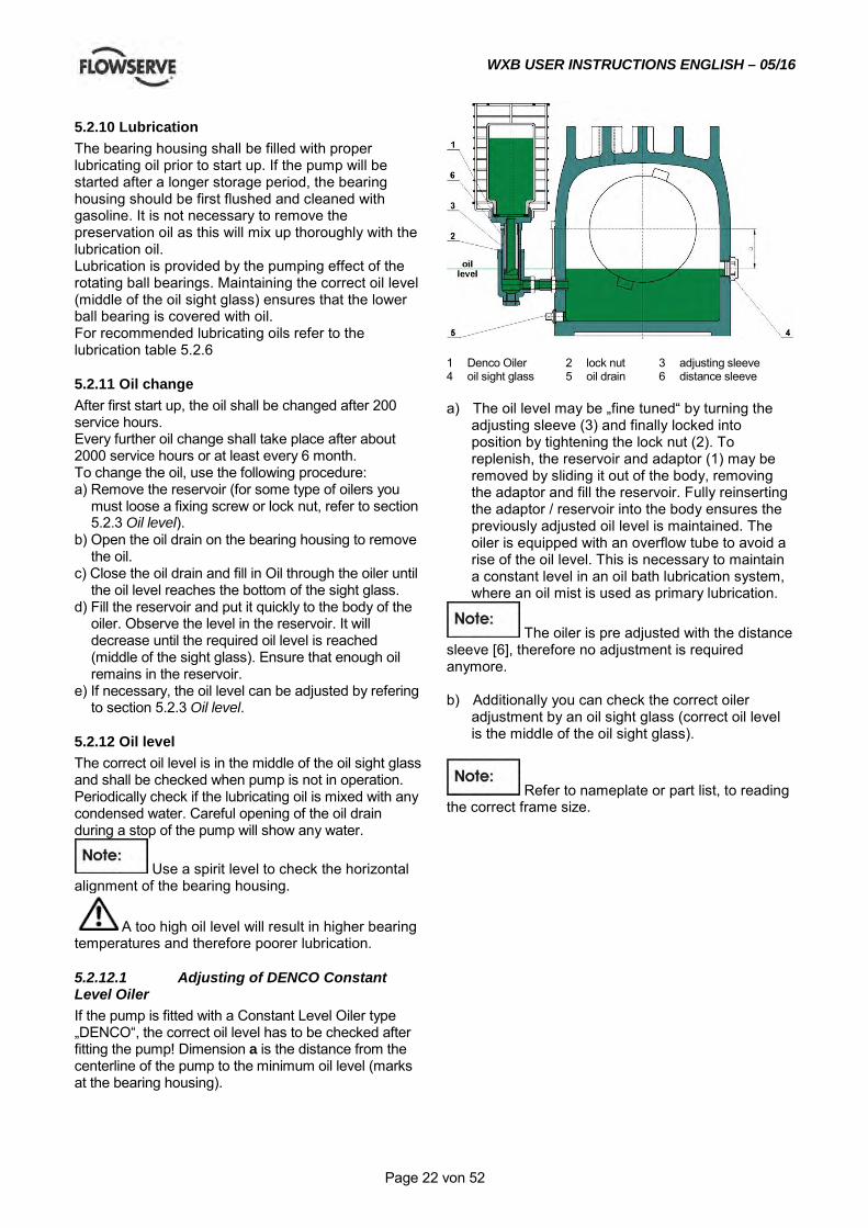
5.2.12.1 Adjusting of DENCO Constant Level Oiler If the pump is fitted with a Constant Level Oiler type „DENCO“, the correct oil level has to be checked after fitting the pump! Dimension a is the distance from the centerline of the pump to the minimum oil level (marks at the bearing housing).
1 Denco Oiler 2 lock nut 3 adjusting sleeve 4 oil sight glass 5 oil drain 6 distance sleeve a) The oil level may be „fine tuned“ by turning the
adjusting sleeve (3) and finally locked into position by tightening the lock nut (2). To replenish, the reservoir and adaptor (1) may be removed by sliding it out of the body, removing the adaptor and fill the reservoir. Fully reinserting the adaptor / reservoir into the body ensures the previously adjusted oil level is maintained. The oiler is equipped with an overflow tube to avoid a rise of the oil level. This is necessary to maintain a constant level in an oil bath lubrication system, where an oil mist is used as primary lubrication.
The oiler is pre adjusted with the distance sleeve [6], therefore no adjustment is required anymore. b) Additionally you can check the correct oiler
adjustment by an oil sight glass (correct oil level is the middle of the oil sight glass).
Refer to nameplate or part list, to reading the correct frame size.
WXB USER INSTRUCTIONS ENGLISH – 05/16
Page 23 von 52
5.2.13 Lubrication The bearing housing shall be filled with proper lubricating oil prior to start up. If the pump will be started after a longer storage period, the bearing housing should be first flushed and cleaned with gasoline. It is not necessary to remove the preservation oil as this will mix up thoroughly with the lubrication oil. Lubrication is provided by the pumping effect of the rotating ball bearings. Maintaining the correct oil level (middle of the oil sight glass) ensures that the lower ball bearing is covered with oil. For recommended lubricating oils refer to the lubrication table 5.2.6
5.2.14 Oil change After first start up, the oil shall be changed after 200 service hours. Every further oil change shall take place after about 2000 service hours or at least every 6 month. To change the oil, use the following procedure: a) Remove the reservoir (for some type of oilers you
must loose a fixing screw or lock nut, refer to section 5.2.3 Oil level).
b) Open the oil drain on the bearing housing to remove the oil.
c) Close the oil drain and fill in Oil through the oiler until the oil level reaches the bottom of the sight glass.
d) Fill the reservoir and put it quickly to the body of the oiler. Observe the level in the reservoir. It will decrease until the required oil level is reached (middle of the sight glass). Ensure that enough oil remains in the reservoir.
e) If necessary, the oil level can be adjusted by refering to section 5.2.3 Oil level.
5.2.15 Oil level The correct oil level is in the middle of the oil sight glass and shall be checked when pump is not in operation. Periodically check if the lubricating oil is mixed with any condensed water. Careful opening of the oil drain during a stop of the pump will show any water.
Use a spirit level to check the horizontal alignment of the bearing housing.
A too high oil level will result in higher bearing temperatures and therefore poorer lubrication.
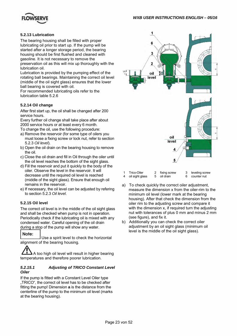
5.2.15.1 Adjusting of TRICO Constant Level Oiler If the pump is fitted with a Constant Level Oiler type „TRICO“, the correct oil level has to be checked after fitting the pump! Dimension a is the distance from the centerline of the pump to the minimum oil level (marks at the bearing housing).
1 Trico-Oiler 2 fixing screw 3 leveling screw 4 oil sight glass 5 oil drain 6 counter nut
a) To check quickly the correct oiler adjustment,
measure the dimension x from the oiler-rim to the minimum oil level (lower mark at the bearing housing). After that check the dimension from the oiler rim to the adjusting screw and compare it with the dimension x, if required turn the adjusting nut with tolerances of plus 0 mm and minus 2 mm (see figure), and fix it.
b) Additionally you can check the correct oiler adjustment by an oil sight glass (minimum oil level is the middle of the oil sight glass).
WXB USER INSTRUCTIONS ENGLISH – 05/16
Page 24 von 52
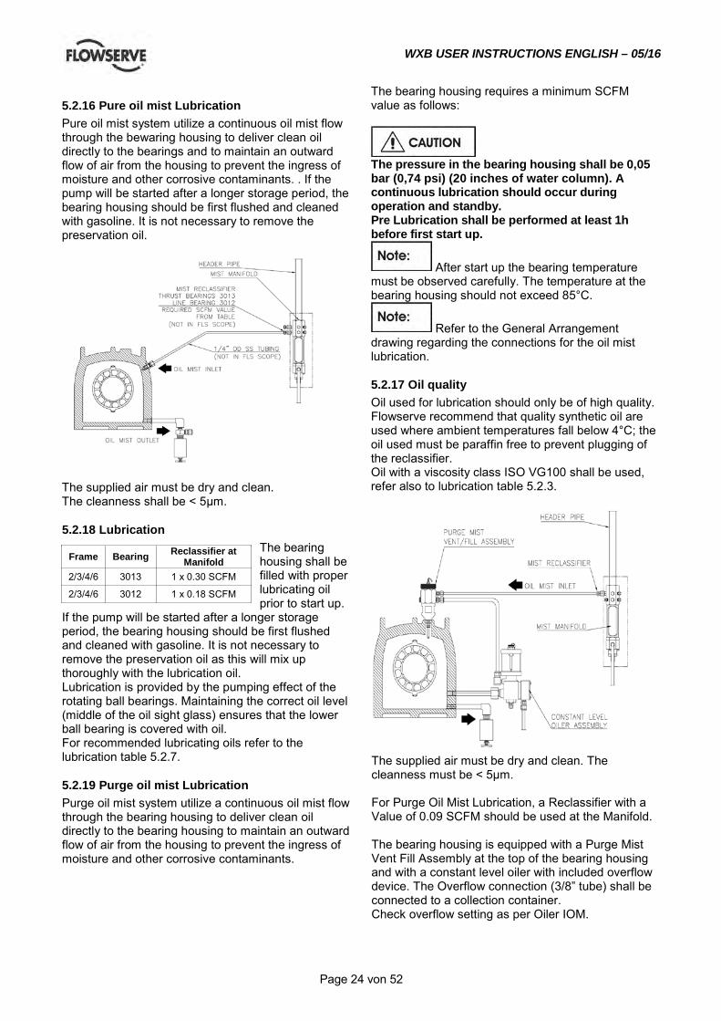
5.2.16 Pure oil mist Lubrication Pure oil mist system utilize a continuous oil mist flow through the bewaring housing to deliver clean oil directly to the bearings and to maintain an outward flow of air from the housing to prevent the ingress of moisture and other corrosive contaminants. . If the pump will be started after a longer storage period, the bearing housing should be first flushed and cleaned with gasoline. It is not necessary to remove the preservation oil.
The supplied air must be dry and clean. The cleanness shall be < 5µm.
The bearing housing requires a minimum SCFM value as follows:
The pressure in the bearing housing shall be 0,05 bar (0,74 psi) (20 inches of water column). A continuous lubrication should occur during operation and standby. Pre Lubrication shall be performed at least 1h before first start up.
After start up the bearing temperature must be observed carefully. The temperature at the bearing housing should not exceed 85°C.
Refer to the General Arrangement drawing regarding the connections for the oil mist lubrication.
5.2.17 Oil quality Oil used for lubrication should only be of high quality. Flowserve recommend that quality synthetic oil are used where ambient temperatures fall below 4°C; the oil used must be paraffin free to prevent plugging of the reclassifier. Oil with a viscosity class ISO VG100 shall be used, refer also to lubrication table 5.2.3.
5.2.18 Lubrication The bearing housing shall be filled with proper lubricating oil prior to start up.
If the pump will be started after a longer storage period, the bearing housing should be first flushed and cleaned with gasoline. It is not necessary to remove the preservation oil as this will mix up thoroughly with the lubrication oil. Lubrication is provided by the pumping effect of the rotating ball bearings. Maintaining the correct oil level (middle of the oil sight glass) ensures that the lower ball bearing is covered with oil. For recommended lubricating oils refer to the lubrication table 5.2.7.
5.2.19 Purge oil mist Lubrication Purge oil mist system utilize a continuous oil mist flow through the bearing housing to deliver clean oil directly to the bearing housing to maintain an outward flow of air from the housing to prevent the ingress of moisture and other corrosive contaminants.
The supplied air must be dry and clean. The cleanness must be < 5µm. For Purge Oil Mist Lubrication, a Reclassifier with a Value of 0.09 SCFM should be used at the Manifold. The bearing housing is equipped with a Purge Mist Vent Fill Assembly at the top of the bearing housing and with a constant level oiler with included overflow device. The Overflow connection (3/8” tube) shall be connected to a collection container. Check overflow setting as per Oiler IOM.
Frame Bearing Reclassifier at Manifold
2/3/4/6 3013 1 x 0.30 SCFM
2/3/4/6 3012 1 x 0.18 SCFM
WXB USER INSTRUCTIONS ENGLISH – 05/16
Page 25 von 52
The pressure in the bearing housing shall be 0,05 bar (0,74 psi) (20 inches of water column). A continuous oil mist lubrication should be occur during operation and stand by.
After start up the bearing temperature must be observed carefully. The temperature at the bearing housing should not exceed 85°C.
Refer to the GA-drawing regarding the connections to the supply systems.
5.2.20 Oil change After first start up, the oil shall be changed after 200 service hours. Every further oil change shall take place after about 2000 service hours or at least every 6 month. To change the oil use the following procedure:
a) Open the oil drain on the bearing housing to remove
the oil. b) Close the oil drain and fill in Oil through the vent
connection on the bearing cover until the oil level reaches the middle of the sight glass.
c) Fill the reservoir of the constant level oiler. d) If necessary, the oil level can be adjusted by
referring to section 5.2.4 Oil level.
5.2.21 Oil level The correct oil level is in the middle of the oil sight glass and shall be checked when pump is not in operation. Periodically check if the lubricating oil is mixed with any condensed water. Careful opening of the oil drain during a stop of the pump will show any water.
During operation a small increase of the oil level can occur due to the oil mist supply.
A too high oil level will result in higher bearing temperatures and therefore poorer lubrication.
5.3 Impeller clearance No axial adjustment of the rotor is necessary.
The rotor is not moving during operation.
5.4 Direction of rotation
The sense of rotation of the pump is clockwise (CW); looking from the coupling to the shaft end of the pump.
The rotation of the driver shall be checked.
5.5 Guarding Be sure that the coupling guard is mounted correctly at the baseplate prior to start up.
5.6 Priming and auxiliary supplies The pump must be completely primed prior to start up. a) The pump casing is considered as self venting,
so no vent connections are provided. b) Auxiliary systems, e.g. barrier /buffer fluid
systems, cooling circuits, shall be filled according to the user instructions.
Ensure that balance line is open. Closed balance line leads immediately to a damage of the pump. (This does not apply for opposed impeller pumps). In case of an external balance line it is recommended to install a pressure gauge right after the pump. The measured pressure must not be more than 2 bar (29 psi) above suction pressure.
5.7 Starting the pump a) Start the driver according to the specification.
(Refer to driver IOM).
Pumps are usually started against closed discharge valve.
b) Check the discharge and suction pressure gauge to verify the pumps delivered head. Open the discharge valve slowly, until the pump reaches the specified operation point. The pump must operate smoothly, and the vibration must be below 3 mm/s (0.12 in./sec) (API 610 vibration limits).
The discharge valve must be opened within 30 sec. after start up. Longer operation against closed discharge valve will damage the pump. If a minimum flow valve is installed, take pressure gauge readings to verify the correct operation.
If the backpressure of the discharge pipe is sufficient, pumps can be started against open valve.
Ensure that your driver is capable deliver the higher torque required by starting against open valve.
To prevent the pump from reverse rotation after shut down, the installation of a check valve is recommended. Although the pump is not affected by reverse rotation because of spezial couppling design , it can be an issue with the driver. Check the discharge and suction pressure gauge to verify the pumps delivered head.
WXB USER INSTRUCTIONS ENGLISH – 05/16
Page 26 von 52
The pump must operate smoothly, and the vibration must be below 3 mm/s (0.12 in./sec) (API 610 vibration limits). If a minimum flow valve is installed, take pressure gauge readings to verify the correct operation.
c) Check the pipe system against any leakage. d) Check the mechanical seal against any leakage.
Right after start up a minor leakage of the mechanical seal is quite normal. Normally this leakage disappears after few minutes of operation.
5.8 Operation a) Verify that the pump is operating within the
specified limits, min/max flow, pressure, temperature, vibration, power
b) The bearing housing temperature shall not exceed 80 °C (176 °F). If higher bearing temperature are observed, check the viscosity grade of the used lubrication oil.
The minimum viscosity is 10 cSt at the expected oil temperature. (Oil temperature = bearing gland temperature + 10 °C (50 °F))
c) From time to time check the pump shaft seal. Leakage of 10 - 20 drops per hour is also with a mechanical shaft seal unavoidable.
d) Observe the power consumption of the pump to detect excessive wear.
5.9 Stopping and Shutdown a) Close the outlet valve, but ensure that the pump
runs in this condition for no more than a few seconds.
b) Stop the pump. c) Switch off flushing and/or cooling/ heating liquid
supplies at a time appropriate to the process. d) For prolonged shut-downs and especially when
ambient temperatures are likely to drop below freezing point, the pump and any cooling and flushing arrangements must be drained or otherwise protected.
For automatic start/stop operation of the pump, ensure that all steps described in chapter 5.6, 5.7, 5.8 and 5.9 are implemented in the control logic.
5.10 Hydraulic, mechanical and electrical duty This product has been supplied to meet the performance specifications of your purchase order, however it is understood that during the life of the product these may change. The following notes will help the user to decide how to evaluate the implications of any change. If in doubt contact your nearest Flowserve office.
5.10.1 Specific gravity (SG) Pump capacity and total head in meters (feet) do not change with SG, however pressure displayed on a pressure gauge is directly proportional to SG. Power absorbed is also directly proportional to SG. It is therefore important to check that any change in SG will not overload the pump driver or over-pressurize the pump.
5.10.2 Viscosity For a given flow rate the total head reduces with increased viscosity and increases with reduced viscosity. Also for a given flow rate the power absorbed increases with increased viscosity, and reduces with reduced viscosity. It is important that checks are made with your nearest Flowserve office if changes in viscosity are planned.
5.10.3 Pump speed Changing pump speed effects flow, total head, power absorbed, NPSHR, noise and vibration. Flow varies in direct proportion to pump speed. Head varies as speed ratio squared. Power varies as speed ratio cubed. If increasing speed it is important therefore to ensure the maximum pump working pressure is not exceeded, the driver is not overloaded, NPSHA>NPSHR, and that noise and vibration are within local requirements and regulations.
5.10.4 Net positive suction head (NPSHA) NPSH available (NPSHA.) is a measure of the energy available in the pumped liquid, above its vapour pressure, at the pump suction branch. NPSH required (NPSHR.) - is a measure of the energy required in the pumped liquid, above its vapour pressure, to prevent the pump from cavitating. It is important that NPSHA >NPSHR. The margin between NPSHA >NPSHR should be as large as possible. If any change in NPSHA is proposed, ensure these margins are not significantly eroded. Refer to the pump performance curve to determine exact requirements particularly if flow has changed. If in doubt please consult your nearest Flowserve office for advise and details of the minimum allowable margin for your application.
5.10.5 Pumped flow Flow must not fall outside the minimum and maximum continuous safe flow shown on the pump performance curve and/or data sheet.
6.0 MAINTENANCE
6.1 General
It is the plant operator's responsibility to ensure that all maintenance, inspection and assembly work is carried out by authorized and

WXB USER INSTRUCTIONS ENGLISH – 05/16
Page 27 von 52
qualified personnel who have adequately familiarized themselves with the subject matter by studying this manual in detail. (See also section 1.6.2.) Any work on the machine must be performed when it is at a standstill. It is imperative that the procedure for shutting down the machine is followed, as described in section 5.9. On completion of work all guards and safety devices must be re-installed and made operative again. Before restarting the machine, the relevant instructions listed in section 5, Commissioning, start up, operation and shut down must be observed. Oil and grease leaks may make the ground slippery. Machine maintenance must always begin and finish by cleaning the ground and the exterior of the machine. If platforms, stairs and guard rails are required for maintenance, they must be placed for easy access to areas where maintenance and inspection are to be carried out. The positioning of these accessories must not limit access or hinder the lifting of the part to be serviced. When air or compressed inert gas is used in the maintenance process, the operator and anyone in the vicinity must be careful and have the appropriate protection. Do not spray air or compressed inert gas on skin. Do not direct an air or gas jet towards other people. Never use air or compressed inert gas to clean clothes. Before working on the pump, take measures to prevent an uncontrolled start. Put a warning board on the starting device with the words: "Machine under repair: do not start". With electric drive equipment, lock the main switch open and withdraw any fuses. Put a warning board on the fuse box or main switch with the words: "Machine under repair: do not connect". Never clean equipment with inflammable solvents or carbon tetrachloride. Protect yourself against toxic fumes when using cleaning agents.
6.2 Maintenance schedule
It is recommended that a maintenance plan and schedule is adopted, in line with these User Instructions, to include the following:
a) Any auxiliary systems installed must be monitored, if necessary, to ensure they function correctly.
b) Gland packings must be adjusted correctly to give visible leakage and concentric alignment of the gland follower to prevent excessive temperature of the packing or follower.
c) Check for any leaks from gaskets and seals. The correct functioning of the shaft seal must be checked regularly.
d) Check bearing lubricant level, and if the hours run show a lubricant change is required.
e) Check that the duty condition is in the safe operating range for the pump.
f) Check vibration, noise level and surface temperature at the bearings to confirm satisfactory operation.
g) Check dirt and dust is removed from areas around close clearances, bearing housings and motors.
h) Check coupling alignment and re-align if necessary.
Our specialist service personnel can help with preventative maintenance records and provide condition monitoring for temperature and vibration to identify the onset of potential problems. If any problems are found the following sequence of actions should take place: a) Refer to section 8, Faults; causes and remedies,
for fault diagnosis. b) Ensure equipment complies with the
recommendations in this manual. c) Contact Flowserve if the problem persists.
6.2.1 Routine Inspection (daily/weekly)
The following checks should be made and the appropriate action taken to remedy any deviations. a) Check operating behavior; ensure noise,
vibration and bearing temperatures are normal. b) Check that there are no abnormal fluid or
lubricant leaks (static and dynamic seals) and that any sealant systems (if fitted) are full and operating normally.
c) Check that shaft seal leaks are within acceptable limits.
d) Check the level and condition of lubrication oil. On grease lubricated pumps, check running hours since last recharge of grease or complete grease change.
e) Check any auxiliary supplies eg. heating/cooling (if fitted) are operating correctly.
f) Refer to the manuals of any associated equipment if routine checks needed.
WXB USER INSTRUCTIONS ENGLISH – 05/16
Page 28 von 52
6.2.2 Periodic Inspection (every 6 Month)
a) Check foundation bolts for security of attachment and corrosion.
b) Check pump operation hours to determine if bearing lubricant shall be changed.
c) The coupling should be checked for correct alignment and worn driving elements.
Refer to the manuals of any associated equipment for periodic checks needed.
6.3 Spare parts
6.3.1 Ordering of spares When ordering spare parts we need the following information: 1. pump type and pump size 2. serial number of the pump 3. number of the required spare parts 4. reference number and name of the part as listed
in the part list or in the sectional drawing Example: for WXB pump: 3WXB-10A8, serial number G202222/01 1 piece impeller Pos. 2200.1 The serial number of each pump is indicated on the name plate. If the material should be changed from the original delivered one, additionally indicate the exact material specification. If ordered impellers shall have smaller or larger outer diameter, indicate also with your order. Without a special remark the spare
impellers will be delivered with the diameter of the original impellers. If you need the wear rings oversized or undersized, please indicate, otherwise the wear rings will be delivered with standard size. To ensure continuous satisfactory operation, replacement parts to the original design specification should be obtained from Flowserve. Any change to the original design specification (modification or use of a non-standard parts) will invalidate the pump’s safety certification.
6.3.2 Storage of spares Spares should be stored in a clean dry area away from vibration. Inspection and retreatment of metallic surfaces (if necessary) with preservative is recommended at a 6 monthly interval.
6.4 Recommended spares Spares Recommended
Part Start up Normal Maintenance No.of identical pumps 1 - 3 4 - 6 7+ 1 - 3 4 - 6 7 - 9 10+
Case 1
Head (case cover and stuffing box) 1
Bearing housing 1
Shaft (w/key) 1 1 2 1
Impeller 1 1 2 3
Wear rings (set) 1 1 1 1 1 2 3
Bearings complete (antifriction,radial) 1 2 3 1 2 3 3
Bearings complete (antifriction,thrust) 1 2 3 1 2 3 3
Mechanical seal complete (Cartridge) 1 2 3 1 2 3 3
Shaft sleeve and interstage bush (set) 1 2 3 1 2 3 3
Gaskets, O-rings (set) 1 2 3 1 2 3 3
Balance drum and drum head (set) 1 1 1 1 1 2 3
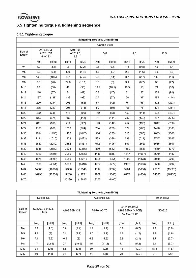
WXB USER INSTRUCTIONS ENGLISH – 05/16
Page 29 von 52
6.5 Tightening torque & tightening sequence
6.5.1 Tightening torque Tightening Torque MA Nm (lbf.ft)
Carbon Steel
Size of Screw
A193 B7M, A320 L7M (NACE)
A193 B7, A320 L7,
8.8 3.6 4.6 10.9
[Nm] [lbf.ft] [Nm] [lbf.ft] [Nm] [lbf.ft] [Nm] [lbf.ft] [Nm] [lbf.ft]
M4 4.2 (3.1) 3 (2.2) 0.8 (0.6) 1.1 (0.8) 4.6 (3.4)
M5 8.3 (6.1) 5.9 (4.4) 1.6 (1.2) 2.2 (1.6) 8.6 (6.3)
M6 14.2 (10.5) 10.1 (7.4) 2.8 (2.1) 3.7 (2.7) 14.9 (11)
M8 35 (26) 24.6 (18.1) 6.8 (5) 9.1 (6.7) 36 (27)
M10 68 (50) 48 (35) 13.7 (10.1) 18.3 (13) 71 (52)
M12 118 (87) 84 (62) 23 (17) 31 (23) 123 (91)
M14 187 (138) 133 (98) 37 (27) 50 (37) 195 (144)
M16 290 (214) 206 (152) 57 (42) 76 (56) 302 (223)
M18 335 (247) 295 (218) 80 (59) 106 (78) 421 (311)
M20 472 (348) 415 (306) 112 (83) 150 (111) 592 (437)
M22 644 (475) 567 (418) 151 (111) 202 (149) 807 (595)
M24 811 (598) 714 (527) 193 (142) 257 (190) 1017 (750)
M27 1193 (880) 1050 (774) 284 (209) 379 (280) 1496 (1103)
M30 1614 (1190) 1420 (1047) 386 (285) 515 (380) 2033 (1500)
M33 2191 (1616) 1928 (1422) 523 (386) 697 (514) 2747 (2026)
M36 2820 (2080) 2482 (1831) 672 (496) 897 (662) 3535 (2607)
M39 3645 (2689) 3208 (2366) 870 (642) 1160 (856) 4569 (3370)
M42 3920 (2891) 3980 (2936) 1146 (845) 1447 (1067) 5670 (4182)
M45 4875 (3596) 4950 (3651) 1425 (1051) 1800 (1328) 7050 (5200)
M48 5899 (4351) 5990 (4418) 1724 (1272) 2178 (1606) 8530 (6292)
M64 14083 (10388) 14300 (10548) 4117 (3037) 5201 (3836) 20370 (15025)
M68 16998 (12538) 17260 (12731) 4969 (3665) 6277 (4630) 24580 (18130)
M76 25230 (18610) 8270 (6100)
Tightening Torque MA Nm (lbf.ft)
Duplex SS Austenitic SS other alloys
Size of Screw
S32760, S31803, 1.4462 A193 B8M Cl2 A4-70, A2-70
A193 B8/B8M, A193 B8MA (NACE)
A2-50, A4-50 N08825
[Nm] [lbf.ft] [Nm] [lbf.ft] [Nm] [lbf.ft] [Nm] [lbf.ft] [Nm] [lbf.ft]
M4 2.1 (1.5) 3.2 (2.4) 1.9 (1.4) 0.9 (0.7) 1.1 (0.8)
M5 4.1 (3) 6.4 (4.7) 3.6 (2.7) 1.6 (1.2) 2.2 (1.6)
M6 7.1 (5.2) 10.9 (8) 6.3 (4.6) 2.9 (2.1) 3.7 (2.7)
M8 17 (12.5) 27 (19.9) 15 (11.2) 7.1 (5.2) 9.1 (6.7)
M10 34 (25) 52 (38) 30 (22) 14 (10.3) 18.3 (13)
M12 59 (44) 91 (67) 51 (38) 24 (17.7) 31 (23)
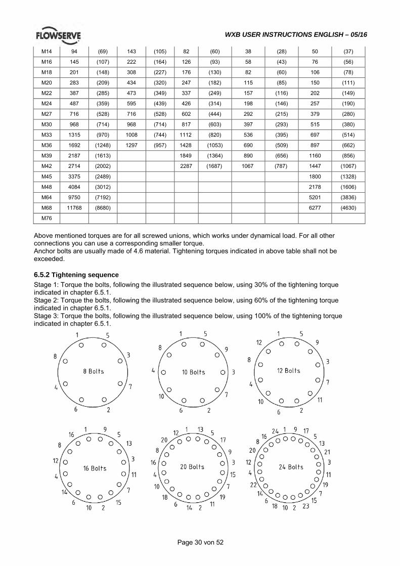
WXB USER INSTRUCTIONS ENGLISH – 05/16
Page 30 von 52
M14 94 (69) 143 (105) 82 (60) 38 (28) 50 (37)
M16 145 (107) 222 (164) 126 (93) 58 (43) 76 (56)
M18 201 (148) 308 (227) 176 (130) 82 (60) 106 (78)
M20 283 (209) 434 (320) 247 (182) 115 (85) 150 (111)
M22 387 (285) 473 (349) 337 (249) 157 (116) 202 (149)
M24 487 (359) 595 (439) 426 (314) 198 (146) 257 (190)
M27 716 (528) 716 (528) 602 (444) 292 (215) 379 (280)
M30 968 (714) 968 (714) 817 (603) 397 (293) 515 (380)
M33 1315 (970) 1008 (744) 1112 (820) 536 (395) 697 (514)
M36 1692 (1248) 1297 (957) 1428 (1053) 690 (509) 897 (662)
M39 2187 (1613) 1849 (1364) 890 (656) 1160 (856)
M42 2714 (2002) 2287 (1687) 1067 (787) 1447 (1067)
M45 3375 (2489) 1800 (1328)
M48 4084 (3012) 2178 (1606)
M64 9750 (7192) 5201 (3836)
M68 11768 (8680) 6277 (4630)
M76
Above mentioned torques are for all screwed unions, which works under dynamical load. For all other connections you can use a corresponding smaller torque. Anchor bolts are usually made of 4.6 material. Tightening torques indicated in above table shall not be exceeded.
6.5.2 Tightening sequence Stage 1: Torque the bolts, following the illustrated sequence below, using 30% of the tightening torque indicated in chapter 6.5.1. Stage 2: Torque the bolts, following the illustrated sequence below, using 60% of the tightening torque indicated in chapter 6.5.1. Stage 3: Torque the bolts, following the illustrated sequence below, using 100% of the tightening torque indicated in chapter 6.5.1.
WXB USER INSTRUCTIONS ENGLISH – 05/16
Page 31 von 52
6.6 Setting impeller clearance No axial adjustment of the rotor is necessary.
The rotor is not moving during operation.
6.7 Disassembly
See section 1.6, Safety, before dismantling the pump.
Before dismantling the pump for overhaul, ensure genuine Flowserve replacement parts are available. Refer to sectional drawings for part numbers and identification.
6.7.1 Dismantling of pump 1) Completely drain the pump by using the drain
connection. By pumping explosive or toxic media, flush your system with Nitrogen.
2) Remove coupling guard and uncouple the pump from the motor. Pull off the coupling hub from the pump shaft [2100] and take out the key [6700.2].
Ensure that the motor is locked against start up.
If applied pull off the vane. 3) Drain the oil from both bearing housings, using the
plug [6569.1]. If required disconnect all auxiliary pipings and auxiliary devices like vibration probes, temperature probes, etc.
4) Due to the design with casing [1100] the complete rotor of the pump can be taken out of the barrel without disconnecting the suction or discharge flange connections. To facilitate the moving out of the complete rotor through the casing [1100], push it by help with the hexagon head bolt [6577.3] and joining piece for barrel [3121.2] out of the barrel fit. Further insert a rod with a screwed end of 1“ pipe thread into the bore of the tool [9310] on the bearing housing. Now the complete rotor can be easily pulled out of the barrel. For further dismantling bring it to the workshop. If a spare hydraulic cartridge is available, this can be inserted into the barrel, and the pump is back in service in a few hours. If the whole pump should be removed, proceed with step 5) and 6).
5) The pump has to be disconnected from suction and discharge pipe. The alignment of the pump and driver has to be checked and put it down in writing.
6) Unscrew the mounting screws of the pump on the base plate. If the discharge casing were placed on the base plate by taper pin, remove them too. Lift
the pump to a clean area by crane or other lifting device where the pump can be disassembled.
6.7.2 Dismantling of the line bearing side 1) Loosen hexagon head bolt [6577.1] of both bearing
covers [3260.1] and [3260.3]. 2) Remove bearing cover [3260.1] together with
labyrinth ring [4330.3] and O-ring [4610.1] from the pump.
3) Unscrew hex nuts [6581.2] and remove carefully bearing housing [3200.2] and outer ring of radial roller bearing [3012] with the aid of a crane from the pump.
4) Now unscrew the shaft nut [2910.2] and pull off the locking plate [6541.2], washer [2905.2], bearing adaptor sleeve [2471.2], O-ring [4610.8] and inner ring of radial roller bearing [3012] from pump shaft.
5) To remove the inner ring of radial roller bearing [3012] from bearing adaptor sleeve [2471.2] use a pulling-off device or use two bushings whereas one is used as support and the other as mounting sleeve.
6) Now remove bearing cover [3260.3], if necessary.
Line bearing:
NU311 2WXB
NU313 3WXB
NU315 4WXB
NU315 6WXB
6.7.3 Dismantling of the thrust bearing side 1) Unscrew the mounting screw of fan case and
remove it. Unscrew the clamping screw of fan and pull it off from the pump shaft.
2) Loosen the hexagon head bolt [6577.1] from bearing cover [3260.1] and loosen the hexagon head bolt [6577.1] from bearing cover [3260.2].
3) Remove bearing cover [3260.1] together with labyrinth ring [4330.2] from the pump.
4) Unscrew hex nuts [6581.2] and remove carefully bearing housing [3200.1] with the aid of a crane from the pump.
5) Now unscrew the shaft nut [2910.1] and pull off the locking plate [6541.1], washer [2905.1], bearing adaptor sleeve [2471.1], O-ring [4610.2] and the two thrust ball bearings [3013] from pump shaft.
6) To remove the two thrust ball bearings [3013] from bearing adaptor sleeve [2471.1] use a pulling-off device or use two bushings whereas one is used as support and the other as mounting sleeve.
7) Now remove bearing cover [3260.2] ,if necessary. Thrust bearing:
7311 BECB (J),(M) 2WXB
7313 BECB (J),(M) 3WXB
7315 BEGAM (J),(M) 4WXB
7315 BEGAM (J),(M) 6WXB
WXB USER INSTRUCTIONS ENGLISH – 05/16
Page 32 von 52
6.7.4 Dismantling of mechanical seal 1) Secure the mechanical seal by putting the
mounting plates into the groove of the shaft sleeve. Loose the grub screws, and disconnect the seal piping.
Drain the seal system, if applicable.
2) Loose hex nuts [6581.4] and pull off mechanical seal cartridge from the shaft. [2100]
6.7.5 Dismantling of hydraulic cartridge 1) Start at the line bearing side first following chapter
6.7.2 and 6.7.4. 2) As next step dismantle the thrust bearing side
following chapter 6.7.3 and 6.7.4. 3) The further dismantling has to be executed from
the thrust bearing side. Remove the o-ring [4610.4] and draw the stuffing box housing [4110] out of the discharge casing [1140].
4) Open the hex nuts [6581.1] of the studs [6572.1] and dismantle the pump stage by stage beginning at thrust bearing side.
5) First off all loose the socket head cup screws [6579.2] at the balancing drum [6230]. Then remove the clamping ring [1240], which is fixing the retaining ring [2530]. Now pull the balance drum [6230] from the shaft.
6) Now take the cup spring [4263] and the diffuser last stage [1410.2]out of the pump.
7) Start to dismantle the pump stage by stage. All parts of a stage (impeller [2200.1, 2200.2], diffusers [1410.2, 1410.1] and stage casing [1160.1] have to be numbered to assure a reassemble in original sequence. The availability of a crane to secure the heavy parts would be very helpful, to avoid that they will fall on the shaft and damage or bend it.
8) Support the stage casing which is next to the discharge casing. Lift the discharge casing inclusive the bush [1600], which is fixed on it and also the diffuser of the last stage [1410.2] which is close in the casing. When necessary remove the bush from the discharge casing by loosen the socket head cap screws [6579.3]. By removing the o-ring [4610.6] out of the discharge casing with the help of a sharp tool also the diffuser can be removed.
9) Now draw off the impeller [2200.1] with the impeller wear ring [2300.1] from the shaft. Then take the key [6700.1] out of the groove and support the next stage casing [1160.1] which is closer to the suction casing and lift the last stage casing inclusive diffuser [1410.1] and casing wear ring from the pump.
10) As next step remove the interstage sleeve [2410] and the impeller [2200.1] with the impeller wear ring[2300.1] from the shaft. Now take again one key [6700.1] from the shaft and support the next
stage casing. Remove the next stage casing still you have reached the suction casing [1130].
11) Remove the impeller first stage [2200.2] with the impeller wear ring [2300.2]. Then you can draw the shaft out off the suction casing. Pull out the suction casing [1130] from the casing [1100]. In the suction casing you can find the casing wear ring for the first stage [1500.2].
Pumps equipped with an inducer have a separate stage casing in front of 1st stage impeller.
6.7.6 Dismantling of hydraulic cartridge with gasket
1) Start at the line bearing side first following chapter 6.7.2 and 6.7.4.
2) As next step dismantle the thrust bearing side following chapter 6.7.3 and 6.7.4.
3) The further dismantling has to be executed from the thrust bearing side. Draw the stuffing box housing [4110] out of the discharge casing [1140].
4) Open the hex nuts [6581.1] of the studs [6572.1] and dismantle the pump stage by stage beginning at thrust bearing side.
5) First off all loose the socket head cup screws [6579.2] at the balancing drum [6230]. Then remove the clamping ring [1240], which is fixing the retaining ring [2530]. Now pull the balance drum [6230] from the shaft.
6) Now take the cup spring [4263] and the diffuser last stage [1410.2]out of the pump.
7) Start to dismantle the pump stage by stage. All parts of a stage (impeller [2200.1, 2200.2], diffusers [1410.2, 1410.1] and stage casing [1160.1] have to be numbered to assure a reassemble in original sequence. The availability of a crane to secure the heavy parts would be very helpful, to avoid that they will fall on the shaft and damage or bend it.
8) Support the stage casing which is next to the discharge casing. Lift the discharge casing inclusive the bush [1600], which is fixed on it and also the diffuser of the last stage [1410.2] which is close in the casing. When necessary remove the bush from the discharge casing by loosen the socket head cap screws [6579.3]. By removing the gasket [4590.2] out of the discharge casing with the help of a sharp tool also the diffuser can be removed.
9) Now draw off the impeller [2200.1] with the impeller wear ring [2300.1] from the shaft. Then take the key [6700.1] out of the groove and support the next stage casing [1160.1] which is closer to the suction casing and lift the last stage casing inclusive diffuser [1410.1] and casing wear ring from the pump.
10) As next step remove the interstage sleeve [2410] and the impeller [2200.1] with the impeller wear ring[2300.1] from the shaft. Now take again one

WXB USER INSTRUCTIONS ENGLISH – 05/16
Page 33 von 52
key [6700.1] from the shaft and support the next stage casing. Remove the next stage casing still you have reached the suction casing [1130].
11) Remove the impeller first stage [2200.2] with the impeller wear ring [2300.2]. Then you can draw the shaft out off the suction casing. Pull out the suction casing [1130] from the casing [1100]. In the suction casing you can find the casing wear ring for the first stage [1500.2].
Pumps equipped with an inducer have a separate stage casing in front of 1st stage impeller.
12) Verify that gaskets [4590.7] and [4590.8] are still in the suction casing [1130]. Otherwise remove them from the barrel [1100].
6.8 Examination of parts 1) Check the casing wear ring and the impeller wear
ring against any wear. The diametrical clearance between the rings must not exceed twice the value in new condition.
2) Check all parts against corrosion and erosion. 3) Carefully check the coupling against any wear.
Rotate the angular contact bearing by hand, to check against abnormal sound. Check the bearing cages against any wear and the outer and inner race against running marks. Check the runout of the shafts. TIR (Total Indicated Runout) shall not exceed 0.04 mm/m (0.0005 in./ft) of length. TIR shall not exceed 0.08 mm (0.003 in.) over total shaft length.
6.8.1 Gap between particular parts
The diametrical gap between casing wear rings [1500.1, 1500.2] and impeller wear rings [2300.1, 2300.2] in assembled condition is:
Pump size Material Diametrical
gap diametrical gap between balance drum [6230] and
bush [1600] mm (in.)
2 WXB
Steel rings mm (in.) 0,4 (0.016)
0,3 (0.012) Stainless
rings mm (in.)
0,5 (0.019)
3 WXB
Steel rings mm (in.) 0,45 (0.017)
0,4 (0.016) Stainless
rings mm (in.)
0,55 (0.022)
4 WXB
Steel rings mm (in.) 0,45 (0.017)
0,35 (0.014) Stainless
rings mm (in.)
0,55 (0.022)
6 WXB
Steel rings mm (in.) 0,45 (0.017)
0,4 (0.016) Stainless
rings mm (in.)
0,55 (0.022)
The diametrical gap between diffuser [1410.1] or interstage bush [1610] and interstage sleeve [2410] is 0,25 mm (0.010 in.).
Gaps apply approximately for wear rings in assembled condition.
6.9 Assembly To assemble the pump consult the sectional drawings. Ensure threads, gasket and O-ring mating faces are clean. Apply thread sealant to non-face sealing pipe thread fittings.
6.9.1 Assembly of hydraulic cartridge
Be sure that the casing wear rings [1500.1,1500.2] are pressed in the stage casings [1160.1] respectively in the suction casing [1130], the impeller wear ring[2300.1, 2300.2] are pressed on the impellers [2200.1, 2200.2]. The rings should be fitted by tack welding or if necessary by grub screws. The same applies to the interstage bush [1610] in the diffusers [1410.1] and the packing seating ring [4133] in the stuffing box housing [4110]. 1) Assembling of the pump is easier in vertical
position (horizontal position is possible too). Use the reverse procedure as described in the chapter 6.7.5 Dismantling of hydraulic section.
2) Put the suction casing [1130] with the line bearing side down on a suitable support. Now insert the shaft in the suction casing screw it on a vertically positioned screw.
3) Put the key [6700.1] for the first stage in the shaft groove. Slide the first impeller [2200.2] from upwards carefully on the shaft till it touches the shoulder on the shaft. Adjust the shaft inclusive the impeller in reference to the suction casing by turning the shaft in the device. The right position is reached when the casing wear ring in the suction casing is even with the impeller wear ring of the first stage. This visual check is sufficient because the exact position of the shaft will be committed by assembling the thrust bearing.
4) Now put from upwards the stage casing [1160.1] together with the tightly sitting diffuser [1410.1] , o-ring [4610.7], interstage bush [1610] and casing wear ring [1500.1] over the shaft [2100] and the impeller [2200.1] down to the suction casing [1130].
5) Slight the interstage sleeve [2410] on the shaft, taking care that it catches the key [6700.1]. When it isn’t the case all parts on the shaft would be displaced to the thrust bearing and after the pump is complete assembled it would not turn.
6) Be sure to follow the reverse sequence of all parts
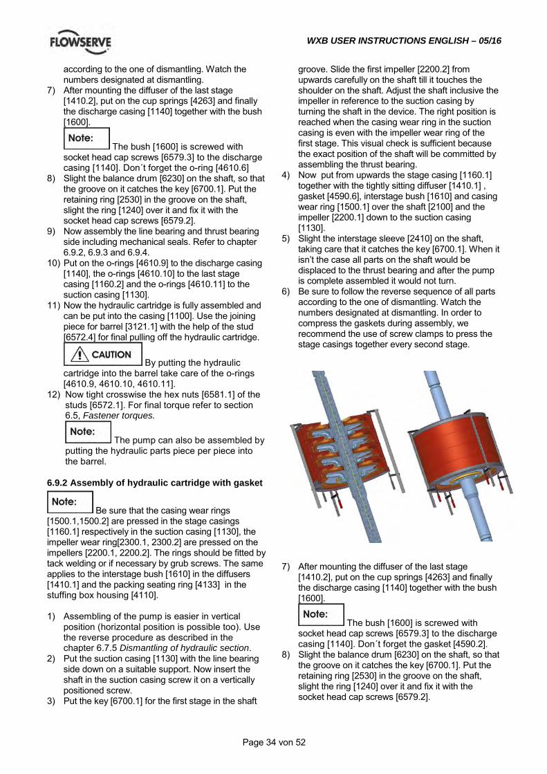
WXB USER INSTRUCTIONS ENGLISH – 05/16
Page 34 von 52
according to the one of dismantling. Watch the numbers designated at dismantling.
7) After mounting the diffuser of the last stage [1410.2], put on the cup springs [4263] and finally the discharge casing [1140] together with the bush [1600].
The bush [1600] is screwed with socket head cap screws [6579.3] to the discharge casing [1140]. Don´t forget the o-ring [4610.6]
8) Slight the balance drum [6230] on the shaft, so that the groove on it catches the key [6700.1]. Put the retaining ring [2530] in the groove on the shaft, slight the ring [1240] over it and fix it with the socket head cap screws [6579.2].
9) Now assembly the line bearing and thrust bearing side including mechanical seals. Refer to chapter 6.9.2, 6.9.3 and 6.9.4.
10) Put on the o-rings [4610.9] to the discharge casing [1140], the o-rings [4610.10] to the last stage casing [1160.2] and the o-rings [4610.11] to the suction casing [1130].
11) Now the hydraulic cartridge is fully assembled and can be put into the casing [1100]. Use the joining piece for barrel [3121.1] with the help of the stud [6572.4] for final pulling off the hydraulic cartridge.
By putting the hydraulic cartridge into the barrel take care of the o-rings [4610.9, 4610.10, 4610.11].
12) Now tight crosswise the hex nuts [6581.1] of the studs [6572.1]. For final torque refer to section 6.5, Fastener torques.
The pump can also be assembled by putting the hydraulic parts piece per piece into the barrel.
6.9.2 Assembly of hydraulic cartridge with gasket
Be sure that the casing wear rings [1500.1,1500.2] are pressed in the stage casings [1160.1] respectively in the suction casing [1130], the impeller wear ring[2300.1, 2300.2] are pressed on the impellers [2200.1, 2200.2]. The rings should be fitted by tack welding or if necessary by grub screws. The same applies to the interstage bush [1610] in the diffusers [1410.1] and the packing seating ring [4133] in the stuffing box housing [4110]. 1) Assembling of the pump is easier in vertical
position (horizontal position is possible too). Use the reverse procedure as described in the chapter 6.7.5 Dismantling of hydraulic section.
2) Put the suction casing [1130] with the line bearing side down on a suitable support. Now insert the shaft in the suction casing screw it on a vertically positioned screw.
3) Put the key [6700.1] for the first stage in the shaft
groove. Slide the first impeller [2200.2] from upwards carefully on the shaft till it touches the shoulder on the shaft. Adjust the shaft inclusive the impeller in reference to the suction casing by turning the shaft in the device. The right position is reached when the casing wear ring in the suction casing is even with the impeller wear ring of the first stage. This visual check is sufficient because the exact position of the shaft will be committed by assembling the thrust bearing.
4) Now put from upwards the stage casing [1160.1] together with the tightly sitting diffuser [1410.1] , gasket [4590.6], interstage bush [1610] and casing wear ring [1500.1] over the shaft [2100] and the impeller [2200.1] down to the suction casing [1130].
5) Slight the interstage sleeve [2410] on the shaft, taking care that it catches the key [6700.1]. When it isn’t the case all parts on the shaft would be displaced to the thrust bearing and after the pump is complete assembled it would not turn.
6) Be sure to follow the reverse sequence of all parts according to the one of dismantling. Watch the numbers designated at dismantling. In order to compress the gaskets during assembly, we recommend the use of screw clamps to press the stage casings together every second stage.
7) After mounting the diffuser of the last stage
[1410.2], put on the cup springs [4263] and finally the discharge casing [1140] together with the bush [1600].
The bush [1600] is screwed with socket head cap screws [6579.3] to the discharge casing [1140]. Don´t forget the gasket [4590.2].
8) Slight the balance drum [6230] on the shaft, so that the groove on it catches the key [6700.1]. Put the retaining ring [2530] in the groove on the shaft, slight the ring [1240] over it and fix it with the socket head cap screws [6579.2].
WXB USER INSTRUCTIONS ENGLISH – 05/16
Page 35 von 52
9) Now assembly the line bearing and thrust bearing side including mechanical seals. Refer to chapter 6.9.2, 6.9.3 and 6.9.4.
10) Put on the gasket [4590.4] to the discharge casing [1140], and the gasket [4590.7] and [4590.8] to the suction casing [1130].
11) Now the hydraulic cartridge is fully assembled and can be put into the casing [1100]. Use the joining piece for barrel [3121.1] with the help of the stud [6572.4] for final pulling off the hydraulic cartridge.
By putting the hydraulic cartridge into the barrel take care of the [4590.7, 4590.8 and 4590.4]
13) Now tight crosswise the hex nuts [6581.1] of the studs [6572.1]. For final torque refer to section 6.5, Fastener torques.
The pump can also be assembled by putting the hydraulic parts piece per piece into the barrel.
6.9.3 Assembly of shaft seal Slide on the mechanical seal cartridge to the shaft [2100] and fix it to the stuffing box housing [4110] using hex nuts [6581.4] and studs [6572.2].
If the mechanical seal is equipped with a pumping device, pay attention to the correct sense of rotation of the same (line bearing side is different from thrust bearing side). 1) For assembly of shaft seal use the reverse
procedure as described in section 6.7.4 „Dismantling of mechanical seal“. Afterwards follow the instructions in section 6.9.3 „Assembly of the thrust bearing side“ or section 6.9.4 „Assembly of line bearing side“.
2) Replacing the mechanical seal extreme cleanness is recommended. The sealing faces of the mechanical seal must be free of scratches or other damages and have to be cleaned once again before assembly.
3) Before sliding the rotating parts on the shaft respectively on the shaft sleeve, the fits must be sufficiently lubricated with a molykote paste. Take care that the sealing faces remain clean and no grease touches them.
4) For those mechanical seals equipped with single springs, where a spring transmits the rotation from the shaft to the rotating sealing-ring, it must be considered that the spring must be wound up in the right direction (transmitting power the spring shall be contracted). In view from the spring-side to the sealing-faces and the shaft is turning clockwise the spring must be wound up counter clockwise and vice-versa.
5) If a mechanical seal with pump ring for medium circulation is used pay attention to the rotation of pump and pump ring.
6) At assembling the seal end plate and distance plate pay attention to the position of piping connections for injection or quench (refer to shaft seal drawing).
7) After assembly of complete mechanical seal unit on the shaft sleeve by paying attention to the correct axially positioning of rotating mechanical seal unit mount the complete mechanical seal unit on the stuffing box housing [4110] using nuts [6581.4] and studs [6572.2].
6.9.4 Assembly of the thrust bearing side 1) Use the reverse procedure to chapter 6.7.3,
Dismantling of the thrust bearing side. 2) Heat up the thrust ball bearings [3013] and push it
on to the bearing adaptor sleeve [2471.1]. Slide this sleeve on to the shaft [2100] against the shoulder.
All sealing faces must be free of damage, otherwise the lubrication oil would begin leaking excessively.
3) Before assembling all O-rings have to be checked or renewed. Special attention has to be drawn to the O-rings of labyrinth ring [4330.1] and [4330.2] at assembling into bearing cover. If one of the O-rings is stuck here the performance of the labyrinth-type seals will be reduced or they even will break in operation. If seal rings are assembled for item [4330.1] and [4330.2] pay attention to the correct assembly.
4) The washer [2905.1] has to be fitted correctly and fixed by the locking plate [6541.1] and shaft nut [2910.1].
5) Fixing the bearing side special attention has to be drawn to the cylindrical pin [6811] of stuffing box housing [4110] which has to grip into the flange of the bearing side.
6.9.5 Assembly of the line bearing side 1) Use the reverse procedure to chapter 6.7.2,
Dismantling of the line bearing side. 2) Heat up the inner race of the roller bearing and
push it on to the bearing adaptor sleeve [2471.2]. Slide this sleeve on to the shaft [2100] against shoulder.
All sealing faces must be free of damage, otherwise the lubrication oil would begin leaking excessively.
3) Before assembling all O-rings have to be checked or renewed. Special attention has to be drawn to the O-rings of labyrinth ring [4330.1] and [4330.3] at assembling into bearing cover. If one of the O-rings is stuck here the performance of the labyrinth-type seals will be reduced or they even will break in operation. If seal rings are assembled for item [4330.1] and [4330.1] pay attention to the correct assembly.
WXB USER INSTRUCTIONS ENGLISH – 05/16
Page 36 von 52
Attention: When the seal rings are equipped with a dust lip, the space between the sealing lip and the dust lip has to be filled with suitable grease. This results lower wearing and a higher tightness.
4) The washer [2905.2] has to be fitted correctly and fixed by the locking plate [6541.2] and shaft nut [2910.2].
5) Fixing the bearing side special attention has to be drawn to the pin [6811] of stuffing box housing [4110] which has to grip into the flange of the bearing side.
6.9.6 Final assembly 1) Connect suction and discharge piping
Check alignment of flanges to avoid distortion based on too high flange forces.
2) See section 5.1, Precommissioning procedure for precommissioning.
7.0 API DESIGNGeneral
It is the plant operator's responsibility to ensure that all maintenance, inspection and assembly work is carried out by authorized and qualified personnel who have adequately familiarized themselves with the subject matter by studying this manual in detail. (See also section 1.6.2.)
Any work on the machine must be performed when it is at a standstill. It is imperative that the procedure for shutting down the machine is followed, as described in section 5.9. On completion of work all guards and safety devices must be re-installed and made operative again. Before restarting the machine, the relevant instructions listed in section 5, Commissioning, start up, operation and shut down must be observed. Oil and grease leaks may make the ground slippery. Machine maintenance must always begin and finish by cleaning the ground and the exterior of the machine. If platforms, stairs and guard rails are required for maintenance, they must be placed for easy access to areas where maintenance and inspection are to be carried out. The positioning of these accessories must not limit access or hinder the lifting of the part to be serviced. When air or compressed inert gas is used in the maintenance process, the operator and anyone in the vicinity must be careful and have the appropriate protection.
Do not spray air or compressed inert gas on skin. Do not direct an air or gas jet towards other people. Never use air or compressed inert gas to clean clothes. Before working on the pump, take measures to prevent an uncontrolled start. Put a warning board on the starting device with the words: "Machine under repair: do not start". With electric drive equipment, lock the main switch open and withdraw any fuses. Put a warning board on the fuse box or main switch with the words: "Machine under repair: do not connect". Never clean equipment with inflammable solvents or carbon tetrachloride. Protect yourself against toxic fumes when using cleaning agents.
7.2 Maintenance schedule
It is recommended that a maintenance plan and schedule is adopted, in line with these User Instructions, to include the following: a) Any auxiliary systems installed must be monitored,
if necessary, to ensure they function correctly. b) Gland packings must be adjusted correctly to
give visible leakage and concentric alignment of the gland follower to prevent excessive temperature of the packing or follower.
c) Check for any leaks from gaskets and seals. The correct functioning of the shaft seal must be checked regularly.
d) Check bearing lubricant level, and if the hours run show a lubricant change is required.
e) Check that the duty condition is in the safe operating range for the pump.
f) Check vibration, noise level and surface temperature at the bearings to confirm satisfactory operation.
g) Check dirt and dust is removed from areas around close clearances, bearing housings and motors.
i) Check coupling alignment and re-align if necessary.
Our specialist service personnel can help with preventative maintenance records and provide condition monitoring for temperature and vibration to identify the onset of potential problems. If any problems are found the following sequence of actions should take place: a) Refer to section 8, Faults; causes and remedies,
for fault diagnosis. b) Ensure equipment complies with the
recommendations in this manual.

WXB USER INSTRUCTIONS ENGLISH – 05/16
Page 37 von 52
c) Contact Flowserve if the problem persists.
7.2.1 Routine Inspection (daily/weekly)
The following checks should be made and the appropriate action taken to remedy any deviations. a) Check operating behavior; ensure noise,
vibration and bearing temperatures are normal. b) Check that there are no abnormal fluid or
lubricant leaks (static and dynamic seals) and that any sealant systems (if fitted) are full and operating normally.
c) Check that shaft seal leaks are within acceptable limits.
d) Check the level and condition of lubrication oil. On grease lubricated pumps, check running hours since last recharge of grease or complete grease change.
e) Check any auxiliary supplies eg. heating/cooling (if fitted) are operating correctly.
f) Refer to the manuals of any associated equipment if routine checks needed.
7.2.2 Periodic Inspection (every 6 Month)
a) Check foundation bolts for security of attachment and corrosion.
b) Check pump operation hours to determine if bearing lubricant shall be changed.
c) The coupling should be checked for correct alignment and worn driving elements.
Refer to the manuals of any associated equipment for periodic checks needed.
7.3 Spare parts
7.3.1 Ordering of spares When ordering spare parts we need the following information: 5. pump type and pump size 6. serial number of the pump 7. number of the required spare parts 8. reference number and name of the part as listed
in the part list or in the sectional drawing Example: for WXB pump: 3WXB-10A8, serial number G202222/01 1 piece impeller Pos. 2200.1 The serial number of each pump is indicated on the name plate. If the material should be changed from the original delivered one, additionally indicate the exact material specification. If ordered impellers shall have smaller or larger outer diameter, indicate also with your order. Without a special remark the spare
impellers will be delivered with the diameter of the original impellers. If you need the wear rings oversized or undersized, please indicate, otherwise the wear rings will be delivered with standard size. To ensure continuous satisfactory operation, replacement parts to the original design specification should be obtained from Flowserve. Any change to the original design specification (modification or use of a non-standard parts) will invalidate the pump’s safety certification.
7.3.2 Storage of spares Spares should be stored in a clean dry area away from vibration. Inspection and retreatment of metallic surfaces (if necessary) with preservative is recommended at a 6 monthly interval.

WXB USER INSTRUCTIONS ENGLISH – 05/16
Page 38 von 52
7.4 Recommended spares Spares Recommended
Part Start up Normal Maintenance No.of identical pumps 1 - 3 4 - 6 7+ 1 - 3 4 - 6 7 - 9 10+
Case 1
Head (case cover and stuffing box) 1
Bearing housing 1
Shaft (w/key) 1 1 2 1
Impeller 1 1 2 3
Wear rings (set) 1 1 1 1 1 2 3
Bearings complete (antifriction,radial) 1 2 3 1 2 3 3
Bearings complete (antifriction,thrust) 1 2 3 1 2 3 3
Mechanical seal complete (Cartridge) 1 2 3 1 2 3 3
Shaft sleeve and interstage bush (set) 1 2 3 1 2 3 3
Gaskets, O-rings (set) 1 2 3 1 2 3 3
Balance drum and drum head (set) 1 1 1 1 1 2 3
7.5 Tightening torque & tightening sequence
7.5.1 Tightening torque
Tightening Torque MA Nm (lbf.ft)
Carbon Steel
Size of Screw
A193 B7M, A320 L7M (NACE)
A193 B7, A320 L7,
8.8 3.6 4.6 10.9
[Nm] [lbf.ft] [Nm] [lbf.ft] [Nm] [lbf.ft] [Nm] [lbf.ft] [Nm] [lbf.ft]
M4 4.2 (3.1) 3 (2.2) 0.8 (0.6) 1.1 (0.8) 4.6 (3.4)
M5 8.3 (6.1) 5.9 (4.4) 1.6 (1.2) 2.2 (1.6) 8.6 (6.3)
M6 14.2 (10.5) 10.1 (7.4) 2.8 (2.1) 3.7 (2.7) 14.9 (11)
M8 35 (26) 24.6 (18.1) 6.8 (5) 9.1 (6.7) 36 (27)
M10 68 (50) 48 (35) 13.7 (10.1) 18.3 (13) 71 (52)
M12 118 (87) 84 (62) 23 (17) 31 (23) 123 (91)
M14 187 (138) 133 (98) 37 (27) 50 (37) 195 (144)
M16 290 (214) 206 (152) 57 (42) 76 (56) 302 (223)
M18 335 (247) 295 (218) 80 (59) 106 (78) 421 (311)
M20 472 (348) 415 (306) 112 (83) 150 (111) 592 (437)
M22 644 (475) 567 (418) 151 (111) 202 (149) 807 (595)
M24 811 (598) 714 (527) 193 (142) 257 (190) 1017 (750)
M27 1193 (880) 1050 (774) 284 (209) 379 (280) 1496 (1103)
M30 1614 (1190) 1420 (1047) 386 (285) 515 (380) 2033 (1500)
M33 2191 (1616) 1928 (1422) 523 (386) 697 (514) 2747 (2026)
M36 2820 (2080) 2482 (1831) 672 (496) 897 (662) 3535 (2607)
M39 3645 (2689) 3208 (2366) 870 (642) 1160 (856) 4569 (3370)
M42 3920 (2891) 3980 (2936) 1146 (845) 1447 (1067) 5670 (4182)

WXB USER INSTRUCTIONS ENGLISH – 05/16
Page 39 von 52
M45 4875 (3596) 4950 (3651) 1425 (1051) 1800 (1328) 7050 (5200)
M48 5899 (4351) 5990 (4418) 1724 (1272) 2178 (1606) 8530 (6292)
M64 14083 (10388) 14300 (10548) 4117 (3037) 5201 (3836) 20370 (15025)
M68 16998 (12538) 17260 (12731) 4969 (3665) 6277 (4630) 24580 (18130)
M76 25230 (18610) 8270 (6100)
Tightening Torque MA Nm (lbf.ft)
Duplex SS Austenitic SS other alloys
Size of Screw
S32760, S31803, 1.4462 A193 B8M Cl2 A4-70, A2-70
A193 B8/B8M, A193 B8MA (NACE)
A2-50, A4-50 N08825
[Nm] [lbf.ft] [Nm] [lbf.ft] [Nm] [lbf.ft] [Nm] [lbf.ft] [Nm] [lbf.ft]
M4 2.1 (1.5) 3.2 (2.4) 1.9 (1.4) 0.9 (0.7) 1.1 (0.8)
M5 4.1 (3) 6.4 (4.7) 3.6 (2.7) 1.6 (1.2) 2.2 (1.6)
M6 7.1 (5.2) 10.9 (8) 6.3 (4.6) 2.9 (2.1) 3.7 (2.7)
M8 17 (12.5) 27 (19.9) 15 (11.2) 7.1 (5.2) 9.1 (6.7)
M10 34 (25) 52 (38) 30 (22) 14 (10.3) 18.3 (13)
M12 59 (44) 91 (67) 51 (38) 24 (17.7) 31 (23)
M14 94 (69) 143 (105) 82 (60) 38 (28) 50 (37)
M16 145 (107) 222 (164) 126 (93) 58 (43) 76 (56)
M18 201 (148) 308 (227) 176 (130) 82 (60) 106 (78)
M20 283 (209) 434 (320) 247 (182) 115 (85) 150 (111)
M22 387 (285) 473 (349) 337 (249) 157 (116) 202 (149)
M24 487 (359) 595 (439) 426 (314) 198 (146) 257 (190)
M27 716 (528) 716 (528) 602 (444) 292 (215) 379 (280)
M30 968 (714) 968 (714) 817 (603) 397 (293) 515 (380)
M33 1315 (970) 1008 (744) 1112 (820) 536 (395) 697 (514)
M36 1692 (1248) 1297 (957) 1428 (1053) 690 (509) 897 (662)
M39 2187 (1613) 1849 (1364) 890 (656) 1160 (856)
M42 2714 (2002) 2287 (1687) 1067 (787) 1447 (1067)
M45 3375 (2489) 1800 (1328)
M48 4084 (3012) 2178 (1606)
M64 9750 (7192) 5201 (3836)
M68 11768 (8680) 6277 (4630)
M76
Above mentioned torques are for all screwed unions, which works under dynamical load. For all other connections you can use a corresponding smaller torque. Anchor bolts are usually made of 4.6 material. Tightening torques indicated in above table shall not be exceeded.
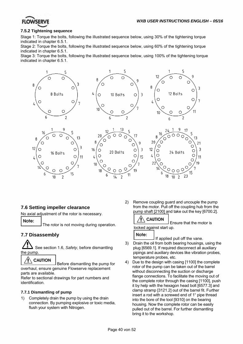
WXB USER INSTRUCTIONS ENGLISH – 05/16
Page 40 von 52
7.5.2 Tightening sequence Stage 1: Torque the bolts, following the illustrated sequence below, using 30% of the tightening torque indicated in chapter 6.5.1. Stage 2: Torque the bolts, following the illustrated sequence below, using 60% of the tightening torque indicated in chapter 6.5.1. Stage 3: Torque the bolts, following the illustrated sequence below, using 100% of the tightening torque indicated in chapter 6.5.1.
7.6 Setting impeller clearance No axial adjustment of the rotor is necessary.
The rotor is not moving during operation.
7.7 Disassembly
See section 1.6, Safety, before dismantling the pump.
Before dismantling the pump for overhaul, ensure genuine Flowserve replacement parts are available. Refer to sectional drawings for part numbers and identification.
7.7.1 Dismantling of pump 1) Completely drain the pump by using the drain
connection. By pumping explosive or toxic media, flush your system with Nitrogen.
2) Remove coupling guard and uncouple the pump from the motor. Pull off the coupling hub from the pump shaft [2100] and take out the key [6700.2].
Ensure that the motor is locked against start up.
If applied pull off the vane. 3) Drain the oil from both bearing housings, using the
plug [6569.1]. If required disconnect all auxiliary pipings and auxiliary devices like vibration probes, temperature probes, etc.
4) Due to the design with casing [1100] the complete rotor of the pump can be taken out of the barrel without disconnecting the suction or discharge flange connections. To facilitate the moving out of the complete rotor through the casing [1100], push it by help with the hexagon head bolt [6577.3] and clamp stramp [3121.2] out of the barrel fit. Further insert a rod with a screwed end of 1“ pipe thread into the bore of the tool [9310] on the bearing housing. Now the complete rotor can be easily pulled out of the barrel. For further dismantling bring it to the workshop.

WXB USER INSTRUCTIONS ENGLISH – 05/16
Page 41 von 52
If a spare hydraulic cartridge is available, this can be inserted into the barrel, and the pump is back in service in a few hours. If the whole pump should be removed, proceed with step 5) and 6).
5) The pump has to be disconnected from suction and discharge pipe. The alignment of the pump and driver has to be checked and put it down in writing.
6) Unscrew the mounting screws of the pump on the base plate. If the discharge casing were placed on the base plate by taper pin, remove them too. Lift the pump to a clean area by crane or other lifting device where the pump can be disassembled.
7.7.2 Dismantling of the line bearing side 1) Loosen hexagon head bolt [6577.1] of both bearing
covers [3260.4] and [3260.3]. 2) Remove bearing cover [3260.1] together with
labyrinth ring [4330.3] and O-ring [4610.1] from the pump.
3) Unscrew hex nuts [6581.2] and remove carefully bearing housing [3200.2] and outer ring of radial roller bearing [3012] with the aid of a crane from the pump.
4) Now unscrew the shaft nut [2910.2] and pull off lockwasher [6541.2], washer [2905.2], bearing adaptor sleeve [2471.2], O-ring [4610.8], inner ring of radial roller bearing [3012], sleeve [2471.2] and O-ring [4610.8] from pump shaft.
5) Now remove bearing cover [3260.3], if necessary. Line bearing:
NU409 2WXB
NU411 3WXB
NU413 4WXB
NU413 6WXB
7.7.3 Dismantling of the thrust bearing side 1) Unscrew the mounting screw of fan case and
remove it. Unscrew the clamping screw of fan and pull it off from the pump shaft.
2) Loosen the hexagon head bolt [6577.1] from bearing cover [3260.1] and loosen the hexagon head bolt [6577.1] from bearing cover [3260.2].
3) Remove bearing cover [3260.1] together with labyrinth ring [4330.2] from the pump.
4) Unscrew hex nuts [6581.2] and remove carefully bearing housing [3200.1] together with the aid of a crane from the pump.
5) Now unscrew the shaft nut [2910.1] and pull off lockwasher [6541.1], washer [2905.1], the two thrust ball bearings [3013], bearing adaptor sleeve [2471.1] and the O-ring [4610.2] from pump shaft.
6) Now remove bearing cover [3260.2] ,if necessary. Thrust bearing:
7409 BGM 2WXB
7411 BGM 3WXB
7413 BCBM 4WXB
7413 BCBM 6WXB
7.7.4 Dismantling of mechanical seal 1) Secure the mechanical seal by putting the
mounting plates into the groove of the shaft sleeve. Loose the grub screws, and disconnect the seal piping.
Drain the seal system, if applicable.
2) Loose hex nuts [6581.4] and pull off mechanical seal cartridge from the shaft. [2100]
7.7.5 Dismantling of hydraulic cartridge 1) Start at the line bearing side first following chapter
6.7.2 and 6.7.4. 2) As next step dismantle the thrust bearing side
following chapter 6.7.3 and 6.7.4. 3) The further dismantling has to be executed from
the thrust bearing side. Remove the o-ring [4610.4] and draw the stuffing box housing [4110] out of the discharge casing [1140].
4) Open the hex nuts [6581.1] of the studs [6572.1] and dismantle the pump stage by stage beginning at thrust bearing side.
5) First off all loose the socket head cup screws [6579.2] at the balancing drum [6230]. Then remove the clamping ring [1240], which is fixing the retaining ring [2530]. Now pull the balance drum [6230] from the shaft.
6) Now take the cup spring [4263] and the diffuser last stage [1410.2]out of the pump.
7) Start to dismantle the pump stage by stage. All parts of a stage (impeller [2200.1, 2200.2], diffusers [1410.2, 1410.1], the captive rings [2530.2] and stage casing [1160.1] have to be numbered to assure a reassemble in original sequence. The availability of a crane to secure the heavy parts would be very helpful, to avoid that they will fall on the shaft and damage or bend it.
8) Support the stage casing which is next to the discharge casing. Lift the discharge casing inclusive the bush [1600], which is fixed on it and also the diffuser of the last stage [1410.2] which is close in the casing. When necessary remove the bush from the discharge casing by loosen the socket head cap screws [6579.3]. By removing the o-ring [4610.6] out of the discharge casing with the help of a sharp tool also the diffuser can be removed.
9) Now remove the captive rings [2530.2] and draw off the impeller [2200.1] with the impeller wear ring [2300.1] from the shaft. Then take the key [6700.2] out of the groove and support the next stage casing [1160.1] which is closer to the suction casing and lift the last stage casing inclusive diffuser [1410.1] and casing wear ring from the pump.
WXB USER INSTRUCTIONS ENGLISH – 05/16
Page 42 von 52
10) As next step remove the interstage sleeve [2410] , the impeller [2200.1] with the impeller wear ring [2300.1] and the captive rings [2530.2] from the shaft. Now take again one key [6700.1] from the shaft and support the next stage casing. Remove the next stage casing still you have reached the suction casing [1130].
11) Remove the impeller first stage [2200.2] with the impeller wear ring [2300.2]. Then you can draw the shaft out off the suction casing. Pull out the suction casing [1130] from the casing [1100]. In the suction casing you can find the casing wear ring for the first stage [1500.2].
Pumps equipped with an inducer have a separate stage casing in front of 1st stage impeller.
7.8 Examination of parts 1) Check the casing wear ring and the impeller wear
ring against any wear. The diametrical clearance between the rings must not exceed twice the value in new condition.
2) Check all parts against corrosion and erosion. 3) Carefully check the coupling against any wear.
Rotate the angular contact bearing by hand, to check against abnormal sound. Check the bearing cages against any wear and the outer and inner race against running marks. Check the runout of the shafts. TIR (Total Indicated Runout) shall not exceed 0.04 mm/m (0.0005 in./ft) of length. TIR shall not exceed 0.08 mm (0.003 in.) over total shaft length.
7.8.1 Gap between particular parts
The diametrical gap between casing wear rings [1500.1, 1500.2] and impeller wear rings [2300.1, 2300.2] in assembled condition is:
Pump size Material Diametrical
gap diametrical gap between balance drum [6230] and
bush [1600] mm (in.)
2 WXB
Steel rings mm (in.) 0,4 (0.016)
0,3 (0.012) Stainless
rings mm (in.)
0,5 (0.019)
3 WXB
Steel rings mm (in.) 0,45 (0.017)
0,4 (0.016) Stainless
rings mm (in.)
0,55 (0.022)
4 WXB
Steel rings mm (in.) 0,45 (0.017)
0,35 (0.014) Stainless
rings mm (in.)
0,55 (0.022)
6 WXB
Steel rings mm (in.) 0,45 (0.017)
0,4 (0.016) Stainless
rings mm (in.)
0,55 (0.022)
The diametrical gap between diffuser [1410.1] or interstage bush [1610] and interstage sleeve [2410] is 0,25 mm (0.010 in.).
Gaps apply approximately for wear rings in assembled condition.
7.9 Assembly To assemble the pump consult the sectional drawings. Ensure threads, gasket and O-ring mating faces are clean. Apply thread sealant to non-face sealing pipe thread fittings.
7.9.1 Assembly of hydraulic cartridge
Be sure that the casing wear rings [1500.1,1500.2] are pressed in the stage casings [1160.1] respectively in the suction casing [1130], the impeller wear ring[2300.1, 2300.2] are pressed on the impellers [2200.1, 2200.2]. The rings should be fitted by tack welding or if necessary by grub screws. The same applies to the interstage bush [1610] in the diffusers [1410.1] and the packing seating ring [4133] in the stuffing box housing [4110]. 1) Assembling of the pump is easier in vertical
position (horizontal position is possible too). Use the reverse procedure as described in the chapter 6.7.5 Dismantling of hydraulic section.
2) Put the suction casing [1130] with the line bearing side down on a suitable support. Now insert the shaft in the suction casing screw it on a vertically positioned screw.
3) Put the key [6700.1] for the first stage in the shaft groove. Slide the first impeller [2200.2] from upwards carefully on the shaft till it touches the shoulder on the shaft. Adjust the shaft inclusive the impeller in reference to the suction casing by turning the shaft in the device. The right position is reached when the casing wear ring in the suction casing is even with the impeller wear ring of the first stage. This visual check is sufficient because the exact position of the shaft will be committed by assembling the thrust bearing. Put the captive rings [2530.2] in the shaft groove.
4) Now put from upwards the stage casing [1160.1] together with the tightly sitting diffuser [1410.1] , o-ring [4610.7], interstage bush [1610] and casing wear ring [1500.1] over the shaft [2100] and the impeller [2200.1] down to the suction casing [1130].
5) Slight the interstage sleeve [2410] on the shaft, taking care that it catches the key [6700.1]. When it isn’t the case all parts on the shaft would be displaced to the thrust bearing and after the pump is complete assembled it would not turn.
WXB USER INSTRUCTIONS ENGLISH – 05/16
Page 43 von 52
6) Be sure to follow the reverse sequence of all parts according to the one of dismantling. Watch the numbers designated at dismantling.
7) After mounting the diffuser of the last stage [1410.2], put on the cup springs [4263] and finally the discharge casing [1140] together with the bush [1600].
The bush [1600] is screwed with socket head cap screws [6579.3] to the discharge casing [1140]. Don´t forget the o-ring [4610.6]
8) Slight the balance drum [6230] on the shaft, so that the groove on it catches the key [6700.2]. Put the retaining ring [2530] in the groove on the shaft, slight the clamping ring [1240] over it and fix it with the socket head cap screws [6579.2].
9) Now assembly the line bearing and thrust bearing side including mechanical seals. Refer to chapter 6.9.2, 6.9.3 and 6.9.4.
10) Put on the o-rings [4610.9] to the discharge casing [1140], the o-rings [4610.10] to the last stage casing [1160.2] and the o-rings [4610.11] to the suction casing [1130].
11) Now the hydraulic cartridge is fully assembled and can be put into the casing [1100]. Use the clamp stramp [3121.1] with the help of the stud [6572.4] for final pulling off the hydraulic cartridge.
By putting the hydraulic cartridge into the barrel take care of the o-rings [4610.9, 4610.10, 4610.11].
14) Now tight crosswise the hex nuts [6581.1] of the studs [6572.1]. For final torque refer to section 6.5, Fastener torques.
The pump can also be assembled by putting the hydraulic parts piece per piece into the barrel.
7.9.2 Assembly of shaft seal Slide on the mechanical seal cartridge to the shaft [2100] and fix it to the stuffing box housing [4110] using hex nuts [6581.4] and studs [6572.2].
If the mechanical seal is equipped with a pumping device, pay attention to the correct sense of rotation of the same (line bearing side is different from thrust bearing side). 1) For assembly of shaft seal use the reverse
procedure as described in section 6.7.4 „Dismantling of mechanical seal“. Afterwards follow the instructions in section 6.9.3 „Assembly of the thrust bearing side“ or section 6.9.4 „Assembly of line bearing side“.
2) Replacing the mechanical seal extreme cleanness is recommended. The sealing faces of the mechanical seal must be free of scratches or other damages and have to be cleaned once again before assembly.
3) Before sliding the rotating parts on the shaft respectively on the shaft sleeve, the fits must be sufficiently lubricated with a molykote paste. Take care that the sealing faces remain clean and no grease touches them.
4) For those mechanical seals equipped with single springs, where a spring transmits the rotation from the shaft to the rotating sealing-ring, it must be considered that the spring must be wound up in the right direction (transmitting power the spring shall be contracted). In view from the spring-side to the sealing-faces and the shaft is turning clockwise the spring must be wound up counter clockwise and vice-versa.
5) If a mechanical seal with pump ring for medium circulation is used pay attention to the rotation of pump and pump ring.
6) At assembling the seal end plate and distance plate pay attention to the position of piping connections for injection or quench (refer to shaft seal drawing).
7) After assembly of complete mechanical seal unit on the shaft sleeve by paying attention to the correct axially positioning of rotating mechanical seal unit mount the complete mechanical seal unit on the stuffing box housing [4110] using nuts [6581.4] and studs [6572.2].
7.9.3 Assembly of the thrust bearing side 1) Use the reverse procedure to chapter 6.7.3,
Dismantling of the thrust bearing side. 2) Put the O-ring [4610.2] on the shaft. Slide the
sleeve [2471.1] on the shaft [2100] against the shoulder. Heat up the thrust ball bearings [3013] and slide them on to the shaft against the sleeve [2471.1].
All sealing faces must be free of damage, otherwise the lubrication oil would begin leaking excessively.
3) Before assembling all O-rings have to be checked or renewed. Special attention has to be drawn to the O-rings of labyrinth ring [4330.1] and [4330.2] at assembling into bearing cover. If one of the O-rings is stuck here the performance of the labyrinth-type seals will be reduced or they even will break in operation. If seal rings are assembled for item [4330.1] and [4330.2] pay attention to the correct assembly.
4) The washer [2905.1] has to be fitted correctly and fixed by lockwasher [6541.1] and shaft nut [2910.1].
5) Fixing the bearing side special attention has to be drawn to the cylindrical pin [6811] of stuffing box housing [4110] which has to grip into the flange of the bearing side.
7.9.4 Assembly of the line bearing side 1) Use the reverse procedure to chapter 6.7.2,
Dismantling of the line bearing side.
WXB USER INSTRUCTIONS ENGLISH – 05/16
Page 44 von 52
2) Put the O-ring [4610.8] on the shaft. Slide the sleeve [2471.2] on the shaft [2100] against the shoulder. Heat up the inner race of the roller bearing [3012] and push it on to the shaft against the sleeve [2471.2].
All sealing faces must be free of damage, otherwise the lubrication oil would begin leaking excessively.
3) Before assembling all O-rings have to be checked or renewed. Special attention has to be drawn to the O-rings of labyrinth ring [4330.1] and [4330.3] at assembling into bearing cover. If one of the O-rings is stuck here the performance of the labyrinth-type seals will be reduced or they even will break in operation. If seal rings are assembled for item [4330.1] and [4330.3] pay attention to the correct assembly. Attention: When the seal rings are equipped with a dust lip, the space between the sealing lip and the dust lip has to be filled with suitable grease. This results lower wearing and a higher tightness.
4) The washer [2905.2] has to be fitted correctly and fixed by lockwasher [6541.2] and shaft nut [2910.2].
5) Fixing the bearing side special attention has to be drawn to the cylindrical pin [6811] of stuffing box housing [4110] which has to grip into the flange of the bearing side.
7.9.5 Final assembly 1) Connect suction and discharge piping
Check alignment of flanges to avoid distortion based on too high flange forces.
2) See section 5.1, Precommissioning procedure for precommissioning.
8.0 AUXILIARIES
8.1 Seal and seal systems 8.1.1 Single Mechanical Seal with API–Plan 11+61 Refer to mechanical seal drawing and auxiliary piping drawing. The pump is equipped with a single mechanical seal. The cartridge design allows to change the mechanical seal without taking it apart. Try to turn the rotor by hand.If the rotor cannot be turned, the pump must be disassembled, refer to section 6.7.1 Dismantling WXB. Actions after start up: Check all connections to the seal gland and the mechanical seal itself against leakage. It is usual that at the seal faces a small leakage occurs after start
up, which decreases with the time of operation and should stop after the seal is run in. Check the temperature of the seal gland. I slight increase of temperature may be observed during the run in period. The mechanical seal is flushed by an API Plan 11 and the temperature at the seal gland should be max. 10 °C (18 °F) above the pumped liquid temperature, unless otherwise specified by mechanical seal supplier. In Plan 11, product is routed from the pump discharge via an orifice to the seal chamber to provide cooling for the seal and to vent air or vapors from the seal chamber. Fluid then flows from the seal cavity back into the process stream. API Plan 61 has tapped and plugged connections for the purchaser´s use. Typically this plan is used when the purchaser is to provide fluid (such as steam, gas, or water) to an external sealing device. Refer to the GA - drawing for the required quench medium, pressure and flow. Disassembly of the seal cartridge is only allowed by authorized personal. Contact Flowserve for any service of the mechanical seal. We recommend to have a spare cartridge seal on stock for easy replacement. 8.1.2 Dual Mechanical Seal unpressurized with API–Plan 23+72+76
Refer to mechanical seal drawing and auxiliary piping drawing. The pump is equipped with a dual mechanical seal. The cartridge design allows to change the mechanical seal without taking it apart. The seal cartridge consists of a contacting wet inner seal and a dry containment seal. A buffer gas is used to sweep inner seal leakage away from the outer seal into a collection system and/or provide dilution of the leakage, so that emissions from the containment seal are reduced. The plan 72 system is intended to function as follows: The barrier gas first flows through an isolation block valve and check valve provided by the purchaser. It then enters a system, usually mounted on a plate or panel, provided by the seal vendor. An inlet block valve on the panel is followed by a 10 µm (0.0004 in.) filter coalescer (if specified) to remove any particles and liquid that might be present. The gas then flows through a back pressure regulator (if specified) which is set at least 0.5 bar (7 psi) above atmospheric pressure. Next comes an orifice to provide flow regulation followed by a flow indicator to measure flow. The pressure indicator is used to ensure the pressure is not above the seal chamber pressure. The last elements on the panel are a check valve and block valve. Buffer gas is then routed to the seal
WXB USER INSTRUCTIONS ENGLISH – 05/16
Page 45 von 52
using tubing. A containment seal vent (CSV) and drain (CSD) are also located on the gland. The inner mechanical seal is flushed by an API Plan 23.
Try to turn the rotor by hand.If the rotor cannot be turned, the pump must be disassembled, refer to section 6.7.1 Dismantling WXB. Actions after start up: Check all connections to the seal gland and the mechanical seal itself against leakage. It is usual that at the seal faces a small leakage occurs after start up, which decreases with the time of operation and should stop after the seal is run in. Check the temperature of the seal gland. I slight increase of temperature may be observed during the run in period. The mechanical seal is flushed by an API Plan 23 and the temperature at the seal gland should be below the pumped liquid temperature (refer to mechanical seal drawing for temperature limit). Plan 23 is the plan of choice for all hot water services, and it is also disirable in many hydrocarbon and chemical services where it is necessary to cool the fluid establish the required margin between fluid vapor pressure (at the seal chamber temperature) and seal chamber pressure. In a Plan 23, the cooler only removes seal face-generated heat plus heat soak from the process. Plan 76 is suitable only for fluids, where no condensation of the inner seal leakage or from the collection system will occur. Leakage from the inner mechanical seal is restricted from escape by the containment seal and goes out the containment seal vent. An orifice in the outlet line of the collector restricts flow such that high leakage of the inner seal will cause a pressure increase and trigger the PSH set at a gauge pressure of 0.7 bar (10 psi). The block valve in the outlet serves to isolate the system for maintenance. It may also be used to test the inner seal by closing while the pump is in operation and noting the time/pressure buildup relationship in the collector. If specified, drain connection on the piping harness may be used to inject nitrogen or other gas for the purpose of testing the containment seal as well as for checking for any liquid buildup.
Disassembly of the seal cartridge is only allowed by authorized personal. Contact Flowserve for any service of the mechanical seal. We recommend to have a spare cartridge seal on stock for easy replacement.
8.1.3 Dual Mechanical Seal pressurized with API–Plan 53b+61
Refer to mechanical seal drawing and auxiliary piping drawing. The pump is equipped with a dual mechanical seal in face to back configuration, back to back configuration or face to face configuration.
Try to turn the rotor by hand.If the rotor cannot be turned, the pump must be disassembled, refer to section 6.7.1 Dismantling WXB. The mechanical seal requires no adjustment anymore. Check if the mounting plates are already swung out. Actions after start up: Check all connections to the seal gland and the mechanical seal itself against leakage. Check the temperature of the seal gland. I slight increase of temperature may be observed during the run in period. Plan 53 pressurized dual seal systems are used in services where no leakage to atmosphere can be tolerated. A Plan 53b system consists of dual mechanical seals with a liquid barrier fluid between them. The barrier fluid is contained in a seal pot and is pressurized by using a bladder type accumulator. Inner seal leakage will be barrier fluid leakage into the product. There will always be some leakage (max.5 ml/hour). The leakage rate is monitored by monitoring the seal pot level. The product must be able to accommodate a small amount of contamination from the barrier fluid. The seal pot pressure must be maintained at the proper level. If the seal pot pressure drops, the system will begin to operate like a Plan 52, or unpressurized dual seal, which does not offer the same level of sealing integrity. Specifically, the inner seal leakage direction will be reversed and the barrier fluid will, over time, become contaminated with the process fluid with the problems that result, including possible seal failure.
Fill the seal system with a suitable barrier buffer fluid (refer to lubrication table).
Open all necessary valves in the cooling and auxiliary piping and check the flow.
API Plan 61 has tapped and plugged connections for the purchaser´s use. Typically this plan is used when the purchaser is to provide fluid (such as steam, gas, or water) to an external sealing device.
WXB USER INSTRUCTIONS ENGLISH – 05/16
Page 46 von 52
Refer to the GA - drawing for the required flushing fluid, pressure and flow.
Disassembly of the seal cartridge is only allowed by authorized personal. Contact Flowserve for any service of the mechanical seal. We recommend to have a spare cartridge seal on stock for easy replacement.
8.1.4 API Plan K
Refer to auxiliary piping drawing. The pump is equipped with an API plan K, cooling to bearing housing with parallel flow to seal heat exchanger. Open all the valves in the cooling line before start up the pump.
Check cooling flow at the installed flow indicator. If required adjust flowrate with the flow control valve.
Refer to the GA - drawing for the required cooling flow and pressure.
8.2 Changing of mechanical seal 1) Completely drain the pump by using the drain
connection. By pumping explosive or toxic media, flush the system with Nitrogen.
2) Secure the mechanical seal by putting the mounting plates into the groove of the shaft sleeve. Loose the grub screws, and disconnect the seal piping.
Drain the seal system, if applicable.
3) For disassembly refer to section 6.7.2, 6.7.3, Dismantling of the line bearing side, Dismantling of the thrust bearing side.
4) For assembly refer to section 6.9.3, 6.9.4, Assembly of the thrust bearing side, Assembly of the line bearing side.
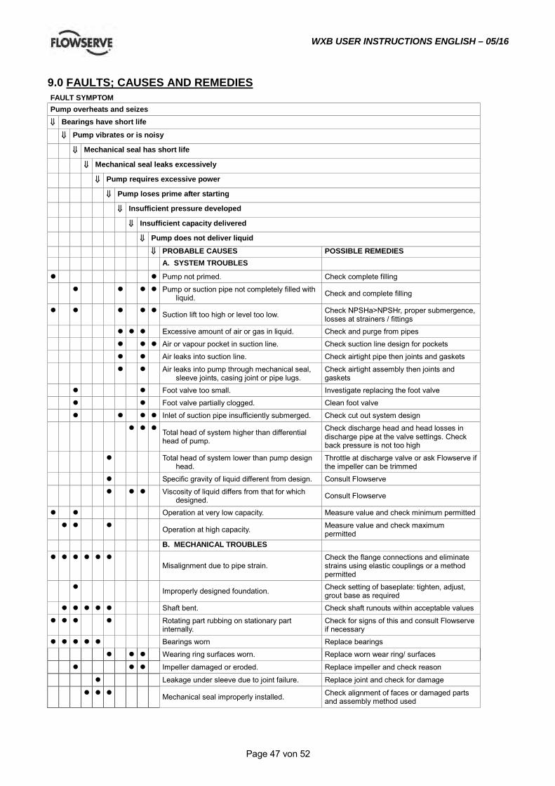
WXB USER INSTRUCTIONS ENGLISH – 05/16
Page 47 von 52
9.0 FAULTS; CAUSES AND REMEDIES
FAULT SYMPTOM Pump overheats and seizes
⇓⇓ Bearings have short life
⇓⇓ Pump vibrates or is noisy
⇓⇓ Mechanical seal has short life
⇓⇓ Mechanical seal leaks excessively
⇓⇓ Pump requires excessive power
⇓⇓ Pump loses prime after starting
⇓⇓ Insufficient pressure developed
⇓⇓ Insufficient capacity delivered
⇓⇓ Pump does not deliver liquid
⇓⇓ PROBABLE CAUSES POSSIBLE REMEDIES A. SYSTEM TROUBLES Pump not primed. Check complete filling Pump or suction pipe not completely filled with
liquid. Check and complete filling
Suction lift too high or level too low. Check NPSHa>NPSHr, proper submergence, losses at strainers / fittings
Excessive amount of air or gas in liquid. Check and purge from pipes Air or vapour pocket in suction line. Check suction line design for pockets Air leaks into suction line. Check airtight pipe then joints and gaskets Air leaks into pump through mechanical seal,
sleeve joints, casing joint or pipe lugs. Check airtight assembly then joints and gaskets
Foot valve too small. Investigate replacing the foot valve Foot valve partially clogged. Clean foot valve Inlet of suction pipe insufficiently submerged. Check cut out system design Total head of system higher than differential
head of pump.
Check discharge head and head losses in discharge pipe at the valve settings. Check back pressure is not too high
Total head of system lower than pump design head.
Throttle at discharge valve or ask Flowserve if the impeller can be trimmed
Specific gravity of liquid different from design. Consult Flowserve Viscosity of liquid differs from that for which
designed. Consult Flowserve
Operation at very low capacity. Measure value and check minimum permitted Operation at high capacity. Measure value and check maximum
permitted B. MECHANICAL TROUBLES
Misalignment due to pipe strain. Check the flange connections and eliminate strains using elastic couplings or a method permitted
Improperly designed foundation. Check setting of baseplate: tighten, adjust, grout base as required
Shaft bent. Check shaft runouts within acceptable values Rotating part rubbing on stationary part
internally. Check for signs of this and consult Flowserve if necessary
Bearings worn Replace bearings Wearing ring surfaces worn. Replace worn wear ring/ surfaces
Impeller damaged or eroded. Replace impeller and check reason
Leakage under sleeve due to joint failure. Replace joint and check for damage
Mechanical seal improperly installed. Check alignment of faces or damaged parts and assembly method used
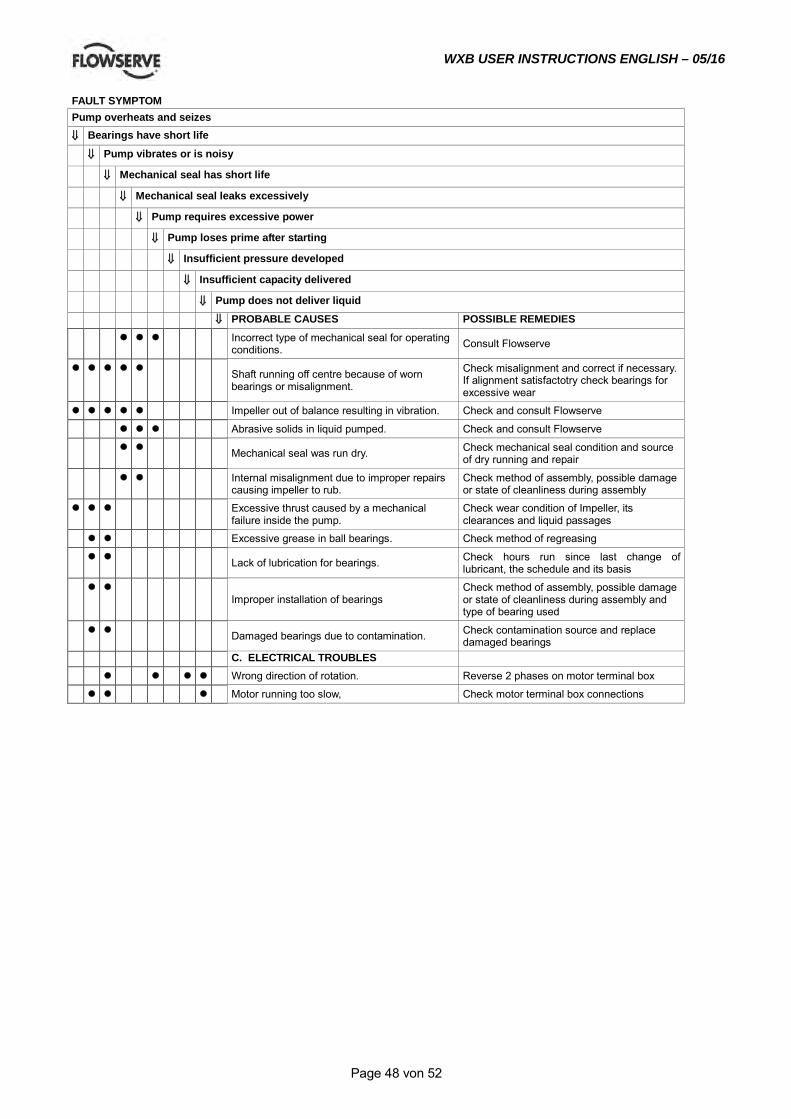
WXB USER INSTRUCTIONS ENGLISH – 05/16
Page 48 von 52
FAULT SYMPTOM Pump overheats and seizes
⇓⇓ Bearings have short life
⇓⇓ Pump vibrates or is noisy
⇓⇓ Mechanical seal has short life
⇓⇓ Mechanical seal leaks excessively
⇓⇓ Pump requires excessive power
⇓⇓ Pump loses prime after starting
⇓⇓ Insufficient pressure developed
⇓⇓ Insufficient capacity delivered
⇓⇓ Pump does not deliver liquid
⇓⇓ PROBABLE CAUSES POSSIBLE REMEDIES Incorrect type of mechanical seal for operating
conditions. Consult Flowserve
Shaft running off centre because of worn bearings or misalignment.
Check misalignment and correct if necessary. If alignment satisfactotry check bearings for excessive wear
Impeller out of balance resulting in vibration. Check and consult Flowserve
Abrasive solids in liquid pumped. Check and consult Flowserve
Mechanical seal was run dry. Check mechanical seal condition and source of dry running and repair
Internal misalignment due to improper repairs causing impeller to rub.
Check method of assembly, possible damage or state of cleanliness during assembly
Excessive thrust caused by a mechanical failure inside the pump.
Check wear condition of Impeller, its clearances and liquid passages
Excessive grease in ball bearings. Check method of regreasing
Lack of lubrication for bearings. Check hours run since last change of lubricant, the schedule and its basis
Improper installation of bearings
Check method of assembly, possible damage or state of cleanliness during assembly and type of bearing used
Damaged bearings due to contamination. Check contamination source and replace damaged bearings
C. ELECTRICAL TROUBLES
Wrong direction of rotation. Reverse 2 phases on motor terminal box
Motor running too slow, Check motor terminal box connections
WXB USER INSTRUCTIONS ENGLISH – 05/16
Page 49 von 52
10.0 CERTIFICATION Certificates determined from the contract requirements are provided with these instructions where applicable. Examples are certificates for CE marking, ATEX marking etc. If required, copies of other certificates sent separately to the Purchaser should be obtained from the Purchaser for retention with these User Instructions.
11.0 OTHER RELEVANT DOCUMENTATION AND MANUALS
11.1 Supplementary user instructions Supplementary instructions determined from the contract requirements for inclusion into user Instructions such as for a driver, instrumentation, controller, sub-driver, seals, sealant system, mounting component etc are included in the Data Book. If further copies of these are required they should be obtained from the supplier for retention with these user instructions. Where any pre-printed set of user instructions are used, and satisfactory quality can be maintained only by avoiding copying these, they are included at the end of these user instructions such as within a standard clear polymer software protection envelope.
11.2 Change notes If any changes, agreed with Flowserve, are made to the product after its supply, a record of the details should be maintained with these User Instructions.
11.3 Additional sources of information Reference 1: NPSH for Rotordynamic Pumps: a reference guide, Europump Guide No. 1, Europump & World Pumps, Elsevier Science, United Kingdom, 1999. Reference 2: Pump Handbook, 2nd edition, Igor J. Karassik et al, McGraw-Hill Inc., New York, 1993. Reference 3: ANSI/HI 1.1-1.5 Centrifugal Pumps - Nomenclature, Definitions, Application and Operation. Reference 4: ANSI B31.3 - Process Piping.
WXB USER INSTRUCTIONS ENGLISH – 05/16
Page 50 von 52
11.4 Abbreviations
Quantity ISO unit ISO unit abbreviation
Multiplication Factor 1 US unit US unit
Abbreviation
Area square metre square centimetre
m² cm²
10.764 0.155
square feet square inch
ft² in.²
Capacity or Flow rate
Cubic metre/hour m³/h 4.4033 US Gallons/
minute US gpm
Force Newton N 0.2248 pound.force lbf
Head metre m 3.28084 feet ft
Heat Energy kilojoule kJ 0.9478 British thermal unit Btu
Length metre
millimetre micrometre
m mm µm
3.28084 0.03937
0.00003937
feet inch inch
ft in. in.
Mass kilogram gram
kg g
2.20462 0.035274
pounds ounces
lb. oz.
Moment of Interia
kilogram square metre kg.m² 23.73 pounds
square feet lb.ft²
Noise 4 decibel dBA
Power kilowatt kW 1.34102 horsepower hp
Pressure 2 bar bar 14.5 pounds/in.² psi
Rotational Speed revs per minute r/min
Stress Newton/mm² N/mm² 145.0 pounds/in.² psi
Temperature degrees Celsius °C (1.8 x °C) + 32 degrees
Fahrenheit °F
Torque Newton.metre Nm 0.7376 pound.feet lbf.ft
Unbalance gram millimetre g.mm 0.001389 ounce-inch oz-in.
Velocity metre/second millimetre/second
m/s mm/s
3.28084 0.03937
feet/second inches/second
ft/sec in./sec
Vibration 3 millimetre/
second
mm/s
0.03937 inches/ second
in./sec
Viscosity square millimetre/ second or centiStoke cSt
Volume cubic metre litre
m³ l
264.2 33.81
US Gallons fluid ounce
US gal. Fl.oz.
1 multiply the ISO unit by the multiplication factor to obtain US units 2 where pressure is not stated to be absolute it is gauge 3 where not stated to be peak it is r.m.s. 4 sound pressure level LpA, re 1m - 20microPa, or sound power level LwA re 1 pW when sound power is applicable
WXB USER INSTRUCTIONS ENGLISH – 05/16
Page 51 von 52
AFTERMARKET DIRECTORY
OUR ADRESS
Flowserve (Austria) GmbH Tel: +43 / 2236 / 31530 Industriestraße B/6 Fax: +43 / 2236 / 33430 A-2345 Brunn/Geb., AUSTRIA Mail: [email protected]
MESSAGES CAN BE LEFT ALSO ON OUR ANSWERING MACHINE
IMPORTANT NOTES:
PLEASE NOTE, THAT WARRANTY EXPIRES: - USE OF NON GENUINE FLOWSERVE AUSTRIA PARTS FOR MAINTENANCE AND REPAIRS - NO USE OF OUR SERVICE PERSONAL IN CASE OF REPAIRS DURING WARRANTY PERIOD
RECOMMENDATION:
-PLEASE ASK FOR OUR SPECIAL RATES
- PLEASE ALSO ASK OUR SERVICE PERSONAL ABOUT REPAIRING AND SERVICING YOUR PUMPS AFTER THE WARRANTY PERIOD
Please quote your service: Name of Company: ………………………… Pumpdata: Contact person:.……………………….. Type: …………………. Telephone: …………….…………........... Serialno.: …….......……..... Fax: ...………………………………….... e-mail: ……………………………………… Country: ………………………………………
WXB USER INSTRUCTIONS ENGLISH – 05/16
Your Flowserve factory contacts: Flowserve (Austria) GmbH Industriestraße B6 2345 Brunn am Gebirge Austria
Telefon: +43 2236 31530 Fax: +43 2236 33430 E.mail: [email protected]
FLOWSERVE REGIONAL SALES OFFICES: USA and Canada Flowserve Corporation 5215 North O’Connor Blvd. Suite 2300 Irving, Texas 75039-5421, USA Telephone: +1 937 890 5839 Europe, Middle East, Africa Flowserve Corporation Parallelweg 13 4878 AH Etten-Leur The Netherlands Telephone: +31 76 502 8100 Latin America Flowserve Corporation Martín Rodriguez 4460 B1644CGN-Victoria-San Fernando Buenos Aires, Argentina Telephone: +54 11 4006 8700 Telefax: +54 11 4714 1610 Asia Pacific Flowserve Pte. Ltd. 10 Tuas Loop Singapore 637345 Telephone: +65 6771 0600 Telefax: +65 6862 2329
Recommended