Hindawi Publishing CorporationMathematical Problems in EngineeringVolume 2012, Article ID 848031, 21 pagesdoi:10.1155/2012/848031
Research ArticleWind-Induced Vibration Control ofDalian International Trade Mansion byTuned Liquid Dampers
Hong-Nan Li, Ting-Hua Yi, Qin-Yang Jing,Lin-Sheng Huo, and Guo-Xin Wang
Faculty of Infrastructure Engineering, Dalian University of Technology, Dalian 116023, China
Correspondence should be addressed to Ting-Hua Yi, [email protected]
Received 29 May 2011; Accepted 30 June 2011
Academic Editor: Xue-Jun Xie
Copyright q 2012 Hong-Nan Li et al. This is an open access article distributed under the CreativeCommons Attribution License, which permits unrestricted use, distribution, and reproduction inany medium, provided the original work is properly cited.
This paper focuses on the wind-induced vibration control of the Dalian international trade man-sion (DITM) by using the tuned liquid dampers (TLDs). To avoid the intensive computationallydemanding problem caused by tens of thousand of degrees of freedom (DOF) of the structure inthe numerical analysis, the three-dimension finite element model of the DITM is first simplifiedto the equivalent series multi-DOF system. The wind loading is subsequently simulated by theDavenport model according to the structural environmental condition where the actual samples ofwind speed are measured. Following that, the shallow- and deep-water wave theories are appliedto model the liquid sloshing inside TLDs, the tank sizing, and required water depth, and numbersof TLDs are given according to the numerical results of different cases. Comparisons betweenuncontrolled and controlled displacement and acceleration responses of the DITM under windforces show that the designed shallow tank has higher efficiency than the deep one, which caneffectively reduce the structural response amplitudes and enhance the comfortableness of themansion. The preliminary TLD design procedure presented in this paper could be applied as areference to the analysis and design of the wind-induced vibration for high-rise buildings usingthe TLD.
1. Introduction
In recent years, the newly developed construction technologies toward lighter and strongermaterials have facilitated the realization of more and more high-rise buildings in urbanareas where space usage is demanding [1]. This kind of structures have, in general, lowfrequencies and damping ratios associated with their fundamental oscillation modes, andwhen subjected to dynamic loadings, they may experience large amplitudes of bending andtorsional oscillation. Especially, if a high-rise building was built in a wind prone area, the
2 Mathematical Problems in Engineering
building would experience large deflection due tomeanwind and considerable vibration dueto aerodynamic effects. Serious vibrations may cause fatigue damage in structural members,and thereby increasing the maintenance cost of the building. In addition, the excessiveacceleration magnification will also frequently cause occupants’ discomfort [2, 3].
The suppression of these oscillations has become one of the major concerns to civilengineers. A number of methods exist for improving the performance of existing structuresto meet the requirements. Strengthening of the buildings or the installation of a base isolationsystem is complicated, difficult, and expensive. Therefore, incorporating control devices suchas the active and passive tuned mass dampers (AMD and TMD) [4, 5], tuned liquid dampers(TLD) [6, 7], and tuned liquid column dampers (TLCD) [8, 9] have been proposed tomitigateexcessive oscillations. Among many varieties of control devices, the TLD is a good candidate.A TLD consists of one or multiple rigid tanks, partially filled with a liquid (usually water),which is typically located near the top of a building. As the buildingmoves in the severe windor earthquake attack, the fluid contained within the tank begins to slosh. The fluid therebyabsorbs vibrational energy from the structure and transforms it into kinetic and potentialenergy of the sloshing fluid. The sloshing energy is subsequently dissipated through thefluid’s viscosity, or drag produced by flow dampening devices such as baffles, poles, netsor screens [10]. This kind of device is particularly well suited for tall buildings, since theyusually contain water storage for potable or emergency use. With the already available waterutilized and proper modifications to the existing storage tanks, a TLD can be formed withoutintroducing an unnecessarily large additional mass and only require very low maintenanceand operating cost. Furthermore, its natural frequency and damping characteristics can bemodified easily by changing the geometry of the tank, the depth of the liquid layer, and theproperties of the contained liquid [11].
Since TLD was first proposed by Bauer [12] for suppressing horizontal vibrationof building structures, many experimental and numerical research studies were done overthe past few years to illustrate the effectiveness of a TLD as a vibration-control devicefor structures subjected to both harmonic and broad-band excitations. Soong and Dargushproposed the use of a single TLD with a rectangular plan in control of vibration modesalong orthogonal two directions [13]. Zhang et al. proposed a liquid damper that canreduce bidirectional response using crossed tube-like liquid container [14]. Tamura et al.reported vibration control effect of cylindrical TSDs obtained for both orthogonal axes ofthe building plan based on measurement of acceleration response [15]. Research [16] hasbeen done to study the application of rectangular liquid dampers to reduce the vibrationof multidegree of freedom structures. Multiple tuned liquid dampers, which consist of anumber of tuned liquid dampers whose natural frequencies are distributed over a certainrange around the fundamental natural frequency of the structure, were suggested Fujino etal. [17] who referred to the idea of multiple tuned mass dampers [18] for more effectivelysuppressing dynamic responses, because the modal frequency of structure is not uncertain inpractice. Very recently, Samanta and Banerji [19] investigated a modified TLD configurationto improve the effectiveness of TLDs.
This paper presents a practical example for the effectiveness and feasibility of usingTLDs on the Dalian international trade mansion (DITM), a super high-rise RC structure,to control wind-induced vibration. The preliminary design procedure for initial TLD sizingdesign for a high-rise building is summarized and outlined, which could be applied as areference to the analysis and design of the wind-induced vibration for high-rise buildingsusing the TLDs.
Mathematical Problems in Engineering 3
Figure 1: Dalian international trade mansion.
2. Analytical Model
2.1. Mansion Outline
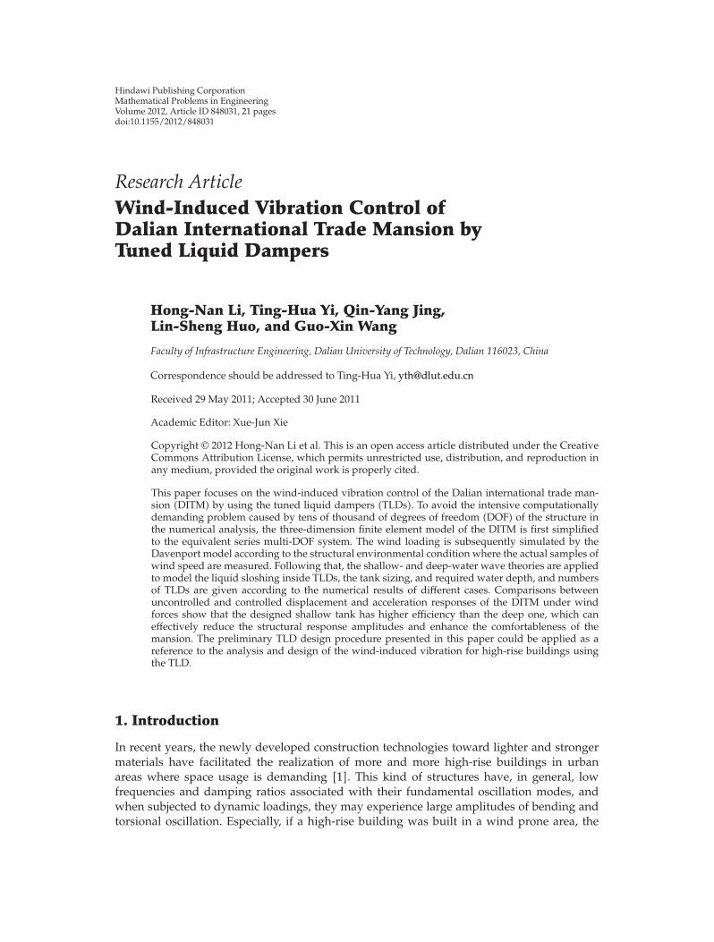
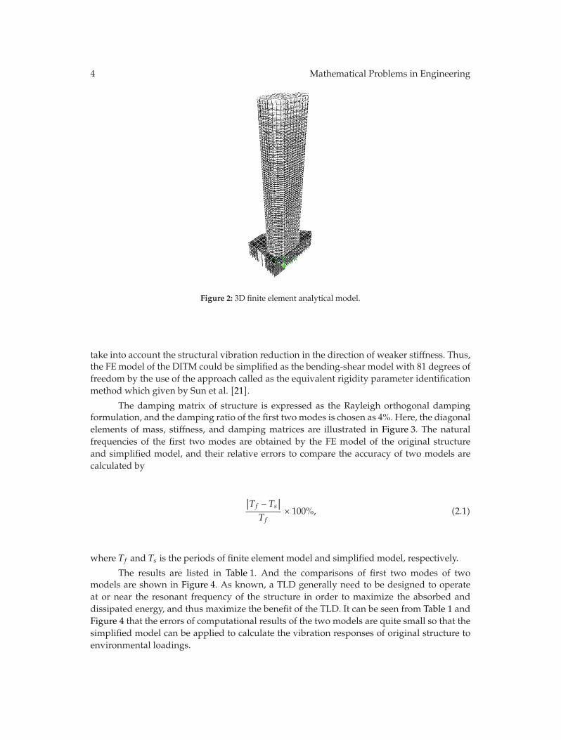
The DITM is being built in the center of Dalian city of China, which is of 81 stories (includingone-story basement) with the size of 339m high and 77.7m long in the east-west directionand 44m wide in south-north direction. The total building area is 290,000.00m2. The DITMis the highest building in the northeast of China (shown in Figure 1) [20]. Since the basicwind pressure in the Dalian region is 0.75KN/m2 and the mansion is slender, that is, theratio of height over width is 6.7, it is relatively more flexible to large wind-vibration actionin the horizontal direction. Consequently, the water tanks in the building will be designed asthe turned liquid dampers to reduce its horizontal displacement and acceleration. Figure 2shows the 3D finite element (FE) analytical model and the ichnography of the top story. Theoverall model has 34,308 node elements, 34,791 frame elements, and 29,071 shell elements,considering 36 section types and 11 materials’ properties.
2.2. Simplified Model
As known, due to inherent nonlinear liquid damping, iteration is generally required in orderto obtain the dynamic response of TLD-structure systems. It is no doubt that a solutionscheme resorting to iteration requires a great deal of computational effort in searching foroptimal parameters of dampers numerically. It would be quite a time-consuming task tocarry out a detailed design of the damper. On the other hand, for a large-scale complicatedstructure like the DITM, whose three-dimension finite element (FE) model may have tensof thousand of DOFs, to facilitate design of the TLDs, a systematic and efficient approach isneeded to solve such a computationally demanding problem. Considering that the structuralstiffness of the structure in two horizontal directions is obviously different, it could mainly
4 Mathematical Problems in Engineering
Figure 2: 3D finite element analytical model.
take into account the structural vibration reduction in the direction of weaker stiffness. Thus,the FE model of the DITM could be simplified as the bending-shear model with 81 degrees offreedom by the use of the approach called as the equivalent rigidity parameter identificationmethod which given by Sun et al. [21].
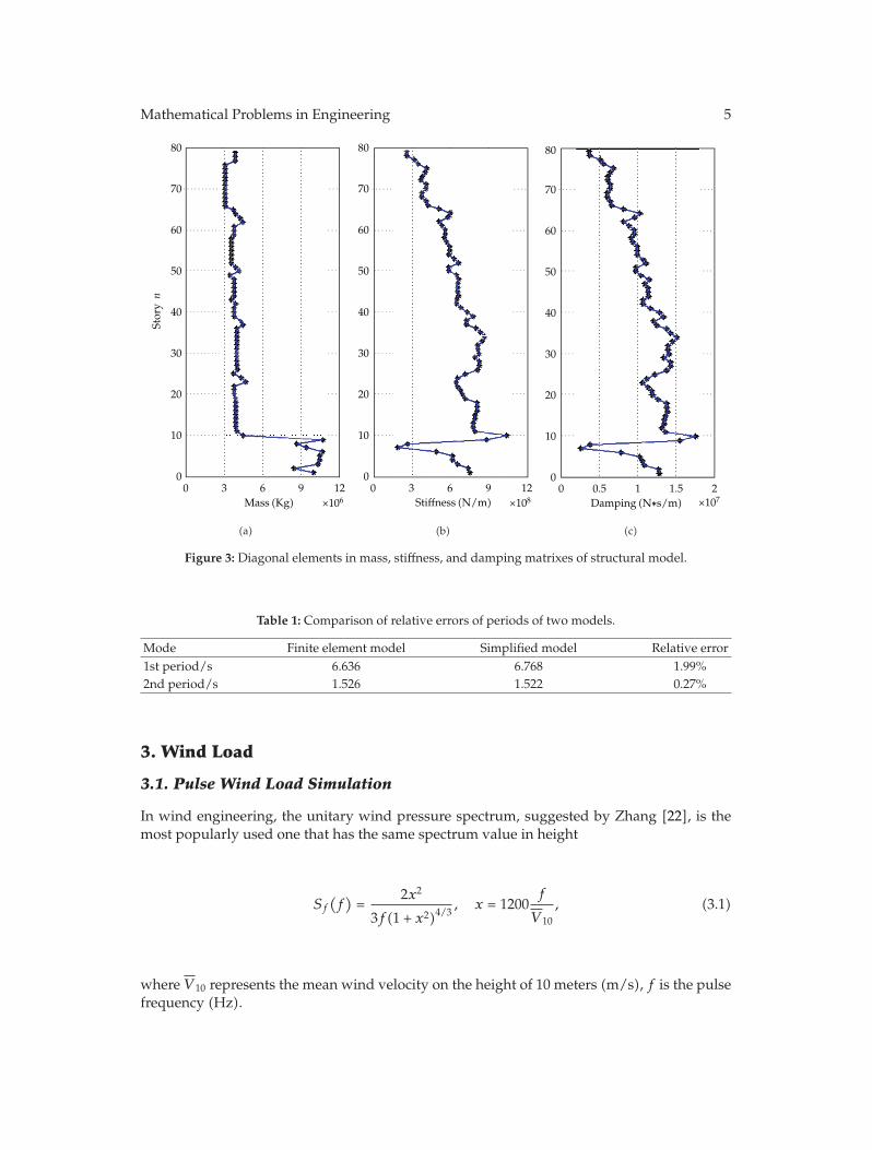
The damping matrix of structure is expressed as the Rayleigh orthogonal dampingformulation, and the damping ratio of the first twomodes is chosen as 4%. Here, the diagonalelements of mass, stiffness, and damping matrices are illustrated in Figure 3. The naturalfrequencies of the first two modes are obtained by the FE model of the original structureand simplified model, and their relative errors to compare the accuracy of two models arecalculated by
∣∣Tf − Ts
∣∣
Tf× 100%, (2.1)
where Tf and Ts is the periods of finite element model and simplified model, respectively.
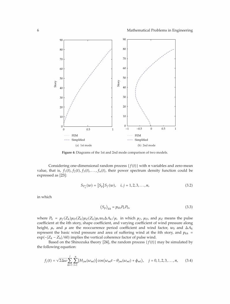
The results are listed in Table 1. And the comparisons of first two modes of twomodels are shown in Figure 4. As known, a TLD generally need to be designed to operateat or near the resonant frequency of the structure in order to maximize the absorbed anddissipated energy, and thus maximize the benefit of the TLD. It can be seen from Table 1 andFigure 4 that the errors of computational results of the two models are quite small so that thesimplified model can be applied to calculate the vibration responses of original structure toenvironmental loadings.
Mathematical Problems in Engineering 5
80
70
60
50
40
30
20
10
00 3 6 9 12
×106Mass (Kg)
Storyn
(a)
80
70
60
50
40
30
20
10
00 3 6 9 12
×108Stiffness (N/m)
(b)
80
70
60
50
40
30
20
10
00
×1070.5 1 21.5Damping (N∗s/m)
(c)
Figure 3: Diagonal elements in mass, stiffness, and damping matrixes of structural model.
Table 1: Comparison of relative errors of periods of two models.
Mode Finite element model Simplified model Relative error1st period/s 6.636 6.768 1.99%2nd period/s 1.526 1.522 0.27%
3. Wind Load
3.1. Pulse Wind Load Simulation
In wind engineering, the unitary wind pressure spectrum, suggested by Zhang [22], is themost popularly used one that has the same spectrum value in height
Sf
(
f)
=2x2
3f(1 + x2)4/3, x = 1200
f
V 10
, (3.1)
where V 10 represents the mean wind velocity on the height of 10 meters (m/s), f is the pulsefrequency (Hz).
6 Mathematical Problems in Engineering
90
80
70
60
50
40
30
20
10
00
FEMSimplified
0.5 1
Story
(a) 1st mode
90
80
70
60
50
40
30
20
10
0
Story
−1 −0.5 0 0.5 1
FEMSimplified
(b) 2nd mode
Figure 4: Diagrams of the 1st and 2nd mode comparison of two models.
Considering one-dimensional random process {f(t)} with n variables and zero-meanvalue, that is, f1(t), f2(t), f3(t), . . . , fn(t), their power spectrum density function could beexpressed as [23]:
SF∗ij(w) =
[
Sp
]
Sf(w), i, j = 1, 2, 3, . . . , n, (3.2)
in which
(
Sp
)
kh= pkhPkPh, (3.3)
where Pk = μf(Zk)μD(Zk)μZ(Zk)μrw0ΔAk/μ, in which μf , μD, and μZ means the pulsecoefficient at the kth story, shape coefficient, and varying coefficient of wind pressure alongheight, μr and μ are the reoccurrence period coefficient and wind factor, w0 and ΔAk
represent the basic wind pressure and area of suffering wind at the kth story, and pkh =exp(−|Zk − Zh|/60) implies the vertical coherence factor of pulse wind.
Based on the Shinozuka theory [24], the random process {f(t)} may be simulated bythe following equation:
fj(t) =√2Δω
j∑
m=1
n∑
l=1
∣∣Hjm(ωml)
∣∣ cos
(
ωmlt − θjm(ωml) + φml
)
, j = 0, 1, 2, 3, . . . , n, (3.4)
Mathematical Problems in Engineering 7
where j is the maximum positive integer, Δω means the frequency increment calculated byΔω = (ωb−ωa)/N in whichωa andωb are the starting and ending frequency, φml denotes therandom phase distributed in the range of (0, 2π),Hjm(ωml) implies the element in the matrix,H(ω) and H(ω) is the Cholesky decomposition of matrix S(ω); that is,
S(ω) = H(ω)H∗(ω)T , (3.5)
in which, ωml = (l − 1)Δω +(m
n
)
Δω, θjm(ωl) is given by
θjm(ωl) = tan−1(
Im⌊
Hjm(ωl)⌋
Re[
Hjm(ωl)]
)
. (3.6)
Based on the central limitation theorem, the random process {fj(t)} will graduallytend to be the Gauss process as N → ∞. And the time interval Δt should meet therequirement of Δt ≤ 2π/2ωb in order to avoid the sample superposition according to thesampling theory.
As mentioned above, the good samples can be acquired from (3.4) only if S(ω) isknown, andN,ωb andΔt are properly selected. However, since this method would consumemore time and energy while calculating, the Fast Fourier Transform algorithm (FFT) isintroduced in (3.4) to obtain higher efficiency:
fj(
pΔt)
= Re
{j∑
m=1
hjm
(
qΔt)
exp[
i
(mΔω
n
)(
pΔt)]}
,
p = 0, 1, 2, 3, 4, . . . , 2N × n − 1; j = 0, 1, 2, 3, 4, . . . , n,
(3.7)
where
hjm
(
qΔt)
=2N−1∑
l=0
gjm(lΔω) exp[
iπdq
N
]
, q = 0, 1, 2, 3, 4, . . . , n − 1, (3.8)
in which
gjm(lΔω) =
⎧
⎪⎨
⎪⎩
√2ΔωHjm
(
lΔω +mΔω
n
)
exp(
iφml
)
, 0 ≤ l < N,
0, N ≤ l < 2N.(3.9)
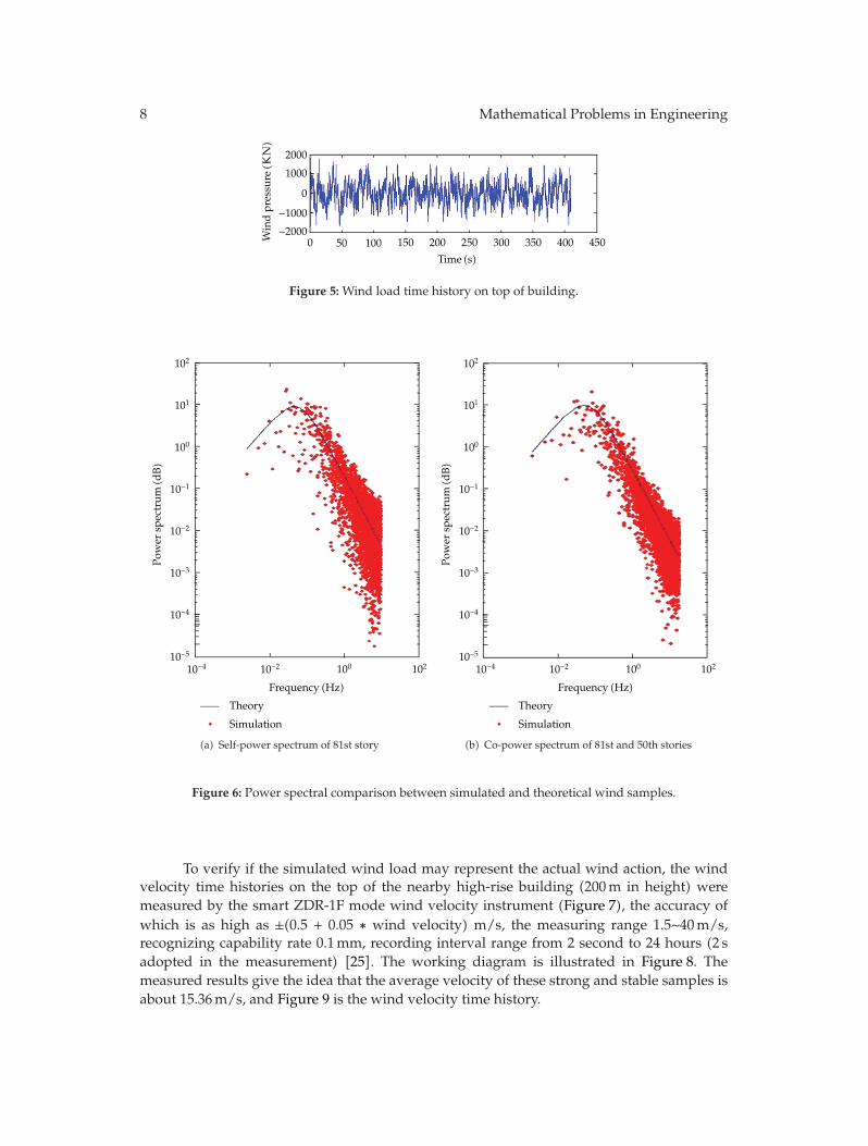
It can be known from (3.8) and (3.9) that hjm(qΔt) is the inverse Fourier transformof gjm(lΔω), which is calculated by FFT. Thus, 81 samples of wind load are calculated byselecting N = 8192,Δt = 0.05, ωa = 0, and ωb = 60. The wind pressure time history ofthese samples acting on the top of structure is illustrated in Figure 5 and its theoretical andsimulated spectra are shown in Figure 6. It can be seen from these figures that the simulatedresults are perfect.
8 Mathematical Problems in Engineering
2000
1000
0
−1000−2000
500 150 200 250 300 350 400 450
Time (s)(
)Windpressu
reKN
100
Figure 5: Wind load time history on top of building.
102
101
100
10−1
10−2
10−3
10−4
10−510210010−210−4
Frequency (Hz)
Theory
Simulation
Power
spectrum
(dB)
(a) Self-power spectrum of 81st story
102
101
100
10−1
10−2
10−3
10−4
10−510210010−210−4
Frequency (Hz)
Theory
Simulation
Power
spectrum
(dB)
(b) Co-power spectrum of 81st and 50th stories
Figure 6: Power spectral comparison between simulated and theoretical wind samples.
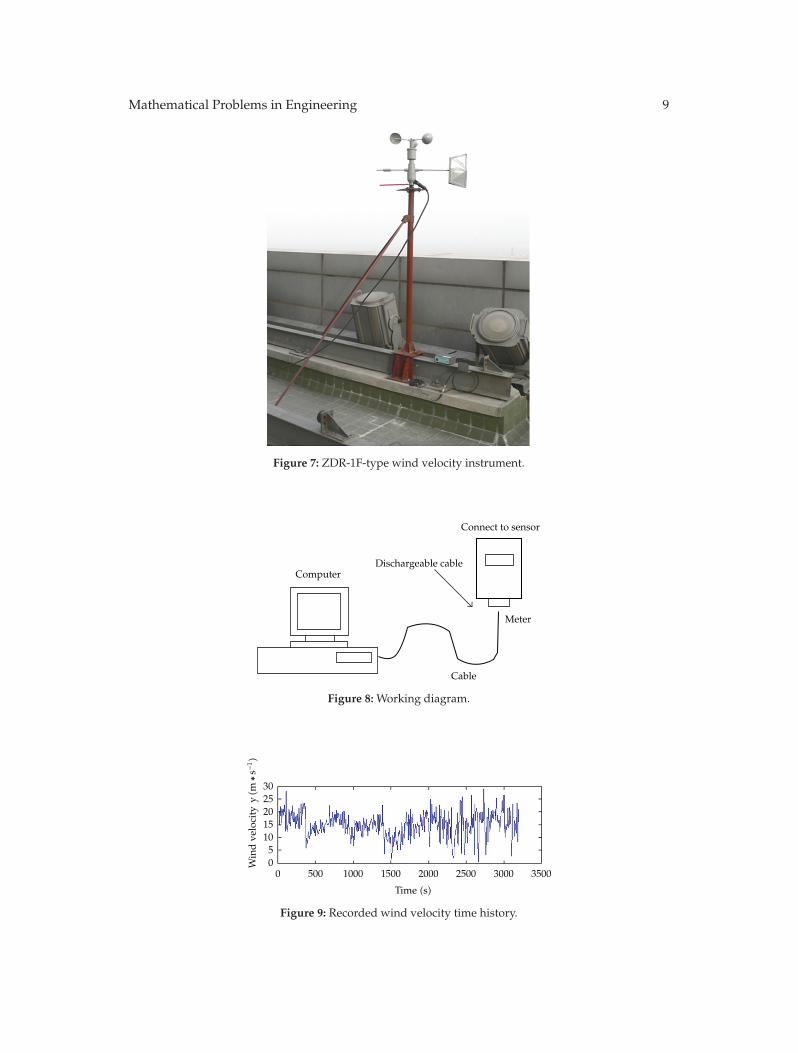
To verify if the simulated wind load may represent the actual wind action, the windvelocity time histories on the top of the nearby high-rise building (200m in height) weremeasured by the smart ZDR-1F mode wind velocity instrument (Figure 7), the accuracy ofwhich is as high as ±(0.5 + 0.05 ∗ wind velocity) m/s, the measuring range 1.5∼40m/s,recognizing capability rate 0.1mm, recording interval range from 2 second to 24 hours (2 sadopted in the measurement) [25]. The working diagram is illustrated in Figure 8. Themeasured results give the idea that the average velocity of these strong and stable samples isabout 15.36m/s, and Figure 9 is the wind velocity time history.
Mathematical Problems in Engineering 9
Figure 7: ZDR-1F-type wind velocity instrument.
ComputerDischargeable cable
Connect to sensor
Meter
Cable
Figure 8: Working diagram.
3025
1510500 500 1000 1500 2000 2500 3000 3500
20
Windve
locity
y(m
∗−1)
s
Time (s)
Figure 9: Recorded wind velocity time history.
10 Mathematical Problems in Engineering
100
10−2
10−4
10−6
10−10
10−8
Power
spectrum
(dB)
10010−1 10110−210−3
Frequency (Hz)
Simulat
Recorded
ed
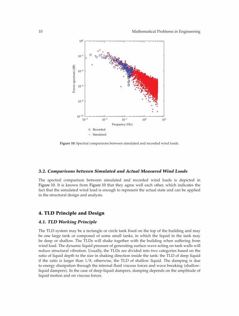
Figure 10: Spectral comparisons between simulated and recorded wind loads.
3.2. Comparisons between Simulated and Actual Measured Wind Loads
The spectral comparison between simulated and recorded wind loads is depicted inFigure 10. It is known from Figure 10 that they agree well each other, which indicates thefact that the simulated wind load is enough to represent the actual state and can be appliedin the structural design and analysis.
4. TLD Principle and Design
4.1. TLD Working Principle
The TLD system may be a rectangle or circle tank fixed on the top of the building and maybe one large tank or composed of some small tanks, in which the liquid in the tank maybe deep or shallow. The TLDs will shake together with the building when suffering fromwind load. The dynamic liquid pressure of generating surface wave acting on tank walls willreduce structural vibration. Usually, the TLDs are divided into two categories based on theratio of liquid depth to the size in shaking direction inside the tank: the TLD of deep liquidif the ratio is larger than 1/8, otherwise, the TLD of shallow liquid. The damping is dueto energy dissipation through the internal fluid viscous forces and wave breaking (shallow-liquid dampers). In the case of deep-liquid dampers, damping depends on the amplitude ofliquid motion and on viscous forces.
Mathematical Problems in Engineering 11
h
hb
y
x
a a
x
ηO
Free surface
Boundarylayer
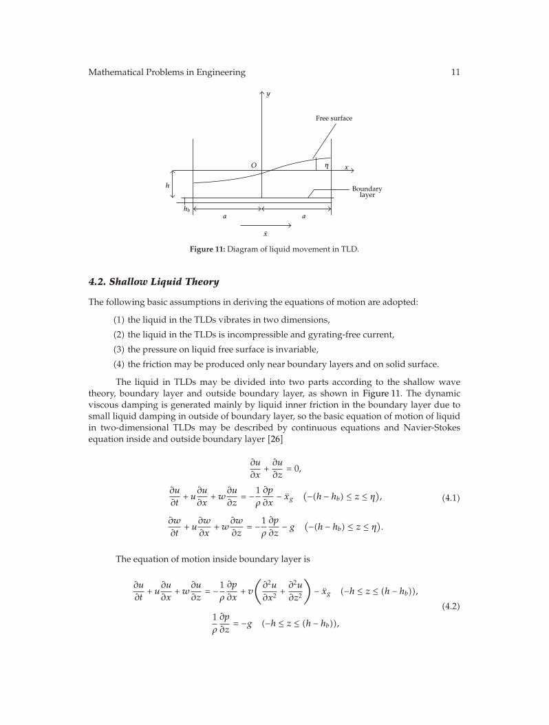
Figure 11: Diagram of liquid movement in TLD.
4.2. Shallow Liquid Theory
The following basic assumptions in deriving the equations of motion are adopted:
(1) the liquid in the TLDs vibrates in two dimensions,
(2) the liquid in the TLDs is incompressible and gyrating-free current,
(3) the pressure on liquid free surface is invariable,
(4) the friction may be produced only near boundary layers and on solid surface.
The liquid in TLDs may be divided into two parts according to the shallow wavetheory, boundary layer and outside boundary layer, as shown in Figure 11. The dynamicviscous damping is generated mainly by liquid inner friction in the boundary layer due tosmall liquid damping in outside of boundary layer, so the basic equation of motion of liquidin two-dimensional TLDs may be described by continuous equations and Navier-Stokesequation inside and outside boundary layer [26]
∂u
∂x+∂u
∂z= 0,
∂u
∂t+ u
∂u
∂x+w
∂u
∂z= −1
ρ
∂p
∂x− xg
(−(h − hb) ≤ z ≤ η)
,
∂w
∂t+ u
∂w
∂x+w
∂w
∂z= −1
ρ
∂p
∂z− g
(−(h − hb) ≤ z ≤ η)
.
(4.1)
The equation of motion inside boundary layer is
∂u
∂t+ u
∂u
∂x+w
∂u
∂z= −1
ρ
∂p
∂x+ v
(
∂2u
∂x2+∂2u
∂z2
)
− xg (−h ≤ z ≤ (h − hb)),
1ρ
∂p
∂z= −g (−h ≤ z ≤ (h − hb)),
(4.2)
12 Mathematical Problems in Engineering
where u and w are the velocities of liquid mass in x and z directions, p means the liquidinner pressure, hb denotes the thickness of boundary layer, ρ implies the liquid density, vliquid dynamic viscosity factor, xg represents the acceleration of tank movement, and g is thegravity acceleration.
The boundary conditions are
u = 0, (x = ±a),w = 0, (z = −h),
w =∂η
∂t+ u
∂η
∂x,
(
z = η)
,
p = p0 = const,(
z = η)
.
(4.3)
The liquid movement outside the boundary layer is treated as potential flow, velocitypotential function, Φ, of which could be supposed as follows:
Φ(x, z, t) = F(x, t) cosh[k(h + z)]. (4.4)
It is derived from potential function that
u =∂Φ∂x
=∂F
∂xcosh(k(h + z)),
w =∂Φ∂z
= kF sinh(k(h + z)).
(4.5)
Substituting (4.5) into (4.1) and (4.2), the basic equations are obtained after conversingby combing boundary condition(4.3)
∂η
∂t+ hσ
∂(
φu(
η))
∂x= 0,
∂
∂tu(
η)
+(
1 − T2H
)
u(
η) ∂
∂xu(
η)
+ g∂η
∂x+ ghσφ
∂2η
∂x2
∂η
∂x= −λu(η) − xS,
(4.6)
where
σ =tanh(kh)
kh,
φ =tanh
(
k(
h + η))
tanh(kh),
TH = tanh[
k(
h + η)]
,
λ =(
1n + h
)83π
√ωv
(
1 +(2hb
)
+ S
)
,
(4.7)
Mathematical Problems in Engineering 13
which could be called as viscous coefficient. in which k is the wave number taken as π/2,b means the tank width and S implies the viscous influencing factor on the liquid surfaceusually taken as 0∼2.
To make each parameter dimensionless, it is expressed as
x′ =x
a, z′ =
z
h, η′ =
η
h, ε =
h
a, u′ =
u
C0, t′ =
t
t0, k′ = ka, x′
S =t20axS, (4.8)
in which, C0 =√
gh, t0 = a/C0.Equations (4.6) are discredited along the vibration direction of tank as follows:
dη′i
dt′=
σ
Δx′(
φiu′i − φi+1u
′i+1
)
(i = 1 ∼ n − 1),
dη′0
dt′= − 2σ
Δx′φ1u′1,
dη′n
dt′=
2σΔx′φnu
′n,
du′
dt′=
1Δx′(
η′i−1 − η′
i +Hi(Ki−1 −Ki) + Ci(Ii−1 − Ii)) − λ′iu
′i − x′
S (i = 1 ∼ n),
(4.9)
where
Δx′ =2n,
φi =tanh
(
k′ε(
1 +(
η′i−1 + η′
i
)
/2))
tanh(k′ε)(i = 1 ∼ n),
Hi =
(
1 − (φi tanh(k′ε))2)
2(i = 1 ∼ n),
Ki =
((
u′i + u′
i+1
)
2
)2
(i = 1 ∼ n − 1),
Ii =
(((
η′i+1 − η′
i−1)
/(2Δx′))2)
2(i = 1 ∼ n − 1),
λ′ =1
1 +(
η′i−1 + η′
i
)
/28
3πεC0
√ωv
(
1 +(2hb
)
+ S
)
.
(4.10)
14 Mathematical Problems in Engineering
It is suggested here that the n value may be taken as
n =π
(
2 arccos(√
(tanh(πε))/(2 tanh(πε/2)))) , (4.11)
and then dynamic liquid pressure can be expressed as follows:
FTLD =14MW
gh
a
((
η′n + 1
)2 − (η′0 + 1
)2)
, (4.12)
where MW = 2pabh represents liquid weight in the TLD.
4.3. TLD Design
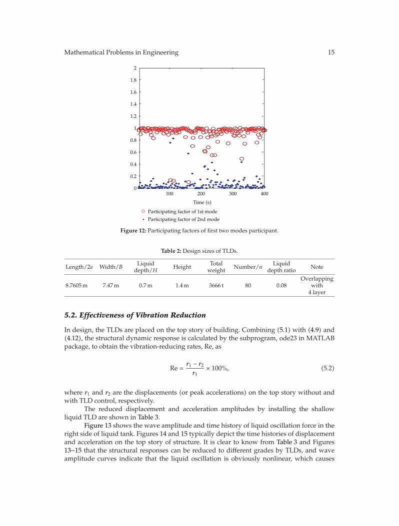
It is known that the average participating factor of the 1st mode in structural displacementresponse is about 92.07% and the 2nd mode is 6.67% by calculations. The two modalparticipating coefficients in the structural response are illustrated in Figure 12.
As mentioned above, the only first mode response is controlled by the TLDs in design,since it dominates the total structural response in the tall building. Then, the 1st oscillationfrequency of liquid in TLDs is tuned to the first modal frequency of structure according to theTLD tuning condition; that is,
ω1 =
√
πg
2atanh
(πh
2a
)
= 0.92836. (4.13)
Thus, the sizes of the TLDs, including the length (R) and depth (H), are designed aslisted in Table 2.
5. Calculation of Wind-Induced Structural Vibration Reduction
5.1. Equation of DITM for Structure-TLDs System
The equation of motion for the structure-TLDs system is
[M]{x} + [C]{x} + [K]{x} ={
f(t)} − [H]{FTLD}, (5.1)
where {x}, {x}, and {x} represent the structural displacement, velocity, and accelerationvectors, [M], [C], and [K] imply the structural mass, damping, and rigid matrices, {f(t)}denotes the pulse wind load vector acting on structure, {FTLD} means the control forcevector of TLDs, and [H] is the position matrix of TLDs in which its ith column vector{H}i = [0 · · · 0 1 0 · · · 0]T1×n (1 is in jth column) is that the ith group TLDs are installed onthe jth story.
Mathematical Problems in Engineering 15
2
1.8
1.6
1.4
1.2
1
0.8
0.6
0.4
0.2
0100 200 300 400
Time (s)
Participating factor of 1st mode
Participating factor of 2nd mode
Figure 12: Participating factors of first two modes participant.
Table 2: Design sizes of TLDs.
Length/2a Width/B Liquiddepth/H Height Total
weight Number/n Liquiddepth ratio Note
8.7605m 7.47m 0.7m 1.4m 3666 t 80 0.08Overlapping
with4 layer
5.2. Effectiveness of Vibration Reduction
In design, the TLDs are placed on the top story of building. Combining (5.1) with (4.9) and(4.12), the structural dynamic response is calculated by the subprogram, ode23 in MATLABpackage, to obtain the vibration-reducing rates, Re, as
Re =r1 − r2r1
× 100%, (5.2)
where r1 and r2 are the displacements (or peak accelerations) on the top story without andwith TLD control, respectively.
The reduced displacement and acceleration amplitudes by installing the shallowliquid TLD are shown in Table 3.
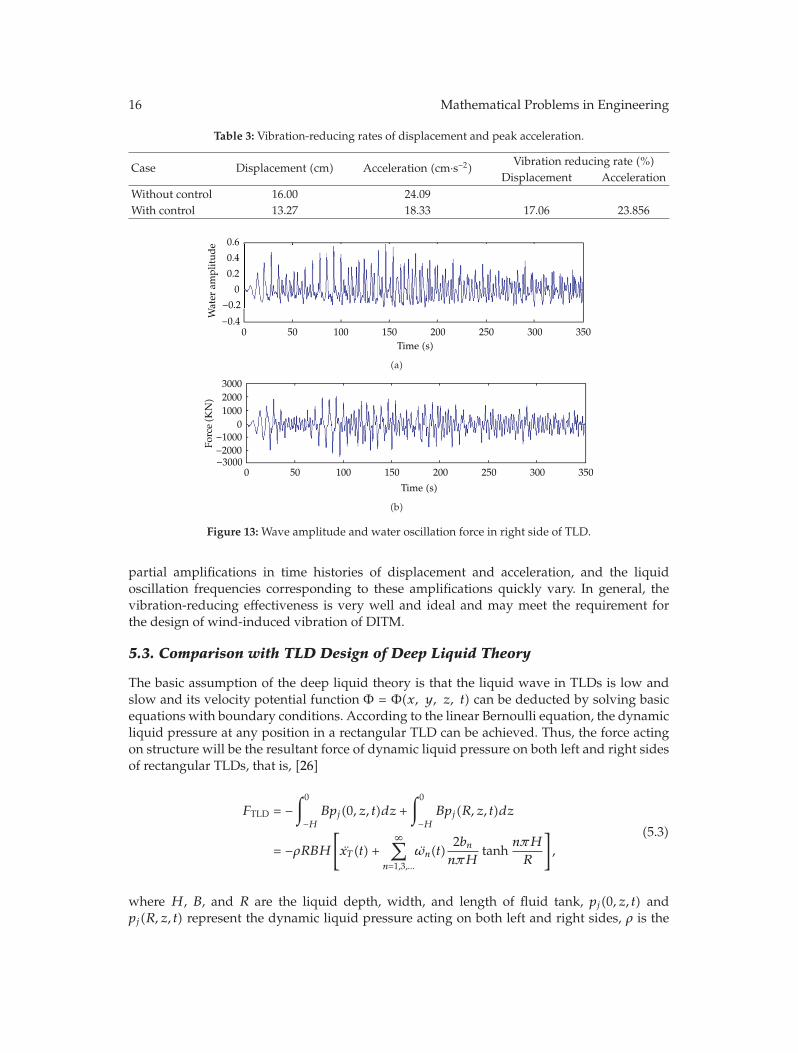
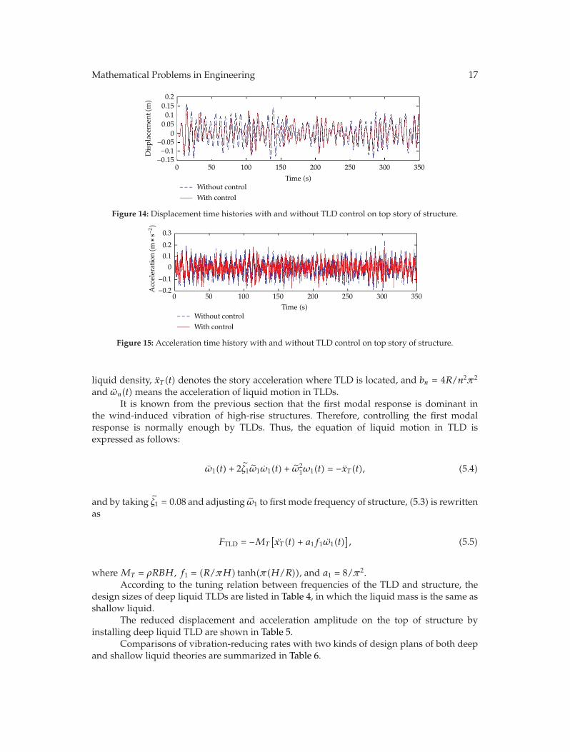
Figure 13 shows the wave amplitude and time history of liquid oscillation force in theright side of liquid tank. Figures 14 and 15 typically depict the time histories of displacementand acceleration on the top story of structure. It is clear to know from Table 3 and Figures13∼15 that the structural responses can be reduced to different grades by TLDs, and waveamplitude curves indicate that the liquid oscillation is obviously nonlinear, which causes
16 Mathematical Problems in Engineering
Table 3: Vibration-reducing rates of displacement and peak acceleration.
Case Displacement (cm) Acceleration (cm·s−2) Vibration reducing rate (%)Displacement Acceleration
Without control 16.00 24.09With control 13.27 18.33 17.06 23.856
0.6
0.4
0.2
0
−0.2−0.4
0 50 100 150 200 250 300 350
Water
amplitud
e
Time (s)
(a)
0 50 100 150 200 250 300 350
100020003000
0−1000−2000−3000
Force(K
N)
Time (s)
(b)
Figure 13: Wave amplitude and water oscillation force in right side of TLD.
partial amplifications in time histories of displacement and acceleration, and the liquidoscillation frequencies corresponding to these amplifications quickly vary. In general, thevibration-reducing effectiveness is very well and ideal and may meet the requirement forthe design of wind-induced vibration of DITM.
5.3. Comparison with TLD Design of Deep Liquid Theory
The basic assumption of the deep liquid theory is that the liquid wave in TLDs is low andslow and its velocity potential function Φ = Φ(x, y, z, t) can be deducted by solving basicequations with boundary conditions. According to the linear Bernoulli equation, the dynamicliquid pressure at any position in a rectangular TLD can be achieved. Thus, the force actingon structure will be the resultant force of dynamic liquid pressure on both left and right sidesof rectangular TLDs, that is, [26]
FTLD = −∫0
−HBpj(0, z, t)dz +
∫0
−HBpj(R, z, t)dz
= −ρRBH[
xT (t) +∞∑
n=1,3,...
ωn(t)2bnnπH
tanhnπH
R
]
,
(5.3)
where H, B, and R are the liquid depth, width, and length of fluid tank, pj(0, z, t) andpj(R, z, t) represent the dynamic liquid pressure acting on both left and right sides, ρ is the
Mathematical Problems in Engineering 17
0 50 100 150 200 250 300 350
0.20.150.10.05
0−0.05−0.1
− .0 15
Displacem
ent(m)
Without controlWith control
Time (s)
Figure 14: Displacement time histories with and without TLD control on top story of structure.
0 50 100 150 200 250 300 350
Without controlWith control
0.2
0.3
0.1
0
−0.2−0.1
Time (s)
Acceleration(m
∗−2)
s
Figure 15: Acceleration time history with and without TLD control on top story of structure.
liquid density, xT (t) denotes the story acceleration where TLD is located, and bn = 4R/n2π2
and ωn(t) means the acceleration of liquid motion in TLDs.It is known from the previous section that the first modal response is dominant in
the wind-induced vibration of high-rise structures. Therefore, controlling the first modalresponse is normally enough by TLDs. Thus, the equation of liquid motion in TLD isexpressed as follows:
ω1(t) + 2ζ1ω1ω1(t) + ω21ω1(t) = −xT (t), (5.4)
and by taking ζ1 = 0.08 and adjusting ω1 to first mode frequency of structure, (5.3) is rewrittenas
FTLD = −MT
[
xT (t) + a1f1ω1(t)]
, (5.5)
where MT = ρRBH, f1 = (R/πH) tanh(π(H/R)), and a1 = 8/π2.According to the tuning relation between frequencies of the TLD and structure, the
design sizes of deep liquid TLDs are listed in Table 4, in which the liquid mass is the same asshallow liquid.
The reduced displacement and acceleration amplitude on the top of structure byinstalling deep liquid TLD are shown in Table 5.
Comparisons of vibration-reducing rates with two kinds of design plans of both deepand shallow liquid theories are summarized in Table 6.
18 Mathematical Problems in Engineering
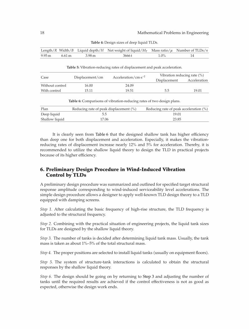
Table 4: Design sizes of deep liquid TLDs.
Length/R Width/B Liquid depth/H Net weight of liquid/MT Mass ratio/μ Number of TLDs/n9.95m 6.61m 3.98m 3666 t 1.0% 14
Table 5: Vibration-reducing rates of displacement and peak acceleration.
Case Displacement/cm Acceleration/cm·s−2 Vibration reducing rate (%)Displacement Acceleration
Without control 16.00 24.09With control 15.11 19.51 5.5 19.01
Table 6: Comparisons of vibration-reducing rates of two design plans.
Plan Reducing rate of peak displacement (%) Reducing rate of peak acceleration (%)Deep liquid 5.5 19.01Shallow liquid 17.06 23.85
It is clearly seen from Table 6 that the designed shallow tank has higher efficiencythan deep one for both displacement and acceleration. Especially, it makes the vibration-reducing rates of displacement increase nearly 12% and 5% for acceleration. Thereby, it isrecommended to utilize the shallow liquid theory to design the TLD in practical projectsbecause of its higher efficiency.
6. Preliminary Design Procedure in Wind-Induced VibrationControl by TLDs
A preliminary design procedure was summarized and outlined for specified target structuralresponse amplitude corresponding to wind-induced serviceability level accelerations. Thesimple design procedure allows a designer to apply well-known TLD design theory to a TLDequipped with damping screens.
Step 1. After calculating the basic frequency of high-rise structure, the TLD frequency isadjusted to the structural frequency.
Step 2. Combining with the practical situation of engineering projects, the liquid tank sizesfor TLDs are designed by the shallow liquid theory.
Step 3. The number of tanks is decided after determining liquid tank mass. Usually, the tankmass is taken as about 1%–5% of the total structural mass.
Step 4. The proper positions are selected to install liquid tanks (usually on equipment floors).
Step 5. The system of structure-tank interactions is calculated to obtain the structuralresponses by the shallow liquid theory.
Step 6. The design should be going on by returning to Step 3 and adjusting the number oftanks until the required results are achieved if the control effectiveness is not as good asexpected, otherwise the design work ends.
Mathematical Problems in Engineering 19
7. Conclusions
The suppression of the significant oscillations of the high-rise buildings has become animportant design consideration in recent years. It is, thus, necessary to find a cost-effectivesolution for suppressing the vibration. This paper gives a practical application for theeffectiveness and feasibility of using the TLDs to the DITM, a super high-rise RC structure,to control wind-induced vibration. From both analytical and numerical inspections, someconclusions with practical significance can be drawn as the following.
(1) It is normally difficult to use the software of current structural analysis to do the3D dynamic analysis because of more time consuming and more hard disk spaceneeded. Thus, the FE model of original spatial structure should be simplified. Onthe other hand, the calculation model of the super high-rise building is generally abending-shear one; that is, its rigidity matrix is full rank. The triple diagonal matrixsimplified by traditional methods is not reasonable, while the identification methodof equivalent rigidity coefficients is the better one. To facilitate design of the TLDs,the equivalent stiffness approach is adopted here to simplify the model. It has beenknown by numerical comparisons that two models were in good agreement witheach other. Therefore, the simplified model can substitute the spatial FE model instructural dynamic analysis, which could save much more computing time.
(2) The harmonic synthetically method based on the trigonometric series superpositionis used to simulate the pulse wind load for the DITM, and the FFT technique isadopted to make the calculation velocity faster. It has been proven by comparingthe simulated wind velocity spectra with the on-site measured spectra that theapproach adopted here is reliable and reasonable in the structural analysis.
(3) Comparisons between uncontrolled and controlled displacement and accelerationresponses of the DITM under wind forces show that the designed shallow tankhas higher efficiency than the deep one, which can effectively reduce the structuralresponse amplitudes and enhance the comfortableness of the mansion. Accordingto numerical results, the final designed TLDs on the top of structure suffered pulsewind load could efficiently make the reduction rates be as high as 17% for structuralpeak displacement and 23.8% for peak acceleration.
(4) The preliminary TLD design procedure summarized in this paper could be appliedas a reference to the analysis and design of the wind-induced vibration for high-risebuildings using the TLD.
Acknowledgments
This research work was jointly supported by the Science Fund for Creative Research Groupsof the National Natural Science Foundation of China (Grant no. 51121005), the NationalNatural Science Foundation of China (Grant no. 51178083), the Program for New CenturyExcellent Talents in University (Grant no. NCET-10-0287), the “111” Project (Grant no.B08014), and the Natural Science Foundation of Liaoning Province of China (Grant no.201102030).
20 Mathematical Problems in Engineering
References
[1] T. H. Yi, H. N. Li, and M. Gu, “A new method for optimal selection of sensor location on a high-risebuilding using simplified finite element model,” Structural Engineering and Mechanics, vol. 37, no. 6,pp. 671–684, 2011.
[2] J. S. Love and M. J. Tait, “Nonlinear simulation of a tuned liquid damper with damping screens usinga modal expansion technique,” Journal of Fluids and Structures, vol. 26, no. 7-8, pp. 1058–1077, 2010.
[3] J. C. Wu, C. H. Chang, and Y. Y. Lin, “Optimal designs for non-uniform tuned liquid column dampersin horizontal motion,” Journal of Sound and Vibration, vol. 326, no. 1-2, pp. 104–122, 2009.
[4] L. Huo, G. Song, H. Li, and K. Grigoriadis, “H∞ robust control design of active structural vibrationsuppression using an active mass damper,” Smart Materials and Structures, vol. 17, no. 1, Article ID015021, 2008.
[5] H. N. Li and X. L. Ni, “Optimization of non-uniformly distributed multiple tuned mass damper,”Journal of Sound and Vibration, vol. 308, no. 1-2, pp. 80–97, 2007.
[6] H. N. Li, Y. Jia, and S. Y. Wang, “Theoretical and experimental studies on reduction for multi-modalseismic responses of high-rise structures by tuned liquid dampers,” Journal of Vibration and Control,vol. 10, no. 7, pp. 1041–1056, 2004.
[7] M. J. Tait, “Modelling and preliminary design of a structure-TLD system,” Engineering Structures, vol.30, no. 10, pp. 2644–2655, 2008.
[8] K. M. Shum, Y. L. Xu, and W. H. Guo, “Wind-induced vibration control of long span cable-stayedbridges using multiple pressurized tuned liquid column dampers,” Journal of Wind Engineering andIndustrial Aerodynamics, vol. 96, no. 2, pp. 166–192, 2008.
[9] K. M. Shum, “Closed form optimal solution of a tuned liquid column damper for suppressingharmonic vibration of structures,” Engineering Structures, vol. 31, no. 1, pp. 84–92, 2009.
[10] G. W. Housner, L. A. Bergman, T. K. Caughey et al., “Structural control: past, present, and future,”Journal of Engineering Mechanics, vol. 123, no. 9, pp. 897–971, 1997.
[11] J. S. Love, M. J. Tait, and H. Toopchi-Nezhad, “A hybrid structural control system using a tuned liquiddamper to reduce the wind induced motion of a base isolated structure,” Engineering Structures, vol.33, no. 3, pp. 738–746, 2011.
[12] H. F. Bauer, “Oscillations of immiscible liquids in a rectangular container: a new damper for excitedstructures,” Journal of Sound and Vibration, vol. 93, no. 1, pp. 117–133, 1984.
[13] T. T. Soong and G. F. Dargush, Passive Energy Dissipation Systems in Structural Engineering, John Wiley& Sons, New York, NY, USA, 1997.
[14] X. T. Zhang, R. C. Zhang, and Y. L. Xu, “Analysis on control of flow-induced vibration by tuned liquiddamper with crossed tube-like containers,” Journal of Wind Engineering and Industrial Aerodynamics,vol. 50, pp. 351–360, 1993.
[15] Y. Tamura, K. Fujii, T. Ohtsuki, T. Wakahara, and R. Kohsaka, “Effectiveness of tuned liquid dampersunder wind excitation,” Engineering Structures, vol. 17, no. 9, pp. 609–621, 1995.
[16] C. G. Koh, S. Mahatma, and C. M. Wang, “Reduction of structural vibrations by multiple-mode liquiddampers,” Engineering Structures, vol. 17, no. 2, pp. 122–128, 1995.
[17] Y. Fujino, L. Sun, B. M. Pacheco, and P. Chaiseri, “Tuned liquid damper (TLD) for suppressinghorizontal motion of structures,” Journal of Engineering Mechanics, vol. 118, no. 10, pp. 2017–2030,1992.
[18] K. Xu and T. Igusa, “Dynamic characteristics of multiple substructures with closely spacedfrequencies,” Earthquake Engineering and Structural Dynamics, vol. 21, no. 12, pp. 1059–1070, 1992.
[19] A. Samanta and P. Banerji, “Structural vibration control using modified tuned liquid dampers,”Journal of The Institution of Engineers, Singapore, vol. 3, no. 1, pp. 14–27, 2010.
[20] T. Yi, H. Li, and M. Gu, “Determination and comparison of optimal placement scheme for dalianinternatioanl trade mansion,” Advanced Materials Research, vol. 243–249, pp. 5219–5222, 2011.
[21] H. C. Sun, N. S. Qu, and J. H. Lin, Computational Structural Dynamics for High Education, DalianUniversity of Technology Press, Dalian, China, 1992.
[22] X. T. Zhang, Calculations of Wind-Induced Pressure and Vibration for Structures, Publishers of TongjiUniversity, Shanghai, China, 1985.
[23] Y. Li, H. Liao, and S. Qiang, “Simplifying the simulation of stochastic wind velocity fields for longcable-stayed bridges,” Computers and Structures, vol. 82, no. 20-21, pp. 1591–1598, 2004.

Mathematical Problems in Engineering 21
[24] X. T. Zhang, Calculation and Design Handbook of Engineering Resistant to Wind, China Architecture andBuilding Press, Beijing, China, 1998.
[25] H. N. Li, T. H. Yi, X. D. Yi, and G. X. Wang, “Measurement and analysis of wind-induced response oftall building based on GPS technology,” Advances in Structural Engineering, vol. 10, no. 1, pp. 83–93,2007.
[26] L. M. Sun, Y. Fujino, and K. Koga, “Amodel of tuned liquid damper for suppressing pitching motionsof structures,” Earthquake Engineering & Structural Dynamics, vol. 24, no. 5, pp. 625–636, 1995.

Submit your manuscripts athttp://www.hindawi.com
Hindawi Publishing Corporationhttp://www.hindawi.com Volume 2014
MathematicsJournal of
Hindawi Publishing Corporationhttp://www.hindawi.com Volume 2014
Mathematical Problems in Engineering
Hindawi Publishing Corporationhttp://www.hindawi.com
Differential EquationsInternational Journal of
Volume 2014
Applied MathematicsJournal of
Hindawi Publishing Corporationhttp://www.hindawi.com Volume 2014
Probability and StatisticsHindawi Publishing Corporationhttp://www.hindawi.com Volume 2014
Journal of
Hindawi Publishing Corporationhttp://www.hindawi.com Volume 2014
Mathematical PhysicsAdvances in
Complex AnalysisJournal of
Hindawi Publishing Corporationhttp://www.hindawi.com Volume 2014
OptimizationJournal of
Hindawi Publishing Corporationhttp://www.hindawi.com Volume 2014
CombinatoricsHindawi Publishing Corporationhttp://www.hindawi.com Volume 2014
International Journal of
Hindawi Publishing Corporationhttp://www.hindawi.com Volume 2014
Operations ResearchAdvances in
Journal of
Hindawi Publishing Corporationhttp://www.hindawi.com Volume 2014
Function Spaces
Abstract and Applied AnalysisHindawi Publishing Corporationhttp://www.hindawi.com Volume 2014
International Journal of Mathematics and Mathematical Sciences
Hindawi Publishing Corporationhttp://www.hindawi.com Volume 2014
The Scientific World JournalHindawi Publishing Corporation http://www.hindawi.com Volume 2014
Hindawi Publishing Corporationhttp://www.hindawi.com Volume 2014
Algebra
Discrete Dynamics in Nature and Society
Hindawi Publishing Corporationhttp://www.hindawi.com Volume 2014
Hindawi Publishing Corporationhttp://www.hindawi.com Volume 2014
Decision SciencesAdvances in
Discrete MathematicsJournal of
Hindawi Publishing Corporationhttp://www.hindawi.com
Volume 2014 Hindawi Publishing Corporationhttp://www.hindawi.com Volume 2014
Stochastic AnalysisInternational Journal of
Recommended