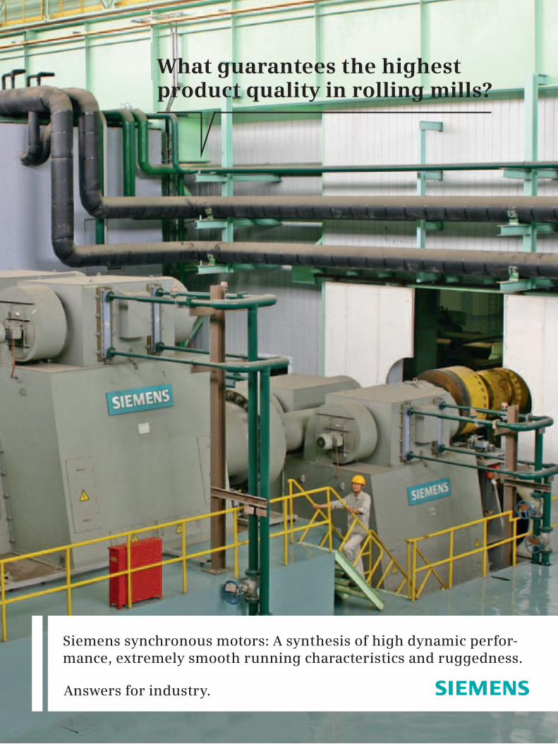
What guarantees the highest product quality in rolling mills?
Answers for industry.
Siemens synchronous motors: A synthesis of high dynamic perfor-mance, extremely smooth running characteristics and ruggedness.
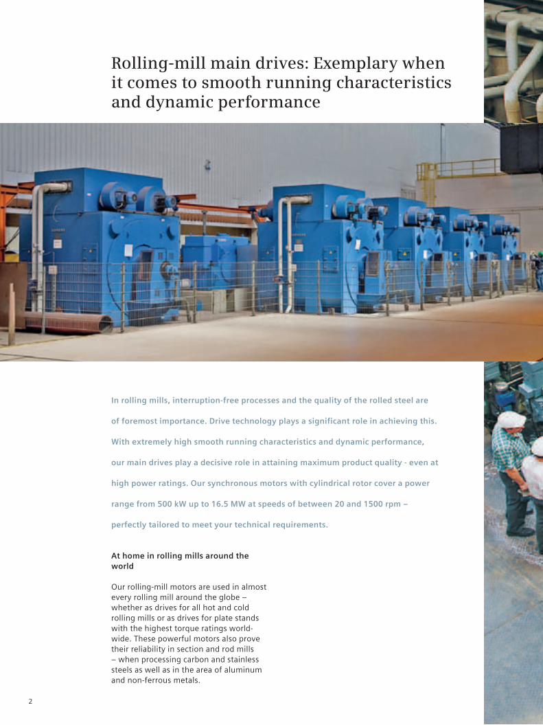
Rolling-mill main drives: Exemplary when it comes to smooth running characteristics and dynamic performance
In rolling mills, interruption-free processes and the quality of the rolled steel are
of foremost importance. Drive technology plays a significant role in achieving this.
With extremely high smooth running characteristics and dynamic performance,
our main drives play a decisive role in attaining maximum product quality - even at
high power ratings. Our synchronous motors with cylindrical rotor cover a power
range from 500 kW up to 16.5 MW at speeds of between 20 and 1500 rpm –
perfectly tailored to meet your technical requirements.
At home in rolling mills around the world
Our rolling-mill motors are used in almost every rolling mill around the globe – whether as drives for all hot and cold rolling mills or as drives for plate stands with the highest torque ratings world-wide. These powerful motors also prove their reliability in section and rod mills – when processing carbon and stainless steels as well as in the area of aluminum and non-ferrous metals.
2
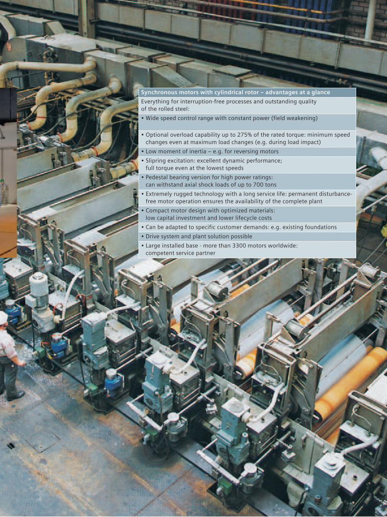
Synchronous motors with cylindrical rotor – advantages at a glanceEverything for interruption-free processes and outstanding quality of the rolled steel:•Wide speed control range with constant power (field weakening)
•Optional overload capability up to 275% of the rated torque: minimum speed changes even at maximum load changes (e.g. during load impact)
•Low moment of inertia – e.g. for reversing motors•Slipring excitation: excellent dynamic performance;
full torque even at the lowest speeds•Pedestal bearing version for high power ratings:
can withstand axial shock loads of up to 700 tons•Extremely rugged technology with a long service life: permanent disturbance-
free motor operation ensures the availability of the complete plant•Compact motor design with optimized materials:
low capital investment and lower lifecycle costs•Can be adapted to specific customer demands: e.g. existing foundations•Drive system and plant solution possible•Large installed base - more than 3300 motors worldwide:
competent service partner
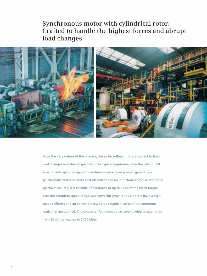
Synchronous motor with cylindrical rotor: Crafted to handle the highest forces and abrupt load changes
From the very nature of the process, drives for rolling mills are subject to high
load changes and shock-type loads. For typical requirements in the rolling mill
area - a wide speed range with continuous maximum power - generally a
synchronous motor is more cost-effective than an induction motor. Without any
special measures, it is capable of overloads of up to 275% of the rated torque
over the complete speed range. Our powerful synchronous motors have a high
speed stiffness and an extremely low torque ripple in spite of the enormous
loads that are applied. The converter fed motors also cover a wide torque range
from 30 all the way up to 2460 kNm.
4
Durable technology and compact motor design
When it comes to operating the complete plant, rolling-mill motors have an important role to play - or even a key one. The extremely rugged synchronous motor technology with a long service life plays a decisive role in the continuous disturbance-free operation of the motors – and in turn secures the availability of your complete plant. The compact motor design with opti-mized materials further ensures a low capital investment and lower lifecycle costs.
High availability and low maintenance costs
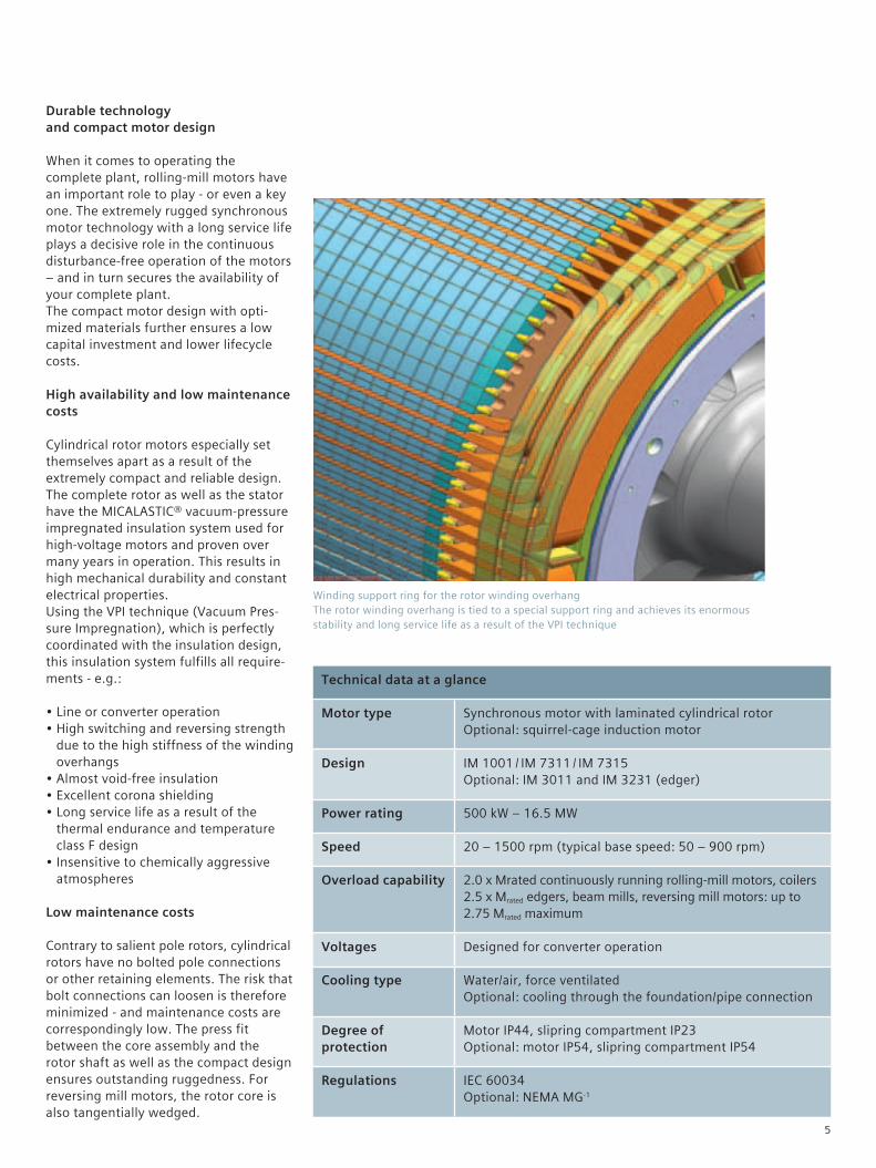
Cylindrical rotor motors especially set themselves apart as a result of the extremely compact and reliable design. The complete rotor as well as the stator have the MICALASTIC® vacuum-pressure impregnated insulation system used for high-voltage motors and proven over many years in operation. This results in high mechanical durability and constant electrical properties. Using the VPI technique (Vacuum Pres-sure Impregnation), which is perfectly coordinated with the insulation design, this insulation system fulfills all require-ments - e.g.:
•Line or converter operation•High switching and reversing strength
due to the high stiffness of the winding overhangs
•Almost void-free insulation•Excellent corona shielding•Long service life as a result of the
thermal endurance and temperature class F design
•Insensitive to chemically aggressive atmospheres
Low maintenance costs
Contrary to salient pole rotors, cylindrical rotors have no bolted pole connections or other retaining elements. The risk that bolt connections can loosen is therefore minimized - and maintenance costs are correspondingly low. The press fit between the core assembly and the rotor shaft as well as the compact design ensures outstanding ruggedness. For reversing mill motors, the rotor core is also tangentially wedged.
Winding support ring for the rotor winding overhang The rotor winding overhang is tied to a special support ring and achieves its enormous stability and long service life as a result of the VPI technique
Technical data at a glance
Motor type Synchronous motor with laminated cylindrical rotor Optional: squirrel-cage induction motor
Design IM 1001 / IM 7311 / IM 7315 Optional: IM 3011 and IM 3231 (edger)
Power rating 500 kW – 16.5 MW
Speed 20 – 1500 rpm (typical base speed: 50 – 900 rpm)
Overload capability 2.0 x Mrated continuously running rolling-mill motors, coilers 2.5 x Mrated edgers, beam mills, reversing mill motors: up to 2.75 Mrated maximum
Voltages Designed for converter operation
Cooling type Water/air, force ventilated Optional: cooling through the foundation/pipe connection
Degree of protection
Motor IP44, slipring compartment IP23 Optional: motor IP54, slipring compartment IP54
Regulations IEC 60034 Optional: NEMA MG-1
5
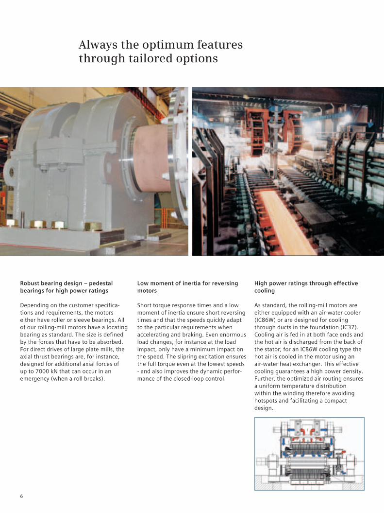
Robust bearing design – pedestal bearings for high power ratings
Depending on the customer specifica-tions and requirements, the motors either have roller or sleeve bearings. All of our rolling-mill motors have a locating bearing as standard. The size is defined by the forces that have to be absorbed. For direct drives of large plate mills, the axial thrust bearings are, for instance, designed for additional axial forces of up to 7000 kN that can occur in an emergency (when a roll breaks).
Low moment of inertia for reversing motors
Short torque response times and a low moment of inertia ensure short reversing times and that the speeds quickly adapt to the particular requirements when accelerating and braking. Even enormous load changes, for instance at the load impact, only have a minimum impact on the speed. The slipring excitation ensures the full torque even at the lowest speeds - and also improves the dynamic perfor-mance of the closed-loop control.
Always the optimum features through tailored options
High power ratings through effective cooling
As standard, the rolling-mill motors are either equipped with an air-water cooler (IC86W) or are designed for cooling through ducts in the foundation (IC37). Cooling air is fed in at both face ends and the hot air is discharged from the back of the stator; for an IC86W cooling type the hot air is cooled in the motor using an air-water heat exchanger. This effective cooling guarantees a high power density. Further, the optimized air routing ensures a uniform temperature distribution within the winding therefore avoiding hotspots and facilitating a compact design.
6
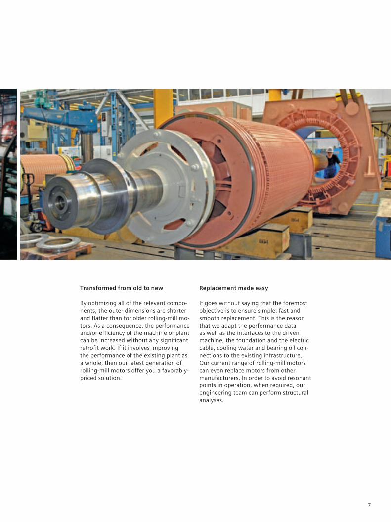
Transformed from old to new
By optimizing all of the relevant compo-nents, the outer dimensions are shorter and flatter than for older rolling-mill mo-tors. As a consequence, the performance and/or efficiency of the machine or plant can be increased without any significant retrofit work. If it involves improving the performance of the existing plant as a whole, then our latest generation of rolling-mill motors offer you a favorably-priced solution.
Replacement made easy
It goes without saying that the foremost objective is to ensure simple, fast and smooth replacement. This is the reason that we adapt the performance data as well as the interfaces to the driven machine, the foundation and the electric cable, cooling water and bearing oil con-nections to the existing infrastructure. Our current range of rolling-mill motors can even replace motors from other manufacturers. In order to avoid resonant points in operation, when required, our engineering team can perform structural analyses.
7
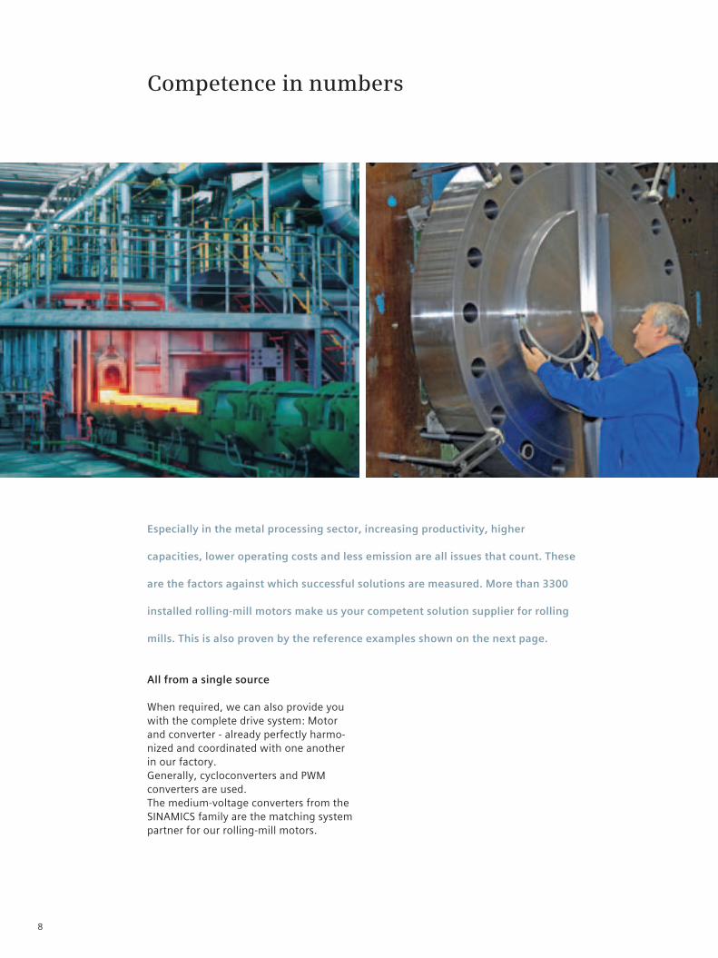
Competence in numbers
Especially in the metal processing sector, increasing productivity, higher
capacities, lower operating costs and less emission are all issues that count. These
are the factors against which successful solutions are measured. More than 3300
installed rolling-mill motors make us your competent solution supplier for rolling
mills. This is also proven by the reference examples shown on the next page.
All from a single source
When required, we can also provide you with the complete drive system: Motor and converter - already perfectly harmo-nized and coordinated with one another in our factory. Generally, cycloconverters and PWM converters are used. The medium-voltage converters from the SINAMICS family are the matching system partner for our rolling-mill motors.
8
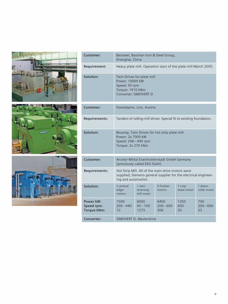
Customer: Baosteel, Baoshan Iron & Steel Group, Shanghai, China
Requirement: Heavy plate mill. Operation start of the plate mill March 2005.
Solution: Twin Drives for plate mill Power: 10000 kW Speed: 50 rpm Torque: 1910 kNm Converter: SIMOVERT D
Customer: Voestalpine, Linz, Austria
Requirements: Tandem of rolling-mill drives. Special fit to existing foundation.
Solution: Revamp, Twin Drives for hot strip plate mill Power: 2x 7000 kW Speed: 248 – 440 rpm Torque: 2x 270 kNm
Customer: Arcelor-Mittal Eisenhüttenstadt GmbH Germany (previously called EKO Stahl)
Requirements: Hot Strip Mill. All of the main drive motors were supplied, Siemens general supplier for the electrical engineer-ing and automation.
Solution: 2 vertical edger motors
1 twin reversing mill motor
5 finisher motors
1 crop shear motor
1 down- coiler motor
Power kW: Speed rpm: Torque kNm:
1500 200 – 440 72
6000 45 – 100 1273
6400 200 – 600 306
1250 600 20
700 200 – 600 33
Converter: SIMOVERT D, Masterdrive
9
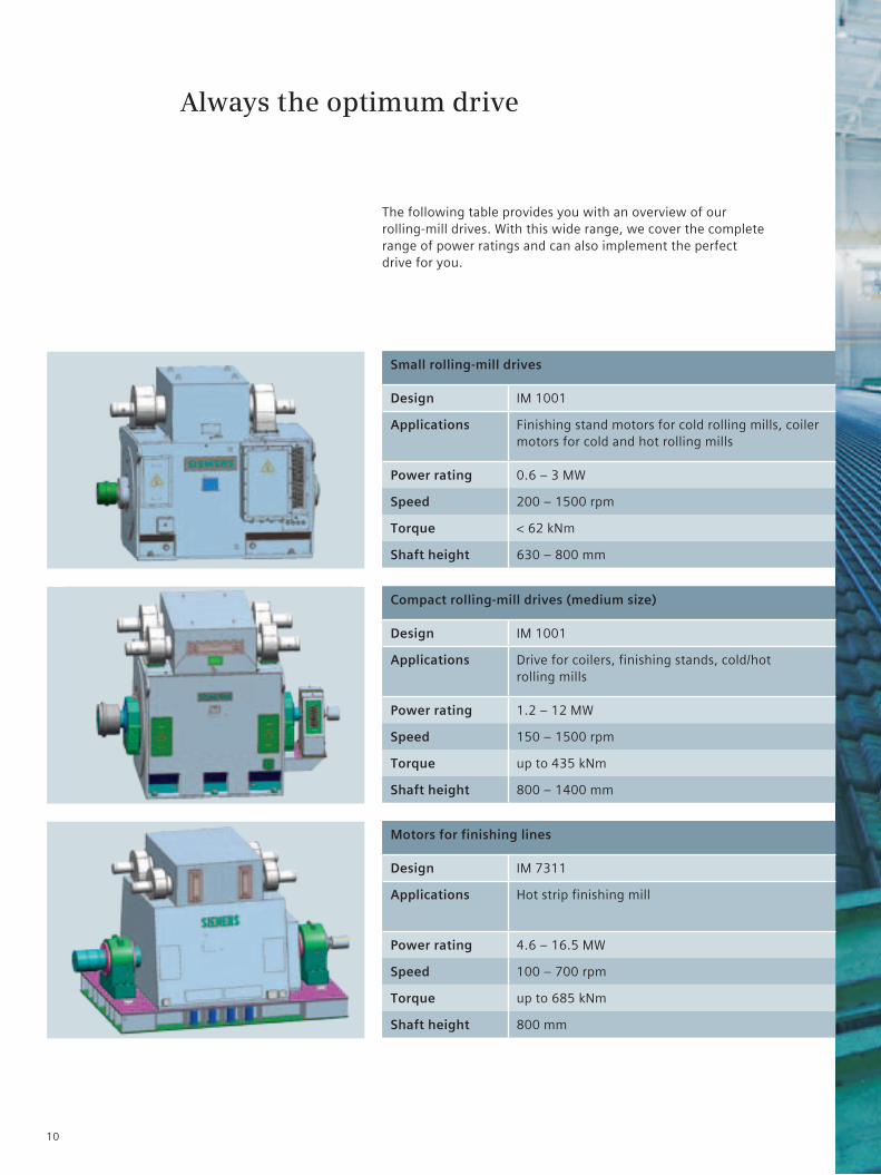
Small rolling-mill drives
Design IM 1001
Applications Finishing stand motors for cold rolling mills, coiler motors for cold and hot rolling mills
Power rating 0.6 – 3 MW
Speed 200 – 1500 rpm
Torque < 62 kNm
Shaft height 630 – 800 mm
Compact rolling-mill drives (medium size)
Design IM 1001
Applications Drive for coilers, finishing stands, cold/hot rolling mills
Power rating 1.2 – 12 MW
Speed 150 – 1500 rpm
Torque up to 435 kNm
Shaft height 800 – 1400 mm
Motors for finishing lines
Design IM 7311
Applications Hot strip finishing mill
Power rating 4.6 – 16.5 MW
Speed 100 – 700 rpm
Torque up to 685 kNm
Shaft height 800 mm
Always the optimum drive
The following table provides you with an overview of our rolling-mill drives. With this wide range, we cover the complete range of power ratings and can also implement the perfect drive for you.
10
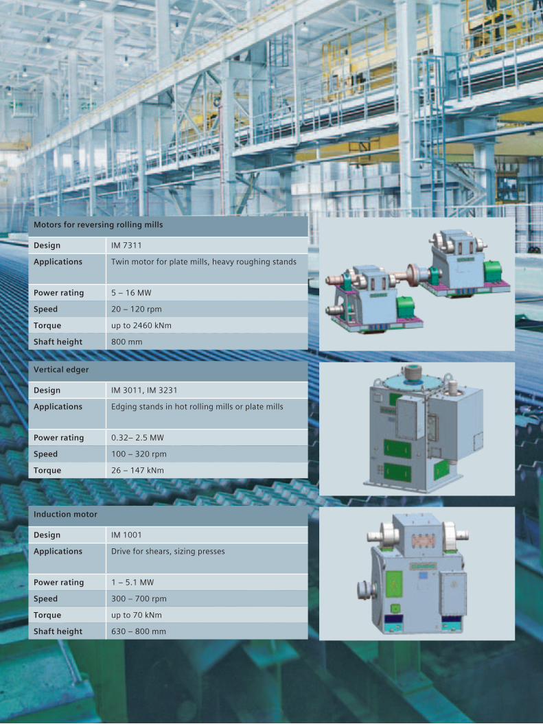
Motors for reversing rolling mills
Design IM 7311
Applications Twin motor for plate mills, heavy roughing stands
Power rating 5 – 16 MW
Speed 20 – 120 rpm
Torque up to 2460 kNm
Shaft height 800 mm
Vertical edger
Design IM 3011, IM 3231
Applications Edging stands in hot rolling mills or plate mills
Power rating 0.32– 2.5 MW
Speed 100 – 320 rpm
Torque 26 – 147 kNm
Induction motor
Design IM 1001
Applications Drive for shears, sizing presses
Power rating 1 – 5.1 MW
Speed 300 – 700 rpm
Torque up to 70 kNm
Shaft height 630 – 800 mm
Siemens AG Industry Sector Large Drives Nonnendammallee 72 13629 BERLIN GERMANY
Subject to change without prior notice Order No.: E20001-A430-P500-X-7600 Dispostelle 21503 WÜ/30843 GD.LD.XX.LD.SO.52.1.01 WS 12102.0 Printed in Germany © Siemens AG 2010
The information in this brochure only provides a general descrip-tion and performance features. For a specific application, this information will not always be applicable in the form described here. This information can also change due to ongoing product development. The required performance features are only bind-ing if they have been expressly agreed upon in the form of a written contract. All product designations could be trademarks or product names of Siemens AG or other companies, which, if used by third par-ties, could infringe the rights of their owners.www.siemens.com/large-drives
More information:
Siemens AG Industry Sector Industry Solutions Metals Technology Schuhstraße 60 91052 Erlangen, Germany E-mail: [email protected]
www.siemens.com/large-drives
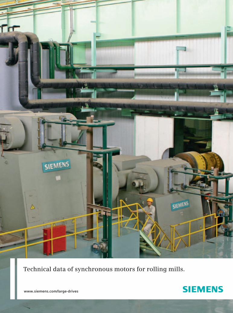
Technical data of synchronous motors for rolling mills.
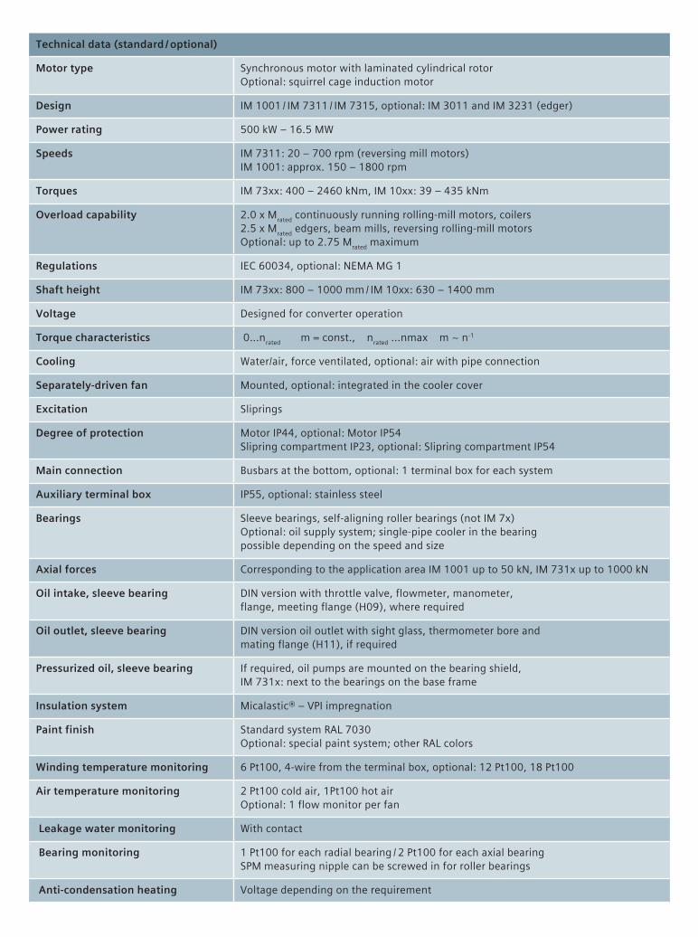
Technical data (standard / optional)
Motor type Synchronous motor with laminated cylindrical rotor Optional: squirrel cage induction motor
Design IM 1001 / IM 7311 / IM 7315, optional: IM 3011 and IM 3231 (edger)
Power rating 500 kW – 16.5 MW
Speeds IM 7311: 20 – 700 rpm (reversing mill motors) IM 1001: approx. 150 – 1800 rpm
Torques IM 73xx: 400 – 2460 kNm, IM 10xx: 39 – 435 kNm
Overload capability 2.0 x Mrated continuously running rolling-mill motors, coilers2.5 x Mrated edgers, beam mills, reversing rolling-mill motorsOptional: up to 2.75 Mrated maximum
Regulations IEC 60034, optional: NEMA MG 1
Shaft height IM 73xx: 800 – 1000 mm / IM 10xx: 630 – 1400 mm
Voltage Designed for converter operation
Torque characteristics 0…nrated m = const., nrated …nmax m ∼ n-1
Cooling Water/air, force ventilated, optional: air with pipe connection
Separately-driven fan Mounted, optional: integrated in the cooler cover
Excitation Sliprings
Degree of protection Motor IP44, optional: Motor IP54 Slipring compartment IP23, optional: Slipring compartment IP54
Main connection Busbars at the bottom, optional: 1 terminal box for each system
Auxiliary terminal box IP55, optional: stainless steel
Bearings Sleeve bearings, self-aligning roller bearings (not IM 7x) Optional: oil supply system; single-pipe cooler in the bearing possible depending on the speed and size
Axial forces Corresponding to the application area IM 1001 up to 50 kN, IM 731x up to 1000 kN
Oil intake, sleeve bearing DIN version with throttle valve, flowmeter, manometer, flange, meeting flange (H09), where required
Oil outlet, sleeve bearing DIN version oil outlet with sight glass, thermometer bore and mating flange (H11), if required
Pressurized oil, sleeve bearing If required, oil pumps are mounted on the bearing shield, IM 731x: next to the bearings on the base frame
Insulation system Micalastic® – VPI impregnation
Paint finish Standard system RAL 7030 Optional: special paint system; other RAL colors
Winding temperature monitoring 6 Pt100, 4-wire from the terminal box, optional: 12 Pt100, 18 Pt100
Air temperature monitoring 2 Pt100 cold air, 1Pt100 hot air Optional: 1 flow monitor per fan
Leakage water monitoring With contact
Bearing monitoring 1 Pt100 for each radial bearing / 2 Pt100 for each axial bearing SPM measuring nipple can be screwed in for roller bearings
Anti-condensation heating Voltage depending on the requirement
Recommended