Welding Research Sponsored by the Welding Research Council
SUPPLEMENT TO THE WELDING JOURNAL, DECEMBER 1972
Procedures for Evaluation of Fracture Toughness of Heat-Affected Zones
BY L. J . McGEADY
A good quality weld requires adequate fracture toughness of base metal, weld metal, and heat-affected zone (HAZ). Reliable methods are available for the first two but the HAZ evaluation has posed particular experimental problems which are dealt with in this paper.
In t roduct ion
Welded structures must be viewed essentially as three-component composites of weld metal, plate and heat-affected zone (HAZ). Inadequate toughness in any one is a threat to structural integrity.
In carbon steel weldments the fracture situation is generally a plate problem in the main. The protective geometric aspects of U- or Vee-groove geometries and the toughness levels in welds deposited wi th modest control generally el iminate the HAZ and weld metal as common paths of major failure. However f laws in either area are capable of extension to the plate. Therefore the key to catastrophic fracture control has centered on the use of steel of sufficient-
L. J. McGeady is professor and head of the Department of Metallurgical Engineering at Lafayette College, Easton, Pa.
ly low transit ion temperature. The World War II ship failure problem is an excellent case for reference.
In weldments of quenched and tempered steels, the potential for extended fractures not only in plate but also in either HAZ or weld metal must be considered. The steels in this group, because of differences in alloy content and kind differ widely in plate toughness characteristics and in sensitivity to HAZ damage in welding. At the same t ime the higher strength requirements for weld metals for these steels pose considerations in respect to toughness wh ich become more acute as advanced strengths or more economic compositions or both are sought.
The control of fracture via the plate transit ion temperature wh i le possible for carbon steel weldments is insuff icient for quenched and tempered steel weldments. Evaluative methods for the quenched and tempered (Q+T) steel must take into account the sus
ceptibility of all weldment components to fracture. Two approaches are possible. Testing weldments in composite specimen procedures such as the Explosion Bulge or Delta allows identification of the most fracture prone elements. Procedures to test the toughness of the weld, plate and HAZ represent a second approach.
The Drop-Weight (DW) and Dynamic Tear (DT) tests have been used widely to characterize plate and weld metal toughness separately and quantitatively. From tests using these two specimens, data are presented in this report to demonstrate the applicability of these two procedures to the HAZ as wel l . Results of composite specimen tests and single component tests wi l l be shown to be in agreement when applied to several steels. Consequently the understanding of results of composite specimens tests is enhanced and their applicability better defined. At the same t ime the
W E L D I N G R E S E A R C H S U P P L E M E N T ! 569-s
successful characterization of HAZ toughness by the DW and DT procedures provides quantitative reference data for use in the Fracture Analysis and Ratio Analysis Diagrams.
T h e Weldab i l i ty Prob lem in Relat ion to Fracture Toughness in C a r b o n Stee ls
The ship failures in Wor ld War II typified the weldabil i ty problem in carbon steel structures. The intensive investigation of these failures revealed that the fracture problem was essentially a plate metal problem, that is, high plate transit ion temperatures, since they were the path for extended failures. Adequate toughness in the weld metal was possible through use of commercial fi l ler materials deposited under modest control. Sufficient compensation for metallurgical damage via the protective geometric aspects of joints w i th U-or Vee-groove configurations was effective in minimizing extended fractures in the HAZ.
However f laws in either the weld metal or heat-affected zone could and did act as sources for fractures which were transmitted to and extended in the plate. As a consequence a two-pronged attack was brought to bear on the carbon steel fracture problem — one, to produce plate w i th lower transit ion temperatures, the other to identify and el iminate creation of f laws in welding.
In the effort, a host of tests was developed. In the context of the problem, all were called weldabil i ty tests. Some were designed to measure plate toughness more satisfactorily or completely than possible by the Charpy test; these were regarded as service tests. Others gene ra l l y termed fabrication tests were designed to measure susceptibility of the base plate to heat-affected zone cracking. One was the bead on plate cracking test in wh ich a weld bead was deposited on the plate material and then examined for evidence of cracking in the HAZ under the natural shrinkage stresses generated by weld cooling.
A second procedure was the "c l ip test " in which a piece of plate or " c l i p " was welded w i th a single f i l let weld to form a Tee-joint w i th the material being examined. Testing consisted of striking the clip, which was the vertical bar of the Tee-joint, w i th a sledge to determine whether in breaking it away, fracture took place in the brittle coarse-grained HAZ of the subject material.
Another approach to determine susceptibility of either weld metal or HAZ to cracking in fabrication was the Lehigh Restraint1 Specimen. In
this test, a weld deposited in a double-U-joint was restrained from shrinking in cooling. Variable restraint al lowed definit ion of a threshold value above which cooling cracks would form. Either weld metal or HAZ could fail depending on the materials and welding conditions.
Consideration of the HAZ as an area of potential difficulty led to various researches. Doan, Stout, Tor and Frye2 proposed a systematic approach to controll ing hardness and britt leness in the coarse-grain heat-affected zone through understanding the relations between weld heat input, plate thickness and temperature, and corresponding cooling rates in the weld area and Jominy test data. Other i nves t i ga t i ons showed potential embri t t lement in regions of the HAZ susceptible to strain-aging type phenomena. Stil l others showed embrit t lement possible in the metallurgical areas heated just above the lower critical temperature.
However, the situation w i th the carbon steel plates remained the same, namely the potential for long disastrous failures in plate w i th the weld zone l imited to the role of site or source of init iat ion. Commercial welding material and control of welding conditions could be relied on to el iminate the weld zones as paths for major fracture. Ult imately it became clear that the overall approach to fracture safe design w i th these steels required the use of sufficiently low t ransition temperature plate material to prevent extensive fracture.
Weldabi l i ty and Fracture Toughness of H i g h - S t r e n g t h Stee ls
Weldabil i ty is a more complex practical matter for the high-strength steels than for the carbon steels. Not only the plate but also the heat-affected zone and the weld metal require consideration. Each can be viewed as a separate concern.
Conceptually and for practical testing purposes the weld metal is isola-ble for separate handling. However the fracture toughness problems there must be considered in relation to the steels being welded. For carbon steels the problem is minimal. Adequate toughness or toughness equivalent to that of the plate is readily obtained in the weld metal w i th relatively modest attention to the welding process using readily available fi l ler materials. Welding of high-strength steels presents more str ingent demands. As in the plate materials to wh ich they are applied the problem is to maintain adequate toughness at elevated strength levels. Thus the weld metal toughness problem becomes more acute as higher
strengths or more economic compositions or both are sought. Optimum properties are realized only by careful selection of fil ler material and appropriate control of the welding process.
Like the weld metal, plate material can be handled as a distinctly separate weldment component. It is clearly recognized that differences in amount and kind of a l loyirg elements lead to differences in toughness characteristics at any strength level. Some of the steels in the Q+T group show neither a sharp transit ion temperature nor a high energy shelf whi le others do. It is evident that in Q+T steel weldments the plate remains a critical element for fracture control.
Whi le the plate metal and HAZ can be viewed as separate entit ies, the plate must be regarded as the parent of the HAZ. Both are subject to the same metallurgical considerations. The fracture toughness realizable in each is dependent upon the nature and level of alloy content. The plate is heat treated for opt imum toughness in prescribed thermal cycling processes under control in the mil l . The more complex cycling experienced in the heat-affected zone is subject to less control in welding. It is unrealistic to expect the heat-affected zone to exhibit the same microstructures found in the plate. Control of the welding process must be the route to produce HAZ microstructures w i th opt imum properties in a given steel. In general the hardenability of the steel dictates the latitude of welding conditions allowable for retention of the most favorable HAZ microstructure w i th resultant minimal damage.
Weldabi l i ty Tests
Among the various procedures proposed for evaluating fracture performance of weldments three fundamentally different approaches can be recognized. One is to measure the tendency of plate to accept weld in i tiated fractures restricted to the trans-verse-to-weld path of travel. A second is to characterize the toughness of weld, plate and HAZ separately. A third is to use composite test procedures which allow simultaneous loading of all three components and a self-selected fracture path in the component of least resistance.
In specimens such as the Kinzel or Lehigh Longitudinal Bend tests3
which force fracture transverse to the weld, the specimen is prepared by deposit of a weld bead on a plate surface along the length of the specimen. A notch cut across the width of the plate leaves a small amount of weld area at the root as a source of fracture in bend testing. Fracture so initiated is forced to take an extended
570-s I D E C E M B E R 1 9 7 2
path across the plate. Thus the fracture through the weld zone represents a minor fraction of the total fracture surface. Nevertheless, this test is sensitive to welding conditions and materials when used on plate capable of considerable ductil ity and represents an excellent simple approach to weldabil i ty test ing. When transition curves are determined w i th this procedure, the effect of increasing weld zone britt leness is reflected in higher transit ion temperatures. When tested wi th extremely britt le weld zones the specimen becomes a slow-bend nil-ductil ity t r a n s i t i o n (NDT) temperature test of the plate, that is, a test of the parent material in response to a dynamic crack.
The Charpy test has long been used as a procedure to characterize fracture toughness of individual weldment components separately. From the early days of ship failure investigations when it was used wi th eminent success on carbon steel plates, this procedure has seen widespread acceptance and incorporation into codes for welding in application to weld metals, plate materials and heat-affected zones. The vast amount of data accumulated w i th this test procedure is an inducement to continued use. Often, like a hardness test it is used for quality control. However the test presents some diff iculty when considered for quantitative toughness measurement. It has been amply demonstrated that correlations of Charpy data w i th data from other toughness tests are difficult and that, say 15 ft- lb Charpy V-notch energy in one steel may mean something entirely different in another. Thus complications occur in attempts at comparisons across broad famil ies of steels.
The test presents other difficulties as in testing of thick sections or thick welds where tests at surface, center and intermediate positions may be mandatory, consequently expensive and in the case of nonuniform material, productive of perplexing data. Nevertheless the specimen has been applied to measurements of heat-affected zone toughness by posit ioning the base of the notch in various locations in the heat-affected zone. The method is tedious and fracture cannot be relied on to fol low a fixed desired path through the complex, non-uniform, curved plane geometry of the heat affected zone. As a result data are susceptible to considerable scatter and difficulty of interpretation.
Before proceeding to a brief analysis of composite specimen tests it should be recognized that the heat-affected zone presents particular problems in toughness characterizat ion. Unlike the weld metal or plate metal it is not physically isolable for
Table 1
Steel Code
J20 J25 J26 J31 J32 J34 J38 L6
L15
A543 A537B
— Chemical Compositions
C
0.15 0.12 0.22 0.18 0.18 0.18 0.18 0.21
0.19
0.14 0.18
Mn
0.81 0.32 0.88 0.87 1.15 0.58 0.84 0.57
0.67
0.30 1.21
Si
0.25 0.17 065 026 0 28 028 0 64 0 28
0.26
0.25
Co
P
0.013 0.006 0.023 0.011 0.009 0.015 0.006 0.008
0.009
0.010 0.010
of Stee s Studied
mposition, wt-
S
0.021 0.014 0.022 0.019 0.024 0.019 0.019 0.024
0.026
0.018 0.025
Ni
0.83 2.33 0.13 0.25 0.07 0.20 0.05 0.03
1.36
2.94 0.16
Vo
Cr
0.52 1.26 0.94 0.66 0.05 1.05 0.69
1.62 0.10
Mo
— 0.34 0.48 0.24 0.25 0.25 0.19 0.69
0.64
0.46 0.03
V
0.24 — —
0.04 0.01 0.03 0.03
Other
0.55 Cu —
0.10 Cu 0.10AI 0.06 Al 0.10 Al 0.10 Al 0.004B, 0.06AI 0.003B, 0.07AI
0.30Cu, 0.04AI
direct testing. It must be tested in situ as a center element sandwiched between weld metal and parent plate. In usual commercial joints it is present as an undulated curved plane slanted to the plate surface and thus protected to a degree from fracture in both through-the-plate and across-the-plate directions. Addit ionally it is a relatively narrow zone. For these reasons containment of fracture wi th in it for purposes of fracture toughness measurement poses considerable experimental difficulty as the lack of available data clearly indicates.
However, as fol lowing sections wi l l show, both the Drop-Weight (DW) and Dynamic Tear (DT) test procedures are adaptable to quantitative toughness characterization of the HAZ. Prior to such adaptations the principal definitive approaches to determining the proclivity of the HAZ to fracture were the composite specimen tests such as the Explosion Bulge, Drop Weight Bulge and more recently the Delta test.
S o m e C o m p o s i t e W e l d m e n t Tests
A. The Explosion and Drop Weight Bulge Tests
The Explosion Bulge test (EB) was one of the earliest used to'direct at-
DROP WEIGHT
BULGE TEST
15" CIRCULAR fc OPENING IN SUPPORT v Y ^ - -DJE TO ALLOW BULGE TO DEVELOP
jFALLING WEIGHT STRIKES TUP
I . OF SOFT ALUMINUM
a ,Jf> :
% ^ - FULL THICKNESS PLATE
SUPPORT DIE ON CONCRETE PAD
Fig. 1 — The Drop Weight Bulge test. A 2-in. diam surface patch of Hardex-N at the center of the "down" side serves as a crack initiator
tention to heat-affected zone fracture problems. In conducting the test a specimen 1 4 x 1 4 in. is positioned over a circular opening in a die and loaded by offset explosion. Beginning in a small britt le weld bead a crack of natural sharpness propagates from the specimen center toward the specimen edges. Tests over a range of temperatures allow determination of NDT, fracture transit ion elastic (FTE) and fracture transit ion plastic (FTP) temperatures which are critical in the systematic presentation of the Fracture Analysis Diagram (FAD). In addit ion to the importance of the explosion bulge test to fracture analysis and engineering fracture mechanics, the specimen is interesting in that fracture is not biased in travel direction since a 1 to 1 loading situation prevails. Hence it is appropriate as a searching tool to determine the line of least fracture resistance in welded specimens.
A modified version of the Explosion Bulge test shown in Fig. 1 is the Drop Weight Bulge (DWB) test. Like the EB specimen, the DWB specimen is positioned over a circular opening in a die and loaded by the simple procedure of dropping sufficient weight on the specimen from a shop crane or other device.
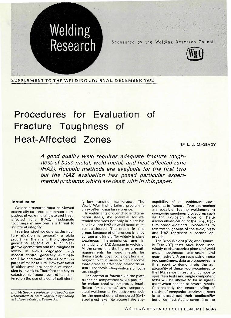
In a program of tests,4 seven steels, obtained through regular commercial channels, were tested as fully butt welded specimens in the drop-weight bulge procedure. Al l welds were made w i th E11018M electrode w i th 80 k j / i n . maximum heat input and maximum interpass temperature of 125 F. Specimens at 30 F were subjected to repeated impacts from a 6-ton weight fal l ing f rom a height of 8 ft until eye-visible fracture occurred. Compositions of the steels are given in Table 1. Mechanical properties are given in Table 2. Some results are shown in Table 3. A significant point is the tendency for HAZ failures to be long. Figure 2 illustrates the range of DWB performance found, ranging
W E L D I N G R E S E A R C H S U P P L E M E N T ! 571-s

'Hfl
-*m J-20
Fig. 2 — Fractured DWB specimens. Steel J20 fractured in a HAZ path 20 in. long in one 8-ft impact of the 6-ton weight. Four impacts produced a fracture confined to the weld metal in Steel J25. Both tests at 30 F, both 1-in. plates
J-2
Table 2
Steel code
J 2 0
J25
J26
J31
J32
J 3 4
J38
L6
L15
A543
A537B
(a) Values
— Tensile
Fracture code
Plb) Tic) P T P T P T P T P T P T P T P T P T P T
given are th<
Test Results
Plate thickness
in.
7 / 8 7 / 8
1-1 /8 1-1/8
1 1 1
1
1
1
high and low values (b) Fracture parallel io roi i (c) Fracture transverse to rollina directions.
0.2% YS ksi
124.0 123.4
83.3 82.9
106.8 105.0 113.6 112.6 116.3 116.3 111.3 111.2 108.8 111.3 100.0
100.0
88.0
62.6
UTS ksi
129.0 128.9
97.7 97.8
120.1 108.9 121.4 121.1 121.3 122.1 117.3 118.0 117.7 111.5
Red. of area, %
53.1 62.0 68.0 75.1 53.5 58.7 48.9 59.7 53.3 61.1 53.2 65.4 59.2 66.4
Not tested
Not tested
110.0
83.8
measured at 30 F.
—
Elong.,
% 16.0 18.8 24.0 27.0 19.0 21.0 15.0 17.5 16.3 18.0 16.5 18.8 19.0 19.5 —
~ 25
27
Charpy-V, f t- lb
at 30 FO)
32-29 51-48
105-99 165-162
32-29 47-46 26-25 48 -44 38-30 44 -42 28-27 51 -47 31 -30 56-52 28 40 20 54 76
145 60 82
Table Bulge
Code
J20 J25
J26 J31 J32 J 3 4
J38
3 — Drop Test Resi
No. of impacts
to fai lure
1 3
3 3 3 2
4
-Weight Its at 30 F (a)
Length of
crack, . (b)
in. Location
20 HAZ 4 Weld (minor pla
tear) 6 Plate
18 Plate 15 HAZ
7 Plate (3 in.) and weld (4 in.)
20 HAZ
(a) Long fractures occured in HAZ and plate only at this temper (b) om*,
DELTA
TEST
ture. steelJ25 resisted plate and HAZ fracture or both
" (7 LOAD TRANSMITTED SLOWLY AT
' CENTEP OP SPECIMEN IN COMPRESSION LOADING
i * ^ = # ' FULL THICKNESS 60" DOUBLE ~7 BEVEL WELDS. GROUND FLUSH
-• FULL THICKNESS PLATE 24" x 2 4 " * 2 4 "
-SUPPORT AT THREE CORNERS AT 2 2 " DISTANCES
f rom the worst case, a flat break performance in J 2 0 specimens after one impact which produced a full 20- in. fracture in the HAZ to the best case, a 4- in. weld metal fracture in J25 steel after 3 impacts resulting in a 4- in. bulge at specimen center.
In a later series of identical tests, steel L6 in welded condit ion was tested over temperature ranges using the 6-ton weight and a repeated 4-ft drop procedure until onset of failure. Table 4 gives the test results. NDT for this steel was - 5 0 F, and of the weld and HAZ each - 4 0 F.
These tests showed several items of note, namely the dependence of
fracture location on test temperature, in keeping wi th NDT concepts, and tendency to fractures in the HAZ at test temperatures above NDT of plate, weld and HAZ.
In summary the DWB is a simply conducted discriminating test of weldability. Data from this dynamic type test correlate wel l w i th those from the slowly loaded Delta test specimen to be considered. B.The Delta Test
This test illustrated in Fig. 3 like the DWB is a prototype test representing part of a weldment. The specimen is tested in a slow loading wh ich causes fracture to begin in the brittle crack
Fig. 3 — The Delta test procedure as conducted on welded plate. A 2-in. diam surface patch of Hardex-N at the center of the "down" side serves as a crack initiator. Both 1 -in. plates
starter patch at the center of the " d o w n " or tension face of the specimen. The specimen can be either of unwelded plate containing the crack starter patch weld or of plate welded in any desired manner.
Failure is defined as the appearance of a fracture, extended from the crack starter, wh ich ordinarily occurs at a maximum load. Fracture in welded specimens is free to fol low
572-s I D E C E M B E R 1 9 7 2

3.1
3,0
2,5
2,3
1,5
1,0
-160
DELTA TESTS A537-B STEEL
<
0
/
3
• 1 1* p
•
r • NDT
O
PLATE
O
•
0
A
o
•
i •
= NON-WELDED BRITTLE PATCH ONLY
•= AS-WELDED 5 PASSES PER SIDE
= PREHEATED 100°F
= STRESS-RELIEVED
3 noo°r » AS-WELDED
55,000 J/IN, MAX.
ALL WELDS WITH E301GC1
= SUE-ARC WELDED
ALL FAILURES ARE IH THE PLATE.
-120 -80 -10
TEST TGttRATURE, 0E
Fig. 4 — Results of Delta tests of 1-in. A537 steel in prime plate and welded conditions. All fractures in welded specimens occurred in plate
3,1
;.:
2.5
2.3
1.0
~ / WIN
DELTA TESTS A513 CLASS 1
N0N WELDED SPECIMENS, BRITTLE PATCH ONLY
AS-WELDED 55,000 J / I
OB
NDT "ALL WELD METAL
FAILURES
O = AS-WELDED STA'IDAPD PREHEATED TO°F
STRESS-RELIEVED 9 1100°F
ALL WELDS WITH E11018I1, 80 KJPI
SIB-ARC WELDED
J
-160 -120 -80 -10 0
TEST TEMPERATURE, °F
Fig. 5 — Results of Delta tests of 1 -in. A543 steel in prime plate and welded condition. All fractures in welded specimens occurred in the weld metal
the path of least fracture resistance, weld metal, HAZ or plate. Tests conducted over temperature ranges develop transition curves. The most immediately useful index of failure is the center point deflection at failure but other measurements including yield, maximum and fracture loads, energy to cause failure, length of init ial fracture, ease of extending failure, and path of failure are possible. The specimen is sensitive to base plate composit ion, weld fil ler metal, welding procedure and test temperature.
Temperature dependency of fracture path in welded specimens is an essential possible result because as in the DWB or EB test, fracture is free to occur in the least resistant path. Thus, essentially three basic patterns of performance are possible depending on the temperature vs. fracture toughness characteristics of the three individual weld zones. That is, either weld metal, plate or HAZ can control the fracture process.
Given the deflection at failure vs temperature characteristics of base plate (unwelded except for the crack starting brittle patch), it fo l lows that welded specimens of that material cannot show better performance. They can show equal performance only if the weld metal and HAZ show equivalent or superior fracture resistance. This is illustrated in Fig. 4,5-6
Similarly, if the weld deposit has less fracture resistance than the plate, the weld metal wi l l control the fracture
characteristics when the HAZ retains sufficient fracture resistance. This is illustrated by the tests described by Fig. 5. Finally, sufficient deteriorat ion in the HAZ wi l l make it an available path for fracture and result in Delta specimen performance of the type shown in Fig. 6. Properties of the steels are given in Tables 1 and 2.
2,5
2,0
J 1.
1,0
PRIME PLATE
Many instances of performance patterns intermediate between those shown in Figs. 4, 5, and 6 are possible and have been found but the pr inciples illustrated appear inviolable. The transition temperature for unwelded parent plate in the Delta test determined from the deflection at fai l ure vs test temp, curve has shown ex-
DELTA T^STS
CODE L6 STEEL
WELDED 50,000 KJPI S E12G18M
*W+HAZ
HAZ HAZ
WELDED 85 KJPI E11018M
NDT LATE
"5i_ -120 -80 -40 o m
TEST TEMPERATURE, ° r
80 120
Fig. 6 — Results of Delta tests of 1 -in. L6 steel, prime plate and welded. Lower heat input welding considerably reduced tendency to HAZ fractures
W E L D I N G R E S E A R C H S U P P L E M E N T ! 573-s
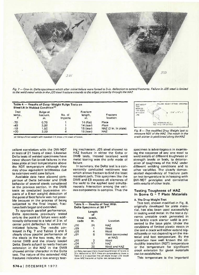
'
m - • JZO
Fig. 7 — One-in. Delta specimens which after initial failure were forced to 3-in. deflection to extend fractures. Failure in J25 steel is limited to the weld metal while in the J20 steel fracture extends to the edges primarily through the HAZ
Table 4 -Steel L6
Test temp.,
F
-70 -40 -10 +70
- Results of Drop- W e in Welded Condition131
Bulge at fracture,
in.
0.75 2,00 1.50 2.00
gh t Bulge Tests
No. of impacts
1 1 2 4
on
Fracture length,
in.
1 4 (flat) 14 (tear) 15 (tear) 1 5 (tear)
Fracture location
Plate Plate HAZ (2 in. in plate) HAZ
OROP WEIGHT TEST
MODIFIED FOR TESTS
OF FUSION
LINE
jFALLING WEIGHT STRIKES SPECIMEN
-•••'7*-""' \
• ^*" } - 3 '/z" x 14" x I "
FULL THICKNESS WELD SEE FIG 2 FOR DETA LS
(a) Using a 6-ton weight with repeated 4-ft drops until onset of failure.
Fig. 8 — The modified Drop Weight test to measure NDT of the HAZ. The notch in the crack starter is positioned along the HAZ
cellent correlation wi th the DW-NDT in tests of 21 heats of steel. Likewise Delta tests of welded specimens have never shown flat-break failures in the base plate at test temperatures above the NDT temperature although they may show equivalent britt leness due to extensive weld zone failure.
Available data have al lowed comparison of Delta behavior and DWB behavior of several steels considered in the previous section. In the DWB tests as conducted (successive impacts of a 6-ton weight) detection of the point of f irst failure was not possible because in the process of being subjected to the final impact, fractures both began and extended.
To approach parallel performance, Delta specimens previously tested only to the point of failure were addit ionally deformed to a total of 3 in. of center point deflection to extend the initiated failures. The results portrayed in Fig. 7 and Tables 3 and 5 clearly show parallel performance of the steels in the two tests, the dynamic DWB and the slowly loaded Delta. Steels subject to ready fracture extension in the HAZ in the DWB showed similar character in the Delta test. The nature of the extended HAZ fractures indicates a low-energy tear
ing mechanism. J25 steel showed no HAZ fracture in either the Delta or DWB tests. Instead localized weid metal tearing was the only mode of failure.
In summary, the Delta test is a conveniently conducted weldment test which allows fracture to f ind the least resistant path. This specimen like the DWB and EB exposes all elements of the weld to the applied load simultaneously. Interaction among the various components is complex. Thus the
Table 5 -- Results of Test With Delta Specimen at 3 0 F ( a |
Steel code
J20 J25 J26 J31
J32 J34 J38
Length of
crack. in.
24 1 4 8
2 17 20
Location
HAZ Weld Weld Weld (terminated
at HAZ) Weld HAZ Weld and HAZ
(a) Delta test specimens tested beyond onset of failure to 3 in. deflection at 30 F Data are comparable to those in Table 3. It is expected that all steels except J25 would show HAZ fractures at higher test temperatures.
specimen is advantageous in examining the response of any one steel to weld metals of different toughness or strength levels or both, to deterioration of toughness of the HAZ under different welding conditions and to other variables. The clearly demonstrated dependency of fracture path on test temperature is in keeping w i th DW-NDT principles and correlative w i th results of other tests.
Test ing Toughness of H A Z in S o m e Q + T Plate Mater ia ls
A. The Drop Weight Test This test, shown modified in Fig. 8,
originally developed for plate material, has also been used successfully in testing weld metal. In the test a dynamic unstable crack generated in the brittle crack starter weld is presented to the base plate. Under the conditions of limited plastic strain in the test a crack wi l l either extend significantly or not depending on the material and test temperature. By the procedure now wel l known the ni l -ductility transit ion (NDT) temperature or the temperature for signif icant crack extension for given materials can be established.
This temperature is the important
574-s I D E C E M B E R 1 9 7 ?

reference for the Fracture Analysis Diagram (FAD) and has been shown to have a high correlation index w i th other signif icant fracture tests and service failures. The test has been applied to weld metal as wel l as to plate materials ranging from 30 to 100 ksi yield strength. A simple step can be taken to measure the NDT temperature for weld metal by preparing a specimen so that fracture traverses through the weld metal of a fully welded joint.
In a recent NRL investigation4 it was found possible to measure the NDT temperature of heat affected zones in various steels. This was accomplished by preparing DW specimens of standard dimensions having transverse butt welds at the specimen center. A relatively f lat plane of HAZ, as in a square butt weld, presented a path for fracture in the through-the-plate thickness direct ion. Some details are shown in Fig. 9. The steels examined had chemical compositions and mechanical properties shown in Tables 1 and 2. Table 6 indicates differences in toughness between the steels and HAZ's in them as indicated by NDT temperature difference.
Reference to Table 6 wi l l show that the average AT (NDT HAZ minus NDT plate) for the six steels is 60 F or essentially the temperature difference between NDT and FTE. A l l the low alloy Q + T steels showed measurable NDT in the HAZ. In testing steel J25 fractures would not occur in the HAZ. They occurred only in the weld metal. The data show clearly the potential for HAZ deterioration in welding. Reference to the Charpy-V shelf data for the parent steels in Table 2 shows 25 to 38 foot pounds (P-direction) as typical shelf values in the low alloy steels. The J25 steel wh ich did not permit HAZ fracture showed 100 ft-lb shelf and -1 50 F NDT. Data to be presented later wi l l deal w i th absolute measurement of fracture toughness in the plate vs the HAZ for these steels.
The point to be re-emphasized here is that weldments must be viewed as composites. The toughness of parent material is not necessarily carried over into the HAZ or matched by the joint fil ler metal,
B. The DT Text
The DT test procedure,7 wh ich has been widely used to characterize fracture toughness of both weld metal and base metal, presents geometric features which suggested the possibility of successful application to the HAZ. The availability of quantitative toughness data on the HAZ together w i th parallel data on weld metal and plate has obvious advantage.
PREPARATION OF DW SPECIMENS
HEAT AFFECTED ZONE FROM 1st PASS
PREPARATION OF ONE SIDE OF JOINT BY WELD BUILD-UP FOR DWT SPECIMEN
PASS HEAT INPUT 60,000 JOULES 50,000 JOULES 40,000 JOULES 35,000 JOULES 30,000 JOULES 27,000 JOULES
b) WELDING OF DWT SPECIMEN USING GROOVE BUILT-UP AS IN (a) THEN GROUND TO 90° DOUBLE BEVELS
Fig. 9 — Welding and preparation of DW specimens. Similar procedure was used for DT specimens
Table 6 — NDT Temperature Comparison la)
Welded vs Unwelded Plate Specimens (3-1/2 by 14 in. Specimens)
Code
J20 J25 J26 J31 J32 J34 J38
NDT temp., plate, F
-80 -150 -90 -80 -90 -80 -50
NDT temp., welds, Flb '
-40,,, below -50
-30 +10 -20 -10 -30
NDT temp., change ( A t,) F
+40
+60 +90 +70 +70 +20
{a) NDT temperature of plate material vs NDT temperature when fracture travels in the HAZ of specimens prepared as In Fig. 8. Average upward change in NDT temperature (At) for the six steels which allowed HAZ fracture is about 60 F or the NDT to FTE shift. (b) Welds were notched at the fusion line. (c) No HAZ cracks occurred.
HEAT AFFECTED
ZONE BUTT WELD
K "3 1/2"
A 3 1/2"
^ / 8 "
5/8" EB WELD NOTCH
Fig. 10 — Schematic of DT specimen and notch placement. Welds to produce the HAZ for fracture travel were made at 85kJ/in.
W E L D I N G R E S E A R C H S U P P L E M E N T ! 575 -s
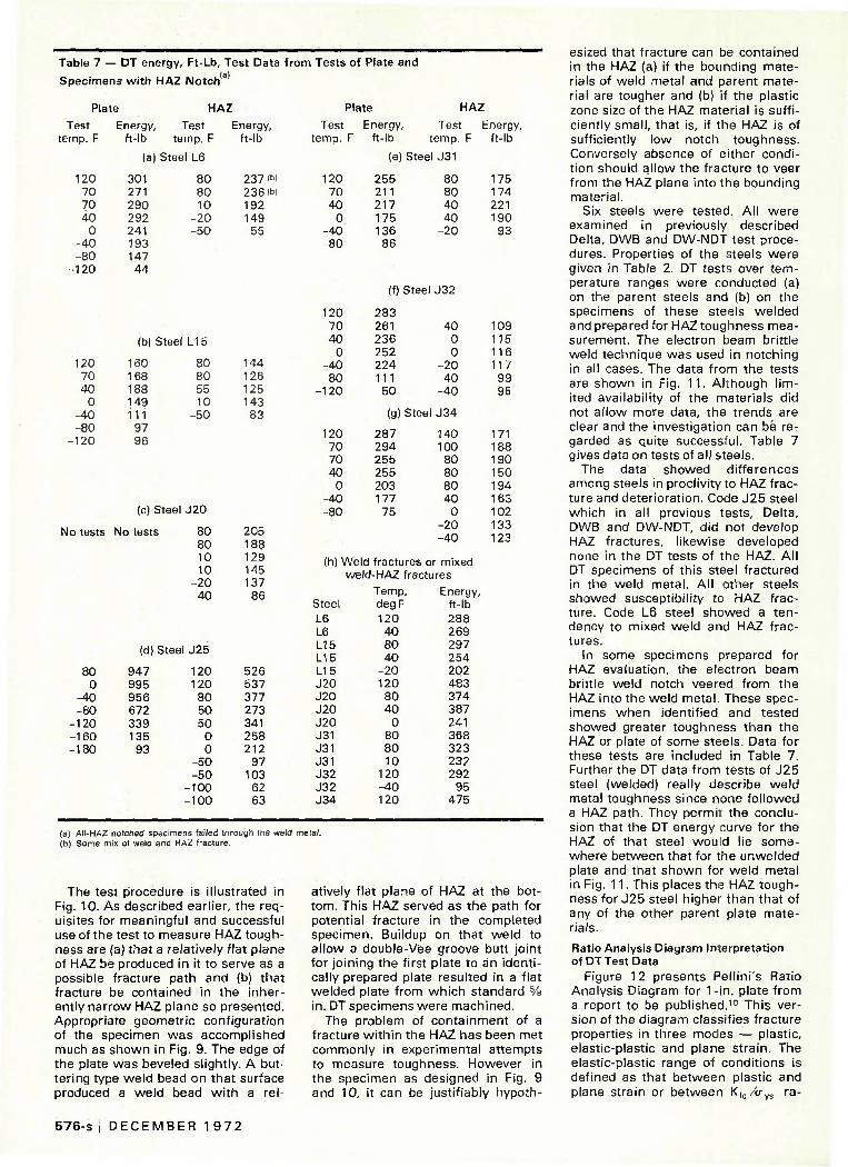
Table 7 — DT energy, Ft-Lb, Test Data from Tests of Plate and
Specimens with HAZ Notch c
Plate
Test Energy, imp. F ft-lb
(a) St
120 301 70 271 70 290 40 292
0 241
HAZ
Test Energy, temp. F ft-lb
eel L6
80 237 (W 80 236(b) 10 192
- 2 0 149 - 5 0 55
120 70 40
0 - 4 0 - 8 0 120
(b) Steel L15
160 168 188 149 111
97 96
80 80 55 10
- 5 0
144 126 125 143
83
(c) Stee
No tests No tests
1 J20
80 80 10 10
- 2 0 - 4 0
205 188 129 145 137
86
80 0
- 4 0 - 8 0 120 160 180
(d) Steel J25
947 995 956 672 339 135
93
120 120
80 50 50
0 0
- 5 0 - 5 0
- 1 0 0 - 1 0 0
526 537 377 273 341 258 212
97 103
62 63
Plate HAZ
Test Energy, Test temp. F ft- lb temp. F
(e) Steel J31
Energy, ft- lb
120 70 40
0 - 4 0 - 8 0
120 70 40
0 - 4 0 - 8 0 120
120 70 70 40
0 -40 - 8 0
255 211 217 175 136
86
80 80 40 40
- 2 0
(f) Steel J 3 2
283 261 236 252 224 111
50
40 0 0
- 2 0 - 4 0 - 4 0
(g) Steel J 3 4
287 294 255 255 203 177
75
140 100
80 80 80 40
0 - 2 0 - 4 0
175 174 221 190
93
109 115 116 117
99 95
171 188 190 150 194 163 102 133 123
(h) Weld fractures or mixed weld-HAZ fractures
Steel
L6 L6 L15 L15 L15 J20 J20 J20 J20 J31 J31 J31 J32 J32 J34
Temp, degF
120 40 80 40
- 2 0 120
80 40
0 80 80 10
120 - 4 0 120
Energy, ft-lb 288 269 297 254 202 483 374 387 241 368 323 232 292
95 475
(a) All-HAZ notched specimens failed through the weld metal. (b) Some mix ot weld and HAZ fracture.
The test procedure is illustrated in Fig. 10. As described earlier, the requisites for meaningful and successful use of the test to measure HAZ toughness are (a) that a relatively f lat plane of HAZ be produced in it to serve as a possible fracture path and (b) that fracture be contained in the inherently narrow HAZ plane so presented. Appropriate geometric configuration of the specimen was accomplished much as shown in Fig. 9. The edge of the plate was beveled slightly. A buttering type weld bead on that surface produced a weld bead w i th a rel
atively flat plane of HAZ at the bottom. This HAZ served as the path for potential fracture in the completed specimen. Buildup on that weld to al low a double-Vee groove butt joint for joining the first plate to an identically prepared plate resulted in a flat welded plate from which standard % in. DT specimens were machined.
The problem of containment of a fracture wi th in the HAZ has been met commonly in experimental attempts to measure toughness. However in the specimen as designed in Fig. 9 and 10, it can be justif iably hypoth
esized that fracture can be contained in the HAZ (a) if the bounding materials of weld metal and parent material are tougher and (b) if the plastic zone size of the HAZ material is sufficiently small, that is, if the HAZ is of sufficiently low notch toughness. Conversely absence of either condit ion should al low the fracture to veer from the HAZ plane into the bounding material.
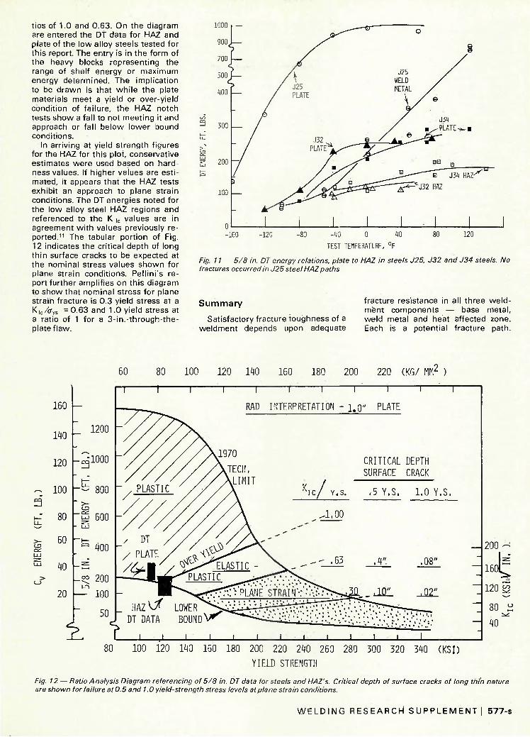
Six steels were tested. All were examined in previously described Delta, DWB and DW-NDT test procedures. Properties of the steels were given in Table 2. DT tests over temperature ranges were conducted (a) on the parent steels and (b) on the specimens of these steels welded and prepared for HAZ toughness measurement. The electron beam brittle weld technique was used in notching in all cases. The data f rom the tests are shown in Fig. 1 1 . Although l imited availability of the materials did not al low more data, the trends are clear and the investigation can be regarded as quite successful. Table 7 gives data on tests of all steels.
The data showed di f ferences among steels in proclivity to HAZ fracture and deterioration. Code J25 steel which in all previous tests, Delta, DWB and DW-NDT, did not develop HAZ fractures, likewise developed none in the DT tests of the HAZ. A l l DT specimens of this steel fractured in the weld metal. All other steels showed susceptibility to HAZ fracture. Code L6 steel showed a tendency to mixed weld and HAZ fractures.
In some specimens prepared for HAZ evaluation, the electron beam brittle weld notch veered from the HAZ into the weld metal. These specimens when identif ied and tested showed greater toughness than the HAZ or plate of some steels. Data for these tests are included in Table 7. Further the DT data from tests of J25 steel (welded) really describe weld metal toughness since none fol lowed a HAZ path. They permit the conclusion that the DT energy curve for the HAZ of that steel would lie somewhere between that for the unwelded plate and that shown for weld metal in Fig. 11 . This places the HAZ toughness for J25 steel higher than that of any of the other parent plate materials.
Ratio Analysis Diagram Interpretation of DT Test Data
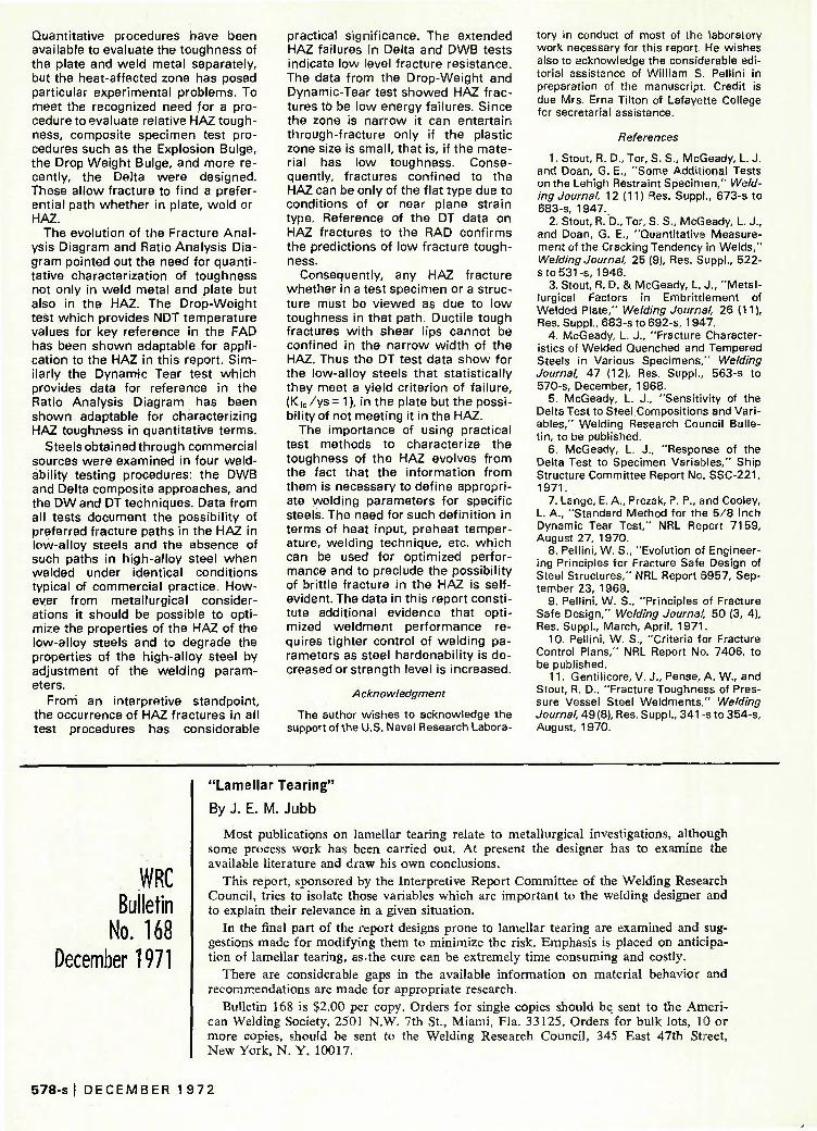
Figure 12 presents Pellini's Ratio Analysis Diagram for 1-in. plate from a report to be published.10 This version of the diagram classifies fracture properties in three modes — plastic, elastic-plastic and plane strain. The elastic-plastic range of conditions is defined as that between plastic and plane strain or between K*.c/ijvs ra-
576-s I D E C E M B E R 1 9 7 2
tios of 1.0 and 0,63. On the diagram are entered the DT data for HAZ and plate of the low alloy steels tested for this report. The entry is in the form of the heavy blocks representing the range of shelf energy or maximum energy determined. The implication to be drawn is that whi le the plate materials meet a yield or over-yield condition of failure, the HAZ notch tests show a fall to not meeting it and approach or fall below lower bound conditions.
In arriving at yield strength figures for the HAZ for this plot, conservative estimates were used based on hardness values. If higher values are estimated, it appears that the HAZ tests exhibit an approach to plane strain conditions. The DT energies noted for the low alloy steel HAZ regions and referenced to the K |C values are in agreement wi th values previously reported.1 ' The tabular portion of Fig. 12 indicates the critical depth of long th in surface cracks to be expected at the nominal stress values shown for plane strain conditions. Pellini's report further amplifies on this diagram to show that nominal stress for plane strain fracture is 0.3 yield stress at a Kic/tfys = 0.63 and 1.0 yield stress at a ratio of 1 for a 3-in.-through-the-platef law.
W, 200 - /
-10 0 40
TEST TEMPERATURF, °F
Fig. 11 — 5/8 in. DT energy relations, plate to HAZ in steels J25, J32 and J34 steels. No fractures occurred in J25 steel HAZ paths
S u m m a r y
Satisfactory fracture toughness of a weldment depends upon adequate
fracture resistance in all three weldment components — base metal, weld metal and heat affected zone. Each is a potential fracture path.
>-Cd
>
100 120 W O 160 180 200 220 240 260 280 300 320 340 (KSI)
YIELD STRENGTH
Fig. 12 — Ratio Analysis Diagram referencing of 5/8 in. DT data for steels and HAZ's. Critical depth of surface cracks of long thin nature are shown for failure at 0.5 and 1.0 yield-strength stress levels at plane strain conditions.
W E L D I N G R E S E A R C H S U P P L E M E N T I 577-s
Quantitative procedures have been available to evaluate the toughness of the plate and weld metal separately, but the heat-affected zone has posed particular experimental problems. To meet the recognized need for a procedure to evaluate relative HAZ toughness, composite specimen test procedures such as the Explosion Bulge, the Drop Weight Bulge, and more recently, the Delta were designed. These allow fracture to f ind a preferential path whether in plate, weld or HAZ.
The evolution of the Fracture Anal ysis Diagram and Ratio Analysis Diagram pointed out the need for quantitative characterization of toughness not only in weld metal and plate but also in the HAZ. The Drop-Weight test which provides NDT temperature values for key reference in the FAD has been shown adaptable for application to the HAZ in this report. Similarly the Dynamic Tear test which provides data for reference in the Ratio Analysis Diagram has been shown adaptable for characterizing HAZ toughness in quantitative terms.
Steels obtained through commercial sources were examined in four weldability testing procedures: the DWB and Delta composite approaches, and the DW and DT techniques. Data from all tests document the possibil ity of preferred fracture paths in the HAZ in low-alloy steels and the absence of such paths in high-alloy steel when welded under identical conditions typical of commercial practice. However from metallurgical considerations it should be possible to optimize the properties of the HAZ of the low-alloy steels and to degrade the properties of the high-alloy steel by adjustment of the welding parameters.
From an interpretive standpoint, the occurrence of HAZ fractures in all test procedures has considerable
practical significance. The extended HAZ failures in Delta and DWB tests indicate low level fracture resistance. The data from the Drop-Weight and Dynamic-Tear test showed HAZ fractures to be low energy failures. Since the zone is narrow it can entertain through-fracture only if the plastic zone size is small , that is, if the material has low toughness. Consequently, fractures confined to the HAZ can be only of the flat type due to conditions of or near plane strain type. Reference of the DT data on HAZ fractures to the RAD confirms the predictions of low fracture toughness.
Consequently, any H.AZ fracture whether in a test specimen or a structure must be viewed as due to low toughness in that path. Ductile tough fractures wi th shear lips cannot be confined in the narrow width of the HAZ. Thus the DT test data show for the low-alloy steels that statistically they meet a yield criterion of failure, (K | C / ys= 1), in the plate but the possibility of not meeting it in the HAZ.
The importance of using practical test methods to characterize the toughness of the HAZ evolves from the fact that the information from them is necessary to define appropriate welding parameters for specific steels. The need for such definit ion in terms of heat input, preheat temperature, welding technique, etc. which can be used for optimized performance and to preclude the possibility of brittle fracture in the HAT. is self-evident. The data in this report constitute additional evidence that optimized weldment performance requires tighter control of welding parameters as steel hardenabil ity is decreased or strength level is increased.
Acknowledgment
The author wishes to acknowledge the support of the U.S. Naval Research Labora
tory in conduct of most of the laboratory work necessary for this report He wishes also to acknowledge the considerable editorial assistance of William S, Pellini in preparation of the manuscript. Credit is due Mrs. Erna Tilton of Lafayette College for secretarial assistance.
References
1. Stout, R. D., Tor, S. S., McGeady, L. J. and Doan, G. E., "Some Additional Tests on the Lehigh Restraint Specimen," We/ding Journal, 12 (11) Res. Suppl., 673-s to 683-s, 1 947.
2. Stout, R. D., Tor, S. S., McGeady, L. J., and Doan, G. E., "Quantitative Measurement of the Cracking Tendency in Welds," Welding Journal, 25 (9), Res. Suppl., 522-sto531-s, 1946.
3. Stout, R. D. & McGeady, L. J., "Metallurgical Factors in Embrittlement of Welded Plate," Welding Journal, 26 (11), Res. Suppl., 683-s to 692-s, 1947.
4. McGeady, L. J., "Fracture Characteristics of Welded Quenched and Tempered Steels in Various Specimens," Welding Journal, 47 (12), Res. Suppl., 563-s to 570-s, December, 1968.
5. McGeady, L. J., "Sensitivity of the Delta Test to Steel Compositions and Variables," Welding Research Council Bulletin, to be published.
6. McGeady, L. J., "Response of the Delta Test to Specimen Variables," Ship Structure Committee Report No. SSC-221, 1971.
7. Lange, E. A., Prezak, P. P., and Cooley, L. A., "Standard Method for the 5/8 Inch Dynamic Tear Test," NRL Report 7159, August 27, 1970.
8. Pellini, W. S., "Evolution of Engineering Principles for Fracture Safe Design of Steel Structures," NRL Report 6957, September 23, 1969.
9. Pellini, W. S., "Principles of Fracture Safe Design," Welding Journal, 50 (3, 4), Res. Suppl., March, April, 1971.
10. Pellini, W. S., "Criteria for Fracture Control Plans," NRL Report No. 7406, to be published.
11. Gentilicore, V. J., Pense, A. W., and Stout, R. D., "Fracture Toughness of Pressure Vessel Steel Weldments" Welding Journal, 49(8), Res. Suppl., 341 -s to 354-s, August, 1970.
WRC Bulletin
No. 168 December 1971
"Lamellar Tearing"
By J. E. M. Jubb
Most publications on lamellar tearing relate to metallurgical investigations, although some process work has been carried out. At present the designer has to examine the available literature and draw his own conclusions.
This report, sponsored by the Interpretive Report Committee of the Welding Research Council, tries to isolate those variables which are important to the welding designer and to explain their relevance in a given situation.
In the final part of the report designs prone to lamellar tearing are examined and suggestions made for modifying them to minimize the risk. Emphasis is placed on anticipation of lamellar tearing, as the cure can be extremely time consuming and costly.
There are considerable gaps in the available information on material behavior and recommendations are made for appropriate research.
Bulletin 168 is $2.00 per copy. Orders for single copies should be. sent to the American Welding Society, 2501 N.W. 7th St., Miami, Fla. 33125. Orders'for bulk lots, 10 or more copies, should be sent to the Welding Research Council, 345 East 47th Street, New York, N. Y. 10017.
578-s I D E C E M B E R 1 9 7 2
Recommended