1 Afrox Product Reference Manual
Wel
ding
Con
sum
able
s
Welding Consumables | Carbon Steels |
12
Section 12 - Welding Consumables 1
Carbon Steels 1
Welding of Carbon Steels 2
MMA Electrodes 24
MIG/MAG Wires 44
MIG & TIG Wires for CMn & Low Alloy Steels 50
Flux & Metal Cored Wires 53
Cored Wires for CMn & Low Alloy Steels 62
Subarc Wires & Fluxes 65
Submerged Arc Fluxes 70
Submerged Arc Wire & Flux Combinations 73
Oxy-Fuel & Gas Welding Rods 76
| Carbon Steels12

2Afrox Product Reference Manual
Wel
ding
Con
sum
able
s
| Welding Consumables | Carbon Steels
12
Weldability of SteelWeldability is a term used to describe the relative ease or difficulty with which a metal or alloy can be welded. The better the weldability, the easier it is to weld. However, weldability is a complicated property, as it encompasses the metallurgical compatibility of the metal or alloy with a specific welding process, its ability to be welded with mechanical soundness, and the capacity of the resulting weld to perform satisfactorily under the intended service conditions.
Before attempting to weld any material, it is essential to know how easy it is to weld and to be aware of any problems that might arise. One of the main problems likely to be encountered when welding carbon and alloy steels is hydrogen cracking. For hydrogen cracking to occur, it is necessary to have a supply of hydrogen to the weld and a heat affected zone (HAZ), a susceptible hardened microstructure, and tensile stress. If any one of these three components is eliminated, then hydrogen cracking will not happen. Solidification cracking and lamellar tearing are other potential problems associated with welding steel.
The main problem when welding steel is hardenability. As long as the steel contains sufficient carbon when it is cooled rapidly from high temperature, a phase transformation takes place. The phase transformation from austenite to martensite causes the material to harden and become brittle. It is then liable to crack on cooling, due to restraint, or later under the action of hydrogen.
Variation in temperature from the centre of the weld to the base material
The weldability of steel depends primarily on its hardenability and this, in turn, depends largely on its composition (most importantly its carbon content). Steels with carbon content under 0,3% are reasonably easy to weld, while steels with over 0,5% are difficult. Other alloying elements that have an effect on the hardenability of steel, but to a much lesser extent than carbon, are manganese, molybdenum, chromium, vanadium, nickel and silicon. These, together with carbon, are all generally expressed as a single value (the carbon equivalent). The higher the carbon equivalent, the higher the hardenability, the more difficult the steel is to weld, and the more susceptible the microstructure is likely to be to hydrogen cracking.
This effect can be overcome by preheat combined with the use of a low hydrogen process or low hydrogen welding consumables. Calculation of preheat is usually based on carbon equivalent (derived from steel composition), combined thickness of the components, and heat input from the welding process. It also takes account of the amount of hydrogen likely to be introduced into the weld metal by the welding process. If welding under high restraint, extra preheat may need to be applied. Some high carbon steels and low alloy steels may also need a post weld stress relief or tempering.
Hardenability and Hardness
To become harder, steel must undergo a phase change. The starting point is austenite, so the steel must first be heated into the austenitic temperature range (see diagram on left).
Austenite, quenched rapidly, will be transformed into martensite, a hard but brittle phase.
A slower cooling rate will promote formation of bainite and/or other softer phases.
Cooled even more slowly, a soft structure of ferrite plus cementite, called perlite, results.
Martensite, tempered martensite and heavily tempered martensite
Hardenability
Hardenability is the potential for any particular steel to harden on cooling and, as the carbon content of the steel increases towards 0,8%, so the potential of the steel to harden increases. Increasing the alloy content of the steel also increases the hardenability.
While hardness and strength may be desirable in a welded steel structure, martensite can be brittle and susceptible to cracking, and it should be noted that the potential brittleness of the material also increases as hardenability increases.
Hardenability describes the potential of steel to form hard microstructures. What hardness is actually achieved in steel with known hardenability depends on the maximum temperature to which it is heated and the cooling rate from that temperature. During welding, the parent material close to the weld will be heated to temperatures near melting point, while further away it will remain at ambient temperature. The cooling rate depends on the mass of material, its temperature, and the welding heat input. Therefore, when welding any given hardenable steel, the hardness in the HAZ depends on the cooling rate – the faster the cooling rate, the harder the microstructure produced and the more susceptible it is to cracking.
Liquid
Austenite
Iron carbon equilibrium diagram
Ferrite + Cementile
0,2% Carbon
Temperature distribution across half the weld
d
cb
a
Welding of Carbon Steels
Back to contents

3 Afrox Product Reference Manual
Wel
ding
Con
sum
able
s
Welding Consumables | Carbon Steels |
12
After welding, the hardness in the HAZ may range from less than 300 HV to more than 550 HV, depending on the parent steel composition and the other factors described above. As the hardness of the HAZ increases, so does its susceptibility to hydrogen cracking. However, as a rule of thumb, if the maximum hardness in the HAZ is maintained below 350 HV, then hydrogen cracking will be avoided.
Carbon Equivalent
Carbon has the greatest effect on the hardenability of steel, but other alloying elements may be added to increase its hardenability. The addition effectively reduces the critical cooling rate and the temperature at which the austenite to martensite transformation takes place, making it easier for martensite to form at slower cooling rates.
Alloying elements that have the greatest influence on the hardenability of steel are manganese, molybdenum, chromium, vanadium, nickel, copper and silicon, but they have a much smaller effect than carbon.
The effect of these elements on the tendency to form HAZ martensite, and hence the likelihood of hydrogen cracking, is expressed conveniently as a carbon equivalent (CE). This basically describes the influence of each element on hardenability in terms of the effect that carbon has. There have been many different formulae derived to express carbon equivalent, but the one quoted here is the International Institute of Welding (IIW) equation that is applicable to carbon steel and is widely used:
Carbon equivalent (CE) =
%C +%Mn
+(%Ni + %Cu)
+(%Cr + %Mo + %V)
6 15 5
The equation is only valid for certain maximum percentages of each element and these percentages can be found in the technical literature.
The carbon equivalent is used mainly for estimating preheat. Preheat is necessary to slow down the cooling rate sufficiently to reduce hardening in the HAZ of welds in susceptible carbon and low alloy steels. This, in turn, helps to prevent subsequent HAZ hydrogen cracking. The overall effect is to improve the weldability of the steel being welded, or at least to overcome the weldability problems presented by it.
CE is calculated from the composition of the steel in question and is used – together with welding heat input, potential hydrogen from the consumable, and combined thickness, or by reference to published data – to determine the preheat. It is recommended that the actual composition of the steel is
used to ensure accuracy of calculation of CE, but nominal or maximum specified compositional data may be used when this is unavailable. The use of nominal composition obviously carries some risk that CE will be underestimated and too low preheat will be used, with potential cracking problems.
Weldability
Weldability describes the relative ease or difficulty with which a metal or alloy can be welded.
The relative weldability of carbon and low alloy steels are summarised here.
As has already been stated, weldability varies with the chemistry of the steel, particularly with reference to its carbon content.
The majority of carbon steels are weldable, but some grades have better weldability and, therefore, are more easily welded than others. As the carbon content increases, weldability tends to decrease as the hardenability increases and the steel becomes more prone to cracking.
Low carbon steels containing <0,15% carbon and <0,6% manganese generally have good weldability, as the composition is too lean to give any significant hardening effect during welding. However, steels with <0,12% carbon and low levels of manganese can be prone to porosity, although they are not susceptible to hydrogen cracking.
Steels with carbon contents between 0,15 and 0,3% carbon and up to 0,9% manganese, have good weldability, particularly those with carbon content below 0,22%. These are mild steels and rarely present problems, as long as impurity levels are kept low. They are all weldable without preheat, using any of the common welding processes. Those at the top end of the composition range, above about 0,25% carbon, may be prone to cracking under certain circumstances. They may be welded using any of the common welding processes, but are best welded with a low hydrogen process such as MIG or low hydrogen consumables. Thick sections may require preheating to reduce the cooling rate.
Medium carbon steels containing between 0,25 and 0,5% carbon, with generally <1% manganese, are hardenable by heat treatment and so are prone to cracking when welded. They can be welded, but require suitable welding procedures, specifying preheat and interpass temperature control to account for the carbon content or carbon equivalent and the combined thickness of the joint being produced. These steels should always be welded using a low hydrogen welding process or controlled hydrogen consumables.
Steels with even higher carbon levels, between 0,5 and 1,0%, with <1% manganese, are used where their higher hardness and strength can be exploited. However, their high hardenability means that they have poor weldability and are difficult to weld without cracking. They are generally welded in the hardened condition and so require preheating, interpass temperature control and post weld stress relief to give any chance or avoiding cracking. Low hydrogen processes, such as MIG and TIG welding or low hydrogen consumables, such as low hydrogen MMA electrodes will always be required when welding these steels.
Carbon-manganese steels have carbon typically between 0,15 and 0,5%, and manganese levels between 1,0 and 1,7%. For structural purposes, carbon is normally held below 0,3%, manganese not above 1,2% and sulphur and phosphorous are required to be below 0,05%. Generally, they are weldable,

4Afrox Product Reference Manual
Wel
ding
Con
sum
able
s
| Welding Consumables | Carbon Steels
12
although some will require controls on preheat and heat input. Those at the higher end of the carbon range also benefit from the use of low hydrogen welding processes or controlled hydrogen consumables.
Structural steels often have limits imposed on maximum carbon equivalent to ensure good weldability and ease of welding for the fabricator.
Weldable high strength low alloy (HSLA) steels have weldability similar to the low carbon steels, and so do not usually present problems.
Most quenched and tempered steels can be welded, but they rely on relatively high cooling rates for the strong martensitic structures to form. Careful control of preheat, heat input and interpass temperature is required to achieve the correct structure without cracking. Welding must be carried out using a low hydrogen process, or hydrogen-controlled consumables, and welding procedures need to be tested and approved.
Weld and HAZ Cracking
With steel, poor weldability often manifests in a reduction of the resistance of the steel to cracking after welding.
Base metalHeat affected zoneWeldmetal
The main causes of cracking in steel are:
High levels of carbon and other alloy elements, resulting in brittle zones around the weld.
High cooling rates after welding increasing the hardness, which increases the susceptibility to cold cracking.
Joint restraint preventing contraction after welding, leading to cracking.
Hydrogen in the weld bead or HAZ, leading to hydrogen- induced cold cracking.
Contaminants like sulphur and phosphorous, resulting in solidification cracking.
Lamellar tearing due to inclusions layering during rolling, resulting in deterioration of the through-thickness properties.
The most common cause of cracking in steel is the presence of hydrogen. Hydrogen (or cold) cracking is usually considered the most serious potential problem with modern steels. Hydrogen cracking is most frequently a HAZ phenomenon, but it can also occur in weld metal, particularly in high alloy steels. Hydrogen, like carbon, is more soluble in austenite than ferrite and can easily be picked up by the weld metal. When ferrite is formed as the material cools, hydrogen solubility decreases and hydrogen diffuses to the HAZ, where it becomes trapped and can cause crack propagation.
Heat affected zone (cold cracking)
There are published guidelines and standards that contain welding procedures to avoid hydrogen cracking. For hydrogen cracking to occur, it is necessary to have a supply of hydrogen to the weld and HAZ, a susceptible hardened microstructure, and tensile stress. If any one of these three components is eliminated, then hydrogen cracking will not happen.
To avoid cold cracking, the following points should be noted:
The lower the carbon equivalent, the lower the potential for cracking.
Limit the hydrogen content of weld metal and HAZ by using a low hydrogen process or low hydrogen consumables.
Keep joint restraint to a minimum by careful joint design.
Reduce the cooling rate of the weld area by preheat and suitable welding heat input.
Eliminating hydrogen after the weld is completed by keeping the weld hot (hydrogen release treatment).
Ensure impurities are kept at a low level.
The above guide is of a very general nature. If in doubt, seek expert technical advice.
Factors Influencing Weldability
In terms of avoiding weldability problems, particularly hydrogen cracking, when welding carbon or low alloy steels, there are several factors that demand consideration. These include the amount of hydrogen generated by the welding process or consumable, the heat input into the weld, the combined thickness (heat sink) of the joint, and the level of preheat applied to the components prior to welding. Joint configuration and restraint are also important factors when considering weldability.
Process Hydrogen
One of the three key components necessary for hydrogen cracking is a source of hydrogen. During welding, the most likely sources of hydrogen are the welding consumables or contaminants on the parent material. Here we consider hydrogen from the welding process and consumables only.
The amount of hydrogen put into the weld will vary from one welding process to another and may also vary within a process from one consumable type to another. The risk of hydrogen cracking increases as the amount of hydrogen from the process or consumable gets larger.
Solid wire processes, such as MIG and TIG, are capable of giving hydrogen levels below 5 ml/100 g of weld metal. These are generally thought to be low hydrogen processes, provided the MIG wire is clean.

5 Afrox Product Reference Manual
Wel
ding
Con
sum
able
s
Welding Consumables | Carbon Steels |
12
The manual metal arc process can give a wide range of hydrogen levels, from well over 15 ml/100 g of weld metal (with cellulosic and rutile coated electrodes) to less than 5 ml /100 g of weld metal (with basic coated electrodes) given the appropriate baking or re-drying treatment.
The potential hydrogen levels can vary with product type for cored wire welding processes too. Basic type flux cored wires may be capable of getting below 5 ml/100 g of weld metal, but rutile cored and metal cored wire types may give 10 or 15 ml/100 g of weld metal. Some recent developments have enabled metal cored and rutile cored wire to achieve hydrogen levels below 10 ml/100 g, with some even below 5 ml/100 g.
Submerged arc wires, like MIG wires, should be able to give low levels of hydrogen but, when used in combination with different fluxes, the hydrogen level may vary between <5 to 15 ml/100 g of weld metal.
Welding Heat Input
The heat input from the welding process plays a major role in the heating and cooling cycles experienced by the weld and parent plate during welding. For a given plate thickness, a high heat input is likely to result in a slower cooling rate than a low heat input, and will therefore produce a softer microstructure in the HAZ that is less prone to hydrogen cracking. However, that does not mean that welding should always be carried out with a high heat input, because this brings with it other problems, such as loss of mechanical properties and an increased risk of solidification cracking. So it is necessary to select a heat input to give a sound weld with the desired mechanical properties and to use preheat to exert control of the cooling rate.
Heat input ‘Q’ may be calculated as:
Q =k x V x I x 60
kJ/mmS x 1 000
where ‘V’ is arc voltage (V), ‘I’ is welding current, and ‘S’ is welding speed in mm/min.
The value derived from this formula may be multiplied by a factor ‘k’, the thermal efficiency factor for the welding process, to give an energy input that takes the efficiency of the welding process into account. Typical thermal efficiency factors are:
‘k’ = 1,0 for submerged arc welding
‘k’ = 0,8 for MIG / MAG, MMA, flux cored and metal cored arc welding
‘k’ = 0,6 for TIG and plasma welding
For example, when MIG welding, the welding heat input formula becomes:
Q =0,8 x V x I x 60
kJ/mmS x 1 000
Welding heat input will vary with process and consumable type and size. With small diameter electrodes, low current and fast welding speeds, heat inputs below 1,0 kJ/mm are readily attained. With large diameter electrodes, high currents and slower welding speeds, heat inputs in excess of 6,0 kJ/mm can be reached.
Note that a weld made using a stringer bead technique will have a lower heat input than a weld made with the same size electrode at the same current but using a weave bead technique.
Combined Thickness
The cooling rate of plate in the region of a weld depends on the thickness of the plates in the joint, the number of plates meeting at the joint, the amount of heat put into the weld area, and the initial temperature of these plates. Cooling occurs by conduction and so the greater the heat sink, the faster the cooling rate. Therefore, other factors being constant, the thicker the plate, the greater the potential for rapid cooling, and so the greater the likelihood of hardening in the HAZ of susceptible steels.
Estimates of preheat will normally take into account the thickness of each of the components in the joint to allow for the cooling effect. The thickness of each component is added together to give what is normally referred to as ‘combined thickness’ (CT).
How the combined thickness is derived depends on the joint configuration and is illustrated below:
CT = T1 + T2 + T3 …
Example of combined thickness calculation for butt joint
T1 T2
Example of combined thickness calculation for fillet joint
T3
T1 T2
For butt welds, the CT equals the sum of the thicknesses of the two plates being welded; for fillet welds, the CT equals twice the thickness of the base plate plus the thickness of the up-stand. Therefore, for a given plate thickness, a fillet joint has a faster cooling rate than a butt joint.

6Afrox Product Reference Manual
Wel
ding
Con
sum
able
s
| Welding Consumables | Carbon Steels
12
Recommendations for the Storage, Handling and Treatment of Afrox Hydrogen Controlled Basic Carbon Steel ElectrodesHandling
Afrox electrodes are packed in cardboard cartons with a moisture resistant polythene wrapping. Further protection is provided by shrinking these rigid cartons into packs of three.
The packs are stacked to a maximum of eight high on wooden pallets.
This is the recommended maximum height to avoid crushing and hence possible damage during storage.
Storage
Basic low hydrogen electrodes should be stored in dry conditions, off the floor on pallets or racks in their unopened containers. The rate of moisture re-absorption which takes place is determined by the resistance of the electrode to the atmospheric conditions of relative humidity and temperature prevailing during storage.
Storage is not really the most important issue in determining subsequent weld metal hydrogen content of low hydrogen electrodes, but rather, the rate at which moisture is lost during re-baking of electrodes prior to use.
Storage under the correct conditions will provide indefinite product shelf-life.
Re-baking
It is essential that hydrogen-controlled electrodes be re-baked prior to use. The re-baking temperature recommendations depend on the maximum permissible hydrogen content tolerable in the deposited weld metal and the hardenability of the parent material.
Standard Re-baking Temperatures
Product 5-10 ml H2/ 100 g
<5 ml H2/100 g
7018-1 350 - 370°C –
78MR 250 - 270°C 370 - 400°C
Ferron 1 350 - 370°C –
Baking time one-two hours
Diffusible hydrogen content determined using Yanaco gas chromatograph
Optimum conditions for re-baking are achieved when electrodes are placed on the oven shelves not more than five deep. This is normally only required when diffusible hydrogen contents of less than 5 ml H2/100 g of weld metal are specified and hardenable materials in thick sections have to be welded.
For general shop conditions, the electrode pile in the oven can be increased provided consumables in the centre of the pile achieve the minimum re-baking temperature for a minimum period of one hour.
Note: When electrodes are placed in a baking oven, the temperature in the electrode pile rises far more slowly than it takes for the oven’s own temperature to rise to the
set temperature. It is therefore incorrect to take the oven temperature as an accurate indication of the actual baking temperature reached by the electrodes and hence a guide to the time at temperature.
Unless the temperature during baking is timed on the basis of the electrode temperature, the electrodes cannot be considered properly re-baked prior to use.
If possible, it is recommended that fabricators carry out checks on their re-drying ovens to establish the correct conditions for actual electrode re-baking temperatures and times as compared to oven temperatures and times.
It is important to note that if the electrodes are maintained at the re-bake temperature for long periods of time, the coating may become brittle. Coating brittleness may also result if the electrode is re-baked above the maximum recommended temperature.
Number of Re-bakes
Repeated re-baking has an adverse effect on electrode coating strength and adhesion to the core wire. From tests carried out by Afrox, it is recommended that:
Re-baking at 370-400°C be limited to two times and re-baking at 250-270°C be limited to three times. (This does not include the factory bake).
Holding Conditions
Immediately after baking, the electrodes should be transferred to a holding oven alongside the baking oven. The recommended holding temperature is 150°C ± 20°C. The holding time is virtually indefinite with a working limit suggested as 120 hours. Any electrodes that are inadvertently exposed to excessive moisture, rain, etc. or are damaged, should be removed from the work site and destroyed.
Quivers
Electrodes drawn from holding ovens should be held in heated quivers at a minimum temperature of 75°C. The suggested period for the electrodes to remain in the quivers is eight hours. After this time, any remaining electrodes should be returned for re-baking.
General
In some instances, it may be possible to modify the above requirements, depending on the type of work which is being undertaken and technical requirements being imposed. Please refer any technical queries to the Marketing Department, Afrox Welding Consumables on (011) 490 0400.

7 Afrox Product Reference Manual
Wel
ding
Con
sum
able
s
Welding Consumables | Carbon Steels |
12
Preheating of Materials
What is Preheat?
A heating procedure applied to parent metal components immediately before welding commences, and considered as an essential part of the welding operation, is called ‘preheat’.
Preheating can be applied locally to the areas to be welded, or to the whole component. It is usually done to raise the temperature of the weld area so that the weld does not cool too quickly after welding. This protects the material being welded from the various adverse effects that can be caused by the normally rapid cooling cycle created by the welding process.
Note that, while preheat is applied before welding begins, it is essential that the minimum preheat temperature is maintained throughout the welding operation.
What Does Preheat Do?
Basically, preheat puts the parent metal components in a suitable condition for the subsequent welding operation. Preheating may be carried out for any of the following reasons:
Slow down the cooling rate
Reduce shrinkage stress and weld distortion
Promote fusion
Remove moisture.
Slow down the cooling rate
Some alloys (notably high carbon and low alloy steels), if welded and allowed to cool quickly, can develop hard or brittle phases in the heat affected zone (HAZ). These phases can render such alloys susceptible to cracking under the action of tensile shrinkage stresses as the weld area cools down, or they can result in low toughness of the HAZ.
Many steels are susceptible to hydrogen cracking, and fast cooling rates not only promote the formation of hard, susceptible microstructures but also lock the hydrogen into the solidifying weld metal. Because of this trapped hydrogen gas, pressure builds up in the weld and the heat affected zone, which can result in cracking of the already brittle microstructure. Such cracks are normally detected by post weld inspection techniques, but should they escape detection, they may lead to premature failure in service, with potentially disastrous consequences.
Preheating of components prior to welding in these situations is designed primarily to slow down the rate of cooling of the weldment. In reducing the cooling rate, preheat is protecting the parent metal by helping to prevent hardening of the weld by the formation of brittle phases. A softer, more ductile structure is more resistant to cracking. The slower cooling rate also gives more time for any hydrogen introduced into the weld to diffuse away from the welded joint.
Reduce shrinkage stress and weld distortion
If welds are made in highly restrained joints, or in materials with very low ductility (e.g. cast irons), the welding cycle of heating, followed by rapid cooling, can result in cracking in the weld or the surrounding area. This is due to the weld metal or adjacent parent metal not being able to withstand the effects of shrinkage stresses created by contraction.
Metals and Alloys that Should Not be Preheated
Preheat and high interpass temperatures can have a negative effect on the mechanical properties or corrosion resistance of some alloys. For example:
Austenitic manganese (13% Mn) steel
Austenitic stainless steels
Duplex stainless steels
Titanium alloys.

8Afrox Product Reference Manual
Wel
ding
Con
sum
able
s
| Welding Consumables | Carbon Steels
12
Here preheating is used to balance the thermal cycle and so reduce the shrinkage stresses in the weld and in the adjacent parent material.
When welding wrought materials in highly restrained joints, preheat is normally applied locally in the weld area.
When welding castings, the preheat applied may be ‘local’ (heating in the area of the weld only), ‘total’ (the whole casting is heated), or ‘indirect’ (heating a part of the casting away from the weld area to balance the effects of expansion and contraction).
Promote Fusion
Some alloy systems (e.g. copper and aluminium) have very high thermal conductivity, and if a weld is attempted on thick, cold plate, the parent material could chill the deposited weld metal so quickly that it does not fuse with the parent metal. This may be referred to as a ‘cold start’. The heat conduction away from the joint area can be such that a weld may be impossible using a conventional arc welding process.
Preheat is used in this case to raise the initial temperature of the material sufficiently to ensure full weld fusion from the start. This is particularly important when using a welding process / plate thickness combination that is likely to produce a cold start.
Remove Moisture
Any metallic components left overnight in a cold workshop or brought in from outside are likely to be damp or even wet. If they are welded in that condition, problems can arise in the resultant welds. For example, if the components are made of steel, then the moisture will act as a source of hydrogen and the result could be hydrogen cracking. Aluminium has a porous oxide layer, which will absorb moisture from the atmosphere, and, if not removed before welding, this can result in weld metal porosity and subsequent rejection of the weld.
While not normally the main objective of preheating, its use for removal of surface moisture prior to welding is not only advisable, but very often essential.
Carbon Steel and Alloy Steel
These two groups of materials have, quite rightly, been given more attention in estimation of preheat temperature than any other alloy system, as the penalty for getting it wrong can be severe.
The following list is intended only to give some indication of the level of preheat required for certain types of steel. In these examples, it is assumed that the weld is a butt weld, and the thicknesses given are the normally used ‘combined thickness’, where this is the total thickness of all the parts to be joined.
When calculating the ‘combined thickness’ of parts with varying thicknesses (such as forgings), the thickness of each part is usually averaged over a distance of 75 mm from the weld line. However, for some processes and materials, account must be taken of any difference of thickness beyond the 75 mm point, and it is important to refer to the specific welding procedures or relevant standards in each case.
Residual stresses present in a welded joint
Distortion due to the presence of residual stress

9 Afrox Product Reference Manual
Wel
ding
Con
sum
able
s
Welding Consumables | Carbon Steels |
12
Steel Type Combined Thickness (mm)
Typical Preheat (°C)
Low C and mild steels <50 50
>50 100 – 150
Medium C, CMn steels
<40 100 – 200
>40 150 – 250
High C, CMn steels All 200 – 300
QT steels, HSLA steels All None to 150 (max.)
0,5% Mo, 1% Cr-0,5% Mo steels*
All 100 – 250
2% Cr-1% Mo, 5% Cr-0,5% Mo steels*
All 200 – 300
Direct hardening steels
All 150 – 300
Case hardening steels
All 150
13% manganese steel
All None
*Preheat is usually specified by procedure and tightly monitored and controlled with these materials
It is recommended that more comprehensive documentation be consulted when selecting a temperature for a specific application.
Information to assist with calculation of preheat for CMn steels can be found in international standards (e.g. BS 5135 and AWS D1.1). These standards set out minimum preheat temperatures based on factors such as the type of steel specification or carbon equivalent, thickness, the welding process or heat input, and the hydrogen class of the welding consumable. The guidelines do not take restraint into consideration, so highly restrained joints may need higher levels of preheat than indicated.
The information in these standards is often used as a rough guide to determine preheat for low alloy steels. This should be done with extreme caution, as low alloy steels will frequently need much higher preheat than estimated by this means because of their alloy content.
When joining or surfacing hardenable steels (steels with high CE), it is sometimes possible to weld with an austenitic type consumable and to use a lower preheat than would be needed if ferritic consumables were to be used.
The decision-making process, when deciding whether to use preheat with carbon steel and alloy steel, can become quite complicated. Carbon and carbon-manganese steels and low alloy steels may require preheating, but this depends on their carbon equivalent, combined thickness and proposed welding heat input.
Preheat with these ferritic materials is primarily aimed at reducing the severity of the ‘quench’ after welding, and helping to prevent the formation of hard brittle microstructures in the weld and HAZ. It also allows hydrogen to diffuse away from the weld area, thus reducing the risk of hydrogen cracking. The objective is to keep the maximum HAZ hardness to below about 350 HV although this will not always be possible, particularly with some low alloy steels with high
hardenability. These low alloy types may, additionally, need a post weld heat treatment to restore properties.
How Much Preheat to Apply
The actual preheat temperature required for a specific welding operation depends not only on the material or materials being welded, but also the combined thickness of the joint, the heat input from the welding process being used, and the amount of restraint imposed upon the components. There are no hard and fast rules regarding how much preheat to apply, but there are many publications available that give helpful guidance.

10Afrox Product Reference Manual
Wel
ding
Con
sum
able
s
| Welding Consumables | Carbon Steels
12
Fundamentals of Manual Metal Arc (MMA) WeldingWelding Technique
Successful MMA welding depends on the following factors:
Selection of the correct electrode
Selection of the correct size of the electrode for the job
Correct welding current
Correct arc length
Correct angle of electrode to work
Correct travel speed
Correct preparation of work to be welded.
Electrode Selection
As a general rule, the selection of an electrode is straight-forward, in that it is only a matter of selecting an electrode of similar composition to the parent metal. However, for some metals there is a choice of several electrodes, each of which has particular properties to suit specific classes of work. Often, one electrode in the group will be more suitable for general applications due to its all round qualities.
The table below shows just a few of the range of electrodes available from Afrox, with their typical areas of application.
For example, the average welder will carry out most fabrication using mild steel and for this material has a choice of various standard Afrox electrodes, each of which will have qualities suited to particular tasks. For general mild steel work, however, Afrox Vitemax® electrodes will handle virtually all applications. Afrox Vitemax® is suitable for welding mild steel in all positions using AC or DC power sources. Its easy striking characteristics and the tolerance it has for work where fit-up and plate surfaces are not considered good, make it the most attractive electrode of its class.
Electrodes and Typical Applications
Name AWS Classification
Application
Afrox Vitemax® E6013 A premium quality electrode for general structural and sheet metal work in all positions, including vertical-down using low carbon steels
Afrox Afrolux E7024 An iron powder electrode for high speed welding of H-V fillets and flat butt joints. Medium to heavy structural applications in low carbon steels
Name AWS Classification
Application
Afrox 7018-1 E7018-1 A premium quality, all positional hydrogen-controlled electrode for carbon steels in pressure vessel applications and where high integrity welding is required; and for free-machining steels containing sulphur
Electrode Size
The size of the electrode generally depends on the thickness of the section being welded, and the thicker the section the larger the electrode required. In the case of light sheet, the electrode size used is generally slightly larger than the work being welded. This means that, if 2,0 mm sheet is being welded, 2,5 mm diameter electrode is the recommended size.
The following table gives the maximum size of electrodes that may be used for various thicknesses of section.
Recommended Electrode Sizes
Average Thickness of Plate or Section (mm)
Maximum Recommended Electrode Diameter (mm)
1,5 – 2,0 2,5
2,0 – 5,0 3,2
5,0 – 8,0 4,0
8,0 5,0
Welding Current
Correct current selection for a particular job is an important factor in arc welding. With the current set too low, difficulty is experienced in striking and maintaining a stable arc. The electrode tends to stick to the work, penetration is poor and beads with a distinct rounded profile will be deposited.
Excessive current is accompanied by overheating of the electrode. It will cause undercut and burning through of the material, and will give excessive spatter. Normal current for a particular job may be considered as the maximum, which can be used without burning through the work, over-heating the electrode or producing a rough spattered surface (i.e. the current in the middle of the range specified on the electrode package is considered to be the optimum).
In the case of welding machines with separate terminals for different size electrodes, ensure that the welding lead is connected to the correct terminal for the size electrode being used. When using machines with adjustable current, set on the current range specified. The limits of this range should not normally be exceeded. The following table shows the current ranges generally recommended for Vitemax®.

11 Afrox Product Reference Manual
Wel
ding
Con
sum
able
s
Welding Consumables | Carbon Steels |
12
Generally Recommended Current Range for Afrox Vitemax®
Electrode Size (mm) Current Range (A)
2,5 60 – 95
3,2 110 – 130
4,0 140 – 165
5,0 170 – 260
Arc Length
To strike the arc, the electrode should be gently scraped on the work until the arc is established. There is a simple rule for the proper arc length; it should be the shortest arc that gives a good surface to the weld. An arc too long reduces penetration, produces spatter and gives a rough surface finish to the weld. An excessively short arc will cause sticking of the electrode and rough deposits that are associated with slag inclusions.
For downhand welding, an arc length not greater than the diameter of the core wire will be most satisfactory. Overhead welding requires a very short arc, so that a minimum of metal will be lost. Certain Afrox electrodes have been specially designed for ‘touch’ welding. These electrodes may be dragged along the work and a perfectly sound weld is produced.
Electrode Angle
The angle that the electrode makes with the work is important to ensure a smooth, even transfer of metal.
The recommended angles for use in the various welding positions are covered later.
Correct Travel Speed
The electrode should be moved along in the direction of the joint being welded at a speed that will give the size of run required. At the same time, the electrode is fed downwards to keep the correct arc length at all times. As a guide for general applications, the table below gives recommended run lengths for the downhand position.
Correct travel speed for normal welding applications varies between approximately 100 and 300 mm per minute, depending on electrode size, size of run required and the amperage used.
Excessive travel speeds lead to poor fusion, lack of penetration, etc. while too slow a rate of travel will frequently lead to arc instability, slag inclusions and poor mechanical properties.
Run Length per Electrode – Afrox
Electrode Size (mm)
Electrode Length (mm)
Run Length (mm)
Min Max
4,0 350 175 300
3,2 350 125 225
2,5 350 100 225
Correct Work Preparation
The method of preparation of components to be welded will depend on equipment available and relative costs. Methods may include sawing, punching, shearing, machining, flame cutting and others.
In all cases, edges should be prepared for the joints that suit the application. The following section describes the various joint types and areas of application.
Types of Joints
Butt welds
A butt weld is a weld made between two plates so as to give continuity of section.
Close attention must be paid to detail in a butt weld to ensure that the maximum strength of the weld is developed. Failure to properly prepare the edges may lead to the production of faulty welds, as correct manipulation of the electrode is impeded.
Butt Welding
Weld faceReinforcement
Root faceRoot gap
Two terms relating to the preparation of butt welds require explanation at this stage. They are:
Root face: the proportion of the prepared edge that has not been bevelled (land).
Root gap: the separation between root faces of the parts to be joined.
Various types of butt welds are in common use and their suitability for different thickness of steel are described as follows:
Square Butt Weld
Weld beads
Layers
70˚ - 85˚
Weld beads
Layers
Electrode
SlagWeld pool
Weld metalArc
Direction of welding
The edges are not prepared, but are separated slightly to allow fusion through the full thickness of the steel. Suitable for plate up to 6 mm in thickness
Single ‘V’ Butt Weld
Weld beads
Layers
70˚ - 85˚
Weld beads
Layers
Electrode
SlagWeld pool
Weld metalArc
Direction of welding
This is commonly used for plate up to 16 mm in thickness and on metal of greater thickness where access is available from only one side
Double ‘V’ Butt Weld
Weld beads
Layers
70˚ - 85˚
Weld beads
Layers
Electrode
SlagWeld pool
Weld metalArc
Direction of welding
Used on plate of 12 mm and over in thickness when welding can be applied from both sides. It allows faster welding and greater economy of electrodes than a single ‘V’ preparation on the same thickness of steel and also has less tendency to distortion as weld contraction can be equalised
Butt Weld with Backing Material
Weld beads
Layers
70˚ - 85˚
Weld beads
Layers
Electrode
SlagWeld pool
Weld metalArc
Direction of welding
When square butt welds or single ‘V’ welds cannot be welded from both sides, it is desirable to use a backing bar to ensure complete fusion

12Afrox Product Reference Manual
Wel
ding
Con
sum
able
s
| Welding Consumables | Carbon Steels
12
Single ‘U’ Butt Weld
Weld beads
Layers
70˚ - 85˚
Weld beads
Layers
Electrode
SlagWeld pool
Weld metalArc
Direction of welding
Used on thick plates as an alternative to a single ‘V’ preparation. It has advantages in speed of welding. It takes less weld metal than a single ‘V’, there is less contraction and there is, therefore, a lessened tendency to distortion. Preparation is more expensive than in the case of a ‘V’, as machining is required. This type of joint is most suitable for material over 40 mm in thickness
Double ‘U’ Butt Weld
Weld beads
Layers
70˚ - 85˚
Weld beads
Layers
Electrode
SlagWeld pool
Weld metalArc
Direction of welding
For use on thick plate that is accessible for welding from both sides. For a given thickness it is faster, needs less weld metal and causes less distortion than a single ‘U’ preparation
Horizontal Butt Weld
Weld beads
Layers
70˚ - 85˚
Weld beads
Layers
Electrode
SlagWeld pool
Weld metalArc
Direction of welding
The lower member in this case is bevelled to approximately 15° and the upper member 45°, making an included angle of 60°. This preparation provides a ledge on the lower member, which tends to retain the molten metal
General notes on butt welds
The first run in a prepared butt weld should be deposited with an electrode not larger than 4,0 mm. The angle of the electrode for the various runs in a butt weld is shown opposite.
It is necessary to maintain the root gap by tacking at intervals or by other means, as it will tend to close during welding.
All single ‘V’, single ‘U’ and square butt welds should have a backing run deposited on the underside of the joint, otherwise 50% may be deducted from the permissible working stress of the joint.
Before proceeding with a run on the underside of a weld, it is necessary to back-gouge or grind that side of the joint.
Butt welds should be overfilled to a certain extent by building up the weld until it is above the surface of the plate. Excessive reinforcement, however, should be avoided.
In multi-run butt welds, it is necessary to remove all slag and surplus weld metal before a start is made on additional runs. This is particularly important with the first run, which tends to form sharp corners that cannot be penetrated with subsequent runs. Electrodes larger than 4,0 mm are not generally used for vertical or overhead butt welds.
The diagrams opposite indicate the correct procedure for welding thick plate when using multiple runs.
Bead Sequence for 1st and 2nd Layers
Weld beads
Layers
70˚ - 85˚
Weld beads
Layers
Electrode
SlagWeld pool
Weld metalArc
Direction of welding
Bead Sequence for Subsequent Layers
Weld beads
Layers
70˚ - 85˚
Weld beads
Layers
Electrode
SlagWeld pool
Weld metalArc
Direction of welding
Welding Progression Angle
3
81
74
6
2
1 Weld metal2 Workpiece3 Electrode4 Slag5 Welding direction6 70–85° angle7 Arc8 Weld pool
5
Fillet welds
A fillet weld is approximately triangular in section, joining two surfaces not in the same plane and forming a lap joint, ‘T’ joint or corner joint. Joints made with fillet welds do not require extensive edge preparation, as is the case with butt welded joints, since the weld does not necessarily penetrate the full thickness of either member. It is, however, important that the parts to be joined be clean, close fitting, and that all the edges on which welding is to be carried out are square. On sheared plate, it is advisable to entirely remove any ‘false cut’ on the edges prior to welding.

13 Afrox Product Reference Manual
Wel
ding
Con
sum
able
s
Welding Consumables | Carbon Steels |
12
Fillet welds are used in the following types of joints:
‘T’ Joints
A fillet weld may be placed either on one or both sides, depending on the requirements of the work. The weld metal should fuse into or penetrate the corner formed between the two members. Where possible, the joint should be placed in such a position as to form a ‘natural V’ fillet since this is the easiest and fastest method of fillet welding
Lap Joints
In this case, a fillet weld may be placed either on one or both sides of the joint, depending on accessibility and the requirements of the joint. However, lap joints, where only one weld is accessible, should be avoided where possible and must never constitute the joints of tanks or other fabrications where corrosion is likely to occur behind the lapped plates. In applying fillet welds to lapped joints, it is important that the amount of overlap of the plates be not less than five times the thickness of the thinner part. Where it is required to preserve the outside face or contour of a structure, one plate may be joggled
Corner Joints
The members are fitted as shown, leaving a ‘V’-shaped groove in which a fillet weld is deposited. Fusion should be complete for the full thickness of the metal. In practice, it is generally necessary to have a gap or a slight overlap on the corner. The use of a 1,0–2,5 mm gap has the advantage of assisting penetration at the root, although setting up is a problem. The provision of an overlap largely overcomes the problem of setting up, but prevents complete penetration at the root and should therefore be kept to a minimum (i.e. 1,0–2,5 mm)
The following terms and definitions are important in specifying and describing fillet welds.
Leg length
A fusion face of a fillet weld, as shown on the right.
Throat thickness
A measurement taken through the centre of a weld from the root to the face, along the line that bisects the angle formed by the members to be joined. Many countries use throat thickness rather than leg length.
Effective throat thickness is a measurement on which the strength of a weld is calculated. The effective throat thickness is based on a mitre fillet (concave fillet weld), which has a throat thickness equal to 70% of the leg length. For example, in the case of a 20 mm fillet, the effective throat thickness will be 14 mm.
Convex fillet weld
A fillet weld in which the contour of the weld metal lies outside a straight line joining the toes of the weld. A convex fillet weld of specified leg length has a throat thickness in excess of the effective measurement.
Convex Fillet Weld
12 3
4
4
5
5
6
1 Actual throat2 Effective throat3 Convexity4 Leg5 Size6 Theoretical throat
Concave fillet weld
A fillet in which the contour of the weld is below a straight line joining the toes of the weld. It should be noted that a concave fillet weld of a specified leg length has a throat thickness less than the effective throat thickness for that size fillet. This means that, when a concave fillet weld is used, the throat thickness must not be less than the effective measurement. This entails an increase in leg length beyond the specified measurement
Concave Fillet Weld
1 23
6
54
5
4
1 Actual throat2 Effective throat3 Concavity4 Leg5 Size6 Theoretical throat

14Afrox Product Reference Manual
Wel
ding
Con
sum
able
s
| Welding Consumables | Carbon Steels
12
The size of a fillet weld is affected by the electrode size, welding speed or run length, welding current and electrode angle. Welding speed and run length have an important effect on the size and shape of the fillet, and on the tendency to undercut.
Insufficient speed causes the molten metal to pile up behind the arc and eventually to collapse. Conversely, excessive speed will produce a narrow irregular run having poor penetration, and where larger electrodes and high currents are used, undercut is likely to occur.
Fillet weld data
Nominal Fillet Size (mm)
Min. Throat Thickness (mm)
Plate Thickness (mm)
Electrode Size (mm)
5,0 3,5 5,0 – 6,3 3,2
6,3 4,5 6,3 – 12,0 4,0
8,0 5,5 8,0 – 12,0 and over
5,0
10,0 7,0 10,0 and over 4,0
Selection of welding current is important. If it is too high, the weld surface will be flattened and undercut accompanied by excessive spatter is likely to occur. Alternatively, a current which is too low will produce a rounded narrow bead with poor penetration at the root. The first run in the corner of a joint requires a suitably high current to achieve maximum penetration at the root. A short arc length is recommended for fillet welding. The maximum size fillet which should be attempted with one pass of a large electrode is 8,0 mm. Efforts to obtain larger leg lengths usually result in collapse of the metal at the vertical plate and serious undercutting. For large leg lengths, multiple run fillets are necessary. These are built up as shown below. The angle of the electrode for various runs in a downhand fillet weld is also shown.
Recommended electrode angles for fillet welds
1st Run 2nd Run
3rd Run Multi-run Fillet
Multi-run (multi-pass) horizontal fillets have each run made using the same run lengths (Run Length per Electrode table). Each run is made in the same direction, and care should be taken with the shape of each, so that it has equal leg lengths and the contour of the completed fillet weld is slightly convex with no hollows in the face.
Vertical fillet welds can be carried out using the upwards or downwards technique. The characteristics of each are: Upwards – current used is low, penetration is good, surface is slightly convex and irregular. For multiple run fillets, large single-pass weaving runs can be used. Downwards – current used is medium, penetration is poor, each run is small, concave and smooth.
The downwards method should be used for making welds on thin material only. Electrodes larger than 4,0 mm are not recommended for vertical-down welding. All strength joints in vertical plates 10,0 mm thick or more should be welded using the upward technique. This method is used because of its good penetration and weld metal quality. The first run of a vertical-up fillet weld should be a straight sealing run made with 3,2 mm or 4,0 mm diameter electrode. Subsequent runs for large fillets may be either numerous straight runs or several wide weaving runs.
Correct selection of electrodes is important for vertical welding.
In overhead fillet welds, careful attention to technique is necessary to obtain a sound weld of good profile. Medium current is required for best results. High current will cause undercutting and bad shape of the weld, while low current will cause slag inclusions. To produce a weld having good penetration and of good profile, a short arc length is necessary. Angles of electrode for overhead fillets is illustrated below.
Recommended Electrode Angles for Overhead Fillet Welds
30˚15˚ 45˚

15 Afrox Product Reference Manual
Wel
ding
Con
sum
able
s
Welding Consumables | Carbon Steels |
12
Welding Defects and ProblemsManual metal arc welding, like other welding processes, has welding procedure problems that may develop and which can cause defects in the weld. Some defects are caused by problems with the materials. Other welding problems may not be foreseeable and may require immediate corrective action. A poor welding technique and improper choice of welding parameters can cause weld defects.
Defects that can occur when using the shielded metal arc welding process are slag inclusions, wagon tracks, porosity, wormhole porosity, undercutting, lack of fusion, overlapping, burn through, arc strikes, craters and excessive weld spatter. Many of these welding technique problems weaken the weld and can cause cracking. Other problems that can occur and which can reduce the quality of the weld are arc blow, finger nailing and improper electrode coating moisture contents.
Defects Caused by Welding Technique
Slag inclusions
Slag inclusions occur when slag particles are trapped inside the weld metal, which produces a weaker weld. These can be caused by:
Erratic travel speed
Too wide a weaving motion
Slag left on the previous weld pass
Too large an electrode being used
Letting slag run ahead of the arc.
This defect can be prevented by:
A uniform travel speed
A tighter weaving motion
Complete slag removal before welding
Using a smaller electrode
Keeping the slag behind the arc, which is done by shortening the arc, increasing the travel speed or changing the electrode angle.
Wagon tracks
Top view through transparent bead
Wagon tracks are linear slag inclusions that run the longitudinal axis of the weld. They result from allowing the slag to run ahead of the weld puddle and by slag left on the previous weld pass. These occur at the toe lines of the previous weld bead.
Porosity
Porosity is gas pockets in the weld metal that may be scattered in small clusters or along the entire length of the weld. Porosity weakens the weld in approximately the same way that slag inclusions do.
Porosity may be caused by:
Excessive welding current
Rust, grease, oil or dirt on the surface of the base metal
Excessive moisture in the electrode coatings
Impurities in the base metal
Too short an arc length, except when using low hydrogen or stainless steel electrodes
Travel speed too high, which causes freezing of the weld puddle before gases can escape.
This problem can be prevented by:
Lowering the welding current
Cleaning the surface of the base metal
Re-drying electrodes
Changing to a different base metal with a different composition
Using a slightly longer arc length
Lowering the travel speed to let the gases escape
Preheating the base metal, using a different type of electrode, or both.
Wormhole porosity (Piping porosity)
Wormhole porosity is the name given to elongated gas pockets. The best method of preventing this is to lower the travel speed to permit gases to escape before the weld metal freezes.

16Afrox Product Reference Manual
Wel
ding
Con
sum
able
s
| Welding Consumables | Carbon Steels
12
Undercutting
Undercutting is a groove melted in the base metal next to the toe or root of a weld that is not filled by the weld metal. Undercutting causes a weaker joint and it can cause cracking. This defect is caused by:
Excessive welding current
Too long an arc length
Excessive weaving speed
Excessive travel speed.
On vertical and horizontal welds, it can also be caused by too large an electrode size and incorrect electrode angles. This defect can be prevented by:
Choosing the proper welding current for the type and size of electrode and the welding position
Holding the arc as short as possible
Pausing at each side of the weld bead when a weaving technique is used
Using a travel speed slow enough so that the weld metal can completely fill all of the melted out areas of the base metal.
Lack of fusion
Lack of fusion is when the weld metal is not fused to the base metal. This can occur between the weld metal and the base metal or between passes in a multiple-pass weld. Causes of this defect can be:
Excessive travel speed
Electrode size too large
Welding current too low
Poor joint preparation
Letting the weld metal get ahead of the arc.
Lack of fusion can usually be prevented by:
Reducing the travel speed
Using a smaller diameter electrode
Increasing the welding current
Better joint preparation
Using a proper electrode angle.
Overlapping
Overlapping is the protrusion of the weld metal over the edge or toe of the weld bead. This defect can cause an area of lack of fusion and create a notch, which can lead to crack initiation. Overlapping is often produced by:
Too slow a travel speed, which permits the weld puddle to get ahead of the electrode
An incorrect electrode angle.
Legend to Welding Position Abbreviations
Symbol Abbreviation Description
F Flat
H-V FILLET Horizontal-Vertical Fillet
H Horizontal
V Vertical
V-DOWN Vertical-Down
OH Overhead
Coating TypesIt is the composition of the coating that differentiates one type of electrode from another and, to a degree, what type of application it can be used for. MMA electrodes, with a solid wire core, are generally categorised by the type of flux coating they employ. There are three main groups of electrode coating: rutile, basic and cellulosic, plus a less widely used acid type. The name of each group is a description of the main constituent of the coating. Although not strictly a coating type, iron powder electrodes are often considered as a separate group.
Electrodes for cutting, grooving and gouging, plus those for hard surfacing, including tubular MMA electrodes, are not classified by coating type.
Rutile Electrodes
Rutile electrodes have a coating that contains about 50% rutile sand (a pure form of titanium dioxide), plus additions of ferro-manganese, mineral carbonates and silicates, held together with approximately 15% sodium silicate, also known as waterglass. The rutile’s characteristics include easy striking, stable arc, low spatter, good bead profile and, generally, easy slag removal from the electrode.

17 Afrox Product Reference Manual
Wel
ding
Con
sum
able
s
Welding Consumables | Carbon Steels |
12
The electrode can operate on both AC and DC currents and can operate in all positions if the formulation of the coating is so designed.
One negative aspect of these electrodes is that they produce a high level of hydrogen, typically greater than 15 ml/100 g of deposited weld metal. This cannot be avoided, because they rely on a certain amount of moisture being present in the coating to operate properly. If the electrodes are dried too much, they will fail to function properly.
Rutile coated electrodes are manufactured for welding mild and low carbon steels. In this context, they are often referred to as general purpose or GP electrodes. Some low alloy grades also use rutile coatings. Rutile type coatings, which are modifications of those used for ferritic steels, are also used on many austenitic stainless steel electrodes.
Basic Electrodes
Basic, or low hydrogen electrodes contain calcium carbonate and calcium fluoride in place of the rutile sand and mineral silicates. This makes them less easy to strike and more difficult to re-strike, due to the very deep cup formed at the tip during operation. They also have a poorer, more convex bead profile than rutile electrodes. The slag is more difficult to remove than the rutile types, but they do give better weld metal properties than rutile types, with a higher metallurgical quality.
Basic electrodes are capable of being used on AC or DC currents and can be used in multi-pass welds on materials of all thicknesses.
Basic electrodes do not rely on moisture to function properly, and for the more critical applications should be used completely dry. It is important to note that basic electrodes are only low hydrogen electrodes if they have been correctly dried before use. This conventionally involves re-drying in ovens on site in accordance with manufacturers’ recommendations. Drying can reduce weld metal hydrogen to less than 5 ml/100 g, as can vacuum-packing the electrodes.
Cellulosic Electrodes
Cellulosic electrodes contain a high proportion of organic material, replacing all or some of the rutile sand. This produces a fierce, deep penetrating arc and a faster burn-off rate. Cellulosic electrodes are more prone to spatter than rutile types. Only carbon and some low alloy steels are made with a cellulosic coating and most run only on DC+ polarity, but some are made that will also operate on AC and DC-. They are truly all-positional electrodes in all sizes and even larger diameters up to 6 mm will operate vertical-down. Cellulosic electrodes are used for root passes and pipeline welding.
It should be noted that cellulosic electrodes generate high amounts of hydrogen. This presents a risk of hydrogen-induced cracking if correct welding procedures are not followed.
Acid Electrodes
Acid electrodes for mild steels have been largely replaced by rutile types, but some are still produced by a few manufacturers. These electrodes contain high amounts of iron oxide, are relatively easy to use and give a voluminous glassy slag that detaches easily. They are lower-strength products, so they are confined to use on non-structural components.
Acid-rutile electrodes for stainless steel are now replacing conventional rutile types. They are higher in silicon, which gives improved operating and wetting characteristics, and
they are much more welder-friendly. They strike and re-strike readily and will operate on AC and DC current. They produce low spatter levels and an easily removed slag. However, they are prone to ‘start porosity’ and need re-drying before use to avoid this.
Iron Powder Electrodes
Iron powder electrodes are often considered an independent group of consumables. As their name suggests, these electrodes contain high levels of iron powder held within the coating – as the coating melts, the iron powder creates more weld metal. This effectively improves the productivity from the electrode, allowing either larger or longer welds to be created from a single rod. The amount of iron powder added depends on the consumable being produced, but it is not uncommon for 75% of the core weight to be added.
The addition of the iron powder to the coating has the effect of increasing the overall diameter of the electrode and reducing the amount of fluxing agent present in the coating. With less fluxing agent available, the slag coating tends to be thinner, so many of the MMA electrode’s positional welding characteristics are lost. This means that many of the electrodes can only be used in the flat or horizontal-vertical (H-V) positions.
Coatings for iron powder electrodes may be based on either the rutile or basic systems.

18Afrox Product Reference Manual
Wel
ding
Con
sum
able
s
| Welding Consumables | Carbon Steels
12
Fundamentals of Metal Inert Gas (MIG) Welding Welding Technique
Successful welding depends on the following factors:
Selection of correct consumables
Selection of the correct power source
Selection of the correct shielding gas
Selection of the correct application techniques:
- Correct angle of electrode to work
- Correct electrical stick out
- Correct travel speed
Selection of the welding preparation.
Selection of Correct Consumables
Chemical composition
As a general rule, the selection of a wire is straightforward, in that it is only a matter of selecting an electrode of similar composition to the parent material. However, there are certain applications for which electrodes will be selected on the basis of mechanical properties or the level of residual hydrogen in the weld metal. Solid MIG wires are all considered to be of the ‘low hydrogen type’ consumables.
Physical condition
Surface condition
The welding wire must be free from any surface contamination, including mechanical damage such as scratch marks.
A simple test for checking the surface condition is to run the wire through a cloth that has been dampened with acetone for 20 seconds. If a black residue is found on the cloth, the surface of the wire is not properly cleaned.
Cast and helix
The cast and helix of the wire has a major influence on the feedability of MIG wire.
Cast – Diameter of the circle
Helix – Vertical height
If the cast is too small, the wire will dip down from the tip. The result of this is excessive tip wear and increased wear in the liners.
If the helix is too large, the wire will leave the tip with a corkscrew effect and cause feeding problems.
Selection of the Correct Power Source
Power sources for MIG/MAG welding are selected on a number of different criteria, including:
Maximum output of the machine
Duty cycle
Output control (voltage selection, wire feed speed control)
Portability.
The following table and diagram gives an indication of the operating amperage for different size wires.
Wire Size (mm) Amperage Range (A)
0,8 60 – 180
0,9 70 – 250
1,0 90 – 280
1,2 120 – 340
Selection of the Correct Shielding Gas
The selection of the shielding gas has a direct influence on the appearance and quality of the weldbead.
The type and thickness of the material to be welded will determine the type of shielding gas that is selected. As a general rule, the thicker the material (CMn and alloy steels), the higher the percentage of CO2 in the shielding gas mixture.
Cast
Helix

19 Afrox Product Reference Manual
Wel
ding
Con
sum
able
s
Welding Consumables | Carbon Steels |
12
Undercutting and burnback
No working condition
Dip transfer [steel thickness (mm)]
Spray transfer [steel thickness (mm)]
0
0 1 2 3 4 5
1 2 3 4 5
Burnback and arc instability
Spray transferoptimum parameters
Dip transferoptimum parameters
Defect-free zone
Defect zoneElectrode (wire) stubbing and spatter
Current (A)
Wire Operating Limits
Volta
ge (
V)
35
30
25
20
15
10
50 50 100 150 200 400250 300 350
1,0 mm 1,2 mm
0,8 mm
0,9 mm1,0 mm
Correct Application Techniques
Direction of welding
MIG welding with solid wires takes place normally with a push technique. The welding gun is tilted at an angle of 10° towards the direction of welding (push technique).
The influence of changing the torch angle and the welding direction on the weld bead profile can be seen below.
Torch perpendicular to workpiece. Narrow bead width with increased reinforcement.
Torch positioned at a drag angle of 10°. Narrow bead width with excessive reinforcement.
Torch position for butt welds
When welding butt welds, the torch should be positioned within the centre of the groove and tilted at an angle of ±15° from the vertical plane. Welding is still performed in the push technique.
Torch position for fillet welds
When welding fillet welds, the torch should be positioned at an angle of 45° from the bottom plate, with the wire pointing into the fillet corner. Welding is still performed in the push technique.
90°
10°
90° 90°
0–15°
45°
45°
0–15°

20Afrox Product Reference Manual
Wel
ding
Con
sum
able
s
| Welding Consumables | Carbon Steels
12
Electrical stick out
1 Gas nozzle2 Contact tube setback
3 Consumable electrode
4 Workpiece5 Standoff distance6 Contact tube7 Visible stick out8 Arc length9 Electrical stick out
1
2
35
6
7
8
9
4
The electrical stick out is the distance between the end of the contact tip and the end of the wire. An increase in the electrical stick out results in an increase in the electrical resistance. The resultant increase in temperature has a positive influence in the melt-off rate of the wire that will have an influence on the weldbead profile.
Influence of the change in electrical stick out length on the weldbead profile.
Travel speed
Slow Normal Fast
The travel speed will influence the weldbead profile and the reinforcement height.
If the travel speed is too slow, a wide weldbead with excessive rollover will result. Conversely, if the travel speed is too high, a narrow weldbead with excessive reinforcement will result.
Short Normal Long
21 Afrox Product Reference Manual
Wel
ding
Con
sum
able
s
Welding Consumables | Carbon Steels |
12
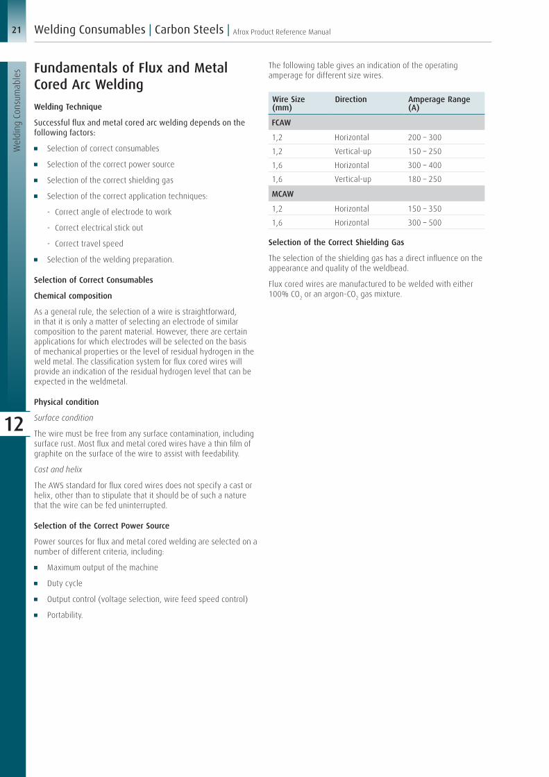
Fundamentals of Flux and Metal Cored Arc WeldingWelding Technique
Successful flux and metal cored arc welding depends on the following factors:
Selection of correct consumables
Selection of the correct power source
Selection of the correct shielding gas
Selection of the correct application techniques:
- Correct angle of electrode to work
- Correct electrical stick out
- Correct travel speed
Selection of the welding preparation.
Selection of Correct Consumables
Chemical composition
As a general rule, the selection of a wire is straightforward, in that it is only a matter of selecting an electrode of similar composition to the parent material. However, there are certain applications for which electrodes will be selected on the basis of mechanical properties or the level of residual hydrogen in the weld metal. The classification system for flux cored wires will provide an indication of the residual hydrogen level that can be expected in the weldmetal.
Physical condition
Surface condition
The wire must be free from any surface contamination, including surface rust. Most flux and metal cored wires have a thin film of graphite on the surface of the wire to assist with feedability.
Cast and helix
The AWS standard for flux cored wires does not specify a cast or helix, other than to stipulate that it should be of such a nature that the wire can be fed uninterrupted.
Selection of the Correct Power Source
Power sources for flux and metal cored welding are selected on a number of different criteria, including:
Maximum output of the machine
Duty cycle
Output control (voltage selection, wire feed speed control)
Portability.
The following table gives an indication of the operating amperage for different size wires.
Wire Size (mm)
Direction Amperage Range (A)
FCAW
1,2 Horizontal 200 – 300
1,2 Vertical-up 150 – 250
1,6 Horizontal 300 – 400
1,6 Vertical-up 180 – 250
MCAW
1,2 Horizontal 150 – 350
1,6 Horizontal 300 – 500
Selection of the Correct Shielding Gas
The selection of the shielding gas has a direct influence on the appearance and quality of the weldbead.
Flux cored wires are manufactured to be welded with either 100% CO2 or an argon-CO2 gas mixture.

22Afrox Product Reference Manual
Wel
ding
Con
sum
able
s
| Welding Consumables | Carbon Steels
12
Undercutting and burnback
No working condition
Plate thickness (mm) positional welding
Plate thickness (mm) flat and horizontal
0
0 5 10 15 20
10 20
Burnback and arc instability
Flat and horizontaloptimum parameters
Positional weldingoptimum parameters
Defect-free zone
Defect zoneElectrode stubbing and spatter
Current (A)
Current/Voltage Envelope for Argoshield 52Vo
ltage
(V)
40
30
25
20
15
35
1050 400100 150 200 450250 300 350
1,6 mm1,2 mm
Correct Application Techniques
Direction of travel
Flux cored welding is normally performed using a ‘drag’ technique. The welding gun is tilted to a 50–60° backhand angle. If, however, a flatter bead profile is required, the backhand angle can be reduced.
Metal cored wire, because of its similarity to solid wires (no slag formers added to the core mainly metallic powders), are normally welded with the ‘push’ technique.
Travel direction (Flux cored)
Travel direction (Metal cored)
When welding butt welds with flux or metal cored wires, the torch should be positioned within the centre of the groove and tilted at an angle of ±20°. Flux cored welding is still performed with the ‘drag’ technique and metal cored welding with the ‘push’ technique.
Torch position for butt welds
Torch angle for fillet welds
When welding horizontal-vertical fillet welds, the wire tip must be aimed exactly in the corner of the joint. For the first bead, the welding gun is tilted at an angle of 30–40° from the horizontal plane. Flux cored welding is still performed with the ‘drag’ technique and metal cored welding with the ‘push’ technique.
50–60°
5mm
2–3mm
10°
0–15°
90°90°

23 Afrox Product Reference Manual
Wel
ding
Con
sum
able
s
Welding Consumables | Carbon Steels |
12
Vertical-up
Vertical-up welding can be undertaken in a similar way, as MMA with a slight weave motion. Vertical-up welding with metal cored wire can successfully be undertaken with pulsed MIG welding equipment.
Electrical stick out
1 Gas nozzle
2 Contact tube setback
3 Consumable electrode
4 Workpiece5 Standoff distance6 Contact tube7 Visible stick out8 Arc length9 Electrical stick out
1
2
35
6
7
8
9
4
The electrical stick out is the distance between the end of the contact tip and the end of the wire. An increase in the electrical stick out results in an increase in the electrical resistance. The resultant increase in temperature has a positive influence in the melt-off rate of the wire that will have an influence on the weldbead profile.
Travel speed
The construction of flux and metal cored wires ensures the highest current density for a given current setting compared to all other welding processes.
High current densities produce high deposition rates.
Current Density=
Amperage
Cross-sectional area of wire
or J=
I
A
Electrode / Wire
Diameter (mm)
Cross Section Area (mm2)
Current (A)
Current Density (A/mm2)
Deposition Rate (kg/h)
MMA electrode (E7024)
4,0 12,57 235 18,7 3,0
FCAW wire (E71T-1)
1,2 0,625 235 376,0 3,8
MIG wire (ER70S-6)
1,2 1,130 235 287,5 3,3
MCAW wire (E70C-6M)
1,2 0,625 300 480,0 5,2
Consequently, travel speed must be increased proportionately to maintain control of the weld pool and bead shape, and to balance the deposited weld metal versus fusion obtained.
Travel speed too slow
Excessive penetrationExcessive weld metal depositedRoll over of weld metal on horizontal plate
Correct travel speed
Recommended penetration depthProper sidewall fusion without roll over or undercut
Travel speed too fast
Weld bead too smallInadequate sidewall fusionLack of root penetration
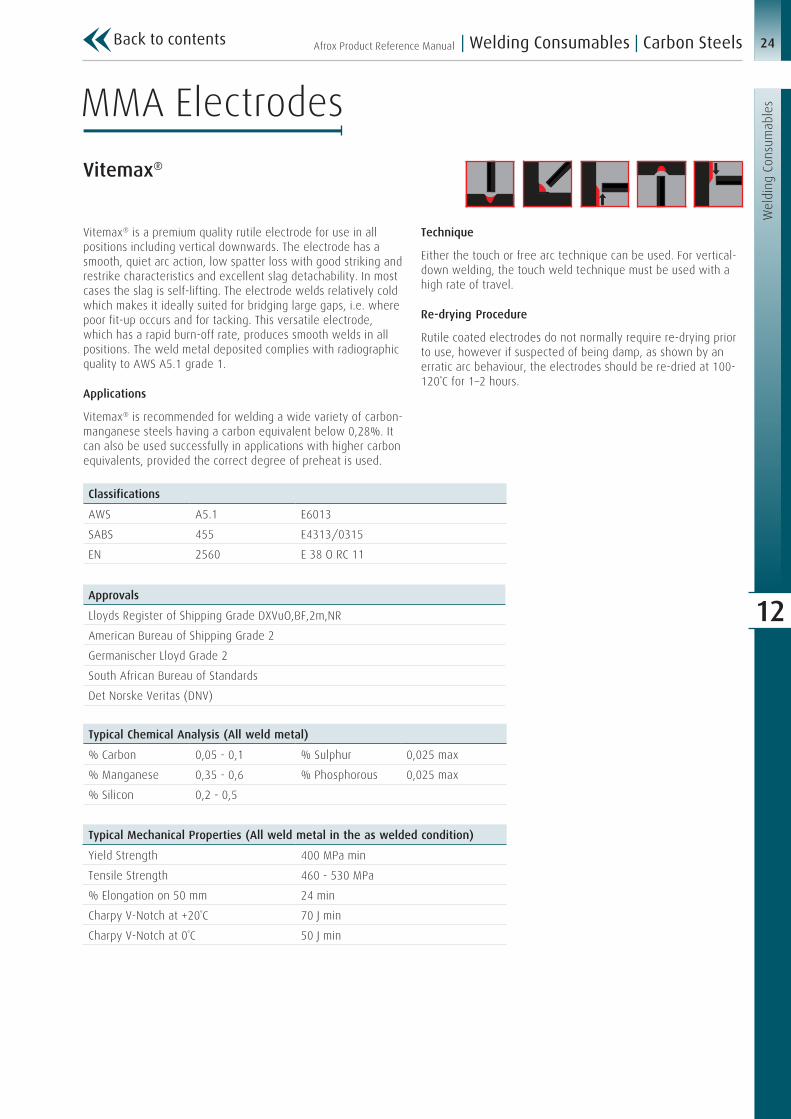
24Afrox Product Reference Manual
Wel
ding
Con
sum
able
s
| Welding Consumables | Carbon Steels
12
Vitemax®
Vitemax® is a premium quality rutile electrode for use in all positions including vertical downwards. The electrode has a smooth, quiet arc action, low spatter loss with good striking and restrike characteristics and excellent slag detachability. In most cases the slag is self-lifting. The electrode welds relatively cold which makes it ideally suited for bridging large gaps, i.e. where poor fit-up occurs and for tacking. This versatile electrode, which has a rapid burn-off rate, produces smooth welds in all positions. The weld metal deposited complies with radiographic quality to AWS A5.1 grade 1.
Applications
Vitemax® is recommended for welding a wide variety of carbon- manganese steels having a carbon equivalent below 0,28%. It can also be used successfully in applications with higher carbon equivalents, provided the correct degree of preheat is used.
Technique
Either the touch or free arc technique can be used. For vertical-down welding, the touch weld technique must be used with a high rate of travel.
Re-drying Procedure
Rutile coated electrodes do not normally require re-drying prior to use, however if suspected of being damp, as shown by an erratic arc behaviour, the electrodes should be re-dried at 100-120˚C for 1–2 hours.
Classifications
AWS A5.1 E6013
SABS 455 E4313/0315
EN 2560 E 38 O RC 11
Approvals
Lloyds Register of Shipping Grade DXVuO,BF,2m,NR
American Bureau of Shipping Grade 2
Germanischer Lloyd Grade 2
South African Bureau of Standards
Det Norske Veritas (DNV)
Typical Mechanical Properties (All weld metal in the as welded condition)
Yield Strength 400 MPa min
Tensile Strength 460 - 530 MPa
% Elongation on 50 mm 24 min
Charpy V-Notch at +20˚C 70 J min
Charpy V-Notch at 0˚C 50 J min
Typical Chemical Analysis (All weld metal)
% Carbon 0,05 - 0,1 % Sulphur 0,025 max
% Manganese 0,35 - 0,6 % Phosphorous 0,025 max
% Silicon 0,2 - 0,5
MMA Electrodes
Back to contents
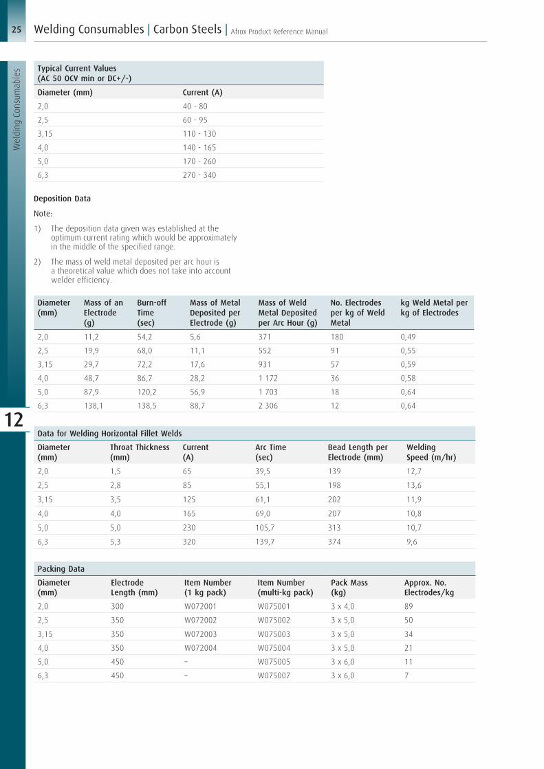
25 Afrox Product Reference Manual
Wel
ding
Con
sum
able
s
Welding Consumables | Carbon Steels |
12
Packing Data
Diameter (mm)
Electrode Length (mm)
Item Number (1 kg pack)
Item Number (multi-kg pack)
Pack Mass (kg)
Approx. No. Electrodes/kg
2,0 300 W072001 W075001 3 x 4,0 89
2,5 350 W072002 W075002 3 x 5,0 50
3,15 350 W072003 W075003 3 x 5,0 34
4,0 350 W072004 W075004 3 x 5,0 21
5,0 450 – W075005 3 x 6,0 11
6,3 450 – W075007 3 x 6,0 7
Data for Welding Horizontal Fillet Welds
Diameter (mm)
Throat Thickness (mm)
Current (A)
Arc Time (sec)
Bead Length per Electrode (mm)
Welding Speed (m/hr)
2,0 1,5 65 39,5 139 12,7
2,5 2,8 85 55,1 198 13,6
3,15 3,5 125 61,1 202 11,9
4,0 4,0 165 69,0 207 10,8
5,0 5,0 230 105,7 313 10,7
6,3 5,3 320 139,7 374 9,6
Diameter (mm)
Mass of an Electrode (g)
Burn-off Time (sec)
Mass of Metal Deposited per Electrode (g)
Mass of Weld Metal Deposited per Arc Hour (g)
No. Electrodes per kg of Weld Metal
kg Weld Metal per kg of Electrodes
2,0 11,2 54,2 5,6 371 180 0,49
2,5 19,9 68,0 11,1 552 91 0,55
3,15 29,7 72,2 17,6 931 57 0,59
4,0 48,7 86,7 28,2 1 172 36 0,58
5,0 87,9 120,2 56,9 1 703 18 0,64
6,3 138,1 138,5 88,7 2 306 12 0,64
Typical Current Values(AC 50 OCV min or DC+/-)
Diameter (mm) Current (A)
2,0 40 - 80
2,5 60 - 95
3,15 110 - 130
4,0 140 - 165
5,0 170 - 260
6,3 270 - 340
Deposition Data
Note:
1) The deposition data given was established at the optimum current rating which would be approximately in the middle of the specified range.
2) The mass of weld metal deposited per arc hour is a theoretical value which does not take into account welder efficiency.

26Afrox Product Reference Manual
Wel
ding
Con
sum
able
s
| Welding Consumables | Carbon Steels
12
Speedcraft is a standard grade general-purpose rutile type electrode, suitable for welding mild steel in all positions using AC or DC power sources. It has a coating composition that promotes a smooth arc action, low spatter loss and easily removable slag. Good strike and restrike characteristics at 50 OCV make it suitable for use on home welders and industrial equipment. It has a rapid burn-off rate and deposits a smooth convex weld bead with fine ripples.
Applications
Speedcraft is recommended for welding a wide variety of carbon-manganese steels and commercial mild steels having a tensile strength up to approximately 530 MPa.
Technique
Either the touch or free arc technique can be used when welding with Speedcraft.
Re-drying Procedure
Rutile coated electrodes do not normally require re-drying prior to use, however, if suspected of being damp as shown by an erratic arc behaviour, the electrodes should be re-dried at 100-120˚C for 1-2 hours.
Classifications
AWS A5.1 E6013
SABS 455 E4313/0315
EN ISO 2560 E 38 O RC 11
Approvals
South African Bureau of Standards
Lloyds Register of Shipping Grade DXVuO,BF,1m,No
Typical Mechanical Properties (All weld metal in the as welded condition)
Yield Strength 400 MPa min
Tensile Strength 460 - 530 MPa
% Elongation on 50 mm 22 min
Charpy V-Notch at +20˚C 70 J min
Charpy V-Notch at 0˚C 50 J min
Typical Chemical Analysis (All weld metal)
% Carbon 0,05 - 0,1 % Sulphur 0,025 max
% Manganese 0,35 - 0,6 % Phosphorous 0,025 max
% Silicon 0,2 - 0,5
Typical Current Values(AC 50 OCV min or DC+/-)
Diameter (mm) Current (A)
2,5 60 - 85
3,15 110 - 130
4,0 140 - 165
Superweld Speedcraft

27 Afrox Product Reference Manual
Wel
ding
Con
sum
able
s
Welding Consumables | Carbon Steels |
12
Diameter (mm)
Mass of an Electrode (g)
Burn-off Time (sec)
Mass of Metal Deposited per Electrode (g)
Mass of Weld Metal Deposited per Arc Hour (g)
No. Electrodes per kg of Weld Metal
kg Weld Metal per kg of Electrodes
2,5 20,0 58,8 10,1 600 98 0,51
3,15 29,3 63,8 16,7 900 59 0,57
4,0 45,9 76,4 26,1 1 600 38 0,57
Packing Data
Diameter (mm)
Electrode Length (mm)
Item Number (1 kg pack)
Item Number (multi-kg pack)
Pack Mass (kg)
Approx. No. Electrodes/kg
2,5 350 W072122 W075122 3 x 5,0 50
3,15 350 W072123 W075123 3 x 5,0 34
4,0 350 W072124 W075124 3 x 5,0 22
Data for Welding Horizontal Fillet Welds
Diameter (mm)
Throat Thickness (mm)
Current (A)
Arc Time (sec)
Bead Length per Electrode (mm)
Welding Speed (m/h)
2,5 2,2 80 52,5 180 12,3
3,15 2,8 120 57,7 197 12,3
4,0 3,5 160 74,6 208 10,0
Deposition Data
Note:
1) The deposition data given was established at the optimum current rating which would be approximately in the middle of the specified range.
2) The mass of weld metal deposited per arc hour is a theoretical value which does not take into account welder efficiency.

28Afrox Product Reference Manual
Wel
ding
Con
sum
able
s
| Welding Consumables | Carbon Steels
12
Packing Data
Diameter (mm)
Electrode Length (mm)
Item Number (1 kg pack)
Item Number (multi-kg pack)
Pack Mass (kg)
2,5 350 W072132 W075132 5,0
3,15 350 W072133 W075133 5,0
4,0 350 W072134 W075134 5,0
Transarc® 6013 is a newly developed electrode from Afrox, produced locally at the world class manufacturing facility in Brits. The Brits consumables factory adopts the best manufacturing practices and standards and undergoes regular audits from approval bodies such as TÜV and SABS, ensuring that quality is not compromised and the highest standards are maintained on all the products.
Transarc® 6013 is a rutile electrode of a very good quality for welding mild steels. Transarc® 6013 has been developed and produced with a brand new formulation after extensive research.
Applications
Suitable electrode for mild steel welding, fillet, tack and butt welding, and for bridging large joint gaps and welding that requires a smooth and clean bead appearance.
Classifications
AWS A5.1 E6013
SANS 2560 E 350 RC 11
EN ISO 2560 E 350 RC 11
Transarc® 6013
Typical Mechanical Properties (All weld metal in the as welded condition)
Yield Strength 507 MPa min
Tensile Strength 546 MPa
% Elongation on 50 mm 23 min
Typical Chemical Analysis (All weld metal)
% Carbon 0,04 - 0,055 % Molybdenum 0,002
% Manganese 0,5 - 0,6 % Nickel 0,001
% Silicon 0,2 - 0,35 % Vanadium 0,018
Typical Current Values(AC 50 OCV min or DC+/-)
Diameter (mm) Current (A)
2,5 60 - 95
3,15 110 - 130
4,0 140 - 165
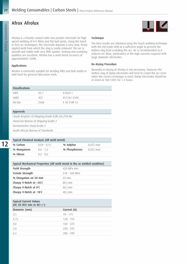
29 Afrox Product Reference Manual
Wel
ding
Con
sum
able
s
Welding Consumables | Carbon Steels |
12
Afrox Afrolux
Afrolux is a heavily coated rutile iron powder electrode for high speed welding of H-V fillets and flat butt joints. Using the touch or free arc techniques, the electrode deposits a very neat, finely rippled weld from which the slag is easily removed. The arc is smooth and stable with very little spatter. Striking and restriking qualities are excellent. Afrolux has a weld metal recovery of approximately 160%.
Applications
Afrolux is eminently suitable for welding fillet and butt welds in mild steel for general fabrication work.
Technique
The best results are obtained using the touch welding technique with the electrode held at a sufficient angle to prevent the molten slag from crowding the arc. AC is recommended as it reduces arc blow, particularly at the high currents required with large diameter electrodes.
Re-drying Procedure
Normally re-drying of Afrolux is not necessary, however the molten slag of damp electrodes will tend to crowd the arc even when the correct technique is used. Damp electrodes should be re-dried at 100-120˚C for 1-2 hours.
Classifications
AWS A5.1 E7024-1
SABS 455 E5124/-2345
EN ISO 2560 E 42 0 RR 13
Approvals
Lloyds Register of Shipping Grade D,BF,2m,2Ym,No
American Bureau of Shipping Grade 2
Germanischer Lloyd Grade 2
South African Bureau of Standards
Typical Mechanical Properties (All weld metal in the as welded condition)
Yield Strength 420 MPa min
Tensile Strength 510 - 560 MPa
% Elongation on 50 mm 22 min
Charpy V-Notch at +20˚C 80 J min
Charpy V-Notch at 0˚C 60 J min
Charpy V-Notch at -18˚C 40 J min
Typical Chemical Analysis (All weld metal)
% Carbon 0,04 - 0,12 % Sulphur 0,025 max
% Manganese 0,6 - 1,2 % Phosphorous 0,025 max
% Silicon 0,2 - 0,6
Typical Current Values(AC 50 OCV min or DC+/-)
Diameter (mm) Current (A)
2,5 70 - 115
3,15 120 - 155
4,0 160 - 225
5,0 220 - 335
6,3 280 - 390

30Afrox Product Reference Manual
Wel
ding
Con
sum
able
s
| Welding Consumables | Carbon Steels
12
Diameter (mm)
Mass of an Electrode (g)
Burn-off Time (sec)
Mass of Metal Deposited per Electrode (g)
Mass of Weld Metal Deposited per Arc Hour (g)
No. Electrodes per kg of Weld Metal
kg Weld Metal per kg of Electrodes
2,5 30,3 63,2 32,7 1 139 48 0,61
3,15 66,9 77,0 54,1 1 944 25 0,61
4,0 102,4 84,9 108,4 2 755 16 0,62
5,0 157,7 91,0 164,3 3 694 8 0,63
6,3 248,0 125,5 250,9 4 735 7 0,66
Packing Data
Diameter (mm)
Electrode Length (mm)
Approx. No. Electrodes/kg
Pack Mass (kg)
Item Number (multi-kg pack)
2,5 350 30,0 3 x 4,0 W075202
3,15 450 16,0 3 x 5,0 W075203
4,0 450 11,0 3 x 5,0 W075204
5,0 450 7,0 3 x 5,0 W075205
6,3 450 4,0 3 x 5,0 W075207
Data for Welding Horizontal Fillet Welds
Diameter (mm)
Throat Thickness (mm)
Current (A)
Arc Time (sec)
Bead Length per Electrode (mm)
Welding Speed (m/h)
2,5 2,9 90 64,8 240 13,3
3,15 3,1 135 88,2 360 14,7
4,0 3,8 200 93,6 432 16,6
5,0 4,1 275 102,0 528 18,6
6,3 5,0 350 132,0 590 16,1
Deposition Data
Note:
1) The deposition data given was established at the optimum current rating which would be approximately in the middle of the specified range.
2) The mass of weld metal deposited per arc hour is a theoretical value which does not take into account welder efficiency.

31 Afrox Product Reference Manual
Wel
ding
Con
sum
able
s
Welding Consumables | Carbon Steels |
12
Afrox 7018-1
Afrox 7018-1 is an AC/DC all-position basic coated hydrogen-controlled electrode of premium quality. It was designed for applications where fracture toughness and the most severe X-ray requirements in all positions are required. This electrode combines outstanding all-positional welding characteristics, excellent bead profile and appearance in both root and capping passes with a smooth stable arc and quick freezing weld metal. Its ability to operate at lower than normal currents and give a fully penetrating weld bead is of particular significance for root runs which are inaccessible for back gouging. These properties give the electrode outstanding welder appeal.
Applications
Afrox 7018-1 is used for the welding of a variety of carbon- manganese and low alloy steels used in the fabrication of pressure vessels, pipe work and in general structural fabrication work. It is recommended for applications where severe X-ray requirements and mechanical properties have to be met.
Technique
As with all basic hydrogen-controlled electrodes, as short an arc as possible should be kept at all times. When starting with a new electrode, the arc should be initiated a short distance ahead of the start or crater and worked back over this distance before continuing the weld in the required direction. On larger
size joints, several stringer beads should be used where possible in preference to one large weaved bead to ensure optimum mechanical properties. DC- should be used for root passes where poor fit-up is a factor to be taken into account.
Re-drying Procedure
Hydrogen-controlled electrodes must be re-baked prior to use, the baking temperature required being governed by the maximum hydrogen content tolerable in the deposited weld metal. For a maximum of 5-10 ml H2/100 g, re-bake at a temperature of 350-370˚C for 1-2 hours. (Please consult the section regarding the storage, handling and treatment of low hydrogen electrodes).
Afrox 7018-1 is manufactured and tested in accordance with the requirements of AWS A5.01. Different class and schedules can be provided upon request.
Classifications
AWS A5.1 E7018-1 H8
SABS 455 E5118/-4427H
EN 2560 E 42 4 B 32 H5
Approvals
Lloyds Register of Shipping Grade DXVuO,BF,3m,3Ym,H15
American Bureau of Shipping Grade 3Y,3H
Germanischer Lloyd Grade 3YH10
TÜV
South African Bureau of Standards
Typical Mechanical Properties (All weld metal)
As Welded Stress Relieved (630˚C for 8 hours)
0,2% Proof Stress 420 MPa min 0,2% Proof Stress 350 MPa min
Tensile Strength 510 - 570 MPa Tensile Strength 485 MPa min
% Elongation on 50 mm 26 min % Elongation on 50 mm 22 min
Charpy V-Notch at -29˚C 130 J min Charpy V-Notch at -29˚C 80 J min
Charpy V-Notch at -46˚C 80 J min
Typical Chemical Analysis (All weld metal)
% Carbon 0,05 - 0,09 % Sulphur 0,025 max
% Manganese 1,3 - 1,5 % Phosphorous 0,025 max
% Silicon 0,25 - 0,45

32Afrox Product Reference Manual
Wel
ding
Con
sum
able
s
| Welding Consumables | Carbon Steels
12
Typical Current Values (DC+/- for root welds or AC 70 OCV min)
Diameter (mm) Downhand Vertical-up Overhead
2,5 70 - 100 75 - 85 80 - 90
3,15 90 - 135 95 - 110 100 - 110
4,0 135 - 200 140 - 155 145 - 155
5,0 180 - 260 – –
6,3 245 - 380 – –
Diameter (mm)
Mass of an Electrode (g)
Burn-off Time (sec)
Mass of Metal Deposited per Electrode (g)
Mass of Weld Metal Deposited per Arc Hour (g)
No. Electrodes per kg of Weld Metal
kg Weld Metal per kg of Electrodes
2,5 21,6 64,2 13,6 761 74 0,62
3,15 33,4 70,0 21,3 1 094 47 0,63
4,0 52,0 71,9 34,0 1 700 30 0,65
5,0 100,3 100,3 67,7 2 428 15 0,67
6,3 150,6 110,5 104,2 3 394 10 0,69
Data for Welding Horizontal Fillet Welds
Diameter (mm)
Throat Thickness (mm)
Current (A)
Arc Time (sec)
Bead Length per Electrode (mm)
Welding Speed (m/h)
2,5 3,0 85 62,0 165 9,6
3,15 4,2 125 73,0 215 10,6
4,0 5,0 175 80,0 225 10,1
5,0 6,0 225 106,2 287 9,7
6,3 6,9 320 103,2 349 12,2
Packing Data
Diameter (mm)
Electrode Length (mm)
Approx. No. Electrodes/kg
Pack mass (kg)
Item Number(multi-kg pack)
2,5 350 46 3 x 4,0 W075282
3,15 350 30 3 x 4,0 W075283
4,0 350 19 3 x 4,0 W075284
5,0 450 10 3 x 6,0 W075285
6,3 450 7 3 x 6,0 W075287
7018-1 DriPac (2 kg)
Diameter (mm)
Electrode Length (mm)
Downhand Vertical-up Overhead Item Number
2,5 350 70 - 100 75 - 85 80 - 90 W075482
3,15 350 90 - 135 95 - 110 100 - 110 W075483
4,0 350 135 - 200 140 - 155 145 - 155 W075484
5,0 450 180 - 260 - - W075485
6,3 450 245 - 380 - - W075487
Deposition Data
Note:
1) The deposition data given was established at the optimum current rating which would be approximately in the middle of the specified range.
2) The mass of weld metal deposited per arc hour is a theoretical value which does not take into account welder efficiency.

33 Afrox Product Reference Manual
Wel
ding
Con
sum
able
s
Welding Consumables | Carbon Steels |
12
Afrox 78MR
Specially formulated with a unique moisture resistant coating, 78MR is designed to reduce hydrogen at its primary source – moisture in the electrode coating. This means 78MR starts with a low initial moisture content and moisture regain, after extended exposure to the atmosphere, and is extremely low when compared with conventional hydrogen-controlled electrodes. Afrox 78MR is an AC/DC all-position basic coated hydrogen-controlled electrode which features excellent mechanical properties and low moisture regain rates after baking. The low moisture content of the coating and the high resistance to moisture re-absorption is a major benefit long recognised by manufacturers of critical components where avoidance of hydrogen induced cracking is of crucial importance. Afrox 78MR exhibits outstanding all positional welding characteristics with excellent bead profile and appearance. The arc is smooth and stable, giving a fully penetrating weld bead. The slag release in all positions is excellent and the electrode operates with minimal spatter on both AC and DC. Afrox 78MR is recommended for all structural applications where stringent mechanical properties and X-ray quality joints in all positions are required.
Applications
Afrox 78MR is recommended for welding a wide range of carbon-manganese and low alloy steels used in structural applications and for the construction of pressure vessels.
Technique
As with all hydrogen-controlled electrodes, as short an arc as possible should be kept at all times. When starting with a new electrode, the arc should be initiated a short distance ahead of the start of the weld or crater and worked back over this distance before continuing the weld in the required direction. On heavier sections, several stringer beads should be used in preference to one large weave bead to ensure optimum mechanical properties.
Re-drying Procedure
Hydrogen-controlled electrodes must be re-baked prior to use, the baking temperature required being governed by the maximum hydrogen content tolerable in the deposited weld metal. For 5-10 ml H2/100 g, re-bake at a temperature of 250-270˚C for 1-2 hours, and for <5 ml H2/100 g, a temperature of 370-400˚C for 1-2 hours. (Please consult the section regarding the storage, handling and treatment of low hydrogen electrodes).
Afrox 78MR is manufactured and tested in accordance with the requirements of AWS A5.1.
Classifications
AWS A5.1 E7018-1 H4 R
SABS 455 E5118/-4427H
SANS 2560 E 424 B 12 H10
EN ISO 2560 AE 424 B 12 H10
Typical Chemical Analysis (All weld metal)
% Carbon 0,05 - 0,09 % Sulphur 0,025 max
% Manganese 1,25 - 1,5 % Phosphorous 0,025 max
% Silicon 0,25 - 0,45
Typical Mechanical Properties (All weld metal)
Yield Strength 420 MPa min
Tensile Strength 510 - 650 MPa
% Elongation on 50 mm 26 min
Charpy V-Notch at -20˚C 120 J min
Charpy V-Notch at -29˚C 100 J min
Charpy V-Notch at -40˚C 80 J min
Approvals
Lloyds Register of Shipping Grade DXVuO,BF,3m,3Ym,H15
American Bureau of Shipping Grade 3Y,3H
Germanischer Lloyd Grade 3YH10
South African Bureau of Standards

34Afrox Product Reference Manual
Wel
ding
Con
sum
able
s
| Welding Consumables | Carbon Steels
12Packing Data
Diameter (mm)
Electrode Length (mm)
Item Number (1 kg pack)
Approx. No. Electrodes/kg
Pack mass (kg)
Item Number (multi-kg pack)
2,5 350 W072272 45 3 x 4,0 W075272
3,15 350 W072273 29 3 x 4,0 W075273
4,0 350 - 18 3 x 4,0 W075274
5,0 450 - 9 3 x 6,0 W075275
6,3 450 - 6 3 x 6,0 W075277
Typical Current Values (DC+/- or AC 70 OCV min)
Diameter (mm) Current (A)
2,5 70 - 100
3,15 100 - 150
4,0 140 - 200
5,0 160 - 285
6,3 250 - 390
Diameter (mm)
Mass of an Electrode (g)
Burn-off Time (sec)
Mass of Metal Deposited per Electrode (g)
Mass of Weld Metal Deposited per Arc Hour (g)
No. Electrodes per kg of Weld Metal
kg Weld Metal per kg of Electrodes
2,5 22,2 66,5 13,7 742 73 0,61
3,15 34,3 71,3 21,5 1 084 47 0,62
4,0 54,6 78,5 34,5 1 582 29 0,63
5,0 108,5 114,3 72,0 2 270 14 0,66
6,3 155,5 116,0 106,9 3 312 10 0,68
Deposition Data
Note:
1) The deposition data given was established at the optimum current rating which would be approximately in the middle of the specified range.
2) The mass of weld metal deposited per arc hour is a theoretical value which does not take into account welder efficiency.
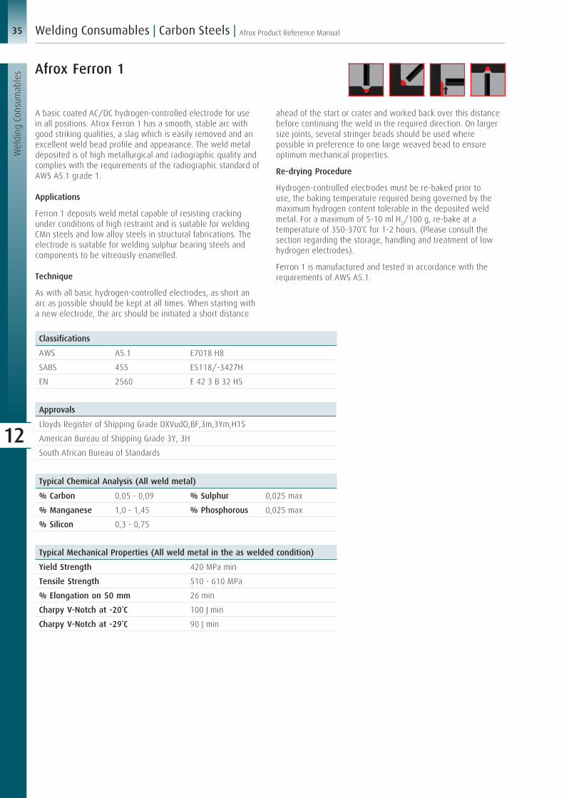
35 Afrox Product Reference Manual
Wel
ding
Con
sum
able
s
Welding Consumables | Carbon Steels |
12
Afrox Ferron 1
A basic coated AC/DC hydrogen-controlled electrode for use in all positions. Afrox Ferron 1 has a smooth, stable arc with good striking qualities, a slag which is easily removed and an excellent weld bead profile and appearance. The weld metal deposited is of high metallurgical and radiographic quality and complies with the requirements of the radiographic standard of AWS A5.1 grade 1.
Applications
Ferron 1 deposits weld metal capable of resisting cracking under conditions of high restraint and is suitable for welding CMn steels and low alloy steels in structural fabrications. The electrode is suitable for welding sulphur bearing steels and components to be vitreously enamelled.
Technique
As with all basic hydrogen-controlled electrodes, as short an arc as possible should be kept at all times. When starting with a new electrode, the arc should be initiated a short distance
ahead of the start or crater and worked back over this distance before continuing the weld in the required direction. On larger size joints, several stringer beads should be used where possible in preference to one large weaved bead to ensure optimum mechanical properties.
Re-drying Procedure
Hydrogen-controlled electrodes must be re-baked prior to use, the baking temperature required being governed by the maximum hydrogen content tolerable in the deposited weld metal. For a maximum of 5-10 ml H2/100 g, re-bake at a temperature of 350-370˚C for 1-2 hours. (Please consult the section regarding the storage, handling and treatment of low hydrogen electrodes).
Ferron 1 is manufactured and tested in accordance with the requirements of AWS A5.1.
Classifications
AWS A5.1 E7018 H8
SABS 455 E5118/-3427H
EN 2560 E 42 3 B 32 H5
Approvals
Lloyds Register of Shipping Grade DXVudO,BF,3m,3Ym,H15
American Bureau of Shipping Grade 3Y, 3H
South African Bureau of Standards
Typical Chemical Analysis (All weld metal)
% Carbon 0,05 - 0,09 % Sulphur 0,025 max
% Manganese 1,0 - 1,45 % Phosphorous 0,025 max
% Silicon 0,3 - 0,75
Typical Mechanical Properties (All weld metal in the as welded condition)
Yield Strength 420 MPa min
Tensile Strength 510 - 610 MPa
% Elongation on 50 mm 26 min
Charpy V-Notch at -20˚C 100 J min
Charpy V-Notch at -29˚C 90 J min

36Afrox Product Reference Manual
Wel
ding
Con
sum
able
s
| Welding Consumables | Carbon Steels
12
Diameter (mm)
Mass of an Electrode (g)
Burn-off Time (sec)
Mass of Metal Deposited per Electrode (g)
Mass of Weld Metal Deposited per Arc Hour (g)
No. Electrodes per kg of Weld Metal
kg Weld Metal per kg of Electrodes
2,5 22,4 70,3 14,0 716 72 0,62
3,15 35,6 79,9 22,3 1 002 45 0,62
4,0 50,6 71,1 33,3 1 686 31 0,65
5,0 99,8 101,5 69,0 2 447 15 0,69
6,3 157,6 116,9 108,8 3 351 10 0,69
Typical Current Values (DC+/- or AC 70 OCV min)
Diameter (mm) Current (A)
2,5 70 - 100
3,15 100 - 140
4,0 145 - 180
5,0 190 - 280
6,3 260 - 370
Data for Welding Horizontal Fillet Welds
Diameter (mm)
Throat Thickness (mm)
Current (A)
Arc Time (sec)
Bead Length per Electrode (mm)
Welding Speed (m/h)
2,5 2,5 85 64,2 146 8,2
3,15 3,1 125 75,0 186 8,9
4,0 5,0 175 69,6 204 10,6
5,0 5,9 225 96,6 258 9,6
6,3 6,0 320 99,0 368 13,4
Packing Data
Diameter (mm)
Electrode Length (mm)
Approx. No. Electrodes/kg
Pack mass (kg)
Item Number (multi-kg pack)
2,5 350 45 3 x 4,0 W075312
3,15 350 28 3 x 4,0 W075313
4,0 350 20 3 x 4,0 W075314
5,0 450 10 3 x 6,0 W075315
6,3 450 6 3 x 6,0 W075317
Deposition Data
Note:
1) The deposition data given was established at the optimum current rating which would be approximately in the middle of the specified range.
2) The mass of weld metal deposited per arc hour is a theoretical value which does not take into account welder efficiency.

37 Afrox Product Reference Manual
Wel
ding
Con
sum
able
s
Welding Consumables | Carbon Steels |
12
Heavy coated rutile high-efficiency electrodes with 160% metal recovery. Suitable for container and storage vessel construction, filler and capping runs of multi-layer weldments. Good notch toughness, automatic striking and re-striking, bead can be drawn out. Excellent deslagging characteristics.
Re-drying Procedure
Provided that electrodes are stored in dry conditions, re-drying is not necessary.
Classifications
Standards
AWS/ASME SF A 5.1 E7024
EN 2560 E 38 O RR 73
Electrode Marking
OER 7024
Typical Chemical Analysis (All weld metal)
% Carbon 0,06 % Sulphur 0,03 max
% Manganese 0,7 % Phosphorous 0,03 max
% Silicon 0,35
Approvals
Lloyds Register of Shipping Grade D,BF,1m,NR
Packing Data
Diameter (mm)
Current (A)
Electrode Length (mm)
Pack Mass (kg)
Pieces per Carton (approx.)
Item Number
2,5 90 - 120 350 5,0 155 W111042
3,15 130 - 160 450 5,0 73 W111043
4,0 180 - 220 450 5,0 46 W111044
5,0 270 - 320 450 5,0 30 W111045
6,3 300 - 360 450 5,0 20 W111046
Oerlikon Ferromatic

38Afrox Product Reference Manual
Wel
ding
Con
sum
able
s
| Welding Consumables | Carbon Steels
12
Tenacito 7018-1 is a low hydrogen, basic covered electrode for welding medium tensile strength structural and fine grained steels. It has excellent positional weldability and stable arc characteristics.
Re-drying Procedure
Use dry electrodes only. Re-drying should be carried out at 300-350ºC for 2 hours.
Classifications
Standards
AWS A 5.1 7018-1
EN 2560 E 42 6B 42 H5
Electrode Marking
Tenacito 7018-1
Approvals
Lloyds Register of Shipping Grade DXVuO,BF,3m,3Ym,H15
Typical Chemical Analysis (All weld metal)
% Carbon 0,07 % Sulphur <0,02
% Manganese 1,2 % Phosphorous <0,02
% Silicon 0,4
Typical Mechanical Properties (All weld metal in the as welded condition)
Yield Strength >440 MPa
Tensile Strength 520 - 620 MPa
% Elongation on 5d >25
Impact Strength at +20ºC >160 J
Impact Strength at 0ºC >150 J
Impact Strength at -20ºC >130 J
Impact Strength at -40ºC >100 J
Impact Strength at -60ºC >50 J
Oerlikon Tenacito
Packing Data
Diameter (mm)
Current (A)
Electrode Length (mm)
Pack Mass (kg)
Item Number (Tenacito C5)
Item Number (Tenacito)
2,5 65 - 95 350 5,0 W111472 W075372
3,15 90 - 140 350 5,0 W111473 W075373
4,0 140 - 185 450 5,0 W111474 W075374
5,0 185 - 240 450 5,0 W111475 W075375
6,3 240 - 340 450 5,0 - W111066

39 Afrox Product Reference Manual
Wel
ding
Con
sum
able
s
Welding Consumables | Carbon Steels |
12
Medium coated, rutile type electrode especially suitable for light gauge sheet welding. When fillet welding, the Fincord M electrode can be kept in contact with the workpiece with no resultant excess convexity. Very little spatter loss. Smooth bead appearance.
Re-drying Procedure
Provided that electrodes are stored in dry conditions, re-drying is not necessary.
Classifications
Standards
AWS/ASME SF A 5.1 E6013
EN 2560 E35 A R 11
Electrode Marking
OER 6013
Typical Chemical Analysis (All weld metal)
% Carbon 0,05 % Sulphur 0,02 max
% Manganese 0,5 % Phosphorous 0,02 max
% Silicon 0,45
Packing Data
Diameter (mm)
Current (A)
Electrode Length (mm)
Pack Mass (kg)
Pieces per Carton (approx.)
Item Number
2,5 60 - 90 350 5,0 250 W111002
3,15 90 - 140 350 5,0 170 W111003
4,0 120 - 190 350 5,0 106 W111004
5,0 160 - 240 450 5,0 69 W111005
6,3 200 - 290 450 5,0 32 W111006
Typical Mechanical Properties (All weld metal in the as welded condition)
0,2% Proof Stress >360 MPa
Tensile Strength 450 - 560 MPa
% Elongation on 5d >22
Impact Strength at +20ºC >60 J
Impact Strength at 0ºC >40 J
Oerlikon Fincord M

40Afrox Product Reference Manual
Wel
ding
Con
sum
able
s
| Welding Consumables | Carbon Steels
12
Heavy-coated rutile type electrode with outstanding welding characteristics. Suitable for the welding of light gauge steel sheets. Automatic re-striking, self-detaching slag, smooth bead appearance.
Re-drying Procedure
Provided that electrodes are stored in dry conditions, re-drying is not necessary.
Classifications
Standards
AWS/ASME SF A 5.1 E6013
EN 2560 E35 A R 11
Electrode Marking
OER P 6013
Typical Chemical Analysis (All weld metal)
% Carbon 0,08 % Sulphur 0,03 max
% Manganese 0,5 % Phosphorous 0,03 max
% Silicon 0,45
Packing Data(42 V OCV min)
Diameter (mm)
Current (A)
Electrode Length (mm)
Pack Mass (kg)
Pieces per Carton (approx.)
Item Number
2,0 50 - 70 300 5,0 446 W111012
3,15 100 - 140 350 5,0 140 W111013
4,0 140 - 180 450 5,0 72 W111014
5,0 190 - 240 450 5,0 46 W111015
Typical Mechanical Properties (All weld metal in the as welded condition)
0,2% Proof Stress >380 MPa
Tensile Strength 510 - 610 MPa
% Elongation on 5d >22
Impact Strength at +20ºC >60 J
Impact Strength at 0ºC >50 J
Impact Strength at -20ºC >25 J
Oerlikon Fincord Plain

41 Afrox Product Reference Manual
Wel
ding
Con
sum
able
s
Welding Consumables | Carbon Steels |
12
Rutile-cellulosic type electrode for general assembly work, also for lighter gauge sheet. Highly suitable for sheet metal containers, storage vessels and oil tanks. Excellent all-position weldability including vertical-up and down. Ideal for fillet welding in the vertical-down position. It has a deposition efficiency of 60%.
Re-drying Procedure
Provided that electrodes are stored in dry conditions, re-drying is not necessary.
Classifications
Standards
AWS/ASME SF A 5.1 E6013
EN 2560 E35 A R 11
SABS 455 E4313 / 0415
Electrode Marking
Supercord
Typical Chemical Analysis (All weld metal)
% Carbon 0,08 % Sulphur 0,03 max
% Manganese 0,5 % Phosphorous 0,03 max
% Silicon 0,3
Packing Data(42 V OCV min)
Diameter (mm)
Current (A)
Electrode Length (mm)
Pack Mass (kg)
Pieces per Carton (approx.)
Item Number
2,5 60 - 90 350 5,0 277 W111022
3,15 90 - 140 350 5,0 179 W111023
4,0 140 - 180 350 5,0 110 W111024
5,0 180 - 240 350 5,0 71 W111025
Typical Mechanical Properties (All weld metal in the as welded condition)
0,2% Proof Stress >360 MPa
Tensile Strength 450 - 550 MPa
% Elongation on 5d >22
Impact Strength at +20ºC >60 J
Impact Strength at 0ºC >50 J
Impact Strength at -20ºC >25 J
Oerlikon Supercord

42Afrox Product Reference Manual
Wel
ding
Con
sum
able
s
| Welding Consumables | Carbon Steels
12
Rutile-cellulosic type electrode for the welding of a large variety of components. It is particularly suitable for the welding of root runs in pipe, for tight joint preparations and for the welding of storage vessels and oil tanks. Overcord has excellent all-position weldability including vertical-up and down and is ideal for fillet welding in the vertical-down position. It has a deposition efficiency of 60%.
Re-drying Procedure
Provided that electrodes are stored in dry conditions, re-drying is not necessary.
Oerlikon Overcord
Classifications
Standards
AWS/ASME SF A 5.1 E6012
EN 2560 E35 A RC 11
Electrode Marking
Overcord
Typical Chemical Analysis (All weld metal)
% Carbon 0,08 % Sulphur 0,03 max
% Manganese 0,5 % Phosphorous 0,03 max
% Silicon 0,3
Packing Data(42 V OCV min)
Diameter (mm)
Current (A)
Electrode Length (mm)
Pack Mass (kg)
Pieces per Carton (approx.)
Item Number
2,5 60 - 90 350 5,0 277 W111312
3,15 90 - 140 350 5,0 179 W111313
4,0 140 - 180 350 5,0 110 W111314
5,0 180 - 240 350 5,0 71 W111315
Typical Mechanical Properties (All weld metal in the as welded condition)
0,2% Proof Stress >360 MPa
Tensile Strength 450 - 560 MPa
% Elongation on 5d >22
Impact Strength at +20ºC >60 J
Impact Strength at 0ºC >50 J
Impact Strength at -20ºC >25 J

43 Afrox Product Reference Manual
Wel
ding
Con
sum
able
s
Welding Consumables | Carbon Steels |
12
Classification Position Current Coating Type
EXX10 All positions DC+ Cellulose sodium
EXX11 All positions AC or DC+ Cellulose potassium
EXX12 All positions AC or DC- Rutile sodium
EXX13 All positions AC or DC+/- Rutile potassium
EXX14 All positions AC or DC+/- Rutile iron powder
EXX15 All positions DC+ Low hydrogen sodium
EXX16 All positions AC or DC+ Low hydrogen potassium
EXX18 All positions AC or DC+ Low hydrogen potassium iron powder
EXX18M All positions DC+ Low hydrogen iron powder
EXX19 All positions AC or DC+/- Rutile iron oxide
EXX20 Flat and horizontal AC or DC- High iron oxide
EXX22 Flat and horizontal AC or DC- High iron oxide
EXX24 Flat and horizontal AC or DC+/- Rutile iron powder
EXX27 Flat and horizontal AC or DC- High iron oxide iron powder
EXX28 Flat and horizontal AC or DC+ Low hydrogen iron powder
AWS Classification Electrode Designation Average Minimum Charpy Impact Values
E7018 E7018-1 27 J at -46˚C
E7024 E7024-1 27 J at -18˚C
AWS A5.1 Specification for Carbon Steel Electrodes for Shielded Metal Arc WeldingThe welding electrodes covered by this specification are classified in terms of the following:
Type of current
Type of covering
Welding position
Mechanical properties of the weld metal in the as welded condition.
The method of classifying the electrodes is based on the use of a four-digit code preceded by a letter.
The digits signify the following:
First letter
‘E’ designates an arc welding electrode.
Digits 1 and 2
The minimum tensile strength of the weld metal in the as welded condition (x1 000), e.g. as follows:
E60XX
60 000 psi minimum (460 MPa min)
E70XX
70 000 psi mininum (500 MPa min)*
*Disparity exists between these two values. Please refer to specification.
Digits 3 and 4
This indicates the position of welding, the type of flux covering and the kind of welding current. For complete identification of the electrode, it is necessary to read these two digits together as detailed in the table below:
Certain of the low hydrogen electrodes may also have optional designators as detailed below:
A letter ‘M’ is used to specify electrodes with greater toughness, low moisture content both in the as received and exposed condition and specific diffusible hydrogen contents.
A letter ‘R’ is used to identify electrodes that meet the requirements of the specified absorbed moisture test.
An optional supplemental designator ‘HZ’ indicates an average diffusible hydrogen content of not more that 4, 8, or 16 ml H2/100 g of deposited metal when tested.
Electrodes with the following optional supplemental designation shall meet the lower temperature Charpy V-Notch impact requirements specified.

44Afrox Product Reference Manual
Wel
ding
Con
sum
able
s
| Welding Consumables | Carbon Steels
12
Afrox MIG 9000 GoldFlo
Afrox MIG 9000 GoldFlo is a premium quality bronze coated MIG wire produced from high quality double deoxidised rod. The higher manganese and silicon levels ensure improved weld metal deoxidation, making Afrox MIG 9000 GoldFlo an excellent choice for welding on metal with a medium to high presence of mill scale or rust. The higher silicon levels promote a smooth bead surface and a flat fillet bead profile with equal leg length and uniform wetting is easily achieved.
The wire is designed for both single- and multi-pass welding in all positions. The bronze coating enhances the shelf life and also ensures good electrical conductivity with reduced friction during high speed welding.
Afrox MIG 9000 GoldFlo has excellent, smooth wire feedability and is suitable for welding with dip (short circuit), spray arc and pulsed arc transfer using Ar/C02 or CO2 shielding gases.
Application
Afrox MIG 9000 GoldFlo is recommended for welding of mild and medium tensile strength steels and is an excellent choice for general steel construction, sheet metal applications, pressure vessel fabrication, structural welding and pipe welding.
Recommended Shielding Gas
Argoshield® Universal. Flow rates of 18-22 ℓ/min should be used.
Classifications
AWS/ASME-SFA A5.18 ER 70S-6
EN ISO 14341 (2011)-A- G 42 4 M21 3Si1
Typical Mechanical Properties (All weld metal in the as welded condition)
MIG 9000 GoldFlo Using Argoshield® Using CO2
Yield Strength 452 MPa 420 MPa
Tensile Strength 560 MPa 525 MPa
% Elongation 27 31
Impact Energy, CVN 84 J min av @-30°C 72 J min av @-30°C
Approvals
TÜV, DB, BV, ABS, LR
Packing Data Afrox MIG 9000 GoldFlo
Diameter (mm)
Weight (kg)
Winding Item Number
1,0 (spool - S300) 18 Precision PLW W033972
1,2 (spool - S300) 18 Precision PLW W033973
1,0 (drum) 250 - W033992
1,2 (drum) 250 - W033993
Welding Parameters
Diameter (mm)
Current
Amps (A) Volts (V)
1,0 90 - 253 16 - 31
1,2 120 - 355 18 - 32,5
Chemical Composition (Typical)
% Carbon 0,07 % Sulphur 0,004 % Chromium 0,038
% Manganese 1,45 % Phosphorous 0,013 % Molybdenum 0,06
% Silicon 0,85 % Nickel 0,023 % Copper 0,031
MIG/MAG Wires
Back to contents

45 Afrox Product Reference Manual
Wel
ding
Con
sum
able
s
Welding Consumables | Carbon Steels |
12
Afrox MIG 6000 and Afrox TIG 70S-6 are produced from high quality deoxidised rod. The products are copper coated for increased shelf life, which in the case of MIG/MAG wires, also facilitates good electrical conductivity and pick-up with reduced friction during high speed welding. MIG 6000 is a premium quality wire which is precision layer wound to provide positive uninterrupted feeding in semi-automatic and automated systems.
Welding Procedure
MIG 6000 is suitable for dip (short arc), spray arc and pulsed arc transfer welding using shielding gases such as Argoshield® 5,
Argoshield® Light, Argoshield® Heavy and Argoshield® Universal as well as CO2. Gas flow rates of 15 ℓ/min at low currents rising to 20 ℓ/min at high currents should be used. TIG 70S-6 rods should be used with a 2% thoriated non-consumable electrode with pure argon as a shielding gas at flow rates of 10-15 ℓ/min. Identification
TIG 70S-6 – Red colour tip and hard stamped 70S-6.
MIG 6000 Cert in 1,0 and 1,2 mm & TIG 70S-6 are manufactured and tested in accordance with the requirements of AWS A5.01.
Afrox MIG 6000/6000 CertAfrox TIG 70S-6
Classifications
AWS A5.18 ER 70S-6
SABS 145 Grade A
EN ISO 14341 G42 2 C G4Si1
EN ISO 636-A W 42 3 W4Si1
EN ISO 636-B W 49 A 4 W4Si1
Typical Chemical Analysis (All weld metal)
% Carbon 0,07 - 0,15 % Sulphur 0,035 max
% Manganese 1,4 - 1,85 % Phosphorous 0,03 max
% Silicon 0,8 - 1,15 % Copper 0,4 max (typical 0,18)
Typical Mechanical Properties (All weld metal in the as welded condition)
MIG 6000 with CO2 as Shielding Gas As Welded Stress Relieved 650˚C/15 hr
Normalised 920˚C/0,5 hr
0,2% Proof Stress 430 MPa min 360 MPa min 315 MPa min
Tensile Strength 510 - 570 MPa 490 - 570 MPa 470 - 550 MPa
% Elongation on 50 mm 26 min 26 min 26 min
Charpy V-Notch at +20˚C 110 J min 110 J min 80 J min
Charpy V-Notch at 0˚C 80 J min - -
Charpy V-Notch at -20˚C 47 J min 47 J min 47 J min
Approvals
MIG 6000
Lloyds Register of Shipping Grade DXVud,BF,2S,2YS,H15
American Bureau of Shipping Grade 2SA
South African Bureau of Standards
TÜV

46Afrox Product Reference Manual
Wel
ding
Con
sum
able
s
| Welding Consumables | Carbon Steels
12
Packing Data MIG 6000
Diameter (mm)
Approx. Length of Wire/kg (m)
Item Number
0,8 245 W033900
0,9 186 W033901
1,0 160 W033902
1,2 110 W033903
1,6 63 W033905
MIG 6000 Cert
1,0 160 W033912
1,2 110 W033913
The wire is layer wound onto wire basket spools having a nominal mass of 18 kg
Typical Mechanical Properties (All weld metal in the as welded condition)
TIG 70S-6 with Argon as Shielding Gas
As Welded
0,2% Proof Stress 420 MPa min
Tensile Strength 510 - 570 MPa
% Elongation on 50 mm 26 min
Charpy V-Notch at +20˚C 110 J min
Charpy V-Notch at -29˚C 50 J min
Charpy V-Notch at -46˚C 27 J min
Packing Data TIG 70S-6
Diameter (mm)
Consumable Length (mm)
Item Number
1,6 950 W030501
2,0 950 W030502
2,4 950 W030503
TIG rods are supplied in 5 kg tubes

47 Afrox Product Reference Manual
Wel
ding
Con
sum
able
s
Welding Consumables | Carbon Steels |
12
Afrox Megapac
Afrox Megapac is a bulk MIG/MAG wire system designed specifically to enhance the performance of automated welding systems. The wire is introduced into the drum by using a unique reverse twist coiling method, which ensures that the wire emerges from the container virtually straight. This facilitates the precise positioning of the robot, which in turn enhances weldability and accuracy, while reducing wear on liners and contact tips. In addition, the negative effects of the cast and/or helix which can be experienced with conventionally spooled reels is eliminated. Each Megapac contains approximately 230 kg of wire, which is equivalent to approximately 13 standard
spools. With an estimated changeover time of 15 minutes a spool, this amounts to an added three hours production time for every Megapac used. Afrox Megapac not only offers reduced equipment downtime, but also vastly improves production efficiency. Megapac containers, which are 820 mm high with a diameter of 510 mm, occupy only a small area on the shop floor. The hood, through which the wire is fed from the drum, not only keeps the wire free from dust and dirt but also obviates the need for pay-off devices which are essential when other bulk packages are used. Megapac contains copper coated wire identical to MIG 6000.
Classifications
AWS A5.18 ER 70S-6
SABS 145 Grade A
EN 14341 G42 2 C G4Si1
Typical Chemical Analysis (All weld metal)
% Carbon 0,07 - 0,15 % Sulphur 0,035 max
% Manganese 1,4 - 1,85 % Phosphorous 0,03 max
% Silicon 0,8 - 1,15 % Copper 0,4 max (typical 0,18%)
Approvals
Lloyds Register of Shipping DxVud,BF,2S,2YS,H15
American Bureau of Shipping 2SA
South African Bureau of Standards
TÜV
Typical Mechanical Properties (All weld metal using CO2 gas)
0,2% Proof Stress 430 MPa min
Tensile Strength 510 - 570 MPa
% Elongation on 50 mm 26 min
Charpy V Notch at +20˚C 110 J min
Charpy V-Notch at 0˚C 80 J min
Charpy V-Notch at -20˚C 47 J min
Packing Data
Diameter (mm) Item Number
0,9 W033951
1,0 W033952
1,2 W033953
Packing Data
Description Item Number
Megapac Liner (per metre) W033982
Megapac Liner Connection Kit W033983
Megapac Hood 510 W033985

48Afrox Product Reference Manual
Wel
ding
Con
sum
able
s
| Welding Consumables | Carbon Steels
12
Afrox MIG 3000 PLUS
Classifications
AWS A5.18 ER 70S-6
SABS 145 Grade A
BS EN 14341 G42 2 C G4Si1
Typical Chemical Analysis (All weld metal)
% Carbon 0,07 - 0,15 % Sulphur 0,035 max
% Manganese 1,4 - 1,85 % Phosphorous 0,03 max
% Silicon 0,8 - 1,15
Typical Mechanical Properties (All weld metal using CO2 gas)
Shielding Gas CO2
Testing Condition As welded
0,2% Proof Stress 430 MPa min
Tensile Strength 510 - 570 MPa
% Elongation on 50 mm 26 min
Charpy V-Notch at +20˚C 110 J min
Charpy V-Notch at 0˚C 80 J min
Charpy V-Notch at -20˚C 47 J min
Packing Data
Diameter (mm) Item Number
0,9 (plastic spool) W033931
1,0 (plastic spool) W033942
1,2 (plastic spool) W033943
Afrox MIG 3000 PLUS is a mild steel welding wire produced from high quality double deoxidised rod. The wire is copper coated for increased shelf life.
Welding Procedure
MIG 3000 PLUS exhibits a low spatter volume and is suitable for dip, spray arc and pulsed arc transfer welding using shielding gases such as Argoshield® 5, Argoshield® Light, Argoshield® Heavy and Argoshield® Universal or CO2. Shielding gas flow rates of 15-20 ℓ/min should be used.

49 Afrox Product Reference Manual
Wel
ding
Con
sum
able
s
Welding Consumables | Carbon Steels |
12
Afrox 250 kg ER70S-6 Drum
Classifications
AWS A5.18 ER 70S-6
SABS 145 Grade A
BS EN 14341 G42 2 C G4Si1
Typical Chemical Analysis (All weld metal)
% Carbon 0,07 - 0,15 % Sulphur 0,035 max
% Manganese 1,4 - 1,85 % Phosphorous 0,03 max
% Silicon 0,8 - 1,15
Typical Mechanical Properties (All weld metal using CO2 gas)
Shielding Gas CO2
Testing Condition As welded
0,2% Proof Stress 430 MPa min
Tensile Strength 510 - 570 MPa
% Elongation on 50 mm 26 min
Charpy V-Notch at +20˚C 110 J min
Charpy V-Notch at 0˚C 80 J min
Charpy V-Notch at -20˚C 47 J min
Packing Data
Diameter (mm) Item Number
1,0 (250 kg drum) W033962
1,2 (250 kg drum) W033963
Afrox 250 kg ER70S-6 is a mild steel welding wire produced from high quality double deoxidised rod. The wire is copper coated for increased shelf life. Available in a 250 kg drum for increased production.
Welding Procedure
Afrox 250 kg ER70S-6 exhibits a low spatter volume and is suitable for dip, spray arc and pulsed arc transfer welding using shielding gases such as Argoshield® 5, Argoshield® Light,
Argoshield® Heavy and Argoshield® Universal, or CO2. Shielding gas flow rates of 15-20 ℓ/min should be used.
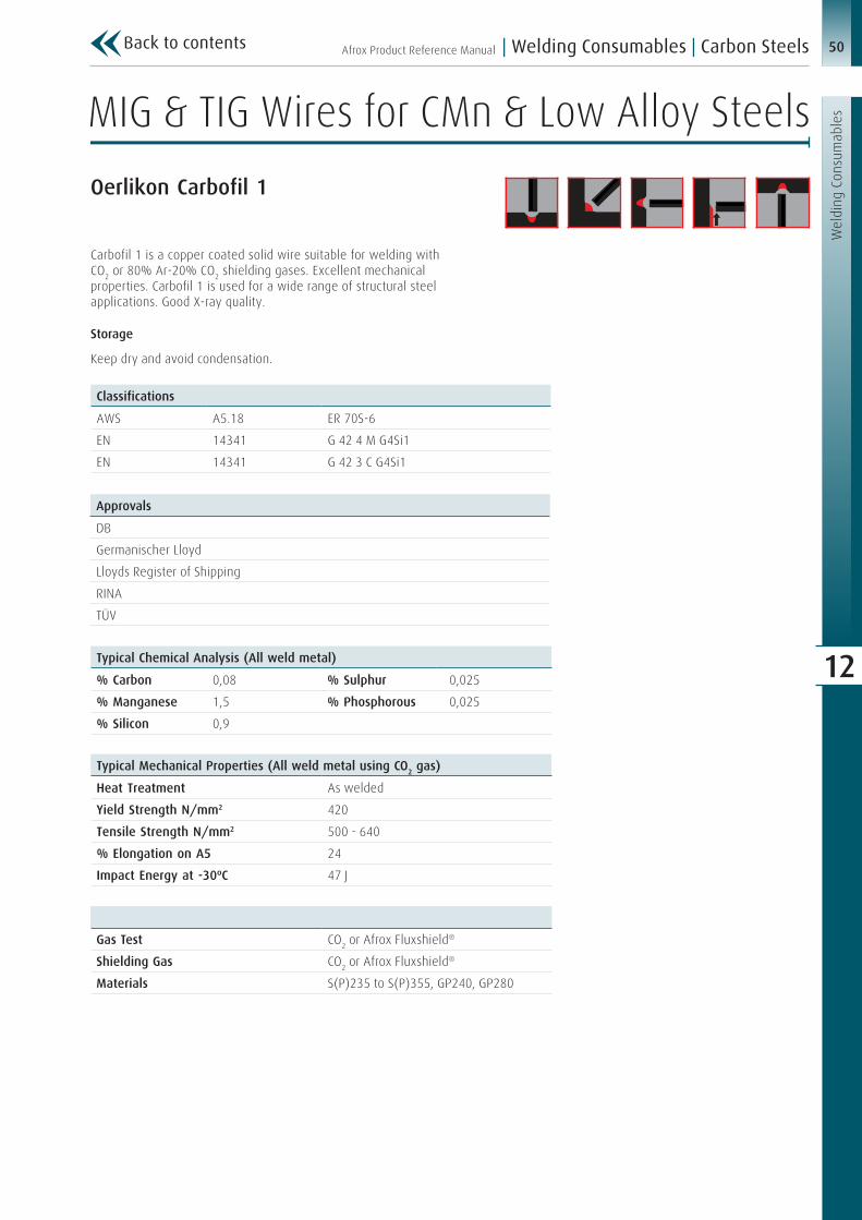
50Afrox Product Reference Manual
Wel
ding
Con
sum
able
s
| Welding Consumables | Carbon Steels
12
Oerlikon Carbofil 1
Carbofil 1 is a copper coated solid wire suitable for welding with CO2 or 80% Ar-20% CO2 shielding gases. Excellent mechanical properties. Carbofil 1 is used for a wide range of structural steel applications. Good X-ray quality.
Storage
Keep dry and avoid condensation.
Approvals
DB
Germanischer Lloyd
Lloyds Register of Shipping
RINA
TÜV
Typical Chemical Analysis (All weld metal)
% Carbon 0,08 % Sulphur ≤0,025
% Manganese 1,5 % Phosphorous ≤0,025
% Silicon 0,9
Typical Mechanical Properties (All weld metal using CO2 gas)
Heat Treatment As welded
Yield Strength N/mm2 420
Tensile Strength N/mm2 500 - 640
% Elongation on A5 24
Impact Energy at -30ºC 47 J
Classifications
AWS A5.18 ER 70S-6
EN 14341 G 42 4 M G4Si1
EN 14341 G 42 3 C G4Si1
Gas Test CO2 or Afrox Fluxshield®
Shielding Gas CO2 or Afrox Fluxshield®
Materials S(P)235 to S(P)355, GP240, GP280
MIG & TIG Wires for CMn & Low Alloy Steels
Back to contents

51 Afrox Product Reference Manual
Wel
ding
Con
sum
able
s
Welding Consumables | Carbon Steels |
12
Packing Data
Diameter (mm)
Pack Mass Drums (kg)
Item Number
1,0 150,0 W122103
1,2 150,0 W122104
1,0 300,0 W122113
1,2 300,0 W122114
1,0 500,0 W122123
1,2 500,0 W122124
Packing Data K300
Diameter (mm)
Pack Mass Spools (kg)
Item Number
0,8 15,0 W122001
0,9 15,0 W122002
1,0 15,0 W122003
1,2 15,0 W122004
1,6 15,0 W122005

52Afrox Product Reference Manual
Wel
ding
Con
sum
able
s
| Welding Consumables | Carbon Steels
12
Chemical Composition Requirements for Solid Electrodes and Rods
Electrode Classification %C %Mn %Si %S %P %Cu Other
US Metric
ER70S-2 ER48S-2 0,07 0,9 - 1,4 0,4 - 0,7 0,035 0,025 0,5 Ti 0,05 - 0,15, Zr 0,02 - 0,12, Al 0,05 - 0,15
ER70S-3 ER48S-3 0,06 - 0,15
0,9 - 1,4 0,45 - 0,75
0,035 0,025 0,5
ER70S-4 ER48S-4 0,07 - 0,15
1,0 - 1,5 0,65 - 0,85
0,035 0,025 0,50
ER70S-5 ER48S-5 0,07 - 0,19
0,9 - 1,4 0,3 - 0,6 0,035 0,025 0,5 Al 0,5 - 0,9
ER70S-6 ER48S-6 0,06 - 0,15
1,4 - 1,85 0,8 - 1,15 0,035 0,025 0,5
ER70S-7 ER48S-7 0,07 - 0,15
1,5 - 2,0 0,5 - 0,8 0,035 0,025 0,5
ER70S-G ER48S-G Not specified
Classification Designators
ER 70S-YX
ER Indicates a solid wire
70 or 48 The minimum tensile strength of the deposited weld metal. In all specified products in this standard, the minimum tensile strength is 70 000 psi or 480 MPa
S Solid electrode/wire, a ‘C’ would indicate a metal cored wire
Y This can be 2, 3, 4, 5, 6, 7 or ‘G’ as detailed in the table below
X This final ‘X’ shown in the classification represents a ‘C’ or ‘M’ which corresponds to the shielding gas with which the metal cored wire is classified. The use of ‘C’ designates 100% CO2 shielding, ‘M’ designates 75-80% Ar/CO2. Solid wires are classified using CO2
The solid electrodes (and rods) covered by this specification are classified according the following attributes:
Chemical composition of the electrode
Mechanical properties of the weld metal.
AWS A5.18 Specification for Carbon Steel Electrodes and Rods for Gas Shielded Arc Welding
Single values are maximums. Please consult specification for definitive values
Please Note: AWS now makes provision for metric values. The specification containing equivalent metric values is indicated by AWS A5.18M

53 Afrox Product Reference Manual
Wel
ding
Con
sum
able
s
Welding Consumables | Carbon Steels |
12
Afrox TM-791
TM-791 is a gas shielded flux cored wire for welding carbon- manganese steels having a tensile strength up to 620 MPa and where impact properties at sub-zero temperatures may be required. It also has low spatter levels and the slag is easy to remove. The wire is recommended for single- and multi-pass welding in all positions using a 75% Ar/25% CO2 argon-based mixed gas (Afrox Fluxshield®) or CO2. TM-791 has excellent
welder appeal with superior mechanical properties. It has a quiet soft arc with very low spatter and fume levels. Deposited weld metal has similar mechanical properties to that of a 7018 type MMA electrode. These features, along with the high deposition rates inherent in out-of-position welding, make TM-791 an excellent choice for shipbuilding, pressure vessel fabrication and structural welding.
Classifications
AWS A5.20 E7IT-1, E71T-1M
AWS A5.20 E71T-9, E71T-9M
Approvals
Lloyds Register of Shipping Grade 3YSH 10
American Bureau of Shipping 3SA, 3YSA HH,(75Ar/25CO2),3YSA HH (CO2)
Det Norske Veritas 111Y40MS (H10)
Bureau Veritas SA 3YM HH
Germanischer Lloyd 3YH10S
Typical Chemical Analysis (All weld metal)
Shielding Gas Fluxshield® CO2 Shielding Gas Fluxshield® CO2
% Carbon 0,022 0,021 % Sulphur 0,01 0,011
% Manganese 1,6 1,3 % Phosphorous 0,014 0,015
% Silicon 0,82 0,69
Typical Mechanical Properties (All weld metal using CO2 gas)
Shielding Gas Fluxshield® CO2
Yield Strength 592 MPa 546 MPa
Tensile Strength 662 MPa 605 MPa
% Elongation on 50 mm 26 28
Charpy V-Notch at -18˚C 80 J 95 J
Charpy V-Notch at -29˚C 68 J 69 J
Flux & Metal Cored Wires
Back to contents

54Afrox Product Reference Manual
Wel
ding
Con
sum
able
s
| Welding Consumables | Carbon Steels
12
Welding Data(DC+) Shielding Gas: Fluxshield®
Diameter (mm)
Position Current Deposition Rates (kg/h)
Electrode Stick Out (mm)Amps (A) Volts (V)
1,2 Flat/horizontal 250 26 4,1 12,0
1,2 Vertical-up/overhead
170 - 220 22 - 24 2,0 - 3,5 12,0
1,6 Flat 360 27 5,5 - 3,6 25,0
1,6 Horizontal 280 24 3,6 25,0
1,6 Vertical-up/overhead
215 - 245 22 - 23 2,6 - 3,0 25,0
Welding Data(DC+) Shielding Gas: CO2
Diameter (mm)
Position Current Deposition Rates (kg/h)
Electrode Stick Out (mm)Amps (A) Volts (V)
1,2 Flat/horizontal 260 27 4,1 12,0
1,2 Vertical-up/overhead
170 - 220 23 - 25 2,0 - 3,4 12,0
1,6 Flat 360 29 - 26 5,5 - 3,6 25,0
1,6 Horizontal 280 26 3,6 25,0
1,6 Vertical-up/overhead
215 - 245 24 - 25 2,6 - 3,0 25,0
Packing Data
Diameter (mm)
Pack Mass Drums (kg)
Item Number
1,2 15,0 W081051
1,6 15,0 W081052

55 Afrox Product Reference Manual
Wel
ding
Con
sum
able
s
Welding Consumables | Carbon Steels |
12
Afrox Coremax 71
Coremax 71 is a rutile type CO2 shielded flux cored wire for the welding of carbon-manganese steels. It is recommended for the all-positional welding of mild and low alloy steels with a tensile strength of up to 620 MPa for general-purpose fabrication. Coremax 71 also provides increased toughness at sub-zero temperatures.
Classifications
AWS A5.20 E71T-1
Typical Chemical Analysis (All weld metal)
% Carbon 0,04 % Sulphur 0,01
% Manganese 1,32 % Phosphorous 0,02
% Silicon 0,42
Typical Mechanical Properties (All weld metal using CO2 gas)
Yield Strength 540 MPa
Tensile Strength 580 MPa
% Elongation on 5d 28
Charpy V-Notch at -18˚C 65 J
Approvals
Det Norske Veritas
Bureau Veritas
Welding Data (DC+) Shielding Gas: CO2
Diameter (mm)
Position Current Deposition Rates (kg/h)
Electrode Stick Out (mm)
Amps (A) Volts (V)
1,2 Flat/horizontal 260 27 4,1 12,0
1,2 Vertical-up/overhead
170 - 220 23 - 25 2,0 - 3,4 12,0
1,6 Flat 360 29 5,5 25,0
1,6 Horizontal 280 26 3,6 25,0
1,6 Vertical-up/overhead
215 - 245 24 - 25 2,6 - 3,0 25,0
Typical Values
Packing Data
Diameter (mm)
Spool Mass (kg)
Item Number
1,2 15,0 W081130
1,6 15,0 W081131

56Afrox Product Reference Manual
Wel
ding
Con
sum
able
s
| Welding Consumables | Carbon Steels
12
Afrox Coremax 71 Plus
Coremax 71 Plus is a gas shielded flux cored wire for welding carbon-manganese steels, having a tensile strength of up to 620 MPa and where impact properties of sub-zero may be required. It has low spatter levels and the slag is easy to remove. The wire is recommended for single- and multi-pass welding in all positions using a 75% Ar, 25% CO2 argon based mixed gas (Afrox Fluxshield®) or CO2.
Classifications
AWS A5.20 E71T-1M
Typical Chemical Analysis (All weld metal)
% Carbon 0,04 % Sulphur 0,01
% Manganese 1,32 % Phosphorous 0,02
% Silicon 0,42
Typical Mechanical Properties (All weld metal using CO2 gas)
Yield Strength 540 MPa
Tensile Strength 580 MPa
% Elongation on 5d 28
Charpy V-Notch at -18˚C 65 J
Welding Data(DC+) Shielding Gas: 75% Ar/25% CO2 or CO2
Diameter (mm)
Position Current Deposition Rates (kg/h)
Electrode Stick Out (mm)Amps (A) Volts (V)
1,2 Flat/horizontal 260 27 4,1 12
1,2 Vertical-up/overhead
170 - 220 23 - 25 2,0 - 3,4 12
1,6 Flat 360 29 5,5 25
1,6 Horizontal 280 26 3,6 25
1,6 Vertical-up/overhead
215 - 245 24 - 25 2,6 - 3,0 25
Packing Data
Diameter (mm)
Spool Mass (kg)
Item Number
1,2 15,0 W081230
1,6 15,0 W081231
Approvals
Det Norske Veritas
Bureau Veritas

57 Afrox Product Reference Manual
Wel
ding
Con
sum
able
s
Welding Consumables | Carbon Steels |
12
Afrox S71T-11
Classifications
AWS A5.20 E71T-11
EN 17632-A T 42 Z W N 1 H10
Typical Chemical Analysis (All weld metal)
% Carbon 0,18 % Sulphur 0,012
% Manganese 1,0 % Phosphorous 0,012
% Silicon 0,25 % Aluminium 0,8
Typical Mechanical Properties (All weld metal using CO2 gas)
Yield Strength 430 MPa
Tensile Strength 520 MPa
% Elongation on 5d 23
Welding Data(DC+) Shielding Gas: CO2
Diameter (mm)
Current
Amps (A) Volts (V)
0,8 50 - 200 12 - 24
0,9 70 - 220 13 - 27
1,2 90 - 310 16 - 35
Typical Values
Packing Data
Diameter (mm) Spool Mass (kg) Item Number
0,8 4,5 W081004
0,9 4,5 W081009
1,2 4,5 W081016
S71T-11 is an open-arc (no shielding gas required) tubular wire which is exceptionally easy to use. It is recommended for use with smaller MIG machines or in areas where the provision of gas cylinders is not practical. S71T-11 has little tendency to burn through and is well suited for butt, fillet and lap joints on steel thicknesses of 1,6 mm to 10 mm. It is not recommended for welding steel thicknesses greater than 12 mm.

58Afrox Product Reference Manual
Wel
ding
Con
sum
able
s
| Welding Consumables | Carbon Steels
12Welding Data(DC+)
Diameter (mm)
Position Current Optimum Settings Deposition Rates (kg/h)
Electrode Stick Out (mm)Amps (A) Volts (V) Amps (A) Volts (V)
2,0 Flat/horizontal 290 - 370 31 330 30 5,0 - 7,3 50,0
2,4 Flat/horizontal 250 - 500 28 - 34 400 31 4,0 - 12,7 65,0
Classifications
AWS A5.20 E70T-4
EN 17632-A T 46 Z W N 4 H10
Typical Chemical Analysis (All weld metal)
% Carbon 0,27 % Phosphorous 0,008
% Manganese 0,45 % Aluminium 1,36
% Silicon 0,3 % Nickel 0,01
% Sulphur 0,004
Typical Mechanical Properties (All weld metal using CO2 gas)
Yield Strength 476 MPa
Tensile Strength 635 MPa
% Elongation on 50 mm 22
Packing Data
Diameter (mm)
Pack Mass (kg)
Package Item Number
2,0 22,0 Coil W081033
2,4 22,0 Coil W081011
2,4 270,0 Drum W081012
Approvals
American Bureau of Shipping E70T-4 (AWS A5.20)
Canadian Welding Bureau E4802T-4-CH
Afrox TM-44
TM-44 is an outstanding high deposition self-shielded tubular wire that is used to weld mild and medium carbon steels. It is ideal for either single- or multi-pass welding, and provides outstanding performance with deposition rates of up to 20 kg/h and deposition efficiencies of 84% or better. This electrode
produces a globular type transfer with an arc that is not affected by drafts or moderate wind. It is specifically designed to desulphurise the weld metal and resist cracking. The product is recommended for applications such as machine fabrication, certain ship equipment, industrial and heavy equipment repair.

59 Afrox Product Reference Manual
Wel
ding
Con
sum
able
s
Welding Consumables | Carbon Steels |
12
Afrox TM-121
TM-121 is a versatile tubular wire with excellent operator appeal because of its smooth arc, low spatter and overall ease of handling. With no shielding gas needed, it is a good choice for welding in hard-to-reach locations or where the provision of gas cylinders is not practical. It is a good wire for applications where windy or other adverse conditions prevail and where mechanical properties are of less concern. TM-121 has little tendency to burn through and is well suited for butt, fillet and lap joints
on steel thicknesses from 1,6-10 mm. It is not recommended for welding steel thicknesses greater than 12,7 mm. When welding on steels in the 10-19 mm thickness range, a preheat temperature of 160˚C is advisable. The wire is recommended for single-pass and limited multiple-pass welding in all positions, using no shielding gas.
Welding Data(DC+)
Diameter (mm)
Position Current Optimum Settings Deposition Rates (kg/h)
Electrode Stick Out (mm)Amps (A) Volts (V) Amps (A) Volts (V)
1,6 Flat/horizontal 125 - 300 19 - 20 230 17 0,5 - 3,3 12,0 - 19,0
1,6 Vertical/overhead
125 - 250 15 - 19 175 16 0,7 - 2,1 12,0 - 19,0
2,0 Flat/horizontal 175 - 350 16 - 22 275 19 1,1 - 3,0 12,0 - 19,0
Packing Data
Diameter (mm)
Pack Mass (kg)
Package Item Number
1,6 15,0 Spool W081013
2,0 15,0 Spool W081015
2,0 22,0 Coil W081014
Typical Chemical Analysis (All weld metal)
% Carbon 0,3 % Sulphur 0,003
% Manganese 0,49 % Phosphorous 0,009
% Silicon 0,15 % Aluminium 1,18
Typical Mechanical Properties (All weld metal using CO2 gas)
Yield Strength 442 MPa
Tensile Strength 628 MPa
% Elongation on 50 mm 21
Approvals
American Bureau of Shipping E71T-11 (AWS A5.20)
Classifications
AWS A5.20 E71T-11
EN 17632-A T 42 Z W N 1 H10

60Afrox Product Reference Manual
Wel
ding
Con
sum
able
s
| Welding Consumables | Carbon Steels
12
Metalloy 76 is a gas shielded metal cored wire designed for semi-automatic, automatic and robotic welding of low and medium carbon steels. The wire is recommended for single and limited multi-pass welding in the flat and horizontal positions. The recommended shielding gas is Afrox Fluxshield® (75% Ar, 25% CO2) at a gas flow rate of 17-24 ℓ/min. Metalloy 76 produces high quality welds with virtually no residual slag.
The product features lower spatter and higher strength levels. The higher manganese content gives increased deoxidisation and greater tolerance to mill scale and paint primers on the workpiece. Penetration is superior to that of solid wires, thereby minimising the cold lap problem on heavier sections of steels. Low spatter and low slag volume combine to greatly reduce clean-up costs.
Afrox Metalloy 76
Welding Data(DC+)
Diameter (mm)
Position Current Optimum Settings Deposition Rates (kg/h)
Electrode Stick Out (mm) Amps (A) Volts (V) Amps (A) Volts (V)
1,2 Flat/horizontal 200 - 350 27 - 35 300 32 2,7 - 7,0 12,0 - 19,0
1,6 Flat/horizontal 300 - 450 29 - 34 400 32 5,0 - 9,5 25,0 - 30,0
Packing Data
Diameter (mm) Spool Mass (kg) Item Number
1,2 15,0 W081029
1,6 15,0 W081028
Typical Chemical Analysis (All weld metal)
% Carbon 0,06 % Sulphur 0,019
% Manganese 1,64 % Phosphorous 0,012
% Silicon 0,75
Approvals
Lloyds Register of Shipping 3S,3440SH15
American Bureau of Shipping 3SA, 3YSM
Det Norske Veritas 111 Y40MS
Bureau Veritas SA 3YM
Germanischer Lloyd 3Y40H5S
Canadian Welding Bureau E4801C-6-CH
Typical Mechanical Properties (All weld metal using CO2 gas)
Yield Strength 559 MPa
Tensile Strength 628 MPa
% Elongation on 50 mm 27
Charpy V-Notch at -18˚C 72 J
Classifications
AWS A5.18 E70C-6M H4
EN 17632-A T 50 Z M M 2 H5

61 Afrox Product Reference Manual
Wel
ding
Con
sum
able
s
Welding Consumables | Carbon Steels |
12
Coremax 70
Coremax 70 is a metallic flux cored wire designed to be used with Ar/CO2 (Afrox Fluxshield®) for mild steel and 490 N/mm2 high tensile steel. Its deposition rate is 10-30% higher than a solid wire.
Multi-layer welding can be performed without removing slag. It is suitable for the multi-layer welding of thick plate welding in such applications as: steel structures, bridges, shipbuilding, vehicles and storage tanks, etc.
Welding Data(DC+)
Diameter(mm)
Current Flow Rate(ℓ/min)
Pack Mass(kg)
ItemNumberAmps (A) Volts (V)
1,2 200 - 300 28 - 38 15 - 25 15,0 W082230
1,6 250 - 400 28 - 38 20 - 25 15,0 W082231
Classifications
AWS A5.18 E70C-6M
EN 499 E 42 3 B 3 2 H10
Typical Mechanical Properties (All weld metal)
Tensile Strength 598 MPa
Yield Strength 559 MPa
% Elongation 26
Impact Energy at -20°C 57 J
Impact Energy at -30°C 45 J
Typical Chemical Analysis (All weld metal)
% Carbon 0,04 % Phosphorous 0,02
% Manganese 1,5 % Sulphur 0,01
% Silicon 0,63

62Afrox Product Reference Manual
Wel
ding
Con
sum
able
s
| Welding Consumables | Carbon Steels
12
Fluxofil 14 HD is a seamless copper coated rutile flux cored wire with a higher filling degree resulting in a higher current carrying capacity and high deposition rate. The welding speed is increased which leads to a saving of time and reduction of costs. It can be used in all positions with only one welding parameter setting (24 V, wire feed = 9 m/min, wire dia. 1,2 mm). Fluxofil 14 HD is used for manual welding, as well as in fully mechanised. It is recommended that a mixed shielding
gas be used and is characterised by low spatter loss, good slag removal and finely rippled, pore-free welds without undercut.
Storage
Keep dry and avoid condensation.
Oerlikon Fluxofil 14 HD
Packing Data
Diameter (mm) Item Number
1,2 W125133
1,6 W125134
Classifications
AWS A5.20 E71T-1 H4 / E71T-1M H4
EN 17632-A T 46 2 P M 1 H5
Typical Chemical Analysis (All weld metal)
% Carbon 0,05 % Silicon 0,55
% Manganese 1,2
Typical Mechanical Properties (All weld metal)
Heat Treatment As welded
Yield Strength N/mm2 460
Tensile Strength N/mm2 550 - 650
% Elongation on A5 22
Impact Energy at -20ºC 80 J
Approvals
American Bureau of Shipping Lloyds Register of Shipping
Bureau Veritas PRS
DB RS
Det Norske Veritas TÜV
Germanischer Lloyd UDT
Gas Test Afrox Fluxshield®
Shielding Gas Afrox Fluxshield®
Materials S(P)235-S(P)460, GP240-GP280Shipbuilding steels A,B,D,E,AH32 to EH36
Cored Wires for CMn & Low Alloy Steels
Back to contents

63 Afrox Product Reference Manual
Wel
ding
Con
sum
able
s
Welding Consumables | Carbon Steels |
12
Fluxofil 19 HD is a seamless copper coated rutile flux cored wire with an enhanced degree of fill. Due to its easily controllable weld pool, the welding characteristics are outstanding. It can be welded in all positions with only one parameter setting (24 V, wire feed 9 m/min, wire diameter 1,2 mm). The enhanced degree of filling results in increased current carrying capacity and deposition rate, thus increasing welding speed and leading
to a saving of time and costs. Low spatter loss, easy slag removal, smooth and finely rippled welds are produced without undercut into the base metal.
Storage
Keep dry and avoid condensation.
Oerlikon Fluxofil 19 HD
Classifications
AWS A5.20 E71T-1 H4
EN 17632-A T 46 2 P C 1 H5
Typical Chemical Analysis (All weld metal)
% Carbon 0,05 % Silicon 0,5
% Manganese 1,20
Typical Mechanical Properties (All weld metal)
Heat Treatment As welded
Yield Strength N/mm2 460
Tensile Strength N/mm2 550 - 650
% Elongation on A5 22
Impact Energy at -20ºC 80 J
Approvals
American Bureau of Shipping Lloyds Register of Shipping
Bureau Veritas PRS
DB RINA
Det Norske Veritas RS
Germanischer Lloyd TÜV
Packing Data
Diameter (mm) Item Number
1,2 W125150
1,6 W125152
Gas Test CO2
Shielding Gas CO2
Materials S(P)235-S(P)460, GP240-GP280Shipbuilding steels A,B,D,E,AH32 to EH36

64Afrox Product Reference Manual
Wel
ding
Con
sum
able
s
| Welding Consumables | Carbon Steels
12
In this specification, electrodes are classified on the basis of:
Whether CO2 is used as a shielding gas
Suitability for single or multiple-pass application
Type of current
Welding position
Mechanical properties of the deposited weld metal.
The system for identifying the electrode classification in AWS A5.20 follows, for the most part, the standard pattern used in other AWS filler metal specification.
AWS A5.20 Specification for Carbon Steel Electrodes for Flux Cored Arc Welding
Classification Designators
EXX-TWMJ HZ
E Designates an electrode
First X This designator is either 6 or 7. It indicates the minimum tensile strength (in psi x 10 000) of the weld metal when the sample is prepared in the manner prescribed by AWS A5.20
Second X Indicates the primary welding position for which the electrode is designed: 0 - flat and horizontal positions1 - all positions
T This designator indicates that the electrode is a flux cored electrode
W This designator is a number from 1 through 14 or the letter ‘G’ with or without an ‘S’ following. The number refers to the usability of the electrode. The ‘G’ indicates that the external shielding, polarity and impact properties are not specified. The ‘S’ indicates that the electrode is suitable for single-pass welding only. Please see table below for details
M An ‘M’ designator in this position indicates that the electrode is classified using 75-80% Ar-CO2 shielding gas. When this designator does not appear, it signifies that the shielding gas used for classification is CO2 or that the product is a self-shielded type
J Optional supplementary designator. Designates that the electrode meets the requirements for improved toughness by meeting a Charpy impact value of 27 J at -40˚C. Absence of the ‘J’ indicates normal impact requirements
HZ Optional supplementary designator. Designates that the electrode meets the requirements of the diffusible hydrogen test, (i.e 4, 8 or 16 ml of H2 per 100 g of deposited weld metal)
Wire Characteristics (Designator W)
AWS Classification a External Shielding Medium Current and Polarity
EXXT-1 (multiple-pass) CO2 b DC, electrode positive
EXXT-2 (single-pass) CO2 b DC, electrode positive
EXXT-3 (single-pass) None DC, electrode positive
EXXT-4 (multiple-pass) None DC, electrode positive
EXXT-5 (multiple-pass) CO2 b DC, electrode positive
EXXT-6 (multiple-pass) None DC, electrode positive
EXXT-7 (multiple-pass) None DC, electrode negative
EXXT-10 (single-pass) None DC, electrode negative
EXXT-11 (multiple-pass) None DC, electrode negative
EXXT-G (multiple-pass) c c
EXXT-GS (single-pass) c c
a, b and c refer to specification

65 Afrox Product Reference Manual
Wel
ding
Con
sum
able
s
Welding Consumables | Carbon Steels |
12
Afrox Sub 70-1 is a copper coated CMn submerged arc welding wire for joining carbon-manganese steels. It is widely used in structural steel work, i.e. shipbuilding, construction work, etc. The wire is suitable for both single-pass and multi-pass welding, and for welding butt and fillet joints where maximum ductility is required.
Afrox Sub 70-1
Packing Data
Diameter (mm) Item Number (25 kg coil)
2,0 W080011
2,4 W080012
3,15 W080013
4,0 W080014
Typical Chemical Analysis (Wire)
% Carbon 0,05 - 0,12 % Phosphorous 0,025 max
% Manganese 0,4 - 0,6 % Sulphur 0,025 max
% Silicon 0,07 max % Copper 0,3 max
Classifications
AWS A5.20 EL12
EN 756 Sl
Subarc Wires & Fluxes
Back to contents

66Afrox Product Reference Manual
Wel
ding
Con
sum
able
s
| Welding Consumables | Carbon Steels
12
Afrox Sub 70-2 is a copper coated low carbon, medium manganese wire that produces a higher tensile strength weld than Sub 70-1 depending on flux and procedure used. It is recommended for single- and multiple-pass welding.
Afrox Sub 70-2
Packing Data
Diameter (mm)
Item Number (25 kg coil)
Item Number(68 kg coils)
Item Number(450 kg pay-off spools)
Item Number(300 kg pay-off drums)
2,0 W080051 - W080056 W080061
2,5 W080052 - W080057 W080062
3,15 W080053 W080067 W080058 W080063
4,0 W080054 W080068 W080059 W080064
5,0 W080055 - W080060 -
Typical Chemical Analysis (Wire)
% Carbon 0,08 - 0,15 % Phosphorous 0,025 max
% Manganese 0,8 - 1,2 % Sulphur 0,025 max
% Silicon 0,1 - 0,2 % Copper 0,3 max
Classifications
AWS A5.17 EM12K
EN 756 S2

67 Afrox Product Reference Manual
Wel
ding
Con
sum
able
s
Welding Consumables | Carbon Steels |
12
Subarc S3Si is a copper coated submerged arc welding wire containing 1,5% manganese and 0,3% silicon. It is recommended for use with basic fluxes such as HPF-N90 where exceptional sub-zero impact properties are required.
Afrox Subarc S3Si
Packing Data
Diameter (mm) Item Number (27 kg coil)
2,4 W078116
3,2 W078118
4,0 W078120
Typical Chemical Analysis (All weld metal)
% Carbon 0,08 - 0,15 % Phosphorous < 0,3
% Manganese 1,4 - 1,8 % Sulphur < 0,01
% Silicon 0,2 - 0,35 % Copper < 0,01
Classifications
EN 756 S3Si
AWS A5.17 EH12K

68Afrox Product Reference Manual
Wel
ding
Con
sum
able
s
| Welding Consumables | Carbon Steels
12
Afrox Subarc Detron M1B is a copper coated CMn submerged arc welding wire for joining carbon-manganese steels. It is widely used in structural steelwork, shipbuilding, pressure vessel manufacture and construction. The wire is suitable for both single-pass and multi-pass welding and for welding butt and
fillet joints where higher mechanical properties are required. The higher silicon content improves weld pool fluidity. The wire can be used with basic, neutral and active fluxes. When used with active Mn and Si alloyed fluxes, it is limited to thicknesses below 25 mm.
Subarc Detron M1B
Packing Data
SAW Wire Current Pack Mass(kg)
Item Number
Diameter (mm) Amps (A) Volts (V)
3,2 500 28 27,0 W078385
4,0 550 28 27,0 W078386
Typical Chemical Analysis (All weld metal)
% Carbon 0,08 % Phosphorous 0,014
% Manganese 1,12 % Sulphur 0,005
% Silicon 0,17 % Copper 0,15
Classifications
AWS A5.17-89 EM 12K
EN 756 S2Si

69 Afrox Product Reference Manual
Wel
ding
Con
sum
able
s
Welding Consumables | Carbon Steels |
12
AWS A5.17 Specification for Carbon Steel Electrodes and Flux for Submerged Arc WeldingThe welding electrodes and fluxes covered by the specification are classified according to the following attributes:
The mechanical properties of the weld metal obtained with a combination of a particular flux and a particular classification of electrode
The condition of heat treatment in which those properties are obtained
The chemical composition of the electrode produced with a particular flux.
Example of AWS Classification:
F43 A2-EM12K is a complete designation for a flux-electrode combination. It refers to a flux that will produce weld metal which, in the as welded condition, will have a tensile strength of 430 to 560 MPa and Charpy V-Notch impact strength of at least 27 J at -20˚C when produced with an EM12K electrode
under the conditions called for in this specification. The absence of an ‘S’ in the second position indicates that the flux being classified is a virgin flux.
Please note: AWS now makes provision for metric values. The specification containing equivalent metric values is indicated by AWS A5.17M
Classification Designators
FS XYZ-ECXXX
F Indicates a submerged arc welding flux
S Indicates the flux contains crushed slag
X Indicates the minimum tensile strength of weld metal made in accordance with the welding conditions given in the specification
Y Designates the condition of heat treatment in which the tests were conducted. ‘A’ for as welded and ‘P’ for post weld heat treated
Z Indicates the lowest temperature at which the impact strength of the weld metal meets or exceeds 27 J i.e. Z No impact requirements0 0˚C 2 -20˚C 3 -30˚C 4 -40˚C 5 -50˚C 6 -60˚C
E Indicates a solid electrode; EC indicates a composite electrode
XXX Classification of the electrode used in producing the weld and given in the table below
Chemical Composition Requirements for Solid Electrodes
Electrode Classification
%C %Mn %Si %S %P %Cu
EL8 0,1 0,25 - 0,6 0,07 0,03 0,03 0,35
EL8K 0,1 0,25 - 0,6 0,1 - 0,25 0,03 0,03 0,35
EL12 0,04 - 0,14 0,25 - 0,6 0,1 0,03 0,03 0,35
EM12 0,06 - 0,15 0,8 - 1,25 0,1 0,03 0,03 0,35
EM11K 0,07 - 0,15 1,0 - 1,5 0,65 - 0,85 0,03 0,025 0,35
EM12K 0,05 - 0,15 0,8 - 1,25 0,10 - 0,35 0,03 0,03 0,35
EM13K 0,06 - 0,16 0,9 - 1,4 0,35 - 0,75 0,03 0,03 0,35
EM14K 0,06 - 0,19 0,9 - 1,4 0,35 - 0,75 0,025 0,025 0,35
EM15K 0,10 - 0,20 0,8 - 1,25 0,1 - 0,35 0,03 0,03 0,35
EH10K 0,07 - 0,15 1,3 - 1,7 0,05 - 0,25 0,025 0,025 0,35
EH11K 0,06 - 0,15 1,4 - 1,85 0,8 - 1,15 0,03 0,03 0,35
EH12K 0,06 - 0,15 1,5 - 2,0 0,2 - 0,65 0,025 0,025 0,35
EH14 0,10 - 0,2 1,7 - 2,2 0,1 0,03 0,03 0,35

70Afrox Product Reference Manual
Wel
ding
Con
sum
able
s
| Welding Consumables | Carbon Steels
12
Tri-Mark HPF-A72 Submerged Arc Flux
Tri-Mark HPF-A72 is an agglomerated flux with Mn and Si additions. HPF-A72 is a versatile flux with excellent weldability and easy slag removal; it is highly resistant to cracks and porosity and has a very good bead appearance. HPF-A72 is ideal for one-sided welding, double-sided welding, square edge joints, fillet welds and lap welds in structural and general engineering applications. It is recommended for welding inside grooves but is limited to material thicknesses below 25 mm. Due to the high oxidisation potential, it does not require any special base metal preparation and cleaning prior to welding.
Applications
Tri-Mark HPF-A72 is used to weld gas bottles, truck wheels, structural shapes, pipes, joining plates, light boilermaking and parts with small diameters.
Storage and Re-baking
The higher the basicity index of agglomerated fluxes, the more hygroscopic such a flux would be. All agglomerated fluxes should therefore be stored in conditions of less than 70% relative humidity. Welding with damp flux can cause porosity. Re-drying of flux suspected of being moist should be done for approximately two hours at about 300°C at a flux depth of about 25 mm. For many applications, it is not necessary to re-dry the flux.
Flux Characteristics
Maximum Welding Current 1 000 A
Polarity DC or AC
Welding Speed 1 300 mm/min
Classifications
AWS A5.17/ASME SFA 5.17 F7A2-EM12K
Typical Mechanical Properties
Yield Strength 426 MPa
Tensile Strength 519 MPa
% Elongation 29
Charpy V-Notch at -29ºC 23 J
Typical Chemical Analysis (All weld metal)
% Carbon 0,05 % Phosphorous 0,018
% Manganese 1,5 % Sulphur 0,025
% Silicon 0,8
Packing Data
Pack Mass (bags/kg) Item Number
25,0 W071403
Submerged Arc Fluxes
Back to contents

71 Afrox Product Reference Manual
Wel
ding
Con
sum
able
s
Welding Consumables | Carbon Steels |
12
Tri-Mark HPF-N90 and N90F are semi-basic agglomerated fluxes producing weld deposits with good mechanical properties at low temperatures. HPF-N90 and N90F have excellent weldability, easy slag removal in deep grooves, good resistance to cracking and porosity and excellent bead appearance. HPF-N90 and N90F flux can be used on multi-pass applications on unlimited thickness, with very little change in the chemical composititon of the weld metal.
Applications
Tri-Mark HPF-N90 and N90F can be used on structural steel, CrMo steel, high strength low alloy (HSLA) steels and quenched and tempered steels. The N90F grade has a finer particle size to
the N90 and can be used to rebuild small diameter shafts and journals such as those found on crankshafts.
Storage and Re-baking
The higher the basicity index of agglomerated fluxes, the more hygroscopic such a flux would be. All agglomerated fluxes should therefore be stored in conditions of less than 70% relative humidity. Welding with damp flux can cause porosity. Re-drying of flux suspected of being moist should be done for approximately two hours at about 300°C at a flux depth of about 25 mm. For many applications, it is not necessary to re-dry the flux.
Classifications
AWS A5.17/ASME SFA 5.17
F6A2-EL12 F7A2-EM13K F7A8-EC1 METALLOY EM12KS
F7A2-EM12K F8A2-EA 2-A2 F7A8-EC1 METALLOY EM13KS
F6A2-EM12K F9A2-EA 3-A3
F7P2-EM13K F9P2-EA 3-A3
Flux Characteristics
Maximum Welding Current 800 A
Polarity DC or AC
Basicity 1,4
Typical Mechanical Properties
EM12 EM12K EM13K EA2 EA3 EB2 EM12KS EM13KS
Yield Strength 393 MPa 426 MPa 410 MPa 499 MPa 565 MPa 655 MPa 408 MPa 430 MPa
Tensile Strength 476 MPa 519 MPa 525 MPa 577 MPa 655 MPa 720 MPa 490 MPa 530 MPa
% Elongation 30 29 30 2 26 23 27,8 26,5
Charpy V-Notch at -29ºC 61 J 66 J 98 J 57 J 56 J - - -
Charpy V-Notch at -18ºC - - - - - 51 J - -
Charpy V-Notch at -51ºC - - - - - - 96 J 110 J
Charpy V-Notch at -62ºC - - - - - - 56 J 84 J
Chemical Analysis (All weld metal)
EM12 EM12K EM13K EA2 EA3 EB2 EM12KS EM13KS
% Carbon 0,7 0,05 0,08 0,03 0,05 0,08 0,03 0,067
% Manganese 0,91 1,3 1,51 1,17 1,7 1,38 1,02 1,08
% Silicon 0,13 0,36 0,57 0,23 0,33 0,35 0,22 0,321
% Sulphur 0,03 0,022 0,019 0,03 0,021 0,013 0,009 0,011
% Phosphorous 0,024 0,02 0,015 0,03 0,029 0,019 0,012 0,015
% Molybdenum - - - 0,52 0,58 0,4 - -
% Chromium - - - - - 1,0 - -
% Copper - - - - - - 0,027 0,083
Tri-Mark HPF-N90 and N90F Submerged Arc Flux
Packing Data
Pack Mass (bags/kg) Item Number
25,0 W071401 (HPF-N90)
25,0 W071402 (HPF-N90F)

72Afrox Product Reference Manual
Wel
ding
Con
sum
able
s
| Welding Consumables | Carbon Steels
12
Typical Weld Metal Data
Product Composition of Weld Metal Deposited Hardness
% C
% Mn
% Si
% S
% P
% Mo
% Cr
% Ni
% Nb
% W
% V
HRc
McKay TA887-S 0,12 1,0 0,6 0,01 0,015 1,5 12,5 2,5 0,15 - 0,2 40
McKay TA8620-S 0,12 0,8 0,4 0,01 0,015 0,2 0,5 0,4 - - - 21
McKay TA861-S 0,15 0,9 0,5 0,01 0,015 0,6 1,7 - - - - 32
McKay TA 242-S 0,14 2,0 0,8 0,01 0,015 0,7 3,0 - - - - 40
McKay TA258-S 0,34 1,2 0,5 0,01 0,015 1,5 6,0 - - 1,4 - 54
McKay TA410-S 0,08 1,0 0,6 0,01 0,015 - 12,8 - - - - 36
McKay TA A250-S 0,19 1,0 0,5 0,01 0,015 - 12,3 - - - - 50
McKay TA 865-SMod 0,18 1,1 0,4 0,01 0,015 1,0 13,5 2,3 0,15 - 0,15 48
WASA 414MM-S 0,15 0,9 0,5 0,013 0,022 1,2 12,5 2,0 0,17 0,18 42 - 45
Lincore ER423L 0,15 1,2 0,4 0,01 0,02 1,0 11,5 2,0 - 0,15 42 - 45
Stoody Thermaclad 423L 0,15 1,2 0,5 0,012 0,022 1,0 11,7 2,0 - 0,15 43 - 45
EB3 0,1 0,96 0,16 0,01 0,019 1,08 2,15 - - - -
EM-12K 0,1 0,88 0,19 0,019 0,02 - - - - - -
McKay MK-N Submerged Arc Flux
McKay MK-N is totally neutral agglomerated flux, designed for welding with solid and tubular wires of the 400 series stainless steels. It can also be used with low alloy steel wires. It features clean slag removal with wires containing Nb and V, excellent recovery of the alloying elements from the tubular wires, such as Cr, Ni, Mo, Nb and V and accepts welding with twin-arc and oscillating technique, with currents up to 1 000 A. McKay MK-N flux should be used with wires containing at least 0,20% Si, in order to avoid porosity.
Applications
The main application of McKay MK-N flux is the rebuilding of steel mill roll with tubular and solid wires of the 400 series stainless steels. It can also be used to rebuild shafts, wheels and journals.
Storage and Re-baking
The higher the basicity index of agglomerated fluxes, the more hygroscopic such a flux would be. All agglomerated fluxes should therefore be stored in conditions of less than 70% relative humidity. Welding with damp flux can cause porosity. Re-drying of flux suspected of being moist should be done for approximately two hours at about 300°C at a flux depth of about 25 mm.
Packing Data
Pack Mass (bags/kg) Item Number
25,0 W071406

73 Afrox Product Reference Manual
Wel
ding
Con
sum
able
s
Welding Consumables | Carbon Steels |
12
Afrox Sub 70-1 is a copper coated CMn submerged arc welding wire for joining carbon-manganese steels. It is widely used in structural steel work, i.e. shipbuilding, construction work, etc. The wire is suitable for both single-pass and multi-pass welding, and for welding butt and fillet joints where maximum ductility is required.
Subarc Sub 70-1 Subarc Sub 70-1/HPF-N90Subarc Sub 70-1/MK-N Subarc Sub 70-1/HPF-A72
Typical Chemical Analysis (All weld metal)
% Carbon 0,078 % Phosphorous 0,009
% Manganese 0,46 % Sulphur 0,02
% Silicon 0,093 % Copper 0,2
Typical Mechanical Properties (All weld metal in the as welded condition)
Flux HPF-N90 HPF-A72 MK-N
Flux/Wire Combination F7A5-EL12 F7A0-EL12 F7A2-EL12
Tensile Strength 516 MPa 615 MPa 526 MPa
Yield Strength 425 MPa 519 MPa 441 MPa
% Elongation on 4d 31 27 32
Charpy Impact Value 43 J at -49ºC 40 J at -18ºC 51 J at -29ºC
Classifications
AWS A5.17-89 EL 12
EN 756 S1
Typical Chemical Analysis Weld Metal (SA 516 GR 70 Plate)
Flux HPF-N90 HPF-A72 MK-N
% Carbon 0,042 0,066 0,06
% Manganese 1,144 1,259 0,81
% Silicon 0,346 0,628 0,37
% Phosphorous 0,034 0,031 0,024
% Sulphur 0,025 0,026 0,019
% Copper 0,242 0,259 0,28
Packing Data
SAW Wire Current (DC+/AC) Pack Mass(kg)
Item Number
Diameter (mm) Amps (A) Volts (V)
2,0 400 28 25,0 W080011
2,4 450 28 25,0 W080012
3,2 500 28 25,0 W080013
4,0 550 28 25,0 W080014
Submerged Arc Wire & Flux Combinations
Back to contents

74Afrox Product Reference Manual
Wel
ding
Con
sum
able
s
| Welding Consumables | Carbon Steels
12
Afrox Sub 70-2 is a copper coated CMn submerged arc welding wire for joining carbon-manganese steels. It is widely used in structural steelwork, shipbuilding, pressure vessel manufacture and construction. The wire is suitable for both single-pass and
multi-pass welding and for welding butt and fillet joints where higher mechanical properties are required. The wire can be used with basic, neutral and active fluxes. When used with active Mn and Si alloyed fluxes, it is limited to thicknesses below 25 mm.
Packing Data
SAW Wire Current (DC+/AC) Item Number(25 kg spools)
Item Number(68 kg coils)
Item Number(450 kg bobbins)
Item Number(300 kg drums)
Diameter (mm)
Amps (A)
Volts (A)
2,0 400 28 W080051 - - -
2,4 450 28 W080052 - - W080062
3,2 500 28 W080053 W080067 - W080063
4,0 550 28 W080054 W080068 W080059 W080064
5,0 600 28 W080055 - W080060 -
Subarc Sub 70-2 Subarc Sub 70-2/HPF-N90Subarc Sub 70-2/MK-N Subarc Sub 70-2/HPF-A72Subarc Sub 70-2/HPF-N11X
Classifications
AWS A5.17-89 EH 12 K
EN 756 S2
Typical Chemical Analysis (All weld metal)
% Carbon 0,11 % Phosphorous 0,009
% Manganese 0,99 % Sulphur 0,023
% Silicon 0,137 % Copper 0,14
Typical Mechanical Properties (All weld metal in the as welded condition)
Flux HPF-N90 HPF-A72 MK-N HPF-N11X
Flux/Wire Combination F7A2-EM12K F7A2-EM12K F7A2-EM12K F7A4-EM12K
Tensile Strength 541 MPa 633 MPa 550 MPa 575 MPa
Yield Strength 424 MPa 524 MPa 452 MPa 467 MPa
% Elongation on 4d 30 26 30 32
Charpy Impact Value 68 J at -29ºC 40 J at -29ºC 85 J at -29ºC 74 J at -40ºC
Typical Chemical Analysis Weld Metal (SA 516 GR 70 Plate)
Flux HPF-N90 HPF-A72 MK-N HPF-N11X
% Carbon 0,069 0,064 0,072 0,082
% Manganese 1,224 1,573 1,2 1,036
% Silicon 0,292 0,748 0,408 0,332
% Phosphorous 0,022 0,031 0,029 0,016
% Sulphur 0,022 0,024 0,022 0,014
% Copper 0,168 0,182 0,53 0,172

75 Afrox Product Reference Manual
Wel
ding
Con
sum
able
s
Welding Consumables | Carbon Steels |
12
Subarc S3Si is a copper coated solid wire for submerged arc welding with 1,5% Mn and 0,2% Si content to be used with Mn-active fluxes for the welding of beams, tanks, pressure vessels and shipyards.
Subarc S3Si Subarc S3Si/HPF-N90Subarc Sub S3Si/HPF-A72 Subarc S3Si/MK-NSubarc S3Si/HPF-N11X
Typical Chemical Analysis (All weld metal)
% Carbon 0,11 % Phosphorous 0,001
% Manganese 1,7 % Sulphur 0,005
% Silicon 0,32 % Copper 0,1
Classifications
AWS A5.17-89 EM12K
EN 756 S3Si
Packing Data
SAW Wire Current (DC+/AC) Pack Mass(kg)
Item Number
Diameter (mm) Amps (A) Volts (V)
2,4 350 28 27,0 W078116
3,2 450 28 27,0 W078118
4,0 600 30 27,0 W078120
Typical Chemical Analysis Weld Metal (SA 516 GR 70 Plate)
Flux HPF-N90 HPF-A72 MK-N HPF-N11X
% Carbon 0,068 0,076 0,089 0,072
% Manganese 1,875 1,89 1,621 1,75
% Silicon 0,5 0,76 0,546 0,67
% Phosphorous 0,031 0,033 0,027 0,029
% Sulphur 0,012 0,01 0,011 0,01
% Copper 0,09 0,077 0,067 0,075
Typical Mechanical Properties (All weld metal in the as welded condition)
Flux HPF-N90As Welded
HPF-A72As Welded
MK-NAs Welded
HPF-N11XAs Welded
HPF-N11XPWHT 1 hr @ 690ºC
Flux/Wire Combination F7A2-EH12K F7A2-EH12K F7A2-EH12K F7A8-EH12K F7P8-EH12K
Tensile Strength 566 MPa 642 MPa 592 MPa 567 MPa 638 MPa
Yield Strength 445 MPa 540 MPa 493 MPa 464 MPa 531 MPa
% Elongation on 4d 31 30 31 31 29
Charpy Impact Value 91 J at -29ºC 62 J at -29ºC 145 J at -29ºC 29 J at -62ºC 7 J at -62ºC

76Afrox Product Reference Manual
Wel
ding
Con
sum
able
s
| Welding Consumables | Carbon Steels
12
Typical Chemical Analysis (All weld metal)
% Carbon 0,04 - 0,15 % Sulphur 0,035 max
% Manganese 0,35 - 0,60 % Phosphorous 0,04 max
% Silicon 0,03 max % Copper 0,35 max
Typical Physical Properties
Melting Range 1 490ºC
Approximate Tensile Strength of Deposited Metal 386 MPa
Approximate Brinell Hardness 120 HB
Brazing/Welding Parameters
Process Oxy-acetylene
Flame Setting Neutral
Flux Not required
Packing DataTIG (DC-)
Diameter (mm)
Consumable Length (mm)
Pack Mass (kg)
Item Number
1,6 750 5,0 W000040
2,5 750 5,0 W000045
3,2 750 5,0 W000041
5,0 750 5,0 W000042
Afrox Copper Coated Rod (CCR)
A general purpose low carbon steel gas welding rod which is copper coated to reduce corrosion. It is recommended for oxy-acetylene welding of mild steel and is widely used in sheet metal work, the heating and ventilation industries, car body repairs, welder training schools and for low pressure piping and plumbing.
Oxy-Fuel & Gas Welding Rods
Back to contents

77 Afrox Product Reference Manual
Wel
ding
Con
sum
able
s
Welding Consumables | Carbon Steels |
12
Classifications
AWS A5.4 R60
Typical Chemical Analysis (All weld metal)
% Carbon 0,12
% Manganese 1,00
% Silicon 0,12
Typical Mechanical Properties (All weld metal)
Tensile Strength >410 MPa
% Elongation >20
Packing DataTIG (DC-)
Diameter (mm) Pack Mass (kg) Item Number
2,0 5,0 W078368
Afrox R60 is a solid wire electrode for oxy-fuel welding of mild steels. For best results, use a neutral flame setting.
Afrox R60

78Afrox Product Reference Manual
Wel
ding
Con
sum
able
s
| Welding Consumables | Carbon Steels
12
Classes
MMA Electrodes C1 C2 C3 C4 C5
Solid Wires S1 S2 S3 S4
Cored Wires T1 T2 T3 T4
Fluxes F1 F2
Mechanically certified electrodes and wires are required by fabricators building and repairing components destined primarily for the petrochemical industry. Certification takes place in terms of the American ANSI/AWS A5.01 specification. A short description of the requirements is detailed below.
The certification of the consumable is based on two aspects:
The lot classification
The level of testing.
The consumables are broken into four primary groups:
Coated manual metal arc electrodes
Solid wires and rods
Flux and metal cored wires
Fluxes for submerged arc welding and brazing.
Lot Classification (Class)
The lot classification basically specifies a number of aspects which take place during the manufacturing operation to closely monitor the quality and to be able to clearly identify a production batch of consumables. The classification system is given in the table below:
Mechanically Certified Consumables
Generally, MMA electrodes produced by Afrox are manufactured to class C3, and MIG and TIG wires to class S1 and S3 respectively.
The definition for class C3 is:
A class C3 lot of electrodes is the quantity, not exceeding 45 000 kg, of any one size and classification (i.e. 7018-1) produced in 24 hours of consecutively scheduled production (consecutive normal working shifts). Class C3 electrodes shall be produced from covering (i.e. flux) identified by wet mix or controlled chemical composition and core wire identified by heat or cast number or chemically controlled composition.
The definition for class S1 is:
A class S1 lot of bare solid wires and rods is the manufacturer’s standard lot, as defined in the manufacturer’s QA programme (this in the case of Afrox is the heat or cast number which refers in terms of MIG 6000 and TIG 70S-6 to 100 000 kg of material).
The definition for class S3 is:
A class S3 lot of bare solid electrodes and rods, brazing and braze welding filler metal, and consumable inserts is the quantity of one size produced in one production cycle from one heat.
Level of Testing (Schedule)
The level of testing is selected by the purchaser and there are six levels or schedules, i.e. F, G, H, I, J and K. The most commonly used for both electrodes and wires is Schedule I. Schedule I requires the following tests to be carried out and certified for MMA electrodes:
Chemical analysis
Tensile properties (i.e. 0,2% proof stress, tensile strength and % elongation)
Charpy V-Notch impact properties
X-ray soundness
Moisture content (of the flux coating).
The purchaser would therefore specify consumables to be supplied in terms of for example class C3 schedule I or class C4 schedule J, etc.
A list detailing the Afrox products currently mechanically certified in terms of ANSI/AWS A5,01 is given in the table below:
Packing Data (7018-1)
Diameter (mm) Class Schedule Package Type Item Number
2,5 C3 I Box W075282
3,15 C3 I Box W075283
4,0 C3 I Box W075284
5,0 C3 I Box W075285
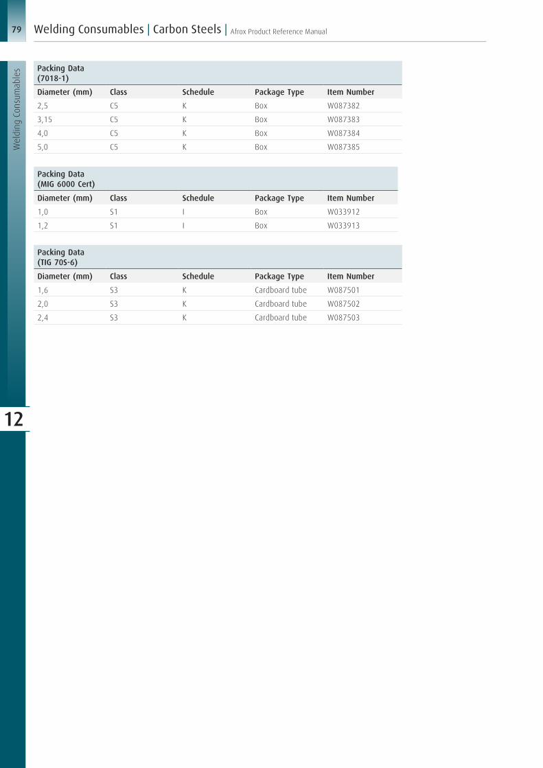
79 Afrox Product Reference Manual
Wel
ding
Con
sum
able
s
Welding Consumables | Carbon Steels |
12
Packing Data(MIG 6000 Cert)
Diameter (mm) Class Schedule Package Type Item Number
1,0 S1 I Box W033912
1,2 S1 I Box W033913
Packing Data(TIG 70S-6)
Diameter (mm) Class Schedule Package Type Item Number
1,6 S3 K Cardboard tube W087501
2,0 S3 K Cardboard tube W087502
2,4 S3 K Cardboard tube W087503
Packing Data (7018-1)
Diameter (mm) Class Schedule Package Type Item Number
2,5 C5 K Box W087382
3,15 C5 K Box W087383
4,0 C5 K Box W087384
5,0 C5 K Box W087385
Recommended