WATER DISTRIBUTION SYSTEM SPECIFICATIONS
PUBLIC WATER SUPPLY DISTRICT NO. 2
OF ST. CHARLES COUNTY, MISSOURI
100 WATER DRIVE
O’FALLON, MISSOURI 63368
Revised July 2013

i PWSD No. 2 of St. Charles County, MO Water Distribution System Specifications
TABLE OF CONTENTS DEFINITIONS ........................................................................................................ ii ARTICLE I. GENERAL REQUIREMENTS ................................................... I:1
SECTION 1.01 STANDARDS AND CONFORMANCE .......................................................................................... I:1 SECTION 1.02 CONTRACTOR QUALIFICATIONS ............................................................................................. I:2 SECTION 1.03 SITE WORK AND PREPARATION ............................................................................................. I:2 SECTION 1.04 DRAINAGE ............................................................................................................................. I:3 SECTION 1.05 OBSTRUCTIONS OF WATER MAIN .......................................................................................... I:3 SECTION 1.06 SEPARATION OF WATER MAIN, SEWERS, AND OTHER UTILITIES ........................................... I:3 SECTION 1.07 QUALITY AND HANDLING OF MATERIALS ............................................................................. I:3 SECTION 1.08 WORK ADJACENT TO AND/OR CROSSING RIGHTS-OF-WAY ................................................... I:4 SECTION 1.09 CREEK CROSSINGS ................................................................................................................. I:5 SECTION 1.10 STAKING ................................................................................................................................ I:5 SECTION 1.11 GRANULAR MATERIAL .......................................................................................................... I:5 SECTION 1.12 TRENCH EXCAVATION AND BACKFILLING ............................................................................. I:5 SECTION 1.13 SITE CLEAN UP AND RESTORATION ....................................................................................... I:6 SECTION 1.14 AS-BUILT DRAWINGS ............................................................................................................ I:7
ARTICLE II. WATER MAIN ........................................................................... II:1
SECTION 2.01 PIPE AND FITTINGS ............................................................................................................... II:1 SECTION 2.02 FITTINGS AND FITTING RESTRAINT ....................................................................................... II:3 SECTION 2.03 POLYETHYLENE ENCASEMENT.............................................................................................. II:4 SECTION 2.04 BURIED BELOW TAPE ........................................................................................................... II:4 SECTION 2.05 TRACER WIRE ....................................................................................................................... II:5 SECTION 2.06 CASING PIPES ........................................................................................................................ II:5 SECTION 2.07 WATER SERVICE CONNECTIONS ........................................................................................... II:6
ARTICLE III. WATER DISTRIBUTION SYSTEM COMPONENTS ........... III:1
SECTION 3.01 VALVES ............................................................................................................................... III:1 SECTION 3.02 TAPPING SLEEVES AND VALVES .......................................................................................... III:2 SECTION 3.03 FIRE HYDRANTS .................................................................................................................. III:3 SECTION 3.04 AIR RELEASE DEVICES ........................................................................................................ III:4
ARTICLE IV. TESTING ................................................................................... IV:1
SECTION 4.01 DISINFECTION ......................................................................................................................IV:1 SECTION 4.02 PRESSURE TESTING ..............................................................................................................IV:1 SECTION 4.03 LEAKAGE TESTING ..............................................................................................................IV:1 SECTION 4.04 FLUSHING ............................................................................................................................IV:2 SECTION 4.05 BACTERIOLOGICAL TESTING ................................................................................................IV:2 SECTION 4.06 FINAL INSPECTION AND TRACER WIRE TESTING .................................................................IV:3
APPENDIX A
APPENDIX B

ii PWSD No. 2 of St. Charles County, MO Water Distribution System Specifications
DETAILS DETAIL A – PAGE 1 OF 2 TYPICAL TRENCH SECTION FOR PVC PIPE
DETAIL A – PAGE 2 OF 2 TYPICAL TRENCH SECTION FOR DUCTILE IRON PIPE
DETAIL B – PAGE 1 OF 3 FIRE HYDRANT DETAIL
DETAIL B – PAGE 2 OF 3 FIRE HYDRANT DETAIL
DETAIL B – PAGE 3 OF 3 FIRE HYDRANT DETAIL
DETAIL C HORIZONTAL THRUST BLOCKING
DETAIL D GATE VALVE DETAIL
DETAIL E CROSS BLOCK
DETAIL F TYPICAL WATER MAIN TERMINATION DETAIL
DETAIL G AUTOMATIC AIR RELEASE DEVICE
DETAIL H TYPICAL WATER BORE AND ENCASEMENT
DETAIL I – PAGE 1 OF 2 SMALL COURT DETAIL
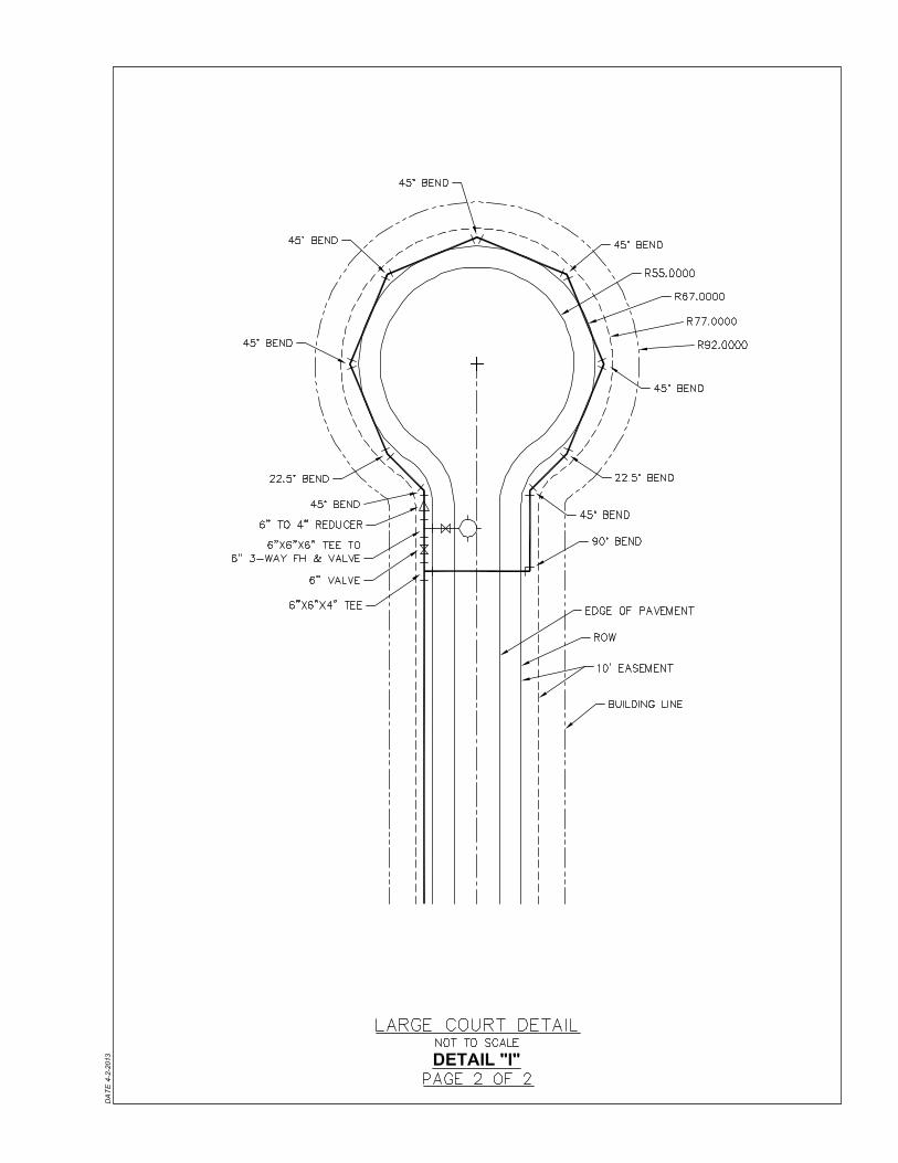
DETAIL I – PAGE 2 OF 2 LARGE COURT DETAIL
Contractor ..................Person or firm responsible for the construction of Improvements.
DEFINITIONS
Design ........................Plans sealed by Engineer and approved for construction by District and MoDNR.
Developer ...................Individual(s) or organization(s) proposing Improvements.
District........................Public Water Supply District No. 2 of St. Charles County, Missouri.
District Engineer ........Appointed representative of District.
Engineer .....................Person or firm preparing Design.
Improvements ............Pumping stations, extensions, relocations, upgrades, or any physical modification of or addition to an existing water distribution system and any related appurtenances.
MoDNR......................Missouri Department of Natural Resources.
(The remainder of this page intentionally left blank)

I:1 PWSD No. 2 of St. Charles County, MO Water Distribution System Specifications
Article I.
The following requirements apply to all Articles of these specifications. Additional requirements may be necessary for each individual section and additional requirements may be set forth by the District Engineer.
GENERAL REQUIREMENTS
Design, installation, and maintenance of Improvements shall be in accordance with the latest version of the District’s “GUIDELINES FOR WATER DISTRIBUTION SYSTEM AND SANITARY SEWER COLLECTION SYSTEM IMPROVEMENTS”.
All Improvements shall be designed in accordance with these specifications and any applicable federal, state, and local requirements.
In cases where project specific specifications are approved by the District Engineer the project specifications shall govern.
In addition to the requirements under this specification, Improvements shall comply with the most recent MoDNR “Design Guide for Community Water Systems” requirements.
Failure to comply with these specifications, the “GUIDELINES FOR WATER DISTRIBUTION SYSTEM AND SANITARY SEWER COLLECTION SYSTEM IMPROVEMENTS”, or any other applicable documents shall result in rejection of the Improvements by the District.
Section 1.01 Standards and Conformance
Materials for use at any location in the water distribution system shall meet the requirements as set forth in this specification. Where references are made to standards such as AWWA, ANSI, ASTM, etc. it shall be understood that such references are to the latest edition of such standards. When requested by the District, Contractor shall furnish affidavits from their suppliers certifying that materials conform to stated standards before being incorporated into the work.
Materials
Where materials are specified by brand name and model, followed by the words “or approved equal”, the information concerning an “approved equal” product must be submitted to the District and a written statement of approval by the District or its assigned representative must be issued before such material may be used. In all cases, approval of such alternate products shall be at the sole discretion of the District or its assigned representative.
The work covered by this specification shall consist of furnishing all specified materials with all necessary equipment, machinery, tools, and labor, and performing all work required to install and/or construct the Improvements with all directives or modifications and these specifications, all to be; complete, in place, accepted, and ready for use.
Installation

I:2 PWSD No. 2 of St. Charles County, MO Water Distribution System Specifications
District staff or its representatives, independent testing laboratories, and governmental agencies with jurisdictional interests will have access to the Site and the Work for their observation, inspection, and testing. Contractor shall provide them proper and safe conditions for such access and advise them of Contractor’s safety procedures and programs so that they may comply therewith as applicable.
Inspection, Tests, and Acceptance or Rejection of Defective Work
Contractor shall be responsible for arranging and obtaining and shall pay all costs in connection with any inspections, tests, or approvals required for District’s acceptance of materials or equipment to be incorporated in the work; or acceptance of materials, mix designs, or equipment submitted for approval prior to Contractor’s purchase thereof for incorporation in the work.
If any work (or the work of others) that is to be inspected, tested, or approved is covered by Contractor without concurrence of District staff or its representatives, Contractor shall, if requested by District staff, uncover such work for observation. Uncovering work shall be at Contractor’s expense.
Promptly after receipt of written notice from the District or its representatives of defective work, Contractor shall correct all defective work, whether or not fabricated, installed, or completed, or if the work has been rejected by the District, remove it from the project and replace it with work that is not defective. Contractor shall pay all claims, costs, losses, and damages (including but not limited to all fees and charges of engineers, architects, attorneys, and other professionals and all court or arbitration or other dispute resolution costs) arising out of or relating to such correction or removal (including but not limited to all costs of repair or replacement of work of others).
Field changes shall be made only with the specific permission of the District Engineer and Engineer.
Section 1.02 Contractor Qualifications
To demonstrate Contractor’s qualifications to perform the Work, within five (5) days of the District’s request, the Contractor shall submit written evidence such as financial data, previous experience, present commitments, and three (3) projects performed within the past three (3) years, relating to construction of water distribution improvements of a similar diameter, material, and scope with project references and contacts.
Section 1.03 Site Work and Preparation
Prior to starting the various Improvements, the Contractor shall notify the District a minimum of one (1) week prior to the start of construction. After doing so, the Contractor shall clear the route of all trees, shrubs, and other objects or materials which may directly interfere with the construction. All trees, shrubs, bushes, etc., which will not interfere with the construction shall be protected from damage.
Work preparations shall include having all necessary materials and equipment at the site in working condition, and an adequate labor force at the site and completely

I:3 PWSD No. 2 of St. Charles County, MO Water Distribution System Specifications
instructed and prepared to perform the work to completion. The Contractor shall notify all utility companies or organizations of work and shall request field markings of their respective facility locations prior to starting any work.
Section 1.04 Drainage
The Contractor shall control the grading in the vicinity of the pipe trenches so that the surface of the ground will be properly sloped to prevent water from running into the excavated areas, where possible. Any water or other liquid wastes which accumulate in the excavated areas shall be promptly removed.
Section 1.05 Obstructions of Water Main
Where improvements, such as but not limited to retaining walls, tie-backs, and storm sewers greater than 24”, are to be built over the water main, the main shall be placed in casing pipe as specified in Section 2.06. The determination of what will require the main to be placed in a casing pipe is at the discretion of the District Engineer.
Section 1.06 Separation of Water Main, Sewers, and Other Utilities
Water mains shall be laid at least ten feet horizontally from any existing or proposed sanitary or storm sewer. The distance shall be measured edge to edge. In cases where it is not practical to maintain a ten foot separation, deviations may be made on a case-by-case basis, if supported by data from the Engineer and approved by the District Engineer and MoDNR. Such deviation may allow installation of the water main closer to a sewer, provided that the water main is laid on a separate trench or on an undisturbed earth shelf located on one side of the sewer and in either case, at such elevation that the bottom of the water main is at least 18 inches above the top of the sewer.
Water mains crossing sewers shall be laid to provide a minimum vertical clear distance of 18 inches between the outside of the water main and the outside of the sewer. This shall be the case where the water main is either above or below the sewer. At crossings, the full length of water pipe shall be located so both joints will be as far from the sewer as possible.
Separation between water mains and all other utilities shall be a minimum of 2 feet horizontally and 18 inches vertically, or as required by the District Engineer.
Section 1.07 Quality and Handling of Materials
All materials used for each Improvements project shall be new. Damaged or unsound pipe, fittings, and accessories of whatever nature shall be rejected and removed from the site immediately.
All pipe, fittings, valves and other accessories, shall be unloaded, stored, re-handled, and installed by methods in such a manner as to ensure their final location in a sound and undamaged condition, conforming in all respects to specified requirements. Under no circumstances shall pipe, fittings, valves, or other accessories, be dropped to the ground, or otherwise subjected to possible damage from impact or shock. Such materials shall be loaded by lifting with machine or hoist, or by skidding. Pipe handled on skidways shall not be skidded or rolled against other pipe.

I:4 PWSD No. 2 of St. Charles County, MO Water Distribution System Specifications
Under all circumstances, all materials for use shall be handled in a workman-like manner, using the necessary manpower and equipment to perform the task in accordance with the manufacturer's recommendations.
All materials shall be handled in such manner that neither the coatings nor linings are damaged. Hooks for insertion into the ends of the pipes, fittings, valves, and other accessories, shall have broad, well-padded contact surfaces, and shall be of such design and size that uniform support will be provided. Under most circumstances, damage to outside coatings are repairable, and the necessary repairs shall be properly made prior to installation. Damage to interior linings is not considered repairable, and therefore, the damaged item shall be replaced.
Proper equipment, tools, facilities, and methods satisfactory to the District, shall be provided and used by the Contractor for the safe handling of all materials. Fittings, valves, and other accessories shall be carefully lowered into the trench or excavation, piece by piece, to protect coatings and linings. Under no circumstances shall any materials be dropped or dumped into the trench. All joints shall be made as specified in Section 2.01. Each piece of pipe and all fittings, valves, etc. shall be checked and cleared of debris prior to being put in place. All gaskets shall be checked and cleaned of oil, grease, dirt, etc. before being inserted. All bolted joints shall be rechecked for operation and bolt tightness prior to installation.
All open ends of pipe, fittings, etc., shall be carefully sealed with appropriately sized mechanical joint plugs or caps at the end of each day’s work to prevent entrance of animals, water, and other foreign matter. Mechanical joint plugs or caps and the appropriate gasket and gland packs shall be utilized for sealing.
Section 1.08 Work Adjacent to and/or Crossing Rights-of-Way
All work to be performed within the road right-of-way limits shall be performed in strict accordance with the road authority’s requirements. The Contractor shall obtain the necessary permits for all work prior to starting any construction. All permits must be displayed as required with two (2) copies provided to the District.
The Contractor shall comply with all standards of the latest version of the Manual on Uniform Traffic Control Devices as published by the Federal Highway Administration and any additional requirements set forth by the road authority.
The crossings shall be machine bored with simultaneous installation of the encasement. Boring without the concurrent installation of the encasement tube will not be permitted. In addition to the requirements outlined in this Specification, any water main crossing a road right of way shall be constructed in accordance with all permit requirements provided by the road authority.
Following completion of the machine bored crossing, the ends of the pipe casings shall be sealed and all bore pit or other required excavation shall be suitably backfilled to grade. For requirements for the carrier pipe and casing pipe crossing road rights-of-ways see Section 2.01 and Section 2.06, respectively.

I:5 PWSD No. 2 of St. Charles County, MO Water Distribution System Specifications
Section 1.09 Creek Crossings
Where water mains cross creeks, all piping shall be restrained joint piping as specified in Section 2.01. Restrained joints and fittings, as specified in Section 2.02, shall be provided. In certain cases, as determined by the District Engineer, steel casing pipe may be required as outlined in Section 2.06 of these Specifications. The determination of what constitutes a creek and the necessity for steel casing pipe shall be made by the District Engineer.
Surface water crossings shall be in accordance with MoDNR requirements as given in Appendix B of these Specifications. Any required U.S Army Corps of Engineers permits must be acquired by the Developer with two (2) copies provided to the District. All requirements of such permits must be met by the Contractor.
Section 1.10 Staking
Staking shall be provided before the start of and during construction. Staking shall be completed by the Developer’s Engineer or land surveyor and shall be completed by or directly supervised by a professional land surveyor licensed in the State of Missouri. All staking and survey shall be performed using US State Plane 1983, zone Missouri East 2401, datum NAD83, with altitude measured from mean sea level and units of feet.
Stakes shall be placed to indicate the road right of way or the limits of the easements at a maximum spacing of 100 feet. The stakes shall be placed along the centerline of the proposed water main or on a fixed offset at intervals not to exceed 100 feet. Stakes shall be placed for all fittings, valves, fire hydrants and other appurtenances. All stakes shall be clearly marked to identify items such as valves, bends, or fire hydrants, as well as centerline, station, offset, easement, etc. For valves, fire hydrants and temporary blowoff assemblies, the stakes shall have the final grade noted on them such that all valve boxes, fire hydrants and blowoff assemblies can be set to the proper height to accommodate the final grading.
Cuts shall be marked on the laths placed as stakes. The cuts shown shall be the distance from the existing ground surface to the outside bottom of the water main.
Section 1.11 Granular Material
Where required per these Specifications, Granular Material shall be 3/4” minus crushed limestone and screenings and shall be compacted to 95% per Standard Proctor Test Method (ASTM D698). The Contractor shall provide at the Contractor’s cost independent third party compaction testing by a testing firm agreeable to the District.
Section 1.12 Trench Excavation and Backfilling
Trenches for water mains shall have a minimum width of the pipe O.D. plus 12 inches. The finished cover over water mains shall be a minimum of 3’-6” and a maximum of 6’-0”.

I:6 PWSD No. 2 of St. Charles County, MO Water Distribution System Specifications
For PVC pipe, the trench depth shall be excavated 6” deeper than the proposed bottom of the pipe to allow for 6” of Granular Material bedding. The PVC pipe shall also have the Granular Material placed to a level 6” above the top of the pipe with care taken to fill all void spaces beneath the pipe. The Granular Material shall be placed as shown on Detail A of these specifications.
For ductile iron pipe, if the trench bottom is stable and suitable earth, the pipe may be placed on the earth trench bottom. If the trench bottom contains stones larger than 2” in any length or solid rock, the trench shall be excavated 6” deeper than the proposed pipe bottom and 6” of Granular Material bedding shall be placed before the pipe is laid. The ductile iron pipe shall then have compacted backfill of clean earth or Granular Material placed to a level 6” above the top of the pipe.
If the trench bottom contains frozen material, excessive moisture, debris or other deleterious material, the trench shall be excavated 6” or more deeper than the proposed pipe bottom and backfilled to the desired grade with Granular Material. For all pipe, bell holes in the trench bottom shall be provided to allow full contact of the pipe with the trench bottom.
Backfill for all pipes under roadways or parking lots shall consist of Granular Material carefully placed to avoid future settlement from 6” above the top of the pipe to the finished grade or as specified by the governing road authority.
In other areas, for pipe 12” and smaller, the backfill shall be soil meeting ASTM D2487 soil classification groups GW, GP, SW, SP, GM, GC, SM, SC, ML, and CL free of stones larger than 6” in any length, debris, waste, frozen materials, vegetation and other deleterious matter.
For pipes larger than 12”, not under roadways or parking lots, the backfill shall be soil meeting ASTM D2487 soil classification groups GW, GP, SW, SP, GM, GC, SM, and SC free of stones larger than 6” in any length, debris, waste, frozen materials, vegetation and other deleterious matter.
The liquid limit and plasticity index shall not exceed 45 and 25, respectively, for the silt and clay materials.
Backfill of all pipe shall be well compacted by mechanical means. Any completed areas that show settlement shall be promptly re-backfilled with compacted clean earth, as specified above, or compacted Granular Material as required for the initial backfill.
Section 1.13 Site Clean Up and Restoration
After work is completed, the site of all Improvements shall be cleared of all construction material and other debris. The entire work area shall be left in an orderly and acceptable condition.
Grading shall provide proper drainage and all installation sites shall be left in a neat, clean and acceptable condition. All walkways, driveways, roads, streets, etc. shall be cleaned and replaced to their original condition. All water mains shall be left with the proper amount of cover as stated in Section 1.12.

I:7 PWSD No. 2 of St. Charles County, MO Water Distribution System Specifications
For all Improvements in easements the site shall be restored to a condition equal to, or better than, its condition before the work was started.
All Best Management Practices shall be according to the appropriate local, state or federal authorities’ requirements.
Section 1.14 As-Built Drawings
Refer to the District’s latest version of “GUIDELINES FOR WATER DISTRIBUTION SYSTEM AND SANITARY SEWER COLLECTION SYSTEM IMPROVEMENTS” for as-built drawing requirements.
(The remainder of this page intentionally left blank)

II:1 PWSD No. 2 of St. Charles County, MO Water Distribution System Specifications
Article II.
Section 2.01 Pipe and Fittings
WATER MAIN
All pipe for water mains shall be 4” (inch) in diameter or larger and shall be PVC or ductile iron as specified further in this Section. Gaskets shall be made of SBR rubber. For water main located within petroleum contaminated soils Nitrile gaskets shall be used.
Materials - General
PVC pipe shall be class 200, with a standard dimension ratio (SDR) of 21. Pipe for use under this heading shall be manufactured from clean, virgin, N.S.F. approved Type I, Grade I, 1120 P.V.C. conforming to A.S.T.M. specification D2241. The pipe shall be pressure rated for a hydrostatic working pressure of 200 PSI at 73.4 degrees F. The pipe shall also conform to the following:
Materials – PVC Pipe
a. Hydrostatic Integrity: The pipe shall withstand without failure, a pressure of 420 PSI for at least 1,000 hours at 73.4 degrees F, in accordance with A.S.T.M. Specifications 1598. The pipe shall withstand without failure, a pressure of 630 PSI applied in 60 to 90 seconds.
b. Vice Flattening Test: A 2 inch wide section of pipe shall be flattened in less than one minute, to 100% without showing evidence of shattering or splitting at 73.4 degrees F.
c. Pipe Wall Thickness: Rigid plastic pipe shall be manufactured to provide a minimum pipe wall, and bell or coupling thickness in accordance with the following schedules:
Minimum Wall Thickness (Inches)
I.D. Size (Inches) Barrel
2
Bell
0.113 0.146
4 0.214 0.258
6 0.316 0.376
8 0.410 0.481
10 0.511 0.607
12 0.606 0.735
d. Concentricity: The outer diameter of the pipe shall be concentric within .003 of an inch.

II:2 PWSD No. 2 of St. Charles County, MO Water Distribution System Specifications
All PVC pipe shall be joined by means of a rubber ring slip joint. Cement weld or glued joints will not be permitted. The slip joint shall be formed by a bell joint which shall be an integral and homogenous part of the pipe formed by extrusion, with a ring groove for seating the rubber ring gasket. “Ultra Blue” or other PVC with any thickness less than stated above will not be allowed. Also, C-900 PVC pipe will not be allowed.
Restrained joint PVC pipe, couplings, and fittings utilizing precision-machined grooves and meeting the requirements of this section may be approved by the District Engineer on a case by case basis.
Ductile Iron pipe shall conform to AWWA C-151 and be cement lined and seal coated in accordance with AWWA C-104. The joints shall be push on type with rubber gaskets conforming to AWWA C-111. In general, ductile iron pipe shall be pressure Class 250.
Materials – Ductile Iron Pipe
For all carrier pipe crossing road right-of-ways, where used for creek or ditch crossings or at any location requiring vertical fittings, the pipe shall be mechanically restrained ductile iron, pressure Class 350 as specified in Section 2.02.
In general the grade or slopes where new water mains are to be installed shall not exceed 10%. Where grades are in excess of 10% but not greater than 25%, restrained joint ductile iron pipe and fittings as specified herein shall be used. Additionally, vertical changes in direction shall be accomplished with the use of restrained joint ductile iron pipe and fittings as needed.
Installation
Laying of the pipe shall commence immediately after the excavation is started, and the Contractor shall use every possible means to keep the completed pipe installation closely behind the trenching. The District may stop the trenching if it appears that the trench is open too far in advance of the pipe laying operation. The Contractor may lay pipe in the best manner adapted to securing speed and good results. The Contractor shall have the necessary equipment and tools available for making the joints for the specific materials being used.
All pipe spigot ends shall be visibly marked to fully "make-up" the joint. With exception of field cut pipe, all "make-up" marks shall be placed on the pipe at the factory. Field cut pipe shall be marked for full joint depth prior to insertion.
Cutting of pipe for closure pieces with installation of valves or fittings, or for any other reason, shall be done in a neat and workman-like manner without damage to the pipe or linings. The cutting operation shall leave a smooth cut end at right angles to the longitudinal axis of the pipe. The exterior surface of the cut end shall be beveled, and the interior surface shall be reamed or filed free of all rough edges and protrusions. All pipe cutting shall be done by saw or mechanical pipe cutters of an approved type.
Upon completion of the cutting and trimming operation, the pipe end or ends shall be marked for "make-up" depth. Prior to insertion, the pipe shall be thoroughly cleaned of all foreign materials, including filing and cutting debris.

II:3 PWSD No. 2 of St. Charles County, MO Water Distribution System Specifications
Pipe lines are intended to be laid straight. Deflections at fittings and at ductile iron joints will be allowed when necessary but shall not exceed 2-1/2 degrees or 10” per 20’ pipe length at any one joint. Bending of PVC will be allowed only when absolutely necessary and shall be done by hand tools to avoid damage to the pipe. Bending of PVC pipe shall not exceed the following limitations:
Pipe Size Degree of Bending Deflection Per 20’ Length
4”
Minimum Radius (Ft.)
3.5 degrees 15” 164’
6” 2.5 degrees 11” 230’
8” 2.0 degrees 8.5” 287’
12” 1.0 degrees 5” 573’
Section 2.02 Fittings and Fitting Restraint
For restraint of unbalanced thrust for fittings larger than 12”, conventional thrust blocking may be used with a design based on a pressure of 200 PSI and a passive soil resistance of 2,000 PSF.
Materials
Ductile iron pipe restraints for fittings may be designed using restrained joints in the pipe and fittings. However if such restraints are provided, calculations signed and sealed by a Missouri Registered Professional Engineer shall be provided.
Concrete for thrust blocking shall be ready mix concrete, composed of Portland cement, sand and gravel with not more than six (6) gallons of water per sack of cement. The concrete shall be a 5-1/2 sack mix with 28 day minimum compressive strength of 3,000 PSI.
All fittings shall be ductile iron, Class 350, conforming to AWWA C-153. The fittings shall be push on joint or mechanical joints conforming to AWWA C-111 and be cement lined and seal coated in accordance with AWWA C-104. If restraints are being used in a ductile iron restraint system, U.S. Pipe TR FLEX, American Flex Ring, or Griffin Snap-Lock restrained joint pipe and fittings or approved equal shall be allowed. Megalug type joint restraints shall only be allowed with mechanical joint fittings.
All horizontal mechanical joint fittings 12” and smaller such as tees, bends and plugs (except for fire hydrants) shall be thrust blocked with poured concrete as shown in Detail C of these specifications. Thrust blocking for fittings larger than 12” shall be designed and detailed by Engineer.
Installation

II:4 PWSD No. 2 of St. Charles County, MO Water Distribution System Specifications
Forms shall be provided to avoid concrete encasement of any part of mechanical joints. All form material shall be removed from the trench prior to backfilling. Pre-cast concrete block supports shall be used for all fittings installed.
Section 2.03 Polyethylene Encasement
Polyethylene encasement shall be applied to underground installations of ductile iron pipe, fittings, valves and other appurtenances.
Materials
Polyethylene film shall be manufactured of virgin polyethylene material conforming to AWWA C105 “Standard for Polyethylene Encasement for Ductile Iron Pipe Systems.”
The Contractor shall furnish all materials and install the polyethylene encasement as specified and in accordance with AWWA C-600. The polyethylene encasement shall prevent contact between the pipe and the surrounding backfill and bedding material but is not intended to be a completely airtight and watertight enclosure. Overlaps shall be secured by the use of adhesive tape, plastic string, or any other material capable of holding the polyethylene encasement in place until backfilling operations are completed.
Installation
Polyethylene encasement shall be installed per the manufacturer’s recommendations.
Where encountered, the Contractor shall provide openings for branches, service taps, blow-offs, air valves, and similar appurtenances by making an X-shaped cut in the polyethylene and temporarily folding back the film. After the appurtenance is installed, the slack shall be securely taped at the appurtenance and the cut repaired with tape as well as any other damaged areas in the polyethylene.
Where polyethylene-wrapped pipe joins an adjacent pipe that is not wrapped, the Contractor shall extend the polyethylene wrap to cover the adjacent pipe for a distance of at least two (2) feet. The end shall be secured with circumferential turns of tape.
The Contractor shall use the same backfill material as that specified in Section 1.12 for pipe without polyethylene wrapping, exercising care to prevent damage to the polyethylene wrapping when placing backfill. Backfill material shall be free from cinders, refuse, boulders, rocks, stones, or other materials that could damage the polyethylene.
Section 2.04 Buried Below Tape
Warning tape shall be installed with all water mains. The materials to be installed for this purpose shall consist of three (3) inch wide tape made of bonded layer plastic with a metallic foil core. Tape splices shall be knotted to prevent tensile pressure on the splice.
Materials

II:5 PWSD No. 2 of St. Charles County, MO Water Distribution System Specifications
The metallic tape shall be colored blue and shall bear an imprint identifying the line below, such as; "Caution Water Main Buried Below".
The Contractor shall furnish all materials. The three (3) inch wide tape shall be installed 18” above the water main locations as the trench backfill progresses. The tape material shall be installed in accordance with the manufacturer’s recommendations. The tape is to be placed in a manner such that trench backfill settlement will not place an excessive tensile stress on the material.
Installation
Section 2.05 Tracer Wire
For all water mains a locater wire shall be provided and shall be a single insulated No. 12 copper wire, THNN or THWN, gasoline and oil resistant. The insulated wire shall be furnished in rolls of not less than 500 feet. Where splices are required, all splices shall be made with 3M splice kits or approved equal.
Materials
The Contractor shall furnish all materials. The No. 12 insulated wire shall be placed along the top of the water main and taped in place with duct tape or electrical tape at a maximum of 6’ intervals. All tracer wire shall be tested for continuity as called for in
Installation
Section 4.06.
For ductile iron pipe the locator wire shall be placed outside the polyethylene encasement. Caution must be exercised in the initial backfilling not to move or damage the locater wire.
The wire shall be brought up the outside of each valve box from each direction and then both wires are to be threaded into the valve box through the ½” diameter hole near the top in the initial installation.
The two wires shall be spliced inside the valve box with a standard plastic or rubberized wire connector. After testing for continuity, the splices inside the box shall be made with 3M splice kits or approved equal. Where splices become necessary outside of valve boxes, the splices shall be made initially with a 3M splice kit or approved equal.
Where water mains dead end with a cap installed for a future extension, a 6’ long steel “T post” extending 3’ into the ground, with 3’ exposed shall be provided. In these cases the locater wire shall be brought up out of the ground and securely wrapped around the “T post” and secured with electrical tape.
Section 2.06 Casing Pipes
Casing pipes for right-of-way crossings shall be welded steel pipe with a minimum wall thickness of ¼”, unpainted or coated, and shall have a minimum diameter as shown below and the ends of casing pipes shall be sealed with pre-formed seals or
Materials

II:6 PWSD No. 2 of St. Charles County, MO Water Distribution System Specifications
other material approved by the District. Casing pipes shall be sized and have wall thicknesses as shown in the table below.
DI Carrier Pipe
Welded Steel Casing Pipe
6”
Casing Pipe Thickness
16” 0.25”
8” 20” 0.25”
12” 24” 0.375”
16” 30” 0.375”
20” 30” 0.375”
24” 36” 0.375”
30” 42” 0.375”
36” 54” 0.5”
42” 60” 0.5”
Wherever water mains are installed in casing pipes, the pipe shall be supported with “RACI” type spacers or approved equal.
Carrier pipe shall be as specified in Section 2.01.
The spacers shall be carefully installed on the carrier pipe, at 6’ intervals, or 3 spacers per 20’ length of pipe, before it is installed in the casing pipe.
Installation
Section 2.07 Water Service Connections
Water service connections shall be made in accordance with the District’s water service connection policy as described in detail on the District’s website at www.waterdistrict2.com.
(The remainder of this page intentionally left blank)

III:1 PWSD No. 2 of St. Charles County, MO Water Distribution System Specifications
Article III.
Section 3.01 Valves
WATER DISTRIBUTION SYSTEM COMPONENTS
Valves for 12” pipe and smaller shall be gate valves. Valves for 16” pipe and larger shall be butterfly valves. All valve components shall be certified in accordance with ANSI/NSF 61 and be UL listed and FM approved.
Materials - General
All bolts shall be stainless steel.
The valves shall open counterclockwise and have the maker’s initials, pressure rating, and year in which manufactured cast on the body.
All buried valves shall be provided with a Buffalo type valve box, Tyler 562-S or 564-S, or approved equal. The tops of the valve boxes shall be designed with grooves to accommodate a valve box adjusting tool as provided in the tops of the above referenced Tyler valve boxes. The valve boxes shall be furnished complete with extension pieces where necessary and the top of the box shall be flush with the finished grade or pavement surface. All valve boxes shall have a ½-inch diameter hole field drilled 3-inches from the top to accommodate the water main tracer wires. Lids shall be stamped “Water”.
All gate valves shall be ductile iron or cast iron, resilient wedge valves, with non rising stems, 2” operating nuts, push-on joint, mechanical joint, or flange joint, and epoxy coated bodies and be manufactured in accordance with AWWA Standard C-509. The wall thickness for ductile iron valves shall meet or exceed AWWA Standard C-153.
Materials – Gate Valves
The valves shall be designed to withstand a working pressure of 250 PSI on either side of the valve. The valves shall be American Flow Control Model AFC-2500, U.S. Pipe Metroseal 250, and Mueller A-2360 or approved equal.
Valves intended for buried service shall have 2” square operating nuts suitable for use in a standard valve box as stated herein.
Butterfly valves shall conform to AWWA C-504 for Class 150B butterfly valves. All butterfly valves shall have a working pressure of 200 PSI.
Materials – Butterfly Valves
Butterfly valves shall have cast iron or ductile iron bodies, be designed for buried service, have push-on joint or mechanical joint ends and have side mounted 2” square operating nuts suitable for use in a standard valve box as stated herein.
Discs shall be offset to provide an uninterrupted 360° seating edge and shall be ductile iron per ASTM A536 Grade 65-45-12. The disc seating edge shall be solid 316 stainless steel. Sprayed mating seating surfaces are not acceptable. The disc shall be securely attached to the valve shaft utilizing a field removable/replaceable 316 stainless steel torque screw on sizes 6” – 12” or a tangential pin locked in place with a set screw on sizes above 12”.

III:2 PWSD No. 2 of St. Charles County, MO Water Distribution System Specifications
The valves shafts shall be type 304 stainless steel. Valve seals shall be self-compensating V-type packing with a minimum of four sealing rings. One piece molded shaft seals and O-ring shaft seals will not be allowed.
The seats shall be of Buna-N for water and shall be molded in and vulcanized to the valve bodies. The seats shall contain integral shafts seals protecting the valve bearings and packing from any line debris. Seats vulcanized to cartridge inserts in the valve bodies and seats on the discs are not allowed. Valve shaft bearings shall be non-metallic and permanently lubricated.
The exterior and interior of metallic surfaces of each valve shall be shop painted per AWWA C504. The interior of the bodies shall have a full rubber lining vulcanized to the valve bodies.
Each valve operator shall be sized to operate the valve at the rated working conditions of the valve. Each valve shall be assembled, adjusted, and tested as a unit per AWWA C504, by the valve manufacturer. The test pressure for leakage tests shall be 225 PSI.
Prior to installation, all valves shall be checked for bolt tightness and operation. All foreign matter, dirt, and debris, shall be removed from inside the valve body. The valve gate and guide shall be cleaned free of grease and dirt. After thoroughly cleaning and checking the valve for operation, the valve gate shall be opened, and the valve shall be installed in place. All valves shall have pre-cast concrete block supports, the same as for fittings as shown on Detail D of these Specifications.
Installation
Valve boxes shall be set plumb and earth or ground fill shall be tamped around the box to maintain the plumb position and the lid or cover to correspond with finished grade based on the “height” indicated on the stakes for the valves.
In general, valves shall be provided at intervals of not greater than 500 feet. Additionally, at all tee intersections, a minimum of two (2) valves shall be provided and shall be oriented as directed by the District.
Section 3.02 Tapping Sleeves and Valves
All tapping sleeves for 12” and smaller pipe shall be stainless steel with stainless steel flanges. The tapping sleeves shall be Power Seal No. 3490 AS, Smith Blair 665 or JCM 432, or approved equal, with class 125 ANSI B-16.1 flanges on the outlets. For pipes larger than 12”, the tapping sleeves shall be ductile iron, split mechanical joint type.
Materials
Tapping valves shall be designed for leak tight attachment to the tapping sleeve and tapping machine, shall have mechanical joint by flanged joint ends and shall otherwise conform to Section 3.01. All tapping valves shall have a valve box conforming to Section 3.01.
III:3 PWSD No. 2 of St. Charles County, MO Water Distribution System Specifications
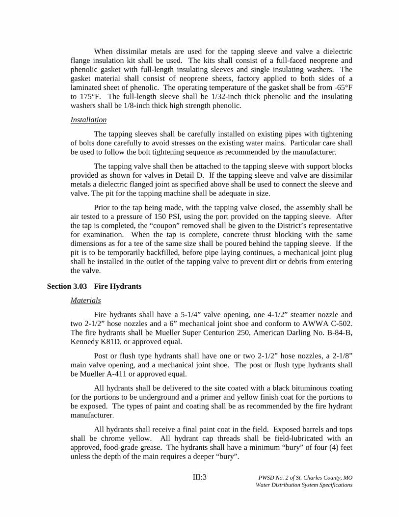
When dissimilar metals are used for the tapping sleeve and valve a dielectric flange insulation kit shall be used. The kits shall consist of a full-faced neoprene and phenolic gasket with full-length insulating sleeves and single insulating washers. The gasket material shall consist of neoprene sheets, factory applied to both sides of a laminated sheet of phenolic. The operating temperature of the gasket shall be from -65°F to 175°F. The full-length sleeve shall be 1/32-inch thick phenolic and the insulating washers shall be 1/8-inch thick high strength phenolic.
The tapping sleeves shall be carefully installed on existing pipes with tightening of bolts done carefully to avoid stresses on the existing water mains. Particular care shall be used to follow the bolt tightening sequence as recommended by the manufacturer.
Installation
The tapping valve shall then be attached to the tapping sleeve with support blocks provided as shown for valves in Detail D. If the tapping sleeve and valve are dissimilar metals a dielectric flanged joint as specified above shall be used to connect the sleeve and valve. The pit for the tapping machine shall be adequate in size.
Prior to the tap being made, with the tapping valve closed, the assembly shall be air tested to a pressure of 150 PSI, using the port provided on the tapping sleeve. After the tap is completed, the “coupon” removed shall be given to the District’s representative for examination. When the tap is complete, concrete thrust blocking with the same dimensions as for a tee of the same size shall be poured behind the tapping sleeve. If the pit is to be temporarily backfilled, before pipe laying continues, a mechanical joint plug shall be installed in the outlet of the tapping valve to prevent dirt or debris from entering the valve.
Section 3.03 Fire Hydrants
Fire hydrants shall have a 5-1/4” valve opening, one 4-1/2” steamer nozzle and two 2-1/2” hose nozzles and a 6” mechanical joint shoe and conform to AWWA C-502. The fire hydrants shall be Mueller Super Centurion 250, American Darling No. B-84-B, Kennedy K81D, or approved equal.
Materials
Post or flush type hydrants shall have one or two 2-1/2” hose nozzles, a 2-1/8” main valve opening, and a mechanical joint shoe. The post or flush type hydrants shall be Mueller A-411 or approved equal.
All hydrants shall be delivered to the site coated with a black bituminous coating for the portions to be underground and a primer and yellow finish coat for the portions to be exposed. The types of paint and coating shall be as recommended by the fire hydrant manufacturer.
All hydrants shall receive a final paint coat in the field. Exposed barrels and tops shall be chrome yellow. All hydrant cap threads shall be field-lubricated with an approved, food-grade grease. The hydrants shall have a minimum “bury” of four (4) feet unless the depth of the main requires a deeper “bury”.

III:4 PWSD No. 2 of St. Charles County, MO Water Distribution System Specifications
Refer to Detail B of these specifications.
Fire hydrants shall be installed where shown on the plans and as shown on Detail B of these Specifications. Care shall be taken to set the hydrant plumb and the 4-1/2” pumper nozzle shall face the street. Care shall also be exercised to set the fire hydrants to meet the final finished grade as indicated by the “height” given on the stake for the hydrant. After installation and backfill, the exposed barrel and top shall be given a finish coat of “Chrome yellow” paint. The operating nuts on the top of fire hydrant shall not be painted.
Installation
In general, fire hydrants will not require thrust blocks when they are restrained by “Anchor Loks” or “Megalug” follower glands as shown on Detail B of these specifications. However, if they are installed at a dead end, a thrust block, same as for a 6” x 6” tee shall be provided to restrain the fire hydrant and care shall be taken not to encase the drain hole in the fire hydrant.
Section 3.04 Air Release Devices
For high points of water mains, air release valves shall be provided and such valves shall be Combination Air Valves for Waterworks Service in accordance with AWWA C512. The valves shall be in concrete vaults, 72” in diameter, with cover, air vent, isolation valve and pressure gauges as approved by the District Engineer. Combination Air Valves shall be A.R.I. Model D-040-C, Combination Air Valve (Barak) or approved equal.
Materials
Where there are pronounced high spots in water mains 8” and smaller, fire hydrants shall be located at said high spots. For high spots in water mains larger than 8”, automatic air release valves shall be provided as specified hereinbefore. All automatic air release devices are to be permanent and constructed per Detail G.
Installation
(The remainder of this page intentionally left blank)

IV:1 PWSD No. 2 of St. Charles County, MO Water Distribution System Specifications
Article IV.
Section 4.01 Disinfection
TESTING
Disinfection shall be accomplished by placing sufficient hypochlorite granules (HTH) in each section of pipe or injection of a hypochlorite solution to achieve a chlorine residual in the pipeline, upon initial filling, of 50 mg/L (PPM). HTH tablets will not be allowed.
Following completion of the pipeline, it shall be slowly filled with water and a sample will be taken immediately and the chlorine residual must be 50 mg/L or greater. The solution shall be allowed to stand for 24 hours and a sample shall then be taken. The chlorine residual after 24 hours shall be 10 mg/L or greater. If the piping shows insufficient chlorine residuals in either test, the piping shall be re-chlorinated by the injection of a hypochlorite solution until satisfactory results are achieved.
All disinfection shall be completed by the Contractor. Only the testing to determine the chlorine residual shall be completed by the District.
Section 4.02 Pressure Testing
Immediately following disinfection, the piping shall be pumped to a pressure (at the highest point in the project) of 150 PSI or higher where the working pressure is higher than 150 PSI as determined by the District.
In such cases, the test pressure shall be 50 psi greater than the working pressure and two pressure tests shall be conducted. The first test shall be with the fire hydrant auxiliary valves open and be to 150 PSI. The second test shall be with the fire hydrant auxiliary valves closed and be to the higher pressure as directed by the District.
All pumping equipment and pressure gauges shall be provided by the contractor. After achieving the test pressure, the piping shall be left closed for a period of two (2) hours. At the end of this time the pressure drop shall not exceed 2 PSI.
In addition, if the pressure appears, in the judgment of the District’s representative, to be continuing to drop, the test shall be continued for another two (2) hours and if any further drops occur, the test shall be considered a failure. If the pressure test fails, the contractor will be required to find and correct the source of the leakage. If this requires draining of the pipeline, when the leakage is corrected, the piping must be re-disinfected and the pressure tested again until satisfactory results are achieved.
De-chlorination will be performed by the Contractor prior to any chlorinated waters being released into the environment. Complete de-chlorination must be achieved.
Section 4.03 Leakage Testing
Testing for leakage shall be performed on all water mains. At the completion of the pressure test, the water main shall be re-pressurized to the test pressure by pumping potable water into the main. The volume of water required to re-pressurize the main shall

IV:2 PWSD No. 2 of St. Charles County, MO Water Distribution System Specifications
be measured. All mains shall meet leakage standards per AWWA C600. The maximum allowable leakage rate shall be calculated using the following equation:
L = SD(P)0.5÷148,000
Where: L = allowable leakage, in gallons per hour. S = length of pipe in test section, in feet. D = pipe diameter, in inches. P = average test pressure, psig.
If the volume of water put back into the main exceeds the maximum allowable leakage, as calculated by the equation above, the Contractor will be required to find and correct the source of the leakage. If this requires draining of the pipeline, when the leakage is corrected, the piping must be re-disinfected and the leakage test shall be performed again until satisfactory results are achieved. The testing requirements for pressure and duration shall be the same as those for the pressure test.
De-chlorination will be performed by the Contractor prior to any chlorinated waters being released into the environment. Complete de-chlorination must be achieved.
Section 4.04 Flushing
After satisfactory disinfection is achieved, all piping shall be thoroughly flushed until all water discharged is visibly clear. A final chlorine residual test will then be taken and the chlorine residual must be between 0.5 - 2.5 mg/L. If the residual is too high, additional flushing shall be done until the desired residual is obtained. If the residual is too low, the entire disinfection and flushing procedure shall be repeated until the desired results are achieved. Complete de-chlorination of discharged water shall be performed by the Contractor.
Section 4.05 Bacteriological Testing
After satisfactory disinfection and pressure testing, a sample shall be taken by the Contractor in the presence of a District representative and submitted to a laboratory approved by the MoDNR and the District for bacteriological analysis. After 24 hours, a second sample shall be taken in a like manner and submitted for analysis. The two samples must be found to be “safe” by the testing laboratory, and copies of the test results must be supplied to the District. If the samples are not found to be “safe” further flushing and /or disinfection as directed by the District shall be conducted by the Contractor until “safe” samples on two consecutive days are achieved. Following successful bacteriological testing and a determination by the District that the samples are “safe”, the mains may be placed into service.
If mains are not placed into service within 90 days samples must be retaken.

IV:3 PWSD No. 2 of St. Charles County, MO Water Distribution System Specifications
Section 4.06 Final Inspection and Tracer Wire Testing
After all work is completed and all disinfection, pressure testing, flushing and bacteriological testing is complete, the Contractor shall conduct a locater wire test between all sections of the wire in the presence of a District representative. If the test is satisfactory, all splices in valve boxes shall be made permanent by means of 3-M splice kits or approved equal. If the tests fail in a section, the Contractor must find and repair any failure in the locator wires.
A final inspection shall be made by a District representative and all valves and hydrants shall be plumb and be to proper grade and all cleanup work must be satisfactorily completed. The work shall be accepted only after completion of the final inspection. Any defects found in the final inspection shall be promptly corrected by the Contractor.
(The remainder of this page intentionally left blank)

A:1 PWSD No. 2 of St. Charles County, MO Water Distribution System Specifications
All Construction shall conform to the following taken from the “Design Guide for Community Water Systems” (effective August 29, 2003) as published by the MoDNR and as partially reproduced below. As MoDNR’s requirements change in the future, the latest edition of their rules will apply.
APPENDIX A
8.6. Separation of Water Mains, Sanitary Sewers and Combined Sewers
8.6.1. General.
The following factors should be considered in providing adequate separation:
a. Materials and type of joints for water and sewer pipes;
b. Soil conditions;
c. Service and branch connections into the water main and sewer line;
d. Compensating variations in the horizontal and vertical separations;
e. Space for repair and alterations of water and sewer pipes; and
f. Off-setting of water mains around manholes.
8.6.2. Parallel installation.
Water mains shall be laid at least ten feet horizontally from any existing or proposed sewer. The distance shall be measured edge to edge. In cases where it is not practical to maintain a ten-foot separation, the department may allow deviation on a case-by-case basis, if supported by data from the design engineer. Such deviation may allow installation of the water main closer to a sewer, provided that the water main is laid in a separate trench or on an undisturbed earth shelf located on one side of the sewer and on either case, at such an elevation that the bottom of the water main is at least 18 inches above the top of the sewer. In areas where the recommended separations cannot be obtained, either the waterline or the sewer line shall be constructed of mechanical joint pipe or cased in a continuous casing.
8.6.3. Crossings.
Water mains crossing sewers shall be laid to provide a minimum vertical clear distance of 18 inches between the outside of the water main and the outside of the sewer. This shall be the case where the water main is either above or below the sewer. At crossings, the full length of water pipe shall be located so both joints will be as far from the sewer as possible but in no case less than ten feet. Special structural support for the water and sewer pipes may be required. In areas where the recommended separations cannot be obtained either the waterline or the sewer line shall be constructed of mechanical joint pipe or cased in a continuous casing that extends no less than ten feet on both sides of the crossing.

A:2 PWSD No. 2 of St. Charles County, MO Water Distribution System Specifications
8.6.4. Exception.
Any variance from the specified separation distances in paragraphs 8.6.2.and 8.6.3. must be submitted to the department for approval.
8.6.5. Force mains.
There shall be at least a ten-foot horizontal separation between water mains and sanitary sewer force mains and they shall be in separate trenches. In areas where these separations cannot be obtained, either the waterline or the sewer line shall be cased in a continuous casing.
8.6.6. Sewer manholes.
No waterline shall be located closer than ten feet to any part of a sanitary or combined sewer manhole.
8.6.7. Disposal facilities.
No waterline shall be located closer than 25 feet to any on-site wastewater disposal facility, agricultural waste disposal facility, or landfill.
(The remainder of this page intentionally left blank)

B:1 PWSD No. 2 of St. Charles County, MO Water Distribution System Specifications
All Construction shall conform to the following taken from the “Design Guide for Community Water Systems” (effective August 29, 2003) as published by the Missouri Department of Natural Resources and as partially reproduced below. As MDNR’s requirements change in the future, the latest edition of their rules will apply.
APPENDIX B
8.7. Surface Water Crossings. Surface water crossings, whether over or under water, present special problems.
The department should be consulted before final plans are prepared. Positive joints shall be required in waterways and wet weather streams.
8.7.1. Above-water crossings.
The pipe shall be adequately supported and anchored, protected from damage and freezing and accessible for repair or replacement.
8.7.2. Underwater crossings.
a. Flowing streams.
A minimum cover of four feet shall be provided over the pipe. When crossing water courses are greater than 15 feet in width, the following shall be provided:
1. The pipe shall be of special construction, having flexible watertight joints. Steel or ductile iron ball-joint river pipe shall be used for open cut crossings. Restrained joint pipe may be used for open cut crossings, provided it is encased in a welded steel casing. Restrained joint pipe shall be used for bored crossings.
2. Valves shall be provided at both ends of water crossings so that the section can be isolated for testing or repair; the valves shall be easily accessible and should not be subject to flooding.
3. Permanent taps shall be provided on each side of the valve with a small meter to determine leakage and for sampling purposes.
4. The stream crossing pipe or casing shall extend at least 15 feet beyond the upper edge of the stream channel on each side of the stream.
b. Intermittent flowing streams.
1. Restrained joint pipe shall be used for all stream crossings.
2. The pipe shall extend at least 15 feet beyond the upper edge of the stream channel on each side of the stream.


PIPE
DIA.
A B C H C H C H C H C H
4 14 4 24 12 26 15 18 12 12 12 12 12
6 16 6 36 18 36 24 30 18 24 12 12 12
8 20 8 36 30 42 36 36 24 24 18 18 12
10 20 10 48 36 66 36 36 36 28 24 18 18
12 24 12 68 36 82 42 52 36 40 24 28 18
45
DEGREE
BEND
22-1/2
BEND
11-1/4
BEND
THRUST BLOCK DIMENSIONS - INCHES
ALL
FTGS.
TEE
PLUG
TAPPING
90
DEGREE
BEND


PIPE DIA. "D" WIDTH "W" HEIGHT "H" THICKNESS "T"
4 12 12 12
6 24 24 12
8 24 24 12
10 30 30 16
12 36 36 18
CROSS BLOCK DIMENSIONS


Recommended