VirtualChassis FeatureGuide forEX9200Switches
Modified: 2019-02-05
Copyright © 2019, Juniper Networks, Inc.

Juniper Networks, Inc.1133 InnovationWaySunnyvale, California 94089USA408-745-2000www.juniper.net
Juniper Networks, the Juniper Networks logo, Juniper, and Junos are registered trademarks of Juniper Networks, Inc. in the United Statesand other countries. All other trademarks, service marks, registeredmarks, or registered service marks are the property of their respectiveowners.
Juniper Networks assumes no responsibility for any inaccuracies in this document. Juniper Networks reserves the right to change, modify,transfer, or otherwise revise this publication without notice.
Virtual Chassis Feature Guide for EX9200 SwitchesCopyright © 2019 Juniper Networks, Inc. All rights reserved.
The information in this document is current as of the date on the title page.
YEAR 2000 NOTICE
Juniper Networks hardware and software products are Year 2000 compliant. Junos OS has no known time-related limitations through theyear 2038. However, the NTP application is known to have some difficulty in the year 2036.
ENDUSER LICENSE AGREEMENT
The Juniper Networks product that is the subject of this technical documentation consists of (or is intended for use with) Juniper Networkssoftware. Use of such software is subject to the terms and conditions of the End User License Agreement (“EULA”) posted athttps://support.juniper.net/support/eula/. By downloading, installing or using such software, you agree to the terms and conditions ofthat EULA.
Copyright © 2019, Juniper Networks, Inc.ii
Table of Contents
About the Documentation . . . . . . . . . . . . . . . . . . . . . . . . . . . . . . . . . . . . . . . . . . . . ix
Documentation and Release Notes . . . . . . . . . . . . . . . . . . . . . . . . . . . . . . . . . . ix
Using the Examples in This Manual . . . . . . . . . . . . . . . . . . . . . . . . . . . . . . . . . . ix
Merging a Full Example . . . . . . . . . . . . . . . . . . . . . . . . . . . . . . . . . . . . . . . . x
Merging a Snippet . . . . . . . . . . . . . . . . . . . . . . . . . . . . . . . . . . . . . . . . . . . . x
Documentation Conventions . . . . . . . . . . . . . . . . . . . . . . . . . . . . . . . . . . . . . . . xi
Documentation Feedback . . . . . . . . . . . . . . . . . . . . . . . . . . . . . . . . . . . . . . . . xiii
Requesting Technical Support . . . . . . . . . . . . . . . . . . . . . . . . . . . . . . . . . . . . . xiii
Self-Help Online Tools and Resources . . . . . . . . . . . . . . . . . . . . . . . . . . . xiv
Creating a Service Request with JTAC . . . . . . . . . . . . . . . . . . . . . . . . . . . xiv
Chapter 1 Virtual Chassis Overview . . . . . . . . . . . . . . . . . . . . . . . . . . . . . . . . . . . . . . . . . . . 15
Understanding EX9200 Virtual Chassis . . . . . . . . . . . . . . . . . . . . . . . . . . . . . . . . . . 15
Understanding Virtual Chassis Components . . . . . . . . . . . . . . . . . . . . . . . . . . . . . . 16
Maximum Switch Support . . . . . . . . . . . . . . . . . . . . . . . . . . . . . . . . . . . . . . . . . 17
Maximum Number of Switches in an EX Series Virtual Chassis . . . . . . . . 17
Maximum Switch Support in a QFX Series Virtual Chassis (Including
Mixed Virtual Chassis with EX Series Switches) . . . . . . . . . . . . . . . . 19
Virtual Chassis Ports (VCPs) . . . . . . . . . . . . . . . . . . . . . . . . . . . . . . . . . . . . . . 20
Virtual Chassis Port Options . . . . . . . . . . . . . . . . . . . . . . . . . . . . . . . . . . . 20
Automatic Virtual Chassis Port (VCP) Conversion . . . . . . . . . . . . . . . . . . 22
Virtual Chassis Port Link Aggregation Groups . . . . . . . . . . . . . . . . . . . . . 23
Master Routing Engine Role . . . . . . . . . . . . . . . . . . . . . . . . . . . . . . . . . . . . . . . 23
Backup Routing Engine Role . . . . . . . . . . . . . . . . . . . . . . . . . . . . . . . . . . . . . . . 24
Linecard Role . . . . . . . . . . . . . . . . . . . . . . . . . . . . . . . . . . . . . . . . . . . . . . . . . . . 25
Member Switch and Member ID . . . . . . . . . . . . . . . . . . . . . . . . . . . . . . . . . . . . 26
Mastership Priority . . . . . . . . . . . . . . . . . . . . . . . . . . . . . . . . . . . . . . . . . . . . . . 26
Virtual Chassis Identifier (VCID) . . . . . . . . . . . . . . . . . . . . . . . . . . . . . . . . . . . . 27
Nonvolatile Storage in a Virtual Chassis . . . . . . . . . . . . . . . . . . . . . . . . . . . . . . 27
Part 1 Configuring a Virtual Chassis
Chapter 2 Accessing and Configuring a Virtual Chassis and Managing Files . . . . . . . . 33
Accessing the Virtual Chassis Through the Management Interface . . . . . . . . . . . 34
Managing Files on Virtual Chassis Member Routers or Switches . . . . . . . . . . . . . . 35
Virtual Chassis Slot Number Mapping for Use with SNMP . . . . . . . . . . . . . . . . . . 36
Configuring an EX9200 Virtual Chassis . . . . . . . . . . . . . . . . . . . . . . . . . . . . . . . . . 38
Creating Configuration Groups for an EX9200 Virtual Chassis . . . . . . . . . . . . 38
Configuring the EX9200 Virtual Chassis . . . . . . . . . . . . . . . . . . . . . . . . . . . . . 39
Creating and Applying Configuration Groups for a Virtual Chassis . . . . . . . . . . . . 43
iiiCopyright © 2019, Juniper Networks, Inc.
Chapter 3 Virtual Chassis Ports . . . . . . . . . . . . . . . . . . . . . . . . . . . . . . . . . . . . . . . . . . . . . . 47
Configuring Virtual Chassis Ports to Interconnect Member Routers or
Switches . . . . . . . . . . . . . . . . . . . . . . . . . . . . . . . . . . . . . . . . . . . . . . . . . . . . . . 48
Deleting Virtual Chassis Ports in a Virtual Chassis Configuration . . . . . . . . . . . . . . 51
Verifying the Operation of Virtual Chassis Ports . . . . . . . . . . . . . . . . . . . . . . . . . . . 52
Chapter 4 Upgrading Junos OS in a Virtual Chassis . . . . . . . . . . . . . . . . . . . . . . . . . . . . . 55
Upgrading Junos OS Software in an EX9200 Virtual Chassis . . . . . . . . . . . . . . . . 55
Chapter 5 Deleting a Member ID . . . . . . . . . . . . . . . . . . . . . . . . . . . . . . . . . . . . . . . . . . . . . . 59
Deleting Member IDs in a Virtual Chassis Configuration . . . . . . . . . . . . . . . . . . . . 59
Chapter 6 Module Redundancy and GRES . . . . . . . . . . . . . . . . . . . . . . . . . . . . . . . . . . . . . 61
Targeted Traffic Distribution on Aggregated Ethernet Interfaces in a Virtual
Chassis . . . . . . . . . . . . . . . . . . . . . . . . . . . . . . . . . . . . . . . . . . . . . . . . . . . . . . . . 61
Targeted Distribution in a Virtual Chassis . . . . . . . . . . . . . . . . . . . . . . . . . . . . . 61
Benefits of Targeted Distribution . . . . . . . . . . . . . . . . . . . . . . . . . . . . . . . . . . . 62
Configuring Module Redundancy for a Virtual Chassis . . . . . . . . . . . . . . . . . . . . . . 62
Determining GRES Readiness in a Virtual Chassis Configuration . . . . . . . . . . . . . 64
Chapter 7 Global Roles and Local Roles that DetermineMastership andSwitchoverBehavior . . . . . . . . . . . . . . . . . . . . . . . . . . . . . . . . . . . . . . . . . . . . . . . . . . . . . . . . . 67
Mastership Election in a Virtual Chassis . . . . . . . . . . . . . . . . . . . . . . . . . . . . . . . . . 67
Global Roles and Local Roles in a Virtual Chassis . . . . . . . . . . . . . . . . . . . . . . . . . 69
Role Name Format . . . . . . . . . . . . . . . . . . . . . . . . . . . . . . . . . . . . . . . . . . . . . . 69
Global Role and Local Role Descriptions . . . . . . . . . . . . . . . . . . . . . . . . . . . . . 70
Switching the Global Master and Backup Roles in a Virtual Chassis
Configuration . . . . . . . . . . . . . . . . . . . . . . . . . . . . . . . . . . . . . . . . . . . . . . . . . . . 71
Chapter 8 Minimizing Network Disruption Using Split Detection . . . . . . . . . . . . . . . . . . 73
Split Detection Behavior in a Virtual Chassis . . . . . . . . . . . . . . . . . . . . . . . . . . . . . . 73
How Split Detection Works in a Virtual Chassis . . . . . . . . . . . . . . . . . . . . . . . . 73
Effect of Split Detection on Virtual Chassis Failure Scenarios . . . . . . . . . . . . 74
Disabling Split Detection in a Virtual Chassis Configuration . . . . . . . . . . . . . . . . . 78
Part 2 Troubleshooting
Chapter 9 Acquiring Troubleshooting Information . . . . . . . . . . . . . . . . . . . . . . . . . . . . . . 81
Configuring the Name of the Virtual Chassis Trace Log File . . . . . . . . . . . . . . . . . . 81
Configuring Characteristics of the Virtual Chassis Trace Log File . . . . . . . . . . . . . 82
Configuring Access to the Virtual Chassis Trace Log File . . . . . . . . . . . . . . . . . . . . 83
Using Regular Expressions to Refine theOutput of the Virtual Chassis Trace Log
File . . . . . . . . . . . . . . . . . . . . . . . . . . . . . . . . . . . . . . . . . . . . . . . . . . . . . . . . . . . 84
Configuring the Virtual Chassis Operations to Trace . . . . . . . . . . . . . . . . . . . . . . . 85
traceoptions (Virtual Chassis) . . . . . . . . . . . . . . . . . . . . . . . . . . . . . . . . . . . . . . . . . 87
Copyright © 2019, Juniper Networks, Inc.iv
Virtual Chassis Feature Guide for EX9200 Switches
Part 3 Routine Monitoring
Chapter 10 Monitoring a Virtual Chassis . . . . . . . . . . . . . . . . . . . . . . . . . . . . . . . . . . . . . . . . 93
Verifying the Status of Virtual Chassis Member Routers or Switches . . . . . . . . . . 93
Verifying Neighbor Reachability for Member Routers or Switches in a Virtual
Chassis . . . . . . . . . . . . . . . . . . . . . . . . . . . . . . . . . . . . . . . . . . . . . . . . . . . . . . . 93
Verifying Neighbor Reachability for Hardware Devices in a Virtual Chassis . . . . . 94
Viewing Information in the Virtual Chassis Control Protocol Adjacency
Database . . . . . . . . . . . . . . . . . . . . . . . . . . . . . . . . . . . . . . . . . . . . . . . . . . . . . . 95
Viewing Information in the Virtual Chassis Control Protocol Link-State
Database . . . . . . . . . . . . . . . . . . . . . . . . . . . . . . . . . . . . . . . . . . . . . . . . . . . . . . 95
Viewing Information About Virtual Chassis Port Interfaces in the Virtual Chassis
Control Protocol Database . . . . . . . . . . . . . . . . . . . . . . . . . . . . . . . . . . . . . . . . 96
Viewing Virtual Chassis Control Protocol Statistics for Member Devices and
Virtual Chassis Ports . . . . . . . . . . . . . . . . . . . . . . . . . . . . . . . . . . . . . . . . . . . . . 97
Part 4 Configuration Statements and Operational Commands
Chapter 11 Configuration Statements . . . . . . . . . . . . . . . . . . . . . . . . . . . . . . . . . . . . . . . . . 101
aggregated-ether-options . . . . . . . . . . . . . . . . . . . . . . . . . . . . . . . . . . . . . . . . . . . 102
logical-interface-fpc-redundancy (Aggregated Ethernet Subscriber
Interfaces) . . . . . . . . . . . . . . . . . . . . . . . . . . . . . . . . . . . . . . . . . . . . . . . . . . . . 105
member . . . . . . . . . . . . . . . . . . . . . . . . . . . . . . . . . . . . . . . . . . . . . . . . . . . . . . . . . 106
no-split-detection . . . . . . . . . . . . . . . . . . . . . . . . . . . . . . . . . . . . . . . . . . . . . . . . . . 107
preprovisioned . . . . . . . . . . . . . . . . . . . . . . . . . . . . . . . . . . . . . . . . . . . . . . . . . . . . 108
role . . . . . . . . . . . . . . . . . . . . . . . . . . . . . . . . . . . . . . . . . . . . . . . . . . . . . . . . . . . . . 109
serial-number . . . . . . . . . . . . . . . . . . . . . . . . . . . . . . . . . . . . . . . . . . . . . . . . . . . . . . 112
targeted-distribution (Static Interfaces over Aggregated Ethernet) . . . . . . . . . . . 113
traceoptions (Virtual Chassis) . . . . . . . . . . . . . . . . . . . . . . . . . . . . . . . . . . . . . . . . 114
virtual-chassis . . . . . . . . . . . . . . . . . . . . . . . . . . . . . . . . . . . . . . . . . . . . . . . . . . . . . 117
Chapter 12 Operational Commands: Administrative . . . . . . . . . . . . . . . . . . . . . . . . . . . . . 119
request virtual-chassis member-id delete (MX Series Virtual Chassis) . . . . . . . . 120
request virtual-chassis member-id set . . . . . . . . . . . . . . . . . . . . . . . . . . . . . . . . . . 121
request virtual-chassis routing-engine master switch . . . . . . . . . . . . . . . . . . . . . 123
request virtual-chassis vc-port . . . . . . . . . . . . . . . . . . . . . . . . . . . . . . . . . . . . . . . 126
Chapter 13 Operational Commands: Monitoring . . . . . . . . . . . . . . . . . . . . . . . . . . . . . . . . 129
show virtual-chassis active-topology . . . . . . . . . . . . . . . . . . . . . . . . . . . . . . . . . . 130
show virtual-chassis device-topology . . . . . . . . . . . . . . . . . . . . . . . . . . . . . . . . . . 135
show virtual-chassis protocol adjacency . . . . . . . . . . . . . . . . . . . . . . . . . . . . . . . . 142
show virtual-chassis protocol database . . . . . . . . . . . . . . . . . . . . . . . . . . . . . . . . 146
show virtual-chassis protocol interface . . . . . . . . . . . . . . . . . . . . . . . . . . . . . . . . . 150
show virtual-chassis protocol route . . . . . . . . . . . . . . . . . . . . . . . . . . . . . . . . . . . . 153
show virtual-chassis protocol statistics . . . . . . . . . . . . . . . . . . . . . . . . . . . . . . . . 156
show virtual-chassis . . . . . . . . . . . . . . . . . . . . . . . . . . . . . . . . . . . . . . . . . . . . . . . . 160
show virtual-chassis vc-port . . . . . . . . . . . . . . . . . . . . . . . . . . . . . . . . . . . . . . . . . 166
vCopyright © 2019, Juniper Networks, Inc.
Table of Contents

Copyright © 2019, Juniper Networks, Inc.vi
Virtual Chassis Feature Guide for EX9200 Switches
List of Tables
About the Documentation . . . . . . . . . . . . . . . . . . . . . . . . . . . . . . . . . . . . . . . . . . ix
Table 1: Notice Icons . . . . . . . . . . . . . . . . . . . . . . . . . . . . . . . . . . . . . . . . . . . . . . . . . . xi
Table 2: Text and Syntax Conventions . . . . . . . . . . . . . . . . . . . . . . . . . . . . . . . . . . . xii
Chapter 1 Virtual Chassis Overview . . . . . . . . . . . . . . . . . . . . . . . . . . . . . . . . . . . . . . . . . . . 15
Table 3: MaximumMember Switch Support for Virtual Chassis by Junos OS
Release . . . . . . . . . . . . . . . . . . . . . . . . . . . . . . . . . . . . . . . . . . . . . . . . . . . . . . . . 17
Table 4: VCP Options by Switch Type . . . . . . . . . . . . . . . . . . . . . . . . . . . . . . . . . . . 20
Part 1 Configuring a Virtual Chassis
Chapter 2 Accessing and Configuring a Virtual Chassis and Managing Files . . . . . . . . 33
Table 5: jnxFruSlot Numbers and Corresponding Slot Numbers in an MX Series
or EX9200 Virtual Chassis . . . . . . . . . . . . . . . . . . . . . . . . . . . . . . . . . . . . . . . . 37
Chapter 7 Global Roles and Local Roles that DetermineMastership andSwitchoverBehavior . . . . . . . . . . . . . . . . . . . . . . . . . . . . . . . . . . . . . . . . . . . . . . . . . . . . . . . . . 67
Table 6: Global Roles and Local Roles . . . . . . . . . . . . . . . . . . . . . . . . . . . . . . . . . . 70
Table 7: Virtual Chassis Global Role Transitions Before and After Mastership
Switchover . . . . . . . . . . . . . . . . . . . . . . . . . . . . . . . . . . . . . . . . . . . . . . . . . . . . . 72
Chapter 8 Minimizing Network Disruption Using Split Detection . . . . . . . . . . . . . . . . . . 73
Table 8: Effect of Split Detection on Common Virtual Chassis Failure
Scenarios . . . . . . . . . . . . . . . . . . . . . . . . . . . . . . . . . . . . . . . . . . . . . . . . . . . . . . 74
Part 2 Troubleshooting
Chapter 9 Acquiring Troubleshooting Information . . . . . . . . . . . . . . . . . . . . . . . . . . . . . . 81
Table 9: Tracing Flags for Virtual Chassis . . . . . . . . . . . . . . . . . . . . . . . . . . . . . . . . 85
Part 4 Configuration Statements and Operational Commands
Chapter 13 Operational Commands: Monitoring . . . . . . . . . . . . . . . . . . . . . . . . . . . . . . . . 129
Table 10: show virtual-chassis active-topology Output Fields . . . . . . . . . . . . . . . 130
Table 11: show virtual-chassis device-topology Output Fields . . . . . . . . . . . . . . . 135
Table 12: show virtual-chassis protocol adjacency Output Fields . . . . . . . . . . . . 143
Table 13: show virtual-chassis protocol database Output Fields . . . . . . . . . . . . . 147
Table 14: show virtual-chassis protocol interface Output Fields . . . . . . . . . . . . . . 151
Table 15: show virtual-chassis protocol route Output Fields . . . . . . . . . . . . . . . . 153
Table 16: show virtual-chassis protocol statistics Output Fields . . . . . . . . . . . . . 156
Table 17: show virtual-chassis Output Fields . . . . . . . . . . . . . . . . . . . . . . . . . . . . . 161
Table 18: show virtual-chassis vc-port Output Fields . . . . . . . . . . . . . . . . . . . . . . 166
viiCopyright © 2019, Juniper Networks, Inc.

Copyright © 2019, Juniper Networks, Inc.viii
Virtual Chassis Feature Guide for EX9200 Switches
About the Documentation
• Documentation and Release Notes on page ix
• Using the Examples in This Manual on page ix
• Documentation Conventions on page xi
• Documentation Feedback on page xiii
• Requesting Technical Support on page xiii
Documentation and Release Notes
To obtain the most current version of all Juniper Networks®technical documentation,
see the product documentation page on the Juniper Networks website at
https://www.juniper.net/documentation/.
If the information in the latest release notes differs from the information in the
documentation, follow the product Release Notes.
Juniper Networks Books publishes books by Juniper Networks engineers and subject
matter experts. These books go beyond the technical documentation to explore the
nuances of network architecture, deployment, and administration. The current list can
be viewed at https://www.juniper.net/books.
Using the Examples in This Manual
If you want to use the examples in this manual, you can use the loadmerge or the load
merge relative command. These commands cause the software to merge the incoming
configuration into the current candidate configuration. The example does not become
active until you commit the candidate configuration.
If the example configuration contains the top level of the hierarchy (or multiple
hierarchies), the example is a full example. In this case, use the loadmerge command.
If the example configuration does not start at the top level of the hierarchy, the example
is a snippet. In this case, use the loadmerge relative command. These procedures are
described in the following sections.
ixCopyright © 2019, Juniper Networks, Inc.
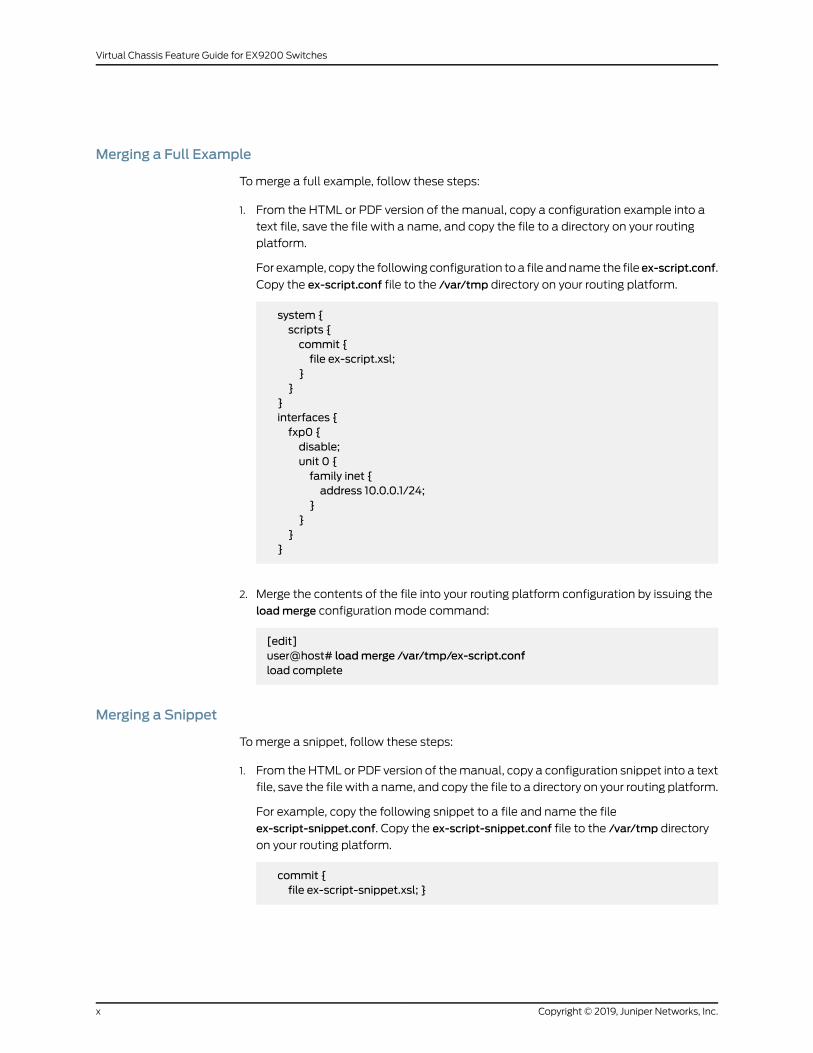
Merging a Full Example
Tomerge a full example, follow these steps:
1. From the HTML or PDF version of the manual, copy a configuration example into a
text file, save the file with a name, and copy the file to a directory on your routing
platform.
For example, copy the following configuration toa file andname the file ex-script.conf.
Copy the ex-script.conf file to the /var/tmp directory on your routing platform.
system {scripts {commit {file ex-script.xsl;
}}
}interfaces {fxp0 {disable;unit 0 {family inet {address 10.0.0.1/24;
}}
}}
2. Merge the contents of the file into your routing platform configuration by issuing the
loadmerge configuration mode command:
[edit]user@host# loadmerge /var/tmp/ex-script.confload complete
Merging a Snippet
Tomerge a snippet, follow these steps:
1. From the HTML or PDF version of themanual, copy a configuration snippet into a text
file, save the file with a name, and copy the file to a directory on your routing platform.
For example, copy the following snippet to a file and name the file
ex-script-snippet.conf. Copy the ex-script-snippet.conf file to the /var/tmp directory
on your routing platform.
commit {file ex-script-snippet.xsl; }
Copyright © 2019, Juniper Networks, Inc.x
Virtual Chassis Feature Guide for EX9200 Switches
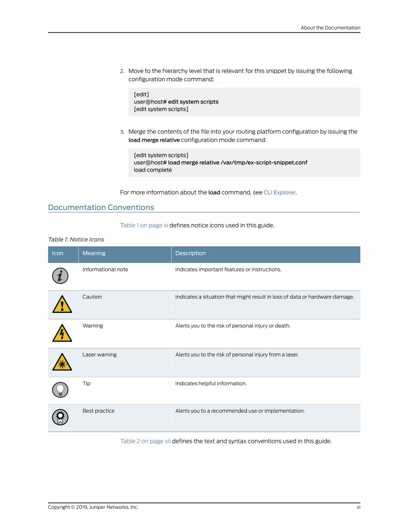
2. Move to the hierarchy level that is relevant for this snippet by issuing the following
configuration mode command:
[edit]user@host# edit system scripts[edit system scripts]
3. Merge the contents of the file into your routing platform configuration by issuing the
loadmerge relative configuration mode command:
[edit system scripts]user@host# loadmerge relative /var/tmp/ex-script-snippet.confload complete
For more information about the load command, see CLI Explorer.
Documentation Conventions
Table 1 on page xi defines notice icons used in this guide.
Table 1: Notice Icons
DescriptionMeaningIcon
Indicates important features or instructions.Informational note
Indicates a situation that might result in loss of data or hardware damage.Caution
Alerts you to the risk of personal injury or death.Warning
Alerts you to the risk of personal injury from a laser.Laser warning
Indicates helpful information.Tip
Alerts you to a recommended use or implementation.Best practice
Table 2 on page xii defines the text and syntax conventions used in this guide.
xiCopyright © 2019, Juniper Networks, Inc.
About the Documentation
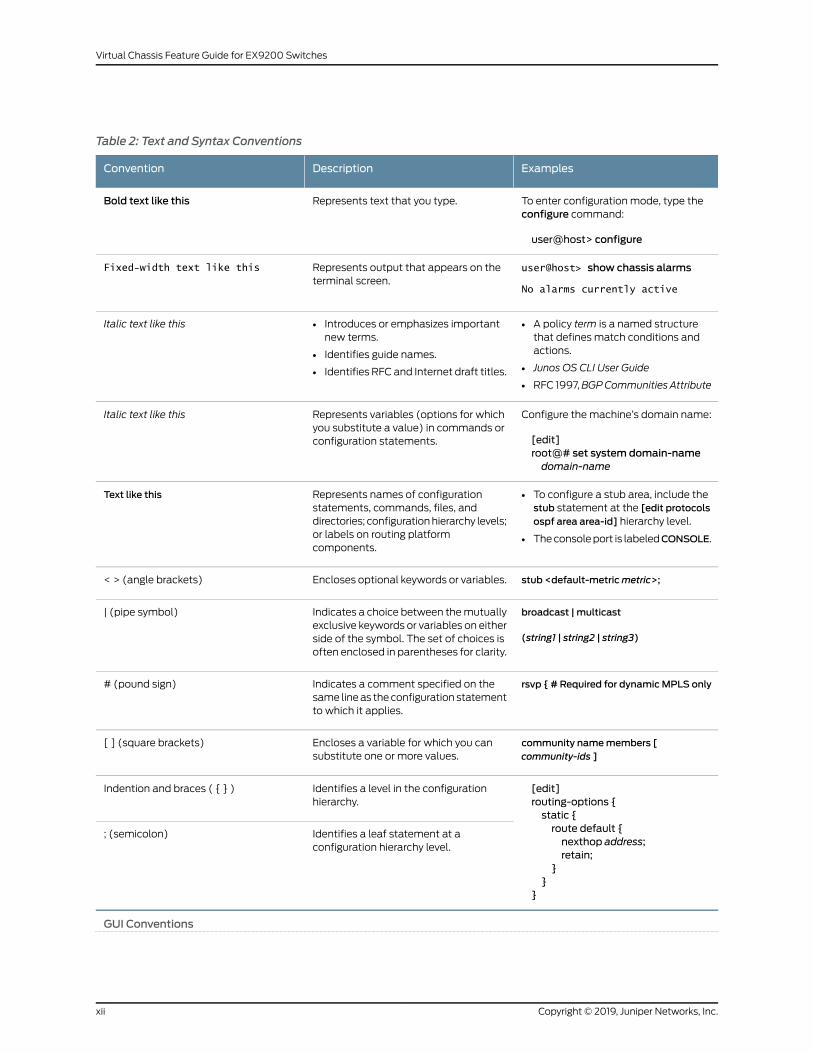
Table 2: Text and Syntax Conventions
ExamplesDescriptionConvention
To enter configuration mode, type theconfigure command:
user@host> configure
Represents text that you type.Bold text like this
user@host> show chassis alarms
No alarms currently active
Represents output that appears on theterminal screen.
Fixed-width text like this
• A policy term is a named structurethat defines match conditions andactions.
• Junos OS CLI User Guide
• RFC 1997,BGPCommunities Attribute
• Introduces or emphasizes importantnew terms.
• Identifies guide names.
• Identifies RFC and Internet draft titles.
Italic text like this
Configure themachine’s domain name:
[edit]root@# set system domain-namedomain-name
Represents variables (options for whichyou substitute a value) in commands orconfiguration statements.
Italic text like this
• To configure a stub area, include thestub statement at the [edit protocolsospf area area-id] hierarchy level.
• Theconsoleport is labeledCONSOLE.
Represents names of configurationstatements, commands, files, anddirectories; configurationhierarchy levels;or labels on routing platformcomponents.
Text like this
stub <default-metricmetric>;Encloses optional keywords or variables.< > (angle brackets)
broadcast | multicast
(string1 | string2 | string3)
Indicates a choice between themutuallyexclusive keywords or variables on eitherside of the symbol. The set of choices isoften enclosed in parentheses for clarity.
| (pipe symbol)
rsvp { # Required for dynamicMPLS onlyIndicates a comment specified on thesame lineas theconfiguration statementto which it applies.
# (pound sign)
community namemembers [community-ids ]
Encloses a variable for which you cansubstitute one or more values.
[ ] (square brackets)
[edit]routing-options {static {route default {nexthop address;retain;
}}
}
Identifies a level in the configurationhierarchy.
Indention and braces ( { } )
Identifies a leaf statement at aconfiguration hierarchy level.
; (semicolon)
GUI Conventions
Copyright © 2019, Juniper Networks, Inc.xii
Virtual Chassis Feature Guide for EX9200 Switches
Table 2: Text and Syntax Conventions (continued)
ExamplesDescriptionConvention
• In the Logical Interfaces box, selectAll Interfaces.
• To cancel the configuration, clickCancel.
Representsgraphicaluser interface(GUI)items you click or select.
Bold text like this
In the configuration editor hierarchy,select Protocols>Ospf.
Separates levels in a hierarchy of menuselections.
> (bold right angle bracket)
Documentation Feedback
We encourage you to provide feedback so that we can improve our documentation. You
can use either of the following methods:
• Online feedback system—Click TechLibrary Feedback, on the lower right of any page
on the Juniper Networks TechLibrary site, and do one of the following:
• Click the thumbs-up icon if the information on the page was helpful to you.
• Click the thumbs-down icon if the information on the page was not helpful to you
or if you have suggestions for improvement, and use the pop-up form to provide
feedback.
• E-mail—Sendyourcommentsto [email protected]. Includethedocument
or topic name, URL or page number, and software version (if applicable).
Requesting Technical Support
Technical product support is available through the JuniperNetworksTechnicalAssistance
Center (JTAC). If you are a customer with an active J-Care or Partner Support Service
support contract, or are covered under warranty, and need post-sales technical support,
you can access our tools and resources online or open a case with JTAC.
• JTAC policies—For a complete understanding of our JTAC procedures and policies,
review the JTAC User Guide located at
https://www.juniper.net/us/en/local/pdf/resource-guides/7100059-en.pdf.
• Product warranties—For product warranty information, visit
https://www.juniper.net/support/warranty/.
• JTAC hours of operation—The JTAC centers have resources available 24 hours a day,
7 days a week, 365 days a year.
xiiiCopyright © 2019, Juniper Networks, Inc.
About the Documentation
Self-Help Online Tools and Resources
For quick and easy problem resolution, Juniper Networks has designed an online
self-service portal called the Customer Support Center (CSC) that provides youwith the
following features:
• Find CSC offerings: https://www.juniper.net/customers/support/
• Search for known bugs: https://prsearch.juniper.net/
• Find product documentation: https://www.juniper.net/documentation/
• Find solutions and answer questions using our Knowledge Base: https://kb.juniper.net/
• Download the latest versions of software and review release notes:
https://www.juniper.net/customers/csc/software/
• Search technical bulletins for relevant hardware and software notifications:
https://kb.juniper.net/InfoCenter/
• Join and participate in the Juniper Networks Community Forum:
https://www.juniper.net/company/communities/
• Create a service request online: https://myjuniper.juniper.net
Toverify serviceentitlementbyproduct serial number, useourSerialNumberEntitlement
(SNE) Tool: https://entitlementsearch.juniper.net/entitlementsearch/
Creating a Service Request with JTAC
You can create a service request with JTAC on theWeb or by telephone.
• Visit https://myjuniper.juniper.net.
• Call 1-888-314-JTAC (1-888-314-5822 toll-free in the USA, Canada, and Mexico).
For international or direct-dial options in countries without toll-free numbers, see
https://support.juniper.net/support/requesting-support/.
Copyright © 2019, Juniper Networks, Inc.xiv
Virtual Chassis Feature Guide for EX9200 Switches
CHAPTER 1
Virtual Chassis Overview
• Understanding EX9200 Virtual Chassis on page 15
• Understanding Virtual Chassis Components on page 16
Understanding EX9200 Virtual Chassis
CAUTION: Wedonot recommendusingEX9200switches inaVirtualChassis,and support for that architecture was phased out as of Junos OS Release17.1R1. For deployments with EX9200 switches, we recommend planning ormoving to MC-LAG or Junos Fusion Enterprise architectures instead of usinga Virtual Chassis.
EX9200 Virtual Chassis brings the Virtual Chassis flexible, scaling switch solution to
Juniper Networks EX9200 Ethernet Switches. You can connect two EX9200 switches
into an EX9200 Virtual Chassis andmanage the interconnected switches as a single
chassis. The advantages of connecting multiple switches into a Virtual Chassis include
better-managedbandwidthatanetwork layer, simplifiedconfigurationandmaintenance
becausemultiple devices can bemanaged as a single device, increased fault tolerance
andhighavailability (HA)becauseaVirtualChassis can remainactiveandnetwork traffic
can be redirected to other member switches when a single member switch fails, and a
flatter, simplified Layer 2 network topology that minimizes or eliminates the need for
loop prevention protocols such as Spanning Tree Protocol (STP).
NOTE: Starting with Junos OS Release 17.1R1, EX9200 switches supportEX9200-RE2module. You cannot form a Virtual Chassis using an EX9200switchwithanEX9200-RE2module installed in it. If inadvertentlyconfiguredas a Virtual Chassis, the device will not start up properly; use the request
virtual-chassis member-id delete <force> command to remove the Virtual
Chassis setting.
You configure an EX9200 Virtual Chassis by configuring optical interfaces into Virtual
Chassis ports (VCPs). VCPs connect switches together to form a Virtual Chassis, and
are responsible for passing all data and control traffic betweenmember switches in the
Virtual Chassis.
15Copyright © 2019, Juniper Networks, Inc.
You can increase VCP bandwidth betweenmember switches by configuring multiple
interfaces between the same two switches into VCPs. Whenmultiple VCPs are
interconnecting the same twomember switches, a link aggregation group (LAG) bundle
is automatically formed when the VCPs are on interfaces supporting identical speeds.
For instance, if you have two 10-Gigabit SFP+ interfaces configured as VCPs between
member switches, a LAGwith twomember links with 20 Gbps of total bandwidth is
formed.
AnEX9200VirtualChassis canbecomposedofany twoEX9200switches.BothEX9200
switches must have dual Routing Engines installed, and all Routing Engines must be
running the sameversionof JunosOS.All combinations of EX9204, EX9208, andEX9214
switches can be interconnected to form a Virtual Chassis.
Release History Table DescriptionRelease
We do not recommend using EX9200 switches in a Virtual Chassis, andsupport for that architecturewas phased out as of JunosOSRelease 17.1R1.
17.1R1
RelatedDocumentation
Configuring an EX9200 Virtual Chassis on page 38•
Understanding Virtual Chassis Components
This topic describes the components of an EX series or a QFX Series Virtual Chassis.
• An EX Series Virtual Chassis is a supported combination of standalone EX Series
switches interconnected andmanaged as a single chassis. This topic applies to all EX
Series Virtual Chassis except EX8200 Virtual Chassis.
SeeUnderstandingEX8200VirtualChassisComponents for informationaboutEX8200
Virtual Chassis.
NOTE: Wedonot recommendusing EX9200switches in aVirtual Chassis,and support for that architecture was phased out as of Junos OS Release17.1R1. For deployments with EX9200 switches, we recommend planningor moving to MC-LAG or Junos Fusion Enterprise architectures instead ofusing a Virtual Chassis.
• A QFX Series Virtual Chassis is a supported combination of standalone QFX3500,
QFX3600, QFX5100, QFX5110, or QFX5200 switches interconnected andmanaged
asasinglechassis. EX4300switches (excludingmultigigabitmodels (EX4300-48MP))
can also be interconnected into amixedVirtual ChassiswithQFX3500,QFX3600, and
QFX5100 switches.
Copyright © 2019, Juniper Networks, Inc.16
Virtual Chassis Feature Guide for EX9200 Switches
This topicdoesnotdiscussVirtualChassis Fabric components. For informationonVirtual
Chassis Fabric components, see Understanding Virtual Chassis Fabric Components.
• Maximum Switch Support on page 17
• Virtual Chassis Ports (VCPs) on page 20
• Master Routing Engine Role on page 23
• Backup Routing Engine Role on page 24
• Linecard Role on page 25
• Member Switch and Member ID on page 26
• Mastership Priority on page 26
• Virtual Chassis Identifier (VCID) on page 27
• Nonvolatile Storage in a Virtual Chassis on page 27
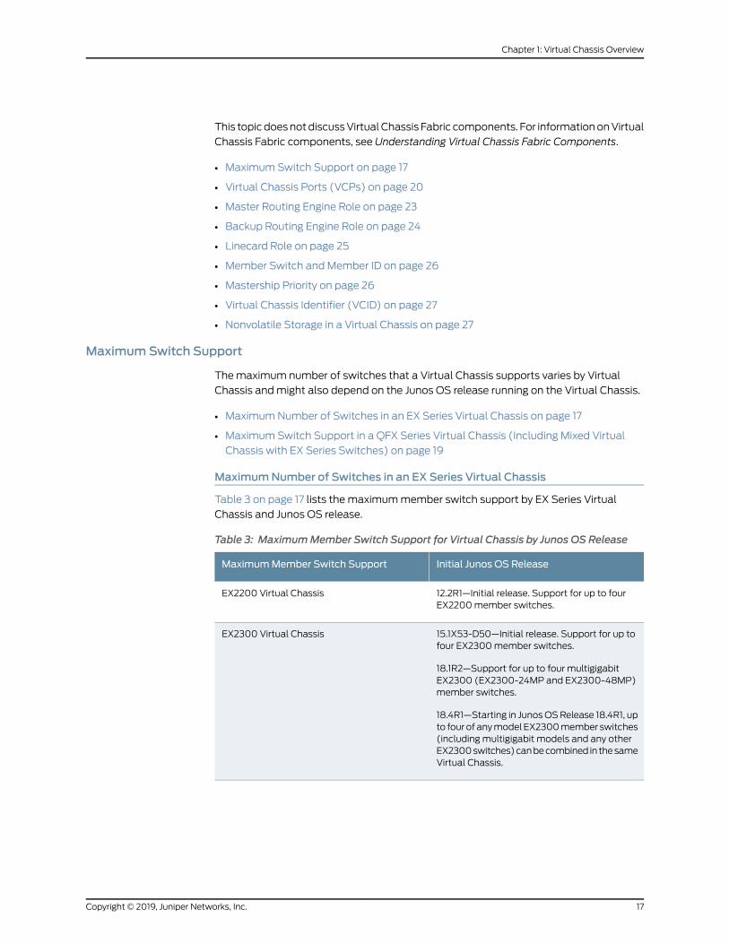
MaximumSwitch Support
Themaximum number of switches that a Virtual Chassis supports varies by Virtual
Chassis andmight also depend on the Junos OS release running on the Virtual Chassis.
• MaximumNumber of Switches in an EX Series Virtual Chassis on page 17
• Maximum Switch Support in a QFX Series Virtual Chassis (Including Mixed Virtual
Chassis with EX Series Switches) on page 19
MaximumNumber of Switches in an EX Series Virtual Chassis
Table 3 on page 17 lists the maximummember switch support by EX Series Virtual
Chassis and Junos OS release.
Table 3: MaximumMember Switch Support for Virtual Chassis by Junos OS Release
Initial Junos OS ReleaseMaximumMember Switch Support
12.2R1—Initial release. Support for up to fourEX2200member switches.
EX2200 Virtual Chassis
15.1X53-D50—Initial release. Support for up tofour EX2300member switches.
18.1R2—Support for up to four multigigabitEX2300 (EX2300-24MP and EX2300-48MP)member switches.
18.4R1—Starting in JunosOSRelease 18.4R1, upto fourof anymodelEX2300member switches(including multigigabit models and any otherEX2300switches)canbecombined in thesameVirtual Chassis.
EX2300 Virtual Chassis
17Copyright © 2019, Juniper Networks, Inc.
Chapter 1: Virtual Chassis Overview
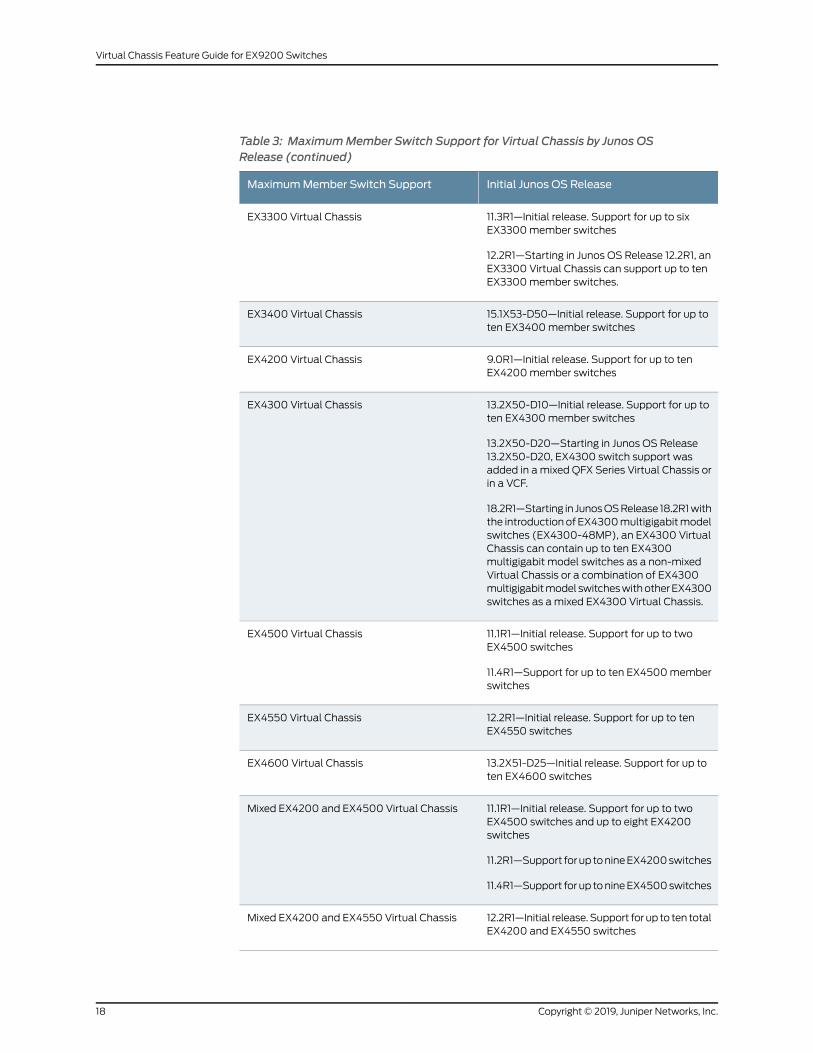
Table 3: MaximumMember Switch Support for Virtual Chassis by Junos OSRelease (continued)
Initial Junos OS ReleaseMaximumMember Switch Support
11.3R1—Initial release. Support for up to sixEX3300member switches
12.2R1—Starting in Junos OS Release 12.2R1, anEX3300 Virtual Chassis can support up to tenEX3300member switches.
EX3300 Virtual Chassis
15.1X53-D50—Initial release. Support for up toten EX3400member switches
EX3400 Virtual Chassis
9.0R1—Initial release. Support for up to tenEX4200member switches
EX4200 Virtual Chassis
13.2X50-D10—Initial release. Support for up toten EX4300member switches
13.2X50-D20—Starting in Junos OS Release13.2X50-D20, EX4300 switch support wasadded in a mixed QFX Series Virtual Chassis orin a VCF.
18.2R1—Starting in JunosOSRelease 18.2R1withthe introductionof EX4300multigigabitmodelswitches (EX4300-48MP), an EX4300 VirtualChassis can contain up to ten EX4300multigigabit model switches as a non-mixedVirtual Chassis or a combination of EX4300multigigabitmodel switcheswithotherEX4300switches as amixed EX4300 Virtual Chassis.
EX4300 Virtual Chassis
11.1R1—Initial release. Support for up to twoEX4500 switches
11.4R1—Support for up to ten EX4500memberswitches
EX4500 Virtual Chassis
12.2R1—Initial release. Support for up to tenEX4550 switches
EX4550 Virtual Chassis
13.2X51-D25—Initial release. Support for up toten EX4600 switches
EX4600 Virtual Chassis
11.1R1—Initial release. Support for up to twoEX4500 switches and up to eight EX4200switches
11.2R1—Support forup tonineEX4200switches
11.4R1—Support for up tonineEX4500switches
Mixed EX4200 and EX4500 Virtual Chassis
12.2R1—Initial release.Support for up to ten totalEX4200 and EX4550 switches
Mixed EX4200 and EX4550 Virtual Chassis
Copyright © 2019, Juniper Networks, Inc.18
Virtual Chassis Feature Guide for EX9200 Switches
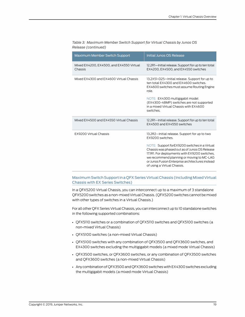
Table 3: MaximumMember Switch Support for Virtual Chassis by Junos OSRelease (continued)
Initial Junos OS ReleaseMaximumMember Switch Support
12.2R1—Initial release.Support for up to ten totalEX4200, EX4500, and EX4550 switches
Mixed EX4200, EX4500, and EX4550 VirtualChassis
13.2X51-D25—Initial release. Support for up toten total EX4300 and EX4600 switches.EX4600switchesmustassumeRoutingEnginerole.
NOTE: EX4300multigigabit model(EX4300-48MP) switches are not supportedin a mixed Virtual Chassis with EX4600switches.
Mixed EX4300 and EX4600 Virtual Chassis
12.2R1—Initial release.Support for up to ten totalEX4500 and EX4550 switches
Mixed EX4500 and EX4550 Virtual Chassis
13.2R2—Initial release. Support for up to twoEX9200 switches.
NOTE: Support forEX9200switches inaVirtualChassiswasphasedoutasof JunosOSRelease17.1R1. For deployments with EX9200 switches,we recommendplanning ormoving toMC-LAGor JunosFusionEnterprisearchitectures insteadof using a Virtual Chassis.
EX9200 Virtual Chassis
MaximumSwitchSupport inaQFXSeriesVirtualChassis (IncludingMixedVirtualChassis with EX Series Switches)
In a QFX5200 Virtual Chassis, you can interconnect up to amaximum of 3 standalone
QFX5200switchesasanon-mixedVirtualChassis. (QFX5200switchescannotbemixed
with other types of switches in a Virtual Chassis.)
Forall otherQFXSeriesVirtualChassis, youcan interconnectup to 10standaloneswitches
in the following supported combinations:
• QFX5110 switches or a combination of QFX5110 switches and QFX5100 switches (a
non-mixed Virtual Chassis)
• QFX5100 switches (a non-mixed Virtual Chassis)
• QFX5100 switches with any combination of QFX3500 and QFX3600 switches, and
EX4300 switches excluding the multigigabit models (a mixedmode Virtual Chassis)
• QFX3500 switches, or QFX3600 swtiches, or any combination of QFX3500 switches
and QFX3600 switches (a non-mixed Virtual Chassis)
• AnycombinationofQFX3500andQFX3600switcheswithEX4300switchesexcluding
the multigigabit models (a mixedmode Virtual Chassis)
19Copyright © 2019, Juniper Networks, Inc.
Chapter 1: Virtual Chassis Overview
NOTE: In JunosOS release 13.2X51-D20, you can interconnect only up to fourQFX5100-96S switches in a non-mixed QFX5100 Virtual Chassis. Startingin Junos OS release 13.2X51-D25, you can configure up to ten QFX5100-96Sswitches into amixed or non-mixed QFX5100 Virtual Chassis.
Virtual Chassis Ports (VCPs)
You set up a Virtual Chassis by configuring Virtual Chassis ports (VCPs) on themember
switches, and interconnecting the switches using the VCPs. VCPs are responsible for
passing all data and control traffic betweenmember switches in the Virtual Chassis.
• Virtual Chassis Port Options on page 20
• Automatic Virtual Chassis Port (VCP) Conversion on page 22
• Virtual Chassis Port Link Aggregation Groups on page 23
Virtual Chassis Port Options
Some switches have dedicated VCPs; these ports can only be used as VCPs and cannot
be reconfigured as network ports. Dedicated VCPs allow you to interconnect switches
without requiring any additional interface configuration.
Some switches have ports that are configured as VCPs by default. You do not need to
explicitly configure those as VCPs to use them to interconnect those switches into a
Virtual Chassis.
Most switches have optical or uplink ports that can also be configured as VCPs.
To interconnect switches that do not have dedicated or default-configured VCPs, or to
interconnect switches across greater distances than allowed by a dedicated VCP
connection, youmust configure the VCPs. Also, when adding switches to an existing
VirtualChassis, oraddingnewredundant linksbetweenexistingmembers, if theautomatic
VCP conversion feature is enabled, under the right conditions the ports on both sides of
the connection will convert into VCPs automatically (see “Automatic Virtual Chassis
Port (VCP) Conversion” on page 22).
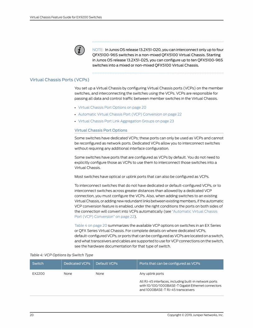
Table 4 on page 20 summarizes the available VCP options on switches in an EX Series
or QFX Series Virtual Chassis. For complete details on where dedicated VCPs,
default-configuredVCPs, or ports that canbeconfiguredasVCPsare locatedonaswitch,
andwhat transceiversandcablesare supported touse forVCPconnectionson theswitch,
see the hardware documentation for that type of switch.
Table 4: VCPOptions by Switch Type
Ports that can be configured as VCPsDefault VCPsDedicated VCPsSwitch
Any uplink ports
All RJ-45 interfaces, including built-in network portswith 10/100/1000BASE-TGigabit Ethernet connectorsand 1000BASE-T RJ-45 transceivers
NoneNoneEX2200
Copyright © 2019, Juniper Networks, Inc.20
Virtual Chassis Feature Guide for EX9200 Switches
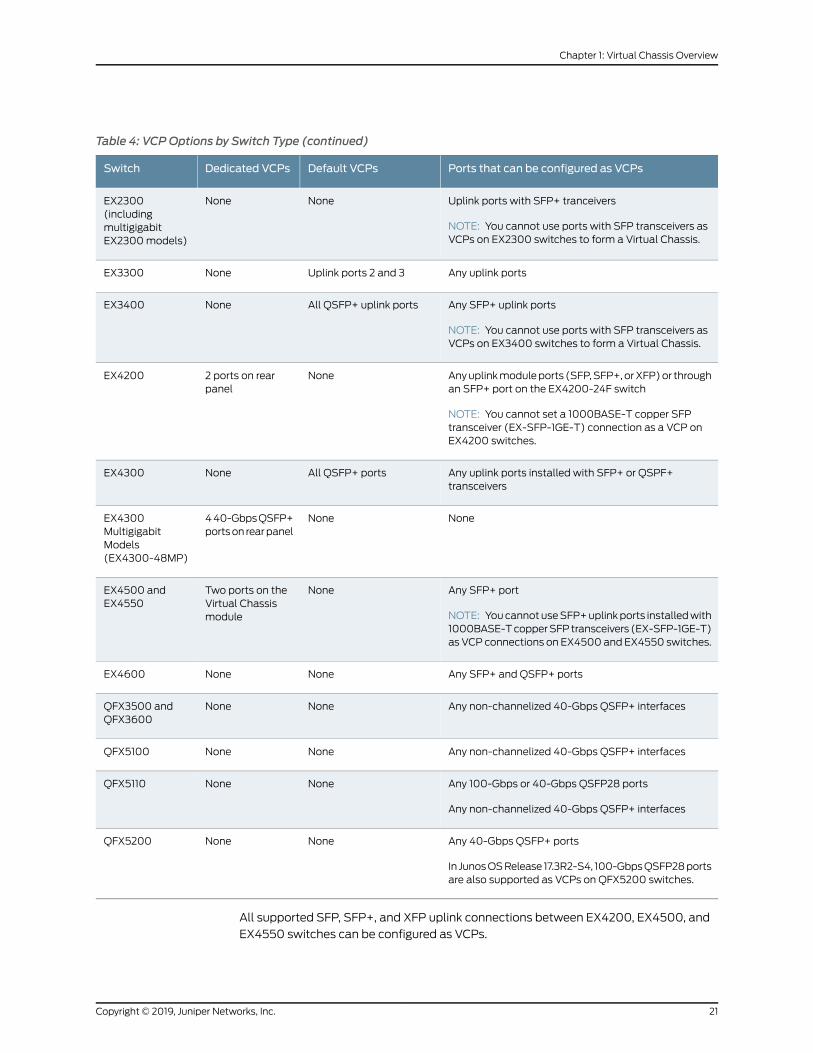
Table 4: VCPOptions by Switch Type (continued)
Ports that can be configured as VCPsDefault VCPsDedicated VCPsSwitch
Uplink ports with SFP+ tranceivers
NOTE: You cannot use ports with SFP transceivers asVCPs on EX2300 switches to form a Virtual Chassis.
NoneNoneEX2300(includingmultigigabitEX2300models)
Any uplink portsUplink ports 2 and 3NoneEX3300
Any SFP+ uplink ports
NOTE: You cannot use ports with SFP transceivers asVCPs on EX3400 switches to form a Virtual Chassis.
All QSFP+ uplink portsNoneEX3400
Anyuplinkmoduleports (SFP,SFP+,orXFP)or throughan SFP+ port on the EX4200-24F switch
NOTE: You cannot set a 1000BASE-T copper SFPtransceiver (EX-SFP-1GE-T) connection as a VCP onEX4200 switches.
None2 ports on rearpanel
EX4200
Any uplink ports installed with SFP+ or QSPF+transceivers
All QSFP+ portsNoneEX4300
NoneNone440-GbpsQSFP+portson rearpanel
EX4300MultigigabitModels(EX4300-48MP)
Any SFP+ port
NOTE: YoucannotuseSFP+uplinkports installedwith1000BASE-TcopperSFP transceivers (EX-SFP-1GE-T)as VCP connections on EX4500 and EX4550 switches.
NoneTwo ports on theVirtual Chassismodule
EX4500 andEX4550
Any SFP+ and QSFP+ portsNoneNoneEX4600
Any non-channelized 40-Gbps QSFP+ interfacesNoneNoneQFX3500 andQFX3600
Any non-channelized 40-Gbps QSFP+ interfacesNoneNoneQFX5100
Any 100-Gbps or 40-Gbps QSFP28 ports
Any non-channelized 40-Gbps QSFP+ interfaces
NoneNoneQFX5110
Any 40-Gbps QSFP+ ports
In JunosOSRelease 17.3R2-S4, 100-GbpsQSFP28portsare also supported as VCPs on QFX5200 switches.
NoneNoneQFX5200
All supported SFP, SFP+, and XFP uplink connections between EX4200, EX4500, and
EX4550 switches can be configured as VCPs.
21Copyright © 2019, Juniper Networks, Inc.
Chapter 1: Virtual Chassis Overview
QSFP+ interfaces that have been channelized into SFP+ interfaces using a breakout
cable cannot be configured into VCPs.
Automatic Virtual Chassis Port (VCP) Conversion
When the automatic VCP conversion feature is enabled and you cable a new link from
anewswitchbeingadded intoanexistingVirtualChassis, or adda redundant linkbetween
twomembers of a Virtual Chassis, ports that can be VCPs are automatically converted
into VCPs under the following conditions:
• Link Layer Discovery Protocol (LLDP) or LLDP-Media Endpoint Discovery (LLDP-MED)
is enabled on the interfaces for the members on both ends of the new link. The two
sides exchange LLDP packets to accomplish the port conversion.
• The Virtual Chassismust be preprovisionedwith the switches on both sides of the link
alreadyconfigured in themembers list of theVirtualChassis using the setvirtual-chassis
member command.
• The interfaces for theports onboth endsof the link are not already configuredasVCPs.
Both sides of the link must be in the same state to handshake and establish the VCP
link.
UsingautomaticVCPconversionwhenaddingaswitch toapreprovisionedVirtualChassis
is also referred to as autoprovisioning the newmember.
Ports thatareconfiguredasVCPsbydefault onaswitchor thatwerepreviously configured
into VCPsmust be converted back into network ports using the request virtual-chassis
vc-port delete command for the port to be eligible for automatic VCP conversion. A port
that has been automatically converted into a VCP is not automatically converted back
into a network port when you remove a switch fromaVirtual Chassis and disconnect the
link.
Automatic VCP conversion is enabled by default on all Virtual Chassis, except in the
following cases:
• Starting in Junos OS Releases 15.1R7 and 14.1X53-D47, in EX2200, EX3300, EX4200,
EX4500, andEX4550VirtualChassis, automaticVCPconversion is disabledbydefault.
If desired, you can enable the feature by configuring the auto-conversion statement at
the [edit virtual-chassis] hierarchy level on the Virtual Chassis.
CAUTION: WhenautomaticVCPconversion is enabled in aVirtual Chassiswith switches that have dedicated VCPs (EX4200, EX4500, or EX4550Virtual Chassis), if network or uplink ports are automatically convertedinto VCPs to create a redundant link with a dedicated VCP connectionbetween the same two Virtual Chassis members, youmust reboot theVirtual Chassis to avoid creating a traffic loop within the Virtual Chassis.(The same issue can occur even if the ports aremanually converted intoVCPs to create the redundant VCP link with a dedicated VCP link, so thereboot is required to avoid traffic looping in that case as well.)
Copyright © 2019, Juniper Networks, Inc.22
Virtual Chassis Feature Guide for EX9200 Switches
• Starting in JunosOSReleases 14.1X53-D47, 17.4R2, 18.1R3, 18.2R2, and 18.3R1 forEX4300,
EX4600, and QFX Series Virtual Chassis (which have the automatic VCP conversion
feature enabled by default), you can choose to disable the feature by configuring the
no-auto-conversion statementat the [edit virtual-chassis]hierarchy level on theVirtual
Chassis. To return to the default behavior to re-enable automatic VCP conversion,
delete the no-auto-conversion statement from the configuration.
Virtual Chassis Port Link Aggregation Groups
You can increase VCP bandwidth betweenmember switches by configuring multiple
interfaces between the same two switches into VCPs.Whenmultiple VCPs interconnect
the same twomember switches, a Link Aggregation Group (LAG) or bundle is
automatically formed when the VCPs are on interfaces supporting identical speeds. For
example, if you have two 40-Gbps QSFP+ interfaces configured as VCPs between
member switches, a LAGwith twomember links with 80-Gbps of total bandwidth is
formed. However, 10-Gigabit SFP+ and 40-Gbps QSFP+ interfaces configured as VCPs
will not becomemembers of the same LAG.
Within a Virtual Chassis, you can also configure network interfaces located on different
Virtual Chassis member switches to form a LAG, which provides load-balancing and
redundancy for network traffic forwarded by the Virtual Chassis. See Understanding
Virtual Chassis Port Link Aggregation for details on the difference between VCP LAGs and
network interface LAGs within a Virtual Chassis.
Master Routing Engine Role
In a Virtual Chassis, eachmember switch is assigned one of two roles: Routing Engine
role or linecard role, and for Routing Engine role, receives a further designation as the
master or backup Routing Engine.
Themember that functionsas themaster in theRoutingEngine role in theVirtualChassis:
• Manages the member switches.
• Runs Junos OS for the switches as amaster Routing Engine.
• Runs the chassis management processes and control protocols.
• Represents all the member switches interconnected within the Virtual Chassis
configuration. (Thehostnameandother properties that youassign to this switchduring
setup apply to all members of the Virtual Chassis configuration.)
In a preprovisioned configuration, one of the twomembers assigned as routing-engine
functions as the master member. The selection of which member assigned as
routing-engine functions as master and which as backup is determined by the software
based on themaster election algorithm. See Understanding How the Master in a Virtual
Chassis Is Elected.
In a configuration that is not preprovisioned, the selection of the master and backup is
determined by themastership priority value and secondary factors in themaster election
algorithm.
23Copyright © 2019, Juniper Networks, Inc.
Chapter 1: Virtual Chassis Overview
All switches that are not assigned themaster or backup Routing Engine role function in
the linecard role.
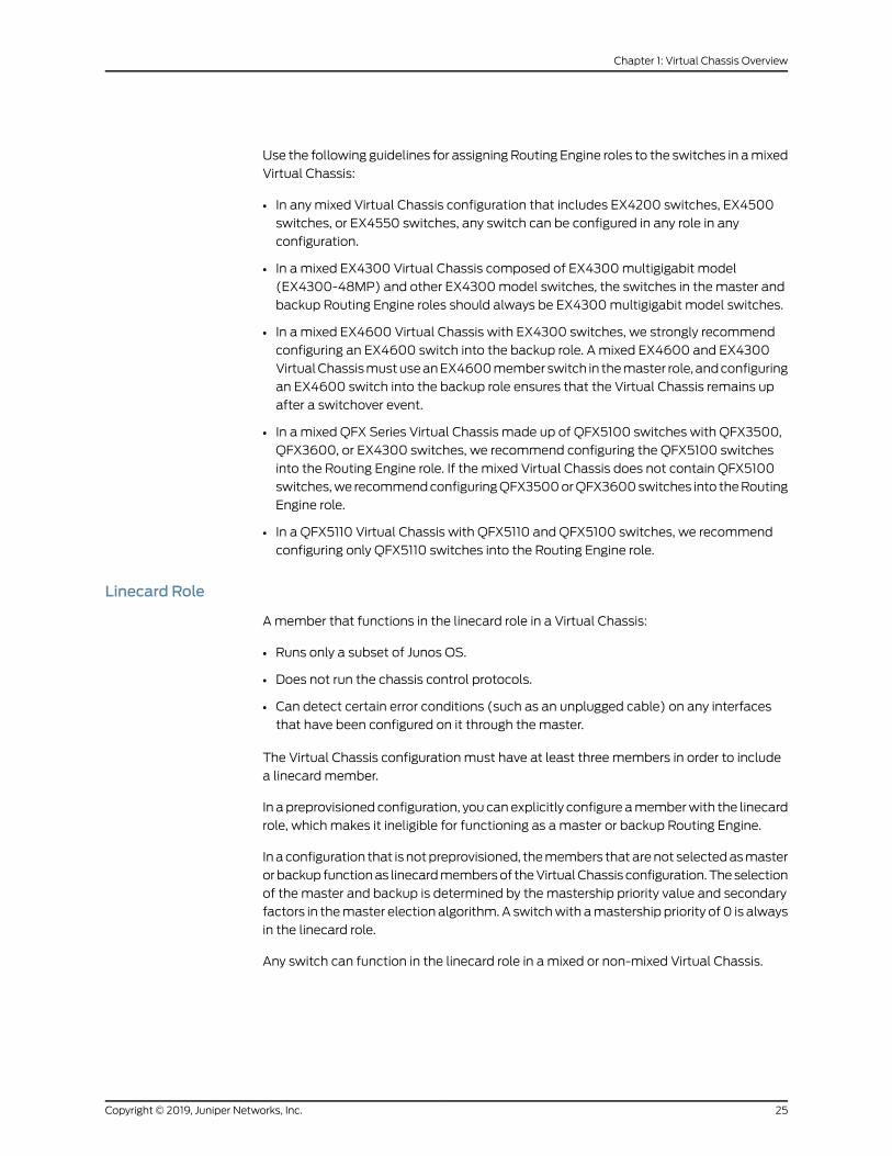
Use the following guidelines for assigning Routing Engine roles to the switches in amixed
Virtual Chassis:
• In any mixed Virtual Chassis configuration that includes EX4200 switches, EX4500
switches, or EX4550 switches, any switch can be configured in any role in any
configuration.
• In a mixed EX4300 Virtual Chassis composed of EX4300multigigabit model
(EX4300-48MP)andotherEX4300model switches, theswitches in theRoutingEngine
role should always be EX4300multigigabit model switches.
• In a mixed EX4600 Virtual Chassis with EX4300 switches, an EX4600 switch must
assume themaster role.
• In a mixed QFX Series Virtual Chassis made up of QFX5100 switches with QFX3500,
QFX3600, or EX4300 switches, we recommend configuring QFX5100 switches into
theRoutingEngine role. If themixedVirtualChassisdoesnotcontainQFX5100switches,
we recommend configuring QFX3500 or QFX3600 switches into the Routing Engine
role.
• In a QFX5110 Virtual Chassis with QFX5110 and QFX5100 switches, we recommend
configuring only QFX5110 switches into the Routing Engine role.
Backup Routing Engine Role
Themember that functions in the backup Routing Engine role in a Virtual Chassis:
• Maintains a state of readiness to take over themaster Routing Engine role if themaster
fails.
• Runs Junos OS for the switches as a backup Routing Engine.
• Synchronizes with themaster in terms of protocol states, forwarding tables, and other
information, so that it is prepared topreserve routing informationandmaintain network
connectivity without disruption in case the master is unavailable.
Youmust have at least twomember switches in theVirtual Chassis configuration in order
to have a backup Routing Engine member.
In a preprovisioned configuration, one of the twomembers assigned as routing-engine
functions in the backup role. The selection of whichmember assigned as routing-engine
functions as master and which as backup is determined by the software based on the
master election algorithm. See Understanding How the Master in a Virtual Chassis Is
Elected.
In a configuration that is not preprovisioned, the selection of the master and backup is
determined by themastership priority value and secondary factors in themaster election
algorithm.
Copyright © 2019, Juniper Networks, Inc.24
Virtual Chassis Feature Guide for EX9200 Switches
Use the following guidelines for assigning Routing Engine roles to the switches in amixed
Virtual Chassis:
• In any mixed Virtual Chassis configuration that includes EX4200 switches, EX4500
switches, or EX4550 switches, any switch can be configured in any role in any
configuration.
• In a mixed EX4300 Virtual Chassis composed of EX4300multigigabit model
(EX4300-48MP) and other EX4300model switches, the switches in the master and
backup Routing Engine roles should always be EX4300multigigabit model switches.
• In a mixed EX4600 Virtual Chassis with EX4300 switches, we strongly recommend
configuring an EX4600 switch into the backup role. A mixed EX4600 and EX4300
VirtualChassismustuseanEX4600memberswitch in themaster role, andconfiguring
an EX4600 switch into the backup role ensures that the Virtual Chassis remains up
after a switchover event.
• In a mixed QFX Series Virtual Chassis made up of QFX5100 switches with QFX3500,
QFX3600, or EX4300 switches, we recommend configuring the QFX5100 switches
into the Routing Engine role. If the mixed Virtual Chassis does not contain QFX5100
switches,we recommendconfiguringQFX3500orQFX3600switches into theRouting
Engine role.
• In a QFX5110 Virtual Chassis with QFX5110 and QFX5100 switches, we recommend
configuring only QFX5110 switches into the Routing Engine role.
Linecard Role
Amember that functions in the linecard role in a Virtual Chassis:
• Runs only a subset of Junos OS.
• Does not run the chassis control protocols.
• Can detect certain error conditions (such as an unplugged cable) on any interfaces
that have been configured on it through themaster.
The Virtual Chassis configuration must have at least three members in order to include
a linecard member.
In apreprovisioned configuration, you canexplicitly configure amemberwith the linecard
role, which makes it ineligible for functioning as amaster or backup Routing Engine.
Inaconfiguration that is notpreprovisioned, themembers thatarenot selectedasmaster
orbackup functionas linecardmembersof theVirtualChassis configuration.Theselection
of the master and backup is determined by themastership priority value and secondary
factors in themaster election algorithm. A switchwith amastership priority of 0 is always
in the linecard role.
Any switch can function in the linecard role in a mixed or non-mixed Virtual Chassis.
25Copyright © 2019, Juniper Networks, Inc.
Chapter 1: Virtual Chassis Overview
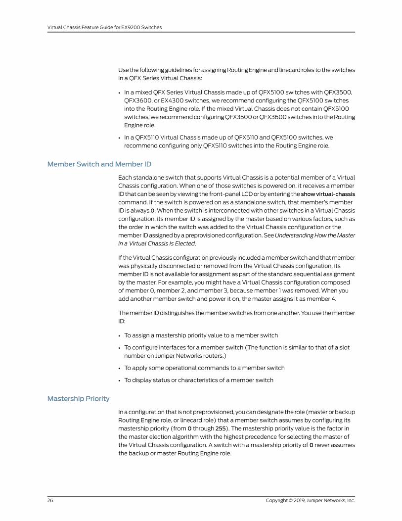
Use the followingguidelines forassigningRoutingEngineand linecard roles to theswitches
in a QFX Series Virtual Chassis:
• In a mixed QFX Series Virtual Chassis made up of QFX5100 switches with QFX3500,
QFX3600, or EX4300 switches, we recommend configuring the QFX5100 switches
into the Routing Engine role. If the mixed Virtual Chassis does not contain QFX5100
switches,we recommendconfiguringQFX3500orQFX3600switches into theRouting
Engine role.
• In a QFX5110 Virtual Chassis made up of QFX5110 and QFX5100 switches, we
recommend configuring only QFX5110 switches into the Routing Engine role.
Member Switch andMember ID
Each standalone switch that supports Virtual Chassis is a potential member of a Virtual
Chassis configuration. When one of those switches is powered on, it receives a member
ID that canbe seenby viewing the front-panel LCDor by entering the showvirtual-chassis
command. If the switch is powered on as a standalone switch, that member’s member
ID is always0.When the switch is interconnectedwith other switches in a Virtual Chassis
configuration, its member ID is assigned by themaster based on various factors, such as
the order in which the switch was added to the Virtual Chassis configuration or the
member IDassignedbyapreprovisionedconfiguration.SeeUnderstandingHowtheMaster
in a Virtual Chassis Is Elected.
If theVirtualChassis configurationpreviously includedamember switchand thatmember
was physically disconnected or removed from the Virtual Chassis configuration, its
member ID is not available for assignment aspart of the standard sequential assignment
by the master. For example, youmight have a Virtual Chassis configuration composed
of member 0, member 2, andmember 3, becausemember 1 was removed. When you
add another member switch and power it on, the master assigns it as member 4.
Themember IDdistinguishes thememberswitches fromoneanother.Youusethemember
ID:
• To assign amastership priority value to amember switch
• To configure interfaces for a member switch (The function is similar to that of a slot
number on Juniper Networks routers.)
• To apply some operational commands to amember switch
• To display status or characteristics of a member switch
Mastership Priority
In aconfiguration that is notpreprovisioned, youcandesignate the role (masterorbackup
Routing Engine role, or linecard role) that a member switch assumes by configuring its
mastership priority (from 0 through 255). Themastership priority value is the factor in
the master election algorithmwith the highest precedence for selecting the master of
the Virtual Chassis configuration. A switch with amastership priority of 0 never assumes
the backup or master Routing Engine role.
Copyright © 2019, Juniper Networks, Inc.26
Virtual Chassis Feature Guide for EX9200 Switches
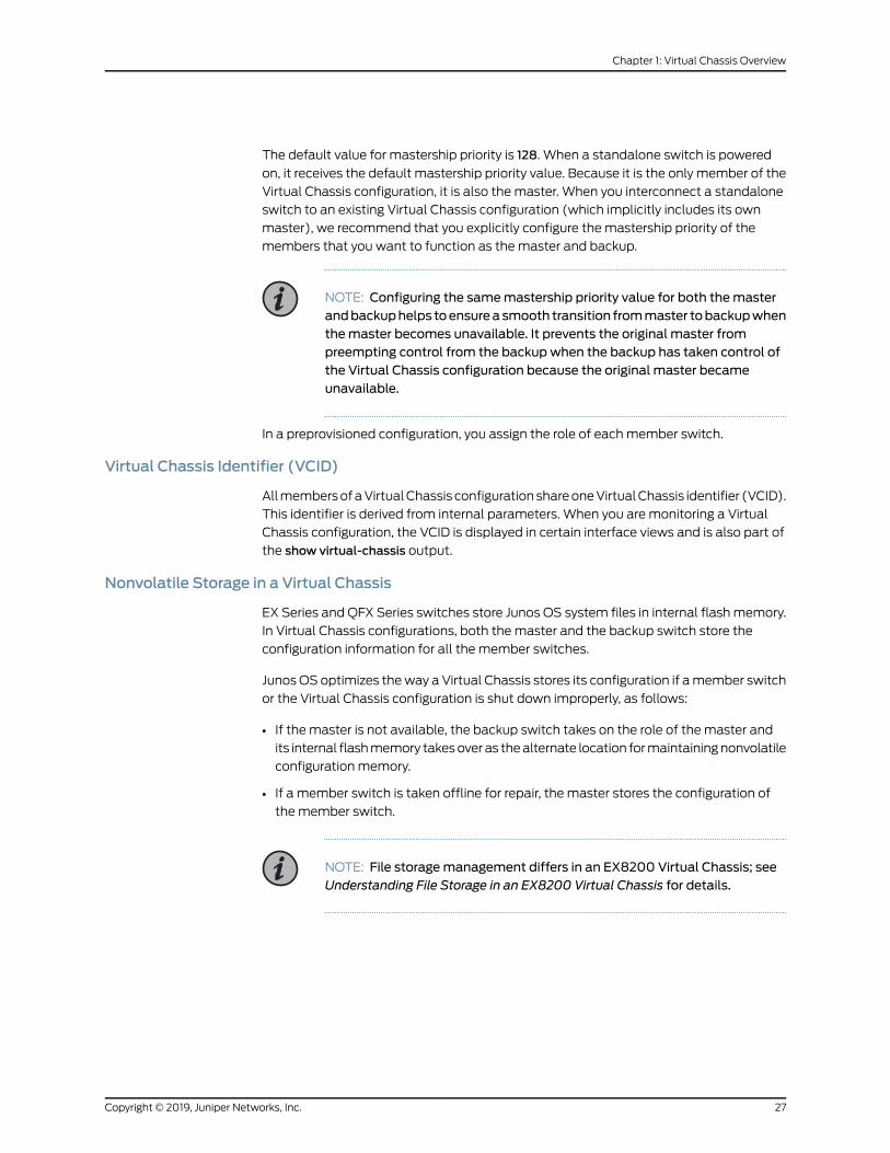
The default value for mastership priority is 128. When a standalone switch is powered
on, it receives the default mastership priority value. Because it is the only member of the
Virtual Chassis configuration, it is also the master. When you interconnect a standalone
switch to an existing Virtual Chassis configuration (which implicitly includes its own
master), we recommend that you explicitly configure the mastership priority of the
members that you want to function as the master and backup.
NOTE: Configuring the samemastership priority value for both themasterandbackuphelps toensureasmooth transition frommaster tobackupwhenthemaster becomes unavailable. It prevents the original master frompreempting control from the backup when the backup has taken control ofthe Virtual Chassis configuration because the original master becameunavailable.
In a preprovisioned configuration, you assign the role of eachmember switch.
Virtual Chassis Identifier (VCID)
AllmembersofaVirtualChassis configurationshareoneVirtualChassis identifier (VCID).
This identifier is derived from internal parameters. When you are monitoring a Virtual
Chassis configuration, the VCID is displayed in certain interface views and is also part of
the show virtual-chassis output.
Nonvolatile Storage in a Virtual Chassis
EX Series and QFX Series switches store Junos OS system files in internal flashmemory.
In Virtual Chassis configurations, both the master and the backup switch store the
configuration information for all the member switches.
JunosOS optimizes theway a Virtual Chassis stores its configuration if amember switch
or the Virtual Chassis configuration is shut down improperly, as follows:
• If the master is not available, the backup switch takes on the role of the master and
its internal flashmemory takesover as thealternate location formaintainingnonvolatile
configuration memory.
• If a member switch is taken offline for repair, the master stores the configuration of
the member switch.
NOTE: File storagemanagement differs in an EX8200 Virtual Chassis; seeUnderstanding File Storage in an EX8200 Virtual Chassis for details.
27Copyright © 2019, Juniper Networks, Inc.
Chapter 1: Virtual Chassis Overview
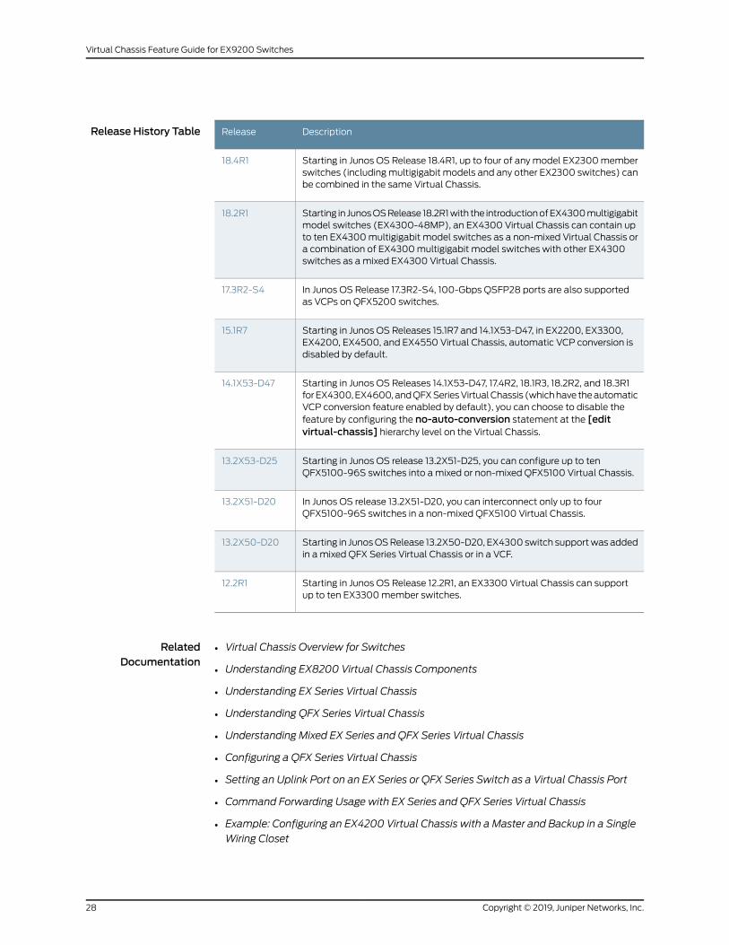
Release History Table DescriptionRelease
Starting in Junos OS Release 18.4R1, up to four of anymodel EX2300memberswitches (includingmultigigabit models and any other EX2300 switches) canbe combined in the same Virtual Chassis.
18.4R1
Starting in JunosOSRelease 18.2R1with the introductionofEX4300multigigabitmodel switches (EX4300-48MP), an EX4300 Virtual Chassis can contain upto ten EX4300multigigabit model switches as a non-mixed Virtual Chassis ora combination of EX4300multigigabit model switches with other EX4300switches as amixed EX4300 Virtual Chassis.
18.2R1
In Junos OS Release 17.3R2-S4, 100-Gbps QSFP28 ports are also supportedas VCPs on QFX5200 switches.
17.3R2-S4
Starting in Junos OS Releases 15.1R7 and 14.1X53-D47, in EX2200, EX3300,EX4200, EX4500, and EX4550 Virtual Chassis, automatic VCP conversion isdisabled by default.
15.1R7
Starting in Junos OS Releases 14.1X53-D47, 17.4R2, 18.1R3, 18.2R2, and 18.3R1forEX4300,EX4600,andQFXSeriesVirtualChassis (whichhave theautomaticVCP conversion feature enabled by default), you can choose to disable thefeature by configuring the no-auto-conversion statement at the [editvirtual-chassis] hierarchy level on the Virtual Chassis.
14.1X53-D47
Starting in Junos OS release 13.2X51-D25, you can configure up to tenQFX5100-96S switches into amixed or non-mixed QFX5100 Virtual Chassis.
13.2X53-D25
In Junos OS release 13.2X51-D20, you can interconnect only up to fourQFX5100-96S switches in a non-mixed QFX5100 Virtual Chassis.
13.2X51-D20
Starting in JunosOSRelease 13.2X50-D20, EX4300switch supportwasaddedin a mixed QFX Series Virtual Chassis or in a VCF.
13.2X50-D20
Starting in Junos OS Release 12.2R1, an EX3300 Virtual Chassis can supportup to ten EX3300member switches.
12.2R1
RelatedDocumentation
• Virtual Chassis Overview for Switches
• Understanding EX8200 Virtual Chassis Components
• Understanding EX Series Virtual Chassis
• Understanding QFX Series Virtual Chassis
• Understanding Mixed EX Series and QFX Series Virtual Chassis
• Configuring a QFX Series Virtual Chassis
• Setting an Uplink Port on an EX Series or QFX Series Switch as a Virtual Chassis Port
• Command Forwarding Usage with EX Series and QFX Series Virtual Chassis
• Example: Configuring an EX4200 Virtual Chassis with a Master and Backup in a Single
Wiring Closet
Copyright © 2019, Juniper Networks, Inc.28
Virtual Chassis Feature Guide for EX9200 Switches
• Example: Configuring an EX4500 Virtual Chassis with a Master and Backup in a Single
Wiring Closet
• Example: Configuring an EX4200 Virtual Chassis Using a Preprovisioned Configuration
File
29Copyright © 2019, Juniper Networks, Inc.
Chapter 1: Virtual Chassis Overview

Copyright © 2019, Juniper Networks, Inc.30
Virtual Chassis Feature Guide for EX9200 Switches
PART 1
Configuring a Virtual Chassis
• Accessing and Configuring a Virtual Chassis and Managing Files on page 33
• Virtual Chassis Ports on page 47
• Upgrading Junos OS in a Virtual Chassis on page 55
• Deleting a Member ID on page 59
• Module Redundancy and GRES on page 61
• Global Roles and Local Roles that Determine Mastership and Switchover
Behavior on page 67
• Minimizing Network Disruption Using Split Detection on page 73
31Copyright © 2019, Juniper Networks, Inc.

Copyright © 2019, Juniper Networks, Inc.32
Virtual Chassis Feature Guide for EX9200 Switches
CHAPTER 2
Accessing and Configuring a VirtualChassis and Managing Files
• Accessing the Virtual Chassis Through the Management Interface on page 34
• Managing Files on Virtual Chassis Member Routers or Switches on page 35
• Virtual Chassis Slot Number Mapping for Use with SNMP on page 36
• Configuring an EX9200 Virtual Chassis on page 38
• Creating and Applying Configuration Groups for a Virtual Chassis on page 43
33Copyright © 2019, Juniper Networks, Inc.
Accessing the Virtual Chassis Through theManagement Interface
Themanagement Ethernet interface (fxp0) on an MX Series router or EX9200 switch is
an out-of-bandmanagement interface, also referred to as amanagement port, that
enables you touseTelnetorSSHtoaccessandmanage thedevice remotely.You typically
configure themanagement interface with an IP address and prefix length when you first
install Junos OS.
You can configure a management Ethernet interface in one of two ways to access a
Virtual Chassis:
• To access the Virtual Chassis as a whole, configure a consistent IP address for the
management interface using themaster-only option. You can use this management
IP address to consistently access the master (primary) Routing Engine in the master
router or switch (protocol master) for the Virtual Chassis.
• To access a specific Routing Engine in an individual member router or switch of the
Virtual Chassis, configure an IP address for one of the following configuration groups:
• member0-re0
• member0-re1
• member1-re0
• member1-re1
BEST PRACTICE: For most management tasks, we recommend that youaccess the Virtual Chassis as a whole through a consistent management IPaddress. For troubleshootingpurposes, however, accessingaspecificRoutingEngine in an individual member router or switchmay be useful.
To access a Virtual Chassis through themanagement Ethernet interface, do one of the
following:
• Configureaconsistentmanagement IPaddress thataccesses theentireVirtualChassis
through themaster Routing Engine in the Virtual Chassis master router or switch.
{master:member0-re0}[edit]user@host# set interfaces fxp0 unit 0 family inet address ip-address/prefix-lengthmaster-only
For example, to access the entire Virtual Chassis via management IP address
10.4.5.33/16:
{master:member0-re0}[edit]user@host# set interfaces fxp0 unit 0 family inet address 10.4.5.33/16master-only
• Configure a management IP address that accesses a specified Routing Engine in an
individual member router or switch in the Virtual Chassis.
Copyright © 2019, Juniper Networks, Inc.34
Virtual Chassis Feature Guide for EX9200 Switches
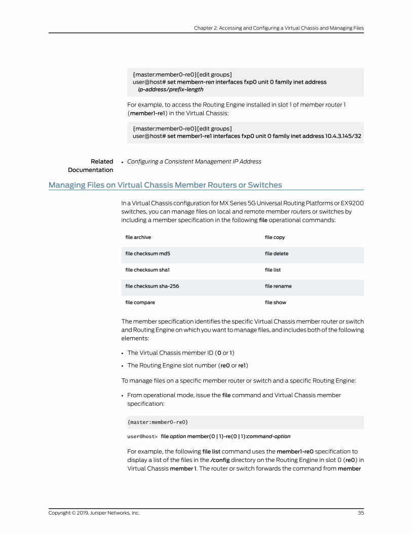
{master:member0-re0}[edit groups]user@host# setmembern-ren interfaces fxp0 unit 0 family inet addressip-address/prefix-length
For example, to access the Routing Engine installed in slot 1 of member router 1
(member1-re1) in the Virtual Chassis:
{master:member0-re0}[edit groups]user@host# setmember1-re1 interfaces fxp0 unit 0 family inet address 10.4.3.145/32
RelatedDocumentation
Configuring a Consistent Management IP Address•
Managing Files on Virtual Chassis Member Routers or Switches
In aVirtualChassis configuration forMXSeries5GUniversalRoutingPlatformsorEX9200
switches, you canmanage files on local and remote member routers or switches by
including amember specification in the following file operational commands:
file copyfile archive
file deletefile checksummd5
file listfile checksum sha1
file renamefile checksum sha-256
file showfile compare
Themember specification identifies the specific Virtual Chassismember router or switch
andRoutingEngineonwhich youwant tomanage files, and includesbothof the following
elements:
• The Virtual Chassis member ID (0 or 1)
• The Routing Engine slot number (re0 or re1)
Tomanage files on a specific member router or switch and a specific Routing Engine:
• From operational mode, issue the file command and Virtual Chassis member
specification:
{master:member0-re0}
user@host> file optionmember(0 | 1)-re(0 | 1):command-option
For example, the following file list command uses themember1-re0 specification to
display a list of the files in the /config directory on the Routing Engine in slot 0 (re0) in
Virtual Chassismember 1. The router or switch forwards the command frommember
35Copyright © 2019, Juniper Networks, Inc.
Chapter 2: Accessing and Configuring a Virtual Chassis and Managing Files
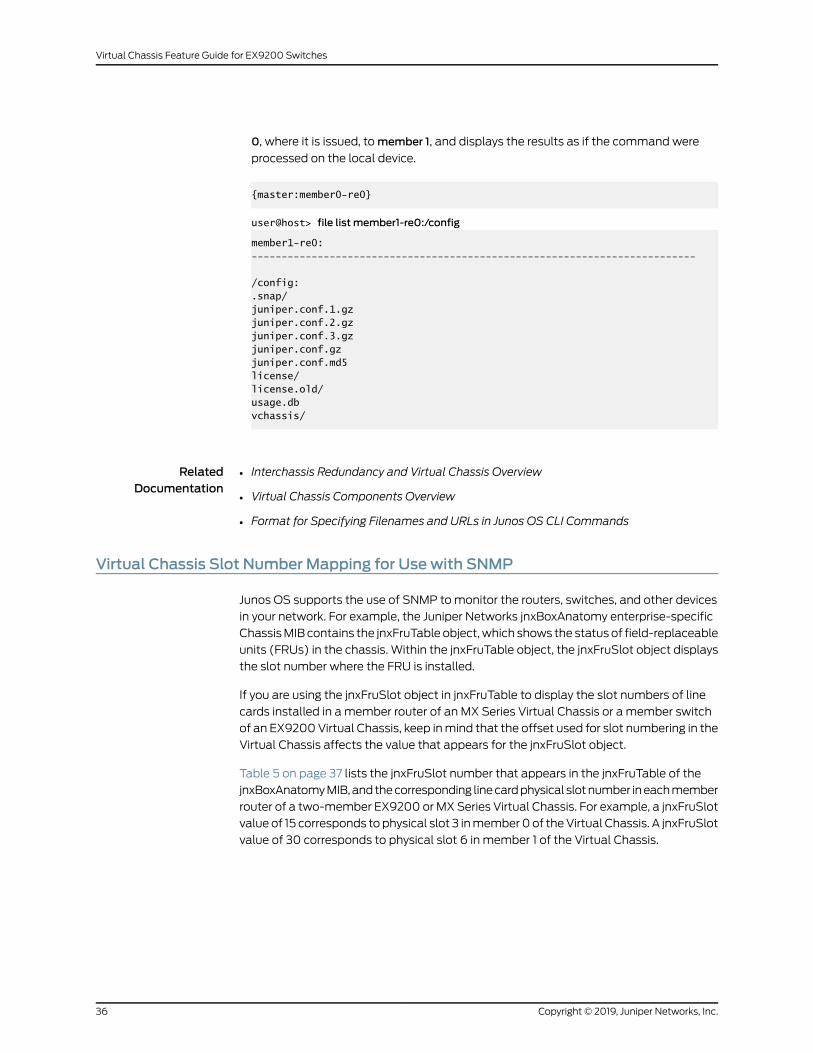
0, where it is issued, tomember 1, and displays the results as if the command were
processed on the local device.
{master:member0-re0}
user@host> file list member1-re0:/config
member1-re0:--------------------------------------------------------------------------
/config:.snap/juniper.conf.1.gzjuniper.conf.2.gzjuniper.conf.3.gzjuniper.conf.gzjuniper.conf.md5license/license.old/usage.dbvchassis/
RelatedDocumentation
Interchassis Redundancy and Virtual Chassis Overview•
• Virtual Chassis Components Overview
• Format for Specifying Filenames and URLs in Junos OS CLI Commands
Virtual Chassis Slot Number Mapping for Use with SNMP
Junos OS supports the use of SNMP tomonitor the routers, switches, and other devices
in your network. For example, the Juniper Networks jnxBoxAnatomy enterprise-specific
ChassisMIB contains the jnxFruTable object,which shows the status of field-replaceable
units (FRUs) in the chassis. Within the jnxFruTable object, the jnxFruSlot object displays
the slot number where the FRU is installed.
If you are using the jnxFruSlot object in jnxFruTable to display the slot numbers of line
cards installed in a member router of an MX Series Virtual Chassis or a member switch
of an EX9200Virtual Chassis, keep inmind that the offset used for slot numbering in the
Virtual Chassis affects the value that appears for the jnxFruSlot object.
Table 5 on page 37 lists the jnxFruSlot number that appears in the jnxFruTable of the
jnxBoxAnatomyMIB,andthecorresponding linecardphysical slotnumber ineachmember
router of a two-member EX9200 orMX Series Virtual Chassis. For example, a jnxFruSlot
value of 15 corresponds to physical slot 3 inmember0of theVirtual Chassis. A jnxFruSlot
value of 30 corresponds to physical slot 6 in member 1 of the Virtual Chassis.
Copyright © 2019, Juniper Networks, Inc.36
Virtual Chassis Feature Guide for EX9200 Switches
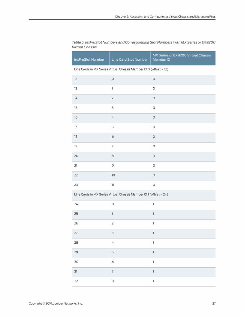
Table5: jnxFruSlotNumbersandCorrespondingSlotNumbers inanMXSeriesorEX9200Virtual Chassis
MXSeries or EX9200 Virtual ChassisMember IDLine Card Slot NumberjnxFruSlot Number
Line Cards in MX Series Virtual Chassis Member ID 0 (offset = 12):
0012
0113
0214
0315
0416
0517
0618
0719
0820
0921
01022
01123
Line Cards in MX Series Virtual Chassis Member ID 1 (offset = 24)
1024
1125
1226
1327
1428
1529
1630
1731
1832
37Copyright © 2019, Juniper Networks, Inc.
Chapter 2: Accessing and Configuring a Virtual Chassis and Managing Files
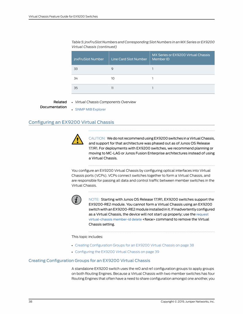
Table5: jnxFruSlotNumbersandCorrespondingSlotNumbers inanMXSeriesorEX9200Virtual Chassis (continued)
MXSeries or EX9200 Virtual ChassisMember IDLine Card Slot NumberjnxFruSlot Number
1933
11034
11135
RelatedDocumentation
Virtual Chassis Components Overview•
• SNMPMIB Explorer
Configuring an EX9200 Virtual Chassis
CAUTION: Wedonot recommendusingEX9200switches inaVirtualChassis,and support for that architecture was phased out as of Junos OS Release17.1R1. For deployments with EX9200 switches, we recommend planning ormoving to MC-LAG or Junos Fusion Enterprise architectures instead of usinga Virtual Chassis.
You configure an EX9200 Virtual Chassis by configuring optical interfaces into Virtual
Chassis ports (VCPs). VCPs connect switches together to form a Virtual Chassis, and
are responsible for passing all data and control traffic betweenmember switches in the
Virtual Chassis.
NOTE: Starting with Junos OS Release 17.1R1, EX9200 switches support theEX9200-RE2module. You cannot form a Virtual Chassis using an EX9200switchwithanEX9200-RE2module installed in it. If inadvertentlyconfiguredas a Virtual Chassis, the device will not start up properly; use the request
virtual-chassis member-id delete <force> command to remove the Virtual
Chassis setting.
This topic includes:
• Creating Configuration Groups for an EX9200 Virtual Chassis on page 38
• Configuring the EX9200 Virtual Chassis on page 39
Creating Configuration Groups for an EX9200 Virtual Chassis
A standalone EX9200 switch uses the re0 and re1 configuration groups to apply groups
on both Routing Engines. Because a Virtual Chassis with twomember switches has four
Routing Engines that often have a need to share configuration amongst one another, you
Copyright © 2019, Juniper Networks, Inc.38
Virtual Chassis Feature Guide for EX9200 Switches
should create four groups—one group for each Routing Engine in the Virtual
Chassis—instead of using the standard re0 and re1 configuration groups.
For a Virtual Chassis configuration consisting of two EX9200 switches, we strongly
recommend that you create and apply on the switch in the master role of the Virtual
Chassis the following configuration groups, instead of using the standard re0 and re1
configuration groups:
• member0-re0
• member0-re1
• member1-re0
• member1-re1
We recommend that youconfigure thesegroupsbefore youconfigure yourVirtualChassis,
to ensure that your configuration is always identical on all Routing Engines in the Virtual
Chassis.
For information on creating and applying configuration groups for your EX9200 Virtual
Chassis, see “CreatingandApplyingConfigurationGroups foraVirtualChassis”onpage43.
Configuring the EX9200 Virtual Chassis
To configure an EX9200 Virtual Chassis:
Before you perform this procedure:
• Ensure that both EX9200member switches in the Virtual Chassis have dual Routing
Engines installed.
• Ensure all Routing Engines on both member switches are running the same version of
Junos OS Release 13.2R2 or later.
• Cable the Virtual Chassis member switches together. See Connecting a Fiber-Optic
Cable, Installing and Removing EX9204 Switch Hardware Components, Installing and
Removing EX9208 Switch Hardware Components, or Installing and Removing EX9214
Switch Hardware Components.
• Create and configure the configuration groups, as described in “Creating Configuration
Groups for an EX9200 Virtual Chassis” on page 38.
1. Log onto the switch that you want to assign as member 0 in your Virtual Chassis.
2. Specify the preprovisioned configuration mode:
[edit virtual-chassis]user@switch-0# set preprovisioned
Youmust use preprovisioned configuration mode to configure an EX9200 Virtual
Chassis.
39Copyright © 2019, Juniper Networks, Inc.
Chapter 2: Accessing and Configuring a Virtual Chassis and Managing Files
3. Configure theVirtualChassis by includingbothmember switches in theVirtualChassis
configuration:
[edit virtual-chassis]user@switch-0# setmember 0 serial-number serial-number role routing-engineuser@switch-0# setmember 1 serial-number serial-number role routing-engine
where serial-number is the chassis serial number of the member switch. You can
retrieve the chassis serial number in the show chassis hardware command output or
by physically viewing the serial number label on the switch. See Locating the Serial
NumberonanEX9204SwitchorComponent,Locating theSerialNumberonanEX9208
SwitchorComponent, orLocating theSerialNumberonanEX9214SwitchorComponent
for additional information
An EX9200Virtual Chassis supports twomember switches. Both switches should be
assigned the routing-engine role.
For instance, if you wanted to configure the switch with chassis serial number
JN1234567ABCasmember0and theswitchwithchassis serial number JN9876543ZYX
as member 1 in your EX9200 Virtual Chassis:
[edit virtual-chassis]user@switch-0# setmember 0 serial-number JN1234567ABC role routing-engineuser@switch-0# setmember 1 serial-number JN9876543ZYX role routing-engine
4. Disable the split andmerge feature:
[edit virtual-chassis]user@switch-0# set no-split-detection
Disabling split andmerge ensures that all interfaces on themember switch in the
master Routing Engine role remain up if the member switch in the backup Routing
Engine role fails.
Split andmerge is enabled by default. If the member switch in the backup Routing
Engine role fails when split andmerge is enabled, all interfaces on all line cards that
do not contain at least one Virtual Chassis port (VCP) on themember switch in the
master Routing Engine role also fail.
5. Commit the configuration:
[edit]user@switch-0# commit
6. Enable Virtual Chassis mode and set the member ID of the switch:
user@switch-0>request virtual-chassis member-id setmember 0
This command will enable virtual-chassis mode and reboot the system. Continue? [yes, no] (no) yes
Youmust reboot both Routing Engines on the switch to complete this step. We
recommend rebooting the switch by answering yes to the prompt that appears onthe screen after entering the request virtual-chassis member-id setmember
Copyright © 2019, Juniper Networks, Inc.40
Virtual Chassis Feature Guide for EX9200 Switches
command, but you can also enter the request system reboot command to rebootoneRoutingEngineon the switchor the requestsystemrebootboth-routing-enginescommand to reboot both Routing Engines simultaneously.
7. Log onto the switch that you want to assign as member 1 in your Virtual Chassis.
8. Enable Virtual Chassis mode and set the member ID of the switch:
user@switch-1>request virtual-chassis member-id setmember 1
This command will enable virtual-chassis mode and reboot the system. Continue? [yes, no] (no) yes
Youmust reboot both Routing Engines on the switch to complete this step. We
recommend rebooting the switch by answering yes to the prompt that appears onthe screen after entering the request virtual-chassis member-id setmembercommand, but you can also enter the request system reboot command to rebootoneRoutingEngineon the switchor the requestsystemrebootboth-routing-enginescommand to reboot both Routing Engines simultaneously.
9. Log back onto member 0 after the reboot is complete. Configure the interfaces that
you want to configure as VCPs as VCPs:
user@switch-0>request virtual-chassis vc-port set fpc-slot fpc-slot-number pic-slotpic-slot-number port port-number
NOTE: A VCP is not created until the request virtual-chassis vc-port setcommand is enabled on the interfaces on themember switches at bothends of the link.
The request virtual-chassis vc-port set is enabled on the interface on theother endof the link in step 10 to complete theVCPconfigurationprocess.
For instance, you can configure port 0 on PIC slot 1 in FPC slot 1 as a VCP using the
following command:
user@switch-0> request virtual-chassis vc-port set fpc-slot 1 pic-slot 1 port 0
vc-port successfully set
10. Log back onto member 1 after the reboot is complete. Configure the interfaces that
you want to configure as VCPs:
user@switch-0>request virtual-chassis vc-port set fpc-slot fpc-slot-number pic-slotpic-slot-number port port-number
41Copyright © 2019, Juniper Networks, Inc.
Chapter 2: Accessing and Configuring a Virtual Chassis and Managing Files
NOTE: You can configuremultiple links into VCPs. If you configureinterfaces of the same speed between themember switches into theVCPs, theVCPsautomatically formaLinkAggregationgroup(LAG)bundle.
You can use the showvirtual-chassis vc-port command to verify that a VCP is created.
You can use the show virtual-chassis command to verify Virtual Chassis status.
Release History Table DescriptionRelease
We do not recommend using EX9200 switches in a Virtual Chassis, andsupport for that architecturewas phased out as of JunosOSRelease 17.1R1.
17.1R1
RelatedDocumentation
Deleting Member IDs in a Virtual Chassis Configuration on page 59•
• Deleting Virtual Chassis Ports in a Virtual Chassis Configuration on page 51
• Configuring Virtual Chassis Ports to Interconnect Member Routers or Switches on
page 48
• Creating and Applying Configuration Groups for a Virtual Chassis on page 43
Copyright © 2019, Juniper Networks, Inc.42
Virtual Chassis Feature Guide for EX9200 Switches
Creating and Applying Configuration Groups for a Virtual Chassis
For a Virtual Chassis configuration consisting of two MX Series routers or two EX9200
switches, each of which supports dual Routing Engines, youmust create and apply on
themaster device of the Virtual Chassis the following configuration groups, instead of
using the standard re0 and re1 configuration groups:
• member0-re0
• member0-re1
• member1-re0
• member1-re1
NOTE: Themembern-ren naming format for configuration groups is reserved
for exclusive use bymember routers or switches in EX9200 or MX SeriesVirtual Chassis configurations.
Using configuration group names of the formmembern-ren in an existing
non-Virtual Chassis configuration or configuration script could interferewithVirtual Chassis operation. This misconfiguration could cause the router orswitch to assign no IP address or an incorrect IP address to the fxp0
managementEthernet interface,andcould result inadisplayof theAmnesiac
prompt during login.
To create and apply configuration group information from the router or switch to be
configured as the master of the Virtual Chassis:
1. In the console window on themaster router or switch (member 0 in this procedure),
create and apply themember0-re0 configuration group.
[edit]user@host# copy groups re0 tomember0-re0user@host# set apply-groupsmember0-re0
2. Delete the standard re0 configuration group from the global configuration onmember
0.
[edit]user@host# delete apply-groups re0user@host# delete groups re0
3. Create and apply themember0-re1 configuration group.
[edit]user@host# copy groups re1 tomember0-re1user@host# set apply-groupsmember0-re1
43Copyright © 2019, Juniper Networks, Inc.
Chapter 2: Accessing and Configuring a Virtual Chassis and Managing Files
4. Delete the standard re1 configuration group from the global configuration onmember
0.
[edit]user@host# delete apply-groups re1user@host# delete groups re1
5. Create and apply themember1-re0 configuration information.
[edit]user@host# set groupsmember1-re0 system host-name host-nameuser@host# set groupsmember1-re0 system backup-router addressuser@host# set groupsmember1-re0 system backup-router destinationdestination-address
user@host# set groupsmember1-re0 system backup-router destinationdestination-address
...user@host# set groupsmember1-re0 interfaces fxp0 unit unit-number family inetaddress address
user@host# set apply-groupsmember1-re0
Thecommands inSteps5and6set the IPaddress for the fxp0management interface
and add an IP route for it in the event that routing becomes inactive.
6. Create and apply themember1-re1 configuration information.
[edit]user@host# set groupsmember1-re1 system host-name host-nameuser@host# set groupsmember1-re1 system backup-router addressuser@host# set groupsmember1-re1 system backup-router destinationdestination-address
user@host# set groupsmember1-re1 system backup-router destinationdestination-address
...user@host# set groupsmember1-re1 interfaces fxp0 unit unit-number family inetaddress address
user@host# set apply-groupsmember1-re1
7. Commit the configuration.
BEST PRACTICE: We recommend that you use the commit synchronize
command to save any configuration changes to the Virtual Chassis.
For anEX9200orMXSeriesVirtual Chassis, the forceoption is thedefault
and only behavior when you issue the commit synchronize command.
IssuingthecommitsynchronizecommandforaVirtualChassisconfiguration
has the same effect as issuing the commit synchronize force command.
Copyright © 2019, Juniper Networks, Inc.44
Virtual Chassis Feature Guide for EX9200 Switches
RelatedDocumentation
• Configuring Interchassis Redundancy for MX Series 3D Universal Edge Routers Using a
Virtual Chassis
• Configuring an EX9200 Virtual Chassis on page 38
• Example: Configuring Interchassis Redundancy for MX Series 3D Universal Edge Routers
Using a Virtual Chassis
• Formore informationabout creatingandmanagingconfigurationgroups, see the Junos
OS CLI User Guide
45Copyright © 2019, Juniper Networks, Inc.
Chapter 2: Accessing and Configuring a Virtual Chassis and Managing Files

Copyright © 2019, Juniper Networks, Inc.46
Virtual Chassis Feature Guide for EX9200 Switches
CHAPTER 3
Virtual Chassis Ports
• Configuring Virtual Chassis Ports to Interconnect Member Routers or
Switches on page 48
• Deleting Virtual Chassis Ports in a Virtual Chassis Configuration on page 51
• Verifying the Operation of Virtual Chassis Ports on page 52
47Copyright © 2019, Juniper Networks, Inc.
Configuring Virtual Chassis Ports to Interconnect Member Routers or Switches
To interconnect the member routers in an MX Series Virtual Chassis, youmust use the
request virtual-chassis vc-port set command to configure network ports into Virtual
Chassis ports on Modular Port Concentrator/Modular Interface Card (MPC/MIC)
interfaces. To interconnect the member switches into an EX9200 Virtual Chassis, you
must use the request virtual-chassis vc-port set command to configure network ports
into Virtual Chassis ports on line card interfaces. After the request virtual-chassis vc-port
set is configured on both ends of the link, a Virtual Chassis port that is dedicated to the
task of interconnectingmember devices is created and the link can no longer be used as
a standard network port.
NOTE: If you issue the request virtual-chassis vc-port set commandwithout
first installing anMX Virtual Chassis Redundancy Feature Pack license onbothmember routers in an MX Series Virtual Chassis, the software displaysa warningmessage that you are operating without a valid Virtual Chassissoftware license.
A software license is not needed to create an EX9200 Virtual Chassis.
To configure Virtual Chassis ports:
Copyright © 2019, Juniper Networks, Inc.48
Virtual Chassis Feature Guide for EX9200 Switches
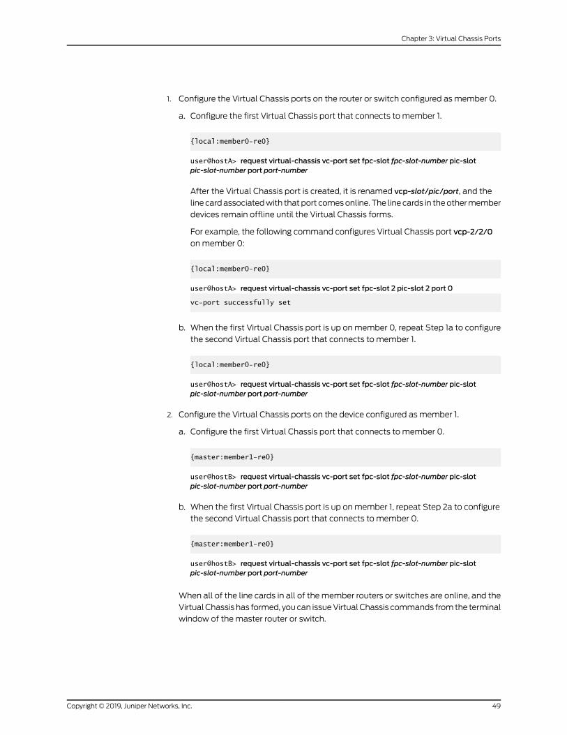
1. Configure the Virtual Chassis ports on the router or switch configured as member 0.
a. Configure the first Virtual Chassis port that connects to member 1.
{local:member0-re0}
user@hostA> request virtual-chassis vc-port set fpc-slot fpc-slot-number pic-slotpic-slot-number port port-number
After the Virtual Chassis port is created, it is renamed vcp-slot/pic/port, and the
linecardassociatedwith thatport comesonline. The linecards in theothermember
devices remain offline until the Virtual Chassis forms.
For example, the following command configures Virtual Chassis port vcp-2/2/0
onmember 0:
{local:member0-re0}
user@hostA> request virtual-chassis vc-port set fpc-slot 2 pic-slot 2 port 0
vc-port successfully set
b. When the first Virtual Chassis port is up onmember 0, repeat Step 1a to configure
the second Virtual Chassis port that connects to member 1.
{local:member0-re0}
user@hostA> request virtual-chassis vc-port set fpc-slot fpc-slot-number pic-slotpic-slot-number port port-number
2. Configure the Virtual Chassis ports on the device configured as member 1.
a. Configure the first Virtual Chassis port that connects to member 0.
{master:member1-re0}
user@hostB> request virtual-chassis vc-port set fpc-slot fpc-slot-number pic-slotpic-slot-number port port-number
b. When the first Virtual Chassis port is up onmember 1, repeat Step 2a to configure
the second Virtual Chassis port that connects to member 0.
{master:member1-re0}
user@hostB> request virtual-chassis vc-port set fpc-slot fpc-slot-number pic-slotpic-slot-number port port-number
When all of the line cards in all of themember routers or switches are online, and the
VirtualChassis has formed, youcan issueVirtualChassis commands fromthe terminal
window of the master router or switch.
49Copyright © 2019, Juniper Networks, Inc.
Chapter 3: Virtual Chassis Ports
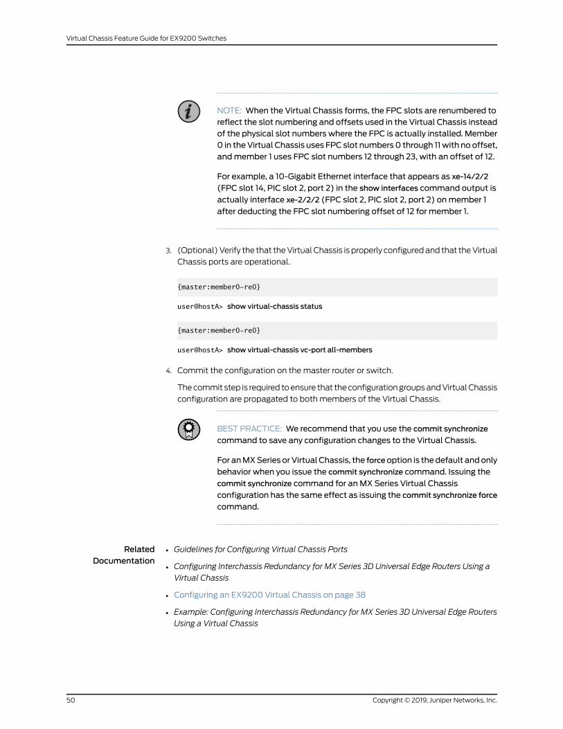
NOTE: When the Virtual Chassis forms, the FPC slots are renumbered toreflect the slot numbering and offsets used in the Virtual Chassis insteadof the physical slot numbers where the FPC is actually installed. Member0 in theVirtual Chassis uses FPC slot numbers0 through 11with no offset,andmember 1 uses FPC slot numbers 12 through 23, with an offset of 12.
For example, a 10-Gigabit Ethernet interface that appears as xe-14/2/2
(FPC slot 14, PIC slot 2, port 2) in the show interfaces command output is
actually interface xe-2/2/2 (FPC slot 2, PIC slot 2, port 2) onmember 1
after deducting the FPC slot numbering offset of 12 for member 1.
3. (Optional)Verify the that theVirtualChassis is properly configuredand that theVirtual
Chassis ports are operational.
{master:member0-re0}
user@hostA> show virtual-chassis status
{master:member0-re0}
user@hostA> show virtual-chassis vc-port all-members
4. Commit the configuration on themaster router or switch.
Thecommit step is required toensure that theconfigurationgroupsandVirtualChassis
configuration are propagated to both members of the Virtual Chassis.
BEST PRACTICE: We recommend that you use the commit synchronize
command to save any configuration changes to the Virtual Chassis.
For anMXSeries orVirtual Chassis, the forceoption is thedefault andonly
behavior when you issue the commit synchronize command. Issuing the
commit synchronize command for an MX Series Virtual Chassis
configuration has the same effect as issuing the commit synchronize force
command.
RelatedDocumentation
Guidelines for Configuring Virtual Chassis Ports•
• Configuring Interchassis Redundancy for MX Series 3D Universal Edge Routers Using a
Virtual Chassis
• Configuring an EX9200 Virtual Chassis on page 38
• Example: Configuring Interchassis Redundancy for MX Series 3D Universal Edge Routers
Using a Virtual Chassis
Copyright © 2019, Juniper Networks, Inc.50
Virtual Chassis Feature Guide for EX9200 Switches
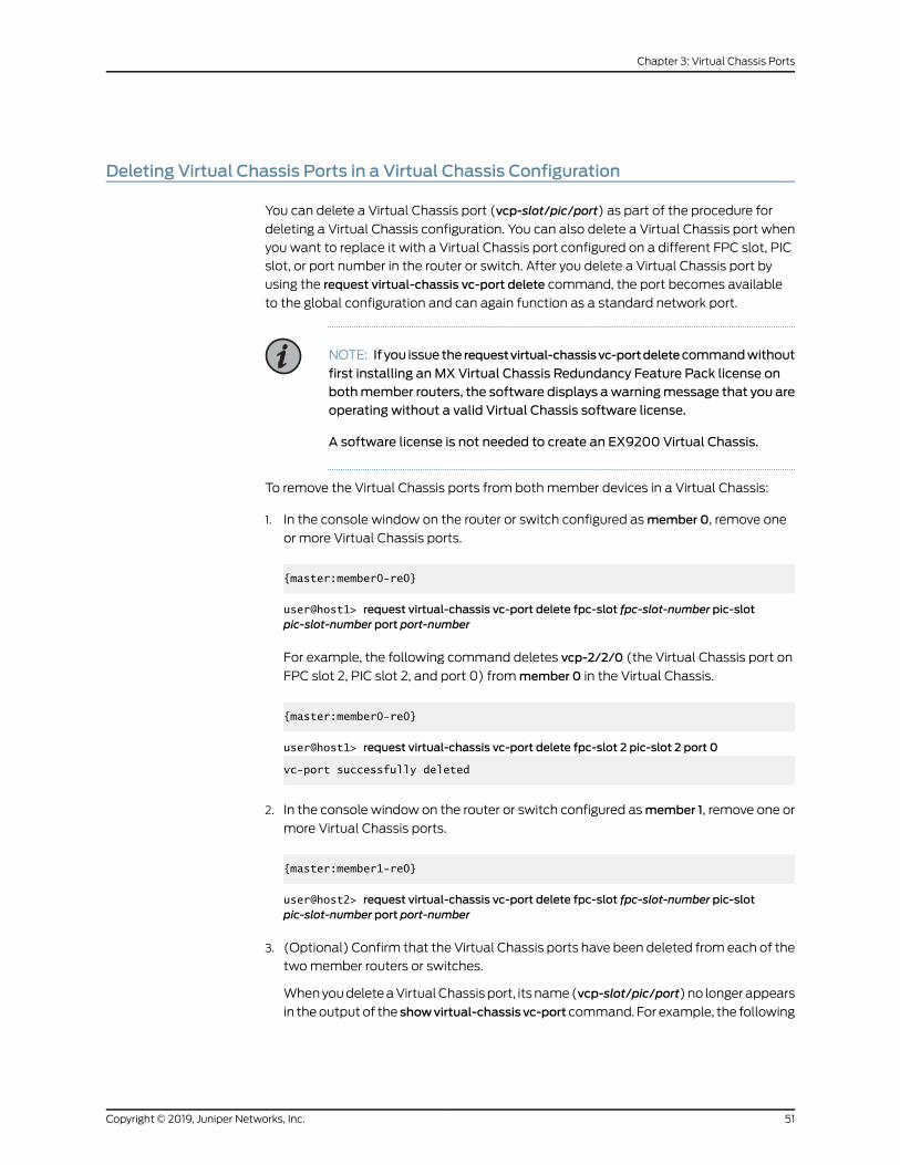
Deleting Virtual Chassis Ports in a Virtual Chassis Configuration
You can delete a Virtual Chassis port (vcp-slot/pic/port) as part of the procedure for
deleting a Virtual Chassis configuration. You can also delete a Virtual Chassis port when
you want to replace it with a Virtual Chassis port configured on a different FPC slot, PIC
slot, or port number in the router or switch. After you delete a Virtual Chassis port by
using the request virtual-chassis vc-port delete command, the port becomes available
to the global configuration and can again function as a standard network port.
NOTE: If you issue the requestvirtual-chassisvc-portdeletecommandwithout
first installing anMX Virtual Chassis Redundancy Feature Pack license onbothmember routers, the software displays awarningmessage that you areoperating without a valid Virtual Chassis software license.
A software license is not needed to create an EX9200 Virtual Chassis.
To remove the Virtual Chassis ports from bothmember devices in a Virtual Chassis:
1. In the console window on the router or switch configured asmember 0, remove one
or more Virtual Chassis ports.
{master:member0-re0}
user@host1> request virtual-chassis vc-port delete fpc-slot fpc-slot-number pic-slotpic-slot-number port port-number
For example, the following command deletes vcp-2/2/0 (the Virtual Chassis port on
FPC slot 2, PIC slot 2, and port 0) frommember 0 in the Virtual Chassis.
{master:member0-re0}
user@host1> request virtual-chassis vc-port delete fpc-slot 2 pic-slot 2 port 0
vc-port successfully deleted
2. In the console window on the router or switch configured asmember 1, remove one or
more Virtual Chassis ports.
{master:member1-re0}
user@host2> request virtual-chassis vc-port delete fpc-slot fpc-slot-number pic-slotpic-slot-number port port-number
3. (Optional) Confirm that the Virtual Chassis ports have been deleted from each of the
twomember routers or switches.
WhenyoudeleteaVirtualChassisport, itsname(vcp-slot/pic/port)no longerappears
in theoutput of the showvirtual-chassisvc-port command. For example, the following
51Copyright © 2019, Juniper Networks, Inc.
Chapter 3: Virtual Chassis Ports
output for the showvirtual-chassisvc-portcommandoneachmember router or switch
confirms that all Virtual Chassis ports have been deleted from bothmember devices.
For member 0 (host1):
{master:member0-re0}
user@host1> show virtual-chassis vc-port all-members
member0:--------------------------------------------------------------------------
For member 1 (host2):
{backup:member1-re0}
user@host2> show virtual-chassis vc-port all-members
member1:--------------------------------------------------------------------------
TIP: Deleting and then re-creating a Virtual Chassis port configurationmaycause the Virtual Chassis port to appear as Absent in the Status column of
the showvirtual-chassisvc-portcommanddisplay.To resolve this issue, reboot
the FPC that hosts the re-created Virtual Chassis port.
RelatedDocumentation
Deleting a Virtual Chassis Configuration for MX Series 3D Universal Edge Routers•
• Configuring an EX9200 Virtual Chassis on page 38
• Example:DeletingaVirtualChassisConfiguration forMXSeries 3DUniversal EdgeRouters
• Guidelines for Configuring Virtual Chassis Ports
Verifying the Operation of Virtual Chassis Ports
Purpose Verify that theVirtualChassisports inanMXSeriesorEX9200VirtualChassis areproperly
configured and operational.
Action To display the status of the Virtual Chassis ports for both member routers or switches
in the Virtual Chassis:
•
user@host> show virtual-chassis vc-port all-members
• To display the status of the Virtual Chassis ports for a specified member router or
switch in the Virtual Chassis:
user@host> show virtual-chassis vc-port membermember-id
Copyright © 2019, Juniper Networks, Inc.52
Virtual Chassis Feature Guide for EX9200 Switches
• To display the status of the Virtual Chassis ports for the member router or switch on
which you are issuing the command:
user@host> show virtual-chassis vc-port local
RelatedDocumentation
• Configuring Interchassis Redundancy for MX Series 3D Universal Edge Routers Using a
Virtual Chassis
• Configuring an EX9200 Virtual Chassis on page 38
• Example: Configuring Interchassis Redundancy for MX Series 3D Universal Edge Routers
Using a Virtual Chassis
53Copyright © 2019, Juniper Networks, Inc.
Chapter 3: Virtual Chassis Ports

Copyright © 2019, Juniper Networks, Inc.54
Virtual Chassis Feature Guide for EX9200 Switches
CHAPTER 4
Upgrading Junos OS in a Virtual Chassis
• Upgrading Junos OS Software in an EX9200 Virtual Chassis on page 55
Upgrading Junos OS Software in an EX9200 Virtual Chassis
You can upgrade the Junos OS in an EX9200 Virtual Chassis by installing Junos OS
software onto each Routing Engine in the Virtual Chassis, and rebooting each Routing
Engine individually to complete the installation. Both member switches in the EX9200
Virtual Chassis must have dual Routing Engines installed.
NOTE: Makesureall fourRoutingEngines in theVirtualChassis (bothRoutingEngines in themaster switchandbothRoutingEngines in thebackupswitch)are running the same version of Junos OS software.
CAUTION: Support for EX9200 Virtual Chassis was phased out as of JunosOSRelease 17.1R1, so do not upgrade an EX9200Virtual Chassis to Junos OSRelease 17.1R1 and beyond. For deployments with EX9200 switches, werecommend planning or moving to MC-LAG or Junos Fusion Enterprisearchitectures instead of using a Virtual Chassis.
To upgrade Junos OS software in an EX9200 Virtual Chassis:
1. Downloadthe JunosOSsoftwarepackage to themasterRoutingEngineon themaster
switch in the Virtual Chassis (VC-M).
See Downloading Software.
2. Disable nonstop active routing (NSR) from themaster Routing Engine on themaster
switch in the Virtual Chassis (VC-M):
{master:member0-re0}[edit routing-options]
user@switch# deactivate nonstop-routing
55Copyright © 2019, Juniper Networks, Inc.
3. Disable graceful Routing Engine switchover (GRES) from themaster Routing Engine
on themaster switch in the Virtual Chassis (VC-M):
{master:member0-re0}[edit chassis redundancy]
user@switch# deactivate graceful-switchover
4. Commit the configuration.
5. Exit CLI configuration mode.
{master:member0-re0}[edit]
user@switch# exit
6. Install the JunosOSsoftwarepackageontoeachRoutingEngine in theVirtualChassis:
{master:member0-re0}
user@switch> request system software add package-name
On a properly formed Virtual Chassis, entering the request system software addpackage-name from themaster Routing Engine on themaster switch in the Virtual
Chassis (VC-M)propagates the JunosOSsoftwarepackage toall fourRoutingEngines
in the Virtual Chassis.
7. Enter CLI configuration mode, and re-enable GRES:
{master:member0-re0}
user@switch> configure
[edit]
user@switch# edit chassis redundancy
[edit chassis redundancy]
user@switch# activate graceful-switchover
8. Re-enable NSR:
{master:member0-re0}[edit routing-options]
user@switch# activate nonstop-routing
Copyright © 2019, Juniper Networks, Inc.56
Virtual Chassis Feature Guide for EX9200 Switches
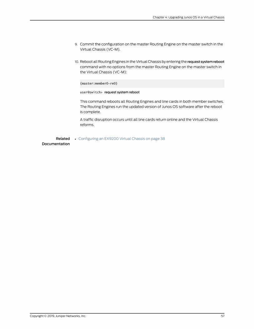
9. Commit the configuration on themaster Routing Engine on themaster switch in the
Virtual Chassis (VC-M).
10. RebootallRoutingEngines in theVirtualChassisbyentering the requestsystemreboot
command with no options from themaster Routing Engine on themaster switch in
the Virtual Chassis (VC-M):
{master:member0-re0}
user@switch> request system reboot
This command reboots all Routing Engines and line cards in both member switches.
The Routing Engines run the updated version of Junos OS software after the reboot
is complete.
A traffic disruption occurs until all line cards return online and the Virtual Chassis
reforms.
RelatedDocumentation
• Configuring an EX9200 Virtual Chassis on page 38
57Copyright © 2019, Juniper Networks, Inc.
Chapter 4: Upgrading Junos OS in a Virtual Chassis

Copyright © 2019, Juniper Networks, Inc.58
Virtual Chassis Feature Guide for EX9200 Switches
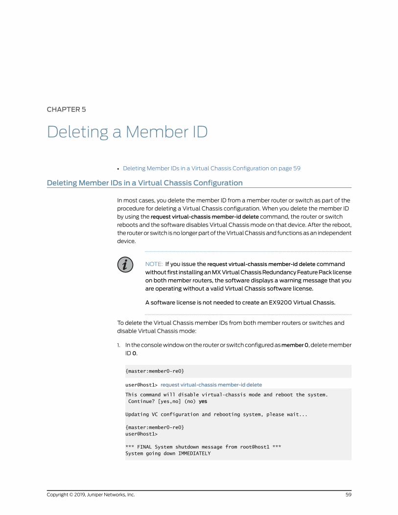
CHAPTER 5
Deleting a Member ID
• Deleting Member IDs in a Virtual Chassis Configuration on page 59
DeletingMember IDs in a Virtual Chassis Configuration
In most cases, you delete the member ID from amember router or switch as part of the
procedure for deleting a Virtual Chassis configuration. When you delete the member ID
by using the request virtual-chassis member-id delete command, the router or switch
reboots and the software disables Virtual Chassismode on that device. After the reboot,
the routeror switch isno longerpartof theVirtualChassisand functionsasan independent
device.
NOTE: If you issue the request virtual-chassis member-id delete command
without first installinganMXVirtualChassisRedundancyFeaturePack licenseon bothmember routers, the software displays a warningmessage that youare operating without a valid Virtual Chassis software license.
A software license is not needed to create an EX9200 Virtual Chassis.
To delete the Virtual Chassis member IDs from bothmember routers or switches and
disable Virtual Chassis mode:
1. In theconsolewindowon the routeror switchconfiguredasmember0, deletemember
ID 0.
{master:member0-re0}
user@host1> request virtual-chassis member-id delete
This command will disable virtual-chassis mode and reboot the system. Continue? [yes,no] (no) yes
Updating VC configuration and rebooting system, please wait...
{master:member0-re0}user@host1>
*** FINAL System shutdown message from root@host1 *** System going down IMMEDIATELY
59Copyright © 2019, Juniper Networks, Inc.
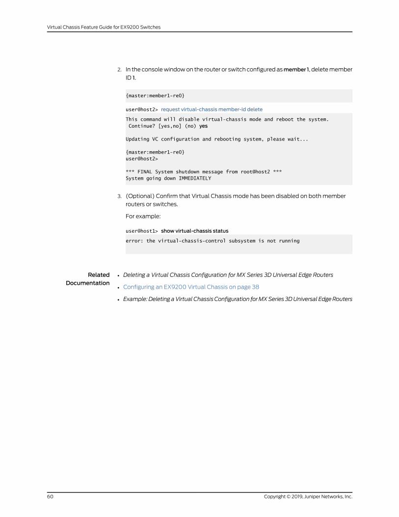
2. In the consolewindowon the router or switch configured asmember 1, deletemember
ID 1.
{master:member1-re0}
user@host2> request virtual-chassis member-id delete
This command will disable virtual-chassis mode and reboot the system. Continue? [yes,no] (no) yes
Updating VC configuration and rebooting system, please wait...
{master:member1-re0}user@host2>
*** FINAL System shutdown message from root@host2 *** System going down IMMEDIATELY
3. (Optional) Confirm that Virtual Chassis mode has been disabled on both member
routers or switches.
For example:
user@host1> show virtual-chassis status
error: the virtual-chassis-control subsystem is not running
RelatedDocumentation
• Deleting a Virtual Chassis Configuration for MX Series 3D Universal Edge Routers
• Configuring an EX9200 Virtual Chassis on page 38
• Example:DeletingaVirtualChassisConfiguration forMXSeries 3DUniversal EdgeRouters
Copyright © 2019, Juniper Networks, Inc.60
Virtual Chassis Feature Guide for EX9200 Switches
CHAPTER 6
Module Redundancy and GRES
• Targeted Traffic Distribution on Aggregated Ethernet Interfaces in a Virtual
Chassis on page 61
• Configuring Module Redundancy for a Virtual Chassis on page 62
• Determining GRES Readiness in a Virtual Chassis Configuration on page 64
Targeted Traffic Distribution on Aggregated Ethernet Interfaces in a Virtual Chassis
By default, member routers or switches in an EX9200 or MX Series Virtual Chassis use
hash-based traffic distribution for subscriber interfaces in aggregated Ethernet bundles
configuredwithout linkprotection. Thehash-basedmodeldistributes subscriber interface
traffic over multiple links in the bundle, enabling you to load balancemultiple traffic
flows through the logical subscriber interface.
Starting in Junos OS Release 13.2, as an alternative to using hash-based distribution in
an EX9200 or MX Series Virtual Chassis, you can configure targeted traffic distribution
for IP demultiplexing (demux) or VLAN demux subscriber interfaces in an aggregated
Ethernet bundle that is configured without link protection.
• Targeted Distribution in a Virtual Chassis on page 61
• Benefits of Targeted Distribution on page 62
Targeted Distribution in a Virtual Chassis
Targeted distribution enables you to configure the Virtual Chassis to send (target) all
egress data traffic for a logical subscriber interface across a single member link in an
aggregated Ethernet bundle, also referred to as an IEEE 802.3ad link aggregation group
(LAG) bundle. You configure targeted distribution for a demux subscriber interface on
the Virtual Chassis master router or switch.
With targeted distribution, the router or switch in a Virtual Chassis assigns the primary
member link and backupmember link for the aggregated Ethernet bundle across all
Virtual Chassis port links that belong to the aggregated Ethernet bundle. To accomplish
load balancing, the router or switch evenly distributes the demux subscriber interfaces
over these member links.
61Copyright © 2019, Juniper Networks, Inc.
Benefits of Targeted Distribution
Targeted distribution is especially useful in a Virtual Chassis configuration in which
subscriber traffic enters through a Virtual Chassis port on onemember router or switch
and exits through a Virtual Chassis port on a different member router or switch. By
combining Virtual Chassis ports from different member router or switches as member
links of the aggregated Ethernet bundle, targeted distribution provides increased
redundancy in the event of a chassis or link failure.
Release History Table DescriptionRelease
Starting in JunosOSRelease 13.2, asanalternative tousinghash-baseddistributionin an EX9200 or MX Series Virtual Chassis, you can configure targeted trafficdistribution for IP demultiplexing (demux) or VLAN demux subscriber interfacesin an aggregated Ethernet bundle that is configured without link protection.
13.2
RelatedDocumentation
Redundancy Mechanisms on Aggregated Ethernet Interfaces in a Virtual Chassis•
• Configuring Module Redundancy for a Virtual Chassis on page 62
• Configuring Chassis Redundancy for a Virtual Chassis
ConfiguringModule Redundancy for a Virtual Chassis
By default, a router or switch uses link redundancy for aggregated Ethernet interfaces
(bundles) configuredwith targeted traffic distribution. Starting in Junos OS Release 13.2,
as an alternative to using link redundancy, you can configure module redundancy, also
knownasFPCredundancy, foraVirtualChassis configuredwith targeted trafficdistribution
for IP demux or VLAN demux subscribers on aggregated Ethernet interfaces.
In a Virtual Chassis, module redundancy assigns the primary link and backup link to
differentMPC/MICmodules or line cards, regardless of the Virtual Chassis role (master
or backup) of the member device in which the module is installed. Module redundancy
provides redundancy protection if a module or a link in the Virtual Chassis fails.
Before you begin:
• ConfigureaVirtualChassis consistingof twoMXSeries routersor twoEX9200switches.
See Example: Configuring Interchassis Redundancy for MX Series 3D Universal Edge
Routers Using a Virtual Chassis
• Ensure that the aggregated Ethernet bundle is configuredwithout link protection.
See Configuring Aggregated Ethernet Link Protection
Copyright © 2019, Juniper Networks, Inc.62
Virtual Chassis Feature Guide for EX9200 Switches

To configure module redundancy:
1. Log in to the console on themaster device of the Virtual Chassis.
2. Specify that you want to configure the demux logical interface.
{master:member0-re0} [edit]user@host# edit interfaces demux0 unit logical-unit-number
3. Enable targeted distribution for the interface.
{master:member0-re0} [edit intefaces demux0 unit logical-unit-number]user@host# set targeted-distribution
4. Specify the aggregated Ethernet bundle for which you want to configure module
redundancy.
{master:member0-re0} [edit]user@host# edit interfaces aenumber aggregated-ether-options
5. Enable module (FPC) redundancy for the specified aggregated Ethernet bundle.
{master:member0-re0} [edit interfaces aenumber aggregated-ether-options]user@host# set logical-interface-fpc-redundancy
BEST PRACTICE: We recommend that you do not configure bothmodule(FPC) redundancyandchassis redundancy for thesameaggregatedEthernetinterface in the Virtual Chassis. If you do, module redundancy takesprecedence over chassis redundancy.
Release History Table DescriptionRelease
Starting in Junos OS Release 13.2, as an alternative to using link redundancy, youcan configure module redundancy, also known as FPC redundancy, for a VirtualChassis configuredwith targeted traffic distribution for IP demuxor VLANdemuxsubscribers on aggregated Ethernet interfaces.
13.2
RelatedDocumentation
Targeted Traffic Distribution on Aggregated Ethernet Interfaces in a Virtual Chassis on
page 61
•
• Redundancy Mechanisms on Aggregated Ethernet Interfaces in a Virtual Chassis
• Configuring Chassis Redundancy for a Virtual Chassis
63Copyright © 2019, Juniper Networks, Inc.
Chapter 6: Module Redundancy and GRES
Determining GRES Readiness in a Virtual Chassis Configuration
Depending on the configuration, a variable amount of time is required before a router or
switch is ready to perform a graceful Routing Engine switchover (GRES). Attempting a
GRES operation before the device is ready can cause system errors and unexpected
behavior.
To determine whether themember routers or switches in a Virtual Chassis configuration
are ready for a GRES operation from a database synchronization perspective, you can
issue the request virtual-chassis routing-enginemaster switch check command from the
Virtual Chassismaster router or switch (VC-Mm) before you initiate the GRES operation.
Using the request virtual-chassis routing-enginemaster switch check command before
you initiate the GRES operation ensures that the subscriber management and kernel
databases on bothmember routers or switches are synchronized and ready for theGRES
operation.
To determine whether the member routers or switches are ready for GRES from a
database synchronization perspective:
1. Issue the request virtual-chassis routing-enginemaster switch check command from
the Virtual Chassis master router or switch (VC-Mm).
{master:member0-re0}
user@host> request virtual-chassis routing-enginemaster switch check
The request virtual-chassis routing-enginemaster switch check command checks
various system and database components on themember routers or switches to
determine whether they are ready for GRES, but does not initiate the global GRES
operation itself. The readiness check includes ensuring that a system timer, which
expires after 300 seconds, completes before the global GRES operation begins.
2. Review the results of the request virtual-chassis routing-enginemaster switch check
command todeterminewhether themember routersor switchesare ready for aGRES
operation from a database synchronization perspective.
• If the member routers or switches are ready for GRES, the request virtual-chassis
routing-enginemaster switchcheck commanddisplays amessageconfirmingGRES
readiness. For example:
{master:member0-re0}
user@host> request virtual-chassis routing-enginemaster switch check
Switchover Ready
• If themember routersor switchesarenot ready forGRES, the requestvirtual-chassis
routing-enginemaster switch check command displays information about the
readiness of the system. For example:
Copyright © 2019, Juniper Networks, Inc.64
Virtual Chassis Feature Guide for EX9200 Switches
{master:member0-re0}
user@host> request virtual-chassis routing-enginemaster switch check
error: chassisd Not ready for mastership switch, try after 217 secs.mastership switch request NOT honored, backup not ready
The specific command output differs depending on the GRES readiness state of
the member routers or switches.
RelatedDocumentation
• Switchover Behavior in an MX Series Virtual Chassis
• Virtual Chassis Components Overview
• Global Roles and Local Roles in a Virtual Chassis on page 69
• Understanding Graceful Routing Engine Switchover
65Copyright © 2019, Juniper Networks, Inc.
Chapter 6: Module Redundancy and GRES

Copyright © 2019, Juniper Networks, Inc.66
Virtual Chassis Feature Guide for EX9200 Switches
CHAPTER 7
Global Roles and Local Roles thatDetermine Mastership and SwitchoverBehavior
• Mastership Election in a Virtual Chassis on page 67
• Global Roles and Local Roles in a Virtual Chassis on page 69
• Switching the Global Master and Backup Roles in a Virtual Chassis
Configuration on page 71
Mastership Election in a Virtual Chassis
In a two-member MX Series or EX9200 Virtual Chassis, either member device can be
elected as themaster device (also known as the protocolmaster, or VC-M) of the Virtual
Chassis. The first member device to join the Virtual Chassis becomes the initial master
device by default. After the Virtual Chassis is formed with both member devices, the
Virtual Chassis Control Protocol (VCCP) software runs amastership election algorithm
to elect the master device for the Virtual Chassis configuration.
If the master device in a Virtual Chassis fails, the backup device (also known as the
protocol backup, or VC-B) takes over mastership of the Virtual Chassis. You can also
switch the global roles of the master device and backup device in a Virtual Chassis by
issuing the request virtual-chassis routing-enginemaster switch command.
NOTE: Youcannotconfiguremastershipelection foranMXSeriesorEX9200Virtual Chassis in the current release.
TheVCCPsoftwareuses the followingalgorithmtoelect themasterdevice for anEX9200
or MX Series Virtual Chassis:
1. Choose themember device that has the highest value for the internal mastership
election flag.
Themastershipelectionalgorithmusesan internal flag that keeps trackof themember
state for the purpose of electing the Virtual Chassis master device. In most cases,
VCCP elects the member device with the higher flag value over the member device
with the lower flag value as the protocol master.
67Copyright © 2019, Juniper Networks, Inc.
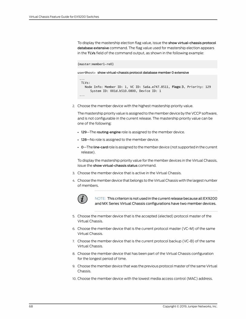
To display the mastership election flag value, issue the show virtual-chassis protocol
database extensive command. The flag value used for mastership election appears
in the TLVs field of the command output, as shown in the following example:
{master:member1-re0}
user@host> show virtual-chassis protocol databasemember 0 extensive
... TLVs: Node Info: Member ID: 1, VC ID: 5a6a.e747.8511, Flags: 3, Priority: 129 System ID: 001d.b510.0800, Device ID: 1 ...
2. Choose themember device with the highest mastership priority value.
Themastership priority value is assigned to themember deviceby theVCCPsoftware,
and is not configurable in the current release. Themastership priority value can be
one of the following:
• 129—The routing-engine role is assigned to the member device.
• 128—No role is assigned to the member device.
• 0—The line-card role is assigned to thememberdevice (not supported in thecurrent
release).
To display themastership priority value for themember devices in the Virtual Chassis,
issue the show virtual-chassis status command.
3. Choose themember device that is active in the Virtual Chassis.
4. Choose thememberdevice thatbelongs to theVirtualChassiswith the largestnumber
of members.
NOTE: This criterion is notused in thecurrent releasebecauseall EX9200andMX Series Virtual Chassis configurations have twomember devices.
5. Choose themember device that is the accepted (elected) protocol master of the
Virtual Chassis.
6. Choose themember device that is the current protocol master (VC-M) of the same
Virtual Chassis.
7. Choose themember device that is the current protocol backup (VC-B) of the same
Virtual Chassis.
8. Choose themember device that has been part of the Virtual Chassis configuration
for the longest period of time.
9. Choose themember device thatwas theprevious protocolmaster of the sameVirtual
Chassis.
10. Choose themember device with the lowest media access control (MAC) address.
Copyright © 2019, Juniper Networks, Inc.68
Virtual Chassis Feature Guide for EX9200 Switches
RelatedDocumentation
Virtual Chassis Components Overview•
• Global Roles and Local Roles in a Virtual Chassis on page 69
• Switching the Global Master and Backup Roles in a Virtual Chassis Configuration on
page 71
Global Roles and Local Roles in a Virtual Chassis
In aVirtualChassis configuration forMXSeries5GUniversalRoutingPlatformsorEX9200
switches, each of the twomember devices and each of the two Routing Engines in each
member device has a distinct role. A global role defines the function of eachmember
device in theVirtual Chassis, andapplies globally across theentireVirtual Chassis. A local
roledefines the functionofeachRoutingEngine in thememberdevice, andapplies locally
only to that member device.
Global roles change when you switch the Virtual Chassis mastership, and both global
roles and local roles change when you switch the Routing Engine mastership in one of
the member devices. In addition, the line-card global role, though not supported in a
preprovisioned configuration for a two-member MX Series or EX9200 Virtual Chassis,
applies in the context of split detection behavior.
This topic describes the global roles and local roles in a MX Series or EX9200 Virtual
Chassis so you can better understand how the Virtual Chassis behaves during a global
mastership switch, a local Routing Engine switchover, or when split detection is enabled.
• Role Name Format on page 69
• Global Role and Local Role Descriptions on page 70
Role Name Format
The global and local role names in an MX Series or EX9200 Virtual Chassis use the
following format:
VC-GlobalRole<LocalRole>
where:
• GlobalRole applies to the global function of the member device for the entire Virtual
Chassis, and can be one of the following:
• M—Virtual Chassis master device, also referred to as the protocol master.
• B—Virtual Chassis backup device, also referred to as the protocol backup.
• L—Virtual Chassis line-card device. The line-card role is not supported in the
preprovisioned configuration for a two-member Virtual Chassis. The line-card role
applies only in the context of split detection behavior.
• LocalRole (optional) applies to the function of the Routing Engine in the localmember
device, and can be one of the following:
• m—Master Routing Engine
69Copyright © 2019, Juniper Networks, Inc.
Chapter 7: Global Roles and Local Roles that Determine Mastership and Switchover Behavior
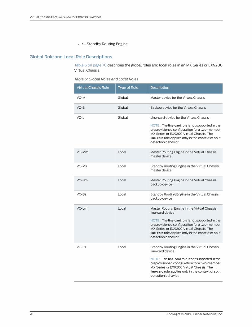
• s—Standby Routing Engine
Global Role and Local Role Descriptions
Table 6 on page 70 describes the global roles and local roles in an MX Series or EX9200
Virtual Chassis.
Table 6: Global Roles and Local Roles
DescriptionType of RoleVirtual Chassis Role
Master device for the Virtual ChassisGlobalVC-M
Backup device for the Virtual ChassisGlobalVC-B
Line-card device for the Virtual Chassis
NOTE: The line-card role is not supported in thepreprovisionedconfiguration for a two-memberMX Series or EX9200 Virtual Chassis. Theline-card role applies only in the context of splitdetection behavior.
GlobalVC-L
Master Routing Engine in the Virtual Chassismaster device
LocalVC-Mm
Standby Routing Engine in the Virtual Chassismaster device
LocalVC-Ms
Master Routing Engine in the Virtual Chassisbackup device
LocalVC-Bm
Standby Routing Engine in the Virtual Chassisbackup device
LocalVC-Bs
Master Routing Engine in the Virtual Chassisline-card device
NOTE: The line-card role is not supported in thepreprovisionedconfiguration for a two-memberMX Series or EX9200 Virtual Chassis. Theline-card role applies only in the context of splitdetection behavior.
LocalVC-Lm
Standby Routing Engine in the Virtual Chassisline-card device
NOTE: The line-card role is not supported in thepreprovisionedconfiguration for a two-memberMX Series or EX9200 Virtual Chassis. Theline-card role applies only in the context of splitdetection behavior.
LocalVC-Ls
Copyright © 2019, Juniper Networks, Inc.70
Virtual Chassis Feature Guide for EX9200 Switches
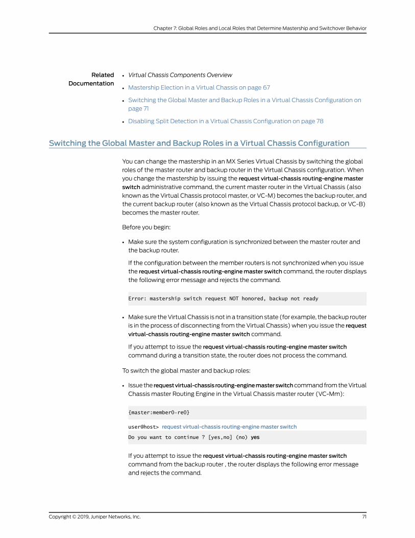
RelatedDocumentation
Virtual Chassis Components Overview•
• Mastership Election in a Virtual Chassis on page 67
• Switching the Global Master and Backup Roles in a Virtual Chassis Configuration on
page 71
• Disabling Split Detection in a Virtual Chassis Configuration on page 78
Switching the Global Master and Backup Roles in a Virtual Chassis Configuration
You can change themastership in an MX Series Virtual Chassis by switching the global
roles of the master router and backup router in the Virtual Chassis configuration. When
you change themastership by issuing the request virtual-chassis routing-enginemaster
switch administrative command, the current master router in the Virtual Chassis (also
known as the Virtual Chassis protocolmaster, or VC-M) becomes the backup router, and
the current backup router (also known as the Virtual Chassis protocol backup, or VC-B)
becomes themaster router.
Before you begin:
• Make sure the system configuration is synchronized between themaster router and
the backup router.
If the configuration between themember routers is not synchronized when you issue
the request virtual-chassis routing-enginemaster switch command, the router displays
the following error message and rejects the command.
Error: mastership switch request NOT honored, backup not ready
• Makesure theVirtualChassis is not in a transition state (for example, thebackup router
is in the process of disconnecting from the Virtual Chassis) when you issue the request
virtual-chassis routing-enginemaster switch command.
If you attempt to issue the request virtual-chassis routing-enginemaster switch
command during a transition state, the router does not process the command.
To switch the global master and backup roles:
• Issue the requestvirtual-chassis routing-enginemasterswitchcommandfromtheVirtual
Chassis master Routing Engine in the Virtual Chassis master router (VC-Mm):
{master:member0-re0}
user@host> request virtual-chassis routing-enginemaster switch
Do you want to continue ? [yes,no] (no) yes
If you attempt to issue the request virtual-chassis routing-enginemaster switch
command from the backup router , the router displays the following error message
and rejects the command.
71Copyright © 2019, Juniper Networks, Inc.
Chapter 7: Global Roles and Local Roles that Determine Mastership and Switchover Behavior
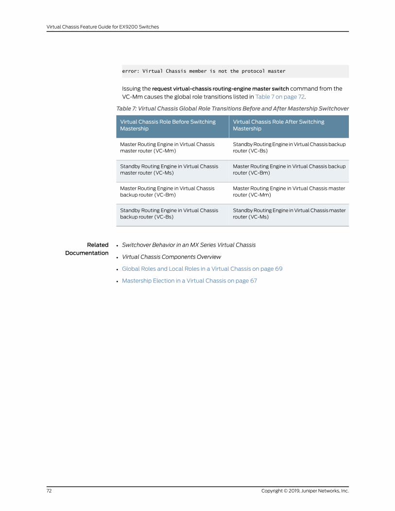
error: Virtual Chassis member is not the protocol master
Issuing the request virtual-chassis routing-enginemaster switch command from the
VC-Mm causes the global role transitions listed in Table 7 on page 72.
Table 7: Virtual Chassis Global Role Transitions Before and AfterMastership Switchover
Virtual Chassis Role After SwitchingMastership
Virtual Chassis Role Before SwitchingMastership
StandbyRoutingEngine inVirtualChassisbackuprouter (VC-Bs)
Master Routing Engine in Virtual Chassismaster router (VC-Mm)
Master Routing Engine in Virtual Chassis backuprouter (VC-Bm)
Standby Routing Engine in Virtual Chassismaster router (VC-Ms)
Master Routing Engine in Virtual Chassis masterrouter (VC-Mm)
Master Routing Engine in Virtual Chassisbackup router (VC-Bm)
StandbyRoutingEngine inVirtualChassismasterrouter (VC-Ms)
Standby Routing Engine in Virtual Chassisbackup router (VC-Bs)
RelatedDocumentation
• Switchover Behavior in an MX Series Virtual Chassis
• Virtual Chassis Components Overview
• Global Roles and Local Roles in a Virtual Chassis on page 69
• Mastership Election in a Virtual Chassis on page 67
Copyright © 2019, Juniper Networks, Inc.72
Virtual Chassis Feature Guide for EX9200 Switches

CHAPTER 8
MinimizingNetworkDisruptionUsingSplitDetection
• Split Detection Behavior in a Virtual Chassis on page 73
• Disabling Split Detection in a Virtual Chassis Configuration on page 78
Split Detection Behavior in a Virtual Chassis
If there is adisruption toaVirtualChassis configuration forMXSeries5GUniversalRouting
Platforms or EX9200 Switches due to the failure of a member router or switch or one or
more Virtual Chassis port interfaces, the resulting connectivity loss can cause a split in
the Virtual Chassis configuration. Split detection identifies the split and canminimize
further network disruption.
BEST PRACTICE: We recommend that you use the heartbeat connectioninstead of the split detection feature in anMXSeries Virtual Chassis to avoidunnecessarymastership role changesduringanadjacencydisruptionor split,and to provide additional member health information for themastershipelection process.
This topic covers:
• How Split DetectionWorks in a Virtual Chassis on page 73
• Effect of Split Detection on Virtual Chassis Failure Scenarios on page 74
HowSplit DetectionWorks in a Virtual Chassis
Split detection is enabledbydefault inanEX9200orMXSeriesVirtualChassis.Optionally,
you can disable split detection by including the no-split-detection statement at the [edit
virtual-chassis] hierarchy level. Disabling split detection can be useful in certain Virtual
Chassis configurations.
73Copyright © 2019, Juniper Networks, Inc.
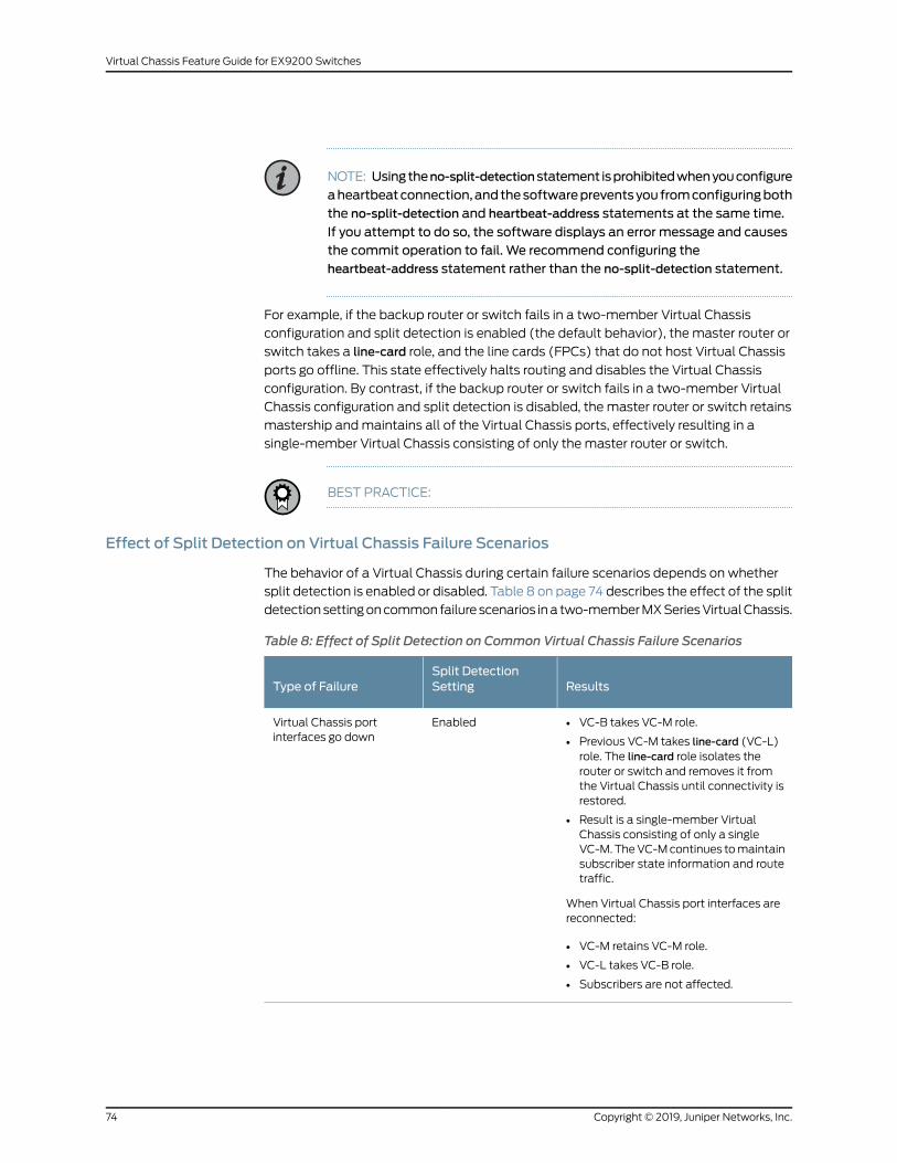
NOTE: Usingtheno-split-detectionstatement isprohibitedwhenyouconfigure
aheartbeatconnection,andthesoftwarepreventsyou fromconfiguringboththe no-split-detection and heartbeat-address statements at the same time.
If you attempt to do so, the software displays an error message and causesthe commit operation to fail. We recommend configuring theheartbeat-address statement rather than the no-split-detection statement.
For example, if the backup router or switch fails in a two-member Virtual Chassis
configuration and split detection is enabled (the default behavior), the master router or
switch takes a line-card role, and the line cards (FPCs) that do not host Virtual Chassis
ports go offline. This state effectively halts routing and disables the Virtual Chassis
configuration. By contrast, if the backup router or switch fails in a two-member Virtual
Chassis configuration and split detection is disabled, the master router or switch retains
mastership andmaintains all of the Virtual Chassis ports, effectively resulting in a
single-member Virtual Chassis consisting of only the master router or switch.
BEST PRACTICE:
Effect of Split Detection on Virtual Chassis Failure Scenarios
The behavior of a Virtual Chassis during certain failure scenarios depends on whether
split detection is enabled or disabled. Table 8 on page 74 describes the effect of the split
detectionsettingoncommonfailurescenarios ina two-memberMXSeriesVirtualChassis.
Table 8: Effect of Split Detection on Common Virtual Chassis Failure Scenarios
ResultsSplit DetectionSettingType of Failure
• VC-B takes VC-M role.
• Previous VC-M takes line-card (VC-L)role. The line-card role isolates therouter or switch and removes it fromthe Virtual Chassis until connectivity isrestored.
• Result is a single-member VirtualChassis consisting of only a singleVC-M.TheVC-Mcontinues tomaintainsubscriber state information and routetraffic.
When Virtual Chassis port interfaces arereconnected:
• VC-M retains VC-M role.
• VC-L takes VC-B role.
• Subscribers are not affected.
EnabledVirtual Chassis portinterfaces go down
Copyright © 2019, Juniper Networks, Inc.74
Virtual Chassis Feature Guide for EX9200 Switches
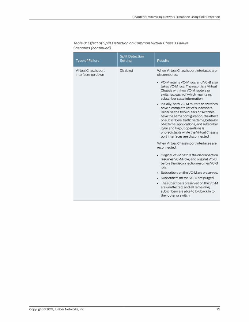
Table 8: Effect of Split Detection on Common Virtual Chassis FailureScenarios (continued)
ResultsSplit DetectionSettingType of Failure
When Virtual Chassis port interfaces aredisconnected:
• VC-M retains VC-M role, and VC-B alsotakes VC-M role. The result is a VirtualChassis with two VC-M routers orswitches, each of which maintainssubscriber state information.
• Initially, both VC-M routers or switcheshave a complete list of subscribers.Because the two routers or switcheshave the sameconfiguration, theeffectonsubscribers, trafficpatterns,behaviorof external applications, andsubscriberlogin and logout operations isunpredictablewhile theVirtual Chassisport interfaces are disconnected.
When Virtual Chassis port interfaces arereconnected:
• OriginalVC-Mbefore thedisconnectionresumes VC-M role, and original VC-Bbefore thedisconnection resumesVC-Brole.
• Subscriberson theVC-Marepreserved.
• Subscribers on the VC-B are purged.
• Thesubscriberspreservedon theVC-Mare unaffected, and all remainingsubscribers are able to log back in tothe router or switch.
DisabledVirtual Chassis portinterfaces go down
75Copyright © 2019, Juniper Networks, Inc.
Chapter 8: Minimizing Network Disruption Using Split Detection
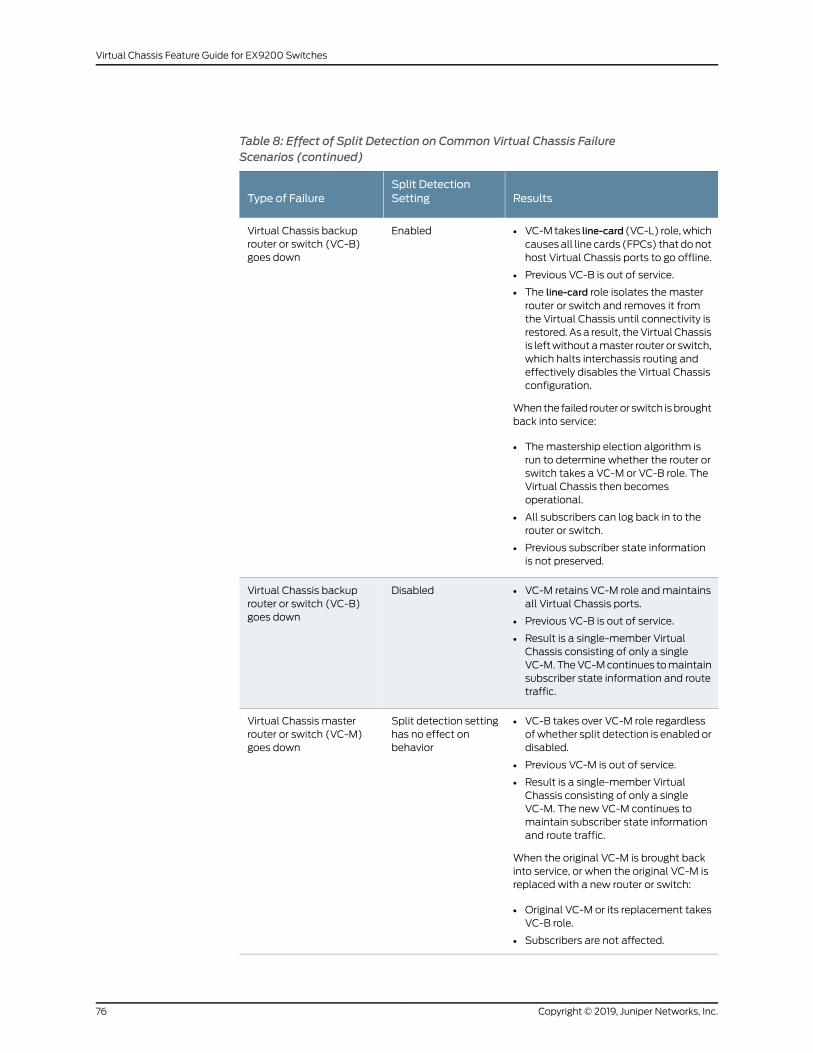
Table 8: Effect of Split Detection on Common Virtual Chassis FailureScenarios (continued)
ResultsSplit DetectionSettingType of Failure
• VC-Mtakes line-card (VC-L) role,whichcausesall line cards (FPCs) that donothost Virtual Chassis ports to go offline.
• Previous VC-B is out of service.
• The line-card role isolates the masterrouter or switch and removes it fromthe Virtual Chassis until connectivity isrestored. Asa result, theVirtualChassisis leftwithout amaster router or switch,which halts interchassis routing andeffectively disables the Virtual Chassisconfiguration.
When the failed router or switch isbroughtback into service:
• Themastership election algorithm isrun to determine whether the router orswitch takes a VC-M or VC-B role. TheVirtual Chassis then becomesoperational.
• All subscribers can log back in to therouter or switch.
• Previous subscriber state informationis not preserved.
EnabledVirtual Chassis backuprouter or switch (VC-B)goes down
• VC-M retains VC-M role andmaintainsall Virtual Chassis ports.
• Previous VC-B is out of service.
• Result is a single-member VirtualChassis consisting of only a singleVC-M.TheVC-Mcontinues tomaintainsubscriber state information and routetraffic.
DisabledVirtual Chassis backuprouter or switch (VC-B)goes down
• VC-B takes over VC-M role regardlessofwhether split detection is enabled ordisabled.
• Previous VC-M is out of service.
• Result is a single-member VirtualChassis consisting of only a singleVC-M. The new VC-M continues tomaintain subscriber state informationand route traffic.
When the original VC-M is brought backinto service, or when the original VC-M isreplaced with a new router or switch:
• Original VC-M or its replacement takesVC-B role.
• Subscribers are not affected.
Split detection settinghas no effect onbehavior
Virtual Chassis masterrouter or switch (VC-M)goes down
Copyright © 2019, Juniper Networks, Inc.76
Virtual Chassis Feature Guide for EX9200 Switches
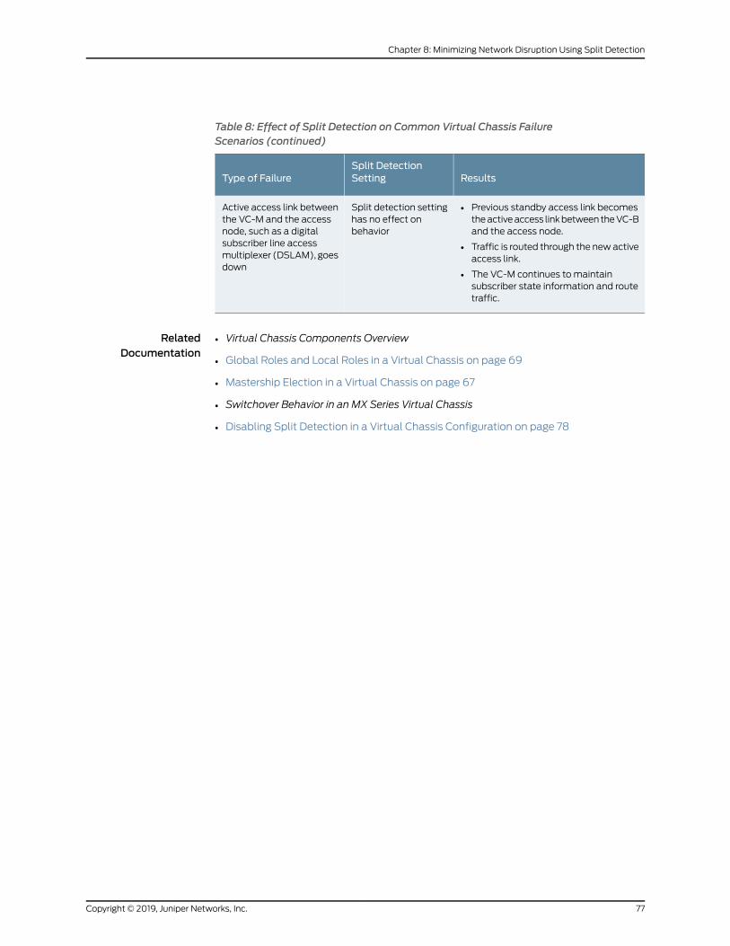
Table 8: Effect of Split Detection on Common Virtual Chassis FailureScenarios (continued)
ResultsSplit DetectionSettingType of Failure
• Previous standby access link becomestheactiveaccess linkbetween theVC-Band the access node.
• Traffic is routed through the newactiveaccess link.
• The VC-M continues to maintainsubscriber state information and routetraffic.
Split detection settinghas no effect onbehavior
Active access link betweenthe VC-M and the accessnode, such as a digitalsubscriber line accessmultiplexer (DSLAM), goesdown
RelatedDocumentation
Virtual Chassis Components Overview•
• Global Roles and Local Roles in a Virtual Chassis on page 69
• Mastership Election in a Virtual Chassis on page 67
• Switchover Behavior in an MX Series Virtual Chassis
• Disabling Split Detection in a Virtual Chassis Configuration on page 78
77Copyright © 2019, Juniper Networks, Inc.
Chapter 8: Minimizing Network Disruption Using Split Detection
Disabling Split Detection in a Virtual Chassis Configuration
If there is a disruption to a Virtual Chassis due to failure of a member device or one or
more Virtual Chassis port links, the resulting connectivity loss can cause a split in the
Virtual Chassis configuration. Split detection, which is enabled by default in anMXSeries
andEX9200VirtualChassis, identifies the split andminimizes further networkdisruption.
You can disable split detection by including the no-split-detection statement at the [edit
virtual-chassis] hierarchy level. Disabling split detection can be useful in certain Virtual
Chassis configurations.
For example, if the backup device fails in a two-member Virtual Chassis configuration
and split detection is enabled (the default behavior), themaster device takes a line-card
role, and the line cards (FPCs) that do not host Virtual Chassis ports go offline. This state
effectively isolates the master router or switch and removes it from the Virtual Chassis
until connectivity is restored. As a result, routing or switching is halted and the Virtual
Chassis configuration is disabled. By contrast, if the backup router or switch fails in a
two-member Virtual Chassis configuration and split detection is disabled, the master
router or switch retains mastership andmaintains all of the Virtual Chassis ports,
effectively resulting in a single-member Virtual Chassis consisting of only the master
device.
BEST PRACTICE: We recommend that you disable split detection for atwo-member Virtual Chassis configuration if you think the backup router orswitch is more likely to fail than the Virtual Chassis port interfaces to thebackup router or switch. Configuring redundant Virtual Chassis ports ondifferent line cards in eachmember router or switch reduces the likelihoodthat all Virtual Chassis port interfaces to the backup router or switch can fail.
To disable split detection:
1. Specify that you want to disable the default detection of splits in the Virtual Chassis.
[edit virtual-chassis]user@host# set no-split-detection
2. Commit the configuration.
Disabling split detection causes different results for different types of Virtual Chassis
failures. For information, see “Split Detection Behavior in a Virtual Chassis” on page 73.
RelatedDocumentation
• Split Detection Behavior in a Virtual Chassis on page 73
• Global Roles and Local Roles in a Virtual Chassis on page 69
• Switchover Behavior in an MX Series Virtual Chassis
• Virtual Chassis Components Overview
Copyright © 2019, Juniper Networks, Inc.78
Virtual Chassis Feature Guide for EX9200 Switches
PART 2
Troubleshooting
• Acquiring Troubleshooting Information on page 81
79Copyright © 2019, Juniper Networks, Inc.

Copyright © 2019, Juniper Networks, Inc.80
Virtual Chassis Feature Guide for EX9200 Switches
CHAPTER 9
Acquiring Troubleshooting Information
• Configuring the Name of the Virtual Chassis Trace Log File on page 81
• Configuring Characteristics of the Virtual Chassis Trace Log File on page 82
• Configuring Access to the Virtual Chassis Trace Log File on page 83
• Using Regular Expressions to Refine the Output of the Virtual Chassis Trace Log
File on page 84
• Configuring the Virtual Chassis Operations to Trace on page 85
• traceoptions (Virtual Chassis) on page 87
Configuring the Name of the Virtual Chassis Trace Log File
To trace operations for a Virtual Chassis, youmust configure the name of the trace log
file that the software saves in the /var/log directory.
To configure the filename for tracing Virtual Chassis operations:
• On the device to be designated as themaster of the Virtual Chassis, specify the name
of the trace log file.
[edit virtual-chassis]user@host# set traceoptions file filename
RelatedDocumentation
Tracing Virtual Chassis Operations for MX Series 3D Universal Edge Routers•
• Configuring Preprovisioned Member Information for a Virtual Chassis
• Example: Configuring Interchassis Redundancy for MX Series 3D Universal Edge Routers
Using a Virtual Chassis
81Copyright © 2019, Juniper Networks, Inc.
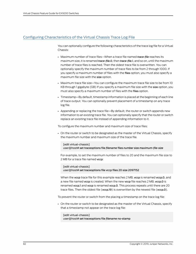
Configuring Characteristics of the Virtual Chassis Trace Log File
You can optionally configure the following characteristics of the trace log file for a Virtual
Chassis:
• Maximum number of trace files—When a trace file named trace-file reaches its
maximumsize, it is renamed trace-file.0, then trace-file.1, and so on, until themaximum
number of trace files is reached. Then the oldest trace file is overwritten. You can
optionally specify the maximum number of trace files to be from 2 through 1000. If
you specify a maximum number of files with the files option, youmust also specify a
maximum file size with the size option.
• Maximum trace file size—You can configure the maximum trace file size to be from 10
KB through 1 gigabyte (GB) If you specify amaximum file size with the size option, you
must also specify a maximum number of files with the files option.
• Timestamp—Bydefault, timestamp information is placed at the beginning of each line
of trace output. You can optionally prevent placement of a timestamp on any trace
log file.
• Appending or replacing the trace file—By default, the router or switch appends new
information to an existing trace file. You can optionally specify that the router or switch
replace an exisiting trace file instead of appending information to it.
To configure the maximum number andmaximum size of trace files:
• On the router or switch to be designated as the master of the Virtual Chassis, specify
the maximum number andmaximum size of the trace file.
[edit virtual-chassis]user@host# set traceoptions file filename files number sizemaximum-file-size
For example, to set the maximum number of files to 20 and themaximum file size to
2 MB for a trace file named vccp:
[edit virtual-chassis]user@host# set traceoptions file vccp files 20 size 2097152
When the vccp trace file for this example reaches 2 MB, vccp is renamed vccp.0, and
a new file named vccp is created. When the new vccp file reaches 2 MB, vccp.0 is
renamed vccp.1 and vccp is renamed vccp.0. This process repeats until there are 20
trace files. Then the oldest file (vccp.19) is overwritten by the newest file (vccp.0).
To prevent the router or switch from the placing a timestamp on the trace log file:
• On the router or switch to be designated as the master of the Virtual Chassis, specify
that a timestamp not appear on the trace log file:
[edit virtual-chassis]user@host# set traceoptions file filename no-stamp
Copyright © 2019, Juniper Networks, Inc.82
Virtual Chassis Feature Guide for EX9200 Switches
To replace an exisiting trace file instead of appending information to it:
• On the router or switch to be designated as the master of the Virtual Chassis, specify
that the router or switch replaces an existing trace file:
[edit virtual-chassis]user@host# set traceoptions file filename replace
RelatedDocumentation
Tracing Virtual Chassis Operations for MX Series 3D Universal Edge Routers•
• Configuring Preprovisioned Member Information for a Virtual Chassis
• Example: Configuring Interchassis Redundancy for MX Series 3D Universal Edge Routers
Using a Virtual Chassis
Configuring Access to the Virtual Chassis Trace Log File
By default, only the user who configures the tracing operation can access the log files.
You canenable all users to read the log file, and you canexplicitly set thedefault behavior
of the log file.
To configure access to the trace log file for all users:
• On the router or switch to be designated as the master of the Virtual Chassis, specify
that all users can read the trace log file.
[edit virtual-chassis]user@host# set traceoptions file filenameworld-readable
To explicitly set the default behavior to enable access to the trace log file only for the
user who configured tracing:
• On the router or switch to be designated as the master of the Virtual Chassis, specify
that only the user who configured tracing can read the trace log file.
[edit virtual-chassis]user@host# set traceoptions file filename no-world-readable
RelatedDocumentation
Tracing Virtual Chassis Operations for MX Series 3D Universal Edge Routers•
• Configuring Preprovisioned Member Information for a Virtual Chassis
• Example: Configuring Interchassis Redundancy for MX Series 3D Universal Edge Routers
Using a Virtual Chassis
83Copyright © 2019, Juniper Networks, Inc.
Chapter 9: Acquiring Troubleshooting Information
Using Regular Expressions to Refine the Output of the Virtual Chassis Trace Log File
By default, the trace operation output includes all lines relevant to the logged events.
You can refine the output of the trace log file for a Virtual Chassis by including regular
expressions to bematched.
To refine the output of the trace log file:
• On the router or switch to be designated as themaster of theVirtual Chassis, configure
a regular expression to bematched.
[edit virtual-chassis]user@host# set traceoptions file filenamematch regular-expression
RelatedDocumentation
Tracing Virtual Chassis Operations for MX Series 3D Universal Edge Routers•
• Configuring Preprovisioned Member Information for a Virtual Chassis
• Example: Configuring Interchassis Redundancy for MX Series 3D Universal Edge Routers
Using a Virtual Chassis
Copyright © 2019, Juniper Networks, Inc.84
Virtual Chassis Feature Guide for EX9200 Switches
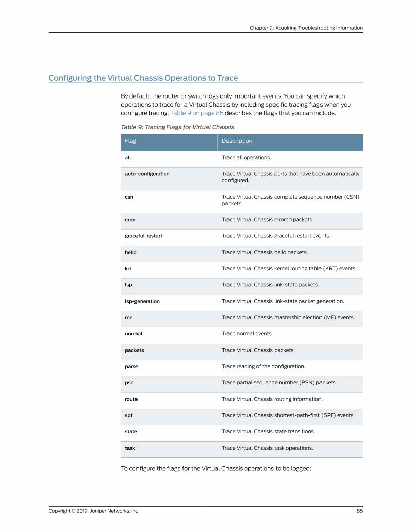
Configuring the Virtual Chassis Operations to Trace
By default, the router or switch logs only important events. You can specify which
operations to trace for a Virtual Chassis by including specific tracing flags when you
configure tracing. Table 9 on page 85 describes the flags that you can include.
Table 9: Tracing Flags for Virtual Chassis
DescriptionFlag
Trace all operations.all
Trace Virtual Chassis ports that have been automaticallyconfigured.
auto-configuration
Trace Virtual Chassis complete sequence number (CSN)packets.
csn
Trace Virtual Chassis errored packets.error
Trace Virtual Chassis graceful restart events.graceful-restart
Trace Virtual Chassis hello packets.hello
Trace Virtual Chassis kernel routing table (KRT) events.krt
Trace Virtual Chassis link-state packets.lsp
Trace Virtual Chassis link-state packet generation.lsp-generation
Trace Virtual Chassis mastership election (ME) events.me
Trace normal events.normal
Trace Virtual Chassis packets.packets
Trace reading of the configuration.parse
Trace partial sequence number (PSN) packets.psn
Trace Virtual Chassis routing information.route
Trace Virtual Chassis shortest-path-first (SPF) events.spf
Trace Virtual Chassis state transitions.state
Trace Virtual Chassis task operations.task
To configure the flags for the Virtual Chassis operations to be logged:
85Copyright © 2019, Juniper Networks, Inc.
Chapter 9: Acquiring Troubleshooting Information
1. Specify the tracing flag that represents the operation you want to trace.
[edit virtual-chassis]user@host# set traceoptions flag flag
2. (Optional) Specify one or more of the following additional tracing options for the
specified flag:
• To generate detailed trace output, use the detail option.
• To disable a particular flag, use the disable option.
• To trace received packets, use the receive option.
• To trace transmitted packets, use the send option.
For example, to generate detailed trace output for Virtual Chassismastership election
events in received packets:
[edit virtual-chassis]user@host# set traceoptions flagme detail receive
RelatedDocumentation
Tracing Virtual Chassis Operations for MX Series 3D Universal Edge Routers•
• Configuring Preprovisioned Member Information for a Virtual Chassis
• Example: Configuring Interchassis Redundancy for MX Series 3D Universal Edge Routers
Using a Virtual Chassis
Copyright © 2019, Juniper Networks, Inc.86
Virtual Chassis Feature Guide for EX9200 Switches
traceoptions (Virtual Chassis)
Syntax traceoptions {file filename <files number> <no-stamp> <replace> <size size> <world-readable |no-world-readable>;
flag flag <detail> <disable> <receive> <send>;}
Hierarchy Level [edit virtual-chassis]
Release Information Statement introduced in Junos OS Release 9.0 for EX Series switches.
Option detail added in Junos OS Release 9.2 for EX Series switches.
Statement introduced in Junos OS Release 13.2X50-D15 for the QFX Series.
Statement introduced in JunosOSRelease 13.2X51-D20 for Virtual Chassis Fabric (VCF).
Description Define tracing operations for the Virtual Chassis or VCF.
Each Virtual Chassis or VCFmember is updatedwith configured tracing options, and the
log file is stored locally on each device.
NOTE: In a large-scale VCF, use system logging and tracing with discretion,and only for troubleshooting. These operations place an extra load on themaster Routing Engine device, which can impact VCF convergence time andstability. All tracing options should bedisabledduring normalVCFoperation.To troubleshoot particular problems, selectively enable tracing options, anddisable them again after collecting the desired information.
Default Tracing operations are disabled.
Options detail—(Optional) Generate detailed trace information for a flag.
NOTE: Enable tracingat thedetail levelonlywhile troubleshootingaparticularissue, and disable it again for normal system operation.
disable—(Optional) Disable a flag.
file filename—Name of the file to receive the output of the tracing operation. Enclose the
namewithin quotation marks. All files are placed in the directory /var/log.
files number—(Optional) Maximum number of trace files. When a trace file named
trace-file reaches its maximum size, it is renamed trace-file.0, then trace-file.1, and
so on, until themaximum number of trace files is reached. Then the oldest trace file
87Copyright © 2019, Juniper Networks, Inc.
Chapter 9: Acquiring Troubleshooting Information
is overwritten. If you specify a maximum number of files, you also must specify a
maximum file size with the size option.
Range: 2 through 1000
Default: 3 files
flag flag—Tracing operation to perform. To specify more than one tracing operation,
includemultiple flag statements. You can include the following flags:
• all—All tracing operations.
TIP: The all flag displays a subset of logs that are generally useful in
debugging issues, and for more detailed information, you can use optionsall detail. However, to avoid significantly impacting VCF stability, use this
high level of tracing only for troubleshooting for a short period of time, andnot during normal VCF operation.
• auto-configuration—Trace Virtual Chassis ports (VCPs) that have been automatically
configured.
• csn—Trace Virtual Chassis complete sequence number (CSN) packets.
• error—Trace Virtual Chassis errored packets.
• hello—Trace Virtual Chassis hello packets.
• krt—Trace Virtual Chassis KRT events.
• lsp—Trace Virtual Chassis link-state packets.
• lsp-generation—Trace Virtual Chassis link-state packet generation.
• me—Trace Virtual Chassis ME events.
• normal—Trace normal events.
• packets—Trace Virtual Chassis packets.
• parse—Trace reading of the configuration.
• psn—Trace partial sequence number (PSN) packets.
• route—Trace Virtual Chassis routing information.
• spf—Trace Virtual Chassis SPF events.
• state—Trace Virtual Chassis state transitions.
• task—Trace Virtual Chassis task operations.
no-stamp—(Optional) Do not place a timestamp on any trace file.
no-world-readable—(Optional) Restrict file access to the user who created the file.
receive—(Optional) Trace received packets.
replace—(Optional) Replace a trace file rather than appending information to it.
Copyright © 2019, Juniper Networks, Inc.88
Virtual Chassis Feature Guide for EX9200 Switches
send—(Optional) Trace transmitted packets.
size size—(Optional)Maximumsize of each trace file, in kilobytes (KB),megabytes (MB),
or gigabytes (GB). When a trace file named trace-file reaches its maximum size, it is
renamed trace-file.0, then trace-file.1, and so on, until themaximumnumber of trace
files is reached. Then the oldest trace file is overwritten. If you specify a maximum
number of files, you also must specify a maximum file size with the files option.
Syntax: xk to specify KB, xm to specify MB, or xg to specify GB
Range: 10 KB through 1 GB
Default: 128 KB
world-readable—(Optional) Enable unrestricted file access.
Required PrivilegeLevel
system—To view this statement in the configuration.
system-control—To add this statement to the configuration.
RelatedDocumentation
• Monitoring the Virtual Chassis Status and Statistics on EX Series Virtual Chassis
• Verifying the Member ID, Role, and Neighbor Member Connections of a Virtual Chassis
Member
• Verifying That Virtual Chassis Ports Are Operational
• Troubleshooting an EX Series Virtual Chassis
• Troubleshooting Virtual Chassis Fabric
89Copyright © 2019, Juniper Networks, Inc.
Chapter 9: Acquiring Troubleshooting Information

Copyright © 2019, Juniper Networks, Inc.90
Virtual Chassis Feature Guide for EX9200 Switches
PART 3
Routine Monitoring
• Monitoring a Virtual Chassis on page 93
91Copyright © 2019, Juniper Networks, Inc.

Copyright © 2019, Juniper Networks, Inc.92
Virtual Chassis Feature Guide for EX9200 Switches
CHAPTER 10
Monitoring a Virtual Chassis
• Verifying the Status of Virtual Chassis Member Routers or Switches on page 93
• Verifying Neighbor Reachability for Member Routers or Switches in a Virtual
Chassis on page 93
• Verifying Neighbor Reachability for Hardware Devices in a Virtual Chassis on page 94
• Viewing Information in the Virtual Chassis Control Protocol Adjacency
Database on page 95
• Viewing Information in the Virtual Chassis Control Protocol Link-State
Database on page 95
• Viewing InformationAboutVirtualChassisPort Interfaces in theVirtualChassisControl
Protocol Database on page 96
• Viewing Virtual Chassis Control Protocol Statistics for Member Devices and Virtual
Chassis Ports on page 97
Verifying the Status of Virtual Chassis Member Routers or Switches
Purpose Verify that the member routers or switches in an MX Series or EX9200 Virtual Chassis
are properly configured.
Action Display the status of the members of the Virtual Chassis configuration:
user@host> show virtual-chassis status
RelatedDocumentation
Configuring Interchassis Redundancy for MX Series 3D Universal Edge Routers Using a
Virtual Chassis
•
• Configuring an EX9200 Virtual Chassis on page 38
• Example: Configuring Interchassis Redundancy for MX Series 3D Universal Edge Routers
Using a Virtual Chassis
Verifying Neighbor Reachability for Member Routers or Switches in a Virtual Chassis
Purpose Verify that eachmember router or switch in an MX Series or EX9200 Virtual Chassis has
a path to reach the neighbor devices to which it is connected.
93Copyright © 2019, Juniper Networks, Inc.

Action To display neighbor reachability information for both member devices in the Virtual
Chassis:
•
user@host> show virtual-chassis active-topology all-members
• Todisplayneighbor reachability information for a specifiedmemberdevice in theVirtual
Chassis:
user@host> show virtual-chassis active-topologymembermember-id
• To display neighbor reachability information for the member device on which you are
issuing the command:
user@host> show virtual-chassis active-topology local
RelatedDocumentation
Configuring Interchassis Redundancy for MX Series 3D Universal Edge Routers Using a
Virtual Chassis
•
• Configuring an EX9200 Virtual Chassis on page 38
• Example: Configuring Interchassis Redundancy for MX Series 3D Universal Edge Routers
Using a Virtual Chassis
Verifying Neighbor Reachability for Hardware Devices in a Virtual Chassis
Purpose Verify that each hardware device in an MX Series Virtual Chassis or an EX9200 Virtual
Chassis can reach the neighbor routers and devices to which it is connected. On the MX
Series routing platform, there is only one active device for eachmember router.
Action To display neighbor reachability information for the devices in both member routers
in the Virtual Chassis:
•
user@host> show virtual-chassis device-topology all-members
• Todisplayneighbor reachability information for thedevice inaspecifiedmember router
in the Virtual Chassis:
user@host> show virtual-chassis device-topologymembermember-id
• To display neighbor reachability information for the device in the member router on
which you are issuing the command:
user@host> show virtual-chassis device-topology local
RelatedDocumentation
Configuring Interchassis Redundancy for MX Series 3D Universal Edge Routers Using a
Virtual Chassis
•
• Configuring an EX9200 Virtual Chassis on page 38
Copyright © 2019, Juniper Networks, Inc.94
Virtual Chassis Feature Guide for EX9200 Switches
• Example: Configuring Interchassis Redundancy for MX Series 3D Universal Edge Routers
Using a Virtual Chassis
Viewing Information in the Virtual Chassis Control Protocol Adjacency Database
Purpose View information about neighbors in the Virtual Chassis Control Protocol (VCCP)
adjacency database for a Virtual Chassis configuration.
Action TodisplayVCCPneighboradjacency information forbothmemberdevices in theVirtual
Chassis:
•
user@host> show virtual-chassis protocol adjacency all-members
• To display VCCP neighbor adjacency information for a specifiedmember device in the
Virtual Chassis:
user@host> show virtual-chassis protocol adjacencymembermember-id
• TodisplayVCCPneighbor adjacency information for thedevicewith a specified system
ID:
user@host> show virtual-chassis protocol adjacency system-id
• TodisplayVCCPneighbor adjacency information for thedevicewith a specified system
ID on the specified member router or switch:
user@host> show virtual-chassis protocol adjacencymembermember-id system-id
• To display VCCP neighbor adjacency information for themember device on which you
are issuing the command:
user@host> show virtual-chassis protocol adjacency local
RelatedDocumentation
Configuring Interchassis Redundancy for MX Series 3D Universal Edge Routers Using a
Virtual Chassis
•
• Configuring an EX9200 Virtual Chassis on page 38
• Example: Configuring Interchassis Redundancy for MX Series 3D Universal Edge Routers
Using a Virtual Chassis
Viewing Information in the Virtual Chassis Control Protocol Link-State Database
Purpose View information about protocol data unit (PDU) packets in the Virtual Chassis Control
Protocol (VCCP) link-state database for a Virtual Chassis configuration.
Action To display VCCP PDU information for both member routers or switches in the Virtual
Chassis:
•
95Copyright © 2019, Juniper Networks, Inc.
Chapter 10: Monitoring a Virtual Chassis
user@host> show virtual-chassis protocol database all-members
• TodisplayVCCPPDU information for a specifiedmember router or switch in theVirtual
Chassis:
user@host> show virtual-chassis protocol databasemembermember-id
• To display VCCP PDU information for the device with a specified system ID:
user@host> show virtual-chassis protocol database system-id
• To display VCCP PDU information for the device with a specified system ID on the
specified member router or switch:
user@host> show virtual-chassis protocol databasemembermember-id system-id
• To display VCCP PDU information for the member router or switch on which you are
issuing the command:
user@host> show virtual-chassis protocol database local
RelatedDocumentation
Configuring Interchassis Redundancy for MX Series 3D Universal Edge Routers Using a
Virtual Chassis
•
• Configuring an EX9200 Virtual Chassis on page 38
• Example: Configuring Interchassis Redundancy for MX Series 3D Universal Edge Routers
Using a Virtual Chassis
Viewing InformationAboutVirtualChassisPort Interfaces in theVirtualChassisControlProtocol Database
Purpose View information in the Virtual Chassis Control Protocol (VCCP) database about Virtual
Chassis port interfaces in the Virtual Chassis.
Action To display VCCP information about Virtual Chassis port interfaces for both member
routers or switches:
•
user@host> show virtual-chassis protocol interface all-members
• To display VCCP information about Virtual Chassis port interfaces for a specified
member router or switch:
user@host> show virtual-chassis protocol interfacemembermember-id
• To display VCCP information about a specified Virtual Chassis port interface:
user@host> show virtual-chassis protocol interface vcp-slot/pic/port.logical-unit-number
Copyright © 2019, Juniper Networks, Inc.96
Virtual Chassis Feature Guide for EX9200 Switches
• To display VCCP information about Virtual Chassis port interfaces for the member
router or switch on which you are issuing the command:
user@host> show virtual-chassis protocol interface local
RelatedDocumentation
Configuring Interchassis Redundancy for MX Series 3D Universal Edge Routers Using a
Virtual Chassis
•
• Configuring an EX9200 Virtual Chassis on page 38
• Example: Configuring Interchassis Redundancy for MX Series 3D Universal Edge Routers
Using a Virtual Chassis
Viewing Virtual Chassis Control Protocol Statistics for Member Devices and VirtualChassis Ports
Purpose View Virtual Chassis Control Protocol (VCCP) statistics for one or both member routers
or switches, or for a specified Virtual Chassis port interface, in a Virtual Chassis
configuration.
Action To display VCCP statistics for both member routers or switches in the Virtual Chassis:•
user@host> show virtual-chassis protocol statistics all-members
• TodisplayVCCPstatistics for a specifiedmember router or switch in theVirtualChassis:
user@host> show virtual-chassis protocol statisticsmembermember-id
• To display VCCP statistics for a specified Virtual Chassis port interface:
user@host> show virtual-chassis protocol statistics vcp-slot/pic/port.logical-unit-number
• To display VCCP statistics for the member router or switch on which you are issuing
the command:
user@host> show virtual-chassis protocol statistics local
RelatedDocumentation
• Configuring Interchassis Redundancy for MX Series 3D Universal Edge Routers Using a
Virtual Chassis
• Configuring an EX9200 Virtual Chassis on page 38
• Example: Configuring Interchassis Redundancy for MX Series 3D Universal Edge Routers
Using a Virtual Chassis
97Copyright © 2019, Juniper Networks, Inc.
Chapter 10: Monitoring a Virtual Chassis

Copyright © 2019, Juniper Networks, Inc.98
Virtual Chassis Feature Guide for EX9200 Switches
PART 4
Configuration Statements andOperational Commands
• Configuration Statements on page 101
• Operational Commands: Administrative on page 119
• Operational Commands: Monitoring on page 129
99Copyright © 2019, Juniper Networks, Inc.

Copyright © 2019, Juniper Networks, Inc.100
Virtual Chassis Feature Guide for EX9200 Switches
CHAPTER 11
Configuration Statements
• aggregated-ether-options on page 102
• logical-interface-fpc-redundancy (Aggregated Ethernet Subscriber
Interfaces) on page 105
• member on page 106
• no-split-detection on page 107
• preprovisioned on page 108
• role on page 109
• serial-number on page 112
• targeted-distribution (Static Interfaces over Aggregated Ethernet) on page 113
• traceoptions (Virtual Chassis) on page 114
• virtual-chassis on page 117
101Copyright © 2019, Juniper Networks, Inc.
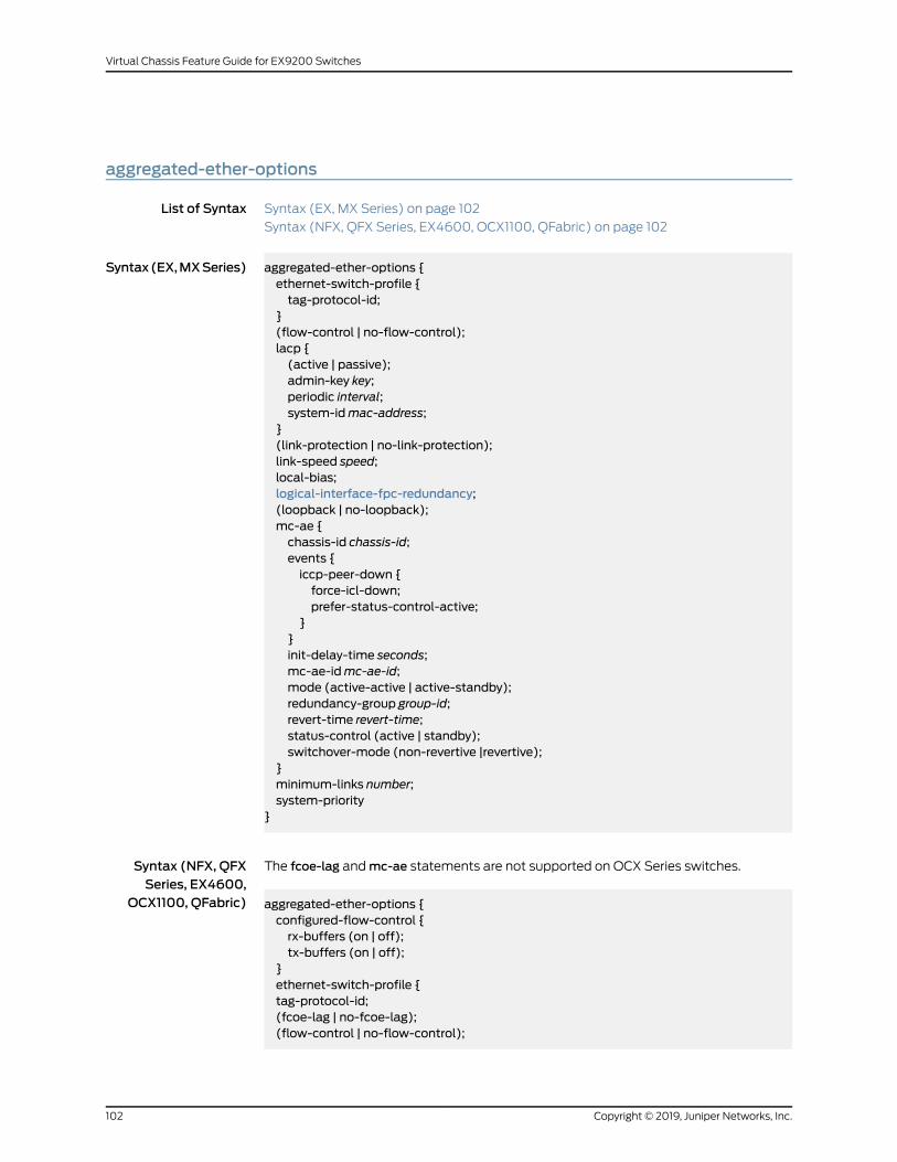
aggregated-ether-options
List of Syntax Syntax (EX, MX Series) on page 102
Syntax (NFX, QFX Series, EX4600, OCX1100, QFabric) on page 102
Syntax(EX,MXSeries) aggregated-ether-options {ethernet-switch-profile {tag-protocol-id;
}(flow-control | no-flow-control);lacp {(active | passive);admin-key key;periodic interval;system-idmac-address;
}(link-protection | no-link-protection);link-speed speed;local-bias;logical-interface-fpc-redundancy;(loopback | no-loopback);mc-ae {chassis-id chassis-id;events {iccp-peer-down {force-icl-down;prefer-status-control-active;
}}init-delay-time seconds;mc-ae-idmc-ae-id;mode (active-active | active-standby);redundancy-group group-id;revert-time revert-time;status-control (active | standby);switchover-mode (non-revertive |revertive);
}minimum-links number;system-priority
}
Syntax (NFX, QFXSeries, EX4600,
OCX1100, QFabric)
The fcoe-lag andmc-ae statements are not supported on OCX Series switches.
aggregated-ether-options {configured-flow-control {rx-buffers (on | off);tx-buffers (on | off);
}ethernet-switch-profile {tag-protocol-id;(fcoe-lag | no-fcoe-lag);(flow-control | no-flow-control);
Copyright © 2019, Juniper Networks, Inc.102
Virtual Chassis Feature Guide for EX9200 Switches
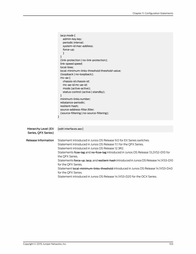
lacpmode {admin-key key;periodic interval;system-idmac-address;force-up;}
}(link-protection | no-link-protection);link-speed speed;local-bias;local-minimum-links-threshold threshold-value;(loopback | no-loopback);mc-ae {chassis-id chassis-id;mc-ae-idmc-ae-id;mode (active-active);status-control (active | standby);
}minimum-links number;rebalance-periodic;resilient-hash;source-address-filter filter;(source-filtering | no-source-filtering);
}
Hierarchy Level (EXSeries, QFX Series)
[edit interfaces aex]
Release Information Statement introduced in Junos OS Release 9.0 for EX Series switches.
Statement introduced in Junos OS Release 11.1 for the QFX Series.
Statement introduced in Junos OS Release 12.3R2.
Statements fcoe-lag and no-fcoe-lag introduced in Junos OS Release 13.2X52-D10 for
the QFX Series.
Statements force-up, lacp, and resilient-hash introduced in JunosOSRelease 14.1X53-D10
for the QFX Series.
Statement local-minimum-links-threshold introduced in Junos OS Release 14.1X53-D40
for the QFX Series.
Statement introduced in Junos OS Release 14.1X53-D20 for the OCX Series.
103Copyright © 2019, Juniper Networks, Inc.
Chapter 11: Configuration Statements
Description Configure theaggregatedEthernetpropertiesof a specific aggregatedEthernet interface.
NOTE:
• The fcoe-lag andmc-ae statements are not supported on OCX Series
switches.
• The force-up statement is not supported on QFX10002 switches.
• The resilient-hash statement is not supported on QFX10002 switches.
The remaining statements are explained separately. See CLI Explorer.
Default Options are not enabled.
Required PrivilegeLevel
interface—To view this statement in the configuration.
interface-control—To add this statement to the configuration.
RelatedDocumentation
• Understanding Aggregated Ethernet Interfaces and LACP for Switches
• Configuring Aggregated Ethernet LACP (CLI Procedure)
• Example: Configuring Link Aggregation with LACP Between aQFX Series Product and an
Aggregation Switch
• Junos OS Network Interfaces Library for Routing Devices
• Example: Configuring Aggregated Ethernet High-Speed Uplinks Between an EX4200
Virtual Chassis Access Switch and an EX4200 Virtual Chassis Distribution Switch
• Example: Configuring Aggregated Ethernet High-Speed Uplinks with LACP Between an
EX4200VirtualChassisAccessSwitchandanEX4200VirtualChassisDistributionSwitch
• Configuring Aggregated Ethernet Links (CLI Procedure)
• Configuring Aggregated Ethernet LACP (CLI Procedure)
• Configuring LACP Link Protection of Aggregated Ethernet Interfaces for Switches
• Configuring Q-in-Q Tunneling on EX Series Switches with ELS Support
• Junos OS Ethernet Interfaces Configuration Guide
Copyright © 2019, Juniper Networks, Inc.104
Virtual Chassis Feature Guide for EX9200 Switches
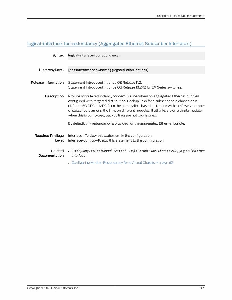
logical-interface-fpc-redundancy (Aggregated Ethernet Subscriber Interfaces)
Syntax logical-interface-fpc-redundancy;
Hierarchy Level [edit interfaces aenumber aggregated-ether-options]
Release Information Statement introduced in Junos OS Release 11.2.
Statement introduced in Junos OS Release 13.2R2 for EX Series switches.
Description Provide module redundancy for demux subscribers on aggregated Ethernet bundles
configured with targeted distribution. Backup links for a subscriber are chosen on a
different EQDPCorMPC from the primary link, based on the linkwith the fewest number
of subscribers among the links on different modules. If all links are on a single module
when this is configured, backup links are not provisioned.
By default, link redundancy is provided for the aggregated Ethernet bundle.
Required PrivilegeLevel
interface—To view this statement in the configuration.
interface-control—To add this statement to the configuration.
RelatedDocumentation
• ConfiguringLinkandModuleRedundancy forDemuxSubscribers inanAggregatedEthernet
Interface
• Configuring Module Redundancy for a Virtual Chassis on page 62
105Copyright © 2019, Juniper Networks, Inc.
Chapter 11: Configuration Statements
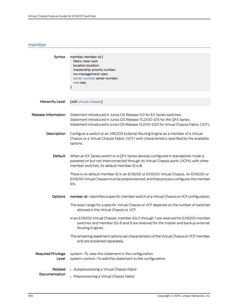
member
Syntax membermember-id {fabric-tree-root;location location;mastership-priority number;no-management-vlan;serial-number serial-number;role role;
}
Hierarchy Level [edit virtual-chassis]
Release Information Statement introduced in Junos OS Release 9.0 for EX Series switches.
Statement introduced in Junos OS Release 13.2X50-D15 for the QFX Series.
Statement introduced in JunosOSRelease 13.2X51-D20 for Virtual Chassis Fabric (VCF).
Description Configure a switch or an XRE200 External Routing Engine as amember of a Virtual
Chassis or a Virtual Chassis Fabric (VCF) with characteristics specified by the available
options.
Default When an EX Series switch or a QFX Series devices configured in standalonemode is
powered on but not interconnected through its Virtual Chassis ports (VCPs) with other
member switches, its default member ID is 0.
There is no default member ID in an EX8200 or EX9200 Virtual Chassis. An EX8200 or
EX9200VirtualChassismustbepreprovisioned, and thatprocessconfigures themember
IDs.
Options member-id—Identifiesaspecificmember switchofaVirtualChassisorVCFconfiguration.
The exact range for a specific Virtual Chassis or VCF depends on the number of switches
allowed in the Virtual Chassis or VCF.
In an EX8200Virtual Chassis,member IDs 0 through 7 are reserved for EX8200member
switches andmember IDs 8 and 9 are reserved for the master and backup external
Routing Engines.
The remainingstatementoptionssetcharacteristicsof theVirtualChassisorVCFmember,
and are explained separately.
Required PrivilegeLevel
system—To view this statement in the configuration.
system-control—To add this statement to the configuration.
RelatedDocumentation
Autoprovisioning a Virtual Chassis Fabric•
• Preprovisioning a Virtual Chassis Fabric
Copyright © 2019, Juniper Networks, Inc.106
Virtual Chassis Feature Guide for EX9200 Switches
• Adding a Device to a Virtual Chassis Fabric
• Configuring a QFX Series Virtual Chassis
• Configuring an EX2300, EX3400, or EX4300 Virtual Chassis
• Configuring EX4600 Switches in a Mixed or Non-Mixed Virtual Chassis
• Configuring an EX9200 Virtual Chassis on page 38
• Configuring a QFX Series Virtual Chassis
no-split-detection
Syntax no-split-detection;
Hierarchy Level [edit virtual-chassis]
Release Information Statement introduced in Junos OS Release 9.3 for EX Series switches.
Statement introduced in Junos OS Release 13.2X50-D15 for the QFX Series.
Statement introduced in JunosOSRelease 13.2X51-D20 for Virtual Chassis Fabric (VCF).
Description Disable the split andmerge feature in a Virtual Chassis or VCF configuration.
We recommend using this statement to disable the split andmerge feature when
configuring a two-member Virtual Chassis. Enabling this statement on a two-member
Virtual Chassis ensures that both switches remain in the correct Virtual Chassis roles in
the event of a Virtual Chassis split.
The split andmerge feature is enabled by default when a Virtual Chassis is initially set
up. If you set this option in a two-member Virtual Chassis and then expand the Virtual
Chassis to addmore members, we recommend deleting this configuration item to
re-enable the split andmerge feature again.
Default The split andmerge feature is enabled.
Required PrivilegeLevel
system—To view this statement in the configuration.
system-control—To add this statement to the configuration.
RelatedDocumentation
• Example: Assigning the Virtual Chassis ID to Determine Precedence During an EX4200
Virtual Chassis Merge
• Disabling Split and Merge in a Virtual Chassis
• Assigning the Virtual Chassis ID to Determine Precedence During a Virtual Chassis Merge
• Disabling Split Detection in a Virtual Chassis Configuration on page 78
• Understanding Split and Merge in a Virtual Chassis
107Copyright © 2019, Juniper Networks, Inc.
Chapter 11: Configuration Statements
preprovisioned
Syntax preprovisioned;
Hierarchy Level [edit virtual-chassis]
Release Information Statement introduced in Junos OS Release 9.0 for EX Series switches.
Statement introduced in Junos OS Release 13.2X50-D15 for the QFX Series.
Statement introduced in JunosOSRelease 13.2X51-D20 for Virtual Chassis Fabric (VCF).
Description Enable the preprovisioned configuration mode for a Virtual Chassis or Virtual Chassis
Fabric (VCF) configuration.
When the preprovisioned configuration mode is enabled, you cannot use the CLI or the
J-Web interface to change themastership priority or member ID of member switches.
Youmust use this statement to configure an EX8200 Virtual Chassis. Nonprovisioned
configuration of an EX8200 Virtual Chassis is not supported.
Required PrivilegeLevel
system—To view this statement in the configuration.
system-control—To add this statement to the configuration.
RelatedDocumentation
• Preprovisioning a Virtual Chassis Fabric
• Example: Configuring an EX4200 Virtual Chassis Using a Preprovisioned Configuration
File
• Example: Setting Up a Full Mesh EX8200 Virtual Chassis with Two EX8200 Switches
and Redundant XRE200 External Routing Engines
• Configuring an EX4200, EX4500, or EX4550 Virtual Chassis (CLI Procedure)
• Configuring an EX8200 Virtual Chassis (CLI Procedure)
• Configuring an EX9200 Virtual Chassis on page 38
• Configuring a QFX Series Virtual Chassis
• Removing or Replacing a Member Switch of a Virtual Chassis Configuration
Copyright © 2019, Juniper Networks, Inc.108
Virtual Chassis Feature Guide for EX9200 Switches
role
Syntax role (line-card | routing-engine);
Hierarchy Level [edit virtual-chassis membermember-id]
Release Information Statement introduced in Junos OS Release 9.0 for EX Series switches.
Statement introduced in Junos OS Release 13.2X50-D15 for the QFX Series.
Statement introduced in JunosOSRelease 13.2X51-D20 for Virtual Chassis Fabric (VCF).
Description Specify the roles of themembers of the Virtual Chassis or a Virtual Chassis Fabric (VCF)
in a preprovisionedVirtual Chassis. For amixedVirtual Chassis or VCF, seeUnderstanding
Mixed EX Series and QFX Series Virtual Chassis or Understanding Mixed Virtual Chassis
Fabric for any recommendations or requirements for assigning the Routing Engine role
based on the types of switches comprising the Virtual Chassis or VCF.
Virtual Chassis Fabric
Specify the role tobeperformedbyeachswitch. InaVCF, twospinedevicesare configured
into the Routing Engine role and the remaining spine devices and all leaf devices are
configured into the line-card role. The role must also be associated with the member’s
serial number (see serial-number).
EX Series (except EX8200 Virtual Chassis) and QFX Series Virtual Chassis
Specify the role to be performed by eachmember switch. Associate the role with the
member’s serial number (see serial-number).
When you use a preprovisioned configuration, you cannotmodify themastership priority
or member ID of member switches through the user interfaces. Themastership priority
value is generated by the software, based on the assigned role:
• Amember configured as routing-engine is assigned themastership priority 129.
• Amember configured as line-card is assigned themastership priority 0.
• Amember listed in the preprovisioned configurationwithout an explicitly specified role
is assigned the line-card role andmastership priority 0 by default.
The configured role specifications are permanent. If both routing-enginemembers fail,
a line-card member cannot take over asmaster of the Virtual Chassis configuration. You
must delete the preprovisioned configuration to change the specified roles in a Virtual
Chassis.
Explicitly configure twomembers as routing-engine and configure additional switches
asmembers of the preprovisionedVirtual Chassis by specifying only their serial numbers.
If you do not explicitly configure the role of the additional members, they function in a
line-card role by default. In that case, amember that is functioning in a line-card role can
109Copyright © 2019, Juniper Networks, Inc.
Chapter 11: Configuration Statements
take over mastership if the members functioning as master and backup (routing-engine
role) both fail.
EX8200 Virtual Chassis
Specify the role to be performed by each XRE200 External Routing Engine and each
EX8200member switch. Associate the role with the member’s serial number (see
serial-number). AnEX8200Virtual Chassis cannot functionwhenboth external RoutingEngines, which must be configured in the routing-engine role, have failed.
Options • line-card—Enables the member to be eligible to function only in the linecard role. Any
member of the Virtual Chassis or VCF configuration other than themaster or backup
functions in the linecard role and runs only a subset of JunosOS for EXSeries switches.
A member functioning in the linecard role does not run the control protocols or the
chassis management processes.
A Virtual Chassismust have at least threemembers for onemember to function in the
linecard role.
InanEX8200VirtualChassis configuration, allmember switchesmustbe in the linecard
role.
• routing-engine—Enables themember to functionasamasterorbackupRoutingEngine
of the Virtual Chassis or VCF configuration. Themaster manages all members and
runs the chassis management processes and control protocols. The backup
synchronizes with the master in terms of protocol states, forwarding tables, and so
forth, so that it is prepared to preserve routing information andmaintain network
connectivity without disruption in case the master is unavailable.
In a Virtual Chassis composed of EX Series switches (except EX8200 switches) or
QFX Series switches, specify two and only twomembers in the routing-engine role.
The software determines which of the twomembers assigned the routing-engine role
functions as master, based on themaster election algorithm. See Understanding How
the Master in a Virtual Chassis Is Elected. In these Virtual Chassis, the routing-engine
role is associated with a switch. For amixed Virtual Chassis or VCF, see Understanding
Mixed EX Series and QFX Series Virtual Chassis or Understanding Mixed Virtual Chassis
Fabric for specific recommendations or requirements for assigning the Routing Engine
rolebasedon the typesof switchescomprising theVirtualChassisorVCF.The remaining
switches are configured into the linecard role.
In an EX8200 Virtual Chassis, all XRE200 External Routing Engines must be in the
routing-engine role.
Required PrivilegeLevel
system—To view this statement in the configuration.
system-control—To add this statement to the configuration.
Copyright © 2019, Juniper Networks, Inc.110
Virtual Chassis Feature Guide for EX9200 Switches
RelatedDocumentation
• Autoprovisioning a Virtual Chassis Fabric
• Preprovisioning a Virtual Chassis Fabric
• Configuring an EX2300, EX3400, or EX4300 Virtual Chassis
• Configuring EX4600 Switches in a Mixed or Non-Mixed Virtual Chassis
• Configuring an EX9200 Virtual Chassis on page 38
• Configuring a QFX Series Virtual Chassis
• Removing or Replacing a Member Switch of a Virtual Chassis Configuration
111Copyright © 2019, Juniper Networks, Inc.
Chapter 11: Configuration Statements
serial-number
Syntax serial-number serial-number;
Hierarchy Level [edit virtual-chassis membermember-id]
Release Information Statement introduced in Junos OS Release 9.0 for EX Series switches.
Statement introduced in Junos OS Release 13.2X50-D15 for the QFX Series.
Statement introduced in JunosOSRelease 13.2X51-D20 for Virtual Chassis Fabric (VCF).
Description In a preprovisioned Virtual Chassis or Virtual Chassis Fabric (VCF), specify the serial
number of eachmember switch to be included in the configuration. If you do not include
the serial numberwithin the configuration, the switch cannot be recognizedasamember
of a preprovisioned configuration. Serial number values are case-sensitive.
In an EX8200 Virtual Chassis configuration, specify the serial number of each XRE200
External Routing Engine and each EX8200member switch to be included in the Virtual
Chassis configuration. If you do not include the serial number within the Virtual Chassis
configuration, the external Routing Engine or switch cannot be recognized as amember
of the configuration.
Options serial-number—Permanentserialnumber for theexternalRoutingEngineor for themember
switch.
Required PrivilegeLevel
system—To view this statement in the configuration.
system-control—To add this statement to the configuration.
RelatedDocumentation
• Autoprovisioning a Virtual Chassis Fabric
• Preprovisioning a Virtual Chassis Fabric
• Configuring an EX2300, EX3400, or EX4300 Virtual Chassis
• Configuring EX4600 Switches in a Mixed or Non-Mixed Virtual Chassis
• Configuring an EX9200 Virtual Chassis on page 38
• Configuring a QFX Series Virtual Chassis
Copyright © 2019, Juniper Networks, Inc.112
Virtual Chassis Feature Guide for EX9200 Switches
targeted-distribution (Static Interfaces over Aggregated Ethernet)
Syntax targeted-distribution;
Hierarchy Level [edit interfaces demux0 unit logical-unit-number],[edit interfaces pp0 unit logical-unit-number]
Release Information Statement introduced in Junos OS Release 11.2.
Statement introduced in Junos OS Release 13.2R2 for EX Series switches.
Description Configure egress data for a logical interface to be sent across a single member link in an
aggregated Ethernet bundle. A backup link is provisioned and CoS scheduling resources
are switched to the backup link in the event that the primary assigned link goes down.
The aggregated Ethernet interface must be configured without link protection.
Required PrivilegeLevel
interface—To view this statement in the configuration.
interface-control—To add this statement to the configuration.
RelatedDocumentation
• CoS for PPPoE Subscriber Interfaces Overview
• Configuring theDistributionType forPPPoESubscribersonAggregatedEthernet Interfaces
• Verifying the Distribution of PPPoE Subscribers in an Aggregated Ethernet Interface
• Targeted Traffic Distribution on Aggregated Ethernet Interfaces in a Virtual Chassis on
page 61
• Configuring Module Redundancy for a Virtual Chassis on page 62
• Configuring Chassis Redundancy for a Virtual Chassis
113Copyright © 2019, Juniper Networks, Inc.
Chapter 11: Configuration Statements
traceoptions (Virtual Chassis)
Syntax traceoptions {file filename <files number> <no-stamp> <replace> <size size> <world-readable |no-world-readable>;
flag flag <detail> <disable> <receive> <send>;}
Hierarchy Level [edit virtual-chassis]
Release Information Statement introduced in Junos OS Release 9.0 for EX Series switches.
Option detail added in Junos OS Release 9.2 for EX Series switches.
Statement introduced in Junos OS Release 13.2X50-D15 for the QFX Series.
Statement introduced in JunosOSRelease 13.2X51-D20 for Virtual Chassis Fabric (VCF).
Description Define tracing operations for the Virtual Chassis or VCF.
Each Virtual Chassis or VCFmember is updatedwith configured tracing options, and the
log file is stored locally on each device.
NOTE: In a large-scale VCF, use system logging and tracing with discretion,and only for troubleshooting. These operations place an extra load on themaster Routing Engine device, which can impact VCF convergence time andstability. All tracing options should bedisabledduring normalVCFoperation.To troubleshoot particular problems, selectively enable tracing options, anddisable them again after collecting the desired information.
Default Tracing operations are disabled.
Options detail—(Optional) Generate detailed trace information for a flag.
NOTE: Enable tracingat thedetail levelonlywhile troubleshootingaparticularissue, and disable it again for normal system operation.
disable—(Optional) Disable a flag.
file filename—Name of the file to receive the output of the tracing operation. Enclose the
namewithin quotation marks. All files are placed in the directory /var/log.
files number—(Optional) Maximum number of trace files. When a trace file named
trace-file reaches its maximum size, it is renamed trace-file.0, then trace-file.1, and
so on, until themaximum number of trace files is reached. Then the oldest trace file
Copyright © 2019, Juniper Networks, Inc.114
Virtual Chassis Feature Guide for EX9200 Switches
is overwritten. If you specify a maximum number of files, you also must specify a
maximum file size with the size option.
Range: 2 through 1000
Default: 3 files
flag flag—Tracing operation to perform. To specify more than one tracing operation,
includemultiple flag statements. You can include the following flags:
• all—All tracing operations.
TIP: The all flag displays a subset of logs that are generally useful in
debugging issues, and for more detailed information, you can use optionsall detail. However, to avoid significantly impacting VCF stability, use this
high level of tracing only for troubleshooting for a short period of time, andnot during normal VCF operation.
• auto-configuration—Trace Virtual Chassis ports (VCPs) that have been automatically
configured.
• csn—Trace Virtual Chassis complete sequence number (CSN) packets.
• error—Trace Virtual Chassis errored packets.
• hello—Trace Virtual Chassis hello packets.
• krt—Trace Virtual Chassis KRT events.
• lsp—Trace Virtual Chassis link-state packets.
• lsp-generation—Trace Virtual Chassis link-state packet generation.
• me—Trace Virtual Chassis ME events.
• normal—Trace normal events.
• packets—Trace Virtual Chassis packets.
• parse—Trace reading of the configuration.
• psn—Trace partial sequence number (PSN) packets.
• route—Trace Virtual Chassis routing information.
• spf—Trace Virtual Chassis SPF events.
• state—Trace Virtual Chassis state transitions.
• task—Trace Virtual Chassis task operations.
no-stamp—(Optional) Do not place a timestamp on any trace file.
no-world-readable—(Optional) Restrict file access to the user who created the file.
receive—(Optional) Trace received packets.
replace—(Optional) Replace a trace file rather than appending information to it.
115Copyright © 2019, Juniper Networks, Inc.
Chapter 11: Configuration Statements
send—(Optional) Trace transmitted packets.
size size—(Optional)Maximumsize of each trace file, in kilobytes (KB),megabytes (MB),
or gigabytes (GB). When a trace file named trace-file reaches its maximum size, it is
renamed trace-file.0, then trace-file.1, and so on, until themaximumnumber of trace
files is reached. Then the oldest trace file is overwritten. If you specify a maximum
number of files, you also must specify a maximum file size with the files option.
Syntax: xk to specify KB, xm to specify MB, or xg to specify GB
Range: 10 KB through 1 GB
Default: 128 KB
world-readable—(Optional) Enable unrestricted file access.
Required PrivilegeLevel
system—To view this statement in the configuration.
system-control—To add this statement to the configuration.
RelatedDocumentation
• Monitoring the Virtual Chassis Status and Statistics on EX Series Virtual Chassis
• Verifying the Member ID, Role, and Neighbor Member Connections of a Virtual Chassis
Member
• Verifying That Virtual Chassis Ports Are Operational
• Troubleshooting an EX Series Virtual Chassis
• Troubleshooting Virtual Chassis Fabric
Copyright © 2019, Juniper Networks, Inc.116
Virtual Chassis Feature Guide for EX9200 Switches
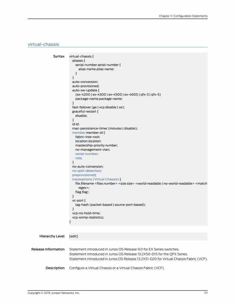
virtual-chassis
Syntax virtual-chassis {aliases {serial-number serial-number {alias-name alias-name;
}}auto-conversion;auto-provisioned;auto-sw-update {(ex-4200 | ex-4300 | ex-4500 | ex-4600 | qfx-3 | qfx-5)package-name package-name;
}fast-failover (ge | vcp disable | xe);graceful-restart {disable;
}id id;mac-persistence-timer (minutes | disable);membermember-id {fabric-tree-root;location location;mastership-priority number;no-management-vlan;serial-number;role;
}no-auto-conversion;no-split-detection;preprovisioned;traceoptions (Virtual Chassis) {file filename <files number> <size size> <world-readable | no-world-readable> <matchregex>;
flag flag ;}vc-port {lag-hash (packet-based | source-port-based);
}vcp-no-hold-time;vcp-snmp-statistics;
}
Hierarchy Level [edit]
Release Information Statement introduced in Junos OS Release 9.0 for EX Series switches.
Statement introduced in Junos OS Release 13.2X50-D15 for the QFX Series.
Statement introduced in JunosOSRelease 13.2X51-D20 for Virtual Chassis Fabric (VCF).
Description Configure a Virtual Chassis or a Virtual Chassis Fabric (VCF).
117Copyright © 2019, Juniper Networks, Inc.
Chapter 11: Configuration Statements
The remaining statements are explained separately. See CLI Explorer.
Default A standalone EX Series switch is a Virtual Chassis by default. It has a default member ID
of 0, a default mastership priority of 128, and a default role as master.
A QFX Series device configured in standalonemode is a Virtual Chassis by default. It has
adefaultmember IDof0, adefaultmastershippriority of 128, andadefault role asmaster.
AstandaloneXRE200ExternalRoutingEngineorEX8200switch isnotpartofanEX8200
Virtual Chassis until a Virtual Chassis configuration is set up.
Required PrivilegeLevel
system—To view this statement in the configuration.
system-control—To add this statement to the configuration.
RelatedDocumentation
• Autoprovisioning a Virtual Chassis Fabric
• Preprovisioning a Virtual Chassis Fabric
• Adding a Device to a Virtual Chassis Fabric
• Configuring a QFX Series Virtual Chassis
• Configuring an EX2300, EX3400, or EX4300 Virtual Chassis
• Configuring EX4600 Switches in a Mixed or Non-Mixed Virtual Chassis
• Configuring an EX9200 Virtual Chassis on page 38
Copyright © 2019, Juniper Networks, Inc.118
Virtual Chassis Feature Guide for EX9200 Switches
CHAPTER 12
Operational Commands: Administrative
• request virtual-chassis member-id delete (MX Series Virtual Chassis)
• request virtual-chassis member-id set
• request virtual-chassis routing-engine master switch
• request virtual-chassis vc-port
119Copyright © 2019, Juniper Networks, Inc.
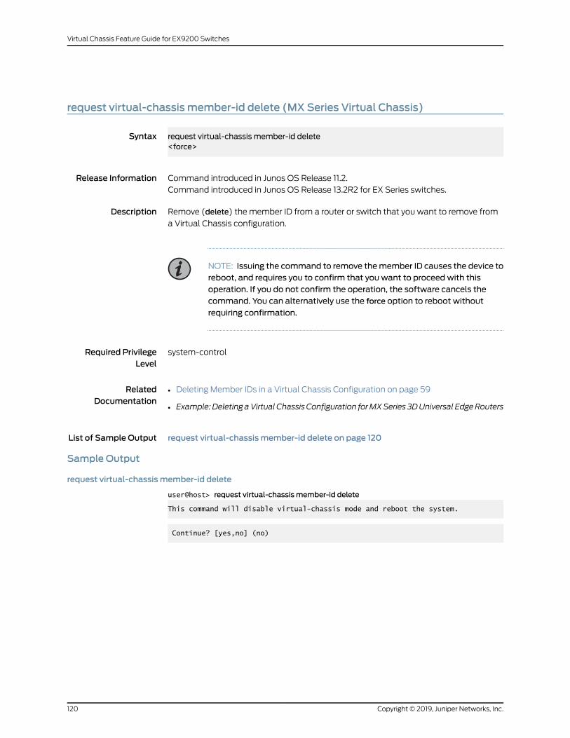
request virtual-chassis member-id delete (MX Series Virtual Chassis)
Syntax request virtual-chassis member-id delete<force>
Release Information Command introduced in Junos OS Release 11.2.
Command introduced in Junos OS Release 13.2R2 for EX Series switches.
Description Remove (delete) the member ID from a router or switch that you want to remove from
a Virtual Chassis configuration.
NOTE: Issuing the command to remove themember ID causes the device toreboot, and requires you to confirm that you want to proceed with thisoperation. If you do not confirm the operation, the software cancels thecommand. You can alternatively use the force option to reboot without
requiring confirmation.
Required PrivilegeLevel
system-control
RelatedDocumentation
Deleting Member IDs in a Virtual Chassis Configuration on page 59•
• Example:DeletingaVirtualChassisConfiguration forMXSeries 3DUniversal EdgeRouters
List of Sample Output request virtual-chassis member-id delete on page 120
Sample Output
request virtual-chassis member-id delete
user@host> request virtual-chassis member-id delete
This command will disable virtual-chassis mode and reboot the system.
Continue? [yes,no] (no)
Copyright © 2019, Juniper Networks, Inc.120
Virtual Chassis Feature Guide for EX9200 Switches
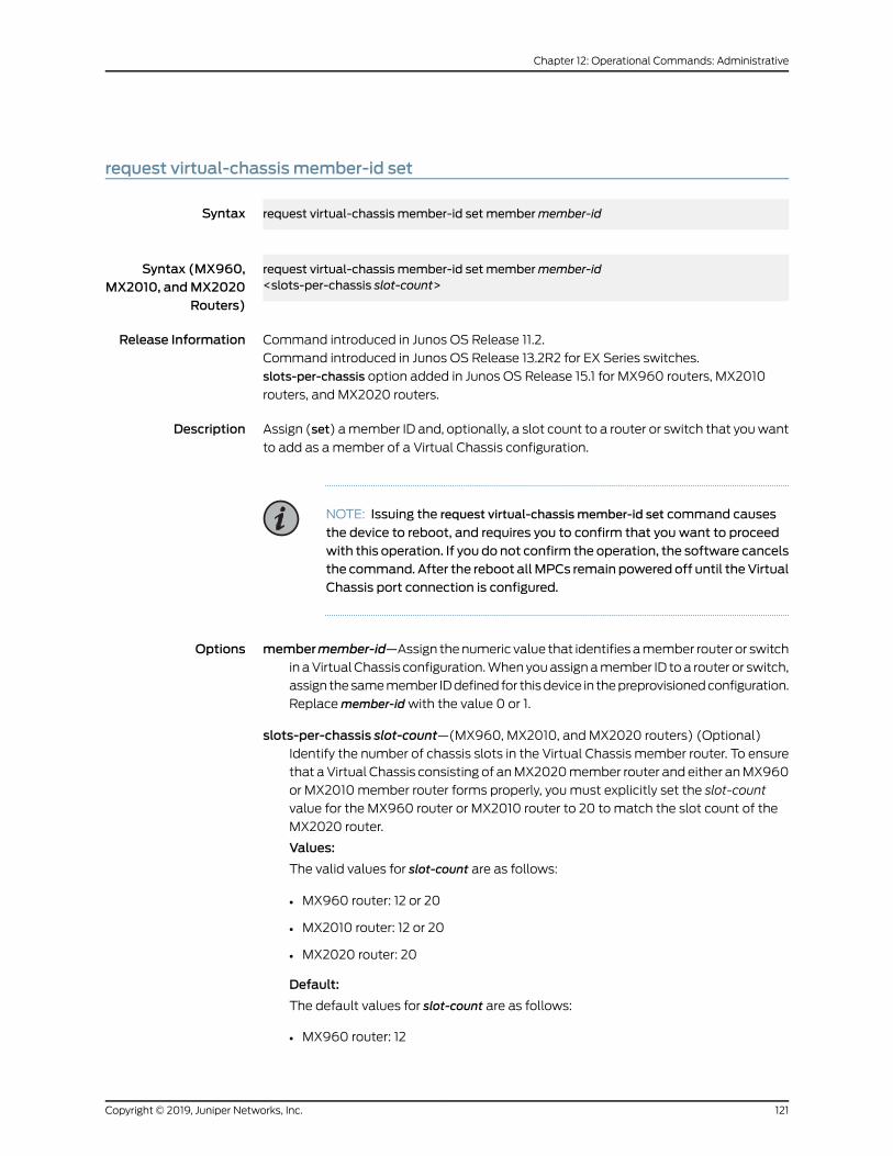
request virtual-chassis member-id set
Syntax request virtual-chassis member-id set membermember-id
Syntax (MX960,MX2010, andMX2020
Routers)
request virtual-chassis member-id set membermember-id<slots-per-chassis slot-count>
Release Information Command introduced in Junos OS Release 11.2.
Command introduced in Junos OS Release 13.2R2 for EX Series switches.
slots-per-chassis option added in Junos OS Release 15.1 for MX960 routers, MX2010
routers, and MX2020 routers.
Description Assign (set) amember ID and, optionally, a slot count to a router or switch that youwant
to add as amember of a Virtual Chassis configuration.
NOTE: Issuing the request virtual-chassis member-id set command causes
the device to reboot, and requires you to confirm that you want to proceedwith this operation. If you do not confirm the operation, the software cancelsthe command. After the reboot allMPCs remain poweredoff until theVirtualChassis port connection is configured.
Options membermember-id—Assign thenumeric value that identifies amember router or switchin aVirtualChassis configuration.Whenyouassignamember ID toa router or switch,
assign thesamemember IDdefined for thisdevice in thepreprovisionedconfiguration.
Replacemember-idwith the value 0 or 1.
slots-per-chassis slot-count—(MX960, MX2010, and MX2020 routers) (Optional)Identify the number of chassis slots in the Virtual Chassis member router. To ensure
that aVirtual Chassis consisting of anMX2020member router and either anMX960
or MX2010member router forms properly, youmust explicitly set the slot-count
value for the MX960 router or MX2010 router to 20 tomatch the slot count of the
MX2020 router.
Values:
The valid values for slot-count are as follows:
• MX960 router: 12 or 20
• MX2010 router: 12 or 20
• MX2020 router: 20
Default:
The default values for slot-count are as follows:
• MX960 router: 12
121Copyright © 2019, Juniper Networks, Inc.
Chapter 12: Operational Commands: Administrative
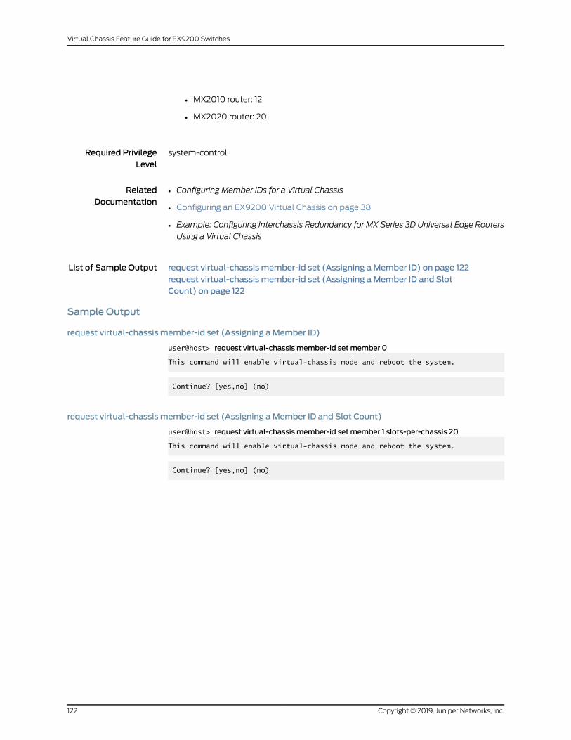
• MX2010 router: 12
• MX2020 router: 20
Required PrivilegeLevel
system-control
RelatedDocumentation
Configuring Member IDs for a Virtual Chassis•
• Configuring an EX9200 Virtual Chassis on page 38
• Example: Configuring Interchassis Redundancy for MX Series 3D Universal Edge Routers
Using a Virtual Chassis
List of Sample Output request virtual-chassis member-id set (Assigning aMember ID) on page 122request virtual-chassis member-id set (Assigning aMember ID and SlotCount) on page 122
Sample Output
request virtual-chassis member-id set (Assigning aMember ID)
user@host> request virtual-chassis member-id setmember 0
This command will enable virtual-chassis mode and reboot the system.
Continue? [yes,no] (no)
request virtual-chassis member-id set (Assigning aMember ID and Slot Count)
user@host> request virtual-chassis member-id setmember 1 slots-per-chassis 20
This command will enable virtual-chassis mode and reboot the system.
Continue? [yes,no] (no)
Copyright © 2019, Juniper Networks, Inc.122
Virtual Chassis Feature Guide for EX9200 Switches
request virtual-chassis routing-enginemaster switch
Syntax request virtual-chassis routing-enginemaster switch<check>
Release Information Command introduced in Junos OS Release 11.2.
Option check introduced in Junos OS Release 12.2.
Command introduced in Junos OS Release 13.2R2 for EX Series switches.
Description Change themastership in an MX Series Virtual Chassis or EX9200 Virtual Chassis by
switching the global roles of the master router or switch and backup router or switch in
theVirtualChassis configuration. The requestvirtual-chassis routing-enginemaster switch
commandmust be issued from themaster router or switch (VC-Mm).
(MX Series routers only) The local roles (master and standby, orm and s) of the Routing
Engines in the Virtual Chassis master router change after a global switchover, but the
local roles of the Routing Engines in the Virtual Chassis backup router do not change. For
example, the master Routing Engine in the Virtual Chassis master router (VC-Mm)
becomes the standby Routing Engine in the Virtual Chassis backup router (VC-Bs) after
the global switchover. By contrast, the master Routing Engine in the Virtual Chassis
backup router (VC-Bm) remains themaster Routing Engine in the Virtual Chassismaster
router (VC-Mm) after the global switchover.
NOTE: Before you issue the request virtual-chassis routing-enginemaster
switch command from themaster router or switch in the Virtual Chassis,
makesure that the systemconfiguration is synchronizedbetween themasterand backup router or switch. If the configuration is not synchronized, or if youattempt to issue the request virtual-chassis routing-enginemaster switch
commandfromthebackup routeror switch insteadof fromthemaster routeror switch, the device displays an error message and rejects the command.
If you issue the requestvirtual-chassis routing-enginemaster switchcommand
when the Virtual Chassis is in a transition state (for example, the backuprouter or switch is disconnecting from the Virtual Chassis), the device doesnot process the command.
Options check—(Optional)Performacheck fromthemaster routeror switch todeterminewhether
themember routers or switchesare ready forGRES fromadatabase synchronization
perspective, without initiating the GRES operation itself.
Required PrivilegeLevel
system-control
123Copyright © 2019, Juniper Networks, Inc.
Chapter 12: Operational Commands: Administrative
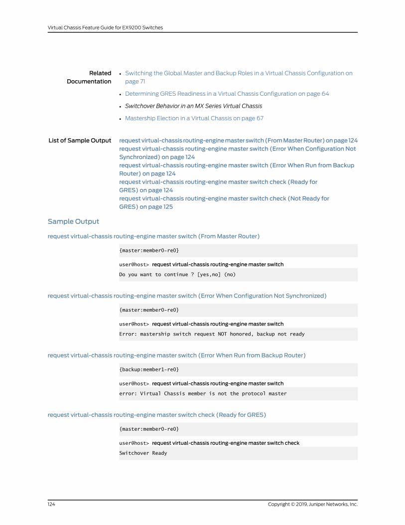
RelatedDocumentation
Switching the Global Master and Backup Roles in a Virtual Chassis Configuration on
page 71
•
• Determining GRES Readiness in a Virtual Chassis Configuration on page 64
• Switchover Behavior in an MX Series Virtual Chassis
• Mastership Election in a Virtual Chassis on page 67
List of Sample Output requestvirtual-chassis routing-enginemasterswitch(FromMasterRouter)onpage124request virtual-chassis routing-enginemaster switch (ErrorWhen Configuration NotSynchronized) on page 124request virtual-chassis routing-enginemaster switch (ErrorWhen Run fromBackupRouter) on page 124request virtual-chassis routing-enginemaster switch check (Ready forGRES) on page 124request virtual-chassis routing-enginemaster switch check (Not Ready forGRES) on page 125
Sample Output
request virtual-chassis routing-enginemaster switch (FromMaster Router)
{master:member0-re0}
user@host> request virtual-chassis routing-enginemaster switch
Do you want to continue ? [yes,no] (no)
request virtual-chassis routing-enginemaster switch (ErrorWhen Configuration Not Synchronized)
{master:member0-re0}
user@host> request virtual-chassis routing-enginemaster switch
Error: mastership switch request NOT honored, backup not ready
request virtual-chassis routing-enginemaster switch (ErrorWhen Run fromBackup Router)
{backup:member1-re0}
user@host> request virtual-chassis routing-enginemaster switch
error: Virtual Chassis member is not the protocol master
request virtual-chassis routing-enginemaster switch check (Ready for GRES)
{master:member0-re0}
user@host> request virtual-chassis routing-enginemaster switch check
Switchover Ready
Copyright © 2019, Juniper Networks, Inc.124
Virtual Chassis Feature Guide for EX9200 Switches
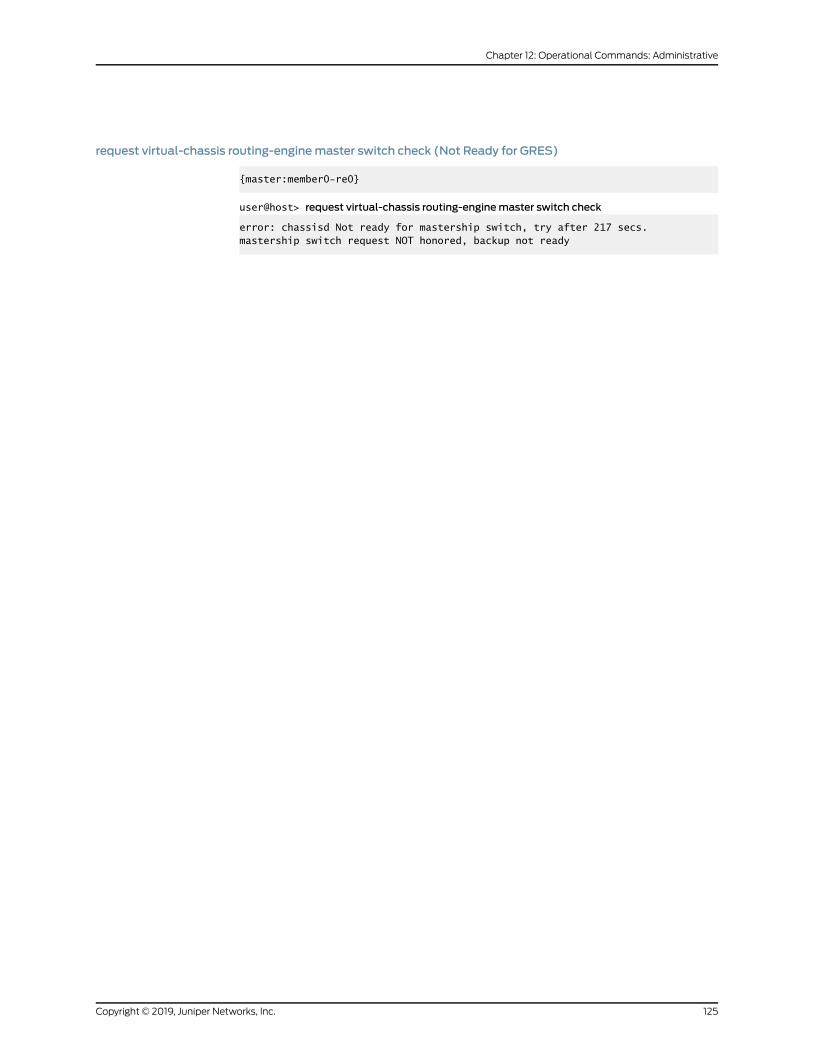
request virtual-chassis routing-enginemaster switch check (Not Ready for GRES)
{master:member0-re0}
user@host> request virtual-chassis routing-enginemaster switch check
error: chassisd Not ready for mastership switch, try after 217 secs.mastership switch request NOT honored, backup not ready
125Copyright © 2019, Juniper Networks, Inc.
Chapter 12: Operational Commands: Administrative
request virtual-chassis vc-port
Syntax request virtual-chassis vc-port [set | delete]<fpc-slot fpc-slot>pic-slot pic-slotport port-number<membermember-id>
Release Information Command introduced in Junos OS Release 9.0 for EX Series switches.
Option fpc-slot introduced in Junos OS Release 10.4 for EX Series switches.
Command introduced in Junos OS Release 13.2X50-D15 for the QFX Series.
Command introduced in Junos OSRelease 13.2X51-D20 for Virtual Chassis Fabric (VCF).
Description Enable or disable an optical port as a Virtual Chassis port (VCP).
If youomitmembermember-id, this commanddefaults to enablingor disabling theuplink
VCP or SFP network port configured as a VCP on the switch where the command is
issued.
Youmight experiencea temporary traffic disruption immediately after creatingordeleting
a user-configured VCP in an EX8200 Virtual Chassis.
NOTE: Some EX Series switches have ports that are configured as VCPs bydefault. You do not need to explicitly configure those ports as VCPs to usethem to interconnect the switch into a Virtual Chassis. See “UnderstandingVirtual Chassis Components” on page 16 for details.
Options set—Set a network port as a VCP to convert a network port into a VCP.
delete—Delete the VCP setting on a port to convert a VCP into a network port.
pic-slot pic-slot—Number of the PIC slot for the port on the switch.
port port-number—Number of the port that is to be enabled or disabled as a VCP.
membermember-id—(Optional) Enable or disable the specified VCP on the specifiedmember of the Virtual Chassis or VCF.
Required PrivilegeLevel
system-control
RelatedDocumentation
request virtual-chassis vc-port (Dedicated VCP)•
• show virtual-chassis vc-port on page 166
• show virtual-chassis vc-port statistics
Copyright © 2019, Juniper Networks, Inc.126
Virtual Chassis Feature Guide for EX9200 Switches
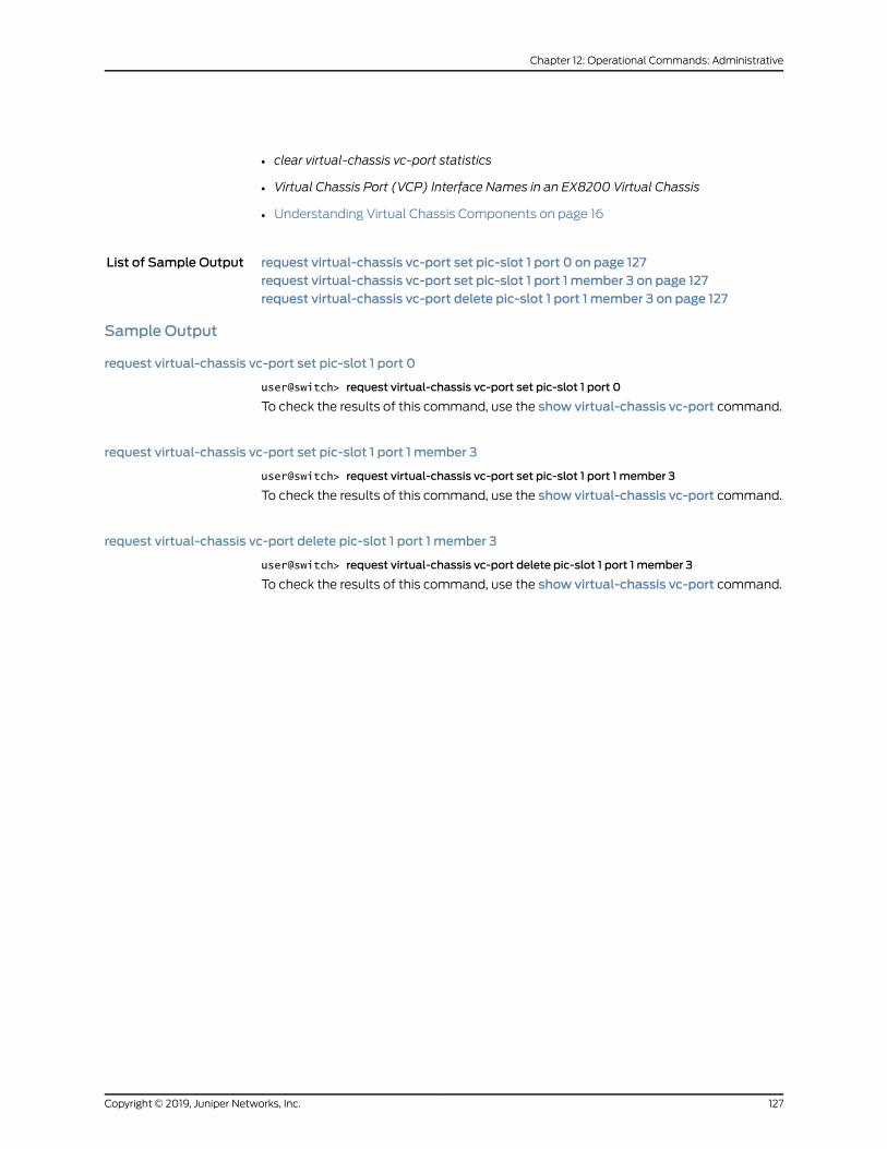
• clear virtual-chassis vc-port statistics
• Virtual Chassis Port (VCP) Interface Names in an EX8200 Virtual Chassis
• Understanding Virtual Chassis Components on page 16
List of Sample Output request virtual-chassis vc-port set pic-slot 1 port 0 on page 127request virtual-chassis vc-port set pic-slot 1 port 1 member 3 on page 127request virtual-chassis vc-port delete pic-slot 1 port 1 member 3 on page 127
Sample Output
request virtual-chassis vc-port set pic-slot 1 port 0
user@switch> request virtual-chassis vc-port set pic-slot 1 port 0
To check the results of this command, use the show virtual-chassis vc-port command.
request virtual-chassis vc-port set pic-slot 1 port 1 member 3
user@switch> request virtual-chassis vc-port set pic-slot 1 port 1 member 3
To check the results of this command, use the show virtual-chassis vc-port command.
request virtual-chassis vc-port delete pic-slot 1 port 1 member 3
user@switch> request virtual-chassis vc-port delete pic-slot 1 port 1 member 3
To check the results of this command, use the show virtual-chassis vc-port command.
127Copyright © 2019, Juniper Networks, Inc.
Chapter 12: Operational Commands: Administrative

Copyright © 2019, Juniper Networks, Inc.128
Virtual Chassis Feature Guide for EX9200 Switches
CHAPTER 13
Operational Commands: Monitoring
• show virtual-chassis active-topology
• show virtual-chassis device-topology
• show virtual-chassis protocol adjacency
• show virtual-chassis protocol database
• show virtual-chassis protocol interface
• show virtual-chassis protocol route
• show virtual-chassis protocol statistics
• show virtual-chassis
• show virtual-chassis vc-port
129Copyright © 2019, Juniper Networks, Inc.
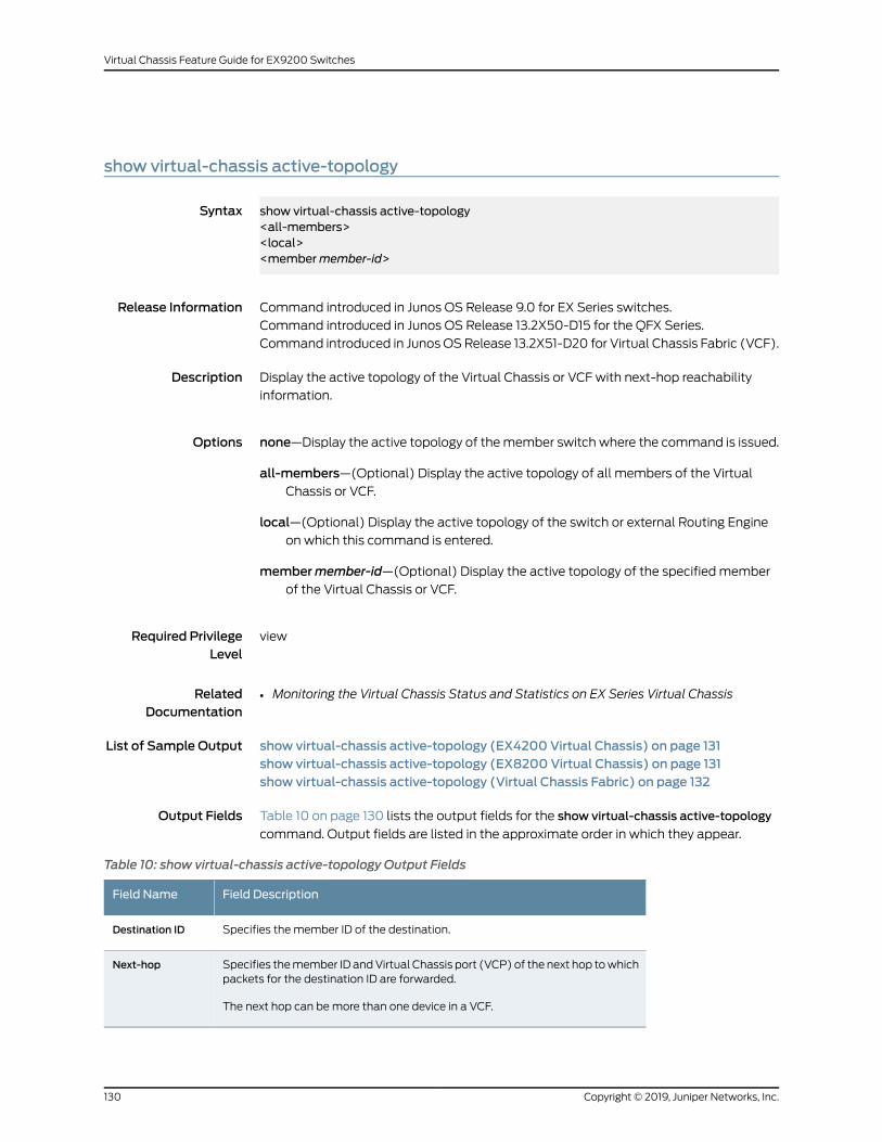
show virtual-chassis active-topology
Syntax show virtual-chassis active-topology<all-members><local><membermember-id>
Release Information Command introduced in Junos OS Release 9.0 for EX Series switches.
Command introduced in Junos OS Release 13.2X50-D15 for the QFX Series.
Command introduced in Junos OSRelease 13.2X51-D20 for Virtual Chassis Fabric (VCF).
Description Display the active topology of the Virtual Chassis or VCF with next-hop reachability
information.
Options none—Display the active topology of themember switch where the command is issued.
all-members—(Optional) Display the active topology of all members of the VirtualChassis or VCF.
local—(Optional) Display the active topology of the switch or external Routing Engineon which this command is entered.
membermember-id—(Optional) Display the active topology of the specified memberof the Virtual Chassis or VCF.
Required PrivilegeLevel
view
RelatedDocumentation
Monitoring the Virtual Chassis Status and Statistics on EX Series Virtual Chassis•
List of Sample Output show virtual-chassis active-topology (EX4200 Virtual Chassis) on page 131show virtual-chassis active-topology (EX8200 Virtual Chassis) on page 131show virtual-chassis active-topology (Virtual Chassis Fabric) on page 132
Output Fields Table 10 on page 130 lists the output fields for the show virtual-chassis active-topology
command. Output fields are listed in the approximate order in which they appear.
Table 10: show virtual-chassis active-topology Output Fields
Field DescriptionField Name
Specifies the member ID of the destination.Destination ID
Specifies themember ID andVirtual Chassis port (VCP) of the next hop towhichpackets for the destination ID are forwarded.
The next hop can bemore than one device in a VCF.
Next-hop
Copyright © 2019, Juniper Networks, Inc.130
Virtual Chassis Feature Guide for EX9200 Switches
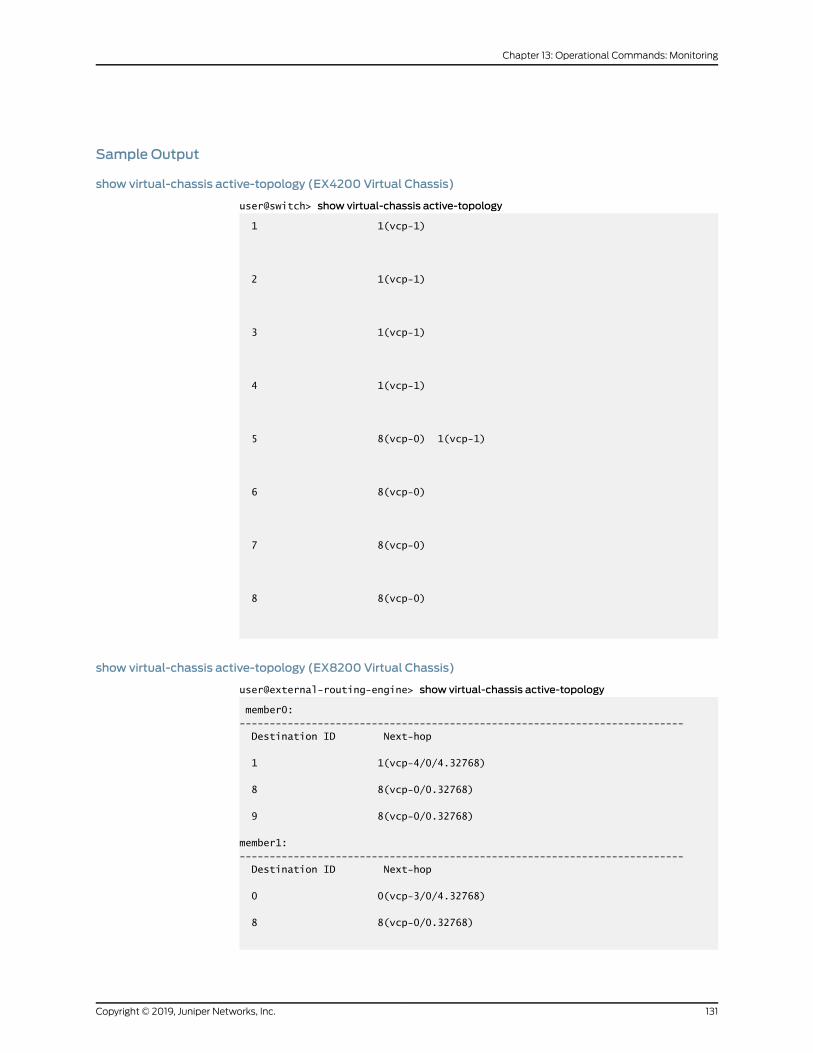
Sample Output
show virtual-chassis active-topology (EX4200 Virtual Chassis)
user@switch> show virtual-chassis active-topology
1 1(vcp-1)
2 1(vcp-1)
3 1(vcp-1)
4 1(vcp-1)
5 8(vcp-0) 1(vcp-1)
6 8(vcp-0)
7 8(vcp-0)
8 8(vcp-0)
show virtual-chassis active-topology (EX8200 Virtual Chassis)
user@external-routing-engine> show virtual-chassis active-topology
member0:-------------------------------------------------------------------------- Destination ID Next-hop
1 1(vcp-4/0/4.32768)
8 8(vcp-0/0.32768)
9 8(vcp-0/0.32768)
member1:-------------------------------------------------------------------------- Destination ID Next-hop
0 0(vcp-3/0/4.32768)
8 8(vcp-0/0.32768)
131Copyright © 2019, Juniper Networks, Inc.
Chapter 13: Operational Commands: Monitoring
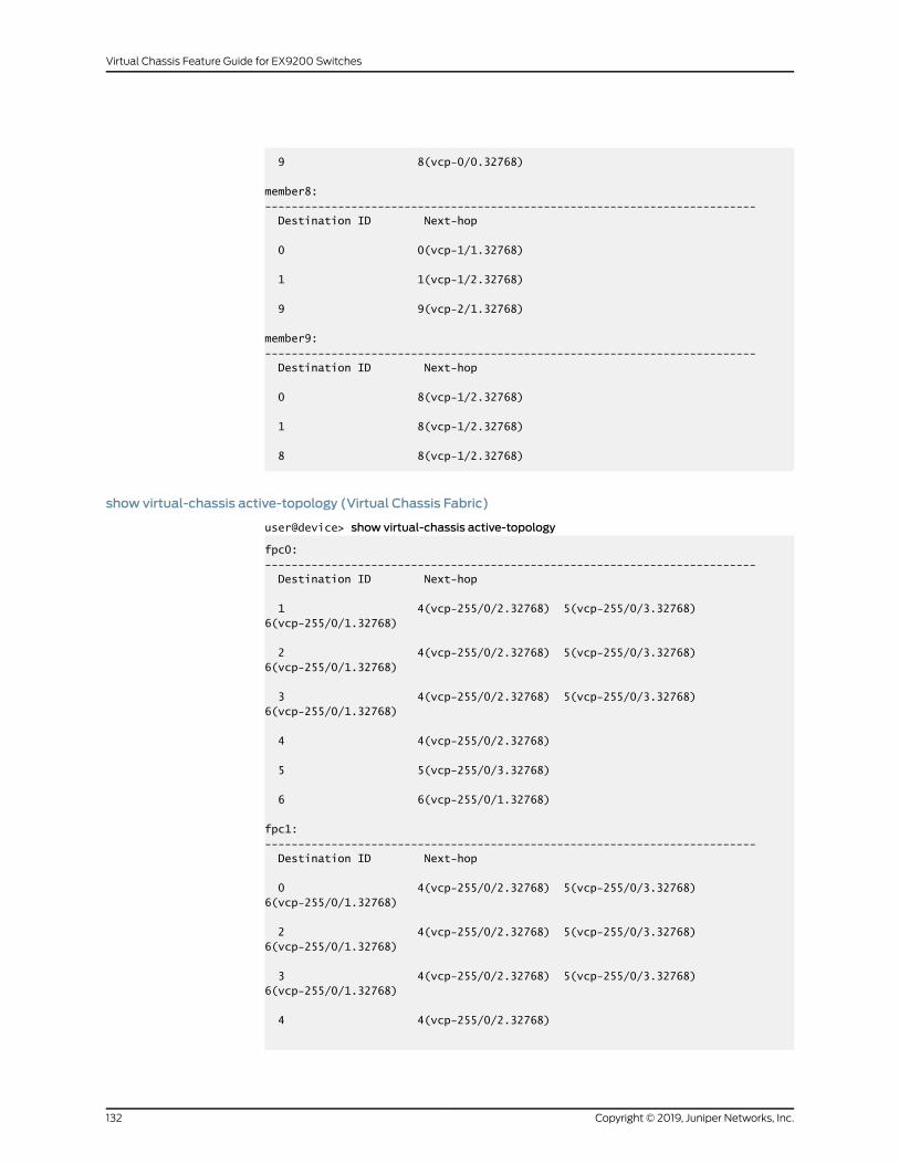
9 8(vcp-0/0.32768)
member8:-------------------------------------------------------------------------- Destination ID Next-hop
0 0(vcp-1/1.32768)
1 1(vcp-1/2.32768)
9 9(vcp-2/1.32768)
member9:-------------------------------------------------------------------------- Destination ID Next-hop
0 8(vcp-1/2.32768)
1 8(vcp-1/2.32768)
8 8(vcp-1/2.32768)
show virtual-chassis active-topology (Virtual Chassis Fabric)
user@device> show virtual-chassis active-topology
fpc0:-------------------------------------------------------------------------- Destination ID Next-hop
1 4(vcp-255/0/2.32768) 5(vcp-255/0/3.32768) 6(vcp-255/0/1.32768)
2 4(vcp-255/0/2.32768) 5(vcp-255/0/3.32768) 6(vcp-255/0/1.32768)
3 4(vcp-255/0/2.32768) 5(vcp-255/0/3.32768) 6(vcp-255/0/1.32768)
4 4(vcp-255/0/2.32768)
5 5(vcp-255/0/3.32768)
6 6(vcp-255/0/1.32768)
fpc1:-------------------------------------------------------------------------- Destination ID Next-hop
0 4(vcp-255/0/2.32768) 5(vcp-255/0/3.32768) 6(vcp-255/0/1.32768)
2 4(vcp-255/0/2.32768) 5(vcp-255/0/3.32768) 6(vcp-255/0/1.32768)
3 4(vcp-255/0/2.32768) 5(vcp-255/0/3.32768) 6(vcp-255/0/1.32768)
4 4(vcp-255/0/2.32768)
Copyright © 2019, Juniper Networks, Inc.132
Virtual Chassis Feature Guide for EX9200 Switches
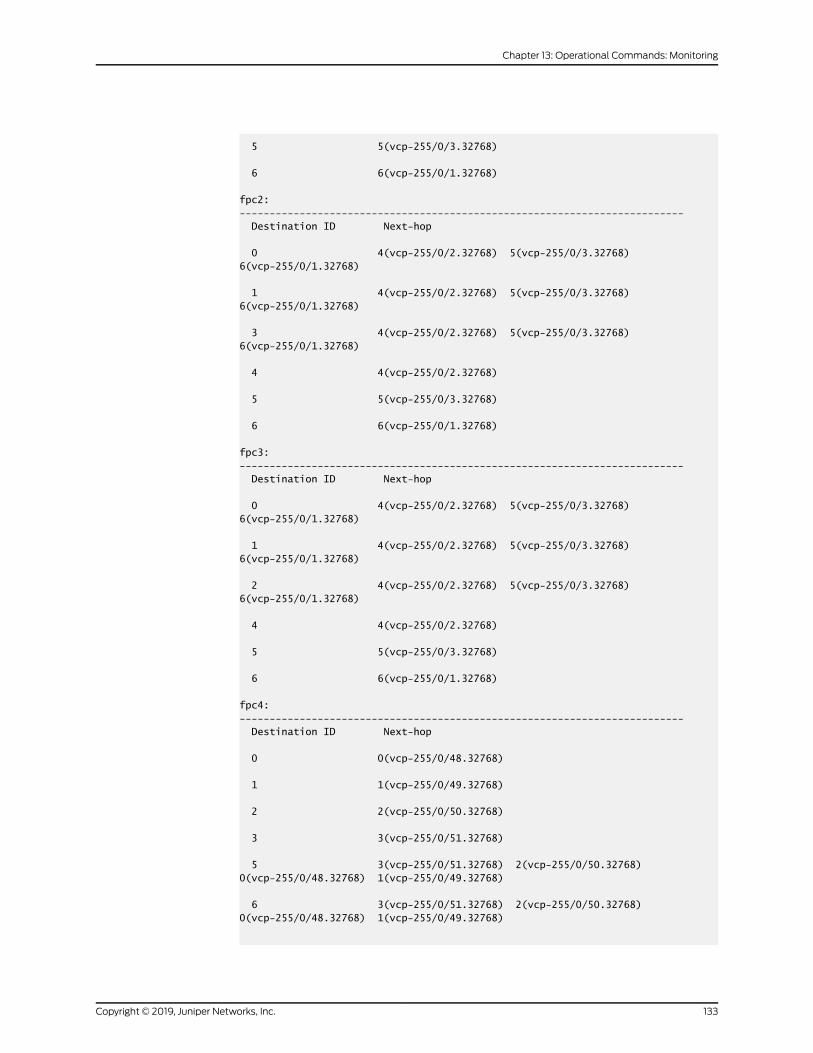
5 5(vcp-255/0/3.32768)
6 6(vcp-255/0/1.32768)
fpc2:-------------------------------------------------------------------------- Destination ID Next-hop
0 4(vcp-255/0/2.32768) 5(vcp-255/0/3.32768) 6(vcp-255/0/1.32768)
1 4(vcp-255/0/2.32768) 5(vcp-255/0/3.32768) 6(vcp-255/0/1.32768)
3 4(vcp-255/0/2.32768) 5(vcp-255/0/3.32768) 6(vcp-255/0/1.32768)
4 4(vcp-255/0/2.32768)
5 5(vcp-255/0/3.32768)
6 6(vcp-255/0/1.32768)
fpc3:-------------------------------------------------------------------------- Destination ID Next-hop
0 4(vcp-255/0/2.32768) 5(vcp-255/0/3.32768) 6(vcp-255/0/1.32768)
1 4(vcp-255/0/2.32768) 5(vcp-255/0/3.32768) 6(vcp-255/0/1.32768)
2 4(vcp-255/0/2.32768) 5(vcp-255/0/3.32768) 6(vcp-255/0/1.32768)
4 4(vcp-255/0/2.32768)
5 5(vcp-255/0/3.32768)
6 6(vcp-255/0/1.32768)
fpc4:-------------------------------------------------------------------------- Destination ID Next-hop
0 0(vcp-255/0/48.32768)
1 1(vcp-255/0/49.32768)
2 2(vcp-255/0/50.32768)
3 3(vcp-255/0/51.32768)
5 3(vcp-255/0/51.32768) 2(vcp-255/0/50.32768) 0(vcp-255/0/48.32768) 1(vcp-255/0/49.32768)
6 3(vcp-255/0/51.32768) 2(vcp-255/0/50.32768) 0(vcp-255/0/48.32768) 1(vcp-255/0/49.32768)
133Copyright © 2019, Juniper Networks, Inc.
Chapter 13: Operational Commands: Monitoring
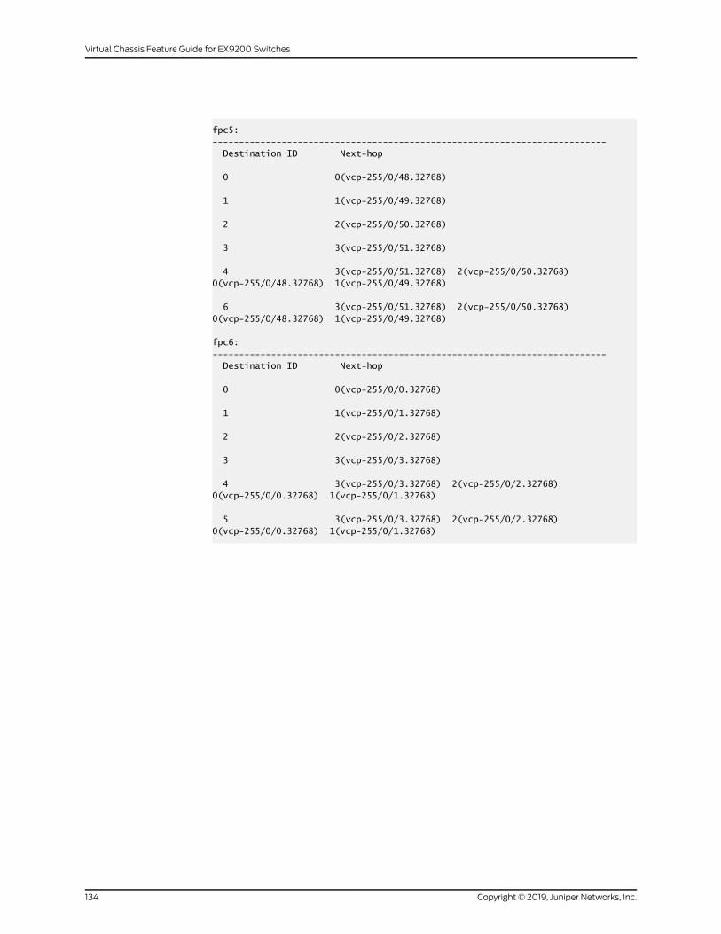
fpc5:-------------------------------------------------------------------------- Destination ID Next-hop
0 0(vcp-255/0/48.32768)
1 1(vcp-255/0/49.32768)
2 2(vcp-255/0/50.32768)
3 3(vcp-255/0/51.32768)
4 3(vcp-255/0/51.32768) 2(vcp-255/0/50.32768) 0(vcp-255/0/48.32768) 1(vcp-255/0/49.32768)
6 3(vcp-255/0/51.32768) 2(vcp-255/0/50.32768) 0(vcp-255/0/48.32768) 1(vcp-255/0/49.32768)
fpc6:-------------------------------------------------------------------------- Destination ID Next-hop
0 0(vcp-255/0/0.32768)
1 1(vcp-255/0/1.32768)
2 2(vcp-255/0/2.32768)
3 3(vcp-255/0/3.32768)
4 3(vcp-255/0/3.32768) 2(vcp-255/0/2.32768) 0(vcp-255/0/0.32768) 1(vcp-255/0/1.32768)
5 3(vcp-255/0/3.32768) 2(vcp-255/0/2.32768) 0(vcp-255/0/0.32768) 1(vcp-255/0/1.32768)
Copyright © 2019, Juniper Networks, Inc.134
Virtual Chassis Feature Guide for EX9200 Switches
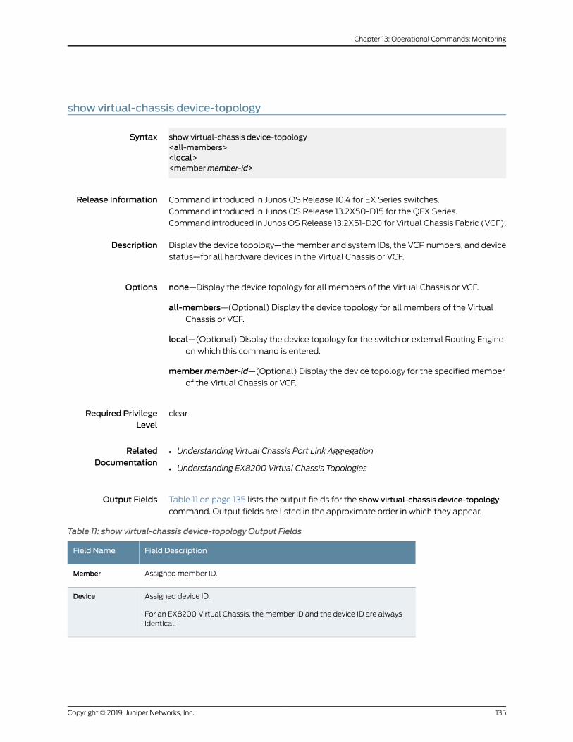
show virtual-chassis device-topology
Syntax show virtual-chassis device-topology<all-members><local><membermember-id>
Release Information Command introduced in Junos OS Release 10.4 for EX Series switches.
Command introduced in Junos OS Release 13.2X50-D15 for the QFX Series.
Command introduced in Junos OSRelease 13.2X51-D20 for Virtual Chassis Fabric (VCF).
Description Display the device topology—themember and system IDs, the VCP numbers, and device
status—for all hardware devices in the Virtual Chassis or VCF.
Options none—Display the device topology for all members of the Virtual Chassis or VCF.
all-members—(Optional) Display the device topology for all members of the VirtualChassis or VCF.
local—(Optional) Display the device topology for the switch or external Routing Engineon which this command is entered.
membermember-id—(Optional) Display the device topology for the specified memberof the Virtual Chassis or VCF.
Required PrivilegeLevel
clear
RelatedDocumentation
Understanding Virtual Chassis Port Link Aggregation•
• Understanding EX8200 Virtual Chassis Topologies
Output Fields Table 11 on page 135 lists the output fields for the show virtual-chassis device-topology
command. Output fields are listed in the approximate order in which they appear.
Table 11: show virtual-chassis device-topology Output Fields
Field DescriptionField Name
Assignedmember ID.Member
Assigned device ID.
For an EX8200 Virtual Chassis, the member ID and the device ID are alwaysidentical.
Device
135Copyright © 2019, Juniper Networks, Inc.
Chapter 13: Operational Commands: Monitoring
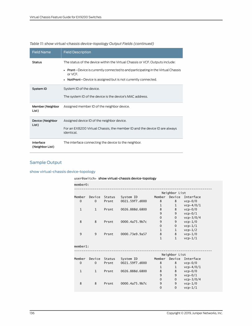
Table 11: show virtual-chassis device-topology Output Fields (continued)
Field DescriptionField Name
The status of the device within the Virtual Chassis or VCF. Outputs include:
• Prsnt—Device is currently connected toandparticipating in theVirtualChassisor VCF.
• NotPrsnt—Device is assigned but is not currently connected.
Status
System ID of the device.
The system ID of the device is the device’s MAC address.
System ID
Assignedmember ID of the neighbor device.Member(NeighborList)
Assigned device ID of the neighbor device.
For an EX8200 Virtual Chassis, the member ID and the device ID are alwaysidentical.
Device (NeighborList)
The interface connecting the device to the neighbor.Interface(Neighbor List)
Sample Output
show virtual-chassis device-topology
user@switch> show virtual-chassis device-topology
member0:-------------------------------------------------------------------------- Neighbor ListMember Device Status System ID Member Device Interface 0 0 Prsnt 0021.59f7.d000 8 8 vcp-0/0 1 1 vcp-4/0/1 1 1 Prsnt 0026.888d.6800 8 8 vcp-0/0 9 9 vcp-0/1 0 0 vcp-3/0/4 8 8 Prsnt 0000.4a75.9b7c 9 9 vcp-1/0 0 0 vcp-1/1 1 1 vcp-1/2 9 9 Prsnt 0000.73e9.9a57 8 8 vcp-1/0 1 1 vcp-1/1
member1:-------------------------------------------------------------------------- Neighbor ListMember Device Status System ID Member Device Interface 0 0 Prsnt 0021.59f7.d000 8 8 vcp-0/0 1 1 vcp-4/0/1 1 1 Prsnt 0026.888d.6800 8 8 vcp-0/0 9 9 vcp-0/1 0 0 vcp-3/0/4 8 8 Prsnt 0000.4a75.9b7c 9 9 vcp-1/0 0 0 vcp-1/1
Copyright © 2019, Juniper Networks, Inc.136
Virtual Chassis Feature Guide for EX9200 Switches
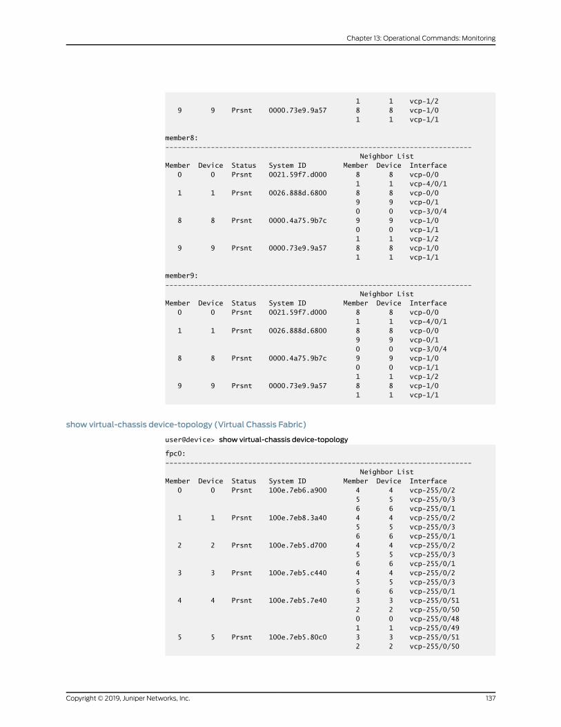
1 1 vcp-1/2 9 9 Prsnt 0000.73e9.9a57 8 8 vcp-1/0 1 1 vcp-1/1
member8:-------------------------------------------------------------------------- Neighbor ListMember Device Status System ID Member Device Interface 0 0 Prsnt 0021.59f7.d000 8 8 vcp-0/0 1 1 vcp-4/0/1 1 1 Prsnt 0026.888d.6800 8 8 vcp-0/0 9 9 vcp-0/1 0 0 vcp-3/0/4 8 8 Prsnt 0000.4a75.9b7c 9 9 vcp-1/0 0 0 vcp-1/1 1 1 vcp-1/2 9 9 Prsnt 0000.73e9.9a57 8 8 vcp-1/0 1 1 vcp-1/1
member9:-------------------------------------------------------------------------- Neighbor ListMember Device Status System ID Member Device Interface 0 0 Prsnt 0021.59f7.d000 8 8 vcp-0/0 1 1 vcp-4/0/1 1 1 Prsnt 0026.888d.6800 8 8 vcp-0/0 9 9 vcp-0/1 0 0 vcp-3/0/4 8 8 Prsnt 0000.4a75.9b7c 9 9 vcp-1/0 0 0 vcp-1/1 1 1 vcp-1/2 9 9 Prsnt 0000.73e9.9a57 8 8 vcp-1/0 1 1 vcp-1/1
show virtual-chassis device-topology (Virtual Chassis Fabric)
user@device> show virtual-chassis device-topology
fpc0:-------------------------------------------------------------------------- Neighbor ListMember Device Status System ID Member Device Interface 0 0 Prsnt 100e.7eb6.a900 4 4 vcp-255/0/2 5 5 vcp-255/0/3 6 6 vcp-255/0/1 1 1 Prsnt 100e.7eb8.3a40 4 4 vcp-255/0/2 5 5 vcp-255/0/3 6 6 vcp-255/0/1 2 2 Prsnt 100e.7eb5.d700 4 4 vcp-255/0/2 5 5 vcp-255/0/3 6 6 vcp-255/0/1 3 3 Prsnt 100e.7eb5.c440 4 4 vcp-255/0/2 5 5 vcp-255/0/3 6 6 vcp-255/0/1 4 4 Prsnt 100e.7eb5.7e40 3 3 vcp-255/0/51 2 2 vcp-255/0/50 0 0 vcp-255/0/48 1 1 vcp-255/0/49 5 5 Prsnt 100e.7eb5.80c0 3 3 vcp-255/0/51 2 2 vcp-255/0/50
137Copyright © 2019, Juniper Networks, Inc.
Chapter 13: Operational Commands: Monitoring
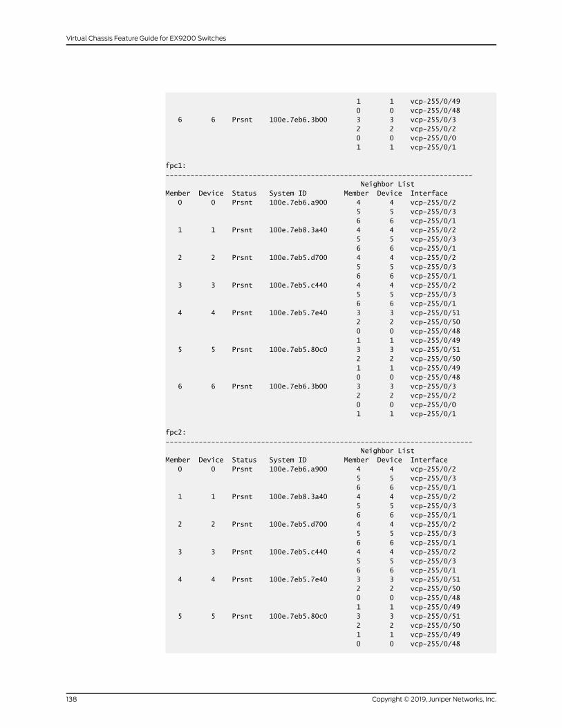
1 1 vcp-255/0/49 0 0 vcp-255/0/48 6 6 Prsnt 100e.7eb6.3b00 3 3 vcp-255/0/3 2 2 vcp-255/0/2 0 0 vcp-255/0/0 1 1 vcp-255/0/1
fpc1:-------------------------------------------------------------------------- Neighbor ListMember Device Status System ID Member Device Interface 0 0 Prsnt 100e.7eb6.a900 4 4 vcp-255/0/2 5 5 vcp-255/0/3 6 6 vcp-255/0/1 1 1 Prsnt 100e.7eb8.3a40 4 4 vcp-255/0/2 5 5 vcp-255/0/3 6 6 vcp-255/0/1 2 2 Prsnt 100e.7eb5.d700 4 4 vcp-255/0/2 5 5 vcp-255/0/3 6 6 vcp-255/0/1 3 3 Prsnt 100e.7eb5.c440 4 4 vcp-255/0/2 5 5 vcp-255/0/3 6 6 vcp-255/0/1 4 4 Prsnt 100e.7eb5.7e40 3 3 vcp-255/0/51 2 2 vcp-255/0/50 0 0 vcp-255/0/48 1 1 vcp-255/0/49 5 5 Prsnt 100e.7eb5.80c0 3 3 vcp-255/0/51 2 2 vcp-255/0/50 1 1 vcp-255/0/49 0 0 vcp-255/0/48 6 6 Prsnt 100e.7eb6.3b00 3 3 vcp-255/0/3 2 2 vcp-255/0/2 0 0 vcp-255/0/0 1 1 vcp-255/0/1
fpc2:-------------------------------------------------------------------------- Neighbor ListMember Device Status System ID Member Device Interface 0 0 Prsnt 100e.7eb6.a900 4 4 vcp-255/0/2 5 5 vcp-255/0/3 6 6 vcp-255/0/1 1 1 Prsnt 100e.7eb8.3a40 4 4 vcp-255/0/2 5 5 vcp-255/0/3 6 6 vcp-255/0/1 2 2 Prsnt 100e.7eb5.d700 4 4 vcp-255/0/2 5 5 vcp-255/0/3 6 6 vcp-255/0/1 3 3 Prsnt 100e.7eb5.c440 4 4 vcp-255/0/2 5 5 vcp-255/0/3 6 6 vcp-255/0/1 4 4 Prsnt 100e.7eb5.7e40 3 3 vcp-255/0/51 2 2 vcp-255/0/50 0 0 vcp-255/0/48 1 1 vcp-255/0/49 5 5 Prsnt 100e.7eb5.80c0 3 3 vcp-255/0/51 2 2 vcp-255/0/50 1 1 vcp-255/0/49 0 0 vcp-255/0/48
Copyright © 2019, Juniper Networks, Inc.138
Virtual Chassis Feature Guide for EX9200 Switches
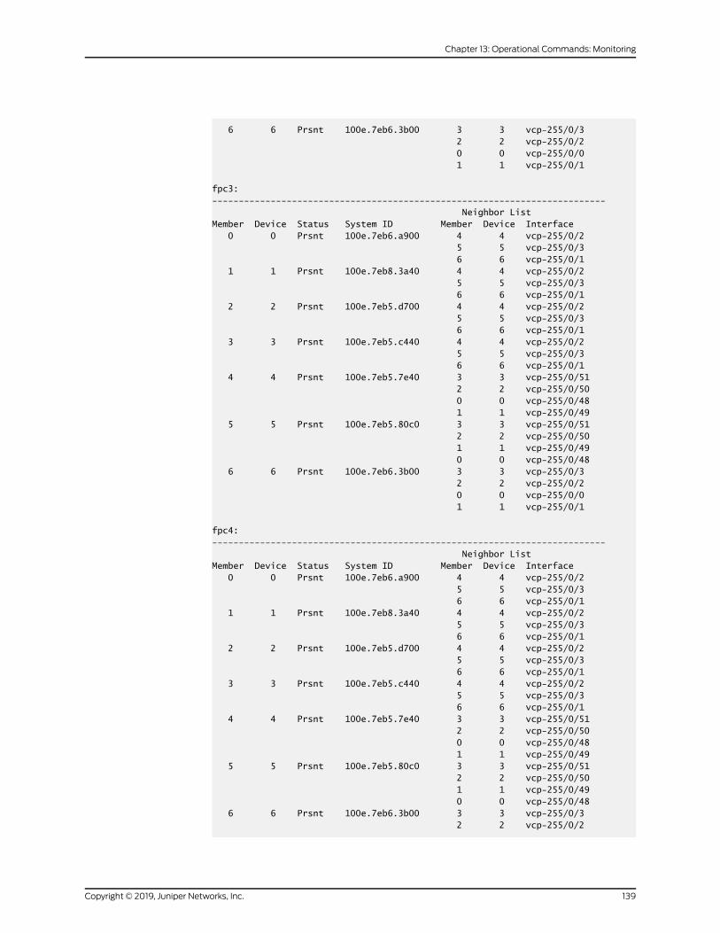
6 6 Prsnt 100e.7eb6.3b00 3 3 vcp-255/0/3 2 2 vcp-255/0/2 0 0 vcp-255/0/0 1 1 vcp-255/0/1
fpc3:-------------------------------------------------------------------------- Neighbor ListMember Device Status System ID Member Device Interface 0 0 Prsnt 100e.7eb6.a900 4 4 vcp-255/0/2 5 5 vcp-255/0/3 6 6 vcp-255/0/1 1 1 Prsnt 100e.7eb8.3a40 4 4 vcp-255/0/2 5 5 vcp-255/0/3 6 6 vcp-255/0/1 2 2 Prsnt 100e.7eb5.d700 4 4 vcp-255/0/2 5 5 vcp-255/0/3 6 6 vcp-255/0/1 3 3 Prsnt 100e.7eb5.c440 4 4 vcp-255/0/2 5 5 vcp-255/0/3 6 6 vcp-255/0/1 4 4 Prsnt 100e.7eb5.7e40 3 3 vcp-255/0/51 2 2 vcp-255/0/50 0 0 vcp-255/0/48 1 1 vcp-255/0/49 5 5 Prsnt 100e.7eb5.80c0 3 3 vcp-255/0/51 2 2 vcp-255/0/50 1 1 vcp-255/0/49 0 0 vcp-255/0/48 6 6 Prsnt 100e.7eb6.3b00 3 3 vcp-255/0/3 2 2 vcp-255/0/2 0 0 vcp-255/0/0 1 1 vcp-255/0/1
fpc4:-------------------------------------------------------------------------- Neighbor ListMember Device Status System ID Member Device Interface 0 0 Prsnt 100e.7eb6.a900 4 4 vcp-255/0/2 5 5 vcp-255/0/3 6 6 vcp-255/0/1 1 1 Prsnt 100e.7eb8.3a40 4 4 vcp-255/0/2 5 5 vcp-255/0/3 6 6 vcp-255/0/1 2 2 Prsnt 100e.7eb5.d700 4 4 vcp-255/0/2 5 5 vcp-255/0/3 6 6 vcp-255/0/1 3 3 Prsnt 100e.7eb5.c440 4 4 vcp-255/0/2 5 5 vcp-255/0/3 6 6 vcp-255/0/1 4 4 Prsnt 100e.7eb5.7e40 3 3 vcp-255/0/51 2 2 vcp-255/0/50 0 0 vcp-255/0/48 1 1 vcp-255/0/49 5 5 Prsnt 100e.7eb5.80c0 3 3 vcp-255/0/51 2 2 vcp-255/0/50 1 1 vcp-255/0/49 0 0 vcp-255/0/48 6 6 Prsnt 100e.7eb6.3b00 3 3 vcp-255/0/3 2 2 vcp-255/0/2
139Copyright © 2019, Juniper Networks, Inc.
Chapter 13: Operational Commands: Monitoring
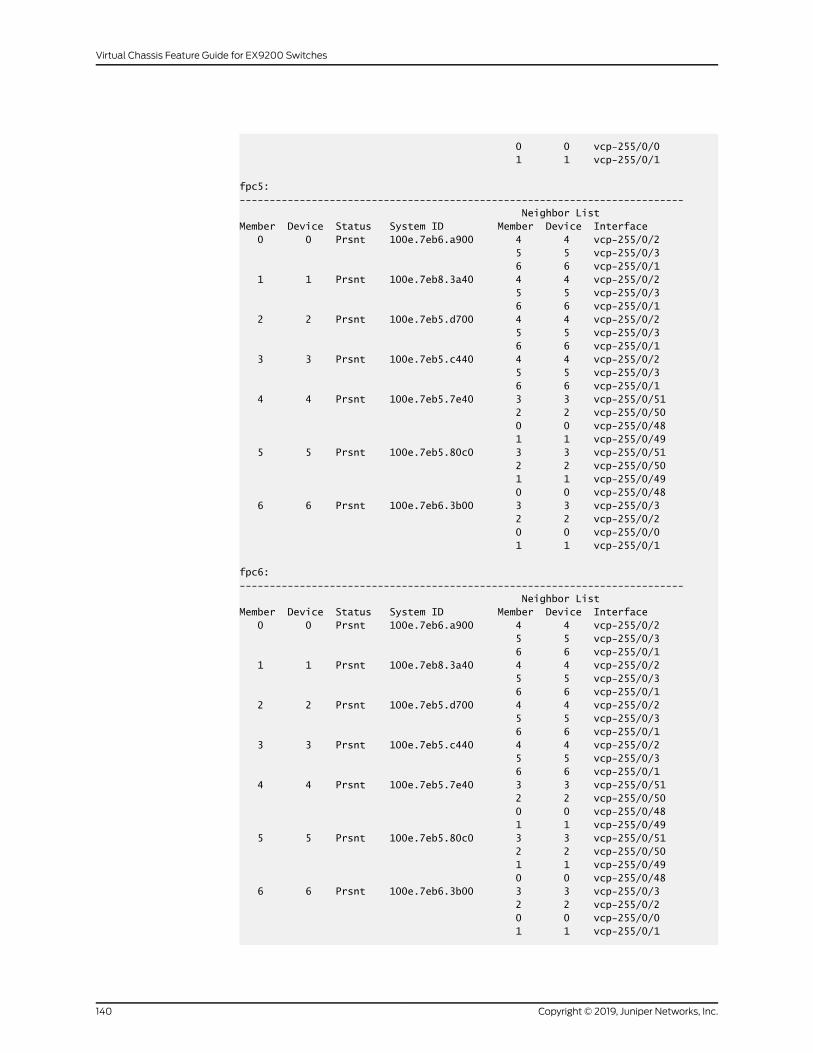
0 0 vcp-255/0/0 1 1 vcp-255/0/1
fpc5:-------------------------------------------------------------------------- Neighbor ListMember Device Status System ID Member Device Interface 0 0 Prsnt 100e.7eb6.a900 4 4 vcp-255/0/2 5 5 vcp-255/0/3 6 6 vcp-255/0/1 1 1 Prsnt 100e.7eb8.3a40 4 4 vcp-255/0/2 5 5 vcp-255/0/3 6 6 vcp-255/0/1 2 2 Prsnt 100e.7eb5.d700 4 4 vcp-255/0/2 5 5 vcp-255/0/3 6 6 vcp-255/0/1 3 3 Prsnt 100e.7eb5.c440 4 4 vcp-255/0/2 5 5 vcp-255/0/3 6 6 vcp-255/0/1 4 4 Prsnt 100e.7eb5.7e40 3 3 vcp-255/0/51 2 2 vcp-255/0/50 0 0 vcp-255/0/48 1 1 vcp-255/0/49 5 5 Prsnt 100e.7eb5.80c0 3 3 vcp-255/0/51 2 2 vcp-255/0/50 1 1 vcp-255/0/49 0 0 vcp-255/0/48 6 6 Prsnt 100e.7eb6.3b00 3 3 vcp-255/0/3 2 2 vcp-255/0/2 0 0 vcp-255/0/0 1 1 vcp-255/0/1
fpc6:-------------------------------------------------------------------------- Neighbor ListMember Device Status System ID Member Device Interface 0 0 Prsnt 100e.7eb6.a900 4 4 vcp-255/0/2 5 5 vcp-255/0/3 6 6 vcp-255/0/1 1 1 Prsnt 100e.7eb8.3a40 4 4 vcp-255/0/2 5 5 vcp-255/0/3 6 6 vcp-255/0/1 2 2 Prsnt 100e.7eb5.d700 4 4 vcp-255/0/2 5 5 vcp-255/0/3 6 6 vcp-255/0/1 3 3 Prsnt 100e.7eb5.c440 4 4 vcp-255/0/2 5 5 vcp-255/0/3 6 6 vcp-255/0/1 4 4 Prsnt 100e.7eb5.7e40 3 3 vcp-255/0/51 2 2 vcp-255/0/50 0 0 vcp-255/0/48 1 1 vcp-255/0/49 5 5 Prsnt 100e.7eb5.80c0 3 3 vcp-255/0/51 2 2 vcp-255/0/50 1 1 vcp-255/0/49 0 0 vcp-255/0/48 6 6 Prsnt 100e.7eb6.3b00 3 3 vcp-255/0/3 2 2 vcp-255/0/2 0 0 vcp-255/0/0 1 1 vcp-255/0/1
Copyright © 2019, Juniper Networks, Inc.140
Virtual Chassis Feature Guide for EX9200 Switches
141Copyright © 2019, Juniper Networks, Inc.
Chapter 13: Operational Commands: Monitoring
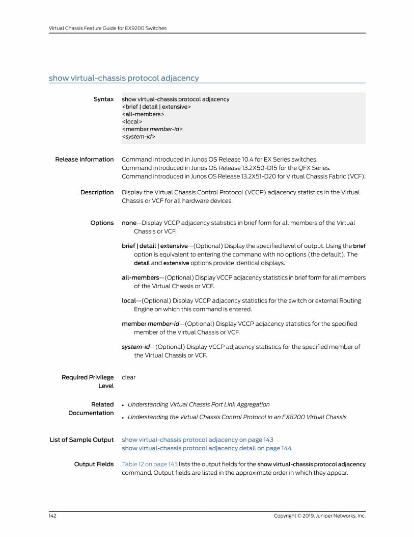
show virtual-chassis protocol adjacency
Syntax show virtual-chassis protocol adjacency<brief | detail | extensive><all-members><local><membermember-id><system-id>
Release Information Command introduced in Junos OS Release 10.4 for EX Series switches.
Command introduced in Junos OS Release 13.2X50-D15 for the QFX Series.
Command introduced in Junos OSRelease 13.2X51-D20 for Virtual Chassis Fabric (VCF).
Description Display the Virtual Chassis Control Protocol (VCCP) adjacency statistics in the Virtual
Chassis or VCF for all hardware devices.
Options none—Display VCCP adjacency statistics in brief form for all members of the Virtual
Chassis or VCF.
brief | detail | extensive—(Optional) Display the specified level of output. Using the briefoption is equivalent to entering the command with no options (the default). The
detail and extensive options provide identical displays.
all-members—(Optional)DisplayVCCPadjacency statistics inbrief formforallmembers
of the Virtual Chassis or VCF.
local—(Optional) Display VCCP adjacency statistics for the switch or external RoutingEngine on which this command is entered.
membermember-id—(Optional) Display VCCP adjacency statistics for the specifiedmember of the Virtual Chassis or VCF.
system-id—(Optional) Display VCCP adjacency statistics for the specified member ofthe Virtual Chassis or VCF.
Required PrivilegeLevel
clear
RelatedDocumentation
Understanding Virtual Chassis Port Link Aggregation•
• Understanding the Virtual Chassis Control Protocol in an EX8200 Virtual Chassis
List of Sample Output show virtual-chassis protocol adjacency on page 143show virtual-chassis protocol adjacency detail on page 144
Output Fields Table 12 onpage 143 lists the output fields for the showvirtual-chassisprotocol adjacency
command. Output fields are listed in the approximate order in which they appear.
Copyright © 2019, Juniper Networks, Inc.142
Virtual Chassis Feature Guide for EX9200 Switches
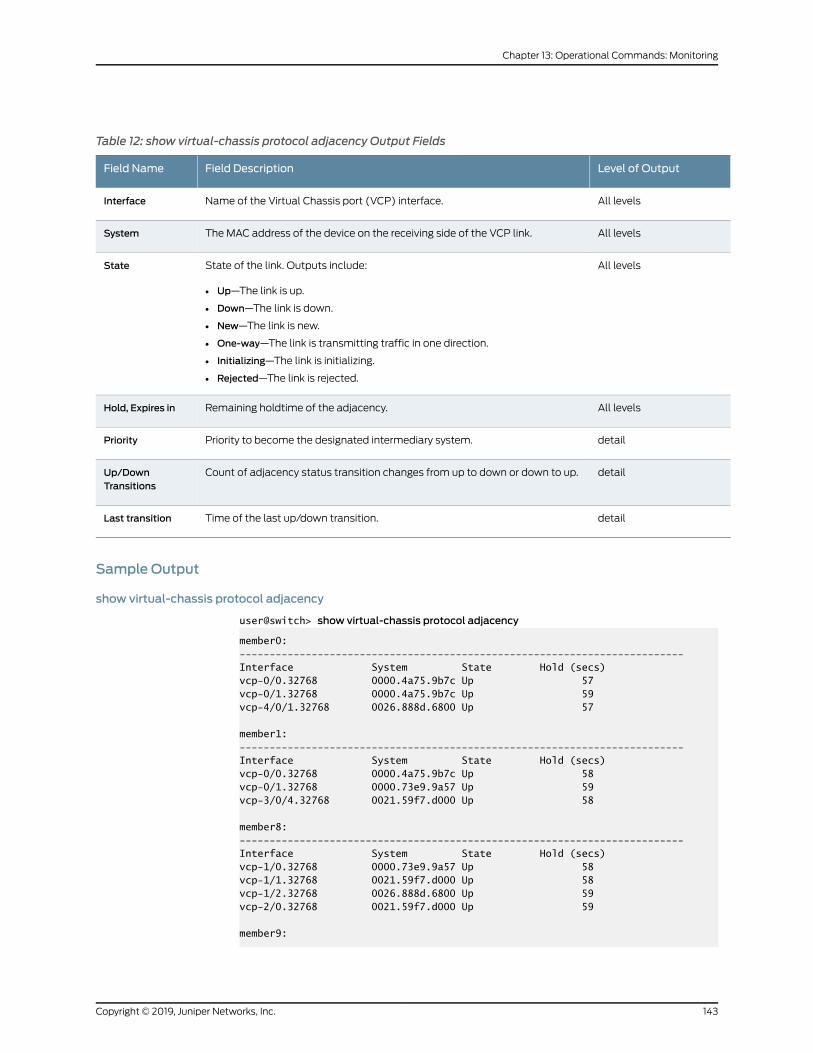
Table 12: show virtual-chassis protocol adjacency Output Fields
Level of OutputField DescriptionField Name
All levelsName of the Virtual Chassis port (VCP) interface.Interface
All levelsThe MAC address of the device on the receiving side of the VCP link.System
All levelsState of the link. Outputs include:
• Up—The link is up.
• Down—The link is down.
• New—The link is new.
• One-way—The link is transmitting traffic in one direction.
• Initializing—The link is initializing.
• Rejected—The link is rejected.
State
All levelsRemaining holdtime of the adjacency.Hold, Expires in
detailPriority to become the designated intermediary system.Priority
detailCount of adjacency status transition changes from up to down or down to up.Up/DownTransitions
detailTime of the last up/down transition.Last transition
Sample Output
show virtual-chassis protocol adjacency
user@switch> show virtual-chassis protocol adjacency
member0:--------------------------------------------------------------------------Interface System State Hold (secs)vcp-0/0.32768 0000.4a75.9b7c Up 57vcp-0/1.32768 0000.4a75.9b7c Up 59vcp-4/0/1.32768 0026.888d.6800 Up 57
member1:--------------------------------------------------------------------------Interface System State Hold (secs)vcp-0/0.32768 0000.4a75.9b7c Up 58vcp-0/1.32768 0000.73e9.9a57 Up 59vcp-3/0/4.32768 0021.59f7.d000 Up 58
member8:--------------------------------------------------------------------------Interface System State Hold (secs)vcp-1/0.32768 0000.73e9.9a57 Up 58vcp-1/1.32768 0021.59f7.d000 Up 58vcp-1/2.32768 0026.888d.6800 Up 59vcp-2/0.32768 0021.59f7.d000 Up 59
member9:
143Copyright © 2019, Juniper Networks, Inc.
Chapter 13: Operational Commands: Monitoring
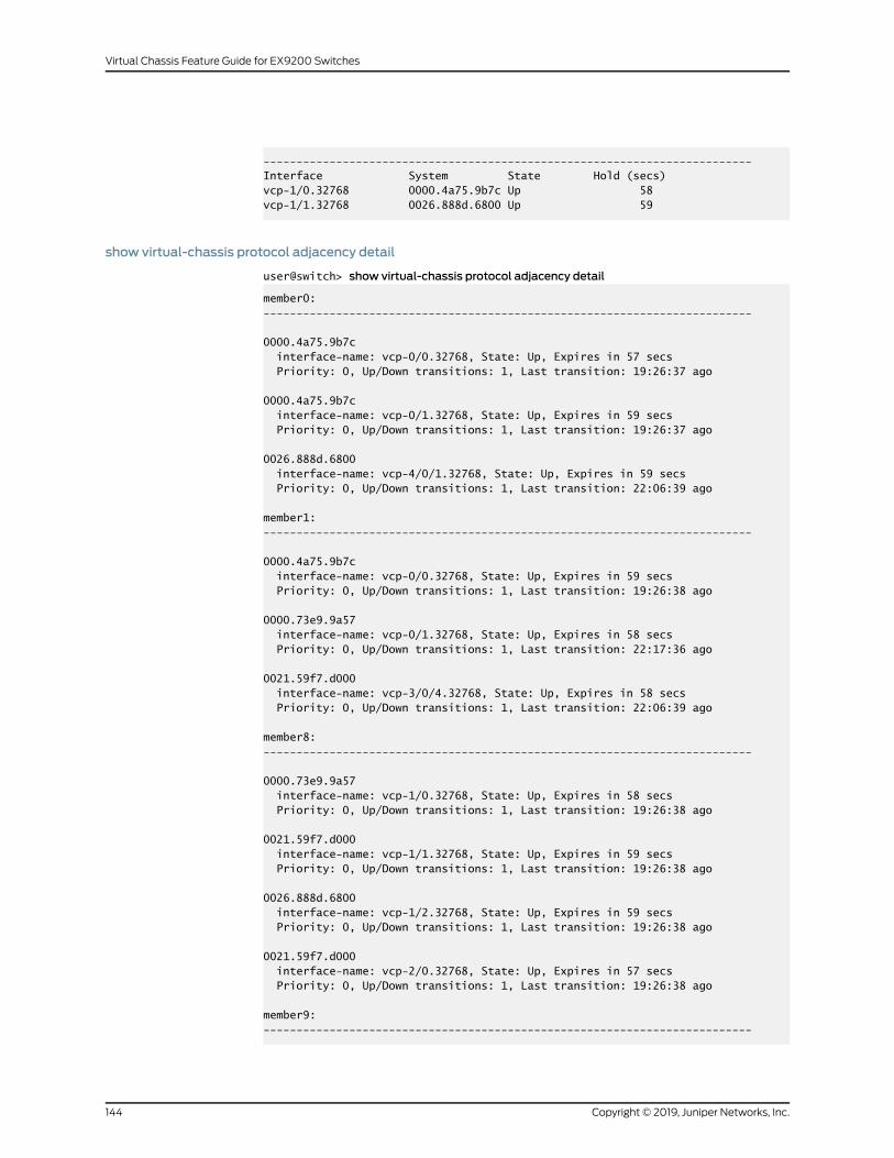
--------------------------------------------------------------------------Interface System State Hold (secs)vcp-1/0.32768 0000.4a75.9b7c Up 58vcp-1/1.32768 0026.888d.6800 Up 59
show virtual-chassis protocol adjacency detail
user@switch> show virtual-chassis protocol adjacency detail
member0:--------------------------------------------------------------------------
0000.4a75.9b7c interface-name: vcp-0/0.32768, State: Up, Expires in 57 secs Priority: 0, Up/Down transitions: 1, Last transition: 19:26:37 ago
0000.4a75.9b7c interface-name: vcp-0/1.32768, State: Up, Expires in 59 secs Priority: 0, Up/Down transitions: 1, Last transition: 19:26:37 ago
0026.888d.6800 interface-name: vcp-4/0/1.32768, State: Up, Expires in 59 secs Priority: 0, Up/Down transitions: 1, Last transition: 22:06:39 ago
member1:--------------------------------------------------------------------------
0000.4a75.9b7c interface-name: vcp-0/0.32768, State: Up, Expires in 59 secs Priority: 0, Up/Down transitions: 1, Last transition: 19:26:38 ago
0000.73e9.9a57 interface-name: vcp-0/1.32768, State: Up, Expires in 58 secs Priority: 0, Up/Down transitions: 1, Last transition: 22:17:36 ago
0021.59f7.d000 interface-name: vcp-3/0/4.32768, State: Up, Expires in 58 secs Priority: 0, Up/Down transitions: 1, Last transition: 22:06:39 ago
member8:--------------------------------------------------------------------------
0000.73e9.9a57 interface-name: vcp-1/0.32768, State: Up, Expires in 58 secs Priority: 0, Up/Down transitions: 1, Last transition: 19:26:38 ago
0021.59f7.d000 interface-name: vcp-1/1.32768, State: Up, Expires in 59 secs Priority: 0, Up/Down transitions: 1, Last transition: 19:26:38 ago
0026.888d.6800 interface-name: vcp-1/2.32768, State: Up, Expires in 59 secs Priority: 0, Up/Down transitions: 1, Last transition: 19:26:38 ago
0021.59f7.d000 interface-name: vcp-2/0.32768, State: Up, Expires in 57 secs Priority: 0, Up/Down transitions: 1, Last transition: 19:26:38 ago
member9:--------------------------------------------------------------------------
Copyright © 2019, Juniper Networks, Inc.144
Virtual Chassis Feature Guide for EX9200 Switches
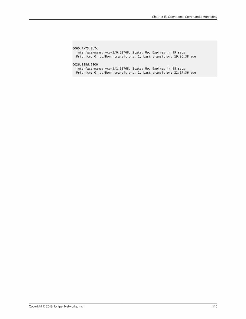
0000.4a75.9b7c interface-name: vcp-1/0.32768, State: Up, Expires in 59 secs Priority: 0, Up/Down transitions: 1, Last transition: 19:26:38 ago
0026.888d.6800 interface-name: vcp-1/1.32768, State: Up, Expires in 58 secs Priority: 0, Up/Down transitions: 1, Last transition: 22:17:36 ago
145Copyright © 2019, Juniper Networks, Inc.
Chapter 13: Operational Commands: Monitoring
show virtual-chassis protocol database
Syntax show virtual-chassis protocol database<brief | detail | extensive><all-members><local><membermember-id>
Release Information Command introduced in Junos OS Release 10.4 for EX Series switches.
Command introduced in Junos OS Release 13.2X50-D15 for the QFX Series.
Command introduced in Junos OSRelease 13.2X51-D20 for Virtual Chassis Fabric (VCF).
Description Display the Virtual Chassis Control Protocol (VCCP) database statistics for all hardware
devices within the Virtual Chassis or VCF.
Options none—Display VCCP database statistics in brief form for all members of the Virtual
Chassis or VCF.
brief | detail | extensive—(Optional) Display the specified level of output. Using the briefoption is equivalent to entering the command with no options (the default). The
detailoptionprovidesmoreoutput than thebriefoption.Theextensiveoptionprovides
all output and is most useful for customer support personnel.
all-members—(Optional)DisplayVCCPdatabase statistics inbrief form for allmembers
of the Virtual Chassis or VCF.
local—(Optional) Display VCCP database statistics for the switch or external RoutingEngine on which this command is entered.
membermember-id—(Optional) Display VCCP database statistics for the specifiedmember of the Virtual Chassis or VCF.
Required PrivilegeLevel
clear
RelatedDocumentation
Understanding the Virtual Chassis Control Protocol in an EX8200 Virtual Chassis•
• Understanding Virtual Chassis Components on page 16
List of Sample Output show virtual-chassis protocol database on page 147show virtual-chassis protocol database detail on page 148
Output Fields Table 13 on page 147 lists the output fields for the showvirtual-chassis protocol database
command. Output fields are listed in the approximate order in which they appear.
Copyright © 2019, Juniper Networks, Inc.146
Virtual Chassis Feature Guide for EX9200 Switches
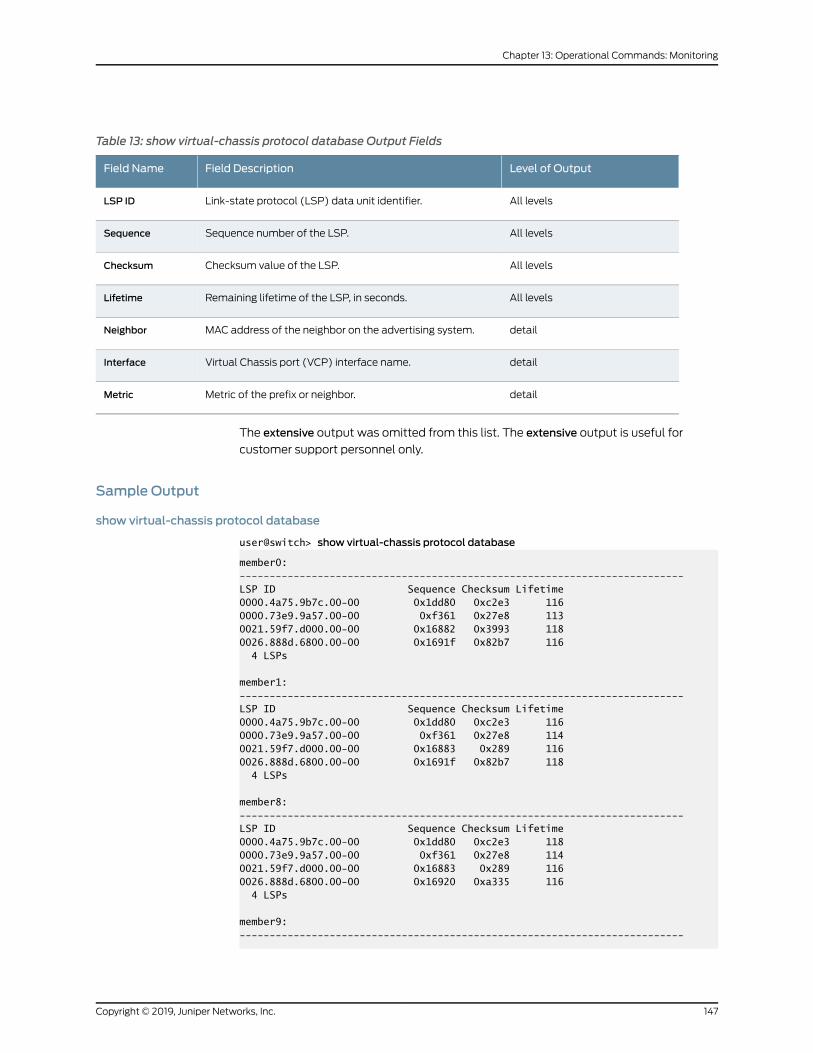
Table 13: show virtual-chassis protocol database Output Fields
Level of OutputField DescriptionField Name
All levelsLink-state protocol (LSP) data unit identifier.LSP ID
All levelsSequence number of the LSP.Sequence
All levelsChecksum value of the LSP.Checksum
All levelsRemaining lifetime of the LSP, in seconds.Lifetime
detailMAC address of the neighbor on the advertising system.Neighbor
detailVirtual Chassis port (VCP) interface name.Interface
detailMetric of the prefix or neighbor.Metric
The extensive output was omitted from this list. The extensive output is useful for
customer support personnel only.
Sample Output
show virtual-chassis protocol database
user@switch> show virtual-chassis protocol database
member0:--------------------------------------------------------------------------LSP ID Sequence Checksum Lifetime0000.4a75.9b7c.00-00 0x1dd80 0xc2e3 1160000.73e9.9a57.00-00 0xf361 0x27e8 1130021.59f7.d000.00-00 0x16882 0x3993 1180026.888d.6800.00-00 0x1691f 0x82b7 116 4 LSPs
member1:--------------------------------------------------------------------------LSP ID Sequence Checksum Lifetime0000.4a75.9b7c.00-00 0x1dd80 0xc2e3 1160000.73e9.9a57.00-00 0xf361 0x27e8 1140021.59f7.d000.00-00 0x16883 0x289 1160026.888d.6800.00-00 0x1691f 0x82b7 118 4 LSPs
member8:--------------------------------------------------------------------------LSP ID Sequence Checksum Lifetime0000.4a75.9b7c.00-00 0x1dd80 0xc2e3 1180000.73e9.9a57.00-00 0xf361 0x27e8 1140021.59f7.d000.00-00 0x16883 0x289 1160026.888d.6800.00-00 0x16920 0xa335 116 4 LSPs
member9:--------------------------------------------------------------------------
147Copyright © 2019, Juniper Networks, Inc.
Chapter 13: Operational Commands: Monitoring
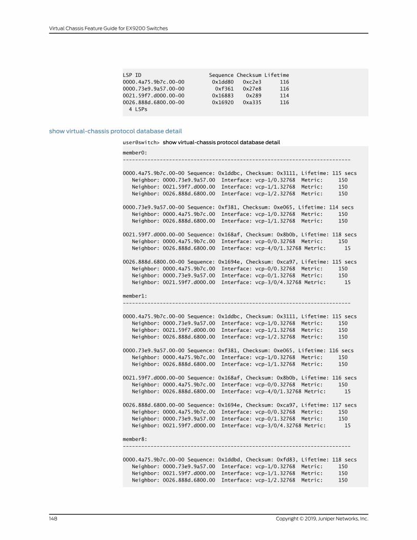
LSP ID Sequence Checksum Lifetime0000.4a75.9b7c.00-00 0x1dd80 0xc2e3 1160000.73e9.9a57.00-00 0xf361 0x27e8 1160021.59f7.d000.00-00 0x16883 0x289 1140026.888d.6800.00-00 0x16920 0xa335 116 4 LSPs
show virtual-chassis protocol database detail
user@switch> show virtual-chassis protocol database detail
member0:--------------------------------------------------------------------------
0000.4a75.9b7c.00-00 Sequence: 0x1ddbc, Checksum: 0x3111, Lifetime: 115 secs Neighbor: 0000.73e9.9a57.00 Interface: vcp-1/0.32768 Metric: 150 Neighbor: 0021.59f7.d000.00 Interface: vcp-1/1.32768 Metric: 150 Neighbor: 0026.888d.6800.00 Interface: vcp-1/2.32768 Metric: 150
0000.73e9.9a57.00-00 Sequence: 0xf381, Checksum: 0xe065, Lifetime: 114 secs Neighbor: 0000.4a75.9b7c.00 Interface: vcp-1/0.32768 Metric: 150 Neighbor: 0026.888d.6800.00 Interface: vcp-1/1.32768 Metric: 150
0021.59f7.d000.00-00 Sequence: 0x168af, Checksum: 0x8b0b, Lifetime: 118 secs Neighbor: 0000.4a75.9b7c.00 Interface: vcp-0/0.32768 Metric: 150 Neighbor: 0026.888d.6800.00 Interface: vcp-4/0/1.32768 Metric: 15
0026.888d.6800.00-00 Sequence: 0x1694e, Checksum: 0xca97, Lifetime: 115 secs Neighbor: 0000.4a75.9b7c.00 Interface: vcp-0/0.32768 Metric: 150 Neighbor: 0000.73e9.9a57.00 Interface: vcp-0/1.32768 Metric: 150 Neighbor: 0021.59f7.d000.00 Interface: vcp-3/0/4.32768 Metric: 15
member1:--------------------------------------------------------------------------
0000.4a75.9b7c.00-00 Sequence: 0x1ddbc, Checksum: 0x3111, Lifetime: 115 secs Neighbor: 0000.73e9.9a57.00 Interface: vcp-1/0.32768 Metric: 150 Neighbor: 0021.59f7.d000.00 Interface: vcp-1/1.32768 Metric: 150 Neighbor: 0026.888d.6800.00 Interface: vcp-1/2.32768 Metric: 150
0000.73e9.9a57.00-00 Sequence: 0xf381, Checksum: 0xe065, Lifetime: 116 secs Neighbor: 0000.4a75.9b7c.00 Interface: vcp-1/0.32768 Metric: 150 Neighbor: 0026.888d.6800.00 Interface: vcp-1/1.32768 Metric: 150
0021.59f7.d000.00-00 Sequence: 0x168af, Checksum: 0x8b0b, Lifetime: 116 secs Neighbor: 0000.4a75.9b7c.00 Interface: vcp-0/0.32768 Metric: 150 Neighbor: 0026.888d.6800.00 Interface: vcp-4/0/1.32768 Metric: 15
0026.888d.6800.00-00 Sequence: 0x1694e, Checksum: 0xca97, Lifetime: 117 secs Neighbor: 0000.4a75.9b7c.00 Interface: vcp-0/0.32768 Metric: 150 Neighbor: 0000.73e9.9a57.00 Interface: vcp-0/1.32768 Metric: 150 Neighbor: 0021.59f7.d000.00 Interface: vcp-3/0/4.32768 Metric: 15
member8:--------------------------------------------------------------------------
0000.4a75.9b7c.00-00 Sequence: 0x1ddbd, Checksum: 0xfd83, Lifetime: 118 secs Neighbor: 0000.73e9.9a57.00 Interface: vcp-1/0.32768 Metric: 150 Neighbor: 0021.59f7.d000.00 Interface: vcp-1/1.32768 Metric: 150 Neighbor: 0026.888d.6800.00 Interface: vcp-1/2.32768 Metric: 150
Copyright © 2019, Juniper Networks, Inc.148
Virtual Chassis Feature Guide for EX9200 Switches
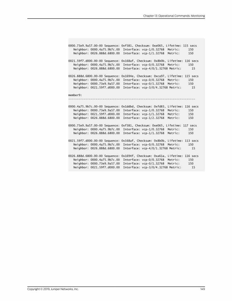
0000.73e9.9a57.00-00 Sequence: 0xf381, Checksum: 0xe065, Lifetime: 115 secs Neighbor: 0000.4a75.9b7c.00 Interface: vcp-1/0.32768 Metric: 150 Neighbor: 0026.888d.6800.00 Interface: vcp-1/1.32768 Metric: 150
0021.59f7.d000.00-00 Sequence: 0x168af, Checksum: 0x8b0b, Lifetime: 116 secs Neighbor: 0000.4a75.9b7c.00 Interface: vcp-0/0.32768 Metric: 150 Neighbor: 0026.888d.6800.00 Interface: vcp-4/0/1.32768 Metric: 15
0026.888d.6800.00-00 Sequence: 0x1694e, Checksum: 0xca97, Lifetime: 115 secs Neighbor: 0000.4a75.9b7c.00 Interface: vcp-0/0.32768 Metric: 150 Neighbor: 0000.73e9.9a57.00 Interface: vcp-0/1.32768 Metric: 150 Neighbor: 0021.59f7.d000.00 Interface: vcp-3/0/4.32768 Metric: 15
member9:--------------------------------------------------------------------------
0000.4a75.9b7c.00-00 Sequence: 0x1ddbd, Checksum: 0xfd83, Lifetime: 116 secs Neighbor: 0000.73e9.9a57.00 Interface: vcp-1/0.32768 Metric: 150 Neighbor: 0021.59f7.d000.00 Interface: vcp-1/1.32768 Metric: 150 Neighbor: 0026.888d.6800.00 Interface: vcp-1/2.32768 Metric: 150
0000.73e9.9a57.00-00 Sequence: 0xf381, Checksum: 0xe065, Lifetime: 117 secs Neighbor: 0000.4a75.9b7c.00 Interface: vcp-1/0.32768 Metric: 150 Neighbor: 0026.888d.6800.00 Interface: vcp-1/1.32768 Metric: 150
0021.59f7.d000.00-00 Sequence: 0x168af, Checksum: 0x8b0b, Lifetime: 113 secs Neighbor: 0000.4a75.9b7c.00 Interface: vcp-0/0.32768 Metric: 150 Neighbor: 0026.888d.6800.00 Interface: vcp-4/0/1.32768 Metric: 15
0026.888d.6800.00-00 Sequence: 0x1694f, Checksum: 0xa61a, Lifetime: 116 secs Neighbor: 0000.4a75.9b7c.00 Interface: vcp-0/0.32768 Metric: 150 Neighbor: 0000.73e9.9a57.00 Interface: vcp-0/1.32768 Metric: 150 Neighbor: 0021.59f7.d000.00 Interface: vcp-3/0/4.32768 Metric: 15
149Copyright © 2019, Juniper Networks, Inc.
Chapter 13: Operational Commands: Monitoring
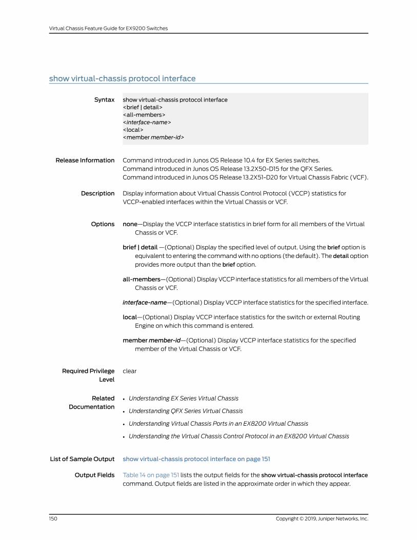
show virtual-chassis protocol interface
Syntax show virtual-chassis protocol interface<brief | detail><all-members><interface-name><local><membermember-id>
Release Information Command introduced in Junos OS Release 10.4 for EX Series switches.
Command introduced in Junos OS Release 13.2X50-D15 for the QFX Series.
Command introduced in Junos OSRelease 13.2X51-D20 for Virtual Chassis Fabric (VCF).
Description Display information about Virtual Chassis Control Protocol (VCCP) statistics for
VCCP-enabled interfaces within the Virtual Chassis or VCF.
Options none—Display the VCCP interface statistics in brief form for all members of the Virtual
Chassis or VCF.
brief | detail—(Optional) Display the specified level of output. Using the brief option isequivalent to entering the commandwith no options (the default). The detailoption
provides more output than the brief option.
all-members—(Optional)DisplayVCCP interface statistics for allmembersof theVirtualChassis or VCF.
interface-name—(Optional) Display VCCP interface statistics for the specified interface.
local—(Optional) Display VCCP interface statistics for the switch or external RoutingEngine on which this command is entered.
membermember-id—(Optional) Display VCCP interface statistics for the specifiedmember of the Virtual Chassis or VCF.
Required PrivilegeLevel
clear
RelatedDocumentation
Understanding EX Series Virtual Chassis•
• Understanding QFX Series Virtual Chassis
• Understanding Virtual Chassis Ports in an EX8200 Virtual Chassis
• Understanding the Virtual Chassis Control Protocol in an EX8200 Virtual Chassis
List of Sample Output show virtual-chassis protocol interface on page 151
Output Fields Table 14 on page 151 lists the output fields for the show virtual-chassis protocol interface
command. Output fields are listed in the approximate order in which they appear.
Copyright © 2019, Juniper Networks, Inc.150
Virtual Chassis Feature Guide for EX9200 Switches
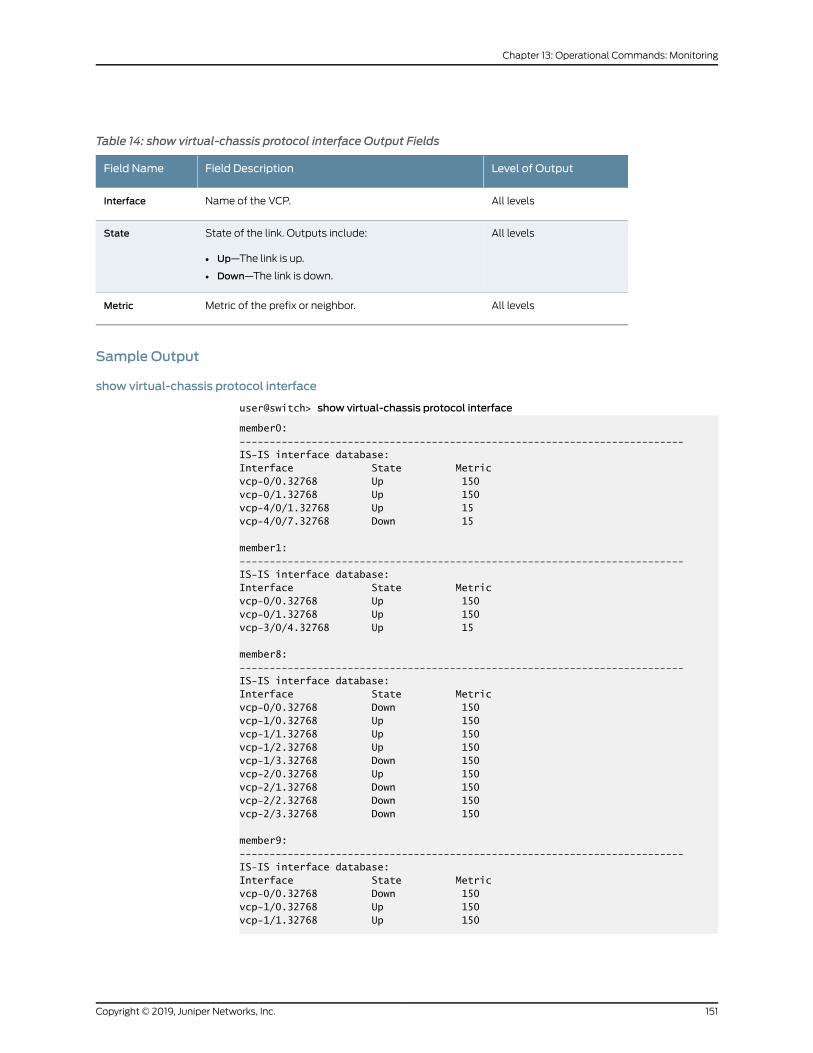
Table 14: show virtual-chassis protocol interface Output Fields
Level of OutputField DescriptionField Name
All levelsName of the VCP.Interface
All levelsState of the link. Outputs include:
• Up—The link is up.
• Down—The link is down.
State
All levelsMetric of the prefix or neighbor.Metric
Sample Output
show virtual-chassis protocol interface
user@switch> show virtual-chassis protocol interface
member0:--------------------------------------------------------------------------IS-IS interface database:Interface State Metricvcp-0/0.32768 Up 150vcp-0/1.32768 Up 150vcp-4/0/1.32768 Up 15vcp-4/0/7.32768 Down 15
member1:--------------------------------------------------------------------------IS-IS interface database:Interface State Metricvcp-0/0.32768 Up 150vcp-0/1.32768 Up 150vcp-3/0/4.32768 Up 15
member8:--------------------------------------------------------------------------IS-IS interface database:Interface State Metricvcp-0/0.32768 Down 150vcp-1/0.32768 Up 150vcp-1/1.32768 Up 150vcp-1/2.32768 Up 150vcp-1/3.32768 Down 150vcp-2/0.32768 Up 150vcp-2/1.32768 Down 150vcp-2/2.32768 Down 150vcp-2/3.32768 Down 150
member9:--------------------------------------------------------------------------IS-IS interface database:Interface State Metricvcp-0/0.32768 Down 150vcp-1/0.32768 Up 150vcp-1/1.32768 Up 150
151Copyright © 2019, Juniper Networks, Inc.
Chapter 13: Operational Commands: Monitoring
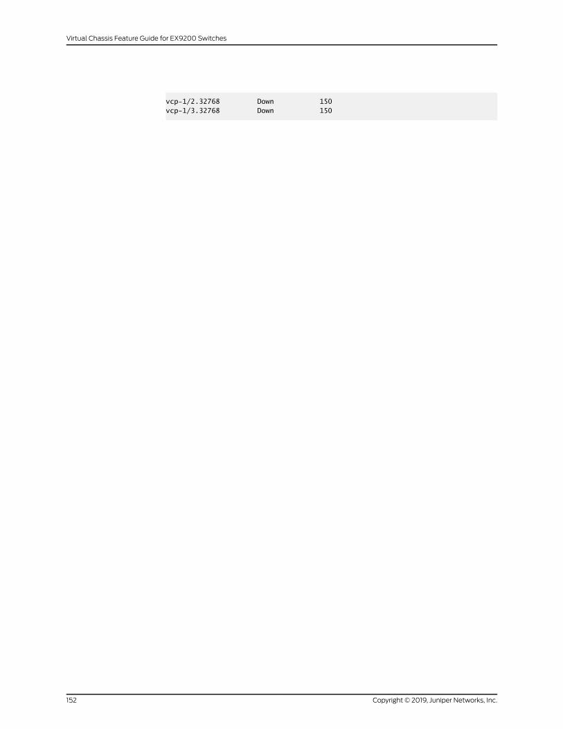
vcp-1/2.32768 Down 150vcp-1/3.32768 Down 150
Copyright © 2019, Juniper Networks, Inc.152
Virtual Chassis Feature Guide for EX9200 Switches
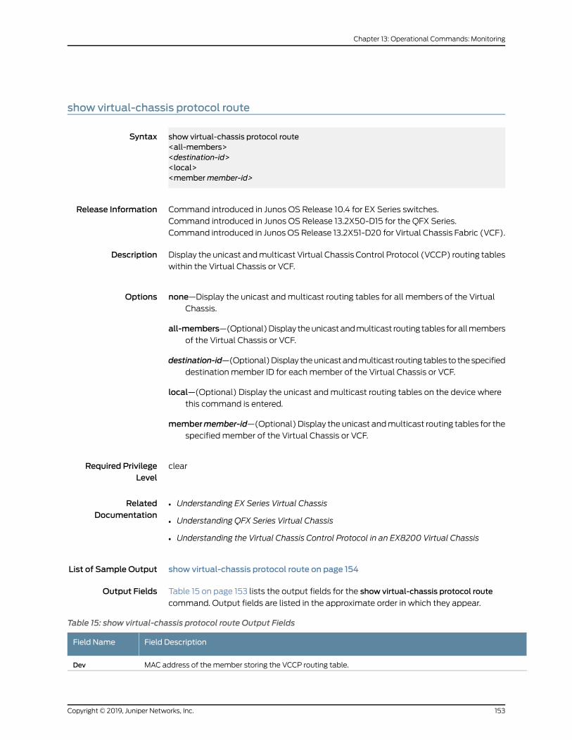
show virtual-chassis protocol route
Syntax show virtual-chassis protocol route<all-members><destination-id><local><membermember-id>
Release Information Command introduced in Junos OS Release 10.4 for EX Series switches.
Command introduced in Junos OS Release 13.2X50-D15 for the QFX Series.
Command introduced in Junos OSRelease 13.2X51-D20 for Virtual Chassis Fabric (VCF).
Description Display the unicast andmulticast Virtual Chassis Control Protocol (VCCP) routing tables
within the Virtual Chassis or VCF.
Options none—Display the unicast andmulticast routing tables for all members of the VirtualChassis.
all-members—(Optional)Display theunicastandmulticast routing tables forallmembersof the Virtual Chassis or VCF.
destination-id—(Optional)Display theunicastandmulticast routing tables to thespecifieddestination member ID for eachmember of the Virtual Chassis or VCF.
local—(Optional) Display the unicast andmulticast routing tables on the device wherethis command is entered.
membermember-id—(Optional) Display the unicast andmulticast routing tables for thespecified member of the Virtual Chassis or VCF.
Required PrivilegeLevel
clear
RelatedDocumentation
Understanding EX Series Virtual Chassis•
• Understanding QFX Series Virtual Chassis
• Understanding the Virtual Chassis Control Protocol in an EX8200 Virtual Chassis
List of Sample Output show virtual-chassis protocol route on page 154
Output Fields Table 15 on page 153 lists the output fields for the show virtual-chassis protocol route
command. Output fields are listed in the approximate order in which they appear.
Table 15: show virtual-chassis protocol route Output Fields
Field DescriptionField Name
MAC address of the member storing the VCCP routing table.Dev
153Copyright © 2019, Juniper Networks, Inc.
Chapter 13: Operational Commands: Monitoring
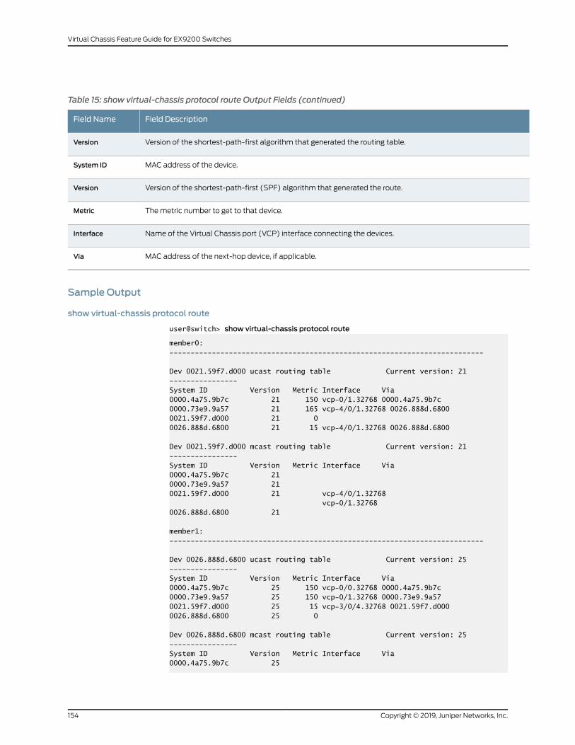
Table 15: show virtual-chassis protocol route Output Fields (continued)
Field DescriptionField Name
Version of the shortest-path-first algorithm that generated the routing table.Version
MAC address of the device.System ID
Version of the shortest-path-first (SPF) algorithm that generated the route.Version
Themetric number to get to that device.Metric
Name of the Virtual Chassis port (VCP) interface connecting the devices.Interface
MAC address of the next-hop device, if applicable.Via
Sample Output
show virtual-chassis protocol route
user@switch> show virtual-chassis protocol route
member0:--------------------------------------------------------------------------
Dev 0021.59f7.d000 ucast routing table Current version: 21----------------System ID Version Metric Interface Via0000.4a75.9b7c 21 150 vcp-0/1.32768 0000.4a75.9b7c0000.73e9.9a57 21 165 vcp-4/0/1.32768 0026.888d.68000021.59f7.d000 21 00026.888d.6800 21 15 vcp-4/0/1.32768 0026.888d.6800
Dev 0021.59f7.d000 mcast routing table Current version: 21----------------System ID Version Metric Interface Via0000.4a75.9b7c 210000.73e9.9a57 210021.59f7.d000 21 vcp-4/0/1.32768 vcp-0/1.327680026.888d.6800 21
member1:--------------------------------------------------------------------------
Dev 0026.888d.6800 ucast routing table Current version: 25----------------System ID Version Metric Interface Via0000.4a75.9b7c 25 150 vcp-0/0.32768 0000.4a75.9b7c0000.73e9.9a57 25 150 vcp-0/1.32768 0000.73e9.9a570021.59f7.d000 25 15 vcp-3/0/4.32768 0021.59f7.d0000026.888d.6800 25 0
Dev 0026.888d.6800 mcast routing table Current version: 25----------------System ID Version Metric Interface Via0000.4a75.9b7c 25
Copyright © 2019, Juniper Networks, Inc.154
Virtual Chassis Feature Guide for EX9200 Switches
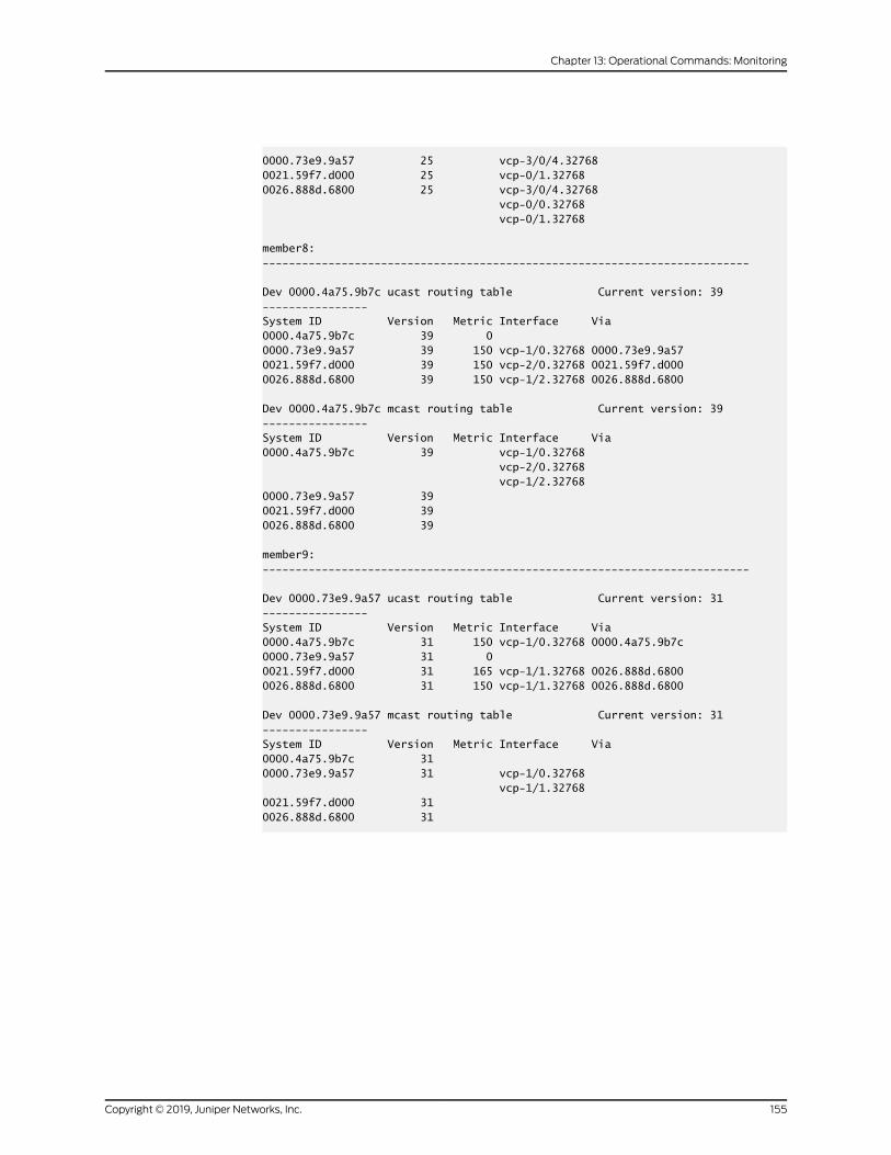
0000.73e9.9a57 25 vcp-3/0/4.327680021.59f7.d000 25 vcp-0/1.327680026.888d.6800 25 vcp-3/0/4.32768 vcp-0/0.32768 vcp-0/1.32768
member8:--------------------------------------------------------------------------
Dev 0000.4a75.9b7c ucast routing table Current version: 39----------------System ID Version Metric Interface Via0000.4a75.9b7c 39 00000.73e9.9a57 39 150 vcp-1/0.32768 0000.73e9.9a570021.59f7.d000 39 150 vcp-2/0.32768 0021.59f7.d0000026.888d.6800 39 150 vcp-1/2.32768 0026.888d.6800
Dev 0000.4a75.9b7c mcast routing table Current version: 39----------------System ID Version Metric Interface Via0000.4a75.9b7c 39 vcp-1/0.32768 vcp-2/0.32768 vcp-1/2.327680000.73e9.9a57 390021.59f7.d000 390026.888d.6800 39
member9:--------------------------------------------------------------------------
Dev 0000.73e9.9a57 ucast routing table Current version: 31----------------System ID Version Metric Interface Via0000.4a75.9b7c 31 150 vcp-1/0.32768 0000.4a75.9b7c0000.73e9.9a57 31 00021.59f7.d000 31 165 vcp-1/1.32768 0026.888d.68000026.888d.6800 31 150 vcp-1/1.32768 0026.888d.6800
Dev 0000.73e9.9a57 mcast routing table Current version: 31----------------System ID Version Metric Interface Via0000.4a75.9b7c 310000.73e9.9a57 31 vcp-1/0.32768 vcp-1/1.327680021.59f7.d000 310026.888d.6800 31
155Copyright © 2019, Juniper Networks, Inc.
Chapter 13: Operational Commands: Monitoring
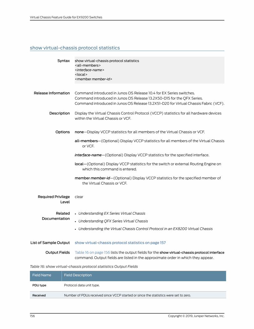
show virtual-chassis protocol statistics
Syntax show virtual-chassis protocol statistics<all-members><interface-name><local><membermember-id>
Release Information Command introduced in Junos OS Release 10.4 for EX Series switches.
Command introduced in Junos OS Release 13.2X50-D15 for the QFX Series.
Command introduced in Junos OSRelease 13.2X51-D20 for Virtual Chassis Fabric (VCF).
Description Display the Virtual Chassis Control Protocol (VCCP) statistics for all hardware devices
within the Virtual Chassis or VCF.
Options none—Display VCCP statistics for all members of the Virtual Chassis or VCF.
all-members—(Optional) Display VCCP statistics for all members of the Virtual Chassisor VCF.
interface-name—(Optional) Display VCCP statistics for the specified interface.
local—(Optional) Display VCCP statistics for the switch or external Routing Engine onwhich this command is entered.
membermember-id—(Optional) Display VCCP statistics for the specified member ofthe Virtual Chassis or VCF.
Required PrivilegeLevel
clear
RelatedDocumentation
Understanding EX Series Virtual Chassis•
• Understanding QFX Series Virtual Chassis
• Understanding the Virtual Chassis Control Protocol in an EX8200 Virtual Chassis
List of Sample Output show virtual-chassis protocol statistics on page 157
Output Fields Table 16 on page 156 lists the output fields for the show virtual-chassis protocol interface
command. Output fields are listed in the approximate order in which they appear.
Table 16: show virtual-chassis protocol statistics Output Fields
Field DescriptionField Name
Protocol data unit type.PDU type
Number of PDUs received since VCCP started or since the statistics were set to zero.Received
Copyright © 2019, Juniper Networks, Inc.156
Virtual Chassis Feature Guide for EX9200 Switches
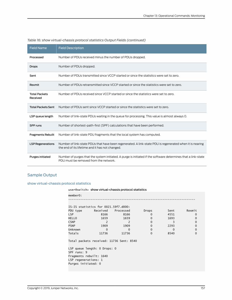
Table 16: show virtual-chassis protocol statistics Output Fields (continued)
Field DescriptionField Name
Number of PDUs receivedminus the number of PDUs dropped.Processed
Number of PDUs dropped.Drops
Number of PDUs transmitted since VCCP started or since the statistics were set to zero.Sent
Number of PDUs retransmitted since VCCP started or since the statistics were set to zero.Rexmit
Number of PDUs received since VCCP started or since the statistics were set to zero.Total PacketsReceived
Number of PDUs sent since VCCP started or since the statistics were set to zero.TotalPacketsSent
Number of link-state PDUs waiting in the queue for processing. This value is almost always 0.LSP queue length
Number of shortest-path-first (SPF) calculations that have been performed.SPF runs
Number of link-state PDU fragments that the local system has computed.Fragments Rebuilt
Number of link-state PDUs that have been regenerated. A link-state PDU is regenerated when it is nearingthe end of its lifetime and it has not changed.
LSPRegenerations
Number of purges that the system initiated. A purge is initiated if the software determines that a link-statePDUmust be removed from the network.
Purges initiated
Sample Output
show virtual-chassis protocol statistics
user@switch> show virtual-chassis protocol statistics
member0:--------------------------------------------------------------------------
IS-IS statistics for 0021.59f7.d000:PDU type Received Processed Drops Sent RexmitLSP 8166 8166 0 4551 0HELLO 1659 1659 0 1693 0CSNP 2 2 0 3 0PSNP 1909 1909 0 2293 0Unknown 0 0 0 0 0Totals 11736 11736 0 8540 0
Total packets received: 11736 Sent: 8540
LSP queue length: 0 Drops: 0SPF runs: 9Fragments rebuilt: 1640LSP regenerations: 1Purges initiated: 0
157Copyright © 2019, Juniper Networks, Inc.
Chapter 13: Operational Commands: Monitoring
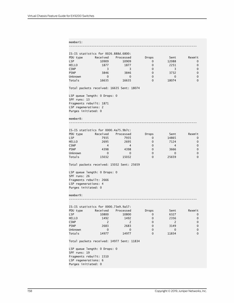
member1:--------------------------------------------------------------------------
IS-IS statistics for 0026.888d.6800:PDU type Received Processed Drops Sent RexmitLSP 10909 10909 0 12088 0HELLO 1877 1877 0 2251 0CSNP 3 3 0 3 0PSNP 3846 3846 0 3732 0Unknown 0 0 0 0 0Totals 16635 16635 0 18074 0
Total packets received: 16635 Sent: 18074
LSP queue length: 0 Drops: 0SPF runs: 13Fragments rebuilt: 1871LSP regenerations: 2Purges initiated: 0
member8:--------------------------------------------------------------------------
IS-IS statistics for 0000.4a75.9b7c:PDU type Received Processed Drops Sent RexmitLSP 7935 7935 0 14865 0HELLO 2695 2695 0 7124 0CSNP 4 4 0 4 0PSNP 4398 4398 0 3666 0Unknown 0 0 0 0 0Totals 15032 15032 0 25659 0
Total packets received: 15032 Sent: 25659
LSP queue length: 0 Drops: 0SPF runs: 26Fragments rebuilt: 2666LSP regenerations: 4Purges initiated: 0
member9:--------------------------------------------------------------------------
IS-IS statistics for 0000.73e9.9a57:PDU type Received Processed Drops Sent RexmitLSP 10800 10800 0 6327 0HELLO 1492 1492 0 2356 0CSNP 2 2 0 2 0PSNP 2683 2683 0 3149 0Unknown 0 0 0 0 0Totals 14977 14977 0 11834 0
Total packets received: 14977 Sent: 11834
LSP queue length: 0 Drops: 0SPF runs: 19Fragments rebuilt: 1510LSP regenerations: 6Purges initiated: 0
Copyright © 2019, Juniper Networks, Inc.158
Virtual Chassis Feature Guide for EX9200 Switches
159Copyright © 2019, Juniper Networks, Inc.
Chapter 13: Operational Commands: Monitoring
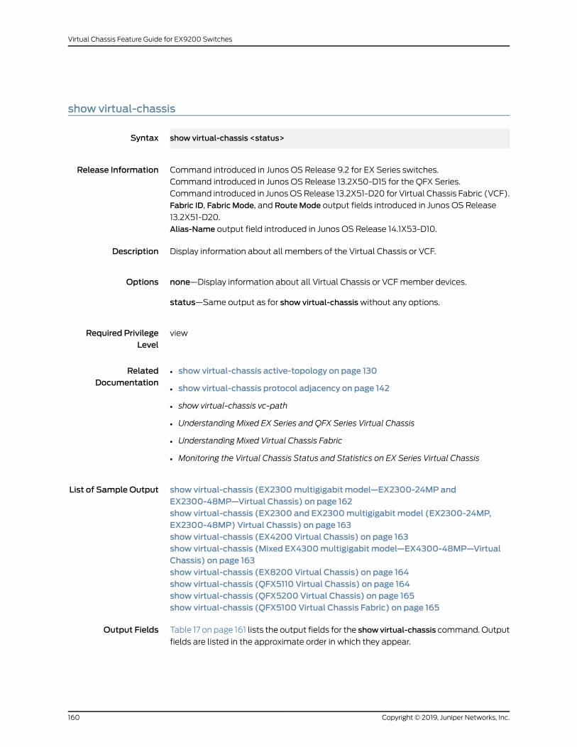
show virtual-chassis
Syntax show virtual-chassis <status>
Release Information Command introduced in Junos OS Release 9.2 for EX Series switches.
Command introduced in Junos OS Release 13.2X50-D15 for the QFX Series.
Command introduced in Junos OSRelease 13.2X51-D20 for Virtual Chassis Fabric (VCF).
Fabric ID, Fabric Mode, and RouteMode output fields introduced in Junos OS Release
13.2X51-D20.
Alias-Name output field introduced in Junos OS Release 14.1X53-D10.
Description Display information about all members of the Virtual Chassis or VCF.
Options none—Display information about all Virtual Chassis or VCFmember devices.
status—Same output as for show virtual-chassiswithout any options.
Required PrivilegeLevel
view
RelatedDocumentation
show virtual-chassis active-topology on page 130•
• show virtual-chassis protocol adjacency on page 142
• show virtual-chassis vc-path
• Understanding Mixed EX Series and QFX Series Virtual Chassis
• Understanding Mixed Virtual Chassis Fabric
• Monitoring the Virtual Chassis Status and Statistics on EX Series Virtual Chassis
List of Sample Output show virtual-chassis (EX2300multigigabit model—EX2300-24MP andEX2300-48MP—Virtual Chassis) on page 162show virtual-chassis (EX2300 and EX2300multigigabit model (EX2300-24MP,EX2300-48MP) Virtual Chassis) on page 163show virtual-chassis (EX4200 Virtual Chassis) on page 163show virtual-chassis (Mixed EX4300multigigabit model—EX4300-48MP—VirtualChassis) on page 163show virtual-chassis (EX8200 Virtual Chassis) on page 164show virtual-chassis (QFX5110 Virtual Chassis) on page 164show virtual-chassis (QFX5200 Virtual Chassis) on page 165show virtual-chassis (QFX5100 Virtual Chassis Fabric) on page 165
Output Fields Table 17 on page 161 lists the output fields for the showvirtual-chassis command. Output
fields are listed in the approximate order in which they appear.
Copyright © 2019, Juniper Networks, Inc.160
Virtual Chassis Feature Guide for EX9200 Switches
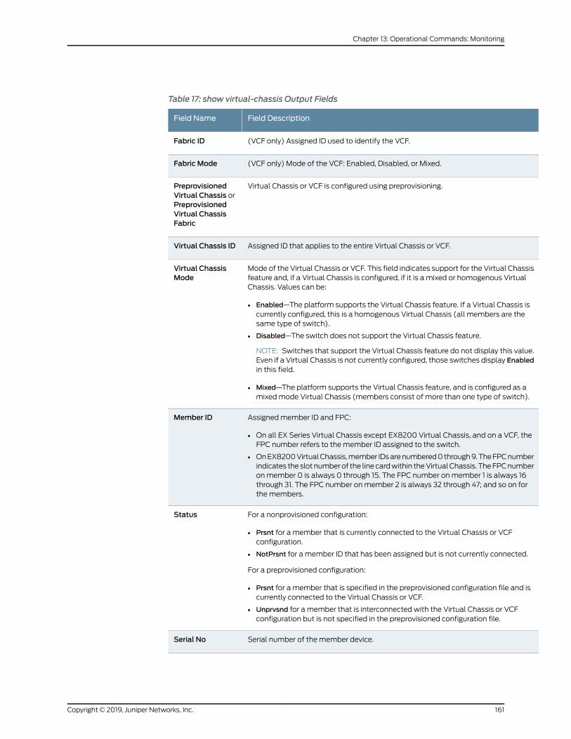
Table 17: show virtual-chassis Output Fields
Field DescriptionField Name
(VCF only) Assigned ID used to identify the VCF.Fabric ID
(VCF only) Mode of the VCF: Enabled, Disabled, or Mixed.Fabric Mode
Virtual Chassis or VCF is configured using preprovisioning.PreprovisionedVirtual Chassis orPreprovisionedVirtual ChassisFabric
Assigned ID that applies to the entire Virtual Chassis or VCF.Virtual Chassis ID
Mode of the Virtual Chassis or VCF. This field indicates support for the Virtual Chassisfeature and, if a Virtual Chassis is configured, if it is a mixed or homogenous VirtualChassis. Values can be:
• Enabled—The platform supports the Virtual Chassis feature. If a Virtual Chassis iscurrently configured, this is a homogenous Virtual Chassis (all members are thesame type of switch).
• Disabled—The switch does not support the Virtual Chassis feature.
NOTE: Switches that support the Virtual Chassis feature do not display this value.Even if a Virtual Chassis is not currently configured, those switches display Enabledin this field.
• Mixed—The platform supports the Virtual Chassis feature, and is configured as amixedmode Virtual Chassis (members consist of more than one type of switch).
Virtual ChassisMode
Assignedmember ID and FPC:
• On all EX Series Virtual Chassis except EX8200 Virtual Chassis, and on a VCF, theFPC number refers to the member ID assigned to the switch.
• OnEX8200VirtualChassis,member IDsarenumbered0through9.TheFPCnumberindicates the slot numberof the linecardwithin theVirtualChassis. TheFPCnumberonmember 0 is always 0 through 15. The FPC number onmember 1 is always 16through 31. The FPC number onmember 2 is always 32 through 47; and so on forthe members.
Member ID
For a nonprovisioned configuration:
• Prsnt for a member that is currently connected to the Virtual Chassis or VCFconfiguration.
• NotPrsnt for a member ID that has been assigned but is not currently connected.
For a preprovisioned configuration:
• Prsnt for a member that is specified in the preprovisioned configuration file and iscurrently connected to the Virtual Chassis or VCF.
• Unprvsnd for a member that is interconnected with the Virtual Chassis or VCFconfiguration but is not specified in the preprovisioned configuration file.
Status
Serial number of the member device.Serial No
161Copyright © 2019, Juniper Networks, Inc.
Chapter 13: Operational Commands: Monitoring
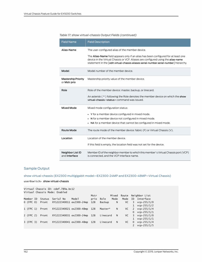
Table 17: show virtual-chassis Output Fields (continued)
Field DescriptionField Name
The user-configured alias of the member device.
The Alias-Name field appears only if an alias has been configured for at least onedevice in the Virtual Chassis or VCF. Aliases are configured using the alias-namestatement in the [edit virtual-chassis aliases serial-number serial-number] hierarchy.
Alias-Name
Model number of the member device.Model
Mastership priority value of the member device.MastershipPriorityorMstr prio
Role of the member device: master, backup, or linecard.
An asterisk ( * ) following the Role denotes the member device on which the showvirtual-chassis <status> command was issued.
Role
Mixedmode configuration status:
• Y for a member device configured in mixedmode.
• N for a member device not configured in mixedmode.
• NA for a member device that cannot be configured in mixedmode.
MixedMode
The route mode of the member device: fabric (F) or Virtual Chassis (V).RouteMode
Location of the member device.
If this field is empty, the location field was not set for the device.
Location
Member IDof theneighbormember towhich thismember’ sVirtualChassisport (VCP)is connected, and the VCP interface name.
Neighbor List IDand Interface
Sample Output
show virtual-chassis (EX2300multigigabit model—EX2300-24MP and EX2300-48MP—Virtual Chassis)
user@switch> show virtual-chassis
Virtual Chassis ID: cdef.789a.bc12Virtual Chassis Mode: Enabled Mstr Mixed Route Neighbor ListMember ID Status Serial No Model prio Role Mode Mode ID Interface0 (FPC 0) Prsnt XY1222340011 ex2300-24mp 128 Backup N VC 3 vcp-255/1/0 1 vcp-255/1/21 (FPC 1) Prsnt XY1222340021 ex2300-48mp 128 Master* N VC 2 vcp-255/1/4 0 vcp-255/1/12 (FPC 2) Prsnt XY1222340031 ex2300-24mp 128 Linecard N VC 3 vcp-255/1/0 1 vcp-255/1/13 (FPC 3) Prsnt XY1222340041 ex2300-48mp 128 Linecard N VC 0 vcp-255/1/4 2 vcp-255/1/5
Copyright © 2019, Juniper Networks, Inc.162
Virtual Chassis Feature Guide for EX9200 Switches
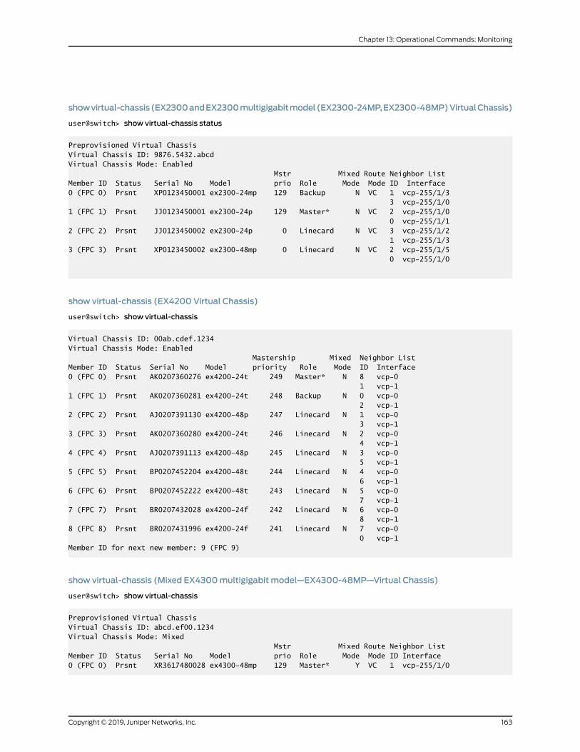
showvirtual-chassis(EX2300andEX2300multigigabitmodel(EX2300-24MP,EX2300-48MP)VirtualChassis)
user@switch> show virtual-chassis status
Preprovisioned Virtual ChassisVirtual Chassis ID: 9876.5432.abcdVirtual Chassis Mode: Enabled Mstr Mixed Route Neighbor ListMember ID Status Serial No Model prio Role Mode Mode ID Interface0 (FPC 0) Prsnt XP0123450001 ex2300-24mp 129 Backup N VC 1 vcp-255/1/3 3 vcp-255/1/01 (FPC 1) Prsnt JJ0123450001 ex2300-24p 129 Master* N VC 2 vcp-255/1/0 0 vcp-255/1/12 (FPC 2) Prsnt JJ0123450002 ex2300-24p 0 Linecard N VC 3 vcp-255/1/2 1 vcp-255/1/33 (FPC 3) Prsnt XP0123450002 ex2300-48mp 0 Linecard N VC 2 vcp-255/1/5 0 vcp-255/1/0
show virtual-chassis (EX4200 Virtual Chassis)
user@switch> show virtual-chassis
Virtual Chassis ID: 00ab.cdef.1234Virtual Chassis Mode: Enabled Mastership Mixed Neighbor ListMember ID Status Serial No Model priority Role Mode ID Interface0 (FPC 0) Prsnt AK0207360276 ex4200-24t 249 Master* N 8 vcp-0 1 vcp-1 1 (FPC 1) Prsnt AK0207360281 ex4200-24t 248 Backup N 0 vcp-0 2 vcp-1 2 (FPC 2) Prsnt AJ0207391130 ex4200-48p 247 Linecard N 1 vcp-0 3 vcp-1 3 (FPC 3) Prsnt AK0207360280 ex4200-24t 246 Linecard N 2 vcp-0 4 vcp-1 4 (FPC 4) Prsnt AJ0207391113 ex4200-48p 245 Linecard N 3 vcp-0 5 vcp-1 5 (FPC 5) Prsnt BP0207452204 ex4200-48t 244 Linecard N 4 vcp-0 6 vcp-1 6 (FPC 6) Prsnt BP0207452222 ex4200-48t 243 Linecard N 5 vcp-0 7 vcp-1 7 (FPC 7) Prsnt BR0207432028 ex4200-24f 242 Linecard N 6 vcp-0 8 vcp-1 8 (FPC 8) Prsnt BR0207431996 ex4200-24f 241 Linecard N 7 vcp-0 0 vcp-1 Member ID for next new member: 9 (FPC 9)
show virtual-chassis (Mixed EX4300multigigabit model—EX4300-48MP—Virtual Chassis)
user@switch> show virtual-chassis
Preprovisioned Virtual ChassisVirtual Chassis ID: abcd.ef00.1234Virtual Chassis Mode: Mixed Mstr Mixed Route Neighbor ListMember ID Status Serial No Model prio Role Mode Mode ID Interface0 (FPC 0) Prsnt XR3617480028 ex4300-48mp 129 Master* Y VC 1 vcp-255/1/0
163Copyright © 2019, Juniper Networks, Inc.
Chapter 13: Operational Commands: Monitoring
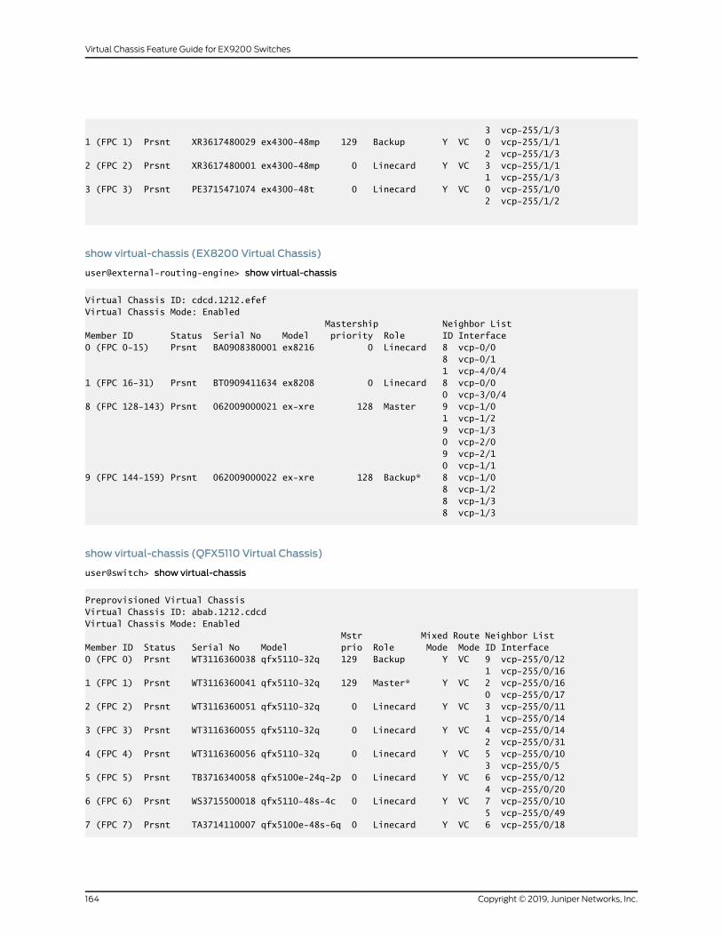
3 vcp-255/1/31 (FPC 1) Prsnt XR3617480029 ex4300-48mp 129 Backup Y VC 0 vcp-255/1/1 2 vcp-255/1/32 (FPC 2) Prsnt XR3617480001 ex4300-48mp 0 Linecard Y VC 3 vcp-255/1/1 1 vcp-255/1/3 3 (FPC 3) Prsnt PE3715471074 ex4300-48t 0 Linecard Y VC 0 vcp-255/1/0 2 vcp-255/1/2
show virtual-chassis (EX8200 Virtual Chassis)
user@external-routing-engine> show virtual-chassis
Virtual Chassis ID: cdcd.1212.efefVirtual Chassis Mode: Enabled Mastership Neighbor ListMember ID Status Serial No Model priority Role ID Interface0 (FPC 0-15) Prsnt BA0908380001 ex8216 0 Linecard 8 vcp-0/0 8 vcp-0/1 1 vcp-4/0/41 (FPC 16-31) Prsnt BT0909411634 ex8208 0 Linecard 8 vcp-0/0 0 vcp-3/0/48 (FPC 128-143) Prsnt 062009000021 ex-xre 128 Master 9 vcp-1/0 1 vcp-1/2 9 vcp-1/3 0 vcp-2/0 9 vcp-2/1 0 vcp-1/19 (FPC 144-159) Prsnt 062009000022 ex-xre 128 Backup* 8 vcp-1/0 8 vcp-1/2 8 vcp-1/3 8 vcp-1/3
show virtual-chassis (QFX5110 Virtual Chassis)
user@switch> show virtual-chassis
Preprovisioned Virtual ChassisVirtual Chassis ID: abab.1212.cdcdVirtual Chassis Mode: Enabled Mstr Mixed Route Neighbor ListMember ID Status Serial No Model prio Role Mode Mode ID Interface0 (FPC 0) Prsnt WT3116360038 qfx5110-32q 129 Backup Y VC 9 vcp-255/0/12 1 vcp-255/0/161 (FPC 1) Prsnt WT3116360041 qfx5110-32q 129 Master* Y VC 2 vcp-255/0/16 0 vcp-255/0/172 (FPC 2) Prsnt WT3116360051 qfx5110-32q 0 Linecard Y VC 3 vcp-255/0/11 1 vcp-255/0/143 (FPC 3) Prsnt WT3116360055 qfx5110-32q 0 Linecard Y VC 4 vcp-255/0/14 2 vcp-255/0/314 (FPC 4) Prsnt WT3116360056 qfx5110-32q 0 Linecard Y VC 5 vcp-255/0/10 3 vcp-255/0/55 (FPC 5) Prsnt TB3716340058 qfx5100e-24q-2p 0 Linecard Y VC 6 vcp-255/0/12 4 vcp-255/0/206 (FPC 6) Prsnt WS3715500018 qfx5110-48s-4c 0 Linecard Y VC 7 vcp-255/0/10 5 vcp-255/0/497 (FPC 7) Prsnt TA3714110007 qfx5100e-48s-6q 0 Linecard Y VC 6 vcp-255/0/18
Copyright © 2019, Juniper Networks, Inc.164
Virtual Chassis Feature Guide for EX9200 Switches
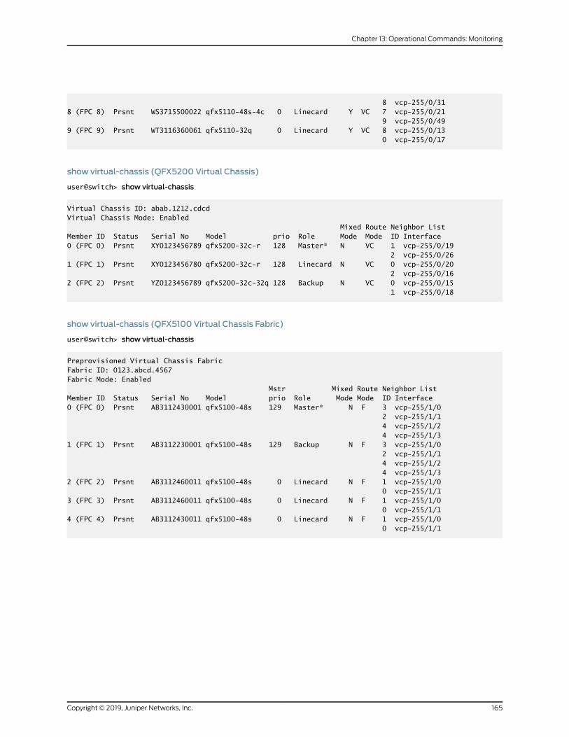
8 vcp-255/0/318 (FPC 8) Prsnt WS3715500022 qfx5110-48s-4c 0 Linecard Y VC 7 vcp-255/0/21 9 vcp-255/0/499 (FPC 9) Prsnt WT3116360061 qfx5110-32q 0 Linecard Y VC 8 vcp-255/0/13 0 vcp-255/0/17
show virtual-chassis (QFX5200 Virtual Chassis)
user@switch> show virtual-chassis
Virtual Chassis ID: abab.1212.cdcdVirtual Chassis Mode: Enabled Mixed Route Neighbor ListMember ID Status Serial No Model prio Role Mode Mode ID Interface0 (FPC 0) Prsnt XY0123456789 qfx5200-32c-r 128 Master* N VC 1 vcp-255/0/19 2 vcp-255/0/261 (FPC 1) Prsnt XY0123456780 qfx5200-32c-r 128 Linecard N VC 0 vcp-255/0/20 2 vcp-255/0/162 (FPC 2) Prsnt YZ0123456789 qfx5200-32c-32q 128 Backup N VC 0 vcp-255/0/15 1 vcp-255/0/18
show virtual-chassis (QFX5100 Virtual Chassis Fabric)
user@switch> show virtual-chassis
Preprovisioned Virtual Chassis FabricFabric ID: 0123.abcd.4567Fabric Mode: Enabled Mstr Mixed Route Neighbor ListMember ID Status Serial No Model prio Role Mode Mode ID Interface0 (FPC 0) Prsnt AB3112430001 qfx5100-48s 129 Master* N F 3 vcp-255/1/0 2 vcp-255/1/1 4 vcp-255/1/2 4 vcp-255/1/31 (FPC 1) Prsnt AB3112230001 qfx5100-48s 129 Backup N F 3 vcp-255/1/0 2 vcp-255/1/1 4 vcp-255/1/2 4 vcp-255/1/32 (FPC 2) Prsnt AB3112460011 qfx5100-48s 0 Linecard N F 1 vcp-255/1/0 0 vcp-255/1/13 (FPC 3) Prsnt AB3112460011 qfx5100-48s 0 Linecard N F 1 vcp-255/1/0 0 vcp-255/1/14 (FPC 4) Prsnt AB3112430011 qfx5100-48s 0 Linecard N F 1 vcp-255/1/0 0 vcp-255/1/1
165Copyright © 2019, Juniper Networks, Inc.
Chapter 13: Operational Commands: Monitoring
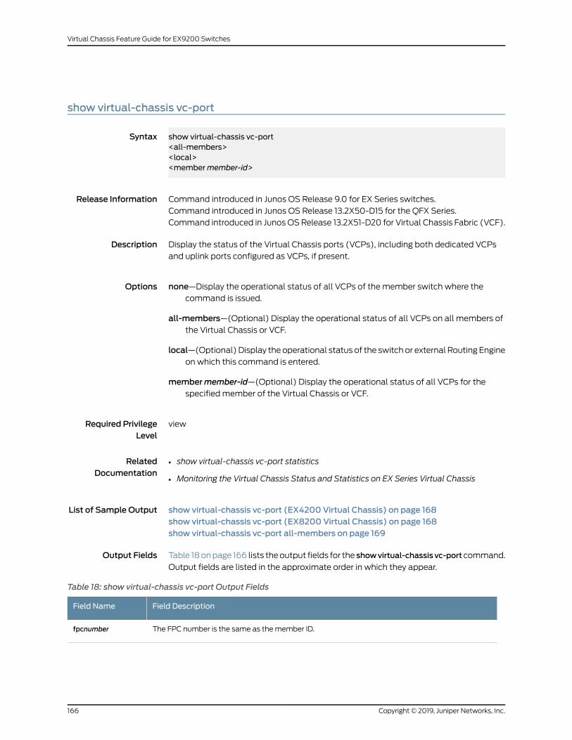
show virtual-chassis vc-port
Syntax show virtual-chassis vc-port<all-members><local><membermember-id>
Release Information Command introduced in Junos OS Release 9.0 for EX Series switches.
Command introduced in Junos OS Release 13.2X50-D15 for the QFX Series.
Command introduced in Junos OSRelease 13.2X51-D20 for Virtual Chassis Fabric (VCF).
Description Display the status of the Virtual Chassis ports (VCPs), including both dedicated VCPs
and uplink ports configured as VCPs, if present.
Options none—Display the operational status of all VCPs of the member switch where thecommand is issued.
all-members—(Optional) Display the operational status of all VCPs on all members ofthe Virtual Chassis or VCF.
local—(Optional) Display the operational status of the switch or external Routing Engineon which this command is entered.
membermember-id—(Optional) Display the operational status of all VCPs for thespecified member of the Virtual Chassis or VCF.
Required PrivilegeLevel
view
RelatedDocumentation
show virtual-chassis vc-port statistics•
• Monitoring the Virtual Chassis Status and Statistics on EX Series Virtual Chassis
List of Sample Output show virtual-chassis vc-port (EX4200 Virtual Chassis) on page 168show virtual-chassis vc-port (EX8200 Virtual Chassis) on page 168show virtual-chassis vc-port all-members on page 169
Output Fields Table 18onpage 166 lists theoutput fields for the showvirtual-chassis vc-port command.
Output fields are listed in the approximate order in which they appear.
Table 18: show virtual-chassis vc-port Output Fields
Field DescriptionField Name
The FPC number is the same as themember ID.fpcnumber
Copyright © 2019, Juniper Networks, Inc.166
Virtual Chassis Feature Guide for EX9200 Switches
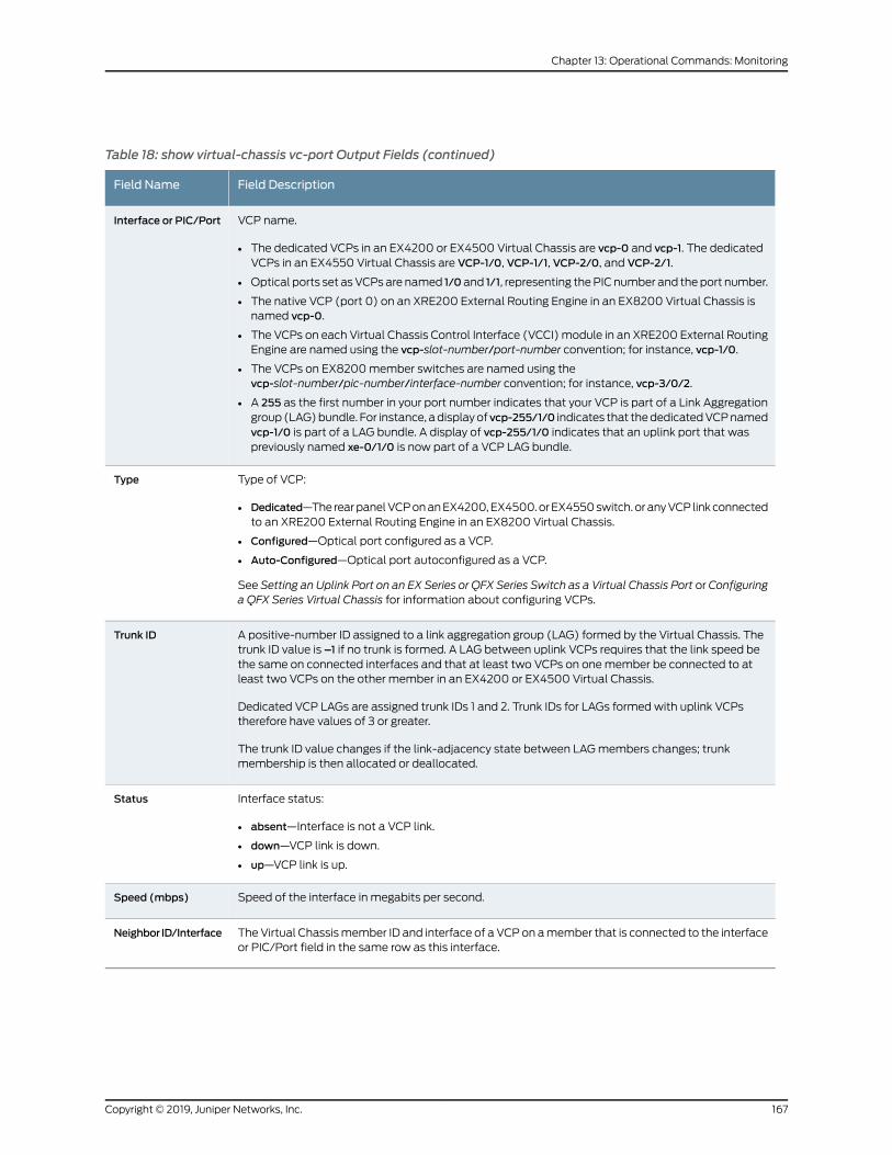
Table 18: show virtual-chassis vc-port Output Fields (continued)
Field DescriptionField Name
VCP name.
• The dedicated VCPs in an EX4200 or EX4500 Virtual Chassis are vcp-0 and vcp-1. The dedicatedVCPs in an EX4550 Virtual Chassis are VCP-1/0, VCP-1/1, VCP-2/0, and VCP-2/1.
• Optical ports set asVCPsare named 1/0and 1/1, representing thePIC number and theport number.
• The native VCP (port 0) on an XRE200 External Routing Engine in an EX8200 Virtual Chassis isnamed vcp-0.
• The VCPs on each Virtual Chassis Control Interface (VCCI) module in an XRE200 External RoutingEngine are named using the vcp-slot-number/port-number convention; for instance, vcp-1/0.
• The VCPs on EX8200member switches are named using thevcp-slot-number/pic-number/interface-number convention; for instance, vcp-3/0/2.
• A 255 as the first number in your port number indicates that your VCP is part of a Link Aggregationgroup (LAG)bundle. For instance, adisplayof vcp-255/1/0 indicates that thededicatedVCPnamedvcp-1/0 is part of a LAG bundle. A display of vcp-255/1/0 indicates that an uplink port that waspreviously named xe-0/1/0 is now part of a VCP LAG bundle.
Interface or PIC/Port
Type of VCP:
• Dedicated—The rearpanelVCPonanEX4200,EX4500.orEX4550switch.oranyVCP linkconnectedto an XRE200 External Routing Engine in an EX8200 Virtual Chassis.
• Configured—Optical port configured as a VCP.
• Auto-Configured—Optical port autoconfigured as a VCP.
See Setting an Uplink Port on an EX Series or QFX Series Switch as a Virtual Chassis Port or Configuringa QFX Series Virtual Chassis for information about configuring VCPs.
Type
A positive-number ID assigned to a link aggregation group (LAG) formed by the Virtual Chassis. Thetrunk ID value is –1 if no trunk is formed. A LAG between uplink VCPs requires that the link speed bethe same on connected interfaces and that at least two VCPs on onemember be connected to atleast two VCPs on the other member in an EX4200 or EX4500 Virtual Chassis.
Dedicated VCP LAGs are assigned trunk IDs 1 and 2. Trunk IDs for LAGs formed with uplink VCPstherefore have values of 3 or greater.
The trunk ID value changes if the link-adjacency state between LAGmembers changes; trunkmembership is then allocated or deallocated.
Trunk ID
Interface status:
• absent—Interface is not a VCP link.
• down—VCP link is down.
• up—VCP link is up.
Status
Speed of the interface in megabits per second.Speed (mbps)
TheVirtual Chassismember ID and interface of a VCPon amember that is connected to the interfaceor PIC/Port field in the same row as this interface.
Neighbor ID/Interface
167Copyright © 2019, Juniper Networks, Inc.
Chapter 13: Operational Commands: Monitoring
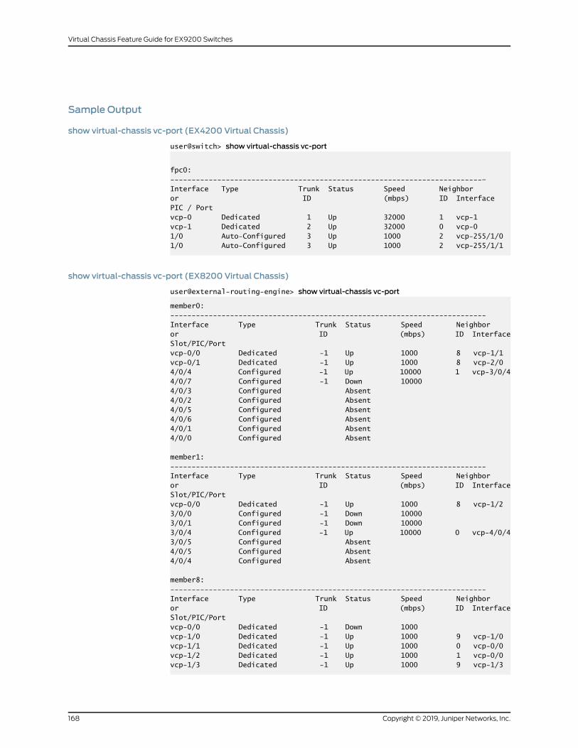
Sample Output
show virtual-chassis vc-port (EX4200 Virtual Chassis)
user@switch> show virtual-chassis vc-port
fpc0:-------------------------------------------------------------------------–Interface Type Trunk Status Speed Neighboror ID (mbps) ID InterfacePIC / Portvcp-0 Dedicated 1 Up 32000 1 vcp-1vcp-1 Dedicated 2 Up 32000 0 vcp-01/0 Auto-Configured 3 Up 1000 2 vcp-255/1/01/0 Auto-Configured 3 Up 1000 2 vcp-255/1/1
show virtual-chassis vc-port (EX8200 Virtual Chassis)
user@external-routing-engine> show virtual-chassis vc-port
member0:--------------------------------------------------------------------------Interface Type Trunk Status Speed Neighboror ID (mbps) ID InterfaceSlot/PIC/Portvcp-0/0 Dedicated -1 Up 1000 8 vcp-1/1vcp-0/1 Dedicated -1 Up 1000 8 vcp-2/04/0/4 Configured -1 Up 10000 1 vcp-3/0/44/0/7 Configured -1 Down 100004/0/3 Configured Absent4/0/2 Configured Absent4/0/5 Configured Absent4/0/6 Configured Absent4/0/1 Configured Absent4/0/0 Configured Absent
member1:--------------------------------------------------------------------------Interface Type Trunk Status Speed Neighboror ID (mbps) ID InterfaceSlot/PIC/Portvcp-0/0 Dedicated -1 Up 1000 8 vcp-1/23/0/0 Configured -1 Down 100003/0/1 Configured -1 Down 100003/0/4 Configured -1 Up 10000 0 vcp-4/0/43/0/5 Configured Absent4/0/5 Configured Absent4/0/4 Configured Absent
member8:--------------------------------------------------------------------------Interface Type Trunk Status Speed Neighboror ID (mbps) ID InterfaceSlot/PIC/Portvcp-0/0 Dedicated -1 Down 1000vcp-1/0 Dedicated -1 Up 1000 9 vcp-1/0vcp-1/1 Dedicated -1 Up 1000 0 vcp-0/0vcp-1/2 Dedicated -1 Up 1000 1 vcp-0/0vcp-1/3 Dedicated -1 Up 1000 9 vcp-1/3
Copyright © 2019, Juniper Networks, Inc.168
Virtual Chassis Feature Guide for EX9200 Switches
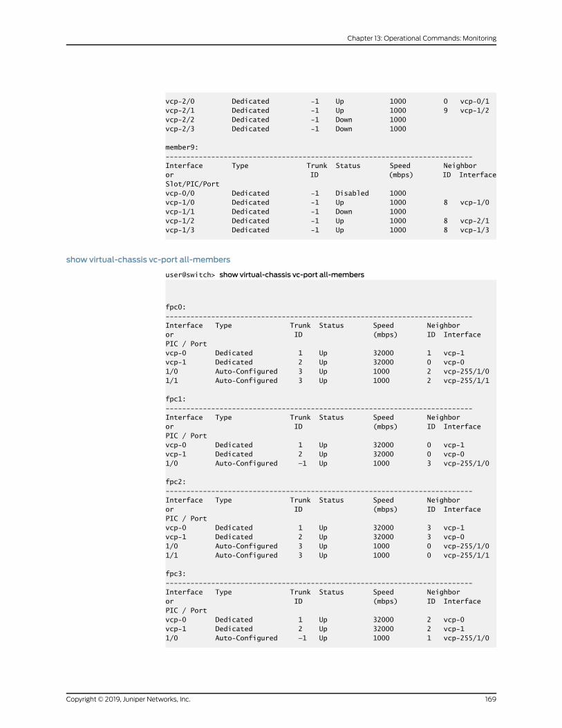
vcp-2/0 Dedicated -1 Up 1000 0 vcp-0/1vcp-2/1 Dedicated -1 Up 1000 9 vcp-1/2vcp-2/2 Dedicated -1 Down 1000vcp-2/3 Dedicated -1 Down 1000
member9:--------------------------------------------------------------------------Interface Type Trunk Status Speed Neighboror ID (mbps) ID InterfaceSlot/PIC/Portvcp-0/0 Dedicated -1 Disabled 1000vcp-1/0 Dedicated -1 Up 1000 8 vcp-1/0vcp-1/1 Dedicated -1 Down 1000vcp-1/2 Dedicated -1 Up 1000 8 vcp-2/1vcp-1/3 Dedicated -1 Up 1000 8 vcp-1/3
show virtual-chassis vc-port all-members
user@switch> show virtual-chassis vc-port all-members
fpc0:--------------------------------------------------------------------------Interface Type Trunk Status Speed Neighboror ID (mbps) ID InterfacePIC / Portvcp-0 Dedicated 1 Up 32000 1 vcp-1vcp-1 Dedicated 2 Up 32000 0 vcp-01/0 Auto-Configured 3 Up 1000 2 vcp-255/1/01/1 Auto-Configured 3 Up 1000 2 vcp-255/1/1
fpc1:--------------------------------------------------------------------------Interface Type Trunk Status Speed Neighboror ID (mbps) ID InterfacePIC / Portvcp-0 Dedicated 1 Up 32000 0 vcp-1vcp-1 Dedicated 2 Up 32000 0 vcp-01/0 Auto-Configured —1 Up 1000 3 vcp-255/1/0
fpc2:--------------------------------------------------------------------------Interface Type Trunk Status Speed Neighboror ID (mbps) ID InterfacePIC / Portvcp-0 Dedicated 1 Up 32000 3 vcp-1vcp-1 Dedicated 2 Up 32000 3 vcp-01/0 Auto-Configured 3 Up 1000 0 vcp-255/1/01/1 Auto-Configured 3 Up 1000 0 vcp-255/1/1
fpc3: --------------------------------------------------------------------------Interface Type Trunk Status Speed Neighboror ID (mbps) ID InterfacePIC / Portvcp-0 Dedicated 1 Up 32000 2 vcp-0vcp-1 Dedicated 2 Up 32000 2 vcp-1 1/0 Auto-Configured —1 Up 1000 1 vcp-255/1/0
169Copyright © 2019, Juniper Networks, Inc.
Chapter 13: Operational Commands: Monitoring

Copyright © 2019, Juniper Networks, Inc.170
Virtual Chassis Feature Guide for EX9200 Switches
Recommended

![[Chassis-shaped Switch] S7700 Switch Quick …...[Chassis-shaped Switch] S7700 Switch Quick Ordering Guide Product Overview The S7700 series switches (S7700 for short) are high-end](https://img.dokumen.tips/doc/110x75/5e9486ee7d1cd42d7b0fc167/chassis-shaped-switch-s7700-switch-quick-chassis-shaped-switch-s7700-switch.jpg)