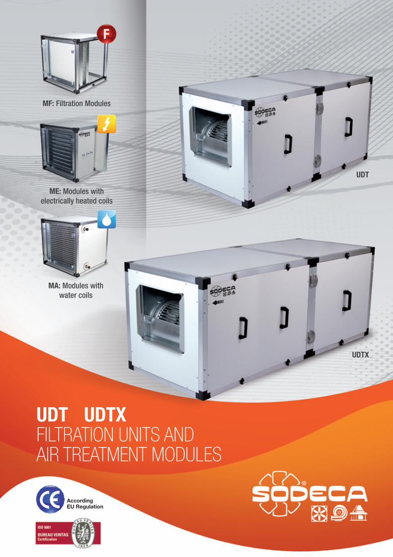
UDT UDTX FILTRATION UNITS AND AIR TREATMENT MODULES
UDT
MF: Filtration Modules
ME: Modules with electrically heated coils
MA: Modules with water coils
UDTX
According EU Regulation
UDT
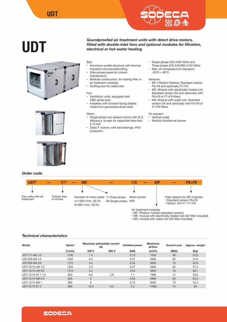
UDTBox:• Aluminiumprofilestructurewiththermal
insulationandsoundproofing.• Sideaccesspanelforcorrect
maintenance.• Modularconstruction,foraddingfilteror
airtreatmentmodules.• Stuffing-boxforcableinlet.
Fan:• Ventilationunits,equippedwith
CBDseriesfans.• Impellerswithforward-facingblades
madefromgalvanisedsheetsteel.
Motor:• Single-phasetwo-speedmotorswithIE‐2
efficiency,exceptforcapacitieslessthan0.75kW.
• ClassFmotors,withballbearings,IP54protection.
• Single-phase220‐240V50HzandThree-phase220-240/380‐415V50Hz.
• Max.airtemperaturetotransport:‐20ºC.+60ºC.
Versions:• MF:FiltrationModule.Standardversion
F6+F8andoptionallyF7+F9.• ME:Modulewithelectricallyheatedcoil.
StandardversionG4andoptionallywithF6+F8orF7+F9filters.
• MA:Modulewithwatercoil.StandardversionG4andoptionallywithF6+F8orF7+F9filters.
Onrequest:• Verticaloutlet.• Moduleinstalledasblower.
Soundproofed air treatment units with direct drive motors, fitted with double-inlet fans and optional modules for filtration, electrical or hot-water heating
Technical characteristics
Order code
UDT 7/7 4M 1/5 MF F6+F8
Fanunitswithairtreatment
Turbinesizeininches
Numberofmotorpoles4=1400r/min.50Hz6=900r/min.50Hz
Motorpower(HP)
FilteroptionsforMFmodules•StandardversionF6+F8•Option:G4+F7,F7+F9
T=Three-phaseM=Single-phase
Airtreatmentmodules•MF:filtrationmodule(standardversion)•ME:modulewithelectricallyheatedcoil(G4filterincluded)•MA:modulewithwatercoil(G4filterincluded)
Model Speed Maximum admissible current (A) Installed power Maximum
airflow Sound Level Approx. weight
(r/min) 230 V 400 V (kW) (m3/h) dB(A) (Kg)UDT-7/7-4M1/5 1230 1.4 0.15 1520 58 22.5UDT-9/9-4M1/2 1320 3.3 0.37 2800 66 31.8UDT-9/9-4M3/4 1310 4.5 0.55 3600 70 32.6UDT-10/10-4M1/2 1320 3.3 0.37 2800 65 37.3UDT-10/10-4M3/4 1310 4.5 0.55 3950 70 38.1UDT-12/12-6T11/2 850 6.6 3.8 1.1 7800 74 53.8UDT-12/12-6M3/4 850 5 0.55 4900 63 52.3UDT-12/12-6M1 850 6 0.75 6000 70 53.3UDT-15/15-6T3 890 10.9 6.3 2.2 11900 74 80
UDT
Dimensions in mm
Model A B C D1 D2 E L K
Acoustic features
Air treatment module options
Model 63 125 250 500 1000 2000 4000 8000
Sound power Lw(A) spectrum in dB(A) via frequency band in Hz
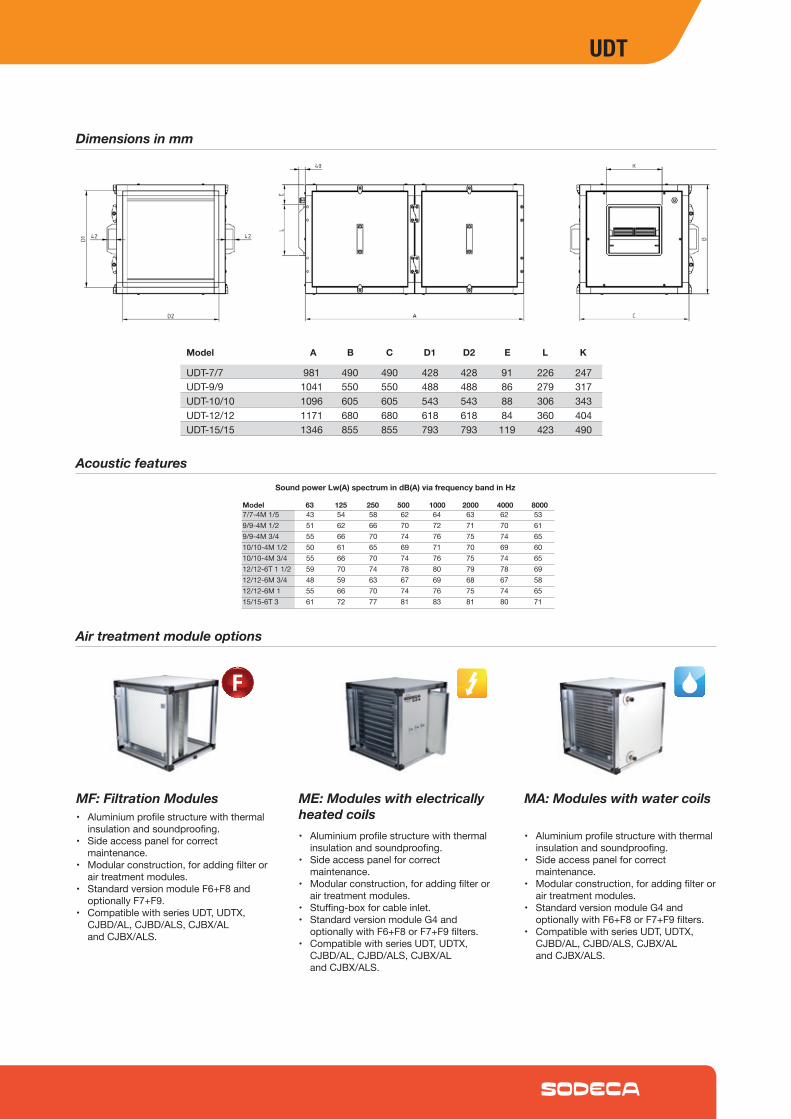
• Aluminiumprofilestructurewiththermalinsulationandsoundproofing.
• Sideaccesspanelforcorrectmaintenance.
• Modularconstruction,foraddingfilterorairtreatmentmodules.
• StandardversionmoduleF6+F8andoptionallyF7+F9.
• CompatiblewithseriesUDT,UDTX,CJBD/AL,CJBD/ALS,CJBX/ALandCJBX/ALS.
MF: Filtration Modules
• Aluminiumprofilestructurewiththermalinsulationandsoundproofing.
• Sideaccesspanelforcorrectmaintenance.
• Modularconstruction,foraddingfilterorairtreatmentmodules.
• Stuffing-boxforcableinlet.• StandardversionmoduleG4and
optionallywithF6+F8orF7+F9filters.• CompatiblewithseriesUDT,UDTX,
CJBD/AL,CJBD/ALS,CJBX/ALandCJBX/ALS.
ME: Modules with electrically heated coils
• Aluminiumprofilestructurewiththermalinsulationandsoundproofing.
• Sideaccesspanelforcorrectmaintenance.
• Modularconstruction,foraddingfilterorairtreatmentmodules.
• StandardversionmoduleG4andoptionallywithF6+F8orF7+F9filters.
• CompatiblewithseriesUDT,UDTX,CJBD/AL,CJBD/ALS,CJBX/ALandCJBX/ALS.
MA: Modules with water coils
UDT-7/7 981 490 490 428 428 91 226 247UDT-9/9 1041 550 550 488 488 86 279 317UDT-10/10 1096 605 605 543 543 88 306 343UDT-12/12 1171 680 680 618 618 84 360 404UDT-15/15 1346 855 855 793 793 119 423 490
7/7-4M1/5 43 54 58 62 64 63 62 539/9-4M1/2 51 62 66 70 72 71 70 619/9-4M3/4 55 66 70 74 76 75 74 6510/10-4M1/2 50 61 65 69 71 70 69 6010/10-4M3/4 55 66 70 74 76 75 74 6512/12-6T11/2 59 70 74 78 80 79 78 6912/12-6M3/4 48 59 63 67 69 68 67 5812/12-6M1 55 66 70 74 76 75 74 6515/15-6T3 61 72 77 81 83 81 80 71
UDT
7 7
7
7
7
9
9
9
9
910
10
10
10
1012
12
12
12
1215
15
15
15
15
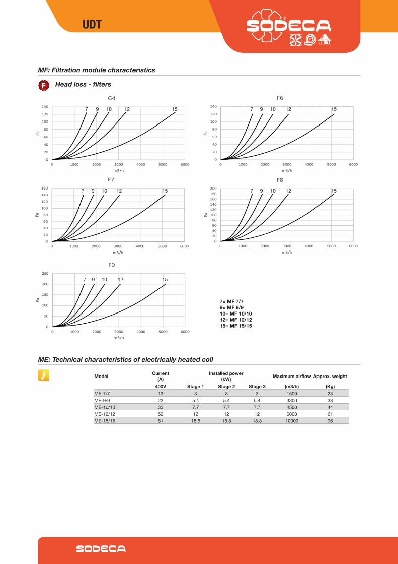
7= MF 7/79= MF 9/910= MF 10/1012= MF 12/1215= MF 15/15
MF: Filtration module characteristics
Head loss - filters
ME: Technical characteristics of electrically heated coil
Model Current(A)
Installed power(kW) Maximum airflow Approx. weight
400V Stage 1 Stage 2 Stage 3 (m3/h) (Kg)ME-7/7 13 3 3 3 1500 23ME-9/9 23 5.4 5.4 5.4 3300 33ME-10/10 33 7.7 7.7 7.7 4500 44ME-12/12 52 12 12 12 6000 61ME-15/15 81 18.8 18.8 18.8 10000 96
UDT
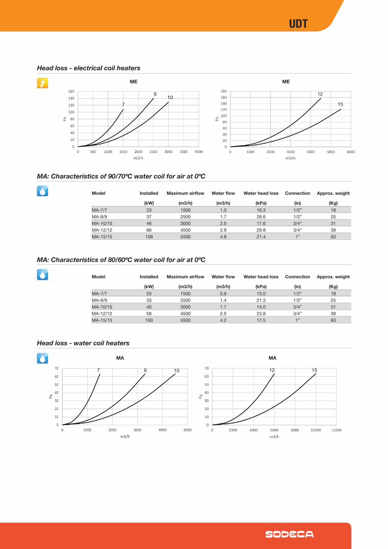
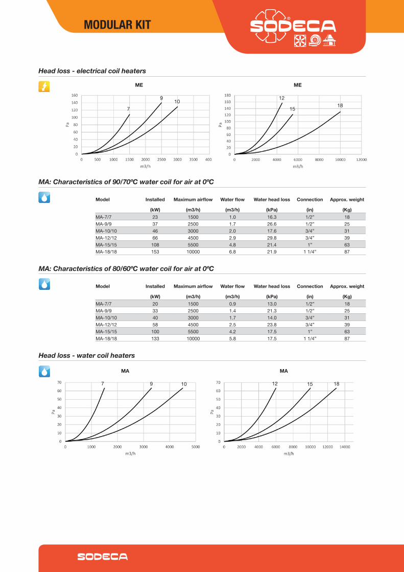
MA: Characteristics of 90/70ºC water coil for air at 0ºC
Head loss - water coil heaters
Model Installed Maximum airflow Water flow Water head loss Connection Approx. weight
(kW) (m3/h) (m3/h) (kPa) (in) (Kg)MA-7/7 23 1500 1.0 16.3 1/2” 18MA-9/9 37 2500 1.7 26.6 1/2” 25MA-10/10 46 3000 2.0 17.6 3/4” 31MA-12/12 66 4500 2.9 29.8 3/4” 39MA-15/15 108 5500 4.8 21.4 1” 63
MA: Characteristics of 80/60ºC water coil for air at 0ºC
Model Installed Maximum airflow Water flow Water head loss Connection Approx. weight
(kW) (m3/h) (m3/h) (kPa) (in) (Kg)MA-7/7 20 1500 0.9 13.0 1/2” 18MA-9/9 33 2500 1.4 21.3 1/2” 25MA-10/10 40 3000 1.7 14.0 3/4” 31MA-12/12 58 4500 2.5 23.8 3/4” 39MA-15/15 100 5500 4.2 17.5 1” 63
97 10 12 15
MA MA
Head loss - electrical coil heaters
9
710 12
15
ME ME
UDT
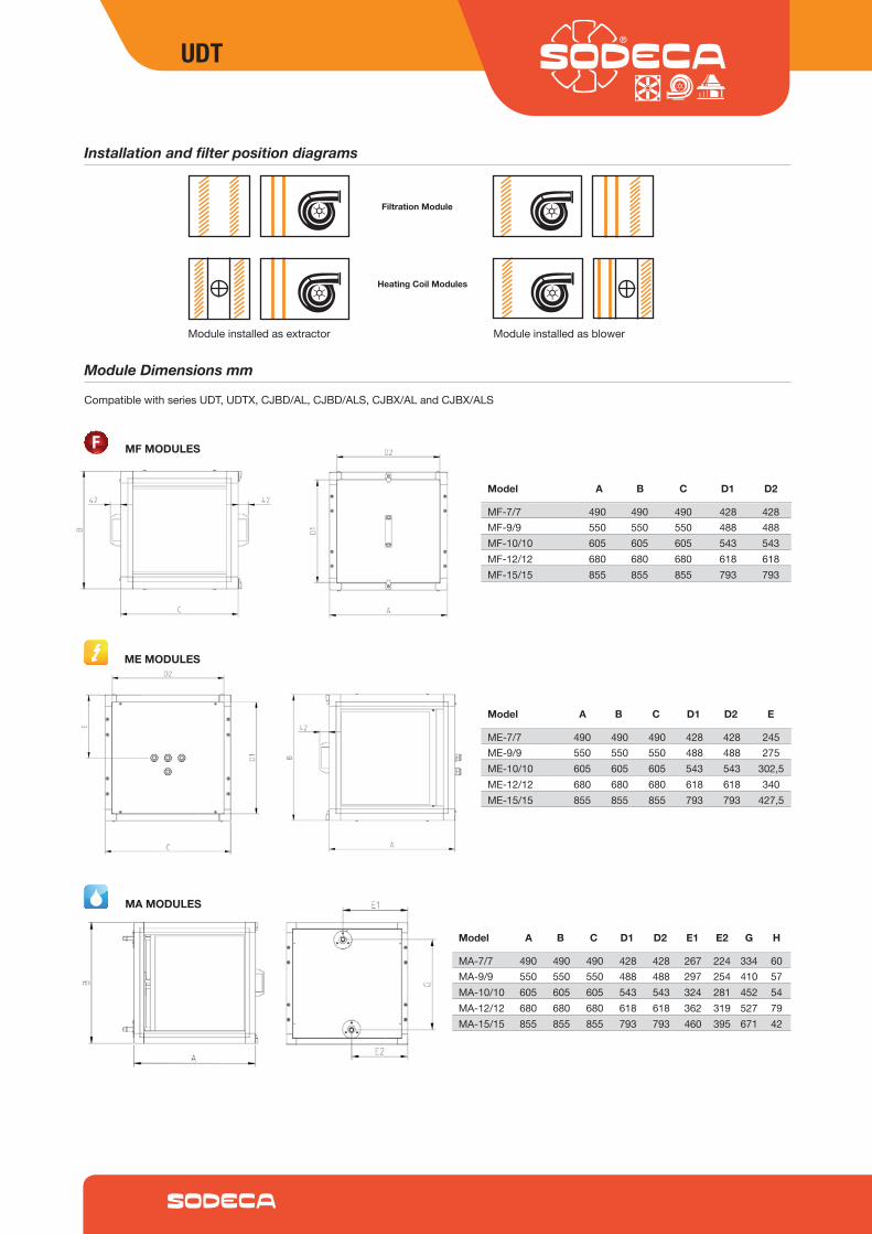
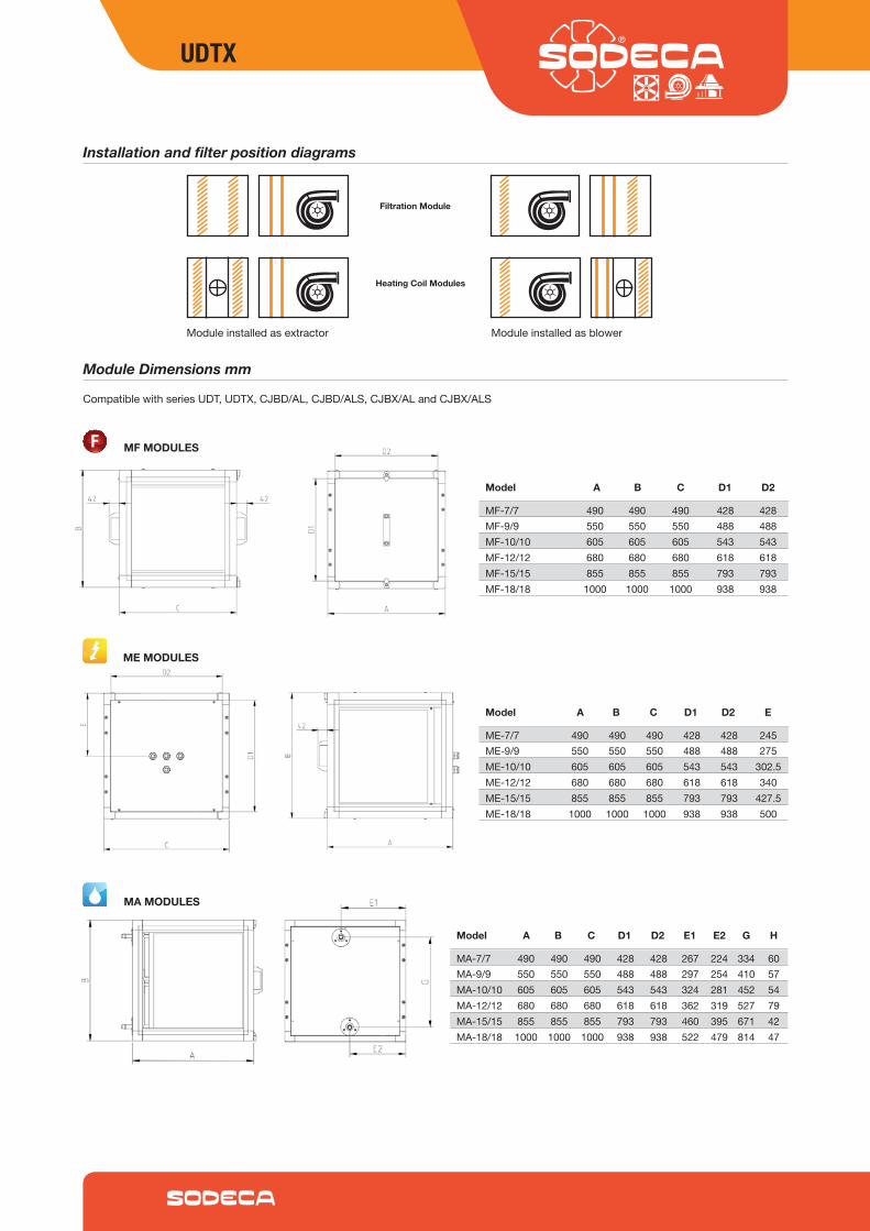
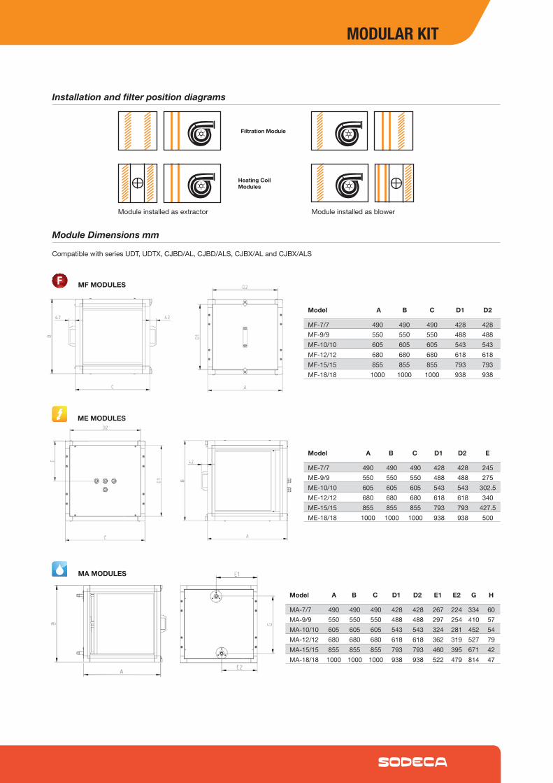
Module Dimensions mm
CompatiblewithseriesUDT,UDTX,CJBD/AL,CJBD/ALS,CJBX/ALandCJBX/ALS
MF MODULES
ME MODULES
MA MODULES
Model A B C D1 D2
Model A B C D1 D2 E
Model A B C D1 D2 E1 E2 G H
Installation and filter position diagrams
Moduleinstalledasextractor
Filtration Module
Heating Coil Modules
Moduleinstalledasblower
ME-7/7 490 490 490 428 428 245ME-9/9 550 550 550 488 488 275ME-10/10 605 605 605 543 543 302,5ME-12/12 680 680 680 618 618 340ME-15/15 855 855 855 793 793 427,5
MA-7/7 490 490 490 428 428 267 224 334 60MA-9/9 550 550 550 488 488 297 254 410 57MA-10/10 605 605 605 543 543 324 281 452 54MA-12/12 680 680 680 618 618 362 319 527 79MA-15/15 855 855 855 793 793 460 395 671 42
MF-7/7 490 490 490 428 428MF-9/9 550 550 550 488 488MF-10/10 605 605 605 543 543MF-12/12 680 680 680 618 618MF-15/15 855 855 855 793 793
UDT
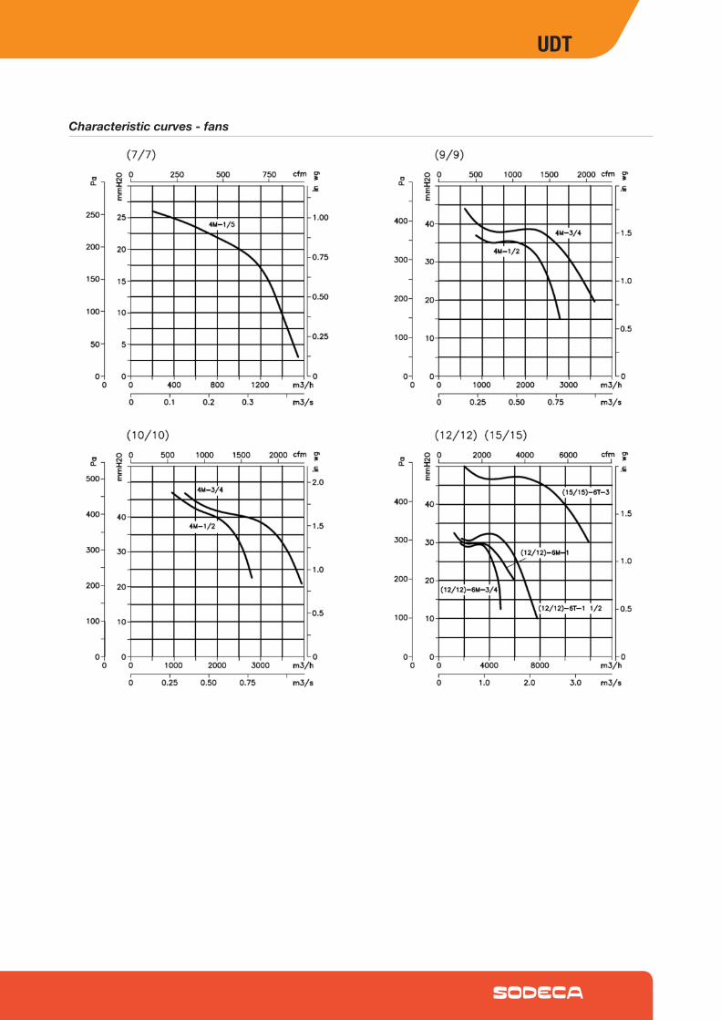
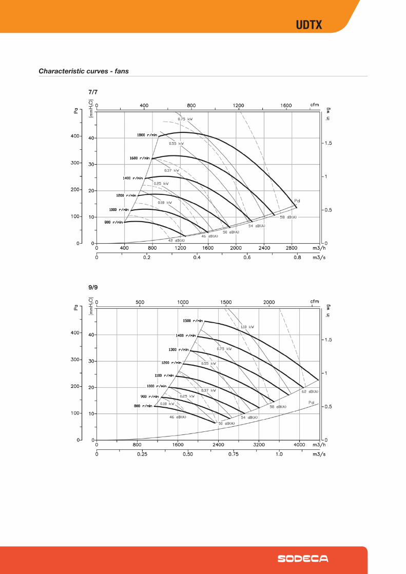
Characteristic curves - fans
UDTX
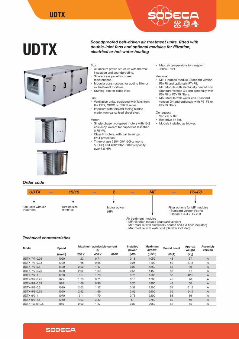
UDTXBox:• Aluminiumprofilestructurewiththermal
insulationandsoundproofing.• Sideaccesspanelforcorrect
maintenance.• Modularconstruction,foraddingfilteror
airtreatmentmodules.• Stuffing-boxforcableinlet.
Fan:• Ventilationunits,equippedwithfansfrom
theCBX,CBXCorCBXRseries• Impellerswithforward-facingblades
madefromgalvanisedsheetsteel.
Motor:• Single-phasetwo-speedmotorswithIE-2
efficiency,exceptforcapacitieslessthan0.75kW.
• ClassFmotors,withballbearings,IP54protection.
• Three-phase230/400V-50Hz.(upto5.5HP)and400/690V-50Hz(capacityover5.5HP).
• Max.airtemperaturetotransport:-20ºC+60ºC
Versions:• MF:FiltrationModule.Standardversion
F6+F8andoptionallyF7+F9.• ME:Modulewithelectricallyheatedcoil.
StandardversionG4andoptionallywithF6+F8orF7+F9filters.
• MA:Modulewithwatercoil.StandardversionG4andoptionallywithF6+F8orF7+F9filters.
Onrequest:• Verticaloutlet.• Beltdriveonleft.• Moduleinstalledasblower.
Soundproofed belt-driven air treatment units, fitted with double-inlet fans and optional modules for filtration, electrical or hot-water heating
Technical characteristics
Order code
UDTX 15/15 2 MF F6+F8
Fanunitswithairtreatment
Turbinesizeininches
Motorpower(HP)
FilteroptionsforMFmodules•StandardversionF6+F8•Option:G4+F7,F7+F9
Airtreatmentmodules•MF:filtrationmodule(standardversion)•ME:modulewithelectricallyheatedcoil(G4filterincluded)•MA:modulewithwatercoil(G4filterincluded)
Model Speed Maximum admissible current (A)
Installed power
Maximum airflow Sound Level Approx.
weightAssembly
version(r/min) 230 V 400 V 690V (kW) (m3/h) dB(A) (Kg)
UDTX-7/7-0.25 1090 1.23 0.71 0.18 1050 48 37 AUDTX-7/7-0.33 1220 1.66 0.96 0.25 1100 50 37.8 AUDTX-7/7-0.5 1420 2.02 1.17 0.37 1250 53 39 AUDTX-7/7-0.75 1600 2.92 1.69 0.55 1450 56 41 AUDTX-7/7-1 1790 3.1 1.79 0.75 1500 58 42.5 AUDTX-9/9-0.25 825 1.23 0.71 0.18 1700 45 48 AUDTX-9/9-0.33 920 1.66 0.96 0.25 1800 48 50 AUDTX-9/9-0.5 1020 2.02 1.17 0.37 2200 51 51.5 AUDTX-9/9-0.75 1050 2.92 1.69 0.55 2900 55 54.5 AUDTX-9/9-1 1070 3.1 1.79 0.75 3200 56 56 AUDTX-9/9-1.5 1260 4.03 2.32 1.1 3750 60 59 AUDTX-10/10-0.5 845 2.02 1.17 0.37 2950 52 55 A
UDTX
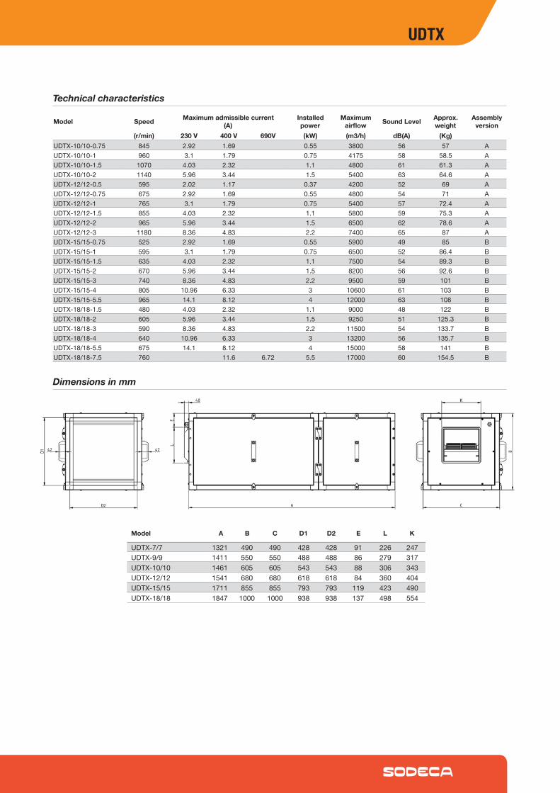
Dimensions in mm
UDTX-7/7 1321 490 490 428 428 91 226 247UDTX-9/9 1411 550 550 488 488 86 279 317UDTX-10/10 1461 605 605 543 543 88 306 343UDTX-12/12 1541 680 680 618 618 84 360 404UDTX-15/15 1711 855 855 793 793 119 423 490UDTX-18/18 1847 1000 1000 938 938 137 498 554
Model A B C D1 D2 E L K
Technical characteristics
Model Speed Maximum admissible current (A)
Installed power
Maximum airflow Sound Level Approx.
weightAssembly
version(r/min) 230 V 400 V 690V (kW) (m3/h) dB(A) (Kg)
UDTX-10/10-0.75 845 2.92 1.69 0.55 3800 56 57 AUDTX-10/10-1 960 3.1 1.79 0.75 4175 58 58.5 AUDTX-10/10-1.5 1070 4.03 2.32 1.1 4800 61 61.3 AUDTX-10/10-2 1140 5.96 3.44 1.5 5400 63 64.6 AUDTX-12/12-0.5 595 2.02 1.17 0.37 4200 52 69 AUDTX-12/12-0.75 675 2.92 1.69 0.55 4800 54 71 AUDTX-12/12-1 765 3.1 1.79 0.75 5400 57 72.4 AUDTX-12/12-1.5 855 4.03 2.32 1.1 5800 59 75.3 AUDTX-12/12-2 965 5.96 3.44 1.5 6500 62 78.6 AUDTX-12/12-3 1180 8.36 4.83 2.2 7400 65 87 AUDTX-15/15-0.75 525 2.92 1.69 0.55 5900 49 85 BUDTX-15/15-1 595 3.1 1.79 0.75 6500 52 86.4 BUDTX-15/15-1.5 635 4.03 2.32 1.1 7500 54 89.3 BUDTX-15/15-2 670 5.96 3.44 1.5 8200 56 92.6 BUDTX-15/15-3 740 8.36 4.83 2.2 9500 59 101 BUDTX-15/15-4 805 10.96 6.33 3 10600 61 103 BUDTX-15/15-5.5 965 14.1 8.12 4 12000 63 108 BUDTX-18/18-1.5 480 4.03 2.32 1.1 9000 48 122 BUDTX-18/18-2 605 5.96 3.44 1.5 9250 51 125.3 BUDTX-18/18-3 590 8.36 4.83 2.2 11500 54 133.7 BUDTX-18/18-4 640 10.96 6.33 3 13200 56 135.7 BUDTX-18/18-5.5 675 14.1 8.12 4 15000 58 141 BUDTX-18/18-7.5 760 11.6 6.72 5.5 17000 60 154.5 B
UDTX
Air treatment module options
• Aluminiumprofilestructurewiththermalinsulationandsoundproofing.
• Sideaccesspanelforcorrectmaintenance.
• Modularconstruction,foraddingfilterorairtreatmentmodules.
• StandardversionmoduleF6+F8andoptionallyF7+F9.
• CompatiblewithseriesUDT,UDTX,CJBD/AL,CJBD/ALS,CJBX/ALandCJBX/ALS.
MF: Filtration Modules
• Aluminiumprofilestructurewiththermalinsulationandsoundproofing.
• Sideaccesspanelforcorrectmaintenance.
• Modularconstruction,foraddingfilterorairtreatmentmodules.
• Stuffing-boxforcableinlet.• StandardversionmoduleG4and
optionallywithF6+F8orF7+F9filters.• CompatiblewithseriesUDT,UDTX,
CJBD/AL,CJBD/ALS,CJBX/ALandCJBX/ALS.
ME: Modules with electrically heated coils
• Aluminiumprofilestructurewiththermalinsulationandsoundproofing.
• Sideaccesspanelforcorrectmaintenance.
• Modularconstruction,foraddingfilterorairtreatmentmodules.
• StandardversionmoduleG4andoptionallywithF6+F8orF7+F9filters.
• CompatiblewithseriesUDT,UDTX,CJBD/AL,CJBD/ALS,CJBX/ALandCJBX/ALS.
MA: Modules with water coils
7 7
7
7
7
9
9
9
9
910
10
10
10
1012
12
12
12
1215
15
15
15
1518
18
18
18
18
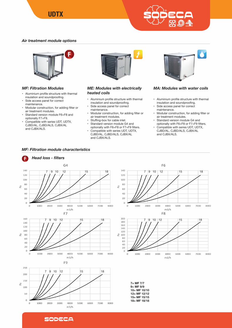
7= MF 7/79= MF 9/910= MF 10/1012= MF 12/1215= MF 15/1518= MF 18/18
MF: Filtration module characteristics
Head loss - filters
UDTX
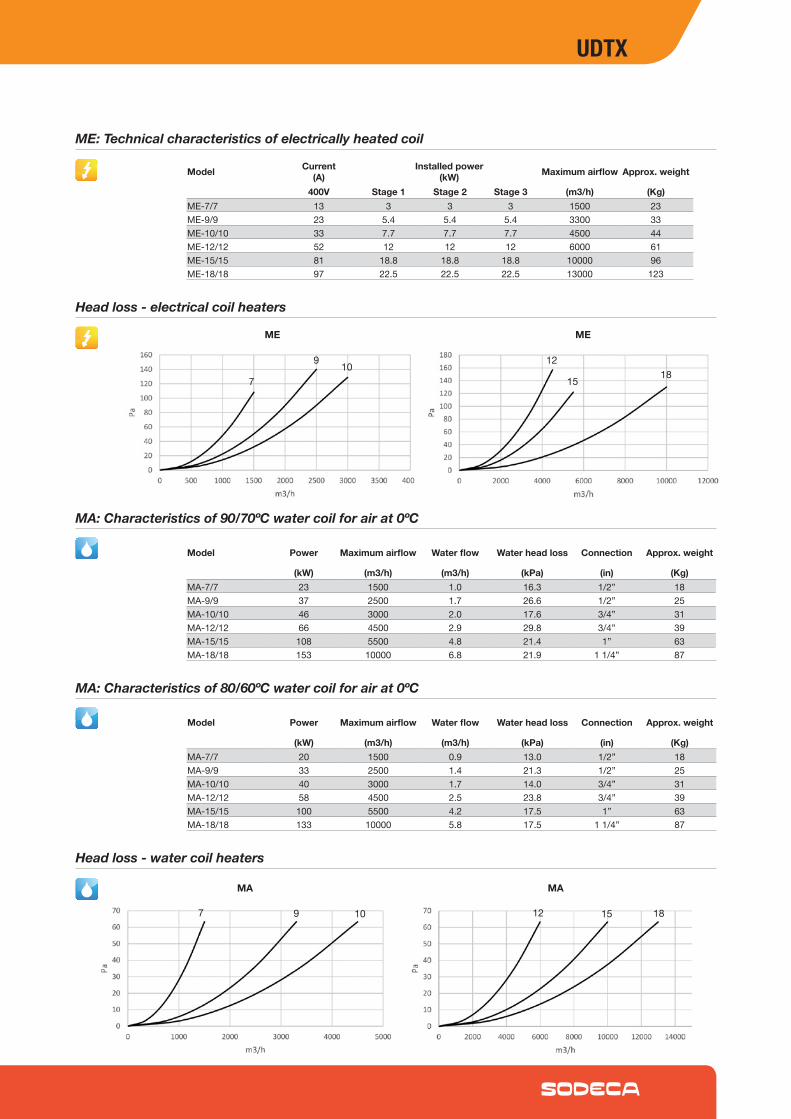
ME: Technical characteristics of electrically heated coil
Model Current(A)
Installed power(kW) Maximum airflow Approx. weight
400V Stage 1 Stage 2 Stage 3 (m3/h) (Kg)ME-7/7 13 3 3 3 1500 23ME-9/9 23 5.4 5.4 5.4 3300 33ME-10/10 33 7.7 7.7 7.7 4500 44ME-12/12 52 12 12 12 6000 61ME-15/15 81 18.8 18.8 18.8 10000 96ME-18/18 97 22.5 22.5 22.5 13000 123
MA: Characteristics of 90/70ºC water coil for air at 0ºC
Model Power Maximum airflow Water flow Water head loss Connection Approx. weight
(kW) (m3/h) (m3/h) (kPa) (in) (Kg)MA-7/7 23 1500 1.0 16.3 1/2” 18MA-9/9 37 2500 1.7 26.6 1/2” 25MA-10/10 46 3000 2.0 17.6 3/4” 31MA-12/12 66 4500 2.9 29.8 3/4” 39MA-15/15 108 5500 4.8 21.4 1” 63MA-18/18 153 10000 6.8 21.9 11/4” 87
Head loss - electrical coil heaters
9
710 12
15 18
ME ME
MA: Characteristics of 80/60ºC water coil for air at 0ºC
Model Power Maximum airflow Water flow Water head loss Connection Approx. weight
(kW) (m3/h) (m3/h) (kPa) (in) (Kg)MA-7/7 20 1500 0.9 13.0 1/2” 18MA-9/9 33 2500 1.4 21.3 1/2” 25MA-10/10 40 3000 1.7 14.0 3/4” 31MA-12/12 58 4500 2.5 23.8 3/4” 39MA-15/15 100 5500 4.2 17.5 1” 63MA-18/18 133 10000 5.8 17.5 11/4” 87
Head loss - water coil heaters
97 10 12 15 18
MA MA
UDTX
Module Dimensions mm
CompatiblewithseriesUDT,UDTX,CJBD/AL,CJBD/ALS,CJBX/ALandCJBX/ALS
MF MODULES
ME MODULES
MA MODULES
Model A B C D1 D2
Model A B C D1 D2 E
Model A B C D1 D2 E1 E2 G H
Installation and filter position diagrams
Moduleinstalledasextractor
Filtration Module
Heating Coil Modules
Moduleinstalledasblower
MF-7/7 490 490 490 428 428MF-9/9 550 550 550 488 488MF-10/10 605 605 605 543 543MF-12/12 680 680 680 618 618MF-15/15 855 855 855 793 793MF-18/18 1000 1000 1000 938 938
ME-7/7 490 490 490 428 428 245ME-9/9 550 550 550 488 488 275ME-10/10 605 605 605 543 543 302.5ME-12/12 680 680 680 618 618 340ME-15/15 855 855 855 793 793 427.5ME-18/18 1000 1000 1000 938 938 500
MA-7/7 490 490 490 428 428 267 224 334 60MA-9/9 550 550 550 488 488 297 254 410 57MA-10/10 605 605 605 543 543 324 281 452 54MA-12/12 680 680 680 618 618 362 319 527 79MA-15/15 855 855 855 793 793 460 395 671 42MA-18/18 1000 1000 1000 938 938 522 479 814 47
UDTX
Characteristic curves - fans
9/9
7/7
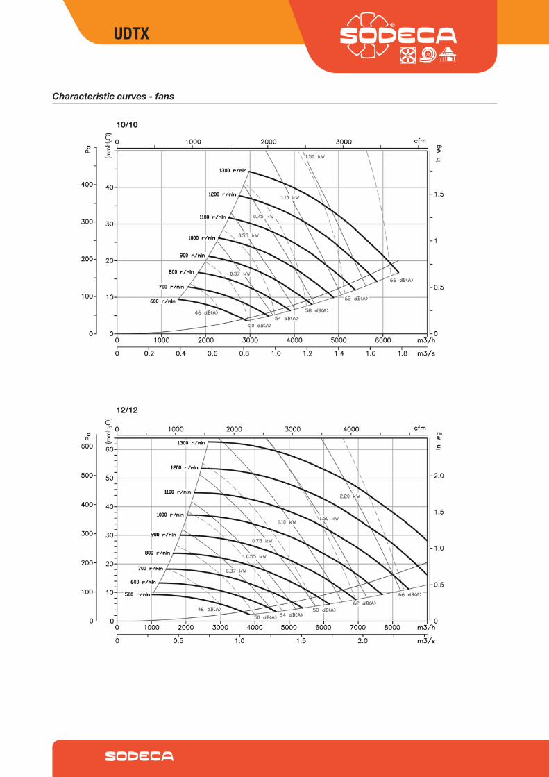
UDTX
Characteristic curves - fans
12/12
10/10
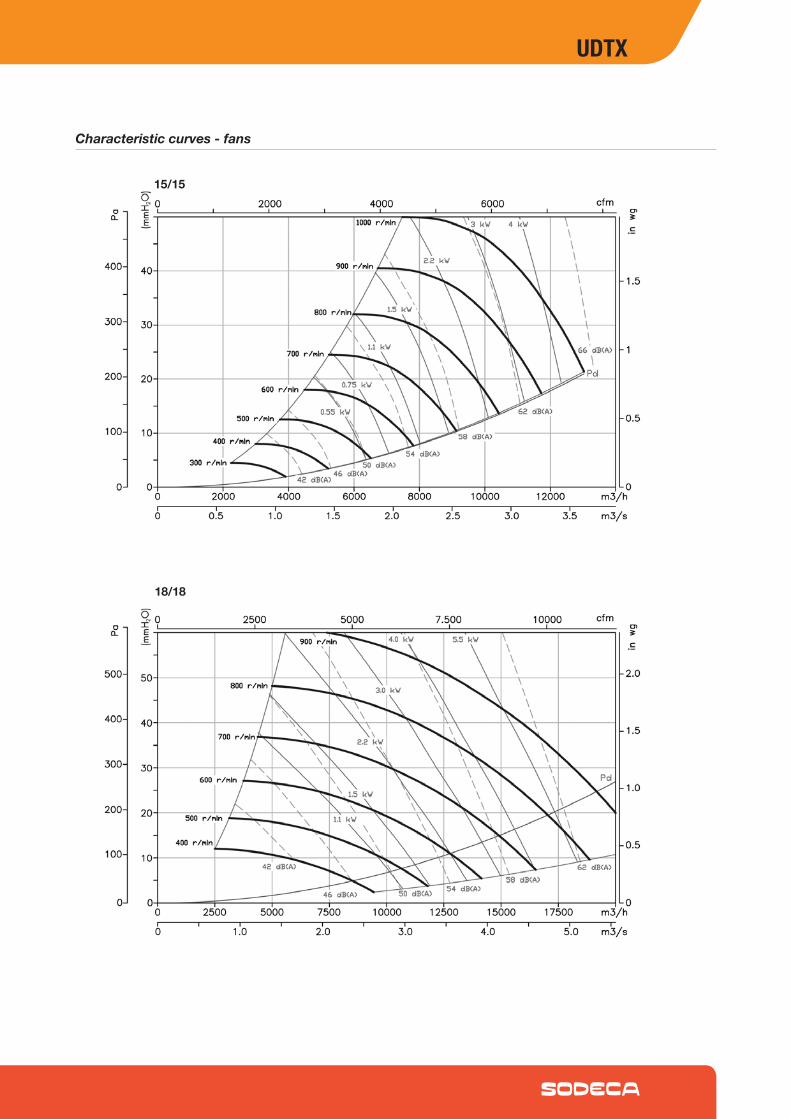
UDTX
Characteristic curves - fans
15/15
18/18
MODULAR KIT
MODULAR KIT AIR TREATMENT UNITS
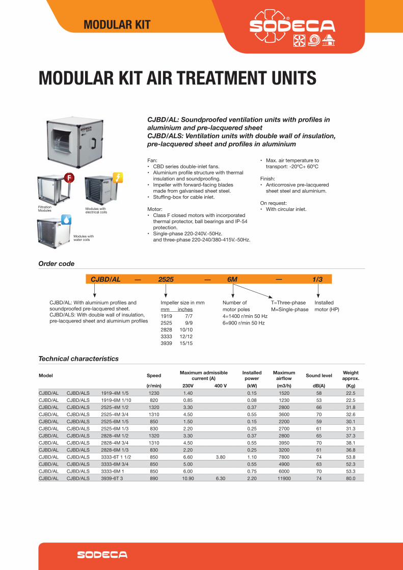
CJBD/AL: Soundproofed ventilation units with profiles in aluminium and pre-lacquered sheetCJBD/ALS: Ventilation units with double wall of insulation, pre-lacquered sheet and profiles in aluminium
Fan:• CBDseriesdouble-inletfans.• Aluminiumprofilestructurewiththermal
insulationandsoundproofing.• Impellerwithforward-facingblades
madefromgalvanisedsheetsteel.• Stuffing-boxforcableinlet.
Motor:• ClassFclosedmotorswithincorporated
thermalprotector,ballbearingsandIP-54protection.
• Single-phase220-240V.-50Hz.andthree-phase220-240/380-415V.-50Hz.
• Max.airtemperaturetotransport:-20ºC+60ºC
Finish:• Anticorrosivepre-lacquered
sheetsteelandaluminium.
Onrequest:• Withcircularinlet.
Order code
CJBD/AL 2525 6M 1/3
Impellersizeinmmmm inches1919 7/72525 9/92828 10/103333 12/123939 15/15
CJBD/AL:Withaluminiumprofilesandsoundproofedpre-lacqueredsheet.CJBD/ALS:Withdoublewallofinsulation,pre-lacqueredsheetandaluminiumprofiles
Numberofmotorpoles4=1400r/min50Hz6=900r/min50Hz
Installedmotor(HP)
T=Three-phaseM=Single-phase
Model Speed Maximum admissible current (A)
Installed power
Maximum airflow Sound level Weight
approx.(r/min) 230V 400 V (kW) (m3/h) dB(A) (Kg)
CJBD/AL CJBD/ALS 1919-4M1/5 1230 1.40 0.15 1520 58 22.5CJBD/AL CJBD/ALS 1919-6M1/10 820 0.85 0.08 1230 53 22.5CJBD/AL CJBD/ALS 2525-4M1/2 1320 3.30 0.37 2800 66 31.8CJBD/AL CJBD/ALS 2525-4M3/4 1310 4.50 0.55 3600 70 32.6CJBD/AL CJBD/ALS 2525-6M1/5 850 1.50 0.15 2200 59 30.1CJBD/AL CJBD/ALS 2525-6M1/3 830 2.20 0.25 2700 61 31.3CJBD/AL CJBD/ALS 2828-4M1/2 1320 3.30 0.37 2800 65 37.3CJBD/AL CJBD/ALS 2828-4M3/4 1310 4.50 0.55 3950 70 38.1CJBD/AL CJBD/ALS 2828-6M1/3 830 2.20 0.25 3200 61 36.8CJBD/AL CJBD/ALS 3333-6T11/2 850 6.60 3.80 1.10 7800 74 53.8CJBD/AL CJBD/ALS 3333-6M3/4 850 5.00 0.55 4900 63 52.3CJBD/AL CJBD/ALS 3333-6M1 850 6.00 0.75 6000 70 53.3CJBD/AL CJBD/ALS 3939-6T3 890 10.90 6.30 2.20 11900 74 80.0
Technical characteristics
Moduleswithelectricalcoils
Moduleswithwatercoils
FiltrationModules
MODULAR KIT
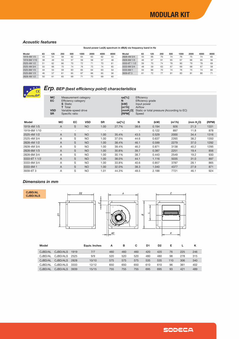
Erp. BEP (best efficiency point) characteristics
MCModel1919-4M1/5 A S NO 1.00 27.7% 38.6 0.194 926 21.3 13311919-6M1/10 - - - - - - 0.122 897 11.8 8782525-4M1/2 A S NO 1.00 35.4% 43.5 0.529 2000 34.4 13162525-4M3/4 A S NO 1.00 37.0% 44.6 0.637 2265 38.2 13502828-4M1/2 A S NO 1.00 38.4% 46.1 0.599 2279 37.0 12922828-4M3/4 A S NO 1.00 39.4% 46.2 0.871 3138 40.2 12952828-6M1/3 A S NO 1.00 30.8% 39.7 0.387 2251 19.4 8562828-6M3/4 A S NO 1.00 30.1% 38.7 0.443 2549 19.2 9303333-6T11/2 A S NO 1.00 38.0% 44.1 1.116 5035 31.0 8973333-6M3/4 A S NO 1.00 33.8% 40.6 0.857 3787 28.1 8653333-6M1 A S NO 1.00 32.0% 38.3 1.040 4377 27.9 8713939-6T3 A S NO 1.01 44.3% 48.5 2.188 7721 46.1 924
EC VSD SR ηe[%] N (kW) (m3/h) (mm H2O)
MC MeasurementcategoryEC Efficiencycategory S Static T TotalVSD Variable-speeddriveSR Specificratio
ηe[%] EfficiencyN Efficiencygrade[kW] Inputpower[m3/h] Airflow[mmH2O] Staticortotalpressure(AccordingtoEC)[RPM] Speed
Dimensions in mm
CJBD/ALCJBD/ALS
CJBD/ALCJBD/ALS1919 7/7 460 460 460 420 420 76 225 246CJBD/ALCJBD/ALS2525 9/9 520 520 520 480 480 98 278 315CJBD/ALCJBD/ALS2828 10/10 575 575 575 535 535 110 306 340CJBD/ALCJBD/ALS3333 12/12 650 650 650 610 610 96 361 402CJBD/ALCJBD/ALS3939 15/15 755 755 755 695 695 93 421 489
Model Equiv. Inches A B C D1 D2 E L K
Acoustic featuresSound power Lw(A) spectrum in dB(A) via frequency band in Hz
Model 63 125 250 500 1000 2000 4000 8000 Model 63 125 250 500 1000 2000 4000 80001919-4M1/5 43 54 58 62 64 63 62 531919-6M1/10 38 49 53 57 59 58 57 482525-4M1/2 51 62 66 70 72 71 70 612525-4M3/4 55 66 70 74 76 75 74 652525-6M1/5 44 55 59 63 65 64 63 542525-6M1/3 46 57 61 65 67 66 65 562828-4M1/2 50 61 65 69 71 70 69 60
2828-4M3/4 55 66 70 74 76 75 74 652828-6M1/3 46 57 61 65 67 66 65 563333-6T11/2 59 70 74 78 80 79 78 693333-6M3/4 48 59 63 67 69 68 67 583333-6M1 55 66 70 74 76 75 74 653939-6T3 61 72 77 81 83 81 80 71
(RPM)
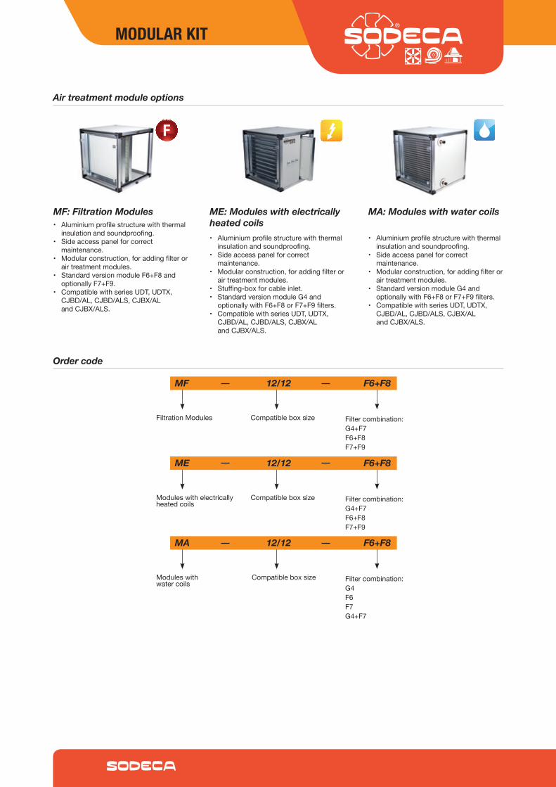
Order code
MF 12/12 F6+F8
ME 12/12 F6+F8
MA 12/12 F6+F8
FiltrationModules
Moduleswithelectricallyheatedcoils
Moduleswithwatercoils
Compatibleboxsize
Compatibleboxsize
Compatibleboxsize
Filtercombination:G4+F7F6+F8F7+F9
Filtercombination:G4+F7F6+F8F7+F9
Filtercombination:G4F6F7G4+F7
Air treatment module options
• Aluminiumprofilestructurewiththermalinsulationandsoundproofing.
• Sideaccesspanelforcorrectmaintenance.
• Modularconstruction,foraddingfilterorairtreatmentmodules.
• StandardversionmoduleF6+F8andoptionallyF7+F9.
• CompatiblewithseriesUDT,UDTX,CJBD/AL,CJBD/ALS,CJBX/ALandCJBX/ALS.
MF: Filtration Modules
• Aluminiumprofilestructurewiththermalinsulationandsoundproofing.
• Sideaccesspanelforcorrectmaintenance.
• Modularconstruction,foraddingfilterorairtreatmentmodules.
• Stuffing-boxforcableinlet.• StandardversionmoduleG4and
optionallywithF6+F8orF7+F9filters.• CompatiblewithseriesUDT,UDTX,
CJBD/AL,CJBD/ALS,CJBX/ALandCJBX/ALS.
ME: Modules with electrically heated coils
• Aluminiumprofilestructurewiththermalinsulationandsoundproofing.
• Sideaccesspanelforcorrectmaintenance.
• Modularconstruction,foraddingfilterorairtreatmentmodules.
• StandardversionmoduleG4andoptionallywithF6+F8orF7+F9filters.
• CompatiblewithseriesUDT,UDTX,CJBD/AL,CJBD/ALS,CJBX/ALandCJBX/ALS.
MA: Modules with water coils
MODULAR KIT
7 7
7
7
7
9
9
9
9
910
10
10
10
1012
12
12
12
1215
15
15
15
1518
18
18
18
18
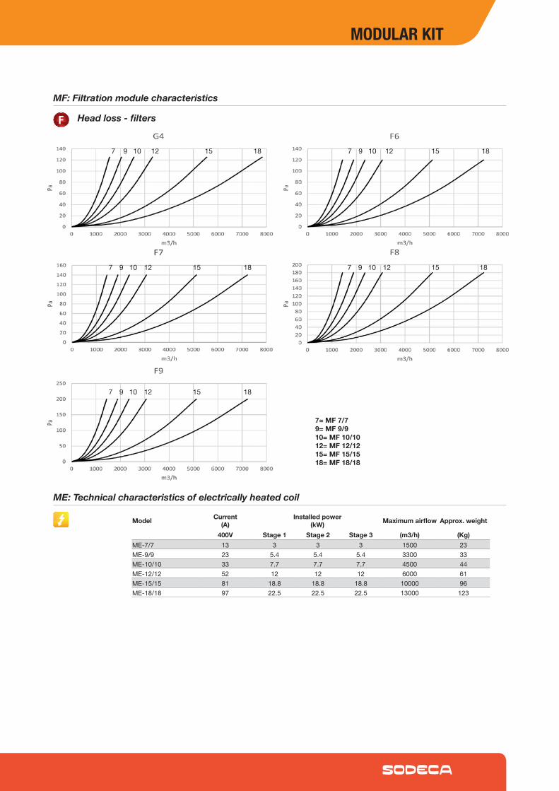
7= MF 7/79= MF 9/910= MF 10/1012= MF 12/1215= MF 15/1518= MF 18/18
MF: Filtration module characteristics
Head loss - filters
ME: Technical characteristics of electrically heated coil
Model Current(A)
Installed power(kW) Maximum airflow Approx. weight
400V Stage 1 Stage 2 Stage 3 (m3/h) (Kg)ME-7/7 13 3 3 3 1500 23ME-9/9 23 5.4 5.4 5.4 3300 33ME-10/10 33 7.7 7.7 7.7 4500 44ME-12/12 52 12 12 12 6000 61ME-15/15 81 18.8 18.8 18.8 10000 96ME-18/18 97 22.5 22.5 22.5 13000 123
MODULAR KIT
MA: Characteristics of 90/70ºC water coil for air at 0ºC
Model Installed Maximum airflow Water flow Water head loss Connection Approx. weight
(kW) (m3/h) (m3/h) (kPa) (in) (Kg)MA-7/7 23 1500 1.0 16.3 1/2” 18MA-9/9 37 2500 1.7 26.6 1/2” 25MA-10/10 46 3000 2.0 17.6 3/4” 31MA-12/12 66 4500 2.9 29.8 3/4” 39MA-15/15 108 5500 4.8 21.4 1” 63MA-18/18 153 10000 6.8 21.9 11/4” 87
MA: Characteristics of 80/60ºC water coil for air at 0ºC
Model Installed Maximum airflow Water flow Water head loss Connection Approx. weight
(kW) (m3/h) (m3/h) (kPa) (in) (Kg)MA-7/7 20 1500 0.9 13.0 1/2” 18MA-9/9 33 2500 1.4 21.3 1/2” 25MA-10/10 40 3000 1.7 14.0 3/4” 31MA-12/12 58 4500 2.5 23.8 3/4” 39MA-15/15 100 5500 4.2 17.5 1” 63MA-18/18 133 10000 5.8 17.5 11/4” 87
Head loss - water coil heaters
97 10 12 15 18
MA MA
Head loss - electrical coil heaters
9
710 12
15 18
ME ME
MODULAR KIT
Module Dimensions mm
CompatiblewithseriesUDT,UDTX,CJBD/AL,CJBD/ALS,CJBX/ALandCJBX/ALS
MF MODULES
ME MODULES
MA MODULES
MF-7/7 490 490 490 428 428MF-9/9 550 550 550 488 488MF-10/10 605 605 605 543 543MF-12/12 680 680 680 618 618MF-15/15 855 855 855 793 793MF-18/18 1000 1000 1000 938 938
ME-7/7 490 490 490 428 428 245ME-9/9 550 550 550 488 488 275ME-10/10 605 605 605 543 543 302.5ME-12/12 680 680 680 618 618 340ME-15/15 855 855 855 793 793 427.5ME-18/18 1000 1000 1000 938 938 500
MA-7/7 490 490 490 428 428 267 224 334 60MA-9/9 550 550 550 488 488 297 254 410 57MA-10/10 605 605 605 543 543 324 281 452 54MA-12/12 680 680 680 618 618 362 319 527 79MA-15/15 855 855 855 793 793 460 395 671 42MA-18/18 1000 1000 1000 938 938 522 479 814 47
Model A B C D1 D2
Model A B C D1 D2 E
Model A B C D1 D2 E1 E2 G H
Installation and filter position diagrams
Moduleinstalledasextractor
Filtration Module
Heating Coil Modules
Moduleinstalledasblower
MODULAR KIT
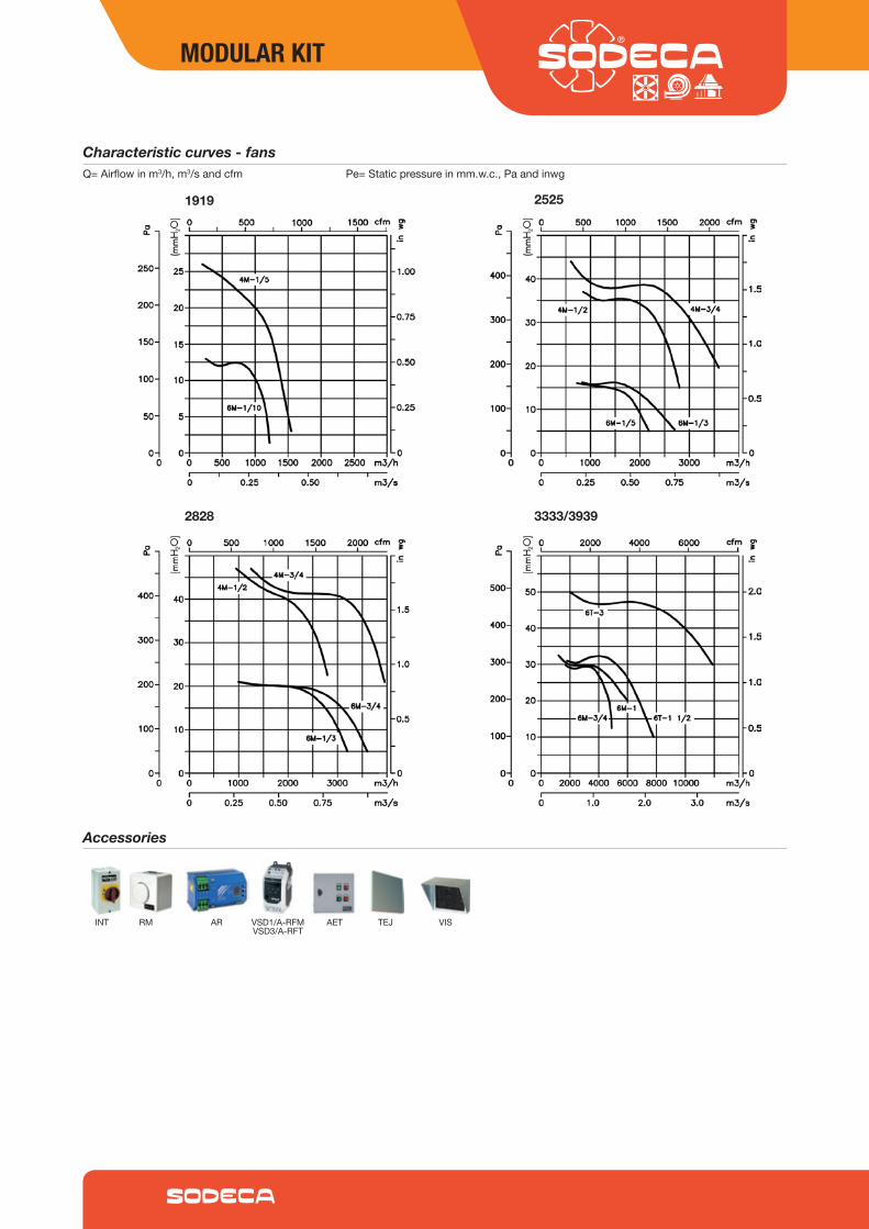
Characteristic curves - fans Q=Airflowinm3/h,m3/sandcfm Pe=Staticpressureinmm.w.c.,Paandinwg
1919 2525
2828 3333/3939
Accessories
TEJ VISINT AR VSD1/A-RFMVSD3/A-RFT
AETRM
MODULAR KIT

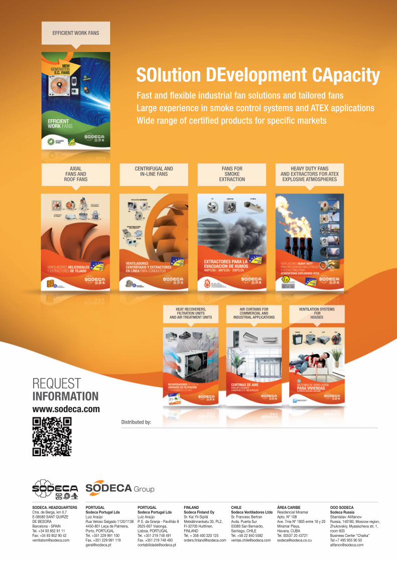
Fast and flexible industrial fan solutions and tailored fansLarge experience in smoke control systems and ATEX applicationsWide range of certified products for specific markets
HEAT RECOVERERS, FILTRATION UNITS
AND AIR TREATMENT UNITS
VENTILATION SYSTEMS FOR
HOUSES
AXIAL FANS AND
ROOF FANS
CENTRIFUGAL AND IN-LINE FANS
HEAVY DUTY FANSAND EXTRACTORS FOR ATEX EXPLOSIVE ATMOSPHERES
AIR CURTAINS FOR COMMERCIAL AND
INDUSTRIAL APPLICATIONS
FANS FOR SMOKE
EXTRACTION
EFFICIENT WORK FANS
REQUESTINFORMATIONwww.sodeca.com
Distributed by:
PORTUGAL Sodeca Portugal LdaLuizAraújoRuaVelosoSalgado1120/11384450-801LeçadePalmeira,Porto,[email protected]
FINLANDSodeca Finland OySr.KaiYli-SipiläMetsälinnankatu30,PL2,FI-32700Huittinen,[email protected]
CHILESodeca Ventiladores LtdaSr.FrancescBertranAvda.PuertaSur03380SanBernardo,Santiago,[email protected]
ÁREA CARIBEResidencialMiramarApto.Nº108Ave.7maNº1805entre18y20MiramarPlaya,Havana,[email protected]
SODECA. HEADQUARTERSCtra.deBerga,km0,7E-08580SANTQUIRZEDEBESORABarcelona-SPAINTel.+34938529111Fax:[email protected]
PORTUGAL Sodeca Portugal LdaLuizAraújoP.E.daGranja-Pavilhão82625-607Vialonga,Lisboa,PORTUGALTel.+351219748491Fax.+351219748493contabilidade@sodeca.pt
OOO SODECASodeca RussiaStanislavAlifanovRussia,140180,Moscowregion,Zhukovskiy,Myasischevastr,1,room603BusinessСenter“Chaika”Tel:[email protected]
Recommended