Tutorial
Creating 3DAnimations
in
TNTmips®
TNTedit™
TNTview®
3D
ANI
MATION
page 2
Creating 3D Animations
Before Getting Started
It may be difficult to identify the important points in some illustrations withouta color copy of this booklet. You can print or read this booklet in color fromMicroImages’ Web site. The Web site is also your source for the newesttutorial booklets on other topics. You can download an installation guide,sample data, and the latest version of TNTlite:
http://www.microimages.com
This booklet introduces techniques for constructing and manipulating animated3D perspectives in TNTmips®, TNTedit™, and TNTview®. Animated 3D perspec-tives are constructed from a surface object, one or more drape objects, and aselected path through the terrain. After you define the 3D animation, you canview a wireframe preview, render the solid surface animation in the view window(only a very fast computer will give satisfactory solid renderings in real time), orcreate an MPEG file for later viewing and wider distribution.
Prerequisite Skills This booklet is a companion volume to the tutorial 3D Per-spective Visualization. Take up the exercises in this booklet only after you arefamiliar with the concepts in that booklet. This booklet also assumes that youhave completed the exercises in the tutorials Displaying Geospatial Data andNavigation. The exercises in those booklets present basic skills and techniquesthat are not covered again here. Please consult those booklets for any review youneed.
Sample Data The exercises presented in this booklet use sample data that isdistributed with the TNT products. If you do not have access to a TNT prod-ucts CD, you can download the data from MicroImages’ Web site. In particu-lar, this booklet uses objects in the CB_DATA data collection. Make a read-writecopy of these files on your hard drive; you may encounter problems if youwork directly with the read-only sample data on the CD-ROM.
More Documentation This booklet is intended only as an introduction to 3Danimation. Consult the TNT Reference Manual for more information.
TNTmips and TNTlite® TNTmips comes in two versions: the professional ver-sion and the free TNTlite version. This booklet refers to both versions as“TNTmips.” If you did not purchase the professional version (which requires asoftware license key), TNTmips operates in TNTlite mode, which limits objectsize.
The 3D Perspective process is available in TNTmips, TNTedit, and TNTview. Allthe exercises can be completed in TNTlite using the sample geodata
Keith Ghormley, 25 April 2005
page 3
Creating 3D Animations
Making 3D AnimationsThe Display Spatial Data process in the TNT prod-ucts provides a number of flexible tools for 3Dand stereo 3D visualization of many kinds of projectmaterials. One of the most powerful visualizationfeatures is 3D animation, which lets you create ananimated fly-by of any 3D surface. You can fly overelevation surfaces (or sail over bathymetric surfaces)for realistic animations, or you can use non-physi-cal surfaces: any kind of raster object generated byTNT’s analytical processes that lends itself to 3Dvisualization. Your animation can follow a linear pathor a complex line, it can orbit a central point, or it canremain at a fixed point and pan the view.
You can define complex overlays that include raster,CAD, vector, TIN, and database pinmap layers.
The general sequence of steps is:
1. select a surface object and first drape layer2. define a flight path3. add drape layers4. record the result
Steps 2 and 3 can be mixed,but generally it is quicker todefine the flight path on asingle drape layer whileworking with the surfaceobject in 3D wireframe pre-view. Even moderately pow-ered computers can rendera 3D wireframe animation inreal time, while only very fastcomputers can give satis-factory results rendering a3D animation in solid view.To view a solid 3D anima-tion, it is more practical tocreate an output animationfile.
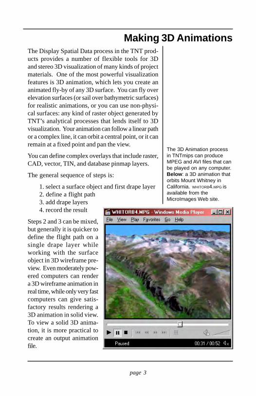
The 3D Animation processin TNTmips can produceMPEG and AVI files that canbe played on any computer.Below: a 3D animation thatorbits Mount Whitney inCalifornia. WHITORB4.MPG isavailable from theMicroImages Web site.
page 4
Creating 3D Animations
A 3D AnimationThe sample data distributed with the TNT productsincludes a simple 3D animation layout. Launch theDisplay Spatial Data process and select Open 3DAnimation from the Open menu. Use the standardselection tools to get the PAGE4 layout from the LAY-OUTS project file in the 3DSIM folder.
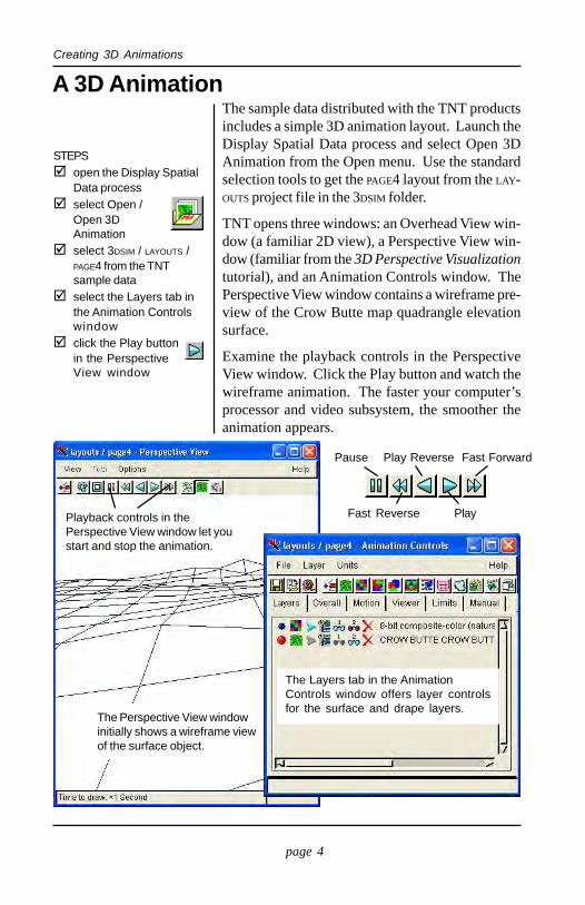
TNT opens three windows: an Overhead View win-dow (a familiar 2D view), a Perspective View win-dow (familiar from the 3D Perspective Visualizationtutorial), and an Animation Controls window. ThePerspective View window contains a wireframe pre-view of the Crow Butte map quadrangle elevationsurface.
Examine the playback controls in the PerspectiveView window. Click the Play button and watch thewireframe animation. The faster your computer’sprocessor and video subsystem, the smoother theanimation appears.
STEPSopen the Display SpatialData processselect Open /Open 3DAnimationselect 3DSIM / LAYOUTS /PAGE4 from the TNTsample dataselect the Layers tab inthe Animation Controlswindowclick the Play buttonin the PerspectiveView window
The Layers tab in the AnimationControls window offers layer controlsfor the surface and drape layers.
The Perspective View windowinitially shows a wireframe viewof the surface object.
Playback controls in thePerspective View window let youstart and stop the animation.
Pause Play Reverse Fast Forward
Fast Reverse Play
page 5
Creating 3D Animations
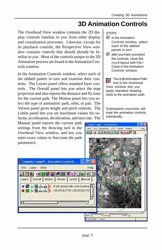
3D Animation ControlsThe Overhead View window contains the 2D dis-play controls familiar to you from other displayand visualization processes. Likewise, except forits playback controls, the Perspective View win-dow contains controls that should already be fa-miliar to you. Most of the controls unique to the 3DAnimation process are found in the Animation Con-trols window.
In the Animation Controls window, select each ofthe tabbed panels in turn and examine their con-tents. The Layers panel offers standard layer con-trols. The Overall panel lets you select the mapprojection and also reports the distance and fly timefor the current path. The Motion panel lets you se-lect the type of animation: path, orbit, or pan. TheViewer panel gives height and pitch controls. TheLimits panel lets you set maximum values for ve-locity, acceleration, deceleration, and turn rate. TheManual panel reports the current pathsettings from the drawing tool in theOverhead View window, and lets youenter exact values to fine-tune the pathparameters.
STEPSin the AnimationControls window, selecteach of the tabbedpanels in turnafter you have surveyedthe controls, close thePAGE4 layout with File /Close in the AnimationControls window
The Edit Animation Pathtool in the Overhead
View window lets youapply standard drawingtools to the animation path.
The Edit AnimationPath tool lets youchange the animationpath.
Subsequent exercises willtreat the animation controlsindividually.
page 6
Creating 3D Animations
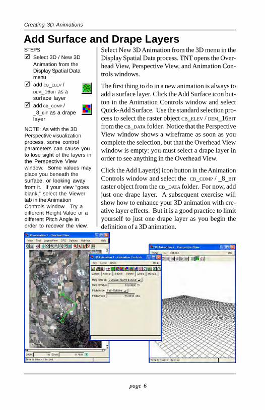
Add Surface and Drape LayersSelect New 3D Animation from the 3D menu in theDisplay Spatial Data process. TNT opens the Over-head View, Perspective View, and Animation Con-trols windows.
The first thing to do in a new animation is always toadd a surface layer. Click the Add Surface icon but-ton in the Animation Controls window and selectQuick-Add Surface. Use the standard selection pro-cess to select the raster object CB_ELEV / DEM_16BIT
from the CB_DATA folder. Notice that the PerspectiveView window shows a wireframe as soon as youcomplete the selection, but that the Overhead Viewwindow is empty: you must select a drape layer inorder to see anything in the Overhead View.
Click the Add Layer(s) icon button in the AnimationControls window and select the CB_COMP / _8_BIT
raster object from the CB_DATA folder. For now, addjust one drape layer. A subsequent exercise willshow how to enhance your 3D animation with cre-ative layer effects. But it is a good practice to limityourself to just one drape layer as you begin thedefinition of a 3D animation.
STEPSSelect 3D / New 3DAnimation from theDisplay Spatial Datamenuadd CB_ELEV /DEM_16BIT as asurface layeradd CB_COMP /_8_BIT as a drapelayer
NOTE: As with the 3DPerspective visualizationprocess, some controlparameters can cause youto lose sight of the layers inthe Perspective Viewwindow. Some values mayplace you beneath thesurface, or looking awayfrom it. If your view “goesblank,” select the Viewertab in the AnimationControls window. Try adifferent Height Value or adifferent Pitch Angle inorder to recover the view.
page 7
Creating 3D Animations
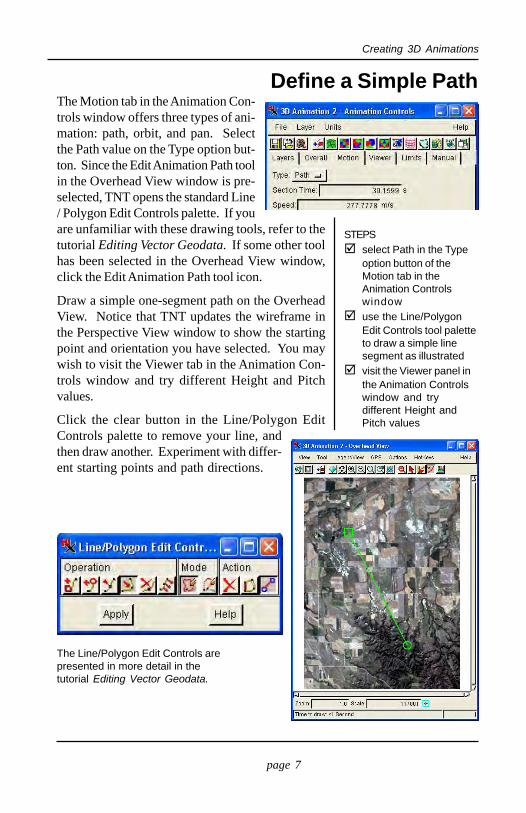
Define a Simple PathThe Motion tab in the Animation Con-trols window offers three types of ani-mation: path, orbit, and pan. Selectthe Path value on the Type option but-ton. Since the Edit Animation Path toolin the Overhead View window is pre-selected, TNT opens the standard Line/ Polygon Edit Controls palette. If youare unfamiliar with these drawing tools, refer to thetutorial Editing Vector Geodata. If some other toolhas been selected in the Overhead View window,click the Edit Animation Path tool icon.
Draw a simple one-segment path on the OverheadView. Notice that TNT updates the wireframe inthe Perspective View window to show the startingpoint and orientation you have selected. You maywish to visit the Viewer tab in the Animation Con-trols window and try different Height and Pitchvalues.
Click the clear button in the Line/Polygon EditControls palette to remove your line, andthen draw another. Experiment with differ-ent starting points and path directions.
STEPSselect Path in the Typeoption button of theMotion tab in theAnimation Controlswindowuse the Line/PolygonEdit Controls tool paletteto draw a simple linesegment as illustratedvisit the Viewer panel inthe Animation Controlswindow and trydifferent Height andPitch values
The Line/Polygon Edit Controls arepresented in more detail in thetutorial Editing Vector Geodata.
page 8
Creating 3D Animations
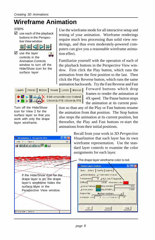
Wireframe AnimationUse the wireframe mode for all interactive setup andtesting of your animation. Wireframe renderingsrequire much less processing than solid view ren-derings, and thus even moderately-powered com-puters can give you a reasonable wireframe anima-tion effect.
Familiarize yourself with the operation of each ofthe playback buttons in the Perspective View win-dow. First click the Play button, which runs theanimation from the first position to the last. Thenclick the Play Reverse button, which runs the sameanimation backwards. Try the Fast Reverse and Fast
Forward buttons which dropframes to render the animation at4X speed. The Pause button stopsthe animation at its current posi-
tion so than any of the Play or Fast buttons resumethe animation from that position. The Stop buttonalso stops the animation at its current position, butthereafter, the Play and Fast buttons re-start theanimations from their initial positions.
Recall from your work in 3D PerspectiveVisualization that each layer has its ownwireframe representation. Use the stan-dard layer controls to examine the colorassignments for each layer.
STEPSuse each of the playbackbuttons in the Perspec-tive View window
use the layercontrols in theAnimation Controlswindow to turn off theHide/Show icon for thesurface layer
Turn off the Hide/Showicon for View 2 for thesurface layer so that youwork with only the drapelayer wireframe.
If the Hide/Show icon for thedrape layer is on, the drapelayer’s wireframe hides thesurface layer in thePerspective View window.
The drape layer wireframe color is red.
page 9
Creating 3D Animations
Improve Rendering SpeedOnly the fastest computers will be able to render a3D animation so that you will be able to view theanimation effect in solid view mode. Normally,you should define your 3D animation in wireframemode and then use the Record Movie buttonto create an MPEG or AVI file for later viewing.A long complex animation that uses multiple surfacelayers may take an hour or more to process into anoutput animation file (see page 14).
If you have a very fast computer, you may want tosee solid renderings of your 3D animations. Theprocess attempts to maintain the specified veloc-ity for viewing, and when the computer is not fastenough, the process drops frames. In the most se-vere case, the process may render only the initialand final frames, dropping everything in between.
You can take some measures to relieve some pro-cessing burden and produce a smoother 3D anima-tion:
• Resize the Perspective View window. Thesmaller the window, the lower the demands onprocessing power.
• Turn off foreground smoothing. Foregroundsmoothing blurs the blocky, discrete imagepixels near the viewer. It improves the appear-ance, but it increases the processing load.
• Use constant altitude instead of constant heightabove the surface (Viewer panel in the Anima-tion Controls window).
• Hide the drape layers with the layer controls inthe Layers tab of the Animation Controls win-dow
• Even the wireframe animation can be improvedif you use a lower wireframe sampling rate
Many other generaloptimization tricks apply tothe 3D Animation process(and to all TNT processes):• get a faster computer• pre-process 24-bit color if
you work in 8-bit colormode
• add more RAM• get a faster video
subsystem
To get a preview of thesolid view before record-ing, you can pause thewireframe animation atvarious points along theway and temporarily turnon the Solid View. Checkthe appearance of the fullyrendered “snapshot,” andthen resume the animationin wireframe mode.
page 10
Creating 3D Animations
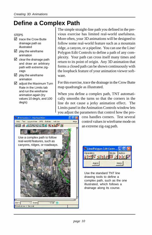
Define a Complex PathThe simple straight-line path you defined in the pre-vious exercise has limited real-world usefulness.More often, your 3D animations will be designed tofollow some real-world feature such as a mountainridge, a canyon, or a pipeline. You can use the Line/Polygon Edit Controls to define a path of any com-plexity. Your path can cross itself many times andreturn to its point of origin. Any 3D animation thatforms a closed path can be shown continuously withthe loopback feature of your animation viewer soft-ware.
For this exercise, trace the drainage in the Crow Buttemap quadrangle as illustrated.
When you define a complex path, TNT automati-cally smooths the turns so that the corners in theline do not cause a jerky animation effect. TheLimits panel in the Animation Controls window letsyou adjust the parameters that control how the pro-
cess handles corners. Test severalcontrol values in wireframe mode onan extreme zig-zag path.
STEPStrace the Crow Buttedrainage path asillustratedplay the wireframeanimationclear the drainage pathand draw an arbitrarypath with extreme zig-zagsplay the wireframeanimationadjust the Maximum TurnRate in the Limits taband run the wireframeanimation again (tryvalues 10 deg/s, and 100deg/s)
Use the standard TNT linedrawing tools to define acomplex path, such as the oneillustrated, which follows adrainage along its course.
Use a complex path to followreal-world features, such ascanyons, ridges, or roadways.
page 11
Creating 3D Animations
Orbit a Central PointSTEPS
select Orbit in the Typeoption button in theMotion paneldrag and resize the circletoolplay the wireframeanimation
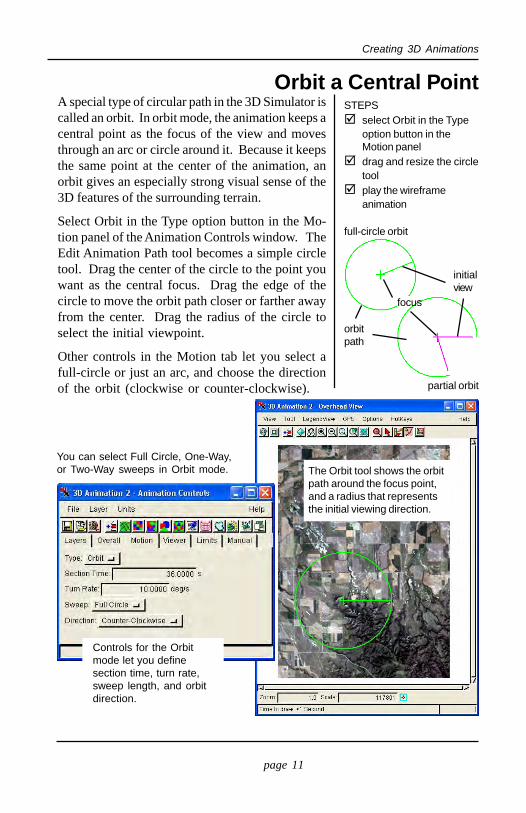
A special type of circular path in the 3D Simulator iscalled an orbit. In orbit mode, the animation keeps acentral point as the focus of the view and movesthrough an arc or circle around it. Because it keepsthe same point at the center of the animation, anorbit gives an especially strong visual sense of the3D features of the surrounding terrain.
Select Orbit in the Type option button in the Mo-tion panel of the Animation Controls window. TheEdit Animation Path tool becomes a simple circletool. Drag the center of the circle to the point youwant as the central focus. Drag the edge of thecircle to move the orbit path closer or farther awayfrom the center. Drag the radius of the circle toselect the initial viewpoint.
Other controls in the Motion tab let you select afull-circle or just an arc, and choose the directionof the orbit (clockwise or counter-clockwise).
The Orbit tool shows the orbitpath around the focus point,and a radius that representsthe initial viewing direction.
Controls for the Orbitmode let you definesection time, turn rate,sweep length, and orbitdirection.
focus
orbitpath
full-circle orbit
initialview
partial orbit
You can select Full Circle, One-Way,or Two-Way sweeps in Orbit mode.
page 12
Creating 3D Animations
Pan from a Single Viewpoint
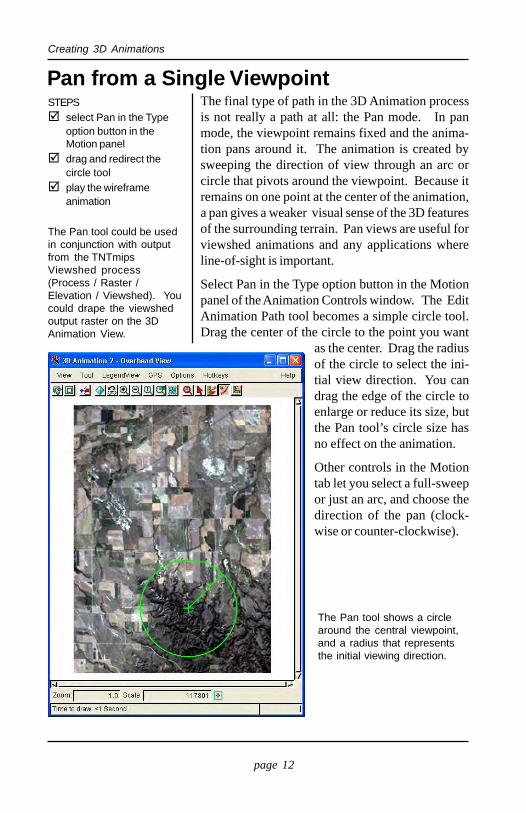
The Pan tool shows a circlearound the central viewpoint,and a radius that representsthe initial viewing direction.
STEPSselect Pan in the Typeoption button in theMotion paneldrag and redirect thecircle toolplay the wireframeanimation
The final type of path in the 3D Animation processis not really a path at all: the Pan mode. In panmode, the viewpoint remains fixed and the anima-tion pans around it. The animation is created bysweeping the direction of view through an arc orcircle that pivots around the viewpoint. Because itremains on one point at the center of the animation,a pan gives a weaker visual sense of the 3D featuresof the surrounding terrain. Pan views are useful forviewshed animations and any applications whereline-of-sight is important.
Select Pan in the Type option button in the Motionpanel of the Animation Controls window. The EditAnimation Path tool becomes a simple circle tool.Drag the center of the circle to the point you want
as the center. Drag the radiusof the circle to select the ini-tial view direction. You candrag the edge of the circle toenlarge or reduce its size, butthe Pan tool’s circle size hasno effect on the animation.
Other controls in the Motiontab let you select a full-sweepor just an arc, and choose thedirection of the pan (clock-wise or counter-clockwise).
The Pan tool could be usedin conjunction with outputfrom the TNTmipsViewshed process(Process / Raster /Elevation / Viewshed). Youcould drape the viewshedoutput raster on the 3DAnimation View.
page 13
Creating 3D Animations
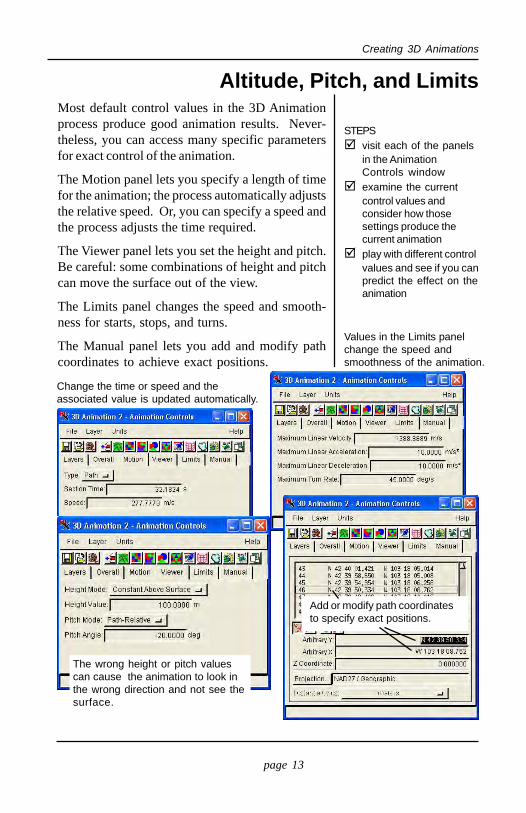
Altitude, Pitch, and LimitsMost default control values in the 3D Animationprocess produce good animation results. Never-theless, you can access many specific parametersfor exact control of the animation.
The Motion panel lets you specify a length of timefor the animation; the process automatically adjuststhe relative speed. Or, you can specify a speed andthe process adjusts the time required.
The Viewer panel lets you set the height and pitch.Be careful: some combinations of height and pitchcan move the surface out of the view.
The Limits panel changes the speed and smooth-ness for starts, stops, and turns.
The Manual panel lets you add and modify pathcoordinates to achieve exact positions.
STEPSvisit each of the panelsin the AnimationControls windowexamine the currentcontrol values andconsider how thosesettings produce thecurrent animationplay with different controlvalues and see if you canpredict the effect on theanimation
Change the time or speed and theassociated value is updated automatically.
Values in the Limits panelchange the speed andsmoothness of the animation.
The wrong height or pitch valuescan cause the animation to look inthe wrong direction and not see thesurface.
Add or modify path coordinatesto specify exact positions.
page 14
Creating 3D Animations
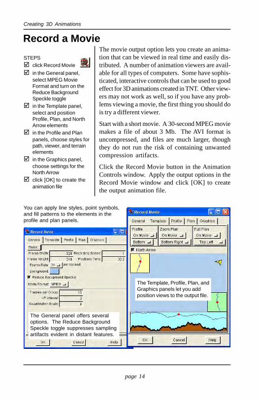
Record a MovieThe movie output option lets you create an anima-tion that can be viewed in real time and easily dis-tributed. A number of animation viewers are avail-able for all types of computers. Some have sophis-ticated, interactive controls that can be used to goodeffect for 3D animations created in TNT. Other view-ers may not work as well, so if you have any prob-lems viewing a movie, the first thing you should dois try a different viewer.
Start with a short movie. A 30-second MPEG moviemakes a file of about 3 Mb. The AVI format isuncompressed, and files are much larger, thoughthey do not run the risk of containing unwantedcompression artifacts.
Click the Record Movie button in the AnimationControls window. Apply the output options in theRecord Movie window and click [OK] to createthe output animation file.
STEPSclick Record Moviein the General panel,select MPEG MovieFormat and turn on theReduce BackgroundSpeckle togglein the Template panel,select and positionProfile, Plan, and NorthArrow elementsin the Profile and Planpanels, choose styles forpath, viewer, and terrainelementsin the Graphics panel,choose settings for theNorth Arrowclick [OK] to create theanimation file
You can apply line styles, point symbols,and fill patterns to the elements in theprofile and plan panels.
The Template, Profile, Plan, andGraphics panels let you addposition views to the output file.
The General panel offers severaloptions. The Reduce BackgroundSpeckle toggle suppresses samplingartifacts evident in distant features.
page 15
Creating 3D Animations
Creative Layer EffectsDesign your animations by beginning with short,simple animations. After you have established thebasic look and have determined which parameterswork best, you are ready to add multiple drape lay-ers: images, vectors, CAD, TIN, and databasepinmaps. You can even add GeoFormula and SMLlayers. Use styles for point, line, and polygon ele-ments. Of course you may wish to experiment withother 2D and 3D visualization features in the Dis-play Spatial Data process in order to find the lookyou want. In particular, consider using Shaded Re-lief effects by using the surface layer for shadedrelief information also.
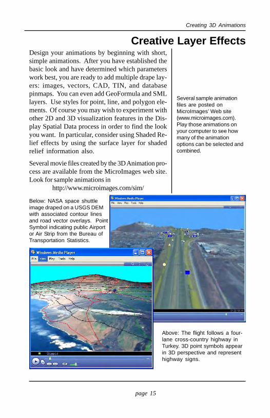
Several movie files created by the 3D Animation pro-cess are available from the MicroImages web site.Look for sample animations in
http://www.microimages.com/sim/
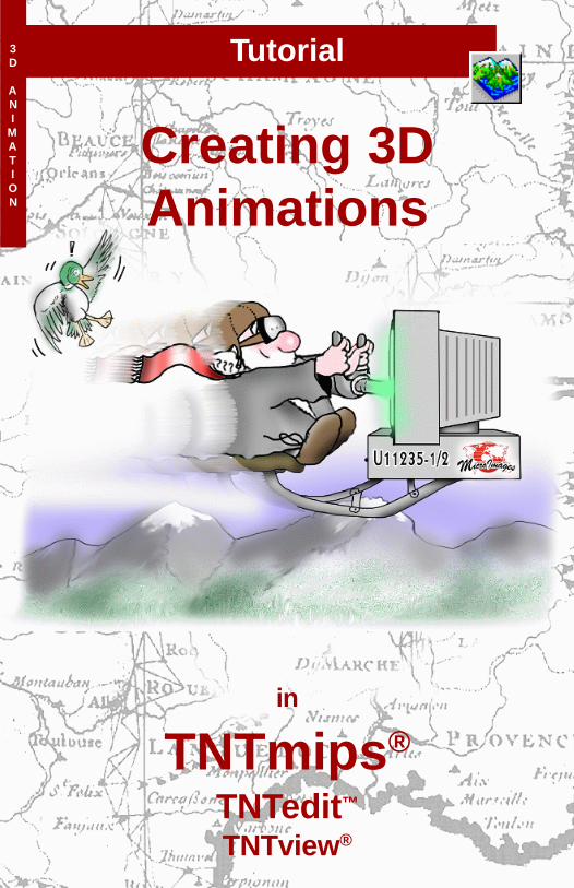
Below: NASA space shuttleimage draped on a USGS DEMwith associated contour linesand road vector overlays. PointSymbol indicating public Airportor Air Strip from the Bureau ofTransportation Statistics.
Above: The flight follows a four-lane cross-country highway inTurkey. 3D point symbols appearin 3D perspective and representhighway signs.
Several sample animationfiles are posted onMicroImages’ Web site(www.microimages.com).Play those animations onyour computer to see howmany of the animationoptions can be selected andcombined.
Voice: (402)477-9554www.microimages.com
Advanced Software for Geospatial Analysis 3D
ANI
MATION
MicroImages, Inc. publishes a complete line of professional software for advancedgeospatial data visualization, analysis, and publishing. Contact us or visit our web site fordetailed product information.TNTmips TNTmips is a professional system for fully integrated GIS, image analysis,
CAD, TIN, desktop cartography, and geospatial database management.TNTedit TNTedit provides interactive tools to create, georeference, and edit vector, image,
CAD, TIN, and relational database project materials in a wide variety of formats.TNTview TNTview has the same powerful display features as TNTmips and is perfect for
those who do not need the technical processing and preparation features of TNTmips.TNTatlas TNTatlas lets you publish and distribute your spatial project materials on CD-
ROM at low cost. TNTatlas CDs can be used on any popular computing platform.TNTserver TNTserver lets you publish TNTatlases on the Internet or on your intranet.
Navigate through geodata atlases with your web browser and the TNTclient Java applet.TNTlite TNTlite is a free version of TNTmips for students and professionals with small
projects. You can download TNTlite from MicroImages’ web site, or you can orderTNTlite on CD-ROM.
altitude ................................................ 9Animation Controls window .......... 4, 5AVI output ........................................ 14background speckle ........................... 14drape layers ........................................ 6Edit Animation Path ........................... 5foreground smoothing ......................... 9height and pitch ............................ 7, 13improving speed ................................. 9layers panel ......................................... 5limits panel ............................. 5, 10, 13line/polygon edit controls ................... 7line-of-sight animations .................... 12making 3D animations ........................ 3manual panel ................................. 5, 13minimum turn rate ............................ 10motion panel ........................ 5, 7, 11-13mpeg output ..................................... 14multiple layers .................................. 15new 3D animation ............................... 4
Indexnorth arrow ....................................... 14optimization ....................................... 9orbit .................................................. 11overall panel ........................................ 5pan .................................................... 12path ..................................... 5, 7, 10, 13pitch and height ............................ 7, 13plan view .......................................... 14play animation .................................... 4playback controls ........................... 4, 8prerequisite skills ................................ 2profile view ....................................... 14record a movie ................................... 14sample data ......................................... 2speed improvement ............................ 9surface layers ...................................... 6TNTlite mode ..................................... 2viewer panel .................................. 5, 13watershed animation ......................... 12wireframe animation ................... 3, 4, 8
Recommended