iii
TRANSIENT RESPONSE ANALYSIS FOR DC-DC BOOST CONVERTER
CHARLES MULING ANAK LIBAU
A project report submitted in partial
fulfillment of the requirement for the award of the
Master of Electrical Engineering
Faculty of Electrical and Electronic Engineering
Universiti Tun Hussein Onn Malaysia
JULY 2012
vii
ABSTRACT
DC-DC Boost Converter and Hybrid Posicast Controller is developed and simulated
using MATLAB Simulink software. DC-DC Boost converter has a very high
overshoot and a very high settling time which produce oscillated output response. In
order to overcome this weakness, Hybrid Posicast Controller is used in order to
regulate the output voltage to a desire value. Hybrid Posicast Controller operated
within the feedback loop of the system. Transfer function of DC-DC Boost Converter
are derived and Posicast elements of and dT can be calculated directly from the
transfer function. Single gain, K is used in order to eliminate the overshoot and
minimize the settling time. Simulation results show that Hybrid Posicast Controller
effectively regulate the output voltage to a desire value even though load resistance
and duty cycle have been changed with a various values. DC-DC Boost Converter
using Posicast Controller has an excellent performance to overcome unregulated
input voltage, eliminate overshoot and minimize the settling time.
viii
ABSTRACT
DC-DC Boost Converter dan Hybrid Posicast Controller dibina dan disimulasikan
dengan menggunakan perisian MATLAB Simulink. DC-DC Boost Converter
mempunyai lajakan isyarat yang sangat tinggi dan mengambil masa yang sangat
lama untuk mencapai takat stabil yang mana keadaan ini menghasilkan sambutan
keluaran yang berayun. Untuk mengatasi kelemahan ini, Hybrid Posicast Controller
digunakan untuk menstabilkan voltan keluaran kepada nilai yang dikehendaki.
Hybrid Posicast Controller beroperasi di dalam gelung tertutup sistem. Unsur-unsur
Posicast, dan dT boleh dikira terus dari rangkap pindah DC-DC Boost Converter.
Single gain, K digunakan untuk menghapuskan lajakan isyarat dan meminimumkan
masa untuk mencapai takat stabil. Keputusan simulasi menunjukkan bahawa Hybrid
Posicast Controller berkesan untuk menstabilkan voltan keluaran kepada nilai yang
dikehendaki walaupun rintangan beban dan kitar kerja telah berubah dengan pelbagai
nilai. DC-DC Boost Converter menggunakan Hybrid Posicast Controller mempunyai
prestasi yang sangat baik untuk menangani voltan masukan yang berubah-ubah,
menghapuskan lajakan isyarat dan meminimumkan masa untuk mencapai takat
stabil.
ix
CONTENTS
TITLE i
DECLARATION ii
DEDICATION v
ACKNOWLEDGEMENT vi
ABSTRACT vii
CONTENTS ix
LIST OF TABLES xii
LIST OF FIGURES xiv
CHAPTER 1 INTRODUCTION 1
1.1 Problem statement 2
1.2 Project objectives 2
1.3 Project scope 2
CHAPTER 2 LITERATURE REVIEW 3
2.1 Previous research 3
2.2 Power electronics circuit 5
2.3 Control systems 6
2.3.1 Overview of control systems 6
x
2.3.2 Elements used in control systems 8
2.3.2.1 Transfer function of control
systems 8
2.3.2.2 Block diagram of control
systems 9
2.3.2.3 Time domain response 12
2.4 Converters 17
2.5 DC-DC converter 19
2.5.1 General overview of DC-DC
converter 19
2.5.2 DC-DC converter switching 20
2.6 Boost converter 24
2.6.1 Boost converter overview 24
2.6.2 Switch closed analysis 26
2.6.3 Switch open analysis 27
2.7 Classical posicast controller 35
2.8 Hybrid posicast controller 36
CHAPTER 3 METHODOLOGY 39
3.1 Modeling of DC-DC BC 41
3.1.1 State space analysis 41
xi
3.1.2 Transfer function of DC-DC BC 47
3.2 Modeling of HPC 50
CHAPTER 4 RESULT AND ANALYSIS 53
4.1 Ideal DC-DC BC circuit parameters 53
4.1.1 DC-DC BC 9V 57
4.1.2 DC-DC BC 12V 58
4.1.3 DC-DC BC 18V 59
4.2 Effect of Vi 61
4.2.1 DC-DC BC with Vi = 9V 63
4.2.2 DC-DC BC with Vi = 12V 64
4.2.3 DC-DC BC with Vi = 18V 65
4.3 Effect of RL 66
4.3.1 DC-DC BC with RL = 25Ω 68
4.3.2 DC-DC BC with RL = 50Ω 69
4.3.3 DC-DC BC with RL = 75Ω 70
CHAPTER 5 CONCLUSION AND RECOMMENDATION 72
REFERENCES 73

xii
TABLES
2.1 Boost converter using different types of controller 3
2.2 Transfer function parameters 8
2.3 Second order response 14
2.4 Parameters used to analyze performance characteristics 16
2.5 Classifications of converters 18
4.1 Initial parameters of DC-DC BC 54
4.2 DC-DC BC output voltage and output current 56
4.3 Parameter of DC-DC BC 9V 57
4.4 Simulation result of DC-DC BC 9V 58
4.5 Parameter of DC-DC BC 12V 58
4.6 Simulation result of DC-DC BC 9V 59
4.7 Parameter of DC-DC BC 18V 60
4.8 Simulation result of DC-DC BC 9V 60
4.9 DC-DC BC using HPC parameters 62
4.10 Parameter of DC-DC BC with 25LR 68
4.11 Simulation result of DC-DC BC with 25LR 69

xiii
4.12 Parameter of DC-DC BC with 50LR 69
4.13 Simulation result of DC-DC BC with RL = 50Ω 70
4.14 Parameter of DC-DC BC with 75LR 71
4.15 Simulation result of DC-DC BC with 75LR 71
xiv
FIGURES
2.1 Basic converter system 7
2.2 Two converters are used in a multistep process 7
2.3 Block system 10
2.4 Cascade form 10
2.5 Simplified cascade form 10
2.6 Parallel form 11
2.7 Simplified parallel form 11
2.8 Feedback form 11
2.9 Simplified feedback form 12
2.10 Time domain response 13
2.11 Second order response with unit step function input 15
2.12 Underdamped second order response 15
2.13 Basic converter system 17
2.14 Two converters are used in a multistep process 18
2.15 General DC-DC converter block diagram 19
2.16 Switching ON and OFF of DC-DC converter 21
2.17 ONt and OFFt pulse 21
xv
2.18 Continuous Conduction Mode 22
2.19 Discontinuous Conduction Mode 23
2.20 Li and LV when inductor looks like short circuit 23
2.21 Boost converter circuit 24
2.22 Boost converter circuit with switch closed 25
2.23 Boost converter circuit with switch opened 25
2.24 LV and Li signal for switch closed condition 27
2.25 and L LV i signal for switch closed condition 29
2.26 VL, iL, iD and iC in CCM 32
2.27 , , and L L D cV i i i in CCM with ripple factor 34
2.28 Step response of lightly damped system 35
2.29 Classical half-cycle posicast structure 36
2.30 Proposed hybrid feedback control using posicast 37
3.1 Flow chart of project 38
3.2 Ideal DC-DC BC 41
3.3 Equivalent circuit DC-DC BC in CCM 43
3.4 MATLAB Simulink for ideal DC-DC BC circuit 50
3.5 Ideal DC-DC BC subsystem 50
3.6 MATLAB Simulink for HPC 52
3.7 MATLAB Simulink for ideal DC-DC BC subsystem
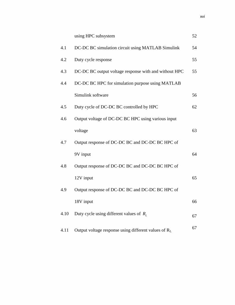
xvi
using HPC subsystem 52
4.1 DC-DC BC simulation circuit using MATLAB Simulink 54
4.2 Duty cycle response 55
4.3 DC-DC BC output voltage response with and without HPC 55
4.4 DC-DC BC HPC for simulation purpose using MATLAB
Simulink software 56
4.5 Duty cycle of DC-DC BC controlled by HPC 62
4.6 Output voltage of DC-DC BC HPC using various input
voltage 63
4.7 Output response of DC-DC BC and DC-DC BC HPC of
9V input 64
4.8 Output response of DC-DC BC and DC-DC BC HPC of
12V input 65
4.9 Output response of DC-DC BC and DC-DC BC HPC of
18V input 66
4.10 Duty cycle using different values of LR 67
4.11 Output voltage response using different values of RL 67
1
CHAPTER 1
INTRODUCTION
Converters required power electronic circuit in order to match the voltage and current
requirements of the load to those of the source. Converters are classified by the
relationship between input and output (Hart D. W., 2011).
DC-DC converters are used to convert the unregulated DC input to a
controlled DC output at a desire voltage output. It classified as a regulator as it useful
when a load requires a specified dc voltage or current but the source is at a different
or unregulated dc value. It used widely in dc motor drive application (Quansheng Xu,
2005) and it provides smooth acceleration control, high efficiency and fast dynamic
response (Fathi S. J., 2011).
In order to compensate any disturbance or error in the converter system,
control system has been designed. Control design for any system involves a
mathematical description of the relation among inputs to the process, state variables,
and output. This control parameters will be presented in the form of mathematical
equations which describe behavior of the system is called model of the system.
The advantages/primary reasons of building control system are to get power
amplification, remote control, convenience of input form and compensation for
disturbance (Nise N. S., 2000).
2
1.1 Problem statement
DC-DC Boost converter (DC-DC BC) also known as a regulator was a designed
power electronics circuit which capable to regulate unregulated dc input to a desire
voltage output. The dynamics of the DC-DC converter can be described as nonlinear
and lightly damped (Feng, Q. et al., 2002). The converter is nonlinear lightly damped
dynamics, which are described as a function of load parameters, duty cycle and make
the control design difficult and challenging one (Krauter, S. C. W., 2006). Boost
converter has a limitation as it has a characteristic of overshoot in the step response of
lightly damped systems.
PWM signal with high switching is used in order to minimize output voltage
ripple and Hybrid Posicast Controller (HPC) to overcome DC-DC BC limitation as
HPC able to produce a good transient state performance.
1.2 Project objectives
The objectives of this project are:
i) To develop ideal DC-DC BC in Continuous Conduction Mode (CCM).
ii) To develop HPC.
iii) To analyze transient response of DC-DC BC.
1.3 Project scope
The scope of this project is to develop ideal (without parasitic elements) DC-DC BC
in CCM and then develop HPC as a controller. DC-DC BC using HPC will be
simulate using MATLAB Simulink software in order to analyze transient response
characteristics.
3
CHAPTER 2
LITERATUR REVIEW
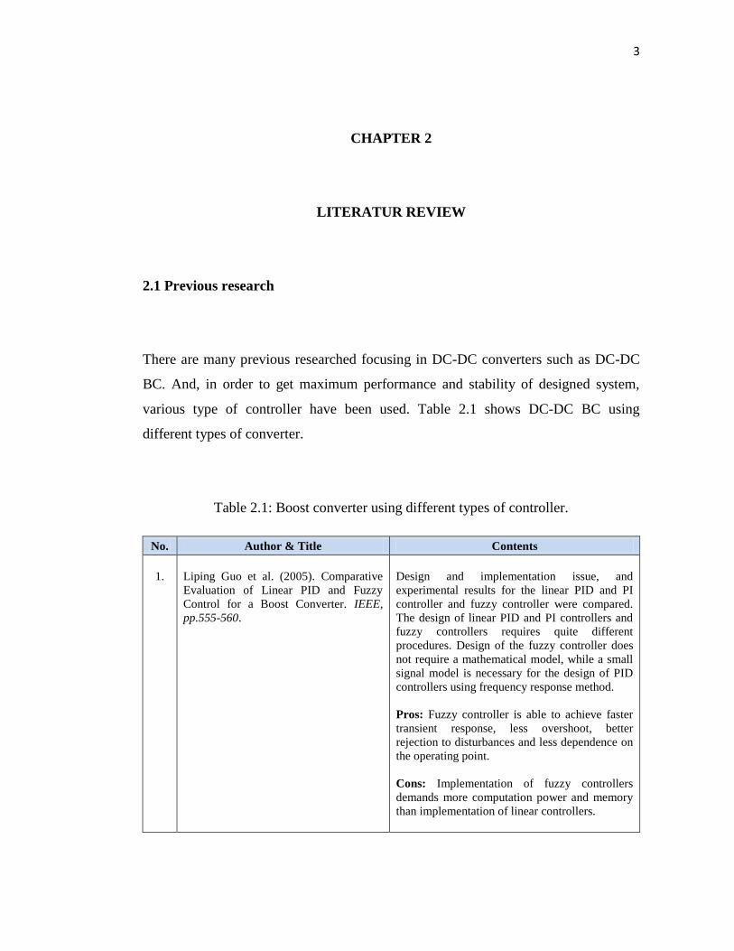
2.1 Previous research
There are many previous researched focusing in DC-DC converters such as DC-DC
BC. And, in order to get maximum performance and stability of designed system,
various type of controller have been used. Table 2.1 shows DC-DC BC using
different types of converter.
Table 2.1: Boost converter using different types of controller.
No. Author & Title Contents
1.
Liping Guo et al. (2005). Comparative
Evaluation of Linear PID and Fuzzy
Control for a Boost Converter. IEEE,
pp.555-560.
Design and implementation issue, and
experimental results for the linear PID and PI
controller and fuzzy controller were compared.
The design of linear PID and PI controllers and
fuzzy controllers requires quite different
procedures. Design of the fuzzy controller does
not require a mathematical model, while a small
signal model is necessary for the design of PID
controllers using frequency response method.
Pros: Fuzzy controller is able to achieve faster
transient response, less overshoot, better
rejection to disturbances and less dependence on
the operating point.
Cons: Implementation of fuzzy controllers
demands more computation power and memory
than implementation of linear controllers.
4
Table 2.1 (continued)
No. Author & Title Contents
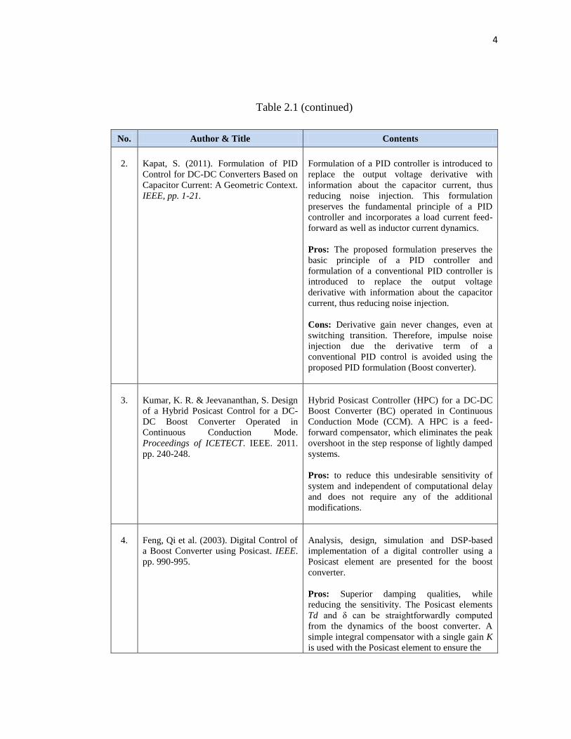
2.
Kapat, S. (2011). Formulation of PID
Control for DC-DC Converters Based on
Capacitor Current: A Geometric Context.
IEEE, pp. 1-21.
Formulation of a PID controller is introduced to
replace the output voltage derivative with
information about the capacitor current, thus
reducing noise injection. This formulation
preserves the fundamental principle of a PID
controller and incorporates a load current feed-
forward as well as inductor current dynamics.
Pros: The proposed formulation preserves the
basic principle of a PID controller and
formulation of a conventional PID controller is
introduced to replace the output voltage
derivative with information about the capacitor
current, thus reducing noise injection.
Cons: Derivative gain never changes, even at
switching transition. Therefore, impulse noise
injection due the derivative term of a
conventional PID control is avoided using the
proposed PID formulation (Boost converter).
3.
Kumar, K. R. & Jeevananthan, S. Design
of a Hybrid Posicast Control for a DC-
DC Boost Converter Operated in
Continuous Conduction Mode.
Proceedings of ICETECT. IEEE. 2011.
pp. 240-248.
Hybrid Posicast Controller (HPC) for a DC-DC
Boost Converter (BC) operated in Continuous
Conduction Mode (CCM). A HPC is a feed-
forward compensator, which eliminates the peak
overshoot in the step response of lightly damped
systems.
Pros: to reduce this undesirable sensitivity of
system and independent of computational delay
and does not require any of the additional
modifications.
4.
Feng, Qi et al. (2003). Digital Control of
a Boost Converter using Posicast. IEEE.
pp. 990-995.
Analysis, design, simulation and DSP-based
implementation of a digital controller using a
Posicast element are presented for the boost
converter.
Pros: Superior damping qualities, while
reducing the sensitivity. The Posicast elements
Td and δ can be straightforwardly computed
from the dynamics of the boost converter. A
simple integral compensator with a single gain K
is used with the Posicast element to ensure the
5
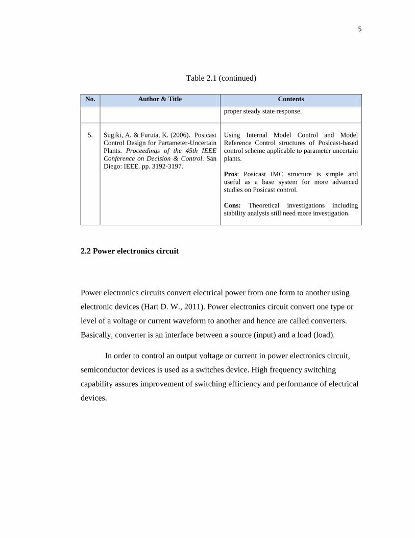
Table 2.1 (continued)
No. Author & Title Contents
proper steady state response.
5.
Sugiki, A. & Furuta, K. (2006). Posicast
Control Design for Partameter-Uncertain
Plants. Proceedings of the 45th IEEE
Conference on Decision & Control. San
Diego: IEEE. pp. 3192-3197.
Using Internal Model Control and Model
Reference Control structures of Posicast-based
control scheme applicable to parameter uncertain
plants.
Pros: Posicast IMC structure is simple and
useful as a base system for more advanced
studies on Posicast control.
Cons: Theoretical investigations including
stability analysis still need more investigation.
2.2 Power electronics circuit
Power electronics circuits convert electrical power from one form to another using
electronic devices (Hart D. W., 2011). Power electronics circuit convert one type or
level of a voltage or current waveform to another and hence are called converters.
Basically, converter is an interface between a source (input) and a load (load).
In order to control an output voltage or current in power electronics circuit,
semiconductor devices is used as a switches device. High frequency switching
capability assures improvement of switching efficiency and performance of electrical
devices.
6
2.3 Control systems
2.3.1 Overview of control systems
A control system consists of subsystems and processes (or plants) assembled for the
purpose of controlling the outputs of the processes (Nise N. S., 2000). With existing
of control systems, most of difficulty in controlling a process has been overcome. For
example lifting heavy objects using forklift and move a huge antennas to desire grid
with highly precision positioning.
There are four primary reasons of control design namely power amplification,
remote control, convenience of input form and compensation for disturbances (Nise
N. S., 2000).
Power amplification is needed as sometimes a control system needs to
produce certain level of power or normally called power gain, in order to activate a
system such as rotate an antennas which requires large amount of power.
Remote control basically used in a robot control technology. It compensates
human disabilities such as using a remote control robot for underwater/deep sea
scientific research.
Control systems can also be used to provide convenience by changing the
form of the input (Nise N. S., 2000). For example, in forklift operation, the input is a
weight detector and the output is a torque (motor).
Control systems have a capability to compensate for disturbances. That mean,
even there are disturbance of input signal, a process or a system still able to produce a
correct output. In a process of positioning an antenna for example, if antenna position
7
changes because of a wind forces, the system should be able to detect the disturbance
and correct the antenna’s position.
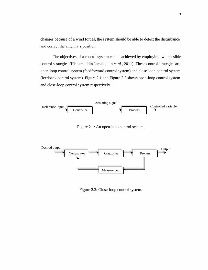
The objectives of a control system can be achieved by employing two possible
control strategies (Hishamuddin Jamaluddin et al., 2011). These control strategies are
open-loop control system (feedforward control system) and close-loop control system
(feedback control system). Figure 2.1 and Figure 2.2 shows open-loop control system
and close-loop control system respectively.
Figure 2.1: An open-loop control system.
Figure 2.2: Close-loop control system.
Controlled variable Reference input Controller Process
Actuating signal
Output Desired output
C(s) Comparator
Measurement
Process Controller
8
2.3.2 Elements used in control systems
There are many elements in control systems that need to be considered when develop
and analyze a process. Thus, an efficient and reliable system can be produce together
with desire control method.
In order to analyze DC-DC BC using HPC, three major elements need to
considered,
i) Transfer function.
ii) Control system block diagram.
iii) Time domain response.
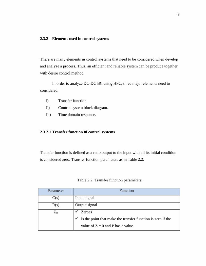
2.3.2.1 Transfer function 0f control systems
Transfer function is defined as a ratio output to the input with all its initial condition
is considered zero. Transfer function parameters as in Table 2.2.
Table 2.2: Transfer function parameters.
Parameter Function
C(s) Input signal
R(s) Output signal
Zm Zeroes
Is the point that make the transfer function is zero if the
value of Z = 0 and P has a value.
9
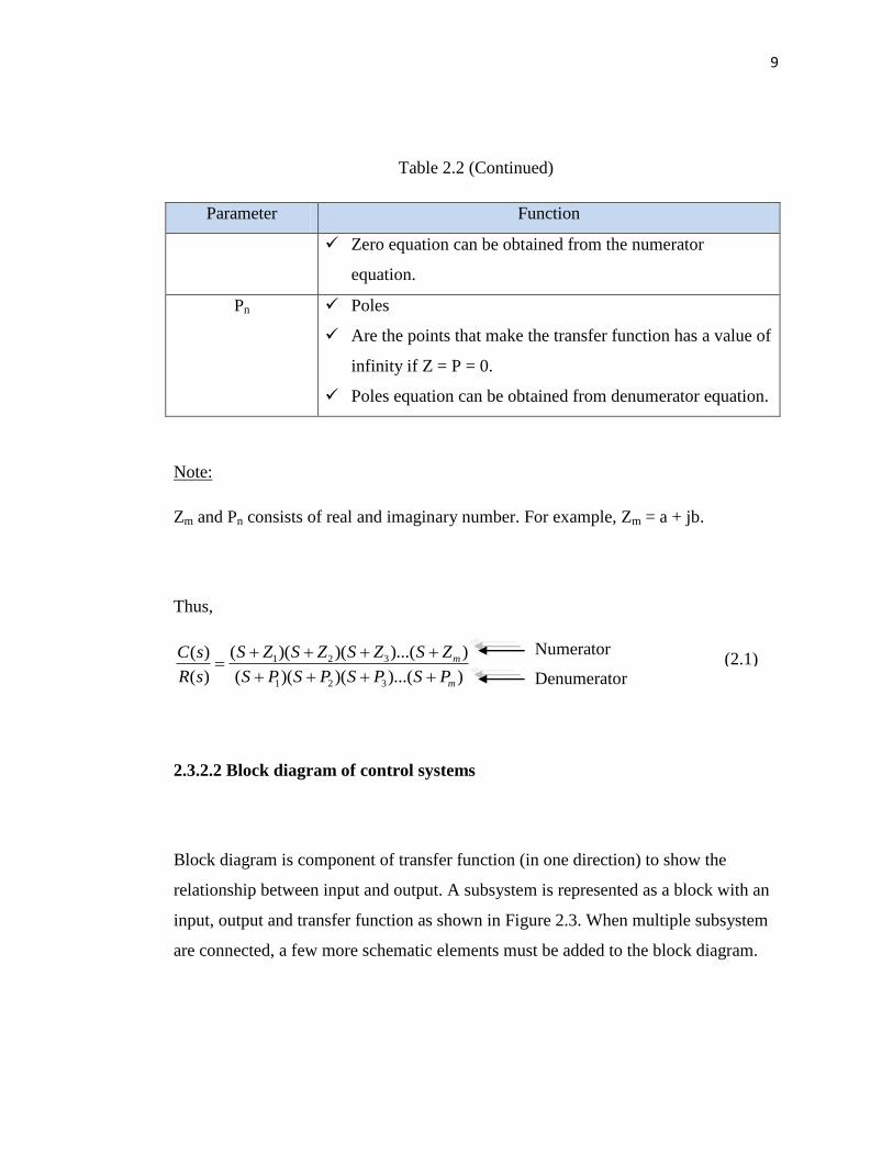
Table 2.2 (Continued)
Parameter Function
Zero equation can be obtained from the numerator
equation.
Pn Poles
Are the points that make the transfer function has a value of
infinity if Z = P = 0.
Poles equation can be obtained from denumerator equation.
Note:
Zm and Pn consists of real and imaginary number. For example, Zm = a + jb.
Thus,
1 2 3
1 2 3
( )( )( )...( )( )
( ) ( )( )( )...( )
m
m
S Z S Z S Z S ZC s
R s S P S P S P S P
2.3.2.2 Block diagram of control systems
Block diagram is component of transfer function (in one direction) to show the
relationship between input and output. A subsystem is represented as a block with an
input, output and transfer function as shown in Figure 2.3. When multiple subsystem
are connected, a few more schematic elements must be added to the block diagram.
Numerator
Denumerator (2.1)
10
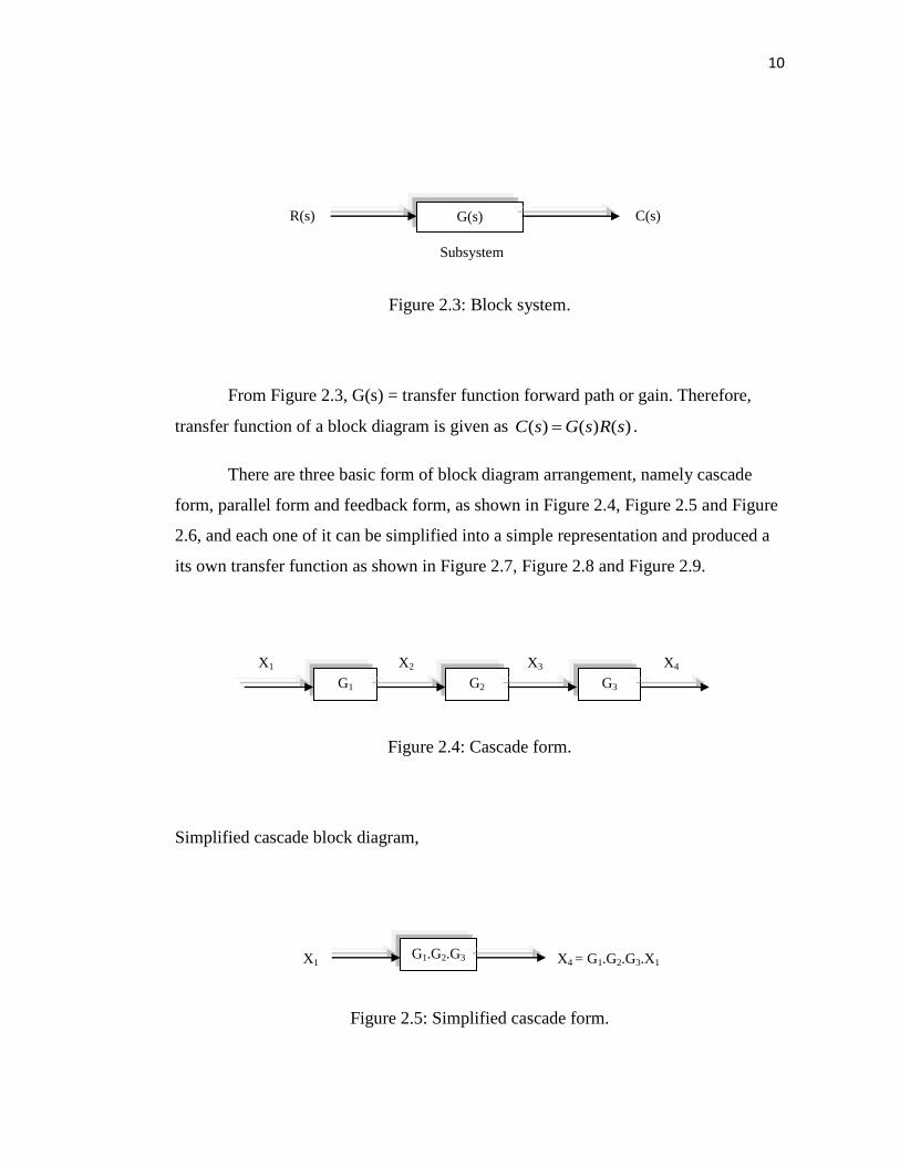
Figure 2.3: Block system.
From Figure 2.3, G(s) = transfer function forward path or gain. Therefore,
transfer function of a block diagram is given as ( ) ( ) ( )C s G s R s .
There are three basic form of block diagram arrangement, namely cascade
form, parallel form and feedback form, as shown in Figure 2.4, Figure 2.5 and Figure
2.6, and each one of it can be simplified into a simple representation and produced a
its own transfer function as shown in Figure 2.7, Figure 2.8 and Figure 2.9.
Figure 2.4: Cascade form.
Simplified cascade block diagram,
Figure 2.5: Simplified cascade form.
G(s) R(s) C(s)
Subsystem
G1.G2.G3 X1 X4 = G1.G2.G3.X1
X1
G1 G2 G3
X2 X3 X4
11
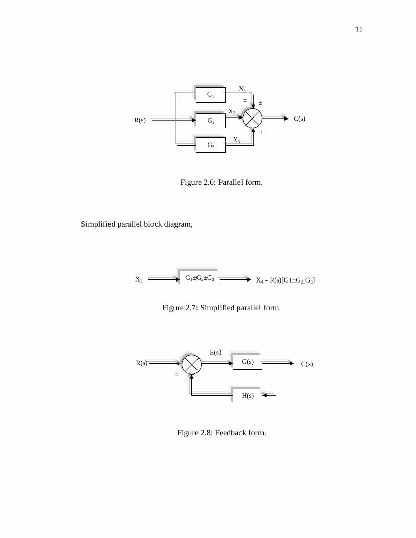
Figure 2.6: Parallel form.
Simplified parallel block diagram,
Figure 2.7: Simplified parallel form.
Figure 2.8: Feedback form.
±
± ±
X2
X3
X1 G1
R(s) G2
G3
C(s)
G1±G2±G3 X1 X4 = R(s)[G1±G2±G3]
±
R(s) G(s)
H(s)
E(s)
C(s)
12
Simplified feedback block diagram,
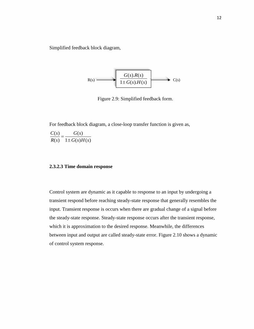
Figure 2.9: Simplified feedback form.
For feedback block diagram, a close-loop transfer function is given as,
( ) ( )
( ) 1 ( ) ( )
C s G s
R s G s H s
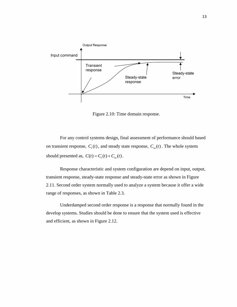
2.3.2.3 Time domain response
Control system are dynamic as it capable to response to an input by undergoing a
transient respond before reaching steady-state response that generally resembles the
input. Transient response is occurs when there are gradual change of a signal before
the steady-state response. Steady-state response occurs after the transient response,
which it is approximation to the desired response. Meanwhile, the differences
between input and output are called steady-state error. Figure 2.10 shows a dynamic
of control system response.
C(s) R(s) ( ). ( )
1 ( ). ( )
G s R s
G s H s
13
Figure 2.10: Time domain response.
For any control systems design, final assessment of performance should based
on transient response, ( )tC t , and steady state response, ( )ssC t . The whole system
should presented as, ( ) ( ) ( )t ssC t C t C t .
Response characteristic and system configuration are depend on input, output,
transient response, steady-state response and steady-state error as shown in Figure
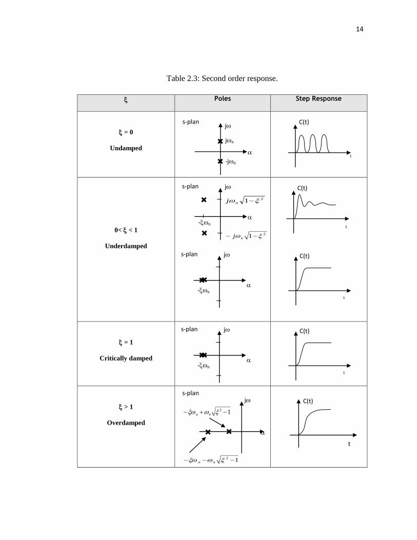
2.11. Second order system normally used to analyze a system because it offer a wide
range of responses, as shown in Table 2.3.
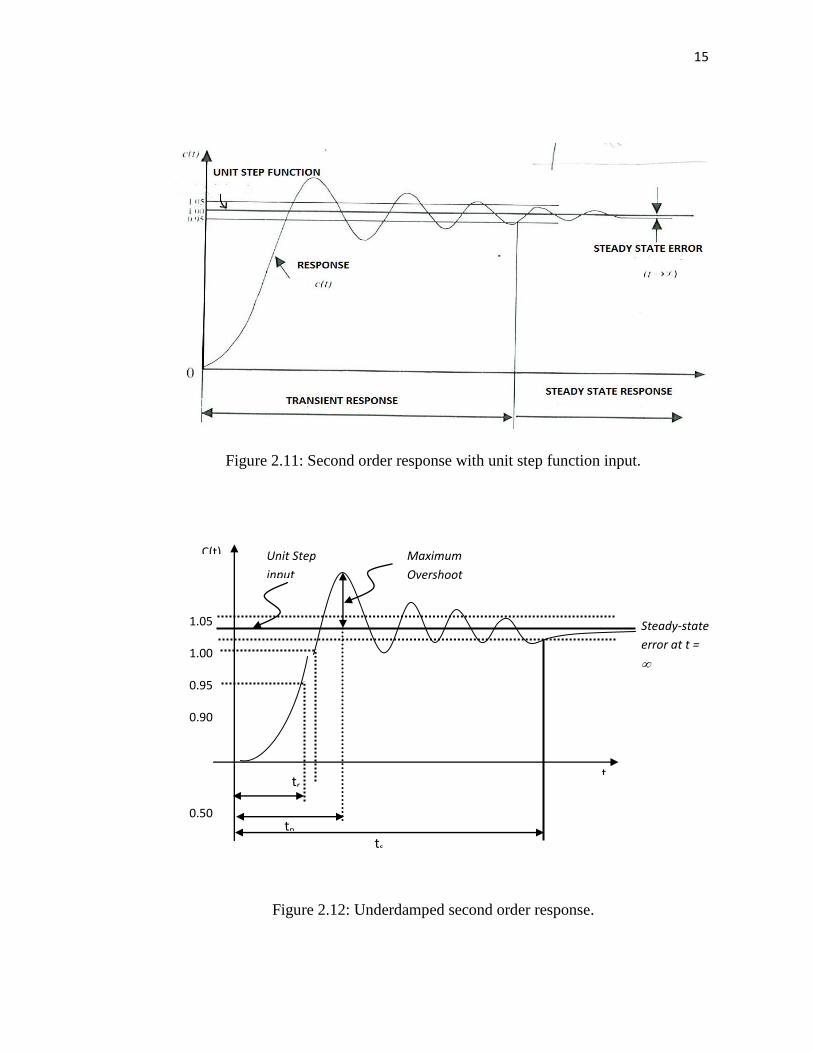
Underdamped second order response is a response that normally found in the
develop systems. Studies should be done to ensure that the system used is effective
and efficient, as shown in Figure 2.12.
14
Table 2.3: Second order response.
Poles Step Response
= 0
Undamped
0< < 1
Underdamped
= 1
Critically damped
> 1
Overdamped
j
jn
-jn
s-plan
t
C(t)
s-plan
j
12 nn
12 nn
t
C(t)
s-plan
j
-n
C(t)
t
s-plan
j
21 nj
21 nj
-n
C(t)
t
s-plan
j
-n
C(t)
t
15
Figure 2.11: Second order response with unit step function input.
Figure 2.12: Underdamped second order response.
1.05
1.00
0.95
0.90
0.50
0.10
Maximum
Overshoot
tr
tp
ts
Unit Step
input
Steady-state
error at t =
t =
C(t)
t
16
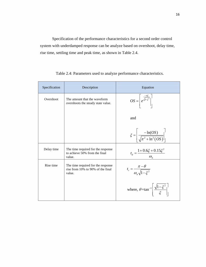
Specification of the performance characteristics for a second order control
system with underdamped response can be analyze based on overshoot, delay time,
rise time, settling time and peak time, as shown in Table 2.4.
Table 2.4: Parameters used to analyze performance characteristics.
Specification
Description
Equation
Overshoot
The amount that the waveform
overshoots the steady state value.
21
2 2
and
ln( )
ln
OS e
OS
OS
Delay time
The time required for the response
to achieve 50% from the final
value.
21 0.6 0.15
d
n
t
Rise time
The time required for the response
rise from 10% to 90% of the final
value.
2
21
1
1where, =tan
r
n
t

17
Table 2.4 (Continued)
Settling time
The time required for the
transient’s damped oscillations
to reach and stay 2% of the
steady state value.
4 (for 2%)
and
3 (for 4%)
s
n
s
n
t
t
Peak time
The time required to reach the
first or maximum peak.
21p
n
t
2.4 Converters
Converters serve as an interface between the source and load (Nise N. S., 2000) as
shown in Figure 2.13. It convert one type or level of a voltage or current waveform to
another and classified by the relationship between input signal and output signal as
shown in Table 2.5.
Figure 2.13: Basic converter system.
Source
Converter Load
Input Output
18
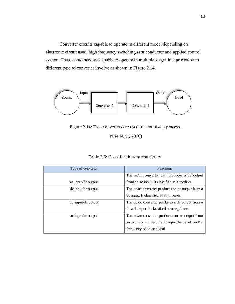
Converter circuits capable to operate in different mode, depending on
electronic circuit used, high frequency switching semiconductor and applied control
system. Thus, converters are capable to operate in multiple stages in a process with
different type of converter involve as shown in Figure 2.14.
Figure 2.14: Two converters are used in a multistep process.
(Nise N. S., 2000)
Table 2.5: Classifications of converters.
Type of converter Functions
ac input/dc output
The ac/dc converter that produces a dc output
from an ac input. It classified as a rectifier.
dc input/ac output
The dc/ac converter produces an ac output from a
dc input. It classified as an inverter.
dc input/dc output
The dc/dc converter produces a dc output from a
dc a dc input. It classified as a regulator.
ac input/ac output The ac/ac converter produces an ac output from
an ac input. Used to change the level and/or
frequency of an ac signal.
Output Input
Source Load
Converter 1
Converter 1
19
2.5 DC-DC converter
2.5.1 General overview of DC-DC converter
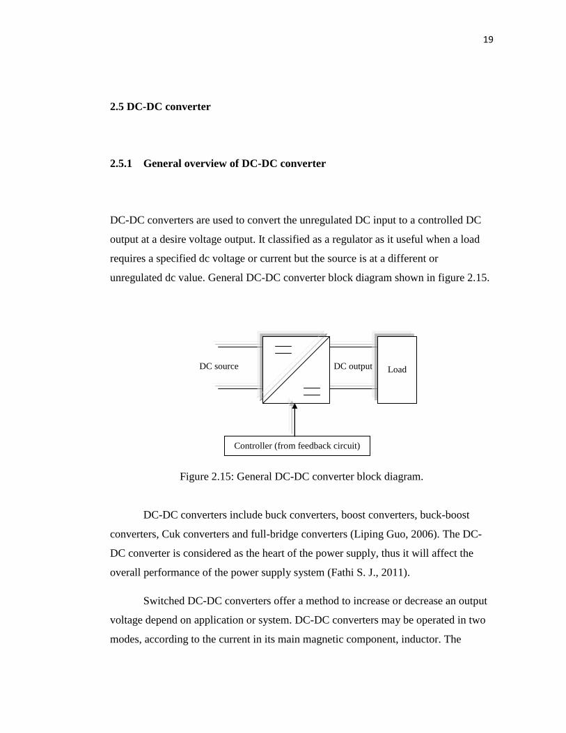
DC-DC converters are used to convert the unregulated DC input to a controlled DC
output at a desire voltage output. It classified as a regulator as it useful when a load
requires a specified dc voltage or current but the source is at a different or
unregulated dc value. General DC-DC converter block diagram shown in figure 2.15.
Figure 2.15: General DC-DC converter block diagram.
DC-DC converters include buck converters, boost converters, buck-boost
converters, Cuk converters and full-bridge converters (Liping Guo, 2006). The DC-
DC converter is considered as the heart of the power supply, thus it will affect the
overall performance of the power supply system (Fathi S. J., 2011).
Switched DC-DC converters offer a method to increase or decrease an output
voltage depend on application or system. DC-DC converters may be operated in two
modes, according to the current in its main magnetic component, inductor. The
DC output
DC source
Controller (from feedback circuit)
Load
20
current fluctuates but never goes down to zero is called Continuous Conduction Mode
(CCM) and Discontinuous Conduction Mode (DCM) occur when the current
fluctuates during the cycle, going down to zero at or before the end of each cycle.
Energy is periodically stored into and released from a magnetic field in an
inductor. Usually, this is applied to control the output voltage so that the output
voltage remains constant even though input voltages keep changing. There are two
general categories of DC-DC converters that is non-isolated DC-DC converter (Buck,
Boost, Buck-Boost) and isolated DC-DC converter (Flyback, Forward, Push-Pull,
Full-Bridge, Half-Bridge).
Non-isolated DC-DC converter were used when the input to these converters
is often an unregulated DC voltage, which is obtained by rectifying the line voltage,
and therefore it will fluctuate due to changes in the line voltage magnitude. Switched-
mode DC-DC converters are used to convert the unregulated DC input to a controlled
DC output at a desired voltage level (Emadi, A. et al., 2009).
Isolated DC-DC converter, full-bridge converter and half-bridge converter are
derived from the step-down converter. Flyback converters are derived from the buck-
boost converters. Forward converters and push-pull converters are derived from the
step-down converters with isolation.
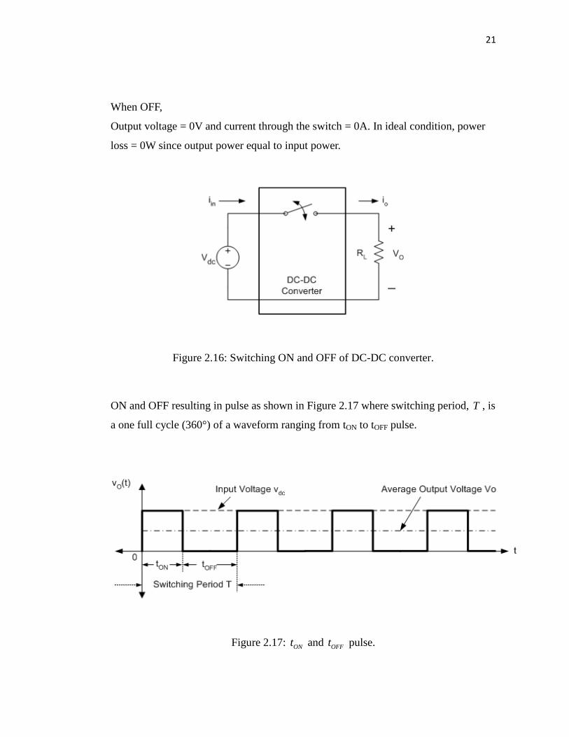
2.5.2 DC-DC converter switching
There are two switching condition that need to be applied, that is when ON and OFF
as shown in figure 2.16.
When ON,
Output voltage is the same as the input voltage and the voltage across the switch is
0V.
21
When OFF,
Output voltage = 0V and current through the switch = 0A. In ideal condition, power
loss = 0W since output power equal to input power.
Figure 2.16: Switching ON and OFF of DC-DC converter.
ON and OFF resulting in pulse as shown in Figure 2.17 where switching period, T , is
a one full cycle (360°) of a waveform ranging from tON to tOFF pulse.
Figure 2.17: ONt and OFFt pulse.

22
Thus, duty cycle, D, which depends on tON and range of duty cycle is
0 1D . If switching frequency, sf , is given,
Average DC output voltage,
There are two modes of operation in DC-DC converters based on inductor current, iL,
i) Continuous Conduction Mode (CCM), when 0Li .
ii) Discontinuous Conduction Mode (DCM) when iL goes to 0 and stays at 0 for
some time.
Figure 2.18: Continuous Conduction Mode.
son
on
offon
on ftT
t
tt
tD
(2.2)
( )0
0 0
1 1T DT
o i iV v t dt V dt V DT T
= = =ò ò (2.3)
23
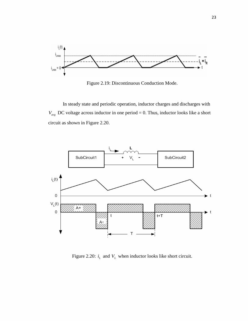
Figure 2.19: Discontinuous Conduction Mode.
In steady state and periodic operation, inductor charges and discharges with
avgV DC voltage across inductor in one period = 0. Thus, inductor looks like a short
circuit as shown in Figure 2.20.
Figure 2.20: Li and LV when inductor looks like short circuit.
24
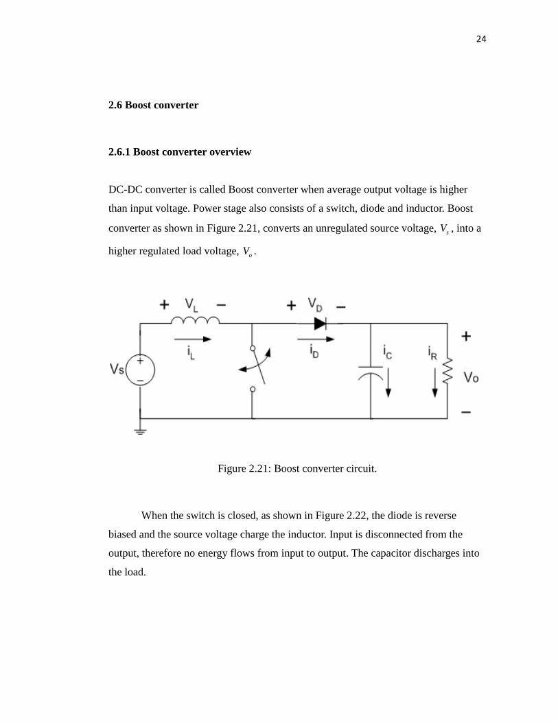
2.6 Boost converter
2.6.1 Boost converter overview
DC-DC converter is called Boost converter when average output voltage is higher
than input voltage. Power stage also consists of a switch, diode and inductor. Boost
converter as shown in Figure 2.21, converts an unregulated source voltage, sV , into a
higher regulated load voltage, oV .
Figure 2.21: Boost converter circuit.
When the switch is closed, as shown in Figure 2.22, the diode is reverse
biased and the source voltage charge the inductor. Input is disconnected from the
output, therefore no energy flows from input to output. The capacitor discharges into
the load.
73
REFERENCES
Emadi, A. Alireza Kaligh, Zhong nie, Young Joo Lee (2009). Integrated Power
Electronic Converters and Digital Control. CRC Press.
Fathi S. J. (2011). Development of a DC-DC Buck Boost Converter using Fuzzy Logic
Control. Universiti Tun Hussein Onn Malaysia. Master Thesis.
Feng, Q., Hung J. Y., Nelms R. M. (2003). Digital Control of a Boost Converter using
Posicast. IEEE. pp. 990-995.
Feng, Q., Hung, J. Y., Nelms, R. M. The Application of Posicast Control to DC-DC
Converters. Energy Conversion Engineering Conference. July 29 – 31. 37th
Intersociety. 2004. pp. 698 – 703.
Guo, Liping. (2006). Design and Implementation of Digital Controllers for Buck and
Boost Converters Using Linear and Nonlinear Control Method. Auburn
University. PhD Thesis.
Hart D. W. (2011). Power Electronics. New York: McGraw Hill.
Hasaneen, B. M., Elbaset Mohammed A. A. Design and Simulation of DC/DC Boost
Converter. Power System Conference. Mac 12 -15. 12th
International Middle-
East. 2008. pp. 335 – 340.
Jamaluddin, H., Yaacob, M. S., Ahmad, R. (2011). Introduction to Control
Engineering. UTM.
Hung, J. Y. (2007). Posicast Control Past and Present. IEEE Multidiciplinary
Engineering Education Magazine, 2(1), pp. 7 – 11.
74
Jang, Y., Jovanovic, M. M. (2002). A New, Soft-Switched, High-Power-Factor Boost
Converter with IGBTs. IEEE Transactions on Power Electronics, 17(4), pp.
469 – 476.
Kalatar, M. & Mousavi, S. M. (2010). Posicast Control within Feedback Structure for
a DC-DC Single Ended Primary Induction Converter in Renewable Energy
Applications. Elsevier. pp. 3110-3114.
Krauter, S. C. W. (2006). Solar Electric Power Generation – Photovoltaic Energy
Systems. Netherlands: Springer.
Kumar, K. R., Jeevananthan, S. (2011). Design of a Hybrid Posicast Control for a
DC-DC Boost Converter Operated in Continuous Conduction Mode.
Proceeding of ICETECT 2011, pp. 240 - 248.
Nise N. S. (2000). Control Systems Engineering Third Edition. New York: John
Wiley & Sons.
Salam, A. A., Mohamed A., Hannan M. A. (2009). Improved Control Strategy for
Fuel Cell and Photovoltaic Inverters in a Microgrid. WSEAS Transactions on
Power Systems. 4(10). pp. 331-340.
Thanakodi, S. (2009). Modeling and Simulation of Grid Connected Photovoltaic
System using MATLAB / SIMULINK. Universiti Teknologi Malaysia. Master
Thesis.
Xu, Quansheng (2005). Control System Study On PWM Boost DC-DC Converter In
CCM. Dalhousie University. Master Thesis.
Recommended


![Vol. 2, Issue 9, September 2013 DESIGN OF DC-DC BOOST ... · DESIGN OF DC-DC BOOST CONVERTER WITH THERMOELECTRIC POWER SOURCE ... [2-4].In this research, DC-DC boost converter is](https://img.dokumen.tips/doc/110x75/5aec36db7f8b9ae5318ea3af/vol-2-issue-9-september-2013-design-of-dc-dc-boost-of-dc-dc-boost-converter.jpg)