Paper No. 2-63 1
THISSAVROS HYDROPOWER PLANT MANAGING GEOTECHNICAL PROBLEMS IN THE CONSTRUCTION
K. Anastassopoulos E. Hoek V. Milligan W. Riemer Public Power Corporation Consultant Consultant Consultant Athens, Greece North Vancouver, Canada Oakville, Canada Ehner, Luxemburg
ABSTRACT The Thissavros hydropower and pumped storage project on the Nestos river in northern Greece involved construction of a 172 m high rockfill dam and an underground power house with 300 MW installed capacity. Bedrock at the site consists of gneiss with complex geological structure and complicated hydrogeological conditions. On the right abutment, the dam partially rests on a large landslide and the toe of another large landslide extends into the plunge pool from the left bank. Initial excavations activated the dormant slides. Unloading, buttressing and drainage successfully stabilized the landslides. Core material for the dam is a silty sand and required special precautions in design and construction. Starting with an extremely rapid reservoir filling the dam has performed highly satisfactorily. The power house had to be excavated in a relatively unfavorable geological orientation but application of structural discontinuity analysis avoided wedge failures.. INTRODUCTION The Thissavros dam is located on the Nestos river in the northeast of Greece, not far from the border to Bulgaria. The rugged mountain ranges were difficult for access and were sparsely populated. The latter condition favored the development of large hydroprojects. The Public Power Corporation of Greece initiated studies of the Nestos development some 40 years ago and has meanwhile completed also the second stage of the hydropower cascade, the 95 m high Platanovryssi RCC dam. Construction of the Thissavros dam started in 1986 and reservoir filling commenced in September 1996. During the implementation of the project, the following major problems confronted the designers and contractors:
• Design of a very high embankment dam with locally available material, coping with steep valley walls and partially poor and potentially unstable foundation
• Stabilization of two large landslides. The treatment of the landslides demanded adjustments in the project design and became time consuming.
• Construction of a large power cavern in rock with relatively adversely oriented discontinuities.
The Public Power Corporation had assigned a large team of geotechnical specialists and geologists to the project that developed solutions which continue to give very satisfactory performance.
Krapp and Pantzartzís (1989) had reported on the geological aspects of the project study and the early stages of construction. The current paper summarizes the measures adopted to cope with geotechnical problems of the site, the experience gained during completion and the recorded performance of the operating of the project. THE PROJECT The main purpose of the Thissavros project is the production of hydropower. The option to run the plant also as pumped storage enhances its value for the Greek power system. Moreover, downstream users benefit from better regulated run-off. The main components of the Thissavros scheme are:
• Rockfill dam with central clay core. Height above core foundation 172 m (crest elevation 390 m.a.s..l.), crest length 480 m, volume 13 million m³
• Gated spillway for a 7500 m³/s design flood. A tailwater dam creates a plunge pool to avoid scour from the spillway jet
• Underground Powerhouse, dimensions 22 m (width) x 42 m (height) x 100 m (length), with 3 X 100 MW installed capacity (Francis reversible pump - turbines).
Paper No. 2-63 2
GEOLOGICAL SETTING Dam and reservoir are located in metamorphic rocks of the pre-alpidic Rila-Rhodope Massif. The sequence consists of gneisses, schists and marbles. The age is not definitely established (Dercourt et al., 1980) but is considered to be pre-mesozoic (Jacobshagen, 1982). The Seismotectonic Map of Greece shows a series of east-west
directed normal faults crossing the massif. On the Bulgarian side, the tectonic features along the west flank of the massif are particularly prominent (Shanov et al., 1992) and are a source of seismic activity. One epicenter of a shock exceeding magnitude 7.5 is marked inside the Greek part of the massif. Gneiss, partially schistose, granitic gneiss and layers of mica schist are the main components of the bedrock at the dam site. There are local intercalations of pegmatite veins and amphibolite.
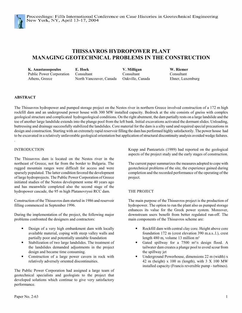
Figure 1. Dam site and landslides. Heavy lines mark faults. Coordinate grid on 200 m spacing
Paper No. 2-63 3
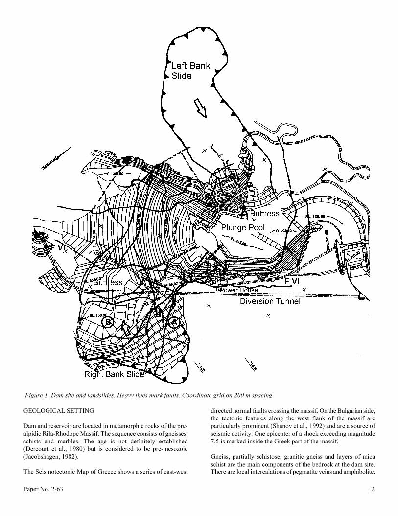
Foliation at the dam site trends almost perpendicularly to the valley and dips downstream at 40° to 60°. Additionally, there are two principal sets of subvertical joints, directed roughly parallel and perpendicular to the valley walls, respectively. Although some faults and shears traverse the rock, surface excavation in sound rock normally met with favorable conditions. However, excavations also revealed elements of critical significance for the performance of the slopes at the dam site. These were low angle thrust faults, dipping 15° to 35°, found to continue extensively over the site and the slopes. Thick clay gouge developed along these faults acted as hydrogeological barriers in the rock mass, locally resulting in adverse hydraulic thrusts in the slopes. Owing to low shear strength on these faults, combined with the groundwater loads, major stability problems developed during the early construction phase of the project. Principal faults and shears are traced in Fig. 1; Fig. 2. illustrates the orientation of the various fault systems in the rock mass.
THE LANDSLIDES AT THE DAM SITE Based on morphological criteria, project geologists initially assumed the possible existence of several large, dormant landslides at the dam site, but the significance of these slides for the project and even their mere existence was debated by specialist advisors. There are several case histories of similar controversies with regard to old landslides and these case histories demonstrate the difficulties in the identification and the risk assessment of such geotechnical hazards. At the Thissavros site, detailed investigations as well as notable slope movements, initiated in the course of the construction activities, eventually established the scale of the hazard. Two significant areas of instability developed at the site (see Fig. 1); these are discussed further below.
Right Bank Slide The slide is about 500 m wide and affects the slope below el. 520m. The volume of the slide amounts to about 7 million m³, divided into two activated segments. Segment A, along the east (downstream flank) contains highly fractured and locally decomposed gneiss. The front of the slide mass follows a thrust fault, designated as F VI which is characterized by 4 m clay gouge with a conspicuous green color. It is, therefore, also referred to as the "Green Fault". It strikes southwest-northeast and dips flatly southeast into the slope (dip azimuth/dip = 120-160/20-30°). Movement concentrates in a 5 cm thick clay seam that shows striation directed west (275-282°). The fault crosses the core trench on the right abutment 50 m below the crest near el. 340 m. In conjunction with other faults with dip components towards the valley, it generates a wedge-shaped mobile mass. Segment B, to the west and partially resting on the Segment A rock, contains chaotic debris of blocks and decomposed rock. Stripping of the foundation and cuts for access roads in 1986 triggered local slips in the unstable mass. Therefore, a monitoring system combining borehole inclinometers, piezometers and survey monuments was installed with the multiple purpose of ensuring safety of construction work, providing geotechnical information and assessing the efficiency of remedial measures. When fault F VI was exposed in the core trench and the shell foundation on the right abutment, displacements of up to 7 mm/day were measured on this fault. Towards the end of 1988 the displacements totaled 50 cm in Segment A and 150 cm in the more actively displacing Segment B. Within the segments, most active displacements concentrated in the upstream part of A and the upper reach of B. Thus, there were also internal deformations of the slide masses.
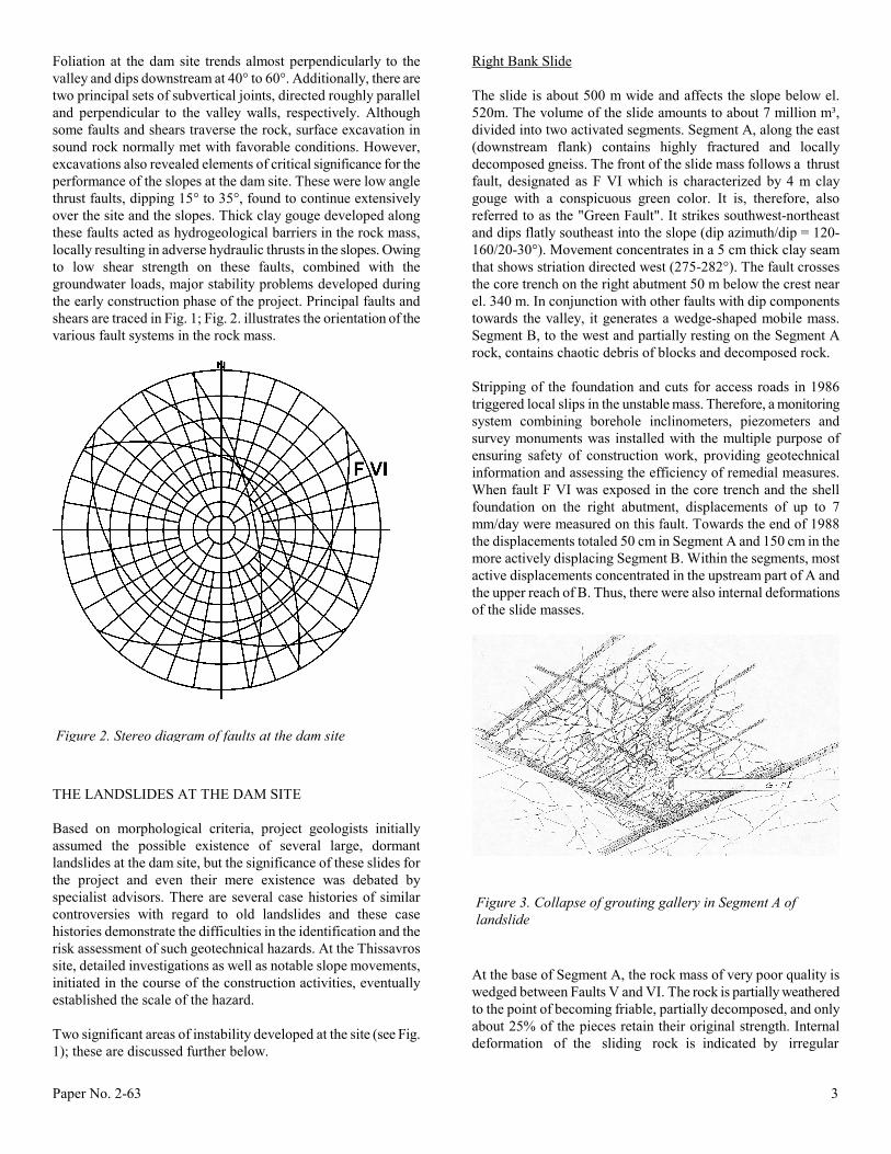
At the base of Segment A, the rock mass of very poor quality is wedged between Faults V and VI. The rock is partially weathered to the point of becoming friable, partially decomposed, and only about 25% of the pieces retain their original strength. Internal deformation of the sliding rock is indicated by irregular
Figure 2. Stereo diagram of faults at the dam site
Figure 3. Collapse of grouting gallery in Segment A of landslide
Paper No. 2-63 4
orientation of the foliation planes. When the lower right-bank grouting tunnel entered this zone, a major collapse occurred that also affected the intermediate grouting tunnel, located 40 m higher in the slope (Fig. 3). In consequence of this collapse, the material in the center of the wedge deteriorated even more. The poor quality rock near the center and base of the sliding wedge did not permit systematic Lugeon testing but the limited number of tests gave a notable permeability for the slide mass, on the order of 10-5 m/s, but lower than for the adjacent in-situ rock. According to grain size distribution, the permeability of the soils produced by alteration of the gneiss was estimated to range from 10-4 to 10-3 m/s but presumably core drilling did not recover representative samples from the soils. Fines appear to have been lost. Remedial measures for the right bank included major excavation and stripping to unload the head of the unstable mass, toe buttressing and drainage. Unloading the head of the landslide in Segment A by excavation of 1.65 million m³, combined with subhorizontal drain holes that dropped the groundwater levels by 10m, stopped the initial movements in 1988. However, preparatory excavation for the power intake caused the slide to accelerate again to a rate of 17 mm/day in early 1989. This time, 0.9 million m³ were removed at the head of Segment B, and a toe buttress placed between El. 280 and 420 m definitely stopped the displacements of the slide mass. The final volume of excavation for unloading arrived at 2.6 million m³. Back analysis, carried out in the early stages of the project, estimated a friction angle of 22° (Krapp et al., 1989). However, laboratory tests made at a later stage on samples taken from the "Green Fault" found an angle of residual friction of 12 to 13°. The deteriorated material in Segment B is practically homogeneous in hydrogeological aspects, but the faults and shears intricately compartmentalize the Segment A and the in-situ rock beneath it. Therefore, particular attention was given to the hydrogeological treatment of Segment A. The final design provides a combination of grout curtain and drainage system to draw down the groundwater levels under the head of the landslide, to increase the effective shear resistance within the slope and, at the same time, to create a hydraulic thrust against the slope. About 15,000 m² of the grout curtain pass through Segments A and B of the landslide. Grouting and drainage galleries are arranged at three levels in the right abutment, approximately at Elevations 250 m, 300 m and 350 m. The highest reach of the curtain was drilled directly from a bench at the surface at El. 390 m. From the surface down to sound rock below Fault F VI the curtain has three rows. Because of the poor quality of the rock, there were doubts that a conventional grout curtain would suffice to reduce the permeability and prevent erosion induced by seepage into the drainage galleries. Alteration of the gneiss in the slide mass had produced a sandy residue with a high silt content that would not be penetrated by conventional cement slurries. Therefore, the possibilities were studied to use ultra-fine cement, chemical grout or jet grouting on the central row of the curtain. Nevertheless, extensive tests demonstrated that conventional grouting with cement slurries achieved satisfactory results, essentially by cracking and compacting the
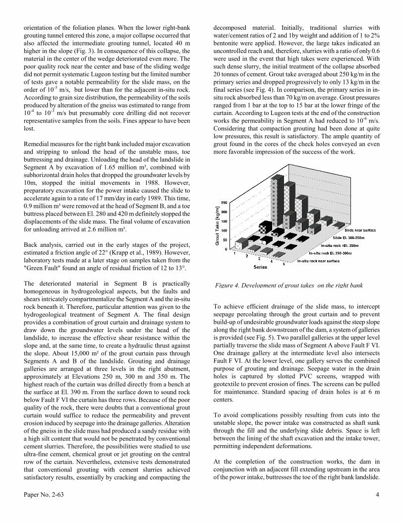
decomposed material. Initially, traditional slurries with water/cement ratios of 2 and 1by weight and addition of 1 to 2% bentonite were applied. However, the large takes indicated an uncontrolled reach and, therefore, slurries with a ratio of only 0.6 were used in the event that high takes were experienced. With such dense slurry, the initial treatment of the collapse absorbed 20 tonnes of cement. Grout take averaged about 250 kg/m in the primary series and dropped progressively to only 13 kg/m in the final series (see Fig. 4). In comparison, the primary series in in-situ rock absorbed less than 70 kg/m on average. Grout pressures ranged from 1 bar at the top to 15 bar at the lower fringe of the curtain. According to Lugeon tests at the end of the construction works the permeability in Segment A had reduced to 10-6 m/s. Considering that compaction grouting had been done at quite low pressures, this result is satisfactory. The ample quantity of grout found in the cores of the check holes conveyed an even more favorable impression of the success of the work.
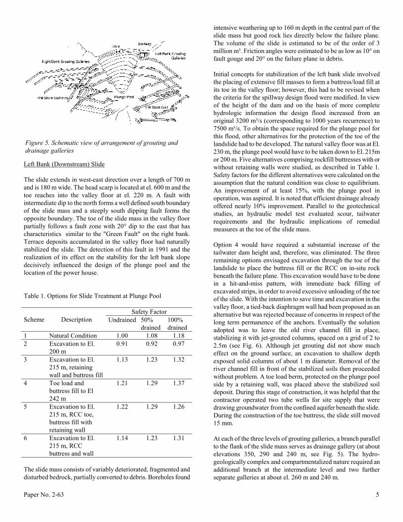
To achieve efficient drainage of the slide mass, to intercept seepage percolating through the grout curtain and to prevent build-up of undesirable groundwater loads against the steep slope along the right bank downstream of the dam, a system of galleries is provided (see Fig. 5). Two parallel galleries at the upper level partially traverse the slide mass of Segment A above Fault F VI. One drainage gallery at the intermediate level also intersects Fault F VI. At the lower level, one gallery serves the combined purpose of grouting and drainage. Seepage water in the drain holes is captured by slotted PVC screens, wrapped with geotextile to prevent erosion of fines. The screens can be pulled for maintenance. Standard spacing of drain holes is at 6 m centers. To avoid complications possibly resulting from cuts into the unstable slope, the power intake was constructed as shaft sunk through the fill and the underlying slide debris. Space is left between the lining of the shaft excavation and the intake tower, permitting independent deformations. At the completion of the construction works, the dam in conjunction with an adjacent fill extending upstream in the area of the power intake, buttresses the toe of the right bank landslide.
Figure 4. Development of grout takes on the right bank
Paper No. 2-63 5
Left Bank (Downstream) Slide The slide extends in west-east direction over a length of 700 m and is 180 m wide. The head scarp is located at el. 600 m and the toe reaches into the valley floor at el. 220 m. A fault with intermediate dip to the north forms a well defined south boundary of the slide mass and a steeply south dipping fault forms the opposite boundary. The toe of the slide mass in the valley floor partially follows a fault zone with 20° dip to the east that has characteristics similar to the "Green Fault" on the right bank. Terrace deposits accumulated in the valley floor had naturally stabilized the slide. The detection of this fault in 1991 and the realization of its effect on the stability for the left bank slope decisively influenced the design of the plunge pool and the location of the power house. Table 1. Options for Slide Treatment at Plunge Pool
Safety Factor
Scheme
Description Undrained 50% drained
100% drained
1 Natural Condition 1.00 1.08 1.18 2 Excavation to El.
200 m 0.91 0.92 0.97
3 Excavation to El. 215 m, retaining wall and buttress fill
1.13 1.23 1.32
4 Toe load and buttress fill to El 242 m
1.21 1.29 1.37
5 Excavation to El. 215 m, RCC toe, buttress fill with retaining wall
1.22 1.29 1.26
6 Excavation to El. 215 m, RCC buttress and wall
1.14 1.23 1.31
The slide mass consists of variably deteriorated, fragmented and disturbed bedrock, partially converted to debris. Boreholes found
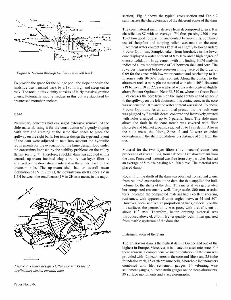
intensive weathering up to 160 m depth in the central part of the slide mass but good rock lies directly below the failure plane. The volume of the slide is estimated to be of the order of 3 million m³. Friction angles were estimated to be as low as 10° on fault gouge and 20° on the failure plane in debris. Initial concepts for stabilization of the left bank slide involved the placing of extensive fill masses to form a buttress/load fill at its toe in the valley floor; however, this had to be revised when the criteria for the spillway design flood were modified. In view of the height of the dam and on the basis of more complete hydrologic information the design flood increased from an original 3200 m³/s (corresponding to 1000 years recurrence) to 7500 m³/s. To obtain the space required for the plunge pool for this flood, other alternatives for the protection of the toe of the landslide had to be developed. The natural valley floor was at El. 230 m, the plunge pool would have to be taken down to El. 215m or 200 m. Five alternatives comprising rockfill buttresses with or without retaining walls were studied, as described in Table 1. Safety factors for the different alternatives were calculated on the assumption that the natural condition was close to equilibrium. An improvement of at least 15%, with the plunge pool in operation, was aspired. It is noted that efficient drainage already offered nearly 10% improvement. Parallel to the geotechnical studies, an hydraulic model test evaluated scour, tailwater requirements and the hydraulic implications of remedial measures at the toe of the slide mass. Option 4 would have required a substantial increase of the tailwater dam height and, therefore, was eliminated. The three remaining options envisaged excavation through the toe of the landslide to place the buttress fill or the RCC on in-situ rock beneath the failure plane. This excavation would have to be done in a hit-and-miss pattern, with immediate back filling of excavated strips, in order to avoid excessive unloading of the toe of the slide. With the intention to save time and excavation in the valley floor, a tied-back diaphragm wall had been proposed as an alternative but was rejected because of concerns in respect of the long term permanence of the anchors. Eventually the solution adopted was to leave the old river channel fill in place, stabilizing it with jet-grouted columns, spaced on a grid of 2 to 2.5m (see Fig. 6). Although jet grouting did not show much effect on the ground surface, an excavation to shallow depth exposed solid columns of about 1 m diameter. Removal of the river channel fill in front of the stabilized soils then proceeded without problem. A toe load berm, protected on the plunge pool side by a retaining wall, was placed above the stabilized soil deposit. During this stage of construction, it was helpful that the contractor operated two tube wells for site supply that were drawing groundwater from the confined aquifer beneath the slide. During the construction of the toe buttress, the slide still moved 15 mm. At each of the three levels of grouting galleries, a branch parallel to the flank of the slide mass serves as drainage gallery (at about elevations 350, 290 and 240 m, see Fig. 5). The hydro-geologically complex and compartmentalized nature required an additional branch at the intermediate level and two further separate galleries at about el. 260 m and 240 m.
Figure 5. Schematic view of arrangement of grouting and drainage galleries
Paper No. 2-63 6
Figure 7. Tender design. Dotted line marks toe of preliminary design earthfill dam
To provide the space for the plunge pool, the slope opposite the landslide was trimmed back by a 180 m high and steep cut in rock. The rock in this vicinity consists of fairly massive granitic gneiss. Potentially mobile wedges in this cut are stabilized by prestressed monobar anchors. DAM Preliminary concepts had envisaged extensive removal of the slide material, using it for the construction of a gently sloping earth dam and creating at the same time space to place the spillway on the right bank. For tender design the type and layout of the dam were adjusted to take into account the hydraulic requirements for the evacuation of the large design flood under the constraints imposed by the stability problems on the valley flanks (see Fig. 7). Therefore, a rockfill dam was adopted with a central, upstream inclined clay core. A two-layer filter is arranged on the downstream side and in the upper reach on the upstream side. The upstream shell has an overall mean inclination of 1V in 2.25 H, the downstream shell slopes 1V in 1.5H between the road berms (1V in 2H as a mean, in the major
section). Fig. 8 shows the typical cross section and Table 2 summarizes the characteristics of the different zones of the dam. The core material mainly derives from decomposed gneiss. It is classified as SC with on average 17% fines passing #200 sieve. To obtain good compaction and contact between lifts, combined use of sheepfoot and tamping rollers was made on the core. Placement water content was kept at or slightly below Standard Proctor Optimum. Samples taken from boreholes in the lower core displayed a water content of 8 to 10% and a high degree of overconsolidation. In agreement with this finding, FEM analysis indicated a low modulus ratio of 3:1 between shell and core. The ru values measured before reservoir filling were of the order of 0.09 for the zones with low water content and reached up to 0.4 in zones with 10-16% water content. Along the contact to the abutment rock, a more plastic material with about 40% fines and a PI between 18 an 22% was placed with a water content slightly above Proctor Optimum. Near El. 340 m, where the Green Fault F VI crosses the core trench on the right abutment and adjacent to the spillway on the left abutment, this contact zone in the core was widened to 10 m and the water content was raised 1% above Proctor Optimum. As an additional precaution, the fault zone was plugged by 7 m wide dental concrete and intensively grouted with holes arranged in up to 6 parallel lines. The slide mass above the fault in the core trench was covered with fiber shotcrete and blanket grouting reached up to 18 m depth. Also in the slide mass, the filters, Zones 2 and 3, were extended downstream in the shell foundation to a distance of 5 m from the toe. Material for the two–layer filters (fine – coarse) came from processing of river alluvia, from a deposit 3 km downstream from the dam. Processed material was free from clay particles, but had an average of 5 to 6% passing No. 200 sieve. The material was placed damp. Rockfill for the shells of the dam was obtained from sound gneiss from required excavation at the dam site that supplied the bulk volume for the shells of the dam. This material was gap graded but compacted reasonably well. Large scale, 800 mm, triaxial tests indicated the compacted material had excellent shearing resistance, with apparent friction angles between 44 and 50°. However, because of a high proportion of fines, especially on the lift surfaces the permeability was poor, with a coefficient of about 10-6 m/s. Therefore, better draining material was introduced above el. 340 m. Better quality rockfill was quarried from marble upstream of the dam site. Instrumentation of the Dam The Thissavros dam is the highest dam in Greece and one of the highest in Europe. Moreover, it is located in a seismic zone. For these reasons a comprehensive instrumentation of the dam was provided with 42 piezometers in the core and filters and 25 in the foundation rock, 15 earth pressure cells, 8 borehole inclinometers combined with Idel settlement gauges, 14 vibrating wire settlement gauges, 6 linear strain gauges on the steep abutments, 39 surface monuments and 8 accelerographs.
Figure 6. Section through toe buttress at left bank
Paper No. 2-63 7
Although precautions with the backfill of the inclinometer casing were taken, many casings buckled during construction so the inclinometer probe would not pass any more. While measurement of lateral deformations was inhibited, settlement readings were nevertheless still possible. In some instances aluminium casings corroded close to the water table and had to be replaced by PVC tubes.
The embankment was completed in 1994. Total settlements of the fill recorded until end of construction have been extremely small, ranging from about 1.2 to 1.5%. Horizontal displacements of about 30 cm were estimated from one inclinometer. In the end- of-construction analysis, linear-elastic and non-linear-elastic FEM modeling gave the best agreement with the recorded embankment strains, introducing a mean modulus of 60 to 80 MPa for the shells.
Vibrating wire settlement gauges did not work satisfactorily. It is believed that the settlements have cut the mercury tubes connecting the cells with the transducers, although these tubes had been placed with a generous slack. The earth pressure cells, on the other hand, worked well and revealed a pronounced
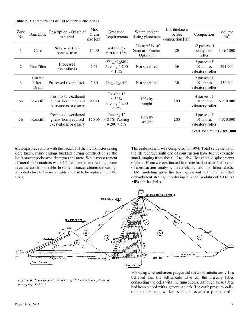
Table 2.. Characteristics of Fill Materials and Zones
Zone No Dam Zone Description - Origin of
material
Max Grain
size [cm]
Gradation Requirements
Water content during placement
Lift thickness before
compaction [cm] Compaction Volume
[m3]
1 Core Silty sand from borrow areas 15.00 # 4 > 60%
# 200 > 13%
-2% to +2% of Standard Proctor
Optimum 20
12 passes of sheepfoot
roller 1.467.000
2 Fine Filter Processed river alluvia 2.51
45%<#4<80% Passing # 200
< 10% Not specified 30
2 passes of 10 tonnes
vibratory roller 294.000
3 Coarse Filter - Drain
Processed river alluvia 7.60 2%<#4<44% Not specified 30 2 passes of 10 tonnes
vibratory roller 350.000
5a Rockfill Fresh to sl. weathered gneiss from required excavations or quarry
90.00
Passing 1'' < 30%
Passing # 200 < 5%
10% by weight 100
4 passes of 10 tonnes
vibratory roller 6.230.000
5b Rockfill Fresh to sl. weathered gneiss from required excavations or quarry
150.00 Passing 1''
< 30% Passing # 200 < 5%
10% by weight 200
4 passes of 10 tonnes
vibratory roller 4.550.000
Total Volume : 12.891.000
Figure 8. Typical sextion of rockfill dam. Description of zones see Table 2
Paper No. 2-63 8
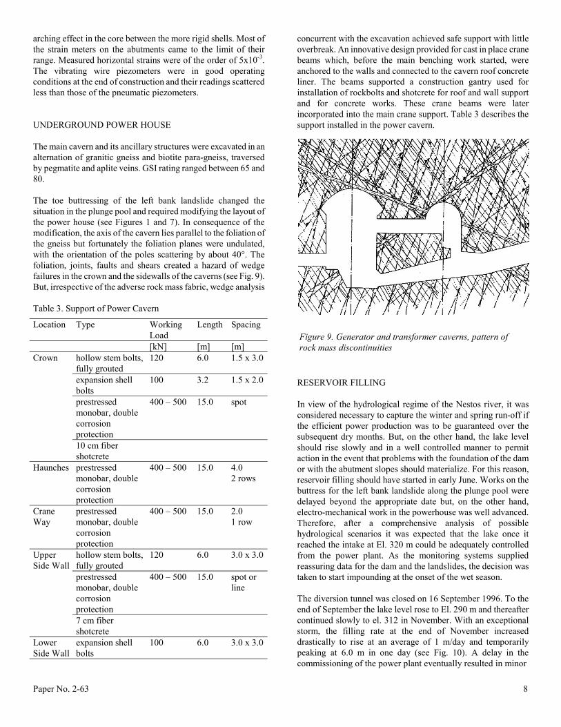
arching effect in the core between the more rigid shells. Most of the strain meters on the abutments came to the limit of their range. Measured horizontal strains were of the order of 5x10⁻³. The vibrating wire piezometers were in good operating conditions at the end of construction and their readings scattered less than those of the pneumatic piezometers. UNDERGROUND POWER HOUSE The main cavern and its ancillary structures were excavated in an alternation of granitic gneiss and biotite para-gneiss, traversed by pegmatite and aplite veins. GSI rating ranged between 65 and 80. The toe buttressing of the left bank landslide changed the situation in the plunge pool and required modifying the layout of the power house (see Figures 1 and 7). In consequence of the modification, the axis of the cavern lies parallel to the foliation of the gneiss but fortunately the foliation planes were undulated, with the orientation of the poles scattering by about 40°. The foliation, joints, faults and shears created a hazard of wedge failures in the crown and the sidewalls of the caverns (see Fig. 9). But, irrespective of the adverse rock mass fabric, wedge analysis Table 3. Support of Power Cavern
Location Type Working Load
Length Spacing
[kN] [m] [m] hollow stem bolts, fully grouted
120 6.0 1.5 x 3.0
expansion shell bolts
100 3.2 1.5 x 2.0
prestressed monobar, double corrosion protection
400 – 500 15.0 spot
Crown
10 cm fiber shotcrete
Haunches prestressed monobar, double corrosion protection
400 – 500 15.0 4.0 2 rows
Crane Way
prestressed monobar, double corrosion protection
400 – 500 15.0 2.0 1 row
hollow stem bolts, fully grouted
120 6.0 3.0 x 3.0
prestressed monobar, double corrosion protection
400 – 500 15.0 spot or line
Upper Side Wall
7 cm fiber shotcrete
Lower Side Wall
expansion shell bolts
100 6.0 3.0 x 3.0
concurrent with the excavation achieved safe support with little overbreak. An innovative design provided for cast in place crane beams which, before the main benching work started, were anchored to the walls and connected to the cavern roof concrete liner. The beams supported a construction gantry used for installation of rockbolts and shotcrete for roof and wall support and for concrete works. These crane beams were later incorporated into the main crane support. Table 3 describes the support installed in the power cavern.
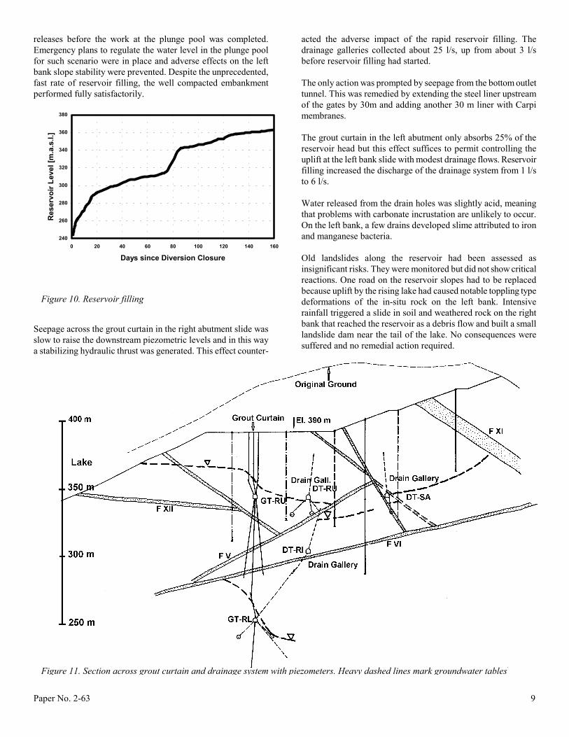
RESERVOIR FILLING In view of the hydrological regime of the Nestos river, it was considered necessary to capture the winter and spring run-off if the efficient power production was to be guaranteed over the subsequent dry months. But, on the other hand, the lake level should rise slowly and in a well controlled manner to permit action in the event that problems with the foundation of the dam or with the abutment slopes should materialize. For this reason, reservoir filling should have started in early June. Works on the buttress for the left bank landslide along the plunge pool were delayed beyond the appropriate date but, on the other hand, electro-mechanical work in the powerhouse was well advanced. Therefore, after a comprehensive analysis of possible hydrological scenarios it was expected that the lake once it reached the intake at El. 320 m could be adequately controlled from the power plant. As the monitoring systems supplied reassuring data for the dam and the landslides, the decision was taken to start impounding at the onset of the wet season. The diversion tunnel was closed on 16 September 1996. To the end of September the lake level rose to El. 290 m and thereafter continued slowly to el. 312 in November. With an exceptional storm, the filling rate at the end of November increased drastically to rise at an average of 1 m/day and temporarily peaking at 6.0 m in one day (see Fig. 10). A delay in the commissioning of the power plant eventually resulted in minor
Figure 9. Generator and transformer caverns, pattern of rock mass discontinuities
Paper No. 2-63 9
releases before the work at the plunge pool was completed. Emergency plans to regulate the water level in the plunge pool for such scenario were in place and adverse effects on the left bank slope stability were prevented. Despite the unprecedented, fast rate of reservoir filling, the well compacted embankment performed fully satisfactorily.
240
260
280
300
320
340
360
380
0 20 40 60 80 100 120 140 160
Days since Diversion Closure
Res
ervo
ir Le
vel [
m.a
.s.l.
]
Seepage across the grout curtain in the right abutment slide was slow to raise the downstream piezometric levels and in this way a stabilizing hydraulic thrust was generated. This effect counter-
acted the adverse impact of the rapid reservoir filling. The drainage galleries collected about 25 l/s, up from about 3 l/s before reservoir filling had started. The only action was prompted by seepage from the bottom outlet tunnel. This was remedied by extending the steel liner upstream of the gates by 30m and adding another 30 m liner with Carpi membranes. The grout curtain in the left abutment only absorbs 25% of the reservoir head but this effect suffices to permit controlling the uplift at the left bank slide with modest drainage flows. Reservoir filling increased the discharge of the drainage system from 1 l/s to 6 l/s. Water released from the drain holes was slightly acid, meaning that problems with carbonate incrustation are unlikely to occur. On the left bank, a few drains developed slime attributed to iron and manganese bacteria. Old landslides along the reservoir had been assessed as insignificant risks. They were monitored but did not show critical reactions. One road on the reservoir slopes had to be replaced because uplift by the rising lake had caused notable toppling type deformations of the in-situ rock on the left bank. Intensive rainfall triggered a slide in soil and weathered rock on the right bank that reached the reservoir as a debris flow and built a small landslide dam near the tail of the lake. No consequences were suffered and no remedial action required.
Figure 10. Reservoir filling
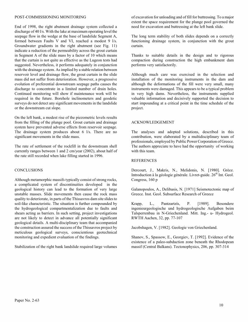
Figure 11. Section across grout curtain and drainage system with piezometers. Heavy dashed lines mark groundwater tables
Paper No. 2-63
10
POST-COMMISSIONING MONITORING End of 1998, the right abutment drainage system collected a discharge of 40 l/s. With the lake at maximum operating level the seepage flow in the wedge at the base of landslide Segment A, formed between Faults V and VI, reached a modest 9 l/s. Groundwater gradients in the right abutment (see Fig. 11) indicate a reduction of the permeability across the grout curtain in Segment A of the slide mass by a factor of 10 which means that the curtain is not quite as effective as the Lugeon tests had suggested. Nevertheless, it performs adequately in conjunction with the drainage system. As implied by a stable relation between reservoir level and drainage flow, the grout curtain in the slide mass did not suffer from deterioration. However, a progressive evolution of preferential downstream seepage paths causes the discharge to concentrate in a limited number of drain holes. Continued monitoring will show if maintenance work will be required in the future. Borehole inclinometers and geodetic surveys do not detect any significant movements in the landslide or the downstream cut slope. On the left bank, a modest rise of the piezometric levels results from the filling of the plunge pool. Grout curtain and drainage system have prevented adverse effects from reservoir seepage. The drainage system produces about 6 l/s. There are no significant movements in the slide mass. The rate of settlement of the rockfill in the downstream shell currently ranges between 1 and 2 cm/year (2002), about half of the rate still recorded when lake filling started in 1996. CONCLUSIONS Although metamorphic massifs typically consist of strong rocks, a complicated system of discontinuities developed in the geological history can lead to the formation of very large unstable masses. Slide movements then cause the rock mass quality to deteriorate, in parts of the Thissavros dam site slides to soil-like characteristic. The situation is further compounded by the hydrogeological compartmentalization due to faults and shears acting as barriers. In such setting, project investigations are not likely to detect in advance all potentially significant geological details. A multi-disciplinary team that accompanied the construction assured the success of the Thissavros project by meticulous geological surveys, conscientious geotechnical monitoring and expedient evaluation of the findings. Stabilization of the right bank landslide required large volumes
of excavation for unloading and of fill for buttressing. To a major extent the space requirement for the plunge pool governed the need for excavation and buttressing at the left bank slide. The long term stability of both slides depends on a correctly functioning drainage system, in conjunction with the grout curtain. Thanks to suitable details in the design and to rigorous compaction during construction the high embankment dam performs very satisfactorily. Although much care was exercised in the selection and installation of the monitoring instruments in the dam and although the deformations of the fill were very small, many instruments were damaged. This appears to be a typical problem in very high dams. Nevertheless, the instruments supplied valuable information and decisively supported the decision to start impounding at a critical point in the time schedule of the project. ACKNOWLEDGEMENT The analyses and adopted solutions, described in this contribution, were elaborated by a multidisciplinary team of professionals, employed by Public Power Corporation of Greece. The authors appreciate to have had the opportunity of working with this team. REFERENCES Dercourt, J., Makris, N., Melidonis, N. [1980]. Grèce. Introduction à la géologie générale. Livret-guide. 26th Int. Geol. Congress, 160 p Galanopoulos, A., Delibasis, N. [1971] Seismotectonic map of Greece. Inst. Geol. Subsurface Research of Greece Krapp, L., Pantzartzís, P. [1989]. Besondere ingenieurgeologische und hydrogeologische Aufgaben beim Talsperrenbau in N-Griechenland. Mitt. Ing.- u- Hydrogeol. RWTH Aachen, 32, pp. 77-107 Jacobshagen, V. [1982]. Geologie von Griechenland. Shanov, S., Spassow, E., Georgiev, T. [1992]. Evidence of the existence of a paleo-subduction zone beneath the Rhodopean massif (Central Balkans). Tectonophysics, 206, pp. 307-314
Recommended