PROGRAMMABLESCHOOL BELL
Project Design Presented to the Electrical / Electronics Engineering Department
Eastern Visavas State UniversityTacloban City
Presented By:Danika Jan P. BasadaJay Mark C. PacantaraJosiah Jay S.Samaniego
CHAPTER 1Introduction
Background of the study
The simple school bell system is going through a modern makeover. Schools are finding that the automatic school bell provides a better use of staff and student time. Some schools now prefer automatic school bell than manual operation of college bell because it creates a lot of disturbance caused by human error.
Statement of the problem The following are problem that our project seeks
to be resolved:
• School bell are inadequate due to the fact that they are too simple to manipulate by most users.
•Does not display the current time and outdated audible stimulation methods to warn the user
•Creates lot of disturbance caused by human error
•Hearing loss to those in the proximity caused by nearby proximity to the noisy bell.
Significance of the Study
The design would be beneficial to the following:
•Administration- The Administration would not worry of ringing the alarm every time or would not hire an operator to manually ring the bell since the School Bell will be programmed for it will work automatically.
• Students- The class schedule of the students will be followed accordingly since the School Bell Alarm will indicate the start and end of every class period.
• Instructor- The instructor’s schedule will also be followed since the instructor will be aware if the time for his/her class is not yet over or had passed, thus, the time intended for class hours will be maximized.
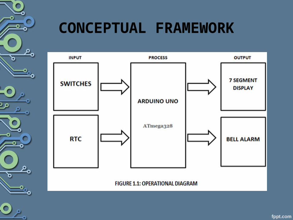
CONCEPTUAL FRAMEWORK

SCOPE AND DELIMITATION
Our design, having set the objectives would have several features:
SCOPE OF THE STUDY• It would be able to ring the bell at the exact time
as set by the user.• It displays Real time clock that keeps track of the
current time.• The sound of the alarm can be heard across the
room, and will ring for about 30 seconds.• This device can be turn off during weekends and
still the current time is stored on the RTC. Thus the current time will be displayed when the device is turned on.
• The time display is in 24 hour format.

However the following areas are the limitation of our design, most of which are not to be addressed due to limited resources.
• The school bell is limited to eight (8) programmable time.
• The design project will not be able to ring the bell if power failure occurs. The time will not be displayed either.
• This device will be destroyed in the presence of a liquid substance. Keep on a dry place.
Definition of TermsSchool Bell•- A school bell is a signal in a school that tells the students when it is time to go to class in the morning and when it is time to change classes during the day.RTC•- A clock that keeps track of the time even when the computer is turned off. Real-time clocks run on a special battery that is not connected to the normal power supply. In contrast, clocks that are not real-time do not function when the computer is off.
Arduino UNO•- The Arduino Uno is a microcontroller board based on the ATmega328 . It has 14 digital input/output pins (of which 6 can be used as PWM outputs), 6 analog inputs, a 16 MHz ceramic resonator, a USB connection, a power jack, an ICSP header, and a reset button. It contains everything needed to support the microcontroller; simply connect it to a computer with a USB cable or power it with a AC-to-DC adapter or battery to get started. 7-Segment •- a form of electronic display device for displaying decimal numerals that is an alternative to the more complex dot matrix displays. •

CHAPTER 2REVIEW OF RELATED LITERATURE AND STUDIES
Review of Related Literature
A School bell is a signal in a school that tells the students when it is time to go to class in the morning and when it is time to change classes during the day. In some schools it may take the form of a physical bell, usually electrically operated. In other schools it may be a tone, siren, electronic bell sound, a series of chimes, or music played over an intercom.
History of Alarm
• In 14th century the first mechanical clocks were made
• Probably in 15th century the earliest alarm clock found reference to is a German iron wall clock with a bronze bell.
• In 1620 Household clocks were in use and some of them had alarm mechanisms. The alarm is simple in concept, typically having a cam that rotates every 12 hours.
• In 1787 New Hampshire invented the first alarm clock
• In 1820's Simon Willard of Grafton, Massachusetts, made alarm time timepieces sometimes called “lighthouse clocks” .
•In 1820's - 30's some of the American wooden works shelf clocks have a alarms.
•In 1840 many brass movement shelf clocks were made.
•In the late 1870's small alarm clocks became popular.
• In 1876 Seth Thomas Clock Company was granted a patent for a small bedside alarm clock .
• In 1876 Seth Thomas Clock Company was granted a patent for a small bedside alarm clock .
• In 1885 an improved method of small clock construction was founded by Westclox .
• In 1995 the Westclox Moonbeam was introduced. This clock's alarm flashes a light on and off, then a buzzer sounds.
•
Review of Related StudiesThe time is shown on a 4-digit 7-segment display. The LED has 12 pins (1 per digit, 7 for each segment, and one for the decimal point). The display is "multiplexed" which means that the code quickly draws each digit in sequence. Persistence of vision makes it look like all 4 digits are active at once. The alarm is equipped with a DS1307 real time clock module. The real time clock has a back-up battery, so the time is not lost if the power should fail. The backup battery apparently keeps time for around 10 years. The alarm will ring for 30 seconds, but it is programmable which means you can decide on how long you want the alarm to ring. It will only ring from Monday to Friday, the code can determine the day of the week from the clock chip, and thus only sound the alarm on weekdays.
This saves the problem of turning the alarm off on the weekend, and forgetting to turn it back on Sunday night. There’s also a slider switch that adds an hour to the time as read from the clock chip. Thus you simply slide it across at the start of Daylight Saving Time, and back again at the end. To save pins, a simple analogue keypad with 4 buttons is used. The buttons are alarm set key, time set key, increment value and decrement value. The navigation buttons and enter button is placed in a typical “joystick” like layout.
CHAPTER 3METHODOLOGY
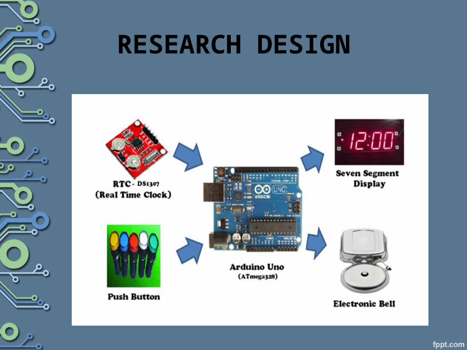
RESEARCH DESIGN

Research Instrument
• The following are the main component, equipment and software that were used on making this project:
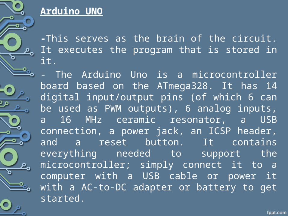
Arduino UNO
-This serves as the brain of the circuit. It executes the program that is stored in it.- The Arduino Uno is a microcontroller board based on the ATmega328. It has 14 digital input/output pins (of which 6 can be used as PWM outputs), 6 analog inputs, a 16 MHz ceramic resonator, a USB connection, a power jack, an ICSP header, and a reset button. It contains everything needed to support the microcontroller; simply connect it to a computer with a USB cable or power it with a AC-to-DC adapter or battery to get started.
Arduino IDE (Integrated Development Environment)
-this is where we sketch the command program and uploaded to the arduino hardware. - is a special program running on the computer that allows writing sketches for the arduino board in a simple language modeled after the processing language.
RTC -is used so the clock can continue to keep time even if the primary source of power is off or unavailable.
7-segment -This is where the time will be displayed in 24 hours format.
PUSHBUTTON- 4 pushbutton will be used in this project, for alarm set key, increment value, decrement value and time set key.
Proteus - is software for microprocessor simulation, schematic capture, and printed circuit board (PCB) design.

FLOWCHART
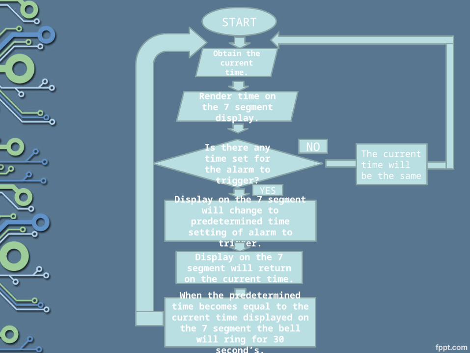
START
Obtain the current time.
Render time on the 7 segment display.
Is there any time set for the alarm
to trigger?
Display on the 7 segment will change to predetermined time
setting of alarm to trigger.
Display on the 7 segment will return on the current
time.
When the predetermined time becomes equal to the current
time displayed on the 7 segment the bell will ring for 30
second’s.
YES
The current time will be the same
NO
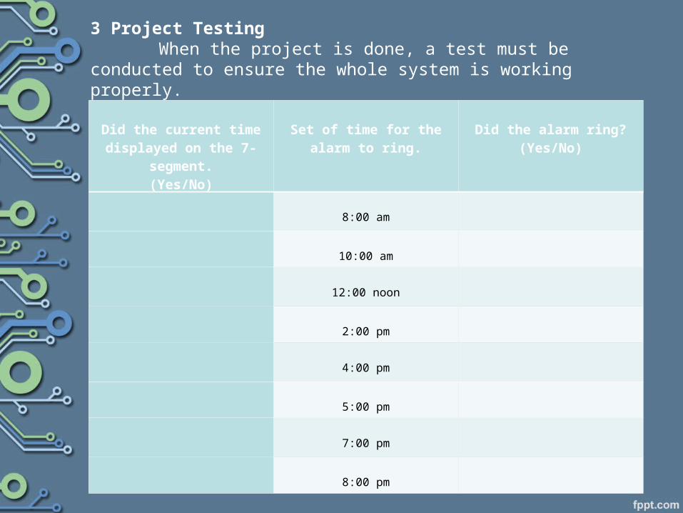
3 Project Testing When the project is done, a test must be conducted to ensure
the whole system is working properly.
Did the current time displayed on the 7-
segment.(Yes/No)
Set of time for the alarm to
ring.
Did the alarm ring?
(Yes/No)
8:00 am
10:00 am
12:00 noon
2:00 pm
4:00 pm
5:00 pm
7:00 pm
8:00 pm
Recommended