The Mt. Erebus Explorer Control System Daniel A. Christian
CMU-RI-TR-93- 19
The Robotics Institute Camegie Mellon University
5000 Forbes Avenue Pittsburgh, PA 15213
June, 1993
42 1993 Camegie Mellon University
This work was funded by NASA under grant NAGW-2998 and NSF n0derU.S. Antarctic Research Program project S-081.


Table of Contents
Project Overview 1 Robot Description 2
Frame Advance Mechanism 3 Height Adjustment 4 Tether Reel 4 Foot Sensors 5 Terrain Perception 5 Telemetry 5 Other Sensors 6 Other Controls 6 Science Equipment 7
Dank Control Computer 8 Base Station 8 Goddard Station 9
Physical Control Algorithms 9 Architecture Overview 9 Overlapping Walking Cycle 11 Frame Phasing Algorithm 12 Overall Servo Loop 13 Motion Sequencing 13 Servo Modes 14 Synchronous Motion Control 16 Acceleration Control 16 Saturation Handling 17 2 Actuator Control 17 Frame Control 17 Tether Tension Control 18 Tether Level Wind Control 19 Idle Time Out 19 Motion Abort 19 System State Recording 20
Operator Interface 20 DISH 20 The Watch System 21 Flat Panel Terminal 22
Brake drivers 23 Potentiometer interfaces 23 Connectors and Wiring 23 Sensors Electronics 24 Power System 25
Computing 7
Electrical System 22
Field Experiences 25
i

Connectors 25 Tension Sensor 26 VME Boards 26 Inclinometer 27 Feet 27 Brushless Motors 28 Fiber Optic Connections 28
Conclusions 28
.. 11
List of Figures
Dank rappelling in Mt. Erebus. 2 Four bar mechanism. 3 Four bar velocity vs crank angle. 4 System computing overview 7 Control system process map. 10 Frame phases in angular and linear cycles. 11 Vehicle reaction forces. 18 Servo control system wiring 23 Noise insensitive potentiometer interface 24
... 111

iV

Abstract
In January 1992, NASA started a unique, one year project in competitive robotics. The objective was to demonstrate robotic technologies for a scientific mission in the Mars like environment of Antarctica. A unique robot was built to rappel into an active volcano and retrieve pristine gas samples from near the con- vecting magma lake. Dante was deployed in Mt. Erebus, Antarctica December 1992 through January 1993.
The Mt. Erebus explorer, Dante, is an eight legged frame walker that can rappel down rugged terrain at slopes up to 90". Systematic constraints require Dank's control system to be highly capable, compact, light weight, and field worthy.
This paper describes the multi-processor control system that is responsible for coordinated motion control, foot fall sequencing, science control, dead reckon- ing, image collection, temperature regulation, and system safety. The critical control software, physical implementation, and field experiences are discussed.
V

vi

1. Introduction
The Mt. Erebus’ explorer project required the conception, design, and deploymenl of a robot for a difficult environment within a single year. This required a design strategy that balanced mature technologies against newer, more efficient ones. The resulting robot con- troller is remarkably small, light, efficient, and capable.
This paper presents the computational and electrical control system that provides the coordi- nated motions of the robot. The technical challenges of the robot, the resulting architecture, and field results are included.
2. Project Overview
The mobile robot, Dunte2, was developed by the Erebus Project to explore an active vol- cano, Mount Erebus, Antarctica at year-end 1992. The summit of Mount Erebus at 3794111 opens into a main crater, a 500m by 600m ovoid, approximately 150m deep. This main cra- ter contains an inner crater that holds one of the few convecting magma lakes in the world.
The robotic objectives are to achieve extended autonomy, environmental survival, and self- sustainable mission performance in the harsh Antarctic climate. The scientific objective of the project is to determine the composition of gas generated by the magma lake through both real time analysis and sample collection.
The descent route from the rim to the crater floor i s approximately 25Om long and progresses from a 55” slope at the rim to vertical drop into the crater. The route has numer- ous boulders (50cm typical), loose material, ice chimneys, and ledges. The surface compo- sition is widely varied and includes regions of snow, ice, rock, volcanic rock, mud, and ash. The surface may break through or break away when stepped on. The slope varies from 55” to 90”, severely limiting any ability to navigate around obstacles. No human intervention is possible while Dante is in the crater.
A more detailed descriptions of the robot and its mission are available in “Exploring Mount Erebus by Walking Robot”[l].
1. Erebus is pronounced Air‘-y-bus. 2. The robot is named Dank in reference u) the poem, The Divine Comedy by h t e Alegheri, in which Dmte travels to the underworld Erebus is a cloud of mist that obscures the entry to bell.
1
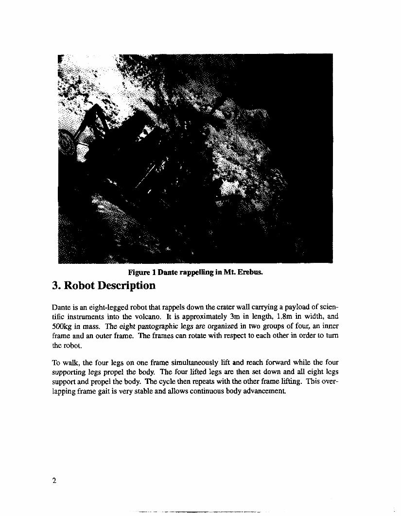
Figure 1 Dante rappelling in Mt. Erebus.
3. Robot Description
Dante is an eight-legged robot that rappels down the crater wall carrying a payload of scien- tific instruments into the volcano. It is approximately 3m in length, 1.8m in width, and 500kg in mass. The eight pantographic legs are organized in two groups of four, an inner frame and an outer frame. The frames can rotate with respect to each other in order to turn the robot.
To wak, the four legs on one frame simultaneously lift and reach forward while the four supporting legs propel the body. The four lifted legs are then set down and all eight legs support and propel the body. The cycle then repeats with the other frame lifting. This over- lapping frame gait is very stable and allows continuous body advancement.
2
Each of the legs can individually adjust its height in order to avoid obstacles and adapt to the rough terrain. A tether supports the weight of the robot on steep slopes allowing Dante to rappel'. The tether also provides power, digital telemetry, and video monitoring. A mast supports the perception sensors and main teleoperation camera. The control system and sci- ence instruments reside in sealed enclosures on either side of the central tether reel.
3.1. Frame Advance Mechanism
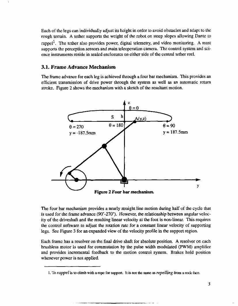
The frame advance for each leg is achieved through a four bar mechanism. This provides an efficient transmission of drive power through the system as well as an automatic return stroke. Figure 2 shows the mechanism with a sketch of the resultant motion.
.
y = -187.5mm y = 187.5mm
\ 1
# Figure 2 Four bar mechanism.
The four bar mechanism provides a nearly straight line motion during half of the cycle that is used for the frame advance (90"-270"). However, the relationship between angular veloc- ity of the driveshaft and the resulting hear velocity at the foot is non-linear. This requires the control software to adjust the rotation rate for a constant linear velocity of supporting legs. See Figure 3 for an expanded view of the velocity profile in the support region.
Each frame has a resolver on the final drive shaft for absolute position. A resolver on each brushless motor is used for commutation by the pulse width modulated (PWM) amplifier and provides incremental feedback to the motion control system. Brakes hold position whenever power is not applied.
1. To rappel is to climb with a rope for support. It is not the same. as repelling from a rock face
3
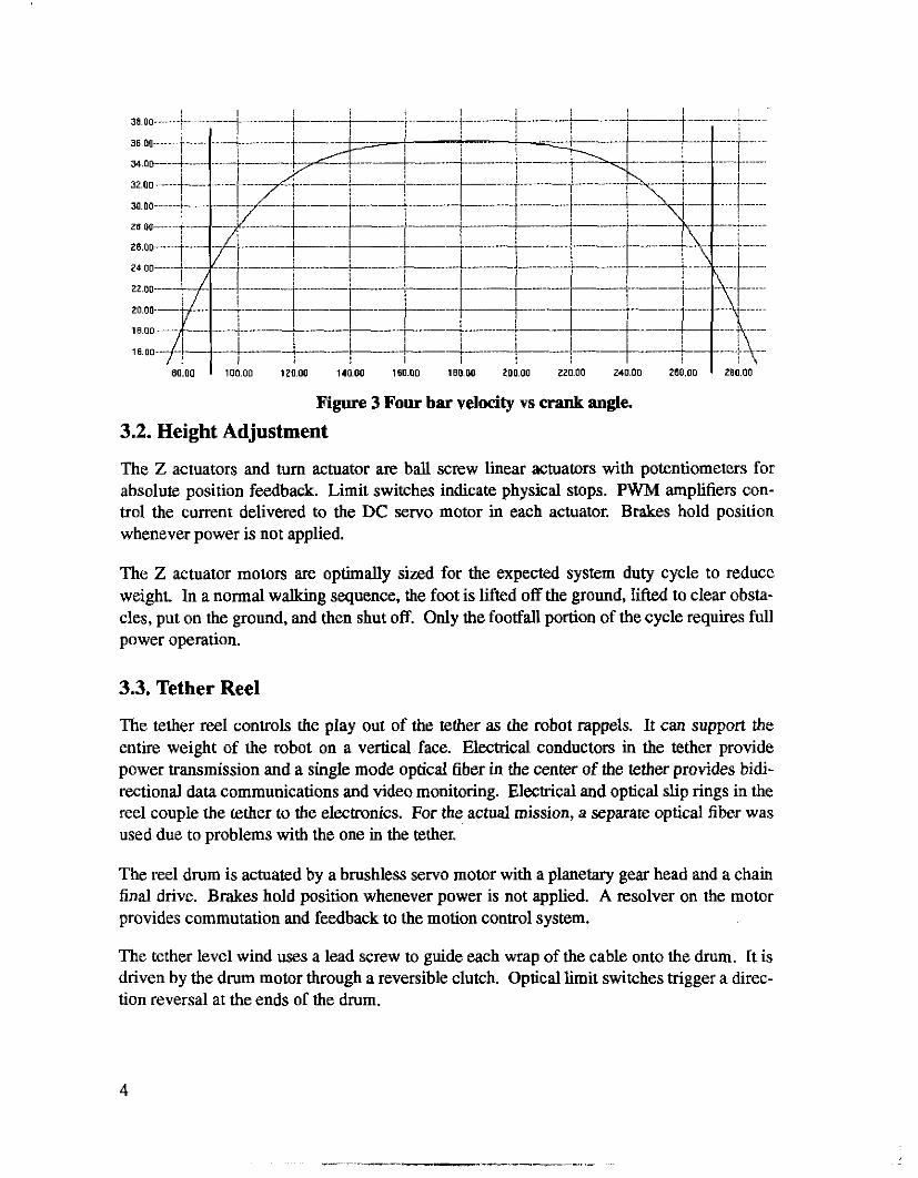
Figure 3 Four bar velocity vs crank angle.
3.2. Height Adjustment
The Z actuators and turn actuator are ball screw linear actuators with potentiometers for absolute position feedback. Limit switches indicate physical stops. PWM amplifiers con- trol the current delivered to the DC servo motor in each actuator. Brakes hold position whenever power is not applied.
The Z actuator motors are optimally sized for the expected system duty cycle to reduce weight. In a normal walking sequence, the foot is lifted off the ground, lifted to clear obsta- cles, put on the ground, and then shut off. Only the footfall portion of the cycle requires full power operation.
3.3. Tether Reel
The tether reel controls the play out of the tether as the robot rappels. It can support the entire weight of the robot on a vertical face. Electrical conductors in the tether provide power transmission and a single mode optical fiber in the center of the tether provides bidi- rectional data communications and video monitoring. Electrical and optical slip rings in the reel couple the tether to the electronics. For the actual mission, a separate optical fiber was used due to problems with the one in the tether.
The reel drum is actuated by a brushless servo motor with a planetary gear head and a chain final drive. Brakes hold position whenever power is not applied. A resolver on the motor provides commutation and feedback to the motion control system.
The tether level wind uses a lead screw to guide each wrap of the cable onto the drum. It is driven by the drum motor through a reversible clutch. Optical limit switches trigger a direc- tion reversal at the ends of the drum.
4
The entire reel and drive motor assembly are mounted on slides allowing it to press againsl a beam as tension is applied to the tether. A Linear Variable Displacement Transformer (LVDT) measures the deflection of the titanium beam to measure the tension. A high preci- sion ampliEer mounted at the LVDT conditions the signal for the control system.
The tether travels through a guide on the outer frame to provide a consistent control point. The tether exit angle is sensed in two directions by bails attached to potentiometers.
3.4. Foot Sensors
Each foot has a contact force sensor, an initial contact sensor, a capaciflector, and a tempera- ture sensor. A microcontroller monitors and controls these sensors and sends status updates to the control computer over a RS-422 serial line.
The capaciflector is a capacitance based proximity detector. Changes in the aggregate per- mittivity around the sensor change its resonant frequency. The capaciflector concept was developed at NASA Goddard for collision detection and adapted for direct microcontroller interfacing.
3.5. Terrain Perception
The “Hurricane” scanning laser range finder sits near the top of the sensor mast and scans the height of the ground around the robot from a radius of 4 to 12 meters. The scanner out- puts 12 bits of range and status which are Sent up the fiber optic link to the base station com- puters.
The multi-baseline stereo vision system uses three black and white cameras: a forward look- ing set and a rearward looking set. A digitizer in the onboard control computer digitizes the three cameras simultaneously and then passes the data to the base station computers through the ethemet link The digitizer selects between the two sets of cameras under software con- trol.
3.6. Telemetry
Six color cameras provide the operator with visual feedback of the operation of the robot. The main teleoperation camera mounts on top of the sensor mast and has pan, tilt, zoom, and focus control. The six cameras are multiplexed into three VHF modulators. Two micro- phones provide audio feedback to accompany the video.
The three VHF signals are combined and then block converted to UHF frequencies. The combined UHF signals are fed into a commercial analog laser transmitter.
5
The ethernet for the control computer is sampled at high rate (75Mhz) along with the laser range finder data and low speed serial ports by the “Data Rocket”. The multiplexed digital signals are fed to a digital laser. Another Data Rocket at the base station de-multiplexes the digital signals.
Because the distance from the robot to the base station is longer than is supported by ether- net collision timing, a two node version of ethemet is used which never has collisions. The Data Rocket generates the proper heartbeat to allow the ethernet interface to believe it is talking to a normal ethemet transceiver.
The digital and analog lasers operate at different wave lengths. An optical combiner merges the two lights onto the tether optical fiber. Because the analog signals are modulated at a much higher frequency than the digital, the two systems do not interfere with each other even when one signal leaks onto the other one due to reflections in the fiber.
3.7. Other Sensors
Two inclinometers mounted in the center of the inner frame measure body roll and pitch. This allows control of body pose and tether tension relative to the gravity.
Temperature sensors monitor enclosure, external, and tether electronics temperatures. External temperatures are logged for scientific use and the internal temperatures are used for heat regulation.
Voltage sensors monitor the critical system power supplies and main tether voltage. This allows detection of system overloading or marginal components.
3.8. Other Controls
The eight feet communicate through four serial ports which are multiplexed between inner and outer frames. The four feet in motion can be continuously monitored for force, proxim- ity, and temperature.
Power controls allow load balancing and temperature regulation. The science package, telemetry system, laser range finder, and heaters are controlled with separate control lines.
Each servo amplifier is independently enabled by the computer. The amp enable also auto- matically disables the brake on that axis. The current being deliveted by each amplifier is monitored for servo system tuning and to limit the temperature of the Z-axis motors.
An active deadman enables motion when the servo loop on the control computer is operat- ing at more than 100Hz. This insures that all motion is disabled unless the control computer is operating correctly.
6
3.9. Science Equipment
1 / I
I \
A pyrometer mount on the pan tilt with the telemetry camera measures the radiant tempera- ture of the lava from 260 to 1650°C. It constantly outputs data on a RS-232 line to the con- trol computer which relays it to the base station computers through ethernet.
A gas chromatograph (GC) and gamma ray spectrometer each communicate with RS-232 lines directly to a personal computer at the control station via the telemetry system.
The analog readings of gas flow, gas temperature, and the Quartz Crystal Micro balance stage frequencies are conditioned and monitored by control computer analog inputs.
The vacuum pump and Row control valves are controlled by digital outputs from the control computer.
4. Computing f
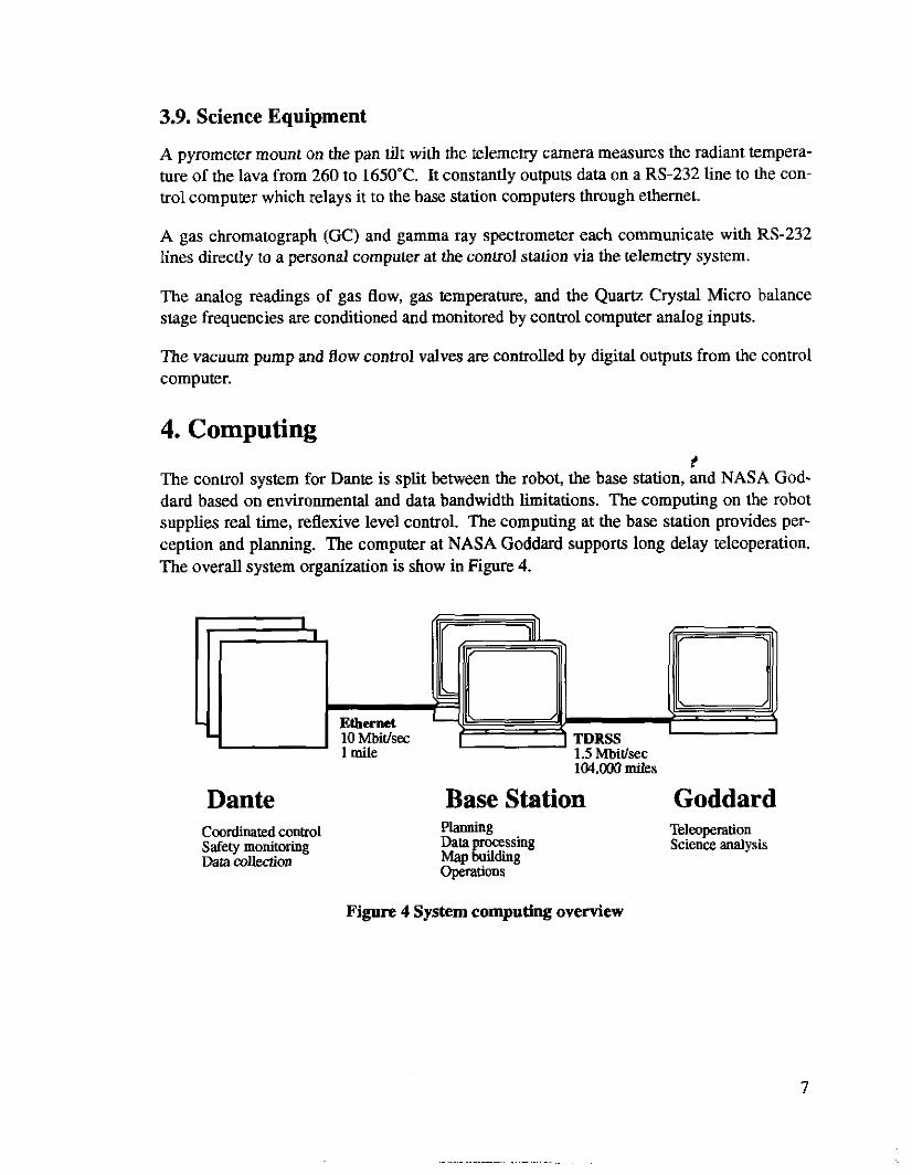
The control system for Dante is split between the robot, the base station, and NASA God- dard based on environmental and data bandwidth limitations. The computing on the robot supplies real time, reflexive level control. The computing at the base station provides per- ception and planning. The computer at NASA Goddard supports long delay teleoperation. The overall system organization is show in Figure 4.
Dante Base Station Goddard COOrdiMted COntrOl Safety monitoring DatamUectim
planning Data processing Map building operations
Telmperation Science analysis
Figure 4 System computing overview
4.1. Dante Control Computer
The system control electronics fit within a VME cage to minimize wiring and cooling. The VME mounted boards include the following: two 68030 CPUs, communications board, two analog/digital IO boards, servo control board, custom servo signal conditioning board, cus- tom high efficiency brake driver, custom sensor driverlconditioner board, full color frame buffer, and AC power control. System power supplies, motor amplifiers, video modulators, digital laser system, analog laser system, and heaters wrap around the VME cage withii a sealed enclosure.
The CPLJs, communication board, and system power supply are extended temperature rated to insure that system will at least boot far enough to communicate any problems. Other boards in the system were not available in extended temperature versions. The controller communicates with the base station computers using serial and ethernet links.
The control system software is stored in EPROM allowing basic motions from a directly connect flat panel terminal. Normally, the system is then rebooted off the base station to get the most current version of the control system.
The custom interface boards provide connector break out, signal conditioning, and surge suppression. These boards use a semi-custom board layout that has proto-board style con- nect rows with specific regions set aside for DIPS, PLCCs, or headers to suit the specific cir- cuitry needs. This approach required careful hand wiring of the circuitry, but allows very high wiring density and supports significant rework without ET board changes. A fully laid out printed circuit board for each interface board would have required extensive design time.
4.2. Base Station
The base station provides all the high level perception and planning for the robot and the operator interface. Three Sun SparcStations share the perception and planning computa- tional load. Each computer also has special interfaces to support the robot.
A SparcStation 1+ houses a video display and compression system to allow compressed live video to be sent via NASA's digital TDRSS satellite to NASA Goddard. The link is a Point to Point protocol (PPP) network established using a high speed buffered serial port and NASA supplied satellite communications equipment. The s a t e l k computer network also allows for long distance remote control of the robot, data transfer, and mission support.
Two other SparcStation IPXs provide general computing support and special interfaces. One IPX holds a second ethernet card for interfacing to the robot's laser ethernet link The other IPX holds at buffered 16 bit interface card for receiving the laser range finder data.
8
The high level perception and planning software uses multiple modules distributed across the Goddard workstations, base station workstations, and the control computer. A TCP/IF’ based communication system called TCX handles all inter-module control and data flow.
4.3. Goddard Station
The Goddard station mirrors the video sending computer at the base station. A SparcSta- tion 1+ houses a video display and decompression system to display live video sent via sat- ellite from Antarctica. Local control programs send commands to the robot via TCX for teleopexation.
5. Physical Control Algorithms
The control system software coordinates aLl actuation of the vehicle. Dante has 12 degrees of controlled motion: 8 leg heights, 2 frames, tether reel, and turn actuator. During a typical walking phase, 7 degrees of freedom must be synchronously controlled: 4 leg heights, 2 frames, and the tether reel.
The robot must be able to boot up without human intervention, warm itself until all sub- systems are within operational limits, determine its current state, and then open communica- tions with the base station. At any time, power loss must not result in a fall or other loss of control.
5.1. Architecture Overview
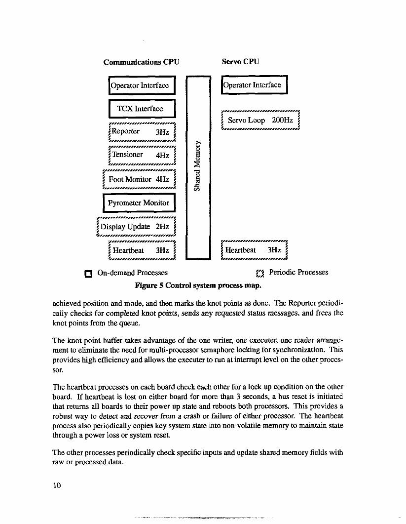
The control system is split over two processors: one for communication and one for servo control. Figure 5 illustrates the processes and organization of the two processors. The com- munications processor is approximately 20% utilized at rest and fully utilized when process- ing move requests or sending stereo images. The servo processor is approximately 90% utilized at all times.
The motion execution sequence is designed for continuous walking. A move is a interpola- tion from the last position knot point to the commanded one. As long as there is more than one knot point waiting to be executed, the system moves continuously through the knot points. When the no new knot points are available, motion stops at the last knot point.
At power up and after any fault, the last knot point is filled with the current position of the robot. All calculations for motion profiling and walk sequencing compare the last com- manded knot point with the desired goal. This allows calculations to directly reference either the current or expected position.
Motion knot points from the TCX Interface or Operator Interface are checked for validity and then turned into one or more low level h o t points. These knot points are inserted into a circular buffer in shared memory. The Servo Loop executes the knot points, records the
9
Communications CPU Servo CPU
Operator Interface u
$" Periodic Processes
Figure 5 Control system process map.
achieved position and mode, and then marks the knot points as done. The Reporter periodi- cally checks for completed knot points, sends any requested status messages, and frees the knot points from the queue.
The knot point buffer takes advantage of the one Writer, one executer, one reader arrange- ment to eliminate the need for multi-processor semaphore locking for synchronization. This provides high efficiency and allows the executer to run at interrupt level on the other proces- sor.
The heartbeat processes on each board check each other for a lock up condition on the other board. If heartbeat is lost on either board for more than 3 seconds, a bus reset is initiated that returns all boards to their power up state and reboots both processors. This provides a robust way to detect and recover from a crash or failure of either processor. The heartbeat process also periodically copies key system state into non-volatile memory to maintain state through a power loss or system reset.
The other processes periodically check specific inputs and update shared memory fields with raw or processed data.
10
5.2. Overlapping Walking Cycle
Dante uses an overlapping frame wallring cycle. This means that during part of the time all eight legs on both frame are supporting the body. The rest of the time, the four of the legs on one frame are “recovering” from the end of a stride to the start of the next stride while the other frame is supporting and propelling the body. The walking cycle can be thought of a repeating sequence of dual support, single support, dual support, single support.
The length of the stride is the sum of the forward stroke of the frame and the distance the body moves while the frame is recovering. The distance the body moves is determined by the relative rates of the two frames during the recovery. The recovery rate ratio can be directly calculated from the desired stride length.
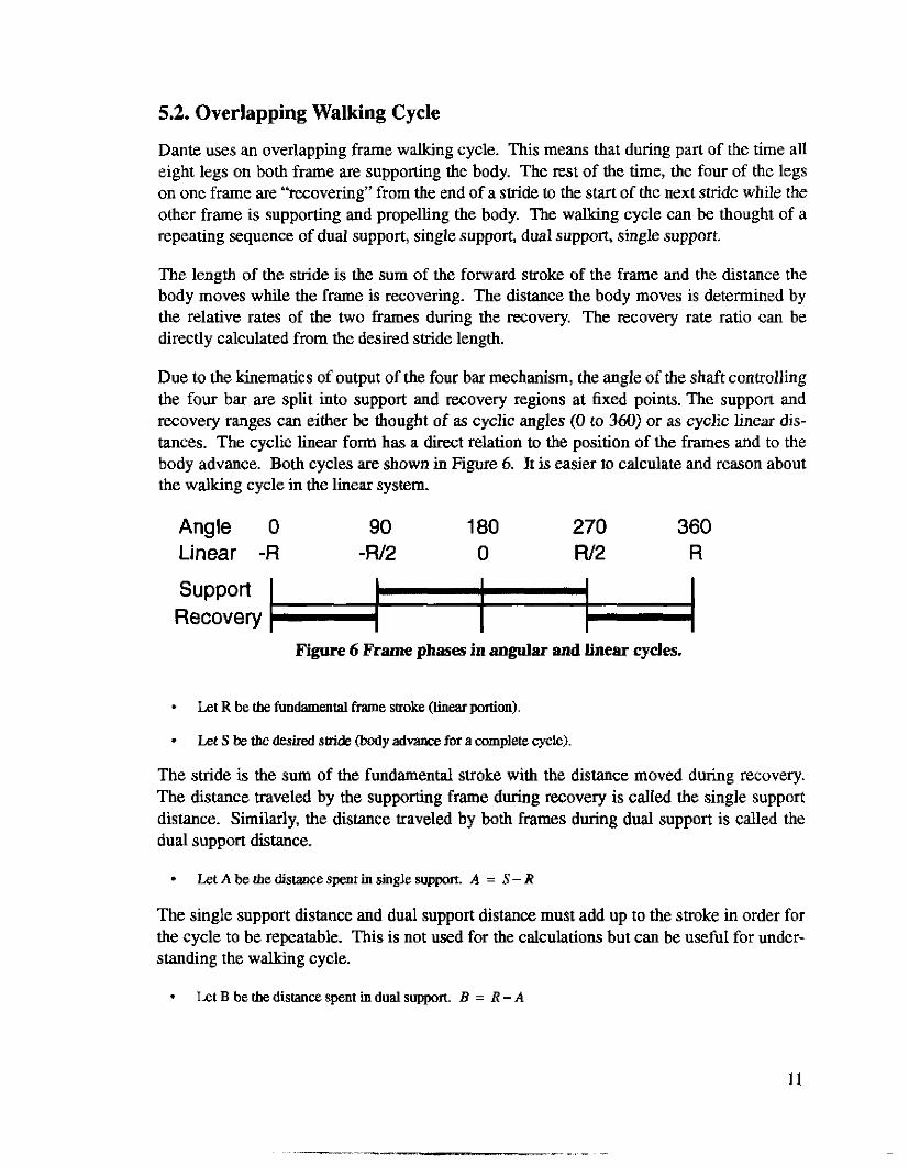
Due to the kinematics of output of the four bar mechanism, the angle of the shaft controlling the four bar are split into support and recovery regions at fixed points. The support and recovery ranges can either be thought of as cyclic angles (0 to 360) or as cyclic linear dis- tances. The cyclic linear form has a direct relation to the position of the frames and to the body advance. Both cycles are shown in Figure 6. It is easier to calculate and reason about the walking cycle in the h e a r system.
Angle 0 90 1 80 270 360 Linear -R -w2 0 w2 R
support Recovery
Figure 6 Frame phases in angular and linear cycles.
*
*
Let R be the fundamental frame stroke (linear portion)
Let S be the desired snide (body advance for a wmplete cycle).
The stride is the sum of the fundamental stroke with the distance moved during recovery. The distance traveled by the supporting frame during recovery is called the single support distance. Similarly, the distance traveled by both frames during dual support is called the dual support distance.
* LetAbetbe~stancespentinsinglesuppmr. A = S - R
The single support distance and dual support distance must add up to the stroke in order for the cycle to be repeatable. This is not used for the calculations but can be. useful for under- standing the walking cycle.
* LetBbetbedistancespentindualsuppon. B = R - A
11

The recovering frame must move through the recovery region in the distance that the sup- port frame is in single support. This determines the recovery ratio.
R * LelKbetberecoveryratio. K = - A
The spacing between the frames when they are in dual support is also determined from the stride.
S Let D be the spacing between frames in suppon. D = - 2
The spacing of the frames in support can also be varied separately from the pitch within limit A spacing of half the stride is symmetric for all steps. A larger spacing on one step may be matched to a correspondingly smaller later step for better control over foot place- ment.
D Let C be the maximum spacing deviation from D. C = R - - 2 *
5.3. Frame Phasing Algorithm
Each requested body advance is broken into variably sized sub-steps. This allows the body advance to be combined with vertical motions to produce arbitrary ground clearance profiles for the recovering legs. Small sub-steps also allow the non-linehties in the four bar mech- anism to be linearized.
At each sub-step, the proper positions of each frame are computed. Cumulative numerical errors after multiple cycles are avoided by calculating the correct frame phasing at each sub- step. Unreachable or unsafe positions are detected and reported.
All calculations are done in the linear cycle. At each step, positions are reduced to the fun- damental cycle range of R
- -
Let d be the old down frame position and d‘ be the new down frame position.
Let u be the old up frame position and u ’ be the new up frame position.
1.
2.
3.
If both frames are in recovery: Return illegal phasmg error.
Add tbe desired advance ta each frame pasition
If either frame entered or left !he s u p p a t region:
If both frame changed regions: Return illegal phasing error.
Find the frame that stayed in support.
If the non-support frame has left the support region: Gota step 5.
*
*
12
Figure the position of the non-suppon frame &om he support bame. I(' = d'?D
pick the one valid solution from the two possible solutions based on continuity. *
* Return new frame pmitions.
4.
5.
Are both frames supporting: Return new frame positions.
Calculate and return position of recovering frame from support frame U' = R / ~ x K x ( d + D - R / 2 )
Once the desired frame positions are calculated, the corresponding four bar shaft angles are calculated and inserted into the motion command. Sub-steps are limited to a small maxi- mum size (2.5mm) to minimize the non-linearity in the four bar velocities.
5.4. Overall Servo Loop
Control of each axis is synchronized and sequenced by the overall servo loop. At each servo tick (~OOHZ), the overall loop gets current system state from sensors, advances the motion sequence, activates each axis servo loop, checks for system saturation, and outputs the servo commands.
Whenever the feet on one of the frames goes into contact mode, the overall loop switches the foot communications to that frame and instructs the feet to report threshold crossings. When the feet leave contact mode, the new force thresholds are calculated and sent to the feet.
The temperature in the science and control enclosures is controlled by a simple set point loop. The heaters are only allowed on when the servo system is disabled to prevent exces- sive power draw.
5.5. Motion Sequencing
Move requests from either the operator interface or TCX interface are processed by the communications processor to check limits, convert to joint units, and split into multiple moves if needed. The low level move commands are placed in a circular buffer in the servo processors memory. This buffer always has at least one motion command in it. On initial- ization, a command is created which has the current positions and the "off" mode for each axis.
All moves involve the transition from the current motion command to a new motion corn- mand positions. When the move is complete, the current position of the system is stored in the move command for reporting.
The motion command structure is as follows:
13
..
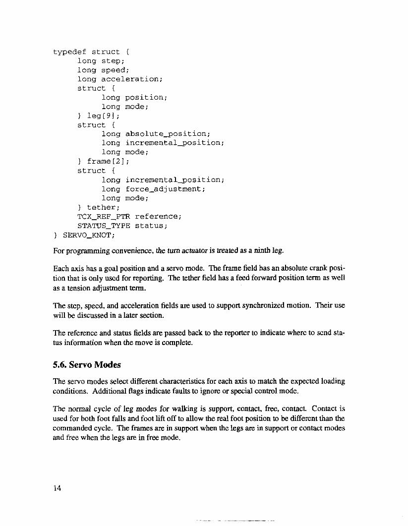
typedef struct I long step; long speed; long acceleration; struct {
long position; long mode;
leg[91; struct {
long absoluteqosition; long incrementalqosition; long mode;
) frameL21; struct {
long incrementalgosition; long f orce-ad] ustment ; long mode;
) tether; TCX-REF-PTR reference; STATUS-TYPE status;
) SERVO-KNOT;
For programming convenience, the turn actuator is treated as a ninth leg.
Each axis has a goal position and a servo mode. The frame field has an absolute crank posi- tion that is only used for reporting. The tether field has a feed forward position term as well as a tension adjustment term.
The step, speed, and acceleration fields are used to support synchronized motion. Their use will be discussed in a later section.
The reference and status fields are passed back to the reporter to indicate where to send sta- tus information when the move is complete.
5.6. Servo Modes
The servo modes select different characteristics for each axis to match the expected loading conditions. Additional Rags indicate faults to ignore or special control mode.
The normal cycle of leg modes for walking is support, contact, free, contact. Contact is used for both foot falls and foot lift off to allow the real foot position to be different than the commanded cycle. The frames are in support when the legs are in support or contact modes and free when the legs are in free mode.
14

5.6.1. Support For tether or frames, this is motion in contact with the ground. Joint velocities are limited to prevent jerking the vehicle.
For legs, this is the same as off. The force on the legs is maintained by the brakes allowing the motors to cool.
5.6.2. Contact
Contact mode is only valid for legs. The contact mode indicates a motion to or from ground contact.
Ground contact is determined by the force on the feet crossing a preset threshold. For each leg, the threshold is based on the expected weight on the leg given the vehicle center of gravity and body pitch with respect to gravity. The thresholds are highest on level ground and lowest on a vertical wall.
When the leg is moving down and the contact force rises above the threshold, the axis holds at the current position. If contact is then lost, the foot murnes its downward motion until the goal position is reached or contact is re-established. On upward moves, the foot does not move until the motion profile rises above the current position. This behavior insures good foot falls on shifting rock and crusty snow where transient contact is common.
Maximum joint velocity is allowed since the leg does not have to control the body mass, which is still being supported by the legs on the other frame.
5.6.3. Free Free mode indicates motion through the air with no expected contact. Any contact force on the legs indicates an obstruction and initiates a fault. Maximum joint velocities are allowed.
5.6.4. Lift
Lift mode is only valid for legs. It indicates that the motion is made while in contact with the ground under body weight. Lift mode is used for height, pitch, and roll moves.
Joint velocity is limited to prevent run away when lowering the body or excessive power draw when raising the body.
5.6.5. Limp
Limp mode is used for manually moving axis for servicing. The axis brakes are released, but the servo loop is left disabled. The position goal is ignored and no faults are detected.
5.6.6.0ff
Off mode is used for inactive axes. The servo axis is disabled. The position goal is ignored and no faults are detected.
15
5.7. Synchronous Motion Control
In order to synchronized the motion of all axis, an independent parameter, the “step”, is used to sequence the motion advance. The step varies from 0 to OxFFFF as the move progresses from start to finish. The step range is a fixed power of 2 to speed up the motion interpolation calculation.
At each servo tick, the current step is passed to the individual servo axis. Each axis figures its current position by interpolating bemeen the last position command and the new com- mand.
Since the step range is fixed regardless of the move length, resolution limitations can be a problem on long moves. The useful move range includes all possible Z axis moves and all useful moves for the frames and tether. Of course, long moves can always be subdivided to avoid the problem completely.
5.8. Acceleration Control
Each servo axis has an experimentally derived maximum velocity under both loaded and unloaded conditions. This is used to limit the synchronous system velocity to the slowest moving axis. The system velocity is controlled by the speed field in the motion command. This defines the maximum rate to increment the step at each servo tick.
Because the step range is independent of the motion distance, the system velocity is calcu- lated as an appropriately scaled step rate. Similarly, a system acceleration value is calcu- lated that indicates the proper rate to increase and decrease the system velocity.
The move sequencer modifies current system velocity by the current acceleration until the desired system velocity is achieved. This normally executes a trapezoidal velocity profile move.
The move sequencer constantly looh ahead to upcoming moves to check the next move velocity. If the next velocity is lower than the current velocity, the current velocity is ramped down to the new velocity at the appropriate time. If there are no more moves in the buffer, the next velocity is taken to be 1.
Because the move sequencer only looks one move ahead for deceleration, the moves are velocity profiled before being added to the queue to limit velocity change per move com- mand.
16
5.9. Saturation Handling
Each axis servo loop returns an indication of saturation to the main loop. Whenever satura- tion is detected, the current velocity is reduced by the acceleration rate. The velocity is lim- ited to be greater than zero, insuring that the goal position will eventually be reached or that a motion fault will be generated.
This regulates the system load at the maximum deliverable output through transient satura- tion conditions. Long term static saturation (e.g. a jammed actuator or a failed amp) will generate a motion fault before a loss of stability can occur.
5.10. Z Actuator Control
The Z actuator servo system is a software PID loop which uses potentiometer feedback for position and a voltage output to drive the motor amplifiers. The foot force sensor is used to detect contact.
The legs have a wide variation in loading from lifting during recovery to pushing down in a body lift. The loading variation is widest when walking on Bat ground and almost non exis- tent on a vertical face. The P D coefficients for the servo system were estimated using stan- dard Ziegler-Nichols techniques[2]. Further hand tuning of the gains and the integrator limiter yielded acceptable performance.
Saturation is indicated whenever the desired output from the servo law is greater than the output range of the analog output.
The actual motor current indicated by the amplifiers is integrated to detect continuous high load operation. The limit threshold is set conservatively since the current does not accu- rately indicate the power delivered to the motor. Once the threshold is crossed, motion on the hot motor is inhibited until the integrator returns to a low threshold.
The turn actuator is handled as a degenerate case of the Z actuator. It can never generate contact or limit faults.
5.11. Frame Control
The frame motors are controlled by a high bandwidth motion control board. The software servo loop simply computes the current knot point and passes it to the servo board. The servo output value of the board is read and compared with the maximum possible value to indicate saturation.
The servo boards use HPCTLllOO servo chips running a position servo loop at a 2KHz loop rate. These chips use a pole-zero compensating filter. Because the servo chip loop rate is much higher than the 200Hz main loop rate, the filter is tuned to dampen response above 200Hz.
I "
5.12. Tether Tension Control
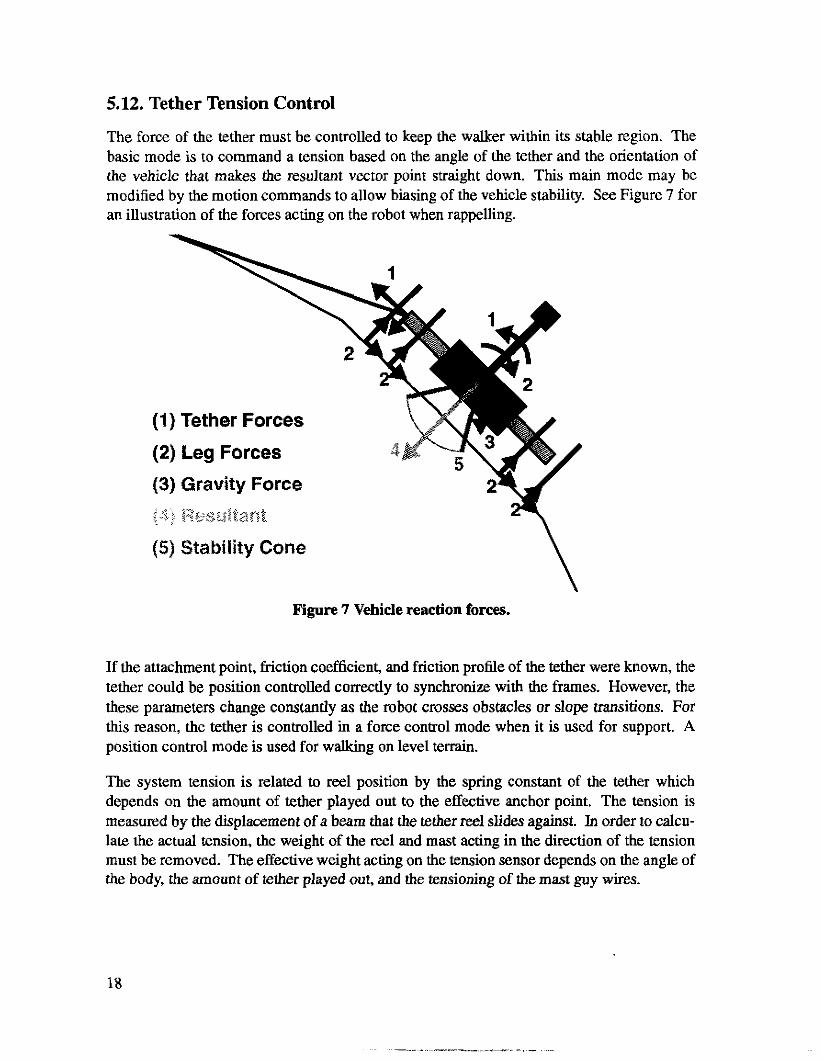
The force of the tether must be controlled to keep the walker within its stable region. The basic mode is to command a tension based on the angle of the tether and the orientation of the vehicle that makes the resultant vector point straight down. This main mode may be modified by the motion commands to allow biasing of the vehicle stability. See Figure 7 for an illustration of the forces acting on the robot when rappelling.
(1) Tether Forces
(2) Leg Forces
(3) Gravity Force
Figure 7 Vehicle reaction forces.
If the attachment point, friction coefficient, and friction profile of the tether were known, the tether could be position controlled correctly to synchronize with the frames. However, the these parameters change constantly as the robot crosses obstacles or slope transitions. For this reason, the tether is controlled in a force control mode when it is used for support. A position control mode is used for wallcing on level terrain.
The system tension is related to reel position by the spring constant of the tether which depends on the amount of tether played out to the effective anchor point. The tension is measured by the displacement of a beam that the tether reel slides against. In order to calcu- late the actual tension, the weight of the reel and mast acting in the direction of the tension must be removed. The effective weight acting on the tension sensor depends on the angle of the body, the amount of tether played out, and the tensioning of the mast guy wires.
18
The tension control loop is a proportional servo loop implemented around an inner position control loop. A feed forward position term from the desired walking body advance avoids contention with the frames. A dead band reduces “hunting” due to hysteresis in the tension sensor. The tension error term is slew rate limited to avoid servo system wind up. The inner position servo loop is implemented by a high bandwidth servo card using a pole zero com- pensation algorithm.
One difficulty with tether tension control is enabling the servo under fully loaded conditions. The is accomplished by biasing the initial desired position with the tension prior to enabling the servo loop. This compensates for the steady state sag in the position servo system. A software position-integral-derivative (PID) servo loop was tried to achieve tighter tension control, but the resultant gains were too low to be practically implemented in an integer based control system.
5.13. Tether Level Wind Control
The tether level wind must be reversed when one of the limit switches is contacted. At each reversal, the position of the reel in recorded to determine if the reel is changing to a higher or lower layer. The layer count is used by the system to determine the effective diameter and current mass of the reel. The current layer count is stored in non-volatile memory for continuity through power cycles.
If the tether reeling direction changes while one of the limit switches is still contacted, the required reversal will not be executed. The contact switch contact time is extended by hys- teresis in the contact switch and play in the drive clutches. This condition can cause the level wind to jam against the hard stop. Additional software can detect an early reversal and handle it appropriately.
5.14. Idle Time Out
When motion reaches the last command in the buffer, the system decelerates to a stop and holds in the current modes. If the system holds on the last position for more than 3 seconds, the leg motors are turned off (resting on brakes) to avoid high power dissipation in the motors longer than their rated duty cycle.
5.15. Motion Abort
Each axis servo loop checks for excessive motion error and any sensor faults. Further checks for unexpected contact depend on the current execution mode. Any invalid mode indicates corrupted memory and causes a power down.
When an abort is issued either by the operator, kill switch, or motion fault; all axis are turned off and motion commands in the buffer are marked as killed and complete. The reporter will then clear them from the buffer and report the exception.
19
. . .. - . ,
5.16. System State Recording
Each servo axis records state data in a circular buffer for system tuning. The commanded position, real position, commanded motor current, real motor current, and servo mode are recorded. The Z axis servo loop also records the foot contact force. The tether servo loop also records tether tension.
The overall servo loop records motion sequencer state, body inclination, tether angle, sys- tem voltages, and saturation level.
This information allows analysis of the system dynamic response and state transitions. Recording is enabled when the system is moving allowing the last 20 seconds of motion to be reviewed at any time. This is the primary mechanism for debugging the servo loops, since print statements cannot be executed at servo rates.
The data can be displayed at various resolutions as either an oscilloscope style graph or in tabular format. Summaries of the minimum and maximum values are also provided. The oscilloscope format allows resonance and servo lag to be visualized. The tabular format allows verification of the exact servo stimulus and response.
6. Operator Interface
The robot is controlled either from the directly attached flat panel terminal or through a remote ethernet connection. At power up and whenever a fault is detected, the operator inspects the state of the robot, makes any necessary manual moves to establish safe footing, and then enables TCX to send motion knot points from the planner.
6.1. DISH
DISH is the Dynamic Interactive SHell. Dish creates an efficient text based user interface that can be used on any terminal. Dish uses a programmable command description to define calls to C functions. Most of the time, existing system functions are directly called from the user interface. This allows new functions to be quickly tested from the user interface with minimal programming.
Arguments to commands may be specified in several ways to be natural for a user to work with. Numbers can be entered in decimal, octal, or hexadecimal formats. Integer mathe- matical operations are supported for all numeric arguments. Multi-word strings are enclosed in quotes and do not waste system memory. Keywords from a list are allowed and may be converted to numbers when the function is called. Hidden arguments pass in system constants.
20
Numeric arguments may define a default value and a valid range. The default value simpli- fies repeated function calls and speeds up standard usage. The range error checking often catches typos, missing arguments, or inappropriate function usage.
The user interface support interactive command completion for the function and its argu- ments. Help messages prompt the user for the expected argument type, default, and appro- priate range of values. Anywhere a keyword or function name is expected, an unique abbreviation is allowed.
The text interface supports Emacs style editing on all terminal types. Command history allows previous commands to be called up, edited, and re-issued.
Command descriptions from multiple modules may be layered into the user interface to sys- tematically support special functions. For the Dank control interface, special “expert only” commands and direct board control commands were added as separate layers. For example, the command “daadio dac 0 99” accesses the “dac” command under the “daadio” layer to directly control the Daadio interface board. The Daadio command set was previously writ- ten for the board device driver and was included under the user interface with two lines of code.
There are 75 commands that control the robot, provide debugging, set parameters, translate units, and display state. Other commands allow direct access to the interface boards for debugging or special functions. Additional utility commands provide general system and debugging functions.
The standard DISH utility commands are often useful for debugging. For example, the command “move 0x1 1o00, sleep 2; shutdown” tells the system to move axis 1 to position loo0 and abort after two seconds. This simple technique gives the axis enough time to reach its destination if things are working properly, but shuts off in case of an undetected fault.
Dish was written for an earlier project and re-used with minimal additions for the Dante control interface.
6.2. The Watch System
The watch system is a process that maintains a display of all system state on a terminal. This continuous state display proved to be invaluable in understanding and operating the large number of functions in the robot.
The watcher periodically checks for changes in a list of variables and updates the changed fields on the display with the new values. This optimized display allows a large number of fields to be displayed over a low bandwidth communications port. The display could be brought up on the main control terminal, in a separate telnet window, or on the flat panel dis- play.
21
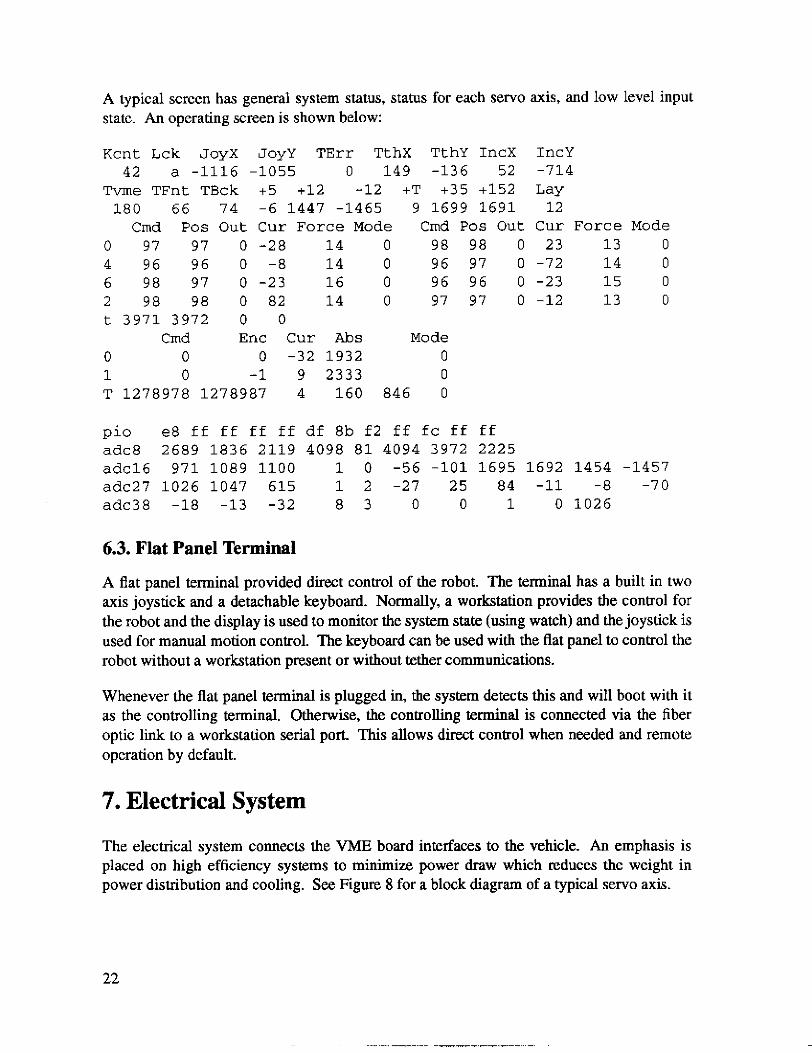
A typical screen has general system status, status for each servo axis, and low level input state. An operating screen is shown below:
K c n t L c k JoyX JoyY T E r r T t h X TthY IncX
Tvme TFnt TBck +5 +12 -12 +T +35 +152 42 a -1116 -1055 0 149 -136 52
180 66 74 -6 1447 -1465 9 1699 1691 Cmd Pos O u t Cur Force Mode Cmd Pos O u t
0 97 97 0 -28 14 0 98 98 0 4 96 96 0 -8 14 0 96 97 0 6 98 97 0 -23 16 0 96 96 0 2 98 98 0 82 14 0 97 97 0 t 3971 3972 0 0
Crnd Enc Cur Abs Mode 0 0 0 -32 1932 0 1 0 -1 9 2333 0 T 1278978 1278987 4 160 846 0
IncY -714
12 Cur Force Mode 23 13 0 -72 14 0 -23 15 0 -12 13 0
Lay
p i 0 e8 ff ff ff ff df 8b f2 ff fc ff ff adc8 2689 1836 2119 4098 81 4094 3972 2225 adcl6 971 1089 1100 1 0 -56 -101 1695 1692 1454 -1457 adc27 1026 1047 615 1 2 -27 25 84 -11 -8 -70 adc38 -18 -13 -32 8 3 0 0 1 0 1026
6.3. Flat Panel Terminal
A flat panel terminal provided direct control of the robot. The terminal has a built in two axis joystick and a detachable keyboard. Normally, a workstation provides the control for the robot and the display is used to monitor the system state (using watch) and the joystick is used for manual motion control. The keyboard can be used with the flat panel to control the robot without a workstation present or without tether communications.
Whenever the flat panel terminal is plugged in, the system detects this and will boot with it as the controlling terminal. Otherwise, the controlling tenninal is connected via the fiber optic link to a workstation serial port. This allows direct control when needed and remote operation by default.
7. Electrical System
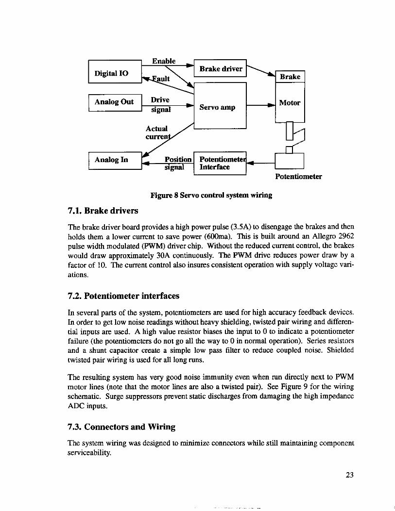
The electrical system connects the VME board interfaces to the vehicle. An emphasis is placed on high efficiency systems to minimize power draw which reduces the weight in power distribution and cooling. See Figure 8 for a block diagram of a typical servo axis.
22
Brake driver Brake I -
- s ignal Servo amp
Potentiometer
Figure 8 Servo control system wiring
7.1. Brake drivers
The brake driver board provides a high power pulse (3.5A) to disengage the brakes and then holds them a lower current to save power (600ma). This is built around an Allegro 2962 pulse width modulated (PWM) driver chip. Without the reduced current control, the brakes would draw approximately 30A continuously. The PWM drive reduces power draw by a factor of 10. The current control also insures consistent operation with supply voltage vari- ations.
7.2. Potentiometer interfaces
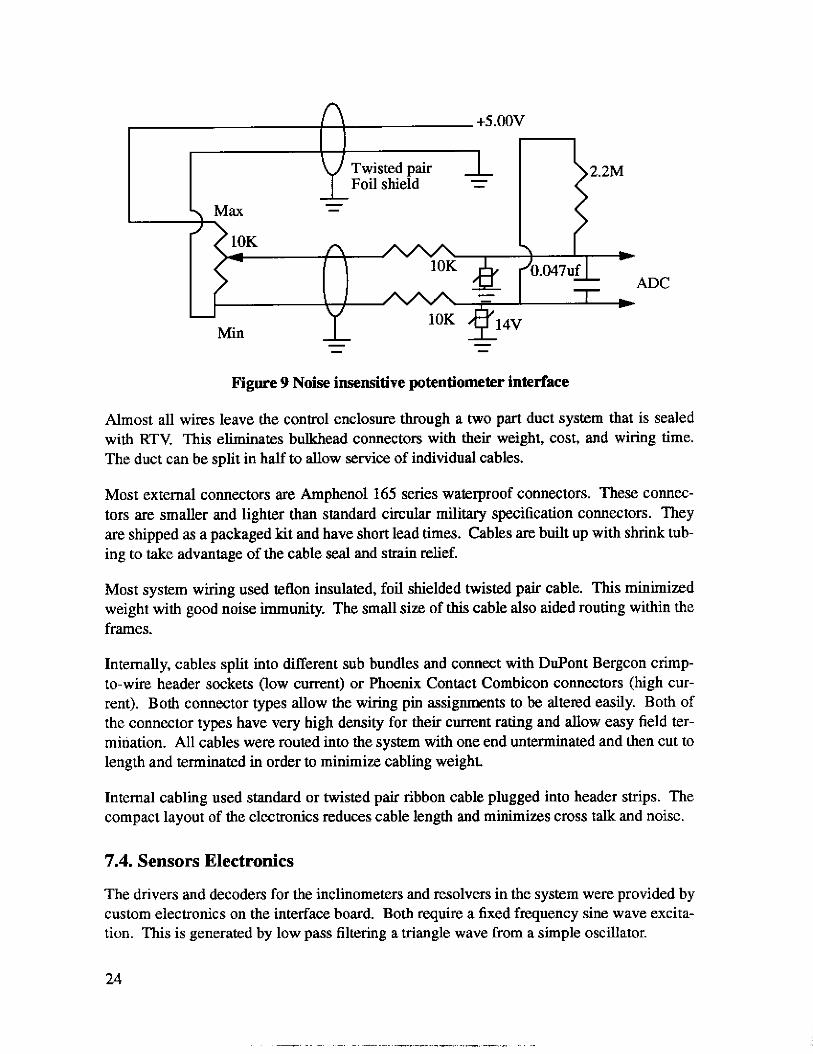
In several parts of the system, potentiometers are used for high accuracy feedback devices. In order to get low noise readings without heavy shielding, twisted pair wiring and differen- tial inputs are used. A high value resistor biases the input to 0 to indicate a potentiometer failure (the potentiometers do not go all the way to 0 in normal operation). Series resistors and a shunt capacitor create a simple low pass filter to reduce coupled noise. Shielded twisted pair wiring is w d for all long runs.
The resulting system has very good noise immunity even when run directly next to PWM motor lines (note that the motor lines are also a twisted pair). See Figure 9 for the wiring schematic. Surge suppressors prevent static discharges from damaging the high impedance ADC inputs.
7.3. Connectors and Wiring
The system wiring was designed to minimize connectors while still maintaining component serviceability.
23
+5.OOV
Twisted pair Foil shield - -
- -
n 1 OK
ADC - - 1 OK
- - - - Min
+5.OOV
Twisted pair Foil shield - -
- -
n 1 OK
ADC - - 1 OK
- - - - Min
Figure 9 Noise insensitive potentiometer interface
Almost all wires leave the control enclosure through a two part duct system that is sealed with RTV. This eliminates bulkhead connectors with their weight, cost, and wiring time. The duct can be split in half to allow service of individual cables.
Most external connectors are Amphenol 165 series waterproof connectors. These connec- tors are smaller and lighter than standard circular military specification connectors. They are shipped as a packaged kit and have short lead times. Cables are built up with shrink tub- ing to take advantage of the cable seal and strain relief.
Most system wiring used tellon insulated, foil shielded twisted pair cable. This minimized weight with good noise immunity. The small size of this cable also aided routing within the frames.
Internally, cables split into different sub bundles and connect with DuPont Bergcon crimp- to-wire header sockets (low current) or Phoenix Contact Combicon connectors (high cur- rent). Both connector types allow the wiring pin assignments to be altered easily. Both of the connector types have very high density for their current rating and allow easy field ter- mination. All cables were routed into the system with one end unteminated and then cut to length and terminated in order to minimize cabling weight.
Internal cabling used standard or twisted pair ribbon cable plugged into header strips. The compact layout of the electronics reduces cable length and minimizes cross talk and noise.
7.4. Sensors Electronics
The drivers and decoders for the inclinometers and resolvers in the system were provided by custom electronics on the interface board. Both require a fixed frequency sine wave excita- tion. This is generated by low pass filtering a triangle wave from a simple oscillator.
24
The inclinometer decoder is a sample and hold that detects the amplitude at the peak of the waveform. The amplitude is proportional to the excitation amplitude and the angle of the inclinometer.
The resolver decoder uses the Analog Devices AD2S82A resolver to digital converter. This chip takes the excitation, sine, and cosine signals and provides complete decoding of the resolver to a 12bit digital signal. This chip was easy to use and is insensitive to noise or variation in the resolver excitation. The output enable is used to multiplex the two resolvers onto the same digital lines to reduce IO requirements.
7.5. Power System
Power is supplied down the tether at 6OOVAC. The step down transformer compensates for the normal losses in the tether and produces all the voltages needed by the system (120,105, and 25VAC). A toroidal type transform minimizes weight and spurious magnetic fields. A separate sense output voltage allows the tether voltage to be continuously monitored.
Standard servo power supplies rectify and filter the 105 and 25VAC voltages for the servo system. Built in shunt regulators are adjusted to limit the voltage built up during regenera- tion from exceeding the operating voltage of the servo amplifiers.
The power source for the robot is a 5KW portable generator with a 2KW UPS for backup. Due to the thin air, the generator is derated to 2KW during mountain operation. The step up transformer is housed with the UPS. A solid state relay with zero voltage turn on is used to control the power to the step up transformer to prevent very high initial surge currents.
8. Field Experiences
The technologies used in the robot are typical of rapid prototyping style development. Field experiences are valuable in understand how appropriate the technology was for the task.
8.1. Connectors
The DuPont crimp to wire header connectors needed to have a real latch on them. We used a 'L' shaped metal linger (bent wire wrap pin) soldered into the board to hold them in. This was effective but took extra work to unplug and care to install. We used the standard force contact which gave a easy insertion but had very little retaining force. High force contacts are available for improved holding force. Being able to remove or rearrange contacts was very useful for debugging several of the sensors. The crimp connections were done using the proper crimp tool and were completely reliable.
25
The ribbon connectors did not have latches because the commonly available side latches took up too much room on the board. Headers with compact face latches are available, but not common. The ribbon connectors had a high contact force and did not work loose under operation. However, it was possible to displace a connector when inserting boards in the card cage.
The Amphenol 165 water proof circular connectors need to he labeled for easier alignment when mating. The high density solder connections require careful inspection to prevent poor solder joints or shorts. There was a problem with ice and dirt building up in the con- nectors during system re-assembly. This can be fixed by capping the connectors when not in use.
8.2. Tension Sensor
The original tension sensor was a quarter bridge strain gauge that directly measured the force action on the tether reel. The output signal from the strain gauge had to be amplified by lo00 to be read by the computer analog inputs. Such high gains require the electronics to be very low noise and very stable over a wide temperature range. The first version of the electronics used a constant current excitation instead of the common resistive bridge to avoid the non-linearity of the bridge. The semiconductors in the constant current circuit had more noise, offset, and temperature drift than the non-linearities they avoided.
A simple quarter bridge circuit was used with an auto zero instrumentation amplifier. The auto zero circuit eliminated the offset voltage of the amplifier. However, temperature track- ing between the strain gauge and the rest of the bridge still presented temperature drift. Fur- ther work was abandoned because the strain gauge itself appeared to be drifting too much over time. A better implementation would use a full bridge strain gauge which has much better temperature tracking. A beam spring and LVDT position sensor with DC output were substituted in the final system.
The mechanics for the tension sensor also need careful consideration. Currently, there are interactions between the tether tension, mast guy wires, mast weight, inner frame motor, and enclosure loading as well as mechanical hysteresis in the system. The tension system needs to be much more carefully isolated with further improvements in the Sense mechanism.
8.3. VME Boards
The Matrix boards (MX330, MAXIO, and DAADIO) provided a very high amount of func- tionality in a small space with moderate power draw. The only problem was a lack of a driver for the serial channels on the communications board. We were assured that one was “on the way”, but we developed a driver in house before it was ready.
26

The Technology 80 model 7600 servo board required a modification to work properly. The analog output should swing t lOV, but the negative swing saturates at -7.5V. A review of the schematics and data sheets, revealed this as a fundamental limitation with the way the DAC is used. By changing the scaling resistors for a 6.5V output range, linearity is restored.
The other problem with the 7600 servo board is that the bus interface logic doesn’t work well with some high speed CPUs. A spurious DTACK bus signal would sometimes be gen- erated after a 7600 access, interfering with any current transfers. The solution was have the CPU grab the bus and hold it while talking to the 7600 board. That way proper timing can be guaranteed without any intervening bus transfers.
The HCTL-1100 servo controllers used on the servo boards worked well except for two problems. The recommended tuning method from Hewlett Packard, “Design of the HCTL 1000’s Digital Filter Parameters by the Combination Method” worked very poorly for this application. A review of the principles of pole zero compensators in the S plane proved to be more useful. The lack of a integral term in the servo law also allowed significant “sag” in the heavily loaded tether servo control.
The Eltec Full Color Frame Grabber worked well once the capture registers were properly set up. The different connectors for the two sets of RGB inputs was a nuisance. We discon- nected the on board termination resistor on the sync input and directly tied the sync input to the green input.
8.4. Inclinometer
The inclinometer system used had continuing problems with drift (repeatability of 0.1” is needed). This may be a problem with the sensor or with the drive and decode electronics. This particular sensor was chosen because we needed a +-90 degree range. A pendulum style inclinometer may have had better stability and a simpler interface.
8.5. Feet
The force sensors in the feet are read by a microcontroller and then sent over a serial line to the communication CPU which put the information in shared memory for the servo CPU. This process has low bandwidth (9600 baud), significant latency, and a wide variation in latency. A lower delay, higher bandwidth system is needed to allow repeatable foot con- tacts.
The microcontroller also provided the capaciflector control, but has not been used yet due to the difficulty in calibrating it to varying terrain. If the force feedback is reliable, the proxim- ity detection may not be needed.
27
8.6. Brushless Motors
The brushless motors used a factory mounted resolver for commutation and feedback. Hav- ing the resolver permanently mounted at the factory insured correct phasing, avoiding hand alignment. The amplifier decodes the resolver for commutation and also outputs a quadra- ture output signal for the motion control boards. This avoided a secondary optical encoder on the motor for feedback which would have added size and weight.
One problem that we had with the brushless motors was excessive ground noise during high current operation. This was causing the amplifiers to shutdown momentarily due to noise on the enable l i e . The solution was to optically isolate all digital connections to the amplifi- ers. The analog lines used differential inputs to cancel the noise.
8.7. Fiber Optic Connections
The single mode fiber in the tether requires very precise connectors to prevent signal losses and reflections. These connectors are specified to have low losses, but the factory installed connectors had much higher losses and sometimes require manual tweaking for proper mating. Wherever possible, optical cable pigtails were used to couple one component to the next one in the chain to minimize the number of connections. The time spent shipping com- ponents to a vendor for proper termination introduced a significant development time bur- den.
9. Conclusions
A series of innovative design ideas yielded a robust system for harsh environments in a very short development cycle. A novel coordinated servo algorithm allowed robust operation under extreme loading conditions. Experience gained from field operation has established the effectiveness of most systems and revealed the limitation in others. Many of the tech- niques used may be easily re-applied in other systems requiring a capable, compact control- ler.
28
References
[I] Wettergreen, D.; Thorpe C.; Whittaker W. “Exploring Mount Erebus by Walking
[2] Franklin, Powel, Enamin-Naeini “Feedback Control of Dynamic Systems.” Addison Robot” Intelligent Autonomous Systems 93 (1993).
Wesley (1986). p105-106.
29
Recommended