ORIGINAL PAPER
Tensile Strength of Geological Discontinuities Including IncipientBedding, Rock Joints and Mineral Veins
J. Shang1 • S. R. Hencher1,2,3 • L. J. West1
Received: 11 December 2015 / Accepted: 23 June 2016
� The Author(s) 2016. This article is published with open access at Springerlink.com
Abstract Geological discontinuities have a controlling
influence for many rock-engineering projects in terms of
strength, deformability and permeability, but their char-
acterisation is often very difficult. Whilst discontinuities
are often modelled as lacking any strength, in many rock
masses visible rock discontinuities are only incipient and
have tensile strength that may approach and can even
exceed that of the parent rock. This fact is of high
importance for realistic rock mass characterisation but is
generally ignored. It is argued that current ISRM and
other standards for rock mass characterisation, as well as
rock mass classification schemes such as RMR and Q, do
not allow adequately for the incipient nature of many rock
fractures or their geological variability and need to be
revised, at least conceptually. This paper addresses the
issue of the tensile strength of incipient discontinuities in
rock and presents results from a laboratory test pro-
gramme to quantify this parameter. Rock samples con-
taining visible, natural incipient discontinuities including
joints, bedding, and mineral veins have been tested in
direct tension. It has been confirmed that such disconti-
nuities can have high tensile strength, approaching that of
the parent rock. Others are, of course, far weaker. The
tested geological discontinuities all exhibited brittle fail-
ure at axial strain less than 0.5 % under direct tension
conditions. Three factors contributing to the tensile
strength of incipient rock discontinuities have been
investigated and characterised. A distinction is made
between sections of discontinuity that are only partially
developed, sections of discontinuity that have been locally
weathered leaving localised residual rock bridges and
sections that have been ‘healed’ through secondary
cementation. Tests on bedding surfaces within sandstone
showed that tensile strength of adjacent incipient bedding
can vary considerably. In this particular series of tests,
values of tensile strength for bedding planes ranged from
32 to 88 % of the parent rock strength (intact without
visible discontinuities), and this variability could be
attributed to geological factors. Tests on incipient mineral
veins also showed considerable scatter, the strength
depending upon the geological nature of vein develop-
ment as well as the presence of rock bridges. As might be
anticipated, tensile strength of incipient rock joints
decreases with degree of weathering as expressed in
colour changes adjacent to rock bridges. Tensile strengths
of rock bridges (lacking marked discolouration) were
found to be similar to that of the parent rock. It is con-
cluded that the degree of incipiency of rock discontinu-
ities needs to be differentiated in the process of rock mass
classification and engineering design and that this can best
be done with reference to the tensile strength relative to
that of the parent rock. It is argued that the science of
rock mass characterisation may be advanced through
better appreciation of geological history at a site thereby
improving the process of prediction and extrapolating
properties.
Keywords Geological discontinuities � Incipiency �Persistence � Rock bridges � Uniaxial tensile strength �Laboratory testing � Rock mass classification � Fracturedevelopment
& S. R. Hencher
1 Geomechanics Research Group, School of Earth and
Environment, University of Leeds, Leeds, UK
2 Department of Earth Sciences, University of Hong Kong,
Pok Fu Lam, Hong Kong, SAR, China
3 Hencher Associates Limited, Ilkley, UK
123
Rock Mech Rock Eng
DOI 10.1007/s00603-016-1041-x
1 Introduction
The International Society for Rock Mechanics (ISRM
1978a) defines ‘discontinuity’ as the generic term for
mechanical fractures in a rock mass that has zero or low
tensile strength. It is applied to such geological features as
open joints, weak bedding planes, weak schistosity planes,
weakness zones and faults. In practice, the term is also
often applied to any visible geological planar features
(including joints and veins) that can be observed in expo-
sures, in tunnels, in borehole walls, on photographs or
measured by ground radar scans even where these features
might and often do retain high strength and therefore
strictly fall outside the ISRM definition of a discontinuity.
In a similar way, whilst only open natural discontinuities
should be counted when determining Rock Quality Des-
ignation (RQD) as defined by Deere (1968) and Deere and
Deere (1989), in practice incipient discontinuities are also
included in the assessment, especially where dealing with
rock exposures rather than logging core. This might be a
conservative approach in some situations (rock mass would
be stronger and stiffer than that assumed on the basis of the
assigned RQD value) but certainly would give an inaccu-
rate representation of rock mass quality. This will of course
have ‘knock-on’ consequences when using RQD as part of
assessment of rock mass quality, likely behaviour, say, in
tunnel stability, and in determining numerical parameters
on the basis of empiricism. Where the presence of open
fractures is relied upon, say for open excavation or tun-
nelling using a roadheader, misrepresenting incipient dis-
continuities as if they lacked tensile strength in site
investigation descriptions, can lead to misunderstandings,
poor selection of equipment and contractual disputes
(Hencher 2014, 2015). A separate but important conceptual
point is that incipient discontinuities will propagate and
weaken over geological and engineering time as the result
of processes such as unloading and weathering (Hencher
2006; Hencher and Knipe 2007); the tests reported in this
paper need to be considered in this context of a develop-
mental process for discontinuities. Any discontinuity
observed in the field is at a particular stage of development
and if we are to characterise such discontinuities we need
to appreciate that their properties reflect long and often
complex, site-specific histories.
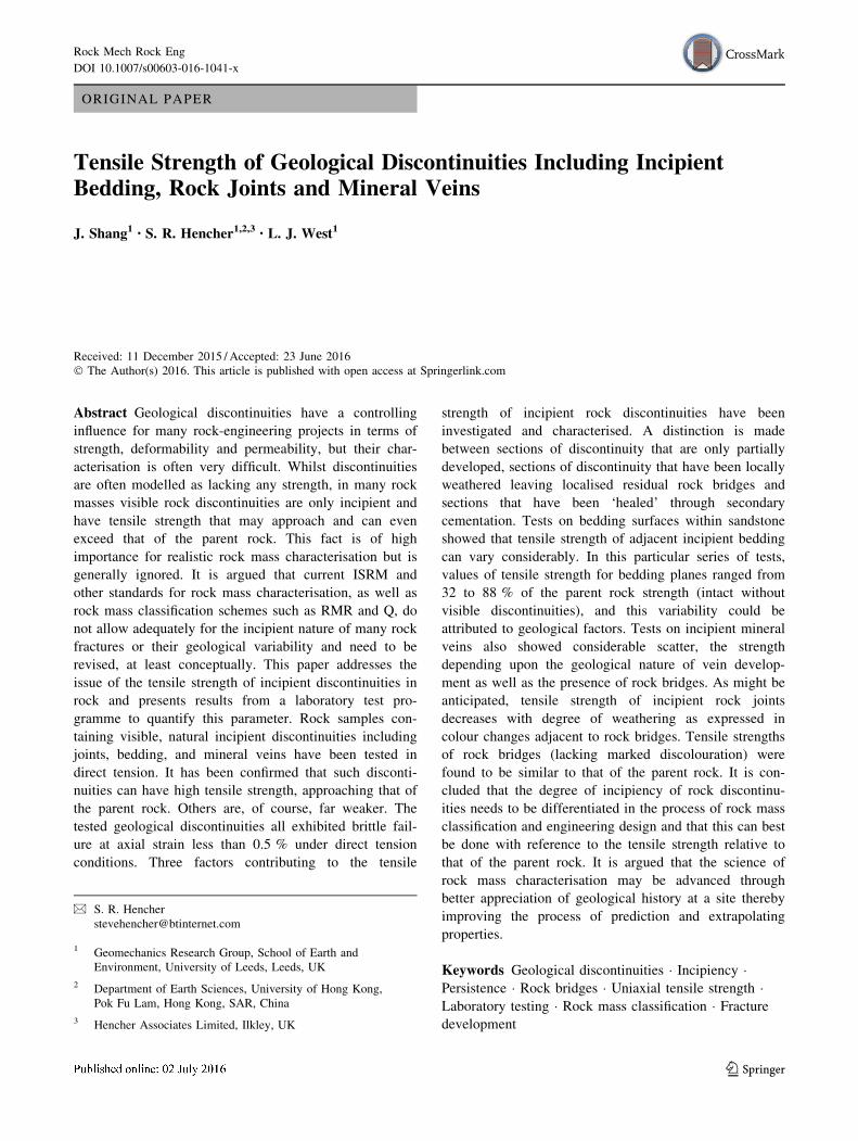
This is not a trivial observation as incipient rock dis-
continuities often have a controlling influence on rock mass
strength and stability. Tensile or shear failure of incipient
sections of fractures is often the ‘final straw’ leading to
instability. In exposures and tunnel roofs, many over-
hanging and threatening rock blocks or slabs remain in
place solely due to the incomplete development of the
bounding discontinuities as illustrated in Fig. 1.
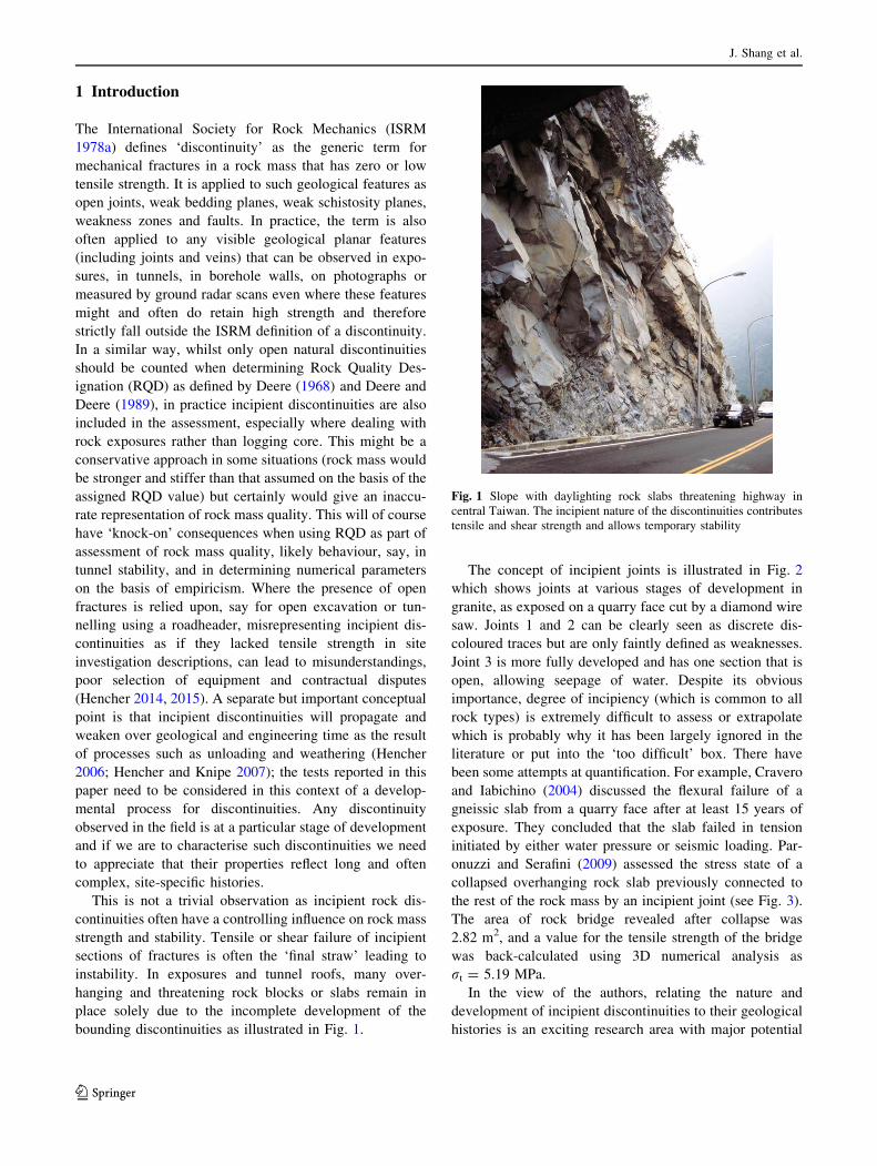
The concept of incipient joints is illustrated in Fig. 2
which shows joints at various stages of development in
granite, as exposed on a quarry face cut by a diamond wire
saw. Joints 1 and 2 can be clearly seen as discrete dis-
coloured traces but are only faintly defined as weaknesses.
Joint 3 is more fully developed and has one section that is
open, allowing seepage of water. Despite its obvious
importance, degree of incipiency (which is common to all
rock types) is extremely difficult to assess or extrapolate
which is probably why it has been largely ignored in the
literature or put into the ‘too difficult’ box. There have
been some attempts at quantification. For example, Cravero
and Iabichino (2004) discussed the flexural failure of a
gneissic slab from a quarry face after at least 15 years of
exposure. They concluded that the slab failed in tension
initiated by either water pressure or seismic loading. Par-
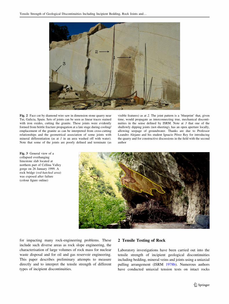
onuzzi and Serafini (2009) assessed the stress state of a
collapsed overhanging rock slab previously connected to
the rest of the rock mass by an incipient joint (see Fig. 3).
The area of rock bridge revealed after collapse was
2.82 m2, and a value for the tensile strength of the bridge
was back-calculated using 3D numerical analysis as
rt = 5.19 MPa.
In the view of the authors, relating the nature and
development of incipient discontinuities to their geological
histories is an exciting research area with major potential
Fig. 1 Slope with daylighting rock slabs threatening highway in
central Taiwan. The incipient nature of the discontinuities contributes
tensile and shear strength and allows temporary stability
J. Shang et al.
123
for impacting many rock-engineering problems. These
include such diverse areas as rock slope engineering, the
characterisation of large volumes of rock mass for nuclear
waste disposal and for oil and gas reservoir engineering.
This paper describes preliminary attempts to measure
directly and to interpret the tensile strength of different
types of incipient discontinuities.
2 Tensile Testing of Rock
Laboratory investigations have been carried out into the
tensile strength of incipient geological discontinuities
including bedding, mineral veins and joints using a uniaxial
pulling arrangement (ISRM 1978b). Numerous authors
have conducted uniaxial tension tests on intact rocks
Fig. 2 Face cut by diamond wire saw in dimension stone quarry near
Tui, Galicia, Spain. Sets of joints can be seen as linear traces stained
with iron oxides, cutting the granite. These joints were evidently
formed from brittle fracture propagation at a late stage during cooling/
emplacement of the granite as can be interpreted from cross-cutting
relationships and the geometrical association of some joints with
mineral differentiation (as at 1 in an area washed off with water).
Note that some of the joints are poorly defined and terminate (as
visible features) as at 2. The joint pattern is a ‘blueprint’ that, given
time, would propagate as interconnecting true, mechanical disconti-
nuities in the sense defined by ISRM. Note at 3 that one of the
shallowly dipping joints (not-sheeting), has an open aperture locally,
allowing seepage of groundwater. Thanks are due to Professor
Leandro Alejano and his student Ignacio Perez Rey for introducing
the quarry and for constructive discussions in the field with the second
author
Fig. 3 General view of a
collapsed overhanging
limestone slab located at
northern part of Cellina Valley
gorge on 26 January 1999. A
rock bridge (red-hatched area)
was exposed after failure
(colour figure online)
Tensile Strength of Geological Discontinuities Including Incipient Bedding, Rock Joints and…
123
(Hawkes et al. 1973; Okubo and Fukui 1996; Li et al. 2013;
Liu et al. 2014; Erarslan and Williams 2012). Saiang et al.
(2005) carried out uniaxial tension tests on the bond
between shotcrete and rock. A number of authors have
tested samples incorporating incipient discontinuities in a
general way. Barla and Innaurato (1973) and Dan et al.
(2013) found that tensile strength decreased with the
increase of the discontinuity orientation relative to the
uniaxial loading direction (from 0� to 90�). Khan and Irani
(1987) investigated the dynamic tensile strength of samples
that were cored perpendicular to bedding planes. In their
tests, the split Hopkinson bar was used to apply dynamic
loads.
3 Test Set-Up
3.1 Specimen Preparation
Large rock blocks containing incipient discontinuities were
collected from two locations. Samples of siltstone with
incipient mineral veins were taken from Dry Rigg Quarry,
Horton-in-Ribblesdale, North Yorkshire, UK. The Silurian,
Horton rocks are typically medium-to-dark grey sandy
siltstone with carbonaceous debris (King 1934; Arthurton
et al. 1988; Aitkenhead et al. 2002). Samples of medium-
grained sandstone containing incipient bedding planes and
joints were collected from Blackhill Quarry, West York-
shire, UK. The sandstone is from the Carboniferous Mid-
gley Grit formation and ranges from fine- to very coarse-
grained sandstone (Stevenson and Gaunt 1971; Waters
et al. 1996).
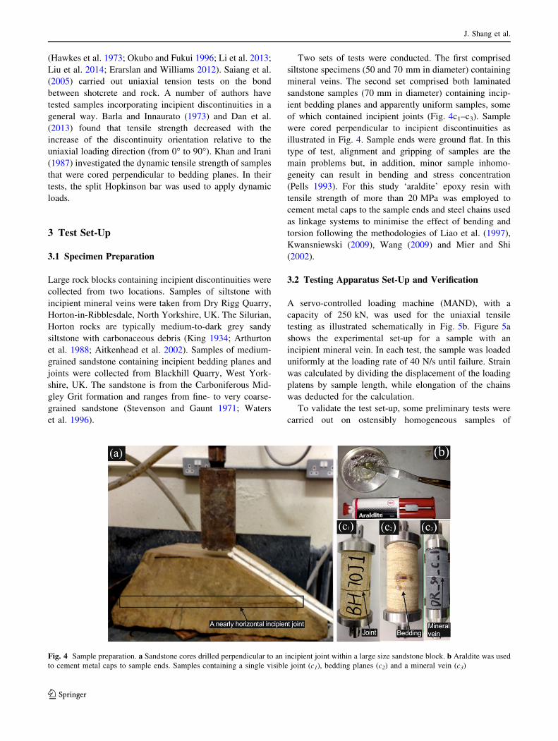
Two sets of tests were conducted. The first comprised
siltstone specimens (50 and 70 mm in diameter) containing
mineral veins. The second set comprised both laminated
sandstone samples (70 mm in diameter) containing incip-
ient bedding planes and apparently uniform samples, some
of which contained incipient joints (Fig. 4c1–c3). Sample
were cored perpendicular to incipient discontinuities as
illustrated in Fig. 4. Sample ends were ground flat. In this
type of test, alignment and gripping of samples are the
main problems but, in addition, minor sample inhomo-
geneity can result in bending and stress concentration
(Pells 1993). For this study ‘araldite’ epoxy resin with
tensile strength of more than 20 MPa was employed to
cement metal caps to the sample ends and steel chains used
as linkage systems to minimise the effect of bending and
torsion following the methodologies of Liao et al. (1997),
Kwansniewski (2009), Wang (2009) and Mier and Shi
(2002).
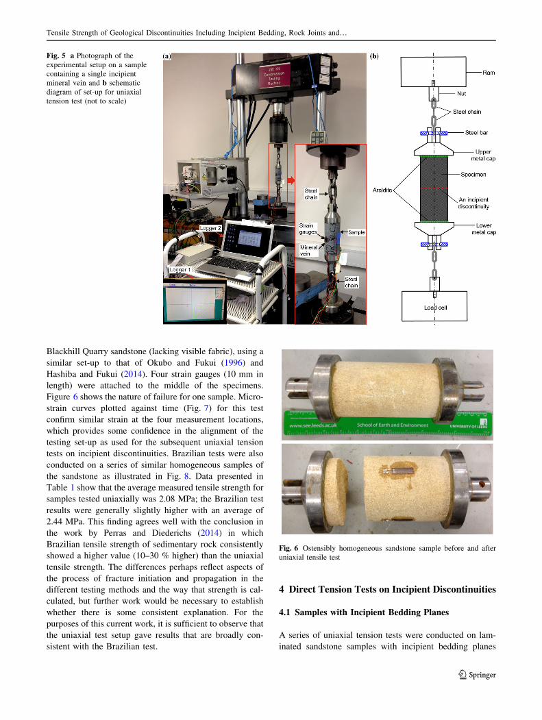
3.2 Testing Apparatus Set-Up and Verification
A servo-controlled loading machine (MAND), with a
capacity of 250 kN, was used for the uniaxial tensile
testing as illustrated schematically in Fig. 5b. Figure 5a
shows the experimental set-up for a sample with an
incipient mineral vein. In each test, the sample was loaded
uniformly at the loading rate of 40 N/s until failure. Strain
was calculated by dividing the displacement of the loading
platens by sample length, while elongation of the chains
was deducted for the calculation.
To validate the test set-up, some preliminary tests were
carried out on ostensibly homogeneous samples of
Fig. 4 Sample preparation. a Sandstone cores drilled perpendicular to an incipient joint within a large size sandstone block. b Araldite was used
to cement metal caps to sample ends. Samples containing a single visible joint (c1), bedding planes (c2) and a mineral vein (c3)
J. Shang et al.
123
Blackhill Quarry sandstone (lacking visible fabric), using a
similar set-up to that of Okubo and Fukui (1996) and
Hashiba and Fukui (2014). Four strain gauges (10 mm in
length) were attached to the middle of the specimens.
Figure 6 shows the nature of failure for one sample. Micro-
strain curves plotted against time (Fig. 7) for this test
confirm similar strain at the four measurement locations,
which provides some confidence in the alignment of the
testing set-up as used for the subsequent uniaxial tension
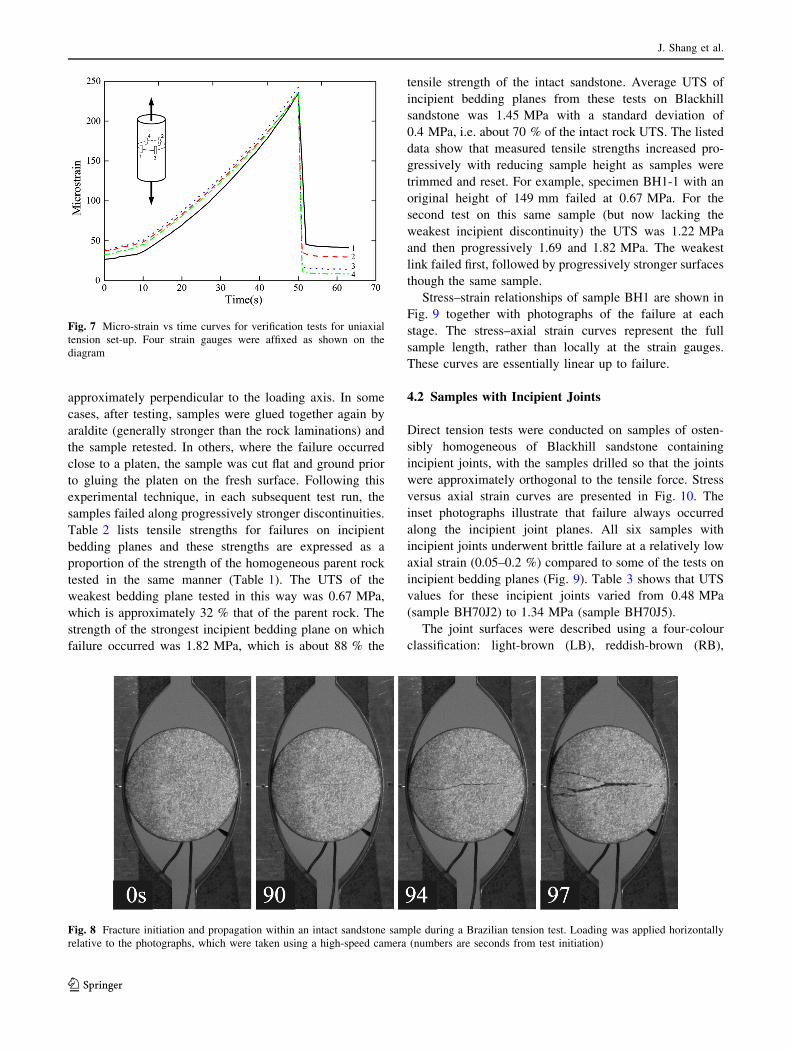
tests on incipient discontinuities. Brazilian tests were also
conducted on a series of similar homogeneous samples of
the sandstone as illustrated in Fig. 8. Data presented in
Table 1 show that the average measured tensile strength for
samples tested uniaxially was 2.08 MPa; the Brazilian test
results were generally slightly higher with an average of
2.44 MPa. This finding agrees well with the conclusion in
the work by Perras and Diederichs (2014) in which
Brazilian tensile strength of sedimentary rock consistently
showed a higher value (10–30 % higher) than the uniaxial
tensile strength. The differences perhaps reflect aspects of
the process of fracture initiation and propagation in the
different testing methods and the way that strength is cal-
culated, but further work would be necessary to establish
whether there is some consistent explanation. For the
purposes of this current work, it is sufficient to observe that
the uniaxial test setup gave results that are broadly con-
sistent with the Brazilian test.
4 Direct Tension Tests on Incipient Discontinuities
4.1 Samples with Incipient Bedding Planes
A series of uniaxial tension tests were conducted on lam-
inated sandstone samples with incipient bedding planes
Fig. 5 a Photograph of the
experimental setup on a sample
containing a single incipient
mineral vein and b schematic
diagram of set-up for uniaxial
tension test (not to scale)
Fig. 6 Ostensibly homogeneous sandstone sample before and after
uniaxial tensile test
Tensile Strength of Geological Discontinuities Including Incipient Bedding, Rock Joints and…
123
approximately perpendicular to the loading axis. In some
cases, after testing, samples were glued together again by
araldite (generally stronger than the rock laminations) and
the sample retested. In others, where the failure occurred
close to a platen, the sample was cut flat and ground prior
to gluing the platen on the fresh surface. Following this
experimental technique, in each subsequent test run, the
samples failed along progressively stronger discontinuities.
Table 2 lists tensile strengths for failures on incipient
bedding planes and these strengths are expressed as a
proportion of the strength of the homogeneous parent rock
tested in the same manner (Table 1). The UTS of the
weakest bedding plane tested in this way was 0.67 MPa,
which is approximately 32 % that of the parent rock. The
strength of the strongest incipient bedding plane on which
failure occurred was 1.82 MPa, which is about 88 % the
tensile strength of the intact sandstone. Average UTS of
incipient bedding planes from these tests on Blackhill
sandstone was 1.45 MPa with a standard deviation of
0.4 MPa, i.e. about 70 % of the intact rock UTS. The listed
data show that measured tensile strengths increased pro-
gressively with reducing sample height as samples were
trimmed and reset. For example, specimen BH1-1 with an
original height of 149 mm failed at 0.67 MPa. For the
second test on this same sample (but now lacking the
weakest incipient discontinuity) the UTS was 1.22 MPa
and then progressively 1.69 and 1.82 MPa. The weakest
link failed first, followed by progressively stronger surfaces
though the same sample.
Stress–strain relationships of sample BH1 are shown in
Fig. 9 together with photographs of the failure at each
stage. The stress–axial strain curves represent the full
sample length, rather than locally at the strain gauges.
These curves are essentially linear up to failure.
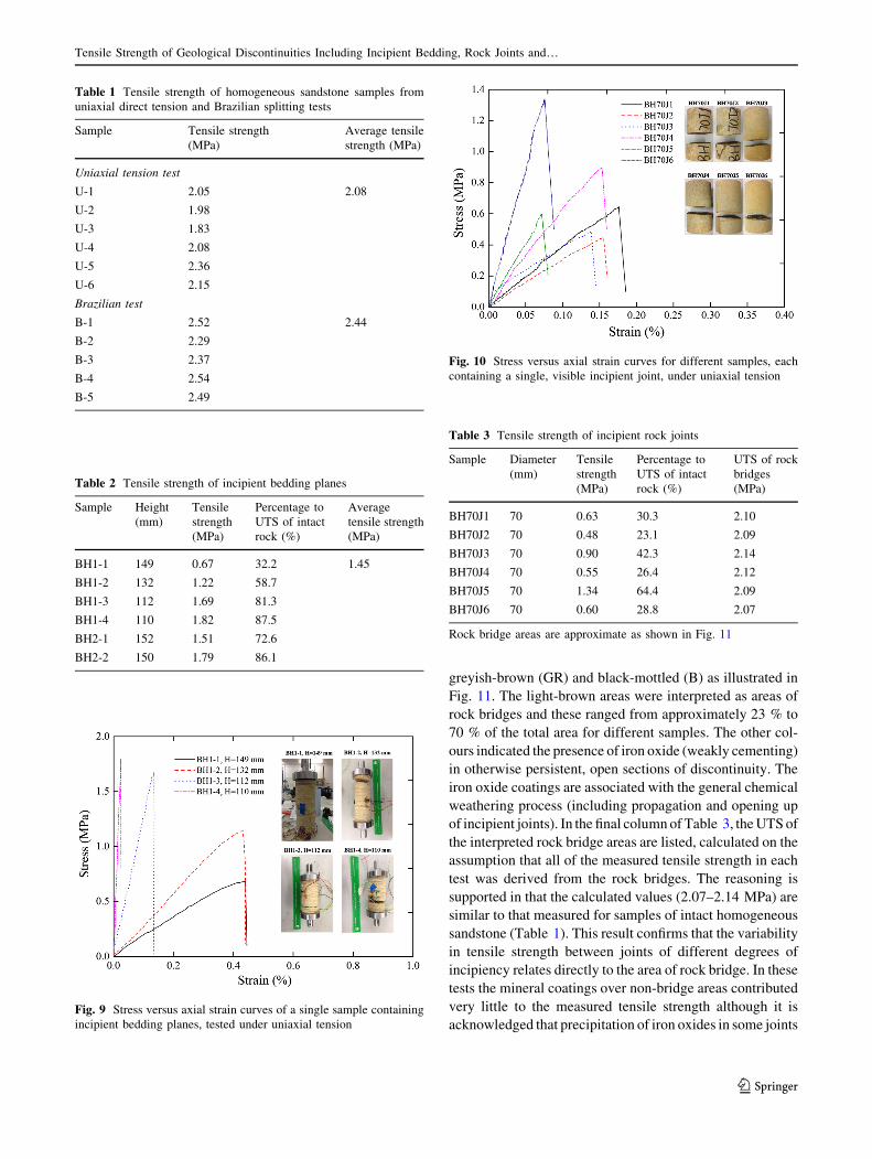
4.2 Samples with Incipient Joints
Direct tension tests were conducted on samples of osten-
sibly homogeneous of Blackhill sandstone containing
incipient joints, with the samples drilled so that the joints
were approximately orthogonal to the tensile force. Stress
versus axial strain curves are presented in Fig. 10. The
inset photographs illustrate that failure always occurred
along the incipient joint planes. All six samples with
incipient joints underwent brittle failure at a relatively low
axial strain (0.05–0.2 %) compared to some of the tests on
incipient bedding planes (Fig. 9). Table 3 shows that UTS
values for these incipient joints varied from 0.48 MPa
(sample BH70J2) to 1.34 MPa (sample BH70J5).
The joint surfaces were described using a four-colour
classification: light-brown (LB), reddish-brown (RB),
Fig. 7 Micro-strain vs time curves for verification tests for uniaxial
tension set-up. Four strain gauges were affixed as shown on the
diagram
Fig. 8 Fracture initiation and propagation within an intact sandstone sample during a Brazilian tension test. Loading was applied horizontally
relative to the photographs, which were taken using a high-speed camera (numbers are seconds from test initiation)
J. Shang et al.
123
greyish-brown (GR) and black-mottled (B) as illustrated in
Fig. 11. The light-brown areas were interpreted as areas of
rock bridges and these ranged from approximately 23 % to
70 % of the total area for different samples. The other col-
ours indicated the presence of iron oxide (weakly cementing)
in otherwise persistent, open sections of discontinuity. The
iron oxide coatings are associated with the general chemical
weathering process (including propagation and opening up
of incipient joints). In the final columnof Table 3, theUTSof
the interpreted rock bridge areas are listed, calculated on the
assumption that all of the measured tensile strength in each
test was derived from the rock bridges. The reasoning is
supported in that the calculated values (2.07–2.14 MPa) are
similar to that measured for samples of intact homogeneous
sandstone (Table 1). This result confirms that the variability
in tensile strength between joints of different degrees of
incipiency relates directly to the area of rock bridge. In these
tests the mineral coatings over non-bridge areas contributed
very little to the measured tensile strength although it is
acknowledged that precipitation of iron oxides in some joints
Table 1 Tensile strength of homogeneous sandstone samples from
uniaxial direct tension and Brazilian splitting tests
Sample Tensile strength
(MPa)
Average tensile
strength (MPa)
Uniaxial tension test
U-1 2.05 2.08
U-2 1.98
U-3 1.83
U-4 2.08
U-5 2.36
U-6 2.15
Brazilian test
B-1 2.52 2.44
B-2 2.29
B-3 2.37
B-4 2.54
B-5 2.49
Table 2 Tensile strength of incipient bedding planes
Sample Height
(mm)
Tensile
strength
(MPa)
Percentage to
UTS of intact
rock (%)
Average
tensile strength
(MPa)
BH1-1 149 0.67 32.2 1.45
BH1-2 132 1.22 58.7
BH1-3 112 1.69 81.3
BH1-4 110 1.82 87.5
BH2-1 152 1.51 72.6
BH2-2 150 1.79 86.1
Fig. 9 Stress versus axial strain curves of a single sample containing
incipient bedding planes, tested under uniaxial tension
Fig. 10 Stress versus axial strain curves for different samples, each
containing a single, visible incipient joint, under uniaxial tension
Table 3 Tensile strength of incipient rock joints
Sample Diameter
(mm)
Tensile
strength
(MPa)
Percentage to
UTS of intact
rock (%)
UTS of rock
bridges
(MPa)
BH70J1 70 0.63 30.3 2.10
BH70J2 70 0.48 23.1 2.09
BH70J3 70 0.90 42.3 2.14
BH70J4 70 0.55 26.4 2.12
BH70J5 70 1.34 64.4 2.09
BH70J6 70 0.60 28.8 2.07
Rock bridge areas are approximate as shown in Fig. 11
Tensile Strength of Geological Discontinuities Including Incipient Bedding, Rock Joints and…
123
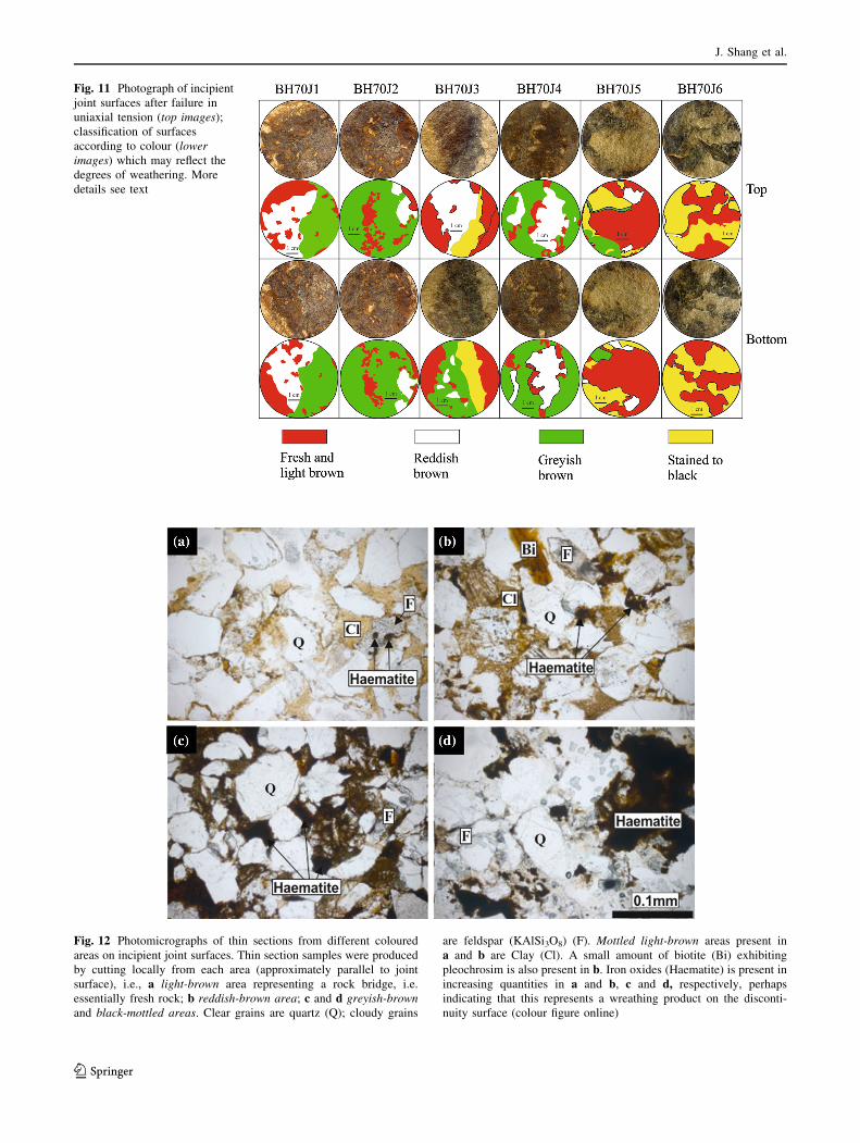
Fig. 12 Photomicrographs of thin sections from different coloured
areas on incipient joint surfaces. Thin section samples were produced
by cutting locally from each area (approximately parallel to joint
surface), i.e., a light-brown area representing a rock bridge, i.e.
essentially fresh rock; b reddish-brown area; c and d greyish-brown
and black-mottled areas. Clear grains are quartz (Q); cloudy grains
are feldspar (KAlSi3O8) (F). Mottled light-brown areas present in
a and b are Clay (Cl). A small amount of biotite (Bi) exhibiting
pleochrosim is also present in b. Iron oxides (Haematite) is present in
increasing quantities in a and b, c and d, respectively, perhaps
indicating that this represents a wreathing product on the disconti-
nuity surface (colour figure online)
Fig. 11 Photograph of incipient
joint surfaces after failure in
uniaxial tension (top images);
classification of surfaces
according to colour (lower
images) which may reflect the
degrees of weathering. More
details see text
J. Shang et al.
123
can sometimes lead to significantly increased tensile and
shear strength (Tating et al. 2015).
Petrographic thin sections were taken from variously
coloured areas on the joint surfaces to investigate miner-
alogy. Figure 12a shows an area interpreted as part of a
rock bridge in relatively fresh rock. Figure 12b, d is for
progressively darker coloured areas of joint surface. The
increase in quantity of iron oxide minerals from Fig. 12a–d
is considered indicative of degree of weathering although it
is acknowledged that such discoloration is currently diffi-
cult to quantify and link to rate of weathering as discussed
by Turkington and Paradise (2005).
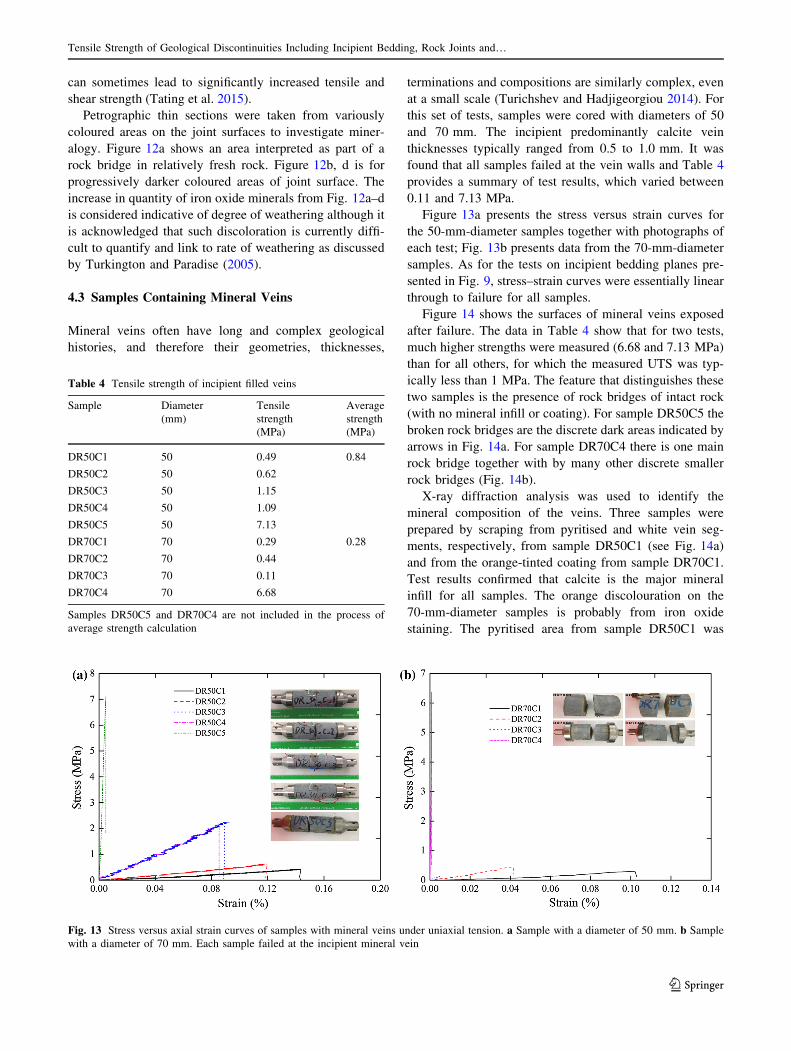
4.3 Samples Containing Mineral Veins
Mineral veins often have long and complex geological
histories, and therefore their geometries, thicknesses,
terminations and compositions are similarly complex, even
at a small scale (Turichshev and Hadjigeorgiou 2014). For
this set of tests, samples were cored with diameters of 50
and 70 mm. The incipient predominantly calcite vein
thicknesses typically ranged from 0.5 to 1.0 mm. It was
found that all samples failed at the vein walls and Table 4
provides a summary of test results, which varied between
0.11 and 7.13 MPa.
Figure 13a presents the stress versus strain curves for
the 50-mm-diameter samples together with photographs of
each test; Fig. 13b presents data from the 70-mm-diameter
samples. As for the tests on incipient bedding planes pre-
sented in Fig. 9, stress–strain curves were essentially linear
through to failure for all samples.
Figure 14 shows the surfaces of mineral veins exposed
after failure. The data in Table 4 show that for two tests,
much higher strengths were measured (6.68 and 7.13 MPa)
than for all others, for which the measured UTS was typ-
ically less than 1 MPa. The feature that distinguishes these
two samples is the presence of rock bridges of intact rock
(with no mineral infill or coating). For sample DR50C5 the
broken rock bridges are the discrete dark areas indicated by
arrows in Fig. 14a. For sample DR70C4 there is one main
rock bridge together with by many other discrete smaller
rock bridges (Fig. 14b).
X-ray diffraction analysis was used to identify the
mineral composition of the veins. Three samples were
prepared by scraping from pyritised and white vein seg-
ments, respectively, from sample DR50C1 (see Fig. 14a)
and from the orange-tinted coating from sample DR70C1.
Test results confirmed that calcite is the major mineral
infill for all samples. The orange discolouration on the
70-mm-diameter samples is probably from iron oxide
staining. The pyritised area from sample DR50C1 was
Table 4 Tensile strength of incipient filled veins
Sample Diameter
(mm)
Tensile
strength
(MPa)
Average
strength
(MPa)
DR50C1 50 0.49 0.84
DR50C2 50 0.62
DR50C3 50 1.15
DR50C4 50 1.09
DR50C5 50 7.13
DR70C1 70 0.29 0.28
DR70C2 70 0.44
DR70C3 70 0.11
DR70C4 70 6.68
Samples DR50C5 and DR70C4 are not included in the process of
average strength calculation
Fig. 13 Stress versus axial strain curves of samples with mineral veins under uniaxial tension. a Sample with a diameter of 50 mm. b Sample
with a diameter of 70 mm. Each sample failed at the incipient mineral vein
Tensile Strength of Geological Discontinuities Including Incipient Bedding, Rock Joints and…
123
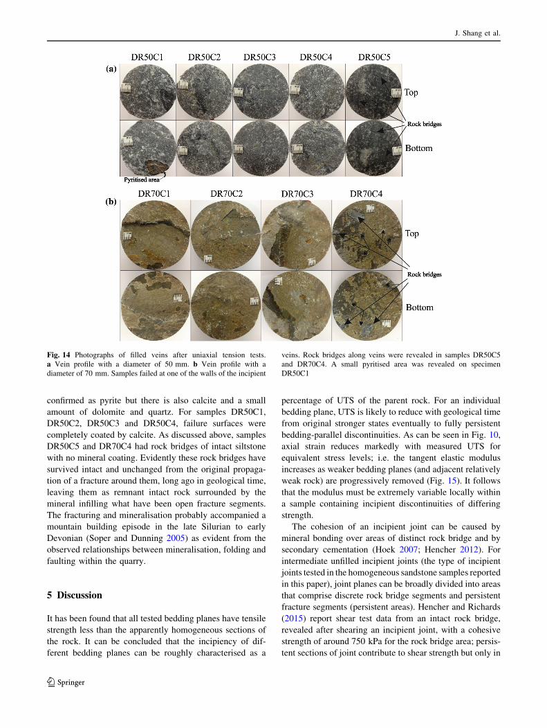
confirmed as pyrite but there is also calcite and a small
amount of dolomite and quartz. For samples DR50C1,
DR50C2, DR50C3 and DR50C4, failure surfaces were
completely coated by calcite. As discussed above, samples
DR50C5 and DR70C4 had rock bridges of intact siltstone
with no mineral coating. Evidently these rock bridges have
survived intact and unchanged from the original propaga-
tion of a fracture around them, long ago in geological time,
leaving them as remnant intact rock surrounded by the
mineral infilling what have been open fracture segments.
The fracturing and mineralisation probably accompanied a
mountain building episode in the late Silurian to early
Devonian (Soper and Dunning 2005) as evident from the
observed relationships between mineralisation, folding and
faulting within the quarry.
5 Discussion
It has been found that all tested bedding planes have tensile
strength less than the apparently homogeneous sections of
the rock. It can be concluded that the incipiency of dif-
ferent bedding planes can be roughly characterised as a
percentage of UTS of the parent rock. For an individual
bedding plane, UTS is likely to reduce with geological time
from original stronger states eventually to fully persistent
bedding-parallel discontinuities. As can be seen in Fig. 10,
axial strain reduces markedly with measured UTS for
equivalent stress levels; i.e. the tangent elastic modulus
increases as weaker bedding planes (and adjacent relatively
weak rock) are progressively removed (Fig. 15). It follows
that the modulus must be extremely variable locally within
a sample containing incipient discontinuities of differing
strength.
The cohesion of an incipient joint can be caused by
mineral bonding over areas of distinct rock bridge and by
secondary cementation (Hoek 2007; Hencher 2012). For
intermediate unfilled incipient joints (the type of incipient
joints tested in the homogeneous sandstone samples reported
in this paper), joint planes can be broadly divided into areas
that comprise discrete rock bridge segments and persistent
fracture segments (persistent areas). Hencher and Richards
(2015) report shear test data from an intact rock bridge,
revealed after shearing an incipient joint, with a cohesive
strength of around 750 kPa for the rock bridge area; persis-
tent sections of joint contribute to shear strength but only in
Fig. 14 Photographs of filled veins after uniaxial tension tests.
a Vein profile with a diameter of 50 mm. b Vein profile with a
diameter of 70 mm. Samples failed at one of the walls of the incipient
veins. Rock bridges along veins were revealed in samples DR50C5
and DR70C4. A small pyritised area was revealed on specimen
DR50C1
J. Shang et al.
123
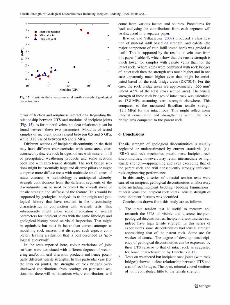
terms of friction and roughness interactions. Regarding the
relationship between UTS and modulus of incipient joints
(Fig. 15), as for mineral veins, no clear relationship can be
found between these two parameters. Modulus of tested
samples of incipient joints ranged between 0.5 and 5 GPa,
while UTS varied between 0.5 and 2 MPa.
Different sections of incipient discontinuity in the field
may have different characteristics with some areas char-
acterised by discrete rock bridges, others with mineral infill
or precipitated weathering products and some sections
open and with zero tensile strength. The rock bridge sec-
tions might be essentially large and discrete pillars or might
comprise more diffuse areas with multitude small zones of
intact contacts. A methodology is anticipated whereby
strength contributions from the different segments of the
discontinuity can be used to predict the overall shear or
tensile strength and stiffness of the feature. This would be
supported by geological analysis as to the origin and geo-
logical history that have resulted in the discontinuity
characteristics in conjunction with strength tests. This
subsequently might allow some predication of overall
parameters for incipient joints with the same lithology and
geological history based on visual inspection. That might
be optimistic but must be better than current attempts at
modelling rock masses that disregard such aspects com-
pletely leaving a situation that is best described as ‘geo-
logical guesswork’.
In the tests reported here, colour variations of joint
surfaces were associated with different degrees of weath-
ering and/or mineral alteration products and hence poten-
tially different tensile strengths. In this particular case (for
the tests on joints), the strengths of rock bridges over-
shadowed contributions from coatings on persistent sec-
tions but there will be situations where contributions will
come from various factors and sources. Procedures for
back-analysing the contributions from each segment will
be discussed in a separate paper.
Brzovic and Villaescusa (2007) produced a classifica-
tion of mineral infill based on strength, and calcite (the
major component of vein infill tested here) was graded as
‘soft’. This is supported by the results of vein tests from
this paper (Table 4), which show that the tensile strength is
much lower for samples with calcite veins than for the
intact rock. Where veins were combined with rock bridges
of intact rock then the strength was much higher and in one
case apparently much higher even than might be antici-
pated based on the rock bridge areas (DR70C4). For this
case, the rock bridge areas are approximately 1555 mm2
(about 42 % of the total cross section area). The tensile
strength of these rock bridges of intact rock was calculated
as 17.8 MPa assuming zero strength elsewhere. This
compares to the measured Brazilian tensile strength
(12.5 MPa) for the intact rock. This might reflect some
internal cementation and strengthening within the rock
bridge area compared to the parent rock.
6 Conclusions
Tensile strength of geological discontinuities is usually
neglected or underestimated by current standards (e.g.
ISRM) and rock mechanics practitioners. Incipient rock
discontinuities, however, may retain intermediate or high
tensile strength—approaching and even exceeding that of
the parent rock and will consequently strongly influence
rock-engineering performance.
In this study, a series of uniaxial tension tests were
carried on incipient geological discontinuities at laboratory
scale including incipient bedding (bedding laminations),
mineral veins and incipient rock joints. Tensile strength of
these incipient features was identified.
Conclusions drawn from this study are as follows:
1. The direct tension test is useful to measure and
research the UTS of visible and discrete incipient
geological discontinuities. Incipient discontinuities can
indeed have high tensile strength. In this series of
experiments some discontinuities had tensile strength
approaching that of the parent rock. Some are far
weaker of course. The degree of development/incipi-
ency of geological discontinuities can be expressed by
their UTS relative to that of intact rock as suggested
for broad characterisation by Hencher (2015).
2. Tests on weathered but incipient rock joints (with rock
bridges) showed a clear relationship between UTS and
area of rock bridges. The open, mineral coated sections
of joint contributed little to the tensile strength.
Fig. 15 Elastic modulus versus uniaxial tensile strength of geological
discontinuities
Tensile Strength of Geological Discontinuities Including Incipient Bedding, Rock Joints and…
123
3. For tests on calcite veins the UTS was considerably
lower than that of the intact rock. Where rock bridges
were present as well as mineral infill, then the rock
bridge strength dominated measured strength.
4. Sandstone samples containing incipient geological
fractures always break through these weaker planes
under direct tension. Geological discontinuities tested
in this paper all exhibited brittle failure after direct
tension at a low axial strain below 0.5 %.
5. The tangent elastic modulus increases as weaker
bedding planes are progressively removed, i.e. the
higher strength, the higher modulus. For mineral veins
and incipient joints, however, no clear relations can be
established between UTS and modulus.
Acknowledgments The China Scholarship Council and the Univer-
sity of Leeds provided financial support to this research. The support
and practical assistance of the managers of Dry Rigg Quarry and
Blackhill Quarry is gratefully acknowledged. Kirk Handley and John
Martin are thanked for their support and constructive suggestions
regarding the laboratory testing at the University of Leeds.
Open Access This article is distributed under the terms of the
Creative Commons Attribution 4.0 International License (http://crea
tivecommons.org/licenses/by/4.0/), which permits unrestricted use,
distribution, and reproduction in any medium, provided you give
appropriate credit to the original author(s) and the source, provide a
link to the Creative Commons license, and indicate if changes were
made.
References
Aitkenhead N, Barclay WJ, Brandon A, Chadwick RA, Chisholm JI,
Cooper AH, Johnson EW (2002) The Pennines and adjacent
areas, 4th edn. British Geological Survey, Nottingham, pp 8–14
Arthurton RS, Johnson EW, Mundy DJC (1988) Geology of the
country around Settle. Memoir of the British Geological Survey,
Sheet 60 (English and Wales)
Barla G, Innaurato N (1973) Indirect tensile testing of anisotropic
rocks. Rock Mech Rock Eng 5:215–230
Brzovic A, Villaescusa E (2007) Rock mass characterization and
assessment of block-forming geological discontinuities during
caving of primary copper ore at the EI Teniente mine, Chile. Int
J Rock Mech Min Sci 44:565–583
Cravero M, Iabichino G (2004) Analysis of the flexural failure of an
overhanging rock slab. Int J Rock Mech Min Sci 41(3):605–610
Dan DQ, Konietzky H, Herbst M (2013) Brazilian tensile strength
tests on some anisotropic rocks. Int J Rock Mech Min Sci 58:1–7
Deere DU (1968) Geological considerations. Chapter 1. In: Stagg KG,
Zienkiewicz OC (eds) Rock mechanics in engineering practice.
Wiley, New York, pp 1–20
Deere DU, Deere DW (1989) Rock quality designation (RQD) after
twenty years. Contract Report GL-89-1, US Army Corps of
Engineers, 67p plus Appendix
Erarslan N, Williams DJ (2012) Experimental, numerical and
analytical studies on tensile strength of rocks. Int J Rock Mech
Min Sci 49:21–30
Hashiba K, Fukui K (2014) Effect of water on the deformation and
failure of rock in uniaxial tension. Rock Mech Rock Eng
47:1–11
Hawkes I, Mellor M, Gariepy S (1973) Deformation of rocks under
uniaxial tension. Int J Rock Mech Min Sci Geomech Abstr
10:493–507
Hencher SR (2006) Weathering and erosion processes in rock –
implications for geotechnical engineering. In: Proceedings
symposium on Hong Kong soils and rocks, March 2004.
Institution of Mining, Metallurgy and Materials and Geological
Society of London, pp 29–79
Hencher SR (2012) Practical engineering geology. Spon Press, Taylor
& Francis, Oxon
Hencher SR (2014) Characterizing discontinuities in naturally
fractured outcrop analogues and rock core: the need to consider
fracture development over geological time. Geol Soc Lond Spec
Publ Adv Study Fract Reserv 374:113–123
Hencher SR (2015) Practical rock mechanics. Spon Press, Taylor and
Francis, Oxon
Hencher SR, Knipe R (2007) Development of rock joints with time
and consequences for engineering. In: Proceeding of the 11th
congress of the international society of rock mechanics, Lisbon,
Portugal
Hencher SR, Richards LR (2015) Assessing the shear strength of rock
discontinuities at laboratory and field scales. Rock Mech Rock
Eng 48:883–905
Hoek E (2007) Practical rock engineering. p 342. http://www.
rocscience.com
ISRM (1978a) Suggested methods for the quantitative description of
discontinuities in rock masses. Int J Rock Mech Min Sci
Geomech Abstr 15:319–368
ISRM (1978b) Suggested methods for determining tensile strength of
rock materials. Int J Rock Mech Min Sci Geomech Abstr
15:99–103
Khan AS, Irani FK (1987) An experimental study of stress wave
transmission at a metallic-rock interface and dynamic tensile
failure of sandstone, limestone and granite. Mech Mater
6:285–292
King WBR (1934) The lower palaeozoic rocks of Austwick and
Horton-in-Ribblesdale, Yorkshire. Q J Geol Soc Lond 90:7–31
Kwansniewski M (2009) Testing and modelling of the anisotropy of
tensile strength of rocks. Proceeding of the international
conference on rock joints and jointed rock masses Arizona,
United States
Li HB, Li JC, Bo L, Li JR, Li SQ, Xia X (2013) Direct tension test for
rock material under different strain rates at quasi-static loads.
Rock Mech Rock Eng 46:1247–1254
Liao JJ, Yang MT, Hsieh HY (1997) Direct tensile behaviour of a
transversely isotropic rock. Int J Rock Mech Min Sci
34(5):837–849
Liu JF, Chen L, Wang C, Man K, Wang L, Wang J, Su R (2014)
Characterizing the mechanical tensile behaviour of Beishan
granite with different experimental methods. Int J Rock Mech
Min Sci 69:50–58
Mier JGM, Shi C (2002) Stability issues in uniaxial tensile tests on
brittle disordered materials. Int J Solids Struct 39:3359–3372
Okubo S, Fukui K (1996) Complete stress-strain curves for various
rock types in uniaxial tension. Int J Rock Mech Min Sci
33(6):549–556
Paronuzzi P, Serafini W (2009) Stress state analysis of a collapsed
overhanging rock slab: a case study. Eng Geol 108:65–75
Pells PJN (1993) Uniaxial strength testing. In: Hudson JA (ed)
Comprehensive rock engineering, vol 3. Pergamon Press, Exeter,
pp 67–85
Perras MA, Diederichs M (2014) A review of the tensile strength of
rock: concepts and testing. Geotech Geol Eng 32:525–546
Saiang D, Malmgren L, Nodlund E (2005) Laboratory tests on
shotcrete–rock joints in direct shear, tension and compression.
Rock Mech Rock Eng 38(4):275–297
J. Shang et al.
123
Soper NJ, Dunning FW (2005) Structure and sequence of the Ingleton
Group, basement to the central Pennines of northern England.
Proc Yorks Geol Soc 55:241–261
Stevenson IP, Gaunt GD (1971) Geology of the country around
Chapel-en-le-Frith. Memoir of the Geological Survey of Great
Britain, Sheet 99 (English and Wales)
Tating F, Hack R, Jetten V (2015) Weathering effects on disconti-
nuity properties in sandstone in a tropical environment: case
study at Kota Kinabalu, Sabah Malaysia. Bull Eng Geol Environ
74:427–441
Turichshev A, Hadjigeorgiou J (2014) Experimental and numerical
investigations into the strength of intact veined rock. Rock Mech
Rock Eng 48:1897–1912
Turkington AV, Paradise TR (2005) Sandstone weathering: a century
of research and innovation. Geomorphology 67:229–253
Wang W (2009) Rock mass mechanics (English edition). Central
South University Press, Changsha
Waters CN, Aitkenhead N, Jones NS, Chisholm JI (1996) Late
Carboniferous stratigraphy and sedimentology of the Bradford
area, and its implications for the regional geology of northern
England. Proceeding of the Yorkshire Geological Society
51(Part 2):87–101
Tensile Strength of Geological Discontinuities Including Incipient Bedding, Rock Joints and…
123
Recommended