Synthesis of Textures with Intricate Geometries using BTF and Large Number ofTextured Micropolygons
sub047
Abstract
BTF has been studied extensively and much progress hasbeen done for measurements, compression and renderingso far. However, with regard to representation of materi-als with intricate geometries such as furs, carpets or tow-els, many problems still remain. For example, complicatedsilhouettes of such materials are difficult to represent byBTF. Another problem is synthesis of BTF to arbitrary tex-ture size. In this paper, we propose a method to synthe-size and render objects, applying textures of such materials.Small-scaled geometries produce unique visual patterns onactual textures and produce complicated silhouettes. In themethod, we draw a large number of small-sized polygonsplaced on the shape model, with visual patterns and silhou-ettes represented by alpha-channeled images mapped on thepolygons as textures. The images are sampled from smallpieces of the materials with various view directions. Usingthe proposed method, we can synthesize the patterns and sil-houettes caused by small-scaled geometries. The final im-ages are produced by compositing the visual patterns witha textures rendered by BTF, which can realize the effects ofanisotropic reflections of the texture.
1. IntroductionThe modeling and rendering of materials such as furs, car-pets and towels which have intricate geometrical structuresare challenging and important problems in the field of com-puter graphics. Since such complex geometries are difficultto model with polygon meshes, many methods have beenresearched. Although many effective methods such as us-ing particles have been proposed, most of them still requirehigh skills and a lot of time. Moreover, such materials tendsto have complex, anisotropic reflection properties makingthe problem more difficult.
One potential solution for this purpose is sampling BTFfrom real materials. However, there remains some prob-lems. Sampling BTF requires a special sampling equip-ment, and sampled BTF data tend to be enormous even ifcompressed by recently proposed methods. Moreover, itcannot represent complex silhouettes caused by intricate ge-ometries of such materials; note that intricate geometriesproduce not only complex silhouettes, but also many other
visual effects such as hair strand patterns, etc. Another typ-ical problem is seamless tiling of textures.
In this paper, a novel method for rendering arbitraryshaped objects, applying materials with intricate geometriessuch as furs are proposed. Normally, intricate geometriescause unique visual patterns to their appearances. For ex-ample, furs exhibits numerous stripe patterns along the di-rection of the hair strands. In the proposed method, visualpattens caused by intricate geometries are synthesized asa collection of small images sampled from a piece of thematerial. The visual patterns are combined with anotherimage which is synthesized using low-pass filtered BTF,which expresses the effects of reflectance such as shadingsor speculars. The advantages of the proposed method are:(1) since the method is based on sampling, modeling of in-tricate geometries is not necessary, (2) by using low-passfiltered BTF, quantity of the texture data is greatly reduced,(3) by using low-pass filtered BTF, anisotropic reflectionproperties can be synthesized, and (4) visual pattens and ef-fects of silhouettes caused by intricate geometries can berendered.
2. Related studiesRendering and modeling fur, knit fabrics, hair and other in-tricate geometry and small structures of objects has beeninvestigated extensively [?, ?, ?]. Lengyel et al. [?] usedshell texture to render volumetric fur and fins to render thesilhouettes of fur in real time.
Relatively small geometry, such as the surface of a car-pet or clothing, is often represented using the bi-directionaltexture function (BTF). Since BTFs are effective to rendermaterials realistically, efficient representations and render-ing techniques have been intensively studied, such as poly-nomial texture maps (PTM) [?], Spherical harmonics (SH)representation [?], Precompiled radiance transfer (PRT)[?],bi-scale radiance transfer (BRT) [?]. or factorization-basedmethods [?].
Point-based approaches have also been applied in tomodel and render such mesoscopic geometry. For exam-ple, for the rendering of trees, Meyer [?] rendered com-plex repetitive scenes using a volume renderer with view-dependent texture, which switches textures according to theview direction. Max [?] used layered depth images to ren-
1
Micropolygons
Surface
Textures
ViewpointMapping
Sampling points
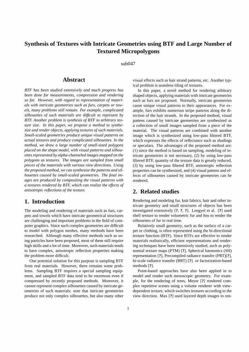
Figure 1: Representation of small-scaled geometry.
der trees. Yamazaki et al. [?] used billboarding microfacetstextured with real images to render fur. Reche [?] extendedYamazaki’s method and successfully rendered trees from anumber of images.
Our method to render visual patterns caused by complexgeometries as a collection of small images is inspired bythe Yamazaki’s method. Their work and ours have differentpurposes; the purpose of their work is to replay the appear-ance of the sampled object as it is, and the purpose of oursis to apply sampled material to arbitrary surface model.
3. Overview of rendering stepsIn our method, two different types of rendering are appliedto express visual effects caused by different scales of ge-ometries. The effects caused by the smaller scaled geome-tries are visual patterns of intricate geometries of the ma-terial. These patterns are expressed by a large number ofsmall images arranged at a point set sampled from the sur-face of the rendered shape. The effects caused by the largerscaled geometries are shadings and speculars, which arechanged by the directions of the surface of the model, thelight directions and the view direction. These effects are ex-pressed by low-resolution BTFs, which are BTFs processedby a low-pass filter about texture coordinates. Final imagesare synthesized by compositing those two kind of images.
First, the method to synthesize visual effects of intricategeometries are explained. As already mentioned, the ef-fects are rendered by drawing collection of images. Theseimages are appearances of a piece of the material called a“material unit,” which can be seen as an unit of the visualpatterns. To express overlapping effects between the pat-terns (for example, adjacent strands of a fur look overlappedeach other, causing self-occlusions), these arranged imagesinclude the alpha channel which represents the transparencyof each pixel. By the overlapping images with effects oftransparency, the appearance of the surface covered by theintricate geometries are expressed. In this paper, drawing ofthe images are realized by drawing a large number of tex-tured, small-sized polygons (micropolygons). Polygons arelocated at a set of points, sampled from the rendered sur-face. Those points are called “sampling points.” Figure 1
shows the basic idea of the method.Complex silhouettes caused by intricate geometries are
also synthesized with the same process. Since the trans-parency is applied, the geometrical silhouettes are renderedas the border of the pattens in the images drawn near theedges of the rendered shape.
Then, the effects of shadings and speculars which ex-hibits anisotropic reflection properties are rendered inde-pendently. It can be achieved by applying low-pass filter-ing about texture coordinates on BTFs. The shape model isrendered for designated view and the lighting conditions byapplying the same method proposed by Furukawa et al.[?].In the rendered image, the effects of the shadings and thespeculars are represented.
At the final stage of rendering, the visual patterns and theresult of BTF rendering are composited. For the composi-tion method, several formulation can be considered. Onesimple method is just multiplying the two rendering results.Another effective method is more complicated is as follows;the BTF rendering is done first, and, when the micropoly-gons are drawn to express visual patterns, the color of eachmicropolygon is modulated by using the result of BTF ren-dering.
4. Implementation4.1. Sampling appearances of intricate geome-
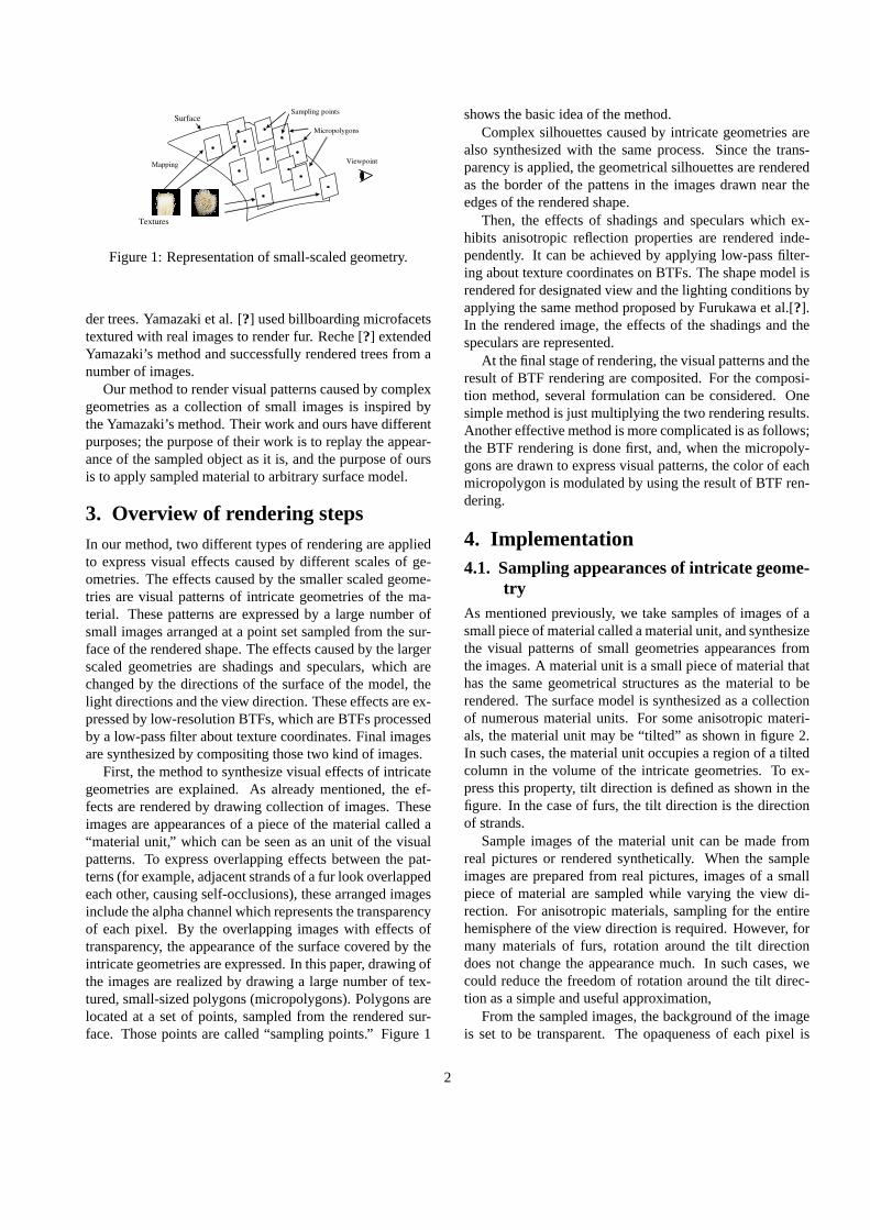
tryAs mentioned previously, we take samples of images of asmall piece of material called a material unit, and synthesizethe visual patterns of small geometries appearances fromthe images. A material unit is a small piece of material thathas the same geometrical structures as the material to berendered. The surface model is synthesized as a collectionof numerous material units. For some anisotropic materi-als, the material unit may be “tilted” as shown in figure 2.In such cases, the material unit occupies a region of a tiltedcolumn in the volume of the intricate geometries. To ex-press this property, tilt direction is defined as shown in thefigure. In the case of furs, the tilt direction is the directionof strands.
Sample images of the material unit can be made fromreal pictures or rendered synthetically. When the sampleimages are prepared from real pictures, images of a smallpiece of material are sampled while varying the view di-rection. For anisotropic materials, sampling for the entirehemisphere of the view direction is required. However, formany materials of furs, rotation around the tilt directiondoes not change the appearance much. In such cases, wecould reduce the freedom of rotation around the tilt direc-tion as a simple and useful approximation,
From the sampled images, the background of the imageis set to be transparent. The opaqueness of each pixel is
2
Material unit
Tilt direction
Volume of the material
(a) (b) (c)
Figure 2: Tilted material unit: (a) a material unit and itstilt direction, (b) material units arranged in a volume of thematerial, (c) an example of a tilted material unit.
Viewpoint
Occlusion
Renderingorder
Surface
Materialunits
Viewpoint
Surface
Micropolygonstilted along
tilt directions.
Micropolygonsdirectedwith
exceptional rules
(a) (b)
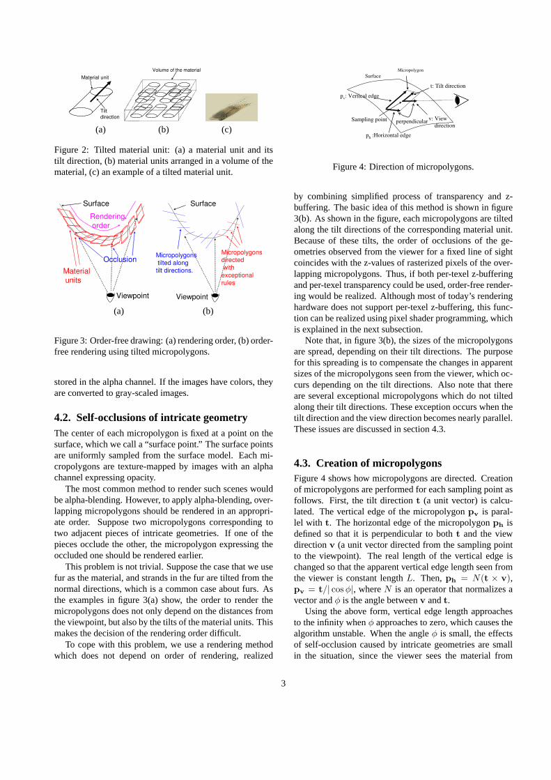
Figure 3: Order-free drawing: (a) rendering order, (b) order-free rendering using tilted micropolygons.
stored in the alpha channel. If the images have colors, theyare converted to gray-scaled images.
4.2. Self-occlusions of intricate geometryThe center of each micropolygon is fixed at a point on thesurface, which we call a “surface point.” The surface pointsare uniformly sampled from the surface model. Each mi-cropolygons are texture-mapped by images with an alphachannel expressing opacity.
The most common method to render such scenes wouldbe alpha-blending. However, to apply alpha-blending, over-lapping micropolygons should be rendered in an appropri-ate order. Suppose two micropolygons corresponding totwo adjacent pieces of intricate geometries. If one of thepieces occlude the other, the micropolygon expressing theoccluded one should be rendered earlier.
This problem is not trivial. Suppose the case that we usefur as the material, and strands in the fur are tilted from thenormal directions, which is a common case about furs. Asthe examples in figure 3(a) show, the order to render themicropolygons does not only depend on the distances fromthe viewpoint, but also by the tilts of the material units. Thismakes the decision of the rendering order difficult.
To cope with this problem, we use a rendering methodwhich does not depend on order of rendering, realized
v: Viewdirection
MicropolygonSurface
t: Tilt direction
Sampling point
ph :Horizontal edge
pv: Vertical edge
perpendicular
Figure 4: Direction of micropolygons.
by combining simplified process of transparency and z-buffering. The basic idea of this method is shown in figure3(b). As shown in the figure, each micropolygons are tiltedalong the tilt directions of the corresponding material unit.Because of these tilts, the order of occlusions of the ge-ometries observed from the viewer for a fixed line of sightcoincides with the z-values of rasterized pixels of the over-lapping micropolygons. Thus, if both per-texel z-bufferingand per-texel transparency could be used, order-free render-ing would be realized. Although most of today’s renderinghardware does not support per-texel z-buffering, this func-tion can be realized using pixel shader programming, whichis explained in the next subsection.
Note that, in figure 3(b), the sizes of the micropolygonsare spread, depending on their tilt directions. The purposefor this spreading is to compensate the changes in apparentsizes of the micropolygons seen from the viewer, which oc-curs depending on the tilt directions. Also note that thereare several exceptional micropolygons which do not tiltedalong their tilt directions. These exception occurs when thetilt direction and the view direction becomes nearly parallel.These issues are discussed in section 4.3.
4.3. Creation of micropolygonsFigure 4 shows how micropolygons are directed. Creationof micropolygons are performed for each sampling point asfollows. First, the tilt directiont (a unit vector) is calcu-lated. The vertical edge of the micropolygonpv is paral-lel with t. The horizontal edge of the micropolygonph isdefined so that it is perpendicular to botht and the viewdirectionv (a unit vector directed from the sampling pointto the viewpoint). The real length of the vertical edge ischanged so that the apparent vertical edge length seen fromthe viewer is constant lengthL. Then,ph = N(t × v),pv = t/| cos φ|, whereN is an operator that normalizes avector andφ is the angle betweenv andt.
Using the above form, vertical edge length approachesto the infinity whenφ approaches to zero, which causes thealgorithm unstable. When the angleφ is small, the effectsof self-occlusion caused by intricate geometries are smallin the situation, since the viewer sees the material from
3
the tilt direction. Considering this fact we apply anothermethod to create the micropolygon when| cos φ| is less thana threshold value. The second rule is,ph = N(n × v),pv = N(v× ph), wheren is the outward normal directionof the surface at the sampling point. This rule means thatthe micropolygon is created so that it is perpendicular to theview directionv and the apparent direction of the normalnand the vertical edgepv is the same.
The sampled images for the material unit are used asthe textures of the micropolygons to represent visual ef-fects of small-scaled geometries. Selection of the texturemapped onto a micropolygon depends on the view direc-tion expressed in the tangent space at the surface point. Ifthe material is isotropic, the image sampled with the near-est latitude angle as the view direction is selected. If thematerial is anisotropic, the image sampled with the nearestdirection in the hemisphere as the view direction is selected.
4.4. Per-texel transparency using pixel shaders
Most of today’s rendering hardware does not support per-texel z-buffering as it is. Even using today’s pixel shaders,full-fledged alpha-blending and z-buffering cannot be im-plemented, since the frame buffer are not accessible fromthe pixel shaders. However, by giving up on general alpha-blending, and by simplifying the problem to the case that allthe texels are either completely transparency or completelyopacity, then, the rendering process can be programmed bypixel shaders.
The concrete method is as the following. The micropoly-gons are rendered as normally done with the z-buffering on.In the pixel shader program, the alpha value of the texel iscompared with a fixed threshold, for example 0.5. If the al-pha value of the texel is less than the threshold, the drawingof the pixel is canceled by ’cancel’ instruction, otherwise,the color of the pixel is updated using the texel value. Sincethe canceled pixel does not affect neither z-buffer or frame-buffer, per-texel z-buffering and per-texel transparency arerealized.
In the above method, all the texels are processed as com-pletely opacity or transparency. Since blending at the bor-ders between the overlapping micropolygons are not per-formed, those borders does not look natural. To alleviatethis problem, anti-aliasing the border by multi-path render-ing is effective.
This process can be done as the following. First, ren-dering is processed several times, changing the threshold ofalpha value to decide opacity or transparency (For example,rendering three times, changing the threshold to 0.4, 0.5 and0.6.). Then, the result image is synthesized by averagingthose rendered images for each pixel.
(a)
(b)
(c)
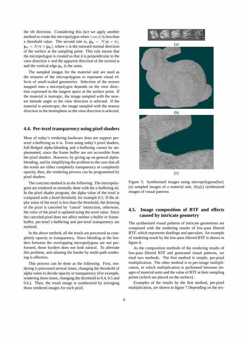
Figure 5: Synthesized images using micropolygons(fur):(a) sampled images of a material unit, (b),(c) synthesizedimages of visual patterns
4.5. Image composition of BTF and effectscaused by intricate geometry
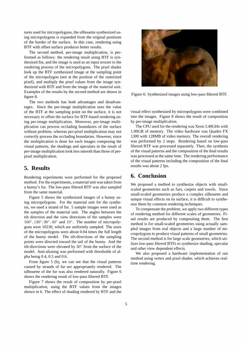
The synthesized visual patterns of intricate geometries arecomposed with the rendering results of low-pass filteredBTF, which represents shadings and speculars. An exampleof rendering result by the low-pass filtered BTF is shown infigure 6.
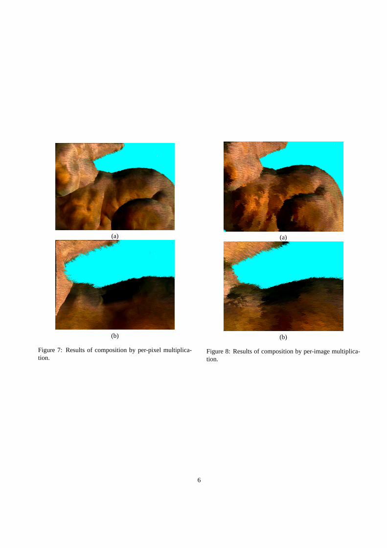
As the composition methods of the rendering results oflow-pass filtered BTF and generated visual patterns, wetried two methods. The first method is simple, per-pixelmultiplication. The other method is to per-image multipli-cation, in which multiplication is performed between im-ages of material units and the value of BTF at their samplingpoints (which are placed on the surface).
Examples of the results by the first method, per-pixelmultiplication, are shown in figure 7 Depending on the tex-
4
tures used for micropolygons, the silhouette synthesized us-ing micropolygons is expanded from the original positionsof the border of the surface. In this case, rendering usingBTF with offset surface produces better results.
The second method, per-image multiplication, is per-formed as follows: the rendering result using BTF is syn-thesized fist, and the image is used as an input texture to therendering process of the micropolygons. The pixel shaderlook up the BTF synthesized image at the sampling pointof the micropolygon (not at the position of the rasterizedpixel), and multiply the pixel values from the image syn-thesized with BTF and from the image of the material unit.Examples of the results by the second method are shown infigure 8.
The two methods has both advantages and disadvan-tages. Since the per-image multiplication uses the valueof the BTF at the sampling point on the surface, it is notnecessary to offset the surface for BTF-based rendering us-ing per-image multiplication. Moreover, per-image multi-plication can process occluding boundaries of the surfacewithout problem, whereas per-pixel multiplication may notcorrectly process the occluding boundaries. However, sincethe multiplication is done for each images composing thevisual patterns, the shadings and speculars in the result ofper-image multiplication look less smooth than those of per-pixel multiplication.
5. Results
Rendering experiments were performed for the proposedmethod. For the experiments, a material unit was taken froma bunny’s fur. The low-pass filtered BTF was also sampledfrom the same material.
Figure 5 shows the synthesized images of a bunny us-ing micropolygons. For the material unit for the synthe-sis, we used a strand of fur. 5 sample images were used asthe samples of the material unit. The angles between thetilt direction and the view directions of the samples were160◦, 130◦, 90◦, 40◦ and10◦. The number of micropoly-gons were 10230, which are uniformly sampled. The sizesof the micropolygons were about 0.04 times the full lengthof the bunny model. The tilt-directions of the samplingpoints were directed toward the tail of the bunny. And thetilt-directions were elevated by30◦ from the surface of themodel. Anti-aliasing was performed with thresholds of al-pha being 0.4, 0.5 and 0.6.
From figure 5 (b), we can see that the visual patternscaused by strands of fur are appropriately rendered. Thesilhouette of the fur was also rendered naturally. Figure 6shows the rendering result of low-pass filtered BTF.
Figure 7 shows the result of composition by per-pixelmultiplication, using the BTF values from the imagesshown in 6. The effect of shading rendered by BTF and the
Figure 6: Synthesized images using low-pass filtered BTF.
visual effect synthesized by micropolygons were combinedinto the images. Figure 8 shows the result of compositionby per-image multiplication.
The CPU used for the rendering was Xeon 3.40GHz with1.00GB of memory. The video hardware was Quadro FX1300 with 128MB of video memory. The overall renderingwas performed by 2 steps. Rendering based on low-passfiltered BTF was processed separately. Then, the synthesisof the visual patterns and the composition of the final resultswas processed at the same time. The rendering performanceof the visual patterns including the composition of the finalresults was about 2 fps.
6. ConclusionWe proposed a method to synthesize objects with small-scaled geometries such as furs, carpets and towels. Sincesmall-scaled geometries produce a complex silhouette andunique visual effects on its surface, it is difficult to synthe-size them by common rendering techniques.
To compensate the problem, we apply two different typesof rendering method for different scales of geometries. Fi-nal results are produced by compositing them. The firstmethod is for small-scaled geometries using actually sam-pled images from real objects and a large number of mi-cropolygons to produce visual patterns of small geometries.The second method is for large scale geometries, which uti-lizes low-pass filtered BTFs to synthesize shading, specularand other view dependent effects.
We also proposed a hardware implementation of ourmethod using vertex and pixel shader, which achieves real-time rendering.
5
(a)
(b)
Figure 7: Results of composition by per-pixel multiplica-tion.
(a)
(b)
Figure 8: Results of composition by per-image multiplica-tion.
6
Recommended