SupercriticalCarbonDioxideBraytonCycleEnergyConversionR&DWorkshop
September 11, 2014
Omni William Penn, 530 William Penn Place, Pittsburgh, Pennsylvania, USA
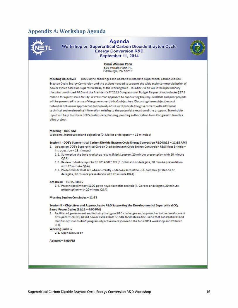
The objective of the meeting was to discuss the challenges and obstacles related to Supercritical Carbon Dioxide Brayton Cycle Energy Conversion and the actions needed to support the wide‐scale
commercialization of power cycles based on supercritical CO2 (SCO2) as the working fluid. This discussion will inform preliminary plans for continued research and development (R&D) and the President's Fiscal Year (FY) 2015 Congressional Budget Request that includes $27.5 million for a pilot‐scale facility. A
straw‐man approach to conducting the required R&D and pilot projects will be presented in terms of the government’s draft objectives. Discussing these objectives and potential options or approaches to these objectives will provide the government with additional technical and engineering information relating to the potential execution of the program. Stakeholder input will help to inform the U.S. Department of Energy’s (DOE) preliminary planning, pending authorization from the U.S. Congress to launch a pilot
project. This summary report was prepared by Leonardo Technologies Inc. (LTI) under contract NETL DE‐FE0004002 Task 300.02.09.
TableofContents
I. Session I – DOE’s Supercritical Carbon Dioxide Brayton Cycle Energy Conversion R&D ..... 1
Introduction .......................................................................................................................................... 1
Update on DOE’s Supercritical Carbon Dioxide Brayton Cycle Energy Conversion R&D ...................... 1
II. Session II – Objectives and Approaches to R&D Supporting the Development of Supercritical CO2 Based Power Cycles ............................................................................... 5
Objective 1: Size / Scale of Pilot Test Facility ........................................................................................ 8
Objective 2: Design Test Temperature (oC) ........................................................................................ 10
Objective 3: Heat Source .................................................................................................................... 12
Objective 4: Component Validation and Cycle Validation .................................................................. 13
Concluding Group Discussion / Remarks ............................................................................................ 15
Next Steps .......................................................................................................................................... 15
Appendix A: Workshop Agenda ............................................................................................. 16

Disclaimer This report was prepared as an account of work sponsored by an agency of the United States Government. Neither the United States Government nor any agency thereof, nor any of their employees, makes any warranty, express or implied, or assumes any legal liability or responsibility for the accuracy, completeness, or usefulness of any information, apparatus, product, or process disclosed, or represents that its use would not infringe privately owned rights. Reference therein to any specific commercial product, process, or service by trade name, trademark, manufacturer, or otherwise does not necessarily constitute or imply its endorsement, recommendation, or favoring by the United States Government or any agency thereof. The views and opinions of authors expressed herein do not necessarily state or reflect those of the United States Government or any agency thereof.
Supercritical Carbon Dioxide Brayton Cycle Energy Conversion R&D Workshop 1
I. SessionI–DOE’sSupercriticalCarbonDioxideBraytonCycleEnergyConversionR&D
Introduction
The 4th International Supercritical CO2 Power Cycles Symposium that occurred over the previous two days (September 9‐10, 2014) is evidence that there is interest and progress being made regarding supercritical carbon dioxide (SCO2) Brayton Cycle energy conversion research and development (R&D). There is enthusiasm within the U.S. Department of Energy (DOE) and U.S. Congress regarding SCO2 power cycles. The purpose of the workshop is to fact find and not drive consensus toward any particular option or approach listed under the four topical objective areas. The goal of the participants is to engage in open dialogue that highlights the technology needs and ideas for successful development. The question was posed to the group, “How do we get from where we are today to where we need to go?” Before the group discussed the four objective areas, a series of presentations was offered to preface the discussion and provide context for the current status of the technology.
UpdateonDOE’sSupercriticalCarbonDioxideBraytonCycleEnergyConversionR&D
RichardDennis,NationalEnergyTechnologyLaboratory(NETL)SCO2R&DActivitiesCurrentlyUnderwayAcrosstheDOEComplex
Richard Dennis opened the workshop with a discussion of current projects supported/funded by DOE (FE, ARPA‐E, EERE, NE, and International). The presentation and more detailed information on project portfolio are available online via the NETL website. The discussion of projects included the following:
Advanced Turbomachinery Components for Supercritical CO2 Power Cycles (FE)
Development of Low‐Leakage Shaft End Seals for Utility‐Scale SCO2 Turbomachinery (FE)
High Inlet Temperature Combustor for Direct Fired Supercritical Oxy‐Combustion (FE)
Coal Syngas Combustor Development for High‐Pressure, Oxy‐Fuel SCO2 Cycle (FE)
High Temperature Heat Exchange Design and Fabrication for Systems with Large Pressure Differentials (FE)
Low‐Cost Recuperative Heat Exchanger for Supercritical Carbon Dioxide (ScCO2) Power Systems(FE)
High Volume Manufacturing Process Development for Low Cost High Performance Heat Exchangers for SCO2 Applications (FE)
Design, Fabrication and Characterization of Microchannel Heat Exchangers for Fossil Fired Supercritical CO2 Cycles (FE)
Development of Thin Film Primary Surface Heat Exchanger for Advanced Power Cycles (FE)
Advanced Oxy‐Combustion Technology Development and Scale Up for New and Existing Coal‐Fired Power Plants (FE)
Design And Testing Of CO2 Compression Using Super Sonic Shock Wave Technology (FE)
Novel Concepts for the Compression of Large Volumes of Carbon Dioxide (FE)
Novel Supercritical Carbon Dioxide Power Cycle Utilizing Pressurized Oxy‐Combustion in Conjunction with Cryogenic Compression (FE)
Thermo physical Properties of Carbon Dioxide and CO2‐Rich Mixtures (FE)
Supercritical CO2 Turbo machinery (SCOT) Technology Development for Power Plant Applications (FE)
Rocket Engine‐Derived High Efficiency Turbomachinery for Electric Power Generation (ARPA‐E)
Supercritical Carbon Dioxide Brayton Cycle Energy Conversion R&D Workshop 2
Supercritical Carbon Dioxide Turbo‐Expander and Heat Exchangers (EERE)
High‐Efficiency Receivers for Supercritical Carbon Dioxide Cycles (EERE)
High‐Flux Microchannel Solar Receiver (EERE)
Direct Supercritical Carbon Dioxide Receiver Development (EERE)
Degradation Mechanisms and Development of Protective Coatings for TES and HTF Containment Materials (EERE)
Physics‐Based Reliability Models for Supercritical‐CO2 Turbomachinery Components (EERE)
Advanced Energy Conversion (NE)
SCO2 Project Summaries ‐ Research at Sandia National Labs
Global SCO2 Activity (Korea, China, Czech Republic, Spain, and others)
Some of these projects have follow‐on work. Only one ARPA‐E project relates and ARPA‐E can be contacted for more information. General Electric (GE) has an ARPA‐E contract for a heat pump for thermal energy storage that was recently awarded (Max Peter). In addition, GE is coordinating its hot shaft seals work with other organizations.
An audience member asked if the total DOE yearly funding of all projects related to this effort is public information, but the exact total is considered internal. It was estimated that there is approximately $50 million total funding for all projects across the national laboratories and DOE contributions are cost shared 80/20. DOE has not published a technology roadmap for SCO2‐based power cycles for fossil fuel applications. It was suggested that there is a need to form a collective working group on materials and there is not enough information on the components at this stage. Finally, it was noted that there is a desire for optimizing analysis of market, benefits, impacts, etc.
BrianRobinson,U.S.DepartmentofEnergy,NuclearEnergyAdvancedTechnologies,ChairoftheSupercriticalCO2TechTeamReviewofIndustryInputtoNE2014STEPRFI
Brian Robinson offered the audience an overview of the Request for Information (RFI) process. Robinson provided a brief history, highlighting the 2013 workshop in SCO2 leading to the creation of Supercritical CO2 Tech Team and kicking off the effort. The purpose of the SCO2 Technology Team is to work with industry to develop and facilitate commercialization of SCO2 technologies. It is a collaboration and technical integration between FE, NE, EERE, and ARPA‐E. The topics being discussed (e.g., technology issues, market needs, commercialization, industry involvement, the path forward, outreach) are crucial for the development and commercialization of this technology. In June 2014, DOE‐NE issued an RFI to seek information, comments, feedback, and recommendations for the continued development of the SCO2 Brayton Cycle Energy Conversion R&D Program. There were 17 respondents (4 national laboratories, 3 research institutions, 5 vendors, 1 EPC, 1 utility, and 3 “other”). There were seven main response areas and seven “other” response areas. Most common responses included compact heat exchangers, turbomachinery, system design and optimization, material development, manufacturing, systems operation and control, and scaling to commercial sizes. Other responses included valves, material interactions, integrated safety analyses, particulate and contaminant control, maintenance and reliability, temperature effects, and procedures. The responses verified and validated previous information, including the need for a size/scale of 10 MW and temperatures of at least 550°C. The SCO2 tech team website and RFI report will be released shortly for all stakeholders to view. DOE‐NE has started collecting information on the inventory of SCO2 equipment that is available across the DOE laboratories (a grad student has been hired to assemble this
Supercritical Carbon Dioxide Brayton Cycle Energy Conversion R&D Workshop 3
information). At this point, it has not been determined whether there will be an 80/20 or 50/50 cost share.
The 550°C number was surprising to some in the audience because it can be purchased commercially (Echogen) and some are talking about 700°C systems. The research value of the lower temperature cycle was questioned. Robinson said that material systems are not available for higher temperature cycles. He asked what motivates the manufacturer to switch over selected alloys to make parts available. Suppliers are reluctant to do that if there is not a proven system or market pull to do so.
An audience member from the Office of Naval Research (ONR) said they have interest in gas turbine generators, not just propulsion applications and wanted to know if there were any responses to RFI in that effect. Robinson indicated that there were not and the Navy indicated interest in reliability, space/size, and proven operation.
It is too early in the process to write a program plan because an options analysis will feed into the program plan. An audience member suggested that the group could write a program plan to focus the group’s efforts, which was debated by the participants. The discussion included conversation on how the group should develop the meetings, workshops, and symposia. It was agreed that a program plan with a timeline for development should detail out how to move from lower temperature to higher temperature, but the question is how this happens and when. Finally, the FOA will be made public when appropriations are received (likely early in calendar year 2015).
MarkLausten,U.S.DepartmentofEnergy,SunShotSummaryoftheJune2014WorkshopResults
Mark Lausten provided a summary of the June 2014 Workshop. He said that there is a strong need for validated models, but there are few experimental loops to validate the models. With regard to a roadmap and technical targets, these can be difficult to negotiate and need to be driven by both industry and commercial targets. DOE/NETL supports industry efforts and it was acknowledged there will not be a one size fits all solution. A lesson learned within industry is that a larger scale demonstration does not necessarily result in anything research‐wise that cannot be learned from a smaller demonstration (e.g., controls, materials). A specific timeline was not recommended at the June 2014 Workshop, but it was noted that industry may temper their interest if the demonstration is planned too far in the future. However, a longer timeframe would provide those that work with materials more time to qualify materials for higher temperatures. Thus, those that work with materials have a longer term viewpoint, while industry has a short‐term outlook. This may drive the near‐term demonstration to lower temperatures.
It was asked, “What are the utility drivers and where is the utility participation?” There were five utilities present and they stated that they are waiting to see why they should adopt and unsure of the clear cut benefits of the technology at this point in time. The importance of grid connectivity was questioned. Grid connectivity is a well‐developed technical process, but it was asked why it should be included in the demonstration. Grid connectivity could defray the cost of fuel consumption for the demonstration unit and/or enable positive public relations for a company that has the cycle in its portfolio. It was mentioned that connecting to the grid can cost up to $5 million depending on infrastructure. It is important to have hours run on the demonstration because of the lessons learned related to operational maintenance and reliability, but this can be time consuming, expensive, and site specific.
Supercritical Carbon Dioxide Brayton Cycle Energy Conversion R&D Workshop 4
KristenGerdes,NationalEnergyTechnologyLaboratory(NETL)PreliminarySCO2PowerCycleBenefitsAnalysis
The final presentation for Session I was presented by Kristen Gerdes. Gerdes provided a summary of the Power Cycle Benefits Analysis and fielded questions and answers. Material improvements for SCO2 will also enable advanced ultra‐supercritical (AUSC), so the AUSC case is used as a point of comparison for the SCO2 cycles. There are rules of thumb for what efficiency improvements will result versus the increase in costs of the power island. There are a number of next steps to move these preliminary benefits forward.
The following captures the key points during the Q&A session following the presentation. It was asked how much research went into the cost multiplier of 1.4 for the SCO2 system over the AUSC system; Gerdes said there was some research, but this is a sensitivity analysis. It was mentioned that the cost multiplier needs attention, because some studies have shown a decrease in the cost of the SCO2 system (solar). Work by the national laboratories to refine the 1 to 1.4 cost factor would be helpful for industry modeling efforts (industry economic analysis was admittedly weak via several audience comments). It was said that it would also be helpful to refine and understand the efficiency factor. The nuclear assumption for the deployment numbers (i.e., what type of reactors) was a replacement rate of 10‐15% advanced, but mostly light water, reactors, and taken from the National Energy Modeling System (NEMS). A comment was made on cost sensitivity. The cost of advanced alloys is based on the price of nickel, which has fluctuated from $20 to $60/lb over the past 5 years. The materials needs must be well understood so that utilities can determine cost, which means that facilities need to be built and operated. The supply chain costs for materials were also questioned (i.e., material suppliers ramping up to produce the necessary alloys). Utilities are looking at projected U.S. Environmental Protection Agency (EPA) rule 111D, which impacts new power plants. An audience member suggested that including this projected rule would help to make the analysis more realistic. The analysis uses PC boiler and an air separation unit (ASU), not ion transport membrane (ITM), and retrofit is not included in the analysis, because of the differences in the cycles. It was mentioned that brownfield or repowering may serve as better options. An audience member suggested that the analysis might be underestimating the potential of fossil fuels as a baseline comparison. An analysis of gasification will be included in future work and all analysis includes CO2 capture. With regard to retrofitting, the SCO2 cycle will not fit heating profiles of steam cycles, so significant changes to the boiler will be needed based on recompression cycle, which may not be the optimal choice, but it can be used as a bottoming cycle. The international benefit data in the analysis is based on efficiency improvements and capture replacing non‐capture plants.
Supercritical Carbon Dioxide Brayton Cycle Energy Conversion R&D Workshop 5
II. SessionII–ObjectivesandApproachestoR&DSupportingtheDevelopmentofSupercriticalCO2BasedPowerCycles
This session included facilitated government and industry dialog on R&D challenges and approaches to the development of SCO2 based power cycles. The intent of the discussion was to substantiate and clarify the available options in order to draft program objectives in response to the June 2014 workshop and 2014 NE RFI. Per the agenda, the purpose of the workshop was to discuss the challenges and obstacles related to SCO2 Brayton Cycle Energy Conversion and the actions needed to support the wide‐scale commercialization of power cycles based on SCO2 as the working fluid. The discussion served as a means to inform preliminary plans for continued government R&D and the President's FY 2015 Congressional Budget Request that includes $27.5 million for a pilot‐scale facility. A straw‐man approach to conducting the required R&D and pilot projects was presented in terms of the government’s draft objectives. The discussion of these objectives and potential options or approaches to these objectives provides additional technical and engineering information relating to the potential execution of the program. The stakeholder input will help to inform DOE's preliminary planning, pending authorization from the U.S. Congress to launch a pilot testing project.
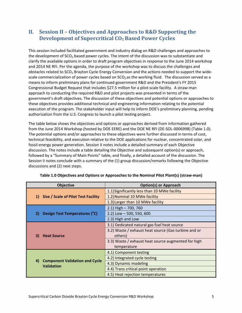
The table below shows the objectives and options or approaches derived from information gathered from the June 2014 Workshop (hosted by DOE EERE) and the DOE NE RFI (DE‐SOL‐0006998) (Table 1.0). The potential options and/or approaches to these objectives were further discussed in terms of cost, technical feasibility, and execution relative to the DOE applications for nuclear, concentrated solar, and fossil‐energy power generation. Session II notes include a detailed summary of each Objective discussion. The notes include a table detailing the Objective and subsequent option(s) or approach, followed by a “Summary of Main Points” table, and finally, a detailed account of the discussion. The Session II notes conclude with a summary of the (1) group discussion/remarks following the Objective discussions and (2) next steps.
Table 1.0 Objectives and Options or Approaches to the Nominal Pilot Plant(s) (straw‐man)
Objective Option(s) or Approach
1) Size / Scale of Pilot Test Facility
1.1) Significantly less than 10 MWe facility
1.2) Nominal 10 MWe facility
1.3) Larger than 10 MWe facility
2) Design Test Temperatures (oC)
2.1) High – 700, 760
2.2) Low – 500, 550, 600
2.3) High and Low
3) Heat Source
3.1) Dedicated natural gas fuel heat source
3.2) Waste / exhaust heat source (Gas turbine and or others)
3.3) Waste / exhaust heat source augmented for high temperature
4) Component Validation and Cycle Validation
4.1) Component testing
4.2) Integrated cycle testing
4.3) Dynamic modeling
4.4) Trans critical point operation
4.5) Heat rejection temperatures
Supercritical Carbon Dioxide Brayton Cycle Energy Conversion R&D Workshop 6
Before the group discussion of the objectives and options or approaches to the nominal power plant(s) ensued, Ross Brindle (the workshop facilitator) asked if there were any questions regarding scope or the purpose of the discussion, including: (1) distinguishing the roles of government and industry in the facility; (2) ongoing or future research that will occur outside of the demonstration facility effort; (3) if the focus is not the future (50 MW), what is the point of the 10 MW?; and (4) vision (i.e., short‐ to long‐term). The resulting discussion included the following considerations. An industry or manufacturer will not stop production (to shift to a new product) or sell a warranty to an unproven system, so there is a need for operational experience to prove the system and reliability. It was suggested to manufacture all of the piping at the desired temperature and make the components at known materials, then switch out the components that face challenges at higher temperatures as they are developed. Brindle asked, “Are there commonalities in this room and what can be built that provides the platform to go in different directions?” The group agreed that there is not a single solution, but it would be beneficial to build a facility that meets the needs of multiple stakeholders. Brindle asked about the group’s vision. The group again agreed that everyone’s vision is different and the facility should be designed to benefit as many of the common areas as possible. The group was asked if it makes sense to have more than one facility so that there could be an opportunity to focus on different goals. The group said that the expected budget would make constructing one facility challenging, let alone two (or more). It was suggested that the facility should be built as a test bed where multiple users could “plug and play” to test various components. The group has three needs for the cycle: (1) test a plant – long run times, proving viability of materials and operational strategies; (2) test a component(s) – build and test individual system components; and (3) better modeling. Sal Golub, U.S. Department of Energy, asked if he could address the audience regarding the fundamental issue of whether the aim should be a demonstration plant, pilot plant, or a component test facility, and whether electricity should be generated (to the grid). He suggested that the group consider what is trying to be achieved and then work backwards from that point. In a wide‐scale, commercial deployment, there will be different industries, temperatures, and scales that will employ SCO2 cycles. From a nuclear perspective, the technology should available so that when a designer is ready, the technology can be acquired and plugged into a facility. No matter what the group discusses, the following three criteria must be followed: (1) whatever system is selected, it has to make progress to from where the technology is today to where it needs to be in the future, (2) the government has to afford it, and (3) the facility has to demonstrate industry has a share in the project.
Brindle then asked for the group’s reaction to the discussion up to this point of the workshop. The group then engaged in open dialogue, which is highlighted by the following key points:
550°C seems to the “right” temperature based on initial feedback.
Industry needs to sell a certain number of units to pursue a technology for a given application. o Technology that is not proven will not be adopted by industry because of the risk. o Government backed loans for first of kind adopters for new technology would be
beneficial.
Nuclear applications for SCO2 power cycles will not require high numbers of units to be installed in the near future. Waste heat recovery (WHR) has thousands of applications available that industry is actively pursuing. A test system at these conditions does not make much sense because the market is already pushing development.
DOE work to validate models would be greatly beneficial.
Supercritical Carbon Dioxide Brayton Cycle Energy Conversion R&D Workshop 7
A key assumption is that component and material development by industry will continue in parallel with the DOE effort.
The vision is that the technology is available; think about the facility as a way to move toward that vision and utilize the resources that are available to drive toward that goal.
Perhaps it would make sense for DOE to buy into a 10 MW system that industry is building or considering building. This would allow utilization of the funds in a way that maximizes value, especially if someone in industry is considered building. (A facility will be needed either way, whether it is bought or built.)
There is value in a facility that can be turned on and off, but it would be difficult to make adjustments to an operational plant.
One organization’s representative said he would welcome a government cost share for a WHR project, but that is not recommended. It was said that if that happens, SCO2 will never go beyond WHR. The organization cannot afford the investment and risk for larger scale systems.
Once a facility is producing power and tied in to the grid, the ability to test is lost. There is a cost benefit to using facilities that already exist, maybe not instead of “the facility,” but in tandem to utilize lessons learned.
One organization has a vision of multi‐megawatt scales with components to be built and validated by vendors before being plugged into their loop.
Should the concept of having one stationary facility be favored over one that is potentially movable to other locations? The use of multiple and/or movable facilities was discussed at length. The multiple facilities concept is dependent on the nature and amount of DOE funding. DOE envisions the facility will go through competitive solicitation.
The “plug and play” concept makes sense for some components, like heat exchangers, but it may not make sense for others (i.e., opening up a turbomachine and dropping in other blades and bearings). This concept would enable the ability look at what components need, how they can be tested, and the overall system interaction.
Supercritical Carbon Dioxide Brayton Cycle Energy Conversion R&D Workshop 8
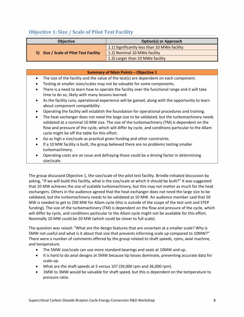
Objective1:Size/ScaleofPilotTestFacility
Objective Option(s) or Approach
5) Size / Scale of Pilot Test Facility
1.1) Significantly less than 10 MWe facility
1.2) Nominal 10 MWe facility
1.3) Larger than 10 MWe facility
Summary of Main Points – Objective 1
The size of the facility and the value of the test(s) are dependent on each component.
Testing at smaller sizes/scales may not be valuable for some components.
There is a need to learn how to operate the facility over the functional range and it will take time to do so, likely with many lessons learned.
As the facility runs, operational experience will be gained, along with the opportunity to learn about component compatibility.
Operating the facility will establish the foundation for operational procedures and training.
The heat exchanger does not need the large size to be validated, but the turbomachinery needs validated at a nominal 10 MW size. The size of the turbomachinery (TM) is dependent on the flow and pressure of the cycle, which will differ by cycle, and conditions particular to the Allam cycle might be off the table for this effort.
Go as high a size/scale as practical given funding and other constraints.
If a 10 MW facility is built, the group believed there are no problems testing smaller turbomachinery.
Operating costs are an issue and defraying those could be a driving factor in determining size/scale.
The group discussed Objective 1, the size/scale of the pilot test facility. Brindle initiated discussion by asking, “If we will build this facility, what is the size/scale at which it should be built?” It was suggested that 10 MW achieves the size of scalable turbomachinery, but this may not matter as much for the heat exchangers. Others in the audience agreed that the heat exchanger does not need the large size to be validated, but the turbomachinery needs to be validated at 10 MW. An audience member said that 50 MW is needed to get to 200 MW for Allam cycle (this is outside of the scope of the test unit and STEP funding). The size of the turbomachinery (TM) is dependent on the flow and pressure of the cycle, which will differ by cycle, and conditions particular to the Allam cycle might not be available for this effort. Nominally 10 MW could be 20 MW (which could be closer to full scale).
The question was raised: “What are the design features that are uncertain at a smaller scale? Why is 5MW not useful and what is it about that size that prevents informing scale up compared to 10MW?” There were a number of comments offered by the group related to shaft speeds, rpms, axial machine, and temperature.
The 5MW size/scale can use more standard bearings and seals at 10MW and up.
It is hard to do axial designs at 5MW because tip losses dominate, preventing accurate data for scale‐up.
What are the shaft speeds at 5 versus 10? (39,000 rpm and 36,000 rpm).
1MW to 3MW would be valuable for shaft speed, but this is dependent on the temperature to pressure ratio.
Supercritical Carbon Dioxide Brayton Cycle Energy Conversion R&D Workshop 9
There is interest from the audience members to scale to as high a size as practical; if 50 MW was built, it would be close to market, but 10 MW is practical. Although the purpose was not to drive to consensus, the majority of the audience made arguments/suggestions in favor of the “nominal 10 MWe facility” with a caveat to go as high as possible/practical. It was then suggested to that the group create a list of all technical issues and prioritize them in relation to the available resources. The purpose of the meeting was to fact find, not to prioritize, so there was no action taken. Brindle welcomed comments in favor of the “significantly less than 10 MWe facility” and “larger than 10 MWe facility,” but the conversation strayed back to the “nominal 10 MWe facility.” Two questions were asked, “Is the level of funding and the 10 MW size a viable option?” and “At what level does a critical risk need to be retired – what level should the cycle and components be commercially available?” These are management and risk assessment issues that will also require consideration. It was suggested to form a list of seals, bearings, and materials that need to be developed, tested, and/or validated for the cycle. 10 MW to 20 MW is a 1 inch difference in blade diameter and axial is most likely the best choice because stages can be added to reduce shaft speed, oil bearings can be used, and commercial gearboxes can be purchased. If a 10 MW facility is built, the group did not anticipate problems testing smaller turbomachinery. Operating costs are an issue and the need to minimize those costs could be a driving factor in determining size/scale. It was asked, “What do we get out of this demonstration plant if we are not going to characterize components to their limits?” The size of the facility and the value of the test(s) are dependent on each component. Testing at some sizes/scales may not be valuable for some components. An audience member said that it will prove invaluable to learn how to operate the facility over the functional range and it will take time to do so, likely with many lessons learned. As the facility runs, operational experience will be gained, along with the opportunity to learn about component compatibility. This will help when the time comes to shift to a utility and warranty the plant. Operating the facility will establish the foundation for operational procedures and training.
Supercritical Carbon Dioxide Brayton Cycle Energy Conversion R&D Workshop 10
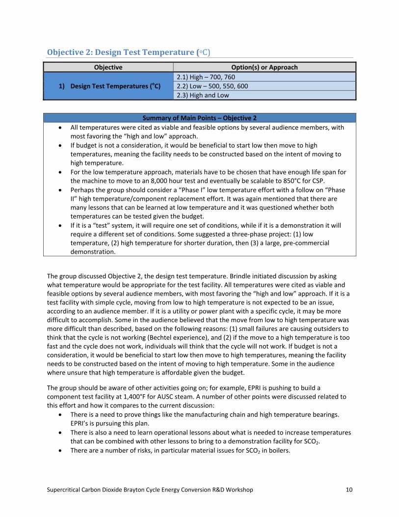
Objective2:DesignTestTemperature(oC)
Objective Option(s) or Approach
1) Design Test Temperatures (oC)
2.1) High – 700, 760
2.2) Low – 500, 550, 600
2.3) High and Low
Summary of Main Points – Objective 2
All temperatures were cited as viable and feasible options by several audience members, with most favoring the “high and low” approach.
If budget is not a consideration, it would be beneficial to start low then move to high temperatures, meaning the facility needs to be constructed based on the intent of moving to high temperature.
For the low temperature approach, materials have to be chosen that have enough life span for the machine to move to an 8,000 hour test and eventually be scalable to 850°C for CSP.
Perhaps the group should consider a “Phase I” low temperature effort with a follow on “Phase II” high temperature/component replacement effort. It was again mentioned that there are many lessons that can be learned at low temperature and it was questioned whether both temperatures can be tested given the budget.
If it is a “test” system, it will require one set of conditions, while if it is a demonstration it will require a different set of conditions. Some suggested a three‐phase project: (1) low temperature, (2) high temperature for shorter duration, then (3) a large, pre‐commercial demonstration.
The group discussed Objective 2, the design test temperature. Brindle initiated discussion by asking what temperature would be appropriate for the test facility. All temperatures were cited as viable and feasible options by several audience members, with most favoring the “high and low” approach. If it is a test facility with simple cycle, moving from low to high temperature is not expected to be an issue, according to an audience member. If it is a utility or power plant with a specific cycle, it may be more difficult to accomplish. Some in the audience believed that the move from low to high temperature was more difficult than described, based on the following reasons: (1) small failures are causing outsiders to think that the cycle is not working (Bechtel experience), and (2) if the move to a high temperature is too fast and the cycle does not work, individuals will think that the cycle will not work. If budget is not a consideration, it would be beneficial to start low then move to high temperatures, meaning the facility needs to be constructed based on the intent of moving to high temperature. Some in the audience where unsure that high temperature is affordable given the budget.
The group should be aware of other activities going on; for example, EPRI is pushing to build a component test facility at 1,400°F for AUSC steam. A number of other points were discussed related to this effort and how it compares to the current discussion:
There is a need to prove things like the manufacturing chain and high temperature bearings. EPRI’s is pursuing this plan.
There is also a need to learn operational lessons about what is needed to increase temperatures that can be combined with other lessons to bring to a demonstration facility for SCO2.
There are a number of risks, in particular material issues for SCO2 in boilers.
Supercritical Carbon Dioxide Brayton Cycle Energy Conversion R&D Workshop 11
Utilities will not take on risk without a proven test and system. Highest steam temperatures are currently at 620°C (the temperature utilities are most comfortable with).
The AUSC consortium has been working for 10 years to develop materials and systems.
There is a speculative $50 million price tag for the steam Rankine test loop.
For the low temperature approach, materials have to be chosen that have enough life span for the machine to move to an 8,000 hour test and eventually be scalable to 850°C for CSP. Pressures are lower than for supercritical water and temperature cannot be considered independent of pressure. It was said that low temperature versus high temperature is more of a program planning issue. Perhaps the group should consider a “Phase I” low temperature effort with a follow on “Phase II” high temperature/component replacement effort. It was again mentioned that there are many lessons that can be learned at low temperature and it was questioned whether both temperatures can be tested given the budget. There seemed to be agreement in the room that 2.3 (high and low temperature) was a good approach, with the caveat of moving from low temperature to high temperature. The budget was then discussed at length. It was noted that budget is a strong driver for the option selection and whatever selections are made under the other Objectives influence what can be completed. An example was given of how $10 million worth of piping for higher temperature capability versus $5 million worth of piping for lower temperatures is a difference that could be used to offset fuel costs and affect decision making.
The buildup approach was considered a feasible option because there are commercial offerings at low temperatures. It was asked whether the group should prove the technology at a low temperature or aim for high temperature (riskier). This effort is not the last step between now and commercialization, so the group needs to consider that there are many valuable lessons learned through the validation and operation of low temperature. It may be unrealistic to suggest moving at the pace the group has discussed up to this point in the workshop. There was then discussion about the heat source for the loop and how to obtain the temperatures necessary with the needed high flow rates.
Carelton University is inductively heating sections of piping (250 kw) to increase SCO2 temperatures to process conditions (relatively small flows).
Obtaining a 30 MWth heater at 700°C is expensive and potentially cost prohibitive.
If a heater was purchased instead of using a heat exchanger, it was questioned if the cycle is being adequately tested.
“Why not have the heater heat a separate loop that then heats the primary heat exchanger?” There are difficulties with managing heat exchange at those temperatures and heated flue gas is easier.
The cost of a high temperature loop is $40 million to $200 million based on an informal poll of group members. In order to stay at low temperatures: (1) build and operate what is possible, (2) focus on what can be accomplished in the near‐term because of cost limitations, and (3) prove this system and then let the market drive down costs once three or more plants have been built. It would be useful to have a matrix of combinations of temperatures and sizes where certain things can be evaluated. There is a need to get to high temperatures. The design of a high temperature facility may make some sense before low, but why not begin at low to accomplish the goals within that scope? It was said that an induction heater or duct burner and high temperature piping (not tearing out lower temperature) could be added. If it is a “test” system, it will require one set of conditions, while if it is a demonstration it will require a different set of conditions. Some suggested a three‐phase project: (1) low temperature, (2) high temperature for shorter duration, then (3) a large, pre‐commercial demonstration.
Supercritical Carbon Dioxide Brayton Cycle Energy Conversion R&D Workshop 12
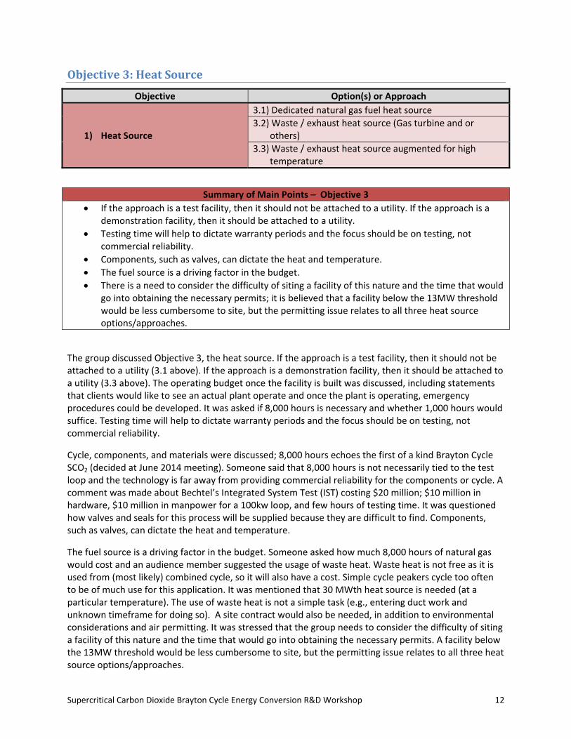
Objective3:HeatSource
Objective Option(s) or Approach
1) Heat Source
3.1) Dedicated natural gas fuel heat source
3.2) Waste / exhaust heat source (Gas turbine and or others)
3.3) Waste / exhaust heat source augmented for high temperature
The group discussed Objective 3, the heat source. If the approach is a test facility, then it should not be attached to a utility (3.1 above). If the approach is a demonstration facility, then it should be attached to a utility (3.3 above). The operating budget once the facility is built was discussed, including statements that clients would like to see an actual plant operate and once the plant is operating, emergency procedures could be developed. It was asked if 8,000 hours is necessary and whether 1,000 hours would suffice. Testing time will help to dictate warranty periods and the focus should be on testing, not commercial reliability.
Cycle, components, and materials were discussed; 8,000 hours echoes the first of a kind Brayton Cycle SCO2 (decided at June 2014 meeting). Someone said that 8,000 hours is not necessarily tied to the test loop and the technology is far away from providing commercial reliability for the components or cycle. A comment was made about Bechtel’s Integrated System Test (IST) costing $20 million; $10 million in hardware, $10 million in manpower for a 100kw loop, and few hours of testing time. It was questioned how valves and seals for this process will be supplied because they are difficult to find. Components, such as valves, can dictate the heat and temperature.
The fuel source is a driving factor in the budget. Someone asked how much 8,000 hours of natural gas would cost and an audience member suggested the usage of waste heat. Waste heat is not free as it is used from (most likely) combined cycle, so it will also have a cost. Simple cycle peakers cycle too often to be of much use for this application. It was mentioned that 30 MWth heat source is needed (at a particular temperature). The use of waste heat is not a simple task (e.g., entering duct work and unknown timeframe for doing so). A site contract would also be needed, in addition to environmental considerations and air permitting. It was stressed that the group needs to consider the difficulty of siting a facility of this nature and the time that would go into obtaining the necessary permits. A facility below the 13MW threshold would be less cumbersome to site, but the permitting issue relates to all three heat source options/approaches.
Summary of Main Points – Objective 3
If the approach is a test facility, then it should not be attached to a utility. If the approach is a demonstration facility, then it should be attached to a utility.
Testing time will help to dictate warranty periods and the focus should be on testing, not commercial reliability.
Components, such as valves, can dictate the heat and temperature.
The fuel source is a driving factor in the budget.
There is a need to consider the difficulty of siting a facility of this nature and the time that would go into obtaining the necessary permits; it is believed that a facility below the 13MW threshold would be less cumbersome to site, but the permitting issue relates to all three heat source options/approaches.

Supercritical Carbon Dioxide Brayton Cycle Energy Conversion R&D Workshop 13
Objective4:ComponentValidationandCycleValidation
Objective Option(s) or Approach
1) Component Validation and Cycle Validation
4.1) Component testing
4.2) Integrated cycle testing
4.3) Dynamic modeling
4.4) Trans critical point operation
4.5) Heat rejection temperatures
Summary of Main Points – Objective 4
A demonstration facility would be plugged into the grid, turned on, and (hopefully) work as expected, while a test facility allows individuals to “plug and play” with different components.
Even through the use of a simple cycle a lot will be learned about the five options (component testing, integrated cycle testing, dynamic modeling, trans critical point operation, and heat rejection temperatures). There is a need to examine all of the options/approaches above because they are all equally important.
The group felt that option 4.2 (integrated cycle testing) is an “absolute must” because it includes the rest of the options.
Once the cycle is proven, the infrastructure can be used to do component testing.
A meaningful test time depends on what is being testing (e.g., hot restart, cold restart, emergency, ramp up, ramp down) and the related timescales.
If the plan is to put power on the grid, there is certain criterion from a utility that must be followed.
Any test has to be able to demonstrate efficiency.
With regard to putting electricity on grid: it depends on location of the test facility and test duration, it is important to demonstrate, and it needs to be decided whether this is a test or demonstration facility.
The group discussed Objective 4, component validation versus cycle validation. The group initiated discussion by questioning whether the aim is a test/research facility (80/20 cost share) or a demonstration facility (50/50 cost share). A demonstration facility would be plugged into the grid, turned on, and (hopefully) work as expected, while a test facility allows individuals to “plug and play” with different components. Even through the use of a simple cycle a lot will be learned about the five options (component testing, integrated cycle testing, dynamic modeling, trans critical point operation, and heat rejection temperatures). There is a need to examine all of the options/approaches above because they are all equally important. The heat exchangers are an important issue in terms of how the exhaust heat is effectively recovered. An anecdote from the Navy perspective was shared. The Navy has invested $500 million over 40+ years in waste heat recovery and it has not worked up to this point with a variety of fluids, because of the heat exchanger problem. Building a robust and reliable heat exchanger is the highest risk.
The group felt that option 4.2 (integrated cycle testing) is an “absolute must” because it encompasses all of the other options. It was suggested that 4.2 (integrated cycle testing) cannot be completed if 4.1 (component testing) is not, with the goal of progressing to option 4.2 (integrated cycle testing). Once the cycle is proven, the infrastructure can be used to do component testing. If 50% efficiency could be
Supercritical Carbon Dioxide Brayton Cycle Energy Conversion R&D Workshop 14
demonstrated with this system at 10 MW, it would be considered a tremendous achievement. This would show the ability to run an integrated cycle for “X” hours at a time.
Brindle asked “What is meaningful test time?” The group said that it depends on what is being testing (e.g., hot restart, cold restart, emergency, ramp up, ramp down) and the related timescales. If the plan is to put power on the grid, there is certain criterion from a utility that must be followed. Someone said that they are not looking for 8,000 hours durability data, rather start up, shut down, moving through transients (each of these tests is a few hours [less than 20 hours]). The 8,000 hours was mentioned because it was a separate timescale to establish capacity factor for the hardware. There should be a test plan and objectives for an integrated cycle test to meet those goals. Several comments were offered by the group:
It is difficult to get long test times on the whole loop and easier on single components.
Options 4.4 (trans critical point operation) and 4.5 (heat rejection temperatures) can affect the design of the precooler.
Option 4.4 (trans critical point operation) is easily done at bench scale, because there are not high temperatures and pressures.
Any test has to be able to demonstrate efficiency. There is no efficiency target for the 10 MW loop, but there are individual component efficiencies. These should match the modeling results. With regard to putting electricity on grid: (1) it depends on location of the test facility and test duration, (2) it is important to demonstrate, and (3) it needs to be decided whether this is a test or demonstration facility. It was suggested that the facility conducts component testing for the first year or two and then moves to a demonstration phase. If that is the ultimate vision, site selection and all decisions would need to be driven by that idea. An audience member said that 1,000 testing hours can be completed in a laboratory, while 8,000 hours cannot, so the ability to show degradation mechanisms will be lost (if testing for only 1,000 hours). There is not enough data on materials to do an 8,000 hours test. A 1,000‐hour laboratory test provides material life modeling data to predict behavior that would then be validated in a longer test.
It is probably not possible to remove TM from a test facility that is not grid connected and then connect and test it somewhere else, because no one has the necessary flow rates to prove it. It is important to select the “correct” site from the beginning, which would make this issue a moot point. Another individual was confident that the test facility could be constructed one place, then moved to another location and plugged in. An NE development facility that worked on component development was provided as a reference of what could be done.
Supercritical Carbon Dioxide Brayton Cycle Energy Conversion R&D Workshop 15
ConcludingGroupDiscussion/Remarks
Overall, there was a fairly clear view of the majority opinion for each of the objectives, but arguments were presented for and against each of the provided Objectives’ options/approaches. It was asked if there were any other aspects of the envisioned facility that have yet to be discussed. There was a discussion of materials, including the following highlights:
There is an opportunity to build inter‐laboratory and industrial collaboration around materials and heat exchangers.
Four different groups are conducting corrosion testing.
The opportunity exists for collaboration amongst the organizations in the room. The group needs to communicate so that overlapping tests of the same materials are not completed at the same temperatures. With mutual collaboration, a range of cycles can be covered instead of working independently toward the same goal.
EPRI is willing to host the first steps of this collaboration.
Many participants would be interested in a facility that can transition from test to demonstration facility. It was said that 1,000 hours can be done in the laboratory and industry wants/needs 8,000 hours to test materials and confidence. Another consideration for the STEP facility is how it will work in the context of the other facilities and infrastructure that are built or are being built. The timeframe for this program is an operational STEP facility by 2019, preceded by the FOA in 2015.
It was asked if it will be a DOE‐owned facility with industry supplying components. It will be a public‐private partnership, but the details are to be determined. Intellectual property sensitivities were also noted, with a framework also to be determined. The components and systems are also to be determined, because the effort could be structured in multiple different ways with multiple different funding/contract mechanisms. The FOA will have to define these “TBD” issues, including who owns the facility design.
NextSteps
DOE is at the point where they will be having meetings with OMB to discuss FY15 and FY16 budgets.
When the program is authorized, maybe in December 2014 or January 2015, the next phase will begin. It is unknown whether this could be another focused RFI, a draft RFP, or the FOA. More collaboration will occur between the workshop participants and DOE.
The issue of whether electricity should be put on the grid is a simple cost benefits analysis and should be undertaken.
There is a desire within DOE to create a stakeholder working group comprised of government, vendors, buyers, industry, utilities, suppliers, etc., complete with names, contact info, etc., so that all interested groups can voice their positions and all interests can be served. Any ideas on how to go about this process were welcomed, and public forums will still occur.
Supercritical Carbon Dioxide Brayton Cycle Energy Conversion R&D Workshop 16
AppendixA:WorkshopAgenda
Recommended