Specifications for Approval ofType of Electricity Meters,Instrument Transformers andAuxiliary Devices
Whereas subsection 12(1) of the Electricity and Gas Inspection Regulations provides that thedirector appointed under subsection 26(1) of the Electricity and Gas Inspection Act shall establishspecifications relating to design, composition, construction and performance to which any meter or anyclass, type or design of meter shall conform before permission or approval with regard to that meter or suchclass, type or design of meter may be given pursuant to section 9 of the said Act.
Therefore, the Director of the Legal Metrology Branch of the Department of Industry is pleasedhereby to establish the annexed specifications for the approval of the types of electricity meters, instrumenttransformers and auxiliary devices referred to therein.
SPECIFICATIONS FOR APPROVAL OF TYPE
OF
ELECTRICITY METERS
INSTRUMENT TRANSFORMERS
AND
AUXILIARY DEVICES

CONTENTS
SECTION PAGE
1. SCOPE . . . . . . . . . . . . . . . . . . . . . . . . . . . . . . . . . . . . . . . . . . . . . . . . . . . . . . . . . . . . . . . 1
2. DEFINITIONS . . . . . . . . . . . . . . . . . . . . . . . . . . . . . . . . . . . . . . . . . . . . . . . . . . . . . . . . . 2
3. GENERAL . . . . . . . . . . . . . . . . . . . . . . . . . . . . . . . . . . . . . . . . . . . . . . . . . . . . . . . . . . . 11
4. INDUCTION TYPE WATT HOUR METERS . . . . . . . . . . . . . . . . . . . . . . . . . . . . . . . . 23
5. INDUCTION TYPE VAR HOUR AND Q-HOUR METERS . . . . . . . . . . . . . . . . . . . . 38
6. STATIC INTEGRATING METERS . . . . . . . . . . . . . . . . . . . . . . . . . . . . . . . . . . . . . . . . 47
7. DEMAND METERS . . . . . . . . . . . . . . . . . . . . . . . . . . . . . . . . . . . . . . . . . . . . . . . . . . . . 54
8. INDUCTION TYPE LOSS METERS . . . . . . . . . . . . . . . . . . . . . . . . . . . . . . . . . . . . . . 65
9. STATIC LOSS METERS . . . . . . . . . . . . . . . . . . . . . . . . . . . . . . . . . . . . . . . . . . . . . . . . 70
10. TRANSDUCERS . . . . . . . . . . . . . . . . . . . . . . . . . . . . . . . . . . . . . . . . . . . . . . . . . . . . . . 74
11. NULL BALANCING INSTRUMENTS . . . . . . . . . . . . . . . . . . . . . . . . . . . . . . . . . . . . . 81
12. PULSE DEVICES . . . . . . . . . . . . . . . . . . . . . . . . . . . . . . . . . . . . . . . . . . . . . . . . . . . . . . 92
13. PROGRAMMABLE DEVICES AND PULSE RECORDERS . . . . . . . . . . . . . . . . . . . . 96
14. INSTRUMENT TRANSFORMERS . . . . . . . . . . . . . . . . . . . . . . . . . . . . . . . . . . . . . . . . 100
15. STATIC DEMAND METERS . . . . . . . . . . . . . . . . . . . . . . . . . . . . . . . . . . . . . . . . . . . . 115
16. INDUCTION TYPE VOLTAGE-SQUARE HOUR METERS . . . . . . . . . . . . . . . . . . . . 120
17. STATIC VOLTAGE-SQUARE HOUR METERS . . . . . . . . . . . . . . . . . . . . . . . . . . . . . 124
18. SUB-METERING . . . . . . . . . . . . . . . . . . . . . . . . . . . . . . . . . . . . . . . . . . . . . . . . . . . . . . 128
19. SIGNAL CONVERTERS . . . . . . . . . . . . . . . . . . . . . . . . . . . . . . . . . . . . . . . . . . . . . . . . 131

- 1 -
SECTION 1 - SCOPE
This specification establishes acceptable performancecriteria for new types of electricity meters, instrumenttransformers and auxiliary devices intended for use in revenuemetering. The criteria apply also to modifications which may bemade, in future, to existing approved devices.
This document refers to the following and where suchreference is made it shall be considered to refer to the latestedition and may revisions thereto:
Canadian Standards Association Standard C17; Electricity Meters.
Canadian Standards Association Standard C13; InstrumentTransformers.
National Standard of Canada CAN-Z234.1; Canadian Metric PracticeGuide.
American National Standards Institute Standard C37-90a/Instituteof Electrical and Electronic Engineers Standard 472; IEEE Guidefor Surge Withstand Capability (SWC) Tests.
United States Department of Defence Military Standard MIL-STD-461B; Electromagnetic Emission and Susceptibility Requirementsfor the Control of Electromagnetic Interference.
National Standard of Canada CAN3-Z234.4; All-Numeric Dates andTimes.
- 2 -
SECTION 2 - DEFINITION
Definitions relating to meters and auxiliary devices areincluded in this section. Definitions pertaining to instrumenttransformers are listed in subsection 14-2.
2-1 Accuracy Rating of a Null Balancing Instrument. The limitwhich errors will not exceed when the instrument is used underany combination of rated operating conditions, expressed as apercent of the span.
2-2 Ambient Temperature. The temperature of the medium, suchas gas or liquid, in which the device or apparatus underexamination is immersed.
2-3 Approval Test. The testing of one or more meters or otheritems under various controlled conditions to ascertain theperformance characteristics of the type of which they arerepresentative.
2-4 Auxiliary Timing Device. A timing device which controlscertain functions of other meters of devices but which isseparately housed.
2-5 Basic Current. The value of current in accordance withwhich the relevant performance of the meter is fixed. For aninduction-type watt hour meter this is equal to the high loadtest current.
2-6 Bloc Interval Demand Meter. See Integrating Demand Meter.
2-7 Case (of the Meter). The complete outside enclosure.
2-8 Chart. Graduated material upon which a pen or stylus drawsa record, or upon which is printed a record, of the quantity orquantities being measured by an instrument.
2-9 Common Mode Interference. A form of interference whichappears between any measuring circuit terminal and ground.
Continuous Cumulative Demand Register. A register thatdisplays the continuous sum of all the peak demands of eachdemand interval subsequent to the register being reset.
2-10 Cover (of the Meter). That part of the case which isremovable, for access to working parts and adjustments.
- 3 -
2-11 Creep. A meter is said to creep if the rotormakes a complete revolution when the voltage coils are energizedwith rated voltage and with no current in any current coil.
2-12 Cumulative Demand Register. A register thatindicates the sum of the previous maximum demand readings priorto reset. When reset, the present reading is added to theprevious accumulated readings. The maximum demand for thepresent reading period is the difference between the present andprevious readings.
2-13 Current Range. The range of currents over whichthe meter purports to meet the requirements of thesespecifications. The upper and lower limits are maximum ratedcurrent.
2-14 Damping Characteristic (of a null balancinginstrument) The maximum overshoot (if any) beyond the point offinal rest, expressed in percent of span.
2-15 Dead Band (of a null balancing instrument). Therange through which the measured quantity can be varied withoutinitiating response, expressed in percent of span.
2-16 Demand. The rate at which the particularquantity, i.e. active energy, reactive energy, etc., is beingsupplied to the load. Generally, it is indicated, recorded orcomputed as the average obtained over a specified time interval.
2-17 Demand Interval (of an integrating demand meter orof a pulse recorder). The specified interval of time on whicha demand measurement is based.
2-18 Demand Interval Deviation. The difference betweenthe measured demand interval and the specified demand interval,expressed as a percentage of the specified demand interval.
2-19 Demand Meter. A meter that indicates or recordseither the demand, maximum demand, or both.
Note: A demand meter may be either an integrating or laggeddemand meter.
- 4 -
2-20 Dielectric Tests. Tests consisting of theapplication of a voltage higher than the rated voltage for aspecified time for the purpose of determining the adequacyagainst breakdown of insulating materials and spacing undernormal conditions.
2-21 Director. The Director of the Legal MetrologyBranch, Department of Industry.
2-22 Disc Constant Kh. The registration, expressed inunits of the quantity being measured per revolution of the disc.
2-23 Display. A means for visually identifying andpresenting electronically measured or calculated quantities andother information.
2-24 Electromagnetic Interference (EMI). Anyelectromagnetic energy which interrupts, obstructs or otherwisedegrades or limits the effective performance of metering.
2.25 Error.
(a) Absolute Error. The value registered by the meter minusthe true value.
(b) Relative Error. The ratio of the absolute error to thetrue value.
(c) Percentage Error. The relative error multiplied by 100.The percentage error is given by the following:
Percentage Error = Meter Registration - True Value X 100
True Value
(d) Error of a Transducer. The observed value of the outputminus the ideal value, where the ideal value is calculated fromthe value of the measured input quantity and the transferconstant Ka.
2-26 External Circuit Resistance. The resistance ofthat part of the measuring circuit which is external to theinstrument.
2-27 Frame (of a Meter) That part to which are affixedthe working parts and adjustments.
- 5 -
2-28 Full Scale Value. The largest value of theactuating electrical quantity that can be indicated on the scaleor, in the case of an instrument having its zero between the endof the scale, the full-scale value is the arithmetic sum of thevalues of the actuating electrical quantity corresponding to thetwo ends of the scale.
2-29 Indicating Demand Meter. A demand meter equippedwith a readout that indicates demand, maximum demand or both.
2-30 Integral Timing Device. One which is mountedwithin the case of the billing instrument.
2-31 Integrating Demand Meter (Block-Interval DemandMeter). A demand meter in which the demand is derived throughintegration of the measured quantity. With respect to time.
2-32 Interference. Any spurious voltage or currentappearing in the circuits of the instrument which interfereswith proper operation of the instrument.
2-33 Lagged Demand Meter. A demand meter in which theindication of the demand is subject to a characteristic time lagproduced by either thermal or mechanical means.
2-34 Minimum Current. The smallest load current forwhich a device must operate within specified error limits.Unless otherwise specified, the minimum current shall be takento be 1% of Imax.
2-35 Maximum Demand. The greatest of all demands whichhave occurred during a specific period of time, usually thebilling period i.e. a month, two months, etc.
2-36 Maximum Demand Indicator (Demand Attachment). Amechanism intended for mounting in an electricity meter, whichindicates or registers maximum demand.
Note: The mechanism may also register energy.
2-37 Meter Multiplier. The factor by which theregister reading must be multiplied to obtain the registrationin the stated units.
- 6 -
2-38 Multi-Rate Meter. A meter provided with aregister having more than one readout, each readout becomingoperative at times corresponding to different rates of charge.
2-39 Nominal Power Factor (or Reactive Factor) (of atransducer). The ratio of rated input power to the product ofthe rated voltage and maximum rated input current for singlephase transducers. For polyphase transducers the product ismultiplied by either /3 (when the nominal voltage is phase-phase) or by 3 (when the nominal voltage is phase-neutral).
Note: (1) power may be active or reactive according tothe kind of transducer.
(2) Where no maximum rating is stated the value ofrated current is substituted.
2-40 Nominal Value (of a transducer). A value, or oneof the values indicating the rating and intended use of atransducer.
2-41 Normal Mode Interference. A form of interferencewhich appears between measuring circuit terminals.
2-42 Percentage Registration. The ratio of the actualregistration of the meter to the true value of the quantitybeing measured, expressed as a percentage.
2-43 Power Factor. The ratio of the active power tothe apparent power. Power factor is given by cos 2 , where 2is the phase angle of the load.
2-44 Prescalar Unit. The ratio of the number of inputpulses per output pulse.
2-45 Pulse Count Deviation (of a pulse recorded). Thedifference between the number of recorded pulses and the numberof pulses supplied to the input terminals of a pulse recorded(true count), expressed as a percentage of the true count.Pulse-count deviation is applicable to each data channel of apulse recorder.
2-46 Pulse Initiator. Any device used with a meter toinitiate pulses, the number of which is proportional to thequantity being measured.
- 7 -
2-47 Pulse Initiator Output Constant (Kp). The valueof the measured quantity for each outgoing pulse of a pulseinitiator expressed in kilowatt hours per pulse, kilovar hoursper pulse or other suitable units.
2-48 Q-Hour Meter. An electricity meter that measuresa quantity that may be obtained by effectively lagging theapplied voltage to a watthour meter by 60°. This quantity isone of the quantities used in calculating quadergy (var hours).
2-49 Range, of an indicating or recording meter. Theregion covered by the span and expressed by stating the two end-scale values.
Note: If the span passes through zero, the range isstated by inserting “zero” or “0" between the end-scale values.
2-50 Rated Frequency. The frequency or frequencies forwhich the meter is designed.
2-51 Rated Input Power (of a transducer). The nominalvalue of the measured quantity. Rated input power may beactive, reactive or apparent.
2-52 Rated Output (of a transducer). The nominal valueof the output quantity corresponding to the rated input power.The rated output is the span except for transducers having asymmetrical reversible input and output. In this case, therated output shall be half the span.
2-53 Rated Output Load Resistance (of a current-outputtype of transducer). The maximum value intended for connectionacross the output terminals.
2-54 Rated Voltage. The voltage or voltages for whichthe meter of device is designed.
2-55 Reactive Factor. The ratio of the reactive powerto the apparent power. Reactive factor is given by sin 2, where2 is the phase angle of the load.
2-56 Recording Demand Meter. A demand meter in whichthe indications of demand are recorded on a moving chart, paperor magnetic tape, or in solid state memory.
- 8 -
2-57 Reference Low-Load Speed. The rotor speed of aninduction watt hour meter operating under reference conditions(clause 4-5.1) and at 2.5% of maximum rated current, unity powerfactor.
2-58 Reference Temperature. The ambient temperature atwhich type testing is carried out and to which type tests atother temperatures may be referred.
2-59 Register. A device which registers the value ofthe quantity measured by the meter.
2-60 Register Ratio Rr (of an induction typeintegrating meter). The number of revolutions of the first gearof the register for one revolution of the first dial pointer.
2-61 Reset Time (of a demand register). The intervalof time within each demand interval during which the couplingbetween driving element and demand indicator is disconnected toallow the driving element to be restored to its initialposition.
2-62 Resetting Device. Device which enables themaximum demand to be reset manually or by other means.
2-63 Response Period (of a lagged demand meter). Thetime required for the meter indication to reach 90 percent ofthe final response to a step change in the measured quantity.
2-64 Sealing Device. Means whereby unauthorized accessto the interior and adjustments of a meter may be effectivelyimpeded.
2-65 Self-Contained Meter. A meter designed to beconnected directly to a power circuit, without the use ofexternal devices such as instrument transformers or shunts.
2-66 Single-Phase Test Constant K tc (of a polyphase varhour meter). The ratio of the single-phase watt hour discconstant Kwh of a class 90° meter to the var hour disc constant.
- 9 -
2-67 Single-Phase Watt Hour Disc Constant Kwh (of apolyphase var hour meter). The watt hour disc constant when aclass 90° meter is operated single phase with all voltagecircuits connected in parallel and all current circuitsconnected in series assisting.
2-68 Span. The algebraic difference between the end-scale values. For a transducer, the output span is thealgebraic difference between the upper and lower values of theoutput range.
2-69 Strip Chart (roll type chart). A chart in theform of a roll or reel upon which the measured quantities arerecorded.
2-70 Surge Withstand Capability (SWC). The capabilityof a device to withstand surges as demonstrated by a specifieddesign test.
2-71 Test Constant Ks (of a static watthour meter).The registration expressed in units of the quantity beingmeasured per indication of the test device.
2-72 Test Device (of a static watthour meter). Adevice provided on static meters to facilitate high-speed manualand automatic testing.
2-73 Test Link. A device provided to isolate thevoltage circuit from the current circuit, for the purpose oftesting.
2-74 Timing Device. A clock, timing motor, or device,used to determine the demand interval, drive a chart, or actuateany mechanism of the billing instrument on a time basis.
2-75 Transducer. A device for converting analternating electrical quantity into another quantity formeasurement purposes.
2-76 Transfer Constant K a (of a transducer). The ratioof the rated input to the rated output.
2-77 Transformer-Rated Meter. A meter designed for usewith specific instrument transformer ratios. It thus indicatesor records the primary quantity being measured.
- 10 -
2-78 Transformer-Type Meter. A meter designed to beused with instrument transformers.
2-79 Transient Overshoot. An excursion beyond thefinal steady-state value of output as the result of an inputchange.
2-80 True Value. The value established by a regulatoryauthority as being correct within certain limits of uncertainty.
2-81 Type. The designation assigned to a meter ordevice by the manufacturer for the purpose of distinguishing itsparticular design and construction from other designs, models orpatterns. Such type designation shall embrace only those rangesand ratings that are essentially similar in appearance andperformance.
2-82 Update Interval. The interval of time separatingthe periodic calculations of demand. The demand intervalnormally comprises several update intervals.
2-83 Volatile (Memory). Pertaining to a storage devicein which data cannot be retained without continuous powerdissipation.
2-84 Var Hour Meter (Reactive Energy Meter). Anintegrating instrument which measures reactive energy in varhours or in suitable multiples thereof.
2-85 Watt Hour Meter. An integrating instrument whichmeasures active energy in watt hours or in suitable multiplesthereof.
- 11 -
SECTION 3 - GENERAL
TABLE OF CONTENTS
SECTION PAGE
3-1 SCOPE . . . . . . . . . . . . . . . . . . . . . . . . 12
3-2 MECHANICAL REQUIREMENTS . . . . . . . . . . . . . . . 123-2.1 Design and Construction . . . . . . . . . . 123-2.2 Case . . . . . . . . . . . . . . . . . . . . 123-2.3 Inspection of Working Parts . . . . . . . . 123-2.4 Finish . . . . . . . . . . . . . . . . . . . 123-2.5 Terminals . . . . . . . . . . . . . . . . . 133-2.6 Sealing . . . . . . . . . . . . . . . . . . 143-2.7 Registers . . . . . . . . . . . . . . . . . 143-2.8 Displays . . . . . . . . . . . . . . . . . . 16
3-3 ELECTRICAL REQUIREMENTS . . . . . . . . . . . . . . . 163-3.1 Adjustability . . . . . . . . . . . . . . . 163-3.2 Voltage Ratings . . . . . . . . . . . . . . 173-3.3 Temperature Rise . . . . . . . . . . . . . . 173-3.4 Dielectric Tests . . . . . . . . . . . . . . 173-3.5 Carry-Over Time Base . . . . . . . . . . . . 193-3.6 Communications Security . . . . . . . . . . 193-3.7 Battery Conditions Indicator . . . . . . . . 19
3-4 MARKINGS . . . . . . . . . . . . . . . . . . . . . . . 193-4.1 Nameplates . . . . . . . . . . . . . . . . . 193-4.2 Nameplate Location . . . . . . . . . . . . . 19
3-5 PERFORMANCE REQUIREMENTS . . . . . . . . . . . . . . . 203-5.1 Reference Conditions for Tests . . . . . . . 203-5.2 EMI Susceptibility . . . . . . . . . . . . . 203-5.3 Effects of Ambient Temperature . . . . . . . 223-5.4 Reverse Operation . . . . . . . . . . . . . 22
- 12 -
SECTION 3 - GENERAL
3-1 SCOPE
These requirements apply to all appropriate types ofmeter or device which may be submitted for approval of type.
3-2 MECHANICAL REQUIREMENTS
3-2.1 Design & Construction. The design shall be suitablefor the intended purpose and expected service conditions.
The construction shall be mechanically and electricallysound, and the materials, finish, etc., shall be such as toprovide assurance of long life and sustained accuracy.
The meter or device shall be sufficiently shock-proofto withstand the handling encountered under normal conditions oftransportation by common carrier.
3-2.2 Case. The meter or device shall have a substantiallydust-proof case, not liable to distortion or damage due tonormal changes of temperature, presence of moisture, or othernormal conditions.
3-2.3 Inspection of Working Parts. Where applicable,provision shall be made for a clear view, with cover in place,of the register, the test dial and of those other working parts,the observation of which is necessary for efficient testing andreading of the meter.
3-2.4 Finish. The finish on the register face and nameplateshall be of durable material which will not fade, chip, flake,or discolour.
- 13 -
3-2.5 Terminals.
3-2.5.1 Markings. In order to facilitate the properconnections, the terminals on the meter shall have clearlyidentifiable markings, as follows:
(a) For a self-contained single-phase meter without accessories,sufficient identification will be the word “line” on theterminal cover of bottom-connected meters or on the base of asocket-type meter.
(b) For all other, a complete diagram of internal connections,satisfactorily located and secured, is required. If it issignificant for proper operations, the phase sequence shall beshown.
3-2.5.2 Sealing of Terminals. Except in the case of S-basemeters and back-connected switchboard meters, provision shall bemade so that the terminals may be effectively sealed againsttampering.
3-2.5.3 Dimensions.
3-2.5.3.1. The current terminals shall be large enough toaccommodate the proper cable size as given in Table 1.
TABLE I
MINIMUM SIZE CURRENT TERMINALS
Maximum Current Rating ofMeter Amps
Terminals Must AccommodateLead Size
(Cu, AWG)
Up to 10Over 10, up to 20Over 20, up to 30Over 30, up to 60Over 60, up to 100Over 100, up to 200
12 8 6 4 2
1/0
- 14 -
3-2.5.3.2 The terminals of transformer-type meters shall becapable of making a sound electrical connection with one strandof No. 12 solid wire.
3-2.5.3.3 It shall not be possible for the terminal cover tocome in contact with the terminal screws when they are tightenedon the largest size cable which can be accommodated.
3-2.6 Sealing. The meter or device shall be so constructedthat access to the working parts and adjustments may beeffectively prevented by such sealing arrangements as may beapproved by the director.
3-2.6.1 Replacement of Batteries. Devices fitted with carry-over batteries which must be periodically replaced within thesealing period of the device, shall be sealed in such a mannerto allow replacement of the battery without having to break theseal.
3-2.7 Registers.
3-2.7.1 Minimum number of dials or drums for measuredquantities shall be four.
3-2.7.2 Units. The units in which the record is made, e.g.kilowatt-hours, shall be marked in large letters on the registerface. SI symbols as set forth in CAN3-Z234.1 are acceptable.
3-2.7.3 Markings. Except for the manufacturer’s name, trademark, the direction of rotation indicator, register ratio,rotation index mark, multiplier, or marks pertaining to thereading of the register, no markings of any kind shall be madeon the register face. Where the register face and nameplate areintegral, the above requirement shall not apply but any markingsshall not be such as to interfere with reading of the register.
It is not permissible to indicate above or below anyindividual dial or drum the magnitude of either the completeindication or of the divisions.
The zero of clock-type dials shall be at the 12 o’clockposition.
3-2.7.4 Multiplier. The meter multiplier, if other than unity,shall be marked permanently and prominently, preferably in red,on the register face.
- 15 -
3-2.7.5 Clock Registers. The minimum diameter of clock dial circlesshall be 10mm.
Each dial shall be divided into ten equal and clearly numbereddivisions. Preferably, the dials shall be distinctly separated fromeach other. The lowest reading dial shall be on the right, and shallrotate in a clockwise direction viewed from the front. The gearingshall be such that a complete revolution of any pointer shall cause theadjacent pointer on the left to advance one division.
Preferably the dial centres should lie in a straight line or onthe arc of a circle, but in any case shall be so located as to avoid anypossibility of ambiguity in reading.
3-2.7.6 Cyclometer Registers. The test dial, in the case of acyclometer-type register, may be of either the drum or pointer type.
If the test dial is of the drum type, it shall be divided into tenequal numbered divisions, shall be marked “test dial”, and a referencemark shall be provided on the register face for accurate reading.
The arrangement of the cyclometer drums and the cutouts on theregister face, shall be such that, with the exception of the fastestmoving drum, one and only one digit is one position to another. Theduration of this change period shall not exceed the time required forthe fastest-moving drum to make one-tenth of a revolution.
All windows in the register face shall lie in a straight line andbe of the same size.
The size and shape of any numerals shall be such that they areclearly legible.
3-2.7.7 Multi-rate registers. For mechanical multi-rate registersthe on-peak register shall be the uppermost, shall have red-pointers ordrums and shall be the register in operation when the change-over deviceis energized.
Means shall be provided to indicate which register is inoperation.
The register changeover device shall operate reliably at 80% ofrated voltage.
3-2.7.7.1 Registers Changed By Temperature. The temperature sensor ofa register which switches from one rate to another on the basis oftemperature shall be designed so that in service, the sensor isprotected from radiant energy in order to respond only to ambienttemperature.
3-2.7.7.1.1 Switching Range. Such registers shall make the changewithin ±1.0°C of the specified change-over temperature.
- 16 -
3-2.7.7.1.2 Response Time. The sensors of temperature switchedregisters shall be subjected to a sudden temperature change from 20°Cbelow to 2°C above the specified change-over temperature. The suddentemperature change means the change shall be completed within a periodof one minute. The switching of the register shall occur within tenminutes of the temperature change.
Testing shall be repeated by changing the temperature from 2°Cabove to 2°C below the specified change-over temperature.
3-2.7.7.2 Failure Mode of Multi-Rate Registers. Mechanical multi-rate registers shall be so designed that in the event of an electricalfailure of the change-over device, the lowest rate, or off-peak registershall be engaged.
3-2.7.8 Register Resets. Registers displaying integratedquantities, e.g. kW·h, kQ·h, etc., shall not be resettable, i.e. resetto zero, unless the accumulated total readings are stored in anothermemory or register location for recall at any time.
3-2.8 Displays. Any digital electronic display shall bereadily readable under normal conditions of use. The minimum height ofthe metered quantity displayed shall be 5 mm. A minimum of five digitsshall be provided to display a measured energy quantity. A minimum ofthree digits shall be provided to display demand. Cumulative demandshall be displayed by at least four digits.
If one digital is used to display several different quantities, anindication code shall be provided to identify each quantity displayed.
The minimum display time for measured quantities to be manuallyrecorded shall be 6 seconds.
A device fitted with an electronic register or other display meansthe information of which could be lost in the event of a power outage,shall be fitted with a battery carry-over feature to prevent the lossof the display information over the following minimum intervals:
(a) For 24 hours for a device which automatically recharges thestandby battery upon the restoration of power following an electricaloutage.
(b) For 7 days for all other devices.
Displays of date and time shall be in the all numeric format setforth in CAN3-Z234.1.
3-2.8.1 Readability. Any digital electronic display shall bereadily readable under normal conditions of use. The minimum height ofthe metered quantity displayed shall be 5 mm.
- 17 -
3-2.8.2 Resolution. A minimum of four digits shall be providedto display a measured energy quantity. A minimum of three digits shallbe provided to display demand. Cumulative or continuous cumulativedemand shall be displayed by at least four digits.
3-2.8.3 Codes and Duration of Display. If one digital displayis used to display several quantities, and indication code shall beprovided to identify each quantity displayed. If the codes are otherthan recognized engineering units, they shall be listed on the nameplateor otherwise displayed.
3-2.8.4 When not controlled by an operator, the minimum displaytime shall be 6 seconds.
- 18 -
3-2.8.5 Battery Carry-over. A device fitted with an electronicregister or other display means, the information of which could be lostin the event of a power outage, shall be fitted with a battery carry-over feature to prevent the loss of the display information over thetemperature range specified for the device over the following minimumintervals:
(I) For 24 hours for a device which automatically recharges thestandby battery upon restoration of power following an electricaloutage.
(ii) For 7 days for all other devices.
3-2.8.6 Date and Time Format. Displays of date and time shallbe in the format set forth in CAN3-Z234.4 unless otherwise clearlymarked.
3-3 ELECTRICAL REQUIREMENTS
3-3.1 Adjustability. The number and range of adjustments hasnot been specified so as not to restrict design. However, the designshall be such that there is reasonable assurance that when means foradjustment are provided it will be possible to adjust to correctregistration at any time during normal lifetime.
3-3.2 Voltage Ratings.
3-3.2.1 Preferred Ratings. Preferred voltage ratings shall be69, 120, 240, 277, 345, 480 and 600V.
3-3.2.2 Preferred Auxiliary Rating. The preferred auxiliarypower supply rating shall be 120V; 60Hz.
3-3.3 Temperature Rise. The current circuits shall be capableof meeting the temperature rise requirements set forth in CSA StandardC17.
3-3.4 Dielectric Tests. The dielectric tests set out belowshall be performed on all devices having input, output or auxiliarycircuits rated at 40 volts or more unless the manufacturer specificallystates that such tests are not to be performed. The tests are not beperformed on instrument transformers.
Unless otherwise stated, these tests shall be performed betweeneach terminal, rated at 40 volts or more, and ground with all otherisolated circuits grounded.
Meters and devices shall be such that they retain adequatedielectric qualities under normal conditions of use. Where applicable,tests shall be carried out on a complete meter with cover and terminalcover in place.
Where applicable, the a.c. voltage test shall be performed beforethe impulse voltage test.
During the tests, no flashover, disruptive discharge or punctureshall occur.
After these tests, there shall be no change in the percentage
- 19 -
error of the meter greater than the uncertainty of the measurement.
3-3.4.1 A.C. Voltage test. The test voltage, unless otherwisespecified, shall come from a 500 VA source, and be a substantiallysinusoidal voltage of 1.5 kV rms at 60 Hz applied for one minute betweenthe outside case and the conductors have protective varistors connectedbetween them and ground, the links to the ground may be opened duringthis test. If the varistors cannot be easily disconnected, this testmay be waived.
3-3.4.2 Impulse Voltage Test. The waveform shall be thestandardized 1.2/50 microseconds with a peak value of 5000 V. For eachtest, the impulse voltage shall be applied ten times with the samepolarity in both the transverse and the common modes at a repetitionrate no greater than one pulse every 3 seconds. The test shall berepeated with the polarity of the pulses reversed.
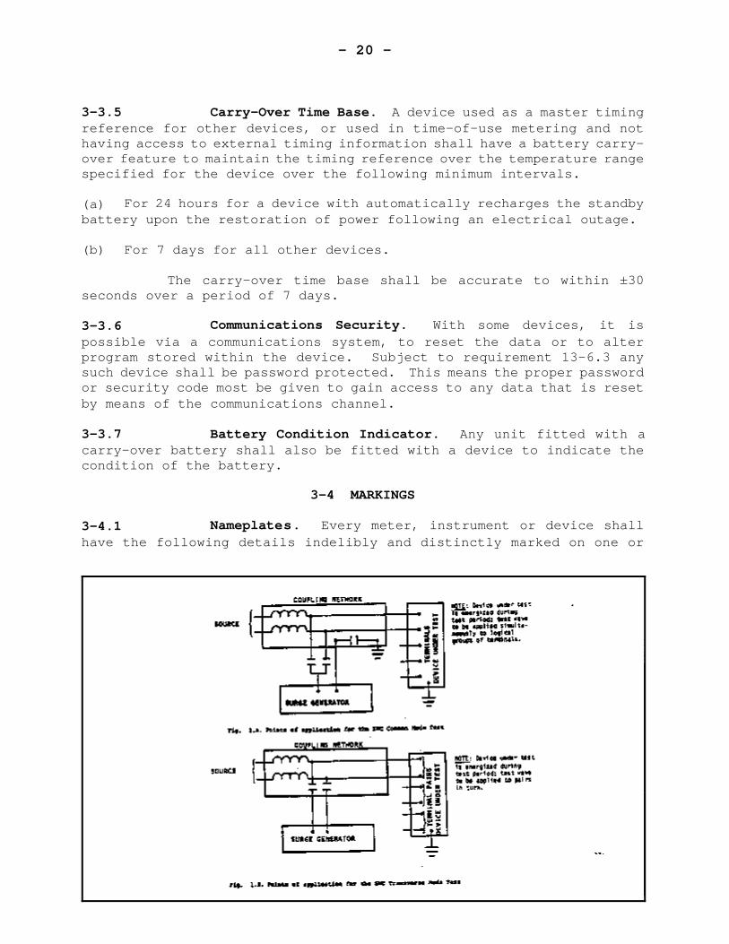
3-3.4.3 Surge Withstand Capability (SWC) Test. The SWC testshall only be performed on solid state devices having circuits rated at40V or more.
The SWC test wave shall be an oscillatory wave of frequency rangefrom 1.0 MHZ to 1.5 MHZ with a voltage range from 2.5 kV to 3.0 kV crestvalue of the first cycle peak, and having an envelope decaying to 50%of the crest value of the first peak in not less than 6 microsecondsfrom the start of the wave.
The source impedance of the surge generator used to produce thetest wave shall be 150 ohms. The test wave shall be applied to the testspecimen at a repetition rate of not less than 50 tests per second fora period of not less than 2.0 seconds.
For the duration of the test the meter or device shall beconnected or energized in its normal configuration. The input voltageand supply circuits shall be energized at approximately 20% of ratedmaximum current.
Schematics indicating points of application are shown in Fig. 1.
Note: Further details of this SWC test may be found in IEEE Std.472/ANSI C37.90 a.
- 20 -
3-3.5 Carry-Over Time Base. A device used as a master timingreference for other devices, or used in time-of-use metering and nothaving access to external timing information shall have a battery carry-over feature to maintain the timing reference over the temperature rangespecified for the device over the following minimum intervals.
(a) For 24 hours for a device with automatically recharges the standbybattery upon the restoration of power following an electrical outage.
(b) For 7 days for all other devices.
The carry-over time base shall be accurate to within ±30seconds over a period of 7 days.
3-3.6 Communications Security. With some devices, it ispossible via a communications system, to reset the data or to alterprogram stored within the device. Subject to requirement 13-6.3 anysuch device shall be password protected. This means the proper passwordor security code most be given to gain access to any data that is resetby means of the communications channel.
3-3.7 Battery Condition Indicator. Any unit fitted with acarry-over battery shall also be fitted with a device to indicate thecondition of the battery.
3-4 MARKINGS
3-4.1 Nameplates. Every meter, instrument or device shallhave the following details indelibly and distinctly marked on one or
- 21 -
more nameplates attached in such a way as to be clearly visible from thefront, with all covers in place:
I) Name or mark of manufacturer ii) Type or designationiii) Serial number iv) Departmental approval number*v) Operating temperature range
*Note: These requirements shall only apply if the operating rangeis less than -40°C to +53°C. (i.e. intended for temperature controlledlocations.)
Additional marking requirements applicable to various typesof meters and devices are set forth in subsequent sections specificthereto.
3-4.2 Nameplate Location. It is preferred that the nameplatebe attached to the base or meter mechanism; however, it may be attachedto the cover or scale provided that in such cases, the serial number isalso permanently and predominantly marked on the measuring element orbase. Under no circumstances shall the nameplate be mounted on theterminal cover.
- 22 -
3-5 PERFORMANCE REQUIREMENTS
3-5.1 Reference Conditions for Tests. Except when statedotherwise hereinafter, the following reference test conditions shallapply:
I) the ambient temperature shall be 23°C ±2°C ii) the distortion factors of the supply voltage(s) and
current(s) shall not exceed 2% iii) the supply shall be at rated frequency ±0.2% iv) the voltage shall be the rated voltage ±0.5% v) there shall be no significant external magnetic field vi) all voltage circuits shall be connected in parallel and
all current circuits shall be connected in seriesassisting
vii) before any tests are made the voltage circuits shallhave been energized for at least one hour
viii) test currents shall be set progressively to increasingor decreasing values and the current circuits shall beenergized at each value for a sufficient time to obtainthermal stability
xi) the meter or device shall be in its normal workingcondition. Except where the nature of the testrequires otherwise, all registers, transmittingcontacts, detents, etc., shall be operating in thenormal state. For cyclometer-type registers, only thefastest moving counter shall be turning.
x) for tests to determine the effect of ambienttemperature variation, before commencing tests, themeter shall be subjected to each required value ofambient test temperature for length of time necessaryto establish thermal stability.
3-5.2 EMI Susceptibility.
3-5.2.1 Where so specified in the appropriate section, metersand devices shall be subject to tests to establish susceptibility toelectromagnetic interference (EMI tests). The requirements are setforth in sub-clauses 3-5.2.2 and 3-5.2.3 below.
Further details relating to these tests may be found inMIL-STD-461B.
- 23 -
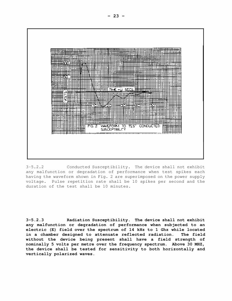
3-5.2.2 Conducted Susceptibility. The device shall not exhibitany malfunction or degradation of performance when test spikes eachhaving the waveform shown in Fig. 2 are superimposed on the power supplyvoltage. Pulse repetition rate shall be 10 spikes per second and theduration of the test shall be 10 minutes.
3-5.2.3 Radiation Susceptibility. The device shall not exhibitany malfunction or degradation of performance when subjected to anelectric (E) field over the spectrum of 14 kHz to 1 Ghz while locatedin a chamber designed to attenuate reflected radiation. The fieldwithout the device being present shall have a field strength ofnominally 5 volts per metre over the frequency spectrum. Above 30 MHZ,the device shall be tested for sensitivity to both horizontally andvertically polarized waves.
- 24 -
3-5.3 Effects of Ambient Temperature. All devices intendedfor outdoor use, i.e. for use in locations lacking temperature control,shall be tested from -40°C to +53°C and shall perform according to therequirements set out in the applicable section of these specifications.
Device intended for temperature controlled locationsshall be tested over the temperature range stated on the nameplate.Where the tolerances set out in subsequent sections of thesespecifications apply to the temperature range of -40° to +53°C, theyshall be prorated according to the range stated on the nameplate fordevices intended for a narrower temperature range.
3-5.4 Reverse Operation. Any indication or registration ofpower or energy shall be in conformance with the direction of the energyflow through the meter. The meter shall be tested over a four hourperiod at maximum load, and any registration or an excess of one pulsegenerated indicating energy flowing in the reverse direction shall notbe permitted.
- 25 -
SECTION 4 - INDUCTION-TYPE WATT HOUR METERS
CONTENTS
PAGE
4-1 SCOPE . . . . . . . . . . . . . . . . . . . . . . . . . . . 24
4-2 MECHANICAL REQUIREMENTS . . . . . . . . . . . . . . . . . . 244-2.1 Rotor . . . . . . . . . . . . . . . . . . . . . . 244-2.2 Registers . . . . . . . . . . . . . . . . . . . . 25
4-3 ELECTRICAL REQUIREMENTS . . . . . . . . . . . . . . . . . . 264-3.1 Connections . . . . . . . . . . . . . . . . . . . 264-3.2 Test Links . . . . . . . . . . . . . . . . . . . 264-3.3 Maximum Rated Current . . . . . . . . . . . . . . 264-3.4 Insulation . . . . . . . . . . . . . . . . . . . 27
4-4 MARKINGS . . . . . . . . . . . . . . . . . . . . . . . . . 27
4-5 PERFORMANCE REQUIREMENTS . . . . . . . . . . . . . . . . . 284-5.1 Reference Conditions for Tests . . . . . . . . . 284-5.2 Test Currents and Test Points . . . . . . . . . . 284-5.3 Adjustment Prior to Tests . . . . . . . . . . . . 294-5.4 Creep . . . . . . . . . . . . . . . . . . . . . . 304-5.5 Load Performance . . . . . . . . . . . . . . . . 304-5.6 Performance of Individual Current Circuits . . . 314-5.7 Polyphase Energization . . . . . . . . . . . . . 324-5.8 Effect of Voltage Variation . . . . . . . . . . . 334-5.9 Starting . . . . . . . . . . . . . . . . . . . . 334-5.10 Effect of Variation of Frequency . . . . . . . . 334-5.11 Effect of Variation of Ambient Temperature . . . 344-5.12 Effect of External Magnetic Field . . . . . . . . 344-5.13 Effect of Momentary Overload . . . . . . . . . . 354-5.14 Effect of Register Friction . . . . . . . . . . . 364-5.15 Effect of Self-Heating . . . . . . . . . . . . . 364-5.16 Effect of Tilt . . . . . . . . . . . . . . . . . 364-5.17 Effect of Current Surge . . . . . . . . . . . . . 364-5.18 Interdependence of Adjustments . . . . . . . . . 37
- 26 -
SECTION 4 - INDUCTION-TYPE WATT HOUR METERS
4-1 SCOPE
These specifications apply to induction-type watt hour meters.
These specifications also apply to components of combinationdevices utilizing the essential elements of induction-type watt hourmeters insofar as their application is practicable.
4-2 MECHANICAL REQUIREMENTS
4-2.1 Rotor
4-2.1.1 Direction of Rotation. Viewed from above, the directionof rotation of the disc shall be counterclockwise. If the disc isvisible from the front of the meter, the direction of rotation shall beclearly indicated by an arrow.
4-2.1.2 Markings
4-2.1.2.1 Markings for Rotation Counting. If the disc is visiblefrom the front of the meter, the edge and upper surface of the discshall carry a conspicuous permanent mark. A companion mark, known asa rotation index mark shall be located on the nameplate, register, frameor magnet in such a manner as to facilitate revolution counting. Othermarks may be added for stroboscopic or other tests, but such marks shallbe so placed as to not interfere with the use of the main visible marksfor revolution counting.
4-2.1.2.2 On self-contained single-phase meters, the disc shallcarry the following markings, in black:
- 27 -
On the upper periphery, one hundred divisions, with every fifthdivision longer than the others, and every tenth division identifiedconsecutively by the figures 10, 20, ... 90.
4-2.1.3 Provision for Photoelectric Testing. For single phasemeters, two holes in the rotor disc shall be provided for photoelectriccalibration. These shall be 180 degrees apart and at equal distancefrom the disc centre. If possible, the arrangement shall be such as topermit photo-electric testing with cover in place. For polyphase andcombination meters this same provision is desirable but not mandatory.
4-2.2 Registers.
4-2.2.1 Register Ratio. The register indication shall bestrictly in accord with the result computed from the number of discrevolutions, the disc constant as given on the nameplate and with themultiplier.
The register ratio shall be permanently marked on the register insuch a manner that it is legible without removing the register. Ifsufficient space is available, the register ratio shall be marked on theregister faceplate.
4-2.2.2 Number of Dials or Drums. Self contained single-phasemeters with a maximum rated current of 100 A or larger shall, exclusiveof the test dial, have 4 dials plus a multiplier or shall have 5 dialswith or without a multiplier.
4-2.2.3 Test Dials. With the exception of meters with a multi-rate register, all single phase meters shall be provided with a specialtest dial for testing the register. In the case of polyphase meters,if the lowest reading dial or drum requires more than one hour to makeone complete revolution when the meter under single phase conditionsspecified in 3-5.1 (vi), is running on maximum load or 100 A whicheveris lesser, a test dial shall be provided.
The pointer of the test dial shall rotate at ten times the speedof the lowest reading dial or drum. It shall be located out of linewith the other dials or be distinctly different in appearance. Thereshall be no figures on the test dial but is shall be divided into tenequal divisions. The direction of rotation shall be indicated by meansof an arrow.
- 28 -
4-2.2.4 Backlash. The backlash in a register shall not exceedone-half of a division of the test dial or that dial which indicates thesmallest increments of energy, unless the backlash can be taken up byrunning the meter for not more than 20 seconds at maximum load.
4-3 ELECTRICAL REQUIREMENTS
4-3.1 Connections. The voltage circuit, if connectioninternally, shall be connected on the supply side of the currentcircuit.
4-3.2 Test Links. All self-contained polyphase meters shallbe provided with test links by means of which the voltage circuits maybe isolated from the current circuits for test purposes without removingthe cover.
4-3.3 Maximum Rated Current. The maximum current rating ofthe meter shall not be greater than that imposed by the followingrestriction:
The speed of the disc shall not exceed 120 revolutions per minute.When the meter is operating with maximum current in all current circuitsand with all voltage circuits energized at rated voltage and unity powerfactor. For polyphase meters, the applied voltages and currents shallbe polyphase and balanced.
- 29 -
4-3.4 Insulation. The insulation shall be capable ofwithstanding:
(a) The a.c. voltage test described in subclause 3-3.4.1 using 2.5 kVrms applied between:
I) The grounded parts and coupled current and voltagecircuits, and
ii) The individual current circuits of multiple currentcircuit meters.
(b) The impulse voltage test described in subclause 3-3.4.2 appliedbetween:
I) All line terminals in pairs, andii) The grounded parts and all terminals coupled together.
4-4 MARKINGS
In addition to the requirements of subsection 3-4, every metershall have the following details indelibly and distinctly marked on oneor more nameplates attached in such a way as to be clearly legible fromthe front, with all covers in place.
I) Rated Frequency ii) Rated voltage or voltages iii) Minimum and maximum rated currents iv) Disc constant v) One of the following
1-phase, 2-wire1-phase, 3-wire2-element2½-element wye2½-element delta3-element wye
vi) For single phase transformer type meters, the word“Transformer Type” in red
vii) For transformer rated meters, also1) Primary disc constant2) Current transformer rating, e.g. 1000-5A3) Voltage transformer rating, e.g. 2400-120V
- 30 -
Note 1: Accepted symbols are 2, EL, Y, ) .
Note 2: For 2½ element wye and 3 element meters, rated voltage isphase to neutral voltage.
Space shall be provided for affixing the inspection number.
If the meter is fitted with accessories such as a reverserunning detent, re-transmitting contacts, etc., this shall be specifiedon the nameplate or on an auxiliary plate, and a diagram of connectionsshall be provided if considered necessary by the director. Recognizedsymbols are acceptable.
4-5 PERFORMANCE REQUIREMENTS
4-5.1 Reference Conditions for Tests. Unless stated otherwisehereinafter, adjustment and tests shall be performed under the followingreference conditions:
I) the conditions stated in clause 3-5.1 ii) the meter mounted in its normal working position
with the disc within 0.5° of truly horizontal.
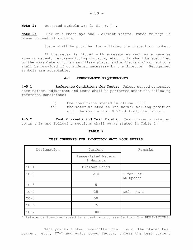
4-5.2 Test Currents and Test Points. Test currents referredto in this and following sections shall be as stated in Table 2.
TABLE 2
TEST CURRENTS FOR INDUCTION WATT HOUR METERS
Designation Current Remarks
Range-Rated Meters% Maximum
TC-1 Minimum Rated
TC-2 2.5 I for Ref.LL Speed*
TC-3 5
TC-4 25 Ref. HL I
TC-5 50
TC-6 75
TC-7 100
* Reference low-load speed is a test point; see Section 2 - DEFINITIONS.
Test points stated hereinafter shall be at the stated testcurrent, e.g., TC-5 and unity power factor, unless the test current
- 31 -
designation is followed by the abbreviation Pf, e.g., TC-5 Pf, and thenthe test power factor shall be 0.5 lag.
4-5.3 Adjustment Prior to Tests. Before commencingperformance tests, the calibration shall be corrected, as nearly aspracticable, to 100% registration.
In addition, polyphase meters shall be adjusted for minimumdifference in registration when each current circuit is energizedseparately (balance test).
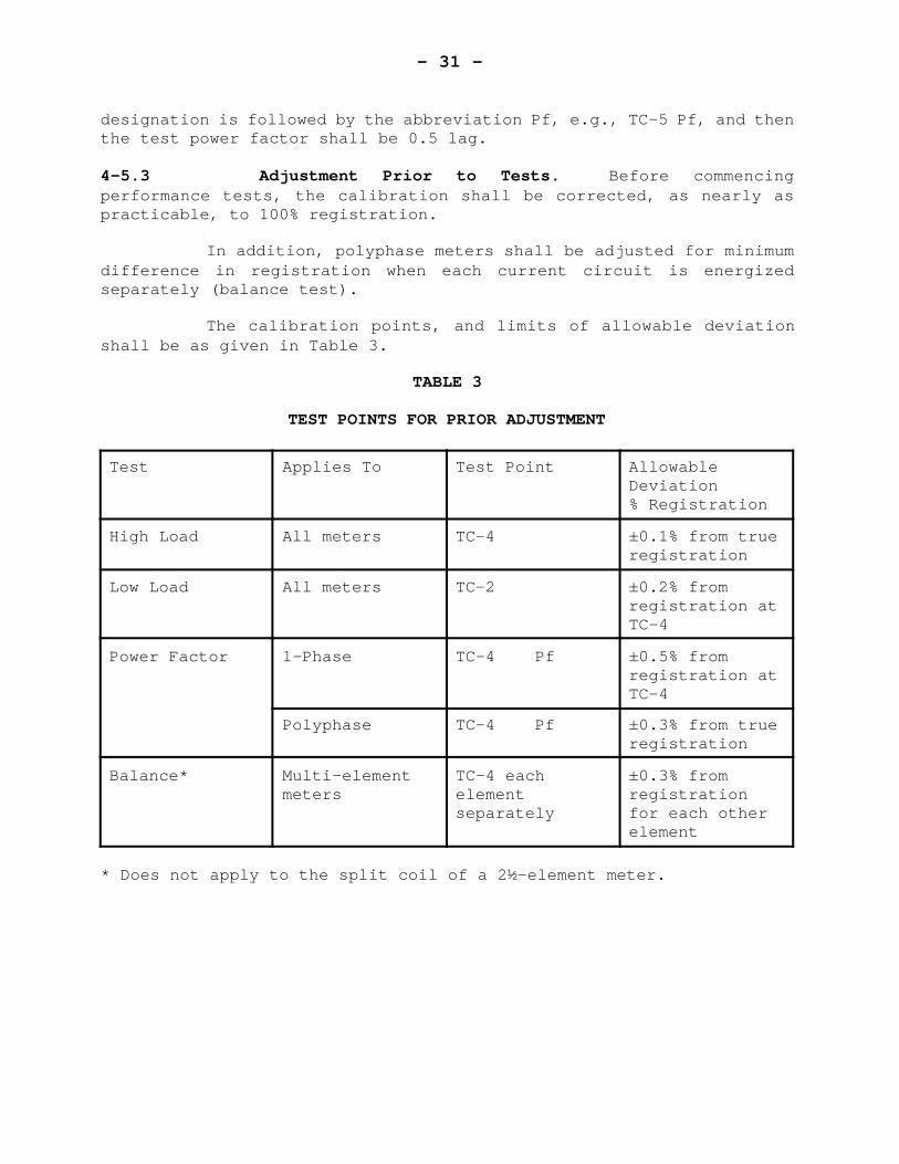
The calibration points, and limits of allowable deviationshall be as given in Table 3.
TABLE 3
TEST POINTS FOR PRIOR ADJUSTMENT
Test Applies To Test Point AllowableDeviation% Registration
High Load All meters TC-4 ±0.1% from trueregistration
Low Load All meters TC-2 ±0.2% fromregistration atTC-4
Power Factor 1-Phase TC-4 Pf ±0.5% fromregistration atTC-4
Polyphase TC-4 Pf ±0.3% from trueregistration
Balance* Multi-elementmeters
TC-4 eachelementseparately
±0.3% fromregistrationfor each otherelement
* Does not apply to the split coil of a 2½-element meter.
- 32 -
4-5.4 Creep. With no current in any current circuit, the discshall not make one complete revolution within a ten minute interval whenany voltage from 80% to 120% of rated voltage is applied. For polyphasemeters, a polyphase voltage of proper phase sequence shall be applied.
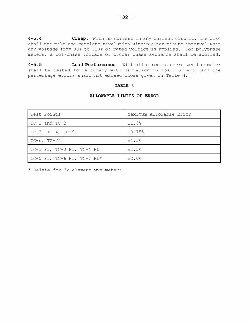
4-5.5 Load Performance. With all circuits energized the metershall be tested for accuracy with variation in load current, and thepercentage errors shall not exceed those given in Table 4.
TABLE 4
ALLOWABLE LIMITS OF ERROR
Test Points Maximum Allowable Error
TC-1 and TC-2 ±1.5%
TC-3, TC-4, TC-5 ±0.75%
TC-6, TC-7* ±1.5%
TC-2 Pf, TC-3 Pf, TC-4 Pf ±1.5%
TC-5 Pf, TC-6 Pf, TC-7 Pf* ±2.0%
* Delete for 2½-element wye meters.
- 33 -
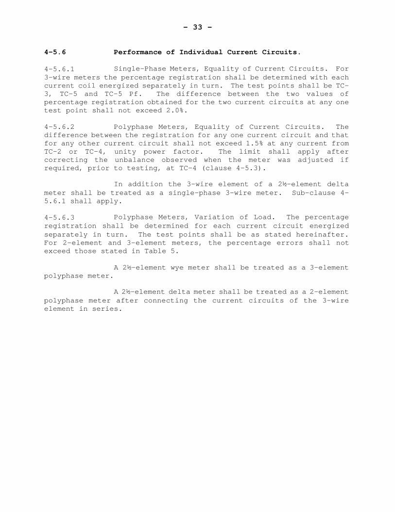
4-5.6 Performance of Individual Current Circuits.
4-5.6.1 Single-Phase Meters, Equality of Current Circuits. For3-wire meters the percentage registration shall be determined with eachcurrent coil energized separately in turn. The test points shall be TC-3, TC-5 and TC-5 Pf. The difference between the two values ofpercentage registration obtained for the two current circuits at any onetest point shall not exceed 2.0%.
4-5.6.2 Polyphase Meters, Equality of Current Circuits. Thedifference between the registration for any one current circuit and thatfor any other current circuit shall not exceed 1.5% at any current fromTC-2 or TC-4, unity power factor. The limit shall apply aftercorrecting the unbalance observed when the meter was adjusted ifrequired, prior to testing, at TC-4 (clause 4-5.3).
In addition the 3-wire element of a 2½-element deltameter shall be treated as a single-phase 3-wire meter. Sub-clause 4-5.6.1 shall apply.
4-5.6.3 Polyphase Meters, Variation of Load. The percentageregistration shall be determined for each current circuit energizedseparately in turn. The test points shall be as stated hereinafter.For 2-element and 3-element meters, the percentage errors shall notexceed those stated in Table 5.
A 2½-element wye meter shall be treated as a 3-elementpolyphase meter.
A 2½-element delta meter shall be treated as a 2-elementpolyphase meter after connecting the current circuits of the 3-wireelement in series.
- 34 -
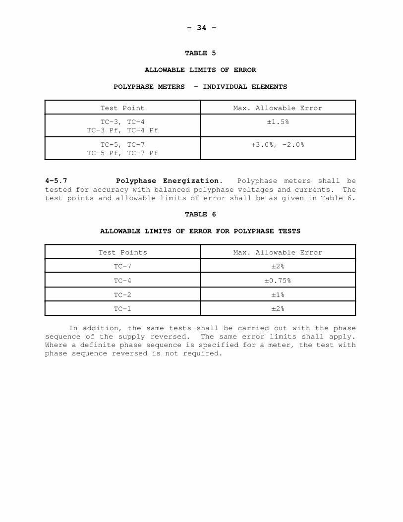
TABLE 5
ALLOWABLE LIMITS OF ERROR
POLYPHASE METERS - INDIVIDUAL ELEMENTS
Test Point Max. Allowable Error
TC-3, TC-4TC-3 Pf, TC-4 Pf
±1.5%
TC-5, TC-7TC-5 Pf, TC-7 Pf
+3.0%, -2.0%
4-5.7 Polyphase Energization. Polyphase meters shall betested for accuracy with balanced polyphase voltages and currents. Thetest points and allowable limits of error shall be as given in Table 6.
TABLE 6
ALLOWABLE LIMITS OF ERROR FOR POLYPHASE TESTS
Test Points Max. Allowable Error
TC-7 ±2%
TC-4 ±0.75%
TC-2 ±1%
TC-1 ±2%
In addition, the same tests shall be carried out with the phasesequence of the supply reversed. The same error limits shall apply.Where a definite phase sequence is specified for a meter, the test withphase sequence reversed is not required.
- 35 -
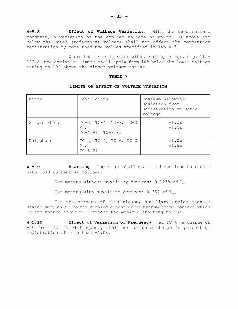
4-5.8 Effect of Voltage Variation. With the test currentconstant, a variation of the applied voltage of up to 10% above andbelow the rated (reference) voltage shall not affect the percentageregistration by more than the values specified in Table 7.
Where the meter is rated with a voltage range, e.g. 115-120 V, the deviation limits shall apply from 10% below the lower voltagerating to 10% above the higher voltage rating.
TABLE 7
LIMITS OF EFFECT OF VOLTAGE VARIATION
Meter Test Points Maximum AllowableDeviation fromRegistration at Ratedvoltage
Single Phase TC-2, TC-4, TC-7, TC-2Pf,TC-4 Pf, TC-7 Pf
±1.0%±1.5%
Polyphase TC-2, TC-4, TC-6, TC-3Pf,TC-6 Pf
±1.0%±1.5%
4-5.9 Starting. The rotor shall start and continue to rotatewith load current as follows:
For meters without auxiliary devices: 0.125% of Imax
For meters with auxiliary devices: 0.25% of Imax
For the purpose of this clause, auxiliary device means adevice such as a reverse running detent or re-transmitting contact whichby its nature tends to increase the minimum starting torque.
4-5.10 Effect of Variation of Frequency. At TC-4, a change of±5% from the rated frequency shall not cause a change in percentageregistration of more than ±1.0%.
- 36 -
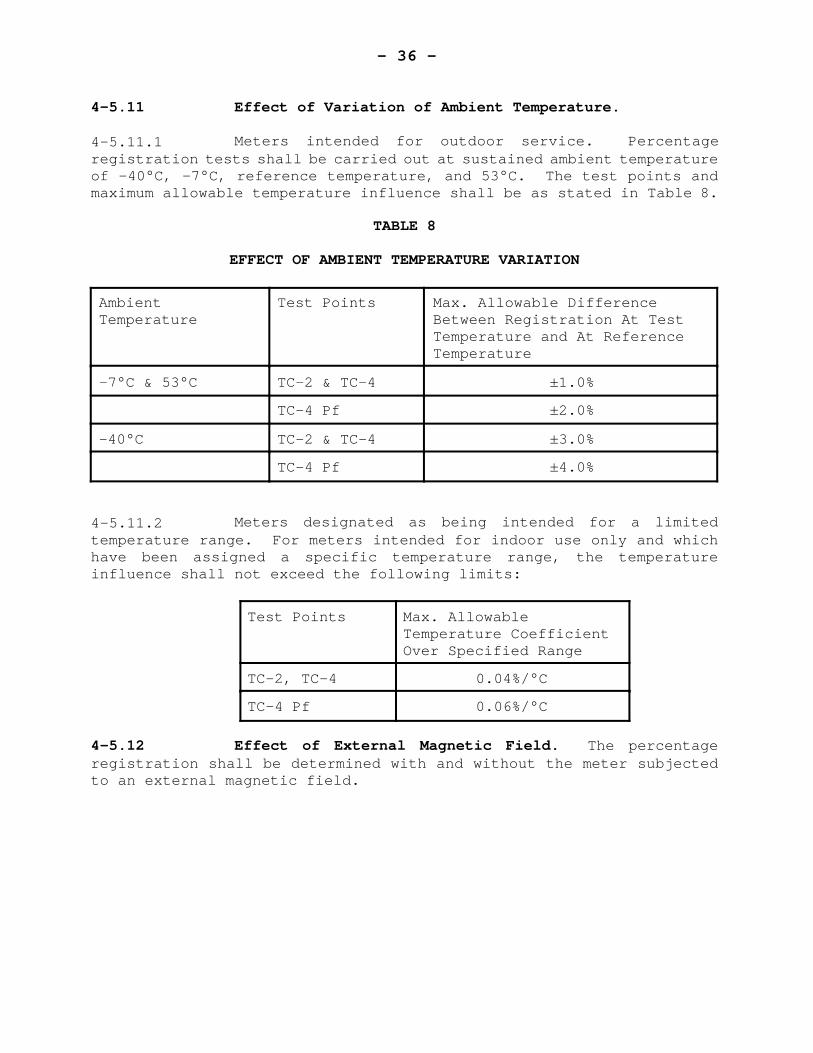
4-5.11 Effect of Variation of Ambient Temperature.
4-5.11.1 Meters intended for outdoor service. Percentageregistration tests shall be carried out at sustained ambient temperatureof -40°C, -7°C, reference temperature, and 53°C. The test points andmaximum allowable temperature influence shall be as stated in Table 8.
TABLE 8
EFFECT OF AMBIENT TEMPERATURE VARIATION
AmbientTemperature
Test Points Max. Allowable DifferenceBetween Registration At TestTemperature and At ReferenceTemperature
-7°C & 53°C TC-2 & TC-4 ±1.0%
TC-4 Pf ±2.0%
-40°C TC-2 & TC-4 ±3.0%
TC-4 Pf ±4.0%
4-5.11.2 Meters designated as being intended for a limitedtemperature range. For meters intended for indoor use only and whichhave been assigned a specific temperature range, the temperatureinfluence shall not exceed the following limits:
Test Points Max. AllowableTemperature CoefficientOver Specified Range
TC-2, TC-4 0.04%/°C
TC-4 Pf 0.06%/°C
4-5.12 Effect of External Magnetic Field. The percentageregistration shall be determined with and without the meter subjectedto an external magnetic field.
- 37 -
The field shall be equivalent to that produced by a coilone meter in diameter having a magnetomotive force of 400 ampere turns.The frequency of the coil current shall be the same as that applied tothe meter. The phase of the coil current and the orientation of thecoil shall be such as to produce a maximum effect. For polyphasemeters, the test voltage and currents shall be balanced polyphase.
The influence of the external magnetic field at TC-4shall not exceed ±2.0%.
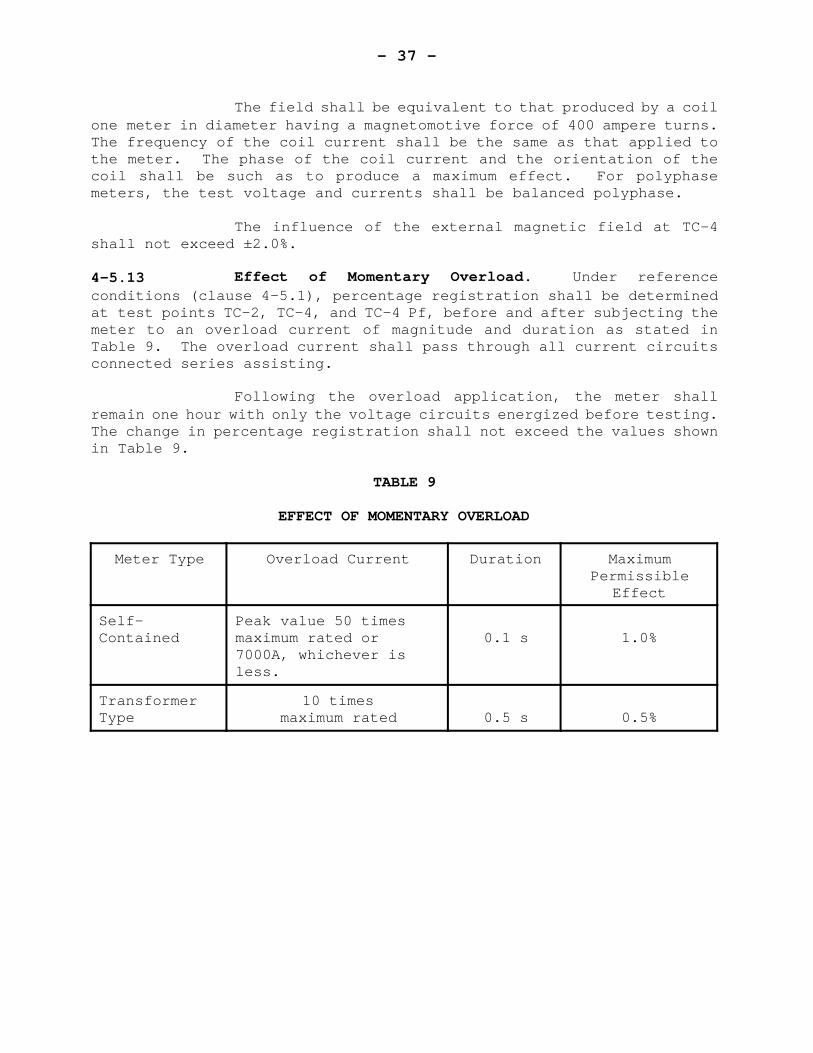
4-5.13 Effect of Momentary Overload. Under referenceconditions (clause 4-5.1), percentage registration shall be determinedat test points TC-2, TC-4, and TC-4 Pf, before and after subjecting themeter to an overload current of magnitude and duration as stated inTable 9. The overload current shall pass through all current circuitsconnected series assisting.
Following the overload application, the meter shallremain one hour with only the voltage circuits energized before testing.The change in percentage registration shall not exceed the values shownin Table 9.
TABLE 9
EFFECT OF MOMENTARY OVERLOAD
Meter Type Overload Current Duration MaximumPermissible
Effect
Self-Contained
Peak value 50 timesmaximum rated or7000A, whichever isless.
0.1 s 1.0%
TransformerType
10 timesmaximum rated 0.5 s 0.5%
- 38 -
4-5.14 Effect of Register Friction. The change in error afterremoval of a clock type register shall not exceed 0.5% at TC-2. Forcyclometer type registers, the maximum effect of friction including thatat turnover through zero, shall not be greater than 1.0% at TC-2.
4-5.15 Effect of Self-Heating. The effect of a sustained loadapplied for four hours shall not change the percentage registration bymore than the following:
TC-4 - ±1.0%
TC-4 Pf - ±1.5%
TC-7 - ±1.0%
The reference registration for these tests shall be theregistration determined within 2 minutes of application of test current.
4-5.16 Effect of Tilt. Tilting a meter up to 3° from thevertical shall not affect the percentage registration at TC-2 by morethan 1.0%.
For test purposes, the four positions of the tilt arespecified as forward, backward, left and right. The position of trueverticality shall be determined by using the plane of the stationarydisc as the reference.
4-5.17 Effect of Current Surge. The meter shall be subjectedto the effects of a transient surge of 20000 A crest, (20 x 50microsecond wave) through a conductor positioned vertically 4 cm behindthe flat position of the base of the meter, with a socket in place. Theeffect of the current surge on the registration at TC-4 shall not exceed±1.0%. This test shall apply only to S-base meters with maximum ratedcurrent 100 A or higher.
- 39 -
4-5.18 Interdependence of Adjustments. Where applicable, makinga light load adjustment sufficient to change the percent registrationat TC-2 by 2% shall not affect the registration at TC-4 Pf by more than0.8%.
Where applicable, making an inductive load adjustmentsufficient to change the percent registration at TC-4 Pf by 1% shall notaffect the registration at TC-2 by more than 0.5%.
- 40 -
SECTION 5 - INDUCTION TYPE VAR HOUR AND Q-HOUR METERS
CONTENTS
PAGE
5-1 SCOPE . . . . . . . . . . . . . . . . . . . . . . . . . . . 39
5-2 CLASSIFICATION . . . . . . . . . . . . . . . . . . . . . . 39
5-3 MECHANICAL REQUIREMENTS . . . . . . . . . . . . . . . . . . 39
5-4 ELECTRICAL REQUIREMENTS . . . . . . . . . . . . . . . . . . 405-4.1 General . . . . . . . . . . . . . . . . . . . . . 405-4.2 Disc and Test Constant . . . . . . . . . . . . . 40
5-5 MARKINGS . . . . . . . . . . . . . . . . . . . . . . . . . 40
5-6 PERFORMANCE REQUIREMENTS FOR CLASS 90 METERS . . . . . . . 40
5-7 PERFORMANCE REQUIREMENTS FOR CLASS 0 OR 60 METERS . . . . . 405-7.1 Reference Conditions for Tests . . . . . . . . . 405-7.2 Test Currents . . . . . . . . . . . . . . . . . . 415-7.3 Adjustment Prior to Tests . . . . . . . . . . . . 415-7.4 Creep . . . . . . . . . . . . . . . . . . . . . . 425-7.5 Performance with Variation Load . . . . . . . . . 425-7.6 Effect of Variation of Voltage . . . . . . . . . 445-7.7 Starting . . . . . . . . . . . . . . . . . . . . 455-7.8 Effect of Variation of Ambient Temperature . . . 455-7.9 Miscellaneous . . . . . . . . . . . . . . . . . . 46
- 41 -
SECTION 5 - INDUCTION TYPE VAR HOUR AND Q-HOUR METERS
5-1 SCOPE
These specifications apply to induction-type var hourand Q-hour meters. These specifications also apply to components ofcombination devices utilizing the essential elements of induction-typevar hour or Q-hour meters.
5-2 CLASSIFICATION
For test purposes, var hour and Q-hour meters shall beclassified by the nominal phase displacement between the voltage andcurrent magnetic fluxes in the principal air gap of a single drivingelement when the voltage and current applied to this single drivingelement are in phase. Var hour and Q-hour meters are generally eitherof class 0, 60, or 90.
Note (1): “Driving element” here includes any necessary accessoryresistors, inductors and shunts.
Note (2): A watt hour meter driving element is class 90.
5-3 MECHANICAL REQUIREMENTS
The requirements of subsections 3-2 and 4-2, whereapplicable, shall apply.
- 42 -
5-4 ELECTRICAL REQUIREMENTS
5-4.1 General. The requirements of subsections 3-3 and 4-3,shall apply.
5-4.2 Disc and Test Constant. For polyphase class 90 var houror Q-hour meter, the ratio of any two constants, kh and Kwh and Ktc, shallbe within 0.10% of the calculated value for an ideal meter.
5-5 MARKINGS
In addition to the requirements of subsections 3-4 and 4-4, everymeter shall have the following details indelibly and distinctly markedin such a way as to be clearly visible from the front, with the coverin place:
I) Var hour and Q-hour disc constant.ii) For class 90 polyphase meters, either
a) single-phase test constant, orb) single-phase watt hour constant, Kwh.
5-6 PERFORMANCE REQUIREMENTS FOR CLASS 90 METERS
For performance tests, class-90° meters shall be treated as watthour meters. Subsection 4-5 shall apply with the following change. Inclause 4-5.2 the abbreviation, Pf, shall signify a test power factor of0.5 lead. The voltage and current sources in such a manner that themeter registers energy in kilowatt hours .
5-7 PERFORMANCE REQUIREMENTS FOR CLASS 0 AND 60 POLYPHASEVAR HOUR AND Q-HOUR METERS
5-7.1 Reference Conditions for Tests. Unless stated otherwisehereafter, adjustment and tests shall be performed under the followingreference conditions:
- 43 -
I) the conditions stated in clause 3-5.1, ii) the meter mounted in its normal working position with the
disc within 0.5° of truly horizontal,iii) the phase displacement between test voltage and test current
to produce maximum torque.
5-7.2 Test Currents. Values given in Table 2 of clause 4-5.2shall apply. Unless stated otherwise the test voltage and current shallhave a phase displacement such as to produce maximum torque1. Where thetest current designation is followed by the abbreviation Pf, e.g. TC-4Pf, the phase displacement between test voltage and test current shallbe such as to produce 50% of maximum torque2.
Note 1: For a class 60 meter the test current would lead the testvoltage by 30°.
Note 2: For a class 60 meter the test current would lag the testvoltage by 30°.
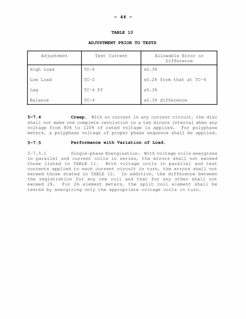
5-73 Adjustment Prior to Tests. Before commencingperformance tests, meters shall be adjusted as nearly as is practicableto 100% registration under reference conditions, and for minimumdifference in registration when each current circuit is energizedseparately. The calibration points and limits of allowable deviationshall be as given in Table 10.
- 44 -
TABLE 10
ADJUSTMENT PRIOR TO TESTS
Adjustment Test Current Allowable Error orDifference
High Load
Low Load
Lag
Balance
TC-4
TC-2
TC-4 Pf
TC-4
±0.3%
±0.2% from that at TC-4
±0.3%
±0.3% difference
5-7.4 Creep. With no current in any current circuit, the discshall not make one complete revolution in a ten minute interval when anyvoltage from 80% to 120% of rated voltage is applied. For polyphasemeters, a polyphase voltage of proper phase sequence shall be applied.
5-7.5 Performance with Variation of Load.
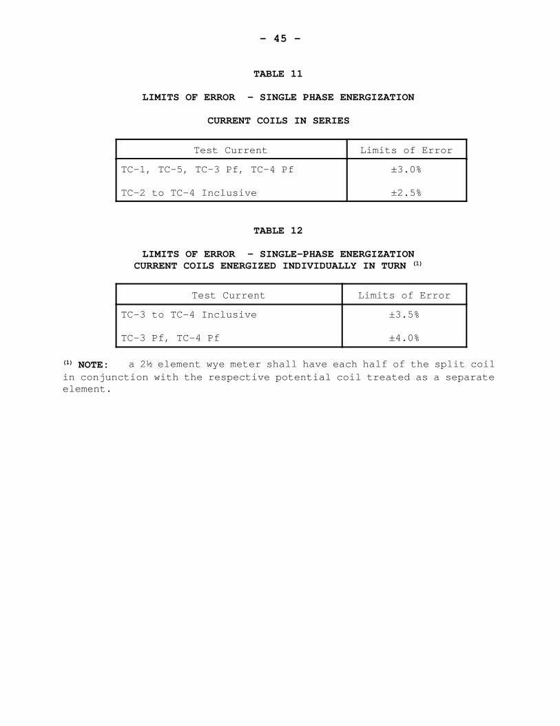
5-7.5.1 Single-phase Energization. With voltage coils energizesin parallel and current coils in series, the errors shall not exceedthose listed in TABLE 11. With voltage coils in parallel and testcurrents applied to each current circuit in turn, the errors shall notexceed those stated in TABLE 12. In addition, the difference betweenthe registration for any one coil and that for any other shall notexceed 2%. For 2½ element meters, the split coil element shall betested by energizing only the appropriate voltage coils in turn.
- 45 -
TABLE 11
LIMITS OF ERROR - SINGLE PHASE ENERGIZATION
CURRENT COILS IN SERIES
Test Current Limits of Error
TC-1, TC-5, TC-3 Pf, TC-4 Pf
TC-2 to TC-4 Inclusive
±3.0%
±2.5%
TABLE 12
LIMITS OF ERROR - SINGLE-PHASE ENERGIZATIONCURRENT COILS ENERGIZED INDIVIDUALLY IN TURN (1)
Test Current Limits of Error
TC-3 to TC-4 Inclusive
TC-3 Pf, TC-4 Pf
±3.5%
±4.0%
(1) NOTE: a 2½ element wye meter shall have each half of the split coilin conjunction with the respective potential coil treated as a separateelement.
- 46 -
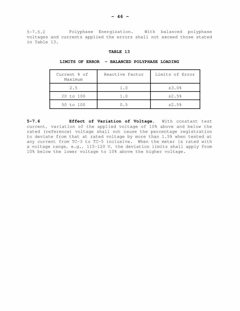
5-7.5.2 Polyphase Energization. With balanced polyphasevoltages and currents applied the errors shall not exceed those statedin Table 13.
TABLE 13
LIMITS OF ERROR - BALANCED POLYPHASE LOADING
Current % of Maximum
Reactive Factor Limits of Error
2.5 1.0 ±3.0%
20 to 100 1.0 ±2.5%
50 to 100 0.5 ±2.5%
5-7.6 Effect of Variation of Voltage. With constant testcurrent, variation of the applied voltage of 10% above and below therated (reference) voltage shall not cause the percentage registrationto deviate from that at rated voltage by more than 1.5% when tested atany current from TC-3 to TC-5 inclusive. When the meter is rated witha voltage range, e.g., 115-120 V, the deviation limits shall apply from10% below the lower voltage to 10% above the higher voltage.
- 47 -
5-7.7 Starting. The rotor shall start, and continue to rotatewith currents as follows:
For meters without auxiliary devices: 0.1% of Imax.
For meters with auxiliary devices: 0.2% of Imax
For the purpose of this clause, auxiliary device meansa device such as a reverse running detent or re-transmitting contactwhich by its nature tends to increase the minimum starting torque.
5-7.8 Effect of Variation of Ambient Temperature.
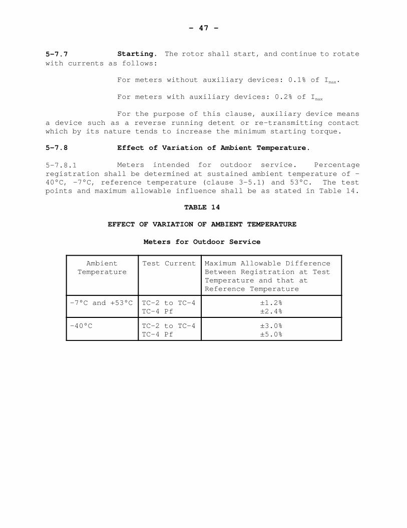
5-7.8.1 Meters intended for outdoor service. Percentageregistration shall be determined at sustained ambient temperature of -40°C, -7°C, reference temperature (clause 3-5.1) and 53°C. The testpoints and maximum allowable influence shall be as stated in Table 14.
TABLE 14
EFFECT OF VARIATION OF AMBIENT TEMPERATURE
Meters for Outdoor Service
AmbientTemperature
Test Current Maximum Allowable DifferenceBetween Registration at TestTemperature and that atReference Temperature
-7°C and +53°C TC-2 to TC-4TC-4 Pf
±1.2%±2.4%
-40°C TC-2 to TC-4TC-4 Pf
±3.0%±5.0%
- 48 -
5-7.8.2 Meters designated as being intended for a limitedtemperature range.
For meters intended for indoor use only and which havebeen assigned a specific temperature range, the temperature coefficientshall not exceed 0.15% per °C at any current from TC-2 to TC-7 or 0.25%per °C at any current from TC-3 to TC-7 Rf.
5-7.9 Miscellaneous. The requirements of clauses 4-5.12 to4-5.17, inclusive, shall apply, bearing in mind the provisions of clause5-7.2.
- 49 -
SECTION 6 - STATIC INTEGRATING METERS
CONTENTS
PAGE
6-1 SCOPE . . . . . . . . . . . . . . . . . . . . . . . . . . . 48
6-2 ELECTRICAL REQUIREMENTS6-2.1 Power Supply . . . . . . . . . . . . . . . . . . 486-2.2 Testing . . . . . . . . . . . . . . . . . . . . . 48
6-3 MARKINGS . . . . . . . . . . . . . . . . . . . . . . . . . 496-3.1 Constants . . . . . . . . . . . . . . . . . . . . 496-3.2 Meters Compensated for Line or Transformers Losses 49
6-4 PERFORMANCE REQUIREMENTS . . . . . . . . . . . . . . . . . 496-4.1 Reactive Energy Meters . . . . . . . . . . . . . 496-4.2 Adjustments Prior to Tests . . . . . . . . . . . 496-4.3 Reading to Zero Load . . . . . . . . . . . . . . 496-4.4 Load Performance . . . . . . . . . . . . . . . . 496-4.5 Performance of Individual Current Circuits . . . 506-4.6 Polyphase Energization . . . . . . . . . . . . . 516-4.7 Effect of Voltage Variation . . . . . . . . . . . 516-4.8 Starting . . . . . . . . . . . . . . . . . . . . 516-4.9 Effect of Variation of Frequency . . . . . . . . 516-4.10 Effect of Variation of Ambient Temperature . . . 526-4.11 Effect of External Magnetic Field . . . . . . . . 526-4.12 Effect of Momentary Overload . . . . . . . . . . 526-4.13 Effect of Self-Heating . . . . . . . . . . . . . 536-4.14 EMI Susceptibility . . . . . . . . . . . . . . . 53
- 50 -
SECTION 6 - STATIC INTEGRATING METERS
6-1 SCOPE
These specifications apply to solid state energy meterssuch as watt hour, var hour, and Q-hour meters.
This specification is written to pertain to devices ofthis nature which are designed for use with instrument transformers.Should similar devices intended for direct connection be submitted theywill be considered in the light of this and other related sections, duediscretion being used in the application of the various clauses.
6-2 ELECTRICAL REQUIREMENTS
6-2.1 Power Supply. Preferred power supply rating is 120 V,60Hz.
6-2.2 Testing. Each meter shall be provided with a testingmeans to facilitate calibration, (in a manner analogous to counting thedisc revolutions of an induction watt hour meter).
Such testing means shall provide at least 5 pulses (orother indications) per minute when the meter is operating at 25% ofmaximum load under the single phase reference conditions specified inclause 3-5.1.
- 51 -
6-3 MARKINGS
6-3.1 Constants. Markings shall be as set forth in subsection4-4 except that for “disc constant”, “test constant” shall besubstituted.
6-3.2 Meters Compensated for Line or Transformer Losses.Meters which are internally compensated for line or transformer lossesshall have “LOSS COMPENSATED” indelibly marked in red on the nameplate.
6-4 PERFORMANCE REQUIREMENT
6-4.1 Reactive Energy Meters. For reactive energy meters,where the term “power factor” appears in this subsection, the term“reactive factor” shall be substituted.
6-4.2 Adjustments Prior to Tests. Before commencingperformance tests, the meter shall be adjusted for minimum errors at thefollowing test points:
I) 25% Imax at unity power factor. ii) 25% Imax at 0.5 power factor.iii) 2.5% Imax at unity power factor.
In addition, polyphase meters shall be adjusted suchthat the difference in error between any two elements is minimal at 25%Imax.
6-4.3 Reading at Zero Load. With rated voltage and zerocurrent applied and under steady state conditions, there shall be nochange in the meter reading over a four hour period.
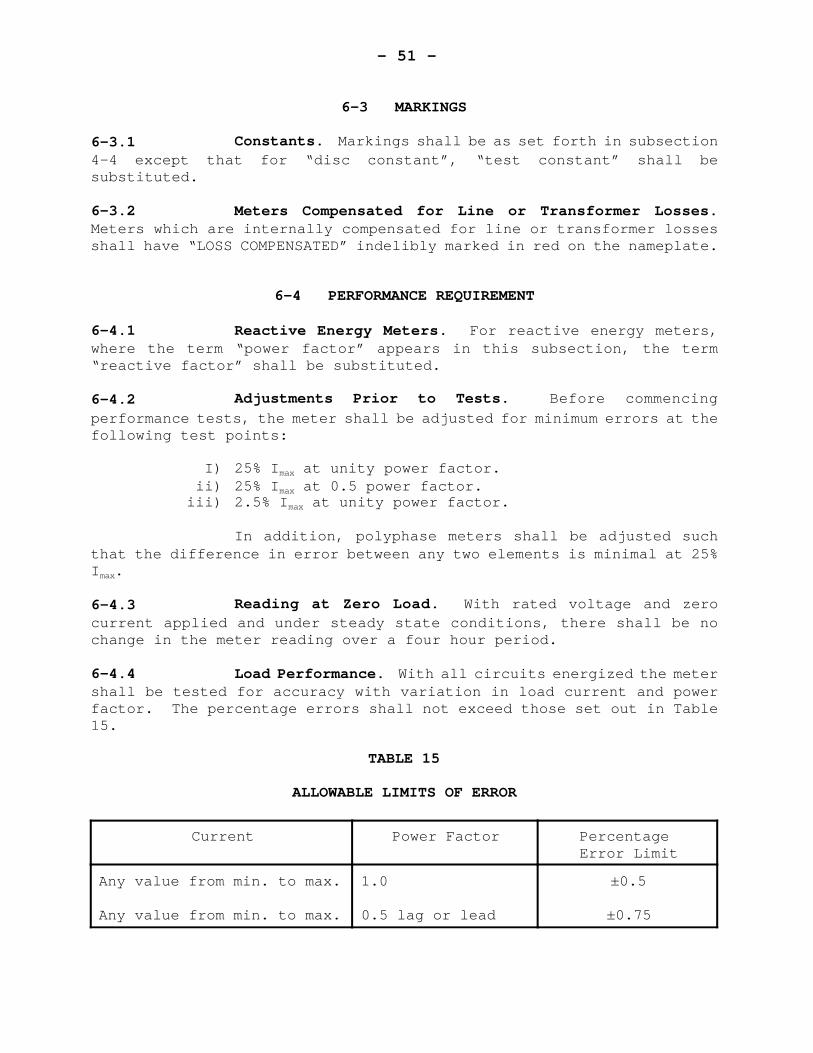
6-4.4 Load Performance. With all circuits energized the metershall be tested for accuracy with variation in load current and powerfactor. The percentage errors shall not exceed those set out in Table15.
TABLE 15
ALLOWABLE LIMITS OF ERROR
Current Power Factor Percentage Error Limit
Any value from min. to max.
Any value from min. to max.
1.0
0.5 lag or lead
±0.5
±0.75
- 52 -
6-4.5 Performance of Individual Current Circuits.
6-4.5.1 Single-Phase Meters, Equality of Current Circuits. For3-wire meters the percentage registration shall be determined with eachcurrent circuit energized separately in turn. The test points shall be5% Imax, 50% Imax and 50% Imax Pf. The difference between the values ofpercentage registration for each circuit obtained at any one test pointshall not exceed 1.0%.
6-4.5.2 Polyphase Meters, Equality of Current Circuits. Thedifferent between the registration for any one current circuit and thatfor any other current circuit shall not exceed 0.5% at any current from2.5% Imax to 50% Imax inclusive. This limit shall apply after correctingfor the unbalance observed when the meter was adjusted, if required,prior to testing, at 50% Imax (clause 6-4.2).
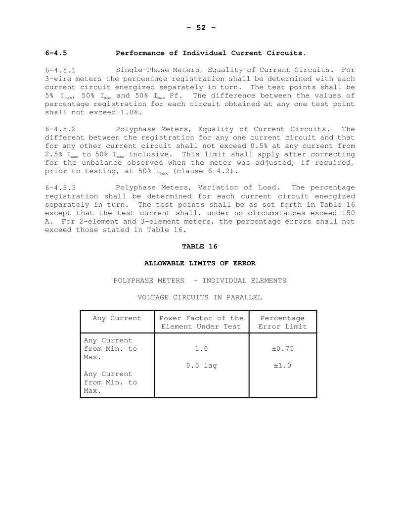
6-4.5.3 Polyphase Meters, Variation of Load. The percentageregistration shall be determined for each current circuit energizedseparately in turn. The test points shall be as set forth in Table 16except that the test current shall, under no circumstances exceed 150A. For 2-element and 3-element meters, the percentage errors shall notexceed those stated in Table 16.
TABLE 16
ALLOWABLE LIMITS OF ERROR
POLYPHASE METERS - INDIVIDUAL ELEMENTS
VOLTAGE CIRCUITS IN PARALLEL
Any Current Power Factor of theElement Under Test
PercentageError Limit
Any Currentfrom Min. toMax.
Any Currentfrom Min. toMax.
1.0
0.5 lag
±0.75
±1.0
- 53 -
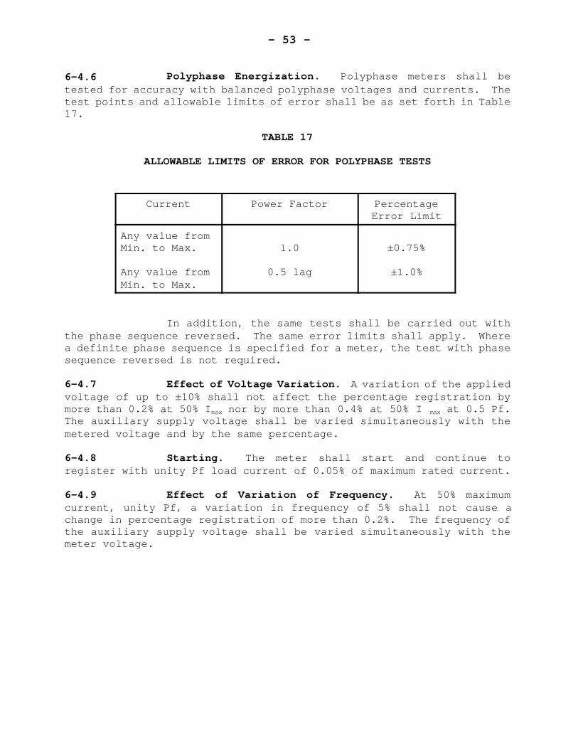
6-4.6 Polyphase Energization. Polyphase meters shall betested for accuracy with balanced polyphase voltages and currents. Thetest points and allowable limits of error shall be as set forth in Table17.
TABLE 17
ALLOWABLE LIMITS OF ERROR FOR POLYPHASE TESTS
Current Power Factor PercentageError Limit
Any value fromMin. to Max.
Any value fromMin. to Max.
1.0
0.5 lag
±0.75%
±1.0%
In addition, the same tests shall be carried out withthe phase sequence reversed. The same error limits shall apply. Wherea definite phase sequence is specified for a meter, the test with phasesequence reversed is not required.
6-4.7 Effect of Voltage Variation. A variation of the appliedvoltage of up to ±10% shall not affect the percentage registration bymore than 0.2% at 50% Imax nor by more than 0.4% at 50% I max at 0.5 Pf.The auxiliary supply voltage shall be varied simultaneously with themetered voltage and by the same percentage.
6-4.8 Starting. The meter shall start and continue toregister with unity Pf load current of 0.05% of maximum rated current.
6-4.9 Effect of Variation of Frequency. At 50% maximumcurrent, unity Pf, a variation in frequency of 5% shall not cause achange in percentage registration of more than 0.2%. The frequency ofthe auxiliary supply voltage shall be varied simultaneously with themeter voltage.
- 54 -
6-4.10 Effect of Variation of Ambient Temperature. The maximumallowable influence on accuracy due to variation of ambient temperatureshall be 0.03% per °C.
This influence shall be determined by comparing theregistration at 50% Imax and at 50% Imax 0.5 Pf at 23°C ambienttemperature with that at -40°C and at 53°C. If the nameplate indicatesa restricted ambient temperature range the requirements will apply onlywithin this range.
6-4.11 Effect of External Magnetic Field. The change inpercentage registration at 50% Imax shall not exceed ±1.0% when the meteris subjected to an external magnetic field. The magnetic field shallbe equivalent to that produced by a coil one metre in diameter havinga magnetomotive force of 400 ampere-turns. The frequency of the coilcurrent is to be the same as that applied to the meter. The phase ofthe coil current and the orientation of the coil shall be such as toproduce the maximum effect. For polyphase meter, the test voltages andcurrents shall be balanced polyphase.
6-4.12 Effect of Momentary Overload. With all potentialcircuits energized and with current circuits connected series assisting,the meter shall be subjected to a current equal to 10 times Imax for 0.5seconds. After the application of this short time over-current, themeter shall be left for one hour with only the potential circuitsenergized following which the meter shall be tested for variation oferror at 50% Imax at unity power factor. The variation in error shallnot exceed ±0.5%.
- 55 -
6-4.13 Effect of Self-Heating. The effect of a sustained loadat maximum rated current, unity Pf for four hours shall not change thepercentage registration by more than 0.3%.
The reference registration for this test shall be thatdetermined within two minutes of application of test current.
6-4.14 EMI Susceptibility. Meters shall be subject to the EMIsusceptibility tests set forth in 3-5.2.
- 56 -
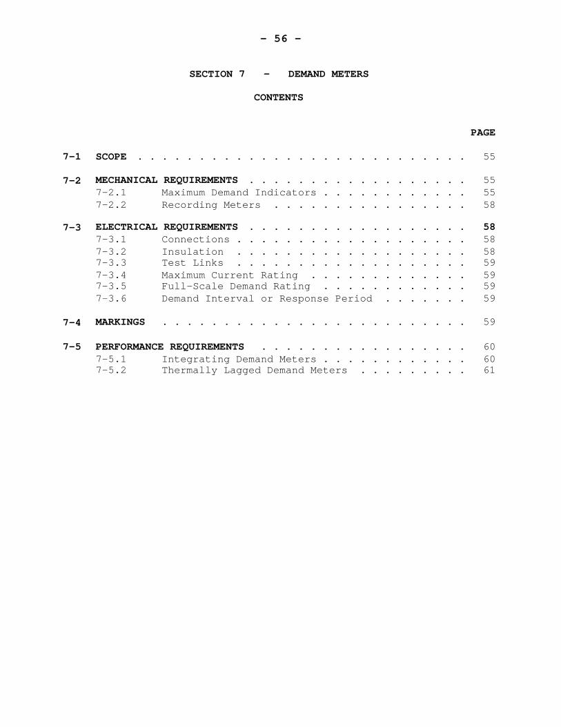
SECTION 7 - DEMAND METERS
CONTENTS
PAGE
7-1 SCOPE . . . . . . . . . . . . . . . . . . . . . . . . . . . 55
7-2 MECHANICAL REQUIREMENTS . . . . . . . . . . . . . . . . . . 557-2.1 Maximum Demand Indicators . . . . . . . . . . . . 557-2.2 Recording Meters . . . . . . . . . . . . . . . . 58
7-3 ELECTRICAL REQUIREMENTS . . . . . . . . . . . . . . . . . . 587-3.1 Connections . . . . . . . . . . . . . . . . . . . 587-3.2 Insulation . . . . . . . . . . . . . . . . . . . 587-3.3 Test Links . . . . . . . . . . . . . . . . . . . 597-3.4 Maximum Current Rating . . . . . . . . . . . . . 597-3.5 Full-Scale Demand Rating . . . . . . . . . . . . 597-3.6 Demand Interval or Response Period . . . . . . . 59
7-4 MARKINGS . . . . . . . . . . . . . . . . . . . . . . . . . 59
7-5 PERFORMANCE REQUIREMENTS . . . . . . . . . . . . . . . . . 607-5.1 Integrating Demand Meters . . . . . . . . . . . . 607-5.2 Thermally Lagged Demand Meters . . . . . . . . . 61
- 57 -
SECTION 7 - DEMAND METERS
7-1 SCOPE
These specifications apply to demand meters ofrecording, lagged or integrating type, used for the measurement ofdemand in watts, volt amperes, vars, or Q*.
They do not apply to transducers, null balancinginstruments, magnetic or paper tape recorders, nor to solid state demandmeters.
7-2 MECHANICAL REQUIREMENTS
7-2.1 Maximum Demand Indicators.
7-2.1.1 Pointer and Scale Indicators.
7-2.1.1.1 General. Where applicable, the clearance between theportion of the pointer which traverses the scale and the scale itselfshall not exceed 2.5 mm nor be less than 1.1 mm.
*Note: Q is a quantity that may be measured by effectively laggingthe applied voltage to a watt meter by 60°.
- 58 -
The driving pointer shall be of a colour distinctlydifferent from that of the driven pointer.
The driving pointer shall not at any time, interferewith clear reading of the driven pointer indication.
7-2.1.1.2 Damping. There shall be sufficient damping to ensurethat when disengaged from the driving pointer, the driven pointer willremain in the correct reading position, unaffected by such vibration asmay be encountered in normal service.
For grease-damped pointers -
(a) With driving and driven pointers in the steady-state in-contact position:
(I) tapping the meter shall not cause theindication to increase by more than 1.0% offull scale.
(ii) removal of the load shall not cause thedriven pointer to be pulled back by morethan l.0% of full scale.
(b) With driving pointer disengaged, tapping the metershall not cause the driven pointer to change position by more than 1%of full scale.
7-2.1.1.3 Reset Device. The device shall be such that, in itsnormal position, it does not affect either the maximum demand indicatoror the driving element. Means shall be provided for sealing the resetdevice in this position. Resetting of the maximum demand indicatorshall only be possible either after breaking the seal or with a specialtool.
- 59 -
It shall not be possible to move the maximum demandindicator up-scale by means of the reset device.
7-2.1.1.4 Reset Time. The reset time shall not exceed 1.0% of thedemand interval, or 15 s whichever is the lesser.
The reset time shall be included in the demand interval.
7-2.1.1.5 Scales. Minimum scale length shall be as follows:
For thermal meters: 90 mmFor integrating demand meters: 150 mm.
7-2.1.2 Clock Type Maximum Demand Indicators.
7-2.1.2.1 General. All clock-type indicators shall have at leastthree dials.
The minimum diameter of clock dial circles shall be 10mm.
Each dial shall be divided into ten equal and clearlynumbered divisions. Preferably dials shall be distinctly separated fromeach other. The lowest reading dial shall be on the right and shallrotate in a clockwise direction viewed from the front. The gearingshall be such that a complete revolution of any pointer shall cause theadjacent pointer to the left to advance one division.
7-2.1.2.2 Cumulative Clock-Type Maximum Demand Indicators.
Cumulative Clock-Type indicators shall have at leastfour dials.
The value represented by the smallest division of thedial with the fastest moving pointer shall not be more than one percentof full scale.
- 60 -
7-2.1.3 Cyclometer-Type Maximum Demand Indicators.
7-2.1.3.1 General. All cyclometer-type demand indicators shallhave at least three digits.
All windows in the demand indicator face shall lie ina straight horizontal line and be of the same size. The size and shapeof the numerals shall be such that they are clearly legible.
The arrangement of the cyclometer drums and the cutoutsin the demand-indicator face shall be such that, with the exception ofthe fastest moving drum, one and only one digit is in full view at alltimes except when the drum is advancing from one position to the next.
7-2.1.3.2 Cumulative Cyclometer-Type Maximum Demand Indicators.All cumulative-type demand indicators shall have at least four digits.
The value represented by the lowest value digit (righthand viewed from the front) shall not be more than one percent of fullscale.
7-2.2 Recording Meters.
7-2.2.1 Chart width. The minimum chart width shall be 110 mm.
7-2.2.2 Scales. When a recording meter is provided with ascale, the graduation thereon must be essentially identical to those onthe chart.
7-3 ELECTRICAL REQUIREMENTS
7-3.1 Connections. The voltage circuit, if connectedinternally shall be connected on the supply side of the current circuit.
7-3.2 Insulation. The insulation shall meet the requirementsof clause 4-3.4.
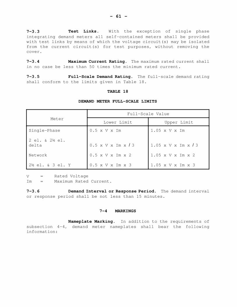
- 61 -
7-3.3 Test Links. With the exception of single phaseintegrating demand meters all self-contained meters shall be providedwith test links by means of which the voltage circuit(s) may be isolatedfrom the current circuit(s) for test purposes, without removing thecover.
7-3.4 Maximum Current Rating. The maximum rated current shallin no case be less than 50 times the minimum rated current.
7-3.5 Full-Scale Demand Rating. The full-scale demand ratingshall conform to the limits given in Table 18.
TABLE 18
DEMAND METER FULL-SCALE LIMITS
MeterFull-Scale Value
Lower Limit Upper Limit
Single-Phase
2 el. & 2½ el.delta
Network
2½ el. & 3 el. Y
0.5 x V x Im
0.5 x V x Im x /3
0.5 x V x Im x 2
0.5 x V x Im x 3
1.05 x V x Im
1.05 x V x Im x /3
1.05 x V x Im x 2
1.05 x V x Im x 3
V = Rated VoltageIm = Maximum Rated Current.
7-3.6 Demand Interval or Response Period. The demand intervalor response period shall be not less than 15 minutes.
7-4 MARKINGS
Nameplate Marking. In addition to the requirements ofsubsection 4-4, demand meter nameplates shall bear the followinginformation:
- 62 -
I) Rated Frequency ii) Rated voltage or voltages iii) Current range or rating iv) Response period or demand interval v) Full-Scale demand rating vi) Single-Phase test constant (if applicable) vii) One of the following:
1-phase, 2-wire1-phase, 3-wire2-element2-element network2-element, 3-phase, 3-wire2½-element wye2½-element delta3-element wye
Note: Accepted symbol are 2, EL, Y, ).
viii) All information essential for determination of thedemand from the meter indication.
ix) For transformer-rated meters;also:(a) Current transformer rating, e.g., CT 1000-5 A(b) Voltage transformer rating, e.g., VT 2400-120 V.
x) For single phase transformer type meters the words“Transformer Type” in red.
If the meter is provided with accessories such as re-transmitting contacts, etc., the nameplate shall so specify and adiagram of connections shall be provided if considered necessary by theDirector.
The marking shall be indelible, distinct, and visible fromoutside the meter with its cover in place.
Space shall be provided for affixing an inspection number.
7-5 PERFORMANCE REQUIREMENTS
7-5.1 Integrating Demand Meters.
- 63 -
7-5.1.1 Energy Measuring Element. The energy measuring elementshall comply with the requirements of section 4 and subsection 4-5,Performance Requirements, with the exception of clause 4-5.14, Effectof Register Friction.
(a) For tests under subsection 4-5 the demandattachment shall be properly couple to the energy measuring element, butwith the demand pointer(s) or drum(s) not being driven by the mechanism.
(b) Effect of Register Friction. The register frictionshall be determined by measuring the change in rotor speed with constantactive power applied from the reference condition of the meter to thecondition with the demand attachment decoupled from the energy measuringelement.
The reference condition shall be that stated in (a)above.
When the demand attachment is decoupled, it shall bemoved only enough to ensure that the coupling gears are just out ofmesh.
At test point TC-2, the register friction shall notexceed 1.5%.
7-5.1.2 Maximum Demand Indicator. For the purpose of approvaltests, performance requirements of block interval demand meters arebased upon the performance of the demand device itself without regardto the accuracy of the watt hour meter with which it is used. Thereforecorrections for any watt hour meter errors that may be involved shallbe applied when computing the demand meter error.
The error of the maximum demand indication at any pointbetween 20% and 90% of full scale shall not exceed 0.75% of full scale.
7-5.2 Thermally Lagged Demand Meters.
7-5.2.1 Reference Conditions and Test Methods. Unless statedotherwise, adjustment and tests shall be performed under the followingreference conditions:
- 64 -
(I) the conditions stated in clause 3-5.1
(ii) unity power factor load.
All loads shall be held constant for a duration of threetimes the response period, and then shall be reduced to zero. Theindication of the driven demand pointer after disengagement of thedriving pointer shall be taken as the meter reading.
7-5.2.2 Adjustment Prior to Tests. Before commencingperformance tests, the damping adjustment if any, shall be set accordingto the manufacturer’s instructions.
Also, the meter error shall be corrected as nearly asis practical to zero, at both zero load and at a major scale divisionat or above 2/3 full scale. For this calibration at a major scaledivision, the driven pointer shall constantly push the driven point toits final position starting from 10% of full scale or lower.
7-5.2.3 Load Performance, Unity Pf. The difference between theindicated or recorded value of the true value, at any load between 20%and 100% of full scale, shall not exceed 1.0% of full scale.
7-5.2.4 Effect of Variation of Power Factor. With a constantload of approximately 60% of full scale applied, changing the powerfactor from unity to 0.8 lag shall not cause a change in meter readingof more than 1.0% of full scale.
7-5.2.5 Performance with Individual Current Circuits. The meterindication shall be determined with all voltage circuits connected inparallel at rated voltage and only one current circuit carrying itsmaximum rated current to give a constant load.
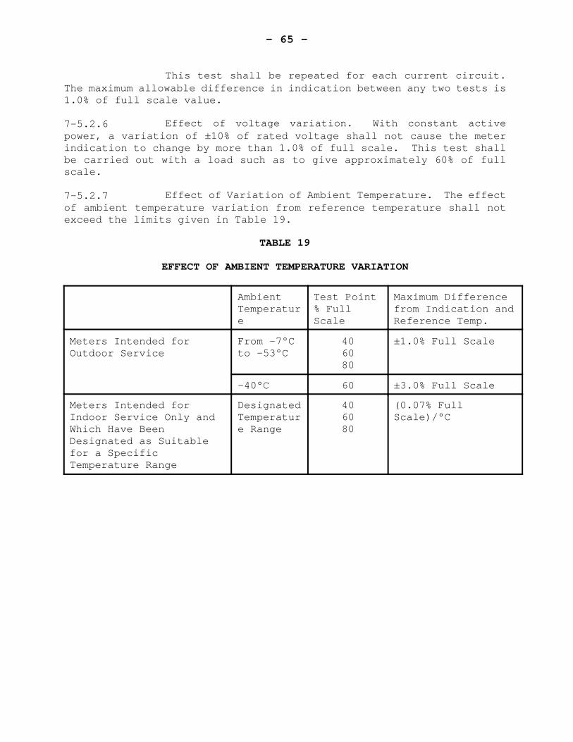
- 65 -
This test shall be repeated for each current circuit.The maximum allowable difference in indication between any two tests is1.0% of full scale value.
7-5.2.6 Effect of voltage variation. With constant activepower, a variation of ±10% of rated voltage shall not cause the meterindication to change by more than 1.0% of full scale. This test shallbe carried out with a load such as to give approximately 60% of fullscale.
7-5.2.7 Effect of Variation of Ambient Temperature. The effectof ambient temperature variation from reference temperature shall notexceed the limits given in Table 19.
TABLE 19
EFFECT OF AMBIENT TEMPERATURE VARIATION
AmbientTemperature
Test Point% FullScale
Maximum Differencefrom Indication andReference Temp.
Meters Intended forOutdoor Service
From -7°Cto -53°C
406080
±1.0% Full Scale
-40°C 60 ±3.0% Full Scale
Meters Intended forIndoor Service Only andWhich Have BeenDesignated as Suitablefor a SpecificTemperature Range
DesignatedTemperature Range
406080
(0.07% FullScale)/°C
- 66 -
7-5.2.8 Effect of Radiated Heat. Radiated heat, applied asfollows, shall not cause a change in the meter reading of more than 1.5%of full scale. This test shall be made at a fixed load givingapproximately 80% full scale. The radiated heat shall be applied froman infra-red heat lamp No. 250R40/1 or equivalent. The lamp shall beheld in any position level with or above the level of the meter for aperiod of not less than 30 minutes and such that the distance betweenthe nearest points of the lamp and the meter is 600 mm. The bulb, (250W) R40, medium base, 115-125 V shall be operated at 250 W.
7-5.2.9 Response Period. The time response characteristic shallbe determined by test, at a load giving approximately 2/3 full scale.The meter reading shall be within the following limits:
I) in one-eighth of the response period, between 10and 30 percent of final reading
ii) in one response period, not more than 92% of finalreading.
- 67 -
SECTION 8 - INDUCTION TYPE LOSS METERS
CONTENTS
PAGE
8-1 SCOPE . . . . . . . . . . . . . . . . . . . . . . . . . . . 66
8-2 MECHANICAL REQUIREMENTS . . . . . . . . . . . . . . . . . . 66
8-3 ELECTRICAL REQUIREMENTS . . . . . . . . . . . . . . . . . . 66
8-4 MARKINGS . . . . . . . . . . . . . . . . . . . . . . . . . 66
8-5 PERFORMANCE REQUIREMENTS . . . . . . . . . . . . . . . . . 678-5.1 Adjustment Prior to Tests . . . . . . . . . . . . 678-5.2 Creep . . . . . . . . . . . . . . . . . . . . . . 688-5.3 Load Performance . . . . . . . . . . . . . . . . 688-5.4 Performance of Individual Current Circuits . . . 688-5.5 Polyphase Energization . . . . . . . . . . . . . 688-5.6 Starting . . . . . . . . . . . . . . . . . . . . 688-5.7 Effect of Variation of Ambient Temperature . . . 688-5.8 Effect of External Magnetic Field . . . . . . . . 688-5.9 Effect of Momentary Overload . . . . . . . . . . 698-5.10 Effect of Register Friction . . . . . . . . . . . 698-5.11 Effect of Self-Heating . . . . . . . . . . . . . 698-5.12 Effect of Tilt . . . . . . . . . . . . . . . . . 69
- 68 -
SECTION 8 - INDUCTION TYPE LOSS METERS
8-1 SCOPE
The requirements of this section apply to transformer-type ampere-square hour (A2·h) meters of the induction type.
8-2 MECHANICAL REQUIREMENTS
Meters shall comply with the requirements of sub-clauses4-2.1.1 and 4-2.2.1.
8-3 ELECTRICAL REQUIREMENTS
The requirements of clauses 4-3.3 and 4-3.4 shall apply.
8-4 MARKINGS
Every meter shall bear, as appropriate, the followinginformation:
I) Rated Frequency ii) Minimum and maximum rated currentsiii) Number of Elements iv) Auxiliary Supply Voltage v) For secondary rated meters, the disc constant in
A2·h per revolution vi) For primary rated meters
1) Current transformer ratio2) Primary line resistance3) Primary disk constant in kW·h per
revolution.
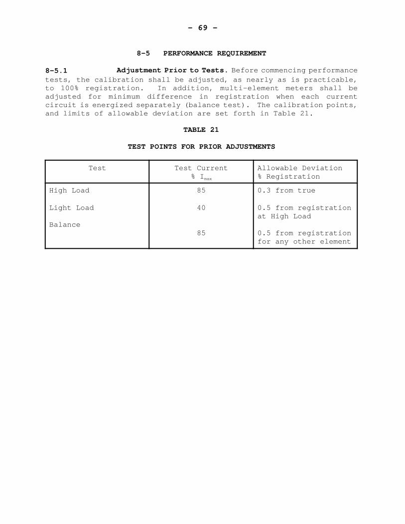
- 69 -
8-5 PERFORMANCE REQUIREMENT
8-5.1 Adjustment Prior to Tests. Before commencing performancetests, the calibration shall be adjusted, as nearly as is practicable,to 100% registration. In addition, multi-element meters shall beadjusted for minimum difference in registration when each currentcircuit is energized separately (balance test). The calibration points,and limits of allowable deviation are set forth in Table 21.
TABLE 21
TEST POINTS FOR PRIOR ADJUSTMENTS
Test Test Current% Imax
Allowable Deviation% Registration
High Load
Light Load
Balance
85
40
85
0.3 from true
0.5 from registrationat High Load
0.5 from registrationfor any other element
- 70 -
8-5.2 Creep. With no current in any current coil, the discshall not make more than one than one revolution within a ten minuteinterval when the compensating element is energized, at any voltage from80% to 120% voltage.
8-5.3 Load Performance. With all circuits energized themeter shall be tested for the effect of variation of load. The errorshall not exceed +2.5% at any current from 30% Imax to 100% Imax.
8-5.4 Performance of Individual Current Circuits. For multi-element meters the percentage registration shall be determined for eachcurrent circuit energized separately in turn. The maximum error at 85%Imax shall not exceed ±2.0%.
8-5.5 Polyphase Energization. Polyphase meters shall betested for accuracy at 85% Imax with balanced polyphase currents. Theregistration shall not differ from that under reference conditions bymore than 0.5%.
8-5.6 Starting. The rotor shall start, and continue torotate with 10% Imax flowing in all current circuits elements.
8-5.7 Effect of Variation of Ambient Temperature. The meantemperature coefficient shall be determined at 85% Imax and shall notexceed 0.5% per °C. This determination shall be made over a temperaturerange of -40°C to +53°C unless a restricted temperature range isspecified in which case the determination shall be made over such range.
8-5.8 Effect of External Magnetic Field. Percentageregistration at 85% Imax shall be determined, with and without the metersubjected to an external magnetic field as set forth in clause 4-5.12.The effect of such field shall not exceed 2.0%.
- 71 -
8-5.9 Effect of Momentary Overload. Percentage registrationat 85% Imax shall be determined before and after subjecting the meter toan overload current of ten times Imax for 0.5 seconds. Current circuitsare to be connected series assisting. Following the overloadapplication the meter is to remain one hour with no current in anycurrent circuit before retesting. The maximum effect of this overloadapplication shall be 1.0%.
8-5.10 Effect of Register Friction. The range in error at 10%Imax, after removal of a clock type register, shall not exceed 1.0%. Forcyclometer type registers, the maximum effect of friction including thata turnover through zero shall be 1.5% at 10% Imax.
8-5.11 Effect of Self-Heating. The effect of a sustained loadequal to Imax for four hours shall not change the percentage registrationby more than 2.0%. The reference registration for this test shall bethat determined within 2 minutes of application of test current.
8-5.12 Effect of Tilt. Tilting the meter up to 3° from thevertical shall not affect the metering error at 40% Imax by more than 2%of true value.
For test purposes, the four positions of the tilt arespecified as forward, backward, left and right. The position of truevertically shall be determined by using the plane of the stationary discas the reference.
- 72 -
SECTION 9 - STATIC LOSS METERS
CONTENTS
PAGE
9-1 SCOPE . . . . . . . . . . . . . . . . . . . . . . . . . . . 71
9-2 ELECTRICAL REQUIREMENTS . . . . . . . . . . . . . . . . . . 71
9-3 MARKINGS . . . . . . . . . . . . . . . . . . . . . . . . . 71
9-4 PERFORMANCE REQUIREMENTS . . . . . . . . . . . . . . . . . 729-4.1 Adjustment Prior to Tests . . . . . . . . . . . 729-4.2 Output at Zero Load . . . . . . . . . . . . . . 729-4.3 Load Performance . . . . . . . . . . . . . . . . 729-4.4 Polyphase Energization . . . . . . . . . . . . . 729-4.5 Starting . . . . . . . . . . . . . . . . . . . . 729-4.6 Effect of Variation of Ambient Temperature . . . 729-4.7 Effect of External Magnetic Field . . . . . . . 739-4.8 Effect of Momentary Overload . . . . . . . . . . 739-4.9 Effect of Self-Heating . . . . . . . . . . . . . 739-4.10 EMI Susceptibility . . . . . . . . . . . . . . . 73
- 73 -
SECTION 9 - STATIC LOSS METERS
9-1 SCOPE
The requirements of this section apply to transformer-type, solid-state ampere-square hour (A2·h) meters.
9-2 ELECTRICAL REQUIREMENTS
The requirements of subsection 6-2 shall apply.
9-3 MARKINGS
Every meter shall bear, as appropriate, the followinginformation:
I) Rated Frequency ii) Rated Voltageiii) Minimum and maximum rated currents iv) Number of elements v) Voltage and frequency of auxiliary supply vi) For secondary - rated meters, the test
constant and pulse constant in A2·h per pulsevii) For primary rated meters
1) Current transformer ratio2) Primary line resistance3) Pulse constant in kW·h per pulse.
- 74 -
9-4 PERFORMANCE REQUIREMENT
9-4.1 Adjustment Prior to Tests. If adjustment are availableexternally with the cover in place the calibration shall be connected,as nearby as is practicable, to zero error before commending tests. Inaddition, multi-element meters shall be adjusted to have minimumdifference in registration between elements when each current circuitis energized singly and in turn.
9-4.2 Output to Zero Load. With rated voltage and zerocurrent the registration shall not increase by more than one divisionof the lowest reading drum, dial or display. Meters with a pulseinitiator shall not produce more than one output pulse.
9-4.3 Load Performance. With all circuits energized, themeter shall be tested for accuracy with variation in load current. Theerrors shall not exceed +1% for any current from 5% Imax to Imax.
9-4.4 Polyphase Energization. Polyphase meters shall betested for accuracy at 50% Imax with balanced polyphase currents. Theregistration shall not differ from that under reference conditions bymore than 0.5%.
9-4.5 Starting. The meter shall start and continue toregister with a current equal to 1%Imax in all circuits.
9-4.6 Effect of Variation of Ambient Temperature. Themaximum allowable influence on accuracy due to variation of ambienttemperature shall be 0.05%/ °C. The determination of this coefficientshall be made at 50%Imax over the temperature range from -40°C to +53°Cunless a restricted temperature range is specified in which case thedetermination shall be made over such range.
- 75 -
9-4.7 Effect of External Magnetic Field. Percentageregistration at 50%Imax shall be determined with and without the metersubjected to an external magnetic field as set forth in 4-5.12. Thechange in registration shall not exceed 1.5%.
9-4.8 Effect of Momentary Overload. Percentage registrationshall be determined at 50%Imax before and after subjecting each currentcircuit singly and in turn to an overload current of 10 x Imax for 0.5seconds. Following this, the meter is to remain one hour beforeretesting. The maximum effect of this overload application shall be0.2%.
9-4.9 Effect of Self-Heating. The effect of a sustained loadequal to Imax through all circuits in series for four hours shall notchange the percent registration by more than 0.5%. The referenceregistration for this test shall be that determined within 2 minutes ofapplication of test current.
9-4.10 EMI Susceptibility. Meters shall be subject to the EMIsusceptibility tests set forth in 3-5.2.
- 76 -
SECTION 10 - TRANSDUCERS
CONTENTS
PAGE
10-1 SCOPE . . . . . . . . . . . . . . . . . . . . . . . . . . . 75
10-2 ELECTRICAL REQUIREMENTS . . . . . . . . . . . . . . . . . . 7510-2.1 Auxiliary Power Supply . . . . . . . . . . . . . 7510-2.2 Preferred Current Rating . . . . . . . . . . . . 75
10-3 MARKINGS . . . . . . . . . . . . . . . . . . . . . . . . . 76
10-4 PERFORMANCE REQUIREMENTS . . . . . . . . . . . . . . . . . 7610-4.1 Reference Conditions for Tests . . . . . . . . . 7610-4.2 Reactive Power Devices . . . . . . . . . . . . . 7710-4.3 Adjustment Prior to Test . . . . . . . . . . . . 7710-4.4 Bi-Directional Transducers . . . . . . . . . . . 7710-4.5 Variation of Load, Unity Power Factor . . . . . 7710-4.6 (Deleted) . . . . . . . . . . . . . . . . . . . 7710-4.7 Power Factor Response . . . . . . . . . . . . . 7710-4.8 Element Balance . . . . . . . . . . . . . . . . 7710-4.9 Input Voltage Variation . . . . . . . . . . . . 7810-4.10 Ambient Temperature Variation . . . . . . . . . 7810-4.11 Variation of External Circuit Resistance . . . . 7810-4.12 Output Ripple . . . . . . . . . . . . . . . . . 7910-4.13 Output at Zero Load . . . . . . . . . . . . . . 7910-4.14 External Magnetic Field . . . . . . . . . . . . 7910-4.15 Effect of Momentary Overload . . . . . . . . . . 7910-4.16 Polyphase Energization . . . . . . . . . . . . . 7910-4.17 Effect of Self-Heating . . . . . . . . . . . . . 8010-4.18 EMI Susceptibility . . . . . . . . . . . . . . . 80
- 77 -
SECTION 10 - TRANSDUCERS
10-1 SCOPE
These specifications apply to devices having a directcurrent (or voltage) output, the value of which is proportional to theac input power, either active power (watts), reactive power (vars), orapparent power (volt-amperes).
The specifications pertain to devices which aredesigned for use in the secondaries of instrument transformers, i.e. for120 V, and currents of less than 10 A. However, devices designed tometer higher voltages and/or currents may also be submitted forapproval. They will be considered in the light of this and otherrelated specifications, due discretion being used in application ofvarious clauses.
10-2 ELECTRICAL REQUIREMENTS
10-2.1 Auxiliary Power Supply. Preferred auxiliary powersupply rating is 120 V, 60 Hz.
10-2.2 Preferred Current Rating. Preferred rated inputcurrent shall be 5 A with maximum rated current of 10 A.
- 78 -
10-3 MARKINGS
Nameplates. In addition to the requirements of clause 3-4nameplates shall bear the following information:
I) Rated Frequency ii) Rated voltage (nominal input value) iii) Rated current (nominal input value) iv) Rated input power (nominal value of input
measured quantity: active, reactive, orapparent power)
v) Maximum rated current (input) if differentfrom rated current
vi) Transfer constant Ka, expressed, for exampleas
Ka = W/mA
vii) One of the following:*1-phase, 2-wire1-phase, 3-wire2-element2½-element wye2½-element delta3-element wye
viii) For a transducer having a current output,the maximum external circuit resistance.
ix) For a voltage output transducer, the minimumexternal circuit resistance.
*Note: Accepted symbols are: 2, EL, Y, ) .
10-4 PERFORMANCE REQUIREMENTS
10-4.1 Reference Conditions for Tests. Except where otherwiseindicated the following standard test conditions shall apply:
I) as appropriate, the conditions stated inclause 3-5.1
ii) the output load resistance shall bea) for current output transducers, 50% ofmaximumb) for voltage output transducers, 150% ofminimum
iii) all circuits shall have been energized for asufficient time to obtain stable output.
- 79 -
10-4.2 Reactive Power Devices. For reactive energy meterswhere the term “power factor” appears in this subsection, the term“reactive factor” is to be substituted.
10-4.3 Adjustment Prior to Tests. If adjustments areavailable externally with cover in place the calibration shall becorrected as nearly as practicable to zero error, both at zero currentinput and at rated input before commencing tests.
10-4.4 Bi-directional Transducers. For bi-directionaltransducers, the requirements which follow, shall, as appropriate, applyfor power flow in either direction.
10-4.5 Variation of Load, Unity Power Factor. With ratedvoltage the error, at any value of current from 1% Imax to Imax shall notexceed 0.5% rated output. If maximum current is not specified thisrequirement shall be based on rated current.
10-4.7 Power Factor Response. With nominal voltage appliedand the input current set to 50%Imax and to Imax, both at 0.5 powerfactor, the device shall be accurate to within ±0.75% of reading.
*Power: active, reactive or apparent.
10-4.8 Element Balance. Polyphase devices shall be testedwith voltage elements in parallel and each current element in turncarrying rated input current at both unity and 0.5 Pf lag.
The maximum difference output between any pair ofelements shall be 0.5% of rated output.
- 80 -
10-4.9 Input Voltage Variation. With a constant input loadapplied, a variation of ±10% of rated input voltage shall not cause theerror to deviate from that at rated voltage by more than 0.25% of ratedoutput.
This test shall be made at approximately 50% ratedoutput and at approximately 90% rated output. The auxiliary powersupply voltage shall be varied simultaneously with the metering voltageand by the same percentage.
10-4.10 Ambient Temperature Variation. The maximum allowableinfluence on accuracy due to variation of ambient temperature shall be0.035% of rated output per °C.
This influence shall be determined by comparing theregistration under reference conditions with that at -40°C and at +53°Cor at the temperature extremes specified on the nameplate, whichever isless.
10-4.11 Variation of External Circuit Resistance.
10-4.11.1 Transducers with current output. With a fixed inputequal to rated input power, variation of the external circuit from zeroup to the maximum shall not change the output by more than 0.25% ratedoutput.
10-4.11.2 Transducers with voltage output. With a fixed inputequal to rated input power variation of the external circuit resistancefrom minimum rated to open circuit shall not cause a change in outputof more than 0.25% rated output.

- 81 -
10-4.12 Output Ripple. The peak to peak value of the ripplecontent in the output shall not exceed 1% of the rated output.
10-4.13 Output at Zero Load. The output at rated voltage andzero current shall not exceed 0.1% of rated output.
10-4.14 External Magnetic Field. The change in output shallnot exceed ±0.5% of rated output when the device is placed in a magneticfield. The field shall be equivalent to that produced by a coil onemetre in diameter having a magnetomotive force of 400 ampere-turns. Thecoil current shall be at the same frequency as that of the device input,but its orientation and phase shall be that which produces maximumeffect. This requirement shall apply from 10% to 100% of rated inputpower.
10-4.15 Effect of Momentary Overload. With rated voltageapplied, the input current circuits shall be energized in series at tentimes the maximum rated current, or ten times rated current if nomaximum is stated, for 3.0 seconds. This overload shall be applied fivetimes with an interval of 5 minutes between successive applications.Following the fifth application, the transducer shall remain for onehour with rated voltage and no current before retesting. This overloadtest shall not cause a change in the output at rated input of more than0.1% of rated output.
10-4.16 Polyphase Energization. Polyphase transducers shall betested for accuracy with balanced polyphase voltage and currents. Testpoints and allowable limits of error shall be as set forth below:
Current Power Factor PercentageError Limit
Any value frommin. to max.
Any value frommin. to max.
1.0
0.5 lag
±0.75%
±1.0%
- 82 -
In addition, the same tests shall be carried out withthe phase sequence reversed. The same error limits shall apply. Wherea definite phase sequence is specified for the transducer, the test withreversed phase sequence is not required.
10-4.17 Effect of Self-Heating. The application for four hoursof rated voltage, maximum rated input current, and the input power thatprovides rated output shall not change the error by more than 0.3% ofrated output. When a maximum rating is not stated, the rated currentshall be used.
The reference error for this test shall be thatdetermined within two minutes of application of test current.
10-4.18 EMI Susceptibility. Transducers shall be subject tothe EMI susceptibility tests set forth in clause 3-5.2.
- 83 -
SECTION 11 - NULL BALANCING INSTRUMENTS
CONTENTS
PAGE
11-1 SCOPE . . . . . . . . . . . . . . . . . . . . . . . . . . . 82
11-2 MECHANICAL REQUIREMENTS 11-2.1 Indicating Scale . . . . . . . . . . . . . . . . 8211-2.2 Scale and Chart Visibility . . . . . . . . . . . 8211-2.3 Scale Width . . . . . . . . . . . . . . . . . . 8211-2.4 Terminals . . . . . . . . . . . . . . . . . . . 8211-2.5 Sealing . . . . . . . . . . . . . . . . . . . . 82
11-3 ELECTRICAL REQUIREMENTS11-3.1 Range Selection . . . . . . . . . . . . . . . . 83
11-4 NAMEPLATES . . . . . . . . . . . . . . . . . . . . . . . . 83
11-5 PERFORMANCE REQUIREMENTS . . . . . . . . . . . . . . . . . 8411-5.1 Reference Conditions for Tests . . . . . . . . . 8411-5.2 Adjustment Prior to Test . . . . . . . . . . . . 8411-5.3 Test Procedure . . . . . . . . . . . . . . . . . 8411-5.4 Linearity . . . . . . . . . . . . . . . . . . . 8511-5.5 Dead Band . . . . . . . . . . . . . . . . . . . 8511-5.6 Transient Overload . . . . . . . . . . . . . . . 8611-5.7 Span Step-Response Time . . . . . . . . . . . . 8611-5.8 Effect of Variation of Ambient Temperature . . . 8611-5.9 Effect of Interference . . . . . . . . . . . . . 8711-5.10 Effect of External Circuit Resistance . . . . . 8811-5.11 Influence of External Magnetic Field . . . . . . 8811-5.12 Effect of Variation in Operating Power Supply Voltage 89
- 84 -
SECTION 11 - NULL BALANCING INSTRUMENTS
11-1 SCOPE
These specifications apply to indirect-actingelectrical measuring instruments of the automatic null-balancing typeused for the measurement of demand in watts, vars, or volt-amperes.
They also apply to auxiliary devices which may beincluded within the instrument case.
11-2 MECHANICAL REQUIREMENTS
11-2.1 Indicating Scale. For each recorded quantity thereshall be an indicating pointer or digital display. The scale for thepointer shall have graduations similar to those on the chart.
11-2.2 Scale Chart and Visibility. The instrument shall beso designed that the scale and chart may be easily read with the coverclosed. On strip-chart instruments a portion of the most recent recordshall be visible with the cover closed.
11-2.3 Scale Width. Minimum scale width shall be 100 mm.
11-2.4 Terminals. The terminals shall be legibly marked andinformation shall be provided to identify the proper connections.
11-2.5 Sealing. Construction shall be such that access to theworking parts may be prevented by means of a door lock or other suitabledevice.
- 85 -
11-3.1 Range Selection. If a recorder has provision forchanging the range by means of interchangeable range modules, eachmodule shall be clearly identified. Provision shall be made for sealingso that range changing cannot be accomplished without breaking the seal.
11-4 NAMEPLATES
In addition to the requirements of clause 3-4 everyinstrument shall have the following details indelibly and distinctlymarked on one or more nameplates visible from the front with the coverclosed:
I) Voltage and frequency of power supply ii) Designation of the unit of measurement and
multiplier if other than 1.
The following information shall be legibly marked onthe instrument and accessible from the front but need not be visiblewith cover closed:
I) Chart identification number ii) Maximum external resistance iii) Response-time designation: Span step-
response time for single point instrumentsor time per point for multiple pointinstruments
iv) Range of measured quantity.
- 86 -
11-5 PERFORMANCE REQUIREMENTS
11-5.1 Reference Conditions for Tests. Except when otherwiseindicated, the following standard test conditions shall apply:
I) The operating power supply voltage andfrequency shall be the rated value ±0.5%.
ii) External test circuits shall be isolatedfrom ground, and from the operating powersupply. There shall be no potential appliedbetween the test circuit and the instrumentcase.
iii) The chart ink recommended by themanufacturer shall be used.
iv) A resistance equal to 50% of the maximumexternal resistance shall be connectedbetween the test source and the recorderinput terminals.
11-5.2 Adjustment Prior to Tests.
11-5.2.1 Before commencing performance tests it shall beestablished that the chart drive, inking and pen or printing mechanismare in proper operating condition.
11-5.2.2 The instrument shall be set up and all adjustment setin accordance with the manufacturer’s instructions to give minimum errorto zero and at a calibration point near 2/3 full scale.
11-5.3 Test Procedure.
11-5.3.1 Copper wire shall be used for connecting the testsource and the reference standard to the instrument under test.
- 87 -
11-5.3.2 The test source shall be adjusted to bring theindication of the instrument under test to a cardinal scale point. Thisis to be done approaching the balance point from each direction. Fora recorder, the pen mark on the chart shall be used as the instrumentreading; for an indicating meter, the indicating scale shall be used.
11-5.4 Linearity. When the instrument is tested for accuracyunder standard reference conditions, the error, at any cardinal scalepoint, shall not exceed 0.5% of full scale.
11-5.5 Dead Band.
11-5.5.1 Maximum dead band shall be 0.2% of full scale.
11-5.5.2 The method of determining the dead band shall be asfollows:
(a) Connect the reference equipment to the instrumentunder test and set it at a value correspondingapproximately to midspan of the instrument.
(b) Increase the source voltage by an amountcorresponding to approximately 0.5% of span.
(c) Slowly decrease the source voltage until theinstrument reading is exactly the same as theoriginal in step (a). Observe the reading of thereference meter.
(d) Decrease the source voltage by an amountcorresponding to approximately 0.5% of span.
- 88 -
(e) Slowly increase the source voltage until theinstrument reading is exactly the same as theoriginal in step (a). Observe the reading of thereference meter.
(f) The difference between the readings obtained in(c) and in (e), expressed in percent of fullscale, is the dead band.
11-5.6 Transient Overload.
11-5.6.1 Method of Test. The instrument shall be allowed tobalance near one end of the span. An abrupt change in measured signalequivalent to approximately 90 percent of span shall be applied to theinstrument. The amount of overshoot beyond the point of final balanceexpressed in percent of span is the transient overshoot. Test shall berepeated for opposite direction of balancing action.
11-5.6.2 Permissible Value. Maximum permissible transientovershoot shall be 0.2 percent of span.
11-5.7 Span Step-Response Time. An abrupt change in themeasured quantity equivalent to 99% of span shall be applied and theinstrument allowed to balance. The test shall be repeated for oppositedirection of balancing action. The measured span step-response timeshall not differ from the manufacturer’s stated value by more than 10%.
11-5.8 Effect of Variation of Ambient Temperature. Themaximum allowable influence due to variations in ambient temperatureshall not affect the performance of the device by more than the limitsgiven in the following table.
This influence shall be determined by comparing theperformance under reference conditions with that at -40°C and +53°C orat the temperature extremes specified on the nameplate, whichever isless.
- 89 -
Temperature Effect On P e r m i s s i b l e
Limits
Error 0.02% of span per °C Dead Band 0.01% of span per
°C Span step-response time 10% of response time
at 23 °C Transient overshoot 0.01% of span per
°C
11-5.9 Effect of Interference. The maximum allowableinfluence due to interference, as determined by the tests detailedbelow, shall be as follows:
Effect on Max. Allowable Influence in % of span, due to
Common Mode Normal ModeInterference Interference
Error 0.1 0.2
Dead Band 0.1 0.2
11-5.9.1 Common Mode Interference - method of test (Refer toFig. 3). With the instrument balanced at approximately, mid-span,common mode interference shall be artificially introduced by applyingvoltage of operating power supply frequency between each measuringcircuit terminal and the case. This voltage shall be adjustable inmagnitude and shall be applied through a blocking capacitor to preventgrounding the input terminals. Means shall be provided for continuouslyshifting the phase angle of the applied voltage. The rms magnitudeshall be measured by a voltmeter connected between the instrument caseand the measuring circuit terminal.
The rms magnitude of the common mode interferencevoltage shall be adjusted to be equal to the span of the instrument, andthe phase angle varied through 360 degrees.
- 90 -
11-5.9.2 Normal Mode Interference - method of test (Refer toFig. 4). With the instrument balanced at approximately mid-span, normalmode interference shall be artificially introduced by applying a voltageof operating power supply frequency between the measuring circuitterminals. This voltage shall be adjustable in magnitude and isolatedfrom the operating power supply and ground by a suitable transformer.A blocking capacitor shall be used to prevent loading the dc measuredquantity. The r.m.s. magnitude of this voltage shall be measured by avoltmeter connected to the input terminal. Means shall be provided forcontinuously shifting the phase angle of the applied voltage.
The r.m.s. magnitude of the normal mode interferenceshall be adjusted to be 20% of the span and the phase angle shall bevaried through 360 degrees.
11-5.10 Effect of External Circuit Resistance. The effect ofinserting maximum external resistance shall not cause a change (fromreference conditions) exceeding the following limits:
Error 0.15% of span
Dead Band 0.15% of span
Span Step-Response Time 10%
Transient Overshoot Negligible
11-5.11 Influence of External Magnetic Field. The instrumentshall be placed in a magnetic field equivalent to that produced by acoil one metre in diameter having a magnetomotive force of 400 ampere-turns.
- 91 -
The frequency of the coil current shall be the same asthat of the instrument operating power supply. The phase of the coilcurrent and the orientation of the coil shall be adjusted to producemaximum effect. The maximum allowable influence shall be as follows:
I) On instrument accuracy: ±0.6% of spanii) On dead band: ±0.25% of span
11-5.12 Effect of Variation in Operating Power Supply Voltage.A variation in the operating supply voltage of 10% above or below thereference value shall not affect the performance by more than the limitsgiven below:
Effect On Permissible Limits
Error 0.2% of span
Dead Band 0.1% of span
Span step-response time 10%
Transient overshoot 0.2% of span
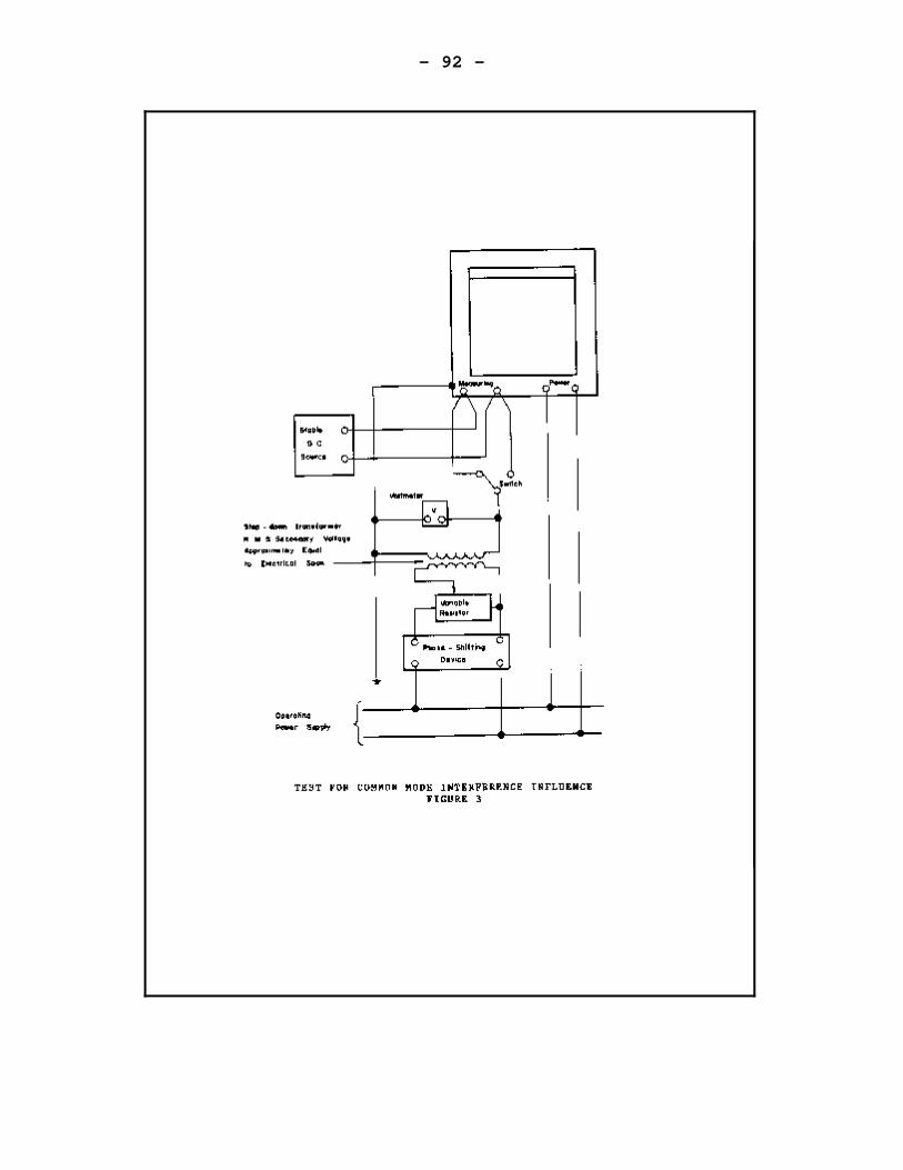
- 92 -
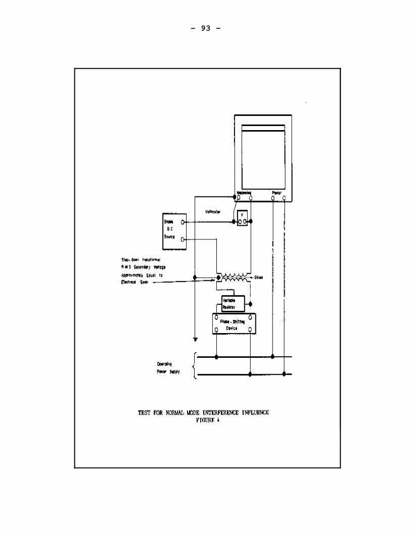
- 93 -
- 94 -
SECTION 12 - PULSE DEVICES
CONTENTS
PAGE
12-1 SCOPE . . . . . . . . . . . . . . . . . . . . . . . . . . . 93
12-2 MECHANICAL REQUIREMENTS . . . . . . . . . . . . . . . . . . 9312-2.1 Reverse detent . . . . . . . . . . . . . . . . 9312-2.2 Mechanical Load . . . . . . . . . . . . . . . . 93
12-3 ELECTRICAL REQUIREMENTS . . . . . . . . . . . . . . . . . . 9312-3.1 Insulation . . . . . . . . . . . . . . . . . . 9312-3.2 Pulse Rate for Demand Measurement . . . . . . . 93
12-4 MARKINGS . . . . . . . . . . . . . . . . . . . . . . . . . 9312-4.1 Pulse Initiators . . . . . . . . . . . . . . . . 9412-4.2 Relays and Pulse Amplifiers . . . . . . . . . . 9412-4.3 Totalizers . . . . . . . . . . . . . . . . . . . 94
12-5 PERFORMANCE REQUIREMENTS . . . . . . . . . . . . . . . . . 9512-5.1 Test Conditions . . . . . . . . . . . . . . . . 9512-5.2 Performance Tests . . . . . . . . . . . . . . . 9512-5.3 Effect of Ambient Temperature . . . . . . . . . 9512-5.4 EMI Susceptibility . . . . . . . . . . . . . . 9512-5.5 Effect of External Magnetic Field . . . . . . . 95
- 95 -
SECTION 12 - PULSE DEVICES
12-1 SCOPE
The requirements of this section shall apply to pulse initiators,relays and totalizers.
12-2 MECHANICAL REQUIREMENTS
12-2.1 Reverse Detent. No pulse initiator shall be fittedto an induction-type meter unless the meter or the initiator isfurnished with a reverse detent.
12-2.2 Mechanical Load. The mechanical load imposed on ameter by a pulse initiator shall be within the adjustment range of themeter. This load shall be as nearly constant as practical through-outthe entire cycle of operation of the pulse initiator.
12-3 ELECTRICAL REQUIREMENTS
12-3.1 Insulation. The requirements of clause 3-3.4 shallapply.
12-3.2 Pulse Rate for Demand Measurement. A pulse initiatorwhich generates pulses intended for use in calculating demand, shallhave a minimum pulse rate of 25 pulses per minute when its host meteris operating at 50% of its maximum load under normal operatingconditions. Approval notices for meters fitted with pulse initiatorswhich do not meet this requirement shall explicitly state that thepulses from the meter are not to be used for calculating demand forrevenue purposes.
12-4 MARKINGS
Devices covered by this section shall be exempt fromthe requirements of clause 3-4.1. The information which shall be marked(if applicable is set out hereunder.
- 96 -
12-4.1 Pulse Initiators (Information may be on initiator orhost meter)
I) Manufacturer’s name or trademark ii) Type identification iii) Type of input (2 or 3 wire) iv) Type of output (2 or 3 wire) v) Voltage and frequency of auxiliary supply (if
applicable) vi) Rate of maximum voltage and frequency (pulses per
unit time) of input pulses vii) Minimum pulse width if critical to operation of
the deviceviii) Connection diagram
12-4.3 Totalizers
I) Manufacturer’s name or trademark ii) Type identification iii) Input to output pulse ratio, (prescalar unit) iv) Number of additive and subtractive elements.
If both are present, each shall be clearlyidentified.
v) Type of input (2 wire or 3 wire) vi) Type of output (2 wire or 3 wire) vii) Voltage and frequency of the auxiliary power
supplyviii) Rated or maximum voltage and frequency
(pulses per unit time) of the input pulses ix) Connection diagram.
- 97 -
12-5 PERFORMANCE REQUIREMENTS
12-5.1 Test Conditions. The device shall be mounted on asupport free form vibration. All tests shall be made at 23oC + 2oC, andat rated voltage and frequency, unless otherwise specified.
The device shall be connected so as to initiate orreceive pulses, or both , and the pulse output shall be connected to acounter for the purpose of recording the total pulses transmitted. Thecounter shall be such that its connection to the device under test shallhave no effect on the device.
12-5.2 Performance Test. The device shall not gain nor losemore than 0.05% of its pulses when operated for at least one hour atmaximum pulse capacity at 85%, 100% and 110% of nameplate voltage. Ifthe device has both an input voltage and supply voltage, both shall bevaried simultaneously and by the same percentage.
12-5.3 Effect of Ambient Temperature. The device shall notgain or lose more than 0.05% of its pulses when operated for at leastone hour at maximum pulse capacity over a temperature range from -40oCto +53oC or at the temperature extremes specified on the nameplate,whichever is less.
12-5.4 EMI Susceptibility. The requirements of clause 3-5.2shall apply.
12-5.5 Effect of External Magnetic Field. The device shall becapable of operating, without degradation of performance in an external60 Hz alternating field. This field shall be equivalent to thatproduced by a coil one metre in diameter having a magnetomotive forceof 400 ampere-turns.
- 98 -
SECTION 13 - PROGRAMMABLE DEVICES AND PULSE RECORDERS
CONTENTS
13-1 SCOPE . . . . . . . . . . . . . . . . . . . . . . . . . . . . . . . . . . . . . . . . . . . . . . . . . . . . . . . . . . . . . . . . . .
13-2 MECHANICAL REQUIREMENTS . . . . . . . . . . . . . . . . . . . . . . . . . . . . . . . . . . . . . . . . . . . . . .13-2.1 Register . . . . . . . . . . . . . . . . . . . . . . . . . . . . . . . . . . . . . . . . . . . . . . . . . .13-2.2 Sealing . . . . . . . . . . . . . . . . . . . . . . . . . . . . . . . . . . . . . . . . . . . . . . . . . . . .
13-3 ELECTRICAL REQUIREMENTS . . . . . . . . . . . . . . . . . . . . . . . . . . . . . . . . . . . . . . . . . . . . . .13-3.1 Insulation . . . . . . . . . . . . . . . . . . . . . . . . . . . . . . . . . . . . . . . . . . . . . . . .13-3.2 Timing Reference . . . . . . . . . . . . . . . . . . . . . . . . . . . . . . . . . . . . . . . . .13-3.3 Battery Carry-Over . . . . . . . . . . . . . . . . . . . . . . . . . . . . . . . . . . . . . . .
13-4 MARKINGS . . . . . . . . . . . . . . . . . . . . . . . . . . . . . . . . . . . . . . . . . . . . . . . . . . . . . . . . . . . . . .
13-5 PERFORMANCE REQUIREMENTS . . . . . . . . . . . . . . . . . . . . . . . . . . . . . . . . . . . . . . . . . . . .
13-5.1 Accuracy . . . . . . . . . . . . . . . . . . . . . . . . . . . . . . . . . . . . . . . . . . . . . . . . . .13-5.2 Effect of External Magnetic Field . . . . . . . . . . . . . . . . . . . . . .13-5.3 EMI Susceptibility . . . . . . . . . . . . . . . . . . . . . . . . . . . . . . . . . . . . . . .13-5.4 Device Integral with Meter . . . . . . . . . . . . . . . . . . . . . . . . . . . . . .
13-6 Program Requirements . . . . . . . . . . . . . . . . . . . . . . . . . . . . . . . . . . . . . . . . . . . . . . . . .13-6.1 Demand Interval . . . . . . . . . . . . . . . . . . . . . . . . . . . . . . . . . . . . . . . . . . .13-6.2 Totalisation . . . . . . . . . . . . . . . . . . . . . . . . . . . . . . . . . . . . . . . . . . . . . .13-6.3 Security . . . . . . . . . . . . . . . . . . . . . . . . . . . . . . . . . . . . . . . . . . . . . . . . . .
- 99 -
SECTION 13 - PROGRAMMABLE DEVICES AND PULSE RECORDERS
13-1 SCOPE
These requirements apply to solid state programmable or programmeddevices which accept pulses from meters and process this information.They apply to pulse recorders but not to devices covered by any othersection.
13-2 MECHANICAL REQUIREMENTS
13-2.1 Register. If the device is fitted with one or moremechanical registers the requirements of clause 3-2.7 shall apply.
13-2.2 Sealing. Devices shall be provided with facilities forsealing to prevent unauthorized access to the working parts or to anymeans of altering the program.
13-3.1 Insulation. The requirements of clause 3-3.4 shallapply.
13-3.2 Timing Reference.
13-3.2.1 Main Time Base. The main time base shall besynchronized with the line frequency and shall be capable of operatingwith a variation of = 10% of the nominal supply voltage.
13-3.3 Battery Carry-Over. Devices storing billing data orprogramming information which could be lost in the event of a poweroutage shall be fitted with a battery carry-over feature to prevent suchloss over the temperature range specified for the device over thefollowing minimum intervals.
a) For 24 hours for a device which automatically recharges thestandby battery upon the restoration of power following an electricaloutage.
b) For 7 days for all other devices.
- 100 -
13-4 MARKINGS
As appropriate, the following information shall beclearly marked on the nameplate or other suitable location:
I) Manufacturer’s name or mark ii) Manufacturer’s serial number iii) Manufacturer’s type designation iv) Demand interval v) Up-date interval, and for each channel, input
identification, pulse constant and multiplier orprescalar unit
vi) rated voltage and frequency of auxiliary power supply vii) rated or maximum voltage and frequency (pulses per unit
time) of the input pulses viii) connection diagram.
Note 1: Where the device is a register included as an integralpart of a meter, and not wholly detachable, the above information maybe shown on the meter nameplate.
Note 2: iv: The demand interval shall be marked on any devicewhich measures or calculates a demand quantity over a specific interval.If no such measurements or calculations are made, then the demandinterval is not applicable to the markings required on the nameplate.
Note 3: v: If a device simply receives pulses, temporarilystoring them, and then retransmits them, or a fraction or multiplethereof, then the pulse constant need not be marked on the nameplatesince the pulses could come from any source and be sent to any otherreceiving device.
13-5 PERFORMANCE REQUIREMENTS
13-5.1 Accuracy.
13-5.1.1 Pulse Count Accuracy. Pulses shall be supplied to allapplicable channels simultaneously at maximum rated pulse rate for aperiod of not less than two demand intervals. Maximum allowable pulsecount deviation shall be ±0.05%. The pulse counter used for this testshall be such that its connection to the device under test shall haveno effect on the device.
This requirement shall apply over a range of inputsupply voltage variation of + 10% of rated nameplate value.
The device shall not gain or lose more than 0.05% ofits pulses when operated for at least one hour at maximum pulse capacityover a temperature range from -40oC to +53 oC or at the temperatureextremes specified on the nameplate, whichever is less.

- 101 -

- 102 -
13-5.1.2 Calculated Quantities. The computational errorintroduced by devices calculating the magnitude of quantities derivedfrom measured or input values shall not exceed +0.1% of the outputreading.
13-5.2 Effect of External Magnetic Field. The device shallbe capable of operating without degradation of performance in anexternally generated 60 Hz field. This field shall be equivalent tothat produced by a coil one metre in diameter and having a magnetomotiveforce of 400 ampere-turns.
13-5.4 Device Integral with Meter. Where a programmabledevice is integral with an induction type meter, the meter shallwithstand all tests set forth in clauses 4-3.4, 4-5.17 withoutdegradation of performance of the device.
13-6 PROGRAM REQUIREMENTS
13-6.1 Demand Interval. The demand interval shall be notless than fifteen minutes.
13-6.2 Totalization. The totalization of volt-amperes or voltampere hours of two or more feeder lines shall be by vector addition.The summation of the volt-amperes of the individual phases of a singleline may be calculated by either vector or arithemetic addition.
13-6.3 Security. The basic operating constants, Kp, Kh, demandperiod etc. used in calculating meter quantities (e.g. kW·h) shall bestored within the device in such a manner that they cannot be changedwithout breaking the meter seal. This means these constants shall notbe alterable by a meter reader, communications signal, power outage orany other technique which does not require breaking the meter seal.
- 103 -
SECTION 14 - INSTRUMENT TRANSFORMERS
CONTENTS
PAGE
14-1 SCOPE . . . . . . . . . . . . . . . . . . . . . . . . . . . 101
14-2 DEFINITIONS . . . . . . . . . . . . . . . . . . . . . . . . 101
14-3 GENERAL . . . . . . . . . . . . . . . . . . . . . . . . . . 10714-3.1 Scope . . . . . . . . . . . . . . . . . . . . . 10714-3.2 Electrical Requirements . . . . . . . . . . . . 10714-3.3 Markings . . . . . . . . . . . . . . . . . . . . 10714.3.4 Preferred Ratings . . . . . . . . . . . . . . . 107
14-4 CURRENT TRANSFORMERS . . . . . . . . . . . . . . . . . . . 10814-4.1 Scope . . . . . . . . . . . . . . . . . . . . . 10814-4.2 Accuracy Requirements . . . . . . . . . . . . . 108
14-5 VOLTAGE TRANSFORMERS . . . . . . . . . . . . . . . . . . . 11014-5.1 Scope . . . . . . . . . . . . . . . . . . . . . 11014-5.2 Accuracy . . . . . . . . . . . . . . . . . . . . 110
14-6 CAPACITOR BOLTAGE TRANSFORMERS . . . . . . . . . . . . . . 11214-6.1 Scope . . . . . . . . . . . . . . . . . . . . . 11214-6.2 Markings . . . . . . . . . . . . . . . . . . . . 11214-6.3 Accuracy . . . . . . . . . . . . . . . . . . . . 112
14-7 PHASING TRANSFORMERS . . . . . . . . . . . . . . . . . . . 11314-7.1 Scope . . . . . . . . . . . . . . . . . . . . . 11314-7.2 Accuracy . . . . . . . . . . . . . . . . . . . . 113
- 104 -
14.1 - SCOPE
This specification establishes acceptable performancecriteria for new types of instrument transformers intended for use inrevenue metering.
14.2 - DEFINITIONS
14-2.1 Accuracy Class. A designation assigned to aninstrument transformer the errors of which remain within specifiedlimits under prescribed conditions of use.
14-2.2. Accuracy Rating. The accuracy class followed by astandard burden for which the accuracy class applies.
14-2.3. Accuracy Rating voltage. The normal operating voltageof a voltage transformer upon which the accuracy characteristics arebased.
14-2.4. Burden. That property of the circuit connected to thesecondary winding that determines the active and reactive power at thesecondary terminals. The burden is expressed either as total ohmsimpedance with the effective resistance and reactance components, or asthe total volt-amperes and power factor at the specified value ofcurrent or voltage, and frequency.
14-2.5 Capacitor voltage Transformer. A voltage transformercomprising a capacitor divider unit and an electromagnetic unit sodesigned and interconnected that the secondary voltage of theelectromagnetic unit is substantially proportional to and in phase withthe primary voltage applied to the capacitor divider unit.
14-2.6. Continuous Current Rating Factor (RF). The specifiedfactor by which the rated current of a current transformer can bemultiplied to obtain the maximum current that can be carriedcontinuously without exceeding either the limiting temperature rise from300C ambient temperature, or the rated accuracy class limitation.
- 105 -
14-2.7. Current Transformer. An instrument transformerintended to have its primary winding connected in series with theconductor carrying the current to be measured or controlled.
14-2.8. Dielectric Tests (Voltage-Withstand Tests). Testswhich consist of the application of a voltage higher than the ratedvoltage for a specified time for the purpose of determining the adequacyagainst breakdown of insulating materials and spacing under normalconditions.
14-2.9. Double-Primary Current Transformer. A c u r r e n ttransformer equipped with two primary windings suitable for series orparallel connection and common to all secondary coils and magneticcircuits.
14-2.10. Double-Ratio Current Transformer. A multi-ratiocurrent transformer which has two ratios which are in the ratio of twoto one.
14-2.11. Double-Secondary Current Transformer. One which hastwo secondary coils each on a separate magnetic circuit with bothmagnetic circuits excited by the same primary winding or windings. Thesecondary coils may be tapped or untapped.
14-2.12. Double-Secondary Voltage Transformer. One which hastwo secondary windings on the same magnetic circuit insulated from eachother and the primary. Either or both of the secondary windings may beused for measurement or control.
14-2.13. Dual-Ratio Current Transformer. A multi-ratiocurrent transformer having two ratios which are not necessarily in therelation of two to one.
14-2.14. Highest Rated Burden of a Voltage Transformer. T h eassigned rated burden that has the highest nominal apparent power (V A).
14-2.15. Highest Voltage for Equipment. The highest continuousrms steady-state voltage for which the equipment insulation is designed.
- 106 -
14-2.16. Instrument Transformer. A transformer which isintended to reproduce in its secondary circuit, in a definite and knownproportion, the current or voltage of its primary circuit with the phaserelations substantially preserved.
14-2.17. Marked Ratio. The ratio of the rated primary value tothe rated secondary value as stated on the nameplate.
14-2.18. Metering Outfit. A combination of voltage andcurrent transformers in a single tank of assembly.
14-2.19. Multi-Ratio current Transformer. One from which morethan one ratio can be obtained by the use of taps or series-multipleconnection.
14-2.20. Multiple Secondary Current Transformer. One which hasthree or more secondary coils each on a separate magnetic circuit withall magnetic circuits excited by the same primary winding.
14-2.20. Multiple Secondary Current Transformer. One which hasthree or more secondary coils each on a separate magnetic circuit withall magnetic circuits excited by the same primary winding.
14-2.21. Per Cent Ratio Error of an Instrument Transformer. The difference between the ratio correction factor and unity expressedin per cent.
14-2.22. Phase Angle Correction factor (PACF). The ratio ofthe true power factor to the measured power factor. It is a functionof both the phase angle of the instrument transformer and the powerfactor of the primary circuit being measured.
NOTE: The phase angle correction factor is the factor whichcorrects for the phase displacement of the current or voltage or both,due to the instrument transformer phase angle. The measured watts orwatt hours in the secondary circuits of instrument transformers must bemultiplied by the phase angle correction factor and the true ratio toobtain the true primary watts or watt hours.
14-2.23. Phase Angle of an Instrument Transformer. T h ephase displacement, between the primary and secondary values.
NOTE: The phase angle of a current transformer is designatedby the Greek letter beta ($) and is positive when the current leavingthe identified secondary terminal leads the current entering theidentified primary terminal. The phase angle of a voltage transformeris designated by the Greek letter gamma (() and is positive when the
- 107 -
secondary voltage from the identified to the unidentified terminal leadsthe corresponding primary voltage.
- 108 -
14-2.24. Phase Defect (PD) of a Phasing Transformer. T h eangular departure of the actual secondary voltage from the theoreticallycorrect position.
14-2.25. Phase Shifting Transformer (Phasing Transformer). Aninstrument transformer that is an assembly of two or more auto-transformers used as auxiliary instrument transformers, intended to beconnected across the phases of a polyphase circuit so as to providevoltages in the proper phase relations for energizing var meters, varhour meters, or other measurement equipment.
14-2.26. Rated Primary Current (of a Current Transformer). Thecurrent selected for the basis of performance specifications.
14-2.27. Rated Primary Current (of a Voltage Transformer). The voltage selected for the basis of performance specifications.
14-2.28. Rated Secondary Current. The rated primary currentdivided by the marked ratio.
14-2.29. Rated Secondary Voltage. The rated primary voltagedivided by the marked ratio.
14-2.30. Rated Voltage Factor (RVF) of a Voltage Transformer. The multiplying factor to be applied to the primary accuracy ratingvoltage to determine the maximum voltage at which a transformer complieswith the relevant thermal requirements for a specified time, and atwhich a protective voltage transformer complies with the relevantprotective accuracy classes.
- 109 -
14-2.31 Ratio Correction Factor (RCF). The ratio of the trueratio to the marked ratio. The primary current or voltage is equal tothe secondary current or voltage multiplied by the marked ratio timesthe ratio correction factor.
14-2.32. Ratio Correction Factor of a Phasing Transformer. Theratio of the theoretically correct shifted output voltage to the actualshifted output voltage.
14.2.33. Thermal Burden Rating (of a Voltage Transformer). Thevolt- ampere output that the transformer will supply continuously ataccuracy rating voltage without exceeding the specified temperaturelimits.
14.2.34. Three-Wire Current Transformer. One which has twoseparate primary windings each completely insulated for the ratedinsulation level of the transformer. This type of current transformeris for use on a three-wire, single-phase service.
NOTE: These may have two primary windings, one secondarywinding and one core assembled as a single unit; or have tow primarywindings, two secondary windings and two cores assembled as separateunits and mounted on one base with the secondaries connected permanentlyin parallel to a single terminal block. The secondary current in bothcases is proportional to the phasor sum of the primary currents.
14-2.35. Transformer Correction Factor (TCF). The ratio oftrue watts or watt hours to the measured watts or watt hours, dividedby the marked ratio.
NOTE: The transformer correction factor is the ratiocorrection factor multiplied by the phase angle correction factor fora specified primary circuit power factor.
14-2.36. True Ratio. The ratio of the root-mean-square (rms)primary value to the rms secondary value under specified conditions,with sinusoidal current or voltage in the primary winding.
- 110 -
14.2.37. Type. The manufacturer’s designation fortransformers having different nominal currents or voltages, but whichare similar in :
a) Measurement characteristicsb) Model and construction
14-2.38. Voltage Classification. The level of power frequencyvoltage which identifies the system of insulation levels and associatedtests applicable to the transformer.
14-2.39. Voltage Transformer. An instrument transformerintended to have its primary winding connected in shunt with a powersupply circuit, the voltage of which is to be measured or controlled.
- 111 -
14-3 GENERAL
14-3.1 Scope
This subsection contains requirements common to bothcurrent transformers and voltage transformers.
14-3.2 Electrical Requirements
14-3.2.1 Dielectric Tests. Transformers shall comply with therequirements of clause 7.9 of CSA Standard C13.
14-3-2.2. Temperature Rise. Transformers shall comply with therequirements of clause 3.8 of CSA Standard C13.
14-3.3 Markings
14-3.3.1 Terminals. The terminals markings shall identify:
(a) the primary and secondary windings,(b) the winding sections, if any,(c) the relative polarities of windings and
winding sections,(d) the intermediate tappings, if any.
Terminal markings shall be as set out in clause 3.10 of CSA StandardC13-82.
14-3.3.2 Nameplate. Nameplates shall include, as a minimum,where applicable, the following:
(a) Manufacturer’s name or trademark.(b) Manufacturer’s type(c) Manufacturer’s serial number(d) Rated frequency (e) Rated primary and secondary
current(s)/(voltage(s))(f) Voltage classification (may be omitted for bushing
type)(g) Continuous current rating factor (RF).(h) Metering accuracy rating.(I) Departmental Approval number.
14-3.3.2.1 Nameplate Positioning. The nameplate shall beattached so as to be clearly visible or easily accessible. If thetransformer is contained within another device such as a powertransformer, metering outfit, or circuit breaker, the nameplate shallbe mounted on the exterior of such device in such a manner as to berreadily visible.
14-3.4. Preferred Ratings.
- 112 -
Preferred voltage and current ratings shall be thoseset out in Tables 9, 13 and 14 of CSA Standard C13.
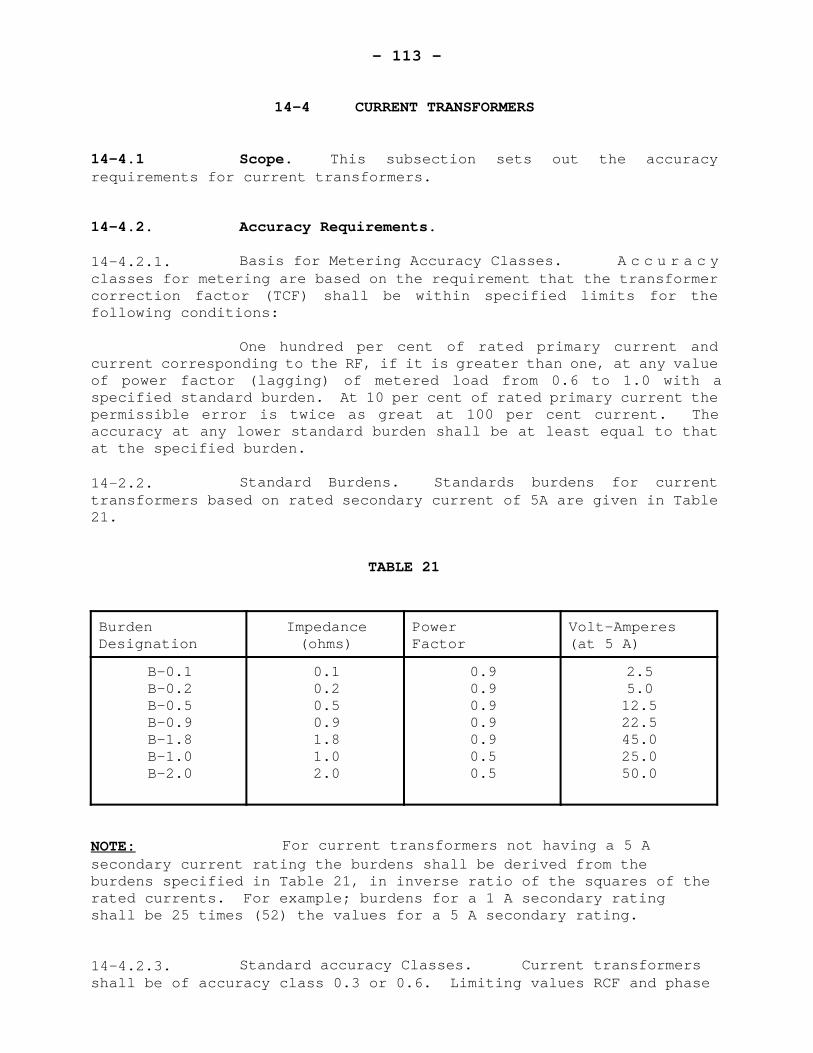
- 113 -
14-4 CURRENT TRANSFORMERS
14-4.1 Scope. This subsection sets out the accuracyrequirements for current transformers.
14-4.2. Accuracy Requirements.
14-4.2.1. Basis for Metering Accuracy Classes. A c c u r a c yclasses for metering are based on the requirement that the transformercorrection factor (TCF) shall be within specified limits for thefollowing conditions:
One hundred per cent of rated primary current andcurrent corresponding to the RF, if it is greater than one, at any valueof power factor (lagging) of metered load from 0.6 to 1.0 with aspecified standard burden. At 10 per cent of rated primary current thepermissible error is twice as great at 100 per cent current. Theaccuracy at any lower standard burden shall be at least equal to thatat the specified burden.
14-2.2. Standard Burdens. Standards burdens for currenttransformers based on rated secondary current of 5A are given in Table21.
TABLE 21
BurdenDesignation
Impedance(ohms)
PowerFactor
Volt-Amperes(at 5 A)
B-0.1B-0.2B-0.5B-0.9B-1.8B-1.0B-2.0
0.10.20.50.91.81.02.0
0.90.90.90.90.90.50.5
2.55.012.522.545.025.050.0
NOTE: For current transformers not having a 5 Asecondary current rating the burdens shall be derived from theburdens specified in Table 21, in inverse ratio of the squares of therated currents. For example; burdens for a 1 A secondary ratingshall be 25 times (52) the values for a 5 A secondary rating.
14-4.2.3. Standard accuracy Classes. Current transformersshall be of accuracy class 0.3 or 0.6. Limiting values RCF and phase

- 114 -
angle for these accuracy classes are shown in Figure 5.
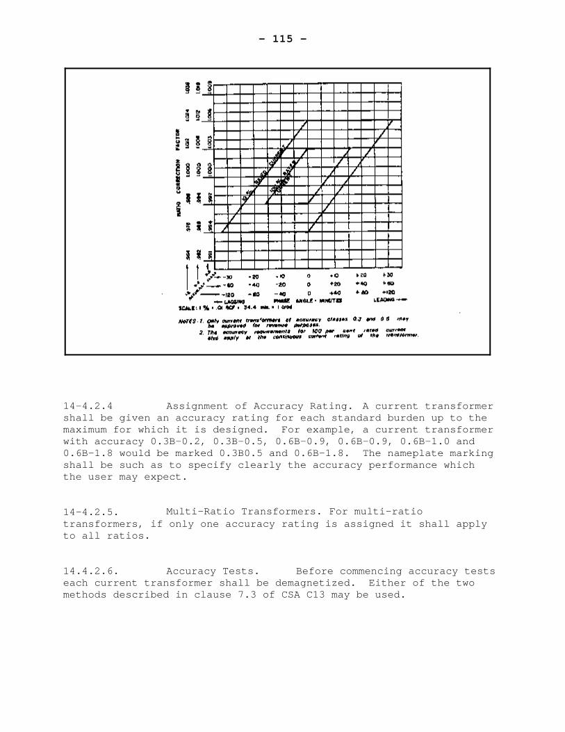
- 115 -
14-4.2.4 Assignment of Accuracy Rating. A current transformershall be given an accuracy rating for each standard burden up to themaximum for which it is designed. For example, a current transformerwith accuracy 0.3B-0.2, 0.3B-0.5, 0.6B-0.9, 0.6B-0.9, 0.6B-1.0 and0.6B-1.8 would be marked 0.3B0.5 and 0.6B-1.8. The nameplate markingshall be such as to specify clearly the accuracy performance whichthe user may expect.
14-4.2.5. Multi-Ratio Transformers. For multi-ratiotransformers, if only one accuracy rating is assigned it shall applyto all ratios.
14.4.2.6. Accuracy Tests. Before commencing accuracy testseach current transformer shall be demagnetized. Either of the twomethods described in clause 7.3 of CSA C13 may be used.
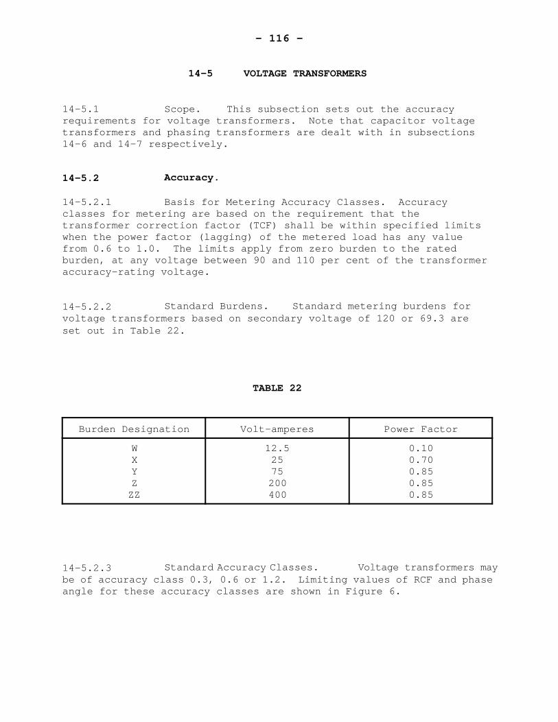
- 116 -
14-5 VOLTAGE TRANSFORMERS
14-5.1 Scope. This subsection sets out the accuracyrequirements for voltage transformers. Note that capacitor voltagetransformers and phasing transformers are dealt with in subsections14-6 and 14-7 respectively.
14-5.2 Accuracy.
14-5.2.1 Basis for Metering Accuracy Classes. Accuracyclasses for metering are based on the requirement that thetransformer correction factor (TCF) shall be within specified limitswhen the power factor (lagging) of the metered load has any valuefrom 0.6 to 1.0. The limits apply from zero burden to the ratedburden, at any voltage between 90 and 110 per cent of the transformeraccuracy-rating voltage.
14-5.2.2 Standard Burdens. Standard metering burdens forvoltage transformers based on secondary voltage of 120 or 69.3 areset out in Table 22.
TABLE 22
Burden Designation Volt-amperes Power Factor
WXYZZZ
12.52575200400
0.100.700.850.850.85
14-5.2.3 Standard Accuracy Classes. Voltage transformers maybe of accuracy class 0.3, 0.6 or 1.2. Limiting values of RCF and phaseangle for these accuracy classes are shown in Figure 6.
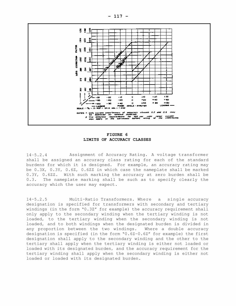
- 117 -
FIGURE 6LIMITS OF ACCURACY CLASSES
14-5.2.4 Assignment of Accuracy Rating. A voltage transformershall be assigned an accuracy class rating for each of the standardburdens for which it is designed. For example, an accuracy rating maybe 0.3X, 0.3Y, 0.6Z, 0.6ZZ in which case the nameplate shall be marked0.3Y, 0.6ZZ. With such marking the accuracy at zero burden shall be0.3. The nameplate marking shall be such as to specify clearly theaccuracy which the user may expect.
14-5.2.5 Multi-Ratio Transformers. Where a single accuracydesignation is specified for transformers with secondary and tertiarywindings (in the form “0.3Z” for example) the accuracy requirement shallonly apply to the secondary winding when the tertiary winding is notloaded, to the tertiary winding when the secondary winding is notloaded, and to both windings when the designated burden is divided inany proportion between the two windings. Where a double accuracydesignation is specified (in the form “0.6Z-0.6Z” for example) the firstdesignation shall apply to the secondary winding and the other to thetertiary shall apply when the tertiary winding is either not loaded orloaded with its designated burden, and the accuracy requirement for thetertiary winding shall apply when the secondary winding is either notloaded or loaded with its designated burden.
- 118 -
14-6 CAPACITOR VOLTAGE TRANSFORMERS
14-6.1 Scope. This subsection sets out the requirements, inaddition to those in subsection 14-3 and 14-5, which pertain tocapacitor voltage transformers.
14-6.2 Markings
14-6.2.1. Assembly. If a capacitor voltage transformer iscomposed o various components which must be assembled according to aprescribed pattern, each component shall be clearly and permanentlymarked with a serial number so that proper assembly may be readilychecked.
14-6.2.2 Nameplate. The nameplate shall include thefollowing:
(a) the words “CAPACITOR VOLTAGE TRANSFORMER”(b) the capacitance values of C1 and C2 and their
serial numbers
14-6.3 Accuracy
Capacitor voltage transformers equipped with carrieraccessories shall meet the specified accuracy rating with and withoutthe accessories in the circuit.
- 119 -
14-7 PHASING TRANSFORMERS
14-7.1 Scope
Phasing transformers shall, in general, meet therequirements set out in subsections 14-3 and 14-5 relating to voltagetransformers. For phasing transformers the basis for accuracyclassification is different. The special requirements for phasingtransformers are set out in this subsection.
14-7.2 Accuracy
14-7.2.1 Basis for Metering Accuracy Classes. Accuracy Classesare based on the requirement that the error in var or var hourmeasurement due to the phasing transformer, expressed as a percentageof volt-amperes hours is within the limit specified by the classdesignation.
14-7.2.2 Standard Accuracy Classes. Standard accuracyclasses shall be 0.3, 0.6, and 1.2. Limiting values of RCF and phasedefect for these accuracy classes are shown in Figure 7.
14-7.2.3 Accuracy Rating. Accuracy ratings shall apply forany burden from zero to the rated burden at any voltage between 90 and110 per cent of the accuracy-rating voltage. All windings shall beburdened equally and simultaneously.

- 120 -
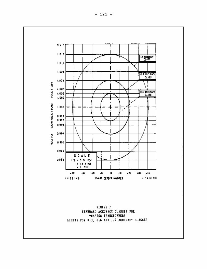
- 121 -
- 122 -
SECTION 15 - STATIC DEMAND METERS
CONTENTS
Page
15-1 SCOPE. . . . . . . . . . . . . . . . . . . . . . . . . . . . . 116
15-2 MECHANICAL REQUIREMENTS . . . . . . . . . . . . . . . . . . 116
15-3 ELECTRICAL REQUIREMENTS . . . . . . . . . . . . . . . . . . 11615-3.1 Test links . . . . . . . . . . . . . . . . . . . 11615-3.2 Demand Interval . . . . . . . . . . . . . . . . 11615-3.3 Security . . . . . . . . . . . . . . . . . . . . 116
15-4 MARKINGS . . . . . . . . . . . . . . . . . . . . . . . . . 11715-4.1 Nameplates . . . . . . . . . . . . . . . . . . . 11715-4.2 Meters Compensated for Line or
Transformer Losses . . . . . . . . . . . . 117
15-5 PERFORMANCE REQUIREMENTS . . . . . . . . . . . . . . . . . 11815-5.1 Registration at Zero Load . . . . . . . . . . . 11815-5.2 Load Performance . . . . . . . . . . . . . . . . 11815-5.3 Variation with Power Factor . . . . . . . . . . 11815-5.4 Valance . . . . . . . . . . . . . . . . . . . . 11815-5.5 Effect of Voltage Variation . . . . . . . . . . 11815-5.6 Effect of Variation of Ambient Temperature . . . 11915-5.7 Effect of an External Magnetic Field . . . . . . 11915-5.8 Effect of Momentary Overload . . . . . . . . . . 11915-5.9 Polyphase, Individual Elements . . . . . . . . . 11915-5.10 Balanced Polyphase . . . . . . . . . . . . . . . 11915-5.11 EMI Susceptibility . . . . . . . . . . . . . . . 119
- 123 -
SECTION 15 - STATIC DEMAND METERS
15-1 SCOPE
These specifications apply to solid state demandmeters.
15-2 MECHANICAL REQUIREMENTS
The requirements of subsection 3-2 shall apply.
15-3 ELECTRICAL REQUIREMENTS
15-3.1 Test Links. All self-contained S base meters shallbe fitted with test links enabling the isolation of the potentialcircuits from the current circuits.
15-3.2 Demand Interval. The demand interval shall be notless than 15 minutes. The demand interval shall be not less than 15minutes. The demand shall be averaged over the demand interval, but itmay be recalculated after each update interval.
15-3.3 Security. The requirements of clause 13-6.3 shallapply.
- 124 -
15-4 MARKINGS
15-4.1 Nameplates. In addition to the requirements ofclause 3-4.1, the nameplate shall bear the following information:
I) Rated Frequency ii) Rated voltage or voltages iii) Current range or rating iv) Response period or demand interval v) Update interval (if applicable) vi) Maximum demand rating vii) Single-phase test constant (if applicable vii) One of the following:
1-phase, 2-wire,1-phase, 3-wire,2-element2-element network2-element, 3-phase, 3-wire2½ -element wye2½ -element delta3-element wye
NOTE: Accepted symbols are Ø, EL, Y, ).
ix) All information essential for determination of thedemand from the meter indication.
x) For primary rated meters; also:(a) Current transformer rating, e.g. CT 100-5 A(b) Voltage transformer rating, e.g. VT
xi) For single phase transformer type meters the words“Transformer Type” in red.
If the meter is provided with accessories such asretransmitting contacts, etc., the nameplate shall so specify and adiagram of connections shall be provided if considered necessary by theDirector.
The markings shall be indelible, distinct, and visiblefrom outside the meter with all covers in place.
Space shall be provided for affixing an inspectionnumber.
15-4.2 Meters Compensated for Line or Transformer Losses.Meters which are internally compensated for line or transformer lossesshall have “LOSS COMPENSATED” indelibly marked in red on the nameplate.
- 125 -
15-5 PERFORMANCE REQUIREMENTS
The performance requirements of subsection 15-5 pertainto measured values. Calculated quantities derived from two or moremeasured values shall meet the requirements of subclause 13-5.1.2.
15-5.1 Registration at Zero Load. Under the referenceconditions specified in clause 3-5.1, and with zero current applied, theoutput shall not exceed 0.1% of the maximum rated demand.
15-5.2 Load Performance. Under reference conditions and atunity power factor, for any current between 10% and 100% Imax, the deviceshall register the load to within +0.5% of the true value.
15-5.3 Variation with Power Factor. U n d e r r e f e r e n c econditions, and at 0.5 leading and lagging power factors, for anycurrent between 10% and 100% Imax, the device shall register the load towithin +0.75% of the true value.
15-5.4 Balance. Under reference conditions specified inclause 3-5.1, with only one current circuit being energized in turn.The difference between any two readings shall not exceed 0.5% of thetrue value.
15-5.5 Effect of Voltage Variation. With the meter energizedunder reference conditions and with the current circuits carrying 50%of maximum load, the output demand reading shall be checked with theapplied voltage 10% above and 10% below the nameplate rating. Theauxiliary supply voltage shall be simultaneously variated in the sameway. The error of indication shall not increase by more than 0.2% atunity power factor nor by more than 0.4% at 0.5 lagging power factor and0.866 leading power factor.
- 126 -
15-5.6 Effect of Variation of Ambient Temperature. T h emaximum allowable influence due to variation in ambient temperatureshall be no more than 0.03% of true value per 0C.
This influence shall be determined by comparing theperformance under reference conditions with that at -400C and +530C orat the temperature extremes specified on the nameplate, whichever isless.
15-5.7 Effect of External Magnetic Field. The change in themetering error at 50% Imax shall not exceed +1.0% of true value when themeter is subjected to an external magnetic field. The magnetic fieldshall be equivalent to that produced by a coil one metre in diameterhaving a magnetomotive force of 400 ampereturns. The frequency of thecoil current is to be the same as that applied to the meter. The phaseof the coil current and the orientation of the coil shall be such as toproduce the maximum effect. For polyphase meters, the test voltages andcurrents shall be balanced polyphase.
15-5.8 Effect of Momentary Overload. With all potentialcircuits energized and with current circuits connected series assisting,the meter shall be subjected to a current equal to 10 times I max at unitypower factor. The variation in error shall not exceed +0.75% of thetrue value at unity power factor, and accurate to +1% of true value at0.5 lagging power factor.
15-5.10 Balanced Polyphase. With balanced polyphase currentsand voltages applied to the meter, and at any current between 10% and100% Imax, the meter shall be accurate to within +0.75% of true value atunity power factor, and accurate to +1.0% at 0.5 leading and laggingpower factors.
15-5.11 EMI Susceptibility. Meters shall be subject to the EMIsusceptibility tests set forth in clause 3-5.2.
- 127 -
SECTION 16 - INDUCTION TYPE
VOLTAGE-SQUARED HOUR METERS
CONTENTS
Page
16-1 SCOPE . . . . . . . . . . . . . . . . . . . . . . . . . . . 121
16-2 MECHANICAL REQUIREMENTS . . . . . . . . . . . . . . . . . . 121
16-3 ELECTRICAL REQUIREMENTS . . . . . . . . . . . . . . . . . . 12116-3.1 Disc Speed . . . . . . . . . . . . . . . . . . . 12116-3.2 Insulation . . . . . . . . . . . . . . . . . . . 121
16-4 MARKINGS . . . . . . . . . . . . . . . . . . . . . . . . . 12216-4.1 Nameplates . . . . . . . . . . . . . . . . . . . 122
16-5 PERFORMANCE REQUIREMENTS . . . . . . . . . . . . . . . . . 12216-5.1 Accuracy . . . . . . . . . . . . . . . . . . . . 12216-5.2 Effect of Variation of Ambient Temperature . . . 12216-5.3 Effect of External Magnetic Field . . . . . . . 12216-5.4 Polyphase Energization . . . . . . . . . . . . . 12316-5.5 Effect of Self-Heating . . . . . . . . . . . . . 12316-5.6 Effect of Tilt . . . . . . . . . . . . . . . . . 123
- 128 -
SECTION 16 - INDUCTION TYPE
VOLTAGE-SQUARED HOUR METERS
16-1 SCOPE
The requirements of this section apply to primary andsecondary rated voltage-squared hour (V2·h) meters of the inductiontype.
16-2 MECHANICAL REQUIREMENTS
Meters shall comply with the requirements of subclauses4-2.1.1 and 4-2.2.1.
16-3 ELECTRICAL REQUIREMENTS
16-3.1 Disc Speed. The speed of the disc shall not exceed100 revolutions per minute when the meter is operating at its ratedvoltage.
16-3.2 Insulation The requirements of clause 3-3.4 shallapply with the exception that the test voltage stated in subclause 3-3.4.2 shall be 2.5kV.
- 129 -
16-4 MARKINGS
16-4.1 Nameplates. In addition to the requirements ofclause 3-4.1, the nameplate shall bear the following information.
I) Rated frequency ii) Rated voltageiii) Number of elements iv) For secondary-rated meters, the single phase
test constant and the pulse constant Kp inV2.h per pulse
v) For primary rated metersa. Voltage Transformer ratiob. Pulse constant Kp in V2.h per pulse
16-5 PERFORMANCE REQUIREMENTS
16-5.1 Accuracy. Under reference conditions specified inclause 3-5.1 and over the metering range of +15% of the rated voltagethe metering error shall not exceed +1.0% of true value.
16-5.2 Effect of Variation of Ambient Temperature. T h emaximum allowable influence due to variation in ambient temperatureshall not exceed 0.06% of true value per 0C at 25% Imax.
This influence shall be determined by comparing theperformance under reference conditions with that at -400C and +530C, orat the temperature extremes specified on the nameplate, whichever isless.
16-5.3 Effect of External Magnetic Field. The change in themetering error at rated voltage shall not exceed 1.0% of true value whenthe meter is subjected to an external magnetic field. The magneticfield shall be equivalent to that produced by a coil one metre indiameter having a magnetomotive force of 400 ampere-turns. Thefrequency of the coil shall be the same as that applied to the meter.The phase of the metered voltage and the orientation of the coil shallbe such as to produce the maximum effect. For polyphase meters, thevoltages shall be balanced polyphase.
- 130 -
16-5.4 Polyphase Energization. Polyphase meters shall betested for accuracy at rated voltage with balanced polyphase voltages.The metering error shall not differ from that established pursuant toclause 16-5.1 by more than +0.3%.
16-5.5 Effect of Self-Heating. Sustained operation at ratedvoltage under single phase conditions shall not change the meteringerror by more than 0.5% from that determined within two minutes of theapplication of the metered voltage.
16-5.6 Effect of Tilt. At rated voltage and under singlephase conditions, tilting the meter up to 30 from the vertical shall notchange the metering error by more than 1.0% from that determinedaccording to clause 16-5.1.
- 131 -
SECTION 17 - STATIC VOLTAGE-SQUARED HOUR METERS
CONTENTS
Page
17-1 SCOPE . . . . . . . . . . . . . . . . . . . . . . . . . . . 125
17-2 MECHANICAL REQUIREMENTS . . . . . . . . . . . . . . . . . . 125
17-3 ELECTRICAL REQUIREMENTS . . . . . . . . . . . . . . . . . . 12517-3.1 Testing . . . . . . . . . . . . . . . . . . . . 125
17-4 MARKINGS . . . . . . . . . . . . . . . . . . . . . . . . . 12617-4.1 Nameplate . . . . . . . . . . . . . . . . . . . 126
17-5 PERFORMANCE REQUIREMENTS . . . . . . . . . . . . . . . . . 12617-5.1 Registration at Zero Voltage . . . . . . . . . . 12617-5.2 Performance Accuracy . . . . . . . . . . . . . . 12617-5.3 Effect of Variation of Ambient Temperature . . . 12617-5.4 Effect of External Magnetic Field . . . . . . . 12717-5.5 Polyphase Energization . . . . . . . . . . . . . 12717-5.6 EMI Susceptibility . . . . . . . . . . . . . . . 127
- 132 -
SECTION 17 - STATIC VOLTAGE-SQUARED HOUR METERS
17-1 SCOPE
The requirements of this section apply to primary andsecondary rated solid-state voltage-squared hour (V2·h) meters.
17-2 MECHANICAL REQUIREMENTS
The requirements of subsection 3-2 shall apply.
17-3 ELECTRICAL REQUIREMENTS
17-3.1 Testing. Each meter shall be provided with a testingmeans to facilitate calibration (in a manner analogous to counting thedisc revolutions of an induction type meter).
This testing means shall provide at least 5 pulses (orother indications) per minute when operating at the rated nameplatevoltage under single phase reference conditions specified in clause 3-5.1.
- 133 -
17-4 MARKINGS
17-4.1 Nameplates. In addition to the requirements ofclause 3-4.1, the nameplate shall bear the following information:
I) Rated frequency ii) Rated voltageiii) Number of elements iv) For secondary-rated meters, the single phase
test constant and the pulse constant Kp inV2·h per pulse
v) For primary rated metersa. Voltage transformer ratiob. Pulse constant Kp in V2·h per pulse
17-5 PERFORMANCE REQUIREMENTS
17-5.1 Registration at Zero Voltage. Under the referenceconditions set out in clause 3-5.1 and with no voltage applied, theregistration shall not increase by more than one division of the lowestreading drum, dial or digit over a four hour period. Meters with pulseinitiators shall not produce more than one output pulse over a four hourperiod.
17-5.2 Accuracy. Under reference conditions and over themetering range or +20% rated voltage, the metering error shall notexceed +0.5% of true value.
17-5.3 Effect of Variation of Ambient Temperature. T h emaximum allowable influence due to variation in ambient temperatureshall not exceed 0.05% of true value per 0C at rated voltage.
This influence shall be determined by comparing theperformance under reference conditions with that at -400C and +530C orat the temperature extremes specified on the nameplate, whichever isless.
- 134 -
17-5.4 Effect of External Magnetic Field. The change in themetering error at rated voltage shall not exceed +1.0% of true valuewhen the meter is subjected to an external magnetic field. The magneticfield shall be equivalent to that produced by a coil one metre indiameter having a magnetomotive force of 400 ampere-turns. Thefrequency of the coil is to be the same as that applied to the meter.The phase of the metered voltage and the orientation of the coil shallbe such as to produce the maximum effect. For polyphase meters, thevoltages shall be balanced polyphase.
17-5.5 Polyphase Energization. Polyphase meters shall betested for accuracy at rated voltage with balanced polyphase voltages.The error shall not differ from that established pursuant to clause 17-5.2 by more than +0.1%.
17-5.6 EMI Susceptibility. Meters shall be subject to the EMIsusceptibility tests set forth in clause 3-5.2.
- 135 -
SECTION 18 - SUB-METERING
CONTENTS
Page
18-1 SCOPE . . . . . . . . . . . . . . . . . . . . . . . . . . . 129
18-2 MECHANICAL REQUIREMENTS . . . . . . . . . . . . . . . . . . 12918-2.1 General . . . . . . . . . . . . . . . . . . . . 12918-2.2 Nameplate Location . . . . . . . . . . . . . . . 12918-2.3 Current Sensing Transformers . . . . . . . . . . 129
18-3 ELECTRICAL REQUIREMENTS . . . . . . . . . . . . . . . . . . 13018-3.1 General . . . . . . . . . . . . . . . . . . . . 13018-3.2 Metering Configuration . . . . . . . . . . . . . 130
18-4 MARKINGS . . . . . . . . . . . . . . . . . . . . . . . . . 13018-4.1 Nameplates . . . . . . . . . . . . . . . . . . . 130
18-5 PERFORMANCE . . . . . . . . . . . . . . . . . . . . . . . . 13018-5.1 Deviation between Channels . . . . . . . . . . . 130
- 136 -
SECTION 18 SUB-METERING
18-1 SCOPE
These specifications apply to metering systems ordevices used to apportion a total electricity bill among severalcustomers.
18-2 MECHANICAL REQUIREMENTS
18-2.1 General. The load of each individual customer shall bemetered by approved metering devices. The applicable requirements areset out in other sections of these specifications.
18-2.2 Nameplate Location. The nameplate shall be affixed tothe exterior of the cabinet of the system master processor.
18-2.3 Current Sensing Transformers. Systems using ringcurrent transformers for sensing the current drawn by a load shall usetransformers of such a size that will, with the transformers installedin service, allow for 5 additional turns of #16 wire to be threadedaround the core for testing purposes.
18-3 ELECTRICAL REQUIREMENTS
18-3.1 General. The data processing system shall provide thefollowing information:
I) The total energy consumed by all customersbeing apportioned.
ii) The energy consumed by each individualcustomer during the billing period.
iii) The percentage of the total bill applicableto each customer.
The above shall be stored electronically or by someother means for the minimum period set out in the Electricity and GasInspection Regulations.
- 137 -
18-3.2 Metering Configuration. In order to facilitateaccurate testing, the metering circuit shall be configured as follows:
i) So the meter and associated sensors andtransformers may be removed from the circuit fortesting, or:
ii) So a portable metering standard can be insertedinto the circuits.
18-4 MARKINGS
18-4.1 Nameplates. In addition to the requirements of otherapplicable sections, the nameplate shall include the following date:
i) The transfer constant of the meter sensor,i.e. the value of the measured quantity perunit of sensor output.
ii) The maximum permissible length of a singleconductor between the load sensor and theassociated meter, and the applicable wiresize.
iii) The load range of the sensor iv) The nominal metering voltage. v) Space to mark the number of customers being
apportioned.
18-5 PERFORMANCE REQUIREMENTS
18-5.1 Deviation between Channels. With equal loads appliedto all channels between minimum and maximum, the deviation of outputreadings between any two channels shall not be greater than ±1.0% of thetrue value.
- 138 -
SECTION 19 SIGNAL CONVERTERS
CONTENTS
Page
19-1 SCOPE . . . . . . . . . . . . . . . . . . . . . . . . . . . 132
19-2 MECHANICAL REQUIREMENTS . . . . . . . . . . . . . . . . . . 132
19-3 ELECTRICAL REQUIREMENTS . . . . . . . . . . . . . . . . . . 132
19-4 MARKING . . . . . . . . . . . . . . . . . . . . . . . . . . 13219-4.1 Nameplate . . . . . . . . . . . . . . . . . . . 132
19-5 PERFORMANCE REQUIREMENTS . . . . . . . . . . . . . . . . . 13219-5.1 Accuracy at Reference Conditions . . . . . . . 13219-5.2 Zero Drift . . . . . . . . . . . . . . . . . . . 13319-5.3 Effect of Voltage Variation . . . . . . . . . . 13319-5.4 Effect of Variation of Ambient Temperature . . . 13319-5.5 EMI Susceptibility . . . . . . . . . . . . . . . 133
- 139 -
SECTION 19 SIGNAL CONVERTERS
19-1 SCOPE
These specifications apply to devices not covered inother sections which convert an electrical signa l from one form intoanother. For example, this section includes, but is not restricted to,analog-to-digital converters, and analog-to-frequency converters.
19-2 MECHANICAL REQUIREMENTS.
The requirements of subsection 3-2 shall apply.
19-3 ELECTRICAL REQUIREMENTS
The requirements of subsection 3-3 shall apply.
19-4 MARKINGS
19-4.1 Nameplate. In addition to the requirements ofclause 3-4.1, the nameplate shall bear the following information:
I) Type of input and output. ii) Range of input(s)iii) Relationship of output to input iv) A Connection diagram, if considered
necessary by the Director.
19-5 PERFORMANCE REQUIREMENTS
19-5.1 Accuracy at Reference Conditions. F o r a n y i n p u tbetween minimum and maximum, the output shall reflect the input towithin +0.1% of reading.
- 140 -
19-5.2 Zero Drift. With the input supplied with a signalcorresponding to the zero of the quantity being metered, the error ofthe output of the device shall not exceed 0.1% of the rated maximum atany time during a four hour period.
19-5.3 Effect of Voltage Variation. With the input signalat mid range between minimum and maximum, the auxiliary voltage shallbe varied 10% above and below the value marked on the nameplate. Theerror of the output shall not exceed +0.1% of reading.
19-5.4 Effect of Variation of Ambient Temperature. T h emaximum allowable influence due to variation in ambient temperatureshall be +0.01% of full scale value per 0C.
19-5.5 EMI Susceptibility. Devices shall be subject to therequirements of clause 3-5.2.
Recommended