SOFTWARE TESTING-UNIT 2
Prepared by Dr. R. Kavitha Page 1
2.1 Test Case Design Strategies
The two basic testing strategies
1. Using the Black Box Approach to Test Case Design
2. Using the White Box Approach to Test Case Design
1. Using the Black Box Approach to Test Case Design
• Using the black box approach, a tester considers the software-under test to be an
opaque box. There is no knowledge of its inner structure (i.e., how it works).
• The tester only has knowledge of what it does.
• The size of the software-under-test using this approach can vary from a simple
module, member function, or object cluster to a subsystem or a complete Software
system.
• The description of behavior or functionality for the software-under-test may come
from a formal specification, an Input/Process/Output Diagram (IPO), or a well-
defined set of pre and post conditions.
• Another source for information is a requirements specification document that
usually describes the functionality of the software-under-test and its inputs and
expected outputs.
• The tester provides the specified inputs to the software-under-test, runs the test and
then determines if the outputs produced are equivalent to those in the specification.
• Because the black box approach only considers software behavior and
functionality, it is often called functional or specification- based testing.
• This approach is especially useful for revealing requirements and specification
defects.
SOFTWARE TESTING-UNIT 2
Prepared by Dr. R. Kavitha Page 2
Example
LOCK AND KEY: Should not know the levers in the lock, but we know the set of
inputs and expected output ( Lock and unlock)
Functionality
1. Features of a Lock:
Made up of metal
It has a Hole Provision to lock
Facility to insert key
Ability to turn clockwise and anticlockwise direction
2. Features of a Key
It is made of metal
It Fit into a particular lock’s keyhole
3. Action performed
Key inserted and turned clockwise to lock
Key inserted and turned anticlockwise unlock
4. States
Locked and unlocked
5. Inputs
Key turned clockwise or anticlockwise
6. Expected outcome
Locking and unlocking
Note: • Black box test strategy- only inputs and outputs are considered as a basis
for designing test cases • Selection of set of inputs from the set of all possible valid and invalid inputs
is an important, because exhaustive testing is not possible.
Different types of black box testing:
Requirement based testing, Random Testing Requirements based testing, Boundary
Value Analysis , Equivalence Class Partitioning, State-based testing , Cause-effect graphing,
Compatibility testing, user documentation testing, domain testing
2.2. Requirement based Testing
Requirement based testing is validating the requirements given in the SRS of the software
system and also validating explicitly stated and implied requirements.
SOFTWARE TESTING-UNIT 2
Prepared by Dr. R. Kavitha Page 3
Precondition for requirements testing is Review of the requirements specification.
Review ensures the requirements are consistent, correct, complete and testable.
During review process – Implied requirements converted into explicit requirements.
Example :
Sample requirements specification for lock and key system
The following table shows the requirements for lock and key system and its priority also fixed.
Requirement
Identifier
Description Priority
BR-01 Inserting the key numbered KEY09 and turning it CW should
facilitate locking
High
BR-02 Inserting the key numbered KEY09 and turning it ACW should
facilitate unlocking
High
BR-03 Only key no. KEY09 should be used for lock and unlock High
BR-04 No other object can be used for lock Medium
BR-05 No other object can be used for unlock Medium
BR-06 Lock should not open even with a heavy object Medium
BR-07 Should be made of metal and weight should be 150 grams Low
BR-08 Lock and unlock directions should be changeable for usability of
left-handers
Low
For the above requirements, test cases are framed with precondition and it is also listed in the
next table.
Req
Id
Description Priority Test
conditions
Test
case Ids
Phase of
Testing
BR-
01
Inserting the key numbered
KEY09 and turning it CW
should facilitate locking
High Use Key
KEY09
TC1
Unit,
Component
BR-
02
Inserting the key numbered
KEY09 and turning it ACW
should facilitate unlocking
High Use Key
KEY09
TC2
Unit,
Component
BR- Only key no. KEY09 should be High Use Key TC3 Component
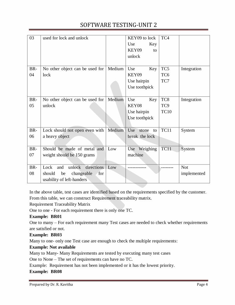
SOFTWARE TESTING-UNIT 2
Prepared by Dr. R. Kavitha Page 4
03 used for lock and unlock KEY09 to lock
Use Key
KEY09 to
unlock
TC4
BR-
04
No other object can be used for
lock
Medium Use Key
KEY09
Use hairpin
Use toothpick
TC5
TC6
TC7
Integration
BR-
05
No other object can be used for
unlock
Medium Use Key
KEY08
Use hairpin
Use toothpick
TC8
TC9
TC10
Integration
BR-
06
Lock should not open even with
a heavy object
Medium Use stone to
break the lock
TC11
System
BR-
07
Should be made of metal and
weight should be 150 grams
Low Use Weighing
machine
TC11
System
BR-
08
Lock and unlock directions
should be changeable for
usability of left-handers
Low ------------ -------- Not
implemented
In the above table, test cases are identified based on the requirements specified by the customer.
From this table, we can construct Requirement traceability matrix.
Requirement Traceability Matrix
One to one - For each requirement there is only one TC.
Example: BR01
One to many – For each requirement many Test cases are needed to check whether requirements
are satisfied or not.
Example: BR03
Many to one- only one Test case are enough to check the multiple requirements:
Example: Not available
Many to Many- Many Requirements are tested by executing many test cases
One to None – The set of requirements can have no TC.
Example: Requirement has not been implemented or it has the lowest priority.
Example: BR08
SOFTWARE TESTING-UNIT 2
Prepared by Dr. R. Kavitha Page 5
Advantages of RTM
RTM provides a tool to track the testing status of each requirement without missing any
requirements
Identifies defects in the high priority area by prioritization
Time limit – Omit low priority TCs.
After execution of Test cases, the test results can be used to collect metrics such as,
Total No. Of TCs passed
Total No. Of TCs failed
Total number of defects- in requirements
Number of requirements completed
Number of requirements pending
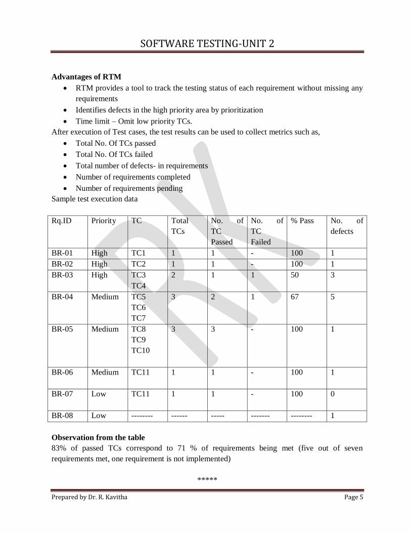
Sample test execution data
Rq.ID Priority TC Total
TCs
No. of
TC
Passed
No. of
TC
Failed
% Pass
No. of
defects
BR-01 High TC1 1 1 - 100 1
BR-02 High TC2 1 1 - 100 1
BR-03 High TC3
TC4
2 1 1 50 3
BR-04 Medium TC5
TC6
TC7
3 2 1 67 5
BR-05 Medium TC8
TC9
TC10
3 3 - 100 1
BR-06 Medium TC11
1 1 - 100 1
BR-07 Low TC11
1 1 - 100 0
BR-08 Low -------- ------ ----- ------- -------- 1
Observation from the table
83% of passed TCs correspond to 71 % of requirements being met (five out of seven
requirements met, one requirement is not implemented)
*****
SOFTWARE TESTING-UNIT 2
Prepared by Dr. R. Kavitha Page 6
2.3. Boundary Value Analysis
“Boundary value analysis is useful to generate test cases when the input data is made up
of clearly identifiable boundaries or ranges”.
Mostly in s/w defects occur due to boundaries and conditions.
Reason
Confusion to use the <= operator or < operator.
Confusion caused by the availability of multiple ways to implement loops and condition
checking.( for, while repeat loop – each of these having different terminating
conditions).
Sometimes requirement may not be clearly understood especially around the boundaries.
Example:
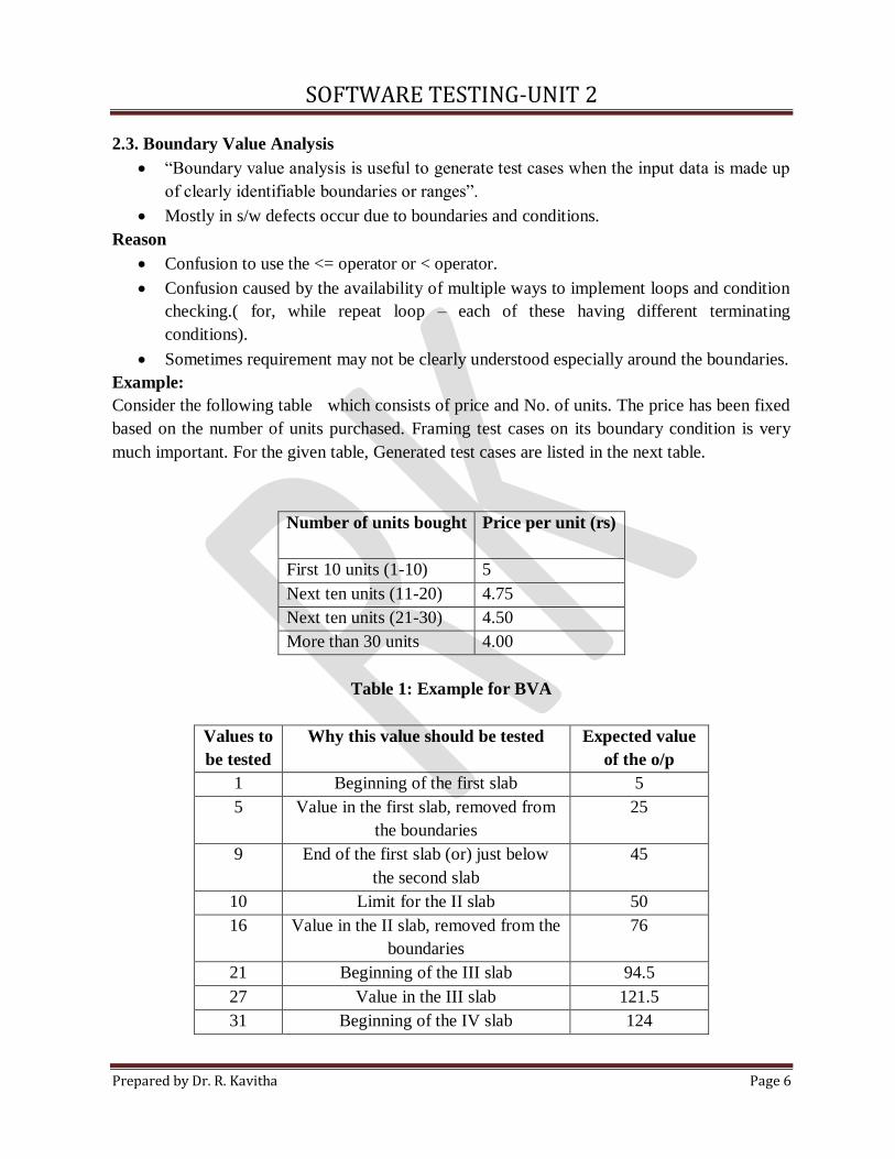
Consider the following table which consists of price and No. of units. The price has been fixed
based on the number of units purchased. Framing test cases on its boundary condition is very
much important. For the given table, Generated test cases are listed in the next table.
Number of units bought
Price per unit (rs)
First 10 units (1-10) 5
Next ten units (11-20) 4.75
Next ten units (21-30) 4.50
More than 30 units 4.00
Table 1: Example for BVA
Values to
be tested
Why this value should be tested Expected value
of the o/p
1 Beginning of the first slab 5
5 Value in the first slab, removed from
the boundaries
25
9 End of the first slab (or) just below
the second slab
45
10 Limit for the II slab 50
16 Value in the II slab, removed from the
boundaries
76
21 Beginning of the III slab 94.5
27 Value in the III slab 121.5
31 Beginning of the IV slab 124
SOFTWARE TESTING-UNIT 2
Prepared by Dr. R. Kavitha Page 7
Table: Sample test cases
*****
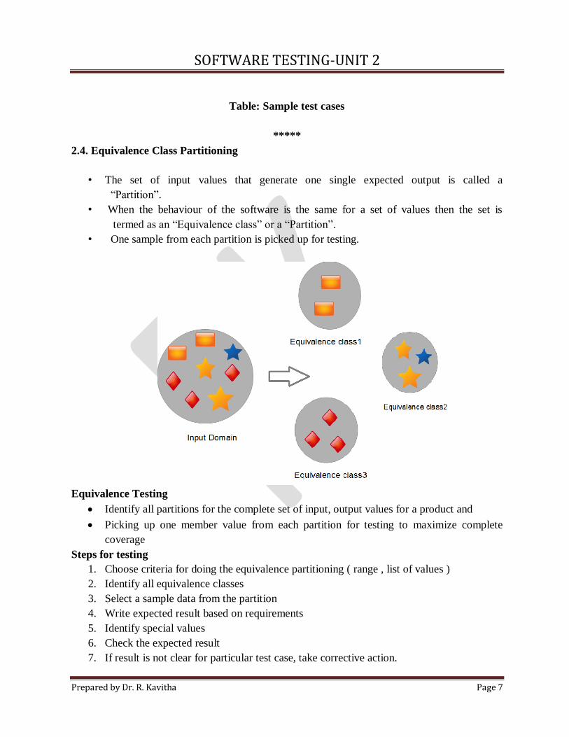
2.4. Equivalence Class Partitioning
• The set of input values that generate one single expected output is called a
“Partition”.
• When the behaviour of the software is the same for a set of values then the set is
termed as an “Equivalence class” or a “Partition”.
• One sample from each partition is picked up for testing.
Equivalence Testing
Identify all partitions for the complete set of input, output values for a product and
Picking up one member value from each partition for testing to maximize complete
coverage
Steps for testing
1. Choose criteria for doing the equivalence partitioning ( range , list of values )
2. Identify all equivalence classes
3. Select a sample data from the partition
4. Write expected result based on requirements
5. Identify special values
6. Check the expected result
7. If result is not clear for particular test case, take corrective action.
SOFTWARE TESTING-UNIT 2
Prepared by Dr. R. Kavitha Page 8
Advantages
• Good coverage with a small number of test cases.
• Redundancy of tests is minimized.
Example
• A life insurance company has base premium of Rs.100 for all ages. Additional monthly
premium has to be paid based on the age group. Conditions given below
Age Group
Additional Premium
Under 35 Rs. 200
35-59 Rs. 400
60 + Rs.1000
Based on the partition - Inputs are,
• Below 35 years of age ( valid input)
• Below 35 and 59 years of age ( valid input)
• Above 60 years of age (valid input)
• Negative age ( invalid input)
• Age as 0 (invalid input)
• Age as any three-digit number (valid input)
The valid and invalid inputs are listed in the following table.
TC
No.
Equivalence
partitions
Type of
input
Test
data
Expected results
1 Age below 35 Valid 26,12 MP=100+200
2 35-59 Valid 37 100+400
3 Age above 60 Valid 67,90 100+1000
4 Negative age Invalid -23 Warning message “invalid
input”
5 Age as 0 Invalid 0 Warning message “invalid
input”
Equivalence partitioning is useful to minimize the number of test cases when the input data can
be divided into distinct sets, where the behaviour or outcome of the product within each
member of the set is the same.
*****
2.5. State-based testing
SOFTWARE TESTING-UNIT 2
Prepared by Dr. R. Kavitha Page 9
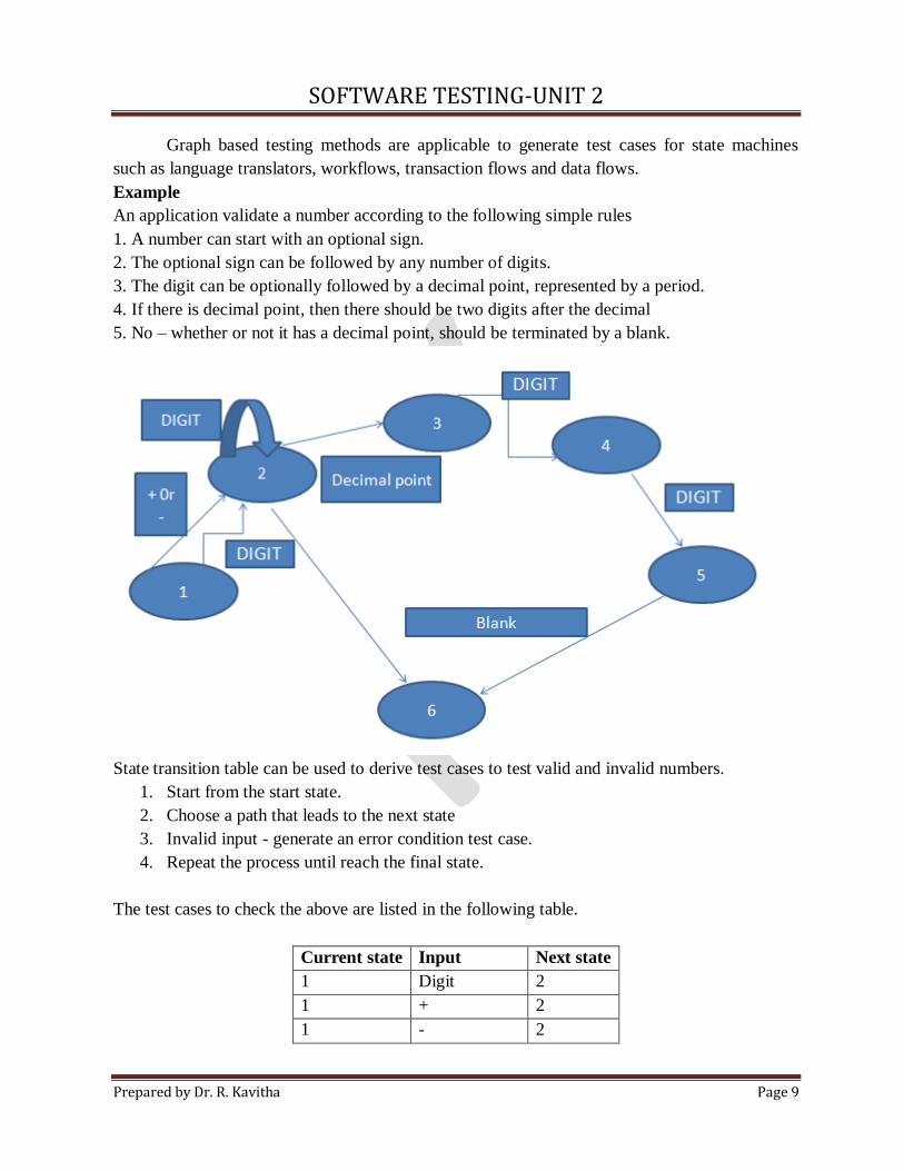
Graph based testing methods are applicable to generate test cases for state machines
such as language translators, workflows, transaction flows and data flows.
Example
An application validate a number according to the following simple rules
1. A number can start with an optional sign.
2. The optional sign can be followed by any number of digits.
3. The digit can be optionally followed by a decimal point, represented by a period.
4. If there is decimal point, then there should be two digits after the decimal
5. No – whether or not it has a decimal point, should be terminated by a blank.
State transition table can be used to derive test cases to test valid and invalid numbers.
1. Start from the start state.
2. Choose a path that leads to the next state
3. Invalid input - generate an error condition test case.
4. Repeat the process until reach the final state.
The test cases to check the above are listed in the following table.
Current state Input Next state
1 Digit 2
1 + 2
1 - 2
SOFTWARE TESTING-UNIT 2
Prepared by Dr. R. Kavitha Page 10
2 Digit 2
2 Blank 6
2 Decimal point 3
3 Digit 4
4 Digit 5
5 Blank 6
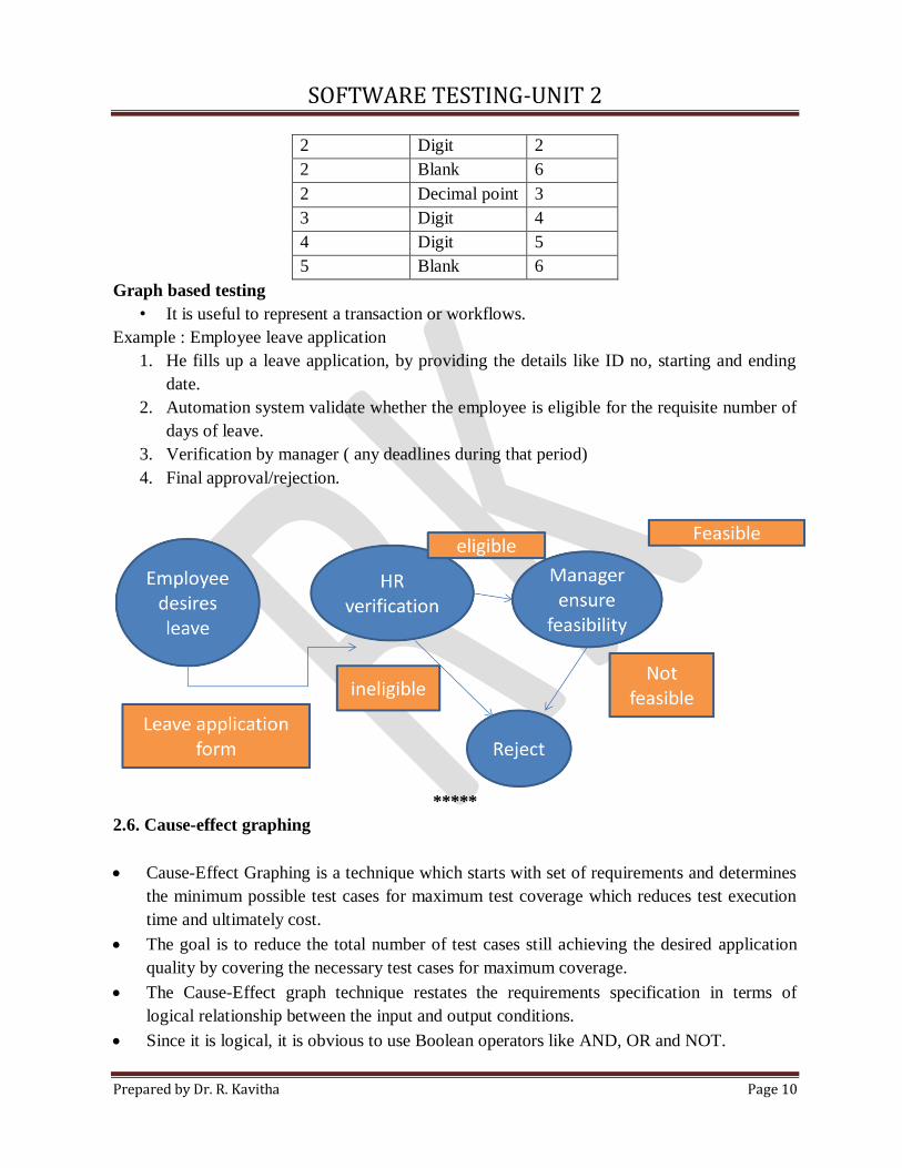
Graph based testing
• It is useful to represent a transaction or workflows.
Example : Employee leave application
1. He fills up a leave application, by providing the details like ID no, starting and ending
date.
2. Automation system validate whether the employee is eligible for the requisite number of
days of leave.
3. Verification by manager ( any deadlines during that period)
4. Final approval/rejection.
*****
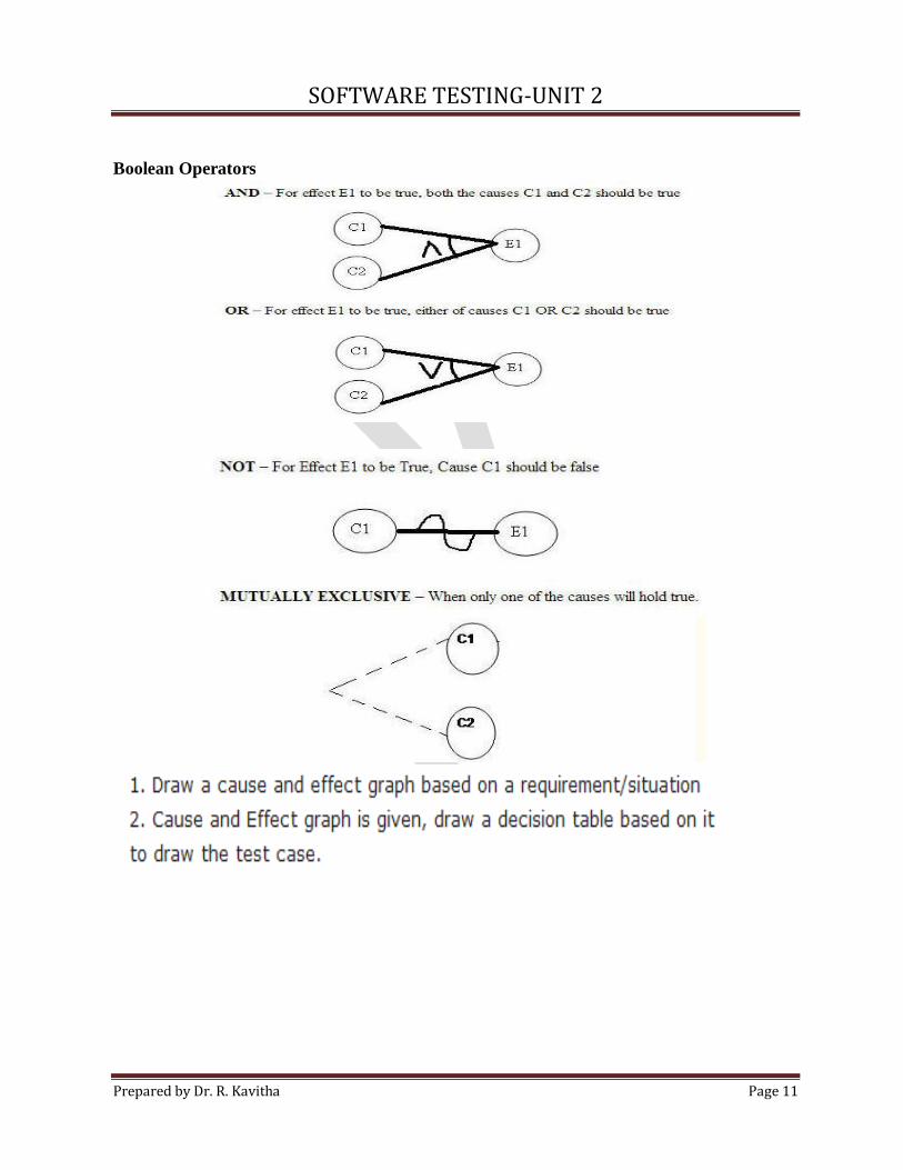
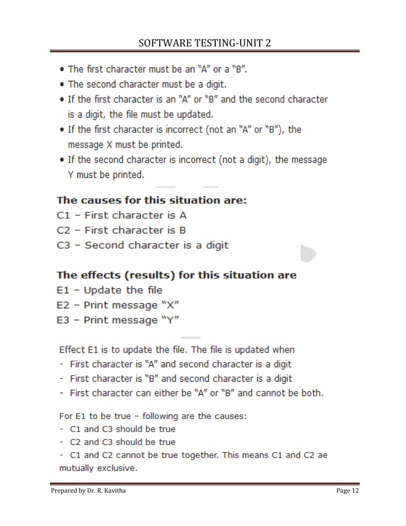
2.6. Cause-effect graphing
Cause-Effect Graphing is a technique which starts with set of requirements and determines
the minimum possible test cases for maximum test coverage which reduces test execution
time and ultimately cost.
The goal is to reduce the total number of test cases still achieving the desired application
quality by covering the necessary test cases for maximum coverage.
The Cause-Effect graph technique restates the requirements specification in terms of
logical relationship between the input and output conditions.
Since it is logical, it is obvious to use Boolean operators like AND, OR and NOT.
SOFTWARE TESTING-UNIT 2
Prepared by Dr. R. Kavitha Page 11
Boolean Operators
SOFTWARE TESTING-UNIT 2
Prepared by Dr. R. Kavitha Page 12
SOFTWARE TESTING-UNIT 2
Prepared by Dr. R. Kavitha Page 13
(C1 ᴜ C2) ∩ C3
SOFTWARE TESTING-UNIT 2
Prepared by Dr. R. Kavitha Page 14
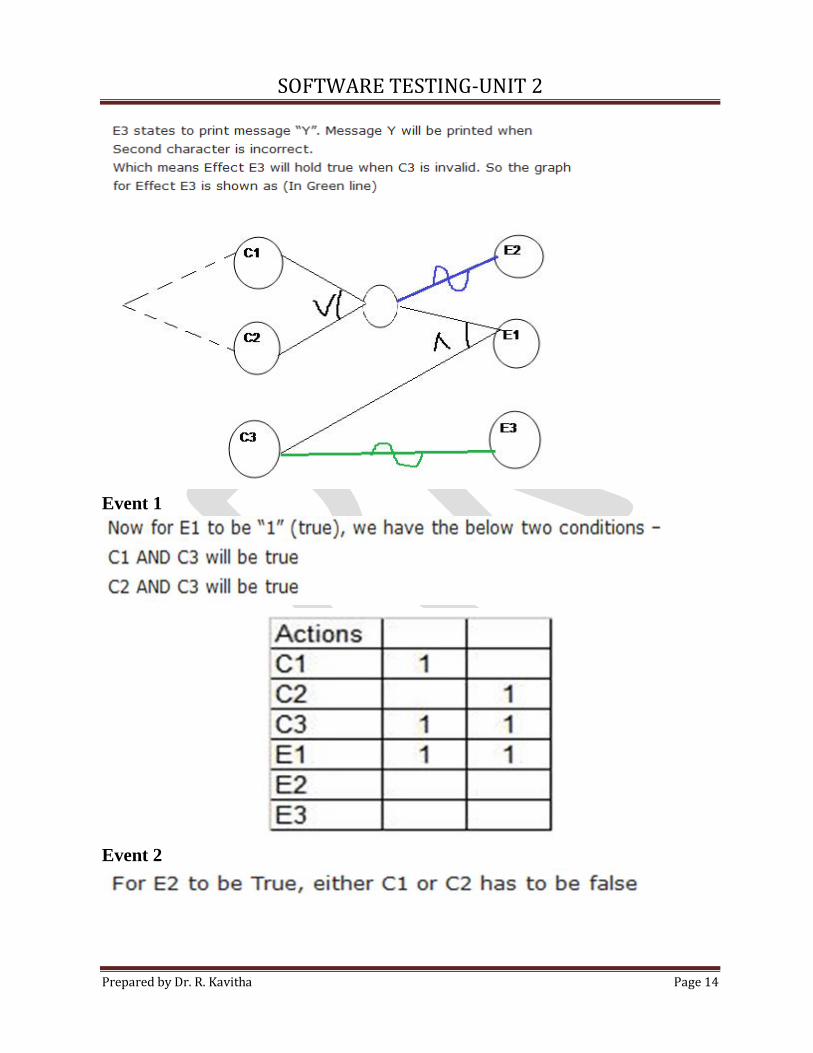
Event 1
Event 2
SOFTWARE TESTING-UNIT 2
Prepared by Dr. R. Kavitha Page 15
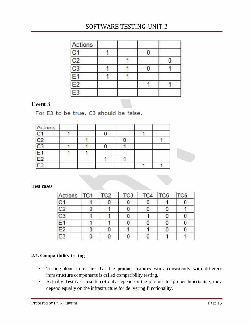
Event 3
Test cases
2.7. Compatibility testing
• Testing done to ensure that the product features work consistently with different
infrastructure components is called compatibility testing.
• Actually Test case results not only depend on the product for proper functioning, they
depend equally on the infrastructure for delivering functionality.
SOFTWARE TESTING-UNIT 2
Prepared by Dr. R. Kavitha Page 16
• When infrastructure parameters are changed, the product is expected to still behave
correctly and produce the desired or expected result.
• The infrastructure parameter may be H/W, S/W or any other component.
The parameters that generally affect the compatibility of the product are
1. Processor (P-III, P-IV, XEON ) and the No. Of processors.
2. Architecture and characteristics of the m/c ( 32 bit, 64 bit).
3. Recourse availability of the product (RAM, disk space, network card ).
4. Operating system ( windows, linux)
5. Middle tier infrastructure components ( web server, application server, network server)
6. Backend components such as database server (oracle, sybase).
7. Services that require special h/w and s/w solutions.
8. Various technological components
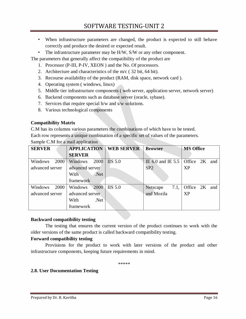
Compatibility Matrix
C.M has its columns various parameters the combinations of which have to be tested.
Each row represents a unique combination of a specific set of values of the parameters.
Sample C.M for a mail application
SERVER APPLICATION
SERVER
WEB SERVER Browser MS Office
Windows 2000
advanced server
Windows 2000
advanced server
With .Net
framework
IIS 5.0 IE 6.0 and IE 5.5
SP2
Office 2K and
XP
Windows 2000
advanced server
Windows 2000
advanced server
With .Net
framework
IIS 5.0 Netscape 7.1,
and Mozila
Office 2K and
XP
Backward compatibility testing
The testing that ensures the current version of the product continues to work with the
older versions of the same product is called backward compatibility testing.
Forward compatibility testing
Provisions for the product to work with later versions of the product and other
infrastructure components, keeping future requirements in mind.
*****
2.8. User Documentation Testing
SOFTWARE TESTING-UNIT 2
Prepared by Dr. R. Kavitha Page 17
• User documentation covers all the manuals, user guides, installation guides, setup guides,
read me file, software release notes and online help that are provided along with the
software to help the end user to understand the software system.
• U.D is done to ensure the Documentation matches the product.
Why user documentation testing?
• To check if what is stated in the document is available in the product.
• To check if what is there in the product is explained correctly in the document.
• When Product is upgraded, the corresponding product documentation should also get
updated as necessary to reflect any changes that may affect a user.
• User documentation testing focuses on ensuring what the document exactly matches the
product behaviour, by sitting in front of the system and verifying screen by screen,
transaction by transaction and report by report.
• U.D- Also check spelling and grammar.
• A badly written installation document can put off a user and bias him against the product,
even the product offers high functionality.
• It highlights the problems during reviews.
• Customer Satisfaction - Customer should get correct result after following the instructions.
Otherwise they need supporting staff for that.
• If new programmers and testers joined in the group, U.D will be useful to know the
functionality.
• Customer needs less training- U.D is user friendly.
*****
2.9. Domain Testing
• White box testing – Checking code
• Black Box testing – Checking functionality without coding knowledge. ( Checking will
be done by looking the specifications )
• Domain testing – Do not look the specification- Purely based on domain knowledge.
• It requires critical understanding of day-to-day business activities.
• Depth in business domain is a prerequisite for this testing.
• Give training for testing by taking people from the domain area ( banking, insurance) –
it reduces time and increases the testing effectiveness.
• DT- Need not to test several steps in design logic
• It‘s BBT- Check the denomination also.
• Generally DT is done after the BBT.
• DT ensures the software is written with the intelligence needed for domain.
• It examines the realistic business scenarios.
•
SOFTWARE TESTING-UNIT 2
Prepared by Dr. R. Kavitha Page 18
Example Banking : atm
• Go to the ATM
• PUT ATM card inside.
• Enter correct pin
• Choose cash withdrawal.
• Enter the amount
• Take the cash
• Exit and retrieve the card
Test Cases For One Rupee Coin Telephone Box
TC1: Pick up the Handset
Expected: Should display the message “Insert one rupee coin"
TC2: Insert the coin
Expected: Should display the message “Dial the Number“
TC3: When you get a busy tone, hang-up the receiver
Expected: The inserted one rupee coin comes out of the exit door.
TC4: Finish off the conversation and hang-up the receiver
Expected: The inserted coin should not come out.
TC5: During the conversation, in case of a local call, (assume the duration is of 60
sec), when 45s are completed
Expected: It should prompt you to insert another coin to continue by giving beeps.
TC6: In the above scenario, if another coin is inserted
Expected: 60 sec will be added to the counter.
TC7: In the TC5 scenario, if you don't insert one more coin.
Expected: The call gets ended.
TC8: Pick up the receiver. Insert appropriate one rupee coin; Dial the number after hearing
the ring tone. Assume it got connected and you are getting the ring tone. Immediately you
end up the call.
Expected: The inserted one rupee coin comes out of the exit door.
*****
SOFTWARE TESTING-UNIT 2
Prepared by Dr. R. Kavitha Page 19
2.10. Using white box testing /Test adequacy criteria
• WBT is checking if all the logical and data elements in the software unit are functioning
properly. But, BBT is used for testing both small and large s/w components.
• But WBT is used for testing the small s/w component. Since the level of detail required
for test design is very high, and the granularity of the items consider for testing is very
small.
• WBT is to ensure that the internal components of a program are working properly.
• Its focus mainly on structural components like statements and branches.
• Testers need a framework – to decide the structural element, to select appropriate test
cases. Framework exists in the form of test adequacy criteria.
• Test adequacy criterion is a stopping rule – since rules can be used to determine whether
the sufficient testing has been carried out or not.
Application of TAC includes,
• Helps to select properties of a program.
• Helps to select test case set for a program based on the property.
• Indicate the testers whether or not testing can be stopped for the program
TYPES - TAC
• Program based adequacy criteria – If TAC focuses on the structural criterion is called
PBTAC.
• Specification based adequacy criteria – If TAC focuses on program specification is
called SBTAC.
Example: statement coverage, functional coverage and branch coverage
*****
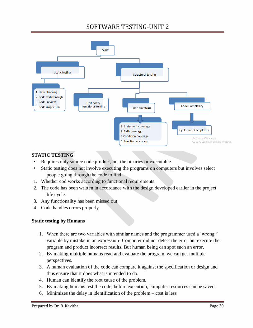
2.11. Types of White Box Testing / Static Testing
SOFTWARE TESTING-UNIT 2
Prepared by Dr. R. Kavitha Page 20
STATIC TESTING
• Requires only source code product, not the binaries or executable
• Static testing does not involve executing the programs on computers but involves select
people going through the code to find
1. Whether cod works according to functional requirements.
2. The code has been written in accordance with the design developed earlier in the project
life cycle.
3. Any functionality has been missed out
4. Code handles errors properly.
Static testing by Humans
1. When there are two variables with similar names and the programmer used a ‘wrong “
variable by mistake in an expression- Computer did not detect the error but execute the
program and product incorrect results. But human being can spot such an error.
2. By making multiple humans read and evaluate the program, we can get multiple
perspectives.
3. A human evaluation of the code can compare it against the specification or design and
thus ensure that it does what is intended to do.
4. Human can identify the root cause of the problem.
5. By making humans test the code, before execution, computer resources can be saved.
6. Minimizes the delay in identification of the problem – cost is less
SOFTWARE TESTING-UNIT 2
Prepared by Dr. R. Kavitha Page 21
7. Finding defects at an earlier stage of testing- Reduce the pressure on programmer – less
effort in coding
Static testing- Testing by human before the code is compiled and executed- so it is process
oriented process or prevention oriented or quality oriented.
Types
1. Desk checking
2. Code Walkthrough
3. Code review
4. Code inspection
1. Desk checking
• Done manually by author of the code
• Verification of the code is done for its correctness
• Verification by comparing the code with specification
• Process over before the compilation and execution of the code
Advantages
1. Programmer understand the code easily (own code)
Disadvantages
1. Finding fault in own code is not effective method.
2. Normally they start to write new code instead of testing.
3. It is a person dependent and informal
2. Code Walkthrough
• Walkthrough are less formal than inspection
• Group oriented method
• Set of people look at the program code, and Raise the questions for the author
• Author should answer the questions.
3. Code Review
The code is checked on various factors.
Data item declaration related
• Are the name of the variable meaninfgul?
• Different names – confusing use of lower case and upper case letters.
• Are variables initialized?
• Are there similar sounding names ( singular and plural names )
• All the common structures, constants and flags to be used, defined in a header file rather
than in each file separately?
SOFTWARE TESTING-UNIT 2
Prepared by Dr. R. Kavitha Page 22
• Values of right data types being assigned to the variables?
• Is the access of data from any standard files, repositories or database s done through
publicly supported interfaces?
• Pointers are properly initialized?
• Usage of Similar operators checked? ( = and == & and&& )
Control Flow Related
• Are all the conditional paths reachable?
• Are all the individual conditions in a complex condition separately evaluated?
• I f there is a nested IF statement, are the THEN and ELSE parts appropriately
delimited?
4. Code Inspection
It detects all faults, violations and other side effects. It is started after desk checking and
walkthrough
Four roles in Inspections
1. Author of the code
2. Moderator – Formally run the inspection according to the process
3. Inspectors – Provide review comments on the code
4. Scribe – takes detailed notes during inspection meeting and circulates them to the
inspection team after meeting
STATIC ANALYSIS TOOLS
Static analysis tools are Inspection, review and Manual works
Static analysis tool- Reduce the manual work and perform analysis on the code to find errors.
Reason for using SA tools:
1. Whether there are unreachable codes ( GOTO statement – sometimes creates this
situation )
2. Variables declared but not used
3. Mismatch in definition and assignment of values to variables
4. Calculation of cyclomatic complexity
5. Static analysis tool are considered as extension of compilers, Since they use same
concepts and implementation to locate errors
6. Good compiler is also a static analysis tool. Most compilers provide different level of
code checking
Ex: POSIX – Check consistency in coding ( naming conventions, allowed data types,
permissible programming constructs )
*****
SOFTWARE TESTING-UNIT 2
Prepared by Dr. R. Kavitha Page 23
2.12. Structural Testing
Structural testing is based on Code , Code structure and Internal design.
Structural testing runs by computer on the built product.
Types
1. Unit/Code functional
Developer performs testing, giving various i/p values and check the actual test result
with expected result. (Initial level )
Repeating tests for multiple values – Increase the confidence level.
Complex logic or condition – developer built a “debug version “of the product by
putting intermediate print statement and then performing the test.
After fixing of defects the intermediate print statements are removed.
Run the product under a debugger or an IDE ( Integrated Development Environment )
(single stepping of instructions )
2. Code coverage testing
Code coverage testing involves designing and executing test cases and finding out the
percentage of code that is covered by testing.
Instrumentation of code: percentage of code covered by a test .
Specialized tools are available to achieve instrumentation.
Tools monitor the codes and keep an audit of what portions of code are covered ( also
maintain code that are covered frequently )
Types
1. Statement coverage
2. Path coverage
3. Condition coverage
4. Function coverage
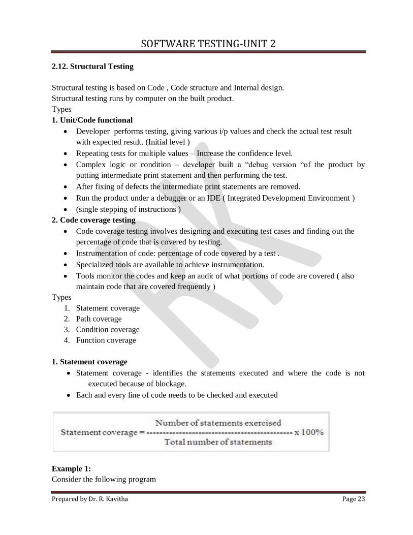
1. Statement coverage
Statement coverage - identifies the statements executed and where the code is not
executed because of blockage.
Each and every line of code needs to be checked and executed
Example 1:
Consider the following program
SOFTWARE TESTING-UNIT 2
Prepared by Dr. R. Kavitha Page 24
Read X
Read y
If X > Y then Z=0
To achieve 100% statement coverage of this code segment, just one test case is required, one
which ensures that variable X contains a value that is greater than the value of variable Y
Value of variables are X = 12 and Y=10.
Example 2:
Consider the program
1. Read X
2. Read Y
3. Z=X+2*Y
4. IF Z>50 then
5. Print large Z
6. Endif
Test Cases:
1. X = 2 , Y = 3
2. X = 0, Y = 25
3. X = 47 , Y = 1
For the first test case the value of Z = 8, it covers line 1, 2, 3, 4 and 6.
For the second test case value of Z=50, it covers line 1, 2, 3, 4 and 6.
For the third test case value of Z= 49, it also covers line 1, 2, 3, 4 and 6.
The statement coverage is 5/6 = 83%
Suppose the test case consist of X = 20 and Y = 25, then value of Z = 70, and it will exercise all
the six statements. Now the statement coverage is 100%.
2. Path Coverage
In this the test case is executed in such a way that every path is executed at least once.
Example:
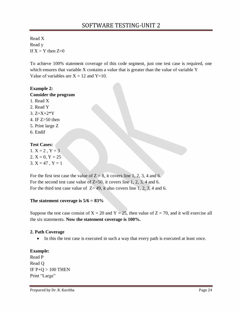
Read P
Read Q
IF P+Q > 100 THEN
Print “Large”
SOFTWARE TESTING-UNIT 2
Prepared by Dr. R. Kavitha Page 25
ENDIF
If P > 50 THEN
Print “P Large”
ENDIF
Consider the flowchart for the above program.
Path Coverage ensures covering of all the paths from start to end.
All possible paths are-
1A-2B-E-4F
1A-2B-E-4G-5H
1A-2C-3D-E-4G-5H
1A-2C-3D-E-4F
So path coverage is 4. All the paths should be checked while testing the code.
SOFTWARE TESTING-UNIT 2
Prepared by Dr. R. Kavitha Page 26
3. Condition / Branch Coverage
Total decisions exercised
Condition coverage =
Total number of decisions in program
Sometime all the conditions are not evaluated, even though the right path is chosen. Consider
the example if path is selected and it is found to be true. So the second part will not be
evaluated.
So path testing may not be sufficient, it is necessary to have test cases that exercise all the
conditions.
4. Function Coverage
Testing, to identify how many program functions are covered by test cases.
The requirements of a product are mapped into functions during the design phase and
each of the function form a logical unit.
Example: Database software
Inserting a row into the database- Function
Example: Payroll application
Calculate tax - Function
Advantages
1. It is easier to identify the function in a program – it is easier to write test cases.
2. Function has a more logical mapping to requirements – Test coverage using traceability
matrix.
3. Prioritizing the functions based on the importance of requirements.
*****
2.13. White Box testing- Coverage and control flow graph – Covering code logic
Testing the Internal logic structure of the software under test.
The tester’s goal is to determine if all the logical and data elements in the software unit
are functioning properly. This is called the white box, or glass box, approach to test
case design.
The knowledge needed for the white box test design approach often becomes available
to the tester in the later phases of the software life cycle, specifically during the detailed
design phase of development.
This is in contrast to the earlier availability of the knowledge necessary for black box
test design.
Coverage and control flow graph
Coverage analysis is typically associated with the use of control and data flow models to
represent program structural elements and data.
SOFTWARE TESTING-UNIT 2
Prepared by Dr. R. Kavitha Page 27
The logic elements most commonly considered for coverage are based on the flow of
control in a unit of code.
For example,
(i) Program statements;
(ii) Decisions/branches (these influence the program flow of control)
(iii) Conditions (expressions that evaluate to true/false, and do not contain any other
true/false-valued expressions.
(iv) Combinations of decisions and conditions;
(v) Paths (node sequences in flow graphs)
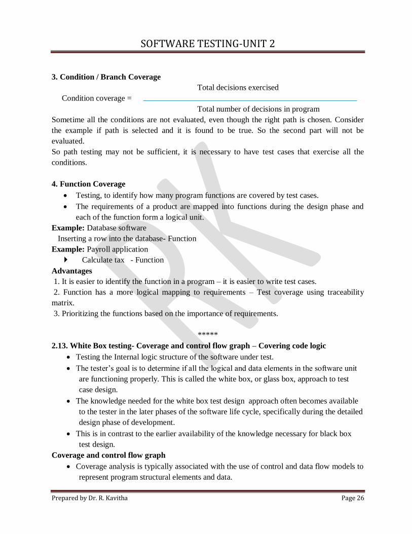
• These logical elements are rooted in the concept of a program prime.
• A program prime is an atomic programming unit. All structured programs can be
built from three basic primes-sequential (e.g., assignment statements), decision
(e.g., if/then/else statements), and iterative (e.g., while, for loops).
• Graphical representations for these three primes are shown in figure.
Figure : Representation of program primes
Using the concept of a prime and the ability to use combinations of primes to develop
structured code, a (control) flow diagram for the software unit under test can be
developed.
The flow graph can be used by the tester to evaluate the code with respect to its
testability, as well as to develop white box test cases.
Figure: Code sample with branch and loop
SOFTWARE TESTING-UNIT 2
Prepared by Dr. R. Kavitha Page 28
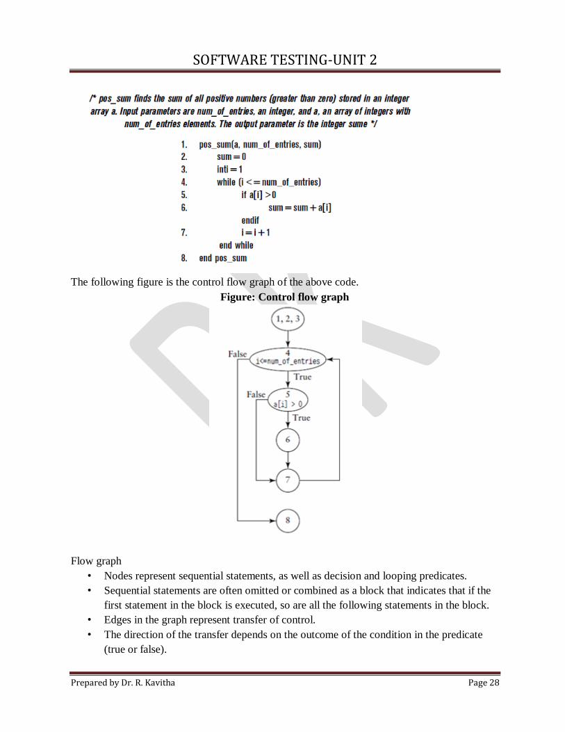
The following figure is the control flow graph of the above code.
Figure: Control flow graph
Flow graph
• Nodes represent sequential statements, as well as decision and looping predicates.
• Sequential statements are often omitted or combined as a block that indicates that if the
first statement in the block is executed, so are all the following statements in the block.
• Edges in the graph represent transfer of control.
• The direction of the transfer depends on the outcome of the condition in the predicate
(true or false).
SOFTWARE TESTING-UNIT 2
Prepared by Dr. R. Kavitha Page 29
• Commercial tools are available that will generate control flow graphs from code and in
some cases from pseudo code.
• The tester can use tool support for developing control flow graphs especially for
complex pieces of code.
Covering Code Logic
Testers are using tools and concepts to decide on the target logic elements (properties or
features of the code) and the degree of coverage.
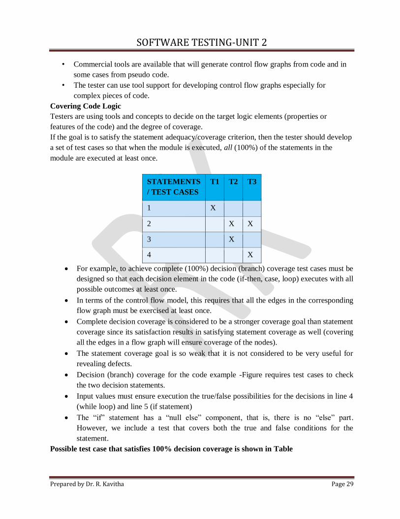
If the goal is to satisfy the statement adequacy/coverage criterion, then the tester should develop
a set of test cases so that when the module is executed, all (100%) of the statements in the
module are executed at least once.
STATEMENTS
/ TEST CASES
T1 T2 T3
1 X
2 X X
3 X
4 X
For example, to achieve complete (100%) decision (branch) coverage test cases must be
designed so that each decision element in the code (if-then, case, loop) executes with all
possible outcomes at least once.
In terms of the control flow model, this requires that all the edges in the corresponding
flow graph must be exercised at least once.
Complete decision coverage is considered to be a stronger coverage goal than statement
coverage since its satisfaction results in satisfying statement coverage as well (covering
all the edges in a flow graph will ensure coverage of the nodes).
The statement coverage goal is so weak that it is not considered to be very useful for
revealing defects.
Decision (branch) coverage for the code example -Figure requires test cases to check
the two decision statements.
Input values must ensure execution the true/false possibilities for the decisions in line 4
(while loop) and line 5 (if statement)
The “if” statement has a “null else” component, that is, there is no “else” part.
However, we include a test that covers both the true and false conditions for the
statement.
Possible test case that satisfies 100% decision coverage is shown in Table
SOFTWARE TESTING-UNIT 2
Prepared by Dr. R. Kavitha Page 30
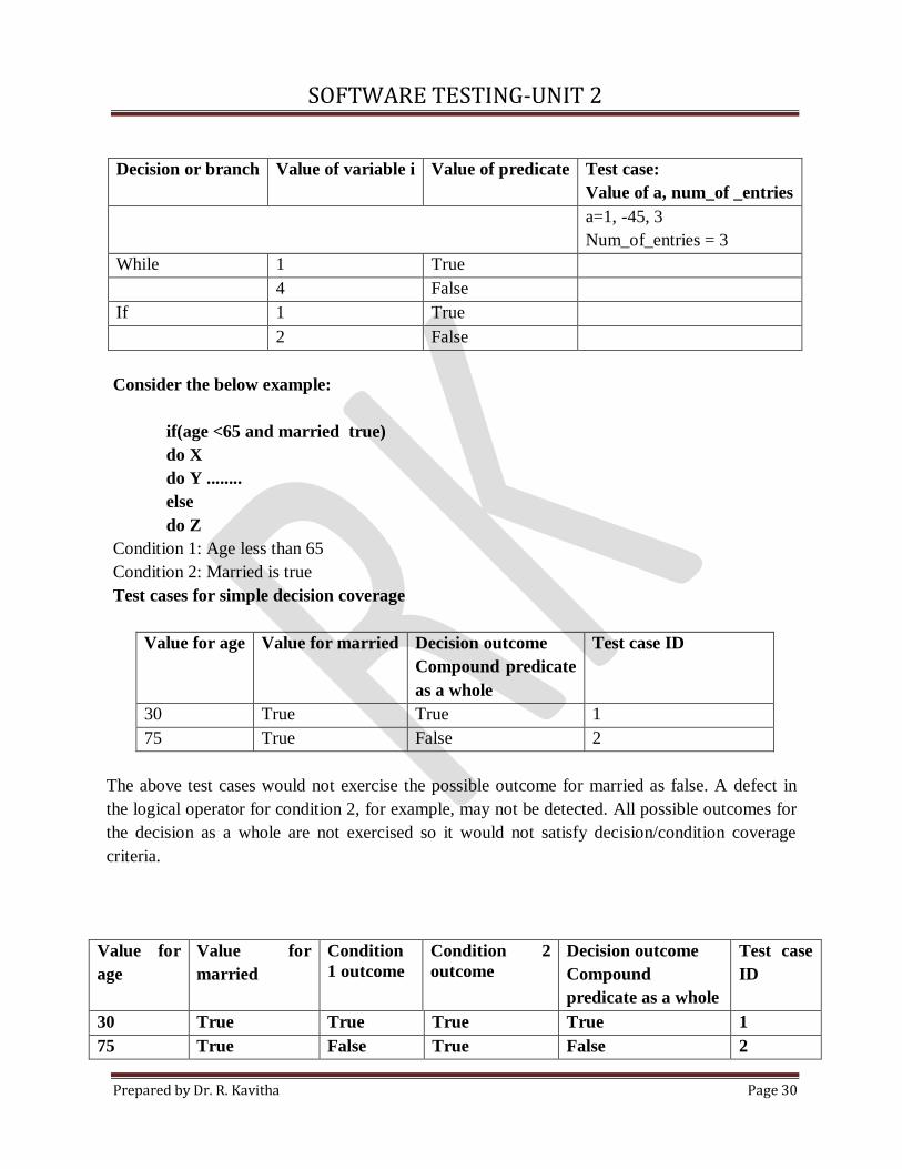
Decision or branch Value of variable i Value of predicate Test case:
Value of a, num_of _entries
a=1, -45, 3
Num_of_entries = 3
While 1 True
4 False
If 1 True
2 False
Consider the below example:
if(age <65 and married true)
do X
do Y ........
else
do Z
Condition 1: Age less than 65
Condition 2: Married is true
Test cases for simple decision coverage
Value for age Value for married Decision outcome
Compound predicate
as a whole
Test case ID
30 True True 1
75 True False 2
The above test cases would not exercise the possible outcome for married as false. A defect in
the logical operator for condition 2, for example, may not be detected. All possible outcomes for
the decision as a whole are not exercised so it would not satisfy decision/condition coverage
criteria.
Value for
age
Value for
married
Condition
1 outcome
Condition 2
outcome
Decision outcome
Compound
predicate as a whole
Test case
ID
30 True True True True 1
75 True False True False 2
SOFTWARE TESTING-UNIT 2
Prepared by Dr. R. Kavitha Page 31
30 False True False False 3
• The criteria described above do not require the coverage of all the possible combinations of
conditions.
• This is represented by yet another criterion called multiple condition coverage where all
possible combinations of condition outcomes in each decision must occur at least once
when the test cases are executed.
• That means the tester needs to satisfy the following combinations for the example decision
statement:
Condition 1 Condition 2
True False
True True
False True
False False
In most cases the stronger the coverage criterion, the larger the number of test cases that
must be developed to insure complete coverage.
*****
2.14. Path - White box testing
• Tools are available to generate control flow graphs. These tools typically calculate a value
for a software attribute called McCabe’s Cyclomatic Complexity V(G) from a flow graph.
• The cyclomatic complexity attribute is very useful to a tester.
• The complexity value is usually calculated from the control flow graph (G) by the formula
V(G) = E-N+2
E - number of edges in the control flow graph
N - number of nodes.
Here, E=7, N=6
V (G)= 3
Cyclomatic complexity value indicates the number of test cases needed for branch coverage in a
module of structured code.
• A path is a sequence of control flow nodes usually beginning from the entry node of a
graph through to the exit node.
• A path may go through a given segment of the control flow graph one or more times.
SOFTWARE TESTING-UNIT 2
Prepared by Dr. R. Kavitha Page 32
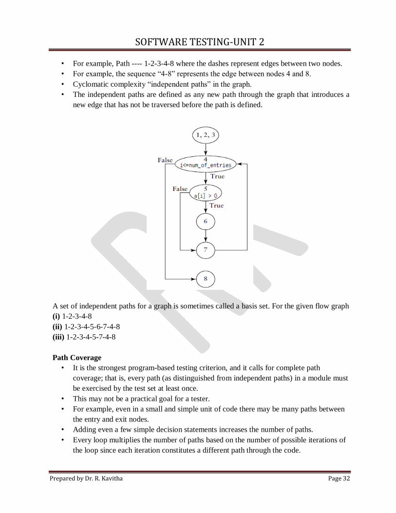
• For example, Path ---- 1-2-3-4-8 where the dashes represent edges between two nodes.
• For example, the sequence “4-8” represents the edge between nodes 4 and 8.
• Cyclomatic complexity “independent paths” in the graph.
• The independent paths are defined as any new path through the graph that introduces a
new edge that has not be traversed before the path is defined.
A set of independent paths for a graph is sometimes called a basis set. For the given flow graph
(i) 1-2-3-4-8
(ii) 1-2-3-4-5-6-7-4-8
(iii) 1-2-3-4-5-7-4-8
Path Coverage
• It is the strongest program-based testing criterion, and it calls for complete path
coverage; that is, every path (as distinguished from independent paths) in a module must
be exercised by the test set at least once.
• This may not be a practical goal for a tester.
• For example, even in a small and simple unit of code there may be many paths between
the entry and exit nodes.
• Adding even a few simple decision statements increases the number of paths.
• Every loop multiplies the number of paths based on the number of possible iterations of
the loop since each iteration constitutes a different path through the code.
SOFTWARE TESTING-UNIT 2
Prepared by Dr. R. Kavitha Page 33
• Thus, complete path coverage for even a simple module may not be practical, and for
large and complex modules it is not feasible.
• . Under these circumstances coverage goals are best expressed in terms of the number of
feasible or achievable paths, branches, or statements respectively.
• The basis set is a special set of paths and does not represent all the paths in a module; it
serves as a tool to aid the tester in achieving decision coverage.
*****
2.15 Error Guessing
• Error guessing is a test case design technique where the tester has to guess what faults
might occur and to design the tests to represent them.
• Previous testing knowledge – Helpful for current testing
Example:
Test cases for a pen
• To check the pen type
• To check the pen cap is present or not
• To check the pen ink is filled or not
• To check the pen writing or not
• To check the ink color i.e black or blue
• To check the pen color
• To check whether the pen is used to write all types of papers or not
• To check the ink capacity of the pen
• To check the pen product by fiber or plastic
*****
Recommended