Simple Cheap MMIC Preamps Who needs a GaAsFET?
Paul Wade W1GHZ ©2014 [email protected]
I have tried some of the newer MMICs from Minicircuits1 as moderate power amplifiers2,3,
providing several hundred milliwatts with good gain from VHF through the lower microwave
bands. Noise figures (NF) are reasonable for a power amplifier, perhaps 4 dB, so the dynamic
range is impressive.
At Microwave Update 2013, WA5VJB was selling LNA kits at a reasonable price – the kit
consisted of a MMIC and a PC board. The PCB was marked G4DDK/G8EMY/VJB, two guys
who know about LNA design, so I bought one to give it a try. The MMIC is a Minicircuits
PGA-103. The datasheet shows NF under 1 dB from 50 MHz up to 2 GHz. I put the kit together
and fired it up – the Noise Figure is under 1 dB at 144, 432, and 1296 MHz, all with no tuning.
Gain is 22.5 dB at 144 MHz, 20 dB at 432 MHz, and 12 dB at 1296 MHz. Not bad for a $1.99
device!
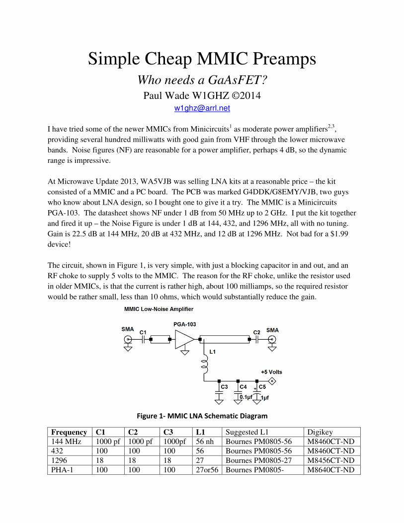
The circuit, shown in Figure 1, is very simple, with just a blocking capacitor in and out, and an
RF choke to supply 5 volts to the MMIC. The reason for the RF choke, unlike the resistor used
in older MMICs, is that the current is rather high, about 100 milliamps, so the required resistor
would be rather small, less than 10 ohms, which would substantially reduce the gain.
Figure 1- MMIC LNA Schematic Diagram
Frequency C1 C2 C3 L1 Suggested L1 Digikey
144 MHz 1000 pf 1000 pf 1000pf 56 nh Bournes PM0805-56 M8460CT-ND
432 100 100 100 56 Bournes PM0805-56 M8460CT-ND
1296 18 18 18 27 Bournes PM0805-27 M8456CT-ND
PHA-1 100 100 100 27or56 Bournes PM0805- M8640CT-ND
The WA5VJB PC board is intended to attach directly to small coax cables. This is probably
adequate for VHF, but not for microwave use. I used short lengths of thin semi-rigid coax,
shown in Figure 2, but it does not feel robust.
Figure 2 - MMIC Preamp on WA5VJB board
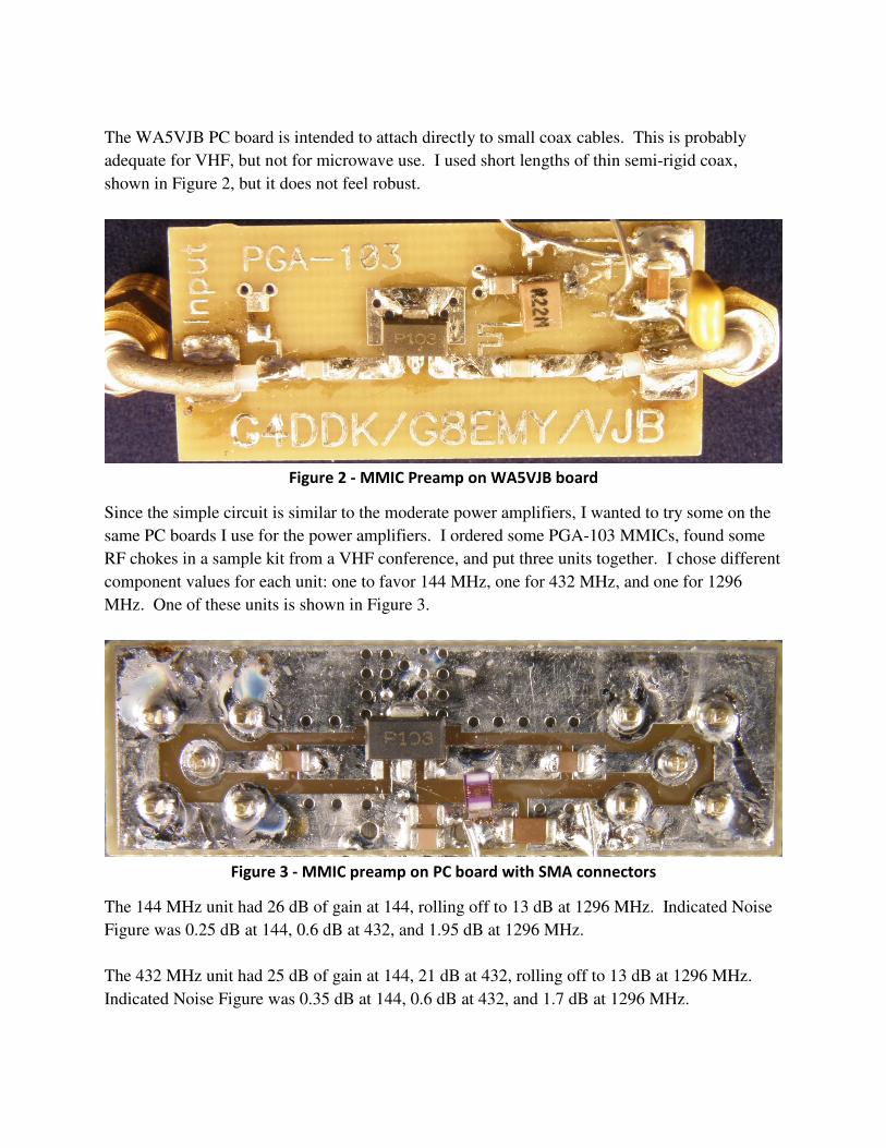
Since the simple circuit is similar to the moderate power amplifiers, I wanted to try some on the
same PC boards I use for the power amplifiers. I ordered some PGA-103 MMICs, found some
RF chokes in a sample kit from a VHF conference, and put three units together. I chose different
component values for each unit: one to favor 144 MHz, one for 432 MHz, and one for 1296
MHz. One of these units is shown in Figure 3.
Figure 3 - MMIC preamp on PC board with SMA connectors
The 144 MHz unit had 26 dB of gain at 144, rolling off to 13 dB at 1296 MHz. Indicated Noise
Figure was 0.25 dB at 144, 0.6 dB at 432, and 1.95 dB at 1296 MHz.
The 432 MHz unit had 25 dB of gain at 144, 21 dB at 432, rolling off to 13 dB at 1296 MHz.
Indicated Noise Figure was 0.35 dB at 144, 0.6 dB at 432, and 1.7 dB at 1296 MHz.
The 1296 MHz unit had 19 dB of gain at 144, 22 dB at 270 MHz, 20 dB at 432, rolling off to 14
dB at 1296 MHz. Indicated Noise Figure was 0.65 dB at 144, 0.6 dB at 432, and 1.65 dB at
1296 MHz. Correcting for the second stage at 1296 gives a calculated device NF of about 0.75
dB. Using the 432 MHz unit as a second stage at 1296 MHz brought the indicated NF down to
0.75 dB.
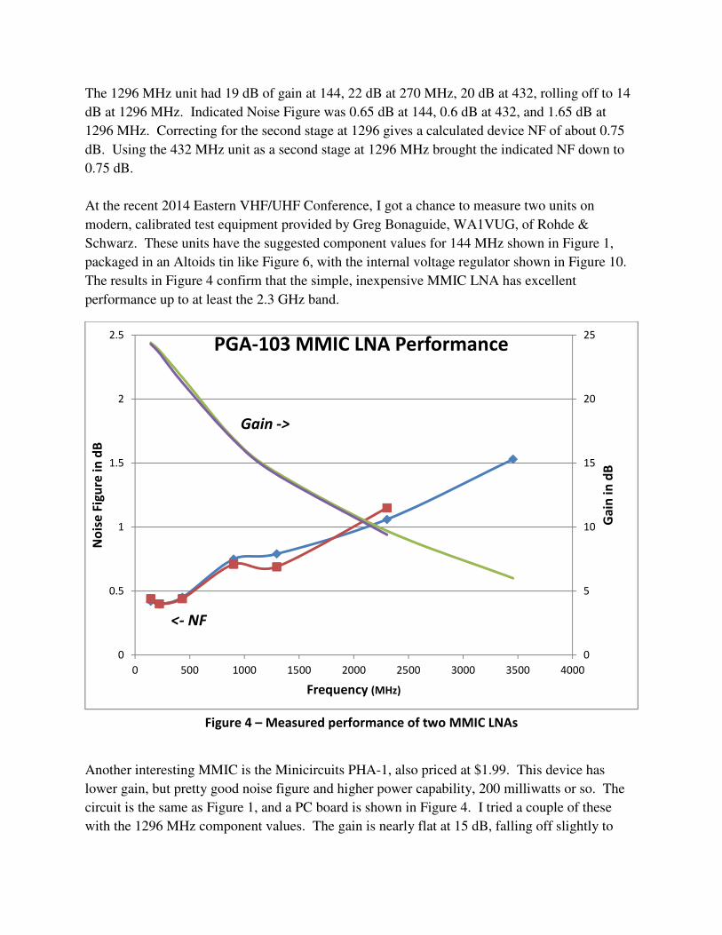
At the recent 2014 Eastern VHF/UHF Conference, I got a chance to measure two units on
modern, calibrated test equipment provided by Greg Bonaguide, WA1VUG, of Rohde &
Schwarz. These units have the suggested component values for 144 MHz shown in Figure 1,
packaged in an Altoids tin like Figure 6, with the internal voltage regulator shown in Figure 10.
The results in Figure 4 confirm that the simple, inexpensive MMIC LNA has excellent
performance up to at least the 2.3 GHz band.
Figure 4 – Measured performance of two MMIC LNAs
Another interesting MMIC is the Minicircuits PHA-1, also priced at $1.99. This device has
lower gain, but pretty good noise figure and higher power capability, 200 milliwatts or so. The
circuit is the same as Figure 1, and a PC board is shown in Figure 4. I tried a couple of these
with the 1296 MHz component values. The gain is nearly flat at 15 dB, falling off slightly to
0
5
10
15
20
25
0
0.5
1
1.5
2
2.5
0 500 1000 1500 2000 2500 3000 3500 4000
Ga
in i
n d
B
No
ise
Fig
ure
in
dB
Frequency (MHz)
PGA-103 MMIC LNA Performance
Gain ->
<- NF
about 13 dB at 1296 MHz. Noise Figure is also flat, about 2 dB at 144, 432, and1296 MHz.
This one might be a good choice for a second stage.With appropriate component values, it might
make a terrific 6-meter preamp with high dynamic range; most rigs don’t need a preamp at six
meters, but some of the SDR rigs can use one.
Tuning
A really nice feature of these MMICs is that no tuning is required to get really good
performance. The input and output are quite well matched, with Return Loss better than 10 dB
over the whole frequency range, so tuning is probably not going to provide a whole lot of
improvement.
Providing a low NF with a matched input is quite a contrast to a typical LNA, which might have
an input reflection coefficient upward of 0.9 – highly mismatched – when tuned for best NF.
We know that a high VSWR increases transmission line loss; does this apply to the LNA as
well? A low-VSWR MMIC with a slightly higher NF might reduce cable loss and provide better
system performance than a mismatched LNA. EME operators know that putting the LNA right
at the antenna eliminates transmission line loss and provides best performance.
Construction
These MMICs are in a small plastic SOT-89 package with three leads – the center lead is ground,
and connects to a heatsink paddle on the bottom of the package. As
mentioned earlier, these devices draw roughly 100 mA at 5 Volts, so ½
watt is dissipated. Dead-bug construction will not work, heat sinking is
required. The PC boards have a number of plated-thru holes under the
ground lead and paddle to conduct the heat to the ground plane side of the
board. This seems adequate – the MMIC temperature is reasonable, according to one of my ten
precision temperature sensors.
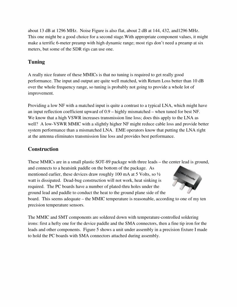
The MMIC and SMT components are soldered down with temperature-controlled soldering
irons: first a hefty one for the device paddle and the SMA connectors, then a fine tip iron for the
leads and other components. Figure 5 shows a unit under assembly in a precision fixture I made
to hold the PC boards with SMA connectors attached during assembly.
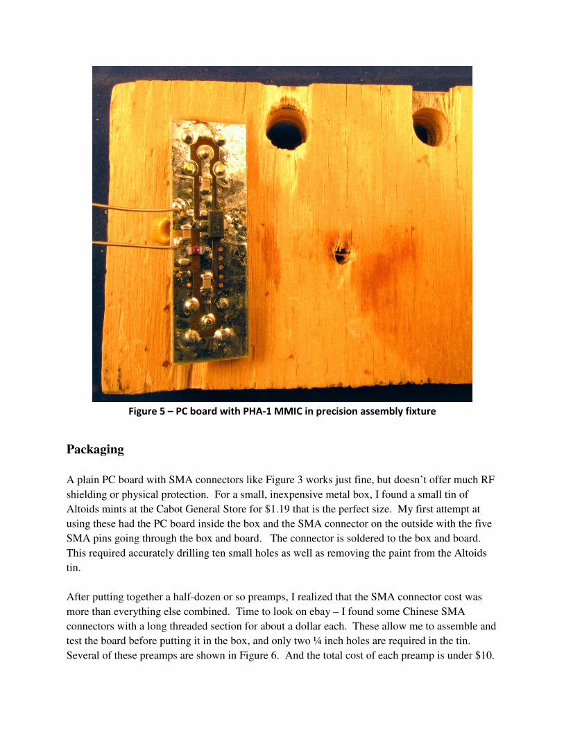
Figure 5 – PC board with PHA-1 MMIC in precision assembly fixture
Packaging
A plain PC board with SMA connectors like Figure 3 works just fine, but doesn’t offer much RF
shielding or physical protection. For a small, inexpensive metal box, I found a small tin of
Altoids mints at the Cabot General Store for $1.19 that is the perfect size. My first attempt at
using these had the PC board inside the box and the SMA connector on the outside with the five
SMA pins going through the box and board. The connector is soldered to the box and board.
This required accurately drilling ten small holes as well as removing the paint from the Altoids
tin.
After putting together a half-dozen or so preamps, I realized that the SMA connector cost was
more than everything else combined. Time to look on ebay – I found some Chinese SMA
connectors with a long threaded section for about a dollar each. These allow me to assemble and
test the board before putting it in the box, and only two ¼ inch holes are required in the tin.
Several of these preamps are shown in Figure 6. And the total cost of each preamp is under $10.
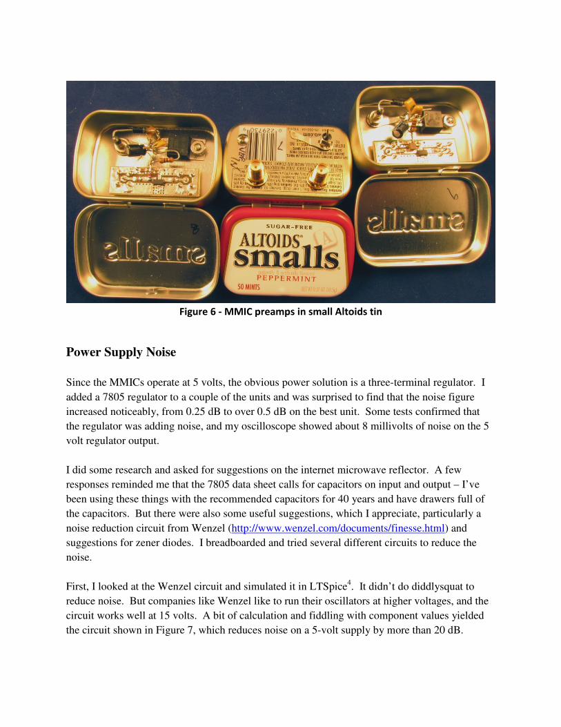
Figure 6 - MMIC preamps in small Altoids tin
Power Supply Noise
Since the MMICs operate at 5 volts, the obvious power solution is a three-terminal regulator. I
added a 7805 regulator to a couple of the units and was surprised to find that the noise figure
increased noticeably, from 0.25 dB to over 0.5 dB on the best unit. Some tests confirmed that
the regulator was adding noise, and my oscilloscope showed about 8 millivolts of noise on the 5
volt regulator output.
I did some research and asked for suggestions on the internet microwave reflector. A few
responses reminded me that the 7805 data sheet calls for capacitors on input and output – I’ve
been using these things with the recommended capacitors for 40 years and have drawers full of
the capacitors. But there were also some useful suggestions, which I appreciate, particularly a
noise reduction circuit from Wenzel (http://www.wenzel.com/documents/finesse.html) and
suggestions for zener diodes. I breadboarded and tried several different circuits to reduce the
noise.
First, I looked at the Wenzel circuit and simulated it in LTSpice4. It didn’t do diddlysquat to
reduce noise. But companies like Wenzel like to run their oscillators at higher voltages, and the
circuit works well at 15 volts. A bit of calculation and fiddling with component values yielded
the circuit shown in Figure 7, which reduces noise on a 5-volt supply by more than 20 dB.

Figure 7 - Wenzel noise reduction circuit modified for 5 Volt operation
Another suggestion was the classic capacitance multiplier, shown in Figure 8.
Figure 8 - Capacitance Multiplier for noise reduction
Zener diodes are often used in GaAsFET and HEMT preamps operating at low voltages, but
those devices operate at much lower currents. (Zener is a misnomer – true zener diodes operate
at 6 to 7 volts, while other voltages are really avalanche diodes, just like RF noise sources. The
difference is that noise source diodes have very low capacitance, while power “zener” diodes
have enough capacitance to limit noise at VHF and higher frequencies). For a 5 volt zener diode
to provide 100 mA from a 12 volt battery (perhaps 11 to 15 volt range), a lot of power would be
wasted in the zener and dropping resistor. However, most of my transverters operate on 8 volts
from an internal regulator – having a fixed input voltage makes the zener practical, as shown in
Figure 9, because we don’t have to waste as much current to allow for a wide input voltage
range.
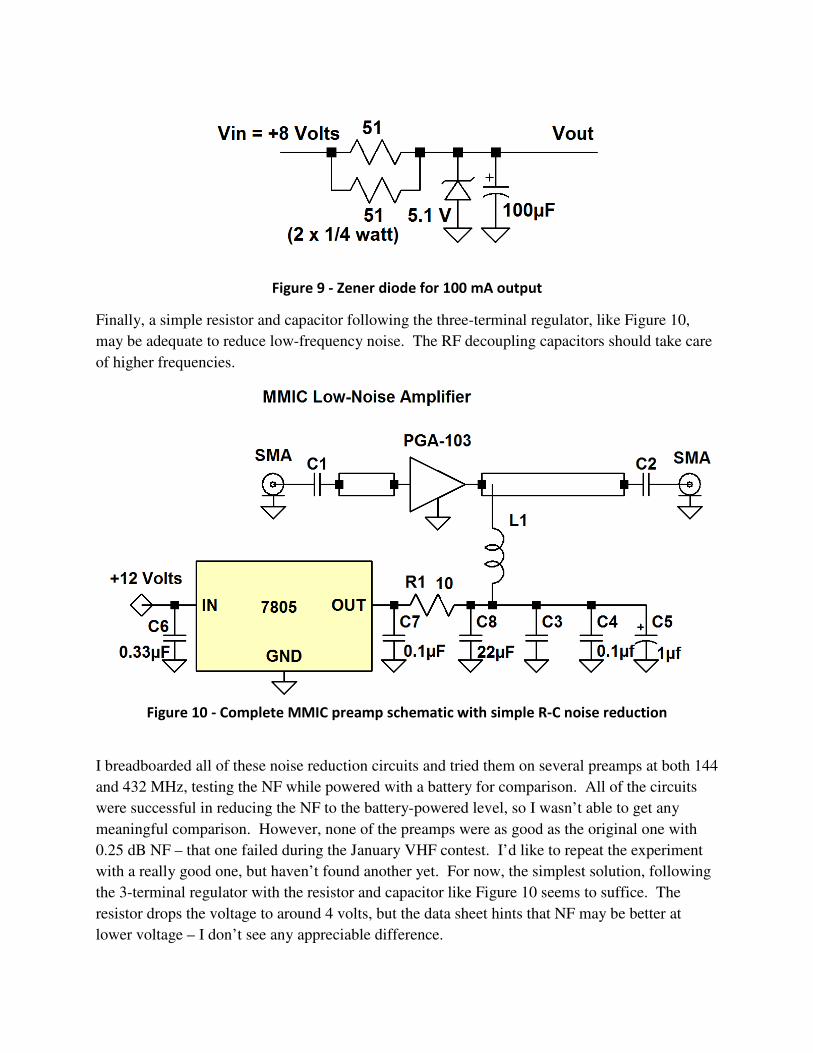
Figure 9 - Zener diode for 100 mA output
Finally, a simple resistor and capacitor following the three-terminal regulator, like Figure 10,
may be adequate to reduce low-frequency noise. The RF decoupling capacitors should take care
of higher frequencies.
Figure 10 - Complete MMIC preamp schematic with simple R-C noise reduction
I breadboarded all of these noise reduction circuits and tried them on several preamps at both 144
and 432 MHz, testing the NF while powered with a battery for comparison. All of the circuits
were successful in reducing the NF to the battery-powered level, so I wasn’t able to get any
meaningful comparison. However, none of the preamps were as good as the original one with
0.25 dB NF – that one failed during the January VHF contest. I’d like to repeat the experiment
with a really good one, but haven’t found another yet. For now, the simplest solution, following
the 3-terminal regulator with the resistor and capacitor like Figure 10 seems to suffice. The
resistor drops the voltage to around 4 volts, but the data sheet hints that NF may be better at
lower voltage – I don’t see any appreciable difference.
Several complete preamps in small Altoids tins are shown in Figure 6. The regulator and noise
reduction circuit is dead-bug wiring. Note that an idiot diode in series with the input voltage is
missing from the schematic diagram, but included in each preamp.
Oscillations
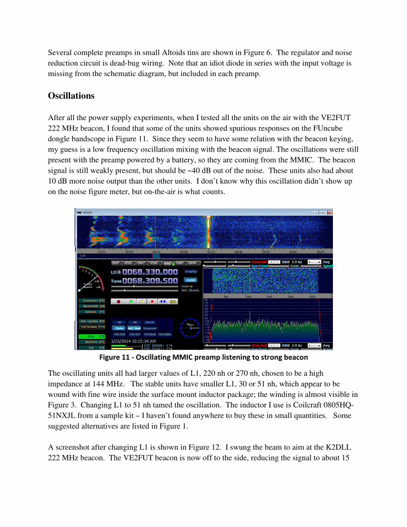
After all the power supply experiments, when I tested all the units on the air with the VE2FUT
222 MHz beacon, I found that some of the units showed spurious responses on the FUncube
dongle bandscope in Figure 11. Since they seem to have some relation with the beacon keying,
my guess is a low frequency oscillation mixing with the beacon signal. The oscillations were still
present with the preamp powered by a battery, so they are coming from the MMIC. The beacon
signal is still weakly present, but should be ~40 dB out of the noise. These units also had about
10 dB more noise output than the other units. I don’t know why this oscillation didn’t show up
on the noise figure meter, but on-the-air is what counts.
Figure 11 - Oscillating MMIC preamp listening to strong beacon
The oscillating units all had larger values of L1, 220 nh or 270 nh, chosen to be a high
impedance at 144 MHz. The stable units have smaller L1, 30 or 51 nh, which appear to be
wound with fine wire inside the surface mount inductor package; the winding is almost visible in
Figure 3. Changing L1 to 51 nh tamed the oscillation. The inductor I use is Coilcraft 0805HQ-
51NXJL from a sample kit – I haven’t found anywhere to buy these in small quantities. Some
suggested alternatives are listed in Figure 1.
A screenshot after changing L1 is shown in Figure 12. I swung the beam to aim at the K2DLL
222 MHz beacon. The VE2FUT beacon is now off to the side, reducing the signal to about 15
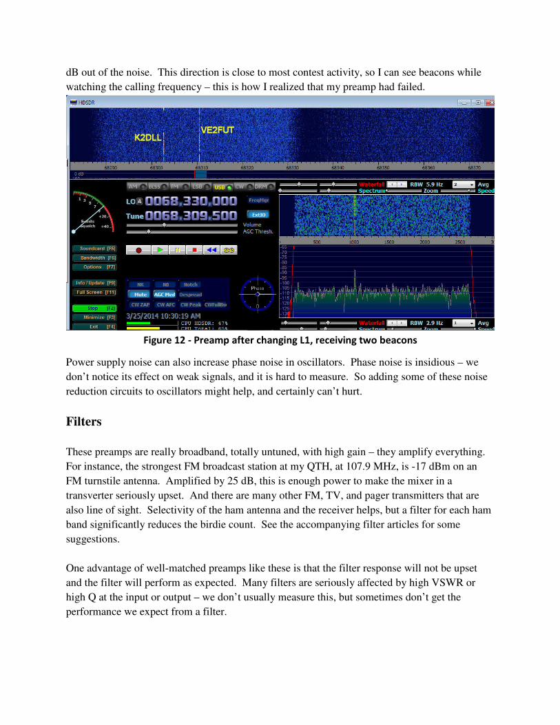
dB out of the noise. This direction is close to most contest activity, so I can see beacons while
watching the calling frequency – this is how I realized that my preamp had failed.
Figure 12 - Preamp after changing L1, receiving two beacons
Power supply noise can also increase phase noise in oscillators. Phase noise is insidious – we
don’t notice its effect on weak signals, and it is hard to measure. So adding some of these noise
reduction circuits to oscillators might help, and certainly can’t hurt.
Filters
These preamps are really broadband, totally untuned, with high gain – they amplify everything.
For instance, the strongest FM broadcast station at my QTH, at 107.9 MHz, is -17 dBm on an
FM turnstile antenna. Amplified by 25 dB, this is enough power to make the mixer in a
transverter seriously upset. And there are many other FM, TV, and pager transmitters that are
also line of sight. Selectivity of the ham antenna and the receiver helps, but a filter for each ham
band significantly reduces the birdie count. See the accompanying filter articles for some
suggestions.
One advantage of well-matched preamps like these is that the filter response will not be upset
and the filter will perform as expected. Many filters are seriously affected by high VSWR or
high Q at the input or output – we don’t usually measure this, but sometimes don’t get the
performance we expect from a filter.
Summary
These MMICs make a great LNA which is simple, cheap, and easy to build. Putting one in front
of a pretty good transverter makes the band really come alive. Performance is not quite as good
as the best HEMT LNAs, but close enough for all terrestrial work and for EME below 432 MHz,
frequencies where atmospheric and local noise is the limiting factor. Even for EME on the
higher bands, these preamps would make a great second stage.
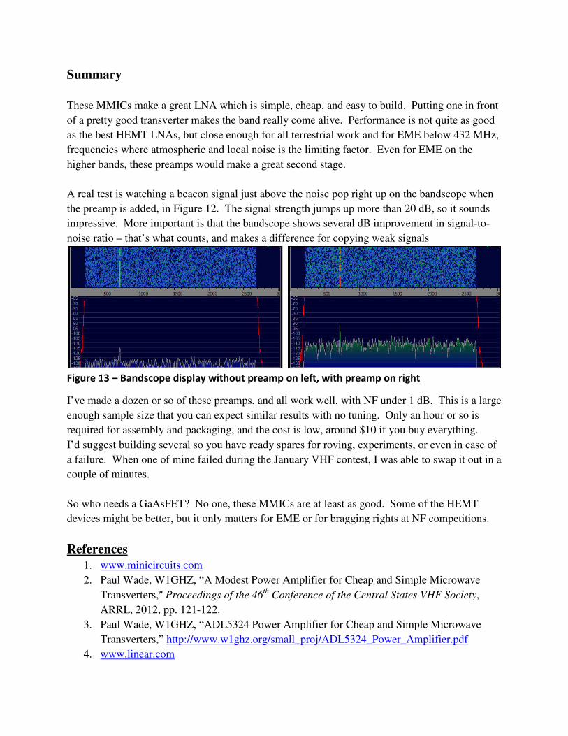
A real test is watching a beacon signal just above the noise pop right up on the bandscope when
the preamp is added, in Figure 12. The signal strength jumps up more than 20 dB, so it sounds
impressive. More important is that the bandscope shows several dB improvement in signal-to-
noise ratio – that’s what counts, and makes a difference for copying weak signals
Figure 13 – Bandscope display without preamp on left, with preamp on right
I’ve made a dozen or so of these preamps, and all work well, with NF under 1 dB. This is a large
enough sample size that you can expect similar results with no tuning. Only an hour or so is
required for assembly and packaging, and the cost is low, around $10 if you buy everything.
I’d suggest building several so you have ready spares for roving, experiments, or even in case of
a failure. When one of mine failed during the January VHF contest, I was able to swap it out in a
couple of minutes.
So who needs a GaAsFET? No one, these MMICs are at least as good. Some of the HEMT
devices might be better, but it only matters for EME or for bragging rights at NF competitions.
References
1. www.minicircuits.com
2. Paul Wade, W1GHZ, “A Modest Power Amplifier for Cheap and Simple Microwave
Transverters,” Proceedings of the 46th
Conference of the Central States VHF Society,
ARRL, 2012, pp. 121-122.
3. Paul Wade, W1GHZ, “ADL5324 Power Amplifier for Cheap and Simple Microwave
Transverters,” http://www.w1ghz.org/small_proj/ADL5324_Power_Amplifier.pdf
4. www.linear.com
Recommended