S7-300 Instruction List
CPU 31xC, CPU 31x, IM 151-7 CPU, IM 151-8 CPU, IM 154-8 CPU, BM 147-1 CPU, BM 147-2 CPU
This instruction list is part of thedocumentation package with the order number:
6ES7398-8FA10-8BA06ES7198-8FA01-8BA0
06/2008A5E00105517-10
We have checked the contents of this manual for agreement with thehardware and software described. Since deviations cannot be pre-cluded entirely, we cannot guarantee full agreement. However, thedata in this manual are reviewed regularly and any necessary cor-rections included in subsequent editions. Suggestions for improve-ment are welcomed.
Disclaim of LiabilityCopyright � Siemens AG 2008 All rights reserved
The reproduction, transmission or use of this document or itscontents is not permitted without express written authority.Offenders will be liable for damages. All rights, including rightscreated by patent grant or registration of a utility model or design, arereserved.
Siemens AGIndustry SectorPostfach 484890437 NÜRNBERG / GERMANY
© Siemens AG 2008Technical data subject to change.
A5E00105517-10
Contents
1S7-300 Instruction list, CPU 31xC, CPU 31x, IM 151-7 CPU, IM 151-8 CPU, IM 154-8 CPU, BM 147-1 CPU, BM 147-2 CPU A5E00105517-10
Contents
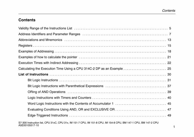
Validity Range of the Instructions List 5. . . . . . . . . . . . . . . . . . . . . . . . . . . . . . . . . . . . . . . . . . . . . . . . . . . . . . . . .
Address Identifiers and Parameter Ranges 7. . . . . . . . . . . . . . . . . . . . . . . . . . . . . . . . . . . . . . . . . . . . . . . . . . . .
Abbreviations and Mnemonics 13. . . . . . . . . . . . . . . . . . . . . . . . . . . . . . . . . . . . . . . . . . . . . . . . . . . . . . . . . . . . . .
Registers 15. . . . . . . . . . . . . . . . . . . . . . . . . . . . . . . . . . . . . . . . . . . . . . . . . . . . . . . . . . . . . . . . . . . . . . . . . . . . . . . . .
Examples of Addressing 18. . . . . . . . . . . . . . . . . . . . . . . . . . . . . . . . . . . . . . . . . . . . . . . . . . . . . . . . . . . . . . . . . . . .
Examples of how to calculate the pointer 21. . . . . . . . . . . . . . . . . . . . . . . . . . . . . . . . . . . . . . . . . . . . . . . . . . . . .
Execution Times with Indirect Addressing 22. . . . . . . . . . . . . . . . . . . . . . . . . . . . . . . . . . . . . . . . . . . . . . . . . . . . .
Calculating the Execution Time Using a CPU 314C-2 DP as an Example 25. . . . . . . . . . . . . . . . . . . . . . . . . .
List of Instructions 30. . . . . . . . . . . . . . . . . . . . . . . . . . . . . . . . . . . . . . . . . . . . . . . . . . . . . . . . . . . . . . . . . . . . . . .
Bit Logic Instructions 31. . . . . . . . . . . . . . . . . . . . . . . . . . . . . . . . . . . . . . . . . . . . . . . . . . . . . . . . . . . . . . . . .
Bit Logic Instructions with Parenthetical Expressions 37. . . . . . . . . . . . . . . . . . . . . . . . . . . . . . . . . . . . .
ORing of AND Operations 39. . . . . . . . . . . . . . . . . . . . . . . . . . . . . . . . . . . . . . . . . . . . . . . . . . . . . . . . . . . .
Logic Instructions with Timers and Counters 40. . . . . . . . . . . . . . . . . . . . . . . . . . . . . . . . . . . . . . . . . . . . .
Word Logic Instructions with the Contents of Accumulator 1 45. . . . . . . . . . . . . . . . . . . . . . . . . . . . . . .
Evaluating Conditions Using AND, OR and EXCLUSIVE OR 47. . . . . . . . . . . . . . . . . . . . . . . . . . . . . . .
Edge-Triggered Instructions 49. . . . . . . . . . . . . . . . . . . . . . . . . . . . . . . . . . . . . . . . . . . . . . . . . . . . . . . . . . .
Contents
2S7-300 Instruction list, CPU 31xC, CPU 31x, IM 151-7 CPU, IM 151-8 CPU, IM 154-8 CPU, BM 147-1 CPU, BM 147-2 CPU A5E00105517-10
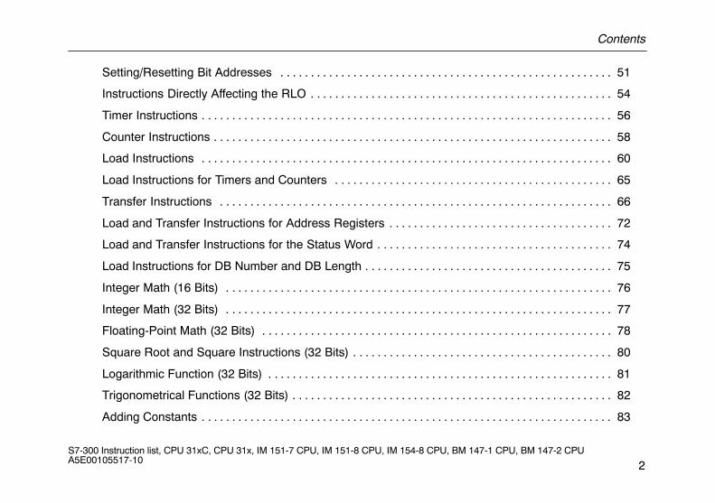
Setting/Resetting Bit Addresses 51. . . . . . . . . . . . . . . . . . . . . . . . . . . . . . . . . . . . . . . . . . . . . . . . . . . . . . .
Instructions Directly Affecting the RLO 54. . . . . . . . . . . . . . . . . . . . . . . . . . . . . . . . . . . . . . . . . . . . . . . . . .
Timer Instructions 56. . . . . . . . . . . . . . . . . . . . . . . . . . . . . . . . . . . . . . . . . . . . . . . . . . . . . . . . . . . . . . . . . . . .
Counter Instructions 58. . . . . . . . . . . . . . . . . . . . . . . . . . . . . . . . . . . . . . . . . . . . . . . . . . . . . . . . . . . . . . . . . .
Load Instructions 60. . . . . . . . . . . . . . . . . . . . . . . . . . . . . . . . . . . . . . . . . . . . . . . . . . . . . . . . . . . . . . . . . . . .
Load Instructions for Timers and Counters 65. . . . . . . . . . . . . . . . . . . . . . . . . . . . . . . . . . . . . . . . . . . . . .
Transfer Instructions 66. . . . . . . . . . . . . . . . . . . . . . . . . . . . . . . . . . . . . . . . . . . . . . . . . . . . . . . . . . . . . . . . .
Load and Transfer Instructions for Address Registers 72. . . . . . . . . . . . . . . . . . . . . . . . . . . . . . . . . . . . .
Load and Transfer Instructions for the Status Word 74. . . . . . . . . . . . . . . . . . . . . . . . . . . . . . . . . . . . . . .
Load Instructions for DB Number and DB Length 75. . . . . . . . . . . . . . . . . . . . . . . . . . . . . . . . . . . . . . . . .
Integer Math (16 Bits) 76. . . . . . . . . . . . . . . . . . . . . . . . . . . . . . . . . . . . . . . . . . . . . . . . . . . . . . . . . . . . . . . .
Integer Math (32 Bits) 77. . . . . . . . . . . . . . . . . . . . . . . . . . . . . . . . . . . . . . . . . . . . . . . . . . . . . . . . . . . . . . . .
Floating-Point Math (32 Bits) 78. . . . . . . . . . . . . . . . . . . . . . . . . . . . . . . . . . . . . . . . . . . . . . . . . . . . . . . . . .
Square Root and Square Instructions (32 Bits) 80. . . . . . . . . . . . . . . . . . . . . . . . . . . . . . . . . . . . . . . . . . .
Logarithmic Function (32 Bits) 81. . . . . . . . . . . . . . . . . . . . . . . . . . . . . . . . . . . . . . . . . . . . . . . . . . . . . . . . .
Trigonometrical Functions (32 Bits) 82. . . . . . . . . . . . . . . . . . . . . . . . . . . . . . . . . . . . . . . . . . . . . . . . . . . . .
Adding Constants 83. . . . . . . . . . . . . . . . . . . . . . . . . . . . . . . . . . . . . . . . . . . . . . . . . . . . . . . . . . . . . . . . . . . .
Contents
3S7-300 Instruction list, CPU 31xC, CPU 31x, IM 151-7 CPU, IM 151-8 CPU, IM 154-8 CPU, BM 147-1 CPU, BM 147-2 CPU A5E00105517-10
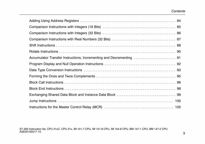
Adding Using Address Registers 84. . . . . . . . . . . . . . . . . . . . . . . . . . . . . . . . . . . . . . . . . . . . . . . . . . . . . . .
Comparison Instructions with Integers (16 Bits) 85. . . . . . . . . . . . . . . . . . . . . . . . . . . . . . . . . . . . . . . . . .
Comparison Instructions with Integers (32 Bits) 86. . . . . . . . . . . . . . . . . . . . . . . . . . . . . . . . . . . . . . . . . .
Comparison Instructions with Real Numbers (32 Bits) 87. . . . . . . . . . . . . . . . . . . . . . . . . . . . . . . . . . . . .
Shift Instructions 88. . . . . . . . . . . . . . . . . . . . . . . . . . . . . . . . . . . . . . . . . . . . . . . . . . . . . . . . . . . . . . . . . . . . .
Rotate Instructions 90. . . . . . . . . . . . . . . . . . . . . . . . . . . . . . . . . . . . . . . . . . . . . . . . . . . . . . . . . . . . . . . . . . .
Accumulator Transfer Instructions, Incrementing and Decrementing 91. . . . . . . . . . . . . . . . . . . . . . . .
Program Display and Null Operation Instructions 92. . . . . . . . . . . . . . . . . . . . . . . . . . . . . . . . . . . . . . . . .
Data Type Conversion Instructions 93. . . . . . . . . . . . . . . . . . . . . . . . . . . . . . . . . . . . . . . . . . . . . . . . . . . . .
Forming the Ones and Twos Complements 95. . . . . . . . . . . . . . . . . . . . . . . . . . . . . . . . . . . . . . . . . . . . . .
Block Call Instructions 96. . . . . . . . . . . . . . . . . . . . . . . . . . . . . . . . . . . . . . . . . . . . . . . . . . . . . . . . . . . . . . . .
Block End Instructions 98. . . . . . . . . . . . . . . . . . . . . . . . . . . . . . . . . . . . . . . . . . . . . . . . . . . . . . . . . . . . . . . .
Exchanging Shared Data Block and Instance Data Block 99. . . . . . . . . . . . . . . . . . . . . . . . . . . . . . . . . .
Jump Instructions 100. . . . . . . . . . . . . . . . . . . . . . . . . . . . . . . . . . . . . . . . . . . . . . . . . . . . . . . . . . . . . . . . . . .
Instructions for the Master Control Relay (MCR) 105. . . . . . . . . . . . . . . . . . . . . . . . . . . . . . . . . . . . . . . .
Contents
4S7-300 Instruction list, CPU 31xC, CPU 31x, IM 151-7 CPU, IM 151-8 CPU, IM 154-8 CPU, BM 147-1 CPU, BM 147-2 CPU A5E00105517-10
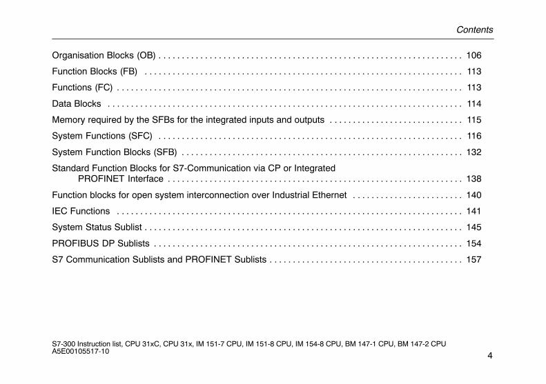
Organisation Blocks (OB) 106. . . . . . . . . . . . . . . . . . . . . . . . . . . . . . . . . . . . . . . . . . . . . . . . . . . . . . . . . . . . . . . . . .
Function Blocks (FB) 113. . . . . . . . . . . . . . . . . . . . . . . . . . . . . . . . . . . . . . . . . . . . . . . . . . . . . . . . . . . . . . . . . . . . .
Functions (FC) 113. . . . . . . . . . . . . . . . . . . . . . . . . . . . . . . . . . . . . . . . . . . . . . . . . . . . . . . . . . . . . . . . . . . . . . . . . . .
Data Blocks 114. . . . . . . . . . . . . . . . . . . . . . . . . . . . . . . . . . . . . . . . . . . . . . . . . . . . . . . . . . . . . . . . . . . . . . . . . . . . .
Memory required by the SFBs for the integrated inputs and outputs 115. . . . . . . . . . . . . . . . . . . . . . . . . . . . .
System Functions (SFC) 116. . . . . . . . . . . . . . . . . . . . . . . . . . . . . . . . . . . . . . . . . . . . . . . . . . . . . . . . . . . . . . . . . .
System Function Blocks (SFB) 132. . . . . . . . . . . . . . . . . . . . . . . . . . . . . . . . . . . . . . . . . . . . . . . . . . . . . . . . . . . . .
Standard Function Blocks for S7-Communication via CP or Integrated PROFINET Interface 138. . . . . . . . . . . . . . . . . . . . . . . . . . . . . . . . . . . . . . . . . . . . . . . . . . . . . . . . . . . . . . . .
Function blocks for open system interconnection over Industrial Ethernet 140. . . . . . . . . . . . . . . . . . . . . . . .
IEC Functions 141. . . . . . . . . . . . . . . . . . . . . . . . . . . . . . . . . . . . . . . . . . . . . . . . . . . . . . . . . . . . . . . . . . . . . . . . . . .
System Status Sublist 145. . . . . . . . . . . . . . . . . . . . . . . . . . . . . . . . . . . . . . . . . . . . . . . . . . . . . . . . . . . . . . . . . . . . .
PROFIBUS DP Sublists 154. . . . . . . . . . . . . . . . . . . . . . . . . . . . . . . . . . . . . . . . . . . . . . . . . . . . . . . . . . . . . . . . . . .
S7 Communication Sublists and PROFINET Sublists 157. . . . . . . . . . . . . . . . . . . . . . . . . . . . . . . . . . . . . . . . . .
Validity Range of the Instructions List
5S7-300 Instruction list, CPU 31xC, CPU 31x, IM 151-7 CPU, IM 151-8 CPU, IM 154-8 CPU, BM 147-1 CPU, BM 147-2 CPU A5E00105517-10
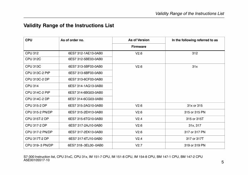
Validity Range of the Instructions List
CPU As of order no.
As of Version In the following referred to as
Firmware
CPU 312 6ES7 312-1AE13-0AB0 V2.6 312
CPU 312C 6ES7 312-5BE03-0AB0
CPU 313C 6ES7 313-5BF03-0AB0 V2.6 31x
CPU 313C-2 PtP 6ES7 313-6BF03-0AB0
CPU 313C-2 DP 6ES7 313-6CF03-0AB0
CPU 314 6ES7 314-1AG13-0AB0
CPU 314C-2 PtP 6ES7 314-6BG03-0AB0
CPU 314C-2 DP 6ES7 314-6CG03-0AB0
CPU 315-2 DP 6ES7 315-2AG10-0AB0 V2.6 31x or 315
CPU 315-2 PN/DP 6ES7 315-2EH13-0AB0 V2.6 315 or 315 PN
CPU 315T-2 DP 6ES7 315-6TG10-0AB0 V2.4 315 or 315T
CPU 317-2 DP 6ES7 317-2AJ10-0AB0 V2.6 31x, 317
CPU 317-2 PN/DP 6ES7 317-2EK13-0AB0 V2.6 317 or 317 PN
CPU 317T-2 DP 6ES7 317-6TJ10-0AB0 V2.4 317 or 317T
CPU 319–3 PN/DP 6ES7 318–3EL00–0AB0 V2.7 319 or 319 PN
Validity Range of the Instructions List
6S7-300 Instruction list, CPU 31xC, CPU 31x, IM 151-7 CPU, IM 151-8 CPU, IM 154-8 CPU, BM 147-1 CPU, BM 147-2 CPU A5E00105517-10
CPU As of order no.
As of Version In the following referred to as
Firmware
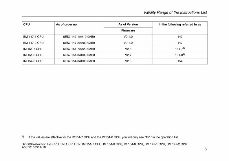
BM 147-1 CPU 6ES7 147-1AA10-0AB0 V2.1.0 147
BM 147-2 CPU 6ES7 147-2AA00-0XB0 V2.1.0 147
IM 151-7 CPU 6ES7 151-7AA20-0AB0 V2.6 151-71)
IM 151-8 CPU 6ES7 151-8AB00-0AB0 V2.7 151-81)
IM 154-8 CPU 6ES7 154-8AB00-0AB0 V2.5 154
1) If the values are effective for the IM151-7 CPU and the IM151-8 CPU. you will only see “151” in the operation list.
Address Identifiers and Parameter Ranges
7S7-300 Instruction list, CPU 31xC, CPU 31x, IM 151-7 CPU, IM 151-8 CPU, IM 154-8 CPU, BM 147-1 CPU, BM 147-2 CPU A5E00105517-10
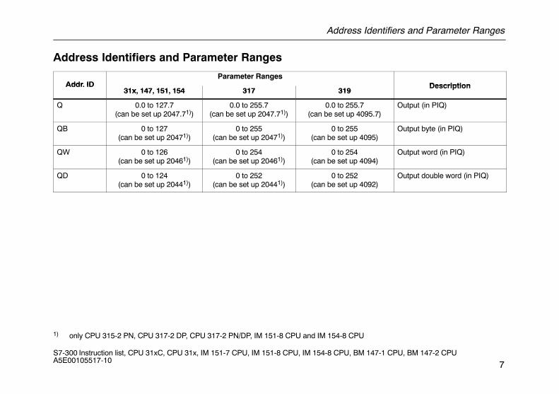
Address Identifiers and Parameter Ranges
Addr IDParameter Ranges
DescriptionAddr. ID31x 147 151 154 317 319
Description31x, 147, 151, 154 317 319
p
Q 0.0 to 127.7(can be set up 2047.71))
0.0 to 255.7(can be set up 2047.71))
0.0 to 255.7(can be set up 4095.7)
Output (in PIQ)
QB 0 to 127(can be set up 20471))
0 to 255(can be set up 20471))
0 to 255(can be set up 4095)
Output byte (in PIQ)
QW 0 to 126(can be set up 20461))
0 to 254(can be set up 20461))
0 to 254(can be set up 4094)
Output word (in PIQ)
QD 0 to 124(can be set up 20441))
0 to 252(can be set up 20441))
0 to 252(can be set up 4092)
Output double word (in PIQ)
1) only CPU 315-2 PN, CPU 317-2 DP, CPU 317-2 PN/DP, IM 151-8 CPU and IM 154-8 CPU
Address Identifiers and Parameter Ranges
8S7-300 Instruction list, CPU 31xC, CPU 31x, IM 151-7 CPU, IM 151-8 CPU, IM 154-8 CPU, BM 147-1 CPU, BM 147-2 CPU A5E00105517-10
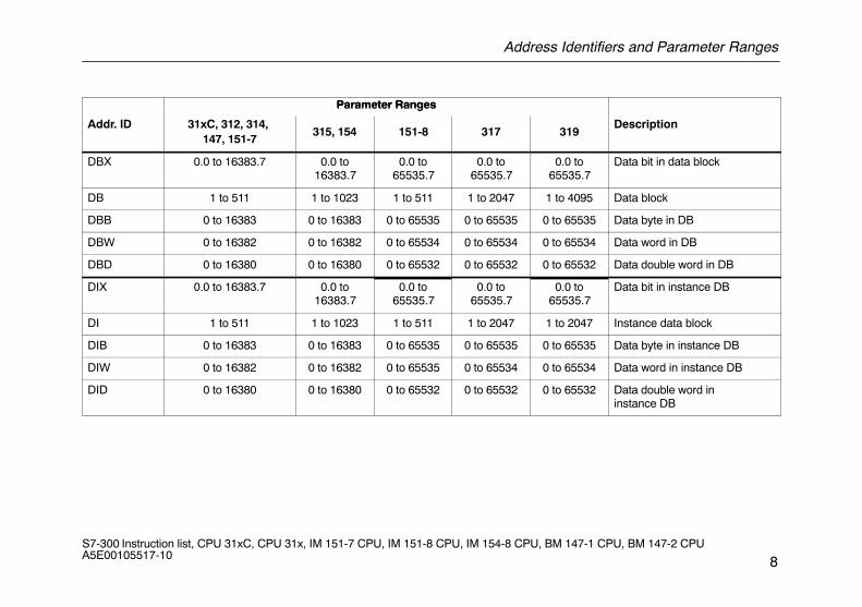
Parameter RangesParameter Ranges
Addr. ID 31xC, 312, 314, 147, 151-7
315, 154 151-8 317 319Description
DBX 0.0 to 16383.7 0.0 to16383.7
0.0 to65535.7
0.0 to65535.7
0.0 to65535.7
Data bit in data block
DB 1 to 511 1 to 1023 1 to 511 1 to 2047 1 to 4095 Data block
DBB 0 to 16383 0 to 16383 0 to 65535 0 to 65535 0 to 65535 Data byte in DB
DBW 0 to 16382 0 to 16382 0 to 65534 0 to 65534 0 to 65534 Data word in DB
DBD 0 to 16380 0 to 16380 0 to 65532 0 to 65532 0 to 65532 Data double word in DB
DIX 0.0 to 16383.7 0.0 to16383.7
0.0 to65535.7
0.0 to65535.7
0.0 to65535.7
Data bit in instance DB
DI 1 to 511 1 to 1023 1 to 511 1 to 2047 1 to 2047 Instance data block
DIB 0 to 16383 0 to 16383 0 to 65535 0 to 65535 0 to 65535 Data byte in instance DB
DIW 0 to 16382 0 to 16382 0 to 65535 0 to 65534 0 to 65534 Data word in instance DB
DID 0 to 16380 0 to 16380 0 to 65532 0 to 65532 0 to 65532 Data double word ininstance DB
Address Identifiers and Parameter Ranges
9S7-300 Instruction list, CPU 31xC, CPU 31x, IM 151-7 CPU, IM 151-8 CPU, IM 154-8 CPU, BM 147-1 CPU, BM 147-2 CPU A5E00105517-10
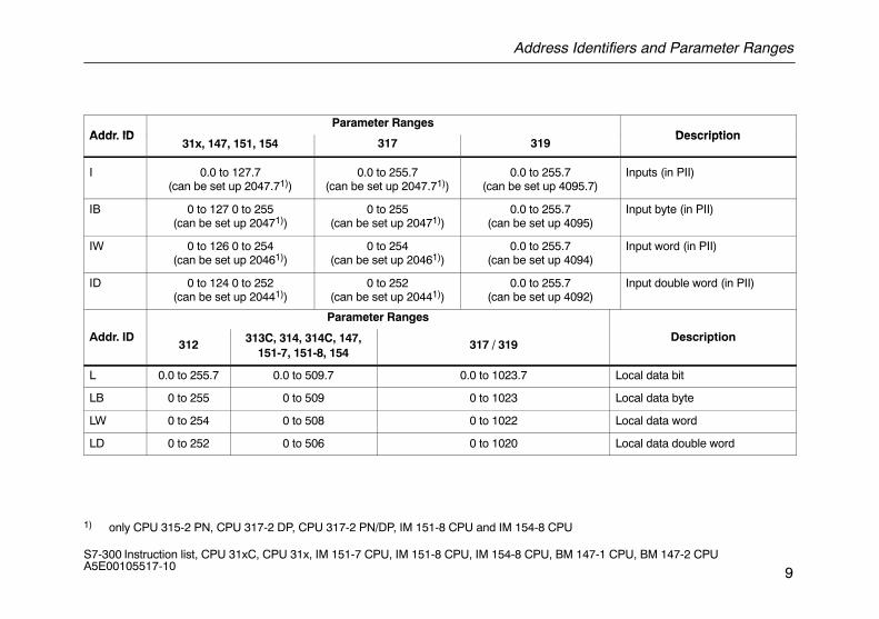
Addr IDParameter Ranges
DescriptionAddr. ID31x, 147, 151, 154 317 319
Description
I 0.0 to 127.7(can be set up 2047.71))
0.0 to 255.7(can be set up 2047.71))
0.0 to 255.7(can be set up 4095.7)
Inputs (in PII)
IB 0 to 127 0 to 255(can be set up 20471))
0 to 255(can be set up 20471))
0.0 to 255.7(can be set up 4095)
Input byte (in PII)
IW 0 to 126 0 to 254(can be set up 20461))
0 to 254(can be set up 20461))
0.0 to 255.7(can be set up 4094)
Input word (in PII)
ID 0 to 124 0 to 252(can be set up 20441))
0 to 252(can be set up 20441))
0.0 to 255.7(can be set up 4092)
Input double word (in PII)
Parameter Ranges
Addr. ID312 313C, 314, 314C, 147,
151-7, 151-8, 154317 / 319
Description
L 0.0 to 255.7 0.0 to 509.7 0.0 to 1023.7 Local data bit
LB 0 to 255 0 to 509 0 to 1023 Local data byte
LW 0 to 254 0 to 508 0 to 1022 Local data word
LD 0 to 252 0 to 506 0 to 1020 Local data double word
1) only CPU 315-2 PN, CPU 317-2 DP, CPU 317-2 PN/DP, IM 151-8 CPU and IM 154-8 CPU
Address Identifiers and Parameter Ranges
10S7-300 Instruction list, CPU 31xC, CPU 31x, IM 151-7 CPU, IM 151-8 CPU, IM 154-8 CPU, BM 147-1 CPU, BM 147-2 CPU A5E00105517-10
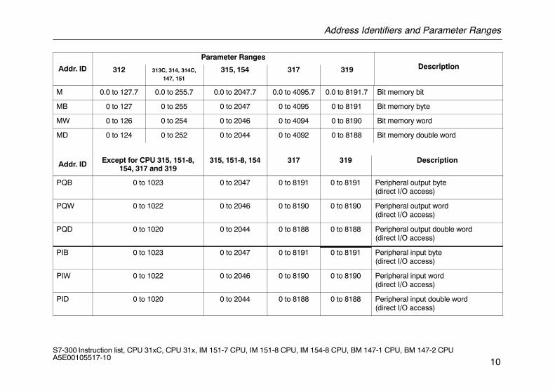
Parameter RangesD i tiAddr. ID 312 313C, 314, 314C,
147, 151315, 154 317 319 Description
M 0.0 to 127.7 0.0 to 255.7 0.0 to 2047.7 0.0 to 4095.7 0.0 to 8191.7 Bit memory bit
MB 0 to 127 0 to 255 0 to 2047 0 to 4095 0 to 8191 Bit memory byte
MW 0 to 126 0 to 254 0 to 2046 0 to 4094 0 to 8190 Bit memory word
MD 0 to 124 0 to 252 0 to 2044 0 to 4092 0 to 8188 Bit memory double word
Addr. ID Except for CPU 315, 151-8,154, 317 and 319
315, 151-8, 154 317 319 Description
PQB 0 to 1023 0 to 2047 0 to 8191 0 to 8191 Peripheral output byte (direct I/O access)
PQW 0 to 1022 0 to 2046 0 to 8190 0 to 8190 Peripheral output word (direct I/O access)
PQD 0 to 1020 0 to 2044 0 to 8188 0 to 8188 Peripheral output double word (direct I/O access)
PIB 0 to 1023 0 to 2047 0 to 8191 0 to 8191 Peripheral input byte(direct I/O access)
PIW 0 to 1022 0 to 2046 0 to 8190 0 to 8190 Peripheral input word (direct I/O access)
PID 0 to 1020 0 to 2044 0 to 8188 0 to 8188 Peripheral input double word (direct I/O access)
Address Identifiers and Parameter Ranges
11S7-300 Instruction list, CPU 31xC, CPU 31x, IM 151-7 CPU, IM 151-8 CPU, IM 154-8 CPU, BM 147-1 CPU, BM 147-2 CPU A5E00105517-10
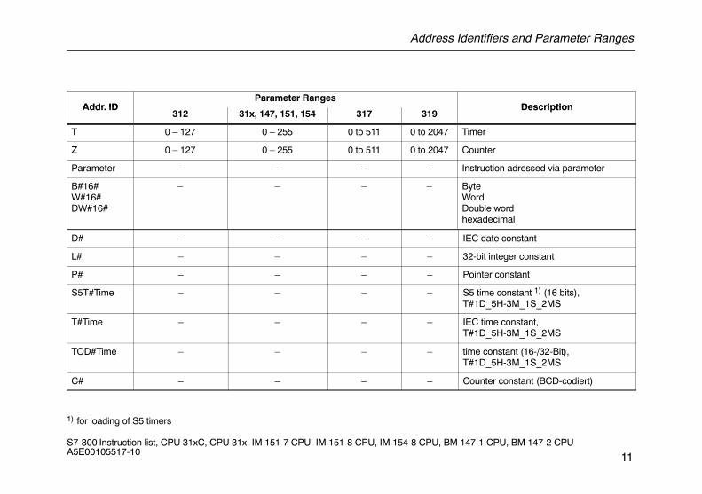
Addr IDParameter Ranges
DescriptionAddr. ID312 31x, 147, 151, 154 317 319
Description
T 0 – 127 0 – 255 0 to 511 0 to 2047 Timer
Z 0 – 127 0 – 255 0 to 511 0 to 2047 Counter
Parameter – – – – Instruction adressed via parameter
B#16#W#16#DW#16#
– – – – ByteWordDouble wordhexadecimal
D# – – – – IEC date constant
L# – – – – 32-bit integer constant
P# – – – – Pointer constant
S5T#Time – – – – S5 time constant 1) (16 bits),T#1D_5H-3M_1S_2MS
T#Time – – – – IEC time constant,T#1D_5H-3M_1S_2MS
TOD#Time – – – – time constant (16-/32-Bit),T#1D_5H-3M_1S_2MS
C# – – – – Counter constant (BCD-codiert)
1) for loading of S5 timers
Address Identifiers and Parameter Ranges
12S7-300 Instruction list, CPU 31xC, CPU 31x, IM 151-7 CPU, IM 151-8 CPU, IM 154-8 CPU, BM 147-1 CPU, BM 147-2 CPU A5E00105517-10
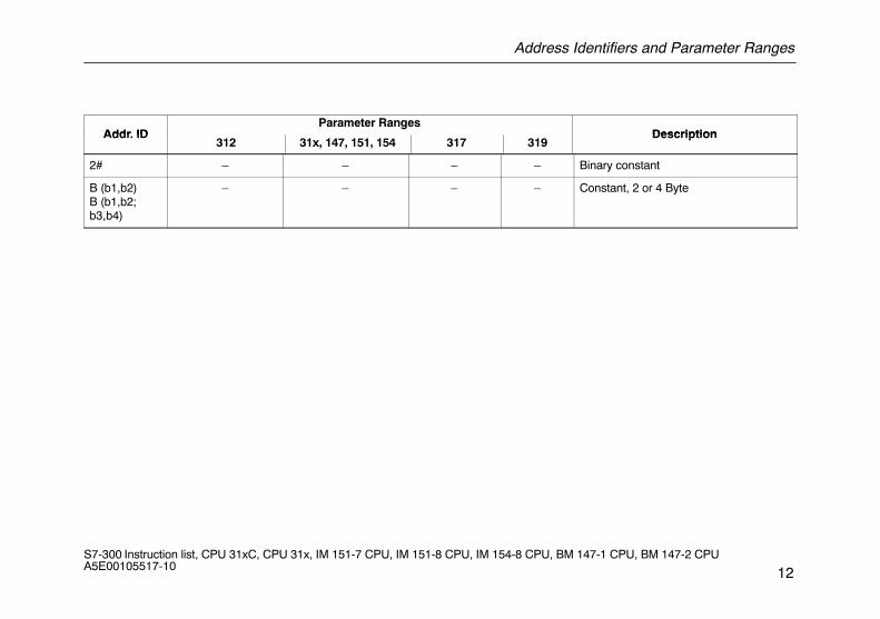
Addr IDParameter Ranges
DescriptionAddr. ID312 31x, 147, 151, 154 317 319
Description
2# – – – – Binary constant
B (b1,b2) B (b1,b2;b3,b4)
– – – – Constant, 2 or 4 Byte
Abbreviations and Mnemonics
13S7-300 Instruction list, CPU 31xC, CPU 31x, IM 151-7 CPU, IM 151-8 CPU, IM 154-8 CPU, BM 147-1 CPU, BM 147-2 CPU A5E00105517-10
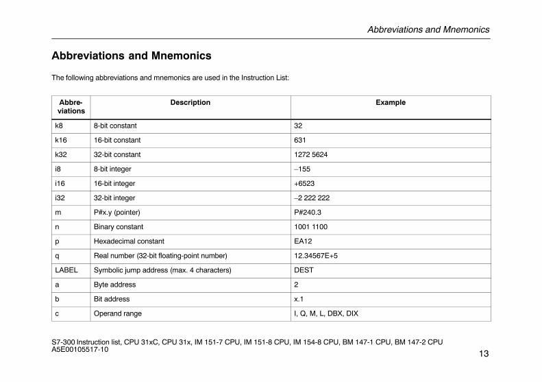
Abbreviations and Mnemonics
The following abbreviations and mnemonics are used in the Instruction List:
Abbre-viations
Description Example
k8 8-bit constant 32
k16 16-bit constant 631
k32 32-bit constant 1272 5624
i8 8-bit integer –155
i16 16-bit integer +6523
i32 32-bit integer –2 222 222
m P#x.y (pointer) P#240.3
n Binary constant 1001 1100
p Hexadecimal constant EA12
q Real number (32-bit floating-point number) 12.34567E+5
LABEL Symbolic jump address (max. 4 characters) DEST
a Byte address 2
b Bit address x.1
c Operand range I, Q, M, L, DBX, DIX
Abbreviations and Mnemonics
14S7-300 Instruction list, CPU 31xC, CPU 31x, IM 151-7 CPU, IM 151-8 CPU, IM 154-8 CPU, BM 147-1 CPU, BM 147-2 CPU A5E00105517-10
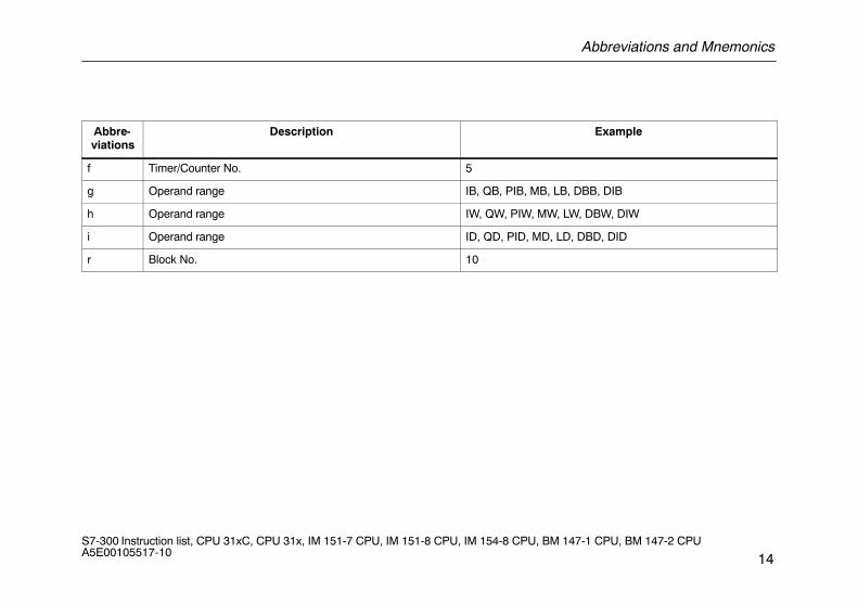
Abbre-viations
Description Example
f Timer/Counter No. 5
g Operand range IB, QB, PIB, MB, LB, DBB, DIB
h Operand range IW, QW, PIW, MW, LW, DBW, DIW
i Operand range ID, QD, PID, MD, LD, DBD, DID
r Block No. 10
Registers
15S7-300 Instruction list, CPU 31xC, CPU 31x, IM 151-7 CPU, IM 151-8 CPU, IM 154-8 CPU, BM 147-1 CPU, BM 147-2 CPU A5E00105517-10
Registers
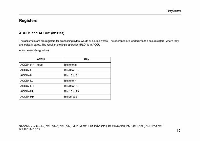
ACCU1 and ACCU2 (32 Bits)
The accumulators are registers for processing bytes, words or double words. The operands are loaded into the accumulators, where theyare logically gated. The result of the logic operation (RLO) is in ACCU1.
Accumulator designations:
ACCU Bits
ACCUx (x = 1 to 2) Bits 0 to 31
ACCUx-L Bits 0 to 15
ACCUx-H Bits 16 to 31
ACCUx-LL Bits 0 to 7
ACCUx-LH Bits 8 to 15
ACCUx-HL Bits 16 to 23
ACCUx-HH Bits 24 to 31
Registers
16S7-300 Instruction list, CPU 31xC, CPU 31x, IM 151-7 CPU, IM 151-8 CPU, IM 154-8 CPU, BM 147-1 CPU, BM 147-2 CPU A5E00105517-10
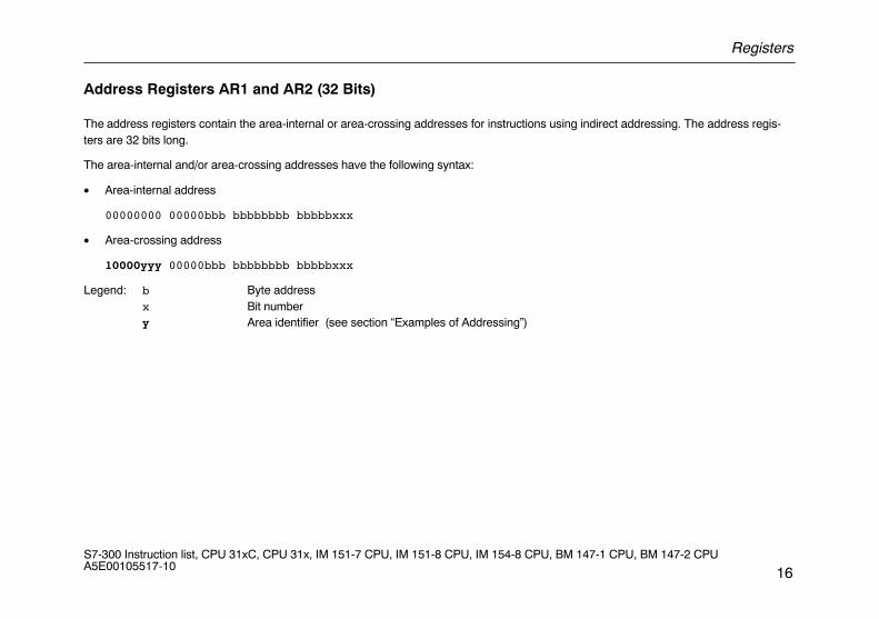
Address Registers AR1 and AR2 (32 Bits)
The address registers contain the area-internal or area-crossing addresses for instructions using indirect addressing. The address regis-ters are 32 bits long.
The area-internal and/or area-crossing addresses have the following syntax:
• Area-internal address
00000000 00000bbb bbbbbbbb bbbbbxxx
• Area-crossing address
10000yyy 00000bbb bbbbbbbb bbbbbxxx
Legend: b Byte addressx Bit numbery Area identifier (see section “Examples of Addressing”)
Registers
17S7-300 Instruction list, CPU 31xC, CPU 31x, IM 151-7 CPU, IM 151-8 CPU, IM 154-8 CPU, BM 147-1 CPU, BM 147-2 CPU A5E00105517-10
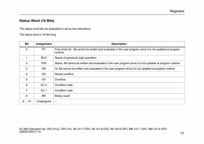
Status Word (16 Bits)
The status word bits are evaluated or set by the instructions.
The status word is 16 bits long.
Bit Assignment Description
0 FC First check bit , Bit cannot be written and evaluated in the user program since it is not updated at programruntime
1 RLO Result of (previous) logic operation
2 STA Status, Bit cannot be written and evaluated in the user program since it is not updated at program runtime
3 OR Or, Bit cannot be written and evaluated in the user program since it is not updated at program runtime
4 OS Stored overflow
5 OV Overflow
6 CC 0 Condition code
7 CC 1 Condition code
8 BR Binary result
9 ... 15 Unassigned –
Examples of Addressing
18S7-300 Instruction list, CPU 31xC, CPU 31x, IM 151-7 CPU, IM 151-8 CPU, IM 154-8 CPU, BM 147-1 CPU, BM 147-2 CPU A5E00105517-10
Examples of Addressing
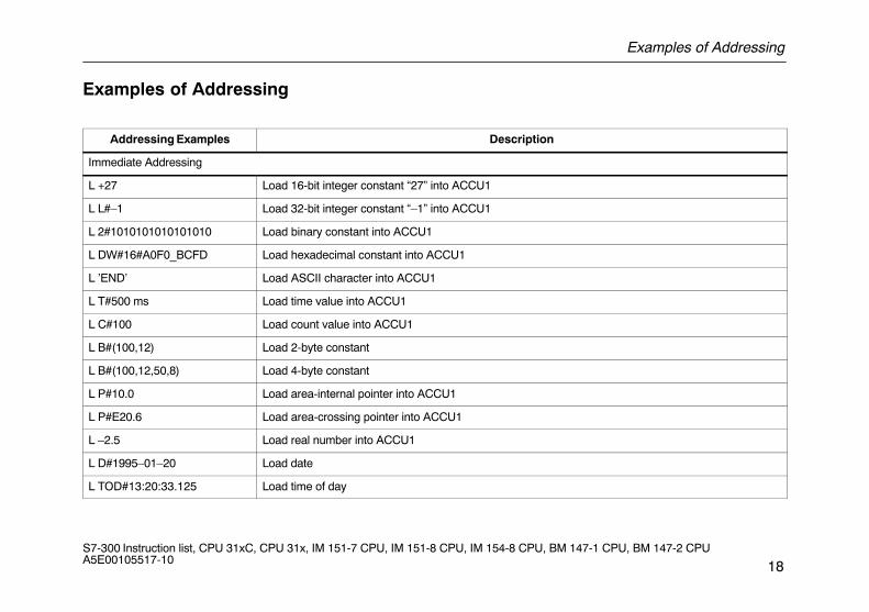
Addressing Examples Description
Immediate Addressing
L +27 Load 16-bit integer constant “27” into ACCU1
L L#–1 Load 32-bit integer constant “–1” into ACCU1
L 2#1010101010101010 Load binary constant into ACCU1
L DW#16#A0F0_BCFD Load hexadecimal constant into ACCU1
L ’END’ Load ASCII character into ACCU1
L T#500 ms Load time value into ACCU1
L C#100 Load count value into ACCU1
L B#(100,12) Load 2-byte constant
L B#(100,12,50,8) Load 4-byte constant
L P#10.0 Load area-internal pointer into ACCU1
L P#E20.6 Load area-crossing pointer into ACCU1
L –2.5 Load real number into ACCU1
L D#1995–01–20 Load date
L TOD#13:20:33.125 Load time of day
Examples of Addressing
19S7-300 Instruction list, CPU 31xC, CPU 31x, IM 151-7 CPU, IM 151-8 CPU, IM 154-8 CPU, BM 147-1 CPU, BM 147-2 CPU A5E00105517-10
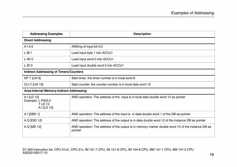
Addressing Examples Description
Direct Addressing
A I 0.0 ANDing of input bit 0.0
L IB 1 Load input byte 1 into ACCU1
L IW 0 Load input word 0 into ACCU1
L ID 0 Load input double word 0 into ACCU1
Indirect Addressing of Timers/Counters
SP T [LW 8] Start timer; the timer number is in local word 8
CU C [LW 10] Start counter; the counter number is in local data word 10
Area-Internal Memory-Indirect Addressing
A I [LD 12]Example: L P#22.2
T LD 12A I [LD 12]
AND operation: The address of the input is in local data double word 12 as pointer
A I [DBD 1] AND operation: The address of the input is in data double word 1 of the DB as pointer
A Q [DID 12] AND operation: The address of the output is in data double word 12 of the instance DB as pointer
A Q [MD 12] AND operation: The address of the output is in memory marker double word 12 of the instance DB aspointer
Examples of Addressing
20S7-300 Instruction list, CPU 31xC, CPU 31x, IM 151-7 CPU, IM 151-8 CPU, IM 154-8 CPU, BM 147-1 CPU, BM 147-2 CPU A5E00105517-10
Addressing Examples Description
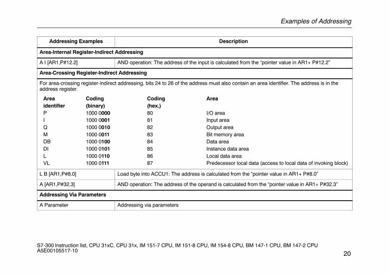
Area-Internal Register-Indirect Addressing
A I [AR1,P#12.2] AND operation: The address of the input is calculated from the “pointer value in AR1+ P#12.2”
Area-Crossing Register-Indirect Addressing
For area-crossing register-indirect addressing, bits 24 to 26 of the address must also contain an area identifier. The address is in theaddress register.
Area Coding Coding Areaidentifier (binary) (hex.)P 1000 0000 80 I/O areaI 1000 0001 81 Input areaQ 1000 0010 82 Output areaM 1000 0011 83 Bit memory areaDB 1000 0100 84 Data areaDI 1000 0101 85 Instance data areaL 1000 0110 86 Local data areaVL 1000 0111 87 Predecessor local data (access to local data of invoking block)
L B [AR1,P#8.0] Load byte into ACCU1: The address is calculated from the “pointer value in AR1+ P#8.0”
A [AR1,P#32.3] AND operation: The address of the operand is calculated from the “pointer value in AR1+ P#32.3”
Addressing Via Parameters
A Parameter Addressing via parameters
Examples of how to calculate the pointer
21S7-300 Instruction list, CPU 31xC, CPU 31x, IM 151-7 CPU, IM 151-8 CPU, IM 154-8 CPU, BM 147-1 CPU, BM 147-2 CPU A5E00105517-10
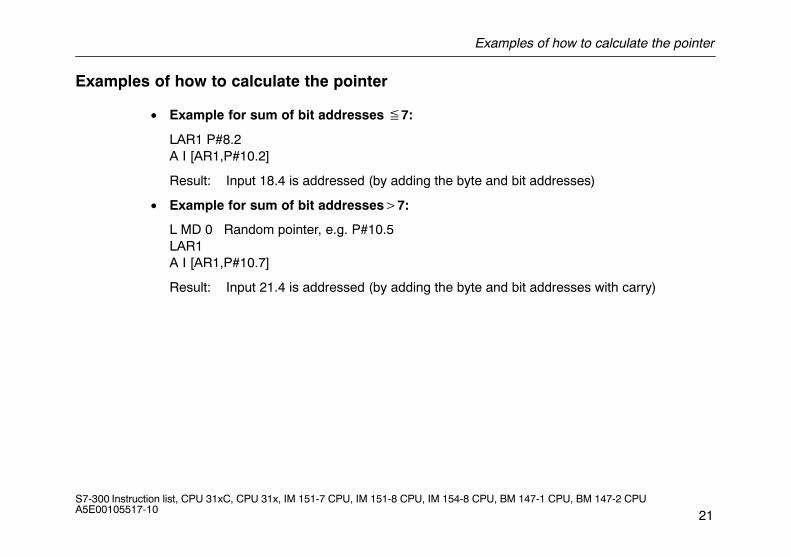
Examples of how to calculate the pointer
• Example for sum of bit addresses �7:
LAR1 P#8.2A I [AR1,P#10.2]
Result: Input 18.4 is addressed (by adding the byte and bit addresses)
• Example for sum of bit addresses�7:
L MD 0 Random pointer, e.g. P#10.5LAR1A I [AR1,P#10.7]
Result: Input 21.4 is addressed (by adding the byte and bit addresses with carry)
Execution Times with Indirect Addressing
22S7-300 Instruction list, CPU 31xC, CPU 31x, IM 151-7 CPU, IM 151-8 CPU, IM 154-8 CPU, BM 147-1 CPU, BM 147-2 CPU A5E00105517-10
Execution Times with Indirect Addressing
You must calculate the execution times when using indirect addressing. This chapter shows you how.
Two-Part Statement
A statement with indirectly addressed instructions consists of two parts:
Part 1: Load the address of the instruction
Part 2: Execute the instruction
In other words, you must calculate the execution time of a statement with indirectly addressed instructions from these two parts.
Execution Times with Indirect Addressing
23S7-300 Instruction list, CPU 31xC, CPU 31x, IM 151-7 CPU, IM 151-8 CPU, IM 154-8 CPU, BM 147-1 CPU, BM 147-2 CPU A5E00105517-10
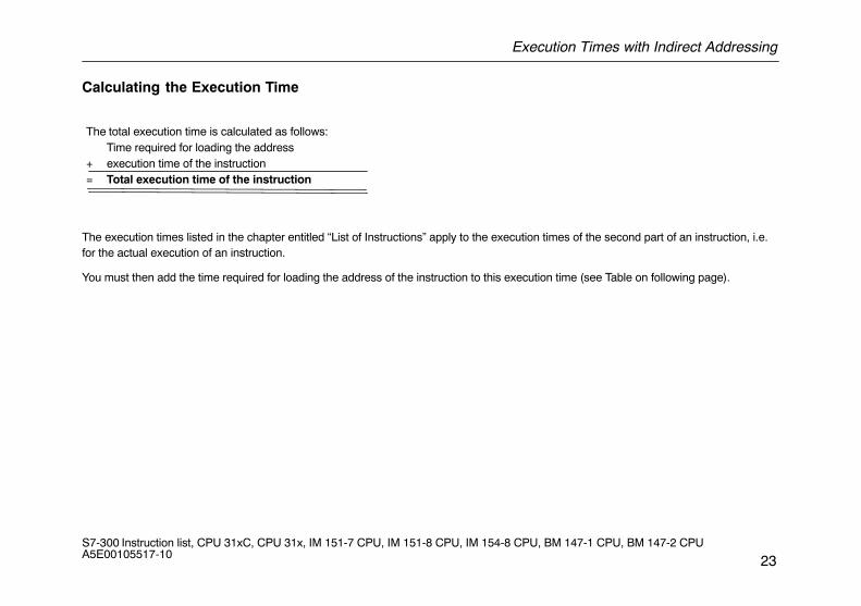
Calculating the Execution Time
The total execution time is calculated as follows:Time required for loading the address
+ execution time of the instruction= Total execution time of the instruction
The execution times listed in the chapter entitled “List of Instructions” apply to the execution times of the second part of an instruction, i.e.for the actual execution of an instruction.
You must then add the time required for loading the address of the instruction to this execution time (see Table on following page).
Execution Times with Indirect Addressing
24S7-300 Instruction list, CPU 31xC, CPU 31x, IM 151-7 CPU, IM 151-8 CPU, IM 154-8 CPU, BM 147-1 CPU, BM 147-2 CPU A5E00105517-10
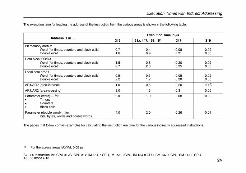
The execution time for loading the address of the instruction from the various areas is shown in the following table.
Address is in Execution Time in �s
Address is in ...312 31x, 147, 151, 154 317 319
Bit memory area MWord (for times, counters and block calls)Double word
0.71.6
0.40.9
0.080.21
0.020.05
Data block DB/DXWord (for times, counters and block calls)Double word
1.53.7
0.82.0
0.200.25
0.020.05
Local data area LWord (for times, counters and block calls)Double word
0.92.2
0.51.2
0.080.20
0.020.05
AR1/AR2 (area-internal) 1.0 0.5 0.20 0.021)
AR1/AR2 (area-crossing) 3.0 1.6 0.31 0.05
Parameter (word) ... for:• Timers• Counters• Block calls
2.0 1.0 0.08 0.02
Parameter (double word) ... forBits, bytes, words and double words
4.0 2.0 0.26 0.01
The pages that follow contain examples for calculating the instruction run time for the various indirectly addressed instructions.
1) For the adress areas I/Q/M/L 0.05 �s
Calculating the Execution Time Using a CPU 314C-2 DP as an Example
25S7-300 Instruction list, CPU 31xC, CPU 31x, IM 151-7 CPU, IM 151-8 CPU, IM 154-8 CPU, BM 147-1 CPU, BM 147-2 CPU A5E00105517-10
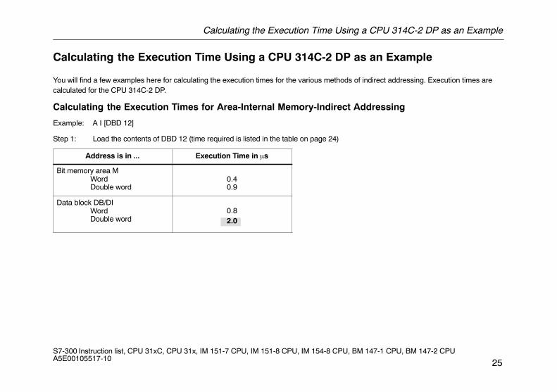
Calculating the Execution Time Using a CPU 314C-2 DP as an Example
You will find a few examples here for calculating the execution times for the various methods of indirect addressing. Execution times arecalculated for the CPU 314C-2 DP.
Calculating the Execution Times for Area-Internal Memory-Indirect Addressing
Example: A I [DBD 12]
Step 1: Load the contents of DBD 12 (time required is listed in the table on page 24)
Address is in ... Execution Time in �s
Bit memory area MWordDouble word
0.40.9
Data block DB/DIWordDouble word 2.0
0.8
Calculating the Execution Time Using a CPU 314C-2 DP as an Example
26S7-300 Instruction list, CPU 31xC, CPU 31x, IM 151-7 CPU, IM 151-8 CPU, IM 154-8 CPU, BM 147-1 CPU, BM 147-2 CPU A5E00105517-10
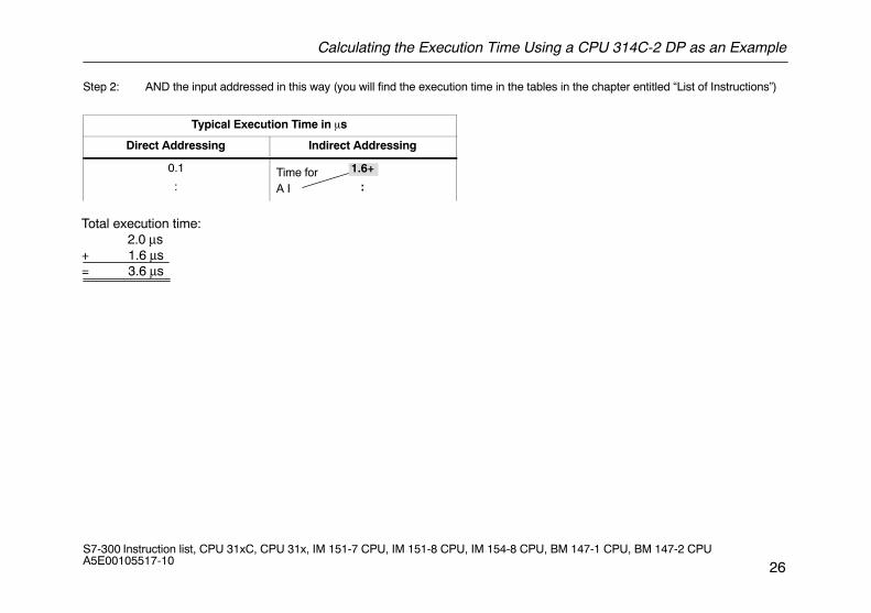
Step 2: AND the input addressed in this way (you will find the execution time in the tables in the chapter entitled “List of Instructions”)
Typical Execution Time in �s
Direct Addressing Indirect Addressing
0.1
:
1.6+
:Time for A I
Total execution time: 2.0 μs+ 1.6 μs= 3.6 μs
Calculating the Execution Time Using a CPU 314C-2 DP as an Example
27S7-300 Instruction list, CPU 31xC, CPU 31x, IM 151-7 CPU, IM 151-8 CPU, IM 154-8 CPU, BM 147-1 CPU, BM 147-2 CPU A5E00105517-10
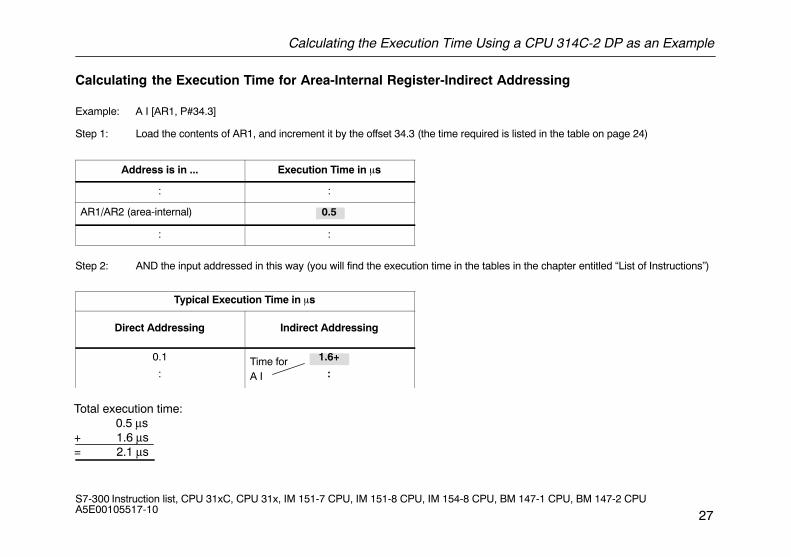
Calculating the Execution Time for Area-Internal Register-Indirect Addressing
Example: A I [AR1, P#34.3]
Step 1: Load the contents of AR1, and increment it by the offset 34.3 (the time required is listed in the table on page 24)
Address is in ... Execution Time in �s
: :
AR1/AR2 (area-internal) 0.5
: :
Step 2: AND the input addressed in this way (you will find the execution time in the tables in the chapter entitled “List of Instructions”)
Typical Execution Time in �s
Direct Addressing Indirect Addressing
0.1
:
1.6+
:Time for A I
Total execution time: 0.5 μs+ 1.6 μs= 2.1 μs
Calculating the Execution Time Using a CPU 314C-2 DP as an Example
28S7-300 Instruction list, CPU 31xC, CPU 31x, IM 151-7 CPU, IM 151-8 CPU, IM 154-8 CPU, BM 147-1 CPU, BM 147-2 CPU A5E00105517-10
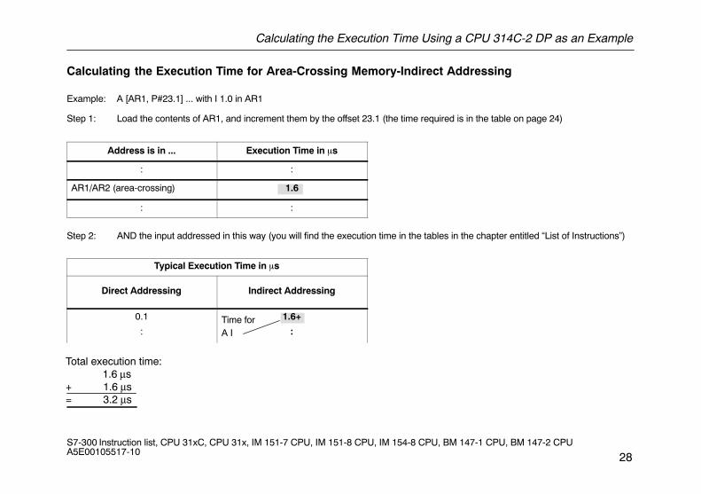
Calculating the Execution Time for Area-Crossing Memory-Indirect Addressing
Example: A [AR1, P#23.1] ... with I 1.0 in AR1
Step 1: Load the contents of AR1, and increment them by the offset 23.1 (the time required is in the table on page 24)
Address is in ... Execution Time in �s
: :
AR1/AR2 (area-crossing) 1.6
: :
Step 2: AND the input addressed in this way (you will find the execution time in the tables in the chapter entitled “List of Instructions”)
Typical Execution Time in �s
Direct Addressing Indirect Addressing
0.1
:
1.6+
:Time for A I
Total execution time: 1.6 μs+ 1.6 μs= 3.2 μs
Calculating the Execution Time Using a CPU 314C-2 DP as an Example
29S7-300 Instruction list, CPU 31xC, CPU 31x, IM 151-7 CPU, IM 151-8 CPU, IM 154-8 CPU, BM 147-1 CPU, BM 147-2 CPU A5E00105517-10
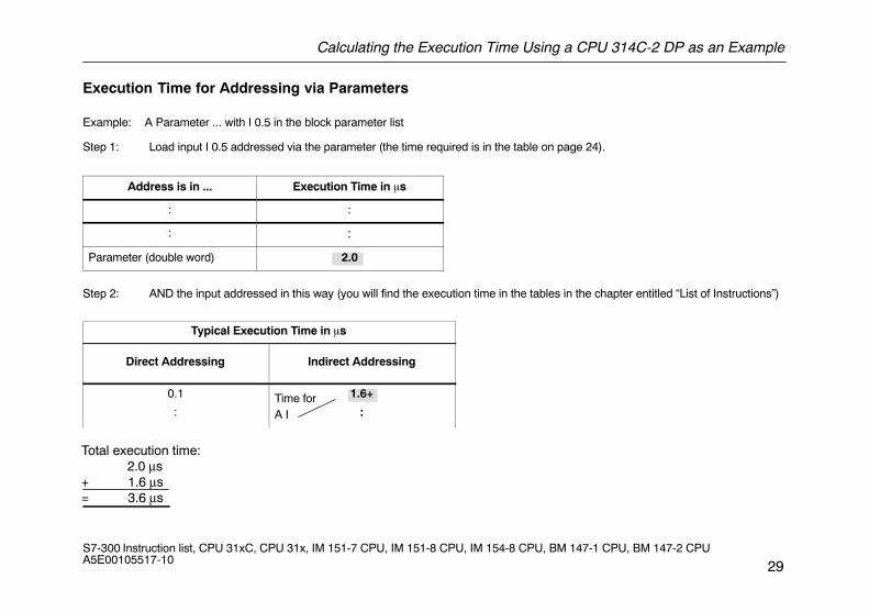
Execution Time for Addressing via Parameters
Example: A Parameter ... with I 0.5 in the block parameter list
Step 1: Load input I 0.5 addressed via the parameter (the time required is in the table on page 24).
Address is in ... Execution Time in �s
: :
: :
Parameter (double word) 2.0
Step 2: AND the input addressed in this way (you will find the execution time in the tables in the chapter entitled “List of Instructions”)
Typical Execution Time in �s
Direct Addressing Indirect Addressing
0.1
:
1.6+
:Time for A I
Total execution time: 2.0 μs+ 1.6 μs= 3.6 μs
List of Instructions
30S7-300 Instruction list, CPU 31xC, CPU 31x, IM 151-7 CPU, IM 151-8 CPU, IM 154-8 CPU, BM 147-1 CPU, BM 147-2 CPU A5E00105517-10
List of Instructions
This chapter contains the complete list of S7-300 instructions. The descriptions have been kept as concise as possible. You will find a de-tailed functional description in the various STEP 7 reference manuals.Please note that, in the case of indirect addressing (examples see page 19), you must add the time required for loading the address of theparticular instruction to the execution times listed (see page 24).
Bit Logic Instructions
31S7-300 Instruction list, CPU 31xC, CPU 31x, IM 151-7 CPU, IM 151-8 CPU, IM 154-8 CPU, BM 147-1 CPU, BM 147-2 CPU A5E00105517-10
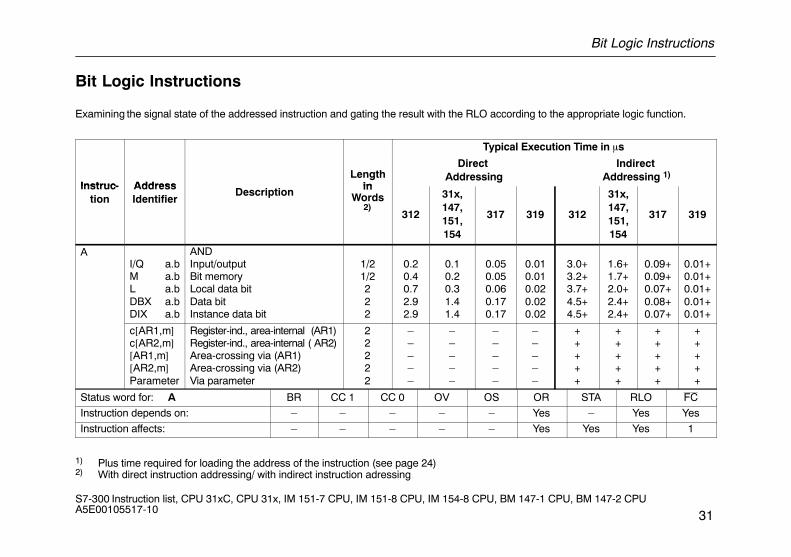
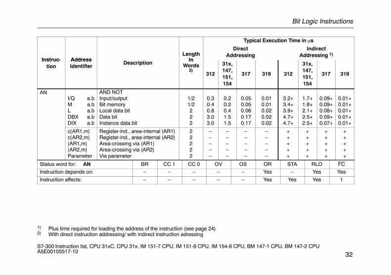
Bit Logic Instructions
Examining the signal state of the addressed instruction and gating the result with the RLO according to the appropriate logic function.
Typical Execution Time in �s
Instruc- AddressLength
in
Direct Addressing
Indirect Addressing 1)
Instruc-tion
AddressIdentifier
Description inWords
2)312
31x,147,151,154
317 319 312
31x,147,151,154
317 319
AI/Q a.bM a.bL a.bDBX a.bDIX a.b
ANDInput/outputBit memoryLocal data bitData bitInstance data bit
1/21/2222
0.20.40.72.92.9
0.10.20.31.41.4
0.050.050.060.170.17
0.010.010.020.020.02
3.0+3.2+3.7+4.5+4.5+
1.6+1.7+2.0+2.4+2.4+
0.09+0.09+0.07+0.08+0.07+
0.01+0.01+0.01+0.01+0.01+
c[AR1,m]c[AR2,m][AR1,m][AR2,m]Parameter
Register-ind., area-internal (AR1)Register-ind., area-internal ( AR2)Area-crossing via (AR1)Area-crossing via (AR2)Via parameter
22222
–––––
–––––
–––––
–––––
+++++
+++++
+++++
+++++
Status word for: A BR CC 1 CC 0 OV OS OR STA RLO FC
Instruction depends on: – – – – – Yes – Yes Yes
Instruction affects: – – – – – Yes Yes Yes 1
1) Plus time required for loading the address of the instruction (see page 24)2) With direct instruction addressing/ with indirect instruction adressing
Bit Logic Instructions
32S7-300 Instruction list, CPU 31xC, CPU 31x, IM 151-7 CPU, IM 151-8 CPU, IM 154-8 CPU, BM 147-1 CPU, BM 147-2 CPU A5E00105517-10
Typical Execution Time in �s
Instruc- AddressLength
in
DirectAddressing
IndirectAddressing 1)
Instruc-tion
AddressIdentifier
Description inWords
2)312
31x,147,151,154
317 319 312
31x,147,151,154
317 319
ANI/Q a.bM a.bL a.bDBX a.bDIX a.b
AND NOTInput/outputBit memoryLocal data bitData bitInstance data bit
1/21/2222
0.30.40.83.03.0
0.20.20.41.51.5
0.050.050.060.170.17
0.010.010.020.020.02
3.2+3.4+3.9+4.7+4.7+
1.7+1.8+2.1+2.5+2.5+
0.09+0.09+0.08+0.09+0.07+
0.01+0.01+0.01+0.01+0.01+
c[AR1,m]c[AR2,m][AR1,m][AR2,m]Parameter
Register-ind., area-internal (AR1)Register-ind., area-internal (AR2)Area-crossing via (AR1)Area-crossing via (AR2)Via parameter
22222
–––––
–––––
–––––
–––––
+++++
+++++
+++++
+++++
Status word for: AN BR CC 1 CC 0 OV OS OR STA RLO FC
Instruction depends on: – – – – – Yes – Yes Yes
Instruction affects: – – – – – Yes Yes Yes 1
1) Plus time required for loading the address of the instruction (see page 24)2) With direct instruction addressing/ with indirect instruction adressing
Bit Logic Instructions
33S7-300 Instruction list, CPU 31xC, CPU 31x, IM 151-7 CPU, IM 151-8 CPU, IM 154-8 CPU, BM 147-1 CPU, BM 147-2 CPU A5E00105517-10
Typical Execution Time in �s
Instruc- AddressLength
in
DirectAddressing
IndirectAddressing 1)
Instruc-tion
AddressIdentifier Description
inWords
2) 312
31x,147,151,154
317 319 312
31x,147,151,154
317 319
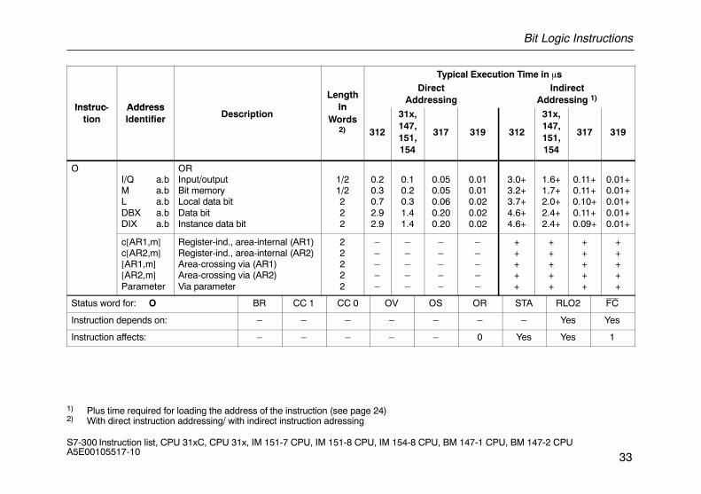
OI/Q a.bM a.bL a.bDBX a.bDIX a.b
ORInput/outputBit memoryLocal data bitData bitInstance data bit
1/21/2222
0.20.30.72.92.9
0.10.20.31.41.4
0.050.050.060.200.20
0.010.010.020.020.02
3.0+3.2+3.7+4.6+4.6+
1.6+1.7+2.0+2.4+2.4+
0.11+0.11+0.10+0.11+0.09+
0.01+0.01+0.01+0.01+0.01+
c[AR1,m]c[AR2,m][AR1,m][AR2,m]Parameter
Register-ind., area-internal (AR1)Register-ind., area-internal (AR2)Area-crossing via (AR1)Area-crossing via (AR2)Via parameter
22222
–––––
–––––
–––––
–––––
+++++
+++++
+++++
+++++
Status word for: O BR CC 1 CC 0 OV OS OR STA RLO2 FC
Instruction depends on: – – – – – – – Yes Yes
Instruction affects: – – – – – 0 Yes Yes 1
1) Plus time required for loading the address of the instruction (see page 24)2) With direct instruction addressing/ with indirect instruction adressing

Bit Logic Instructions
34S7-300 Instruction list, CPU 31xC, CPU 31x, IM 151-7 CPU, IM 151-8 CPU, IM 154-8 CPU, BM 147-1 CPU, BM 147-2 CPU A5E00105517-10
Typical Execution Time in �s
Instruc- AddressLength
in
DirectAddressing
IndirectAddressing 1)
Instruc-tion
AddressIdentifier Description
inWords
2) 312
31x,147,151,154
317 319 312
31x,147,151,154
317 319
ONI/Q a.bM a.bL a.bDBX a.bDIX a.b
OR NOTInput/outputBit memoryLocal data bitData bitInstance data bit
1/21/2222
0.30.40.83.03.0
0.20.20.41.51.5
0.050.050.060.200.20
0.010.010.020.020.02
3.2+3.5+3.9+4.7+4.7+
1.7+1.8+2.1+2.5+2.5+
0.11+0.11+0.10+0.11+0.09+
0.01+0.01+0.01+0.01+0.01+
c[AR1,m]c[AR2,m][AR1,m][AR2,m]Parameter
Register-ind., area-internal (AR1)Register-ind., area-internal (AR2)Area-crossing via (AR1)Area-crossing via (AR2)Via parameter
22222
–––––
–––––
–––––
–––––
+++++
+++++
+++++
+++++
Status word for: ON BR CC 1 CC 0 OV OS OR STA RLO FC
Instruction depends on: – – – – – – – Yes Yes
Instruction affects: – – – – – 0 Yes Yes 1
1) Plus time required for loading the address of the instruction (see page 24)2) With direct instruction addressing/ with indirect instruction adressing
Bit Logic Instructions
35S7-300 Instruction list, CPU 31xC, CPU 31x, IM 151-7 CPU, IM 151-8 CPU, IM 154-8 CPU, BM 147-1 CPU, BM 147-2 CPU A5E00105517-10
Typical Execution Time in �s
Instruc- AddressDescription
Lengthin
DirectAddressing
IndirectAddressing 1)
Instruction
AddressIdentifier Description
inWords
2)312
31x,147,151,154
317 319 312
31x,147,151,154
317 319
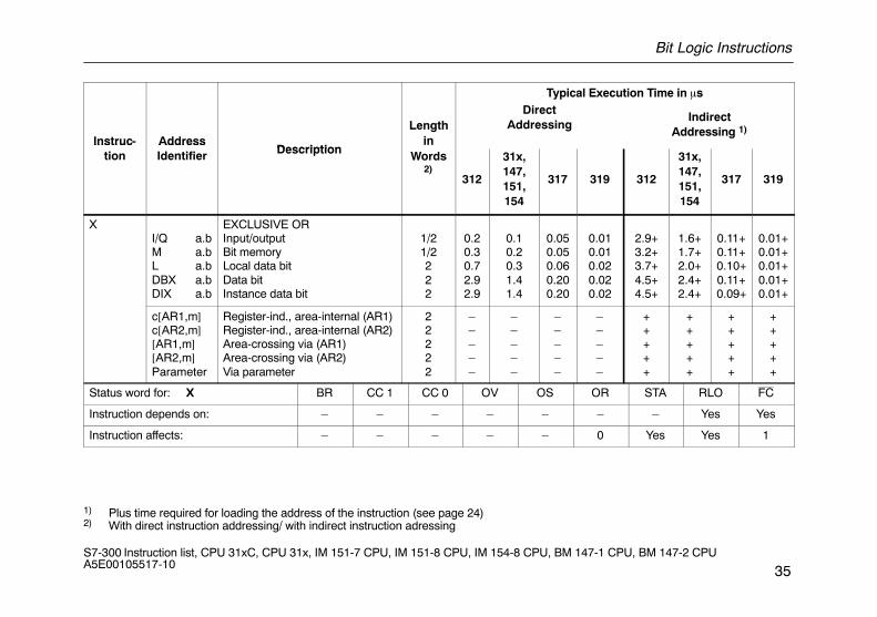
XI/Q a.bM a.bL a.bDBX a.bDIX a.b
EXCLUSIVE ORInput/outputBit memoryLocal data bitData bitInstance data bit
1/21/2222
0.20.30.72.92.9
0.10.20.31.41.4
0.050.050.060.200.20
0.010.010.020.020.02
2.9+3.2+3.7+4.5+4.5+
1.6+1.7+2.0+2.4+2.4+
0.11+0.11+0.10+0.11+0.09+
0.01+0.01+0.01+0.01+0.01+
c[AR1,m]c[AR2,m][AR1,m][AR2,m]Parameter
Register-ind., area-internal (AR1)Register-ind., area-internal (AR2)Area-crossing via (AR1)Area-crossing via (AR2)Via parameter
22222
–––––
–––––
–––––
–––––
+++++
+++++
+++++
+++++
Status word for: X BR CC 1 CC 0 OV OS OR STA RLO FC
Instruction depends on: – – – – – – – Yes Yes
Instruction affects: – – – – – 0 Yes Yes 1
1) Plus time required for loading the address of the instruction (see page 24)2) With direct instruction addressing/ with indirect instruction adressing
Bit Logic Instructions
36S7-300 Instruction list, CPU 31xC, CPU 31x, IM 151-7 CPU, IM 151-8 CPU, IM 154-8 CPU, BM 147-1 CPU, BM 147-2 CPU A5E00105517-10
Typical Execution Time in �s
Instruc- AddressLength
in
DirectAddressing
IndirectAddressing 1)
Instruc-tion
AddressIdentifier Description
inWords
2) 312
31x,147,151,154
317 319 312
31x,147,151,154
317 319
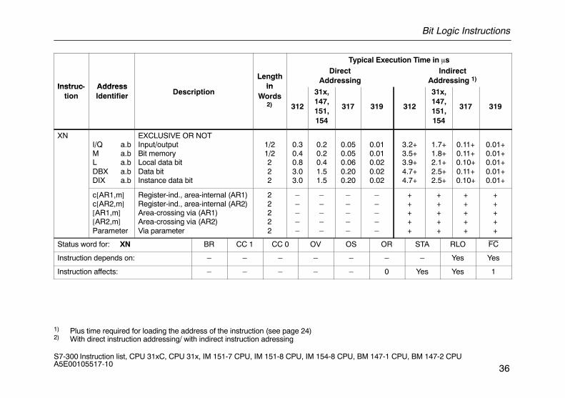
XNI/Q a.bM a.bL a.bDBX a.bDIX a.b
EXCLUSIVE OR NOTInput/outputBit memoryLocal data bitData bitInstance data bit
1/21/2222
0.30.40.83.03.0
0.20.20.41.51.5
0.050.050.060.200.20
0.010.010.020.020.02
3.2+3.5+3.9+4.7+4.7+
1.7+1.8+2.1+2.5+2.5+
0.11+0.11+0.10+0.11+0.10+
0.01+0.01+0.01+0.01+0.01+
c[AR1,m]c[AR2,m][AR1,m][AR2,m]Parameter
Register-ind., area-internal (AR1)Register-ind., area-internal (AR2)Area-crossing via (AR1)Area-crossing via (AR2)Via parameter
22222
–––––
–––––
–––––
–––––
+++++
+++++
+++++
+++++
Status word for: XN BR CC 1 CC 0 OV OS OR STA RLO FC
Instruction depends on: – – – – – – – Yes Yes
Instruction affects: – – – – – 0 Yes Yes 1
1) Plus time required for loading the address of the instruction (see page 24)2) With direct instruction addressing/ with indirect instruction adressing
Bit Logic Instructions with Parenthetical Expressions
37S7-300 Instruction list, CPU 31xC, CPU 31x, IM 151-7 CPU, IM 151-8 CPU, IM 154-8 CPU, BM 147-1 CPU, BM 147-2 CPU A5E00105517-10
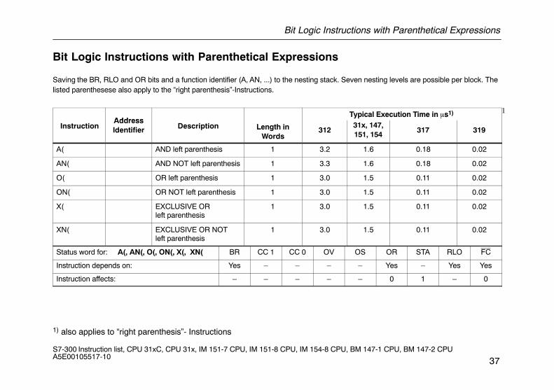
Bit Logic Instructions with Parenthetical Expressions
Saving the BR, RLO and OR bits and a function identifier (A, AN, ...) to the nesting stack. Seven nesting levels are possible per block. Thelisted parenthesese also apply to the “right parenthesis”-Instructions.
AddressTypical Execution Time in �s1) 1
InstructionAddressIdentifier Description Length in
Words312
31x, 147,151, 154
317 319
A( AND left parenthesis 1 3.2 1.6 0.18 0.02
AN( AND NOT left parenthesis 1 3.3 1.6 0.18 0.02
O( OR left parenthesis 1 3.0 1.5 0.11 0.02
ON( OR NOT left parenthesis 1 3.0 1.5 0.11 0.02
X( EXCLUSIVE ORleft parenthesis
1 3.0 1.5 0.11 0.02
XN( EXCLUSIVE OR NOTleft parenthesis
1 3.0 1.5 0.11 0.02
Status word for: A(, AN(, O(, ON(, X(, XN( BR CC 1 CC 0 OV OS OR STA RLO FC
Instruction depends on: Yes – – – – Yes – Yes Yes
Instruction affects: – – – – – 0 1 – 0
1) also applies to “right parenthesis”- Instructions
Bit Logic Instructions with Parenthetical Expressions
38S7-300 Instruction list, CPU 31xC, CPU 31x, IM 151-7 CPU, IM 151-8 CPU, IM 154-8 CPU, BM 147-1 CPU, BM 147-2 CPU A5E00105517-10
AddressTypical Execution Time in �s
InstructionAddressIdentifier Description Length in
Words312
31x, 147,151, 154
317 319
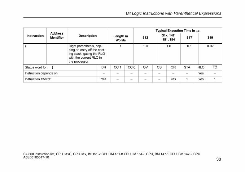
) Right parenthesis, pop-ping an entry off the nest-ing stack, gating the RLOwith the current RLO inthe processor
1 1.0 1.0 0.1 0.02
Status word for: ) BR CC 1 CC 0 OV OS OR STA RLO FC
Instruction depends on: – – – – – – – Yes –
Instruction affects: Yes – – – – Yes 1 Yes 1
ORing of AND Operations
39S7-300 Instruction list, CPU 31xC, CPU 31x, IM 151-7 CPU, IM 151-8 CPU, IM 154-8 CPU, BM 147-1 CPU, BM 147-2 CPU A5E00105517-10
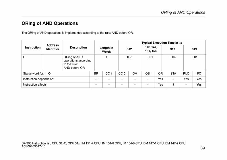
ORing of AND Operations
The ORing of AND operations is implemented according to the rule: AND before OR.
AddressTypical Execution Time in �s
InstructionAddressIdentifier Description Length in
Words312
31x, 147,151, 154
317 319
O ORing of ANDoperations accordingto the rule:AND before OR
1 0.2 0.1 0.04 0.01
Status word for: O BR CC 1 CC 0 OV OS OR STA RLO FC
Instruction depends on: – – – – – Yes – Yes Yes
Instruction affects: – – – – – Yes 1 – Yes
Logic Instructions with Timers and Counters
40S7-300 Instruction list, CPU 31xC, CPU 31x, IM 151-7 CPU, IM 151-8 CPU, IM 154-8 CPU, BM 147-1 CPU, BM 147-2 CPU A5E00105517-10
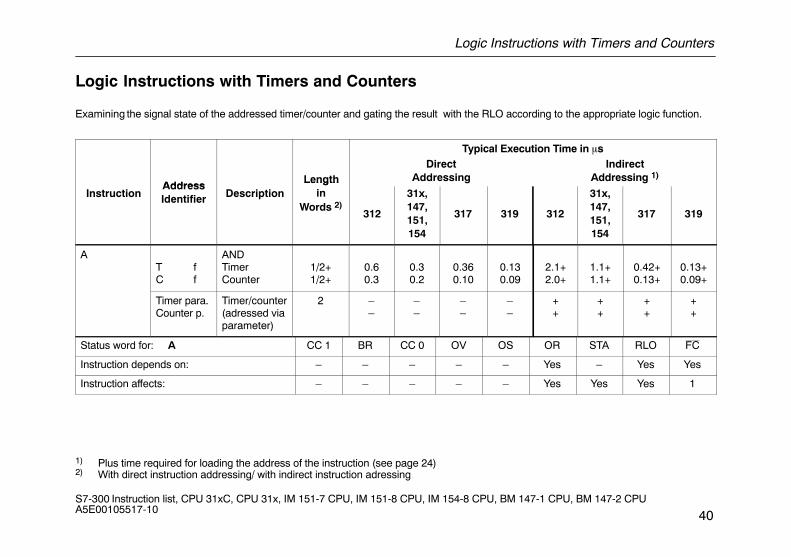
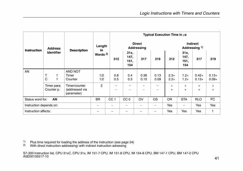
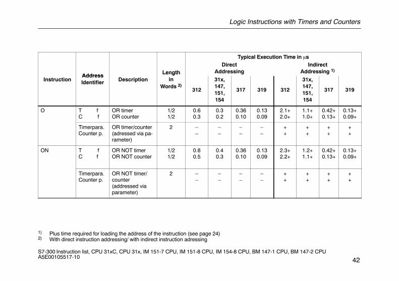
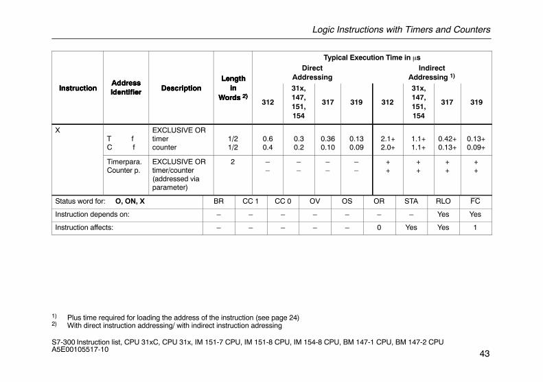
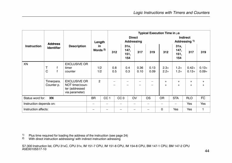
Logic Instructions with Timers and Counters
Examining the signal state of the addressed timer/counter and gating the result with the RLO according to the appropriate logic function.
Typical Execution Time in �s
AddressLength
DirectAddressing
IndirectAddressing 1)
InstructionAddressIdentifier Description
Lengthin
Words 2)312
31x,147,151,154
317 319 312
31x,147,151,154
317 319
AT fC f
ANDTimerCounter
1/2+1/2+
0.60.3
0.30.2
0.360.10
0.130.09
2.1+2.0+
1.1+1.1+
0.42+0.13+
0.13+0.09+
Timer para.Counter p.
Timer/counter(adressed viaparameter)
2 ––
––
––
––
++
++
++
++
Status word for: A CC 1 BR CC 0 OV OS OR STA RLO FC
Instruction depends on: – – – – – Yes – Yes Yes
Instruction affects: – – – – – Yes Yes Yes 1
1) Plus time required for loading the address of the instruction (see page 24)2) With direct instruction addressing/ with indirect instruction adressing
Logic Instructions with Timers and Counters
41S7-300 Instruction list, CPU 31xC, CPU 31x, IM 151-7 CPU, IM 151-8 CPU, IM 154-8 CPU, BM 147-1 CPU, BM 147-2 CPU A5E00105517-10
Typical Execution Time in �s
InstructionAddress
DescriptionLength
in
DirectAddressing
IndirectAddressing 1)
InstructionAddressIdentifier
Description inWords 2)
312
31x,147,151,154
317 319 312
31x,147,151,154
317 319
ANT fC f
AND NOTTimerCounter
1/21/2
0.80.5
0.40.3
0.360.10
0.130.09
2.3+2.2+
1.2+1.2+
0.42+0.13+
0.13+0.09+
Timer para.Counter p.
Timer/counter (addressed viaparameter)
2 ––
––
––
––
++
++
++
++
Status word for: AN BR CC 1 CC 0 OV OS OR STA RLO FC
Instruction depends on: – – – – – Yes – Yes Yes
Instruction affects: – – – – – Yes Yes Yes 1
1) Plus time required for loading the address of the instruction (see page 24)2) With direct instruction addressing/ with indirect instruction adressing
Logic Instructions with Timers and Counters
42S7-300 Instruction list, CPU 31xC, CPU 31x, IM 151-7 CPU, IM 151-8 CPU, IM 154-8 CPU, BM 147-1 CPU, BM 147-2 CPU A5E00105517-10
Typical Execution Time in �s
AddressLength
DirectAddressing
IndirectAddressing 1)
InstructionAddressIdentifier Description
Lengthin
Words 2)312
31x,147,151,154
317 319 312
31x,147,151,154
317 319
O T fC f
OR timerOR counter
1/21/2
0.60.3
0.30.2
0.360.10
0.130.09
2.1+2.0+
1.1+1.0+
0.42+0.13+
0.13+0.09+
Timerpara.Counter p.
OR timer/counter (adressed via pa-rameter)
2 ––
––
––
––
++
++
++
++
ON T fC f
OR NOT timerOR NOT counter
1/21/2
0.80.5
0.40.3
0.360.10
0.130.09
2.3+2.2+
1.2+1.1+
0.42+0.13+
0.13+0.09+
Timerpara.Counter p.
OR NOT timer/counter(addressed viaparameter)
2 ––
––
––
––
++
++
++
++
1) Plus time required for loading the address of the instruction (see page 24)2) With direct instruction addressing/ with indirect instruction adressing
Logic Instructions with Timers and Counters
43S7-300 Instruction list, CPU 31xC, CPU 31x, IM 151-7 CPU, IM 151-8 CPU, IM 154-8 CPU, BM 147-1 CPU, BM 147-2 CPU A5E00105517-10
Instruction
Typical Execution Time in �s
Lengthin
Words 2)Description
AddressIdentifierInstruction
IndirectAddressing 1)
DirectAddressingLength
inWords 2)
DescriptionAddressIdentifierInstruction
319317
31x,147,151,154
312319317
31x,147,151,154
312
Lengthin
Words 2)Description
AddressIdentifier
XT fC f
EXCLUSIVE ORtimercounter
1/21/2
0.60.4
0.30.2
0.360.10
0.130.09
2.1+2.0+
1.1+1.1+
0.42+0.13+
0.13+0.09+
Timerpara.Counter p.
EXCLUSIVE ORtimer/counter (addressed viaparameter)
2 ––
––
––
––
++
++
++
++
Status word for: O, ON, X BR CC 1 CC 0 OV OS OR STA RLO FC
Instruction depends on: – – – – – – – Yes Yes
Instruction affects: – – – – – 0 Yes Yes 1
1) Plus time required for loading the address of the instruction (see page 24)2) With direct instruction addressing/ with indirect instruction adressing
Logic Instructions with Timers and Counters
44S7-300 Instruction list, CPU 31xC, CPU 31x, IM 151-7 CPU, IM 151-8 CPU, IM 154-8 CPU, BM 147-1 CPU, BM 147-2 CPU A5E00105517-10
Typical Execution Time in �s
AddressLength
DirectAddressing
IndirectAddressing 1)
InstructionAddressIdentifier Description
Lengthin
Words 2)312
31x,147,151,154
317 319 312
31x,147,151,154
317 319
XNT fC f
EXCLUSIVE ORtimercounter
1/21/2
0.80.5
0.40.3
0.360.10
0.130.09
2.3+2.2+
1.2+1.2+
0.42+0.13+
0.13+0.09+
Timerpara.Counter p.
EXCLUSIVE ORNOT timer/coun-ter (addressedvia parameter)
2 ––
––
––
––
++
++
++
++
Status word for: XN BR CC 1 CC 0 OV OS OR STA RLO FC
Instruction depends on: – – – – – – – Yes Yes
Instruction affects: – – – – – 0 Yes Yes 1
1) Plus time required for loading the address of the instruction (see page 24)2) With direct instruction addressing/ with indirect instruction adressing
Word Logic Instructions with the Contents of Accumulator 1
45S7-300 Instruction list, CPU 31xC, CPU 31x, IM 151-7 CPU, IM 151-8 CPU, IM 154-8 CPU, BM 147-1 CPU, BM 147-2 CPU A5E00105517-10
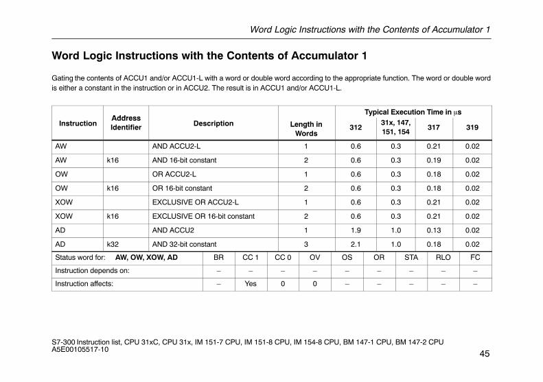
Word Logic Instructions with the Contents of Accumulator 1
Gating the contents of ACCU1 and/or ACCU1-L with a word or double word according to the appropriate function. The word or double wordis either a constant in the instruction or in ACCU2. The result is in ACCU1 and/or ACCU1-L.
AddressTypical Execution Time in �s
InstructionAddressIdentifier Description Length in
Words312
31x, 147,151, 154
317 319
AW AND ACCU2-L 1 0.6 0.3 0.21 0.02
AW k16 AND 16-bit constant 2 0.6 0.3 0.19 0.02
OW OR ACCU2-L 1 0.6 0.3 0.18 0.02
OW k16 OR 16-bit constant 2 0.6 0.3 0.18 0.02
XOW EXCLUSIVE OR ACCU2-L 1 0.6 0.3 0.21 0.02
XOW k16 EXCLUSIVE OR 16-bit constant 2 0.6 0.3 0.21 0.02
AD AND ACCU2 1 1.9 1.0 0.13 0.02
AD k32 AND 32-bit constant 3 2.1 1.0 0.18 0.02
Status word for: AW, OW, XOW, AD BR CC 1 CC 0 OV OS OR STA RLO FC
Instruction depends on: – – – – – – – – –
Instruction affects: – Yes 0 0 – – – – –
Word Logic Instructions with the Contents of Accumulator 1
46S7-300 Instruction list, CPU 31xC, CPU 31x, IM 151-7 CPU, IM 151-8 CPU, IM 154-8 CPU, BM 147-1 CPU, BM 147-2 CPU A5E00105517-10
AddressTypical Execution Time in �s
InstructionAddressIdentifier Description Length in
Words312
31x, 147,151, 154
317 319
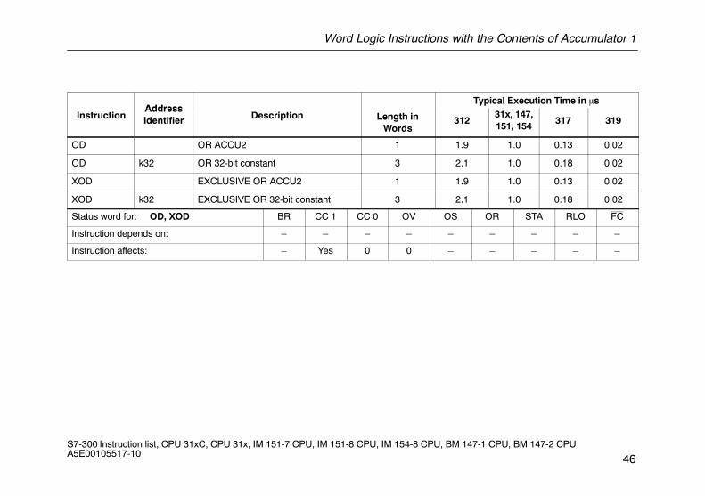
OD OR ACCU2 1 1.9 1.0 0.13 0.02
OD k32 OR 32-bit constant 3 2.1 1.0 0.18 0.02
XOD EXCLUSIVE OR ACCU2 1 1.9 1.0 0.13 0.02
XOD k32 EXCLUSIVE OR 32-bit constant 3 2.1 1.0 0.18 0.02
Status word for: OD, XOD BR CC 1 CC 0 OV OS OR STA RLO FC
Instruction depends on: – – – – – – – – –
Instruction affects: – Yes 0 0 – – – – –
Evaluating Conditions Using AND, OR and EXCLUSIVE OR
47S7-300 Instruction list, CPU 31xC, CPU 31x, IM 151-7 CPU, IM 151-8 CPU, IM 154-8 CPU, BM 147-1 CPU, BM 147-2 CPU A5E00105517-10
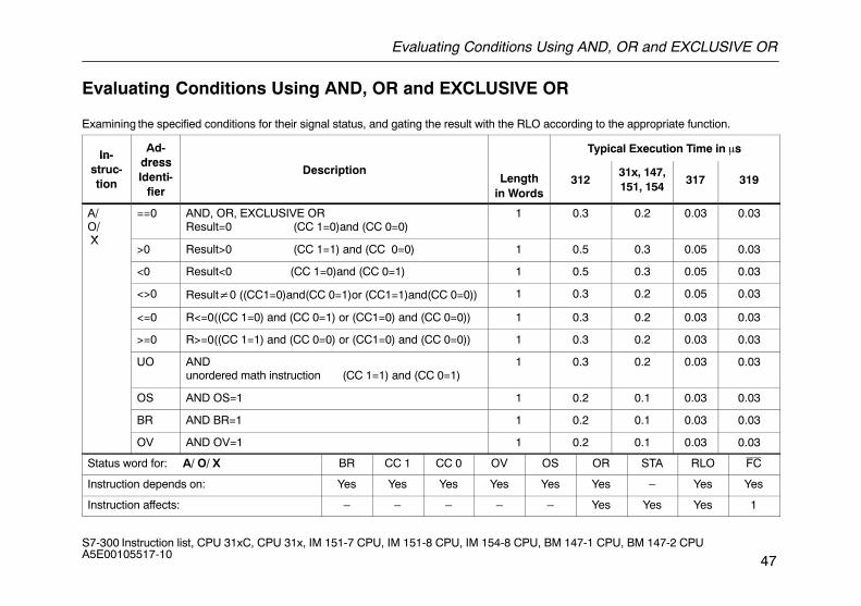
Evaluating Conditions Using AND, OR and EXCLUSIVE OR
Examining the specified conditions for their signal status, and gating the result with the RLO according to the appropriate function.
In-Ad-
dressTypical Execution Time in �sIn-
struc-tion
dressIdenti-
fier
DescriptionLength
in Words312
31x, 147,151, 154
317 319
A/O/ X
==0 AND, OR, EXCLUSIVE ORResult=0 (CC 1=0)and (CC 0=0)
1 0.3 0.2 0.03 0.03
X>0 Result>0 (CC 1=1) and (CC 0=0) 1 0.5 0.3 0.05 0.03
<0 Result<0 (CC 1=0)and (CC 0=1) 1 0.5 0.3 0.05 0.03
<>0 Result�0 ((CC1=0)and(CC 0=1)or (CC1=1)and(CC 0=0)) 1 0.3 0.2 0.05 0.03
<=0 R<=0((CC 1=0) and (CC 0=1) or (CC1=0) and (CC 0=0)) 1 0.3 0.2 0.03 0.03
>=0 R>=0((CC 1=1) and (CC 0=0) or (CC1=0) and (CC 0=0)) 1 0.3 0.2 0.03 0.03
UO ANDunordered math instruction (CC 1=1) and (CC 0=1)
1 0.3 0.2 0.03 0.03
OS AND OS=1 1 0.2 0.1 0.03 0.03
BR AND BR=1 1 0.2 0.1 0.03 0.03
OV AND OV=1 1 0.2 0.1 0.03 0.03
Status word for: A/ O/ X BR CC 1 CC 0 OV OS OR STA RLO FC
Instruction depends on: Yes Yes Yes Yes Yes Yes – Yes Yes
Instruction affects: – – – – – Yes Yes Yes 1
Evaluating Conditions Using AND, OR and EXCLUSIVE OR
48S7-300 Instruction list, CPU 31xC, CPU 31x, IM 151-7 CPU, IM 151-8 CPU, IM 154-8 CPU, BM 147-1 CPU, BM 147-2 CPU A5E00105517-10
In-Address
Typical Execution Time in �sIn-struc-tion
AddressIdentifier Description Length
in Words312
31x, 147,151, 154
317 319
AN/ ON/XN
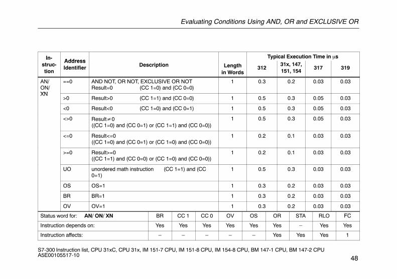
==0 AND NOT, OR NOT, EXCLUSIVE OR NOTResult=0 (CC 1=0) and (CC 0=0)
1 0.3 0.2 0.03 0.03
XN>0 Result>0 (CC 1=1) and (CC 0=0) 1 0.5 0.3 0.05 0.03
<0 Result<0 (CC 1=0) and (CC 0=1) 1 0.5 0.3 0.05 0.03
<>0 Result�0((CC 1=0) and (CC 0=1) or (CC 1=1) and (CC 0=0))
1 0.5 0.3 0.05 0.03
<=0 Result<=0((CC 1=0) and (CC 0=1) or (CC 1=0) and (CC 0=0))
1 0.2 0.1 0.03 0.03
>=0 Result>=0((CC 1=1) and (CC 0=0) or (CC 1=0) and (CC 0=0))
1 0.2 0.1 0.03 0.03
UO unordered math instruction (CC 1=1) and (CC0=1)
1 0.5 0.3 0.03 0.03
OS OS=1 1 0.3 0.2 0.03 0.03
BR BR=1 1 0.3 0.2 0.03 0.03
OV OV=1 1 0.3 0.2 0.03 0.03
Status word for: AN/ ON/ XN BR CC 1 CC 0 OV OS OR STA RLO FC
Instruction depends on: Yes Yes Yes Yes Yes Yes – Yes Yes
Instruction affects: – – – – – Yes Yes Yes 1
Edge-Triggered Instructions
49S7-300 Instruction list, CPU 31xC, CPU 31x, IM 151-7 CPU, IM 151-8 CPU, IM 154-8 CPU, BM 147-1 CPU, BM 147-2 CPU A5E00105517-10
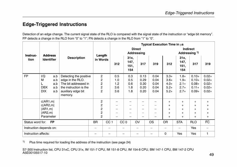
Edge-Triggered Instructions
Detection of an edge change. The current signal state of the RLO is compared with the signal state of the instruction or “edge bit memory”.FP detects a change in the RLO from “0” to “1”; FN detects a change in the RLO from “1” to “0”.
Typical Execution Time in �s
Instruc- Address Length
DirectAddressing
IndirectAddressing 1)
Instruc-tion
AddressIdentifier Description
Lengthin Words
312
31x,147,151,154
317 319 312
31x,147,151,154
317 319
FP I/Q a.bM a.bL a.b
Detecting the positiveedge in the RLO.The bit addressed in
222
0.51.01.2
0.30.50.6
0.130.290.30
0.040.040.04
3.3+3.6+4.0+
1.8+1.9+2.1+
0.10+0.10+0.08+
0.02+0.02+0.02+L a.b
DBX a.bDIX a.b
The bit addressed inthe instruction is theauxiliary edge bitmemory.
222
1.23.63.6
0.61.81.8
0.300.200.20
0.040.040.04
4.0+5.2+5.2+
2.1+2.7+2.7+
0.08+0.11+0.09+
0.02+0.02+0.02+
c[AR1,m]c[AR2,m][AR1,m][AR2,m]Parameter
22222
–––––
–––––
–––––
–––––
+++++
+++++
+++++
+++++
Status word for: FP BR CC 1 CC 0 OV OS OR STA RLO FC
Instruction depends on: – – – – – – – Yes –
Instruction affects: – – – – – 0 Yes Yes 1
1) Plus time required for loading the address of the instruction (see page 24)
Edge-Triggered Instructions
50S7-300 Instruction list, CPU 31xC, CPU 31x, IM 151-7 CPU, IM 151-8 CPU, IM 154-8 CPU, BM 147-1 CPU, BM 147-2 CPU A5E00105517-10
Typical Execution Time in �s
Instruc- Address Length
DirectAddressing
IndirectAddressing 1)
Instruc-tion
AddressIdentifier Description
Lengthin Words
312
31x,147,151,154
317 319 312
31x,147,151,154
317 319
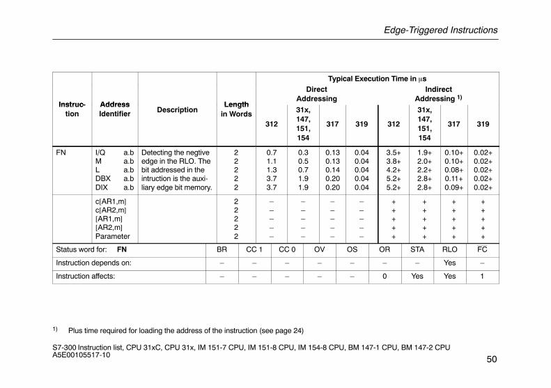
FN I/Q a.bM a.bL a.bDBX a.bDIX a.b
Detecting the negtiveedge in the RLO. Thebit addressed in theintruction is the auxi-liary edge bit memory.
22222
0.71.11.33.73.7
0.30.50.71.91.9
0.130.130.140.200.20
0.040.040.040.040.04
3.5+3.8+4.2+5.2+5.2+
1.9+2.0+2.2+2.8+2.8+
0.10+0.10+0.08+0.11+0.09+
0.02+0.02+0.02+0.02+0.02+
c[AR1,m]c[AR2,m][AR1,m][AR2,m]Parameter
22222
–––––
–––––
–––––
–––––
+++++
+++++
+++++
+++++
Status word for: FN BR CC 1 CC 0 OV OS OR STA RLO FC
Instruction depends on: – – – – – – – Yes –
Instruction affects: – – – – – 0 Yes Yes 1
1) Plus time required for loading the address of the instruction (see page 24)
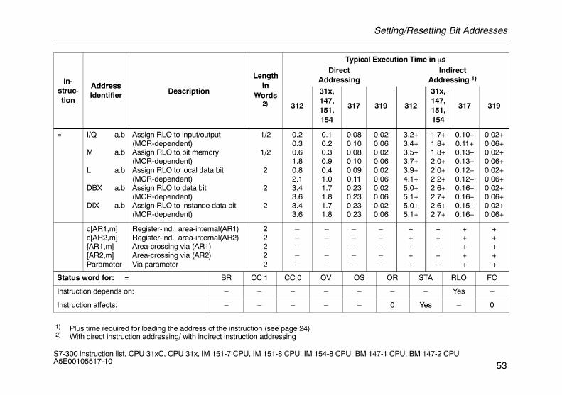
Setting/Resetting Bit Addresses
51S7-300 Instruction list, CPU 31xC, CPU 31x, IM 151-7 CPU, IM 151-8 CPU, IM 154-8 CPU, BM 147-1 CPU, BM 147-2 CPU A5E00105517-10
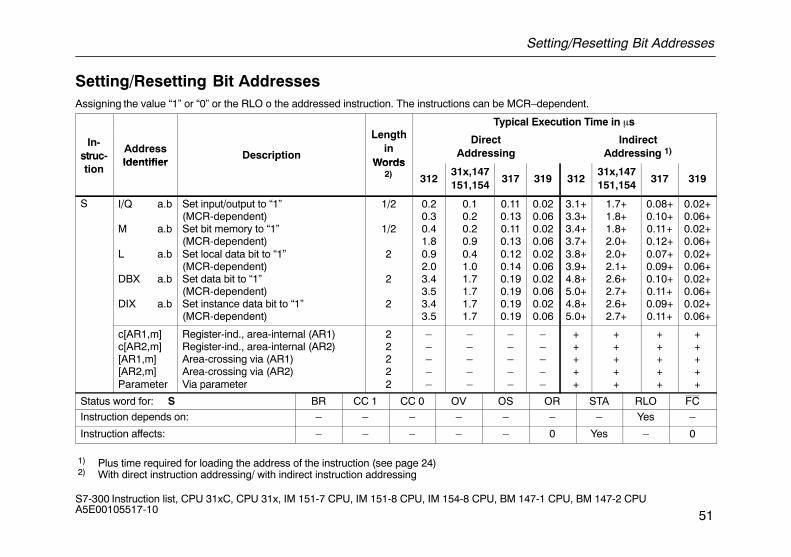
Setting/Resetting Bit AddressesAssigning the value “1” or “0” or the RLO o the addressed instruction. The instructions can be MCR–dependent.
L thTypical Execution Time in �s
In-struc-
AddressIdentifier
Description
Lengthin
Words
DirectAddressing
IndirectAddressing 1)struc
tionIdentifier
pWords
2) 31231x,147151,154
317 319 31231x,147151,154
317 319
S I/Q a.b
M a.b
L a.b
DBX a.b
DIX a.b
Set input/output to “1”(MCR-dependent)Set bit memory to “1”(MCR-dependent)Set local data bit to “1”(MCR-dependent)Set data bit to “1”(MCR-dependent)Set instance data bit to “1”(MCR-dependent)
1/2
1/2
2
2
2
0.20.30.41.80.92.03.43.53.43.5
0.10.20.20.90.41.01.71.71.71.7
0.110.130.110.130.120.140.190.190.190.19
0.020.060.020.060.020.060.020.060.020.06
3.1+3.3+3.4+3.7+3.8+3.9+4.8+5.0+4.8+5.0+
1.7+1.8+1.8+2.0+2.0+2.1+2.6+2.7+2.6+2.7+
0.08+0.10+0.11+0.12+0.07+0.09+0.10+0.11+0.09+0.11+
0.02+0.06+0.02+0.06+0.02+0.06+0.02+0.06+0.02+0.06+
c[AR1,m]c[AR2,m][AR1,m][AR2,m]Parameter
Register-ind., area-internal (AR1)Register-ind., area-internal (AR2)Area-crossing via (AR1)Area-crossing via (AR2)Via parameter
22222
–––––
–––––
–––––
–––––
+++++
+++++
+++++
+++++
Status word for: S BR CC 1 CC 0 OV OS OR STA RLO FC
Instruction depends on: – – – – – – – Yes –
Instruction affects: – – – – – 0 Yes – 0
1) Plus time required for loading the address of the instruction (see page 24) 2) With direct instruction addressing/ with indirect instruction addressing
Setting/Resetting Bit Addresses
52S7-300 Instruction list, CPU 31xC, CPU 31x, IM 151-7 CPU, IM 151-8 CPU, IM 154-8 CPU, BM 147-1 CPU, BM 147-2 CPU A5E00105517-10
Typical Execution Time in �s
AddressLength
DirectAddressing
IndirectAddressing 1)
InstructionAddressIdentifier Description
Lengthin
Word 2)312
31x,147,151,154
317 319 312
31x,147,151,154
317 319
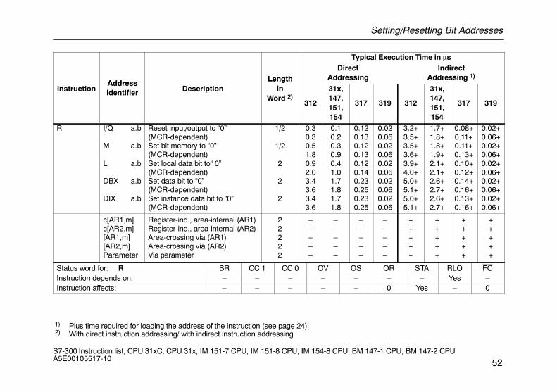
R I/Q a.b
M a.b
L a.b
DBX a.b
DIX a.b
Reset input/output to “0”(MCR-dependent)Set bit memory to “0”(MCR-dependent)Set local data bit to“ 0”(MCR-dependent)Set data bit to “0”(MCR-dependent)Set instance data bit to “0”(MCR-dependent)
1/2
1/2
2
2
2
0.30.30.51.80.92.03.43.63.43.6
0.10.20.30.90.41.01.71.81.71.8
0.120.130.120.130.120.140.230.250.230.25
0.020.060.020.060.020.060.020.060.020.06
3.2+3.5+3.5+3.6+3.9+4.0+5.0+5.1+5.0+5.1+
1.7+1.8+1.8+1.9+2.1+2.1+2.6+2.7+2.6+2.7+
0.08+0.11+0.11+0.13+0.10+0.12+0.14+0.16+0.13+0.16+
0.02+0.06+0.02+0.06+0.02+0.06+0.02+0.06+0.02+0.06+
c[AR1,m]c[AR2,m][AR1,m][AR2,m]Parameter
Register-ind., area-internal (AR1)Register-ind., area-internal (AR2)Area-crossing via (AR1)Area-crossing via (AR2)Via parameter
22222
–––––
–––––
–––––
–––––
+++++
+++++
+++++
+++++
Status word for: R BR CC 1 CC 0 OV OS OR STA RLO FCInstruction depends on: – – – – – – – Yes –Instruction affects: – – – – – 0 Yes – 0
1) Plus time required for loading the address of the instruction (see page 24) 2) With direct instruction addressing/ with indirect instruction addressing
Setting/Resetting Bit Addresses
53S7-300 Instruction list, CPU 31xC, CPU 31x, IM 151-7 CPU, IM 151-8 CPU, IM 154-8 CPU, BM 147-1 CPU, BM 147-2 CPU A5E00105517-10
Typical Execution Time in �s
In-Address
Lengthin
DirectAddressing
IndirectAddressing 1)In
struc-tion
AddressIdentifier Description
inWords
2) 312
31x,147,151,154
317 319 312
31x,147,151,154
317 319
= I/Q a.b
M a.b
L a.b
DBX a.b
DIX a.b
Assign RLO to input/output(MCR-dependent)Assign RLO to bit memory(MCR-dependent)Assign RLO to local data bit(MCR-dependent)Assign RLO to data bit(MCR-dependent)Assign RLO to instance data bit(MCR-dependent)
1/2
1/2
2
2
2
0.20.30.61.80.82.13.43.63.43.6
0.10.20.30.90.41.01.71.81.71.8
0.080.100.080.100.090.110.230.230.230.23
0.020.060.020.060.020.060.020.060.020.06
3.2+3.4+3.5+3.7+3.9+4.1+5.0+5.1+5.0+5.1+
1.7+1.8+1.8+2.0+2.0+2.2+2.6+2.7+2.6+2.7+
0.10+0.11+0.13+0.13+0.12+0.12+0.16+0.16+0.15+0.16+
0.02+0.06+0.02+0.06+0.02+0.06+0.02+0.06+0.02+0.06+
c[AR1,m]c[AR2,m][AR1,m][AR2,m]Parameter
Register-ind., area-internal(AR1)Register-ind., area-internal(AR2)Area-crossing via (AR1)Area-crossing via (AR2)Via parameter
22222
–––––
–––––
–––––
–––––
+++++
+++++
+++++
+++++
Status word for: = BR CC 1 CC 0 OV OS OR STA RLO FC
Instruction depends on: – – – – – – – Yes –
Instruction affects: – – – – – 0 Yes – 0
1) Plus time required for loading the address of the instruction (see page 24) 2) With direct instruction addressing/ with indirect instruction addressing
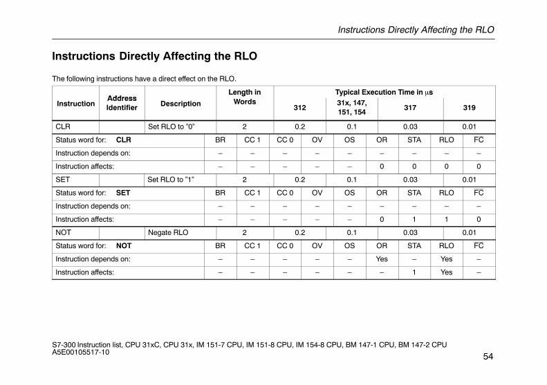
Instructions Directly Affecting the RLO
54S7-300 Instruction list, CPU 31xC, CPU 31x, IM 151-7 CPU, IM 151-8 CPU, IM 154-8 CPU, BM 147-1 CPU, BM 147-2 CPU A5E00105517-10
Instructions Directly Affecting the RLO
The following instructions have a direct effect on the RLO.
AddressLength in Typical Execution Time in �s
InstructionAddressIdentifier Description
gWords
31231x, 147,151, 154
317 319
CLR Set RLO to ”0” 2 0.2 0.1 0.03 0.01
Status word for: CLR BR CC 1 CC 0 OV OS OR STA RLO FC
Instruction depends on: – – – – – – – – –
Instruction affects: – – – – – 0 0 0 0
SET Set RLO to ”1” 2 0.2 0.1 0.03 0.01
Status word for: SET BR CC 1 CC 0 OV OS OR STA RLO FC
Instruction depends on: – – – – – – – – –
Instruction affects: – – – – – 0 1 1 0
NOT Negate RLO 2 0.2 0.1 0.03 0.01
Status word for: NOT BR CC 1 CC 0 OV OS OR STA RLO FC
Instruction depends on: – – – – – Yes – Yes –
Instruction affects: – – – – – – 1 Yes –
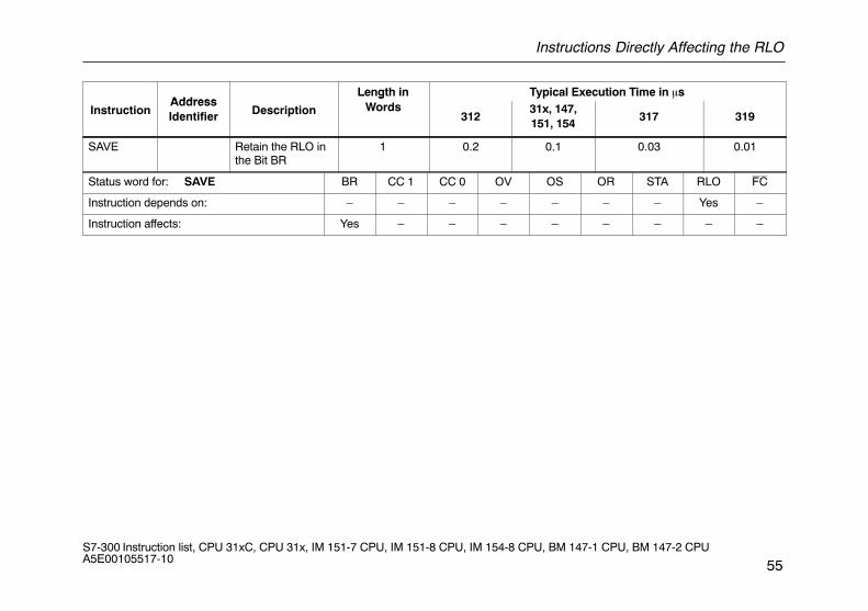
Instructions Directly Affecting the RLO
55S7-300 Instruction list, CPU 31xC, CPU 31x, IM 151-7 CPU, IM 151-8 CPU, IM 154-8 CPU, BM 147-1 CPU, BM 147-2 CPU A5E00105517-10
AddressLength in Typical Execution Time in �s
InstructionAddressIdentifier Description
gWords
31231x, 147,151, 154
317 319
SAVE Retain the RLO inthe Bit BR
1 0.2 0.1 0.03 0.01
Status word for: SAVE BR CC 1 CC 0 OV OS OR STA RLO FC
Instruction depends on: – – – – – – – Yes –
Instruction affects: Yes – – – – – – – –
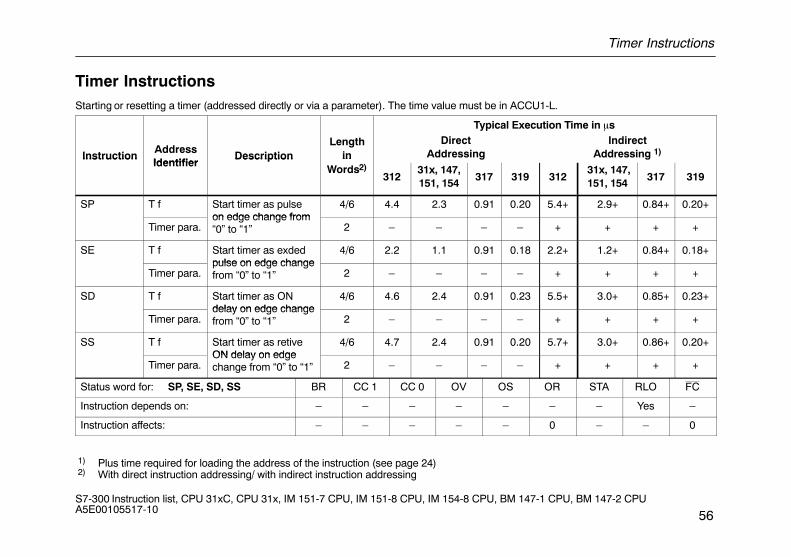
Timer Instructions
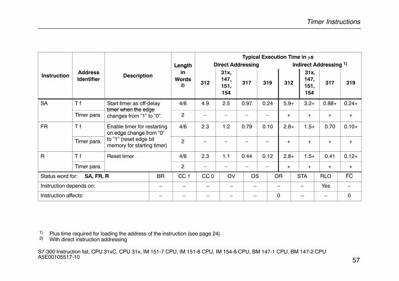
56S7-300 Instruction list, CPU 31xC, CPU 31x, IM 151-7 CPU, IM 151-8 CPU, IM 154-8 CPU, BM 147-1 CPU, BM 147-2 CPU A5E00105517-10
Timer InstructionsStarting or resetting a timer (addressed directly or via a parameter). The time value must be in ACCU1-L.
Typical Execution Time in �s
InstructionAddressIdentifier
DescriptionLength
inDirect
AddressingIndirect
Addressing 1)InstructionIdentifier
Description inWords2)
31231x, 147,151, 154
317 319 312 31x, 147,151, 154
317 319
SP T f Start timer as pulseon edge change from
4/6 4.4 2.3 0.91 0.20 5.4+ 2.9+ 0.84+ 0.20+
Timer para.on edge change from“0” to “1” 2 – – – – + + + +
SE T f Start timer as exdedpulse on edge change
4/6 2.2 1.1 0.91 0.18 2.2+ 1.2+ 0.84+ 0.18+
Timer para.pulse on edge changefrom “0” to “1” 2 – – – – + + + +
SD T f Start timer as ONdelay on edge change
4/6 4.6 2.4 0.91 0.23 5.5+ 3.0+ 0.85+ 0.23+
Timer para.delay on edge changefrom “0” to “1” 2 – – – – + + + +
SS T f Start timer as retiveON delay on edge
4/6 4.7 2.4 0.91 0.20 5.7+ 3.0+ 0.86+ 0.20+
Timer para.ON delay on edgechange from “0” to “1” 2 – – – – + + + +
Status word for: SP, SE, SD, SS BR CC 1 CC 0 OV OS OR STA RLO FC
Instruction depends on: – – – – – – – Yes –
Instruction affects: – – – – – 0 – – 0
1) Plus time required for loading the address of the instruction (see page 24) 2) With direct instruction addressing/ with indirect instruction addressing
Timer Instructions
57S7-300 Instruction list, CPU 31xC, CPU 31x, IM 151-7 CPU, IM 151-8 CPU, IM 154-8 CPU, BM 147-1 CPU, BM 147-2 CPU A5E00105517-10
Typical Execution Time in �s
Length Direct Addressing Indirect Addressing 1)
InstructionAddressIdentifier
Description
Lengthin
Words2) 312
31x,147,151,154
317 319 312
31x,147,151,154
317 319
SA T f Start timer as off-delaytimer when the edge
4/6 4.9 2.5 0.97 0.24 5.9+ 3.2+ 0.88+ 0.24+
Timer para.timer when the edgechanges from “1” to “0”. 2 – – – – + + + +
FR T f Enable timer for restartingon edge change from “0”
4/6 2.3 1.2 0.79 0.10 2.8+ 1.5+ 0.70 0.10+
Timer para.
on edge change from 0to “1” (reset edge bitmemory for starting timer)
2 – – – – + + + +
R T f Reset timer 4/6 2.3 1.1 0.44 0.12 2.8+ 1.5+ 0.41 0.12+
Timer para. 2 – – – – + + + +
Status word for: SA, FR, R BR CC 1 CC 0 OV OS OR STA RLO FC
Instruction depends on: – – – – – – – Yes –
Instruction affects: – – – – – 0 – – 0
1) Plus time required for loading the address of the instruction (see page 24) 2) With direct instruction addressing
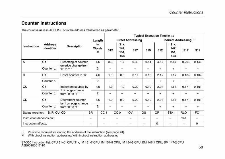
Counter Instructions
58S7-300 Instruction list, CPU 31xC, CPU 31x, IM 151-7 CPU, IM 151-8 CPU, IM 154-8 CPU, BM 147-1 CPU, BM 147-2 CPU A5E00105517-10
Counter InstructionsThe count value is in ACCU1-L or in the address transferred as parameter.
Typical Execution Time in �s
Length Direct Addressing Indirect Addressing 1)
InstructionAddressIdentifier
Description
Lengthin
Words2) 312
31x,147,151,154
317 319 312
31x,147,151,154
317 319
S C f Presetting of counteron edge change from
4/6 3.3 1.7 0.33 0.14 4.5+ 2.4+ 0.29+ 0.14+
Counter p.on edge change from“0” to “1” 2 – – – – + + + +
R C f Reset counter to “0” 4/6 1.3 0.6 0.17 0.10 2.1+ 1.1+ 0.13+ 0.10+
Counter p. 2 – – – – + + + +
CU C f Increment counter by1 on edge change
4/6 1.9 1.0 0.20 0.10 2.9+ 1.6+ 0.17+ 0.10+
Counter p.1 on edge changefrom “0” to “1” 2 – – – – + + + +
CD C f Decrement counterby 1 on edge change
4/6 1.9 0.9 0.20 0.10 2.9+ 1.5+ 0.17+ 0.10+
Counter p.by 1 on edge changefrom “0” to “1” 2 – – – – + + + +
Status word for: S, R, CU, CD BR CC 1 CC 0 OV OS OR STA RLO FC
Instruction depends on: – – – – – – – Yes –
Instruction affects: – – – – – 0 – – 0
1) Plus time required for loading the address of the instruction (see page 24) 2) With direct instruction addressing/ with indirect instruction addressing
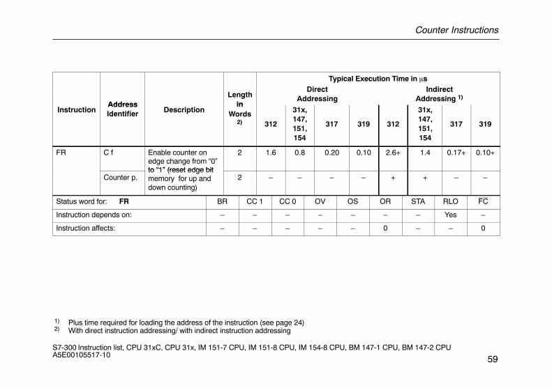
Counter Instructions
59S7-300 Instruction list, CPU 31xC, CPU 31x, IM 151-7 CPU, IM 151-8 CPU, IM 154-8 CPU, BM 147-1 CPU, BM 147-2 CPU A5E00105517-10
Typical Execution Time in �s
AddressLength
in
DirectAddressing
IndirectAddressing 1)
InstructionAddressIdentifier Description
inWords
2) 312
31x,147,151,154
317 319 312
31x,147,151,154
317 319
FR C f Enable counter onedge change from “0”to “1” (reset edge bit
2 1.6 0.8 0.20 0.10 2.6+ 1.4 0.17+ 0.10+
Counter p.to “1” (reset edge bitmemory for up anddown counting)
2 – – – – + + – –
Status word for: FR BR CC 1 CC 0 OV OS OR STA RLO FC
Instruction depends on: – – – – – – – Yes –
Instruction affects: – – – – – 0 – – 0
1) Plus time required for loading the address of the instruction (see page 24) 2) With direct instruction addressing/ with indirect instruction addressing
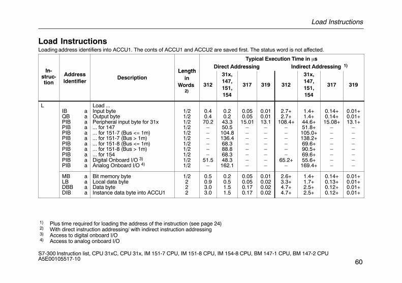
Load Instructions
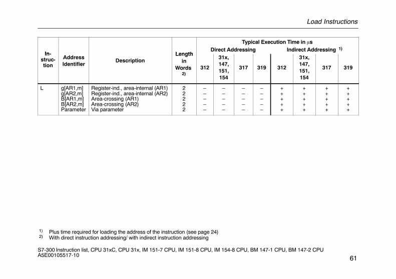
60S7-300 Instruction list, CPU 31xC, CPU 31x, IM 151-7 CPU, IM 151-8 CPU, IM 154-8 CPU, BM 147-1 CPU, BM 147-2 CPU A5E00105517-10
Load InstructionsLoading address identifiers into ACCU1. The conts of ACCU1 and ACCU2 are saved first. The status word is not affected.
Typical Execution Time in �s
In- LengthDirect Addressing Indirect Addressing 1)
In-struc-tion
AddressIdentifier
DescriptionLength
inWords
2)312
31x,147,151,154
317 319 312
31x,147,151,154
317 319
LIB aQB aPIB aPIB aPIB aPIB aPIB aPIB aPIB aPIB aPIB a
Load ...Input byteOutput bytePeripheral input byte for 31x... for 147... for 151-7 (Bus <= 1m)... for 151-7 (Bus > 1m)... for 151-8 (Bus <= 1m)... for 151-8 (Bus > 1m)... for 154Digital Onboard I/O 3)
Analog Onboard I/O 4)
1/21/21/21/21/21/21/21/21/21/21/2
0.40.470.2
––––––
51.5–
0.20.243.350.5104.8136.468.388.868.348.3162.1
0.050.0515.01
––––––––
0.010.0113.1
––––––––
2.7+2.7+
108.4+––––––
65.2+–
1.4+1.4+44.6+51.8+105.0+138.2+69.6+90.5+69.6+55.6+169.4+
0.14+0.14+15.08+
––––––––
0.01+0.01+13.1+
––––––––
MB aLB aDBB aDIB a
Bit memory byteLocal data byteData byteInstance data byte into ACCU1
1/2222
0.50.93.03.0
0.20.51.51.5
0.050.050.170.17
0.010.020.020.02
2.6+3.3+4.7+4.7+
1.4+1.7+2.5+2.5+
0.14+0.13+0.12+0.12+
0.01+0.01+0.01+0.01+
1) Plus time required for loading the address of the instruction (see page 24) 2) With direct instruction addressing/ with indirect instruction addressing 3) Access to digital onboard I/O 4) Access to analog onboard I/O
Load Instructions
61S7-300 Instruction list, CPU 31xC, CPU 31x, IM 151-7 CPU, IM 151-8 CPU, IM 154-8 CPU, BM 147-1 CPU, BM 147-2 CPU A5E00105517-10
Typical Execution Time in �s
In- LengthDirect Addressing Indirect Addressing 1)
In-struc-tion
AddressIdentifier
DescriptionLength
inWords
2)312
31x,147,151,154
317 319 312
31x,147,151,154
317 319
L g[AR1,m]g[AR2,m]B[AR1,m]B[AR2,m]Parameter
Register-ind., area-internal (AR1)Register-ind., area-internal (AR2)Area-crossing (AR1)Area-crossing (AR2)Via parameter
22222
–––––
–––––
–––––
–––––
+++++
+++++
+++++
+++++
1) Plus time required for loading the address of the instruction (see page 24) 2) With direct instruction addressing/ with indirect instruction addressing
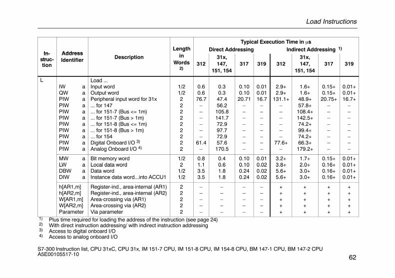
Load Instructions
62S7-300 Instruction list, CPU 31xC, CPU 31x, IM 151-7 CPU, IM 151-8 CPU, IM 154-8 CPU, BM 147-1 CPU, BM 147-2 CPU A5E00105517-10
Typical Execution Time in �s
In- AddressLength Direct Addressing Indirect Addressing 1)
In-struc-tion
AddressIdentifier Description
gin
Words2)
31231x,147,
151, 154317 319 312
31x,147,
151, 154317 319
LIW aQW aPIW aPIW aPIW aPIW aPIW aPIW aPIW aPIW aPIW a
Load ...Input wordOutput wordPeripheral input word for 31x... for 147... for 151-7 (Bus <= 1m)... for 151-7 (Bus > 1m)... for 151-8 (Bus <= 1m)... for 151-8 (Bus > 1m)... for 154Digital Onboard I/O 3)
Analog Onboard I/O 4)
1/21/2222222222
0.60.676.7
––––––
61.4–
0.30.347.456.2105.8141.772.997.772.957.6170.5
0.100.1020.71
––––––––
0.010.0116.7
––––––––
2.9+2.9+
131.1+––––––
77.6+–
1.6+1.6+48.9+57.8+108.4+142.5+74.2+99.4+74.2+66.3+179.2+
0.15+0.15+20.75+
––––––––
0.01+0.01+16.7+
––––––––
MW aLW a
Bit memory wordLocal data word
1/22
0.81.1
0.40.6
0.100.10
0.010.02
3.2+3.8+
1.7+2.0+
0.15+0.16+
0.01+0.01+LW a
DBW aDIW a
Local data wordData wordInstance data word...into ACCU1
21/21/2
1.13.53.5
0.61.81.8
0.100.240.24
0.020.020.02
3.8+5.6+5.6+
2.0+3.0+3.0+
0.16+0.16+0.16+
0.01+0.01+0.01+
h[AR1,m]h[AR2,m]W[AR1,m]W[AR2,m]Parameter
Register-ind., area-internal (AR1)Register-ind., area-internal (AR2)Area-crossing via (AR1)Area-crossing via (AR2)Via parameter
22222
–––––
–––––
–––––
–––––
+++++
+++++
+++++
+++++
1) Plus time required for loading the address of the instruction (see page 24) 2) With direct instruction addressing/ with indirect instruction addressing 3) Access to digital onboard I/O 4) Access to analog onboard I/O
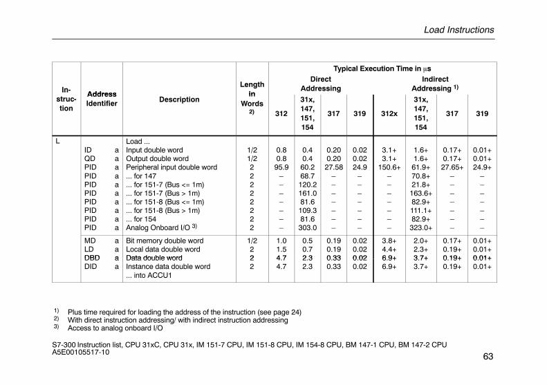
Load Instructions
63S7-300 Instruction list, CPU 31xC, CPU 31x, IM 151-7 CPU, IM 151-8 CPU, IM 154-8 CPU, BM 147-1 CPU, BM 147-2 CPU A5E00105517-10
Typical Execution Time in �s
In-Address
Lengthin
DirectAddressing
IndirectAddressing 1)In
struc-tion
AddressIdentifier Description
inWords
2) 312
31x,147,151,154
317 319 312x
31x,147,151,154
317 319
LID aQD aPID aPID aPID aPID aPID aPID aPID aPID a
Load ...Input double wordOutput double wordPeripheral input double word... for 147... for 151-7 (Bus <= 1m)... for 151-7 (Bus > 1m)... for 151-8 (Bus <= 1m)... for 151-8 (Bus > 1m)... for 154Analog Onboard I/O 3)
1/21/222222222
0.80.895.9
–––––––
0.40.460.268.7120.2161.081.6109.381.6303.0
0.200.2027.58
–––––––
0.020.0224.9
–––––––
3.1+3.1+
150.6+–––––––
1.6+1.6+61.9+70.8+21.8+163.6+82.9+111.1+82.9+323.0+
0.17+0.17+27.65+
–––––––
0.01+0.01+24.9+
–––––––
MD aLD aDBD a
Bit memory double wordLocal data double wordData double word
1/222
1.01.54 7
0.50.72 3
0.190.190 33
0.020.020 02
3.8+4.4+6 9+
2.0+2.3+3 7+
0.17+0.19+0 19+
0.01+0.01+0 01+DBD a
DID aData double wordInstance data double word... into ACCU1
22
4.74.7
2.32.3
0.330.33
0.020.02
6.9+6.9+
3.7+3.7+
0.19+0.19+
0.01+0.01+
1) Plus time required for loading the address of the instruction (see page 24) 2) With direct instruction addressing/ with indirect instruction addressing 3) Access to analog onboard I/O
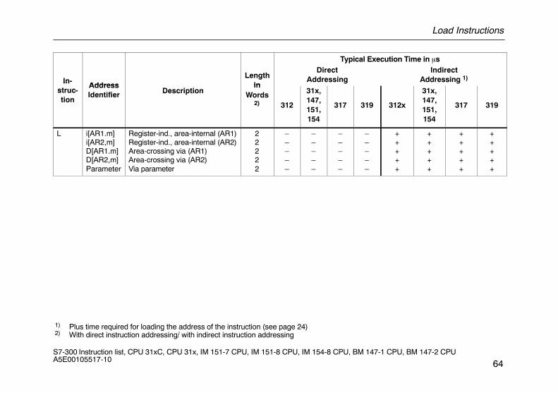
Load Instructions
64S7-300 Instruction list, CPU 31xC, CPU 31x, IM 151-7 CPU, IM 151-8 CPU, IM 154-8 CPU, BM 147-1 CPU, BM 147-2 CPU A5E00105517-10
Typical Execution Time in �s
In-Address
Lengthin
DirectAddressing
IndirectAddressing 1)In
struc-tion
AddressIdentifier Description
inWords
2) 312
31x,147,151,154
317 319 312x
31x,147,151,154
317 319
L i[AR1.m]i[AR2,m]D[AR1.m]D[AR2,m]Parameter
Register-ind., area-internal (AR1)Register-ind., area-internal (AR2)Area-crossing via (AR1)Area-crossing via (AR2)Via parameter
22222
–––––
–––––
–––––
–––––
+++++
+++++
+++++
+++++
1) Plus time required for loading the address of the instruction (see page 24) 2) With direct instruction addressing/ with indirect instruction addressing
Load Instructions
65S7-300 Instruction list, CPU 31xC, CPU 31x, IM 151-7 CPU, IM 151-8 CPU, IM 154-8 CPU, BM 147-1 CPU, BM 147-2 CPU A5E00105517-10
Typical Execution Time in �s
Instruc- AddressLength
DirectAddressing
IndirectAddressing 1)
Instruc-tion
AddressIdentifier Description
Lengthin
Words312
31x,147,151,154
317 319 312
31x,147,151,154
317 319
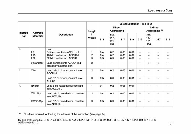
Lk8k16k32
Load ...8-bit constant into ACCU1-LL16-bit constant into ACCU1-L32-bit constant into ACCU1
123
0.40.40.5
0.20.20.3
0.050.050.05
0.010.010.01
–––
–––
–––
–––
Parameter Load constant into ACCU1 (ad- 2 – – – – + + + +Parameter Load constant into ACCU1 (addressed via parameter)
2 + + + +
L 2#n Load 16-bit binary constant intoACCU1-L
2 0.4 0.2 0.05 0.01 – – – –
Load 32-bit binary constant intoACCU1
3 0.5 0.3 0.05 0.01 – – – –
L B#8#p Load 8-bit hexadecimal constantinto ACCU1-L
1 0.4 0.2 0.05 0.01 – – – –
W#16#p Load 16-bit hexadecimal constantinto ACCU1-L
2 0.4 0.2 0.05 0.01 – – – –
DW#16#p Load 32-bit hexadecimal constantinto ACCU1-L
3 0.5 0.3 0.05 0.01 – – – –
1) Plus time required for loading the address of the instruction (see page 24)
Load Instructions
66S7-300 Instruction list, CPU 31xC, CPU 31x, IM 151-7 CPU, IM 151-8 CPU, IM 154-8 CPU, BM 147-1 CPU, BM 147-2 CPU A5E00105517-10
Typical Execution Time in �sAdd
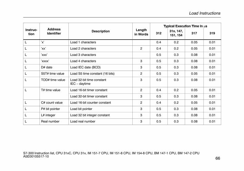
Typical Execution Time in �sInstruc-
tionAddressIdentifier
Description Lengthin Words 312
31x, 147,151, 154
317 319
L ’x’ Load 1 characters 0.4 0.2 0.05 0.01
L ’xx’ Load 2 characters 2 0.4 0.2 0.05 0.01
L ’xxx’ Load 3 characters 0.5 0.3 0.08 0.01
L ’xxxx’ Load 4 characters 3 0.5 0.3 0.08 0.01
L D# date Load IEC date (BCD) 3 0.5 0.3 0.08 0.01
L S5T# time value Load S5 time constant (16 bits) 2 0.5 0.3 0.05 0.01
L TOD# time value Load 32-bit time constantIEC – daytime
3 0.5 0.3 0.08 0.01
L T# time value Load 16-bit timer constant 2 0.4 0.2 0.05 0.01
Load 32-bit timer constant 3 0.5 0.3 0.08 0.01
L C# count value Load 16-bit counter constant 2 0.4 0.2 0.05 0.01
L P# bit pointer Load bit pointer 3 0.5 0.3 0.08 0.01
L L# integer Load 32 bit integer constant 3 0.5 0.3 0.08 0.01
L Real number Load real number 3 0.5 0.3 0.08 0.01
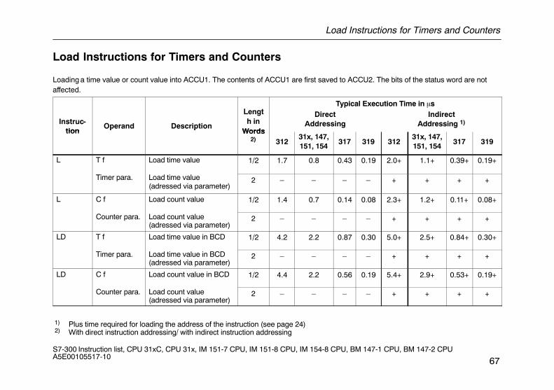
Load Instructions for Timers and Counters
67S7-300 Instruction list, CPU 31xC, CPU 31x, IM 151-7 CPU, IM 151-8 CPU, IM 154-8 CPU, BM 147-1 CPU, BM 147-2 CPU A5E00105517-10
Load Instructions for Timers and Counters
Loading a time value or count value into ACCU1. The contents of ACCU1 are first saved to ACCU2. The bits of the status word are notaffected.
L tTypical Execution Time in �s
Instruc-tion
Operand Description
Length in
Words
DirectAddressing
IndirectAddressing 1)
tionp p
Words2) 312
31x, 147,151, 154
317 319 31231x, 147,151, 154
317 319
L T f Load time value 1/2 1.7 0.8 0.43 0.19 2.0+ 1.1+ 0.39+ 0.19+
Timer para. Load time value(adressed via parameter)
2 – – – – + + + +
L C f Load count value 1/2 1.4 0.7 0.14 0.08 2.3+ 1.2+ 0.11+ 0.08+
Counter para. Load count value(adressed via parameter)
2 – – – – + + + +
LD T f Load time value in BCD 1/2 4.2 2.2 0.87 0.30 5.0+ 2.5+ 0.84+ 0.30+
Timer para. Load time value in BCD(adressed via parameter)
2 – – – – + + + +
LD C f Load count value in BCD 1/2 4.4 2.2 0.56 0.19 5.4+ 2.9+ 0.53+ 0.19+
Counter para. Load count value(adressed via parameter)
2 – – – – + + + +
1) Plus time required for loading the address of the instruction (see page 24) 2) With direct instruction addressing/ with indirect instruction addressing
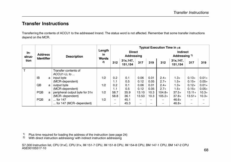
Transfer Instructions
68S7-300 Instruction list, CPU 31xC, CPU 31x, IM 151-7 CPU, IM 151-8 CPU, IM 154-8 CPU, BM 147-1 CPU, BM 147-2 CPU A5E00105517-10
Transfer Instructions
Transferring the contents of ACCU1 to the addressed Inrand. The status word is not affected. Remember that some transfer instructionsdepend on the MCR.
LengthTypical Execution Time in �s
In-struc-
AddressIdentifier
Description
Lengthin
Words
DirectAddressing
IndirectAddressing 1)struc
tionIdentifier
DescriptionWords
2) 31231x,147,151,154
317 319 31231x,147,151,154
317 319
T
IB a
QB a
PQB a
PQB a
Transfer contents ofACCU1-LL to ...input byte(MCR-dependent)output byte(MCR-dependent)peripheral output byte for 31x(MCR–dependent)... for 147... for 147 (MCR–dependent)
1/2
1/2
1/2
1/2
0.21.10.21.158.758.8
––
0.10.50.10.535.936.145.145.3
0.060.120.060.1213.1013.53
––
0.010.050.010.0510.310.3
––
2.4+2.7+2.4+2.7+
104.8+105.2+
––
1.3+1.5+1.3+1.5+37.5+37.8+46.6+46.8+
0.13+0.15+0.12+0.15+13.11+13.51+
––
0.01+0.05+0.01+0.05+10.3+10.3+
––
1) Plus time required for loading the address of the instruction (see page 24) 2) With direct instruction addressing/ with indirect instruction addressing
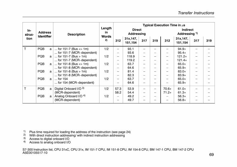
Transfer Instructions
69S7-300 Instruction list, CPU 31xC, CPU 31x, IM 151-7 CPU, IM 151-8 CPU, IM 154-8 CPU, BM 147-1 CPU, BM 147-2 CPU A5E00105517-10
LengthTypical Execution Time in �s
In-struc-
AddressIdentifier
Description
Lengthin
Words
DirectAddressing
IndirectAddressing 1)struc
tionIdentifier
DescriptionWords
2) 31231x,147,151,154
317 319 31231x,147,151,154
317 319
T PQB a
PQB a
PQB a
PQB a
PQB a
... for 151-7 (Bus <= 1m)
... for 151-7 (MCR–dependent)
... for 151-7 (Bus > 1m)
... for 151-7 (MCR–dependent)
... for 151-8 (Bus <= 1m)
... for 151-8 (MCR–dependent)
... for 151-8 (Bus > 1m)
... for 151-8 (MCR–dependent)
... for 154
... for 154 (MCR–dependent)
1/2
1/2
1/2
1/2
1/2
––––––––––
93.193.6118.9119.263.764.681.482.363.764.6
––––––––––
––––––––––
––––––––––
94.9+95.4+121.2+121.4+65.0+65.9+83.0+83.9+65.0+65.9+
––––––––––
––––––––––
T PQB a
PQB a
Digital Onboard I/O 3)
(MCR-dependent)Analog Onboard I/O 4)
(MCR-dependent)
1/2
1/2
57.358.2
––
53.954.449.249.7
––––
––––
70.6+71.2+
––
61.0+61.3+56.3+56.8+
––––
––––
1) Plus time required for loading the address of the instruction (see page 24) 2) With direct instruction addressing/ with indirect instruction addressing 3) Access to digital onboard I/O 4) Access to analog onboard I/O
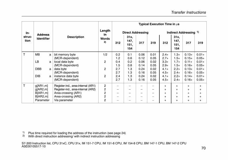
Transfer Instructions
70S7-300 Instruction list, CPU 31xC, CPU 31x, IM 151-7 CPU, IM 151-8 CPU, IM 154-8 CPU, BM 147-1 CPU, BM 147-2 CPU A5E00105517-10
Length
Typical Execution Time in �s
In-Address
Lengthin
Direct Addressing Indirect Addressing 1)Instruc-tion
AddressIdentifier Description
inWords
2) 312
31x,147,151,154
317 319 312
31x,147,151,154
317 319
T MB a
LB a
DBB a
DIB a
bit memory byte(MCR-dependent)local data byte(MCR-dependent)data byte(MCR-dependent)instance data byte(MCR-dependent)
1/2
2
2
2
0.21.20.41.52.72.72.42.7
0.10.60.20.81.31.31.31.3
0.060.120.060.140.240.160.240.16
0.010.050.020.050.020.050.020.05
2.4+2.7+3.3+2.9+4.1+4.5+4.1+4.5+
1.3+1.5+1.7+1.5+2.2+2.4+2.2+2.4+
0.13+0.15+0.11+0.16+0.13+0.16+0.14+0.16+
0.01+0.05+0.01+0.05+0.01+0.05+0.01+0.05+
T g[AR1,m]g[AR2,m]B[AR1,m]B[AR2,m]Parameter
Register-ind., area-internal (AR1)Register-ind., area-internal (AR2)Area-crossing (AR1)Area-crossing (AR2)Via parameter
22222
–––––
–––––
–––––
–––––
+++++
+++++
+++++
+++++
1) Plus time required for loading the address of the instruction (see page 24) 2) With direct instruction addressing/ with indirect instruction addressing
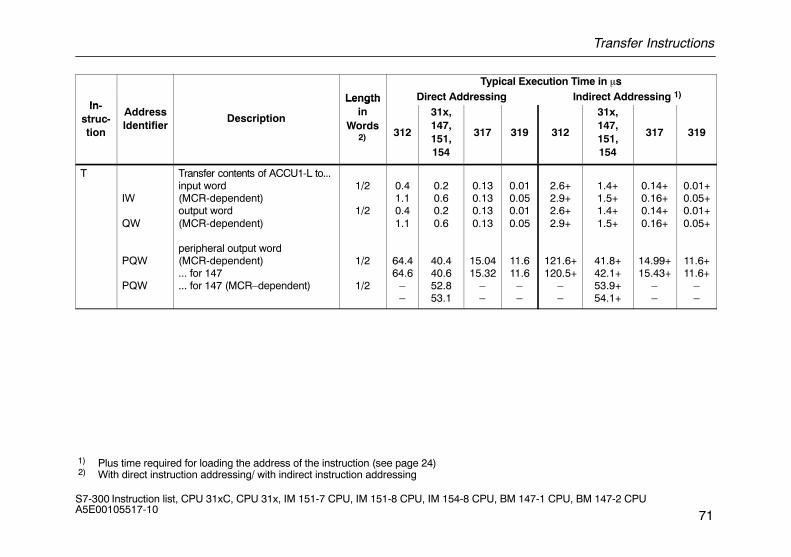
Transfer Instructions
71S7-300 Instruction list, CPU 31xC, CPU 31x, IM 151-7 CPU, IM 151-8 CPU, IM 154-8 CPU, BM 147-1 CPU, BM 147-2 CPU A5E00105517-10
Typical Execution Time in �s
InLength Direct Addressing Indirect Addressing 1)
In-struc-tion
AddressIdentifier
Description
Lengthin
Words2) 312
31x,147,151,154
317 319 312
31x,147,151,154
317 319
T
IW
QW
PQW
PQW
Transfer contents of ACCU1-L to...input word(MCR-dependent)output word(MCR-dependent)
peripheral output word(MCR-dependent)... for 147... for 147 (MCR–dependent)
1/2
1/2
1/2
1/2
0.41.10.41.1
64.464.6
––
0.20.60.20.6
40.440.652.853.1
0.130.130.130.13
15.0415.32
––
0.010.050.010.05
11.611.6
––
2.6+2.9+2.6+2.9+
121.6+120.5+
––
1.4+1.5+1.4+1.5+
41.8+42.1+53.9+54.1+
0.14+0.16+0.14+0.16+
14.99+15.43+
––
0.01+0.05+0.01+0.05+
11.6+11.6+
––
1) Plus time required for loading the address of the instruction (see page 24) 2) With direct instruction addressing/ with indirect instruction addressing
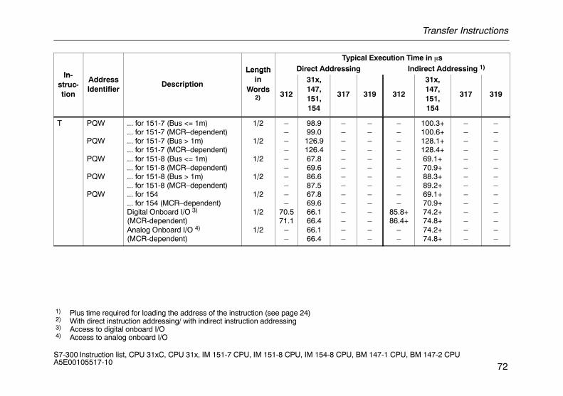
Transfer Instructions
72S7-300 Instruction list, CPU 31xC, CPU 31x, IM 151-7 CPU, IM 151-8 CPU, IM 154-8 CPU, BM 147-1 CPU, BM 147-2 CPU A5E00105517-10
Typical Execution Time in �s
InLength Direct Addressing Indirect Addressing 1)
In-struc-tion
AddressIdentifier
Description
Lengthin
Words2) 312
31x,147,151,154
317 319 312
31x,147,151,154
317 319
T PQW
PQW
PQW
PQW
PQW
... for 151-7 (Bus <= 1m)
... for 151-7 (MCR–dependent)
... for 151-7 (Bus > 1m)
... for 151-7 (MCR–dependent)
... for 151-8 (Bus <= 1m)
... for 151-8 (MCR–dependent)
... for 151-8 (Bus > 1m)
... for 151-8 (MCR–dependent)
... for 154
... for 154 (MCR–dependent)Digital Onboard I/O 3)
(MCR-dependent)Analog Onboard I/O 4)
(MCR-dependent)
1/2
1/2
1/2
1/2
1/2
1/2
1/2
––––––––––
70.571.1
––
98.999.0126.9126.467.869.686.687.567.869.666.166.466.166.4
––––––––––––––
––––––––––––––
––––––––––
85.8+86.4+
––
100.3+100.6+128.1+128.4+69.1+70.9+88.3+89.2+69.1+70.9+74.2+74.8+74.2+74.8+
––––––––––––––
––––––––––––––
1) Plus time required for loading the address of the instruction (see page 24) 2) With direct instruction addressing/ with indirect instruction addressing 3) Access to digital onboard I/O 4) Access to analog onboard I/O
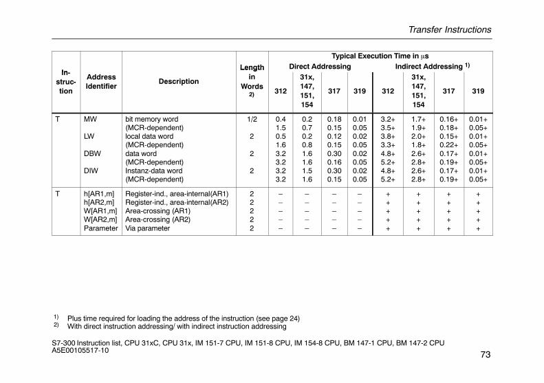
Transfer Instructions
73S7-300 Instruction list, CPU 31xC, CPU 31x, IM 151-7 CPU, IM 151-8 CPU, IM 154-8 CPU, BM 147-1 CPU, BM 147-2 CPU A5E00105517-10
Typical Execution Time in �s
InLength Direct Addressing Indirect Addressing 1)
In-struc-tion
AddressIdentifier
Description
Lengthin
Words2) 312
31x,147,151,154
317 319 312
31x,147,151,154
317 319
T MW
LW
DBW
DIW
bit memory word(MCR-dependent)local data word(MCR-dependent)data word(MCR-dependent)Instanz-data word(MCR-dependent)
1/2
2
2
2
0.41.50.51.63.23.23.23.2
0.20.70.20.81.61.61.51.6
0.180.150.120.150.300.160.300.15
0.010.050.020.050.020.050.020.05
3.2+3.5+3.8+3.3+4.8+5.2+4.8+5.2+
1.7+1.9+2.0+1.8+2.6+2.8+2.6+2.8+
0.16+0.18+0.15+0.22+0.17+0.19+0.17+0.19+
0.01+0.05+0.01+0.05+0.01+0.05+0.01+0.05+
T h[AR1,m]h[AR2,m]W[AR1,m]W[AR2,m]Parameter
Register-ind., area-internal(AR1)Register-ind., area-internal(AR2)Area-crossing (AR1)Area-crossing (AR2)Via parameter
22222
–––––
–––––
–––––
–––––
+++++
+++++
+++++
+++++
1) Plus time required for loading the address of the instruction (see page 24) 2) With direct instruction addressing/ with indirect instruction addressing
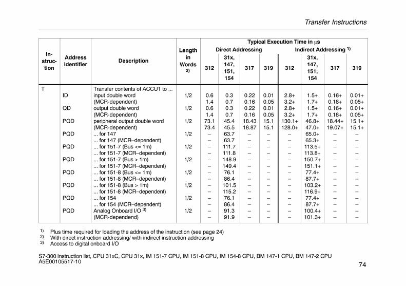
Transfer Instructions
74S7-300 Instruction list, CPU 31xC, CPU 31x, IM 151-7 CPU, IM 151-8 CPU, IM 154-8 CPU, BM 147-1 CPU, BM 147-2 CPU A5E00105517-10
Typical Execution Time in �s
InLength Direct Addressing Indirect Addressing 1)
In-struc-tion
AddressIdentifier
Description
Lengthin
Words2) 312
31x,147,151,154
317 319 312
31x,147,151,154
317 319
TID
QD
PQD
PQD
PQD
PQD
PQD
PQD
PQD
PQD
Transfer contents of ACCU1 to ...input double word(MCR-dependent)output double word(MCR-dependent)peripheral output double word(MCR-dependent)... for 147... for 147 (MCR–dependent)... for 151-7 (Bus <= 1m)... for 151-7 (MCR–dependent)... for 151-7 (Bus > 1m)... for 151-7 (MCR–dependent)... for 151-8 (Bus <= 1m)... for 151-8 (MCR–dependent)... for 151-8 (Bus > 1m)... for 151-8 (MCR–dependent)... for 154... for 154 (MCR–dependent)Analog Onboard I/O 3)
(MCR-dependend)
1/2
1/2
1/2
1/2
1/2
1/2
1/2
1/2
1/2
1/2
0.61.40.61.473.173.4
––––––––––––––
0.30.70.30.745.445.563.763.7111.7111.8148.9149.476.186.4101.5115.276.186.491.391.9
0.220.160.220.1618.4318.87
––––––––––––––
0.010.050.010.0515.115.1
––––––––––––––
2.8+3.2+2.8+3.2+
130.1+128.0+
––––––––––––––
1.5+1.7+1.5+1.7+46.8+47.0+65.0+65.3+113.5+113.8+150.7+151.1+77.4+87.7+103.2+116.9+77.4+87.7+100.4+101.3+
0.16+0.18+0.16+0.18+18.44+19.07+
––––––––––––––
0.01+0.05+0.01+0.05+15.1+15.1+
––––––––––––––
1) Plus time required for loading the address of the instruction (see page 24) 2) With direct instruction addressing/ with indirect instruction addressing 3) Access to digital onboard I/O
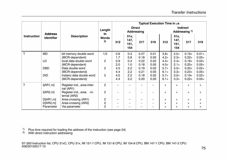
Transfer Instructions
75S7-300 Instruction list, CPU 31xC, CPU 31x, IM 151-7 CPU, IM 151-8 CPU, IM 154-8 CPU, BM 147-1 CPU, BM 147-2 CPU A5E00105517-10
Typical Execution Time in �s
AddressLength
in
DirectAddressing
IndirectAddressing 1)
InstructionAddressIdentifier Description
inWords
2) 312
31x,147,151,154
317 319 312
31x,147,151,154
317 319
T MD
LD
DBD
DID
bit memory double word(MCR-dependent)local data double word(MCR-dependent)Data double word(MCR-dependend)Instanz data double word(MCR-dependend)
1/2
2
2
2
0.61.70.92.04.54.44.54.4
0.30.80.41.02.22.22.22.2
0.270.180.220.180.190.210.180.20
0.010.050.020.050.020.050.020.05
3.8+4.2+4.4+4.0+5.7+6.1+5.7+6.1+
2.0+2.3+2.4+2.1+3.0+3.3+3.0+3.3+
0.19+0.22+0.18+0.25+0.20+0.23+0.19+0.22+
0.01+0.05+0.02+0.05+0.02+0.05+0.02+0.05+
T i[AR1,m]
i[AR2,m]
D[AR1,m]D[AR2,m]Parameter
Register-ind., area-inter-nal (AR1)Register-ind., area -in-ternal (AR2)Area-crossing (AR1)Area-crossing (AR2)Via parameter
2
2
222
–
–
–––
–
–
–––
–
–
–––
–
–
–––
+
+
+++
+
+
+++
+
+
+++
+
+
+++
1) Plus time required for loading the address of the instruction (see page 24) 2) With direct instruction addressing
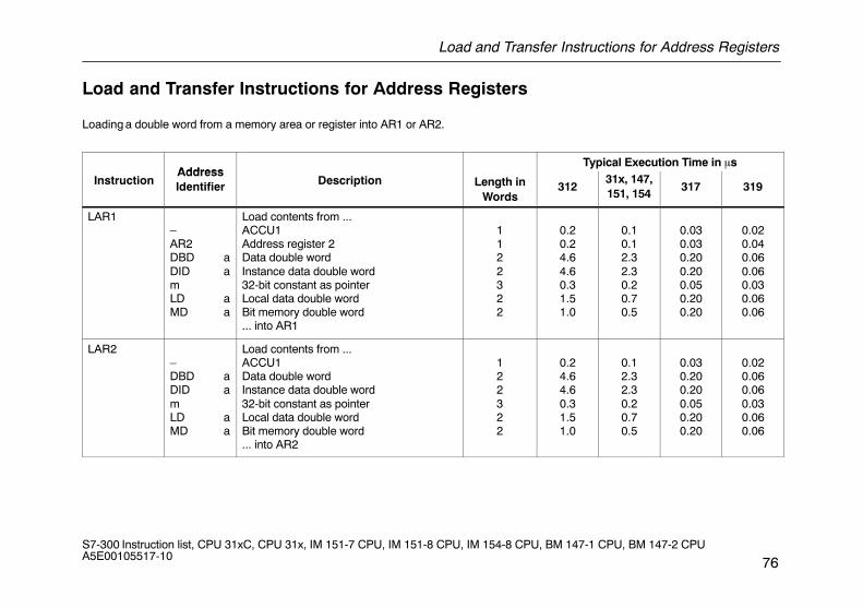
Load and Transfer Instructions for Address Registers
76S7-300 Instruction list, CPU 31xC, CPU 31x, IM 151-7 CPU, IM 151-8 CPU, IM 154-8 CPU, BM 147-1 CPU, BM 147-2 CPU A5E00105517-10
Load and Transfer Instructions for Address Registers
Loading a double word from a memory area or register into AR1 or AR2.
AddressTypical Execution Time in �s
InstructionAddressIdentifier Description Length in
Words312
31x, 147,151, 154
317 319
LAR1–AR2DBD aDID amLD aMD a
Load contents from ...ACCU1Address register 2Data double wordInstance data double word32-bit constant as pointerLocal data double wordBit memory double word... into AR1
1122322
0.20.24.64.60.31.51.0
0.10.12.32.30.20.70.5
0.030.030.200.200.050.200.20
0.020.040.060.060.030.060.06
LAR2–DBD aDID amLD aMD a
Load contents from ...ACCU1Data double wordInstance data double word32-bit constant as pointerLocal data double wordBit memory double word... into AR2
122322
0.24.64.60.31.51.0
0.12.32.30.20.70.5
0.030.200.200.050.200.20
0.020.060.060.030.060.06
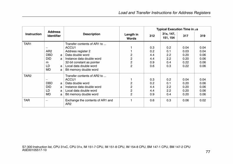
Load and Transfer Instructions for Address Registers
77S7-300 Instruction list, CPU 31xC, CPU 31x, IM 151-7 CPU, IM 151-8 CPU, IM 154-8 CPU, BM 147-1 CPU, BM 147-2 CPU A5E00105517-10
AddressTypical Execution Time in �s
InstructionAddressIdentifier Description Length in
Words312
31x, 147,151, 154
317 319
TAR1–AR2DBD aDID amLD aMD a
Transfer contents of AR1 to ...ACCU1Address register 2Data double wordInstance data double word32-bit constant as pointerLocal data double wordBit memory double word
112222
0.30.24.44.40.90.6
0.20.12.22.20.40.3
0.040.030.200.200.220.22
0.040.040.060.060.060.06
TAR2–DBD aDID aLD aMD a
Transfer contents of AR2 to ...ACCU1Data double wordInstance data double wordLocal data double wordBit memory double word
12222
0.30.24.44.40.9
0.20.12.22.20.4
0.040.200.200.200.20
0.040.060.060.060.06
TAR – Exchange the contents of AR1 andAR2
1 0.6 0.3 0.06 0.02
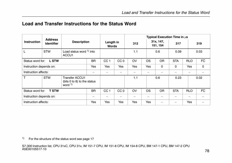
Load and Transfer Instructions for the Status Word
78S7-300 Instruction list, CPU 31xC, CPU 31x, IM 151-7 CPU, IM 151-8 CPU, IM 154-8 CPU, BM 147-1 CPU, BM 147-2 CPU A5E00105517-10
Load and Transfer Instructions for the Status Word
AddressTypical Execution Time in �s
InstructionAddressIdentifier Description Length in
Words312
31x, 147,151, 154
317 319
L STW Load status word 1) intoACCU1
1.1 0.6 0.09 0.03
Status word for: L STW BR CC 1 CC 0 OV OS OR STA RLO FC
Instruction depends on: Yes Yes Yes Yes Yes 0 0 Yes 0
Instruction affects: – – – – – – – – –
T STW Transfer ACCU1(bits 0 to 8) to the statusword 1)
1.1 0.6 0.23 0.02
Status word for: T STW BR CC 1 CC 0 OV OS OR STA RLO FC
Instruction depends on: – – – – – – – – –
Instruction affects: Yes Yes Yes Yes Yes – – Yes –
1) For the structure of the status word see page 17
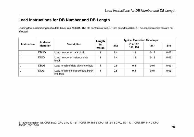
Load Instructions for DB Number and DB Length
79S7-300 Instruction list, CPU 31xC, CPU 31x, IM 151-7 CPU, IM 151-8 CPU, IM 154-8 CPU, BM 147-1 CPU, BM 147-2 CPU A5E00105517-10
Load Instructions for DB Number and DB Length
Loading the number/length of a data block into ACCU1. The old contents of ACCU1 are saved to ACCU2. The condition code bits are notaffected.
Address Length Typical Execution Time in �s
InstructionAddressIdentifier Description
Lengthin
Words312
31x, 147,151, 154
317 319
L DBNO Load number of data block 1 2.4 1.3 0.18 0.03
L DINO Load number of instance datablock
1 2.4 1.3 0.18 0.03
L DBLG Load length of data block into byte 1 0.5 0.3 0.04 0.03
L DILG Load length of instance data blockinto byte
1 0.5 0.3 0.04 0.03
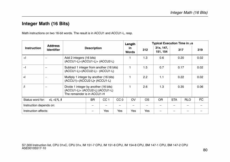
Integer Math (16 Bits)
80S7-300 Instruction list, CPU 31xC, CPU 31x, IM 151-7 CPU, IM 151-8 CPU, IM 154-8 CPU, BM 147-1 CPU, BM 147-2 CPU A5E00105517-10
Integer Math (16 Bits)
Math instructions on two 16-bit words. The result is in ACCU1 and ACCU1-L, resp.
AddressLength Typical Execution Time in �s
InstructionAddressIdentifier Description
Lengthin
Words312
31x, 147,151, 154
317 319
+I – Add 2 integers (16 bits)(ACCU1-L)=(ACCU1-L)+ (ACCU2-L)
1 1.3 0.6 0.20 0.02
–I – Subtract 1 integer from another (16 bits)(ACCU1-L)=(ACCU2-L)– (ACCU1-L)
1 1.5 0.7 0.17 0.02
*I – Multiply 1 integer by another (16 bits)(ACCU1)=(ACCU2-L)* (ACCU1-L)
1 2.2 1.1 0.22 0.02
/I – Divide 1 integer by another (16 bits)(ACCU1-L)= (ACCU2-L):(ACCU1-L)The remainder is in ACCU1-H
1 2.6 1.3 0.35 0.06
Status word for: +I, –I,*I, /I BR CC 1 CC 0 OV OS OR STA RLO FC
Instruction depends on: – – – – – – – – –
Instruction affects: – Yes Yes Yes Yes – – – –
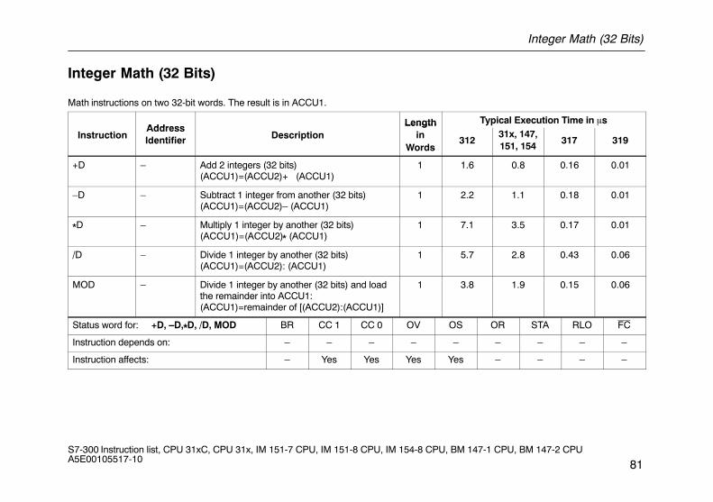
Integer Math (32 Bits)
81S7-300 Instruction list, CPU 31xC, CPU 31x, IM 151-7 CPU, IM 151-8 CPU, IM 154-8 CPU, BM 147-1 CPU, BM 147-2 CPU A5E00105517-10
Integer Math (32 Bits)
Math instructions on two 32-bit words. The result is in ACCU1.
AddressLength Typical Execution Time in �s
InstructionAddressIdentifier Description
Lengthin
Words312
31x, 147,151, 154
317 319
+D – Add 2 integers (32 bits)(ACCU1)=(ACCU2)+ (ACCU1)
1 1.6 0.8 0.16 0.01
–D – Subtract 1 integer from another (32 bits)(ACCU1)=(ACCU2)– (ACCU1)
1 2.2 1.1 0.18 0.01
*D – Multiply 1 integer by another (32 bits)(ACCU1)=(ACCU2)* (ACCU1)
1 7.1 3.5 0.17 0.01
/D – Divide 1 integer by another (32 bits)(ACCU1)=(ACCU2): (ACCU1)
1 5.7 2.8 0.43 0.06
MOD – Divide 1 integer by another (32 bits) and loadthe remainder into ACCU1:(ACCU1)=remainder of [(ACCU2):(ACCU1)]
1 3.8 1.9 0.15 0.06
Status word for: +D, –D,*D, /D, MOD BR CC 1 CC 0 OV OS OR STA RLO FC
Instruction depends on: – – – – – – – – –
Instruction affects: – Yes Yes Yes Yes – – – –
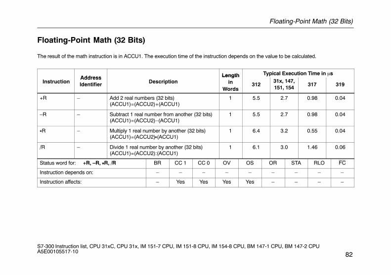
Floating-Point Math (32 Bits)
82S7-300 Instruction list, CPU 31xC, CPU 31x, IM 151-7 CPU, IM 151-8 CPU, IM 154-8 CPU, BM 147-1 CPU, BM 147-2 CPU A5E00105517-10
Floating-Point Math (32 Bits)
The result of the math instruction is in ACCU1. The execution time of the instruction depends on the value to be calculated.
Address Length Typical Execution Time in �s
InstructionAddressIdentifier Description
Lengthin
Words312
31x, 147,151, 154
317 319
+R – Add 2 real numbers (32 bits)(ACCU1)=(ACCU2)+(ACCU1)
1 5.5 2.7 0.98 0.04
–R – Subtract 1 real number from another (32 bits)(ACCU1)=(ACCU2)–(ACCU1)
1 5.5 2.7 0.98 0.04
*R – Multiply 1 real number by another (32 bits)(ACCU1)=(ACCU2)*(ACCU1)
1 6.4 3.2 0.55 0.04
/R – Divide 1 real number by another (32 bits)(ACCU1)=(ACCU2):(ACCU1)
1 6.1 3.0 1.46 0.06
Status word for: +R, –R, *R, /R BR CC 1 CC 0 OV OS OR STA RLO FC
Instruction depends on: – – – – – – – – –
Instruction affects: – Yes Yes Yes Yes – – – –
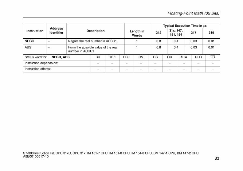
Floating-Point Math (32 Bits)
83S7-300 Instruction list, CPU 31xC, CPU 31x, IM 151-7 CPU, IM 151-8 CPU, IM 154-8 CPU, BM 147-1 CPU, BM 147-2 CPU A5E00105517-10
AddressTypical Execution Time in �s
InstructionAddressIdentifier Description Length in
Words312
31x, 147,151, 154
317 319
NEGR – Negate the real number in ACCU1 1 0.8 0.4 0.03 0.01
ABS – Form the absolute value of the realnumber in ACCU1
1 0.8 0.4 0.03 0.01
Status word for: NEGR, ABS BR CC 1 CC 0 OV OS OR STA RLO FC
Instruction depends on: – – – – – – – – –
Instruction affects: – – – – – – – – –
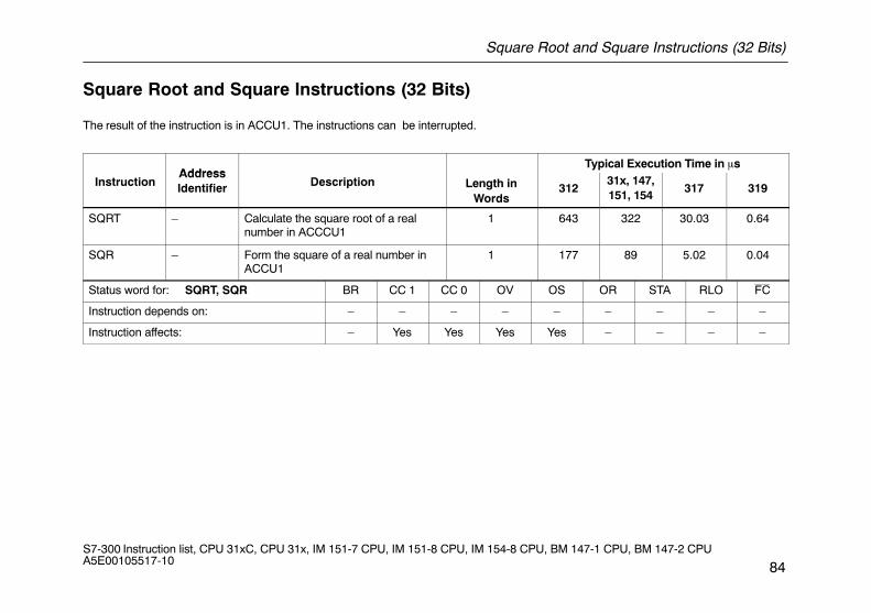
Square Root and Square Instructions (32 Bits)
84S7-300 Instruction list, CPU 31xC, CPU 31x, IM 151-7 CPU, IM 151-8 CPU, IM 154-8 CPU, BM 147-1 CPU, BM 147-2 CPU A5E00105517-10
Square Root and Square Instructions (32 Bits)
The result of the instruction is in ACCU1. The instructions can be interrupted.
AddressTypical Execution Time in �s
InstructionAddressIdentifier Description Length in
Words312
31x, 147,151, 154
317 319
SQRT – Calculate the square root of a realnumber in ACCCU1
1 643 322 30.03 0.64
SQR – Form the square of a real number inACCU1
1 177 89 5.02 0.04
Status word for: SQRT, SQR BR CC 1 CC 0 OV OS OR STA RLO FC
Instruction depends on: – – – – – – – – –
Instruction affects: – Yes Yes Yes Yes – – – –
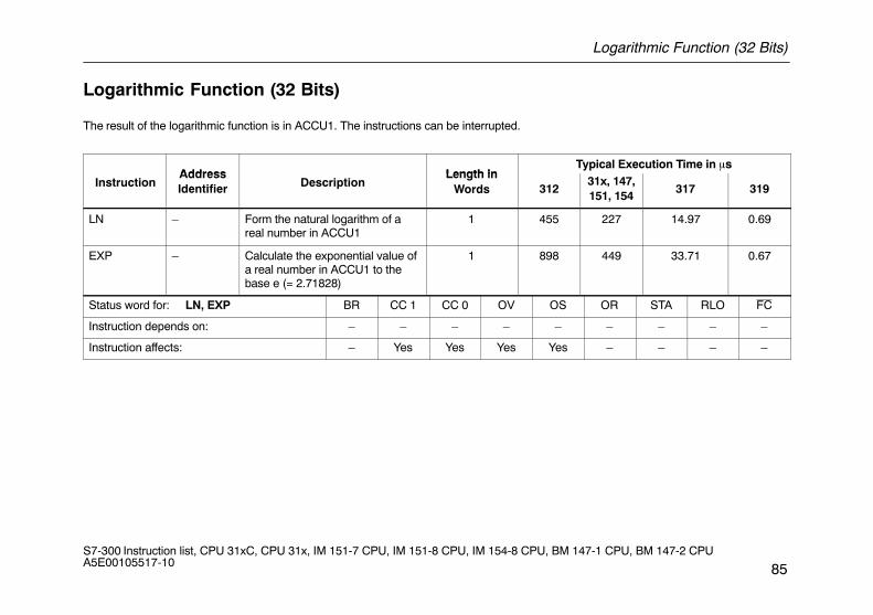
Logarithmic Function (32 Bits)
85S7-300 Instruction list, CPU 31xC, CPU 31x, IM 151-7 CPU, IM 151-8 CPU, IM 154-8 CPU, BM 147-1 CPU, BM 147-2 CPU A5E00105517-10
Logarithmic Function (32 Bits)
The result of the logarithmic function is in ACCU1. The instructions can be interrupted.
Address Length inTypical Execution Time in �s
InstructionAddressIdentifier Description
Length inWords 312
31x, 147,151, 154
317 319
LN – Form the natural logarithm of areal number in ACCU1
1 455 227 14.97 0.69
EXP – Calculate the exponential value ofa real number in ACCU1 to thebase e (= 2.71828)
1 898 449 33.71 0.67
Status word for: LN, EXP BR CC 1 CC 0 OV OS OR STA RLO FC
Instruction depends on: – – – – – – – – –
Instruction affects: – Yes Yes Yes Yes – – – –
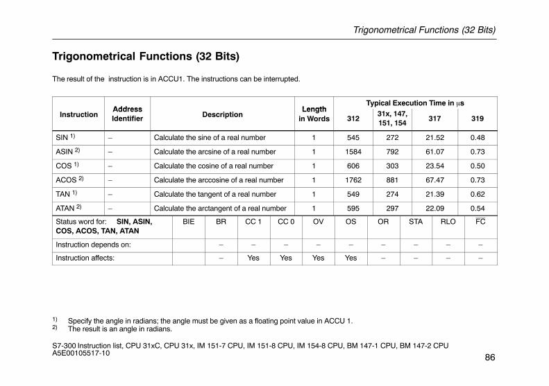
Trigonometrical Functions (32 Bits)
86S7-300 Instruction list, CPU 31xC, CPU 31x, IM 151-7 CPU, IM 151-8 CPU, IM 154-8 CPU, BM 147-1 CPU, BM 147-2 CPU A5E00105517-10
Trigonometrical Functions (32 Bits)
The result of the instruction is in ACCU1. The instructions can be interrupted.
Address LengthTypical Execution Time in �s
InstructionAddressIdentifier Description
Lengthin Words 312
31x, 147,151, 154
317 319
SIN 1) – Calculate the sine of a real number 1 545 272 21.52 0.48
ASIN 2) – Calculate the arcsine of a real number 1 1584 792 61.07 0.73
COS 1) – Calculate the cosine of a real number 1 606 303 23.54 0.50
ACOS 2) – Calculate the arccosine of a real number 1 1762 881 67.47 0.73
TAN 1) – Calculate the tangent of a real number 1 549 274 21.39 0.62
ATAN 2) – Calculate the arctangent of a real number 1 595 297 22.09 0.54
Status word for: SIN, ASIN,COS, ACOS, TAN, ATAN
BIE BR CC 1 CC 0 OV OS OR STA RLO FC
Instruction depends on: – – – – – – – – –
Instruction affects: – Yes Yes Yes Yes – – – –
1) Specify the angle in radians; the angle must be given as a floating point value in ACCU 1.2) The result is an angle in radians.
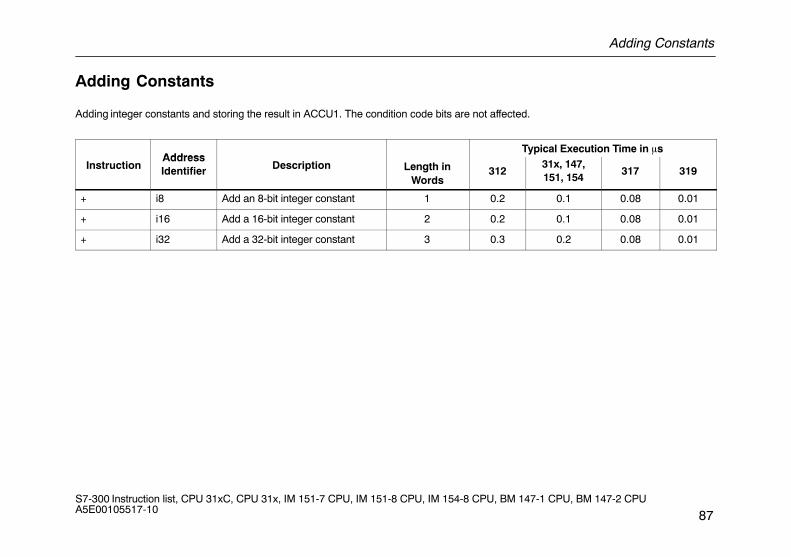
Adding Constants
87S7-300 Instruction list, CPU 31xC, CPU 31x, IM 151-7 CPU, IM 151-8 CPU, IM 154-8 CPU, BM 147-1 CPU, BM 147-2 CPU A5E00105517-10
Adding Constants
Adding integer constants and storing the result in ACCU1. The condition code bits are not affected.
AddressTypical Execution Time in �s
InstructionAddressIdentifier Description Length in
Words312
31x, 147,151, 154
317 319
+ i8 Add an 8-bit integer constant 1 0.2 0.1 0.08 0.01
+ i16 Add a 16-bit integer constant 2 0.2 0.1 0.08 0.01
+ i32 Add a 32-bit integer constant 3 0.3 0.2 0.08 0.01
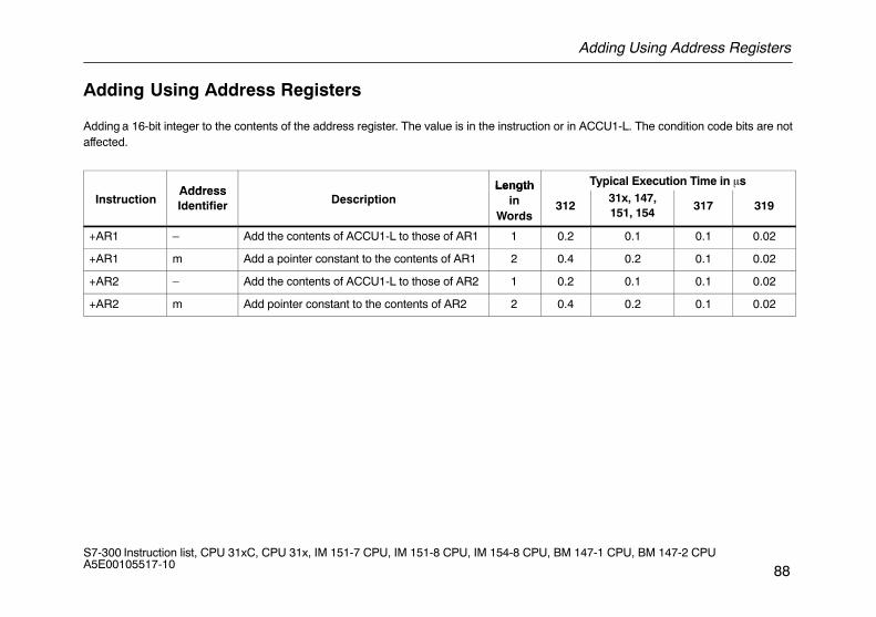
Adding Using Address Registers
88S7-300 Instruction list, CPU 31xC, CPU 31x, IM 151-7 CPU, IM 151-8 CPU, IM 154-8 CPU, BM 147-1 CPU, BM 147-2 CPU A5E00105517-10
Adding Using Address Registers
Adding a 16-bit integer to the contents of the address register. The value is in the instruction or in ACCU1-L. The condition code bits are notaffected.
Address Length Typical Execution Time in �s
InstructionAddressIdentifier Description
Lengthin
Words312
31x, 147,151, 154
317 319
+AR1 – Add the contents of ACCU1-L to those of AR1 1 0.2 0.1 0.1 0.02
+AR1 m Add a pointer constant to the contents of AR1 2 0.4 0.2 0.1 0.02
+AR2 – Add the contents of ACCU1-L to those of AR2 1 0.2 0.1 0.1 0.02
+AR2 m Add pointer constant to the contents of AR2 2 0.4 0.2 0.1 0.02
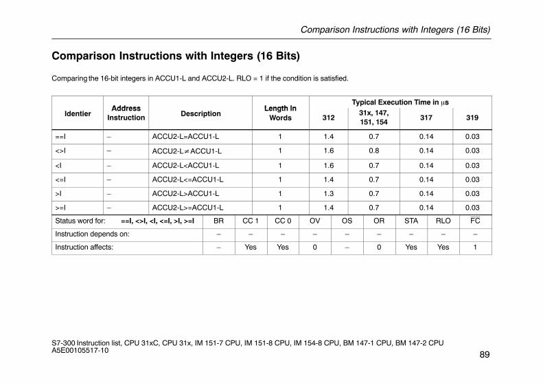
Comparison Instructions with Integers (16 Bits)
89S7-300 Instruction list, CPU 31xC, CPU 31x, IM 151-7 CPU, IM 151-8 CPU, IM 154-8 CPU, BM 147-1 CPU, BM 147-2 CPU A5E00105517-10
Comparison Instructions with Integers (16 Bits)
Comparing the 16-bit integers in ACCU1-L and ACCU2-L. RLO = 1 if the condition is satisfied.
Address Length inTypical Execution Time in �s
IdentierAddress
Instruction DescriptionLength in
Words 31231x, 147,151, 154
317 319
==I – ACCU2-L=ACCU1-L 1 1.4 0.7 0.14 0.03
<>I – ACCU2-L�ACCU1-L 1 1.6 0.8 0.14 0.03
<I – ACCU2-L<ACCU1-L 1 1.6 0.7 0.14 0.03
<=I – ACCU2-L<=ACCU1-L 1 1.4 0.7 0.14 0.03
>I – ACCU2-L>ACCU1-L 1 1.3 0.7 0.14 0.03
>=I – ACCU2-L>=ACCU1-L 1 1.4 0.7 0.14 0.03
Status word for: ==I, <>I, <I, <=I, >I, >=I BR CC 1 CC 0 OV OS OR STA RLO FC
Instruction depends on: – – – – – – – – –
Instruction affects: – Yes Yes 0 – 0 Yes Yes 1
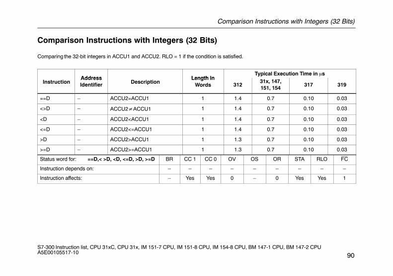
Comparison Instructions with Integers (32 Bits)
90S7-300 Instruction list, CPU 31xC, CPU 31x, IM 151-7 CPU, IM 151-8 CPU, IM 154-8 CPU, BM 147-1 CPU, BM 147-2 CPU A5E00105517-10
Comparison Instructions with Integers (32 Bits)
Comparing the 32-bit integers in ACCU1 and ACCU2. RLO = 1 if the condition is satisfied.
Address Length inTypical Execution Time in �s
InstructionAddressIdentifier Description
Length inWords 312
31x, 147,151, 154
317 319
==D – ACCU2=ACCU1 1 1.4 0.7 0.10 0.03
<>D – ACCU2�ACCU1 1 1.4 0.7 0.10 0.03
<D – ACCU2<ACCU1 1 1.4 0.7 0.10 0.03
<=D – ACCU2<=ACCU1 1 1.4 0.7 0.10 0.03
>D – ACCU2>ACCU1 1 1.3 0.7 0.10 0.03
>=D – ACCU2>=ACCU1 1 1.3 0.7 0.10 0.03
Status word for: ==D,< >D, <D, <=D, >D, >=D BR CC 1 CC 0 OV OS OR STA RLO FC
Instruction depends on: – – – – – – – – –
Instruction affects: – Yes Yes 0 – 0 Yes Yes 1
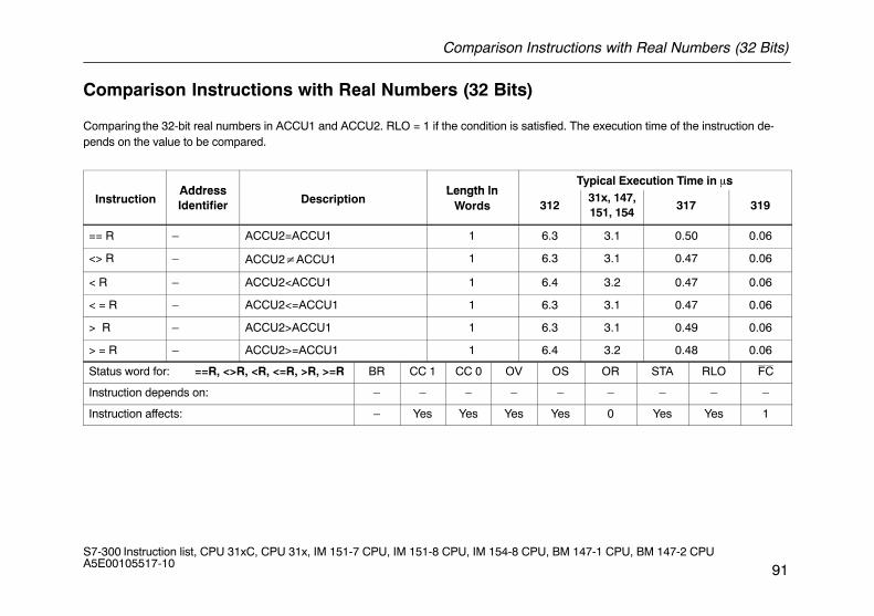
Comparison Instructions with Real Numbers (32 Bits)
91S7-300 Instruction list, CPU 31xC, CPU 31x, IM 151-7 CPU, IM 151-8 CPU, IM 154-8 CPU, BM 147-1 CPU, BM 147-2 CPU A5E00105517-10
Comparison Instructions with Real Numbers (32 Bits)
Comparing the 32-bit real numbers in ACCU1 and ACCU2. RLO = 1 if the condition is satisfied. The execution time of the instruction de-pends on the value to be compared.
Address Length inTypical Execution Time in �s
InstructionAddressIdentifier Description
Length inWords 312
31x, 147,151, 154
317 319
== R – ACCU2=ACCU1 1 6.3 3.1 0.50 0.06
<> R – ACCU2�ACCU1 1 6.3 3.1 0.47 0.06
< R – ACCU2<ACCU1 1 6.4 3.2 0.47 0.06
< = R – ACCU2<=ACCU1 1 6.3 3.1 0.47 0.06
> R – ACCU2>ACCU1 1 6.3 3.1 0.49 0.06
> = R – ACCU2>=ACCU1 1 6.4 3.2 0.48 0.06
Status word for: ==R, <>R, <R, <=R, >R, >=R BR CC 1 CC 0 OV OS OR STA RLO FC
Instruction depends on: – – – – – – – – –
Instruction affects: – Yes Yes Yes Yes 0 Yes Yes 1
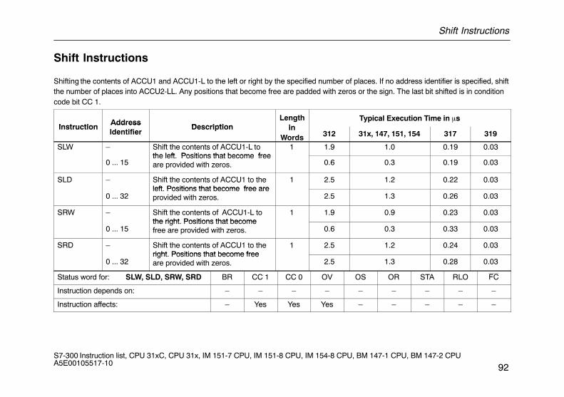
Shift Instructions
92S7-300 Instruction list, CPU 31xC, CPU 31x, IM 151-7 CPU, IM 151-8 CPU, IM 154-8 CPU, BM 147-1 CPU, BM 147-2 CPU A5E00105517-10
Shift Instructions
Shifting the contents of ACCU1 and ACCU1-L to the left or right by the specified number of places. If no address identifier is specified, shiftthe number of places into ACCU2-LL. Any positions that become free are padded with zeros or the sign. The last bit shifted is in conditioncode bit CC 1.
InstructionAddress
DescriptionLength
inTypical Execution Time in �s
InstructionAddressIdentifier
Description inWords 312 31x, 147, 151, 154 317 319
SLW – Shift the contents of ACCU1-L tothe left Positions that become free
1 1.9 1.0 0.19 0.03
0 ... 15the left. Positions that become freeare provided with zeros. 0.6 0.3 0.19 0.03
SLD – Shift the contents of ACCU1 to theleft Positions that become free are
1 2.5 1.2 0.22 0.03
0 ... 32left. Positions that become free areprovided with zeros. 2.5 1.3 0.26 0.03
SRW – Shift the contents of ACCU1-L tothe right Positions that become
1 1.9 0.9 0.23 0.03
0 ... 15the right. Positions that becomefree are provided with zeros. 0.6 0.3 0.33 0.03
SRD – Shift the contents of ACCU1 to theright Positions that become free
1 2.5 1.2 0.24 0.03
0 ... 32right. Positions that become freeare provided with zeros. 2.5 1.3 0.28 0.03
Status word for: SLW, SLD, SRW, SRD BR CC 1 CC 0 OV OS OR STA RLO FC
Instruction depends on: – – – – – – – – –
Instruction affects: – Yes Yes Yes – – – – –
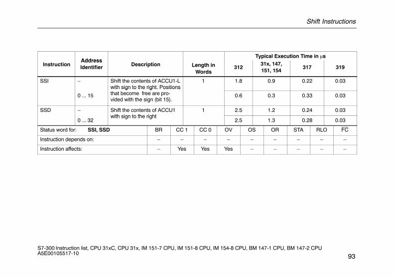
Shift Instructions
93S7-300 Instruction list, CPU 31xC, CPU 31x, IM 151-7 CPU, IM 151-8 CPU, IM 154-8 CPU, BM 147-1 CPU, BM 147-2 CPU A5E00105517-10
AddressTypical Execution Time in �s
InstructionAddressIdentifier Description Length in
Words312
31x, 147,151, 154
317 319
SSI – Shift the contents of ACCU1-Lwith sign to the right. Positions
1 1.8 0.9 0.22 0.03
0 ... 15
with sign to the right. Positionsthat become free are pro-vided with the sign (bit 15).
0.6 0.3 0.33 0.03
SSD – Shift the contents of ACCU1with sign to the right
1 2.5 1.2 0.24 0.03
0 ... 32with sign to the right
2.5 1.3 0.28 0.03
Status word for: SSI, SSD BR CC 1 CC 0 OV OS OR STA RLO FC
Instruction depends on: – – – – – – – – –
Instruction affects: – Yes Yes Yes – – – – –
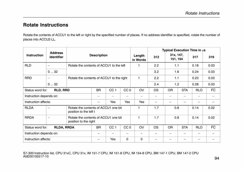
Rotate Instructions
94S7-300 Instruction list, CPU 31xC, CPU 31x, IM 151-7 CPU, IM 151-8 CPU, IM 154-8 CPU, BM 147-1 CPU, BM 147-2 CPU A5E00105517-10
Rotate Instructions
Rotate the contents of ACCU1 to the left or right by the specified number of places. If no address identifier is specified, rotate the number ofplaces into ACCU2-LL.
AddressTypical Execution Time in �s
InstructionAddressIdentifier Description Length
in Words312
31x, 147,151, 154
317 319
RLD – Rotate the contents of ACCU1 to the left 1 2.2 1.1 0.18 0.03
0 ... 32 3.2 1.6 0.24 0.03
RRD – Rotate the contents of ACCU1 to the right 1 2.2 1.1 0.23 0.03
0 ... 32 2.4 1.2 0.28 0.03
Status word for: RLD, RRD BR CC 1 CC 0 OV OS OR STA RLO FC
Instruction depends on: – – – – – – – – –
Instruction affects: – Yes Yes Yes – – – – –
RLDA – Rotate the contents of ACCU1 one bitposition to the left t
1 1.7 0.8 0.14 0.02
RRDA – Rotate the contents of ACCU1 one bitposition to the right
1 1.7 0.8 0.14 0.02
Status word for: RLDA, RRDA BR CC 1 CC 0 OV OS OR STA RLO FC
Instruction depends on: – – – – – – – – –
Instruction affects: – Yes 0 0 – – – – –
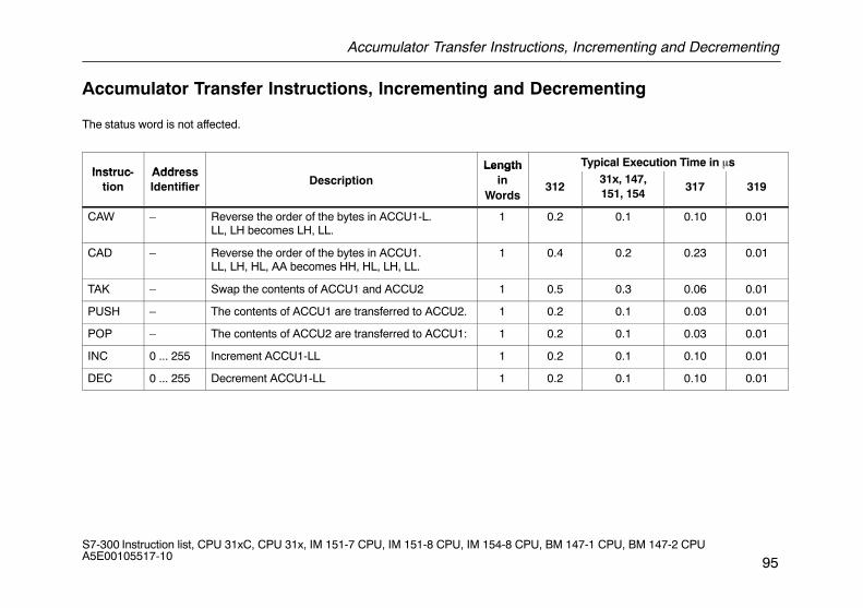
Accumulator Transfer Instructions, Incrementing and Decrementing
95S7-300 Instruction list, CPU 31xC, CPU 31x, IM 151-7 CPU, IM 151-8 CPU, IM 154-8 CPU, BM 147-1 CPU, BM 147-2 CPU A5E00105517-10
Accumulator Transfer Instructions, Incrementing and Decrementing
The status word is not affected.
Instruc AddressLength Typical Execution Time in �s
Instruc-tion
AddressIdentifier Description
Lengthin
Words312
31x, 147,151, 154
317 319
CAW – Reverse the order of the bytes in ACCU1-L.LL, LH becomes LH, LL.
1 0.2 0.1 0.10 0.01
CAD – Reverse the order of the bytes in ACCU1.LL, LH, HL, AA becomes HH, HL, LH, LL.
1 0.4 0.2 0.23 0.01
TAK – Swap the contents of ACCU1 and ACCU2 1 0.5 0.3 0.06 0.01
PUSH – The contents of ACCU1 are transferred to ACCU2. 1 0.2 0.1 0.03 0.01
POP – The contents of ACCU2 are transferred to ACCU1: 1 0.2 0.1 0.03 0.01
INC 0 ... 255 Increment ACCU1-LL 1 0.2 0.1 0.10 0.01
DEC 0 ... 255 Decrement ACCU1-LL 1 0.2 0.1 0.10 0.01
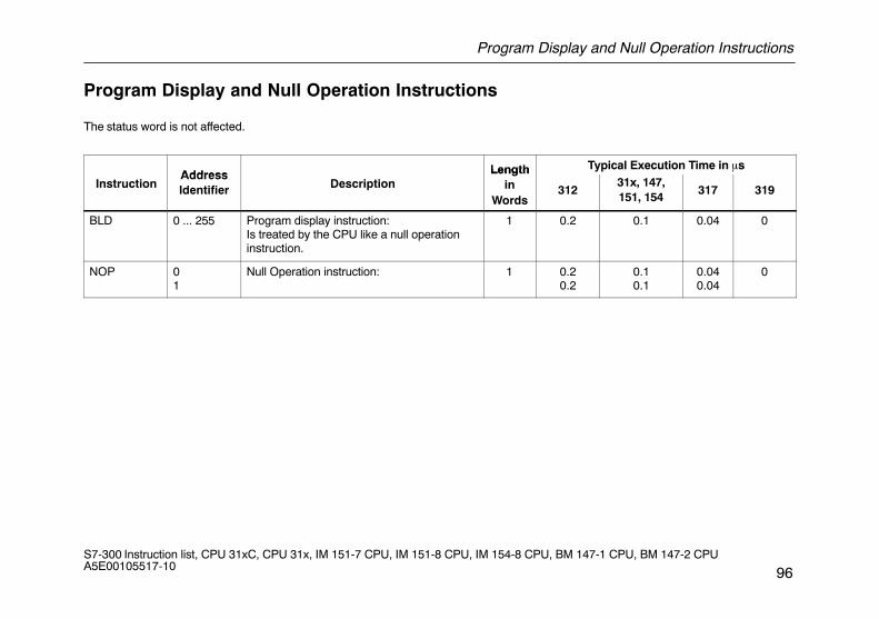
Program Display and Null Operation Instructions
96S7-300 Instruction list, CPU 31xC, CPU 31x, IM 151-7 CPU, IM 151-8 CPU, IM 154-8 CPU, BM 147-1 CPU, BM 147-2 CPU A5E00105517-10
Program Display and Null Operation Instructions
The status word is not affected.
Address Length Typical Execution Time in �s
InstructionAddressIdentifier Description
Lengthin
Words312
31x, 147,151, 154
317 319
BLD 0 ... 255 Program display instruction:Is treated by the CPU like a null operationinstruction.
1 0.2 0.1 0.04 0
NOP 01
Null Operation instruction: 1 0.20.2
0.10.1
0.040.04
0
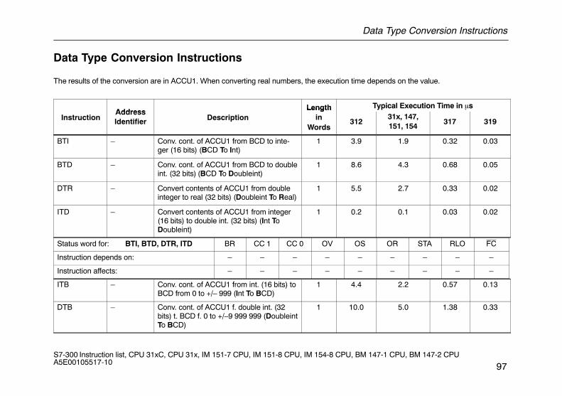
Data Type Conversion Instructions
97S7-300 Instruction list, CPU 31xC, CPU 31x, IM 151-7 CPU, IM 151-8 CPU, IM 154-8 CPU, BM 147-1 CPU, BM 147-2 CPU A5E00105517-10
Data Type Conversion Instructions
The results of the conversion are in ACCU1. When converting real numbers, the execution time depends on the value.
AddressLength Typical Execution Time in �s
InstructionAddressIdentifier Description
Lengthin
Words312
31x, 147,151, 154
317 319
BTI – Conv. cont. of ACCU1 from BCD to inte-ger (16 bits) (BCD To Int)
1 3.9 1.9 0.32 0.03
BTD – Conv. cont. of ACCU1 from BCD to doubleint. (32 bits) (BCD To Doubleint)
1 8.6 4.3 0.68 0.05
DTR – Convert contents of ACCU1 from doubleinteger to real (32 bits) (Doubleint To Real)
1 5.5 2.7 0.33 0.02
ITD – Convert contents of ACCU1 from integer(16 bits) to double int. (32 bits) (Int ToDoubleint)
1 0.2 0.1 0.03 0.02
Status word for: BTI, BTD, DTR, ITD BR CC 1 CC 0 OV OS OR STA RLO FC
Instruction depends on: – – – – – – – – –
Instruction affects: – – – – – – – – –
ITB – Conv. cont. of ACCU1 from int. (16 bits) toBCD from 0 to +/– 999 (Int To BCD)
1 4.4 2.2 0.57 0.13
DTB – Conv. cont. of ACCU1 f. double int. (32bits) t. BCD f. 0 to +/–9 999 999 (DoubleintTo BCD)
1 10.0 5.0 1.38 0.33
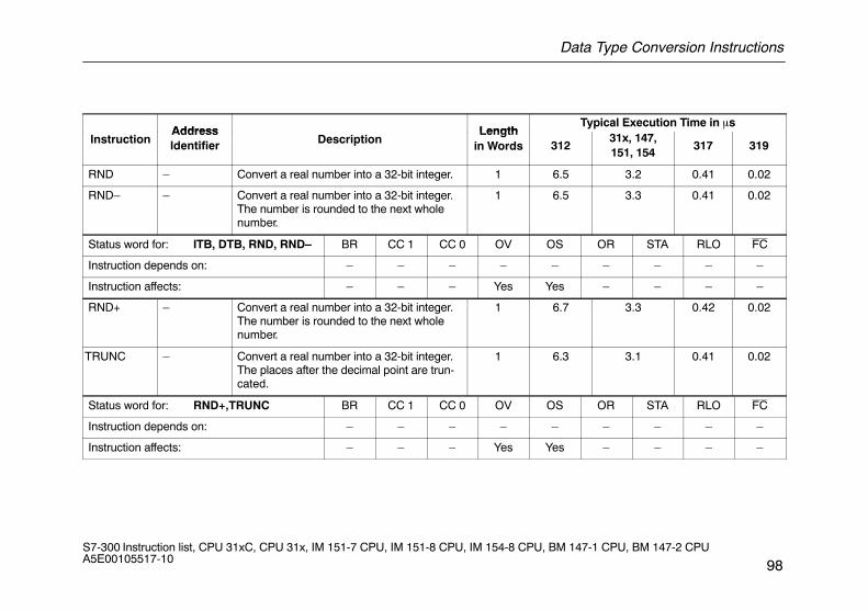
Data Type Conversion Instructions
98S7-300 Instruction list, CPU 31xC, CPU 31x, IM 151-7 CPU, IM 151-8 CPU, IM 154-8 CPU, BM 147-1 CPU, BM 147-2 CPU A5E00105517-10
Address LengthTypical Execution Time in �s
InstructionAddressIdentifier Description
Lengthin Words 312
31x, 147,151, 154
317 319
RND – Convert a real number into a 32-bit integer. 1 6.5 3.2 0.41 0.02
RND– – Convert a real number into a 32-bit integer.The number is rounded to the next wholenumber.
1 6.5 3.3 0.41 0.02
Status word for: ITB, DTB, RND, RND– BR CC 1 CC 0 OV OS OR STA RLO FC
Instruction depends on: – – – – – – – – –
Instruction affects: – – – Yes Yes – – – –
RND+ – Convert a real number into a 32-bit integer.The number is rounded to the next wholenumber.
1 6.7 3.3 0.42 0.02
TRUNC – Convert a real number into a 32-bit integer.The places after the decimal point are trun-cated.
1 6.3 3.1 0.41 0.02
Status word for: RND+,TRUNC BR CC 1 CC 0 OV OS OR STA RLO FC
Instruction depends on: – – – – – – – – –
Instruction affects: – – – Yes Yes – – – –

Forming the Ones and Twos Complements
99S7-300 Instruction list, CPU 31xC, CPU 31x, IM 151-7 CPU, IM 151-8 CPU, IM 154-8 CPU, BM 147-1 CPU, BM 147-2 CPU A5E00105517-10
Forming the Ones and Twos Complements
Address Length inTypical Execution Time in �s
InstructionAddressIdentifier Description
Length inWords 312
31x, 147,151, 154
317 319
INVI – Form the ones complement ofACCU1-L
1 0.2 0.1 0.05 0.01
INVD – Form the ones complement ofACCU1
1 0.2 0.1 0.08 0.01
Status word for: INVI, INVD BR CC 1 CC 0 OV OS OR STA RLO FC
Instruction depends on: – – – – – – – – –
Instruction affects: – – – – – – – – –
NEGI – Form the twos complement ofACCU1-L (integer)
1 1.4 0.7 0.19 0.01
NEGD – Form the twos complement ofACCU1 (double integer)
1 1.6 0.8 0.16 0.01
Status word for: NEGI, NEGD BR CC 1 CC 0 OV OS OR STA RLO FC
Instruction depends on: – – – – – – – – –
Instruction affects: – Yes Yes Yes Yes – – – –
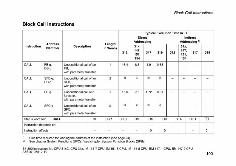
Block Call Instructions
100S7-300 Instruction list, CPU 31xC, CPU 31x, IM 151-7 CPU, IM 151-8 CPU, IM 154-8 CPU, BM 147-1 CPU, BM 147-2 CPU A5E00105517-10
Block Call Instructions
Typical Execution Time in �s
Address Length
DirectAddressing
IndirectAddressing 1)
InstructionAddressIdentifier Description
Lengthin Words
312
31x,147,151,154
317 319 312
31x,147,151,154
317 319
CALL FB q,DB q
Unconditional call of anFB,with parameter transfer
1 16.4 8.8 1.9 0.68 – – – –
CALL SFB q,DB q
Unconditional call of anSFB,with parameter transfer
2 2) 2) 2) 2) – – – –
CALL FC q Unconditional call of afunction,with parameter transfer
1 15.6 7.5 1.72 0.61 – – – –
CALL SFC q Unconditional call of anSFC,with parameter transfer
2 2) 2) 2) 2) – – – –
Status word for: CALL BR CC 1 CC 0 OV OS OR STA RLO FC
Instruction depends on: – – – – – – – – –
Instruction affects: – – – – 0 0 1 – 0
1) Plus time required for loading the address of the instruction (see page 24) 2) See chapter System Functions (SFCs)/ see chapter System Function Blocks (SFBs)
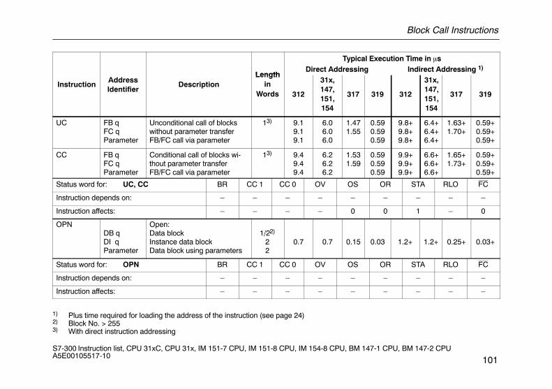
Block Call Instructions
101S7-300 Instruction list, CPU 31xC, CPU 31x, IM 151-7 CPU, IM 151-8 CPU, IM 154-8 CPU, BM 147-1 CPU, BM 147-2 CPU A5E00105517-10
Typical Execution Time in �s
LengthDirect Addressing Indirect Addressing 1)
InstructionAddressIdentifier
DescriptionLength
inWords 312
31x,147,151,154
317 319 312
31x,147,151,154
317 319
UC FB qFC qParameter
Unconditional call of blockswithout parameter transferFB/FC call via parameter
13) 9.19.19.1
6.06.06.0
1.471.55
0.590.590.59
9.8+9.8+9.8+
6.4+6.4+6.4+
1.63+1.70+
0.59+0.59+0.59+
CC FB qFC qParameter
Conditional call of blocks wi-thout parameter transferFB/FC call via parameter
13) 9.49.49.4
6.26.26.2
1.531.59
0.590.590.59
9.9+9.9+9.9+
6.6+6.6+6.6+
1.65+1.73+
0.59+0.59+0.59+
Status word for: UC, CC BR CC 1 CC 0 OV OS OR STA RLO FC
Instruction depends on: – – – – – – – – –
Instruction affects: – – – – 0 0 1 – 0
OPNDB qDI qParameter
Open:Data blockInstance data blockData block using parameters
1/22)
22
0.7 0.7 0.15 0.03 1.2+ 1.2+ 0.25+ 0.03+
Status word for: OPN BR CC 1 CC 0 OV OS OR STA RLO FC
Instruction depends on: – – – – – – – – –
Instruction affects: – – – – – – – – –
1) Plus time required for loading the address of the instruction (see page 24)2) Block No. > 2553) With direct instruction addressing
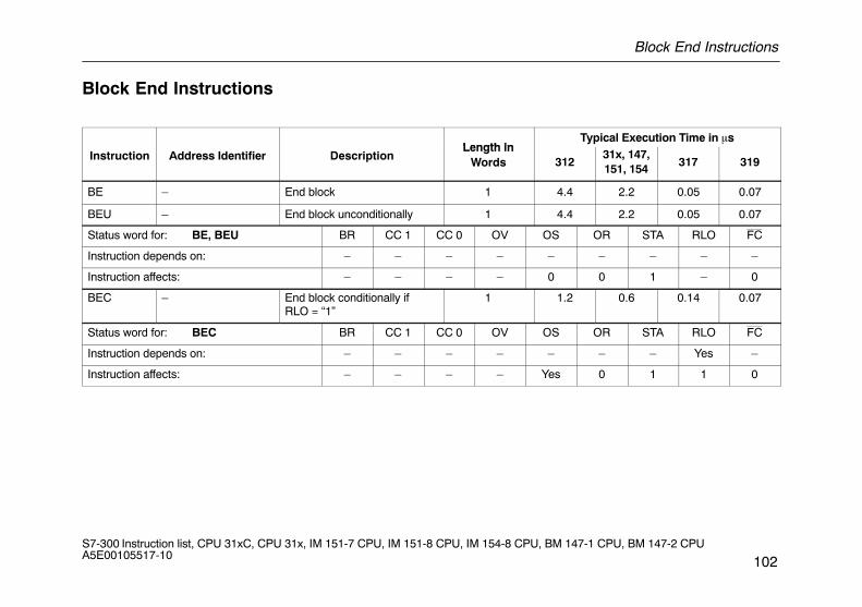
Block End Instructions
102S7-300 Instruction list, CPU 31xC, CPU 31x, IM 151-7 CPU, IM 151-8 CPU, IM 154-8 CPU, BM 147-1 CPU, BM 147-2 CPU A5E00105517-10
Block End Instructions
Length inTypical Execution Time in �s
Instruction Address Identifier DescriptionLength in
Words 31231x, 147,151, 154
317 319
BE – End block 1 4.4 2.2 0.05 0.07
BEU – End block unconditionally 1 4.4 2.2 0.05 0.07
Status word for: BE, BEU BR CC 1 CC 0 OV OS OR STA RLO FC
Instruction depends on: – – – – – – – – –
Instruction affects: – – – – 0 0 1 – 0
BEC – End block conditionally ifRLO = “1”
1 1.2 0.6 0.14 0.07
Status word for: BEC BR CC 1 CC 0 OV OS OR STA RLO FC
Instruction depends on: – – – – – – – Yes –
Instruction affects: – – – – Yes 0 1 1 0
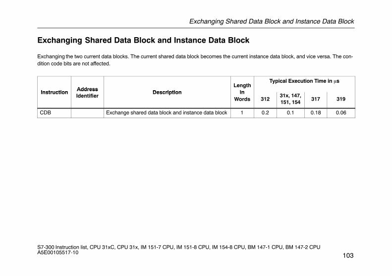
Exchanging Shared Data Block and Instance Data Block
103S7-300 Instruction list, CPU 31xC, CPU 31x, IM 151-7 CPU, IM 151-8 CPU, IM 154-8 CPU, BM 147-1 CPU, BM 147-2 CPU A5E00105517-10
Exchanging Shared Data Block and Instance Data Block
Exchanging the two current data blocks. The current shared data block becomes the current instance data block, and vice versa. The con-dition code bits are not affected.
InstructionAddress
DescriptionLength
in
Typical Execution Time in �s
InstructionAddressIdentifier
Description inWords 312
31x, 147,151, 154
317 319
CDB Exchange shared data block and instance data block 1 0.2 0.1 0.18 0.06
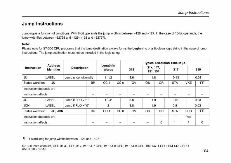
Jump Instructions
104S7-300 Instruction list, CPU 31xC, CPU 31x, IM 151-7 CPU, IM 151-8 CPU, IM 154-8 CPU, BM 147-1 CPU, BM 147-2 CPU A5E00105517-10
Jump Instructions
Jumping as a function of conditions. With 8-bit operands the jump width is between –128 and +127. In the case of 16-bit operands, thejump width lies between –32768 and –129 (+128 and +32767).
Note:Please note for S7-300 CPU programs that the jump destination always forms the beginning of a Boolean logic string in the case of jumpinstructions. The jump destination must not be included in the logic string.
Address Length inTypical Execution Time in �s
InstructionAddressIdentifier Description
Length inWords 312
31x, 147,151, 154
317 319
JU LABEL Jump unconditionally 1 1)/2 3.6 1.8 0.43 0.03
Status word for: JU BR CC 1 CC 0 OV OS OR STA VKE FC
Instruction depends on: – – – – – – – – –
Instruction affects: – – – – – – – – –
JC LABEL Jump if RLO = “1” 1 1)/2 3.8 1.9 0.51 0.03
JCN LABEL Jump if RLO = “0” 2 3.8 1.9 0.51 0.03
Status word for: JC, JCN BR CC 1 CC 0 OV OS OR STA RLO FC
Instruction depends on: – – – – – – – Yes –
Instruction affects: – – – – – 0 1 1 0
1) 1 word long for jump widths between –128 and +127
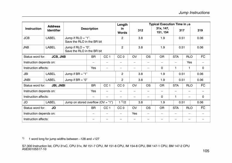
Jump Instructions
105S7-300 Instruction list, CPU 31xC, CPU 31x, IM 151-7 CPU, IM 151-8 CPU, IM 154-8 CPU, BM 147-1 CPU, BM 147-2 CPU A5E00105517-10
AddressLength Typical Execution Time in �s
InstructionAddressIdentifier Description
Lengthin
Words312
31x, 147,151, 154
317 319
JCB LABEL Jump if RLO = “1”.Save the RLO in the BR bit
2 3.8 1.9 0.51 0.06
JNB LABEL Jump if RLO = “0”.Save the RLO in the BR bit
2 3.8 1.9 0.51 0.06
Status word for: JCB, JNB BR CC 1 CC 0 OV OS OR STA RLO FC
Instruction depends on: – – – – – – – Yes –
Instruction affects: Yes – – – – 0 1 1 0
JBI LABEL Jump if BR = “1” 2 3.8 1.9 0.51 0.06
JNBI LABEL Jump if BR = “0” 2 3.8 1.9 0.51 0.06
Status word for: JBI, JNBI BR CC 1 CC 0 OV OS OR STA RLO FC
Instruction depends on: Yes – – – – – – – –
Instruction affects: – – – – – 0 1 – 0
JO LABEL Jump on stored overflow (OV = “1”) 1 1)/2 3.8 1.9 0.51 0.06
Status word for: JO BR CC 1 CC 0 OV OS OR STA RLO FC
Instruction depends on: – – – Yes – – – – –
Instruction affects: – – – – – – – – –
1) 1 word long for jump widths between –128 and +127
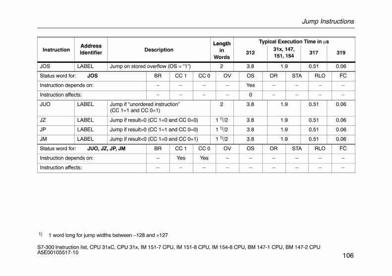
Jump Instructions
106S7-300 Instruction list, CPU 31xC, CPU 31x, IM 151-7 CPU, IM 151-8 CPU, IM 154-8 CPU, BM 147-1 CPU, BM 147-2 CPU A5E00105517-10
Address Length Typical Execution Time in �s
InstructionAddressIdentifier Description
Lengthin
Words312
31x, 147,151, 154
317 319
JOS LABEL Jump on stored overflow (OS = “1”) 2 3.8 1.9 0.51 0.06
Status word for: JOS BR CC 1 CC 0 OV OS OR STA RLO FC
Instruction depends on: – – – – Yes – – – –
Instruction affects: – – – – 0 – – – –
JUO LABEL Jump if “unordered instruction”(CC 1=1 and CC 0=1)
2 3.8 1.9 0.51 0.06
JZ LABEL Jump if result=0 (CC 1=0 and CC 0=0) 1 1)/2 3.8 1.9 0.51 0.06
JP LABEL Jump if result>0 (CC 1=1 and CC 0=0) 1 1)/2 3.8 1.9 0.51 0.06
JM LABEL Jump if result<0 (CC 1=0 and CC 0=1) 1 1)/2 3.8 1.9 0.51 0.06
Status word for: JUO, JZ, JP, JM BR CC 1 CC 0 OV OS OR STA RLO FC
Instruction depends on: – Yes Yes – – – – – –
Instruction affects: – – – – – – – – –
1) 1 word long for jump widths between –128 and +127
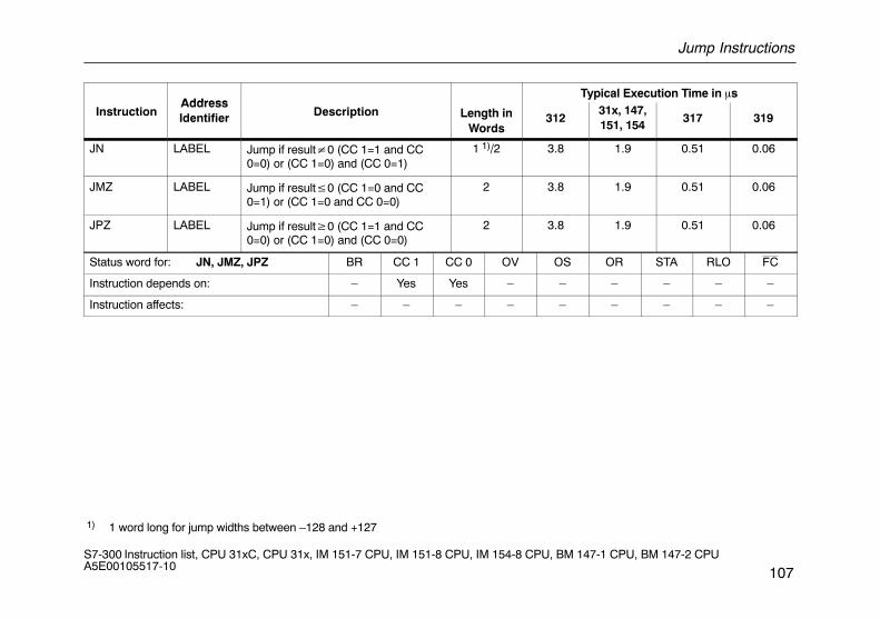
Jump Instructions
107S7-300 Instruction list, CPU 31xC, CPU 31x, IM 151-7 CPU, IM 151-8 CPU, IM 154-8 CPU, BM 147-1 CPU, BM 147-2 CPU A5E00105517-10
AddressTypical Execution Time in �s
InstructionAddressIdentifier Description Length in
Words312
31x, 147,151, 154
317 319
JN LABEL Jump if result�0 (CC 1=1 and CC0=0) or (CC 1=0) and (CC 0=1)
1 1)/2 3.8 1.9 0.51 0.06
JMZ LABEL Jump if result�0 (CC 1=0 and CC0=1) or (CC 1=0 and CC 0=0)
2 3.8 1.9 0.51 0.06
JPZ LABEL Jump if result�0 (CC 1=1 and CC0=0) or (CC 1=0) and (CC 0=0)
2 3.8 1.9 0.51 0.06
Status word for: JN, JMZ, JPZ BR CC 1 CC 0 OV OS OR STA RLO FC
Instruction depends on: – Yes Yes – – – – – –
Instruction affects: – – – – – – – – –
1) 1 word long for jump widths between –128 and +127
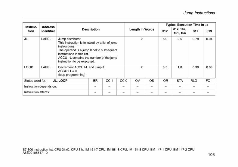
Jump Instructions
108S7-300 Instruction list, CPU 31xC, CPU 31x, IM 151-7 CPU, IM 151-8 CPU, IM 154-8 CPU, BM 147-1 CPU, BM 147-2 CPU A5E00105517-10
Instruc- AddressTypical Execution Time in �s
Instruc-tion
AddressIdentifier Description Length in Words 312
31x, 147,151, 154
317 319
JL LABEL Jump distributorThis instruction is followed by a list of jumpinstructions.The operand is a jump label to subsequentinstructions in this list.ACCU1-L contains the number of the jumpinstruction to be executed.
2 5.0 2.5 0.78 0.04
LOOP LABEL Decrement ACCU1-L and jump ifACCU1-L�0(loop programming)
2 3.5 1.8 0.30 0.03
Status word for: JL, LOOP BR CC 1 CC 0 OV OS OR STA RLO FC
Instruction depends on: – – – – – – – – –
Instruction affects: – – – – – – – – –
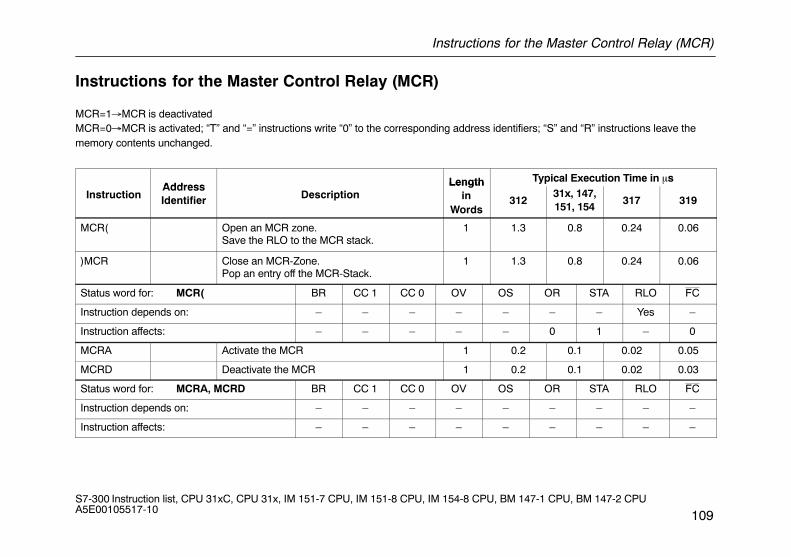
Instructions for the Master Control Relay (MCR)
109S7-300 Instruction list, CPU 31xC, CPU 31x, IM 151-7 CPU, IM 151-8 CPU, IM 154-8 CPU, BM 147-1 CPU, BM 147-2 CPU A5E00105517-10
Instructions for the Master Control Relay (MCR)
MCR=1�MCR is deactivatedMCR=0�MCR is activated; “T” and “=” instructions write “0” to the corresponding address identifiers; “S” and “R” instructions leave thememory contents unchanged.
Address Length Typical Execution Time in �s
InstructionAddressIdentifier Description
Lengthin
Words312
31x, 147,151, 154
317 319
MCR( Open an MCR zone.Save the RLO to the MCR stack.
1 1.3 0.8 0.24 0.06
)MCR Close an MCR-Zone.Pop an entry off the MCR-Stack.
1 1.3 0.8 0.24 0.06
Status word for: MCR( BR CC 1 CC 0 OV OS OR STA RLO FC
Instruction depends on: – – – – – – – Yes –
Instruction affects: – – – – – 0 1 – 0
MCRA Activate the MCR 1 0.2 0.1 0.02 0.05
MCRD Deactivate the MCR 1 0.2 0.1 0.02 0.03
Status word for: MCRA, MCRD BR CC 1 CC 0 OV OS OR STA RLO FC
Instruction depends on: – – – – – – – – –
Instruction affects: – – – – – – – – –
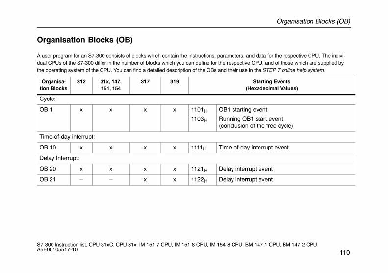
Organisation Blocks (OB)
110S7-300 Instruction list, CPU 31xC, CPU 31x, IM 151-7 CPU, IM 151-8 CPU, IM 154-8 CPU, BM 147-1 CPU, BM 147-2 CPU A5E00105517-10
Organisation Blocks (OB)
A user program for an S7-300 consists of blocks which contain the instructions, parameters, and data for the respective CPU. The indivi-dual CPUs of the S7-300 differ in the number of blocks which you can define for the respective CPU, and of those which are supplied bythe operating system of the CPU. You can find a detailed description of the OBs and their use in the STEP 7 online help system.
Organisa-tion Blocks
312 31x, 147,151, 154
317 319 Starting Events(Hexadecimal Values)
Cycle:
OB 1 x x x x 1101H
1103H
OB1 starting event
Running OB1 start event (conclusion of the free cycle)
Time-of-day interrupt:
OB 10 x x x x 1111H Time-of-day interrupt event
Delay Interrupt:
OB 20 x x x x 1121H Delay interrupt event
OB 21 – – x x 1122H Delay interrupt event
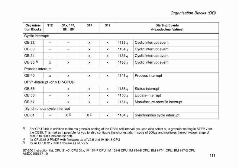
Organisation Blocks (OB)
111S7-300 Instruction list, CPU 31xC, CPU 31x, IM 151-7 CPU, IM 151-8 CPU, IM 154-8 CPU, BM 147-1 CPU, BM 147-2 CPU A5E00105517-10
Organisa-tion Blocks
Starting Events(Hexadecimal Values)
31931731x, 147,151, 154
312
Cyclic interrupt:
OB 32 – – x x 1133H Cyclic interrupt event
OB 33 – – x x 1134H Cyclic interrupt event
OB 34 – – x x 1135H Cyclic interrupt event
OB 35 1) x x x x 1136H Cyclic interrupt event
Process interrupt:
OB 40 x x x x 1141H Process interrupt
DPV1-Interrupt (only DP-CPUs)
OB 55 – x x x 1155H Status interrupt
OB 56 – x x x 1156H Update-interrupt
OB 57 – x x x 1157H Manufacture-specific interrupt
Synchronous cycle interrupt
OB 61 – X 2) X 3) x 1164H Synchronous cycle interrupt
1) For CPU 319: in addition to the ms granular setting of the OB35 call interval, you can also select a μs granular setting in STEP 7 for the OB35. This makes it possible for you to also configure the shortest alarm cycle of 500μs and multiples thereof (value range of 500μs to 60000ms can be set).
2) for CPU315-2 PN/DP with firmware as of V2.5 and IM154-8 CPU3) for all CPUs 317 with firmware as of V2.5
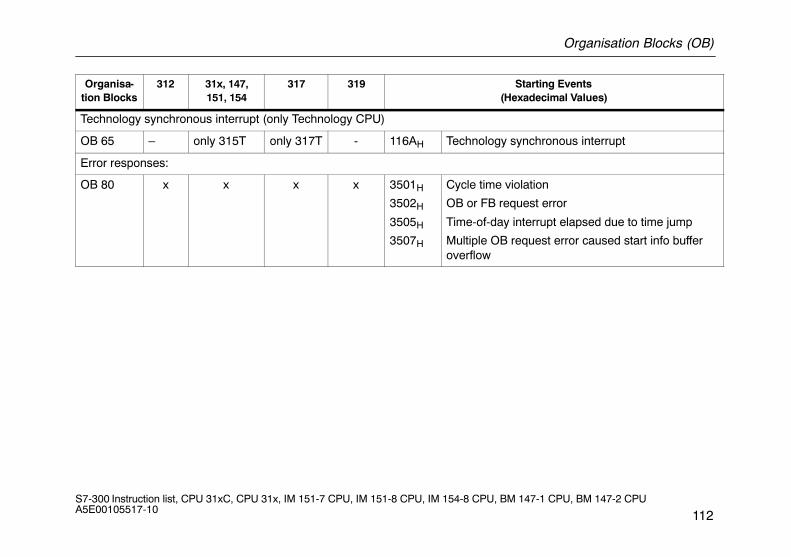
Organisation Blocks (OB)
112S7-300 Instruction list, CPU 31xC, CPU 31x, IM 151-7 CPU, IM 151-8 CPU, IM 154-8 CPU, BM 147-1 CPU, BM 147-2 CPU A5E00105517-10
Organisa-tion Blocks
Starting Events(Hexadecimal Values)
31931731x, 147,151, 154
312
Technology synchronous interrupt (only Technology CPU)
OB 65 – only 315T only 317T - 116AH Technology synchronous interrupt
Error responses:
OB 80 x x x x 3501H
3502H
3505H
3507H
Cycle time violation
OB or FB request error
Time-of-day interrupt elapsed due to time jump
Multiple OB request error caused start info bufferoverflow
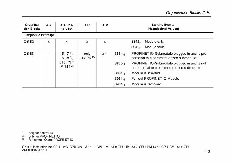
Organisation Blocks (OB)
113S7-300 Instruction list, CPU 31xC, CPU 31x, IM 151-7 CPU, IM 151-8 CPU, IM 154-8 CPU, BM 147-1 CPU, BM 147-2 CPU A5E00105517-10
Organisa-tion Blocks
Starting Events(Hexadecimal Values)
31931731x, 147,151, 154
312
Diagnostic interrupt:
OB 82 x x x x 3842H Module o. k.
3942H Module fault
OB 83 – 151-7 1),151-8 3),315 PN2)
IM 154 3)
only317 PN 2)
x 2) 3854H
3855H
3861H
3951H
3961H
PROFINET IO-Submodule plugged in and is pro-portional to a parameteterized submodule
PROFINET IO-Submodule plugged in and is notproportional to a parameteterized submodule
Module is inserted
Pull out PROFINET IO-Module
Module is removed
1) only for central IO2) only for PROFINET IO3) for central IO and PROFINET IO
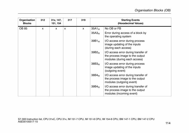
Organisation Blocks (OB)
114S7-300 Instruction list, CPU 31xC, CPU 31x, IM 151-7 CPU, IM 151-8 CPU, IM 154-8 CPU, BM 147-1 CPU, BM 147-2 CPU A5E00105517-10
OrganisationBlocks
312 31x, 147,151, 154
317 319 Starting Events(Hexadecimal Values)
OB 85 x x x x 35A1H
35A3H
39B1H
39B2H
38B3H
38B4H
39B4H
No OB or FB
Error during access of a block bythe operating system
I/O access error during processimage updating of the inputs(during each access)
I/O access error during transfer ofthe process image to the outputmodules (during each access)
I/O access error during processimage updating of the inputs(outgoing event)
I/O access error during transfer ofthe process image to the outputmodules (outgoing event)
I/O access error during transfer ofthe process image to the outputmodules (incoming event)
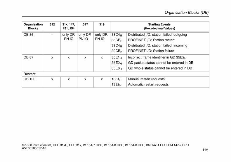
Organisation Blocks (OB)
115S7-300 Instruction list, CPU 31xC, CPU 31x, IM 151-7 CPU, IM 151-8 CPU, IM 154-8 CPU, BM 147-1 CPU, BM 147-2 CPU A5E00105517-10
OrganisationBlocks
Starting Events(Hexadecimal Values)
31931731x, 147,151, 154
312
OB 86 – only DP,PN IO
only DP,PN IO
only DP,PN IO
38C4H
38CBH
39C4H
39CBH
Distributed I/O: station failed, outgoing
PROFINET I/O: Station restart
Distributed I/O: station failed, incoming
PROFINET I/O: Station failure
OB 87 x x x x 35E1H
35E2H
35E6H
Incorrect frame identifier in GD 35E2H
GD packet status cannot be entered in DB
GD whole status cannot be entered in DB
Restart:
OB 100 x x x x 1381H
1382H
Manual restart requests
Automatic restart requests
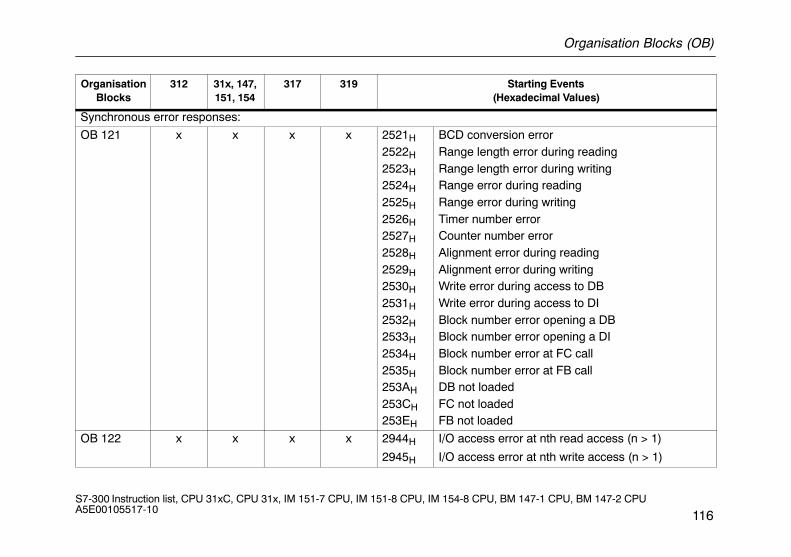
Organisation Blocks (OB)
116S7-300 Instruction list, CPU 31xC, CPU 31x, IM 151-7 CPU, IM 151-8 CPU, IM 154-8 CPU, BM 147-1 CPU, BM 147-2 CPU A5E00105517-10
OrganisationBlocks
Starting Events(Hexadecimal Values)
31931731x, 147,151, 154
312
Synchronous error responses:
OB 121 x x x x 2521H
2522H
2523H
2524H
2525H
2526H
2527H
2528H
2529H
2530H
2531H
2532H
2533H
2534H
2535H
253AH
253CH
253EH
BCD conversion errorRange length error during readingRange length error during writingRange error during readingRange error during writingTimer number errorCounter number errorAlignment error during readingAlignment error during writingWrite error during access to DBWrite error during access to DIBlock number error opening a DBBlock number error opening a DIBlock number error at FC callBlock number error at FB callDB not loadedFC not loadedFB not loaded
OB 122 x x x x 2944H
2945H
I/O access error at nth read access (n > 1)
I/O access error at nth write access (n > 1)
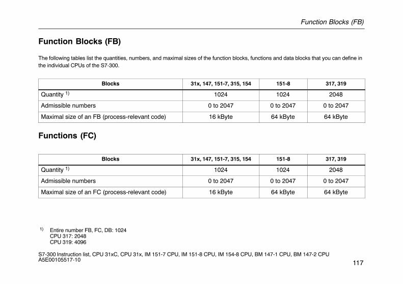
Function Blocks (FB)
117S7-300 Instruction list, CPU 31xC, CPU 31x, IM 151-7 CPU, IM 151-8 CPU, IM 154-8 CPU, BM 147-1 CPU, BM 147-2 CPU A5E00105517-10
Function Blocks (FB)
The following tables list the quantities, numbers, and maximal sizes of the function blocks, functions and data blocks that you can define inthe individual CPUs of the S7-300.
Blocks 31x, 147, 151-7, 315, 154 151-8 317, 319
Quantity 1) 1024 1024 2048
Admissible numbers 0 to 2047 0 to 2047 0 to 2047
Maximal size of an FB (process-relevant code) 16 kByte 64 kByte 64 kByte
Functions (FC)
Blocks 31x, 147, 151-7, 315, 154 151-8 317, 319
Quantity 1) 1024 1024 2048
Admissible numbers 0 to 2047 0 to 2047 0 to 2047
Maximal size of an FC (process-relevant code) 16 kByte 64 kByte 64 kByte
1) Entire number FB, FC, DB: 1024CPU 317: 2048CPU 319: 4096
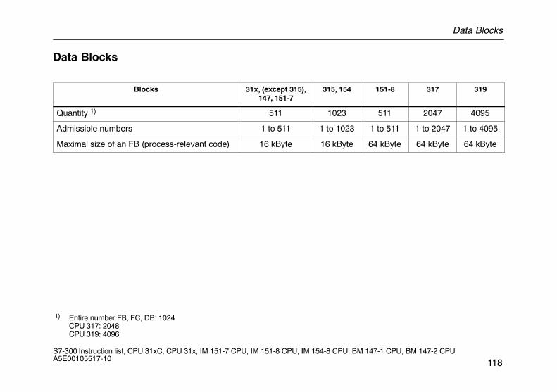
Data Blocks
118S7-300 Instruction list, CPU 31xC, CPU 31x, IM 151-7 CPU, IM 151-8 CPU, IM 154-8 CPU, BM 147-1 CPU, BM 147-2 CPU A5E00105517-10
Data Blocks
Blocks 31x, (except 315),147, 151-7
315, 154 151-8 317 319
Quantity 1) 511 1023 511 2047 4095
Admissible numbers 1 to 511 1 to 1023 1 to 511 1 to 2047 1 to 4095
Maximal size of an FB (process-relevant code) 16 kByte 16 kByte 64 kByte 64 kByte 64 kByte
1) Entire number FB, FC, DB: 1024CPU 317: 2048CPU 319: 4096
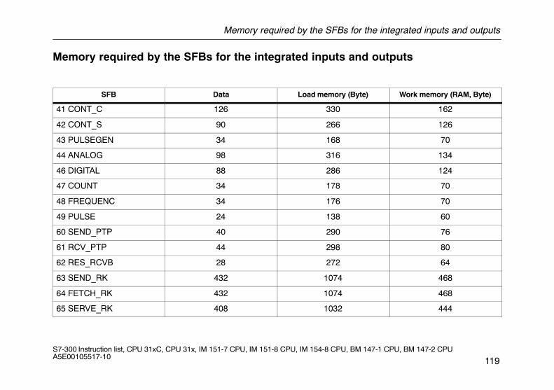
Memory required by the SFBs for the integrated inputs and outputs
119S7-300 Instruction list, CPU 31xC, CPU 31x, IM 151-7 CPU, IM 151-8 CPU, IM 154-8 CPU, BM 147-1 CPU, BM 147-2 CPU A5E00105517-10
Memory required by the SFBs for the integrated inputs and outputs
SFB Data Load memory (Byte) Work memory (RAM, Byte)
41 CONT_C 126 330 162
42 CONT_S 90 266 126
43 PULSEGEN 34 168 70
44 ANALOG 98 316 134
46 DIGITAL 88 286 124
47 COUNT 34 178 70
48 FREQUENC 34 176 70
49 PULSE 24 138 60
60 SEND_PTP 40 290 76
61 RCV_PTP 44 298 80
62 RES_RCVB 28 272 64
63 SEND_RK 432 1074 468
64 FETCH_RK 432 1074 468
65 SERVE_RK 408 1032 444
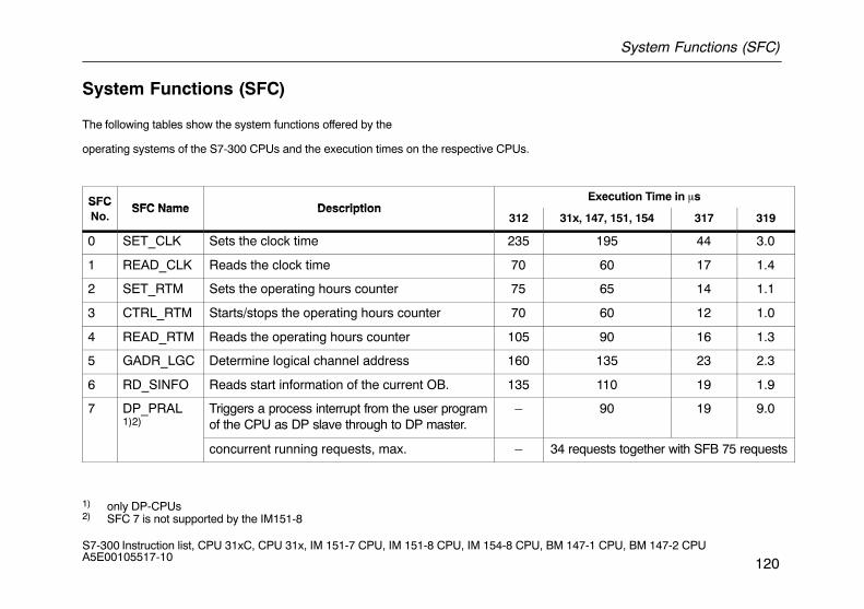
System Functions (SFC)
120S7-300 Instruction list, CPU 31xC, CPU 31x, IM 151-7 CPU, IM 151-8 CPU, IM 154-8 CPU, BM 147-1 CPU, BM 147-2 CPU A5E00105517-10
System Functions (SFC)
The following tables show the system functions offered by the
operating systems of the S7-300 CPUs and the execution times on the respective CPUs.
SFCSFC Name Description
Execution Time in �sSFCNo.
SFC Name Description312 31x, 147, 151, 154 317 319
0 SET_CLK Sets the clock time 235 195 44 3.0
1 READ_CLK Reads the clock time 70 60 17 1.4
2 SET_RTM Sets the operating hours counter 75 65 14 1.1
3 CTRL_RTM Starts/stops the operating hours counter 70 60 12 1.0
4 READ_RTM Reads the operating hours counter 105 90 16 1.3
5 GADR_LGC Determine logical channel address 160 135 23 2.3
6 RD_SINFO Reads start information of the current OB. 135 110 19 1.9
7 DP_PRAL1)2)
Triggers a process interrupt from the user programof the CPU as DP slave through to DP master.
– 90 19 9.0
concurrent running requests, max. – 34 requests together with SFB 75 requests
1) only DP-CPUs2) SFC 7 is not supported by the IM151-8
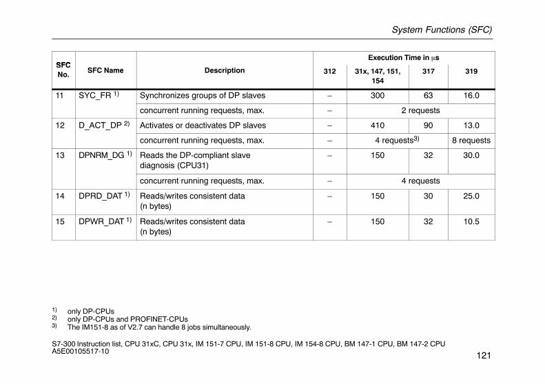
System Functions (SFC)
121S7-300 Instruction list, CPU 31xC, CPU 31x, IM 151-7 CPU, IM 151-8 CPU, IM 154-8 CPU, BM 147-1 CPU, BM 147-2 CPU A5E00105517-10
SFCExecution Time in �s
SFCNo. SFC Name Description 312 31x, 147, 151,
154317 319
11 SYC_FR 1) Synchronizes groups of DP slaves – 300 63 16.0
concurrent running requests, max. – 2 requests
12 D_ACT_DP 2) Activates or deactivates DP slaves – 410 90 13.0
concurrent running requests, max. – 4 requests3) 8 requests
13 DPNRM_DG 1) Reads the DP-compliant slave diagnosis (CPU31)
– 150 32 30.0
concurrent running requests, max. – 4 requests
14 DPRD_DAT 1) Reads/writes consistent data(n bytes)
– 150 30 25.0
15 DPWR_DAT 1) Reads/writes consistent data(n bytes)
– 150 32 10.5
1) only DP-CPUs2) only DP-CPUs and PROFINET-CPUs3) The IM151-8 as of V2.7 can handle 8 jobs simultaneously.
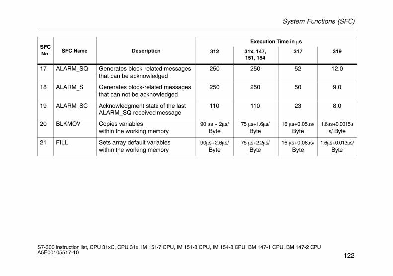
System Functions (SFC)
122S7-300 Instruction list, CPU 31xC, CPU 31x, IM 151-7 CPU, IM 151-8 CPU, IM 154-8 CPU, BM 147-1 CPU, BM 147-2 CPU A5E00105517-10
SFCExecution Time in �s
SFCNo. SFC Name Description 312 31x, 147,
151, 154317 319
17 ALARM_SQ Generates block-related messagesthat can be acknowledged
250 250 52 12.0
18 ALARM_S Generates block-related messagesthat can not be acknowledged
250 250 50 9.0
19 ALARM_SC Acknowledgment state of the lastALARM_SQ received message
110 110 23 8.0
20 BLKMOV Copies variableswithin the working memory
90 �s + 2�s/Byte
75 �s+1.6�s/Byte
16 �s+0.05�s/Byte
1.6�s+0.0015�s/ Byte
21 FILL Sets array default variableswithin the working memory
90�s+2.6�s/Byte
75 �s+2.2�s/Byte
16 �s+0.08�s/Byte
1.6�s+0.013�s/Byte
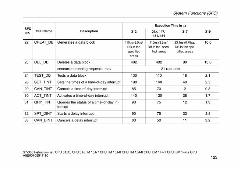
System Functions (SFC)
123S7-300 Instruction list, CPU 31xC, CPU 31x, IM 151-7 CPU, IM 151-8 CPU, IM 154-8 CPU, BM 147-1 CPU, BM 147-2 CPU A5E00105517-10
SFCExecution Time in �s
SFCNo. SFC Name Description 312 31x, 147,
151, 154317 319
22 CREAT_DB Generates a data block 110�s+3.5�s/DB in thespecified
areas
110�s+3.5�s/ DB in the speci-
fied areas
23.1�s+0.75�s/DB in the spe-
cified areas
10.0
23 DEL_DB Deletes a data block 402 402 80 13.0
concurrent running requests, max. 21 requests
24 TEST_DB Tests a data block 130 110 18 2.1
28 SET_TINT Sets the times of a time-of-day interrupt 190 160 40 2.5
29 CAN_TINT Cancels a time-of-day interrupt 85 70 2 0.8
30 ACT_TINT Activates a time-of-day interrupt 140 120 28 1.7
31 QRY_TINT Queries the status of a time–of-day in-terrupt
90 75 12 1.3
32 SRT_DINT Starts a delay interrupt 90 75 22 3.8
33 CAN_DINT Cancels a delay interrupt 60 50 11 3.2
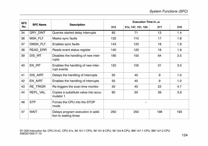
System Functions (SFC)
124S7-300 Instruction list, CPU 31xC, CPU 31x, IM 151-7 CPU, IM 151-8 CPU, IM 154-8 CPU, BM 147-1 CPU, BM 147-2 CPU A5E00105517-10
SFCSFC Name Description
Execution Time in �sSFCNo.
SFC Name Description312 31x, 147, 151, 154 317 319
34 QRY_DINT Queries started delay interrupts 85 71 13 1.4
36 MSK_FLT Masks sync faults 132 110 17 1.8
37 DMSK_FLT Enables sync faults 143 120 18 1.9
38 READ_ERR Reads event status register 140 120 18 1.9
39 DIS_IRT Disables the handling of new inter-rupts
180 155 64 3.5
40 EN_IRT Enables the handling of new inter-rupt events
125 105 31 3.0
41 DIS_AIRT Delays the handling of interrupts 50 45 9 1.0
42 EN_AIRT Enables the handling of interrupts 55 45 9 1.0
43 RE_TRIGR Re-triggers the scan time monitor 50 40 23 4.7
44 REPL_VAL Copies a substitute value into accu-mulator 1
60 50 39 3.9
46 STP Forces the CPU into the STOPmode
–
47 WAIT Delays program execution in addi-tion to waiting times
250 250 198 193
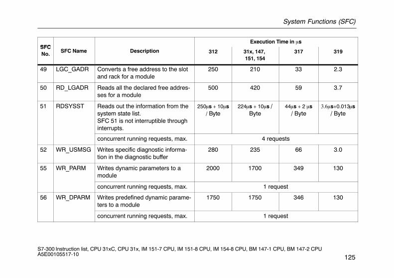
System Functions (SFC)
125S7-300 Instruction list, CPU 31xC, CPU 31x, IM 151-7 CPU, IM 151-8 CPU, IM 154-8 CPU, BM 147-1 CPU, BM 147-2 CPU A5E00105517-10
SFCExecution Time in �s
SFCNo. SFC Name Description 312 31x, 147,
151, 154317 319
49 LGC_GADR Converts a free address to the slotand rack for a module
250 210 33 2.3
50 RD_LGADR Reads all the declared free addres-ses for a module
500 420 59 3.7
51 RDSYSST Reads out the information from thesystem state list.SFC 51 is not interruptible throughinterrupts.
250�s + 10�s/ Byte
224�s + 10�s /Byte
44�s + 2 �s/ Byte
����s+0.013�s/ Byte
concurrent running requests, max. 4 requests
52 WR_USMSG Writes specific diagnostic informa-tion in the diagnostic buffer
280 235 66 3.0
55 WR_PARM Writes dynamic parameters to amodule
2000 1700 349 130
concurrent running requests, max. 1 request
56 WR_DPARM Writes predefined dynamic parame-ters to a module
1750 1750 346 130
concurrent running requests, max. 1 request
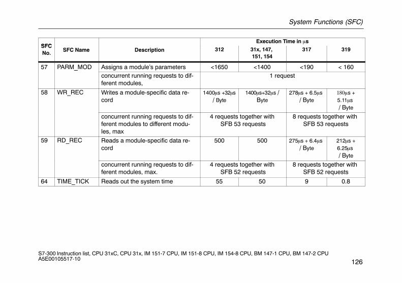
System Functions (SFC)
126S7-300 Instruction list, CPU 31xC, CPU 31x, IM 151-7 CPU, IM 151-8 CPU, IM 154-8 CPU, BM 147-1 CPU, BM 147-2 CPU A5E00105517-10
SFCExecution Time in �s
SFCNo. SFC Name Description 312 31x, 147,
151, 154317 319
57 PARM_MOD Assigns a module’s parameters <1650 <1400 <190 < 160_concurrent running requests to dif-ferent modules,
1 request
58 WR_REC Writes a module-specific data re-cord
1400�s +32�s/ Byte
1400�s+32�s /Byte
278�s + 6.5�s / Byte
����s +5.11�s / Byte
concurrent running requests to dif-ferent modules to different modu-les, max
4 requests together with SFB 53 requests
8 requests together with SFB 53 requests
59 RD_REC Reads a module-specific data re-cord
500 500 275�s + 6.4�s / Byte
212�s +6.25�s / Byte
concurrent running requests to dif-ferent modules, max.
4 requests together with SFB 52 requests
8 requests together with SFB 52 requests
64 TIME_TICK Reads out the system time 55 50 9 0.8
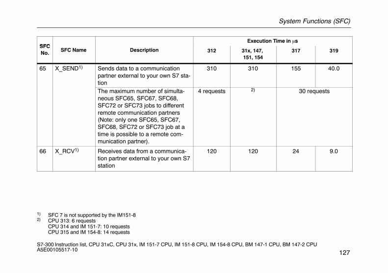
System Functions (SFC)
127S7-300 Instruction list, CPU 31xC, CPU 31x, IM 151-7 CPU, IM 151-8 CPU, IM 154-8 CPU, BM 147-1 CPU, BM 147-2 CPU A5E00105517-10
SFCExecution Time in �s
SFCNo. SFC Name Description 312 31x, 147,
151, 154317 319
65 X_SEND1) Sends data to a communicationpartner external to your own S7 sta-tion
310 310 155 40.0
The maximum number of simulta-neous SFC65, SFC67, SFC68,SFC72 or SFC73 jobs to differentremote communication partners(Note: only one SFC65, SFC67,SFC68, SFC72 or SFC73 job at atime is possible to a remote com-munication partner).
4 requests 2) 30 requests
66 X_RCV1) Receives data from a communica-tion partner external to your own S7station
120 120 24 9.0
1) SFC 7 is not supported by the IM151-82) CPU 313: 6 requests
CPU 314 and IM 151-7: 10 requestsCPU 315 and IM 154-8: 14 requests
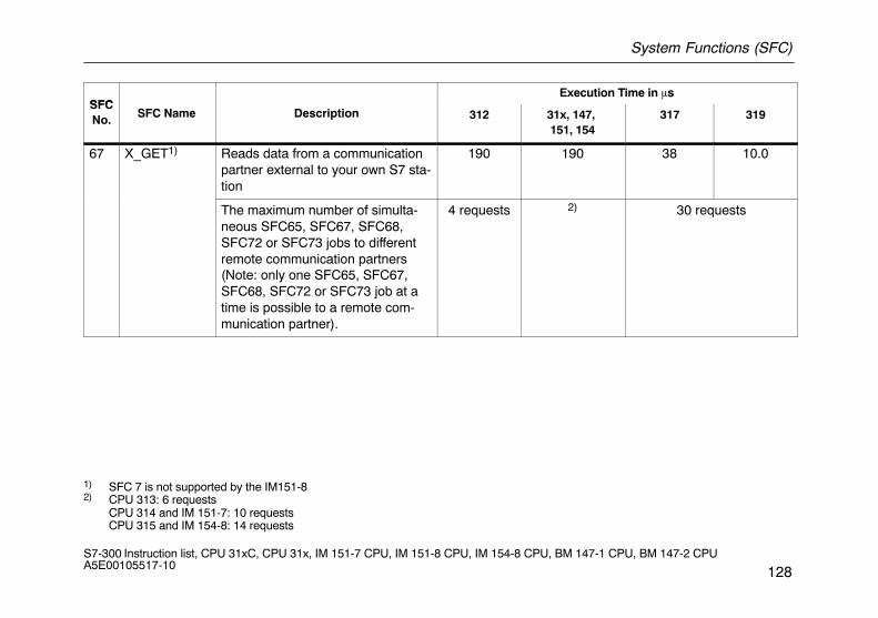
System Functions (SFC)
128S7-300 Instruction list, CPU 31xC, CPU 31x, IM 151-7 CPU, IM 151-8 CPU, IM 154-8 CPU, BM 147-1 CPU, BM 147-2 CPU A5E00105517-10
SFCExecution Time in �s
SFCNo. SFC Name Description 312 31x, 147,
151, 154317 319
67 X_GET1) Reads data from a communicationpartner external to your own S7 sta-tion
190 190 38 10.0
The maximum number of simulta-neous SFC65, SFC67, SFC68,SFC72 or SFC73 jobs to differentremote communication partners(Note: only one SFC65, SFC67,SFC68, SFC72 or SFC73 job at atime is possible to a remote com-munication partner).
4 requests 2) 30 requests
1) SFC 7 is not supported by the IM151-82) CPU 313: 6 requests
CPU 314 and IM 151-7: 10 requestsCPU 315 and IM 154-8: 14 requests
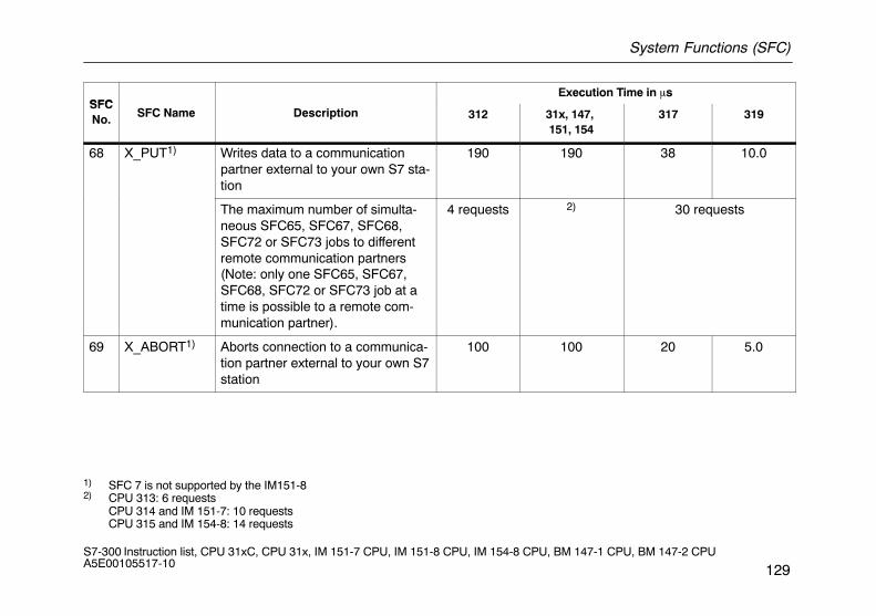
System Functions (SFC)
129S7-300 Instruction list, CPU 31xC, CPU 31x, IM 151-7 CPU, IM 151-8 CPU, IM 154-8 CPU, BM 147-1 CPU, BM 147-2 CPU A5E00105517-10
SFCExecution Time in �s
SFCNo. SFC Name Description 312 31x, 147,
151, 154317 319
68 X_PUT1) Writes data to a communicationpartner external to your own S7 sta-tion
190 190 38 10.0
The maximum number of simulta-neous SFC65, SFC67, SFC68,SFC72 or SFC73 jobs to differentremote communication partners(Note: only one SFC65, SFC67,SFC68, SFC72 or SFC73 job at atime is possible to a remote com-munication partner).
4 requests 2) 30 requests
69 X_ABORT1) Aborts connection to a communica-tion partner external to your own S7station
100 100 20 5.0
1) SFC 7 is not supported by the IM151-82) CPU 313: 6 requests
CPU 314 and IM 151-7: 10 requestsCPU 315 and IM 154-8: 14 requests
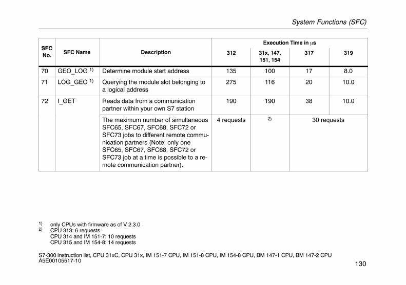
System Functions (SFC)
130S7-300 Instruction list, CPU 31xC, CPU 31x, IM 151-7 CPU, IM 151-8 CPU, IM 154-8 CPU, BM 147-1 CPU, BM 147-2 CPU A5E00105517-10
SFCExecution Time in �s
SFCNo. SFC Name Description 312 31x, 147,
151, 154317 319
70 GEO_LOG 1) Determine module start address 135 100 17 8.0
71 LOG_GEO 1) Querying the module slot belonging toa logical address
275 116 20 10.0
72 I_GET Reads data from a communicationpartner within your own S7 station
190 190 38 10.0
The maximum number of simultaneousSFC65, SFC67, SFC68, SFC72 orSFC73 jobs to different remote commu-nication partners (Note: only oneSFC65, SFC67, SFC68, SFC72 orSFC73 job at a time is possible to a re-mote communication partner).
4 requests 2) 30 requests
1) only CPUs with firmware as of V 2.3.02) CPU 313: 6 requests
CPU 314 and IM 151-7: 10 requestsCPU 315 and IM 154-8: 14 requests
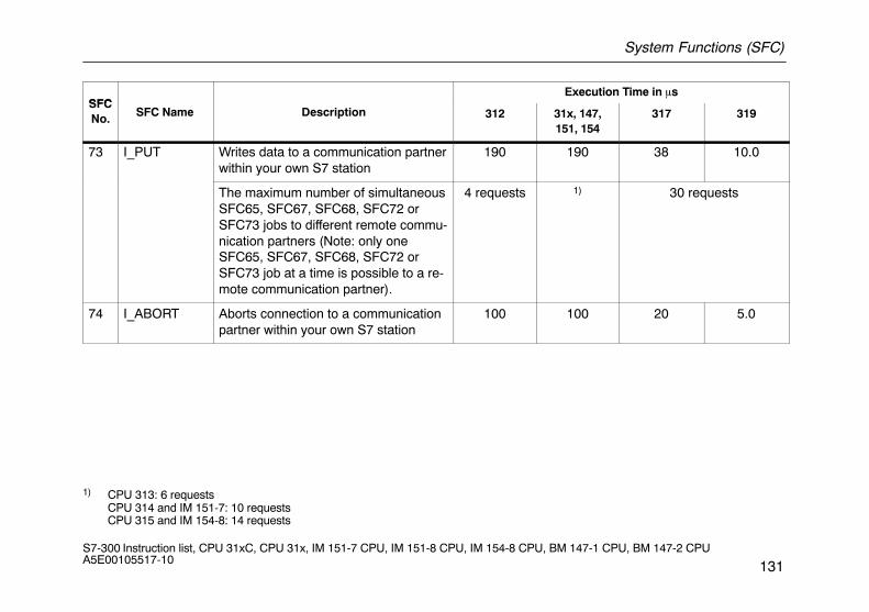
System Functions (SFC)
131S7-300 Instruction list, CPU 31xC, CPU 31x, IM 151-7 CPU, IM 151-8 CPU, IM 154-8 CPU, BM 147-1 CPU, BM 147-2 CPU A5E00105517-10
SFCExecution Time in �s
SFCNo. SFC Name Description 312 31x, 147,
151, 154317 319
73 I_PUT Writes data to a communication partnerwithin your own S7 station
190 190 38 10.0
The maximum number of simultaneousSFC65, SFC67, SFC68, SFC72 orSFC73 jobs to different remote commu-nication partners (Note: only oneSFC65, SFC67, SFC68, SFC72 orSFC73 job at a time is possible to a re-mote communication partner).
4 requests 1) 30 requests
74 I_ABORT Aborts connection to a communicationpartner within your own S7 station
100 100 20 5.0
1) CPU 313: 6 requestsCPU 314 and IM 151-7: 10 requestsCPU 315 and IM 154-8: 14 requests
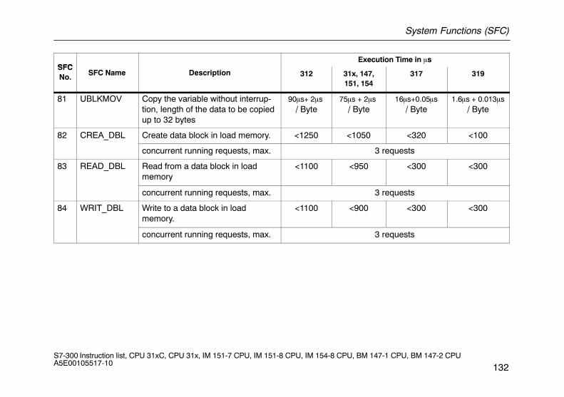
System Functions (SFC)
132S7-300 Instruction list, CPU 31xC, CPU 31x, IM 151-7 CPU, IM 151-8 CPU, IM 154-8 CPU, BM 147-1 CPU, BM 147-2 CPU A5E00105517-10
SFCExecution Time in �s
SFCNo. SFC Name Description 312 31x, 147,
151, 154317 319
81 UBLKMOV Copy the variable without interrup-tion, length of the data to be copiedup to 32 bytes
90�s+ 2�s / Byte
75�s + 2�s / Byte
16�s+0.05�s/ Byte
1.6�s + 0.013�s/ Byte
82 CREA_DBL Create data block in load memory. <1250 <1050 <320 <100
concurrent running requests, max. 3 requests
83 READ_DBL Read from a data block in load memory
<1100 <950 <300 <300
concurrent running requests, max. 3 requests
84 WRIT_DBL Write to a data block in load memory.
<1100 <900 <300 <300
concurrent running requests, max. 3 requests
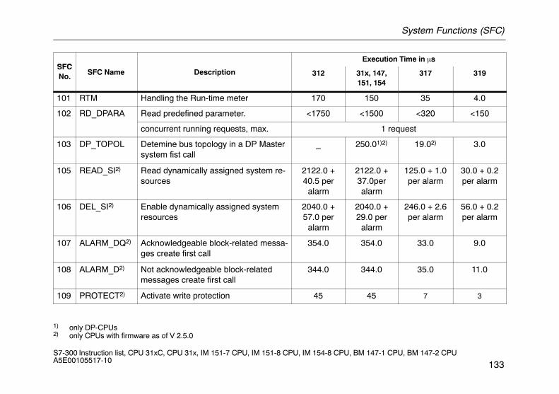
System Functions (SFC)
133S7-300 Instruction list, CPU 31xC, CPU 31x, IM 151-7 CPU, IM 151-8 CPU, IM 154-8 CPU, BM 147-1 CPU, BM 147-2 CPU A5E00105517-10
SFCExecution Time in �s
SFCNo. SFC Name Description 312 31x, 147,
151, 154317 319
101 RTM Handling the Run-time meter 170 150 35 4.0
102 RD_DPARA Read predefined parameter. <1750 <1500 <320 <150
concurrent running requests, max. 1 request
103 DP_TOPOL Detemine bus topology in a DP Mastersystem fist call
_ 250.01)2) 19.02) 3.0
105 READ_SI2) Read dynamically assigned system re-sources
2122.0 +40.5 per
alarm
2122.0 +37.0peralarm
125.0 + 1.0per alarm
30.0 + 0.2per alarm
106 DEL_SI2) Enable dynamically assigned systemresources
2040.0 +57.0 per
alarm
2040.0 +29.0 per
alarm
246.0 + 2.6per alarm
56.0 + 0.2per alarm
107 ALARM_DQ2) Acknowledgeable block-related messa-ges create first call
354.0 354.0 33.0 9.0
108 ALARM_D2) Not acknowledgeable block-relatedmessages create first call
344.0 344.0 35.0 11.0
109 PROTECT2) Activate write protection 45 45 7 3
1) only DP-CPUs2) only CPUs with firmware as of V 2.5.0
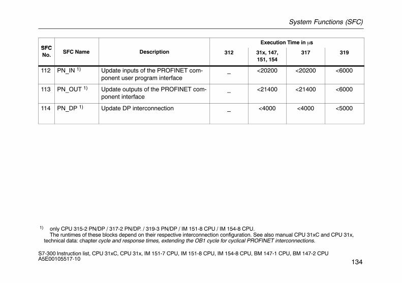
System Functions (SFC)
134S7-300 Instruction list, CPU 31xC, CPU 31x, IM 151-7 CPU, IM 151-8 CPU, IM 154-8 CPU, BM 147-1 CPU, BM 147-2 CPU A5E00105517-10
SFCExecution Time in �s
SFCNo. SFC Name Description 312 31x, 147,
151, 154317 319
112 PN_IN 1) Update inputs of the PROFINET com-ponent user program interface
_ <20200 <20200 <6000
113 PN_OUT 1) Update outputs of the PROFINET com-ponent interface
_ <21400 <21400 <6000
114 PN_DP 1) Update DP interconnection _ <4000 <4000 <5000
1) only CPU 315-2 PN/DP / 317-2 PN/DP. / 319-3 PN/DP / IM 151-8 CPU / IM 154-8 CPU. The runtimes of these blocks depend on their respective interconnection configuration. See also manual CPU 31xC and CPU 31x,
technical data: chapter cycle and response times, extending the OB1 cycle for cyclical PROFINET interconnections.
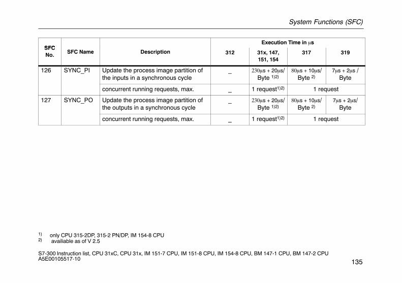
System Functions (SFC)
135S7-300 Instruction list, CPU 31xC, CPU 31x, IM 151-7 CPU, IM 151-8 CPU, IM 154-8 CPU, BM 147-1 CPU, BM 147-2 CPU A5E00105517-10
SFCExecution Time in �s
SFCNo. SFC Name Description 312 31x, 147,
151, 154317 319
126 SYNC_PI Update the process image partition ofthe inputs in a synchronous cycle
_ ���s + 20�s/Byte 1)2)
���s + 10�s/Byte 2)
7�s + 2�s /Byte
concurrent running requests, max. _ 1 request1)2) 1 request
127 SYNC_PO Update the process image partition ofthe outputs in a synchronous cycle
_ ���s + 20�s/Byte 1)2)
���s + 10�s/Byte 2)
7�s + 2�s/Byte
concurrent running requests, max. _ 1 request1)2) 1 request
1) only CPU 315-2DP, 315-2 PN/DP, IM 154-8 CPU2) availiable as of V 2.5
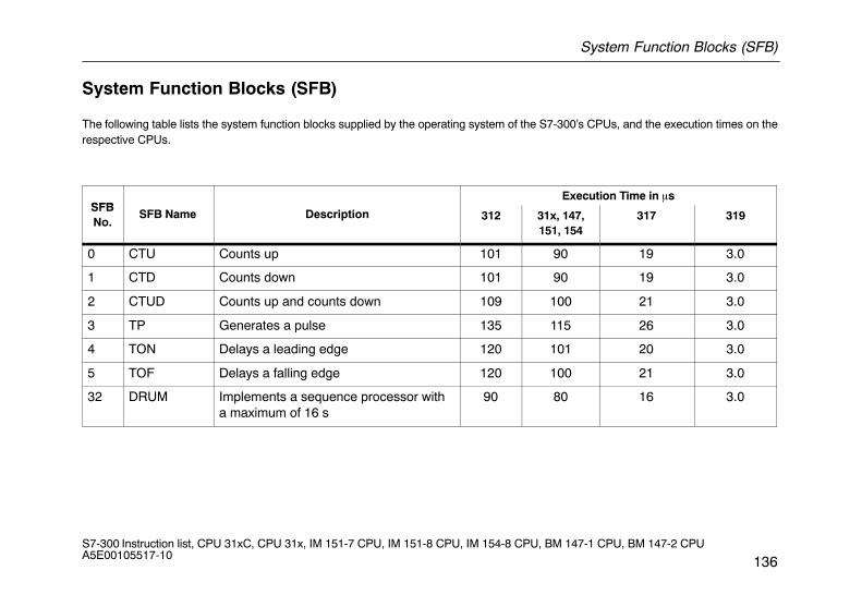
System Function Blocks (SFB)
136S7-300 Instruction list, CPU 31xC, CPU 31x, IM 151-7 CPU, IM 151-8 CPU, IM 154-8 CPU, BM 147-1 CPU, BM 147-2 CPU A5E00105517-10
System Function Blocks (SFB)
The following table lists the system function blocks supplied by the operating system of the S7-300’s CPUs, and the execution times on therespective CPUs.
SFBExecution Time in �s
SFBNo.
SFB Name Description 312 31x, 147,151, 154
317 319
0 CTU Counts up 101 90 19 3.0
1 CTD Counts down 101 90 19 3.0
2 CTUD Counts up and counts down 109 100 21 3.0
3 TP Generates a pulse 135 115 26 3.0
4 TON Delays a leading edge 120 101 20 3.0
5 TOF Delays a falling edge 120 100 21 3.0
32 DRUM Implements a sequence processor witha maximum of 16 s
90 80 16 3.0
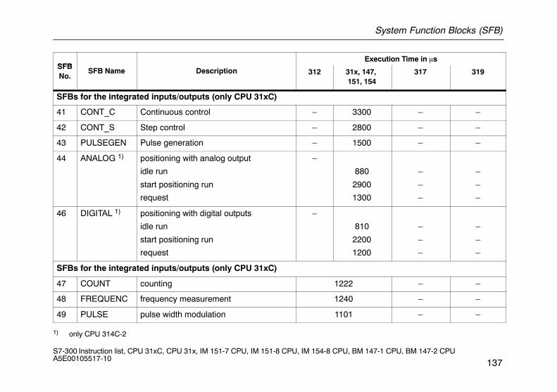
System Function Blocks (SFB)
137S7-300 Instruction list, CPU 31xC, CPU 31x, IM 151-7 CPU, IM 151-8 CPU, IM 154-8 CPU, BM 147-1 CPU, BM 147-2 CPU A5E00105517-10
SFBExecution Time in �s
SFBNo.
SFB Name Description 312 31x, 147, 151, 154
317 319
SFBs for the integrated inputs/outputs (only CPU 31xC)
41 CONT_C Continuous control – 3300 – –
42 CONT_S Step control – 2800 – –
43 PULSEGEN Pulse generation – 1500 – –
44 ANALOG 1) positioning with analog output
idle run
start positioning run
request
–
880
2900
1300
–
–
–
–
–
–
46 DIGITAL 1) positioning with digital outputs
idle run
start positioning run
request
–
810
2200
1200
–
–
–
–
–
–
SFBs for the integrated inputs/outputs (only CPU 31xC)
47 COUNT counting 1222 – –
48 FREQUENC frequency measurement 1240 – –
49 PULSE pulse width modulation 1101 – –
1) only CPU 314C-2
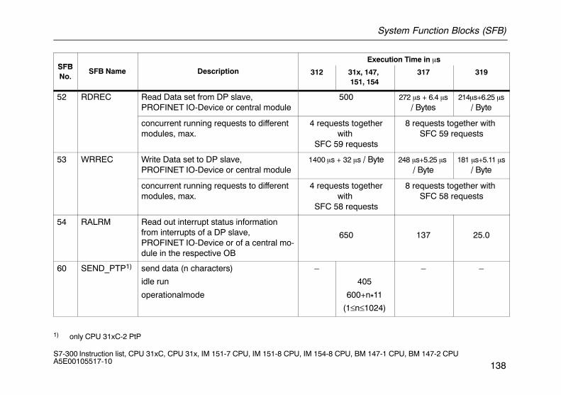
System Function Blocks (SFB)
138S7-300 Instruction list, CPU 31xC, CPU 31x, IM 151-7 CPU, IM 151-8 CPU, IM 154-8 CPU, BM 147-1 CPU, BM 147-2 CPU A5E00105517-10
SFBExecution Time in �s
SFBNo.
SFB Name Description 312 31x, 147, 151, 154
317 319
52 RDREC Read Data set from DP slave, PROFINET IO-Device or central module
500 272 �s + 6.4 �s/ Bytes
214�s+6.25 �s/ Byte
concurrent running requests to differentmodules, max.
4 requests togetherwith
SFC 59 requests
8 requests together with SFC 59 requests
53 WRREC Write Data set to DP slave, PROFINET IO-Device or central module
1400 �s + 32 �s / Byte 248 �s+5.25 �s / Byte
181 �s+5.11 �s/ Byte
concurrent running requests to differentmodules, max.
4 requests togetherwith
SFC 58 requests
8 requests together with SFC 58 requests
54 RALRM Read out interrupt status informationfrom interrupts of a DP slave, PROFINET IO-Device or of a central mo-dule in the respective OB
650 137 25.0
60 SEND_PTP1) send data (n characters)
idle run
operationalmode
–
405
600+n*11
(1≤n≤1024)
– –
1) only CPU 31xC-2 PtP
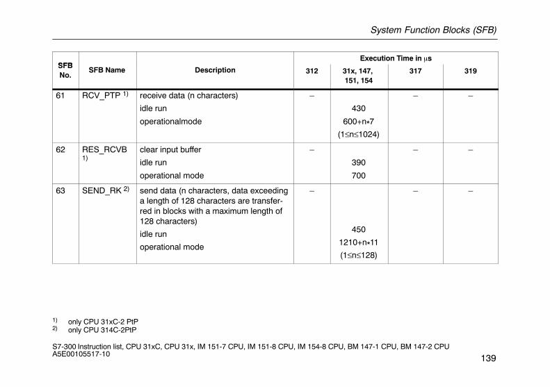
System Function Blocks (SFB)
139S7-300 Instruction list, CPU 31xC, CPU 31x, IM 151-7 CPU, IM 151-8 CPU, IM 154-8 CPU, BM 147-1 CPU, BM 147-2 CPU A5E00105517-10
SFBExecution Time in �s
SFBNo.
SFB Name Description 312 31x, 147, 151, 154
317 319
61 RCV_PTP 1) receive data (n characters)
idle run
operationalmode
–
430
600+n*7
(1≤n≤1024)
– –
62 RES_RCVB1)
clear input buffer
idle run
operational mode
–
390
700
– –
63 SEND_RK 2) send data (n characters, data exceedinga length of 128 characters are transfer-red in blocks with a maximum length of128 characters)
idle run
operational mode
–
450
1210+n*11
(1≤n≤128)
– –
1) only CPU 31xC-2 PtP2) only CPU 314C-2PtP
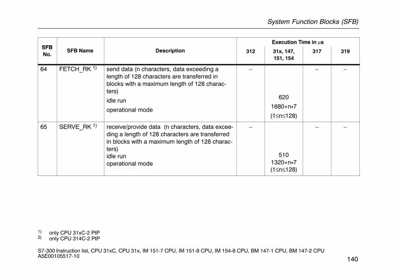
System Function Blocks (SFB)
140S7-300 Instruction list, CPU 31xC, CPU 31x, IM 151-7 CPU, IM 151-8 CPU, IM 154-8 CPU, BM 147-1 CPU, BM 147-2 CPU A5E00105517-10
SFBExecution Time in �s
SFBNo.
SFB Name Description 312 31x, 147,151, 154
317 319
64 FETCH_RK 1) send data (n characters, data exceeding alength of 128 characters are transferred inblocks with a maximum length of 128 charac-ters)
idle run
operational mode
–
620
1680+n*7
(1≤n≤128)
– –
65 SERVE_RK 1) receive/provide data (n characters, data excee-ding a length of 128 characters are transferredin blocks with a maximum length of 128 charac-ters) idle runoperational mode
–
5101320+n*7(1≤n≤128)
– –
1) only CPU 31xC-2 PtP2) only CPU 314C-2 PtP
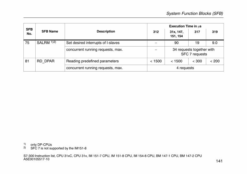
System Function Blocks (SFB)
141S7-300 Instruction list, CPU 31xC, CPU 31x, IM 151-7 CPU, IM 151-8 CPU, IM 154-8 CPU, BM 147-1 CPU, BM 147-2 CPU A5E00105517-10
SFBExecution Time in �s
SFBNo.
SFB Name Description 312 31x, 147,151, 154
317 319
75 SALRM 1)2) Set desired interrupts of I-slaves – 90 19 9.0
concurrent running requests, max. – 34 requests together with SFC 7 requests
81 RD_DPAR Reading predefined parameters < 1500 < 1500 < 300 < 200
concurrent running requests, max. 4 requests
1) only DP-CPUs2) SFC 7 is not supported by the IM151-8
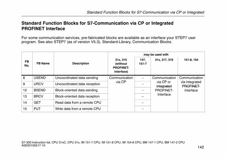
Standard Function Blocks for S7-Communication via CP or Integrated
142S7-300 Instruction list, CPU 31xC, CPU 31x, IM 151-7 CPU, IM 151-8 CPU, IM 154-8 CPU, BM 147-1 CPU, BM 147-2 CPU A5E00105517-10
Standard Function Blocks for S7-Communication via CP or Integrated PROFINET Interface
For some communication services, pre-fabricated blocks are available as an interface your STEP7 user program. See also STEP7 (as of version V5.3), Standard-Library, Communication Blocks.
may be used with
FBNo.
FB Name Description31x, 315(without
PROFINET-Interface)
147,151-7
31x, 317, 319 151-8, 154
8 USEND Uncoordinated data sending Communicationi CP
– Communicationi CP
Communicationi i t t d
9 URCV Uncoordinated data receptionvia CP
–via CP or integrated
via integratedPROFINET-
12 BSEND Block-oriented data sending –integrated
PROFINET-I t f
PROFINET-Interface
13 BRCV Block-oriented data reception – Interface
14 GET Read data from a remote CPU –
15 PUT Write data from a remote CPU –
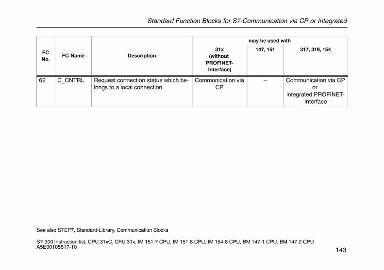
Standard Function Blocks for S7-Communication via CP or Integrated
143S7-300 Instruction list, CPU 31xC, CPU 31x, IM 151-7 CPU, IM 151-8 CPU, IM 154-8 CPU, BM 147-1 CPU, BM 147-2 CPU A5E00105517-10
may be used with
FCNo.
FC-Name Description31x
(without PROFINET-Interface)
147, 151 317, 319, 154
62 C_CNTRL Request connection status which be-longs to a local connection.
Communication viaCP
– Communication via CPor
integrated PROFINET-Interface
See also STEP7, Standard-Library, Communication Blocks
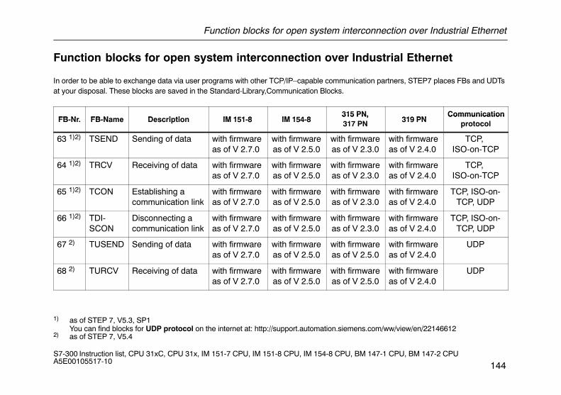
Function blocks for open system interconnection over Industrial Ethernet
144S7-300 Instruction list, CPU 31xC, CPU 31x, IM 151-7 CPU, IM 151-8 CPU, IM 154-8 CPU, BM 147-1 CPU, BM 147-2 CPU A5E00105517-10
Function blocks for open system interconnection over Industrial Ethernet
In order to be able to exchange data via user programs with other TCP/IP–capable communication partners, STEP7 places FBs and UDTsat your disposal. These blocks are saved in the Standard-Library,Communication Blocks.
FB Nr FB Name Description IM 151 8 IM 154 8315 PN,
319 PNCommunication
FB-Nr. FB-Name Description IM 151-8 IM 154-8315 PN,317 PN 319 PN
Communicationprotocol
63 1)2) TSEND Sending of data with firmwareas of V 2.7.0
with firmwareas of V 2.5.0
with firmwareas of V 2.3.0
with firmwareas of V 2.4.0
TCP, ISO-on-TCP
64 1)2) TRCV Receiving of data with firmwareas of V 2.7.0
with firmwareas of V 2.5.0
with firmwareas of V 2.3.0
with firmwareas of V 2.4.0
TCP, ISO-on-TCP
65 1)2) TCON Establishing a communication link
with firmwareas of V 2.7.0
with firmwareas of V 2.5.0
with firmwareas of V 2.3.0
with firmwareas of V 2.4.0
TCP, ISO-on-TCP, UDP
66 1)2) TDI-SCON
Disconnecting a communication link
with firmwareas of V 2.7.0
with firmwareas of V 2.5.0
with firmwareas of V 2.3.0
with firmwareas of V 2.4.0
TCP, ISO-on-TCP, UDP
67 2) TUSEND Sending of data with firmwareas of V 2.7.0
with firmwareas of V 2.5.0
with firmwareas of V 2.5.0
with firmwareas of V 2.4.0
UDP
68 2) TURCV Receiving of data with firmwareas of V 2.7.0
with firmwareas of V 2.5.0
with firmwareas of V 2.5.0
with firmwareas of V 2.4.0
UDP
1) as of STEP 7, V5.3, SP1You can find blocks for UDP protocol on the internet at: http://support.automation.siemens.com/ww/view/en/22146612
2) as of STEP 7, V5.4
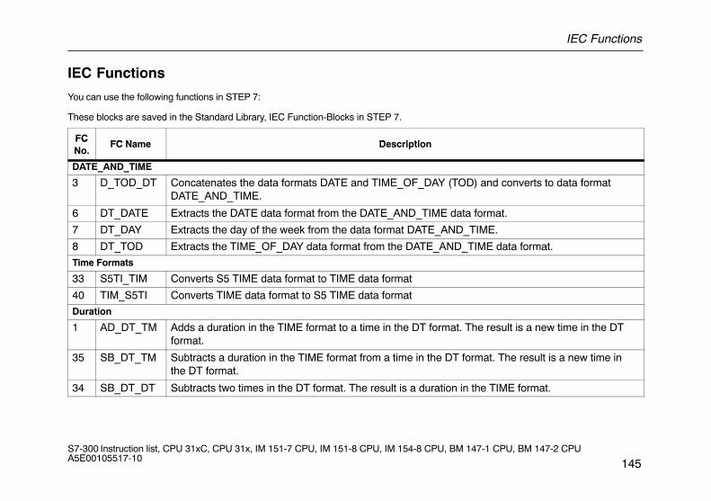
IEC Functions
145S7-300 Instruction list, CPU 31xC, CPU 31x, IM 151-7 CPU, IM 151-8 CPU, IM 154-8 CPU, BM 147-1 CPU, BM 147-2 CPU A5E00105517-10
IEC Functions
You can use the following functions in STEP 7:
These blocks are saved in the Standard Library, IEC Function-Blocks in STEP 7.
FCFC Name Description
FCNo.
FC Name Description
DATE_AND_TIME
3 D_TOD_DT Concatenates the data formats DATE and TIME_OF_DAY (TOD) and converts to data formatDATE_AND_TIME.
6 DT_DATE Extracts the DATE data format from the DATE_AND_TIME data format.
7 DT_DAY Extracts the day of the week from the data format DATE_AND_TIME.
8 DT_TOD Extracts the TIME_OF_DAY data format from the DATE_AND_TIME data format.
Time Formats
33 S5TI_TIM Converts S5 TIME data format to TIME data format
40 TIM_S5TI Converts TIME data format to S5 TIME data format
Duration
1 AD_DT_TM Adds a duration in the TIME format to a time in the DT format. The result is a new time in the DTformat.
35 SB_DT_TM Subtracts a duration in the TIME format from a time in the DT format. The result is a new time inthe DT format.
34 SB_DT_DT Subtracts two times in the DT format. The result is a duration in the TIME format.
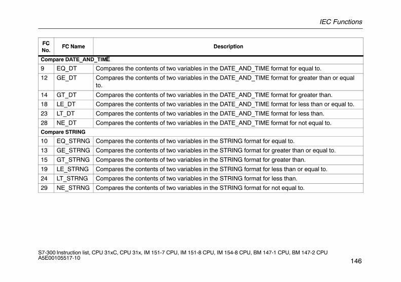
IEC Functions
146S7-300 Instruction list, CPU 31xC, CPU 31x, IM 151-7 CPU, IM 151-8 CPU, IM 154-8 CPU, BM 147-1 CPU, BM 147-2 CPU A5E00105517-10
FCFC Name Description
FCNo.
FC Name Description
Compare DATE_AND_TIME
9 EQ_DT Compares the contents of two variables in the DATE_AND_TIME format for equal to.
12 GE_DT Compares the contents of two variables in the DATE_AND_TIME format for greater than or equalto.
14 GT_DT Compares the contents of two variables in the DATE_AND_TIME format for greater than.
18 LE_DT Compares the contents of two variables in the DATE_AND_TIME format for less than or equal to.
23 LT_DT Compares the contents of two variables in the DATE_AND_TIME format for less than.
28 NE_DT Compares the contents of two variables in the DATE_AND_TIME format for not equal to.
Compare STRING
10 EQ_STRNG Compares the contents of two variables in the STRING format for equal to.
13 GE_STRNG Compares the contents of two variables in the STRING format for greater than or equal to.
15 GT_STRNG Compares the contents of two variables in the STRING format for greater than.
19 LE_STRNG Compares the contents of two variables in the STRING format for less than or equal to.
24 LT_STRNG Compares the contents of two variables in the STRING format for less than.
29 NE_STRNG Compares the contents of two variables in the STRING format for not equal to.
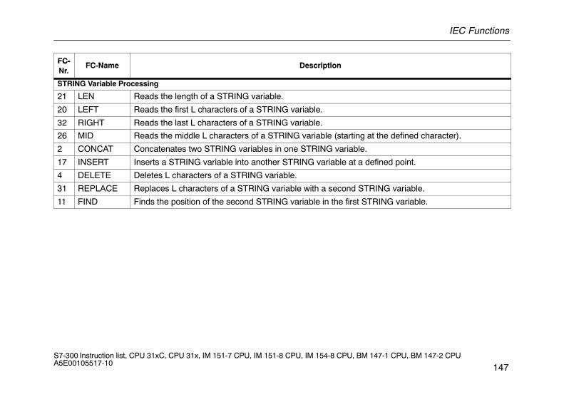
IEC Functions
147S7-300 Instruction list, CPU 31xC, CPU 31x, IM 151-7 CPU, IM 151-8 CPU, IM 154-8 CPU, BM 147-1 CPU, BM 147-2 CPU A5E00105517-10
FC-FC Name Description
FC-Nr.
FC-Name Description
STRING Variable Processing
21 LEN Reads the length of a STRING variable.
20 LEFT Reads the first L characters of a STRING variable.
32 RIGHT Reads the last L characters of a STRING variable.
26 MID Reads the middle L characters of a STRING variable (starting at the defined character).
2 CONCAT Concatenates two STRING variables in one STRING variable.
17 INSERT Inserts a STRING variable into another STRING variable at a defined point.
4 DELETE Deletes L characters of a STRING variable.
31 REPLACE Replaces L characters of a STRING variable with a second STRING variable.
11 FIND Finds the position of the second STRING variable in the first STRING variable.
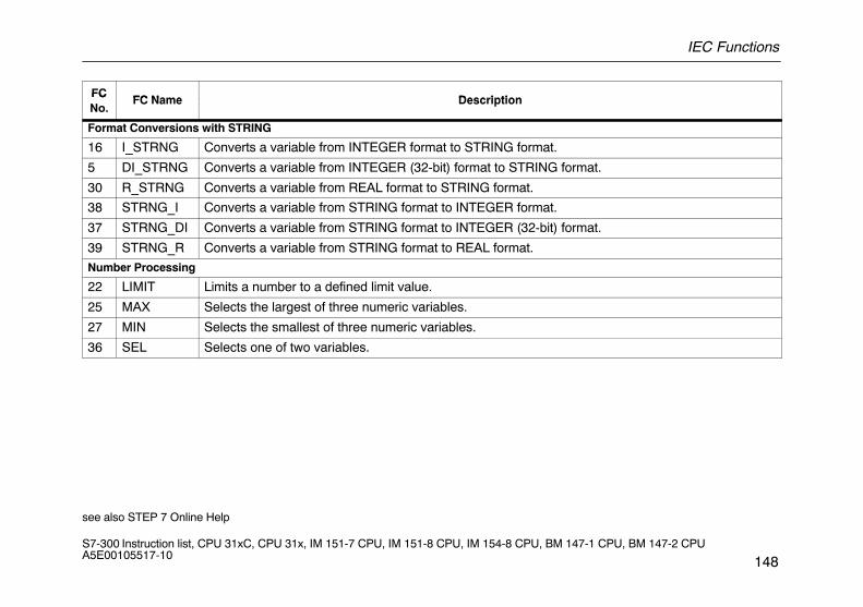
IEC Functions
148S7-300 Instruction list, CPU 31xC, CPU 31x, IM 151-7 CPU, IM 151-8 CPU, IM 154-8 CPU, BM 147-1 CPU, BM 147-2 CPU A5E00105517-10
FCFC Name Description
FCNo.
FC Name Description
Format Conversions with STRING
16 I_STRNG Converts a variable from INTEGER format to STRING format.
5 DI_STRNG Converts a variable from INTEGER (32-bit) format to STRING format.
30 R_STRNG Converts a variable from REAL format to STRING format.
38 STRNG_I Converts a variable from STRING format to INTEGER format.
37 STRNG_DI Converts a variable from STRING format to INTEGER (32-bit) format.
39 STRNG_R Converts a variable from STRING format to REAL format.
Number Processing
22 LIMIT Limits a number to a defined limit value.
25 MAX Selects the largest of three numeric variables.
27 MIN Selects the smallest of three numeric variables.
36 SEL Selects one of two variables.
see also STEP 7 Online Help
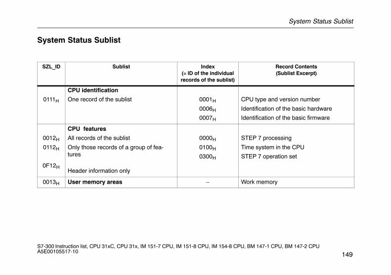
System Status Sublist
149S7-300 Instruction list, CPU 31xC, CPU 31x, IM 151-7 CPU, IM 151-8 CPU, IM 154-8 CPU, BM 147-1 CPU, BM 147-2 CPU A5E00105517-10
System Status Sublist
SZL_ID Sublist Index(= ID of the individualrecords of the sublist)
Record Contents(Sublist Excerpt)
0111H
CPU identification
One record of the sublist 0001H
0006H
0007H
CPU type and version number
Identification of the basic hardware
Identification of the basic firmware
0012H
0112H
0F12H
CPU features
All records of the sublist
Only those records of a group of fea-tures
Header information only
0000H
0100H
0300H
STEP 7 processing
Time system in the CPU
STEP 7 operation set
0013H User memory areas – Work memory
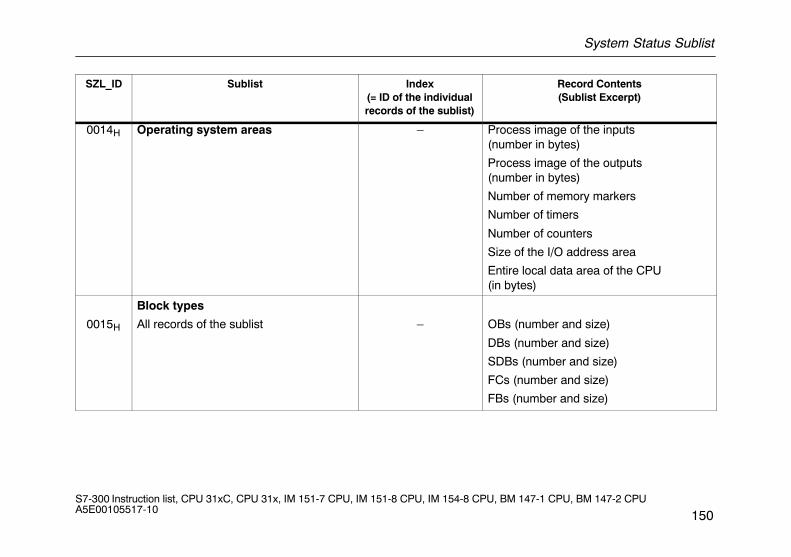
System Status Sublist
150S7-300 Instruction list, CPU 31xC, CPU 31x, IM 151-7 CPU, IM 151-8 CPU, IM 154-8 CPU, BM 147-1 CPU, BM 147-2 CPU A5E00105517-10
SZL_ID Record Contents(Sublist Excerpt)
Index(= ID of the individualrecords of the sublist)
Sublist
0014H Operating system areas – Process image of the inputs(number in bytes)
Process image of the outputs (number in bytes)
Number of memory markers
Number of timers
Number of counters
Size of the I/O address area
Entire local data area of the CPU (in bytes)
0015H
Block types
All records of the sublist – OBs (number and size)
DBs (number and size)
SDBs (number and size)
FCs (number and size)
FBs (number and size)
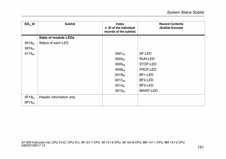
System Status Sublist
151S7-300 Instruction list, CPU 31xC, CPU 31x, IM 151-7 CPU, IM 151-8 CPU, IM 154-8 CPU, BM 147-1 CPU, BM 147-2 CPU A5E00105517-10
SZL_ID Record Contents(Sublist Excerpt)
Index(= ID of the individualrecords of the sublist)
Sublist
0019H
0074H
0174H
State of module LEDs
Status of each LED
0001H
0004H
0005H
0006H
001BH
001CH
0014H
0015H
–
SF-LED
RUN-LED
STOP-LED
FRCE-LED
BF1-LED
BF2-LED
BF3-LED
MAINT-LED
0F19H
0F74H
Header information only
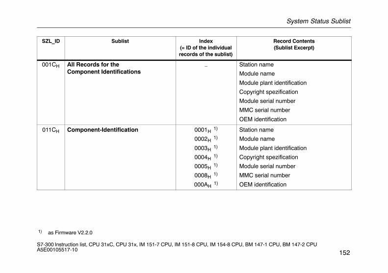
System Status Sublist
152S7-300 Instruction list, CPU 31xC, CPU 31x, IM 151-7 CPU, IM 151-8 CPU, IM 154-8 CPU, BM 147-1 CPU, BM 147-2 CPU A5E00105517-10
SZL_ID Record Contents(Sublist Excerpt)
Index(= ID of the individualrecords of the sublist)
Sublist
001CH All Records for theComponent Identifications
– Station name
Module name
Module plant identification
Copyright spezification
Module serial number
MMC serial number
OEM identification
011CH Component-Identification 0001H 1)
0002H 1)
0003H 1)
0004H 1)
0005H 1)
0008H 1)
000AH 1)
Station name
Module name
Module plant identification
Copyright spezification
Module serial number
MMC serial number
OEM identification
1) as Firmware V2.2.0
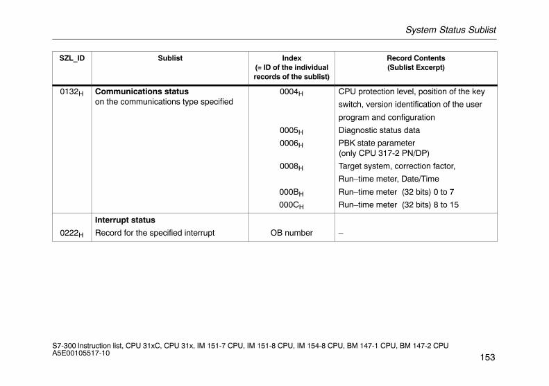
System Status Sublist
153S7-300 Instruction list, CPU 31xC, CPU 31x, IM 151-7 CPU, IM 151-8 CPU, IM 154-8 CPU, BM 147-1 CPU, BM 147-2 CPU A5E00105517-10
SZL_ID Sublist Index(= ID of the individualrecords of the sublist)
Record Contents(Sublist Excerpt)
0132H Communications status on the communications type specified
0004H
0005H
0006H
0008H
000BH
000CH
CPU protection level, position of the key
switch, version identification of the user
program and configuration
Diagnostic status data
PBK state parameter (only CPU 317-2 PN/DP)
Target system, correction factor,
Run–time meter, Date/Time
Run–time meter (32 bits) 0 to 7
Run–time meter (32 bits) 8 to 15
0222H
Interrupt status
Record for the specified interrupt OB number –
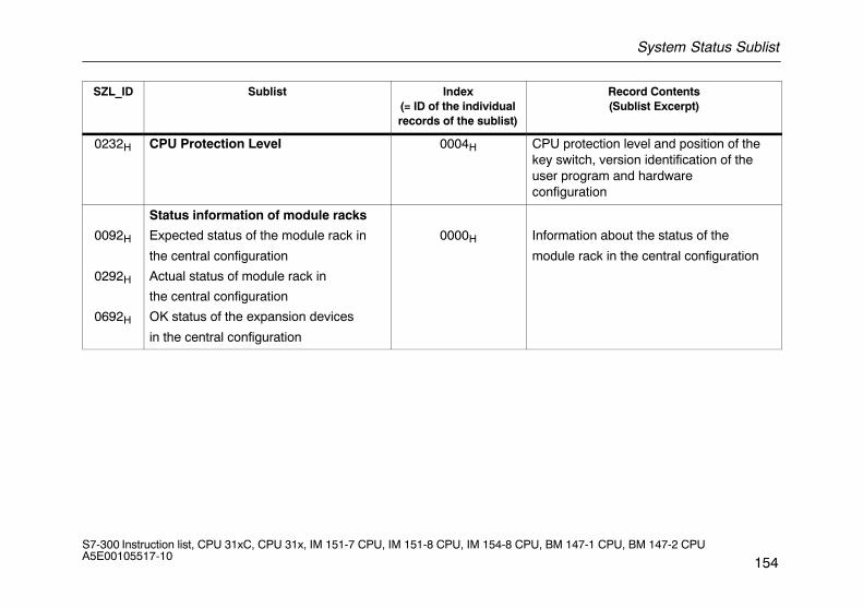
System Status Sublist
154S7-300 Instruction list, CPU 31xC, CPU 31x, IM 151-7 CPU, IM 151-8 CPU, IM 154-8 CPU, BM 147-1 CPU, BM 147-2 CPU A5E00105517-10
SZL_ID Record Contents(Sublist Excerpt)
Index(= ID of the individualrecords of the sublist)
Sublist
0232H CPU Protection Level 0004H CPU protection level and position of thekey switch, version identification of theuser program and hardware configuration
0092H
0292H
0692H
Status information of module racks
Expected status of the module rack in
the central configuration
Actual status of module rack in
the central configuration
OK status of the expansion devices
in the central configuration
0000H Information about the status of the
module rack in the central configuration
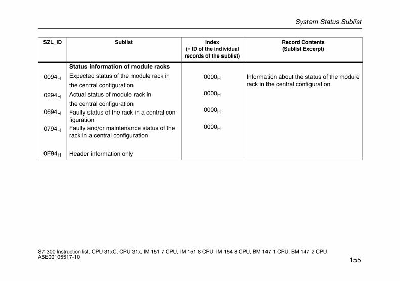
System Status Sublist
155S7-300 Instruction list, CPU 31xC, CPU 31x, IM 151-7 CPU, IM 151-8 CPU, IM 154-8 CPU, BM 147-1 CPU, BM 147-2 CPU A5E00105517-10
SZL_ID Record Contents(Sublist Excerpt)
Index(= ID of the individualrecords of the sublist)
Sublist
0094H
0294H
0694H
0794H
0F94H
Status information of module racks
Expected status of the module rack in
the central configuration
Actual status of module rack in
the central configurationFaulty status of the rack in a central con-figurationFaulty and/or maintenance status of therack in a central configuration
Header information only
0000H
0000H
0000H
0000H
Information about the status of the modulerack in the central configuration

System Status Sublist
156S7-300 Instruction list, CPU 31xC, CPU 31x, IM 151-7 CPU, IM 151-8 CPU, IM 154-8 CPU, BM 147-1 CPU, BM 147-2 CPU A5E00105517-10
SZL_ID Record Contents(Sublist Excerpt)
Index(= ID of the individualrecords of the sublist)
Sublist
0591H
0C91H
0D91H
Module status informationof all submodules of the host moduleModule status informationof a module in the central rack or con-nected to an integrated DP interface mo-duleModule status informationof all modules in the specified rack (all CPUs)
any logic address ofa module
0000H
0001H
0002H0003H
Features/parameters of the moduleplugged in
Features/parameters of the moduleplugged in
Rack 0
Rack 1
Rack 2
Rack 3
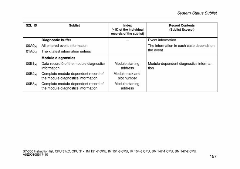
System Status Sublist
157S7-300 Instruction list, CPU 31xC, CPU 31x, IM 151-7 CPU, IM 151-8 CPU, IM 154-8 CPU, BM 147-1 CPU, BM 147-2 CPU A5E00105517-10
SZL_ID Sublist Index(= ID of the individualrecords of the sublist)
Record Contents(Sublist Excerpt)
00A0H
01A0H
Diagnostic buffer
All entered event information
The x latest information entries
– Event information
The information in each case depends onthe event
00B1H
00B2H
00B3H
Module diagnostics
Data record 0 of the module diagnosticsinformation
Complete module-dependent record ofthe module diagnostics information
Complete module-dependent record ofthe module diagnostics information
Module starting address
Module rack and slot number
Module starting address
Module-dependent diagnostics informa-tion
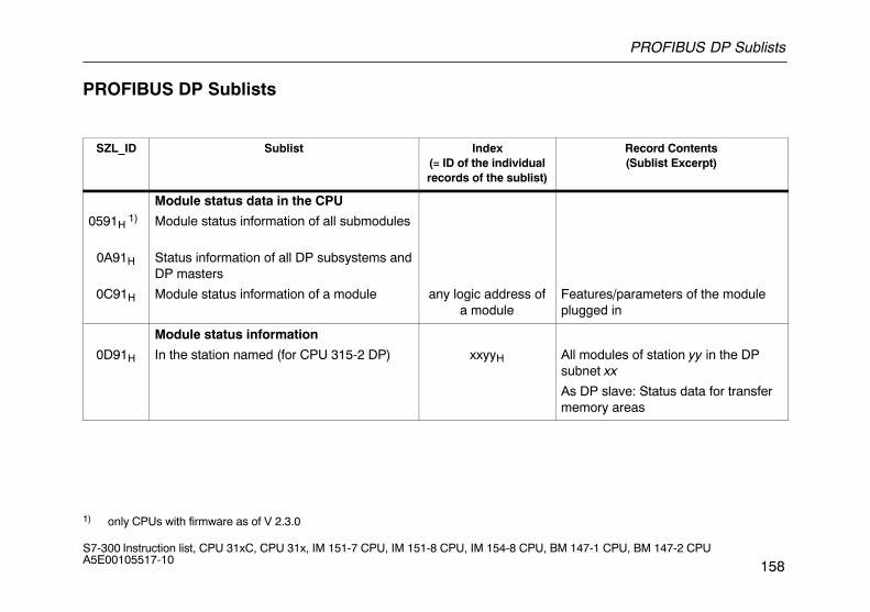
PROFIBUS DP Sublists
158S7-300 Instruction list, CPU 31xC, CPU 31x, IM 151-7 CPU, IM 151-8 CPU, IM 154-8 CPU, BM 147-1 CPU, BM 147-2 CPU A5E00105517-10
PROFIBUS DP Sublists
SZL_ID Sublist Index(= ID of the individualrecords of the sublist)
Record Contents(Sublist Excerpt)
0591H 1)
0A91H
0C91H
Module status data in the CPU
Module status information of all submodules
Status information of all DP subsystems andDP masters
Module status information of a module
any logic address ofa module
Features/parameters of the moduleplugged in
0D91H
Module status information
In the station named (for CPU 315-2 DP) xxyyH All modules of station yy in the DPsubnet xx
As DP slave: Status data for transfermemory areas
1) only CPUs with firmware as of V 2.3.0

PROFIBUS DP Sublists
159S7-300 Instruction list, CPU 31xC, CPU 31x, IM 151-7 CPU, IM 151-8 CPU, IM 154-8 CPU, BM 147-1 CPU, BM 147-2 CPU A5E00105517-10
SZL_ID Record Contents(Sublist Excerpt)
Index(= ID of the individualrecords of the sublist)
Sublist
0092H
0292H
0692H
Status information of module racks orstations in the DP network
Target status of racks in central configura-tion or of stations in a subnet
Actual status of racks in central configura-tion or of stations in a subnet
OK status of expansion racks in central con-figuration or of stations in a subnet
0000H
DP master system ID
Information on the state of the mount-ing rack in the central configuration
Information of status of stations insubnet
0094H 1)
0294H 1)
0694H 1)
0F94H 1)
Station status in a DP subnet
Expected status of the stations in a subnet
Current status of the stations
all faulty or non-existing stations
only header information
DP master system ID
DP master system ID
DP master system ID
Status of the devices in a DP subnet
1) only CPUs with firmware as of V 2.3.0
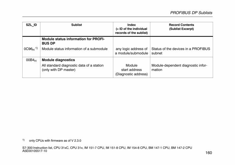
PROFIBUS DP Sublists
160S7-300 Instruction list, CPU 31xC, CPU 31x, IM 151-7 CPU, IM 151-8 CPU, IM 154-8 CPU, BM 147-1 CPU, BM 147-2 CPU A5E00105517-10
SZL_ID Record Contents(Sublist Excerpt)
Index(= ID of the individualrecords of the sublist)
Sublist
0C96H 1)
Module status information for PROFI-BUS DP
Module status information of a submodule
any logic address ofa module/submodule
Status of the devices in a PROFIBUSsubnet
00B4H Module diagnostics
All standard diagnostic data of a station(only with DP master)
Modulestart address
(Diagnostic address)
Module-dependent diagnostic infor-mation
1) only CPUs with firmware as of V 2.3.0
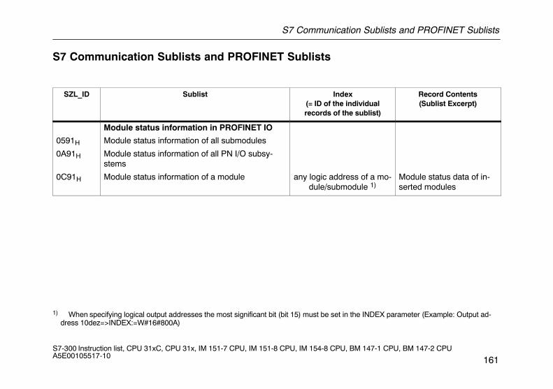
S7 Communication Sublists and PROFINET Sublists
161S7-300 Instruction list, CPU 31xC, CPU 31x, IM 151-7 CPU, IM 151-8 CPU, IM 154-8 CPU, BM 147-1 CPU, BM 147-2 CPU A5E00105517-10
S7 Communication Sublists and PROFINET Sublists
SZL_ID Sublist Index(= ID of the individualrecords of the sublist)
Record Contents(Sublist Excerpt)
0591H
0A91H
0C91H
Module status information in PROFINET IO
Module status information of all submodules
Module status information of all PN I/O subsy-stems
Module status information of a module
any logic address of a mo-dule/submodule 1)
Module status data of in-serted modules
1) When specifying logical output addresses the most significant bit (bit 15) must be set in the INDEX parameter (Example: Output ad-dress 10dez=>INDEX:=W#16#800A)
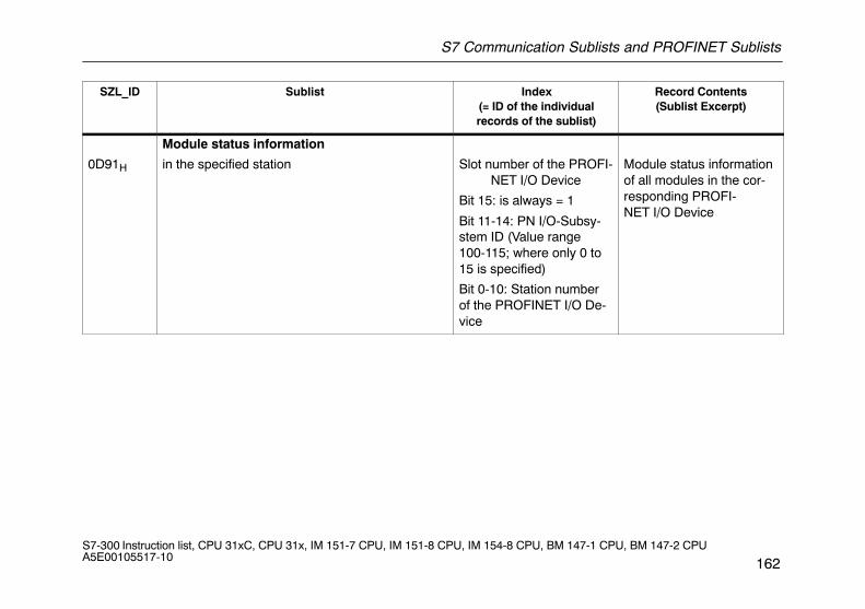
S7 Communication Sublists and PROFINET Sublists
162S7-300 Instruction list, CPU 31xC, CPU 31x, IM 151-7 CPU, IM 151-8 CPU, IM 154-8 CPU, BM 147-1 CPU, BM 147-2 CPU A5E00105517-10
SZL_ID Record Contents(Sublist Excerpt)
Index(= ID of the individualrecords of the sublist)
Sublist
0D91H
Module status information
in the specified station Slot number of the PROFI-NET I/O Device
Bit 15: is always = 1
Bit 11-14: PN I/O-Subsy-stem ID (Value range100-115; where only 0 to15 is specified)
Bit 0-10: Station numberof the PROFINET I/O De-vice
Module status informationof all modules in the cor-responding PROFI-NET I/O Device
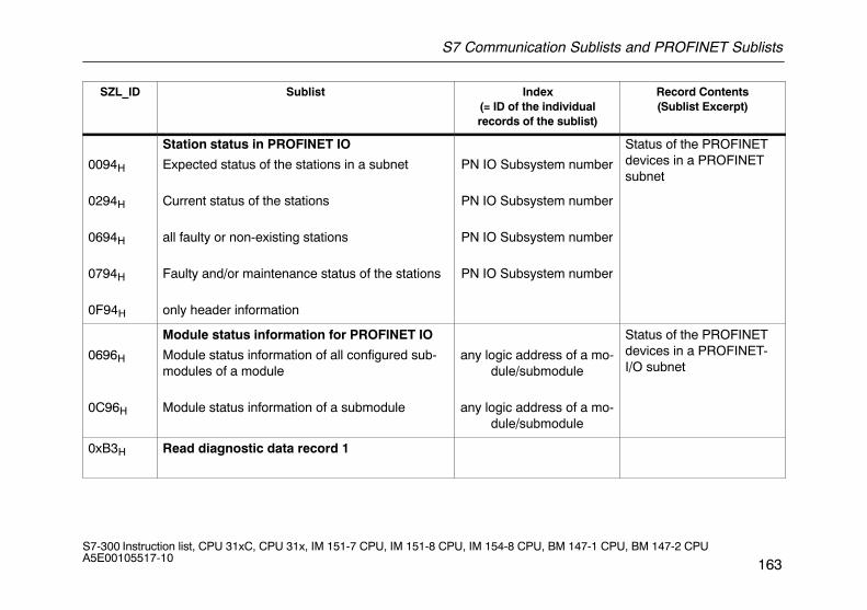
S7 Communication Sublists and PROFINET Sublists
163S7-300 Instruction list, CPU 31xC, CPU 31x, IM 151-7 CPU, IM 151-8 CPU, IM 154-8 CPU, BM 147-1 CPU, BM 147-2 CPU A5E00105517-10
SZL_ID Record Contents(Sublist Excerpt)
Index(= ID of the individualrecords of the sublist)
Sublist
0094H
0294H
0694H
0794H
0F94H
Station status in PROFINET IO
Expected status of the stations in a subnet
Current status of the stations
all faulty or non-existing stations
Faulty and/or maintenance status of the stations
only header information
PN IO Subsystem number
PN IO Subsystem number
PN IO Subsystem number
PN IO Subsystem number
Status of the PROFINETdevices in a PROFINETsubnet
0696H
0C96H
Module status information for PROFINET IO
Module status information of all configured sub-modules of a module
Module status information of a submodule
any logic address of a mo-dule/submodule
any logic address of a mo-dule/submodule
Status of the PROFINETdevices in a PROFINET-I/O subnet
0xB3H
Read diagnostic data record 1
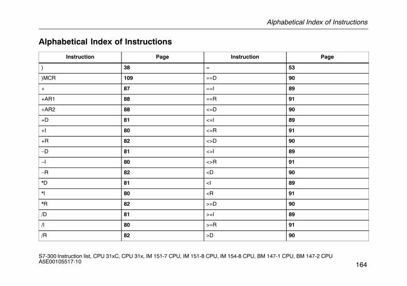
Alphabetical Index of Instructions
164S7-300 Instruction list, CPU 31xC, CPU 31x, IM 151-7 CPU, IM 151-8 CPU, IM 154-8 CPU, BM 147-1 CPU, BM 147-2 CPU A5E00105517-10
Alphabetical Index of Instructions
Instruction Page Instruction Page
) 38 = 53
)MCR 109 ==D 90
+ 87 ==I 89
+AR1 88 ==R 91
+AR2 88 <=D 90
+D 81 <=I 89
+I 80 <=R 91
+R 82 <>D 90
–D 81 <>I 89
–I 80 <>R 91
–R 82 <D 90
*D 81 <I 89
*I 80 <R 91
*R 82 >=D 90
/D 81 >=I 89
/I 80 >=R 91
/R 82 >D 90
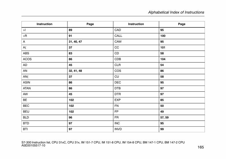
Alphabetical Index of Instructions
165S7-300 Instruction list, CPU 31xC, CPU 31x, IM 151-7 CPU, IM 151-8 CPU, IM 154-8 CPU, BM 147-1 CPU, BM 147-2 CPU A5E00105517-10
Instruction Page Instruction Page
>I 89 CAD 95
>R 91 CALL 100
A 31, 40, 47 CAW 95
A( 37 CC 101
ABS 83 CD 58
ACOS 86 CDB 104
AD 45 CLR 54
AN 32, 41, 48 COS 86
AN( 37 CU 58
ASIN 86 DEC 95
ATAN 86 DTB 97
AW 45 DTR 97
BE 102 EXP 85
BEC 102 FN 50
BEU 102 FP 49
BLD 96 FR 57, 59
BTD 97 INC 95
BTI 97 INVD 99
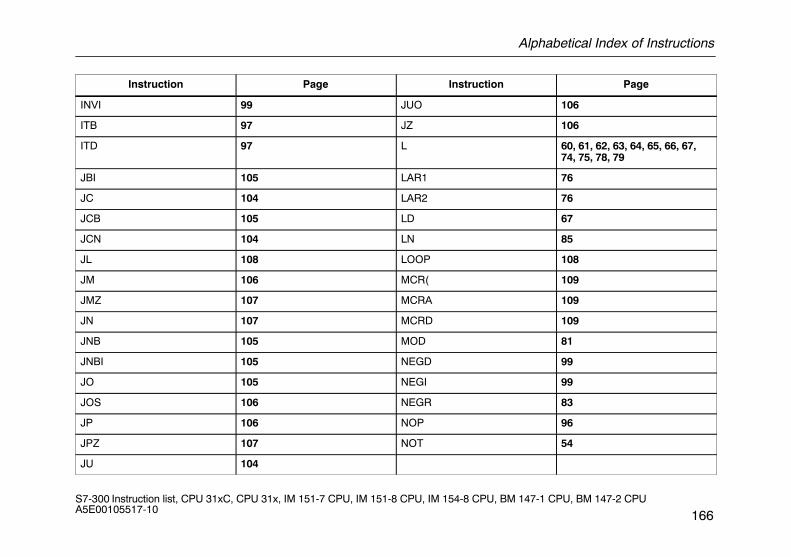
Alphabetical Index of Instructions
166S7-300 Instruction list, CPU 31xC, CPU 31x, IM 151-7 CPU, IM 151-8 CPU, IM 154-8 CPU, BM 147-1 CPU, BM 147-2 CPU A5E00105517-10
Instruction Page Instruction Page
INVI 99 JUO 106
ITB 97 JZ 106
ITD 97 L 60, 61, 62, 63, 64, 65, 66, 67,74, 75, 78, 79
JBI 105 LAR1 76
JC 104 LAR2 76
JCB 105 LD 67
JCN 104 LN 85
JL 108 LOOP 108
JM 106 MCR( 109
JMZ 107 MCRA 109
JN 107 MCRD 109
JNB 105 MOD 81
JNBI 105 NEGD 99
JO 105 NEGI 99
JOS 106 NEGR 83
JP 106 NOP 96
JPZ 107 NOT 54
JU 104
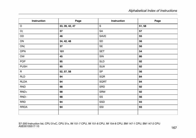
Alphabetical Index of Instructions
167S7-300 Instruction list, CPU 31xC, CPU 31x, IM 151-7 CPU, IM 151-8 CPU, IM 154-8 CPU, BM 147-1 CPU, BM 147-2 CPU A5E00105517-10
Instruction Page Instruction Page
O 33, 39, 42, 47 S 51, 58
O( 37 SA 57
OD 46 SAVE 55
ON 34, 42, 48 SD 56
ON( 37 SE 56
OPN 101 SET 54
OW 45 SIN 86
POP 95 SLD 92
PUSH 95 SLW 92
R 52, 57, 58 SP 56
RLD 94 SQR 84
RLDA 94 SQRT 84
RND 98 SRD 92
RND+ 98 SRW 92
RND– 98 SS 56
RRD 94 SSD 93
RRDA 94 SSI 93
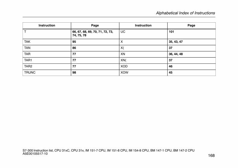
Alphabetical Index of Instructions
168S7-300 Instruction list, CPU 31xC, CPU 31x, IM 151-7 CPU, IM 151-8 CPU, IM 154-8 CPU, BM 147-1 CPU, BM 147-2 CPU A5E00105517-10
Instruction Page Instruction Page
T 66, 67, 68, 69, 70, 71, 72, 73,74, 75, 78
UC 101
TAK 95 X 35, 43, 47
TAN 86 X( 37
TAR 77 XN 36, 44, 48
TAR1 77 XN( 37
TAR2 77 XOD 46
TRUNC 98 XOW 45
Recommended