180-369
Section 4-3
EXTENDED PURGE AIR DRYER STANDARD AIR DRYER
LOWERBRACKET
DESCRIPTION
The function of the Air Dryer is to collect and removeair system contaminants in solid, liquid and vapor form be-fore they enter the brake system. It provides clean, dry airto the components of the brake system which increasesthe life of the system and reduces maintenance costs. Dailymanual draining of the reservoirs is eliminated.
The Air Dryer consists of a desiccant cartridge and adie cast aluminum end cover secured to a cylindrical steelouter shell with eight cap screws and nuts. The end covercontains a check valve assembly, a safety valve, purge valvemechanism, a cast-in heater element with a replaceablethermostat assembly and three threaded air connections.
The three air connections are identified with embossednumbers and lettering. The identification and function of eachis as follows:
Port l.D. Function/Connection CON 4 ................ Control Port
(from unloader port on governor). SUP 11 .............. Supply Port (air in). DEL 2 ................ Delivery Port (air out).
A cast-in heater element and replaceable thermostat withan external terminal are provided.
The voltage and wattage requirements of the heater andthermostat are shown with embossed numbers and lettersin the recess adjacent to the control port marked “CON.”
UPPERBRACKET
LOWERBRACKET
PURGEEXHAUST
FIGURE 1 - AIR DRYER MODELS
SUPPLYPORT
THERMOSTATTERMINAL
SUPPLYPORT
CONTROLPORT
DELIVERY PORTPURGE
EXHAUST
UPPERBRACKET
Service - Air Dryer

2 80-369
PURGE VOLUME
DESICCANTBED
CHECKVALVE
OIL SEPARATOR
DESICCANTCARTRIDGE
DELIVERYPORT
HEATER
CHECKVALVE
PURGEVALVE
ORIFICE
EXHAUSTPORT
SUPPLY RESERVOIR
CONTROLGOVERNOR
COMPRESSOR
OPERATION OF THE AIR DRYER
The air dryer alternates between two operational modesor “cycles” during operation: the charge cycle and the purgecycle. The following description of operation is separatedinto these “cycles” of operation.
CHARGE CYCLE (refer to Figure 2)
When the compressor is loaded (compressing air)compressed air, along with oil, oil vapor, water and watervapor flows through the compressor discharge line to thesupply port of the air dryer end cover. The flow velocity or thespeed at which the air and its contaminants travel down thedischarge line is reduced substantially as it enters the airdryer end cover baffle system behind the supply port. As airtravels through the baffle system, its direction of flow changesby 180 degrees several times, reducing the temperature,causing contaminants to condense and drop to the bottomor sump of the air dryer end cover.
After exiting the end cover baffle system, the air flows intothe desiccant cartridge. Once in the desiccant cartridge airfirst flows through an oil separator which removes water inliquid form as well as oil, oil vapor and solid contaminants.
FIGURE 2 - CHARGE CYCLE
Air exits the oil separator and enters the desiccant dryingbed. Air flowing through the column of desiccant becomesprogressively dryer as water vapor adheres to the desiccantmaterial in a process known as “adsorption”. The desiccantcartridge using the adsorption process typically removes95% of the water vapor from the pressurized air.
The majority of dry air exits the desiccant cartridge throughits integral single check valve to fill the purge volume betweenthe desiccant cartridge and outer shell. Some air will alsoexit the desiccant cartridge through the purge orifice adjacentto the check valve.
Dry air flows out of the purge volume through the singlecheck valve assembly and out the delivery port to the first(supply) reservoir of the air system.
The air dryer will remain in the charge cycle until air brakesystem pressure builds to the governor cutout setting.
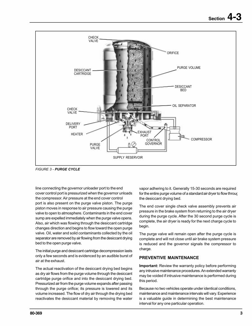
PURGE CYCLE (refer to Figure 3)
When air brake system pressure reaches the cutout settingof the governor, the compressor unloads (air compressionstopped) and the purge cycle of the air dryer begins. The
380-369
Section 4-3
FIGURE 3 - PURGE CYCLE
CONTROLGOVERNOR
SUPPLY RESERVOIR
PURGE VOLUME
DESICCANTBED
OIL SEPARATOR
DESICCANTCARTRIDGE
DELIVERYPORT
HEATER
CHECKVALVE
PURGEVALVE
COMPRESSOR
CHECKVALVE
ORIFICE
EXHAUSTPORT
line connecting the governor unloader port to the endcover control port is pressurized when the governor unloadsthe compressor. Air pressure at the end cover controlport is also present on the purge valve piston. The purgepiston moves in response to air pressure causing the purgevalve to open to atmosphere. Contaminants in the end coversump are expelled immediately when the purge valve opens.Also, air which was flowing through the desiccant cartridgechanges direction and begins to flow toward the open purgevalve. Oil, water and solid contaminants collected by the oilseparator are removed by air flowing from the desiccant dryingbed to the open purge valve.
The initial purge and desiccant cartridge decompression lastsonly a few seconds and is evidenced by an audible burst ofair at the exhaust.
The actual reactivation of the desiccant drying bed beginsas dry air flows from the purge volume through the desiccantcartridge purge orifice and into the desiccant drying bed.Pressurized air from the purge volume expands after passingthrough the purge orifice; its pressure is lowered and itsvolume increased. The flow of dry air through the drying bedreactivates the desiccant material by removing the water
vapor adhering to it. Generally 15-30 seconds are requiredfor the entire purge volume of a standard air dryer to flow througthe desiccant drying bed.
The end cover single check valve assembly prevents airpressure in the brake system from returning to the air dryerduring the purge cycle. After the 30 second purge cycle iscomplete, the air dryer is ready for the next charge cycle tobegin.
The purge valve will remain open after the purge cycle iscomplete and will not close until air brake system pressureis reduced and the governor signals the compressor tocharge.
PREVENTIVE MAINTENANCE
Important: Review the warranty policy before performingany intrusive maintenance procedures. An extended warrantymay be voided if intrusive maintenance is performed duringthis period.
Because no two vehicles operate under identical conditions,maintenance and maintenance intervals will vary. Experienceis a valuable guide in determining the best maintenanceinterval for any one particular operation.
4 80-369
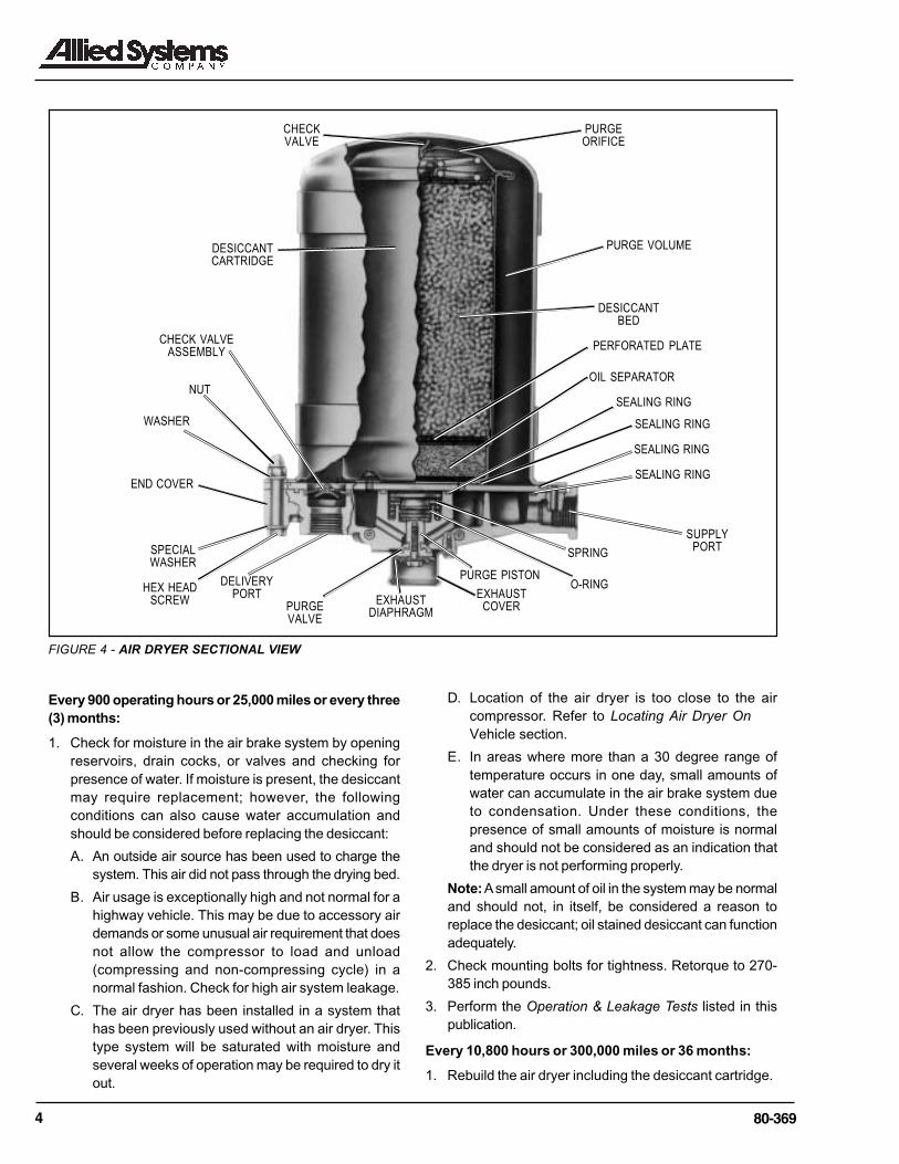
FIGURE 4 - AIR DRYER SECTIONAL VIEW
DESICCANTBED
OIL SEPARATOR
DESICCANTCARTRIDGE
CHECKVALVE
PURGEORIFICE
EXHAUSTCOVER
NUT
CHECK VALVEASSEMBLY
END COVER
HEX HEADSCREW
SPECIALWASHER
DELIVERYPORT
PURGEVALVE
EXHAUSTDIAPHRAGM
O-RINGPURGE PISTON
SPRING
SEALING RING
SEALING RING
SEALING RING
SEALING RING
SUPPLYPORT
PERFORATED PLATE
PURGE VOLUME
WASHER
Every 900 operating hours or 25,000 miles or every three(3) months:
1. Check for moisture in the air brake system by openingreservoirs, drain cocks, or valves and checking forpresence of water. If moisture is present, the desiccantmay require replacement; however, the followingconditions can also cause water accumulation andshould be considered before replacing the desiccant:
A. An outside air source has been used to charge thesystem. This air did not pass through the drying bed.
B. Air usage is exceptionally high and not normal for ahighway vehicle. This may be due to accessory airdemands or some unusual air requirement that doesnot allow the compressor to load and unload(compressing and non-compressing cycle) in anormal fashion. Check for high air system leakage.
C. The air dryer has been installed in a system thathas been previously used without an air dryer. Thistype system will be saturated with moisture andseveral weeks of operation may be required to dry itout.
D. Location of the air dryer is too close to the aircompressor. Refer to Locating Air Dryer OnVehicle section.
E. In areas where more than a 30 degree range oftemperature occurs in one day, small amounts ofwater can accumulate in the air brake system dueto condensation. Under these conditions, thepresence of small amounts of moisture is normaland should not be considered as an indication thatthe dryer is not performing properly.
Note: A small amount of oil in the system may be normaland should not, in itself, be considered a reason toreplace the desiccant; oil stained desiccant can functionadequately.
2. Check mounting bolts for tightness. Retorque to 270-385 inch pounds.
3. Perform the Operation & Leakage Tests listed in thispublication.
Every 10,800 hours or 300,000 miles or 36 months:
1. Rebuild the air dryer including the desiccant cartridge.
580-369
Section 4-3Note: The desiccant change interval may vary from vehicleto vehicle. Although typical desiccant cartridge life is threeyears, many will perform adequately for a longer period oftime. In order to take maximum advantage of desiccant lifeand assure that replacement occurs only when necessary,it is important that Operation & Leakage Tests be performed.
WARNING!
This air dryer is intended to remove moisture and othercontaminants normally found in the air brake system. Donot inject alcohol, anti-freeze, or other de-icing substancesinto or upstream of the air dryer. Alcohol is removed by thedryer, but reduces the effectiveness of the device to dry air.Use of other substances can damage the air dryer and mayvoid the warranty.
OPERATION & LEAKAGE TESTS
1. Test the outlet port check valve assembly by buildingthe air system to governor cut-out and observing a testair gauge installed in the supply reservoir. A rapid loss ofpressure could indicate a failed outlet port check valve.(Note: Purge valve will be open when governor cut-outpressure is reached. Allow 45 seconds after governorcut-out occurs to complete the purge cycle before testingthe check valve.) Coat the exhaust with a soap solution.Leakage should not exceed a 1 inch bubble in 1 second.
2. Check for excessive leakage around the purge valve.With the compressor in loaded mode (compressing air),apply a soap solution to the purge valve housingassembly exhaust port and observe that leakage doesnot exceed a 1 inch bubble in 1 second. If the leakageexceeds the maximum specified, service the purge valvehousing assembly.
3. Close all reservoir drain cocks. Build up system pressureto governor cut-out and note that purges with anaudible escape of air. “Fan” the service brakes to reducesystem air pressure to governor cut-in. Note that thesystem once again builds to full pressure and is followedby an purge.
4. Check the operation of the safety valve by pulling theexposed stem while the compressor is loaded(compressing air). There must be an exhaust of air whilethe stem is held and the valve should reseat when thestem is released.
5. Check all lines and fittings leading to and from the airdryer for leakage and integrity.
6. Check the operation of the end cover heater andthermostat assembly during cold weather operation asfollows:
A. Electric Power to the Dryer
With the ignition or engine kill switch in the ONposition, check for power at the dryer’s electricalterminal using a voltmeter or test light. On a single
terminal disconnect the lead wire at the endcover terminal post. Place the test leads on the leadwire and a GOOD vehicle ground. On dual terminaldisconnect both lead wires at the end coverterminal posts. If there is no voltage indicated, lookfor a blown fuse, broken wires, or corrosion in thevehicle wiring harness. Check to see if a good groundpath exists.
B. Thermostat and Heater Operation
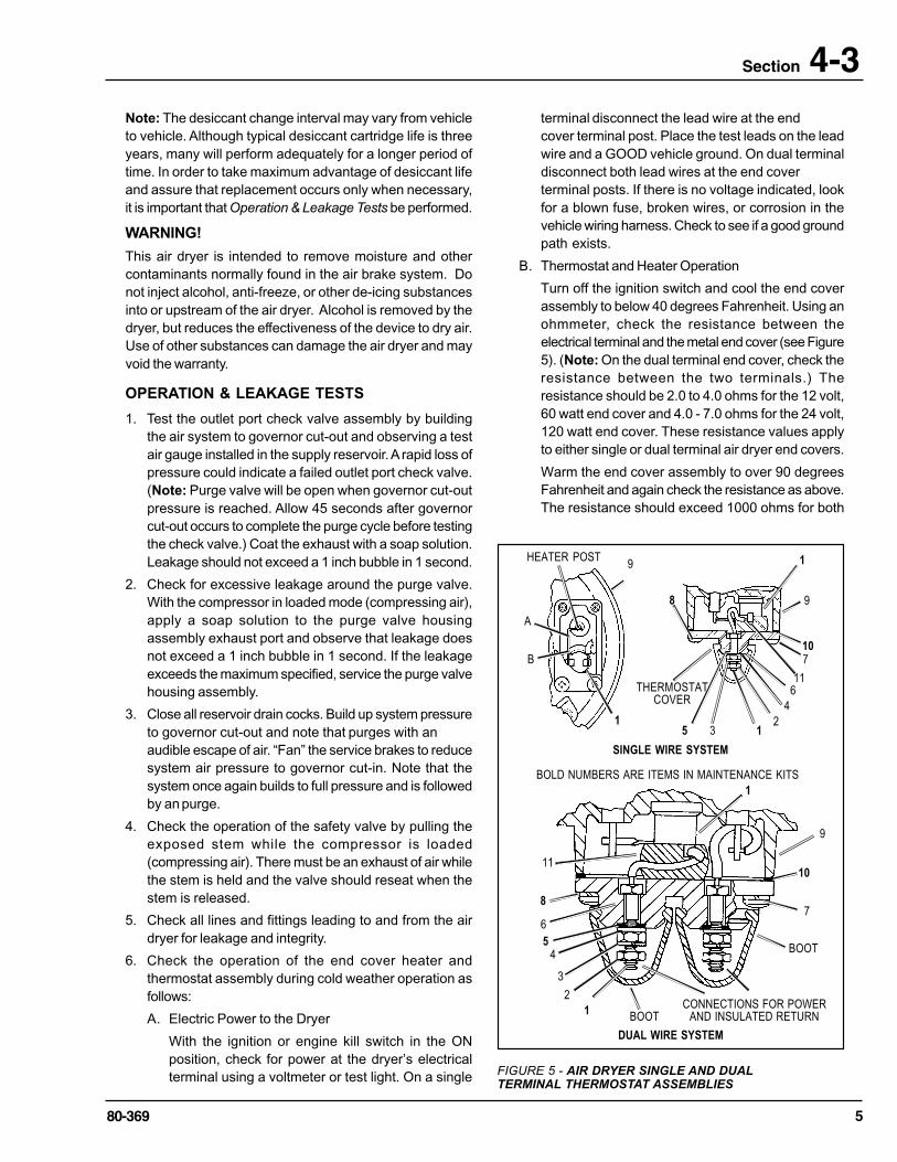
Turn off the ignition switch and cool the end coverassembly to below 40 degrees Fahrenheit. Using anohmmeter, check the resistance between theelectrical terminal and the metal end cover (see Figure5). (Note: On the dual terminal end cover, check theresistance between the two terminals.) Theresistance should be 2.0 to 4.0 ohms for the 12 volt,60 watt end cover and 4.0 - 7.0 ohms for the 24 volt,120 watt end cover. These resistance values applyto either single or dual terminal air dryer end covers.
Warm the end cover assembly to over 90 degreesFahrenheit and again check the resistance as above.The resistance should exceed 1000 ohms for both
FIGURE 5 - AIR DRYER SINGLE AND DUALTERMINAL THERMOSTAT ASSEMBLIES
DUAL WIRE SYSTEM
BOOT
7
10
9
1
11
8
6
1CONNECTIONS FOR POWER
AND INSULATED RETURNBOOT
3
2
45
BOLD NUMBERS ARE ITEMS IN MAINTENANCE KITS
SINGLE WIRE SYSTEM
1
98
1
9
21
4
611
710
THERMOSTATCOVER
5 3
A
B
HEATER POST

6 80-369
single and dual terminal air dryers. If the resistancevalues obtained are within the stated limits, thethermostat and heater assembly is operating properly.If the resistance values obtained are outside thestated limits, proceed to Step C to determine thecause.
C. Heater Element Inspection
With the ignition or engine control switch “off”, removethe thermostat cover (see Figure 5). Using anohmmeter, check the resistance between the metalend cover and the heater post (see Figure 5). (Note:On the dual terminal end cover, check the resistancebetween the two terminals.) For a 12 volt, 60 wattend cover, the resistance should be 2.0 - 2.8 ohmsand for a 24 volt, 120 watt end cover, 4.0 - 5.6 ohms.These resistance values apply to either single or dualterminal air dryer end covers. If the heater resistancevalue obtained is outside the stated limits, a new orremanufactured end cover should be installed, sincethe heater element cannot be serviced. Check thata good ground path exists between the air dryer endcover casting and the vehicle chassis. Correct ifneeded. If the heater resistance value obtained iswithin the stated limits the thermostat should bereplaced (Kit Number 231544) or a new orremanufactured end cover installed.
D. Reassembly
Reinstall the thermostat cover as illustrated in Figure5. Take special care to assure the rubber spacerand the gasket are correctly installed, to assureproper operation.
REBUILDING THE AIR DRYER
GENERAL
If, after completing the routine operation and leakage tests,it has been determined that one or more components of theair dryer requires replacement or maintenance, refer to thefollowing list to find the appropriate kit(s).
When rebuilding or replacing components of the air dryeruse only genuine parts. For ease in servicing thedesiccant cartridge assembly, it is recommended thatthe air dryer be removed from the vehicle.
MAINTENANCE KITS AVAILABLE:
231539 Major Maintenance KitThis kit contains the parts necessary to completelyrebuild the Air Dryer (desiccant cartridgeincluded) and includes kit 231541.
231543 Purge Valve Maintenance KitThis kit contains the parts necessary to rebuild theend cover purge valve only.
231542 Seal KitThis kit contains the outlet port check valve and theo-rings and seals required when removing the endcover assembly. This kit is included with kits 231541and 231540.
231541 End Cover Maintenance KitThis kit contains the parts necessary to rebuild theend cover of the Air Dryer and includes kit231543.
231540 Desiccant Cartridge Replacement KitThis kit contains the parts necessary to changethe desiccant cartridge only.
231544 Thermostat Maintenance Kit (single terminalmodels)This kit contains the parts necessary to rebuild asingle terminal thermostat assembly in the Air Dryer.Thermostat Maintenance Kit (dual terminalmodels)This kit contains the parts necessary to rebuild atwo terminal thermostat assembly (insulatedground).Thermostat Cover Replacement Kit (singleterminal models)This kit contains the necessary components forreplacing the non-metallic thermostat cover.Thermostat Cover Replacement Kit (dual terminalmodels)This kit contains the necessary components forreplacing the non-metallic thermostat cover.
IMPORTANT! PLEASE READ
When working on or around a vehicle, the followinggeneral precautions should be observed:
1. Park the vehicle on a level surface, apply theparking brakes, and always block the wheels.
2. Stop the engine when working around the vehicle.
3. If the vehicle is equipped with air brakes, makecertain to drain the air pressure from all reservoirsbefore beginning ANY work on the vehicle.
4. Following the vehicle manufacturer’srecommended procedures, deactivate the electricalsystem in a manner that removes all electricalpower from the vehicle.
5. When working in the engine compartment theengine should be shut off. Where circumstancesrequire that the engine be in operation, EXTREMECAUTION should be used to prevent personal injuryresulting from contact with moving, rotating,leaking, heated, or electrically chargedcomponents.
6. Never connect or disconnect a hose or linecontaining pressure; it may whip. Never remove acomponent or plug unless you are certain allsystem pressure has been depleted.
780-369
Section 4-3
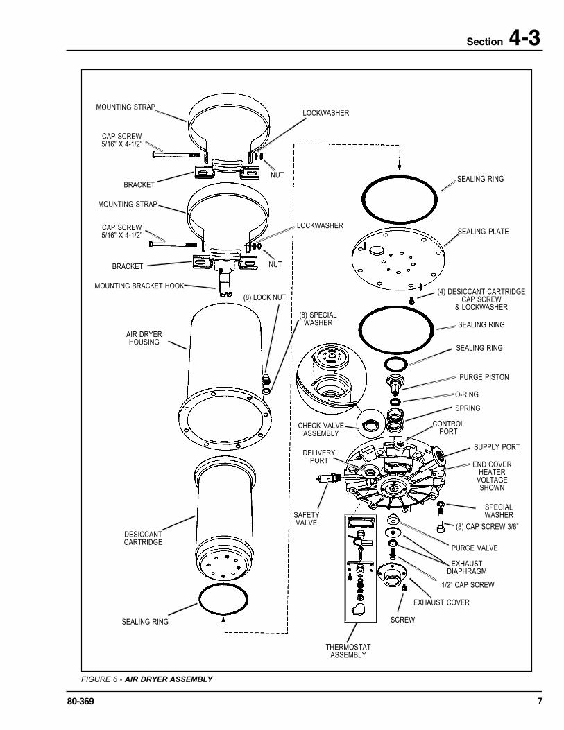
FIGURE 6 - AIR DRYER ASSEMBLY
AIR DRYERHOUSING
THERMOSTATASSEMBLY
SAFETYVALVE
CHECK VALVEASSEMBLY
SCREW
EXHAUST COVER
1/2” CAP SCREW
PURGE VALVE
(8) CAP SCREW 3/8”
SEALING RING
SEALING PLATE
(4) DESICCANT CARTRIDGECAP SCREW
& LOCKWASHER
SEALING RING
SEALING RING
END COVERHEATER
VOLTAGESHOWN
SUPPLY PORT
CONTROLPORT
SPRING
O-RING
PURGE PISTON
SPECIALWASHER
EXHAUSTDIAPHRAGM
DELIVERYPORT
BRACKET
MOUNTING STRAP
CAP SCREW5/16” X 4-1/2”
BRACKET
MOUNTING STRAP
CAP SCREW5/16” X 4-1/2”
LOCKWASHER
NUT
LOCKWASHER
NUT
MOUNTING BRACKET HOOK
(8) LOCK NUT
(8) SPECIALWASHER
DESICCANTCARTRIDGE
SEALING RING
8 80-369
7. Never exceed recommended pressures and alwayswear safety glasses.
8. Do not attempt to install, remove, disassemble orassemble a component until you have read andthoroughly understand the recommendedprocedures. Use only the proper tools and observeall precautions pertaining to use of those tools.
9. Use only genuine replacement parts,components, and kits. Replacement hardware,tubing, hose, fittings, etc. should be of equivalentsize, type, and strength as original equipment andbe designed specifically for such applications andsystems.
10. Components with stripped threads or damagedparts should be replaced rather than repaired.Repairs requiring machining or welding should notbe at tempted unless specifically approved andstated by the vehicle or component manufacturer.
11. Prior to returning the vehicle to service, makecertain all components and systems are restoredto their proper operating condition.
REMOVAL
1. Park the vehicle on a level surface and prevent movementby means other than the brakes.
2. Drain all reservoirs to 0 p.s.i. (0 kPa).— Caution:Compressor discharge line may still contain residualpressure.
3. Identify and disconnect the three air lines from the endcover and note the position of end cover ports relative tothe vehicle.
4. Pull boot from the thermostat and heater cover and slideit onto the wire to expose the connection. Remove nutand disconnect electrical wire from the terminal. Note:Vehicles with insulated ground (2 wire) system will havetwo boots and two terminals to be disconnected. (SeeFigures 5 & 8.)
5. Loosen the 5/16" X 4-1/2" hex bolt securing the upperand lower mounting straps. Disengage the mountingbracket hook from the end cover (Refer to Figure 6.)Note: If the air dryer being serviced has a right angle bracket instead of a lower mounting strap and safetyhook, proceed to step 6, otherwise proceed to step 7.
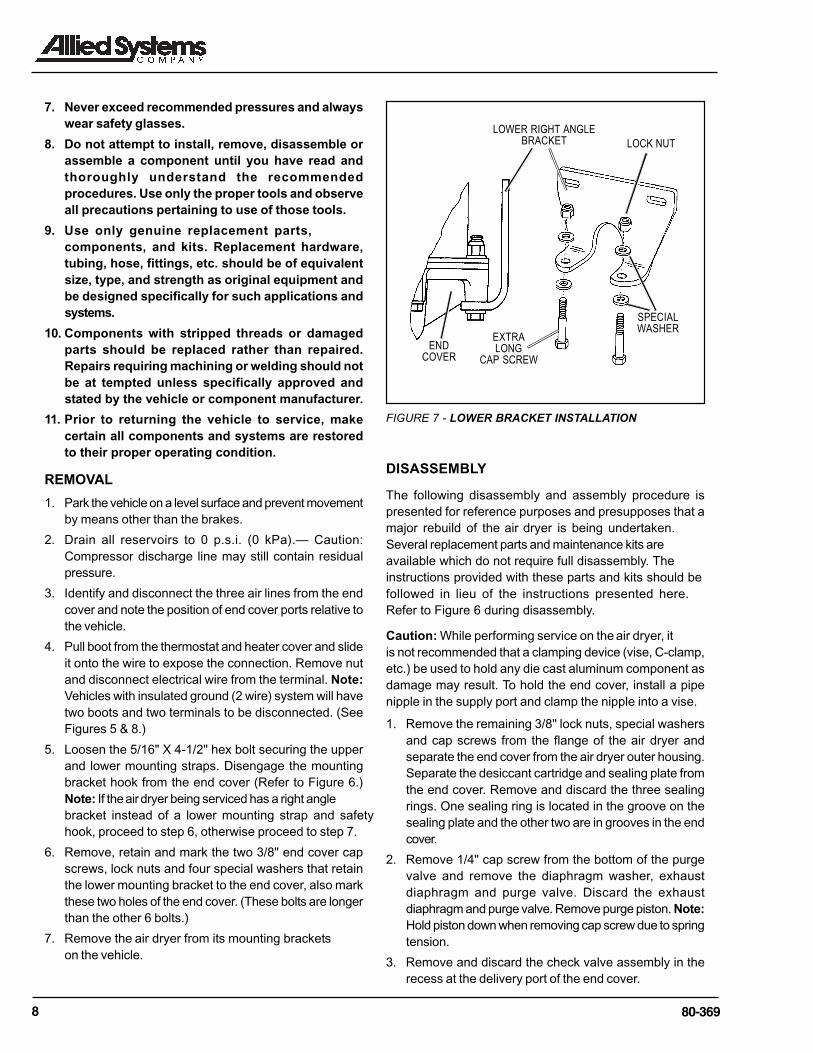
6. Remove, retain and mark the two 3/8" end cover capscrews, lock nuts and four special washers that retainthe lower mounting bracket to the end cover, also markthese two holes of the end cover. (These bolts are longerthan the other 6 bolts.)
7. Remove the air dryer from its mounting bracketson the vehicle.
ENDCOVER
SPECIALWASHER
LOCK NUT
LOWER RIGHT ANGLEBRACKET
EXTRALONG
CAP SCREW
DISASSEMBLY
The following disassembly and assembly procedure ispresented for reference purposes and presupposes that amajor rebuild of the air dryer is being undertaken. Several replacement parts and maintenance kits are available which do not require full disassembly. The instructions provided with these parts and kits should be followed in lieu of the instructions presented here. Refer to Figure 6 during disassembly.
Caution: While performing service on the air dryer, itis not recommended that a clamping device (vise, C-clamp,etc.) be used to hold any die cast aluminum component asdamage may result. To hold the end cover, install a pipenipple in the supply port and clamp the nipple into a vise.
1. Remove the remaining 3/8" lock nuts, special washersand cap screws from the flange of the air dryer andseparate the end cover from the air dryer outer housing.Separate the desiccant cartridge and sealing plate fromthe end cover. Remove and discard the three sealingrings. One sealing ring is located in the groove on thesealing plate and the other two are in grooves in the endcover.
2. Remove 1/4" cap screw from the bottom of the purgevalve and remove the diaphragm washer, exhaustdiaphragm and purge valve. Discard the exhaustdiaphragm and purge valve. Remove purge piston. Note:Hold piston down when removing cap screw due to springtension.
3. Remove and discard the check valve assembly in therecess at the delivery port of the end cover.
FIGURE 7 - LOWER BRACKET INSTALLATION
980-369
Section 4-34. Remove the safety valve from the end cover (only if it has
been determined that it needs replacement during servicechecks).
5. To remove the thermostat see the appropriate section inthis manual (only if it has been determined that it needsreplacement during service checks).
6. Remove purge piston and spring from the top side of thecover.
7. Remove o-ring from the purge piston and discard the o-ring.
8. Remove the four 1/4" cap screws and lockwashers thatsecure the sealing plate to the desiccant cartridge.Separate the sealing plate from the desiccant cartridgeand discard the sealing ring at the base of the cartridge.
CLEANING & INSPECTION
1. Using mineral spirits or an equivalent solvent, clean andthoroughly dry all metal parts.
2. Inspect the interior and exterior of all metal parts thatwill be reused for severe corrosion, pitting and cracks.Superficial corrosion and or pitting on the exterior portionof the upper and lower body halves is acceptable.
3. Inspect the bores of both the end cover for deep scuffingor gouges.
4. Make certain that all purge valve housing and end coverpassages are open and free of obstructions.
5. Inspect the pipe threads in the end cover. Make certainthey are clean and free of thread sealant.
1&9
7
5
6
DELIVERYPORT
MOUNTINGBRACKET
HOOK
SAFETYVALVE
2
CONTROLPORT
HEATERVOLTS/WATTS
EMBOSSEDHERE
8
3
SUPPLYPORT
4
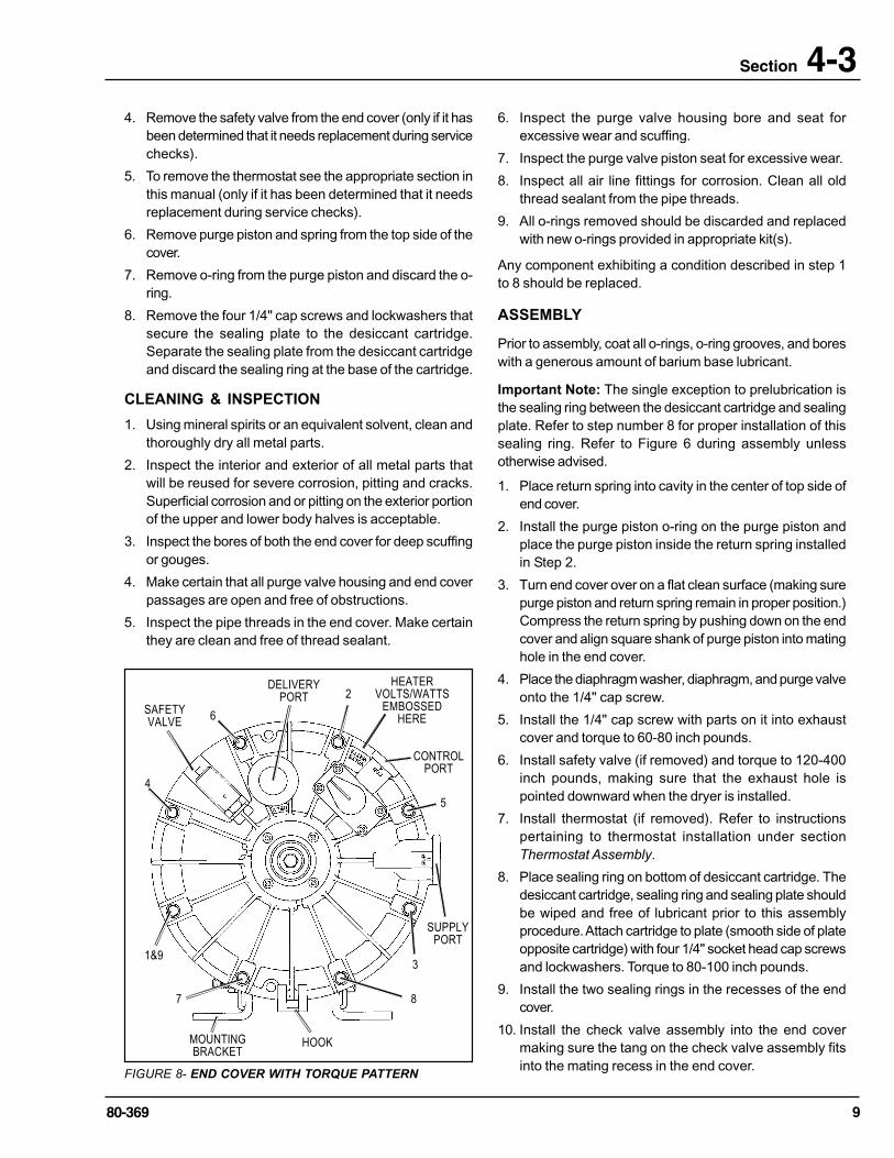
FIGURE 8- END COVER WITH TORQUE PATTERN
6. Inspect the purge valve housing bore and seat forexcessive wear and scuffing.
7. Inspect the purge valve piston seat for excessive wear.
8. Inspect all air line fittings for corrosion. Clean all oldthread sealant from the pipe threads.
9. All o-rings removed should be discarded and replacedwith new o-rings provided in appropriate kit(s).
Any component exhibiting a condition described in step 1to 8 should be replaced.
ASSEMBLY
Prior to assembly, coat all o-rings, o-ring grooves, and boreswith a generous amount of barium base lubricant.
Important Note: The single exception to prelubrication isthe sealing ring between the desiccant cartridge and sealingplate. Refer to step number 8 for proper installation of thissealing ring. Refer to Figure 6 during assembly unlessotherwise advised.
1. Place return spring into cavity in the center of top side ofend cover.
2. Install the purge piston o-ring on the purge piston andplace the purge piston inside the return spring installedin Step 2.
3. Turn end cover over on a flat clean surface (making surepurge piston and return spring remain in proper position.)Compress the return spring by pushing down on the endcover and align square shank of purge piston into matinghole in the end cover.
4. Place the diaphragm washer, diaphragm, and purge valveonto the 1/4" cap screw.
5. Install the 1/4" cap screw with parts on it into exhaustcover and torque to 60-80 inch pounds.
6. Install safety valve (if removed) and torque to 120-400inch pounds, making sure that the exhaust hole ispointed downward when the dryer is installed.
7. Install thermostat (if removed). Refer to instructionspertaining to thermostat installation under sectionThermostat Assembly.
8. Place sealing ring on bottom of desiccant cartridge. Thedesiccant cartridge, sealing ring and sealing plate shouldbe wiped and free of lubricant prior to this assemblyprocedure. Attach cartridge to plate (smooth side of plateopposite cartridge) with four 1/4" socket head cap screwsand lockwashers. Torque to 80-100 inch pounds.
9. Install the two sealing rings in the recesses of the endcover.
10. Install the check valve assembly into the end covermaking sure the tang on the check valve assembly fitsinto the mating recess in the end cover.
10 80-369
11. Place desiccant cartridge and sealing plate assemblyonto end cover. (Taking care not to displace sealing rings.)The large hole in the sealing plate must line up with thecheck valve and spiral pins in the sealing plate mustenter corresponding holes in the end cover.
12. Install the outer sealing ring on the sealing plate. Placethe outer housing over the desiccant cartridge (lining upmarks made on the outer housing and end cover prior todisassembly) and retain with eight 3/8" hex head bolts,special washers, and lock nuts. Refer to Figure 8 fortorque pattern. Torque to 270-385 inch pounds. Note: If3/8" bolts require replacement, insure that thereplacement bolts are grade 5 minimum and the samelength as the original bolts. Use of inferior bolts cancompromise the integrity of the air dryer and lead topremature failure. Where a lower, right angle mountingbracket (instead of a lower mounting strap) is used; lineup the marks made on the outer housing and end cover.Install the six (standard) 3/8" cap screws, lock nuts andtwelve special washers. The two longer 3/8" cap screwswill be used to secure the air dryer to the rightangle mounting bracket.
Note: If during the Operation & Leakage Tests it wasdetermined that the thermostat was inoperative, use thefollowing procedure for repair or replacement. It is notnecessary to replace this unit each time the end coveris rebuilt. Use thermostat maintenance kit 102657 forsingle terminal application. For dual terminal application,use kit #103982. (See Figure 5.)
THERMOSTAT DISASSEMBLY (Refer to Figures 5and 8)
1. Remove nut (2), then lockwasher (3), plain washer (4),nut (2) and o-rings (5). Discard o-ring and retain otherparts.
2. Remove and retain four Phillips head screws (7) andcover (6).
3. Remove and discard gasket (10).
4. Remove and retain spacer (11).
5. Cut uninsulated thermostat wire at Point B, remove anddiscard thermostat and terminal assembly (1).
6. Clean remaining wire attached to heater terminal.
7. Clean thermostat “pocket” in end cover (9).
THERMOSTAT ASSEMBLY (Refer to Figure 5)
1. Cut uninsulated lead of new thermostat (1) at Point A.
2. Install thermostat in end cover pocket and positionuninsulated leads next to each other.
3. Using a soldering heat sink, clamp uninsulated leads atPoint B and solder leads with straight rosin core solder.Do not use acid core solder as corrosion can result.Clean excess solder off end cover.
4. Install thermostat terminal (1) in cover (6).
5. Install o-ring (5), washer (4), and nut (2). Torque nut to20-30 inch pounds. Then install lockwasher (3) and nut(2) finger tight to allow for reconnection of electrical wirewhen reinstalled on vehicle.
6. Install spacer (11) over thermostat (1).
7. Install gasket (7) and thermostat cover (6) and securethermostat cover to end cover (9) using screws (7) andlockwashers (8).
8. Torque to 20-30 inch pounds.
9. Test thermostat as follows:
A. At a temperature above 90 degrees Fahrenheit,check resistance between thermostat terminal (1)and end cover (9). Resistance should be 1,000 ohmsor greater; if not, check for solder “path” short.
B. Chill entire end cover assembly to 40 degreesFahrenheit or below and check resistance again.Resistance should be 2-4 ohms for a 12 volt, 60 wattend cover and 4-7 ohms for a 24 volt, 120 watt endcover.
1180-369
Section 4-3
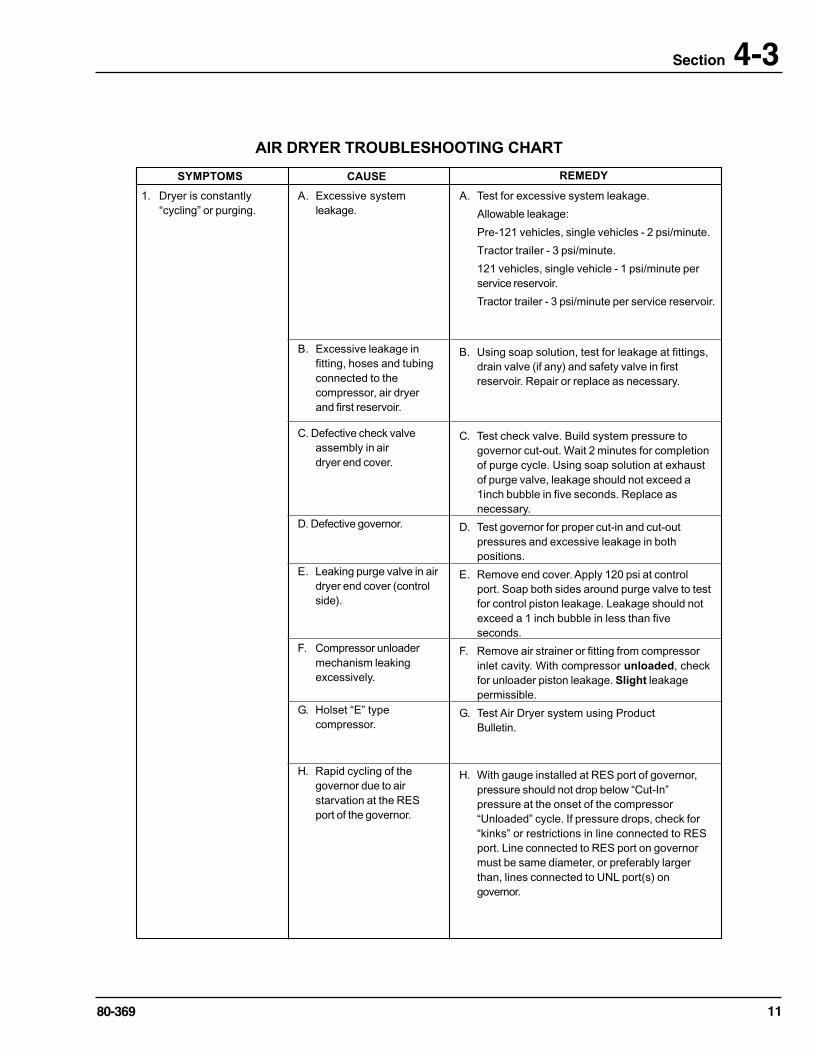
AIR DRYER TROUBLESHOOTING CHART
SYMPTOMS
1. Dryer is constantly“cycling” or purging.
A. Test for excessive system leakage.
Allowable leakage:
Pre-121 vehicles, single vehicles - 2 psi/minute.
Tractor trailer - 3 psi/minute.
121 vehicles, single vehicle - 1 psi/minute perservice reservoir.
Tractor trailer - 3 psi/minute per service reservoir.
A. Excessive systemleakage.
B. Excessive leakage infitting, hoses and tubingconnected to thecompressor, air dryerand first reservoir.
CAUSE REMEDY
C. Defective check valveassembly in airdryer end cover.
D. Defective governor.
E. Leaking purge valve in airdryer end cover (controlside).
F. Compressor unloadermechanism leakingexcessively.
G. Holset “E” typecompressor.
H. Rapid cycling of thegovernor due to airstarvation at the RESport of the governor.
B. Using soap solution, test for leakage at fittings,drain valve (if any) and safety valve in firstreservoir. Repair or replace as necessary.
C. Test check valve. Build system pressure togovernor cut-out. Wait 2 minutes for completionof purge cycle. Using soap solution at exhaustof purge valve, leakage should not exceed a1inch bubble in five seconds. Replace asnecessary.
D. Test governor for proper cut-in and cut-outpressures and excessive leakage in bothpositions.
E. Remove end cover. Apply 120 psi at controlport. Soap both sides around purge valve to testfor control piston leakage. Leakage should notexceed a 1 inch bubble in less than fiveseconds.
F. Remove air strainer or fitting from compressorinlet cavity. With compressor unloaded, checkfor unloader piston leakage. Slight leakagepermissible.
G. Test Air Dryer system using ProductBulletin.
H. With gauge installed at RES port of governor,pressure should not drop below “Cut-In”pressure at the onset of the compressor“Unloaded” cycle. If pressure drops, check for“kinks” or restrictions in line connected to RESport. Line connected to RES port on governormust be same diameter, or preferably largerthan, lines connected to UNL port(s) ongovernor.
12 80-369
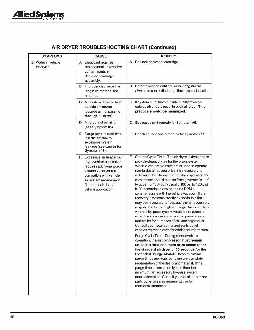
AIR DRYER TROUBLESHOOTING CHART (Continued)
SYMPTOMS
2. Water in vehiclereservoir.
A. Desiccant requiresreplacement - excessivecontaminants indesiccant cartridgeassembly.
B. Improper discharge linelength or improper linematerial.
CAUSE REMEDY
E. Purge (air exhaust) timeinsufficient due toexcessive systemleakage (see causes forSymptom #1).
C. Air system charged fromoutside air source(outside air not passingthrough air dryer).
D. Air dryer not purging(see Symptom #5).
F. Excessive air usage - Airdryer/vehicle applicationrequires additional purgevolume. Air dryer notcompatible with vehicleair system requirement(Improper air dryer/vehicle application).
A. Replace desiccant cartridge.
B. Refer to section entitled Connecting the AirLines and check discharge line size and length.
C. If system must have outside air fill provision,outside air should pass through air dryer. Thispractice should be minimized.
D. See cause and remedy for Symptom #5.
E. Check causes and remedies for Symptom #1.
F. Charge Cycle Time - The air dryer is designed toprovide clean, dry air for the brake system.When a vehicle’s air system is used to operatenon-brake air accessories it is necessary todetermine that during normal, daily operation thecompressor should recover from governor “cut-in”to governor “cut-out” (usually 100 psi to 120 psi)in 90 seconds or less at engine RPM’scommensurate with the vehicle vocation. If therecovery time consistently exceeds this limit, itmay be necessary to “bypass” the air accessoryresponsible for the high air usage. An example ofwhere a by-pass system would be required iswhen the compressor is used to pressurize atank trailer for purposes of off-loading product.Consult your local authorized parts outletor sales representative for additional information.
Purge Cycle Time - During normal vehicleoperation, the air compressor must remainunloaded for a minimum of 20 seconds forthe standard air dryer or 30 seconds for theExtended Purge Model. These minimumpurge times are required to ensure completeregeneration of the desiccant material. If thepurge time is consistently less than theminimum, an accessory by-pass systemmustbe installed. Consult your local authorizedparts outlet or sales representative foradditional information.
1380-369
Section 4-3
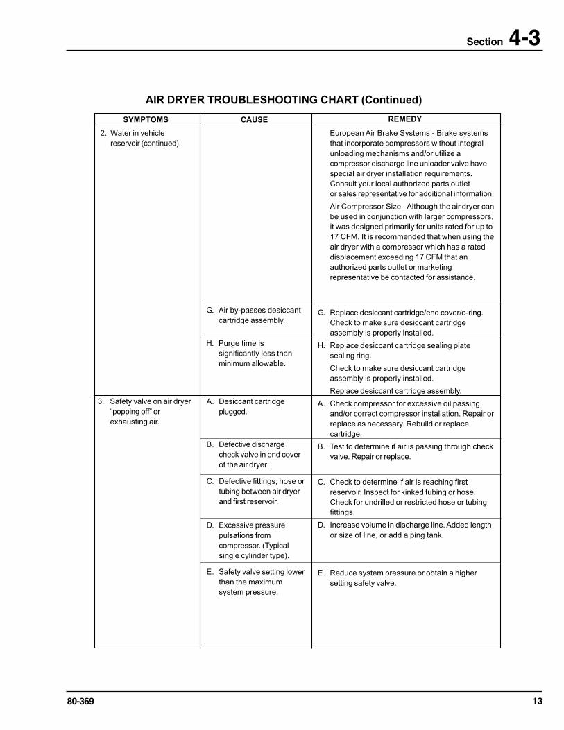
AIR DRYER TROUBLESHOOTING CHART (Continued)
SYMPTOMS
2. Water in vehiclereservoir (continued).
European Air Brake Systems - Brake systemsthat incorporate compressors without integralunloading mechanisms and/or utilize acompressor discharge line unloader valve havespecial air dryer installation requirements.Consult your local authorized parts outletor sales representative for additional information.
Air Compressor Size - Although the air dryer canbe used in conjunction with larger compressors,it was designed primarily for units rated for up to17 CFM. It is recommended that when using theair dryer with a compressor which has a rateddisplacement exceeding 17 CFM that anauthorized parts outlet or marketingrepresentative be contacted for assistance.
G. Replace desiccant cartridge/end cover/o-ring.Check to make sure desiccant cartridgeassembly is properly installed.
H. Replace desiccant cartridge sealing platesealing ring.
Check to make sure desiccant cartridgeassembly is properly installed.
Replace desiccant cartridge assembly.
A. Check compressor for excessive oil passingand/or correct compressor installation. Repair orreplace as necessary. Rebuild or replacecartridge.
B. Test to determine if air is passing through checkvalve. Repair or replace.
C. Check to determine if air is reaching firstreservoir. Inspect for kinked tubing or hose.Check for undrilled or restricted hose or tubingfittings.
D. Increase volume in discharge line. Added lengthor size of line, or add a ping tank.
E. Reduce system pressure or obtain a highersetting safety valve.
CAUSE REMEDY
G. Air by-passes desiccantcartridge assembly.
H. Purge time issignificantly less thanminimum allowable.
3. Safety valve on air dryer“popping off” orexhausting air.
A. Desiccant cartridgeplugged.
B. Defective dischargecheck valve in end coverof the air dryer.
C. Defective fittings, hose ortubing between air dryerand first reservoir.
D. Excessive pressurepulsations fromcompressor. (Typicalsingle cylinder type).
E. Safety valve setting lowerthan the maximumsystem pressure.

14 80-369
AIR DRYER TROUBLESHOOTING CHART (Continued)
SYMPTOMS
4. Constant exhaust of airat air dryer purge valveexhaust or unable tobuild system pressure.(Charge mode.)
A. With compressor loaded, apply soap solution onpurge valve exhaust, to test for excessiveleakage. Repair purge valve as necessary.
B. Check governor for proper “cut-in”, “cut-out”pressure and excessive leakage in bothpositions. Repair or replace as necessary.
C. Purge control line must be connected tounloader port of governor.
D. Test heater and thermostat as described in Step7 of Preventative Maintenance Section.
E. Compressor discharge to inlet port. Reconnectlines properly.
F. Test check valve for proper operation (seeSymptom #3, Remedy B).
G. Check to determine if air passes throughdischarge line. Check for kinks, bends,excessive carbon deposits.
H. Discharge line should be constantly sloping fromcompressor to air dryer with as few bends aspossible.
A. Test to determine air flows through purge controlline when compressor unloaded. Check forundrilled fittings. (See Symptom #4, Remedy C.)
B. After determining air reaches purge valve(Remedy A above), repair purge valve.
C. Refer to Remedies B, E, F, G, H, for Symptom#4.
A. Air dryer purge valveleaking excessively.
CAUSE REMEDY
5. Air dryer does not purgeor exhaust air.
B. Defective governor.
C. Purge control lineconnected to reservoir orexhaust port of governor.
D. Purge valve frozen open -faulty heater andthermostat, wiring, blownfuse.
E. Inlet and outlet airconnections reversed.
F. Check valve between airdryer and first reservoirdefective.
A. Broken, kinked, frozen,plugged or disconnectedpurge control line.
B. Faulty air dryer purgevalve.
C. See Causes, B. E, F, G,H, for Symptom #4.
6. Desiccant materialbeing expelled from airdryer purge valveexhaust (may look likewhitish liquid or pasteor small beads.)
- OR -
Unsatisfactorydesiccant life.
A. This symptom is almostalways accompanied byone or more ofSymptoms 1, 2, 3, 4 and5. See related causes forthese Symptoms above.
B. Air dryer not securelymounted. (Excessivevibration.)
A. See Causes and Remedies for Symptoms 1, 2,3, 4 and 5.
B. Vibration should be held to minimum. Addbracket supports or change air dryer mountinglocation if necessary.
G. Kinked or blocked(plugged) discharge line.
H. Excessive bends indischarge line (watercollects and freezes).
1580-369
Section 4-3
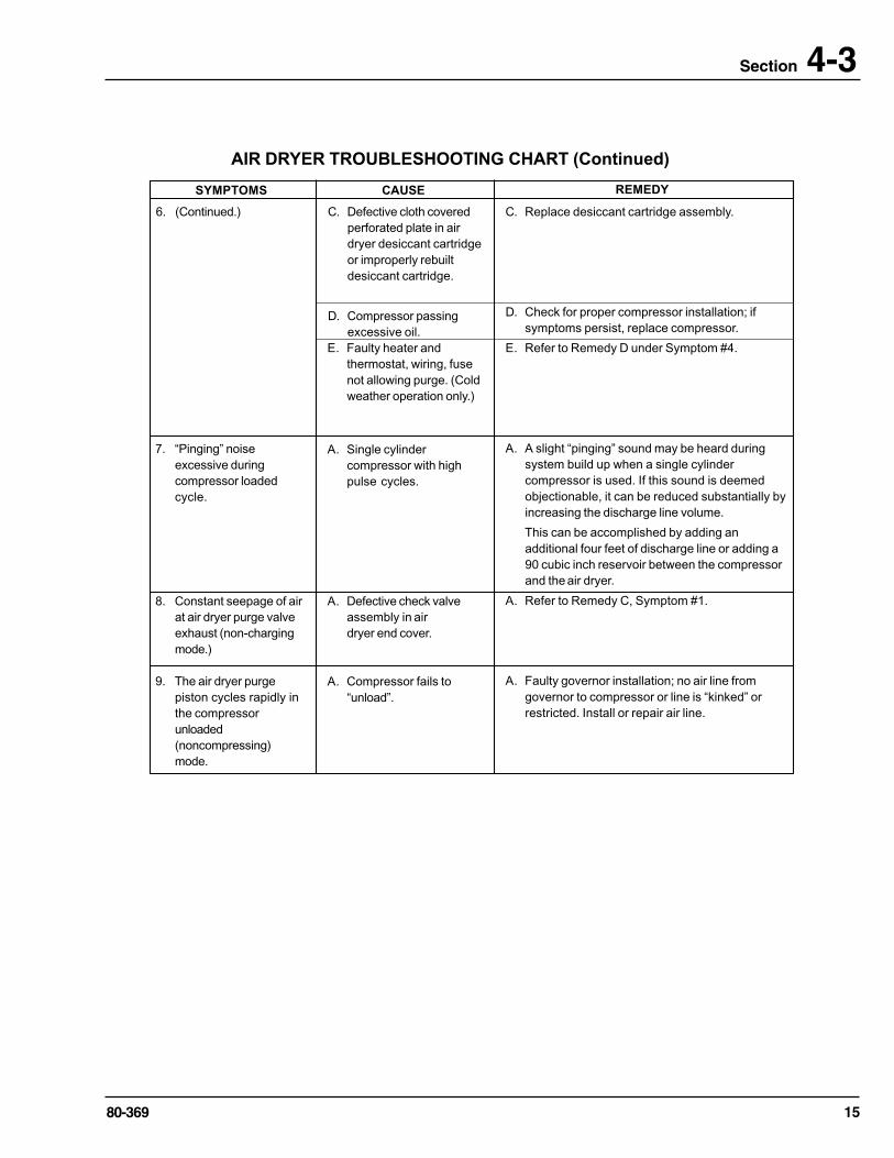
AIR DRYER TROUBLESHOOTING CHART (Continued)
SYMPTOMS
6. (Continued.) C. Replace desiccant cartridge assembly.
D. Check for proper compressor installation; ifsymptoms persist, replace compressor.
E. Refer to Remedy D under Symptom #4.
A. A slight “pinging” sound may be heard duringsystem build up when a single cylindercompressor is used. If this sound is deemedobjectionable, it can be reduced substantially byincreasing the discharge line volume.
This can be accomplished by adding anadditional four feet of discharge line or adding a90 cubic inch reservoir between the compressorand the air dryer.
A. Refer to Remedy C, Symptom #1.
A. Faulty governor installation; no air line fromgovernor to compressor or line is “kinked” orrestricted. Install or repair air line.
C. Defective cloth coveredperforated plate in airdryer desiccant cartridgeor improperly rebuiltdesiccant cartridge.
D. Compressor passingexcessive oil.
CAUSE REMEDY
7. “Pinging” noiseexcessive duringcompressor loadedcycle.
E. Faulty heater andthermostat, wiring, fusenot allowing purge. (Coldweather operation only.)
A. Single cylindercompressor with highpulse cycles.
A. Defective check valveassembly in airdryer end cover.
8. Constant seepage of airat air dryer purge valveexhaust (non-chargingmode.)
A. Compressor fails to“unload”.
9. The air dryer purgepiston cycles rapidly inthe compressorunloaded(noncompressing)mode.
Recommended