SEL-300G
MULTIFUNCTION GENERATOR RELAY
INSTRUCTION MANUAL
SCHWEITZER ENGINEERING LABORATORIES 2350 NE HOPKINS COURT PULLMAN, WA USA 99163-5603 TEL: (509) 332-1890 FAX: (509) 332-7990
!
WARNING: This device is shipped with default passwords. Default passwords should be changed to private passwords at installation. Failure to change each default password to a private password may allow unauthorized access. SEL shall not be responsible for any damage resulting from unauthorized access.
!
ADVERTISSEMENT: Cet appareil est expédié avec des mots de passe par défaut. A l'installation, les mots de passe par défaut devront être changés pour des mots de passe confidentiels. Dans le cas contraire, un accès non-autorisé à l'équipement pourrait être possible. SEL décline toute responsabilité pour tout dommage résultant de cet accès non-autorisé.
!
CAUTION: Be sure to follow the generator and prime mover manufacturers guidelines with respect to generator operation and commissioning.
! ATTENTION: Suivez attentivement les instructions des manufacturiers de la turbine et de la génératrice pour la réception, la mise en route et l'opération.
!
CAUTION: Do not apply reverse polarity dc voltage or ac voltage to terminals Z25 and Z26 of SEL-300G Relays rated for 24/48 Vdc applications. Relay failure and permanent power supply damage will result from application of reverse polarity dc voltage to relays rated for 24/48 Vdc applications.
!
ATTENTION: Nappliquer pas un voltage CC avec polarité inversée ou un voltage CA, sur les bornes Z35 et Z26 des relais 300G dont la tension dalimentation nominale est 24/48 VCC. Une perte de fonctionnement du relais et un bris permanent de lalimentation résulteraient de lapplication dune polarité CC inversée sur un relais avec tension nominale de 24/48 VCC.
!
CAUTION: Standard SEL relay output contacts are rated to make and carry trip coil current, but are not rated to interrupt trip coil current. Do not exceed the contact interrupt ratings shown in Relay Specifications and Options.
!
ATTENTION: Les contacts standards des relais SEL ont la capacité de fermer sur le courant spécifié des bobines douverture mais ne peuvent ouvrir sur le même courant. Il est important de ne pas dépasser les capacités des contacts indiquées an paragraphe Spécifications du Relais et Options.
!
CAUTION: The relay contains devices sensitive to electrostatic discharge (ESD). When working on the relay with front or top cover removed, work surfaces and personnel must be properly grounded or equipment damage may result.
!
ATTENTION: Le relais contient des pièces sensibles aux décharges électrostatiques. Quand on travaille sur le relais avec les panneaux avant ou du dessus enlevés, toutes les surfaces et le personnel doivent être mis à la terre convenablement pour éviter les dommages à l'équipement.
!
DANGER: Removal of relay front panel exposes circuitry which may cause electrical shock that can result in injury or death.
!
DANGER: Le retrait du panneau avant expose à la circuiterie qui pourrait être la source de chocs électriques pouvant entraîner des blessures ou la mort.
!
DANGER: Contact with this circuitry may cause electrical shock that can result in injury or death.
!
DANGER: Le contact avec la circuiterie peut causer un choc électrique pouvant entraîner des blessures ou la mort.
!
DANGER: Contact with instrument terminals may cause electrical shock which can result in injury or death. !
DANGER: Le contact avec les bornes de l' instrument peut causer un choc électrique pouvant entraîner des blessures ou la mort.
The software (firmware), schematic drawings, relay commands, and relay messages are copyright protected by the United States Copyright Law and International Treaty provisions. All rights are reserved.
You may not copy, alter, disassemble, or reverse-engineer the software. You may not provide the software to any third party.
All brand or product names appearing in this document are the trademark or registered trademark of their respective holders.
Schweitzer Engineering Laboratories, SELOGIC, Connectorized, Job Done, SEL-PROFILE, SEL-5030 ACSELERATOR, and are registered trademarks of Schweitzer Engineering Laboratories, Inc.
The English language manual is the only approved SEL manual.
Copyright © SEL 19982002 (All rights reserved) Printed in USA.
This product is covered by U.S. Patent Numbers: 5,208,545; 5,317,472; 5,367,426; 5,652,688; 5,883,578, 5,041,737; 5,479,315; and U.S. Patent(s) Pending; Foreign Patents issued.
This product is covered by the standard SEL 10-year warranty. For warranty details, visit www.selinc.com or contact your customer service representative. PM300G-01

SEL-300G Instruction Manual Date Code 20020206
SEL-300G INSTRUCTION MANUAL TABLE OF CONTENTS
SECTION 1: INTRODUCTION AND SPECIFICATIONS
SECTION 2: RELAY ELEMENT SETTINGS
SECTION 3: AUXILIARY FUNCTION SETTINGS
SECTION 4: SELOGIC® CONTROL EQUATIONS
SECTION 5: INSTALLATION
SECTION 6: ENTER RELAY SETTINGS
SECTION 7: RELAY COMMISSIONING
SECTION 8: MONITORING AND METERING FUNCTIONS
SECTION 9: FRONT-PANEL OPERATION
SECTION 10: SERIAL PORT COMMUNICATIONS AND COMMANDS
SECTION 11: EVENT REPORTS AND SER FUNCTIONS
SECTION 12: MAINTAIN AND TROUBLESHOOT RELAY
SECTION 13: DIFFERENTIAL ELEMENT SETTINGS
SECTION 14: APPENDICES
Appendix A: Firmware Versions
Appendix B: Differential Connection Diagrams
Appendix C: SEL Distributed Port Switch Protocol
Appendix D: Configuration, Fast Meter, and Fast Operate Commands
Appendix E: Compressed ASCII Commands
Appendix F: Modbus® RTU Communications Protocol
SECTION 15: COMMAND SUMMARY

SEL-300G Instruction Manual Date Code 20020206
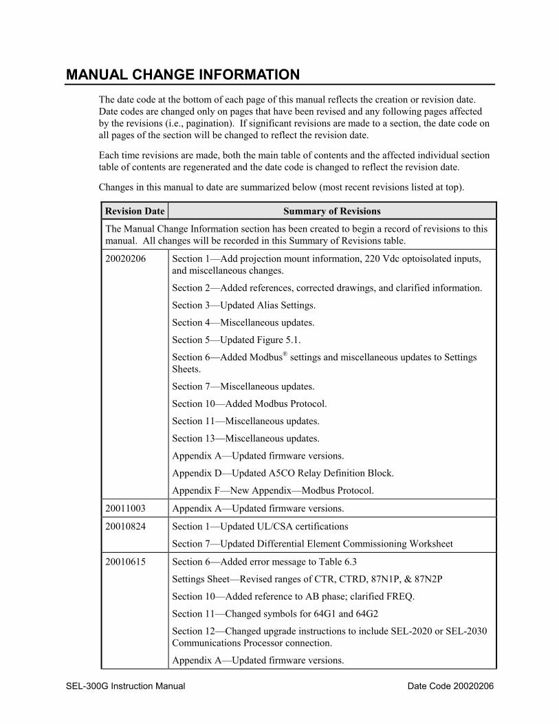
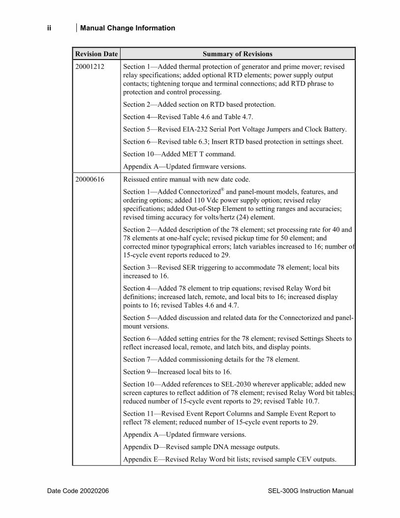
MANUAL CHANGE INFORMATION The date code at the bottom of each page of this manual reflects the creation or revision date. Date codes are changed only on pages that have been revised and any following pages affected by the revisions (i.e., pagination). If significant revisions are made to a section, the date code on all pages of the section will be changed to reflect the revision date.
Each time revisions are made, both the main table of contents and the affected individual section table of contents are regenerated and the date code is changed to reflect the revision date.
Changes in this manual to date are summarized below (most recent revisions listed at top).
Revision Date Summary of Revisions
The Manual Change Information section has been created to begin a record of revisions to this manual. All changes will be recorded in this Summary of Revisions table.
20020206 Section 1Add projection mount information, 220 Vdc optoisolated inputs, and miscellaneous changes.
Section 2Added references, corrected drawings, and clarified information.
Section 3Updated Alias Settings.
Section 4Miscellaneous updates.
Section 5Updated Figure 5.1.
Section 6Added Modbus® settings and miscellaneous updates to Settings Sheets.
Section 7Miscellaneous updates.
Section 10Added Modbus Protocol.
Section 11Miscellaneous updates.
Section 13Miscellaneous updates.
Appendix AUpdated firmware versions.
Appendix DUpdated A5CO Relay Definition Block.
Appendix FNew AppendixModbus Protocol.
20011003 Appendix AUpdated firmware versions.
20010824 Section 1Updated UL/CSA certifications
Section 7Updated Differential Element Commissioning Worksheet
20010615 Section 6Added error message to Table 6.3
Settings SheetRevised ranges of CTR, CTRD, 87N1P, & 87N2P
Section 10Added reference to AB phase; clarified FREQ.
Section 11Changed symbols for 64G1 and 64G2
Section 12Changed upgrade instructions to include SEL-2020 or SEL-2030 Communications Processor connection.
Appendix AUpdated firmware versions.
ii Manual Change Information
Date Code 20020206 SEL-300G Instruction Manual
Revision Date Summary of Revisions
20001212 Section 1Added thermal protection of generator and prime mover; revised relay specifications; added optional RTD elements; power supply output contacts; tightening torque and terminal connections; add RTD phrase to protection and control processing.
Section 2Added section on RTD based protection.
Section 4Revised Table 4.6 and Table 4.7.
Section 5Revised EIA-232 Serial Port Voltage Jumpers and Clock Battery.
Section 6Revised table 6.3; Insert RTD based protection in settings sheet.
Section 10Added MET T command.
Appendix AUpdated firmware versions.
20000616 Reissued entire manual with new date code.
Section 1Added Connectorized® and panel-mount models, features, and ordering options; added 110 Vdc power supply option; revised relay specifications; added Out-of-Step Element to setting ranges and accuracies; revised timing accuracy for volts/hertz (24) element.
Section 2Added description of the 78 element; set processing rate for 40 and 78 elements at one-half cycle; revised pickup time for 50 element; and corrected minor typographical errors; latch variables increased to 16; number of15-cycle event reports reduced to 29.
Section 3Revised SER triggering to accommodate 78 element; local bits increased to 16.
Section 4Added 78 element to trip equations; revised Relay Word bit definitions; increased latch, remote, and local bits to 16; increased display points to 16; revised Tables 4.6 and 4.7.
Section 5Added discussion and related data for the Connectorized and panel-mount versions.
Section 6Added setting entries for the 78 element; revised Settings Sheets to reflect increased local, remote, and latch bits, and display points.
Section 7Added commissioning details for the 78 element.
Section 9Increased local bits to 16.
Section 10Added references to SEL-2030 wherever applicable; added new screen captures to reflect addition of 78 element; revised Relay Word bit tables; reduced number of 15-cycle event reports to 29; revised Table 10.7.
Section 11Revised Event Report Columns and Sample Event Report to reflect 78 element; reduced number of 15-cycle event reports to 29.
Appendix AUpdated firmware versions.
Appendix DRevised sample DNA message outputs.
Appendix ERevised Relay Word bit lists; revised sample CEV outputs.
Manual Change Information iii
SEL-300G Instruction Manual Date Code 20020206
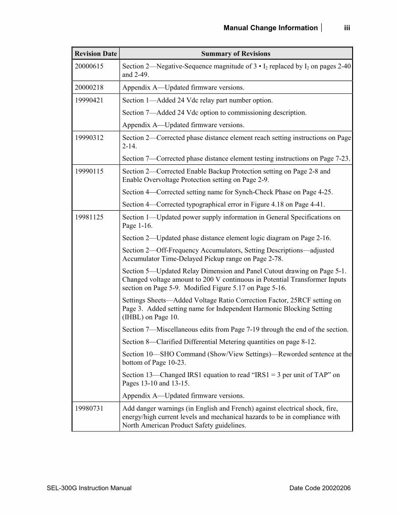
Revision Date Summary of Revisions
20000615 Section 2Negative-Sequence magnitude of 3 I2 replaced by I2 on pages 2-40 and 2-49.
20000218 Appendix AUpdated firmware versions.
19990421 Section 1Added 24 Vdc relay part number option.
Section 7Added 24 Vdc option to commissioning description.
Appendix AUpdated firmware versions.
19990312 Section 2Corrected phase distance element reach setting instructions on Page 2-14.
Section 7Corrected phase distance element testing instructions on Page 7-23.
19990115 Section 2Corrected Enable Backup Protection setting on Page 2-8 and Enable Overvoltage Protection setting on Page 2-9.
Section 4Corrected setting name for Synch-Check Phase on Page 4-25.
Section 4Corrected typographical error in Figure 4.18 on Page 4-41.
19981125 Section 1Updated power supply information in General Specifications on Page 1-16.
Section 2Updated phase distance element logic diagram on Page 2-16.
Section 2Off-Frequency Accumulators, Setting Descriptionsadjusted Accumulator Time-Delayed Pickup range on Page 2-78.
Section 5Updated Relay Dimension and Panel Cutout drawing on Page 5-1. Changed voltage amount to 200 V continuous in Potential Transformer Inputs section on Page 5-9. Modified Figure 5.17 on Page 5-16.
Settings SheetsAdded Voltage Ratio Correction Factor, 25RCF setting on Page 3. Added setting name for Independent Harmonic Blocking Setting (IHBL) on Page 10.
Section 7Miscellaneous edits from Page 7-19 through the end of the section.
Section 8Clarified Differential Metering quantities on page 8-12.
Section 10SHO Command (Show/View Settings)Reworded sentence at the bottom of Page 10-23.
Section 13Changed IRS1 equation to read IRS1 = 3 per unit of TAP on Pages 13-10 and 13-15.
Appendix AUpdated firmware versions.
19980731 Add danger warnings (in English and French) against electrical shock, fire, energy/high current levels and mechanical hazards to be in compliance with North American Product Safety guidelines.

iv Manual Change Information
Date Code 20020206 SEL-300G Instruction Manual
Revision Date Summary of Revisions
19980717 Create Relay Models 0300G2 and 0300G3, making synch-check option available. Add support for open-delta pts. Add 27PP2, 59PP2 phase-to-phase voltage elements. Add 21P phase mho distance elements, add EBUP setting to enable one backup protection element at a time. Add 87N ground differential element to models 0300G0 and 0300G2. Add single-phase 50H2 element settings to models 0300G1 and 0300G3. Reduce maximum voltage element setting to 200.0 V secondary Remove 51P phase time-overcurrent element. Add error message tables; add relay model tables to Section 1. Modify page format.
19980429 Modify Appendix A.
19980417 Correct typographical errors; Clarify relay setting precision.
19980320 Added Section 13: Differential Element Settings;
Added differential element test information and Differential Element Commissioning Worksheet to Section 7: Relay Commissioning;
Moved VNOM and INOM settings from Global to Group setting;
Added MET DIF and EVE DIF command descriptions;
Clarified the calculation of the 64G2P setting.
19980130 Initial Release.
SEL-300G Instruction Manual Date Code 20020206
TABLE OF CONTENTS
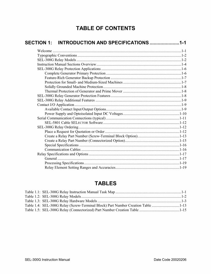
SECTION 1: INTRODUCTION AND SPECIFICATIONS ......................1-1
Welcome .......................................................................................................................................1-1 Typographic Conventions .............................................................................................................1-2 SEL-300G Relay Models ..............................................................................................................1-2 Instruction Manual Sections Overview.........................................................................................1-4 SEL-300G Relay Protection Applications ....................................................................................1-6
Complete Generator Primary Protection ...............................................................................1-6 Feature-Rich Generator Backup Protection ..........................................................................1-7 Protection for Small- and Medium-Sized Machines .............................................................1-7 Solidly Grounded Machine Protection..................................................................................1-8 Thermal Protection of Generator and Prime Mover .............................................................1-8
SEL-300G Relay Generator Protection Features ..........................................................................1-8 SEL-300G Relay Additional Features ..........................................................................................1-9 Contact I/O Application ................................................................................................................1-9
Available Contact Input/Output Options...............................................................................1-9 Power Supply and Optoisolated Input DC Voltages...........................................................1-10
Serial Communication Connections (typical) .............................................................................1-11 SEL-5801 Cable SELECTOR Software ................................................................................1-12
SEL-300G Relay Ordering..........................................................................................................1-12 Place a Request for Quotation or Order ..............................................................................1-12 Create a Relay Part Number (Screw-Terminal Block Option)............................................1-13 Create a Relay Part Number (Connectorized Option).........................................................1-15 Special Specifications .........................................................................................................1-16 Communication Cables .......................................................................................................1-16
Relay Specifications and Options ...............................................................................................1-17 General ................................................................................................................................1-17 Processing Specifications....................................................................................................1-19 Relay Element Setting Ranges and Accuracies...................................................................1-19
TABLES Table 1.1: SEL-300G Relay Instruction Manual Task Map .....................................................................1-1 Table 1.2: SEL-300G Relay Models .........................................................................................................1-2 Table 1.3: SEL-300G Relay Hardware Models ........................................................................................1-3 Table 1.4: SEL-300G Relay (Screw-Terminal Block) Part Number Creation Table .............................1-13 Table 1.5: SEL-300G Relay (Connectorized) Part Number Creation Table ..........................................1-15

ii Introduction and Specifications
Date Code 20020206 SEL-300G Instruction Manual
FIGURES Figure 1.1: Large Generator Primary and Backup Protection...................................................................1-6 Figure 1.2: Generator Differential Zone May Include Transformer .........................................................1-7 Figure 1.3: Simple Protection for Resistance Grounded Generators ........................................................1-7 Figure 1.4: Generator Thermal Protection with SEL-2600 & SEL-300G Relay ......................................1-8 Figure 1.5: SEL-300G Relay Communication Connection Examples....................................................1-11
Introduction and Specifications 1-1
SEL-300G Instruction Manual Date Code 20020206
SECTION 1: INTRODUCTION AND SPECIFICATIONS
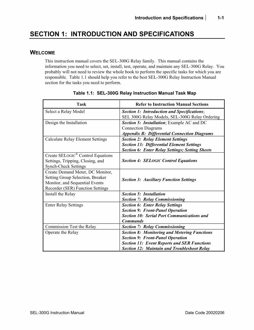
WELCOME This instruction manual covers the SEL-300G Relay family. This manual contains the information you need to select, set, install, test, operate, and maintain any SEL-300G Relay. You probably will not need to review the whole book to perform the specific tasks for which you are responsible. Table 1.1 should help you refer to the best SEL-300G Relay Instruction Manual section for the tasks you need to perform.
Table 1.1: SEL-300G Relay Instruction Manual Task Map
Task Refer to Instruction Manual Sections Select a Relay Model Section 1: Introduction and Specifications;
SEL 300G Relay Models, SEL-300G Relay Ordering Design the Installation Section 5: Installation; Example AC and DC
Connection Diagrams Appendix B: Differential Connection Diagrams
Calculate Relay Element Settings Section 2: Relay Element Settings Section 13: Differential Element Settings Section 6: Enter Relay Settings; Setting Sheets
Create SELOGIC® Control Equations Settings, Tripping, Closing, and Synch-Check Settings
Section 4: SELOGIC Control Equations
Create Demand Meter, DC Monitor, Setting Group Selection, Breaker Monitor, and Sequential Events Recorder (SER) Function Settings
Section 3: Auxiliary Function Settings
Install the Relay Section 5: Installation Section 7: Relay Commissioning
Enter Relay Settings Section 6: Enter Relay Settings Section 9: Front-Panel Operation Section 10: Serial Port Communications and Commands
Commission Test the Relay Section 7: Relay Commissioning Operate the Relay Section 8: Monitoring and Metering Functions
Section 9: Front-Panel Operation Section 11: Event Reports and SER Functions Section 12: Maintain and Troubleshoot Relay
1-2 Introduction and Specifications
Date Code 20020206 SEL-300G Instruction Manual
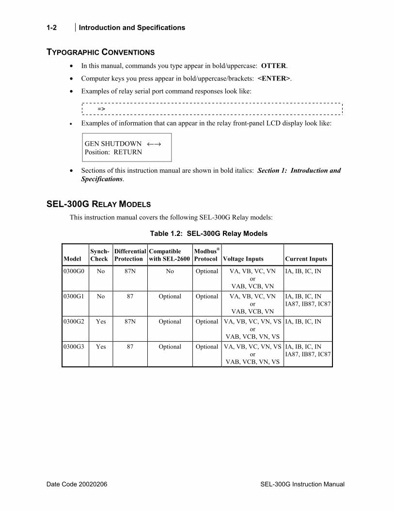
TYPOGRAPHIC CONVENTIONS • In this manual, commands you type appear in bold/uppercase: OTTER.
• Computer keys you press appear in bold/uppercase/brackets: <ENTER>.
• Examples of relay serial port command responses look like:
=>
• Examples of information that can appear in the relay front-panel LCD display look like:
GEN SHUTDOWN ←→ Position: RETURN
• Sections of this instruction manual are shown in bold italics: Section 1: Introduction and Specifications.
SEL-300G RELAY MODELS This instruction manual covers the following SEL-300G Relay models:
Table 1.2: SEL-300G Relay Models
Model Synch-Check
Differential Protection
Compatible with SEL-2600
Modbus® Protocol Voltage Inputs Current Inputs
0300G0 No 87N No Optional VA, VB, VC, VN or
VAB, VCB, VN
IA, IB, IC, IN
0300G1 No 87 Optional Optional VA, VB, VC, VN or
VAB, VCB, VN
IA, IB, IC, IN IA87, IB87, IC87
0300G2 Yes 87N Optional Optional VA, VB, VC, VN, VS or
VAB, VCB, VN, VS
IA, IB, IC, IN
0300G3 Yes 87 Optional Optional VA, VB, VC, VN, VS or
VAB, VCB, VN, VS
IA, IB, IC, IN IA87, IB87, IC87

Introduction and Specifications 1-3
SEL-300G Instruction Manual Date Code 20020206
Table 1.3: SEL-300G Relay Hardware Models
Model Mounting
Type Rack Unit
Height (I/O)*
Rear-Panel Connection
Type
Output Contact
Type Reference
Figures
0300G_0H Rack 2U 6/8 screw-terminal block
standard 5.1, 5.2, 5.45.7
0300G_03 Panel 2U 6/8 screw-terminal block
standard 5.1, 5.3, 5.45.7
0300G_1H Rack 3U 6/8 screw-terminal block
standard 5.1, 5.2, 5.45.7
8/12 screw-terminal block
standard or high current interrupting
0300G_13 Panel 3U 6/8 screw-terminal block
standard 5.1, 5.3, 5.45.7
8/12 screw-terminal block
standard or high current interrupting
0300G_WH Rack 2U 6/8 Connectorized® standard 5.1, 5.2, 5.85.11
0300G_W3 Panel 2U 6/8 Connectorized standard 5.1, 5.3, 5.85.11
0300G_YH Rack 3U 6/8 Connectorized standard 5.1, 5.2, 5.85.11
8/12 Connectorized standard or high current interrupting
0300G_Y3 Panel 3U 6/8 Connectorized standard 5.1, 5.3, 5.85.11
8/12 Connectorized standard or high current interrupting
* Number of Optoisolated Input/Output Contacts
The model numbers in Table 1.2 and Table 1.3 are only part of an actual ordering numberenough to distinguish one model type from another. They should not be used to order an SEL-300G Relay. Refer to SEL-300G Relay Ordering at the end of this section.
Throughout this instruction manual, when differences among the SEL-300G Relay models in Table 1.3 are explained, model numbers are referenced for clarity.
1-4 Introduction and Specifications
Date Code 20020206 SEL-300G Instruction Manual
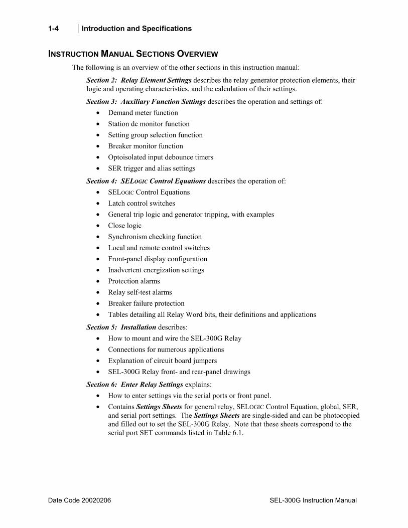
INSTRUCTION MANUAL SECTIONS OVERVIEW The following is an overview of the other sections in this instruction manual:
Section 2: Relay Element Settings describes the relay generator protection elements, their logic and operating characteristics, and the calculation of their settings.
Section 3: Auxiliary Function Settings describes the operation and settings of: • Demand meter function • Station dc monitor function • Setting group selection function • Breaker monitor function • Optoisolated input debounce timers • SER trigger and alias settings
Section 4: SELOGIC Control Equations describes the operation of: • SELOGIC Control Equations • Latch control switches • General trip logic and generator tripping, with examples • Close logic • Synchronism checking function • Local and remote control switches • Front-panel display configuration • Inadvertent energization settings • Protection alarms • Relay self-test alarms • Breaker failure protection • Tables detailing all Relay Word bits, their definitions and applications
Section 5: Installation describes: • How to mount and wire the SEL-300G Relay • Connections for numerous applications • Explanation of circuit board jumpers • SEL-300G Relay front- and rear-panel drawings
Section 6: Enter Relay Settings explains: • How to enter settings via the serial ports or front panel. • Contains Settings Sheets for general relay, SELOGIC Control Equation, global, SER,
and serial port settings. The Settings Sheets are single-sided and can be photocopied and filled out to set the SEL-300G Relay. Note that these sheets correspond to the serial port SET commands listed in Table 6.1.

Introduction and Specifications 1-5
SEL-300G Instruction Manual Date Code 20020206
Section 7: Relay Commissioning describes: • Commissioning test philosophy and detailed procedure • Detailed protection element test procedures
Section 8: Monitoring and Metering Functions describes the operation of: • Generator operating statistics function • Breaker monitor • Station dc battery monitor function • Energy and maximum/minimum metering
Section 9: Front-Panel Operation explains how to enter settings and also contains the following setting reference information:
• Front-panel target LEDs • Front-panel pushbuttons and correspondence to serial port commands • Local control switches (local bit outputs LB1 through LB8) • Rotating default displays
Section 10: Serial Port Communications and Commands describes: • Serial port connector pinout/terminal functions • Communications cables • Communications protocol • Serial port commands
Section 11: Event Reports and SER Functions describes: • Standard 15- and 30-cycle event reports • Sequential Events Recorder (SER) report • Synchronism checking reports
Section 12: Maintain and Troubleshoot Relay describes: • Relay maintenance testing philosophy • Relay troubleshooting • Firmware upgrade instructions
Section 13: Differential Element Settings describes: • Generator differential protection elements • Logic and operating characteristics • Settings calculation
Appendices contains the following appendices: • Appendix A: Firmware Versions • Appendix B: Differential Connection Diagrams • Appendix C: SEL Distributed Port Switch Protocol • Appendix D: Configuration, Fast Meter, and Fast Operate Commands • Appendix E: Compressed ASCII Commands • Appendix F: Modbus® RTU Communications Protocol
1-6 Introduction and Specifications
Date Code 20020206 SEL-300G Instruction Manual
SEL-300G Relay Command Summary briefly describes the serial port commands that are described in detail in Section 10: Serial Port Communications and Commands.
SEL-300G RELAY PROTECTION APPLICATIONS
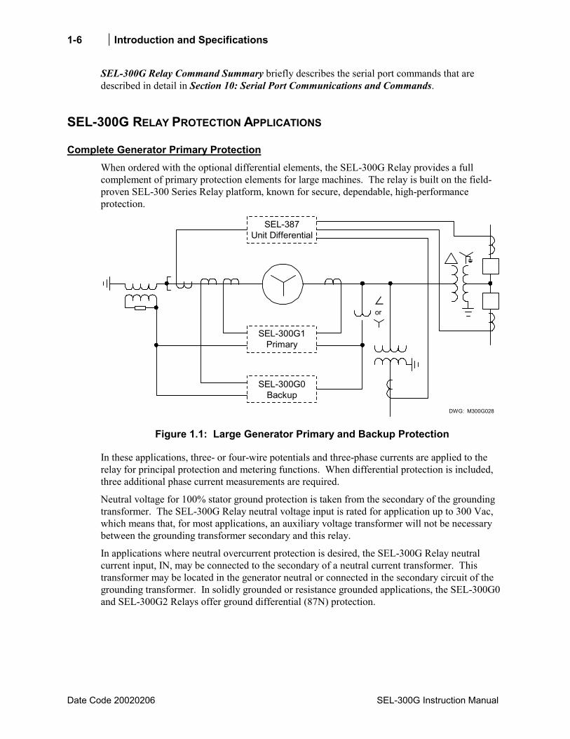
Complete Generator Primary Protection When ordered with the optional differential elements, the SEL-300G Relay provides a full complement of primary protection elements for large machines. The relay is built on the field- proven SEL-300 Series Relay platform, known for secure, dependable, high-performance protection.
DWG: M300G028
SEL-387Unit Differential
SEL-300G1Primary
SEL-300G0Backup
or
Figure 1.1: Large Generator Primary and Backup Protection
In these applications, three- or four-wire potentials and three-phase currents are applied to the relay for principal protection and metering functions. When differential protection is included, three additional phase current measurements are required.
Neutral voltage for 100% stator ground protection is taken from the secondary of the grounding transformer. The SEL-300G Relay neutral voltage input is rated for application up to 300 Vac, which means that, for most applications, an auxiliary voltage transformer will not be necessary between the grounding transformer secondary and this relay.
In applications where neutral overcurrent protection is desired, the SEL-300G Relay neutral current input, IN, may be connected to the secondary of a neutral current transformer. This transformer may be located in the generator neutral or connected in the secondary circuit of the grounding transformer. In solidly grounded or resistance grounded applications, the SEL-300G0 and SEL-300G2 Relays offer ground differential (87N) protection.
Introduction and Specifications 1-7
SEL-300G Instruction Manual Date Code 20020206
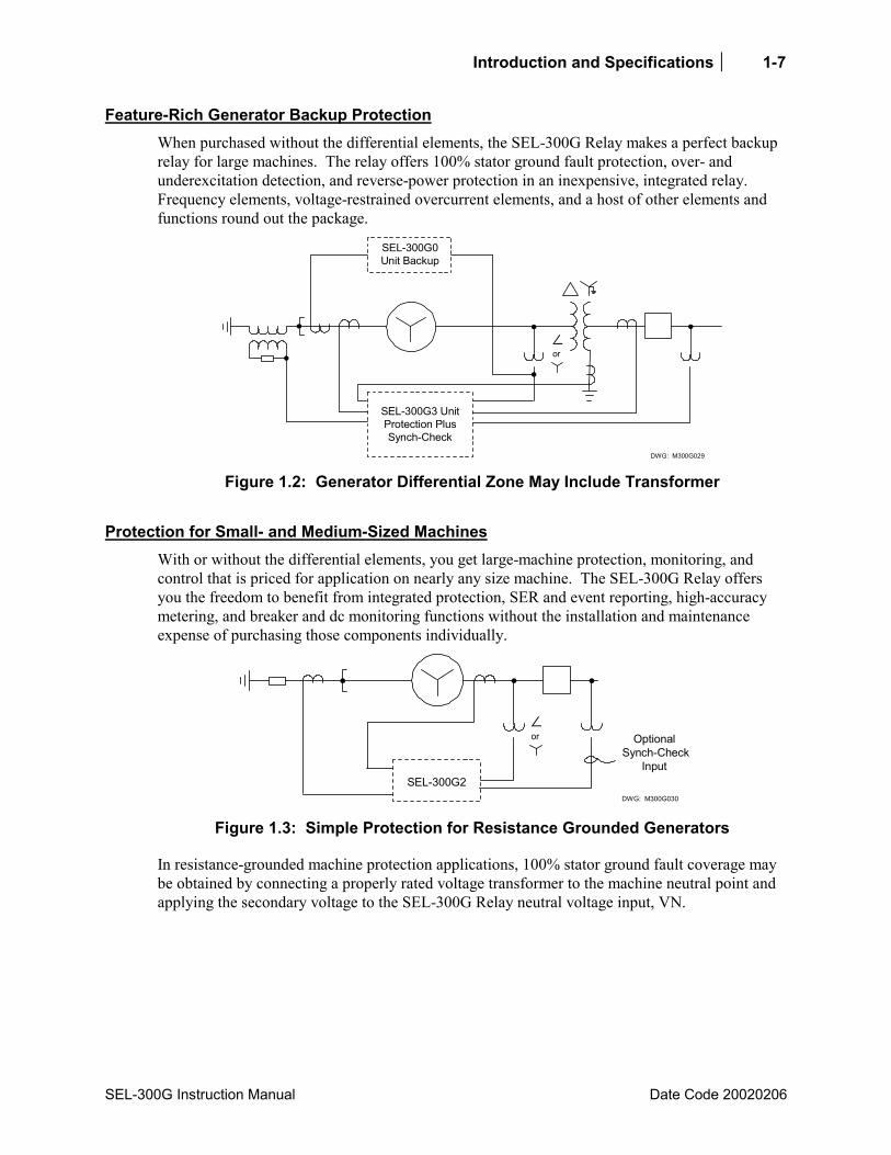
Feature-Rich Generator Backup Protection When purchased without the differential elements, the SEL-300G Relay makes a perfect backup relay for large machines. The relay offers 100% stator ground fault protection, over- and underexcitation detection, and reverse-power protection in an inexpensive, integrated relay. Frequency elements, voltage-restrained overcurrent elements, and a host of other elements and functions round out the package.
DWG: M300G029
SEL-300G0Unit Backup
SEL-300G3 UnitProtection PlusSynch-Check
or
Figure 1.2: Generator Differential Zone May Include Transformer
Protection for Small- and Medium-Sized Machines With or without the differential elements, you get large-machine protection, monitoring, and control that is priced for application on nearly any size machine. The SEL-300G Relay offers you the freedom to benefit from integrated protection, SER and event reporting, high-accuracy metering, and breaker and dc monitoring functions without the installation and maintenance expense of purchasing those components individually.
DWG: M300G030
SEL-300G2
Optional Synch-Check
Input
or
Figure 1.3: Simple Protection for Resistance Grounded Generators
In resistance-grounded machine protection applications, 100% stator ground fault coverage may be obtained by connecting a properly rated voltage transformer to the machine neutral point and applying the secondary voltage to the SEL-300G Relay neutral voltage input, VN.

1-8 Introduction and Specifications
Date Code 20020206 SEL-300G Instruction Manual
Solidly Grounded Machine Protection The SEL-300G Relay is suitable to protect solidly grounded machines, with the exception that the relay does not provide 100% stator ground fault protection for these machines. Phase, negative-sequence, and neutral overcurrent fault detection methods, plus optional differential overcurrent protection, are provided. Abnormal operating condition protection, such as loss-of-field, antimotoring, and overexcitation protection, is also provided.
Thermal Protection of Generator and Prime Mover
The SEL-300G Relay models compatible with SEL-2600 RTD Module (refer to Table 1.2 for Model Number detail) provide Thermal Protection for the Generator and Prime Mover. The RTD types and locations are individually configurable. Either ambient temperature or generator load current can be configured to bias the winding RTD trip temperature thresholds.
SEL-2600 SEL-300GRelay
Generator PrimeMover
Fiber-Optic Port
(built into SEL-2600) (SEL-2800 plugged onto any DB-9 connector)
Up to 500 meters viasingle fiber-opticcable, SEL partnumber C801FD
Up to 12 RTD inputs,plus one contact
DWG: M300G253
Figure 1.4: Generator Thermal Protection with SEL-2600 & SEL-300G Relay
SEL-300G RELAY GENERATOR PROTECTION FEATURES The SEL-300G Relay offers a full range of elements for generator protection, such as: • Optional Percentage Restrained Differential Protection (included in SEL-0300G1 and
SEL-0300G3 models) • Optional 87N Ground Differential Protection (included in SEL-0300G0 and SEL-0300G2
models) • 100 Percent Stator Ground Detection (for high-impedance and resistance grounded
generators) • Reverse/Low-Forward Power Elements • Volts/Hertz Elements for Overexcitation Protection • Loss-of-Field Protection • Negative-Sequence Overcurrent Protection • Voltage-Restrained Phase Time-Overcurrent Elements • Voltage-Controlled Phase Time-Overcurrent Elements • Backup Phase Distance Elements • Neutral Overcurrent Elements • Under- and Overvoltage Elements for Protection and Control • Loss-of-Potential Logic

Introduction and Specifications 1-9
SEL-300G Instruction Manual Date Code 20020206
• Optional Synchronism Checking (included in SEL-0300G2 and SEL-0300G3 models) • Flexible Inadvertent Energization Detection • Secure Under- and Overfrequency Protection, Plus Off-Fundamental Time Accumulators per
IEEE C37.106 : 1987 • Breaker Failure Protection • Out-of-Step Protection (single and double blinder schemes) • Thermal Protection (included in models compatible with SEL-2600 RTD Module).
SEL-300G RELAY ADDITIONAL FEATURES In addition to the protection functions outlined above, the SEL-300G Relay offers advanced measuring and monitoring capabilities not found on other generator relays. • Extensive High-Accuracy Metering Capabilities • Configurable Front-Panel Display Replaces Separate Panel Meters • Event Report and SER Reporting • Advanced SELOGIC Control Equations • Contact Inputs and Outputs • Breaker Monitor • Station Battery Monitor • Two Independent Setting Groups
CONTACT I/O APPLICATION
Available Contact Input/Output Options The SEL-300G Relay is available in several hardware configurations. These configurations are differentiated by the following: • Chassis size (2U or 3U) • Mounting type (panel or rack) • Type of connections at the rear (Screw-Terminal Block or Connectorized®) • Number of optoisolated inputs • Number of contact outputs
Relay Models SEL-0300G_0H, SEL-0300G_03, SEL-0300G_WH, and SEL-0300G_W3 The relays listed above provide seven programmable output contacts, plus a self-test ALARM contact and six optoisolated inputs in a two-rack unit package. All output contacts are rated to make and carry trip coil current per the requirements of IEEE C37.90 : 1989. These contacts are not rated to interrupt trip coil current.
Relay Models SEL-0300G_1H, SEL-0300G_13, SEL-0300G_YH, and SEL-0300G_Y3 The relays listed above provide 19 programmable output contacts, plus a self-test ALARM contact and 14 optoisolated inputs in a three-rack unit package. All output contacts are rated to make and carry trip coil current per the requirements of IEEE C37.90 : 1989. Seven of the
1-10 Introduction and Specifications
Date Code 20020206 SEL-300G Instruction Manual
output contacts are not rated to interrupt trip coil current. Twelve of the output contacts may be purchased with high current interruption output contacts for applications requiring up to 10 A inductive interrupt capability.
Note: High current interrupting output contacts are polarity sensitive. Observe polarity markings by connecting even-number screw terminals to the higher voltage potential in the circuit. Do not use high current interrupting output contacts to switch ac control signals.
High Current Interrupting Output Contacts SEL-300G Relay purchased with the additional I/O board may be further specified to include high current interrupting output contacts. These contacts use an integrated-gate bipolar junction transistor to interrupt contact current in a controlled manner. This increases the contact interrupt rating, prevents contact arcing, and prevents the inductive voltage spike which occurs when an inductive current is interrupted by a standard contact.
Refer to the High current interruption option on page 1-17 for detailed specifications of the high current interrupting output contacts.
Note: High current interrupting output contacts are polarity sensitive. Observe polarity markings by connecting even-number screw terminals to the higher voltage potential in the circuit. Do not use high current interrupting output contacts to switch ac control signals.
Power Supply and Optoisolated Input DC Voltages The SEL-300G Relay is available in power supply configurations 125/250 V, 48/125 V, or 24/48 V.
Optoisolated inputs are available with the voltage ratings of 250, 220, 125, 110, 48, or 24 Vdc.
Both the power supply and the optoisolated input voltage ratings are selected when the relay is ordered. Refer to the Optoisolated Inputs on page 1-18 for detailed specifications.

Introduction and Specifications 1-11
SEL-300G Instruction Manual Date Code 20020206
SERIAL COMMUNICATION CONNECTIONS (TYPICAL)
Front Panel
SEL-2020
Rear PanelSEL-300G Relay (#2)
Front Panel
Rear PanelSEL-300G Relay (#1)
Front Panel
SEL-300G Relay(#1)
Computer
PORT 2
(METALLIC)Cable #C273A
SEL-300GRelay
SEL-300GRelay SEL-300G
Relay
SEL-2020Communications
Processor
SEL-300G Relay(#2)
SEL-300G Relay(#32)
DATA AND TIME-SYNCHRONIZATION CONNECTIONS
SEL-2020Communications
Processor
PORT 2
Fiber-Optic Cable#C273AFZ
or #C273AF0 SEL-2810
Optical Cable ConnectionMetallic Cable Connection
EIA-485 CONNECTIONS
PORT 1 PORT 1 PORT 1
LOCAL CONNECTIONS
CONNECT TO THE SEL-2020ONCE AND COMMUNICATE WITHANY CONNECTED SEL RELAY
PORT 2PORT 2
PORT FPORT F
OR . . .CONNECT TO THE SEL-300GRELAYS INDIVIDUALLY VIA THEFRONT-PANEL SERIAL PORT
DWG: M300G031 Figure 1.5: SEL-300G Relay Communication Connection Examples
1-12 Introduction and Specifications
Date Code 20020206 SEL-300G Instruction Manual
SEL-5801 Cable SELECTOR Software While you can view or modify many relay settings using the front-panel LCD interface, SELOGIC Control Equations to control relay contact outputs must be entered via a relay serial port using a PC, terminal emulation software, and appropriate communication cable. The relay also supports communication with other local devices such as modems, port switches, and the SEL-2020/2030.
Communication with these external devices requires appropriate cable. Some of the most common cables are called out in Figure 1.5. Use the SEL-5801 Cable SELECTOR Software, available free of charge from SEL, to determine the SEL cable part number to connect with other specific devices. You can purchase cables from SEL or refer to the cable pinout provided by the software and build your own.
To obtain your copy of SEL-5801 Cable SELECTOR Software, contact your SEL Representative, or download it directly from our World Wide Web site at http://www.selinc.com.
SEL-300G RELAY ORDERING To obtain a quotation or place an order for an SEL-300G Relay, it is helpful to have a relay part number. The information below will help you create a part number for the SEL-300G Relay and describe some additional information that you may wish to include when you place your relay order.
Place a Request for Quotation or Order You can order an SEL-300G Relay from your local SEL Sales Representative or Distributor Office, SEL Regional Technical Service Center, or directly from the factory. Contact us at the factory by telephone at (509) 332-1890 or by fax at (509) 334-7848.
Introduction and Specifications 1-13
SEL-300G Instruction Manual Date Code 20020206
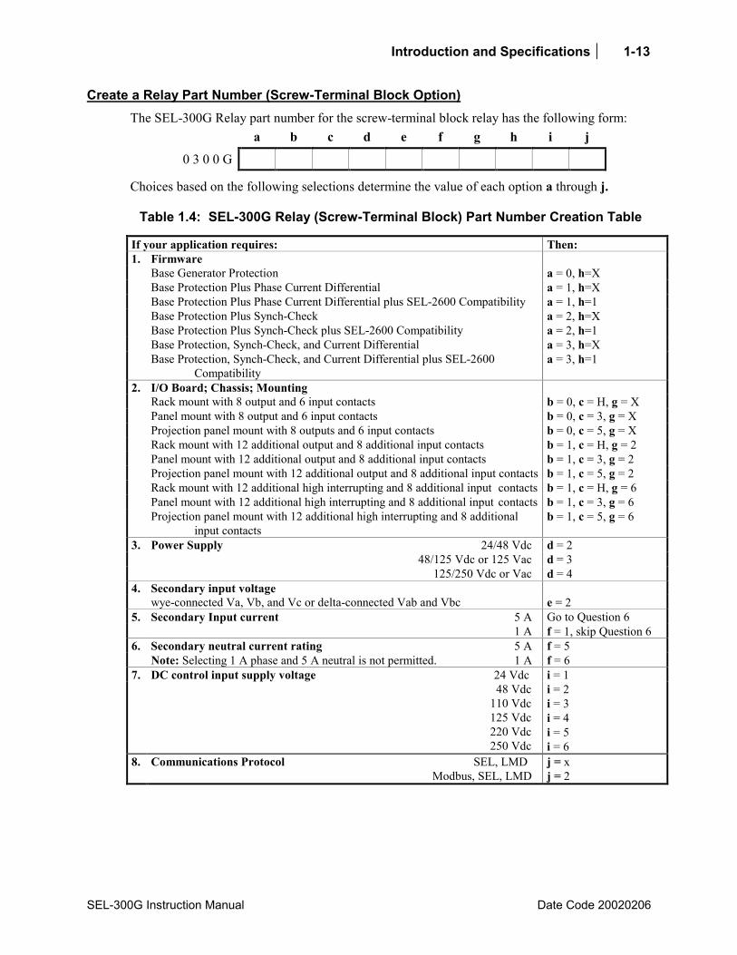
Create a Relay Part Number (Screw-Terminal Block Option) The SEL-300G Relay part number for the screw-terminal block relay has the following form:
a b c d e f g h i j
0 3 0 0 G
Choices based on the following selections determine the value of each option a through j.
Table 1.4: SEL-300G Relay (Screw-Terminal Block) Part Number Creation Table
If your application requires: Then: 1. Firmware Base Generator Protection a = 0, h=X Base Protection Plus Phase Current Differential a = 1, h=X Base Protection Plus Phase Current Differential plus SEL-2600 Compatibility a = 1, h=1 Base Protection Plus Synch-Check a = 2, h=X Base Protection Plus Synch-Check plus SEL-2600 Compatibility a = 2, h=1 Base Protection, Synch-Check, and Current Differential a = 3, h=X Base Protection, Synch-Check, and Current Differential plus SEL-2600
Compatibility a = 3, h=1
2. I/O Board; Chassis; Mounting Rack mount with 8 output and 6 input contacts b = 0, c = H, g = X Panel mount with 8 output and 6 input contacts b = 0, c = 3, g = X Projection panel mount with 8 outputs and 6 input contacts b = 0, c = 5, g = X Rack mount with 12 additional output and 8 additional input contacts b = 1, c = H, g = 2 Panel mount with 12 additional output and 8 additional input contacts b = 1, c = 3, g = 2 Projection panel mount with 12 additional output and 8 additional input contacts b = 1, c = 5, g = 2 Rack mount with 12 additional high interrupting and 8 additional input contacts b = 1, c = H, g = 6 Panel mount with 12 additional high interrupting and 8 additional input contacts b = 1, c = 3, g = 6 Projection panel mount with 12 additional high interrupting and 8 additional
input contacts b = 1, c = 5, g = 6
3. Power Supply 24/48 Vdc d = 2 48/125 Vdc or 125 Vac d = 3 125/250 Vdc or Vac d = 4 4. Secondary input voltage wye-connected Va, Vb, and Vc or delta-connected Vab and Vbc e = 2 5. Secondary Input current 5 A Go to Question 6 1 A f = 1, skip Question 6 6. Secondary neutral current rating 5 A f = 5 Note: Selecting 1 A phase and 5 A neutral is not permitted. 1 A f = 6 7. DC control input supply voltage 24 Vdc i = 1 48 Vdc
110 Vdc 125 Vdc 220 Vdc 250 Vdc
i = 2 i = 3 i = 4 i = 5 i = 6
8. Communications Protocol SEL, LMD Modbus, SEL, LMD
j = x j = 2
1-14 Introduction and Specifications
Date Code 20020206 SEL-300G Instruction Manual
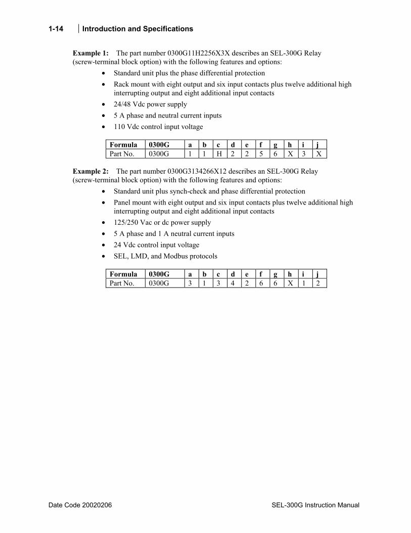
Example 1: The part number 0300G11H2256X3X describes an SEL-300G Relay (screw-terminal block option) with the following features and options:
• Standard unit plus the phase differential protection • Rack mount with eight output and six input contacts plus twelve additional high
interrupting output and eight additional input contacts • 24/48 Vdc power supply • 5 A phase and neutral current inputs • 110 Vdc control input voltage
Formula 0300G a b c d e f g h i j Part No. 0300G 1 1 H 2 2 5 6 X 3 X
Example 2: The part number 0300G3134266X12 describes an SEL-300G Relay (screw-terminal block option) with the following features and options:
• Standard unit plus synch-check and phase differential protection • Panel mount with eight output and six input contacts plus twelve additional high
interrupting output and eight additional input contacts • 125/250 Vac or dc power supply • 5 A phase and 1 A neutral current inputs • 24 Vdc control input voltage • SEL, LMD, and Modbus protocols
Formula 0300G a b c d e f g h i j Part No. 0300G 3 1 3 4 2 6 6 X 1 2
Introduction and Specifications 1-15
SEL-300G Instruction Manual Date Code 20020206
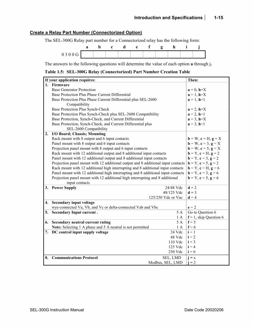
Create a Relay Part Number (Connectorized Option) The SEL-300G Relay part number for a Connectorized relay has the following form:
a b c d e f g h i j
0 3 0 0 G
The answers to the following questions will determine the value of each option a through j.
Table 1.5: SEL-300G Relay (Connectorized) Part Number Creation Table
If your application requires: Then: 1. Firmware Base Generator Protection a = 0, h=X Base Protection Plus Phase Current Differential a = 1, h=X Base Protection Plus Phase Current Differential plus SEL-2600
Compatibility a = 1, h=1
Base Protection Plus Synch-Check a = 2, h=X Base Protection Plus Synch-Check plus SEL-2600 Compatibility a = 2, h=1 Base Protection, Synch-Check, and Current Differential a = 3, h=X Base Protection, Synch-Check, and Current Differential plus
SEL-2600 Compatibility a = 3, h=1
2. I/O Board; Chassis; Mounting Rack mount with 8 output and 6 input contacts b = W, c = H, g = X Panel mount with 8 output and 6 input contacts b = W, c = 3, g = X Projection panel mount with 8 output and 6 input contacts b = W, c = 5, g = X Rack mount with 12 additional output and 8 additional input contacts b = Y, c = H, g = 2 Panel mount with 12 additional output and 8 additional input contacts b = Y, c = 3, g = 2 Projection panel mount with 12 additional output and 8 additional input contacts b = Y, c = 5, g = 2 Rack mount with 12 additional high interrupting and 8 additional input contacts b = Y, c = H, g = 6 Panel mount with 12 additional high interrupting and 8 additional input contacts b = Y, c = 3, g = 6 Projection panel mount with 12 additional high interrupting and 8 additional
input contacts b = Y, c = 5, g = 6
3. Power Supply 24/48 Vdc d = 2 48/125 Vdc d = 3 125/250 Vdc or Vac d = 4 4. Secondary input voltage wye-connected Va, Vb, and Vc or delta-connected Vab and Vbc e = 2 5. Secondary Input current . 5 A Go to Question 6 1 A f = 1, skip Question 6 6. Secondary neutral current rating 5 A f = 5 Note: Selecting 1 A phase and 5 A neutral is not permitted 1 A f = 6
DC control input supply voltage 24 Vdc 7. 48 Vdc
110 Vdc 125 Vdc 250 Vdc
i = 1 i = 2 i = 3 i = 4 i = 6
8. Communications Protocol SEL, LMD Modbus, SEL, LMD
j = x j = 2
1-16 Introduction and Specifications
Date Code 20020206 SEL-300G Instruction Manual
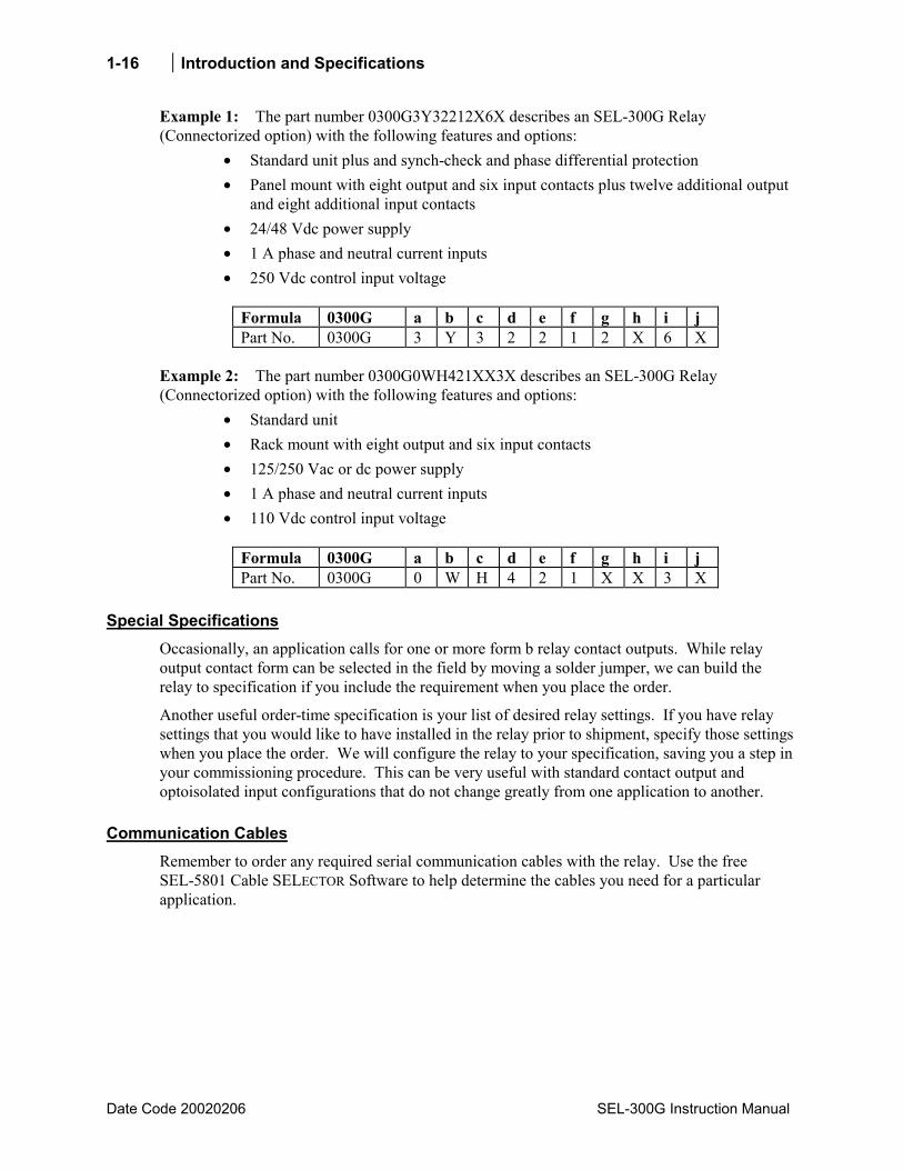
Example 1: The part number 0300G3Y32212X6X describes an SEL-300G Relay (Connectorized option) with the following features and options:
• Standard unit plus and synch-check and phase differential protection • Panel mount with eight output and six input contacts plus twelve additional output
and eight additional input contacts • 24/48 Vdc power supply • 1 A phase and neutral current inputs • 250 Vdc control input voltage
Formula 0300G a b c d e f g h i j Part No. 0300G 3 Y 3 2 2 1 2 X 6 X
Example 2: The part number 0300G0WH421XX3X describes an SEL-300G Relay (Connectorized option) with the following features and options:
• Standard unit • Rack mount with eight output and six input contacts • 125/250 Vac or dc power supply • 1 A phase and neutral current inputs • 110 Vdc control input voltage
Formula 0300G a b c d e f g h i j Part No. 0300G 0 W H 4 2 1 X X 3 X
Special Specifications Occasionally, an application calls for one or more form b relay contact outputs. While relay output contact form can be selected in the field by moving a solder jumper, we can build the relay to specification if you include the requirement when you place the order.
Another useful order-time specification is your list of desired relay settings. If you have relay settings that you would like to have installed in the relay prior to shipment, specify those settings when you place the order. We will configure the relay to your specification, saving you a step in your commissioning procedure. This can be very useful with standard contact output and optoisolated input configurations that do not change greatly from one application to another.
Communication Cables Remember to order any required serial communication cables with the relay. Use the free SEL-5801 Cable SELECTOR Software to help determine the cables you need for a particular application.

Introduction and Specifications 1-17
SEL-300G Instruction Manual Date Code 20020206
RELAY SPECIFICATIONS AND OPTIONS General Terminal Connections: Tightening Torque Terminal Block: Minimum: 8 in-lb (0.9 Nm) Maximum: 12 in-lb (1.4 Nm) Connectorized®: Minimum: 4.4 in-lb (0.5 Nm) Maximum: 8.8 in-lb (1.0 Nm) Terminals or stranded copper wire. Ring terminals are recommended. Minimum temperature rating of 105°C.
AC Current Inputs: 5 A Nominal 15 A continuous, linear to 100 A symmetrical. 500 A for 1 second. 1250 A for 1 cycle. Burden: 0.27 VA @ 5 A 2.51 VA @ 15 A 1 A Nominal 3 A continuous, linear to 20 A symmetrical 100 A for 1 second. 250 A for 1 cycle. Burden: 0.13 VA @ 1 A 1.31 VA @ 3 A
AC Voltage Inputs: 80140 VL-L Note: This is for effective use of Volts/Hertz (24) and Sensitive Directional Power (32) elements. 150 VL-N continuous limit for three-phase, four-wire wye-connection. 150 VL-L continuous limit for three-phase, three-wire delta-connection. 365 Vac for 10 seconds. 300 V continuous, VNNN neutral voltage input. 150 V continuous, VSNS synch voltage input. Burden: 0.13 VA @ 67 V 0.45 VA @ 120 V 0.80 VA @ 300 V
Power Supply: 125/250 Vdc or Vac Range: 85350 Vdc or 85264 Vac Burden: <25 W 48/125 Vdc or 125 Vac Range: 38200 Vdc or 85140 Vac Burden: <25 W 24/48 Vdc Range: 1860 Vdc polarity dependent Burden: <25 W
Output Contacts: Standard Make: 30 A Carry: 6 A @ 70°C
4 A @ 85°C
1 s Rating: 50 A MOV: 270 Vac, 360 Vdc, 40 J Pickup Time: <5 ms Breaking Capacity (10,000 operations): 24 V 0.75 A L/R = 40 ms 48 V 0.50 A L/R = 40 ms 125 V 0.30 A L/R = 40 ms 250 V 0.20 A L/R = 40 ms Cyclic Capacity (2.5 cycles/second): 24 V 0.75 A L/R = 40 ms 48 V 0.50 A L/R = 40 ms 125 V 0.30 A L/R = 40 ms 250 V 0.20 A L/R = 40 ms High current interruption option: Make: 30 A Carry: 6 A @ 70°C
4 A @ 85°C
MOV: 330 Vdc, 40 J Pickup time: <5 ms Dropout time: <8 ms Breaking Capacity (10,000 operations): 24 V 10 A L/R = 40 ms 48 V 10 A L/R = 40 ms 125 V 10 A L/R = 40 ms 250 V 10 A L/R = 20 ms Cyclic Capacity (4 cycles in 1 second, followed by 2 minutes idle for thermal dissipation): 24 V 10 A L/R = 40 ms 48 V 10 A L/R = 40 ms 125 V 10 A L/R = 40 ms 250 V 10 A L/R = 20 ms Note: Do not use high current interrupting output contacts to switch ac control signals. These outputs are polarity dependent. Note: Make per IEEE C37.90: 1989; Breaking and Cyclic Capacity per IEC 60255-23: 1994.
1-18 Introduction and Specifications
Date Code 20020206 SEL-300G Instruction Manual
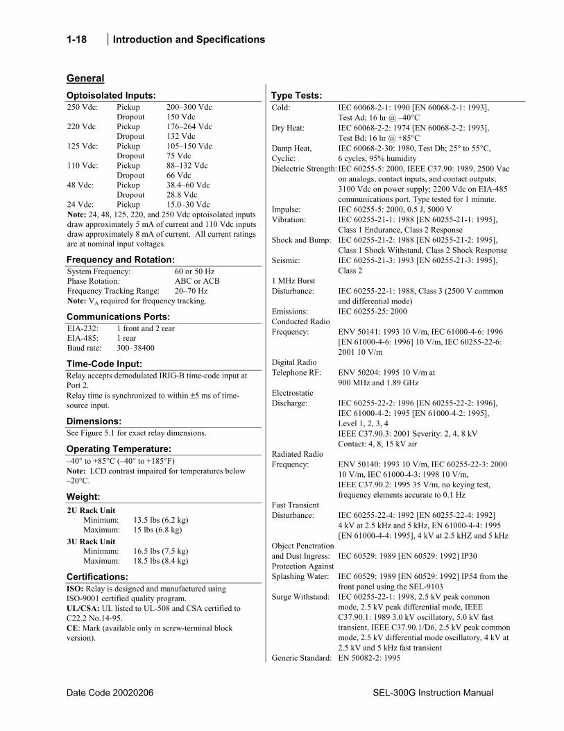
General Optoisolated Inputs: 250 Vdc: Pickup 200300 Vdc Dropout 150 Vdc 220 Vdc Pickup 176264 Vdc Dropout 132 Vdc 125 Vdc: Pickup 105150 Vdc Dropout 75 Vdc 110 Vdc: Pickup 88132 Vdc Dropout 66 Vdc 48 Vdc: Pickup 38.460 Vdc Dropout 28.8 Vdc 24 Vdc: Pickup 15.030 Vdc Note: 24, 48, 125, 220, and 250 Vdc optoisolated inputs draw approximately 5 mA of current and 110 Vdc inputs draw approximately 8 mA of current. All current ratings are at nominal input voltages.
Frequency and Rotation: System Frequency: 60 or 50 Hz Phase Rotation: ABC or ACB Frequency Tracking Range: 2070 Hz Note: VA required for frequency tracking.
Communications Ports: EIA-232: 1 front and 2 rear EIA-485: 1 rear Baud rate: 30038400
Time-Code Input: Relay accepts demodulated IRIG-B time-code input at Port 2. Relay time is synchronized to within ±5 ms of time-source input.
Dimensions: See Figure 5.1 for exact relay dimensions.
Operating Temperature: 40° to +85°C (40° to +185°F) Note: LCD contrast impaired for temperatures below 20°C.
Weight: 2U Rack Unit Minimum: 13.5 lbs (6.2 kg) Maximum: 15 lbs (6.8 kg) 3U Rack Unit Minimum: 16.5 lbs (7.5 kg) Maximum: 18.5 lbs (8.4 kg)
Certifications: ISO: Relay is designed and manufactured using ISO-9001 certified quality program. UL/CSA: UL listed to UL-508 and CSA certified to C22.2 No.14-95. CE: Mark (available only in screw-terminal block version).
Type Tests: Cold: IEC 60068-2-1: 1990 [EN 60068-2-1: 1993],
Test Ad; 16 hr @ 40°C Dry Heat: IEC 60068-2-2: 1974 [EN 60068-2-2: 1993],
Test Bd; 16 hr @ +85°C Damp Heat, Cyclic:
IEC 60068-2-30: 1980, Test Db; 25° to 55°C, 6 cycles, 95% humidity
Dielectric Strength: IEC 60255-5: 2000, IEEE C37.90: 1989, 2500 Vac on analogs, contact inputs, and contact outputs; 3100 Vdc on power supply; 2200 Vdc on EIA-485 communications port. Type tested for 1 minute.
Impulse: IEC 60255-5: 2000, 0.5 J, 5000 V Vibration: IEC 60255-21-1: 1988 [EN 60255-21-1: 1995],
Class 1 Endurance, Class 2 Response Shock and Bump: IEC 60255-21-2: 1988 [EN 60255-21-2: 1995],
Class 1 Shock Withstand, Class 2 Shock ResponseSeismic: IEC 60255-21-3: 1993 [EN 60255-21-3: 1995],
Class 2 1 MHz Burst Disturbance:
IEC 60255-22-1: 1988, Class 3 (2500 V common and differential mode)
Emissions: IEC 60255-25: 2000 Conducted Radio Frequency:
ENV 50141: 1993 10 V/m, IEC 61000-4-6: 1996 [EN 61000-4-6: 1996] 10 V/m, IEC 60255-22-6: 2001 10 V/m
Digital Radio Telephone RF:
ENV 50204: 1995 10 V/m at 900 MHz and 1.89 GHz
Electrostatic Discharge:
IEC 60255-22-2: 1996 [EN 60255-22-2: 1996], IEC 61000-4-2: 1995 [EN 61000-4-2: 1995], Level 1, 2, 3, 4 IEEE C37.90.3: 2001 Severity: 2, 4, 8 kV Contact: 4, 8, 15 kV air
Radiated Radio Frequency:
ENV 50140: 1993 10 V/m, IEC 60255-22-3: 2000 10 V/m, IEC 61000-4-3: 1998 10 V/m, IEEE C37.90.2: 1995 35 V/m, no keying test, frequency elements accurate to 0.1 Hz
Fast Transient Disturbance:
IEC 60255-22-4: 1992 [EN 60255-22-4: 1992] 4 kV at 2.5 kHz and 5 kHz, EN 61000-4-4: 1995 [EN 61000-4-4: 1995], 4 kV at 2.5 kHZ and 5 kHz
Object Penetration and Dust Ingress:
IEC 60529: 1989 [EN 60529: 1992] IP30
Protection Against Splashing Water:
IEC 60529: 1989 [EN 60529: 1992] IP54 from the front panel using the SEL-9103
Surge Withstand: IEC 60255-22-1: 1998, 2.5 kV peak common mode, 2.5 kV peak differential mode, IEEE C37.90.1: 1989 3.0 kV oscillatory, 5.0 kV fast transient, IEEE C37.90.1/D6, 2.5 kV peak common mode, 2.5 kV differential mode oscillatory, 4 kV at 2.5 kV and 5 kHz fast transient
Generic Standard: EN 50082-2: 1995
Introduction and Specifications 1-19
SEL-300G Instruction Manual Date Code 20020206
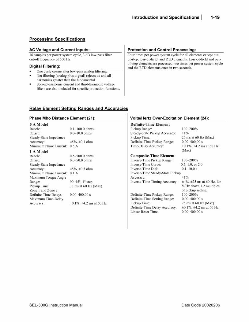
Processing Specifications
AC Voltage and Current Inputs: 16 samples per power system cycle, 3 dB low-pass filter cut-off frequency of 560 Hz.
Digital Filtering: One cycle cosine after low-pass analog filtering. Net filtering (analog plus digital) rejects dc and all
harmonics greater than the fundamental. Second-harmonic current and third-harmonic voltage
filters are also included for specific protection functions.
Protection and Control Processing: Four times per power system cycle for all elements except out-of-step, loss-of-field, and RTD elements. Loss-of-field and out-of-step elements are processed two times per power system cycle and the RTD elements once in two seconds.
Relay Element Setting Ranges and Accuracies
Phase Mho Distance Element (21): 5 A Model Reach: 0.1100.0 ohms Offset: 0.010.0 ohms Steady-State Impedance Accuracy: ±5%, ±0.1 ohm Minimum Phase Current: 0.5 A 1 A Model Reach: 0.5500.0 ohms Offset: 0.050.0 ohms Steady-State Impedance Accuracy: ±5%, ±0.5 ohm Minimum Phase Current: 0.1 A Maximum Torque Angle Range: 9045°, 1° step Pickup Time: 33 ms at 60 Hz (Max) Zone 1 and Zone 2 Definite-Time Delays: 0.00400.00 s Maximum Time-Delay Accuracy: ±0.1%, ±4.2 ms at 60 Hz
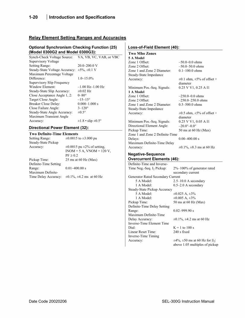
Volts/Hertz Over-Excitation Element (24): Definite-Time Element Pickup Range: 100200% Steady-State Pickup Accuracy: ±1% Pickup Time: 25 ms at 60 Hz (Max) Definite-Time Pickup Range: 0.00400.00 s Time-Delay Accuracy: ±0.1%, ±4.2 ms at 60 Hz
(Max) Composite-Time Element Inverse-Time Pickup Range: 100200% Inverse-Time Curve: 0.5, 1.0, or 2.0 Inverse-Time Dial: 0.110.0 s Inverse-Time Steady-State Pickup Accuracy: ±1% Inverse-Time Timing Accuracy: ±4%, ±25 ms at 60 Hz, for
V/Hz above 1.2 multiples of pickup setting
Definite-Time Pickup Range: 100200% Definite-Time Setting Range: 0.00400.00 s Pickup Time: 25 ms at 60 Hz (Max) Definite-Time Delay Accuracy: ±0.1%, ±4.2 ms at 60 Hz Linear Reset Time: 0.00400.00 s
1-20 Introduction and Specifications
Date Code 20020206 SEL-300G Instruction Manual
Relay Element Setting Ranges and Accuracies
Optional Synchronism Checking Function (25) (Model 0300G2 and Model 0300G3): Synch-Check Voltage Source: VA, VB, VC, VAB, or VBC Supervisory Voltage Setting Range: 20.0200.0 V Steady-State Voltage Accuracy: ±5%, ±0.1 V Maximum Percentage Voltage Difference: 1.015.0% Supervisory Slip Frequency Window Element: 1.00 Hz1.00 Hz Steady-State Slip Accuracy: ±0.02 Hz Close Acceptance Angle 1, 2: 080° Target Close Angle: 1515° Breaker Close Delay: 0.0001.000 s Close Failure Angle: 3120° Steady-State Angle Accuracy: ±0.5° Maximum Transient Angle Accuracy: ±1.8 slip ±0.5°
Directional Power Element (32): Two Definite-Time Elements Setting Range: ±0.0015 to ±3.000 pu Steady-State Pickup Accuracy:
±0.0015 pu ±2% of setting, INOM = 5 A, VNOM = 120 V, PF ≥ 0.2
Pickup Time: 25 ms at 60 Hz (Max) Definite-Time Setting Range: 0.01400.00 s Maximum Definite-Time Delay Accuracy: ±0.1%, ±4.2 ms at 60 Hz
Loss-of-Field Element (40): Two Mho Zones 5 A Model Zone 1 Offset: 50.00.0 ohms Zone 2 Offset: 50.050.0 ohms Zone 1 and Zone 2 Diameter: 0.1100.0 ohms Steady-State Impedance Accuracy:
±0.1 ohm, ±5% of offset + diameter
Minimum Pos.-Seq. Signals: 0.25 V V1, 0.25 A I1 1 A Model Zone 1 Offset: 250.00.0 ohms Zone 2 Offset: 250.0250.0 ohms Zone 1 and Zone 2 Diameter: 0.5500.0 ohms Steady-State Impedance Accuracy:
±0.5 ohm, ±5% of offset + diameter
Minimum Pos.-Seq. Signals: 0.25 V V1, 0.05 A I1 Directional Element Angle: 20.0°0.0° Pickup Time: 50 ms at 60 Hz (Max) Zone 1 and Zone 2 Definite-Time Delays:
0.00400.00 s
Maximum Definite-Time Delay Accuracy:
±0.1%, ±8.3 ms at 60 Hz
Negative-Sequence Overcurrent Elements (46): Definite-Time and Inverse-Time Neg.-Seq. I2 Pickup:
2%100% of generator rated secondary current
Generator Rated Secondary Current 5 A Model: 2.510.0 A secondary 1 A Model: 0.52.0 A secondary Steady-State Pickup Accuracy 5 A Model: ±0.025 A, ±3% 1 A Model: ±0.005 A, ±3% Pickup Time: 50 ms at 60 Hz (Max) Definite-Time Delay Setting Range:
0.02999.90 s
Maximum Definite-Time Delay Accuracy:
±0.1%, ±4.2 ms at 60 Hz
Inverse-Time Element Time Dial:
K = 1 to 100 s
Linear Reset Time: 240 s fixed Inverse-Time Timing Accuracy:
±4%, ±50 ms at 60 Hz for |I2| above 1.05 multiples of pickup

Introduction and Specifications 1-21
SEL-300G Instruction Manual Date Code 20020206
Relay Element Setting Ranges and Accuracies
Instantaneous / Definite-Time Overcurrent Elements (50): Phase, Residual Ground, Neutral Protection Current Pickup (A secondary) 5 A Model: 0.25100.00 1 A Model: 0.0520.00 Steady-State Pickup Accuracy 5 A Model: ±0.05 A, ±3% 1 A Model: ±0.01 A, ±3% Transient Overreach: ±5% of pickup Pickup Time: 25 ms at 60 Hz (Max) Note: 50 ms for 50Q element. Time Delay: 0.00400.00 s Timer Accuracy: ±0.1%, ±4.2 ms at 60 Hz
Inverse Time-Overcurrent Elements (51): Residual Ground and Neutral Protection Current Pickup (A secondary) 5 A Model: 0.516.0 1 A Model: 0.13.2 A Steady-State Pickup Accuracy 5 A Model: ±0.05 A, ±3% 1 A Model: ±0.01 A, ±3% Time Dials US: 0.515.0, 0.01 steps IEC: 0.051.00, 0.01 steps Timing: ±4%, ±25 ms at 60 Hz for |I| between 2 and 20
multiples of pickup
Voltage Restrained Phase Time-Overcurrent Element (51V): Phase Pickup (A secondary) 5 A Model: 2.016.0 1 A Model: 0.43.2 Steady-State Pickup Accuracy 5 A Model: ±0.05 A, ±3% 1 A Model: ±0.01 A, ±3% Time Dials US: 0.515.0, 0.01 steps IEC: 0.051.00, 0.01 steps Timing: ±4%, ±25 ms at 60 Hz for |I| between 2 and 20
multiples of pickup Voltage Restraint Type: Linear restraint
Voltage Controlled Phase Time-Overcurrent Element (51C): Phase Pickup (A secondary) 5 A Model: 0.516.0 1 A Model: 0.13.2 Steady State Pickup Accuracy 5 A Model: ±0.05 A, ±3% 1 A Model: ±0.01 A, ±3% Time Dials US: 0.515.0, 0.01 steps IEC: 0.051.00, 0.01 steps Timing: ±4%, ±25 ms for |I| between 2 and 20 multiples
of pickup
Instantaneous / Definite-Time Under- (27) / Overvoltage (59) Elements: Phase and Residual 27/59: 0.0200.0 V Phase-to-Phase 27/59: 0.0200.0 V Pos.-, Neg.-, and Zero-Sequence 59: 0.0200.0 V Steady-State Pickup Accuracy: ±5%, ±0.1 V SELOGIC Control Equation Time-Delay Setting Range: 0.003000.00 s Desired time delay may be added using SELOGIC Control Equation Timers.
100 Percent Stator Ground Protection (64G): Neutral Fundamental Overvoltage 64G1: 0.0150.0 V Steady-State Pickup Accuracy: ±5%, ±0.1 V Pickup Time: 25 ms at 60 Hz (Max) Definite-Time Delay: 0.00400.00 s Maximum Definite-Time Delay Accuracy: ±0.1%, ±4.2 ms at 60 Hz Third-Harmonic Voltage Differential or Third-Harmonic Neutral Undervoltage Pickup 64G2: 0.120.0 V Steady-State Pickup Accuracy: ±5%, ±0.1 V Third-Harmonic Voltage Differential Ratio Setting Range: 0.0 to 5.0 Pickup Time: 50 ms at 60 Hz (Max) Definite-Time Delay: 0.00400.00 s Maximum Definite-Time Delay Accuracy: ±0.1%, ±4.2 ms at 60 Hz
1-22 Introduction and Specifications
Date Code 20020206 SEL-300G Instruction Manual
Relay Element Setting Ranges and Accuracies
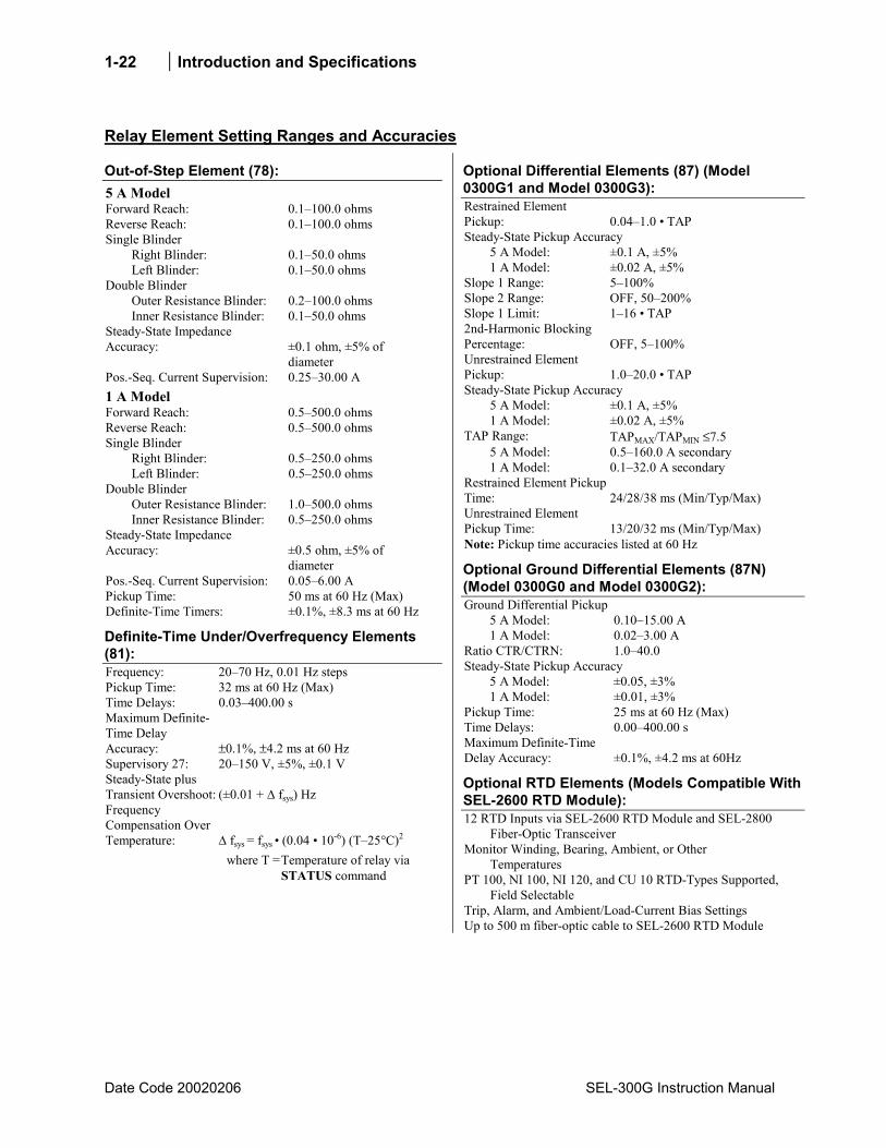
Out-of-Step Element (78): 5 A Model Forward Reach: 0.1100.0 ohms Reverse Reach: 0.1100.0 ohms Single Blinder Right Blinder: 0.150.0 ohms Left Blinder: 0.150.0 ohms Double Blinder Outer Resistance Blinder: 0.2100.0 ohms Inner Resistance Blinder: 0.150.0 ohms Steady-State Impedance Accuracy:
±0.1 ohm, ±5% of diameter
Pos.-Seq. Current Supervision: 0.2530.00 A 1 A Model Forward Reach: 0.5500.0 ohms Reverse Reach: 0.5500.0 ohms Single Blinder Right Blinder: 0.5250.0 ohms Left Blinder: 0.5250.0 ohms Double Blinder Outer Resistance Blinder: 1.0500.0 ohms Inner Resistance Blinder: 0.5250.0 ohms Steady-State Impedance Accuracy:
±0.5 ohm, ±5% of diameter
Pos.-Seq. Current Supervision: 0.056.00 A Pickup Time: 50 ms at 60 Hz (Max) Definite-Time Timers: ±0.1%, ±8.3 ms at 60 Hz
Definite-Time Under/Overfrequency Elements (81): Frequency: 2070 Hz, 0.01 Hz steps Pickup Time: 32 ms at 60 Hz (Max) Time Delays: 0.03400.00 s Maximum Definite-Time Delay Accuracy: ±0.1%, ±4.2 ms at 60 Hz Supervisory 27: 20150 V, ±5%, ±0.1 V Steady-State plus Transient Overshoot: (±0.01 + ∆ fsys) Hz Frequency Compensation Over Temperature: ∆ fsys = fsys (0.04 10-6) (T25°C)2
where T = Temperature of relay via STATUS command
Optional Differential Elements (87) (Model 0300G1 and Model 0300G3): Restrained Element Pickup: 0.041.0 TAP Steady-State Pickup Accuracy 5 A Model: ±0.1 A, ±5% 1 A Model: ±0.02 A, ±5% Slope 1 Range: 5100% Slope 2 Range: OFF, 50200% Slope 1 Limit: 116 TAP 2nd-Harmonic Blocking Percentage: OFF, 5100% Unrestrained Element Pickup: 1.020.0 TAP Steady-State Pickup Accuracy 5 A Model: ±0.1 A, ±5% 1 A Model: ±0.02 A, ±5% TAP Range: TAPMAX/TAPMIN ≤7.5 5 A Model: 0.5160.0 A secondary 1 A Model: 0.132.0 A secondary Restrained Element Pickup Time: 24/28/38 ms (Min/Typ/Max) Unrestrained Element Pickup Time: 13/20/32 ms (Min/Typ/Max) Note: Pickup time accuracies listed at 60 Hz
Optional Ground Differential Elements (87N) (Model 0300G0 and Model 0300G2): Ground Differential Pickup 5 A Model: 0.1015.00 A 1 A Model: 0.023.00 A Ratio CTR/CTRN: 1.040.0 Steady-State Pickup Accuracy 5 A Model: ±0.05, ±3% 1 A Model: ±0.01, ±3% Pickup Time: 25 ms at 60 Hz (Max) Time Delays: 0.00400.00 s Maximum Definite-Time Delay Accuracy: ±0.1%, ±4.2 ms at 60Hz
Optional RTD Elements (Models Compatible With SEL-2600 RTD Module): 12 RTD Inputs via SEL-2600 RTD Module and SEL-2800 Fiber-Optic Transceiver Monitor Winding, Bearing, Ambient, or Other Temperatures PT 100, NI 100, NI 120, and CU 10 RTD-Types Supported, Field Selectable Trip, Alarm, and Ambient/Load-Current Bias Settings Up to 500 m fiber-optic cable to SEL-2600 RTD Module
Introduction and Specifications 1-23
SEL-300G Instruction Manual Date Code 20020206
Relay Element Setting Ranges and Accuracies
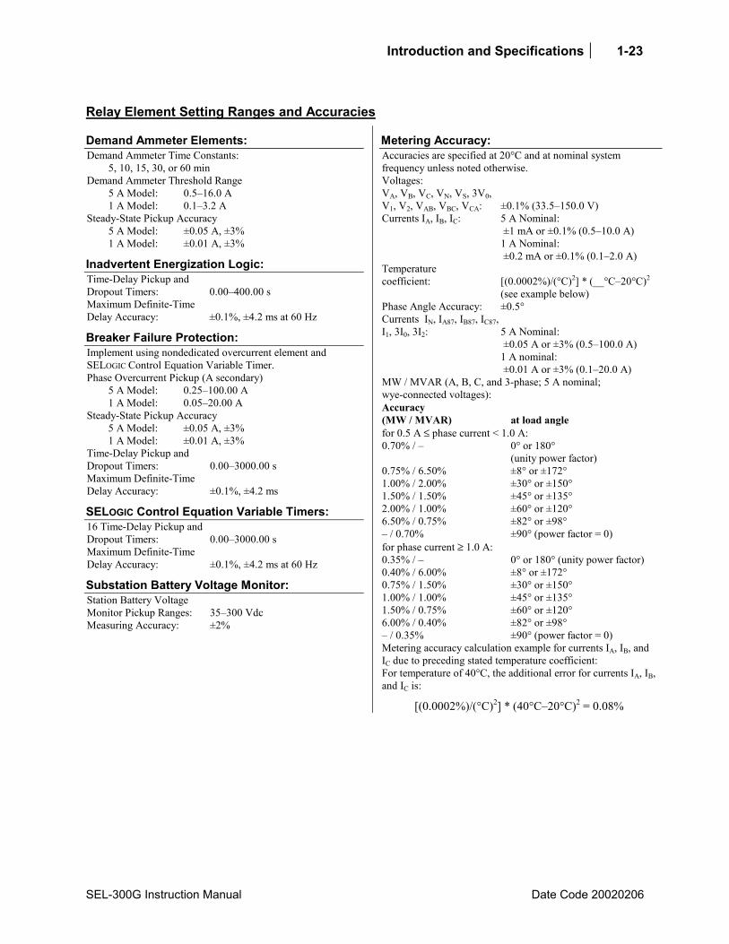
Demand Ammeter Elements: Demand Ammeter Time Constants: 5, 10, 15, 30, or 60 min Demand Ammeter Threshold Range 5 A Model: 0.516.0 A 1 A Model: 0.13.2 A Steady-State Pickup Accuracy 5 A Model: ±0.05 A, ±3% 1 A Model: ±0.01 A, ±3%
Inadvertent Energization Logic: Time-Delay Pickup and Dropout Timers: 0.00400.00 s Maximum Definite-Time Delay Accuracy: ±0.1%, ±4.2 ms at 60 Hz
Breaker Failure Protection: Implement using nondedicated overcurrent element and SELOGIC Control Equation Variable Timer. Phase Overcurrent Pickup (A secondary) 5 A Model: 0.25100.00 A 1 A Model: 0.0520.00 A Steady-State Pickup Accuracy 5 A Model: ±0.05 A, ±3% 1 A Model: ±0.01 A, ±3% Time-Delay Pickup and Dropout Timers: 0.003000.00 s Maximum Definite-Time Delay Accuracy: ±0.1%, ±4.2 ms
SELOGIC Control Equation Variable Timers: 16 Time-Delay Pickup and Dropout Timers: 0.003000.00 s Maximum Definite-Time Delay Accuracy: ±0.1%, ±4.2 ms at 60 Hz
Substation Battery Voltage Monitor: Station Battery Voltage Monitor Pickup Ranges: 35300 Vdc Measuring Accuracy: ±2%
Metering Accuracy: Accuracies are specified at 20°C and at nominal system frequency unless noted otherwise. Voltages: VA, VB, VC, VN, VS, 3V0, V1, V2, VAB, VBC, VCA: ±0.1% (33.5150.0 V) Currents IA, IB, IC: 5 A Nominal:
±1 mA or ±0.1% (0.510.0 A) 1 A Nominal: ±0.2 mA or ±0.1% (0.12.0 A)
Temperature coefficient:
[(0.0002%)/(°C)2] * (__°C20°C)2 (see example below)
Phase Angle Accuracy: ±0.5° 5 A Nominal: ±0.05 A or ±3% (0.5100.0 A)
Currents IN, IA87, IB87, IC87, I1, 3I0, 3I2:
1 A nominal: ±0.01 A or ±3% (0.120.0 A)
MW / MVAR (A, B, C, and 3-phase; 5 A nominal; wye-connected voltages): Accuracy (MW / MVAR)
at load angle
for 0.5 A ≤ phase current < 1.0 A: 0.70% / 0° or 180°
(unity power factor) 0.75% / 6.50% ±8° or ±172° 1.00% / 2.00% ±30° or ±150° 1.50% / 1.50% ±45° or ±135° 2.00% / 1.00% ±60° or ±120° 6.50% / 0.75% ±82° or ±98° / 0.70% ±90° (power factor = 0) for phase current ≥ 1.0 A: 0.35% / 0° or 180° (unity power factor) 0.40% / 6.00% ±8° or ±172° 0.75% / 1.50% ±30° or ±150° 1.00% / 1.00% ±45° or ±135° 1.50% / 0.75% ±60° or ±120° 6.00% / 0.40% ±82° or ±98° / 0.35% ±90° (power factor = 0) Metering accuracy calculation example for currents IA, IB, and IC due to preceding stated temperature coefficient: For temperature of 40°C, the additional error for currents IA, IB, and IC is:
[(0.0002%)/(°C)2] * (40°C20°C)2 = 0.08%

SEL-300G Instruction Manual Date Code 20020206
TABLE OF CONTENTS
SECTION 2: RELAY ELEMENT SETTINGS ..........................................2-1
Relay Functional Overview...........................................................................................................2-1 Data Acquisition and Filtering ..............................................................................................2-1 Element Processing ...............................................................................................................2-2 Relay Word ...........................................................................................................................2-2 SELOGIC® Control Equations................................................................................................2-2 Background Tasks .................................................................................................................2-2
Relay Settings Overview...............................................................................................................2-2 Protection Element Selection Guidelines......................................................................................2-5 Relay Configuration Settings ........................................................................................................2-6
Group 1, Group 2 Configuration Setting Descriptions .........................................................2-6 Global Configuration Setting Descriptions (SET G) ............................................................2-9
Setting Group Selection...............................................................................................2-11 BKR Monitor...............................................................................................................2-11 Optioisolated Input Timers..........................................................................................2-11 Local Bit Settings ........................................................................................................2-11 Display Point Settings .................................................................................................2-11
Phase Mho Distance Element .....................................................................................................2-11 Element Description............................................................................................................2-11
Functional Description ................................................................................................2-11 Setting Descriptions ....................................................................................................2-12 Relay Word Bits ..........................................................................................................2-14
Setting Calculation ..............................................................................................................2-14 Information Needed.....................................................................................................2-14 Recommendations .......................................................................................................2-14 Phase Distance Tripping..............................................................................................2-15
Element Operating Characteristics......................................................................................2-16 Volts/Hertz Element....................................................................................................................2-17
Element Description............................................................................................................2-17 Functional Description ................................................................................................2-17 Setting Descriptions ....................................................................................................2-18 Relay Word Bits ..........................................................................................................2-20
Setting Calculation ..............................................................................................................2-20 Information Needed.....................................................................................................2-20 Recommendations .......................................................................................................2-20 Volts/Hertz Tripping ...................................................................................................2-20
Element Operating Characteristics......................................................................................2-21 Reverse/Low-Forward Power Element .......................................................................................2-25
Element Description............................................................................................................2-25 Functional Description ................................................................................................2-25 Setting Descriptions ....................................................................................................2-26 Relay Word Bits ..........................................................................................................2-27
Setting Calculation ..............................................................................................................2-27 Information Needed.....................................................................................................2-27

ii Relay Element Settings
Date Code 20020206 SEL-300G Instruction Manual
Recommendations .......................................................................................................2-27 Reverse-Power Tripping..............................................................................................2-28
Element Operating Characteristics......................................................................................2-28 Loss-of-Field Element.................................................................................................................2-29
Element Description............................................................................................................2-29 Functional Description ................................................................................................2-29 Setting Descriptions ....................................................................................................2-30 Relay Word Bits ..........................................................................................................2-31
Setting Calculation ..............................................................................................................2-32 Information Needed.....................................................................................................2-32 Recommendations .......................................................................................................2-32
Loss-of-Field Protection Using a Negative Offset Zone 2 ..................................2-32 Loss-of-Field Protection Using a Positive Offset Zone 2....................................2-33
Element Operating Characteristics......................................................................................2-34 Negative-Sequence Overcurrent Elements..................................................................................2-35
Element Description............................................................................................................2-35 Functional Description ................................................................................................2-35 Setting Descriptions ....................................................................................................2-35 Relay Word Bits ..........................................................................................................2-36
Setting Calculation ..............................................................................................................2-37 Information Needed.....................................................................................................2-37 Recommendations .......................................................................................................2-37 Negative-Sequence Overcurrent Tripping...................................................................2-37
Element Operating Characteristics......................................................................................2-38 Overcurrent Elements..................................................................................................................2-40
Element Description............................................................................................................2-40 Functional Description ................................................................................................2-40
Overcurrent Protection, All Relay Models ..........................................................2-40 Overcurrent Protection, Relay Models With Differential Protection..................2-40
Setting Descriptions ....................................................................................................2-41 Definite-Time Overcurrent Settings ....................................................................2-41 Definite-Time 50/87 Overcurrent Settings ..........................................................2-42 Neutral Time-Overcurrent Settings .....................................................................2-42 Residual Time-Overcurrent Settings ...................................................................2-43
Relay Word Bits ..........................................................................................................2-43 Neutral Overcurrent Setting Calculation.............................................................................2-45
Information Needed.....................................................................................................2-45 Recommendations .......................................................................................................2-45 Neutral Overcurrent Tripping......................................................................................2-46 Other Overcurrent Elements........................................................................................2-46
Element Operating Characteristics......................................................................................2-46 Pickup and Reset Time Curves....................................................................................2-46
Time-Overcurrent Curves ...........................................................................................................2-51 U.S. Moderately Inverse Curve: U1 ...........................................................................2-51 I.E.C. Class A Curve (Standard Inverse): C1 .............................................................2-51 U.S. Inverse Curve: U2...............................................................................................2-51 I.E.C. Class B Curve (Very Inverse): C2 ...................................................................2-51 U.S. Very Inverse Curve: U3......................................................................................2-51 I.E.C. Class C Curve (Extremely Inverse): C3...........................................................2-51 U.S. Extremely Inverse Curve: U4.............................................................................2-51
Relay Element Settings iii
SEL-300G Instruction Manual Date Code 20020206
I.E.C. Long-Time Inverse Curve: C4 .........................................................................2-51 U.S. Short-Time Inverse Curve: U5 ...........................................................................2-51
Voltage-Controlled/Restrained Time-Overcurrent Elements .......................................................2-4 Element Description..............................................................................................................2-4
Functional Description ..................................................................................................2-4 Setting Descriptions ......................................................................................................2-5 Relay Word Bits ............................................................................................................2-6
Voltage-Controlled and Voltage-Restrained Time-Overcurrent Setting Calculation ...........2-6 Information Needed.......................................................................................................2-6 Recommendations .........................................................................................................2-6
Voltage-Controlled Time-Overcurrent Settings ....................................................2-6 Voltage-Restrained Time-Overcurrent Settings ....................................................2-7
Overcurrent Tripping.....................................................................................................2-8 Element Operating Characteristics........................................................................................2-8
Over/Under Voltage Elements ....................................................................................................2-10 Element Description............................................................................................................2-10
Functional Description ................................................................................................2-10 Setting Descriptions ....................................................................................................2-10 Relay Word Bits ..........................................................................................................2-11
Voltage Element Setting Calculation ..................................................................................2-11 Loss-of-Potential (60LOP) Protection ........................................................................................2-14
Element Description............................................................................................................2-14 Functional Description ................................................................................................2-14 Setting Descriptions ....................................................................................................2-14 Relay Word Bits ..........................................................................................................2-14
100% Stator Ground Protection Elements ..................................................................................2-14 Element Description............................................................................................................2-14
Functional Description ................................................................................................2-14 Setting Descriptions ....................................................................................................2-16 Relay Word Bits ..........................................................................................................2-17
100% Stator Ground Protection Setting Calculation ..........................................................2-17 Information Needed.....................................................................................................2-17 Third-Harmonic Voltage Differential Setting Recommendations (four-wire
potentials required)..............................................................................................2-17 Third-Harmonic Neutral Undervoltage Setting Recommendations (use with
open-delta potentials) ..........................................................................................2-19 100% Stator Ground Fault Tripping............................................................................2-21
Element Operating Characteristics......................................................................................2-21 Out-of-Step ElementSingle Blinder Scheme.............................................................................2-22
Element Description............................................................................................................2-22 Functional Description ................................................................................................2-22 Setting Descriptions ....................................................................................................2-25 Relay Word Bits ..........................................................................................................2-26
Settings Calculation ............................................................................................................2-26 Information Needed.....................................................................................................2-26 Recommendations .......................................................................................................2-26
Out-of-Step ElementDouble Blinder Scheme ...........................................................................2-28 Element Description............................................................................................................2-28
Functional Description ................................................................................................2-28 Settings Descriptions...................................................................................................2-31
iv Relay Element Settings
Date Code 20020206 SEL-300G Instruction Manual
Relay Word Bits ..........................................................................................................2-32 Settings Calculation ............................................................................................................2-32
Information Needed.....................................................................................................2-32 Recommendations .......................................................................................................2-32
Frequency Protection ..................................................................................................................2-35 Element Description............................................................................................................2-35
Functional Description ................................................................................................2-35 Setting Descriptions ....................................................................................................2-35 Relay Word Bits ..........................................................................................................2-36
Frequency Element Setting Calculation..............................................................................2-36 Information Needed.....................................................................................................2-36 Recommendations .......................................................................................................2-36 Underfrequency Tripping ............................................................................................2-37
Element Operating Characteristics......................................................................................2-37 Off-Frequency Accumulators......................................................................................................2-39
Element Description............................................................................................................2-39 Functional Description ................................................................................................2-39 Setting Descriptions ....................................................................................................2-39
Abnormal Frequency Element Control Equation ................................................2-40 Relay Word Bits ..........................................................................................................2-40
Abnormal Frequency Protection Setting Calculation .........................................................2-41 Information Needed.....................................................................................................2-41 Recommendations .......................................................................................................2-41 Abnormal Frequency Tripping ....................................................................................2-41
Element Operating Characteristics......................................................................................2-42 RTD-Based Protection (Models Compatible With SEL-2600 RTD Module) ...........................2-44
Element Description............................................................................................................2-44 Functional Description ................................................................................................2-44 Setting Descriptions ....................................................................................................2-44
RTD Configuration Settings................................................................................2-44 RTD Location Settings ........................................................................................2-44 RTD Type Settings ..............................................................................................2-45 RTD Alarms & Trip Temperature Settings .........................................................2-46
Relay Word Bits ..........................................................................................................2-50 Pole Open Logic..........................................................................................................................2-51
Element Description............................................................................................................2-51 Functional Description ................................................................................................2-51 Setting Descriptions ....................................................................................................2-51 Relay Word Bits ..........................................................................................................2-51
Pole Open Logic Setting Calculation ..................................................................................2-52 Recommendations .......................................................................................................2-52
Inadvertent Energization Protection............................................................................................2-52 Breaker Failure Protection ..........................................................................................................2-52 Differential Protection ................................................................................................................2-52 Synchronism Checking ...............................................................................................................2-52
Relay Element Settings v
SEL-300G Instruction Manual Date Code 20020206
TABLES Table 2.1: Recommended Protection Elements by Generator Grounding Method................................2-5 Table 2.2: RTD Resistance vs. Temperature .......................................................................................2-49
FIGURES Figure 2.1: Relay Processing Order.........................................................................................................2-1 Figure 2.2: SEL-300G Relay Setting Categories.....................................................................................2-3 Figure 2.3: PTRN, CTRN Setting Examples...........................................................................................2-8 Figure 2.4: Phase Rotation Settings ......................................................................................................2-10 Figure 2.5 Distance Element Operating Characteristics ......................................................................2-16 Figure 2.6: Zone 1 Mho Element Logic ................................................................................................2-16 Figure 2.7: Phase Distance Element Logic............................................................................................2-17 Figure 2.8: Dual-Level Volts/Hertz Time-Delay Characteristic, 24CCS=DD......................................2-21 Figure 2.9: Composite Inverse/Definite-Time Overexcitation Characteristic, 24CCS=ID ..................2-21 Figure 2.10: Volts/Hertz Inverse-Time Characteristic, 24IC = 0.5.........................................................2-22 Figure 2.11: Volts/Hertz Inverse-Time Characteristic, 24IC = 1............................................................2-23 Figure 2.12: Volts/Hertz Inverse-Time Characteristics, 24IC = 2 ..........................................................2-24 Figure 2.13: Volts/Hertz Element Logic Diagram ..................................................................................2-25 Figure 2.14: Reverse/Low-Forward Power Element Operating Characteristic.......................................2-28 Figure 2.15: Reverse/Low-Forward Power Element Logic Diagram......................................................2-29 Figure 2.16: Loss-of-Field Logic Diagram..............................................................................................2-30 Figure 2.17: Loss-of-Field Element Operating Characteristic, Negative Zone 2 Offset.........................2-34 Figure 2.18: Loss-of-Field Element Operating Characteristic, Positive Zone 2 Offset ..........................2-35 Figure 2.19: Negative-Sequence Overcurrent Element Logic Diagram..................................................2-38 Figure 2.20: Negative-Sequence Time-Overcurrent Operating Characteristic .......................................2-39 Figure 2.21: Instantaneous Overcurrent Element Pickup Time Curve....................................................2-47 Figure 2.22: Instantaneous Overcurrent Element Reset Time Curve......................................................2-47 Figure 2.23: Definite-Time Overcurrent Element Logic Diagram..........................................................2-48 Figure 2.24: 87-Input Definite-Time Overcurrent Element Logic Diagram ...........................................2-49 Figure 2.25: Neutral Ground Time-Overcurrent Element 51NT.............................................................2-50 Figure 2.26: Residual Ground Time-Overcurrent Element 51GT...........................................................2-50 Figure 2.27: U.S. Moderately Inverse Curve: U1.....................................................................................2-2 Figure 2.28: U.S. Inverse Curve: U2 ........................................................................................................2-2 Figure 2.29: U.S. Very Inverse Curve: U3 ...............................................................................................2-2 Figure 2.30: U.S. Extremely Inverse Curve: U4 .....................................................................................2-2 Figure 2.31: U.S. Short-Time Inverse Curve: U5.....................................................................................2-3 Figure 2.32: I.E.C. Class A Curve (Standard Inverse): C1 ......................................................................2-3 Figure 2.33: I.E.C. Class B Curve (Very Inverse): C2.............................................................................2-3 Figure 2.34: I.E.C. Class C Curve (Extremely Inverse): C3 ...................................................................2-3 Figure 2.35: I.E.C. Long-Time Inverse Curve: C4...................................................................................2-4 Figure 2.36: I.E.C. Short-Time Inverse Curve: C5...................................................................................2-4 Figure 2.37: Voltage-Controlled Phase Time-Overcurrent Element 51CT...............................................2-8 Figure 2.38: Voltage-Restrained Phase Time-Overcurrent Element 51VT ..............................................2-9 Figure 2.39: 51V Element Voltage Restraint Characteristic.....................................................................2-9 Figure 2.40: Undervoltage Element Logic Diagram ...............................................................................2-12 Figure 2.41: Overvoltage Element Logic Diagram .................................................................................2-13 Figure 2.42: 64G Element Operating Characteristic ...............................................................................2-15 Figure 2.43: 64G Logic Diagram ............................................................................................................2-21

vi Relay Element Settings
Date Code 20020206 SEL-300G Instruction Manual
Figure 2.44: Single Blinder Scheme Operating Characteristics..............................................................2-22 Figure 2.45: Single Blinder Scheme Logic Diagram ..............................................................................2-24 Figure 2.46: Single Blinder Typical Settings ..........................................................................................2-27 Figure 2.47: Double Blinder Scheme Operating Characteristics ............................................................2-28 Figure 2.48: Double Blinder Scheme Logic Diagram.............................................................................2-30 Figure 2.49: Double Blinder Typical Settings.........................................................................................2-34 Figure 2.50: Frequency Element Voltage Supervision Logic .................................................................2-37 Figure 2.51: Frequency Element Logic ...................................................................................................2-38 Figure 2.52: Example Turbine Operating Limitations During Abnormal Frequency.............................2-42 Figure 2.53: Abnormal Frequency Protection Logic Diagram................................................................2-43 Figure 2.54: Winding RTD Trip Characteristics with BLMT = 2.00 .....................................................2-48 Figure 2.55: Pole Open Logic Diagram...................................................................................................2-51
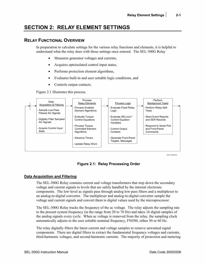
Relay Element Settings 2-1
SEL-300G Instruction Manual Date Code 20020206
SECTION 2: RELAY ELEMENT SETTINGS
RELAY FUNCTIONAL OVERVIEW In preparation to calculate settings for the various relay functions and elements, it is helpful to understand what the relay does with those settings once entered. The SEL-300G Relay
• Measures generator voltages and currents,
• Acquires optoisolated control input states,
• Performs protection element algorithms,
• Evaluates built-in and user settable logic conditions, and
• Controls output contacts.
Figure 2.1 illustrates this process.
DWG: M300G039
Data Acquisition & Filtering
- Sample Low-Pass Filtered AC Signals
- Digitally Filter Sampled AC Signals
- Acquire Control Input State
ProcessRelay Elements
- Process Enabled Element Algorithms
- Evaluate Torque- Control Equations
- Process Torque- Controlled Element Algorithms
- Advance Timers
- Update Relay Word
Process Logic
- Evaluate Fixed Relay Logic
- Evaluate SELOGIC
Control Equation Variables
- Control Output Contacts
- Generate Front-Panel Targets, Messages
PerformBackground Tasks
- Perform Relay Self- Tests
- Store Event Reports and SER Records
- Respond to Serial Port and Front-Panel Commands
Figure 2.1: Relay Processing Order
Data Acquisition and Filtering The SEL-300G Relay contains current and voltage transformers that step down the secondary voltage and current signals to levels that are safely handled by the internal electronic components. The low-level ac signals pass through analog low-pass filters and a multiplexer to an analog-to-digital converter. The multiplexer and analog-to-digital converter sample the voltage and current signals and convert them to digital values used by the microprocessor.
The SEL-300G Relay tracks the frequency of the ac voltage. The relay adjusts the sampling rate to the present system frequency (in the range from 20 to 70 Hz) and takes 16 digital samples of the analog signals every cycle. When ac voltage is removed from the relay, the sampling clock automatically adjusts to the user settable nominal frequency, FNOM, either 50 or 60 Hz.
The relay digitally filters the latest current and voltage samples to remove unwanted signal components. There are digital filters to extract the fundamental frequency voltages and currents, third-harmonic voltages, and second-harmonic currents. The majority of protection and metering

2-2 Relay Element Settings
Date Code 20020206 SEL-300G Instruction Manual
functions use fundamental frequency voltages and currents. The 100% stator ground protection function uses third-harmonic voltages. When differential elements are included, the second-harmonic blocking function uses the second-harmonic currents. At this time, the relay also checks the optoisolated inputs to determine if any are asserted.
Element Processing Having acquired and filtered the voltage and current signals, the relay next evaluates the enabled protection elements. Some elements are supervised by a torque-control setting. In this case, the equation result must be a logical 1 for the element to operate. Element timers are advanced at this point.
The out-of-step and loss-of-field elements are processed twice per power system cycle and the RTD elements once in two seconds. Other elements are processed four times per power system cycle.
Relay Word As the relay processes the protection element algorithms and evaluates the fixed logic, if an element is picked up or a logic condition is true, the relay changes the state of the associated Relay Word bit from a logical 0 to a logical 1. The relay uses these results to evaluate SELOGIC® Control Equations defined in the relay settings.
SELOGIC® Control Equations After evaluating the fixed logic, the relay evaluates the SELOGIC Control Equations, and then controls the relay output contacts.
Background Tasks By design, there is always processing time left after the relay controls its output contacts and before it begins digitally filtering acquired signals again. During this free time, the relay performs background tasks such as:
• Self testing,
• Event report and SER record storage, and
• Responding to serial port and front-panel commands.
RELAY SETTINGS OVERVIEW You configure the SEL-300G Relay generator protection and monitoring functions by entering settings in three categories, described by Figure 2.2.

Relay Element Settings 2-3
SEL-300G Instruction Manual Date Code 20020206
DWG: M300G040
Commands
SET1, SHOWSET1SET2, SHOWSET2
SET G, SHOWSET G
SET R, SHOWSET R
Group 1 Settings
Generator Nominal SettingsElement EnablesElement SettingsDemand Ammeter SettingsSELOGIC Control EquationsSELOGIC Control Equation Latch SettingsTRIP, CLOSE, ER SettingsOutput Settings
SER Settings
SER1 - SER4 SettingsALIAS Settings
Global Settings
Event Report Format SettingsNominal Frequency SettingPT Connection SettingSetting Group Selection SettingsBreaker Monitor SettingsInput Debounce TimersLocal Bit SettingsFront-Panel Display SettingsDisplay Point Settings
Group 2 Settings
Generator Nominal SettingsElement EnablesElement SettingsDemand Ammeter SettingsSELOGIC Control EquationsSELOGIC Control Equation Latch SettingsTRIP, CLOSE, ER SettingsOutput Settings
Figure 2.2: SEL-300G Relay Setting Categories
The relay is equipped with two protection element setting groups, Group 1 and Group 2. Group 1 and Group 2 contain
• Enable settings for specific protection elements,
• Settings to define element pickups and time delays,
• SELOGIC Control Equation element torque controls,
• SELOGIC Control Equation event report triggers,
• Nondedicated SELOGIC Control Equation timers and latches,
• SELOGIC Control Equations for trip and close signals, and
• SELOGIC Control Equations for relay output contacts.
2-4 Relay Element Settings
Date Code 20020206 SEL-300G Instruction Manual
The relay protects the generator using one setting group at a time. You control which setting group is enabled using serial port commands and settings provided in the Global setting category. The relay always uses the Global settings, regardless of which setting group presently is enabled.
The Global settings define:
• SELOGIC Control Equations for setting group selection,
• Breaker monitor function settings,
• Optoisolated input debounce timer settings,
• Local bit settings,
• Front-panel display settings, and
• Display point settings.
Settings configuring the relay Sequential Events Recorder (SER) function are entered using the SET R command. These settings are always active, regardless of whether setting Group 1 or setting Group 2 is enabled.
This section of the instruction manual describes each protection function. The outputs from each function are defined, and setting recommendations or guidelines for their calculation are provided. Where appropriate, logic diagrams and element operating characteristic diagrams also are provided.
Section 3: Auxiliary Function Settings describes settings for the demand meter, dc monitor, setting group selection, breaker monitor, optoisolated input debounce timers, and the SER function settings.
Section 4: SELOGIC® Control Equations describes SELOGIC Control Equations in general, and the trip, close, event trigger, and output contact control equations in particular.
Refer to Section 6: Enter Relay Settings for complete relay Settings Sheets showing each of the relay settings and their ranges in the order that they are entered.
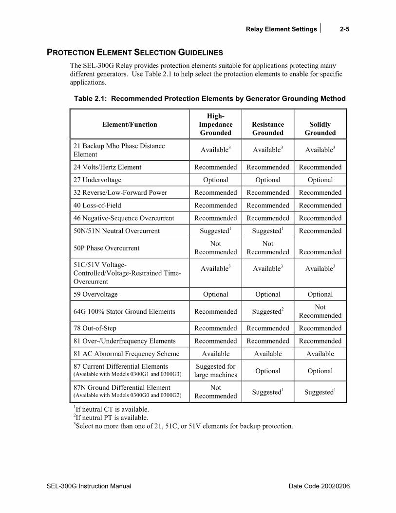
Relay Element Settings 2-5
SEL-300G Instruction Manual Date Code 20020206
PROTECTION ELEMENT SELECTION GUIDELINES The SEL-300G Relay provides protection elements suitable for applications protecting many different generators. Use Table 2.1 to help select the protection elements to enable for specific applications.
Table 2.1: Recommended Protection Elements by Generator Grounding Method
Element/Function
High-Impedance Grounded
Resistance Grounded
Solidly
Grounded
21 Backup Mho Phase Distance Element Available3 Available3 Available3
24 Volts/Hertz Element Recommended Recommended Recommended
27 Undervoltage Optional Optional Optional
32 Reverse/Low-Forward Power Recommended Recommended Recommended
40 Loss-of-Field Recommended Recommended Recommended
46 Negative-Sequence Overcurrent Recommended Recommended Recommended
50N/51N Neutral Overcurrent Suggested1 Suggested1 Recommended
50P Phase Overcurrent Not Recommended
Not Recommended Recommended
51C/51V Voltage-Controlled/Voltage-Restrained Time-Overcurrent
Available3 Available3 Available3
59 Overvoltage Optional Optional Optional
64G 100% Stator Ground Elements Recommended Suggested2 Not Recommended
78 Out-of-Step Recommended Recommended Recommended
81 Over-/Underfrequency Elements Recommended Recommended Recommended
81 AC Abnormal Frequency Scheme Available Available Available
87 Current Differential Elements (Available with Models 0300G1 and 0300G3)
Suggested for large machines Optional Optional
87N Ground Differential Element (Available with Models 0300G0 and 0300G2)
Not Recommended Suggested1 Suggested1
1If neutral CT is available. 2If neutral PT is available. 3Select no more than one of 21, 51C, or 51V elements for backup protection.
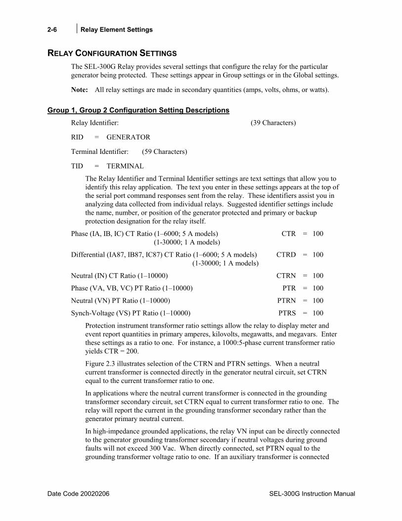
2-6 Relay Element Settings
Date Code 20020206 SEL-300G Instruction Manual
RELAY CONFIGURATION SETTINGS The SEL-300G Relay provides several settings that configure the relay for the particular generator being protected. These settings appear in Group settings or in the Global settings.
Note: All relay settings are made in secondary quantities (amps, volts, ohms, or watts).
Group 1, Group 2 Configuration Setting Descriptions Relay Identifier: (39 Characters)
RID = GENERATOR
Terminal Identifier: (59 Characters)
TID = TERMINAL
The Relay Identifier and Terminal Identifier settings are text settings that allow you to identify this relay application. The text you enter in these settings appears at the top of the serial port command responses sent from the relay. These identifiers assist you in analyzing data collected from individual relays. Suggested identifier settings include the name, number, or position of the generator protected and primary or backup protection designation for the relay itself.
Phase (IA, IB, IC) CT Ratio (16000; 5 A models) CTR = 100 (1-30000; 1 A models)
Differential (IA87, IB87, IC87) CT Ratio (16000; 5 A models) CTRD = 100 (1-30000; 1 A models)
Neutral (IN) CT Ratio (110000) CTRN = 100
Phase (VA, VB, VC) PT Ratio (110000) PTR = 100
Neutral (VN) PT Ratio (110000) PTRN = 100
Synch-Voltage (VS) PT Ratio (110000) PTRS = 100
Protection instrument transformer ratio settings allow the relay to display meter and event report quantities in primary amperes, kilovolts, megawatts, and megavars. Enter these settings as a ratio to one. For instance, a 1000:5-phase current transformer ratio yields CTR = 200.
Figure 2.3 illustrates selection of the CTRN and PTRN settings. When a neutral current transformer is connected directly in the generator neutral circuit, set CTRN equal to the current transformer ratio to one.
In applications where the neutral current transformer is connected in the grounding transformer secondary circuit, set CTRN equal to current transformer ratio to one. The relay will report the current in the grounding transformer secondary rather than the generator primary neutral current.
In high-impedance grounded applications, the relay VN input can be directly connected to the generator grounding transformer secondary if neutral voltages during ground faults will not exceed 300 Vac. When directly connected, set PTRN equal to the grounding transformer voltage ratio to one. If an auxiliary transformer is connected
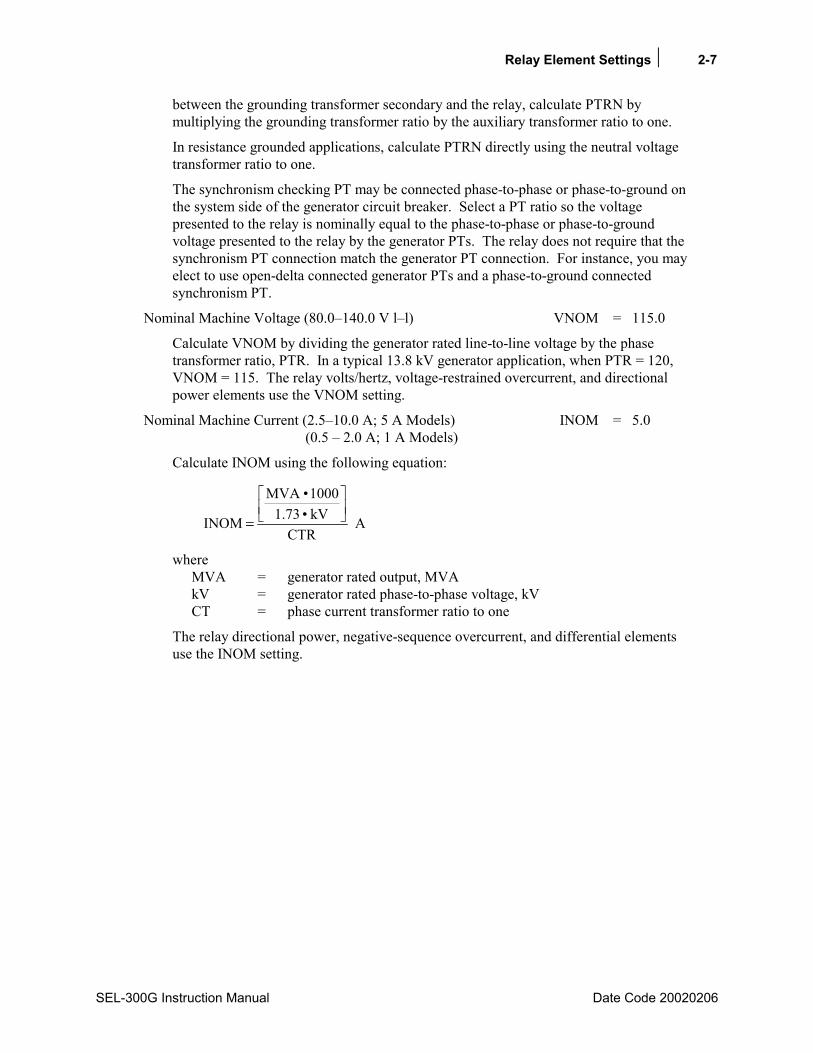
Relay Element Settings 2-7
SEL-300G Instruction Manual Date Code 20020206
between the grounding transformer secondary and the relay, calculate PTRN by multiplying the grounding transformer ratio by the auxiliary transformer ratio to one.
In resistance grounded applications, calculate PTRN directly using the neutral voltage transformer ratio to one.
The synchronism checking PT may be connected phase-to-phase or phase-to-ground on the system side of the generator circuit breaker. Select a PT ratio so the voltage presented to the relay is nominally equal to the phase-to-phase or phase-to-ground voltage presented to the relay by the generator PTs. The relay does not require that the synchronism PT connection match the generator PT connection. For instance, you may elect to use open-delta connected generator PTs and a phase-to-ground connected synchronism PT.
Nominal Machine Voltage (80.0140.0 V ll) VNOM = 115.0
Calculate VNOM by dividing the generator rated line-to-line voltage by the phase transformer ratio, PTR. In a typical 13.8 kV generator application, when PTR = 120, VNOM = 115. The relay volts/hertz, voltage-restrained overcurrent, and directional power elements use the VNOM setting.
Nominal Machine Current (2.510.0 A; 5 A Models) INOM = 5.0 (0.5 2.0 A; 1 A Models)
Calculate INOM using the following equation:
ACTR
kV73.11000MVA
INOM
=
where MVA = generator rated output, MVA kV = generator rated phase-to-phase voltage, kV CT = phase current transformer ratio to one
The relay directional power, negative-sequence overcurrent, and differential elements use the INOM setting.
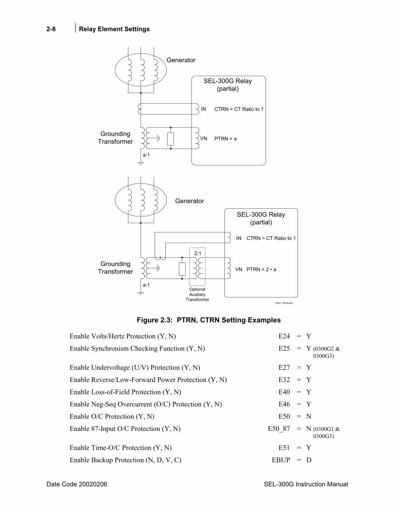
2-8 Relay Element Settings
Date Code 20020206 SEL-300G Instruction Manual
DWG: M300G041
Generator
GroundingTransformer
a:1
IN
VN
CTRN = CT Ratio to 1
PTRN = a
SEL-300G Relay(partial)
Generator
GroundingTransformer
a:1
IN
VN
CTRN = CT Ratio to 1
PTRN = 2 a
SEL-300G Relay(partial)
2:1
OptionalAuxiliary
Transformer
Figure 2.3: PTRN, CTRN Setting Examples
Enable Volts/Hertz Protection (Y, N) E24 = Y
Enable Synchronism Checking Function (Y, N) E25 = Y (0300G2 & 0300G3)
Enable Undervoltage (U/V) Protection (Y, N) E27 = Y
Enable Reverse/Low-Forward Power Protection (Y, N) E32 = Y
Enable Loss-of-Field Protection (Y, N) E40 = Y
Enable Neg-Seq Overcurrent (O/C) Protection (Y, N) E46 = Y
Enable O/C Protection (Y, N) E50 = N
Enable 87-Input O/C Protection (Y, N) E50_87 = N (0300G1 & 0300G3)
Enable Time-O/C Protection (Y, N) E51 = Y
Enable Backup Protection (N, D, V, C) EBUP = D

Relay Element Settings 2-9
SEL-300G Instruction Manual Date Code 20020206
Enable Overvoltage (O/V) Protection (Y, N) E59 = Y
Enable 100% Stator Ground Protection (Y, N) E64 = Y
Enable Out-of-Step Protection (1B, 2B, N) E78 = 1B
Enable Frequency Protection (N, 16) E81 = 2
Enable Abnormal Frequency Scheme (N, 16) E81AC = 6
Enable Differential Protection (G, T, N) E87 = G (0300G1 and 0300G3)
Enable Ground Differential Protection (Y, N) E87N = Y (0300G0 and 0300G2)
The settings above enable specific protection functions. These settings are described fully elsewhere in this section or in Section 13: Differential Element Setting.
Enable SELOGIC Control Equations (016) ESV = 6
Enable Set/Reset Latch Variables (016) ESL = 5
The ESV setting enables nondedicated SELOGIC Control Equation variables. Each variable is equipped with settable time-delay pickup and time-delay dropout timers. The ESL setting enables nondedicated SELOGIC Control Equation latch variables. Section 4: SELOGIC Control Equations fully describes these enables and their SELOGIC Control Equations.
Enable Demand Metering (THM, ROL) EDEM = ROL
The relay demand metering function can use thermal (THM) or rolling average (ROL) demand calculation types. These options and other settings associated with the demand metering function are described in Section 3: Auxiliary Function Settings.
Global Configuration Setting Descriptions (SET G) Length of Event Report (15, 30 cycles) LER = 15
Length of Prefault in Event Report (1 to LER-1 cycles) PRE = 4
The LER and PRE settings configure the full-length event reports that the SEL-300G Relay saves. The LER setting defines the event report length, either 15 or 30 cycles. When you set LER = 15, the relay saves 29 event reports that are each 15 cycles long. When you set LER = 30, the relay saves 15 event reports that are each 30 cycles long.
The PRE setting defines the amount of pretrigger data stored with each event report. Setting PRE = 4 causes the relay to save four cycles of pretrigger data with each report. This typically gives a good snapshot of the generator conditions prior to the fault or triggering condition.
Front-Panel Time Out (OFF, 030 min) FP_TO = 15
The front-panel LCD display will return to its default display after FP_TO minutes of no activity. This feature improves the security of the front-panel setting entry interface in the event that setting entry is interrupted.
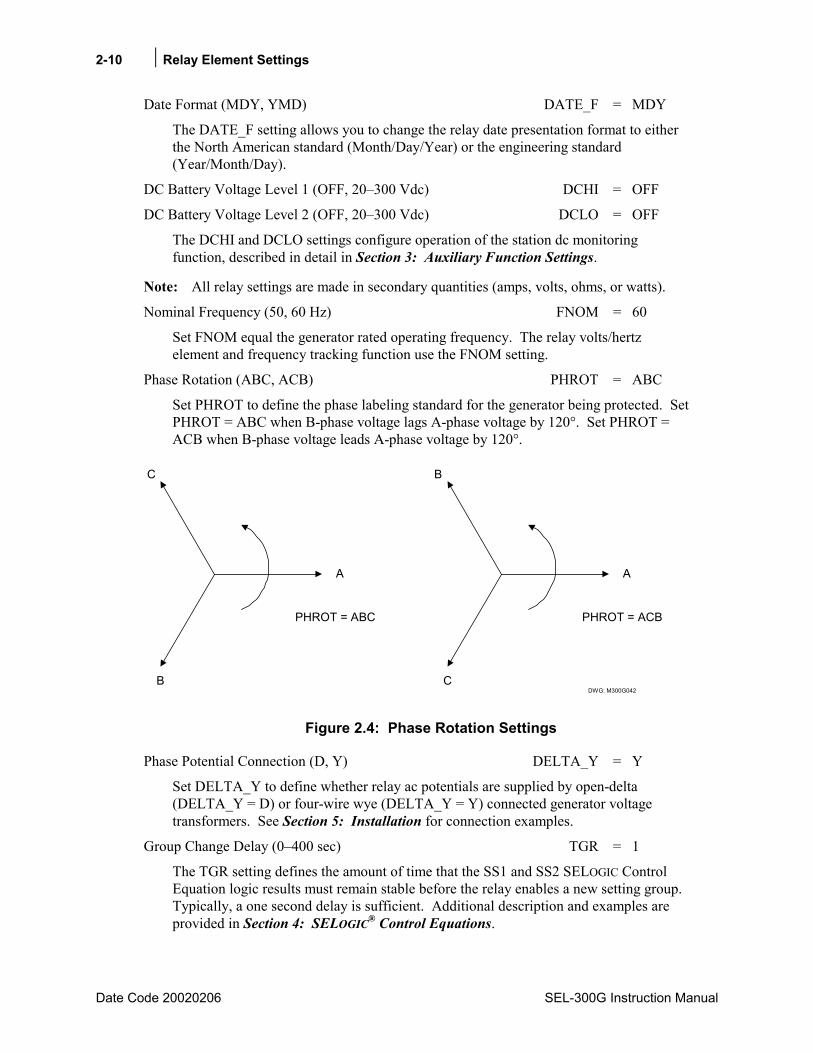
2-10 Relay Element Settings
Date Code 20020206 SEL-300G Instruction Manual
Date Format (MDY, YMD) DATE_F = MDY
The DATE_F setting allows you to change the relay date presentation format to either the North American standard (Month/Day/Year) or the engineering standard (Year/Month/Day).
DC Battery Voltage Level 1 (OFF, 20300 Vdc) DCHI = OFF
DC Battery Voltage Level 2 (OFF, 20300 Vdc) DCLO = OFF
The DCHI and DCLO settings configure operation of the station dc monitoring function, described in detail in Section 3: Auxiliary Function Settings.
Note: All relay settings are made in secondary quantities (amps, volts, ohms, or watts).
Nominal Frequency (50, 60 Hz) FNOM = 60
Set FNOM equal the generator rated operating frequency. The relay volts/hertz element and frequency tracking function use the FNOM setting.
Phase Rotation (ABC, ACB) PHROT = ABC
Set PHROT to define the phase labeling standard for the generator being protected. Set PHROT = ABC when B-phase voltage lags A-phase voltage by 120°. Set PHROT = ACB when B-phase voltage leads A-phase voltage by 120°.
DWG: M300G042
A
C
B
PHROT = ABC
A
B
C
PHROT = ACB
Figure 2.4: Phase Rotation Settings
Phase Potential Connection (D, Y) DELTA_Y = Y
Set DELTA_Y to define whether relay ac potentials are supplied by open-delta (DELTA_Y = D) or four-wire wye (DELTA_Y = Y) connected generator voltage transformers. See Section 5: Installation for connection examples.
Group Change Delay (0400 sec) TGR = 1
The TGR setting defines the amount of time that the SS1 and SS2 SELOGIC Control Equation logic results must remain stable before the relay enables a new setting group. Typically, a one second delay is sufficient. Additional description and examples are provided in Section 4: SELOGIC® Control Equations.

Relay Element Settings 2-11
SEL-300G Instruction Manual Date Code 20020206
Setting Group Selection SS1 = 1 SS2 = 0
SS1 and SS2 are SELOGIC Control Equations that help define when setting Group 1 and setting Group 2 are active. With the settings shown above, SS1 is set equal to logical 1, thus setting Group 1 always is active. Section 3: Auxiliary Function Settings provides additional discussion and examples.
BKR Monitor The settings associated with the breaker monitor function are described in Section 3: Auxiliary Function Settings.
Optioisolated Input Timers Each optoisolated input is equipped with an internal time-delay pickup timer. These timers serve as settable debounce or recognition delay timers. Application and setting selections for these timers is described in Section 3: Auxiliary Function Settings.
Local Bit Settings The relay is equipped with several nondedicated Relay Word bits whose logical condition is controlled by the relay front-panel CONTROL commands. You can use these Relay Word bits to enable or disable protection functions, change tripping logic, close output contacts, etc. Use of this feature is described in Section 4: SELOGIC® Control Equations.
Display Point Settings The relay display point function allows you to display messages, including measured analog quantities, on the relay front-panel LCD. You configure the messages to display the present state of the generator or relay by defining the indicating condition and the message to be displayed when that condition is true and false. Section 4: SELOGIC® Control Equations provides additional descriptions and setting examples.
PHASE MHO DISTANCE ELEMENT
Element Description
Functional Description The SEL-300G Relay provides a two-zone phase mho distance element designed for backup distance protection for system phase-to-phase and three-phase faults. Each zone is equipped with independently settable forward reach, reverse offset, maximum torque angle, step-up transformer compensation, and definite-time delay.
In typical applications, you may wish to set the Zone 1 element to reach into the generator step-up transformer, and with a short time delay, to provide backup protection for low-side

2-12 Relay Element Settings
Date Code 20020206 SEL-300G Instruction Manual
transformer winding and bushing phase-to-phase faults. The Zone 2 element may then be set to reach through the step-up transformer into the system and with a longer time delay.
The relay includes a user settable SELOGIC Control Equation to disable the distance elements, as well as supervision by the 60LOP loss-of-potential logic and a simple load encroachment function to provide three-phase element security under maximum generator loading conditions.
Setting Descriptions Enable System Backup Protection (N, D, V, C) EBUP = D
Set EBUP = D to enable phase distance elements. If system backup protection is not required, set EBUP = N. When EBUP D, the 21P1P, 21P1T, 21P2P, and 21P2T Relay Word bits are inactive and the relay hides the following relay settings, which do not need to be entered. (See Voltage-Controlled/Restrained Time-Overcurrent Elements for EBUP = V and C setting descriptions.)
Zone 1 Phase Distance Reach (OFF, 0.1 to 100.0 ohms) Z1R = 8.0
Zone 1 Phase Distance Offset (0.0 to 10.0 ohms) Z1O = 0.0
Set Z1R to define the forward (toward the system) phase distance reach, defined in secondary ohms. Because the relay includes a load encroachment function for distance element security under heavy load, load impedance is not a concern when selecting the Z1R reach setting. Setting Z1R = OFF disables the element and causes the relay to hide the balance of the settings associated with Zone 1.
The Z1O setting defines the element offset. When an SEL-300G0 or SEL-300G2 Relay is applied with current transformers as shown in Figure 5.16 or Figure 5.17, you may wish to apply a positive offset equal to the generator impedance as backup generator phase-to-phase fault protection.
Zone 1 Maximum Torque Angle (90 to 45 degrees) MTA1 = 88
Set MTA1 equal to the angle of the transformer plus system impedance defined by the Zone 1 reach setting. The relay places the distance element maximum reach along a line at the angle defined by the MTA1 setting.
Zone 1 Transformer Compensation Angle (0, -30, 30 degrees) Z1CMP = 0
Use the Z1CMP setting to compensate the phase distance element for the presence of a delta-wye generator step-up transformer between the generator and system. When the element is not set to reach through the step-up transformer, set Z1CMP = 0. When the element is set to respond to phase faults on the high side of a delta-wye transformer, and the system phase-to-neutral voltage phase angle leads the generator phase-to-neutral voltage phase angle by 30°, set Z1CMP = -30°. When the system phase-to-neutral voltage phase angle lags the generator phase-to-neutral voltage phase angle by 30°, set Z1CMP = 30°.
Zone 1 Phase Distance Time Delay (0.00 to 400.00 s) Z1D = 0.00
The Z1D setting defines the Zone 1 element definite-time delay.
Relay Element Settings 2-13
SEL-300G Instruction Manual Date Code 20020206
Zone 2 Phase Distance Reach (OFF, 0.1 to 100.0 ohms) Z2R = 8.0
Zone 2 Phase Distance Offset (0.0 to 10.0 ohms) Z2O = 0.0
Set Z2R to define the forward (toward the system) phase distance reach, defined in secondary ohms. Because the relay includes a load encroachment function for distance element security under heavy load, load impedance is not a concern when selecting the Z2R reach setting. Setting Z2R = OFF disables the element and causes the relay to hide the balance of the settings associated with Zone 2.
The Z2O setting defines the Zone 2 element offset. When an SEL-300G0 or SEL-300G2 Relay is applied with current transformers as shown in Figure 5.16 or Figure 5.17, you may wish to apply a positive offset equal to the generator impedance as backup generator phase-to-phase fault protection.
Zone 2 Maximum Torque Angle (90 to 45 degrees) MTA2 = 88
Set MTA2 equal to the angle of the transformer plus system impedance defined by the Zone 2 reach setting. The relay places the distance element maximum reach along a line at the angle defined by the MTA2 setting.
Zone 2 Transformer Compensation Angle (0, -30, +30 degrees) Z2CMP = 0
Use the Z2CMP setting to compensate the phase distance element for the presence of a delta-wye generator step-up transformer between the generator and system. When the element is not set to reach through the step-up transformer, set Z2CMP = 0. When the element is set to respond to phase faults on the high side of a delta-wye transformer, and the system phase-neutral voltage phase angle leads the generator phase-to-neutral voltage phase angle by 30°, set Z2CMP = -30°. When the system phase-to-neutral voltage phase angle lags the generator phase-neutral voltage phase angle by 30°, set Z2CMP = 30°.
Zone 2 Phase Distance Time Delay (0.00 to 400.00 s) Z2D = 0.00
The Z2D setting defines the Zone 2 element definite-time delay.
Minimum Power Factor (OFF, 0.98 to 0.50) MPF = 0.80
Maximum Generator Load (0.5 to 3.0 per unit) MXLD = 1.2
The MPF and MXLD settings define the operation of a simple load encroachment function that increases the security of the phase distance elements under heavy load. If load encroachment security is desired, set MPF to the minimum rated generator power factor under maximum load conditions. Set the maximum emergency generator power output in per unit of the generator rating. If load encroachment security is not desired, set MPF = OFF to disable the function.
21P Element Torque Control (SELOGIC Control Equation) 21PTC = !3PO
The phase distance elements are enabled when the result of 21PTC equals logical 1. The elements are blocked when the 21PTC SELOGIC Control Equation result equals logical 0. Typically, the 21PTC SELOGIC Control Equation should be set so the elements are enabled when the generator main circuit breaker is closed (!3PO). Other supervisory conditions may be added if your application requires.
Note: Loss-of-potential (60LOP) supervision is built into the element logic so it does not need to be added to the 21PTC SELOGIC Control Equation setting.

2-14 Relay Element Settings
Date Code 20020206 SEL-300G Instruction Manual
Relay Word Bits
Relay Word Bit Function Description Typical Applications
21P1P Instantaneous Zone 1 Phase Distance Element Pickup
Indication, Testing, SER, Event Triggering
21P1T Time-Delayed Zone 1 Phase Distance Element Pickup
Indication, Testing, Tripping
21P2P Instantaneous Zone 2 Phase Distance Element Pickup
Indication, Testing, SER, Event Triggering
21P2T Time-Delayed Zone 2 Phase Distance Element Pickup
Indication, Testing, Tripping
Setting Calculation
Information Needed
• Zone 1 and Zone 2 reach apparent impedance magnitude and angle.
• Generator Step-Up Transformer Connection (only required if Zone 1 or Zone 2 is set to reach through the transformer).
• Zone 1 and Zone 2 coordination time delay.
• Generator Rated Minimum Power Factor and Maximum Emergency Loading.
Recommendations The phase distance elements provide backup phase fault protection for the generator, step-up transformer, and system. Zone 2 is typically set to reach far out onto the system. Usually, a fault study is necessary to determine the magnitude and angle of the apparent impedance seen by the generator relay during a system fault. When ZnCMP = 0, use the apparent positive-sequence impedance seen by the relay during a three-phase fault. When ZnCMP = +30 or -30, set ZnR equal to three times the apparent positive-sequence impedance calculated by fault study for a three-phase fault at the desired reach limit point on the system. The three-times factor compensates for the effect of the delta-wye power transformer on the apparent impedance presented to the relay. All distance element reaches and offsets are set in secondary ohms.
After determining the minimum reach setting required to obtain desired sensitivity with all system breakers closed, you may wish to determine the element sensitivity when one or more local bus circuit breakers are open. This operating contingency review shows with which relays the Zone 2 element time delay must coordinate.
Zone 1 is usually set shorter than Zone 2, with a corresponding shorter time delay.
The distance element offset required for each zone depends on the location of the relay current transformers. If current transformers are connected near the generator neutral, as in Figure 5.13 and Figure 5.14, set the distance element offsets to 0.1 ohms. If current transformers are connected as in Figure 5.16 and Figure 5.17, a nonzero offset can provide some backup phase fault protection for the generator. Offsets for Zone 1 and Zone 2 should be set equal, unless
Relay Element Settings 2-15
SEL-300G Instruction Manual Date Code 20020206
some special performance characteristic is desired. Offset impedance equal to the generator Xd' is reasonable when ZnCMP = 0. Use 3 · Xd' when ZnCMP = +30 or -30.
The transformer compensation settings, Z1CMP and Z2CMP, instruct the relay to compensate the distance elements for the influence of the delta-wye connected generator step-up transformer. When an element is not set to reach through the step-up transformer, set ZnCMP = 0, where n = 1 or 2. When the element is set to respond to phase faults on the high side of a delta-wye transformer and the system phase-to-neutral voltage phase angle leads the generator phase-to-neutral voltage phase angle by 30°, set ZnCMP = -30°. When the system phase-to-neutral voltage phase angle lags the generator phase-to-neutral voltage phase angle by 30°, set ZnCMP = 30°.
In order to obtain desired sensitivity, it may be necessary to set the Zone 1 and/or Zone 2 element reach very long. Due to the long reach setting, many phase distance relays would pick up during heavy load. The SEL-300G Relay distance elements are supervised by a simple load encroachment function (when enabled) that prevents distance element misoperation under heavy load. To enable load encroachment supervision, set MPF equal to the generator minimum power factor and MXLD to the maximum emergency load rating of the generator in per unit of continuous rating. The relay uses these two settings to define a region in the impedance plane where operation of the three-phase elements is prevented. This allows you to make phase distance element reach settings without concern for misoperation under heavy generator load.
Phase Distance Tripping Because the phase distance elements detect system faults of an enduring and potentially serious nature, tripping generally is applied to the generator main breaker, the field breaker, the prime mover, and the generator lockout relay. Refer to Section 4: SELOGIC® Control Equations for more detail and examples of tripping SELOGIC Control Equations.
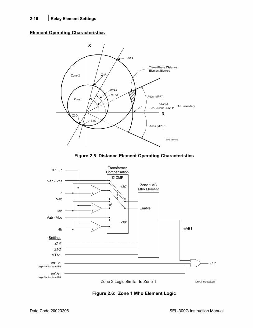
2-16 Relay Element Settings
Date Code 20020206 SEL-300G Instruction Manual
Element Operating Characteristics
DWG: M300G212
Zone 2 Z1R
Z2R
MTA2MTA1
Z1O
Z2O
VNOM3 INOM MXLD
Secondary
Acos (MPF)°
-Acos (MPF)°
Three-Phase DistanceElement Blocked
Zone 1
R
X
Figure 2.5 Distance Element Operating Characteristics
Z1P
Vab - Vca
Z1R
Z1O
Settings
+
_
0.1 In
Ia
Vab
+
_
Iab
Vab - Vbc
-Ib
TransformerCompensation
Z1CMP
0°
-30°
Zone 1 ABMho Element
Enable
mAB1
mBC1Logic Similar to mAB1
mCA1Logic Similar to mAB1
Zone 2 Logic Similar to Zone 1
MTA1
DWG: M300G230
+30°
+
_
Figure 2.6: Zone 1 Mho Element Logic

Relay Element Settings 2-17
SEL-300G Instruction Manual Date Code 20020206
RelayWord
Bits
60LOP21PTC
|ang(Z1)|
Acos(MPF)
|Z1| +_
+_
MPF = OFF
Z2P
Z1PZ1D
0
21P2T
21P2P
21P1T
21P1PFrom above:
DWG: M300G231
RelayWordBits
Z2D
0
VNOMMXLD(INOM1.732)
0.125 +_|I2|
|I1|
Figure 2.7: Phase Distance Element Logic
VOLTS/HERTZ ELEMENT
Element Description
Functional Description Overexcitation occurs when a generator or transformer magnetic core becomes saturated. When this happens, stray flux is induced in nonlaminated components, causing overheating. In the SEL-300G Relay, overexcitation is detected by a volts/hertz element. The SEL-300G Relay provides a sensitive definite-time volts/hertz element, plus a tripping element with a composite operating time. The relay calculates the present machine volts/hertz as a percent of nominal, based on the present and nominal voltages and frequencies. The settings VNOM and FNOM define the nominal machine voltage and frequency, respectively.
Figure 2.13 shows the volts/hertz element logic. If the 24TC SELOGIC Control Equation is true and the present volts/hertz exceed the 24D1P setting, the relay asserts the 24D1 Relay Word bit and starts the 24P1D timer. If the condition remains for 24P1D seconds, the relay asserts the 24D1T Relay Word bit. Typically, you should apply this element as an overexcitation alarm.
For volts/hertz tripping, the relay provides a time-integrating element with a settable operating characteristic. You can set the element to operate as an inverse-time element, a composite element with an inverse-time characteristic and a definite-time characteristic, or as a dual-level, definite-time element. In any case, the element provides a linear reset characteristic with a settable reset time. This element also is supervised by the 24TC torque-control setting.

2-18 Relay Element Settings
Date Code 20020206 SEL-300G Instruction Manual
The volts/hertz tripping element has a percent-travel operating characteristic similar to that employed by an induction-disk time-overcurrent element. This characteristic coincides well with the heating effect that overexcitation has on the generator components.
Setting Descriptions Enable Volts/Hertz Protection (Y, N) E24 = Y
Set E24 = Y to enable volts/hertz protection elements. If volts/hertz protection is not required, set E24 = N. When E24 = N, the 24TC, 24D1, 24D1T, 24C2, 24C2T, and 24CR Relay Word bits are inactive and the following relay settings are hidden and do not need to be entered.
Level 1 Volts/Hertz Pickup (100200%) 24D1P = 105
Level 1 Time Delay (0.00400.00 s) 24D1D = 1.00
The Level 1 element should be applied as an overexcitation alarm. The 24D1P setting defines the percent volts/hertz alarm pickup. The 24D1 Relay Word bit asserts without time delay when the measured machine volts/hertz exceed the 24D1P setting. The 24D1T Relay Word bit asserts 24D1D seconds after 24D1 asserts if the measured volts/hertz remain above the 24D1P setting.
Level 2 Composite Curve Shape (OFF, DD, ID, I) 24CCS = DD
The 24CCS setting defines the overexcitation tripping element time-delay characteristic or disables the element when set equal to OFF. Set 24CCS = OFF if you do not require Level 2 volts/hertz protection. When 24CCS = OFF, the other Level 2 settings are hidden and do not need to be entered.
When 24CCS = DD:
The element operates with a dual-level, definite-time characteristic, illustrated in Figure 2.8.
Level 2 Pickup One (100200%) 24D2P1 = 110
Level 2 Time-Delay One (0.00400.00 s) 24D2D1 = 60.00
Level 2 Pickup Two (100200%) 24D2P2 = 118
Level 2 Time-Delay Two (0.00400.00 s) 24D2D2 = 6.00
The SEL-300G Relay asserts the 24C2 Relay Word bit without time delay when the machine volts/hertz exceed either the 24D2P1 or 24D2P2 setting. If the volts/hertz percentage is greater than the 24D2P1 setting, but less than the 24D2P2 setting, the relay asserts the 24C2T Relay Word bit in 24D2D1 seconds. When the volts/hertz percentage is greater than the 24D2P2 setting, the relay asserts the 24C2T Relay Word bit in 24D2D2 seconds. 24D2P1 must be set less than 24D2P2.

Relay Element Settings 2-19
SEL-300G Instruction Manual Date Code 20020206
When 24CCS = ID:
The element operates with a composite inverse/definite-time characteristic illustrated in Figure 2.9.
Level 2 Inverse-Time Pickup (100200%) 24IP = 105
Level 2 Inverse-Time Curve (0.5, 1.0, 2.0) 24IC = 2
Level 2 Inverse-Time Factor (0.1010.0 s) 24ITD = 0.100
Level 2 Pickup Two (100200%) 24D2P2 = 175
Level 2 Time-Delay Two (0.00400.00 s) 24D2D2 = 0.1
The 24IP setting defines the pickup point of the inverse-time portion of the operating time curve. The SEL-300G Relay asserts the 24C2 Relay Word bit without time delay when the machine volts/hertz exceed the 24IP setting. The 24IC setting defines the element operating time curve shape. The 24ITD setting defines the inverse element operate time in seconds when the machine volts/hertz equals 200%. The 24D2P2 and 24D2D2 settings define the pickup and definite operating time of the definite-time portion of the composite curve. The relay asserts the 24C2T Relay Word bit in time defined by the inverse curve when the measured volts/hertz are less than the 24D2P2 setting. The relay asserts the 24C2T Relay Word bit in time defined by the 24D2D2 definite-time settings when the measured volts/hertz are greater than the 24D2P2 setting. 24IP must be set less than 24D2P2.
When 24CCS = I:
The element operates with a simple inverse-time characteristic illustrated in Figure 2.10, Figure 2.11, or Figure 2.12, depending on the 24IC setting.
Level 2 Inverse-Time Pickup (100200%) 24IP = 105
Level 2 Inverse-Time Curve (0.5, 1.0, 2.0) 24IC = 2
Level 2 Inverse-Time Factor (0.1010.0 s) 24ITD = 0.1
The 24IP setting defines the pickup point of the inverse-time portion of the operating time curve. The SEL-300G Relay asserts the 24C2 Relay Word bit without time delay when the machine volts/hertz exceed the 24IP setting. The 24IC setting defines the curve shape. The 24ITD setting defines the inverse element operate time in seconds when the machine volts/hertz equal 200%. The relay asserts the 24C2T Relay Word bit in time defined by the inverse curve when the machine volts/hertz exceed the 24IP setting.
When 24CCS = DD, ID, or I:
Level 2 Reset Time (0.00400.00 s) 24CR = 240.00
The 24CR setting defines the composite element reset time. When the element times out to trip, it will fully reset 24CR seconds after the applied volts/hertz drop below the element pickup setting. The element reset characteristic is linear, so if the element times 60% toward a trip, it will fully reset (0.6 24CR) seconds after the applied volts/hertz drop below the element pickup setting. When the element is reset, the relay asserts the 24CR Relay Word bit.
2-20 Relay Element Settings
Date Code 20020206 SEL-300G Instruction Manual
24 Element Torque Control (SELOGIC Control Equation) 24TC = !60LOP
Both volts/hertz elements are disabled when the 24TC SELOGIC Control Equation equals logical 0. The elements are allowed to operate when the 24TC SELOGIC Control Equation equals logical 1. Typically, the 24TC SELOGIC Control Equation should be set so the volts/hertz elements is allowed to operate when there is no loss-of-potential (60LOP) condition detected. Other supervisory conditions may be added if your application requires.
Relay Word Bits
Relay Word Bit Function Description Typical Applications
24D1 Level 1Volts/Hertz Instantaneous Pickup Indication, Event Triggering, SER Triggering, Testing
24D1T Level 1Volts/Hertz With Definite-Time Delay
Indication, Event Triggering, SER Triggering
24C2 Level 2Volts/Hertz Pickup Indication, Event Triggering, SER Triggering, Testing
24C2T Level 2 Volts/Hertz Trip Tripping, SER Triggering
24CR Level 2 Volts/Hertz Reset Testing
Setting Calculation
Information Needed
• Generator Manufacturers Overexcitation Limit Curve
• Step-up Transformer Manufacturers Overexcitation Limit Curve on Generator Voltage Base (if transformer overexcitation protection is desired)
Recommendations Use the Level 1 volts/hertz element as an overexcitation alarm. Set 24D1P equal to or greater than 105%, but less than the minimum pickup of the Level 2 element. Use a 24D1D time delay of 1.0 second to allow time for manual correction of an overexcitation condition prior to a trip.
Use the Level 2 volts/hertz element as an overexcitation tripping element. Select the dual level, composite inverse, or simple inverse operating time characteristic to conform with the generator manufacturers recommendations.
Volts/Hertz Tripping Volts/Hertz tripping elements are usually used to trip the main generator breaker and the field breaker and transfer auxiliaries, if needed. Refer to Section 4: SELOGIC® Control Equations for more detail and examples of tripping SELOGIC Control Equations.

Relay Element Settings 2-21
SEL-300G Instruction Manual Date Code 20020206
Element Operating Characteristics
Figure 2.8 and Figure 2.9 are similar to IEEE C37.102: 1987 IEEE Guide for AC Generator Protection Figure 4.5.4-1 and Figure 4.5.4-2.
.01 0.1 1.0 10 100 1000
100
110
120
130
140
24D2P2=118%24D2D2=6 s
24D2P1=110%24D2D1=60 s
Time (Minutes)
Transformer Limit Curveon Gen. Voltage Base
Mfg-GeneratorLimit Curve
Volts
/Her
tz (
%)
DWG: M300G043
Figure 2.8: Dual-Level Volts/Hertz Time-Delay Characteristic, 24CCS=DD
Relay Characteristic
Time (Minutes)
Generator Manufacturer'sRecommended Protection Curve
Transformer Limit Curve onGenerator Voltage Base
DWG: M300G044
.001 .01 0.1 1.0 10 100
100
110
120
130
140
Volts
/Her
tz (
%)
1000
24D2P2=118%24D2D2=1.2 s
24IP=108%
Figure 2.9: Composite Inverse/Definite-Time Overexcitation Characteristic, 24CCS=ID

2-22 Relay Element Settings
Date Code 20020206 SEL-300G Instruction Manual
1000.01
0.1
1
10
100
120 140 160 180 200
24C
2T O
pera
ting
Tim
e(s
econ
ds)
Volts/Hertz (%)(24IP = 100%)
24ITD = 5.0 24ITD = 7.524ITD = 10.0
24ITD = 0.524ITD = 1.0
24ITD = 0.1
DWG: M300G147
5.0PP
p
1
%100IP24
VNOMFNOM
freqV
ITD24t
−
= seconds
Figure 2.10: Volts/Hertz Inverse-Time Characteristic, 24IC = 0.5

Relay Element Settings 2-23
SEL-300G Instruction Manual Date Code 20020206
1000.01
0.1
1
10
100
1000
24ITD = 5.0
120 140 160 180 200
24ITD = 7.524ITD = 10.0
24ITD = 0.524ITD = 1.0
24ITD = 0.124C
2T O
pera
ting
Tim
e(s
econ
ds)
Volts/Hertz (%)(24IP = 100%)
DWG: M300G148
1PP
p
1
100%24IP
VNOMFNOM
freqV
24ITDt
−
= seconds
Figure 2.11: Volts/Hertz Inverse-Time Characteristic, 24IC = 1

2-24 Relay Element Settings
Date Code 20020206 SEL-300G Instruction Manual
0.01
0.1
1
10
100
1000
10000
100 120 140 160 180 200
24C
2T O
pera
ting
Tim
e(s
econ
ds)
Volts/Hertz (%)(24IP = 100%)
24ITD = 5.0
24ITD = 7.5
24ITD = 10.0
24ITD = 0.524ITD = 1.0
24ITD = 0.1
DWG: M300G149
2PP
p
1
100%24IP
VNOMFNOM
freqV
24ITDt
−
= seconds
Figure 2.12: Volts/Hertz Inverse-Time Characteristics, 24IC = 2
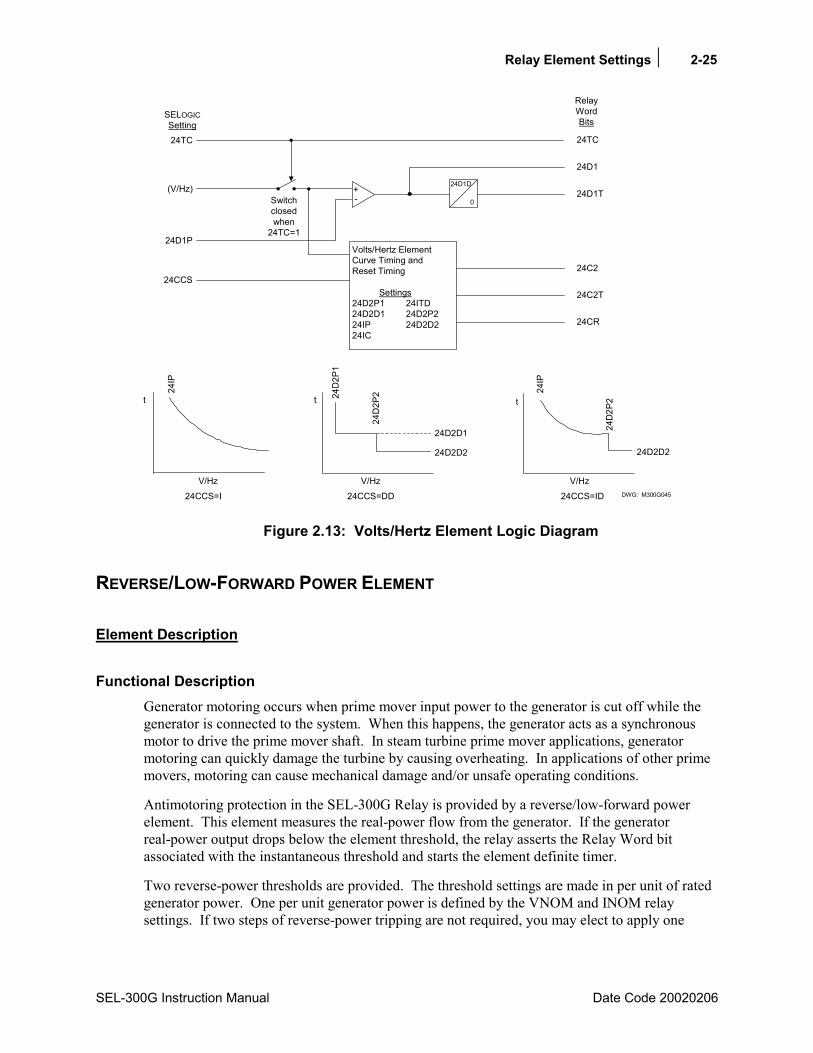
Relay Element Settings 2-25
SEL-300G Instruction Manual Date Code 20020206
DWG: M300G045
+-
24D1D
0
Volts/Hertz ElementCurve Timing andReset Timing
Settings24D2P1 24ITD24D2D1 24D2P224IP 24D2D224IC
24D1
24D1T
24C2
24C2T
24CR
(V/Hz)
t
V/Hz
24D
2P1
24D
2P224
IP
24D2D2
24CCS=DD
24IP
24D
2P2t
V/Hz24CCS=ID
RelayWordBits
24TC
Switchclosedwhen
24TC=1
24D2D2
24CCS
V/Hz
t
24CCS=I
24D2D1
24TC
SELOGICSetting
24D1P
Figure 2.13: Volts/Hertz Element Logic Diagram
REVERSE/LOW-FORWARD POWER ELEMENT
Element Description
Functional Description Generator motoring occurs when prime mover input power to the generator is cut off while the generator is connected to the system. When this happens, the generator acts as a synchronous motor to drive the prime mover shaft. In steam turbine prime mover applications, generator motoring can quickly damage the turbine by causing overheating. In applications of other prime movers, motoring can cause mechanical damage and/or unsafe operating conditions.
Antimotoring protection in the SEL-300G Relay is provided by a reverse/low-forward power element. This element measures the real-power flow from the generator. If the generator real-power output drops below the element threshold, the relay asserts the Relay Word bit associated with the instantaneous threshold and starts the element definite timer.
Two reverse-power thresholds are provided. The threshold settings are made in per unit of rated generator power. One per unit generator power is defined by the VNOM and INOM relay settings. If two steps of reverse-power tripping are not required, you may elect to apply one

2-26 Relay Element Settings
Date Code 20020206 SEL-300G Instruction Manual
threshold as a tripping interlock for sequential generator tripping. The element setting ranges are broad enough to permit application of a threshold as a generator overload element.
The reverse/low-forward power element is supervised by the 32TC torque-control setting.
Setting Descriptions Enable Reverse/Low-Forward Power Protection (Y, N) E32 = Y
Set E32 = Y to enable reverse/low-forward power protection elements. If reverse/low-forward power protection is not required, set E32 = N. When E32 = N, the 32PTC, 32P1, 32P1T, 32P2, and 32P2T Relay Word bits are inactive and the following relay settings are hidden and do not need to be entered.
Level 1 Power Threshold (0.0015 to 3.0000 pu ) 32P1P = -0.0500
Level 1 Power Time Delay (0.01400.00 s) 32P1D = 20.00
The Level 1 element should be applied as a tripping function. The 32P1P setting defines the per unit power threshold. With the example setting above, the 32P1 Relay Word bit asserts without time delay when the measured power exceeds 0.05 per unit into the machine. The 32P1T Relay Word bit asserts 32P1D seconds after 32P1 asserts. One per unit power is defined by the VNOM and INOM settings.
Level 2 Power Threshold (OFF, 0.0015 to 3.0000 pu) 32P2P = 0.0200
Level 2 Power Time Delay (0.01400.00 s) 32P2D = 1.00
The Level 2 element may be applied as a sequential tripping interlock or as an overload function. The 32P2P defines the per unit power threshold. As set above, the 32P2 Relay Word bit asserts without time delay when the measured power falls below 0.02 per unit out of the machine. The 32P2T Relay Word bit asserts 32P2D seconds after 32P2 asserts. One per unit power is defined by the VNOM and INOM settings. Set 32P2P = OFF to disable the second threshold and hide the 32P2D setting.
32 Element Torque Control (SELOGIC Control Equation) 32TC = !60LOP
The reverse/low-forward power elements are disabled when the 32TC SELOGIC Control Equation equals logical 0. The elements are allowed to operate when the 32TC SELOGIC Control Equation equals logical 1. With the example setting, the reverse power function is allowed to operate when there is no loss-of-potential condition detected. You may wish to torque control this function with the !3PO condition to disable the reverse power elements when the generator breaker is open.
Relay Element Settings 2-27
SEL-300G Instruction Manual Date Code 20020206
Relay Word Bits
Relay Word Bit Function Description Typical Applications
32P1 Level 1 Reverse/Low-Forward Power Pickup Indication, Event Triggering, SER Triggering, Testing
32P1T Level 1 Reverse/Low-Forward Power Pickup With Definite-Time Delay
Tripping, SER Triggering, Pickup Definite-Time Delay
32P2 Level 2 Reverse/Low-Forward Power Pickup Indication, Event Triggering, SER Triggering, Testing
32P2T Level 2 Reverse/Low-Forward Power Pickup With Definite-Time Delay
Tripping, SER Triggering, Pickup Definite-Time Delay
Setting Calculation
Information Needed
• Prime Mover Manufacturers Rated Motoring Power and Motoring Withstand Time Limit
• Generator Rated Power
Recommendations Calculate the prime mover rated motoring power in per unit of generator rated power by dividing motoring power by the generator rating.
PowerRatedGeneratorPowerMotoringRatedPowerMotoringUnitPer −
=
Motoring power is negative by definition, since it is flowing into rather than out of the generator.
To ensure that the element securely detects this level of power, the element setting should be adjusted to account for measuring errors in the relay, voltage transformers, and current transformers. A 0.7 to 0.5 multiplier will provide secure detection of motoring conditions as low as 0.02 per unit, suggesting a 32P1P setting of 0.014 to 0.01 per unit. Relay measuring error for the power element is specified as ±0.0015 per unit, ±2% of setting.
32P1P = (0.7 to 0.5) (Per Unit Motor Power) per unit
Use a 32P1D time delay of 20.0 to 30.0 seconds or as recommended by the prime mover manufacturer. This delay prevents reverse-power tripping during machine paralleling operations.
Use the Level 2 reverse/low-forward power element as a sequential tripping interlock or an overload element.
When the Level 2 element is applied as a sequential tripping interlock, the 32P2P setting should be set using a low-forward power value, 5 to 10% of machine rating. The element only should be permitted to cause a generator breaker trip after the prime mover trip has occurred. The SELOGIC Control Equations used to implement sequential generator tripping are described in Section 4: SELOGIC® Control Equations of this instruction manual.
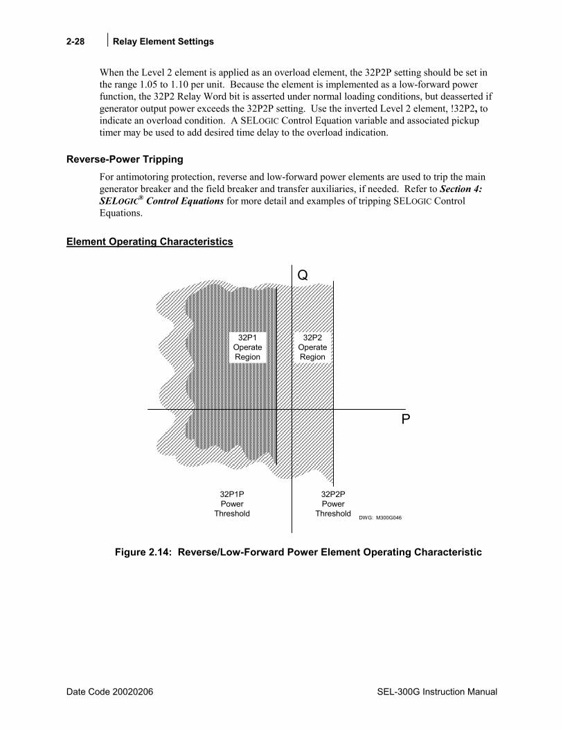
2-28 Relay Element Settings
Date Code 20020206 SEL-300G Instruction Manual
When the Level 2 element is applied as an overload element, the 32P2P setting should be set in the range 1.05 to 1.10 per unit. Because the element is implemented as a low-forward power function, the 32P2 Relay Word bit is asserted under normal loading conditions, but deasserted if generator output power exceeds the 32P2P setting. Use the inverted Level 2 element, !32P2, to indicate an overload condition. A SELOGIC Control Equation variable and associated pickup timer may be used to add desired time delay to the overload indication.
Reverse-Power Tripping For antimotoring protection, reverse and low-forward power elements are used to trip the main generator breaker and the field breaker and transfer auxiliaries, if needed. Refer to Section 4: SELOGIC® Control Equations for more detail and examples of tripping SELOGIC Control Equations.
Element Operating Characteristics
DWG: M300G046
Q
P
32P1OperateRegion
32P1PPower
Threshold
32P2PPower
Threshold
32P2OperateRegion
Figure 2.14: Reverse/Low-Forward Power Element Operating Characteristic

Relay Element Settings 2-29
SEL-300G Instruction Manual Date Code 20020206
32P1D
0
32P2D
032P2T
Switches Closed when32TC = Logical 1
DWG: M300G056
32P2
32P1T
32P1
32P2P
32P1P
MeasuredReal Power
32TC
SELOGICSettings
Settings
RelayWordBits
Figure 2.15: Reverse/Low-Forward Power Element Logic Diagram
LOSS-OF-FIELD ELEMENT
Element Description
Functional Description Loss-of-field current causes the synchronous generator to act as an induction generator. The rotor speed increases, active power output decreases, and the generator pulls vars from system. High currents are induced in the rotor and stator current as high as 2.0 per unit is possible. These high currents cause dangerous overheating in a very short time.
The SEL-300G Relay detects loss-of-field using a pair of offset mho circles. Since loss-of-field affects all three phases, the condition is a balanced one. The SEL-300G Relay uses measured positive-sequence impedance to form the mho circles.
Typically, Zone 1 and Zone 2 are offset from the impedance plane origin by a value equal to one-half the machine transient reactance. Zone 1 is intended to operate with little time delay in the event of a loss-of-field under full load conditions. Zone 2 reaches further and operates with a longer time delay. Zone 2 is intended to trip for loss-of-field conditions that occur under light load conditions.
For compatibility with some existing electromechanical loss-of-field relays, the SEL-300G Relay Zone 2 element may be set with a positive offset equal to the generator step-up transformer reactance. When Zone 2 is used in this manner, the relay provides a directional element with a settable angle characteristic. The Zone 2 element would be used together with an undervoltage element to provide faster tripping if system voltage is depressed during the loss-of-field condition.
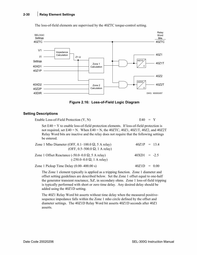
2-30 Relay Element Settings
Date Code 20020206 SEL-300G Instruction Manual
The loss-of-field elements are supervised by the 40ZTC torque-control setting.
40Z1D
0
40Z2D
040Z2T
DWG: M300G057
40Z2
40Z1T
40Z1
40XD2
40Z1P
Zone 2Calculation
Zone 1Calculation
ImpedanceCalculation
40XD1
40Z2P40DIR
I1
V1
40ZTC
SELOGICSettings
Z1 Settings
40ZTC
RelayWordBits
Figure 2.16: Loss-of-Field Logic Diagram
Setting Descriptions Enable Loss-of-Field Protection (Y, N) E40 = Y
Set E40 = Y to enable loss-of-field protection elements. If loss-of-field protection is not required, set E40 = N. When E40 = N, the 40ZTC, 40Z1, 40Z1T, 40Z2, and 40Z2T Relay Word bits are inactive and the relay does not require that the following settings be entered.
Zone 1 Mho Diameter (OFF, 0.1100.0 , 5 A relay) 40Z1P = 13.4 (OFF, 0.5500.0 , 1 A relay)
Zone 1 Offset Reactance (-50.00.0 , 5 A relay) 40XD1 = -2.5 (-250.00.0 , 1 A relay)
Zone 1 Pickup Time Delay (0.00400.00 s) 40Z1D = 0.00
The Zone 1 element typically is applied as a tripping function. Zone 1 diameter and offset setting guidelines are described below. Set the Zone 1 offset equal to one-half the generator transient reactance, Xd', in secondary ohms. Zone 1 loss-of-field tripping is typically performed with short or zero time delay. Any desired delay should be added using the 40Z1D setting.
The 40Z1 Relay Word bit asserts without time delay when the measured positive-sequence impedance falls within the Zone 1 mho circle defined by the offset and diameter settings. The 40Z1D Relay Word bit asserts 40Z1D seconds after 40Z1 asserts.

Relay Element Settings 2-31
SEL-300G Instruction Manual Date Code 20020206
Zone 2 Mho Diameter (OFF, 0.1100.0 , 5 A relay) 40Z2P = 13.4 (OFF, 0.5500.0 , 1 A relay)
Zone 2 Offset Reactance (-50.050.0 , 5 A relay) 40XD2 = -2.5 (-250.0250.0 , 1 A relay)
Zone 2 Pickup Time Delay (0.00400.00 s) 40Z2D = 0.50
Zone 2 Directional Superv. Angle (-20.00.0) 40DIR = -10.0
The Zone 2 element typically is applied as a time-delayed tripping function. Zone 2 diameter and offset setting guidelines are described below.
Zone 2 loss-of-field tripping typically is performed with 0.5 to 0.6 second time delay. Set 40Z2D equal to the desired delay.
The 40DIR setting is hidden when 40XD2 < 0.
The 40Z2 Relay Word bit asserts without time delay when the measured positive sequence impedance falls within the Zone 2 mho circle defined by the offset and diameter settings, and below the directional supervision line, if used. The 40Z2T Relay Word bit asserts 40Z2D seconds after 40Z2 asserts.
40Z Element Torque Control (SELOGIC Control Equation): 40ZTC = !60LOP
The loss-of-field elements are disabled when the 40ZTC SELOGIC Control Equation equals logical 0. The elements are allowed to operate when the 40ZTC SELOGIC Control Equation equals logical 1. With the example setting, the loss-of-field elements are allowed to operate when there is no loss-of-potential condition detected.
Note: The loss-of-field elements require at least 0.25 volts of positive-sequence voltage and 0.25 amps of positive-sequence current to operate.
Relay Word Bits
Relay Word Bit Function Description Typical Applications
40Z1 Zone 1 Loss-of-Field Pickup Indication, Event Triggering, SER Triggering, Testing
40Z1T Zone 1 Loss-of-Field Pickup With Definite-Time Delay
Tripping, SER Triggering
40Z2 Zone 2 Loss-of-Field Pickup Indication, Event Triggering, SER Triggering, Testing
40Z2T Zone 2 Loss-of-Field Pickup With Definite-Time Delay
Tripping, SER Triggering
2-32 Relay Element Settings
Date Code 20020206 SEL-300G Instruction Manual
Setting Calculation
Information Needed
• Generator direct axis reactance, Xd, in secondary ohms
• Generator transient reactance, Xd', in secondary ohms
• Generator rated line-to-line voltage, in secondary volts (VNOM setting)
• Generator rated phase current, in secondary amps (INOM setting)
• When a positive Zone 2 offset is desired, you also need:
• Step-up transformer reactance, XT, in secondary ohms
• Generator rated power factor
Recommendations Unless there is a requirement to match existing loss-of-field protection that uses a positive offset Zone 2 element, use the negative offset setting recommendations below. Recommendations for both setting methods are provided.
Loss-of-Field Protection Using a Negative Offset Zone 2
When setting Zone 2 with a negative offset, set the Zone 1 diameter equal to 1.0 per unit impedance.
ΩINOM1.73
VNOM40Z1P =
Set the Zone 1 offset equal to one-half the generator transient reactance, Xd', in secondary ohms.
Ω−
=2
'Xd1XD40
Zone 1 loss-of-field tripping is typically performed with short or zero time delay.
seconds 0.040Z1D =
Set the Zone 2 diameter equal to the machine direct axis reactance, Xd, in secondary ohms.
Ω Xd40Z2P =
Set the Zone 2 offset equal the Zone 1 offset.
Ω−
=2
'Xd2XD40

Relay Element Settings 2-33
SEL-300G Instruction Manual Date Code 20020206
Set the Zone 2 time delay equal to 0.5 to 0.6 seconds or according to the generator manufacturers recommendations.
seconds 0.540Z2D =
In this case, the 40DIR setting is hidden.
Loss-of-field protection typically trips the main generator breaker and the field breaker. When applying loss-of-field protection with a negative Zone 2 offset, you can use the time-delay Zone 1 and Zone 2 Relay Word bits, 40Z1T and 40Z2T, directly in the generator breaker and field breaker tripping SELOGIC Control Equations. See Section 4: SELOGIC® Control Equations of this instruction manual for more details and an example.
Loss-of-Field Protection Using a Positive Offset Zone 2
When setting Zone 2 with a positive offset, set the Zone 1 diameter:
Ω2Xd'Xd1.140Z1P −+=
Set the Zone 1 offset equal to one-half the generator transient reactance, Xd', in secondary ohms.
Ω−=2
'Xd1XD40
Traditionally, the Zone 1 delay for this type of scheme is 0.25 seconds.
second 0.2540Z1D =
Set the Zone 2 diameter using the direct axis reactance and the step-up transformer reactance.
Ω XTXd1.140Z2P +=
Set the Zone 2 offset using the reactance of the generator step-up transformer, XT.
Ω XT40XD2 =
Traditionally, the Zone 2 delay for this type of scheme is 1 second.
second 1.040Z2D =
A shorter delay traditionally is applied if the Zone 2 element picks up at the same time that an undervoltage condition is detected. This logic is discussed below.
In this case, the 40DIR setting is required. Set 40DIR equal to 20° or the arccosine of the minimum rated power factor, whichever is smaller.
When applying loss-of-field protection with a positive Zone 2 offset, you can use the time-delayed Zone 1 Relay Word bit, 40Z1T, and the long-time-delayed Zone 2 Relay Word bit, 40Z1T, directly in the generator breaker and field breaker tripping SELOGIC Control Equations.
The traditional application of this scheme provides accelerated (0.25 second) Zone 2 tripping in the event of an undervoltage condition occurring during the loss-of-field. To achieve this accelerated tripping, it is necessary to use a SELOGIC Control Equation variable and a positive-
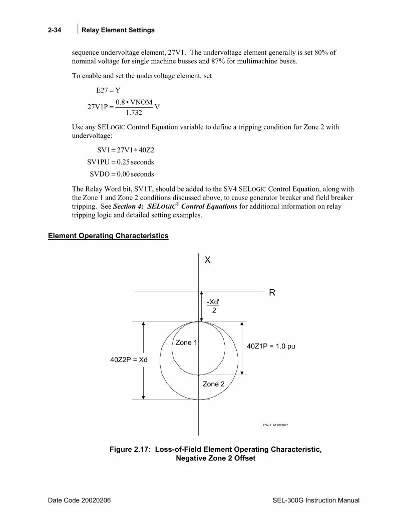
2-34 Relay Element Settings
Date Code 20020206 SEL-300G Instruction Manual
sequence undervoltage element, 27V1. The undervoltage element generally is set 80% of nominal voltage for single machine busses and 87% for multimachine buses.
To enable and set the undervoltage element, set
V1.732
VNOM0.827V1P
YE27
=
=
Use any SELOGIC Control Equation variable to define a tripping condition for Zone 2 with undervoltage:
seconds 0.00SVDOseconds 0.25SV1PU
40Z227V1SV1
=
=
∗=
The Relay Word bit, SV1T, should be added to the SV4 SELOGIC Control Equation, along with the Zone 1 and Zone 2 conditions discussed above, to cause generator breaker and field breaker tripping. See Section 4: SELOGIC® Control Equations for additional information on relay tripping logic and detailed setting examples.
Element Operating Characteristics
40Z1P = 1.0 pu
-Xd' 2
X
R
DWG: M300G047
Zone 1
Zone 2
40Z2P = Xd
Figure 2.17: Loss-of-Field Element Operating Characteristic, Negative Zone 2 Offset
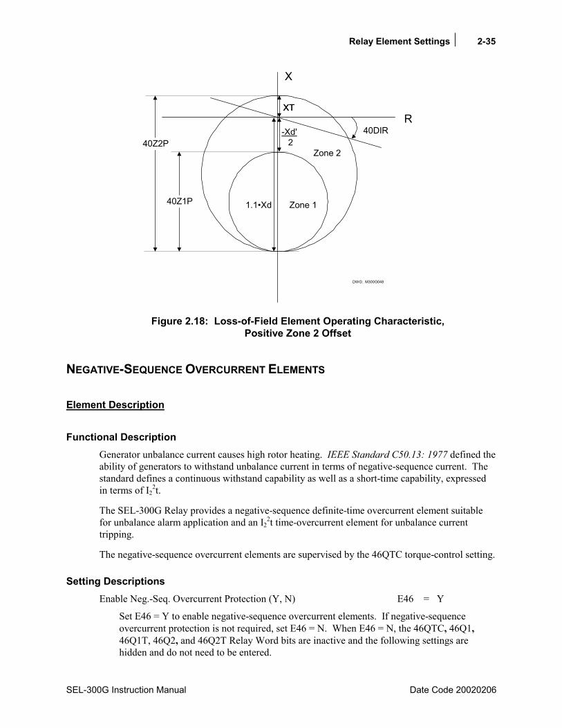
Relay Element Settings 2-35
SEL-300G Instruction Manual Date Code 20020206
X
DWG: M300G048
R-Xd' 2
40Z1P
40Z2P
XTXT
40DIR
Zone 1
Zone 2
1.1Xd
Figure 2.18: Loss-of-Field Element Operating Characteristic, Positive Zone 2 Offset
NEGATIVE-SEQUENCE OVERCURRENT ELEMENTS
Element Description
Functional Description Generator unbalance current causes high rotor heating. IEEE Standard C50.13: 1977 defined the ability of generators to withstand unbalance current in terms of negative-sequence current. The standard defines a continuous withstand capability as well as a short-time capability, expressed in terms of I2
2t.
The SEL-300G Relay provides a negative-sequence definite-time overcurrent element suitable for unbalance alarm application and an I2
2t time-overcurrent element for unbalance current tripping.
The negative-sequence overcurrent elements are supervised by the 46QTC torque-control setting.
Setting Descriptions Enable Neg.-Seq. Overcurrent Protection (Y, N) E46 = Y
Set E46 = Y to enable negative-sequence overcurrent elements. If negative-sequence overcurrent protection is not required, set E46 = N. When E46 = N, the 46QTC, 46Q1, 46Q1T, 46Q2, and 46Q2T Relay Word bits are inactive and the following settings are hidden and do not need to be entered.
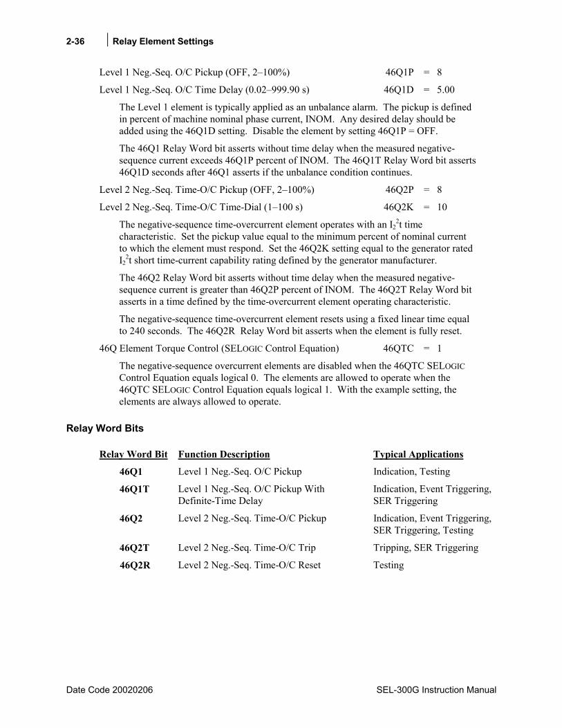
2-36 Relay Element Settings
Date Code 20020206 SEL-300G Instruction Manual
Level 1 Neg.-Seq. O/C Pickup (OFF, 2100%) 46Q1P = 8
Level 1 Neg.-Seq. O/C Time Delay (0.02999.90 s) 46Q1D = 5.00
The Level 1 element is typically applied as an unbalance alarm. The pickup is defined in percent of machine nominal phase current, INOM. Any desired delay should be added using the 46Q1D setting. Disable the element by setting 46Q1P = OFF.
The 46Q1 Relay Word bit asserts without time delay when the measured negative-sequence current exceeds 46Q1P percent of INOM. The 46Q1T Relay Word bit asserts 46Q1D seconds after 46Q1 asserts if the unbalance condition continues.
Level 2 Neg.-Seq. Time-O/C Pickup (OFF, 2100%) 46Q2P = 8
Level 2 Neg.-Seq. Time-O/C Time-Dial (1100 s) 46Q2K = 10
The negative-sequence time-overcurrent element operates with an I22t time
characteristic. Set the pickup value equal to the minimum percent of nominal current to which the element must respond. Set the 46Q2K setting equal to the generator rated I2
2t short time-current capability rating defined by the generator manufacturer.
The 46Q2 Relay Word bit asserts without time delay when the measured negative-sequence current is greater than 46Q2P percent of INOM. The 46Q2T Relay Word bit asserts in a time defined by the time-overcurrent element operating characteristic.
The negative-sequence time-overcurrent element resets using a fixed linear time equal to 240 seconds. The 46Q2R Relay Word bit asserts when the element is fully reset.
46Q Element Torque Control (SELOGIC Control Equation) 46QTC = 1
The negative-sequence overcurrent elements are disabled when the 46QTC SELOGIC Control Equation equals logical 0. The elements are allowed to operate when the 46QTC SELOGIC Control Equation equals logical 1. With the example setting, the elements are always allowed to operate.
Relay Word Bits
Relay Word Bit Function Description Typical Applications
46Q1 Level 1 Neg.-Seq. O/C Pickup Indication, Testing
46Q1T Level 1 Neg.-Seq. O/C Pickup With Definite-Time Delay
Indication, Event Triggering, SER Triggering
46Q2 Level 2 Neg.-Seq. Time-O/C Pickup Indication, Event Triggering, SER Triggering, Testing
46Q2T Level 2 Neg.-Seq. Time-O/C Trip Tripping, SER Triggering
46Q2R Level 2 Neg.-Seq. Time-O/C Reset Testing
Relay Element Settings 2-37
SEL-300G Instruction Manual Date Code 20020206
Setting Calculation
Information Needed
• Generator continuous current unbalance withstand capability, percent of rated current
• Generator negative-sequence current short-time withstand capability, seconds
Recommendations Set the 46Q1P equal to or just greater than the generator continuous unbalance current capability.
12%846Q1P =
Set the 46Q1D time delay greater than the maximum system phase-fault clearing time. This delay setting will prevent undesired unbalance current alarms for system faults that are cleared normally.
seconds 5.046Q1D =
Set the 46Q2P setting greater than the generator continuous unbalance current capability.
12%846Q2P =
Set the 46Q2K setting equal to the generator short-time negative-sequence current capability.
1046Q2K =
If there are operating conditions under which you wish to prevent negative-sequence overcurrent element operation, define those conditions in the 46QTC torque-control setting. Normally, the negative-sequence overcurrent elements should be enabled all the time.
146QTC =
Negative-Sequence Overcurrent Tripping Negative-sequence overcurrent tripping generally is applied to the generator main breaker only. This permits rapid resynchronization after the system unbalance condition is cleared. Refer to Section 4: SELOGIC® Control Equations for more detail and examples of tripping SELOGIC Control Equations.
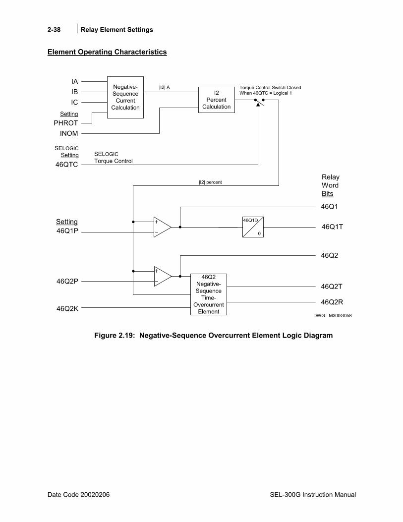
2-38 Relay Element Settings
Date Code 20020206 SEL-300G Instruction Manual
Element Operating Characteristics
46Q1D
0
DWG: M300G058
46Q1T46Q1P
46Q2Negative-Sequence
Time-Overcurrent
Element
Negative-Sequence
CurrentCalculation
46Q2K
46QTCSELOGICTorque Control
I2Percent
Calculation
IAIBIC
SettingPHROT
INOM
SELOGICSetting
46Q2
46Q1
46Q2T
46Q2R
Setting
46Q2P
|I2| percent
Torque Control Switch ClosedWhen 46QTC = Logical 1
|I2| A
RelayWordBits
Figure 2.19: Negative-Sequence Overcurrent Element Logic Diagram
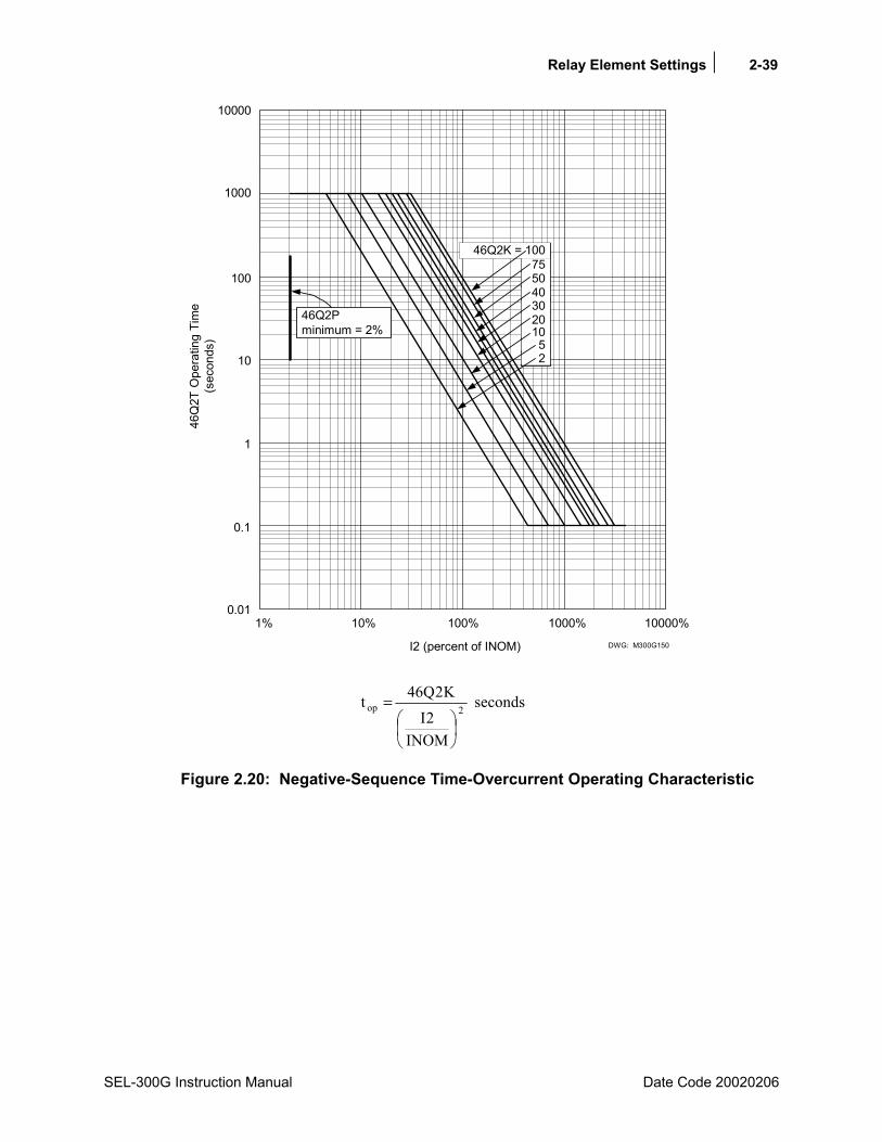
Relay Element Settings 2-39
SEL-300G Instruction Manual Date Code 20020206
1%0.01
0.1
1
10
100
10% 100% 1000% 10000%
I2 (percent of INOM)
1000
10000
46Q2K = 10075504030201052
46Q2Pminimum = 2%
46Q
2T O
pera
ting
Tim
e(s
econ
ds)
DWG: M300G150
2op
INOM2I
K2Q46t
= seconds
Figure 2.20: Negative-Sequence Time-Overcurrent Operating Characteristic

2-40 Relay Element Settings
Date Code 20020206 SEL-300G Instruction Manual
OVERCURRENT ELEMENTS
Element Description
Functional Description The SEL-300G Relay offers an assortment of nondedicated overcurrent elements for protection, indication, and control functions.
Overcurrent Protection, All Relay Models
All relay models provide the following overcurrent elements:
• Two levels of phase definite-time overcurrent, 50P1 and 50P2
• Two levels of neutral definite-time overcurrent, 50N1 and 50N2
• Two levels of residual ground definite-time overcurrent, 50G1 and 50G2
• One level of neutral inverse-time overcurrent, 51N
• One level of residual inverse-time overcurrent, 51G
Phase overcurrent elements operate using the maximum of the measured phase current magnitudes. The neutral overcurrent elements operate using the magnitude of the neutral current input. Residual ground overcurrent elements operate using the sum of the three-phase current inputs.
Where you use the relay to protect high-impedance grounded or resistance grounded generators, the neutral overcurrent elements provide stator ground fault detection for faults in the upper area of the winding when connected to a generator neutral current transformer, as shown in Section 5: Installation. The 50P, 50N, and 50G elements may be set sensitively and applied for inadvertent energization protection, as described in Section 4: SELOGIC® Control Equations.
Where you use the relay to protect solidly grounded generators, the phase, neutral, and residual overcurrent elements can all respond to stator ground faults in the mid- and upper-winding areas.
Overcurrent Protection, Relay Models With Differential Protection
Relay models with differential protection functions add the following overcurrent elements:
• Two levels of phase definite-time overcurrent, 50H1 and 50H2
• Two levels of negative-sequence definite-time overcurrent, 50Q1 and 50Q2
• Two levels of residual ground definite-time overcurrent, 50R1 and 50R2
The 50H1 phase overcurrent element operates using the maximum of the measured phase current inputs from the IA87, IB87, and IC87 phase current inputs. The 50Q1 and 50Q2 elements operate using the magnitude of the negative-sequence current, I2, calculated from the IA87, IB87, and IC87 phase current inputs. The 50R1 and 50R2 residual ground overcurrent elements operate using the magnitude of the sum of the IA87, IB87, and IC87 phase current inputs. In applications where the generator is connected directly to a bus, you can use the 50H and 50R

Relay Element Settings 2-41
SEL-300G Instruction Manual Date Code 20020206
elements to provide effective breaker failure protection, as described in Section 4: SELOGIC® Control Equations.
The 50H2 phase overcurrent element is three single-phase overcurrent elements with individual pickup settings per phase. When the I_87 inputs are applied with window CTs for self-balancing differential protection (see Figure 5.21), you can set the phase overcurrent element pickups differently. This may be necessary to accommodate different levels of winding current unbalance among the phases.
Setting Descriptions Enable O/C Protection (Y, N) E50 = Y
Set E50 = Y to enable the 50P1, 50P2, 50N1, 50N2, 50G1, and 50G2 definite-time overcurrent elements. If none of these overcurrent elements is required, set E50 = N. When E50 = N, the elements listed above are inactive and their pickup and time-delay settings are hidden and do not need to be entered.
Enable 87-Input O/C Protection (Y, N) E50_87 = Y
Note: This setting is not offered if the relay model is not equipped with current differential protection functions.
Set E50_87 = Y to enable the 50H1, 50H2, 50Q1, 50Q2, 50R1, and 50R2 definite-time overcurrent elements. If none of these overcurrent elements is required, set E50_87 = N. When E50_87 = N, the elements listed above are inactive and their pickup and time-delay settings are hidden and do not need to be entered.
Enable Time-O/C Elements (Y, N) E51 = Y
Set E51 = Y to enable the 51N and 51G inverse-time overcurrent elements. If none of these overcurrent elements is required, set E51 = N. When E51 = N, the elements listed above are inactive and their settings are hidden and do not need to be entered. Voltage-controlled and voltage-restrained time-overcurrent elements are enabled separately.
Note: All setting ranges shown below are for 5 A relay models. Relays equipped for use with 1 A current transformers provide overcurrent element setting ranges of 0.05 to 20 A secondary.
Definite-Time Overcurrent Settings Level 1 Phase O/C Pickup (OFF, 0.25100.00 A) 50P1P = 8.00
Level 1 Phase O/C Time Delay (0.00400.00 s) 50P1D = 30.00
Level 2 Phase O/C Pickup (OFF, 0.25100.00 A) 50P2P = 8.00
Level 2 Phase O/C Time Delay (0.00400.00 s) 50P2D = 30.00
Level 1 Neutral Ground O/C Pickup (OFF, 0.25100.00 A) 50N1P = 2.50
Level 1 Neutral Ground O/C Time Delay (0.00400.00 s) 50N1D = 0.10
Level 2 Neutral Ground O/C Pickup (OFF, 0.25100.00 A) 50N2P = 8.00
Level 2 Neutral Ground O/C Time Delay (0.00400.00 s) 50N2D = 30.00
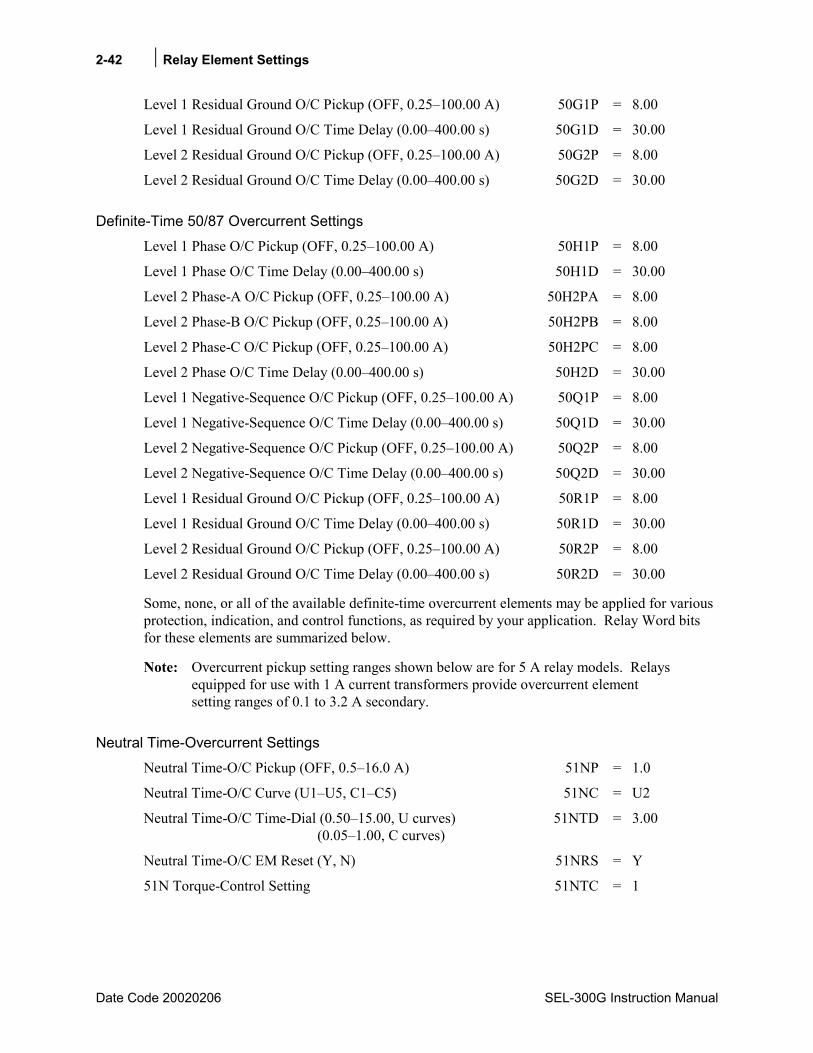
2-42 Relay Element Settings
Date Code 20020206 SEL-300G Instruction Manual
Level 1 Residual Ground O/C Pickup (OFF, 0.25100.00 A) 50G1P = 8.00
Level 1 Residual Ground O/C Time Delay (0.00400.00 s) 50G1D = 30.00
Level 2 Residual Ground O/C Pickup (OFF, 0.25100.00 A) 50G2P = 8.00
Level 2 Residual Ground O/C Time Delay (0.00400.00 s) 50G2D = 30.00
Definite-Time 50/87 Overcurrent Settings Level 1 Phase O/C Pickup (OFF, 0.25100.00 A) 50H1P = 8.00
Level 1 Phase O/C Time Delay (0.00400.00 s) 50H1D = 30.00
Level 2 Phase-A O/C Pickup (OFF, 0.25100.00 A) 50H2PA = 8.00
Level 2 Phase-B O/C Pickup (OFF, 0.25100.00 A) 50H2PB = 8.00
Level 2 Phase-C O/C Pickup (OFF, 0.25100.00 A) 50H2PC = 8.00
Level 2 Phase O/C Time Delay (0.00400.00 s) 50H2D = 30.00
Level 1 Negative-Sequence O/C Pickup (OFF, 0.25100.00 A) 50Q1P = 8.00
Level 1 Negative-Sequence O/C Time Delay (0.00400.00 s) 50Q1D = 30.00
Level 2 Negative-Sequence O/C Pickup (OFF, 0.25100.00 A) 50Q2P = 8.00
Level 2 Negative-Sequence O/C Time Delay (0.00400.00 s) 50Q2D = 30.00
Level 1 Residual Ground O/C Pickup (OFF, 0.25100.00 A) 50R1P = 8.00
Level 1 Residual Ground O/C Time Delay (0.00400.00 s) 50R1D = 30.00
Level 2 Residual Ground O/C Pickup (OFF, 0.25100.00 A) 50R2P = 8.00
Level 2 Residual Ground O/C Time Delay (0.00400.00 s) 50R2D = 30.00
Some, none, or all of the available definite-time overcurrent elements may be applied for various protection, indication, and control functions, as required by your application. Relay Word bits for these elements are summarized below.
Note: Overcurrent pickup setting ranges shown below are for 5 A relay models. Relays equipped for use with 1 A current transformers provide overcurrent element setting ranges of 0.1 to 3.2 A secondary.
Neutral Time-Overcurrent Settings Neutral Time-O/C Pickup (OFF, 0.516.0 A) 51NP = 1.0
Neutral Time-O/C Curve (U1U5, C1C5) 51NC = U2
Neutral Time-O/C Time-Dial (0.5015.00, U curves) 51NTD = 3.00 (0.051.00, C curves)
Neutral Time-O/C EM Reset (Y, N) 51NRS = Y
51N Torque-Control Setting 51NTC = 1
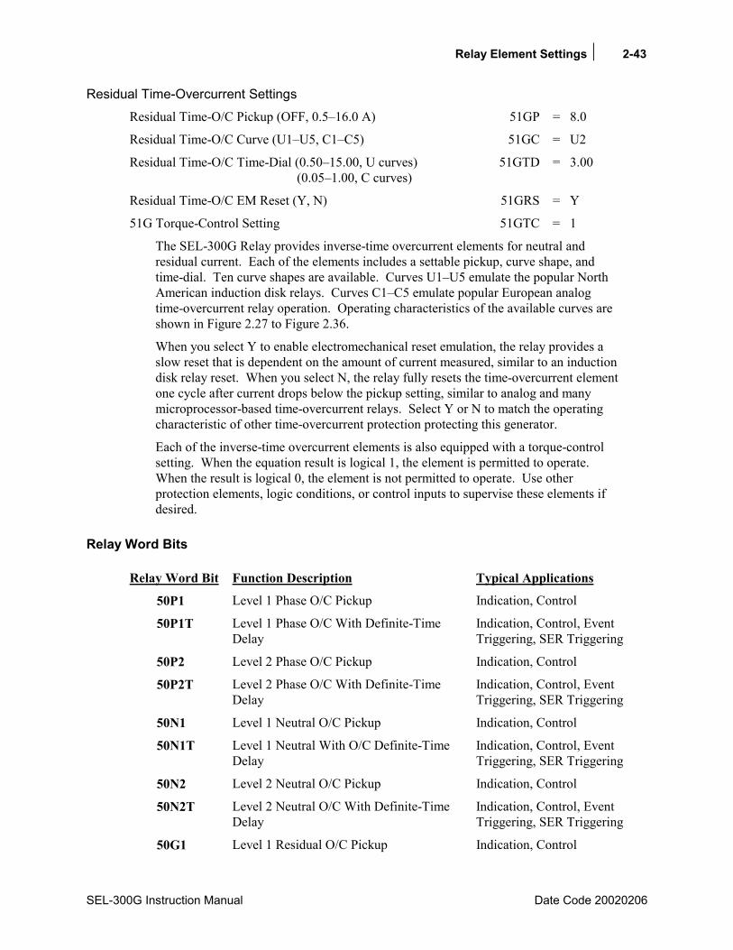
Relay Element Settings 2-43
SEL-300G Instruction Manual Date Code 20020206
Residual Time-Overcurrent Settings Residual Time-O/C Pickup (OFF, 0.516.0 A) 51GP = 8.0
Residual Time-O/C Curve (U1U5, C1C5) 51GC = U2
Residual Time-O/C Time-Dial (0.5015.00, U curves) 51GTD = 3.00 (0.051.00, C curves)
Residual Time-O/C EM Reset (Y, N) 51GRS = Y
51G Torque-Control Setting 51GTC = 1
The SEL-300G Relay provides inverse-time overcurrent elements for neutral and residual current. Each of the elements includes a settable pickup, curve shape, and time-dial. Ten curve shapes are available. Curves U1U5 emulate the popular North American induction disk relays. Curves C1C5 emulate popular European analog time-overcurrent relay operation. Operating characteristics of the available curves are shown in Figure 2.27 to Figure 2.36.
When you select Y to enable electromechanical reset emulation, the relay provides a slow reset that is dependent on the amount of current measured, similar to an induction disk relay reset. When you select N, the relay fully resets the time-overcurrent element one cycle after current drops below the pickup setting, similar to analog and many microprocessor-based time-overcurrent relays. Select Y or N to match the operating characteristic of other time-overcurrent protection protecting this generator.
Each of the inverse-time overcurrent elements is also equipped with a torque-control setting. When the equation result is logical 1, the element is permitted to operate. When the result is logical 0, the element is not permitted to operate. Use other protection elements, logic conditions, or control inputs to supervise these elements if desired.
Relay Word Bits
Relay Word Bit Function Description Typical Applications
50P1 Level 1 Phase O/C Pickup Indication, Control
50P1T Level 1 Phase O/C With Definite-Time Delay
Indication, Control, Event Triggering, SER Triggering
50P2 Level 2 Phase O/C Pickup Indication, Control
50P2T Level 2 Phase O/C With Definite-Time Delay
Indication, Control, Event Triggering, SER Triggering
50N1 Level 1 Neutral O/C Pickup Indication, Control
50N1T Level 1 Neutral With O/C Definite-Time Delay
Indication, Control, Event Triggering, SER Triggering
50N2 Level 2 Neutral O/C Pickup Indication, Control
50N2T Level 2 Neutral O/C With Definite-Time Delay
Indication, Control, Event Triggering, SER Triggering
50G1 Level 1 Residual O/C Pickup Indication, Control
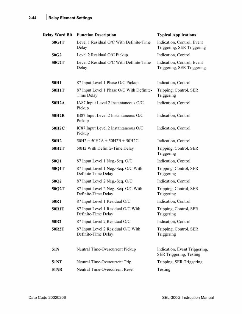
2-44 Relay Element Settings
Date Code 20020206 SEL-300G Instruction Manual
Relay Word Bit Function Description Typical Applications
50G1T Level 1 Residual O/C With Definite-Time Delay
Indication, Control, Event Triggering, SER Triggering
50G2 Level 2 Residual O/C Pickup Indication, Control
50G2T Level 2 Residual O/C With Definite-Time Delay
Indication, Control, Event Triggering, SER Triggering
50H1 87 Input Level 1 Phase O/C Pickup Indication, Control
50H1T 87 Input Level 1 Phase O/C With Definite-Time Delay
Tripping, Control, SER Triggering
50H2A IA87 Input Level 2 Instantaneous O/C Pickup
Indication, Control
50H2B IB87 Input Level 2 Instantaneous O/C Pickup
Indication, Control
50H2C IC87 Input Level 2 Instantaneous O/C Pickup
Indication, Control
50H2 50H2 = 50H2A + 50H2B + 50H2C Indication, Control
50H2T 50H2 With Definite-Time Delay Tripping, Control, SER Triggering
50Q1 87 Input Level 1 Neg.-Seq. O/C Indication, Control
50Q1T 87 Input Level 1 Neg.-Seq. O/C With Definite-Time Delay
Tripping, Control, SER Triggering
50Q2 87 Input Level 2 Neg.-Seq. O/C Indication, Control
50Q2T 87 Input Level 2 Neg.-Seq. O/C With Definite-Time Delay
Tripping, Control, SER Triggering
50R1 87 Input Level 1 Residual O/C Indication, Control
50R1T 87 Input Level 1 Residual O/C With Definite-Time Delay
Tripping, Control, SER Triggering
50R2 87 Input Level 2 Residual O/C Indication, Control
50R2T 87 Input Level 2 Residual O/C With Definite-Time Delay
Tripping, Control, SER Triggering
51N Neutral Time-Overcurrent Pickup Indication, Event Triggering, SER Triggering, Testing
51NT Neutral Time-Overcurrent Trip Tripping, SER Triggering
51NR Neutral Time-Overcurrent Reset Testing
Relay Element Settings 2-45
SEL-300G Instruction Manual Date Code 20020206
Relay Word Bit Function Description Typical Applications
51G Residual Time-Overcurrent Pickup Indication, Event Triggering, SER Triggering, Testing
51GT Residual Time-Overcurrent trip Tripping, SER Triggering
51GR Residual Time-Overcurrent reset Testing
Neutral Overcurrent Setting Calculation
Information Needed
• Generator terminal ground fault current, In, A primary
• Generator grounding transformer ratio to 1 (in high-impedance grounded protection applications)
• Neutral CT transformer ratio to 1
Recommendations In all applications where a neutral current transformer is connected between the generator neutral point and ground or in the secondary of the generator grounding transformer, you can apply the neutral overcurrent elements 51N and 50N1 for stator ground fault detection.
Warning: Generator neutral overcurrent protection cannot detect stator winding faults at or near the generator neutral point, nor is it effective while the generator grounding circuit is opened. In resistance and high-impedance grounded generator applications, use this relays 100% stator ground protection to ensure that all stator winding faults are detected.
Set the 51NP equal to or just greater than the element minimum pickup setting.
Α 0.551NP =
An inverse curve shape (U2) and time-dial of 3.0 provide 6.5 second tripping for 1.0 A secondary faults.
3.051NTDU251NC
=
=
Electromechanical reset emulation is not necessary and this element may be in service continuously so the torque-control setting is logical 1.
151NTCN51RS
=
=

2-46 Relay Element Settings
Date Code 20020206 SEL-300G Instruction Manual
You can determine the lower boundary of stator winding coverage provided by this element using the equation:
( ) %100
CTRNNIn
51NP2%x
=
Where In = generator ground fault current, A primary N = grounding transformer voltage ratio to 1,
(use 1 in solidly grounded or resistance grounded applications) CTRN = neutral current transformer ratio to 1
Ground faults occurring above the winding point calculated above are detected and a trip generated by the 51N time-overcurrent element in under 6.5 seconds, using the settings above.
The 50N1P element can provide a definite-time delayed trip for ground faults occurring higher in the stator winding, between the generator and the step-up transformer, or within the step-up transformer delta windings. A 50N1P setting of four to five times the 51NP setting will reduce the 50N1P element sensitivity to system ground faults, while still providing detection of ground faults high in the stator winding.
timeclearingfault ground systemon depending second, 0.5 to1.1050N1D51NP times5 to450N1P
=
=
Set the 50N1D delay time greater than the maximum clearing time for system ground faults that can be detected by the 50N1P element.
Neutral Overcurrent Tripping Because the neutral overcurrent elements detect generator faults of a serious nature, tripping generally is applied to the generator main breaker, the field breaker, and the prime mover. Refer to Section 4: SELOGIC® Control Equations for more detail and examples of tripping SELOGIC Control Equations.
Other Overcurrent Elements Enable and apply those phase, neutral, and residual overcurrent elements that are required for your specific control scheme. Pickup settings and time delays are governed by the requirements of the application. Set the pickup of unused elements to OFF.
Element Operating Characteristics
Pickup and Reset Time Curves Figure 2.21 and Figure 2.22 show pickup and reset time curves applicable to all instantaneous overcurrent elements in the SEL-300G Relay. These times do not include output contact operating time and are accurate for determining element operation time for use in internal SELOGIC Control Equations. Output contact pickup/dropout time is less than 5 ms.
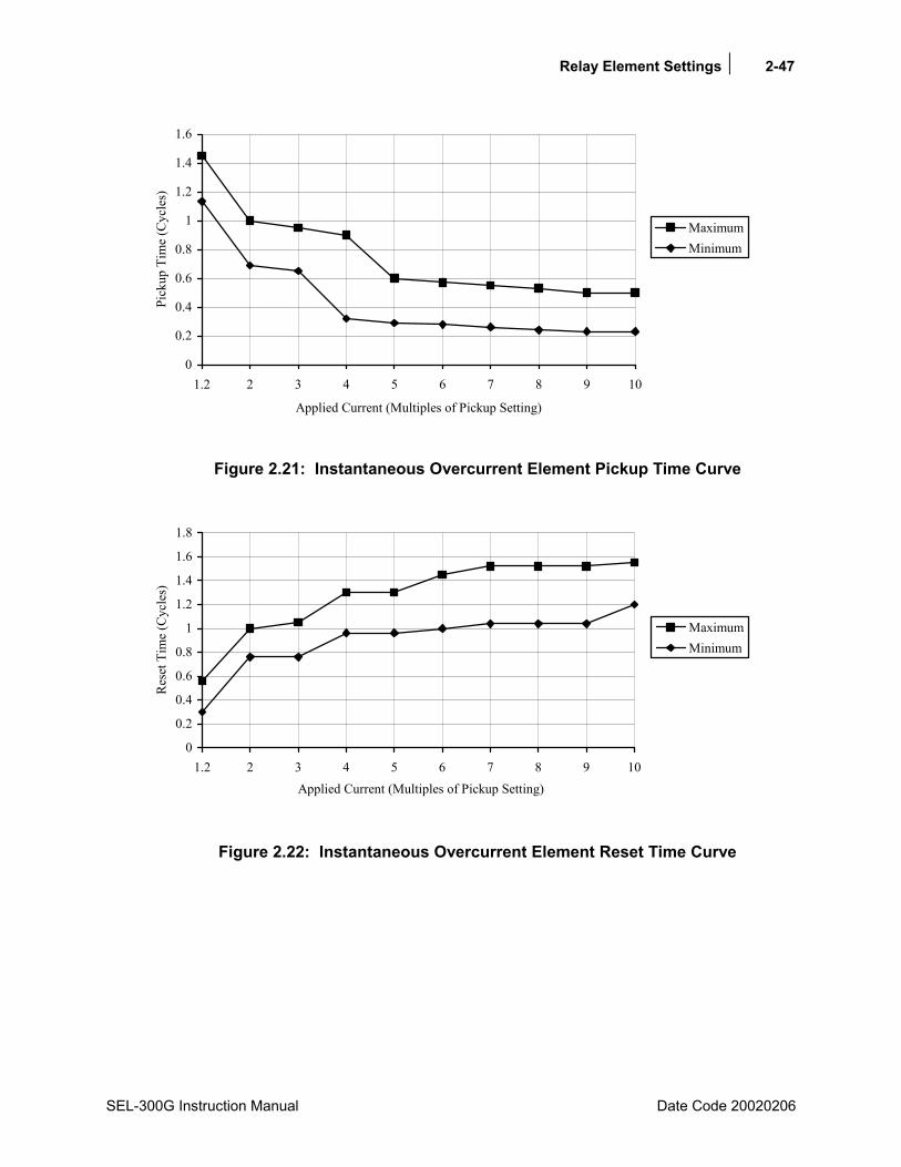
Relay Element Settings 2-47
SEL-300G Instruction Manual Date Code 20020206
0
0.2
0.4
0.6
0.8
1
1.2
1.4
1.6
1.2 2 3 4 5 6 7 8 9 10
Applied Current (Multiples of Pickup Setting)
Pick
up T
ime
(Cyc
les)
MaximumMinimum
Figure 2.21: Instantaneous Overcurrent Element Pickup Time Curve
0
0.2
0.4
0.6
0.8
1
1.2
1.4
1.6
1.8
1.2 2 3 4 5 6 7 8 9 10Applied Current (Multiples of Pickup Setting)
Res
et T
ime
(Cyc
les)
MaximumMinimum
Figure 2.22: Instantaneous Overcurrent Element Reset Time Curve
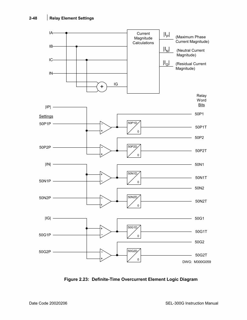
2-48 Relay Element Settings
Date Code 20020206 SEL-300G Instruction Manual
CurrentMagnitude
Calculations(Maximum PhaseCurrent Magnitude)
50P1D
050P1T
50P1P
50P1
50P2D
050P2T
50P2P
50P2
|IP|
+ IG
(Neutral CurrentMagnitude)
(Residual CurrentMagnitude)
50N1D
050N1T
50N1P
50N1
50N2D
050N2T
50N2P
50N2
|IN|
50G1D
050G1T
50G1P
50G1
50G2D
050G2T
50G2
|IG|
IN
IC
IB
IA
DWG: M300G059
Settings
RelayWordBits
|IP|
|IN|
|IG|
50G2P
Figure 2.23: Definite-Time Overcurrent Element Logic Diagram
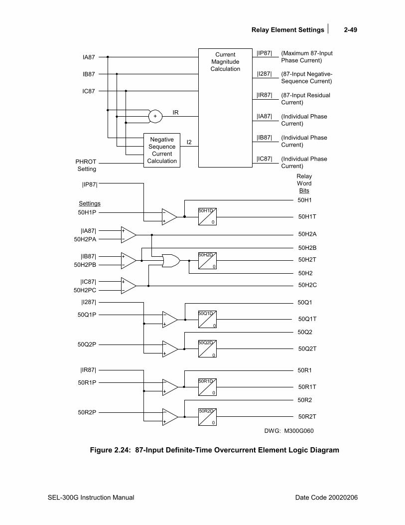
Relay Element Settings 2-49
SEL-300G Instruction Manual Date Code 20020206
50H1T50H1P
50H1
|IP87|
50Q1D
050Q1T
50Q1P
50Q1
50Q2D
050Q2T
50Q2P
50Q2
|I287|
50R1D
050R1T
50R1P
50R1
50R2D
050R2T
50R2P
50R2
|IR87|
DWG: M300G060
CurrentMagnitudeCalculation
NegativeSequence
CurrentCalculation
+
PHROTSetting
IA87
IB87
IC87
IR
I2
|IP87|
|I287|
|IA87|
(Maximum 87-InputPhase Current)
(87-Input Negative-Sequence Current)
(Individual PhaseCurrent)
Settings
RelayWordBits
|IB87| (Individual PhaseCurrent)
|IC87| (Individual PhaseCurrent)
|IR87| (87-Input ResidualCurrent)
50H1D
0
50H2D
0
|IA87|50H2PA
|IB87|50H2PB
|IC87|50H2PC
50H2A
50H2B
50H2T
50H2
50H2C
Figure 2.24: 87-Input Definite-Time Overcurrent Element Logic Diagram
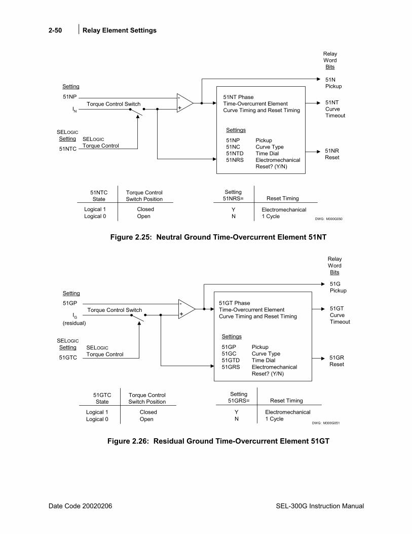
2-50 Relay Element Settings
Date Code 20020206 SEL-300G Instruction Manual
SELOGICTorque Control51NTC 51NR
Reset
51NTCurveTimeout
1 Cycle
Reset Timing
Electromechanical
Setting51NRS=
NY
Torque ControlSwitch Position
51NTCState
OpenClosed
Logical 0Logical 1
51NPickup
51NP Pickup51NC Curve Type51NTD Time Dial51NRS Electromechanical
Reset? (Y/N)
Settings
51NT PhaseTime-Overcurrent ElementCurve Timing and Reset Timing
51NPTorque Control Switch
RelayWordBits
Setting
+-
IN
SELOGICSetting
DWG: M300G050
Figure 2.25: Neutral Ground Time-Overcurrent Element 51NT
SELOGICTorque Control51GTC 51GR
Reset
51GTCurveTimeout
1 Cycle
Reset Timing
Electromechanical
Setting51GRS=
NY
Torque ControlSwitch Position
51GTCState
OpenClosed
Logical 0Logical 1
51GPickup
51GP Pickup51GC Curve Type51GTD Time Dial51GRS Electromechanical
Reset? (Y/N)
Settings
51GT PhaseTime-Overcurrent ElementCurve Timing and Reset Timing
51GPTorque Control Switch
RelayWordBits
Setting
+-
IG
SELOGICSetting
DWG: M300G051
(residual)
Figure 2.26: Residual Ground Time-Overcurrent Element 51GT

Relay Element Settings 2-51
SEL-300G Instruction Manual Date Code 20020206
TIME-OVERCURRENT CURVES The following information describes the curve timing for the curve and time-dial settings made for the time-overcurrent elements. The time-overcurrent relay curves in Figure 2.27 through Figure 2.31 conform to IEEE C37.112: 1996 IEEE Standard Inverse-Time Characteristic Equations for Overcurrent Relays.
tp = operating time in seconds tr = electromechanical induction-disk emulation reset time in seconds
(if electromechanical reset setting is made) TD = time-dial setting M = applied multiples of pickup current [for operating time (tp), M>1; for reset time (tr),
M≤1]. U.S. Moderately Inverse Curve: U1
( )
( )
−=
−+=
2
02.0
M108.1TDtr
1M0104.00226.0TDtp
U.S. Inverse Curve: U2
( )
( )
−•=
−+•=
2
2
M195.5TDtr
1M95.5180.0TDtp
U.S. Very Inverse Curve: U3
( )
( )
−=
−+=
2
2
M188.3TDtr
1M88.30963.0TDtp
U.S. Extremely Inverse Curve: U4
( )
( )
−=
−+=
2
2
M167.5TDtr
1M67.50352.0TDtp
U.S. Short-Time Inverse Curve: U5
( )
( )
−=
−+=
2
02.0
M1323.0TDtr
1M00342.000262.0TDtp
I.E.C. Class A Curve (Standard Inverse): C1
( )
( )
−=
−=
2
02.0
M15.13TDtr
1M14.0TDtp
I.E.C. Class B Curve (Very Inverse): C2
( )
( )
−=
−=
2M13.47TDtr
1M5.13TDtp
I.E.C. Class C Curve (Extremely Inverse): C3
( )
( )
−=
−=
2
2
M10.80TDtr
1M0.80TDtp
I.E.C. Long-Time Inverse Curve: C4
( )
( )
−=
−=
M10.120TDtr
1M0.120TDtp
I.E.C. Short-Time Inverse Curve: C5
( )
( )
−=
−=
2
04.0
M185.4TDtr
1M05.0TDtp
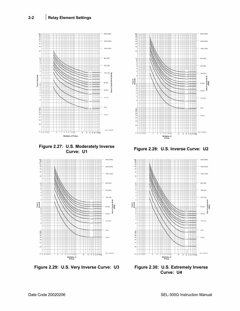
2-2 Relay Element Settings
Date Code 20020206 SEL-300G Instruction Manual
0.50
1.00
2.00
3.00
4.00
5.006.00
8.00
10.00
12.00
15.00
10
20
30
40
5060708090
100
1
2
3
4
5
6789
.1
.2
.3
.4
.5
.6
.7
.8
.9
.01
.02
.03
.04
.05
.06
.07
.08
.09
1001 2 3 4 5 6 7 8 9.5 .6 .7 .8 .9 908070605040302010
Tim
e in
Sec
onds
Tim
e in
Cyc
les
60 H
z (5
0 H
z)
6000 (5000)
3000 (2500)
1500 (1250)
600 (500)
300 (250)
150 (125)
60 (50)
30 (25)
15 (12.5)
6 (5)
3 (2.5)
DWG: M300G097
Multiples of Pickup
Figure 2.27: U.S. Moderately Inverse Curve: U1
0.50
1.00
2.00
3.00
4.00
5.006.00
8.00
10.0012.00
15.00
10
20
30
40
5060708090
100
1
2
3
4
56789
.1
.2
.3
.4
.5
.6
.7
.8
.9
.01
.02
.03
.04
.05
.06
.07
.08
.09
1 2 3 4 5 6 7 8 9.5 .6 .7 .8 .9Ti
me
inSe
cond
s
Tim
e in
Cyc
les
60 H
z(5
0Hz)
6000 (5000)
3000 (2500)
1500 (1250)
600 (500)
300 (250)
150 (125)
60 (50)
30 (25)
15 (12.5)
6 (5)
3 (2.5)
DWG: M300G098
Multiples ofPickup
100908070605040302010
Figure 2.28: U.S. Inverse Curve: U2
0.50
1.00
2.00
3.00
4.00
5.006.00
8.00
10.0012.00
15.00
10
20
30
40
5060
708090
100
1
2
3
4
56789
.1
.2
.3
.4
.5
.6
.7
.8
.9
.01
.02
.03
.04
.05
.06
.07
.08
.09
1001 2 3 4 5 6 7 8 9.5 .6 .7 .8 .9 908070605040302010
Tim
e in
Seco
nds
Tim
e in
Cyc
les
60 H
z(5
0Hz)
6000 (5000)
3000 (2500)
1500 (1250)
600 (500)
300 (250)
150 (125)
60 (50)
30 (25)
15 (12.5)
6 (5)
3 (2.5)
DWG: M300G100
Multiples ofPickup
Figure 2.29: U.S. Very Inverse Curve: U3
0.50
1.00
2.00
3.00
4.00
5.006.00
8.00
10.0012.00
15.00
10
20
30
40
5060708090
100
1
2
3
4
56789
.1
.2
.3
.4
.5
.6
.7
.8
.9
.01
.02
.03
.04
.05
.06
.07
.08
.09
1001 2 3 4 5 6 7 8 9.5 .6 .7 .8 .9 908070605040302010
Tim
e in
Seco
nds
Tim
e in
Cyc
les
60 H
z(5
0Hz)
6000 (5000)
3000 (2500)
1500 (1250)
600 (500)
300 (250)
150 (125)
60 (50)
30 (25)
15 (12.5)
6 (5)
3 (2.5)
DWG: M300G101
Multiples ofPickup
Figure 2.30: U.S. Extremely Inverse Curve: U4
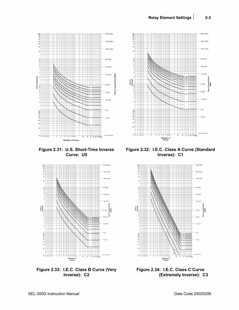
Relay Element Settings 2-3
SEL-300G Instruction Manual Date Code 20020206
10
20
30
40
5060708090
100
1
2
3
4
56789
.1
.2
.3
.4
.5
.6
.7
.8
.9
.01
.02
.03
.04
.05
.06
.07
.08
.09
1001 2 3 4 5 6 7 8 9.5 .6 .7 .8.9 908070605040302010
Tim
e in
Sec
onds
Tim
e in
Cyc
les
60 H
z (5
0Hz)
6000 (5000)
3000 (2500)
1500 (1250)
600 (500)
300 (250)
150 (125)
60 (50)
30 (25)
15 (12.5)
6 (5)
3 (2.5)
DWG: M300G197
Multiples of Pickup
0.50
1.00
2.00
3.00
4.00
5.006.00
8.00
10.0012.00
15.00
Figure 2.31: U.S. Short-Time Inverse Curve: U5
0.05
0.10
0.20
0.30
0.40
0.500.600.700.800.901.00
10
20
30
40
5060708090
100
1
2
3
4
56789
.1
.2
.3
.4
.5
.6
.7
.8
.9
.01
.02
.03
.04
.05
.06
.07
.08
.09
1001 2 3 4 5 6 7 8 9.5 .6 .7 .8 .9 908070605040302010
Tim
e in
Seco
nds
Tim
e in
Cyc
les
60 H
z(5
0Hz)
6000 (5000)
3000 (2500)
1500 (1250)
600 (500)
300 (250)
150 (125)
60 (50)
30 (25)
15 (12.5)
6 (5)
3 (2.5)
DWG: M300G115
Multiples ofPickup
Figure 2.32: I.E.C. Class A Curve (Standard Inverse): C1
0.05
0.10
0.20
0.30
0.40
0.500.600.700.800.901.00
10
20
30
40
5060708090
100
1
2
3
4
56789
.1
.2
.3
.4
.5
.6
.7
.8
.9
.01
.02
.03
.04
.05
.06
.07
.08
.09
1001 2 3 4 5 6 7 8 9.5 .6 .7 .8 .9 908070605040302010
Tim
e in
Seco
nds
Tim
e in
Cyc
les
60 H
z(5
0Hz)
6000 (5000)
3000 (2500)
1500 (1250)
600 (500)
300 (250)
150 (125)
60 (50)
30 (25)
15 (12.5)
6 (5)
3 (2.5)
DWG: M300G117
Multiples ofPickup
Figure 2.33: I.E.C. Class B Curve (Very Inverse): C2
0.05
0.10 0.20
0.30
0.40
0.500.600.700.800.901.00
10
20
30
40
5060708090
100
1
2
3
4
56789
.1
.2
.3
.4
.5
.6
.7
.8
.9
.01
.02
.03
.04
.05
.06
.07
.08
.09
1001 2 3 4 5 6 7 8 9.5 .6 .7 .8 .9 908070605040302010
Tim
e in
Seco
nds
Tim
e in
Cyc
les
60 H
z(5
0Hz)
6000 (5000)
3000 (2500)
1500 (1250)
600 (500)
300 (250)
150 (125)
60 (50)
30 (25)
15 (12.5)
6 (5)
3 (2.5)
DWG: M300G118
Multiples ofPickup
Figure 2.34: I.E.C. Class C Curve (Extremely Inverse): C3

2-4 Relay Element Settings
Date Code 20020206 SEL-300G Instruction Manual
100
200
300
400
500600700800900
1000
10
20
30
40
5060708090
1
2
3
4
56789
.1
.2
.3
.4
.5
.6
.7
.8
.9
0.05
0.10
0.20
0.30
0.40
0.500.600.700.800.901.00
1001 2 3 4 5 6 7 8 9.5 .6 .7 .8 .9 908070605040302010
Tim
e in
Seco
nds
Tim
e in
Cyc
les
60 H
z(5
0Hz)
60000 (50000)
30000 (25000)
15000 (12500)
6000 (5000)
3000 (2500)
1500 (1250)
600 (500)
300 (250)
150 (125)
60 (50)
30 (25)
DWG: M300G123
Multiples ofPickup
Figure 2.35: I.E.C. Long-Time Inverse Curve: C4
10
20
30
40
5060708090
100
1
2
3
4
56789
.1
.2
.3
.4
.5
.6
.7
.8
.9
.01
.02
.03
.04
.05
.06
.07
.08
.09
1001 2 3 4 5 6 7 8 9.5 .6 .7 .8.9 908070605040302010
Tim
e in
Sec
onds
Tim
e in
Cyc
les
60 H
z (5
0Hz)
6000 (5000)
3000 (2500)
1500 (1250)
600 (500)
300 (250)
150 (125)
60 (50)
30 (25)
15 (12.5)
6 (5)
3 (2.5)
DWG. M300G153
Multiples of Pickup
0.05
0.10
0.20
0.30
0.40
0.500.600.700.800.901.00
Figure 2.36: I.E.C. Short-Time Inverse Curve: C5
VOLTAGE-CONTROLLED/RESTRAINED TIME-OVERCURRENT ELEMENTS
Element Description
Functional Description The SEL-300G Relay provides a voltage-restrained phase time-overcurrent element and a voltage-controlled phase time-overcurrent element. One of these elements typically is used for system phase fault backup protection to trip the generator in the event of an uncleared phase fault on the system side of the step-up transformer.
The voltage-controlled phase time-overcurrent element, 51C, operates when its torque-control setting, 51CTC, is equal to logical 1. Typically, the torque-control setting should include the Relay Word bit for an undervoltage element, such as 27PP. This way, the 51C element operates only when a phase-to-phase voltage is less than the 27PP setting.
The voltage-restrained phase time-overcurrent element, 51V, also includes a torque-control setting, 51VTC. However, the 51V element operation is fundamentally different in that the element pickup setting automatically is reduced as the generator phase voltage decreases during a fault. When the generator voltage is 100% of the VNOM setting, the 51V element operates based on 100% of its pickup setting, 51VP. As the generator voltage drops, the relay decreases the element pickup by a like amount, down to 25% of nominal phase voltage. For voltages below 25%, the relay uses a pickup 25% of the 51VP setting.
Relay Element Settings 2-5
SEL-300G Instruction Manual Date Code 20020206
Setting Descriptions Enable System Backup Protection (N, D, V, C) EBUP = C
Set EBUP = C to enable the 51C voltage-controlled phase inverse-time overcurrent element. Set EBUP = V to enable the 51V voltage-restrained inverse-time overcurrent element. When EBUP = D or N, the elements listed above are disabled and the following settings do not need to be entered. (See Phase Mho Distance Element for the EBUP = D setting description.)
When EBUP = C:
Voltage-Controlled Time-O/C Pickup (OFF, 0.516.0 A 5 A Model; OFF, 0.13.2 A 1 A Model) 51CP = 3.0
Voltage-Controlled Time-O/C Curve (U1U5, C1C5) 51CC = U2
Voltage-Controlled Time-O/C Time-Dial (0.5015.00, U curves) 51CTD = 3.20 (0.051.00, C curves)
Voltage-Controlled Time-O/C EM Reset (Y, N) 51CRS = Y
51C Torque-Control Setting (SELOGIC Control Equation) 51CTC = 27PP*!60LOP
When EBUP = V:
Voltage-Restrained Time-O/C Pickup (OFF, 2.016.0 A 5 A Model; OFF, 0.43.2 A 1 A Model) 51VP = 8.0
Voltage-Restrained Time-O/C Curve (U1U5, C1C5) 51VC = U2
Voltage-Restrained Time-O/C Time-Dial (0.5015.00, U curves) 51VTD = 3.00 (0.051.00, C curves)
Voltage-Restrained Time-O/C EM Reset (Y, N) 51VRS = Y
51V Torque-Control Setting (SELOGIC Control Equation) 51VTC = !60LOP
For system backup protection, the SEL-300G Relay provides a choice of voltage-controlled or voltage-restrained phase inverse-time overcurrent elements or phase distance elements (discussed earlier in this section). The overcurrent elements include a settable pickup, curve shape, and time-dial. Ten curve shapes are available. Curves U1U5 emulate the popular North American induction disk relays. Curves C1C5 emulate popular European analog time-overcurrent relays. Operating characteristics of the available curves are shown in Figure 2.27 to Figure 2.36.
When you set 51nRS = Y to enable electromechanical reset emulation, the relay provides a slow reset that is dependent on the amount of current measured, similar to an induction disk relay reset. When you select N, the relay fully resets the time-overcurrent element one cycle after current drops below the pickup setting, similar to analog and many microprocessor-based time-overcurrent relays. Select Y or N to match the operating characteristic of other time-overcurrent protection protecting the system near this generator.
Each of the elements is also equipped with a torque-control setting. When the equation result is logical 1, the element is permitted to operate. When the result is logical 0, the element is not permitted to operate. Use other protection elements, logic conditions, or control inputs to supervise these elements if desired.
2-6 Relay Element Settings
Date Code 20020206 SEL-300G Instruction Manual
Relay Word Bits
Relay Word Bit Function Description Typical Applications
51C Voltage-Controlled Time-O/C Pickup Indication, Event Triggering, SER Triggering, Testing
51CT Voltage-Controlled Time-O/C Trip Tripping, SER Triggering
51CR Voltage-Controlled Time-O/C Reset Testing
51V Voltage-Restrained Time-O/C Pickup Indication, Event Triggering, SER Triggering, Testing
51VT Voltage-Restrained Time-O/C Trip Tripping, SER Triggering
51VR Voltage-Restrained Time-O/C Reset Testing
Voltage-Controlled and Voltage-Restrained Time-Overcurrent Setting Calculation
Information Needed • Generator nominal voltage, VNOM
• Generator current for long duration system phase fault, If, A primary
• Generator voltage for system phase fault, Vf, V primary
• Generator voltage and current transformer ratios to 1, PTR and CTR
Recommendations Choose either the voltage-controlled or voltage-restrained time-overcurrent element for system phase fault backup protection when overcurrent relays are used for primary system protection. Generally, the voltage-controlled element provides adequate backup protection and consistent performance. Use the voltage-restrained element if your protection standards or preferences require it.
Voltage-Controlled Time-Overcurrent Settings
Set the 51CP pickup setting less than the generator fault duty, calculated using the generator steady-state reactance, Xd (transient reactant Xd' may be used if the generator excitation system is able to support higher fault voltage and current). This value may safely be below maximum load, as the element is only enabled during low-voltage fault conditions. Divide the generator fault duty by the phase current transformer ratio, CTR, to find the element pickup current in secondary amps.
CTRIPCP51 ≤

Relay Element Settings 2-7
SEL-300G Instruction Manual Date Code 20020206
Select a curve shape and time-dial that allow this element to coordinate with the system primary protection.
3.0051CTDU251CC
=
=
Electromechanical reset emulation should be applied if the system phase overcurrent relays are induction disk relays; otherwise, electromechanical reset emulation is not necessary.
N51CRS =
By definition, this element should be torque controlled by an undervoltage element. To prevent misoperation if a potential transformer fuse blows, the element is also torque controlled by the !60LOP Relay Word bit.
!60LOP27PP51CTC ∗=
To enable and set the phase-to-phase undervoltage element, set
voltsVNOM0.827PPYE27
=
=
With the settings above, the 51C element is enabled whenever generator phase-to-phase voltage is less than 80% of nominal, as long as there is not a simultaneous loss-of-potential condition. You may wish to use a different undervoltage element pickup setting.
Voltage-Restrained Time-Overcurrent Settings
When using the 51V element, set the 51VP pickup setting greater than the maximum generator phase current expected under full voltage, nonfault conditions. Divide this current by the phase current transformer ratio, CTR, to find the element pickup current in secondary amps.
ampsCTR
current loadmax 51VP ≤
Select a curve shape and time-dial that allow this element to coordinate with the system primary protection.
3.001VTDU251VC
=
=
Electromechanical reset emulation should be applied if the system phase overcurrent relays are induction disk relays; otherwise, electromechanical reset emulation is not necessary.
N51VRS =
Because this element reduces its pickup setting automatically as generator voltage decreases, the element should not be permitted to operate if there is a blown potential transformer fuse condition. To prevent misoperation if a potential transformer fuse blows, the element is torque controlled by the !60LOP Relay Word bit.
LOP60!VTC51 =
With the settings above, the 51V element is enabled as long as there is not a loss-of-potential condition.
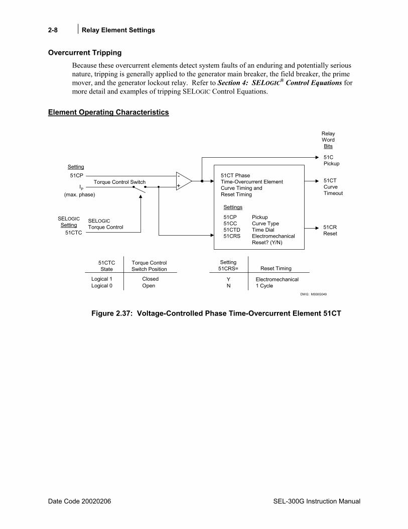
2-8 Relay Element Settings
Date Code 20020206 SEL-300G Instruction Manual
Overcurrent Tripping Because these overcurrent elements detect system faults of an enduring and potentially serious nature, tripping is generally applied to the generator main breaker, the field breaker, the prime mover, and the generator lockout relay. Refer to Section 4: SELOGIC® Control Equations for more detail and examples of tripping SELOGIC Control Equations.
Element Operating Characteristics
SELOGICTorque Control
51CTC51CRReset
51CTCurveTimeout
1 Cycle
Reset Timing
Electromechanical
Setting51CRS=
NY
Torque ControlSwitch Position
51CTCState
OpenClosed
Logical 0Logical 1
51CPickup
51CP Pickup51CC Curve Type51CTD Time Dial51CRS Electromechanical
Reset? (Y/N)
Settings
51CT PhaseTime-Overcurrent ElementCurve Timing andReset Timing(max. phase)
51CPTorque Control Switch
RelayWordBits
Setting
+-
IP
SELOGICSetting
DWG: M300G049
Figure 2.37: Voltage-Controlled Phase Time-Overcurrent Element 51CT
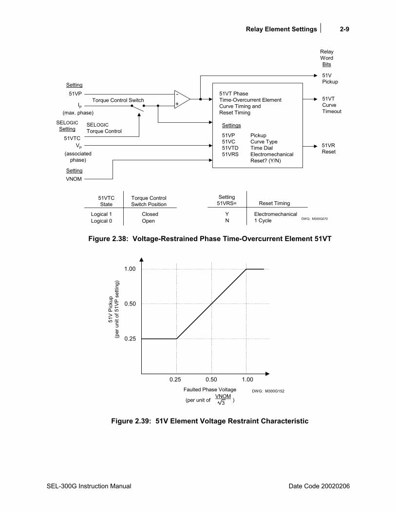
Relay Element Settings 2-9
SEL-300G Instruction Manual Date Code 20020206
SELOGICTorque Control
51VTC51VRReset
51VTCurveTimeout
1 Cycle
Reset Timing
Electromechanical
Setting51VRS=
NY
Torque ControlSwitch Position
51VTCState
OpenClosed
Logical 0Logical 1
51VPickup
51VP Pickup51VC Curve Type51VTD Time Dial51VRS Electromechanical
Reset? (Y/N)
Settings
51VT PhaseTime-Overcurrent ElementCurve Timing andReset Timing(max. phase)
51VPTorque Control Switch
RelayWordBits
Setting
+-
IP
SELOGICSetting
DWG: M300G070
VP
(associatedphase)
VNOMSetting
Figure 2.38: Voltage-Restrained Phase Time-Overcurrent Element 51VT
0.25
0.50
1.00
0.25 0.50 1.00
51V
Pick
up(p
er u
nit o
f 51V
P se
tting
)
Faulted Phase Voltage DWG: M300G152
(per unit of )VNOM
3
Figure 2.39: 51V Element Voltage Restraint Characteristic
2-10 Relay Element Settings
Date Code 20020206 SEL-300G Instruction Manual
OVER/UNDER VOLTAGE ELEMENTS
Element Description
Functional Description The SEL-300G Relay offers the following over- and undervoltage elements for protection, indication, and control functions.
• Two levels of phase undervoltage, 27P1 and 27P2
• Two levels of phase-to-phase undervoltage, 27PP1 and 27PP2
• One level of positive-sequence undervoltage, 27V1
• Two levels of phase overvoltage, 59P1 and 59P2
• Two levels of residual overvoltage, 59G1 and 59G2
• One level of negative-sequence overvoltage, 59Q
• One level of positive-sequence overvoltage, 59V1
• Two levels of phase-to-phase overvoltage, 59PP1 and 59PP2
Phase undervoltage elements operate using the minimum of the measured phase voltage magnitudes, operating if any single-phase measurement falls below the set threshold. The phase-to-phase undervoltage element operates using the minimum of the measured phase-to-phase voltages. The positive-sequence undervoltage element operates when the measured positive-sequence voltage falls below the set threshold.
Phase overvoltage elements operate using the maximum of the measured phase voltage magnitudes. Residual overvoltage elements operate using the sum of the three-phase voltage measurements. The positive- and negative-sequence overvoltage elements operate when their respective measurement exceeds their set threshold. The phase-to-phase overvoltage element operates when the maximum phase-to-phase voltage exceeds the set threshold.
Setting Descriptions Enable Undervoltage (U/V) Protection (Y, N) E27 = Y
Set E27 = Y to enable the 27P1, 27P2, 27PP, and 27V1 undervoltage elements. If none of these elements is required, set E27 = N. When E27 = N, the elements listed above are hidden and the pickup settings do not need to be entered.
Enable Overvoltage (O/V) Protection (Y, N) E59 = Y
Set E59 = Y to enable the 59P1, 59P2, 59G1, 59G2, 59Q, 59V1, and 59PP overvoltage elements. If none of these elements is required, set E59 = N. When E59 = N, the elements listed above are hidden and the pickup settings do not need to be entered.
Level 1 Phase U/V Pickup (OFF, 0.0200.0 V) 27P1P = 54.0
Level 2 Phase U/V Pickup (OFF, 0.0200.0 V) 27P2P = OFF
Pos.-Seq. U/V Pickup (OFF, 0.0200.0 V) 27V1P = OFF
Relay Element Settings 2-11
SEL-300G Instruction Manual Date Code 20020206
Level 1 Phase-to-Phase U/V Pickup (OFF, 0.0200.0 V) 27PP1 = 93.5
Level 2 Phase-to-Phase U/V Pickup (OFF, 0.0200.0 V) 27PP2 = 93.5
Level 1 Phase O/V Pickup (OFF, 0.0200.0 V) 59P1P = 74.0
Level 2 Phase O/V Pickup (OFF, 0.0200.0 V) 59P2P = OFF
Level 1 Residual O/V Pickup (OFF, 0.0200.0 V) 59G1P = 10.0
Level 2 Residual O/V Pickup (OFF, 0.0200.0 V) 59G2P = OFF
Neg.-Seq. O/V Pickup (OFF, 0.0200.0 V) 59QP = OFF
Pos.-Seq. U/V Pickup (OFF, 0.0200.0 V) 59V1P = OFF
Level 1 Phase-to-Phase O/V Pickup (OFF, 0.0200.0 V) 59PP1 = 128.2
Level 2 Phase-to-Phase O/V Pickup (OFF, 0.0200.0 V) 59PP2 = OFF
None of the elements is equipped with a definite-time delay. If a definite-time characteristic is desired, use a SELOGIC Control Equation variable and its built-in time-delay pickup and dropout timers.
Relay Word Bits
Relay Word Bit Function Description Typical Applications
27P1 Level 1 Phase Undervoltage Pickup Indication, Control
27P2 Level 2 Phase Undervoltage Pickup Indication, Control
27V1 Positive-Sequence Undervoltage Pickup Indication, Control
27PP1 Level 1 Phase-to-Phase Undervoltage Pickup Indication, Control
27PP2 Level 2 Phase-to-Phase Undervoltage Pickup Indication, Control
59P1 Level 1 Phase Overvoltage Pickup Indication, Control
59P2 Level 2 Phase Overvoltage Pickup Indication, Control
59G1 Level 1 Residual Overvoltage Pickup Indication, Control
59G2 Level 2 Residual Overvoltage Pickup Indication, Control
59Q Negative-Sequence Overvoltage Pickup Indication, Control
59V1 Positive-Sequence Overvoltage Pickup Indication, Control
59PP1 Level 1 Phase-to-Phase Overvoltage Pickup Indication, Control
59PP2 Level 2 Phase-to-Phase Overvoltage Pickup Indication, Control
Voltage Element Setting Calculation
Enable and apply those voltage elements that are required for your specific control scheme. Pickup settings and time delays are governed by the requirements of the application. Where specific elements typically are applied for torque control, setting guidelines have been provided in sections associated with the controlled element. Set the pickup of unused elements to OFF.
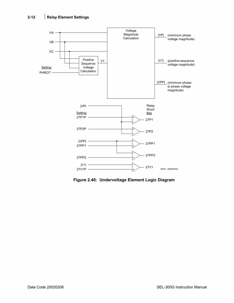
2-12 Relay Element Settings
Date Code 20020206 SEL-300G Instruction Manual
27V1P|V1|
27V1
27PP1|VPP|
27P2P
27P1P
|VP|
27PP1
27P2
27P1
VoltageMagnitudeCalculation
PositiveSequence
VoltageCalculationPHROT
VA
VB
VC
V1
|VP|
|V1|
|VPP|
(minimum phasevoltage magnitude)
(positive-sequencevoltage magnitude)
(minimum phase-to phase voltagemagnitude)
DWG: M300G052
Setting
Setting
RelayWordBits
+
_
+
_
27PP2 +
_27PP2
Figure 2.40: Undervoltage Element Logic Diagram
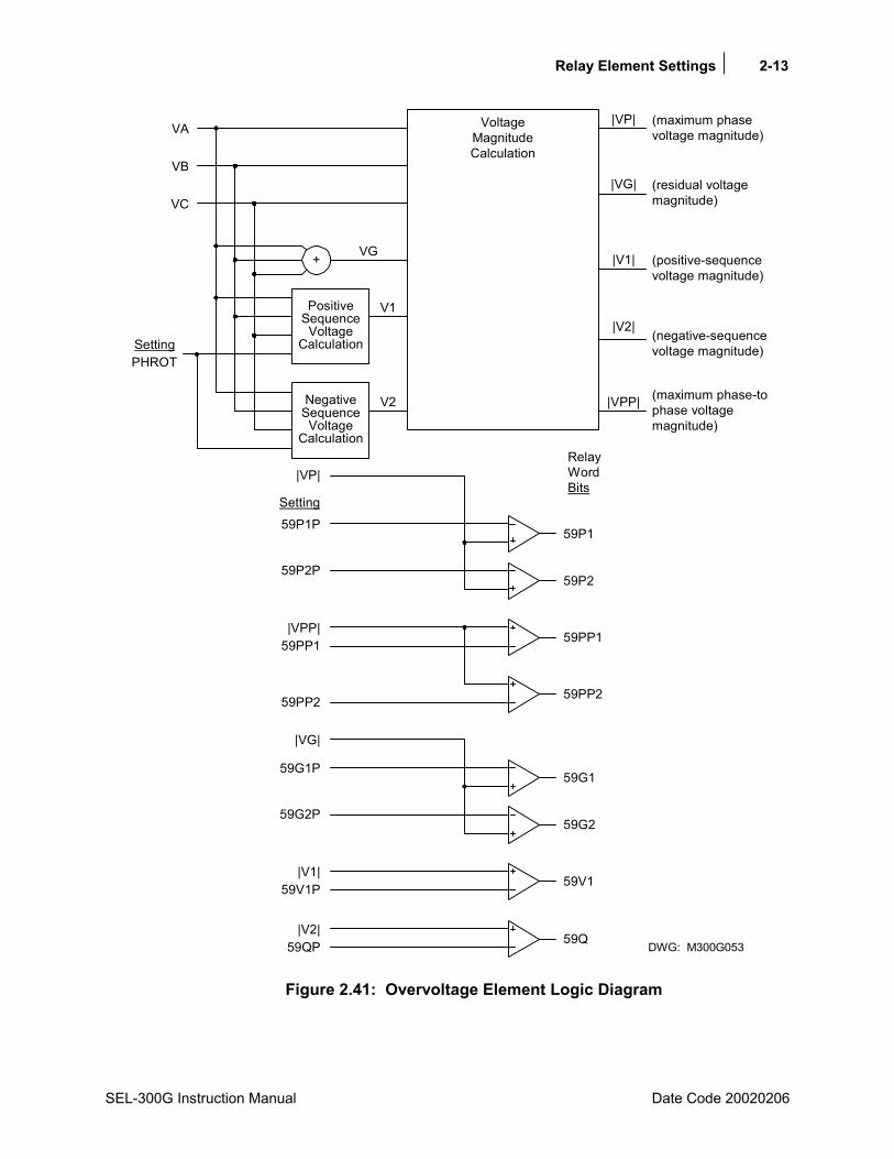
Relay Element Settings 2-13
SEL-300G Instruction Manual Date Code 20020206
59V1P|V1|
59G2P
59G1P
|VG|
59V1
59G2
59G1
59PP1|VPP|
59P2P
59P1P
|VP|
59PP1
59P2
59P1
VoltageMagnitudeCalculation
NegativeSequenceVoltage
Calculation
PositiveSequenceVoltage
Calculation
+
PHROT
VA
VB
VC
VG
V1
V2
|VP|
|VG|
|V1|
|V2|
|VPP|
(maximum phasevoltage magnitude)
(residual voltagemagnitude)
(positive-sequencevoltage magnitude)
(negative-sequencevoltage magnitude)
(maximum phase-tophase voltagemagnitude)
DWG: M300G053
Setting
RelayWordBits
Setting
59PP2 59PP2
59QP|V2|
59Q
Figure 2.41: Overvoltage Element Logic Diagram
2-14 Relay Element Settings
Date Code 20020206 SEL-300G Instruction Manual
LOSS-OF-POTENTIAL (60LOP) PROTECTION
Element Description
Functional Description The SEL-300G Relay provides an easy method to detect loss of relaying potential caused by blown potential fuses or operation of molded case circuit breakers in the potential circuit secondary. The relay declares a loss-of-potential if there is a 10% drop in the measured positive-sequence voltage with no corresponding change in positive-, negative-, or zero-sequence currents. If the condition persists for 60 cycles, it latches in. 60LOP resets when V1 returns to greater than 0.43 · VNOM, and V0 and V2 are both less than 5 V secondary.
Setting Descriptions
This function has no settings and is always active.
Relay Word Bits
Relay Word Bit Function Description Typical Applications
60LOP Loss of Relaying Potential Detected Indication, Control
100% STATOR GROUND PROTECTION ELEMENTS
Element Description
Functional Description The SEL-300G Relay provides a two-zone function designed to detect stator winding ground faults on resistance and high-impedance grounded generators. The Zone 1 element, 64G1, uses a fundamental-frequency neutral overvoltage element that is sensitive to faults in the middle and upper portions of the winding. The Zone 2 element, 64G2, uses a third-harmonic voltage differential function to detect faults in the upper and lower portions of the winding. By using the two zones together, the relay provides 100% stator ground fault coverage.
Note: Most generators produce enough third-harmonic voltage for proper application of the 64G2 element; however, some generators (e.g., those with 2/3 and 5/6 pitch windings) may not. In those cases the element based on the third-harmonic voltage, such as the 64G2, cannot be used for 100% Stator Ground Protection.
When a ground fault occurs high in the winding of a resistance or high-impedance grounded generator, a voltage appears at the generator neutral. The neutral voltage magnitude during the fault is proportional to the fault location within the winding. For instance, if a fault occurs 85% up the winding from the neutral point, the neutral voltage is 85% of the generator rated line-neutral voltage. The SEL-300G Relay asserts the 64G1 Relay Word bit when neutral voltage is greater than the 64G1P setting.
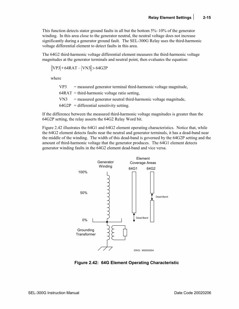
Relay Element Settings 2-15
SEL-300G Instruction Manual Date Code 20020206
This function detects stator ground faults in all but the bottom 5%10% of the generator winding. In this area close to the generator neutral, the neutral voltage does not increase significantly during a generator ground fault. The SEL-300G Relay uses the third-harmonic voltage differential element to detect faults in this area.
The 64G2 third-harmonic voltage differential element measures the third-harmonic voltage magnitudes at the generator terminals and neutral point, then evaluates the equation:
64G2PVN364RATVP3 >∗
where
VP3 = measured generator terminal third-harmonic voltage magnitude, 64RAT = third-harmonic voltage ratio setting, VN3 = measured generator neutral third-harmonic voltage magnitude, 64G2P = differential sensitivity setting.
If the difference between the measured third-harmonic voltage magnitudes is greater than the 64G2P setting, the relay asserts the 64G2 Relay Word bit.
Figure 2.42 illustrates the 64G1 and 64G2 element operating characteristics. Notice that, while the 64G2 element detects faults near the neutral and generator terminals, it has a dead-band near the middle of the winding. The width of this dead-band is governed by the 64G2P setting and the amount of third-harmonic voltage that the generator produces. The 64G1 element detects generator winding faults in the 64G2 element dead-band and vice versa.
DWG: M300G054
GroundingTransformer
0%
50%
100%
GeneratorWinding 64G1 64G2
ElementCoverage Areas
Dead-Band
Dead-Band
Figure 2.42: 64G Element Operating Characteristic
2-16 Relay Element Settings
Date Code 20020206 SEL-300G Instruction Manual
Typical generators produce varying amounts of third-harmonic voltage, depending on machine construction and loading. The magnitudes of terminal and neutral third-harmonic voltage may not be equal, and their rates of increase with increasing load may be different as well. The 64RAT setting is calculated to balance the voltage differential element performance over the range of machine loading. To properly set this element for an individual generator, it is necessary to operate the generator at full load and no load outputs, use the relay METER command to record the measured third-harmonic voltages, then calculate the settings. Full details of this procedure are provided below.
The Zone 2 stator ground element also may be applied as a neutral third-harmonic undervoltage element. When you set 64RAT = 0.0, the relay disables the third-harmonic voltage differential function. 64G2 acts as a neutral third-harmonic undervoltage element (27N3) with voltage pickup defined by 64G2P.
When open delta generator PTs are applied (DELTA_Y = D), the relay automatically uses neutral third-harmonic undervoltage protection.
Setting Descriptions Enable 100% Stator Ground Protection (Y, N) E64 = Y
Set E64 = Y to enable the 100% stator ground protection elements. If the relay is used to protect a solidly grounded machine, these elements are not effective and should be disabled by setting E64 = N. When E64 = N, the 64G1 and 64G2 elements are hidden and their settings do not need to be entered.
64G ELEMENT
Zone 1 Neutral O/V Pickup (OFF, 0.1150.0 V) 64G1P = 5.0
Zone 1 Time Delay (0.00400.00 s) 64G1D = 0.75
Zone 2 Differential Voltage (OFF, 0.120.0 V) 64G2P = 2.5
Zone 2 Ratio Setting (0.05.0) 64RAT = 1.0
Zone 2 Time Delay (0.00400.00 s) 64G2D = 0.08
64G Element Torque Control (SELOGIC Control Equation) 64GTC = 1
The 64G1P setting defines the sensitivity of the relay fundamental frequency neutral overvoltage element used to detect stator ground faults in the middle and upper areas of the generator winding. The 64G1D setting defines the Zone 1 element time delay.
The 64G2P setting defines the sensitivity of the relay third-harmonic voltage differential function used to detect stator ground faults in the lower and upper areas of the generator winding. The 64RAT setting defines a balancing ratio used to provide consistent element performance over the range of machine operation. The 64G2D setting defines the Zone 2 element time delay.
64RAT is hidden and set to 0.0 when setting DELTA_Y = D.
The 64GTC torque-control setting disables both zones when its result is logical 0. Both zones are enabled when the 64GTC result is logical 1.
Note: If 64G2 element is selected to operate in a differential mode, include !60LOP in the torque control equation 64GTC. This will avoid

Relay Element Settings 2-17
SEL-300G Instruction Manual Date Code 20020206
misoperation of the element during a loss-of-potential situation. However, if the 64G2 element is selected to operate as a neutral third-harmonic undervoltage element, do not include !60LOP in the torque control equation 64GTC.
Relay Word Bits
Relay Word Bit Function Description Typical Applications
64G1 Zone 1 Stator Ground Pickup Indication, Event Triggering, SER Triggering, Testing
64G1T Zone 1 Stator Ground Time-Delayed Trip Tripping, SER Triggering
64G2 Zone 2 Stator Ground Pickup Testing
64G2T Zone 2 Stator Ground Time-Delayed Trip Tripping, SER Triggering
100% Stator Ground Protection Setting Calculation
Information Needed
• Generator nominal voltage, VNOM
• Generator grounding transformer ratio to 1 (use 1 if machine is resistance grounded)
• Generator neutral voltage transformer ratio to 1 (use 1 if relay is connected directly to grounding transformer secondary winding)
• Generator neutral voltage during system ground fault (This voltage is caused by capacitive coupling in the generator step-up transformer. If this voltage is not known, coordination can be made on a time basis.)
• Relay settings PTR, PTRN, and DELTA_Y
Third-Harmonic Voltage Differential Setting Recommendations (four-wire potentials required)
The setting procedure below assists you in calculating 64G element settings that will offer secure, sensitive detection of stator winding faults. As described above, the 64G2 element characteristic has a midwinding dead-band whose width is governed by the 64G2P setting. The 64G1 neutral overvoltage element provides sensitive detection of stator faults in the dead-band when its settings are selected according to the following procedure.
Note: Perform the procedure when the relay is first installed, but after the generator being protected is connected to its step-up transformer or bus. Remove the 64G2T Relay Word bit from the relay tripping SELOGIC Control Equations. Use 64G1P = 5 V during the test. Set the balance of tripping functions according to the requirements of the particular generator. Leave these tripping functions in service to protect the generator in the event that a fault occurs during the test sequence.
2-18 Relay Element Settings
Date Code 20020206 SEL-300G Instruction Manual
To simplify the calculations below, you may wish to use the Microsoft® Excel spreadsheet, 64G Element Setting Worksheet, which is available on the SEL Internet home page at www.selinc.com or by contacting the factory.
1. Operate the generator at no load. Using the SEL-300G Relay METER command, record the values of terminal and neutral third-harmonic voltage.
primary kV load, no voltage,neutral harmonic-Third ______VN3_NLPprimary kV load, no voltage, terminalharmonic-Third______VP3_NLP
=
=
2. Increase the generator loading to 100%. Record the values of terminal and neutral third-harmonic voltage. Shut down the generator; the rest of this procedure does not require that the generator be in service.
primary. kV load, full voltage,neutral harmonic-_____ThirdVN3_FLPprimary. kV load, full voltage, terminalharmonic-_____ThirdVP3_FLP
=
=
3. Divide the primary third-harmonic voltage measurements by the relay PTR or PTRN settings to determine the secondary values.
V__________FL_3VNPTRN
FLP_3VNFL_3VN
V__________NL_3VNPTRN
NLP_3VNNL_3VN
V___________FL_3VPPTR
FLP_3VPFL_3VP
V___________NL_3VPPTR
VP3_NLPVP3_NL
=
=
=
=
=
=
=
=
4. Calculate the 64RAT setting using the following equation:
( )( )__________RAT64
VP3_NLVP3_FLVN3_NLVN3_FL64RAT
=++=
5. Calculate the minimum secure 64G2P setting using the equation:
( )volts___________64G2P
voltsFLVN3_VP3_FL64RAT0.11.164G2P
Min
Min
=
+=
This equation accounts for the maximum expected element error, plus adds an additional 5% measuring error to account for possible potential transformer errors.
Relay Element Settings 2-19
SEL-300G Instruction Manual Date Code 20020206
6. Calculate the low-winding coverage offered by these settings when the machine is operated at no load using the following equation:
( ) ( )%_______64G2
100%VN3_NLVP3_NL164RAT
64G2P164RAT
64RAT64G2
Min
Min
=
•
++−
+=
This value should be greater than 15% for most dependable stator ground protection.
7. Select a 64G1P setting that provides at least 10% overlap with the 64G2 element using the following equation:
VPTRN1.731000kV
100%10%%64G2
64G1P Min
−= secondary
Where kV = nominal machine line-to-line voltage, kV primary, PTRN = Ngt Nat, Ngt = grounding transformer ratio to 1 Nat = auxiliary transformer ratio to 1, use 1 if relay VN input is connected directly
to the grounding transformer secondary.
64G1P must be greater than 0.5 V secondary. Zero-sequence voltage can appear across the grounding transformer secondary during a system ground fault due to capacitive coupling between the windings of the unit transformer. If 64G1P is less than the zero-sequence voltage, then the 64G1D setting must be longer than system ground fault clearing time to provide security.
Third-Harmonic Neutral Undervoltage Setting Recommendations (use with open-delta potentials)
The vast majority of generator protection applications will benefit from the improved ground fault sensitivity offered by the third-harmonic voltage differential protection scheme described above. In the event that your protection standards require third-harmonic neutral undervoltage protection, use the following setting procedure to define the protection settings.
Note: Perform the procedure when the relay is first installed, but after the generator being protected is connected to its step-up transformer or bus. Remove the 64G2T Relay Word bit from the relay tripping SELOGIC Control Equations. Use 64G1P = 5 V during the test. Set the balance of tripping functions according to the requirements of the particular generator. Leave these tripping functions in service to protect the generator in the event that a fault occurs during the test sequence.
1. Operate the generator at no load. Using the SEL-300G Relay METER command, record the values of neutral third-harmonic voltage.
load. no voltage,neutral harmonic-d______ThirVN3_NLP =

2-20 Relay Element Settings
Date Code 20020206 SEL-300G Instruction Manual
2. Operate the generator at full load. Using the SEL-300G Relay METER command, record the value of neutral third-harmonic voltage. Shut down the generator; the rest of this procedure does not require that the generator be in service.
load. full voltage,neutral harmonic_____ThirdVN3_FLP −=
3. Divide the primary third-harmonic voltage measurements by the relay PTRN setting to determine the secondary values. Note that VN3_FL is calculated for record only and is not used in setting the 64G2 element.
V___________FL_3VNPTRN
VN3_FLPFL_3VN
V___________NL_3VNPTRN
VN3_NLPVN3_NL
=
=
=
=
4. Set the 64RAT setting equal to 0.0 to disable third-harmonic voltage differential protection and enable third-harmonic neutral undervoltage protection. The relay does this automatically and hides the 64RAT setting if DELTA_Y = D.
0.064RAT =
5. Set the 64G2P setting approximately 50% of the generator no load third-harmonic neutral voltage:
secondary V__________64G2Psecondary V VN3_NL0.564G2P
=
=
6. It is not possible to calculate the low-winding coverage offered by this setting because the third-harmonic terminal voltages are not available.
7. Select 64G1P to detect faults in the top 95-98% of the generator winding by using the following equation:
−=PTRN1.7321000kV
100Coverage %164G1P
Where %Coverage = Desired % coverage kV = nominal machine line-to-line voltage, kV primary PTRN = Ngt Nat Ngt = grounding transformer ratio to 1 Nat = neutral voltage auxiliary transformer ration to 1, use 1 if relay VN
input is connected directly to the grounding transformer secondary.
64G1P must be greater than 0.5 V secondary. Zero-sequence voltage can appear across the grounding transformer secondary during a system ground fault due to capacitive coupling between the windings of the unit transformer. If 64G1P is less than the zero-sequence voltage, then the 64G1D setting must be longer than system ground fault clearing time to provide security.
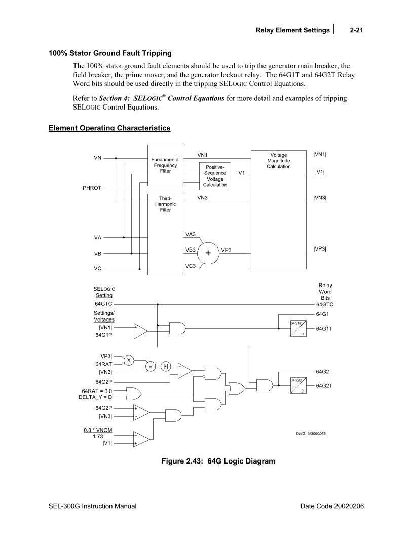
Relay Element Settings 2-21
SEL-300G Instruction Manual Date Code 20020206
100% Stator Ground Fault Tripping The 100% stator ground fault elements should be used to trip the generator main breaker, the field breaker, the prime mover, and the generator lockout relay. The 64G1T and 64G2T Relay Word bits should be used directly in the tripping SELOGIC Control Equations.
Refer to Section 4: SELOGIC® Control Equations for more detail and examples of tripping SELOGIC Control Equations.
Element Operating Characteristics
64G2P
|VN3|
|VN1|
64G2T
64G1T
VoltageMagnitudeCalculation
VP3
|VN1|
|VN3|
|VP3|
DWG: M300G055
+
VA3
VC3
VB3
Third-Harmonic
Filter
VA
VC
VB
FundamentalFrequency
Filter
VN3
VN1VN
64G1D
0
64G1
64G1P
64G2D
0
-X
64G2
|VP3|64RAT
Positive-Sequence
VoltageCalculationPHROT
V1
64GTC
64RAT = 0.0
-
+
|VN3|64G2P
+
_0.8 * VNOM1.73
|V1|
|V1|
SELOGICSetting
Settings/Voltages
RelayWordBits
||
64GTC
DELTA_Y = D
Figure 2.43: 64G Logic Diagram
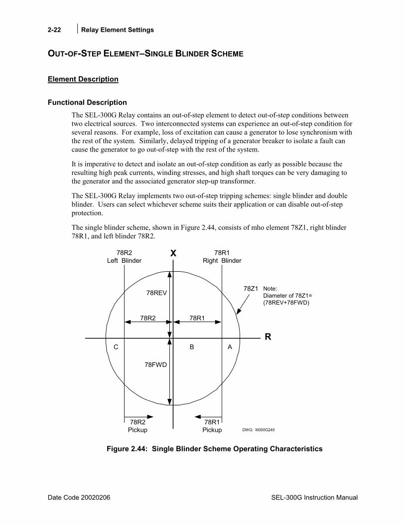
2-22 Relay Element Settings
Date Code 20020206 SEL-300G Instruction Manual
OUT-OF-STEP ELEMENTSINGLE BLINDER SCHEME
Element Description
Functional Description The SEL-300G Relay contains an out-of-step element to detect out-of-step conditions between two electrical sources. Two interconnected systems can experience an out-of-step condition for several reasons. For example, loss of excitation can cause a generator to lose synchronism with the rest of the system. Similarly, delayed tripping of a generator breaker to isolate a fault can cause the generator to go out-of-step with the rest of the system.
It is imperative to detect and isolate an out-of-step condition as early as possible because the resulting high peak currents, winding stresses, and high shaft torques can be very damaging to the generator and the associated generator step-up transformer.
The SEL-300G Relay implements two out-of-step tripping schemes: single blinder and double blinder. Users can select whichever scheme suits their application or can disable out-of-step protection.
The single blinder scheme, shown in Figure 2.44, consists of mho element 78Z1, right blinder 78R1, and left blinder 78R2.
B
X
R
78REV
78FWD
78Z1
78R2Left Blinder
DWG: M300G245
78R2 78R1
78R1Right Blinder
AC
78R2Pickup
78R1Pickup
Note:Diameter of 78Z1=(78REV+78FWD)
Figure 2.44: Single Blinder Scheme Operating Characteristics
Relay Element Settings 2-23
SEL-300G Instruction Manual Date Code 20020206
This scheme detects an out-of-step condition by tracking the path of positive-sequence impedance trajectories that pass through the protection zone. If the relay detects an out-of-step condition, it asserts the following Relay Word bits:
• Relay Word bit SWING picks up when the positive-sequence impedance moves from the load region into Area A (left blinder 78R2 and mho element 78Z1 assert).
• Relay Word bit OOS picks up when the impedance trajectory advances further to Area B between the two blinders (right blinder 78R1, left blinder 78R2, and mho element 78Z1 assert).
• At the time the impedance trajectory exits the mho circle via Area C, the rising-edge triggered timer with 78TD pickup delay and 78TDURD dropout-delay starts timing. Relay Word bit OOST remains picked up for 78TDURD seconds after the pickup delay time 78TD expires.
• The above description is only for trajectories traveling from right to left. Out-of-step trajectories traveling from left to right traverse the protection zone in the reverse sequence (i.e., from Area C to B to A). The Relay Word bits assert in the same way whether trajectories travel from right to left or from left to right.
The single blinder scheme distinguishes between short circuit faults and out-of-step conditions by tracking the path of the impedance trajectory. During short circuit faults, the impedance will move from the load region to inside the mho element and between the two blinders almost instantaneously preventing the out-of-step function from picking up.
Figure 2.45 shows the logic diagram for the single blinder scheme.

2-24 Relay Element Settings
Date Code 20020206 SEL-300G Instruction Manual
78R
2
78Z1
50AB
C
0.5
CYC
*
0
0.5
CYC
*
0
_+ _+
78R
1R
eZ1
0.5
CYC
*
0
Latc
h th
e st
ates
of 7
8R1
and
78R
2on
risi
ng e
dge
of S
WIN
G
OO
S
Rel
a yW
ord
Bits
78R
178
R2
SWIN
G
1La
tche
d 78
R1
Latc
hed
78R
21
OO
STC
78TD
78TD
UR
D
OO
ST
1
Inpu
t
Out
put DW
G: M
300G
234
Setti
ngs
*Hal
f-Cyc
le P
roce
ssin
g In
terv
al
78TD
78TD
UR
D
_+
|I1|
00.
5C
YC*
SELO
GIC
Setti
ngs
Figure 2.45: Single Blinder Scheme Logic Diagram
Relay Element Settings 2-25
SEL-300G Instruction Manual Date Code 20020206
Setting Descriptions Enable Out-of-Step Protection (1B, 2B, N) E78 = 1B
Set E78 = 1B or 2B to enable out-of-step protection elements. If out-of-step protection is not required, set E78 = N. E78 = 1B requires the following entries:
Forward Reach Reactance (0.1100.0 Ohms) 78FWD = 8.0
Reverse Reach Reactance (0.1100.0 Ohms) 78REV = 8.0
Right Blinder (0.150.0 Ohms) 78R1 = 6.0
Left Blinder (0.150.0 Ohms) 78R2 = 6.0
Out-of-Step Trip Delay (0.001.00 seconds) 78TD = 0.00
Out-of-Step Trip Duration (0.005.00 seconds) 78TDURD = 3.00
Pos.-Seq. Current Supervision (0.2530.00 Amps) 50ABC = 0.25
78 Element Torque Control (SELOGIC Control Equation) OOSTC = 1
Notes: The values indicated above are default settings for a 5 A relay. For a 1 A relay, multiply ohms by five and divide amperes by five.
The sum of the forward and reverse reaches (the diameter of the mho circle) has to be 100 ohms or less for a 5 A relay and 500 ohms or less for a 1 A relay. The blinder settings must be greater than or equal to five percent of either the forward or the reverse reach, whichever is greater. The 78 Element Torque Control SELOGIC Control Equation OOSTC has a default setting of one. If this value is left at one, the out-of-step element will not be controlled by any other conditions external to the element. However, users can block the operation of the 78 element for certain conditions, such as the presence of excessive negative-sequence currents, by setting OOSTC to !46Q1. Refer to Section 4: SELOGIC® Control Equations for a detailed discussion of SELOGIC Control Equations. The trip delay timer also has an adjustable dropout delay 78TDURD (Trip Duration). The 78TDURD should be set appropriately if the Relay Word bit OOST is configured to operate an output contact directly, instead of being routed through the common trip logic. Default setting for the 78TDURD is three seconds. However, if Relay Word bit OOST is in SELOGIC trip equations TR1 through TR4, set 78TDURD to zero seconds because the common trip logic has an identical timer, TDURD. Refer to Section 4: SELOGIC® Control Equations for details regarding trip logic. The scheme includes positive-sequence current supervision setting 50ABC, which has a setting range of 0.2530.00 A for 5 A relays and 0.056.00 A for 1 A relays. Normally, a setting of 0.25 A for 5 A relays is adequate for most applications. However, a higher setting can be applied based on minimum expected swing currents. Note that the positive-sequence current levels below the 50ABC setting will block the out-of-step function. Both 78R1 and 78R2 must be within the mho circle.
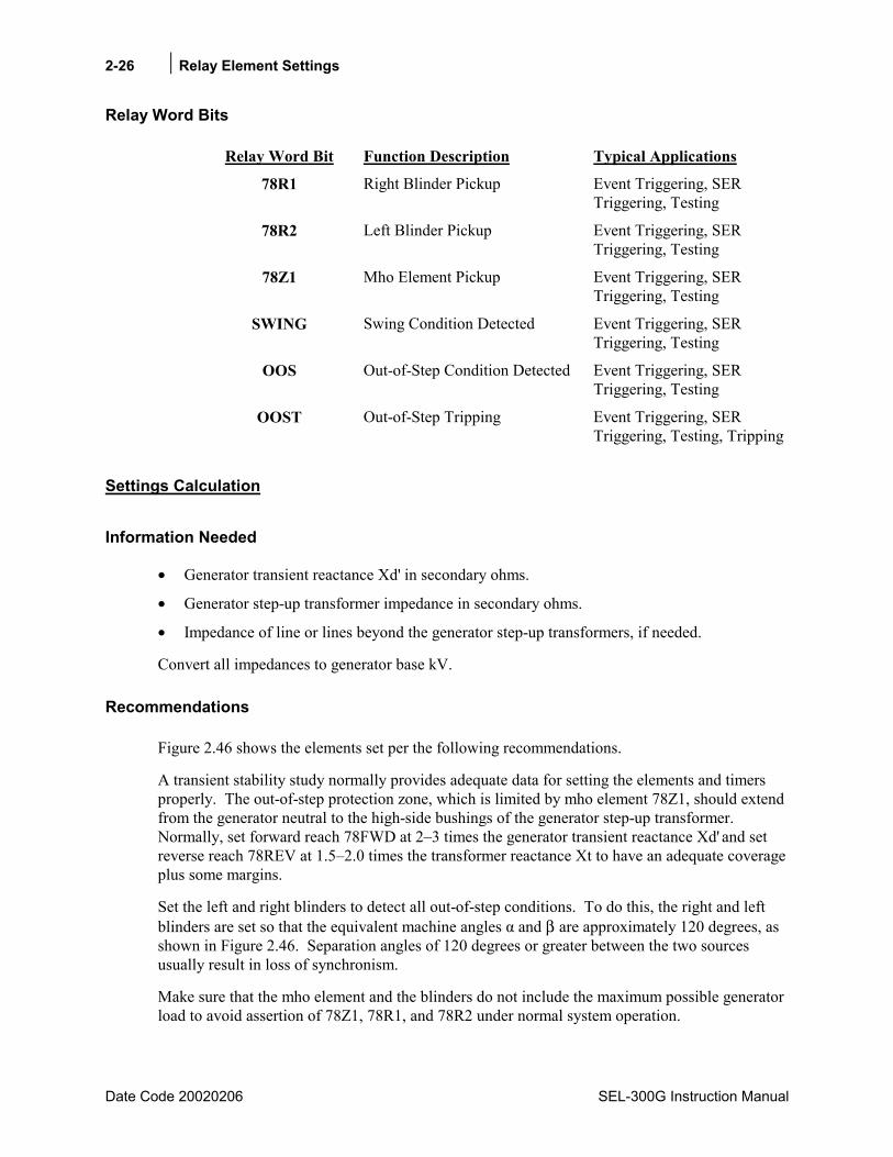
2-26 Relay Element Settings
Date Code 20020206 SEL-300G Instruction Manual
Relay Word Bits
Relay Word Bit Function Description Typical Applications
78R1 Right Blinder Pickup Event Triggering, SER Triggering, Testing
78R2 Left Blinder Pickup Event Triggering, SER Triggering, Testing
78Z1 Mho Element Pickup Event Triggering, SER Triggering, Testing
SWING Swing Condition Detected Event Triggering, SER Triggering, Testing
OOS Out-of-Step Condition Detected Event Triggering, SER Triggering, Testing
OOST Out-of-Step Tripping Event Triggering, SER Triggering, Testing, Tripping
Settings Calculation
Information Needed
• Generator transient reactance Xd' in secondary ohms.
• Generator step-up transformer impedance in secondary ohms.
• Impedance of line or lines beyond the generator step-up transformers, if needed.
Convert all impedances to generator base kV.
Recommendations
Figure 2.46 shows the elements set per the following recommendations.
A transient stability study normally provides adequate data for setting the elements and timers properly. The out-of-step protection zone, which is limited by mho element 78Z1, should extend from the generator neutral to the high-side bushings of the generator step-up transformer. Normally, set forward reach 78FWD at 23 times the generator transient reactance Xd' and set reverse reach 78REV at 1.52.0 times the transformer reactance Xt to have an adequate coverage plus some margins.
Set the left and right blinders to detect all out-of-step conditions. To do this, the right and left blinders are set so that the equivalent machine angles α and β are approximately 120 degrees, as shown in Figure 2.46. Separation angles of 120 degrees or greater between the two sources usually result in loss of synchronism.
Make sure that the mho element and the blinders do not include the maximum possible generator load to avoid assertion of 78Z1, 78R1, and 78R2 under normal system operation.
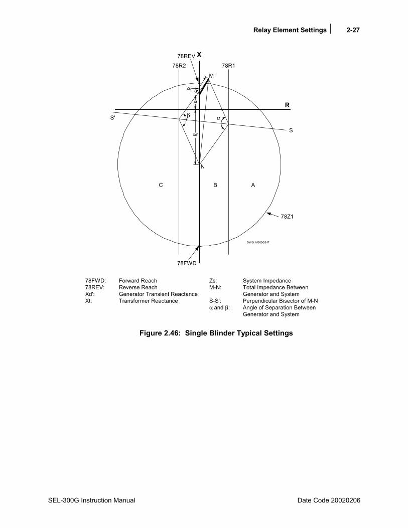
Relay Element Settings 2-27
SEL-300G Instruction Manual Date Code 20020206
DWG: M300G247
R
S
S'
ABC
M
N
78R278REV
78R1
β α
78FWD
78FWD: Forward Reach78REV: Reverse ReachXd': Generator Transient ReactanceXt: Transformer Reactance
Zs: System ImpedanceM-N: Total Impedance Between
Generator and SystemS-S': Perpendicular Bisector of M-Nα and β: Angle of Separation Between
Generator and System
Zs
Xd'
X
78Z1
Xt
Figure 2.46: Single Blinder Typical Settings

2-28 Relay Element Settings
Date Code 20020206 SEL-300G Instruction Manual
OUT-OF-STEP ELEMENTDOUBLE BLINDER SCHEME
Element Description
Functional Description The SEL-300G Relay contains an out-of-step element to detect out-of-step conditions between two electrical sources. Two interconnected systems can experience an out-of-step condition for several reasons. For example, loss of excitation can cause a generator to lose synchronism with the rest of the system. Similarly, delayed tripping of a generator breaker to isolate a fault can cause the generator to go out-of-step with the rest of the system.
It is imperative to detect and isolate an out-of-step condition as early as possible because the resulting high peak currents, winding stresses, and high shaft torques can be very damaging to the generator and the associated generator step-up transformer.
The SEL-300G Relay implements two out-of-step tripping schemes: single blinder and double blinder. Users can select whichever scheme suits their application, or can disable out-of-step protection.
78R178R2 78R2
X
R
78Z1
78R1
DWG: M300G246
78REV
78FWD
78R2
78R1
78R1Pickup
78R2Pickup
78R2Pickup
78R1Pickup
Note:Diameter of 78Z1=(78REV+78FWD)
Figure 2.47: Double Blinder Scheme Operating Characteristics
The double blinder scheme, shown in Figure 2.47, consists of mho element 78Z1 and two blinder pairs: outer resistance blinder 78R1 and inner resistance blinder 78R2. This scheme uses timer 78D as part of its logic to detect out-of-step conditions. The scheme declares an out-of-step condition if the positive-sequence impedance stays between the two blinders for more than 78D

Relay Element Settings 2-29
SEL-300G Instruction Manual Date Code 20020206
seconds and advances further inside the inner blinder. The logic issues an out-of-step trip once an out-of-step condition is established and the positive-sequence impedance exits the mho circle.
If the relay detects an out-of-step condition, it asserts the following Relay Word bits:
• Relay Word bit SWING picks up when the positive-sequence impedance stays between the outer and inner blinders for more than 78D seconds (78R1 asserts, mho element 78Z1 may or may not assert).
• Relay Word bit OOS picks up when the impedance trajectory advances further inside the inner blinder (78R1, 78R2, and mho element 78Z1 assert).
• At the time the impedance trajectory exits the mho circle, the rising-edge triggered timer with 78TD pickup delay and 78TDURD dropout delay starts timing. Relay Word bit OOST remains picked up for 78TDURD seconds after pickup delay time 78TD expires.
The double blinder scheme distinguishes between short circuit faults and out-of-step conditions by monitoring the length of time that the impedance trajectory stays between the two blinders. During short circuit faults, the impedance either moves inside the inner blinder or goes through the two blinders almost instantaneously so the 78D does not time out. Either case prevents the out-of-step element from picking up.
Figure 2.48 shows the logic diagram for the double blinder scheme.
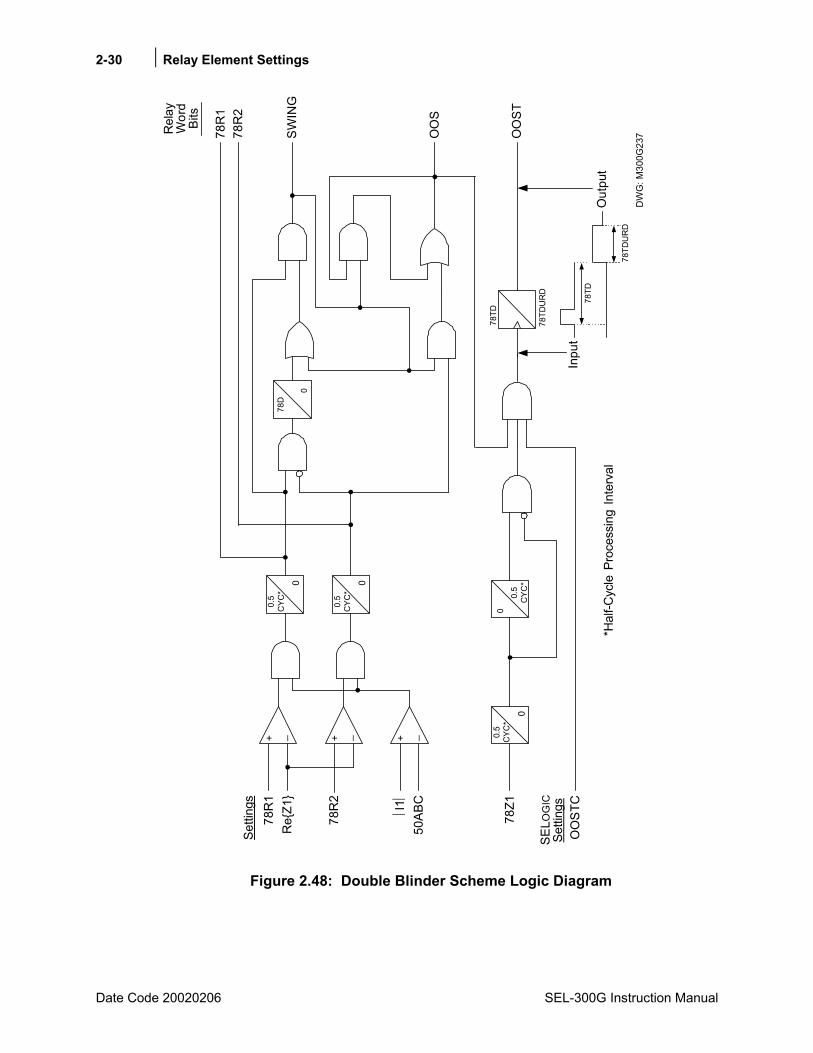
2-30 Relay Element Settings
Date Code 20020206 SEL-300G Instruction Manual
_+ _+ _+
78R
1R
eZ1
78R
2
I1
50AB
CO
OS
Rel
ayW
ord
Bits
78R
178
R2
SWIN
G
DW
G: M
300G
237
Setti
ngs
0.5
CYC
*
0
078
Z1
OO
STC
78TD
78TD
UR
D
OO
ST
78D
0
*Hal
f-Cyc
le P
roce
ssin
g In
terv
al
Inpu
t
Out
put
78TD
78TD
UR
D
0.5
CYC
*
0
0.5
CYC
*
0
0.5
CYC
*
SELO
GIC
Setti
ngs
Figure 2.48: Double Blinder Scheme Logic Diagram
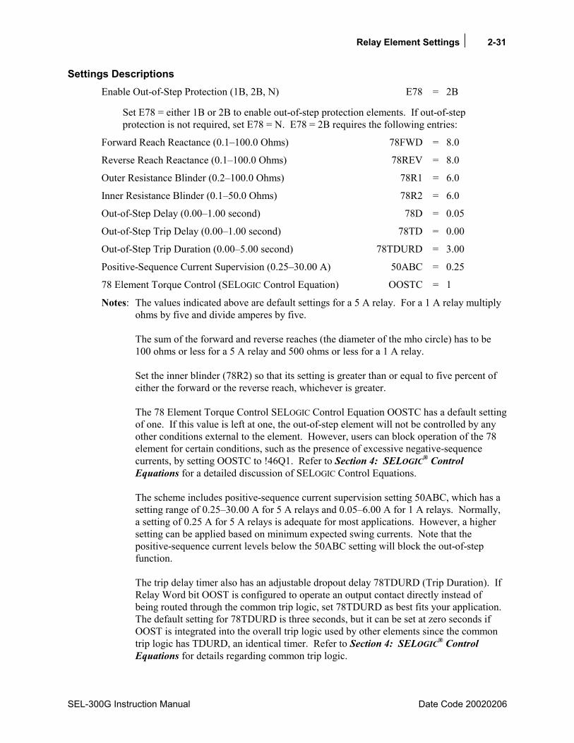
Relay Element Settings 2-31
SEL-300G Instruction Manual Date Code 20020206
Settings Descriptions Enable Out-of-Step Protection (1B, 2B, N) E78 = 2B
Set E78 = either 1B or 2B to enable out-of-step protection elements. If out-of-step protection is not required, set E78 = N. E78 = 2B requires the following entries:
Forward Reach Reactance (0.1100.0 Ohms) 78FWD = 8.0
Reverse Reach Reactance (0.1100.0 Ohms) 78REV = 8.0
Outer Resistance Blinder (0.2100.0 Ohms) 78R1 = 6.0
Inner Resistance Blinder (0.150.0 Ohms) 78R2 = 6.0
Out-of-Step Delay (0.001.00 second) 78D = 0.05
Out-of-Step Trip Delay (0.001.00 second) 78TD = 0.00
Out-of-Step Trip Duration (0.005.00 second) 78TDURD = 3.00
Positive-Sequence Current Supervision (0.2530.00 A) 50ABC = 0.25
78 Element Torque Control (SELOGIC Control Equation) OOSTC = 1
Notes: The values indicated above are default settings for a 5 A relay. For a 1 A relay multiply ohms by five and divide amperes by five. The sum of the forward and reverse reaches (the diameter of the mho circle) has to be 100 ohms or less for a 5 A relay and 500 ohms or less for a 1 A relay. Set the inner blinder (78R2) so that its setting is greater than or equal to five percent of either the forward or the reverse reach, whichever is greater. The 78 Element Torque Control SELOGIC Control Equation OOSTC has a default setting of one. If this value is left at one, the out-of-step element will not be controlled by any other conditions external to the element. However, users can block operation of the 78 element for certain conditions, such as the presence of excessive negative-sequence currents, by setting OOSTC to !46Q1. Refer to Section 4: SELOGIC® Control Equations for a detailed discussion of SELOGIC Control Equations. The scheme includes positive-sequence current supervision setting 50ABC, which has a setting range of 0.2530.00 A for 5 A relays and 0.056.00 A for 1 A relays. Normally, a setting of 0.25 A for 5 A relays is adequate for most applications. However, a higher setting can be applied based on minimum expected swing currents. Note that the positive-sequence current levels below the 50ABC setting will block the out-of-step function. The trip delay timer also has an adjustable dropout delay 78TDURD (Trip Duration). If Relay Word bit OOST is configured to operate an output contact directly instead of being routed through the common trip logic, set 78TDURD as best fits your application. The default setting for 78TDURD is three seconds, but it can be set at zero seconds if OOST is integrated into the overall trip logic used by other elements since the common trip logic has TDURD, an identical timer. Refer to Section 4: SELOGIC® Control Equations for details regarding common trip logic.
2-32 Relay Element Settings
Date Code 20020206 SEL-300G Instruction Manual
The inner resistance blinder must be inside the mho circle while the outer resistance blinder should be outside the mho circle for the logic to operate correctly.
Relay Word Bits
Relay Word Bit Function Description Typical Applications
78R1 Outer Resistance Blinder Pickup Event Triggering, SER Triggering, Testing
78R2 Inner Resistance Blinder Pickup Event Triggering, SER Triggering, Testing
78Z1 Mho Element Pickup Event Triggering, SER Triggering, Testing
SWING Swing Condition Detected Event Triggering, SER Triggering, Testing
OOS Out-of-Step Condition Detected Event Triggering, SER Triggering, Testing
OOST Out-of-Step Tripping Event Triggering, SER Triggering, Testing, Tripping
Settings Calculation
Information Needed
• Generator transient reactance, Xd' in secondary ohms.
• Generator step-up transformer impedance in secondary ohms.
• Impedance of line or lines beyond the generator step-up transformers, if needed.
Convert all impedances to generator base kV.
Recommendations
Figure 2.49 shows the elements set per the following recommendations.
The out-of-step protection zone, which is limited by mho element 78Z1, should extend from the generator neutral to the high-side bushings of the generator step-up transformer. Normally, the forward reach 78FWD of the mho element is set at 23 times the generator transient reactance Xd' and its reverse reach 78REV at 1.52 times the transformer reactance Xt. These settings for the forward and the reverse reach will provide adequate coverage plus some margin. Refer to Figure 2.49 for details.
Set the inner blinder 78R2 to detect all out-of-step conditions. To do this, set the inner blinder so that the equivalent machine angles α, shown in Figure 2.49, is approximately 120 degrees. A separation angle of 120 degrees or greater between two sources will generally result in loss of synchronism.

Relay Element Settings 2-33
SEL-300G Instruction Manual Date Code 20020206
The outer blinder 78R1 and out-of-step timer 78D should be set to satisfy the following:
• The outer blinder should not assert on maximum load.
• The outer blinder should lie outside the mho circle to satisfy the relay logic.
• The outer blinder should separate from the inner blinder far enough to ensure that the 78D timer accurately times the out-of-step slip cycle.
The SEL-300G Relay processes the out-of-step logic every one-half cycle of the system frequency. To ensure that the relay times the out-of-step slip frequency accurately, the outer and inner blinders must be separated appropriately. For example, assume that the highest out-of-step frequency encountered is five slip cycles per second, which translates to 30 degrees per cycle (60 Hz). Set the blinders with a 70-degree separation. This separation translates to a positive-sequence impedance travel time of 2.3 cycles between the two blinders, which should provide adequate timing accuracy. Set the 78D timer at approximately 0.034 seconds (two cycles), which ensures that 78D will pickup for swings traveling at 30 degrees per cycle or less.
The out-of-step slip frequency is a system-specific value. A transient stability study normally determines this variable and therefore the double blinder settings.
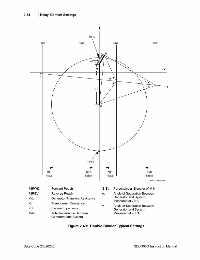
2-34 Relay Element Settings
Date Code 20020206 SEL-300G Instruction Manual
78FWD: Forward Reach78REV: Reverse ReachX'd: Generator Transient ReactanceXt: Transformer ReactanceZS: System ImpedanceM-N: Total Impedance Between
Generator and System
S-S': Perpendicular Bisector of M-Nα: Angle of Separation Between
Generator and SystemMeasured at 78R2
γ: Angle of Separation BetweenGenerator and SystemMeasured at 78R1
78REV
–78R1 –78R2 78R2 78R1
78FWD
αγ
S'
RRRR
S
N
Zs
DWG: M300G248b
Xt
Xd'
M
XXXX
78R2Pickup
78R1Pickup
78R1Pickup
78R2Pickup
Figure 2.49: Double Blinder Typical Settings
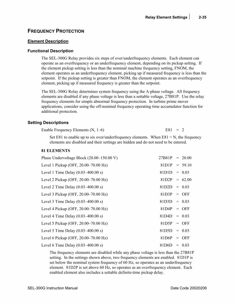
Relay Element Settings 2-35
SEL-300G Instruction Manual Date Code 20020206
FREQUENCY PROTECTION
Element Description
Functional Description The SEL-300G Relay provides six steps of over/underfrequency elements. Each element can operate as an overfrequency or an underfrequency element, depending on its pickup setting. If the element pickup setting is less than the nominal machine frequency setting, FNOM, the element operates as an underfrequency element, picking up if measured frequency is less than the setpoint. If the pickup setting is greater than FNOM, the element operates as an overfrequency element, picking up if measured frequency is greater than the setpoint.
The SEL-300G Relay determines system frequency using the A-phase voltage. All frequency elements are disabled if any phase voltage is less than a settable voltage, 27B81P. Use the relay frequency elements for simple abnormal frequency protection. In turbine prime mover applications, consider using the off-nominal frequency operating time accumulator function for additional protection.
Setting Descriptions Enable Frequency Elements (N, 16) E81 = 2
Set E81 to enable up to six over/underfrequency elements. When E81 = N, the frequency elements are disabled and their settings are hidden and do not need to be entered.
81 ELEMENTS
Phase Undervoltage Block (20.00150.00 V) 27B81P = 20.00
Level 1 Pickup (OFF, 20.0070.00 Hz) 81D1P = 59.10
Level 1 Time Delay (0.03400.00 s) 81D1D = 0.03
Level 2 Pickup (OFF, 20.0070.00 Hz) 81D2P = 62.00
Level 2 Time Delay (0.03400.00 s) 81D2D = 0.03
Level 3 Pickup (OFF, 20.0070.00 Hz) 81D3P = OFF
Level 3 Time Delay (0.03400.00 s) 81D3D = 0.03
Level 4 Pickup (OFF, 20.0070.00 Hz) 81D4P = OFF
Level 4 Time Delay (0.03400.00 s) 81D4D = 0.03
Level 5 Pickup (OFF, 20.0070.00 Hz) 81D5P = OFF
Level 5 Time Delay (0.03400.00 s) 81D5D = 0.03
Level 6 Pickup (OFF, 20.0070.00 Hz) 81D6P = OFF
Level 6 Time Delay (0.03400.00 s) 81D6D = 0.03
The frequency elements are disabled while any phase voltage is less than the 27B81P setting. In the settings shown above, two frequency elements are enabled. 81D1P is set below the nominal system frequency of 60 Hz, so operates as an underfrequency element. 81D2P is set above 60 Hz, so operates as an overfrequency element. Each enabled element also includes a settable definite-time pickup delay.

2-36 Relay Element Settings
Date Code 20020206 SEL-300G Instruction Manual
Relay Word Bits
Relay Word Bit Function Description Typical Applications
81D1 Level 1 Frequency Element Pickup Testing
81D1T Level 1 Frequency Element With Time Delay Tripping, Indication, SER Triggering
81D2 Level 2 Frequency Element Pickup Testing
81D2T Level 2 Frequency Element With Time Delay Tripping, Indication, SER Triggering
81D3 Level 3 Frequency Element Pickup Testing
81D3T Level 3 Frequency Element With Time Delay Tripping, Indication, SER Triggering
81D4 Level 4 Frequency Element Pickup Testing
81D4T Level 4 Frequency Element With Time Delay Tripping, Indication, SER Triggering
81D5 Level 5 Frequency Element Pickup Testing
81D5T Level 5 Frequency Element With Time Delay Tripping, Indication, SER Triggering
81D6 Level 6 Frequency Element Pickup Testing
81D6T Level 6 Frequency Element With Time Delay Tripping, Indication, SER Triggering
27B81 Phase Undervoltage for Frequency Element Blocking
Indication, Event Triggering, Testing
Note: Instantaneous frequency element Relay Word bits 81D181D6 should not be used for applications other than testing.
Frequency Element Setting Calculation
Information Needed
• Required or desired abnormal frequency protection tripping frequencies and delays
• Generator over/underfrequency shedding frequencies and delays
Recommendations Enable the required number of over/underfrequency elements for your application. Your generator prime mover manufacturer can provide abnormal frequency tripping guidelines to protect the generator and prime mover. Your local system coordinating council may have published underfrequency load shedding requirements. A 20V setting for 27B81P provides frequency element operation over the widest range of system and generator voltages.
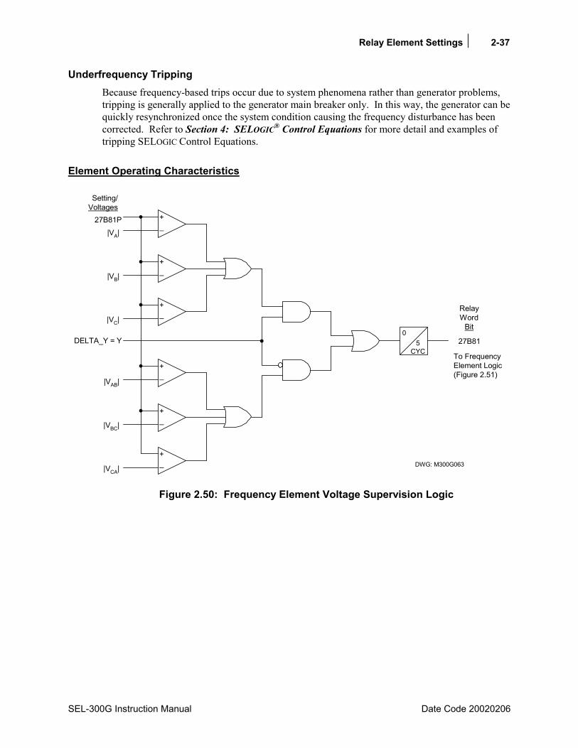
Relay Element Settings 2-37
SEL-300G Instruction Manual Date Code 20020206
Underfrequency Tripping Because frequency-based trips occur due to system phenomena rather than generator problems, tripping is generally applied to the generator main breaker only. In this way, the generator can be quickly resynchronized once the system condition causing the frequency disturbance has been corrected. Refer to Section 4: SELOGIC® Control Equations for more detail and examples of tripping SELOGIC Control Equations.
Element Operating Characteristics
To FrequencyElement Logic(Figure 2.51)
|VA|27B81P
Setting/Voltages
27B81
RelayWord
Bit
DWG: M300G063
|VB|
|VC|
_+
_+
_+
05
CYC
|VAB|
|VBC|
|VCA|
_+
_+
_+
DELTA_Y = Y
Figure 2.50: Frequency Element Voltage Supervision Logic

2-38 Relay Element Settings
Date Code 20020206 SEL-300G Instruction Manual
_+
81D1D
0
_+
Over-Frequency
Under-Frequency
81D1*
81D1T
81D1P
81D1P FNOM
81D1P FNOM
FrequencyElement 1(SettingE81 1)
_+
81D2D
0
_+
Over-Frequency
Under-Frequency
81D2*
81D2T
81D2P
81D2P FNOM
81D2P FNOM
FrequencyElement 2(SettingE81 2)
_+
81D3D
0
_+
Over-Frequency
Under-Frequency
81D3*
81D3T
81D3P
81D3P FNOM
81D3P FNOM
FrequencyElement 3(SettingE81 3)
_+
81D4D
0
_+
Over-Frequency
Under-Frequency
81D4*
81D4T
81D4P
81D4P FNOM
81D4P FNOM
FrequencyElement 4(SettingE81 4)
_+
81D5D
0
_+
Over-Frequency
Under-Frequency
81D5*
81D5T
81D5P
81D5P FNOM
81D5P FNOM
FrequencyElement 5(SettingE81 5)
_+
81D6D
0
_+
Over-Frequency
Under-Frequency
81D6*
81D6T
81D6P
81D6P FNOM
81D6P FNOM
FrequencyElement 6(SettingE81 = 6)
Undervoltage Condition(from Figure 2.50)
Settings(in Hz)
Measured SystemFrequency (in Hz)
27B81
RelayWordBits
RelayWordBits
* 81D1 - 81D6are for testingpurposes only
EnabledFrequencyElements
DWG: M300G064
Figure 2.51: Frequency Element Logic
Relay Element Settings 2-39
SEL-300G Instruction Manual Date Code 20020206
OFF-FREQUENCY ACCUMULATORS
Element Description
Functional Description When steam turbine prime movers operate at other than design speed, vibration can cause cumulative metal fatigue in the turbine blades. Eventually, this fatigue can lead to premature and catastrophic turbine blade failure. For steam turbine prime mover applications, the SEL-300G Relay records the total time of operation of the generator at off-nominal frequencies in up to six frequency bands. This function satisfies the requirements of the IEEE C37.106 : 1987 Guide For Abnormal Frequency Protection for Power Generating Plants, Steam Turbine Protection Scheme 1.
When the generator is online (SELOGIC Control Equation ONLINE = logical 1), if the frequency is within a time-accumulator band, the relay asserts an alarm bit and starts the 62ACC timer for that band. If the frequency remains within the band for greater than 62ACC seconds, the relay begins adding time to that accumulator band timer. If the total time of operation within a particular accumulator band exceeds the limit setting for that band, the relay asserts a tripping bit.
The accumulator values are nonvolatile and are retained through relay power-off cycles. The accumulator values may be viewed or reset using the relay serial port PROFILE command.
Setting Descriptions Enable Abnormal Frequency Scheme (N, 16) E81AC = 6
Set E81AC = 16 to enable the abnormal frequency operating time-accumulator function. If this function is not required, set E81AC = N. When E81AC = N, the function is inactive and the settings are hidden and do not need to be entered.
Upper Frequency Limit of Band 1 (20.070.0 Hz) UBND1 = 59.5
Lower Frequency Limit of Band 1 (20.070.0 Hz) LBND1 = 58.5
The UBND1 and LBND1 settings define the upper and lower frequency limits of the first accumulator band. UBND1 is typically less than nominal system frequency. LBND1 must be less than UBND1.
Band 1 Accumulator Limit Time (0.016000.00 s) TBND1 = 5000.00
Settings TBND1 through TBND6 define the total permissible time of operation of the generator and turbine within each frequency band. Once this limit is exceeded, the relay asserts the tripping Relay Word bit for the particular band.
Lower Frequency Limit of Band 2 (20.070.0 Hz) LBND2 = 57.9
The lower limit of accumulator Band 2 is defined by the LBND2 setting. The relay automatically uses LBND1 as the upper limit of Band 2. Subsequent accumulator bands are defined in the same way.
2-40 Relay Element Settings
Date Code 20020206 SEL-300G Instruction Manual
Band 2 Accumulator Limit Time (0.016000.00 s) TBND2 = 600.00
Lower Frequency Limit of Band 3 (20.070.0 Hz) LBND3 = 57.4
Band 3 Accumulator Limit Time (0.016000.00 s) TBND3 = 120.00
Lower Frequency Limit of Band 4 (20.070.0 Hz) LBND4 = 56.9
Band 4 Accumulator Limit Time (0.016000.00 s) TBND4 = 12.00
Lower Frequency Limit of Band 5 (20.070.0 Hz) LBND5 = 56.5
Band 5 Accumulator Limit Time (0.016000.00 s) TBND5 = 2.00
Lower Frequency Limit of Band 6 (20.070.0 Hz) LBND6 = 56.0
Band 6 Accumulator Limit Time (0.016000.00 s) TBND6 = 0.65
Accumulator Time-Delayed Pickup (00.00400.00 s) 62ACC = 0.16
System frequency must stabilize within a frequency band for 62ACC seconds before time accumulation starts. Ten cycles or 0.16 seconds is the setting recommended by the IEEE standard.
Abnormal Frequency Element Control Equation
!3PO!27B81ONLINE ∗=
Off-frequency operating time is only accumulated when the ONLINE SELOGIC Control Equation result is logical 1. We do not wish to accumulate time during generator startup or when the generator frequency cannot be accurately determined due to low voltage. With the default setting, off-frequency operating time is accumulated when no phase voltage is below the 27B81P setting and the generator breaker is not open.
Relay Word Bits
Relay Word Bit Function Description Typical Applications
BND1A Frequency Band 1 Alarm Indication, Event Triggering, SER Triggering, Testing
BND1T Frequency Band 1 Trip Tripping, Indication, SER Triggering
BND2A Frequency Band 2 Alarm Indication, Event Triggering, SER Triggering, Testing
BND2T Frequency Band 2 Trip Tripping, Indication, SER Triggering
BND3A Frequency Band 3 Alarm Indication, Event Triggering, SER Triggering, Testing
BND3T Frequency Band 3 Trip Tripping, Indication, SER Triggering
BND4A Frequency Band 4 Alarm Indication, Event Triggering, SER Triggering, Testing
BND4T Frequency Band 4 Trip Tripping, Indication, SER Triggering
BND5A Frequency Band 5 Alarm Indication, Event Triggering, SER Triggering, Testing
Relay Element Settings 2-41
SEL-300G Instruction Manual Date Code 20020206
Relay Word Bit Function Description Typical Applications
BND5T Frequency Band 5 Trip Tripping, Indication, SER Triggering
BND6A Frequency Band 6 Alarm Indication, Event Triggering, SER Triggering, Testing
BND6T Frequency Band 6 Trip Tripping, Indication, SER Triggering
BNDA Any Frequency Band Alarm Indication, Event Triggering, SER Triggering, Testing
BNDT Any Frequency Band Trip Tripping, Indication, SER Triggering
Abnormal Frequency Protection Setting Calculation
Information Needed Turbine Manufacturer Abnormal Operating Frequency Protection Recommendations
Recommendations Steam turbine manufacturers can provide documentation showing turbine operating time limitations during abnormal frequency. This documentation should show continuous operation at nominal frequency, an area of restricted time of operation, and an area of prohibited time of operation. Define accumulator frequency bands and assign times to those bands that prevent the generator from operating in the restricted area. Figure 2.52 shows an example, with settings shown.
Abnormal Frequency Tripping Consult the generator and prime mover manufacturers to determine the need or ability to trip the generator when the set time accumulation is reached. Refer to Section 4: SELOGIC® Control Equations for more detail and examples of tripping SELOGIC Control Equations.

2-42 Relay Element Settings
Date Code 20020206 SEL-300G Instruction Manual
Element Operating Characteristics
DWG: M300G061
0.001 0.01 0.1 1.0 10.0 100.0
56
57
58
59
60
0.06 0.6 6.0 60.0 600.0 6000.0
Time (minutes)
Time (seconds)
Freq
uenc
y (H
z)
Continuous Operation
RestrictedOperation
ProhibitedOperation
TBN
D6
= 0.
65 s
LBND1 = 58.5 Hz
LBND2 = 57.9 Hz
LBND3 = 57.4 Hz
LBND4 = 56.9 Hz
LBND5 = 56.5 Hz
LBND6 = 56.0 Hz
Band 3
Band 4
Band 5
Band 6
Band 2
AccumulatorBand 1
TBN
D5
= 2.
0 s
TBN
D4
= 12
.0 s
TBN
D3
= 12
0.0
s
TBN
D2
= 60
0.0
s
TBN
D1
= 50
00.0
s
UBND1 = 59.5 Hz
Figure 2.52: Example Turbine Operating Limitations During Abnormal Frequency

Relay Element Settings 2-43
SEL-300G Instruction Manual Date Code 20020206
+
_62ACC
0
TBND1
+
_62ACC
0
TBND2
BND1A
BND1T
BND2A
BND2T
+
_62ACC
0
TBND3
BND3A
BND3T
+
_62ACC
0
TBND4
BND4A
BND4T
+
_62ACC
0
TBND5
BND5A
BND5T
+
_62ACC
0
TBND6
BND6A
BND6T
System Frequency
UBND1
LBND1
BANDS 2
LBND2
LBND3
LBND4
LBND5
BANDS = 6
BANDS 3
BANDS 4
BANDS 5
ONLINE
SELOGICSetting
E81AC = Y
DWG: M300G065
Settings
+_LBND6
RelayWordBits
Figure 2.53: Abnormal Frequency Protection Logic Diagram
2-44 Relay Element Settings
Date Code 20020206 SEL-300G Instruction Manual
RTD-BASED PROTECTION (MODELS COMPATIBLE WITH SEL-2600 RTD MODULE)
Element Description
Functional Description The SEL-300G1/300G2/300G3 Relays optionally include compatibility with the SEL-2600 RTD Module (refer to Table 1.2 for Model Number detail). Up to 12 RTDs can be connected to the SEL-2600. Use a fiber-optic cable and a transceiver (SEL-C801FD and SEL-2800 respectively) to transmit the RTD data to the SEL-300G Relay (See Figure 1.4 for the detail). The EIA-232 port used must be set for SEL protocol and a baud rate of 2400.
The SEL-300G Relay provides temperature alarms and trips using the RTD temperature measurements and the alarm and trip temperature settings. The relay includes RTD voting feature for the winding and the bearing trip elements. In addition, the relay provides two ways to bias the trip temperature thresholds for the winding RTDs.
Setting Descriptions
RTD Configuration Settings Setting Prompt Setting Range Setting Name = Factory Default
RTD Input Option EXT, NONE RTDOPT = NONE
Temperature Preference Setting C, F TMPREF = F
When RTDs are not used, set the RTD Input Option setting equal to NONE. When RTDs are connected to the inputs of the SEL-2600, set the RTD Input Option setting equal to EXT.
The Temperature Preference Setting allows you to configure the RTD temperature trip and alarm settings and temperature reporting functions in your preferred units:
degrees Celsius or degrees Fahrenheit.
The relay automatically hides the Temperature Preference setting and all other settings associated with the RTD inputs if you set RTDOPT equal to NONE.
RTD Location Settings Setting Prompt Setting Range Setting Name = Factory Default RTD Location WDG, BRG, AMB, OTH, NONE RTD1LOC = BRG RTD Location WDG, BRG, AMB, OTH, NONE RTD2LOC = BRG RTD Location WDG, BRG, AMB, OTH, NONE RTD3LOC = BRG RTD Location WDG, BRG, AMB, OTH, NONE RTD4LOC = BRG RTD Location WDG, BRG, AMB, OTH, NONE RTD5LOC = WDG RTD Location WDG, BRG, AMB, OTH, NONE RTD6LOC = WDG RTD Location WDG, BRG, AMB, OTH, NONE RTD7LOC = WDG RTD Location WDG, BRG, AMB, OTH, NONE RTD8LOC = WDG

Relay Element Settings 2-45
SEL-300G Instruction Manual Date Code 20020206
Setting Prompt Setting Range Setting Name = Factory Default RTD Location WDG, BRG, AMB, OTH, NONE RTD9LOC = WDG RTD Location WDG, BRG, AMB, OTH, NONE RTD10LOC = WDG RTD Location WDG, BRG, AMB, OTH, NONE RTD11LOC = AMB RTD Location WDG, BRG, AMB, OTH, NONE RTD12LOC = OTH
The relay allows you to define the location of each monitored RTD independently using the RTD Location settings.
Define the RTD Location settings using the following suggestions:
• If an RTD is not connected to an input or has failed in place and will not be replaced, set RTD Location for that input equal to NONE.
• For RTDs embedded in generator stator windings, set RTD Location equal to WDG.
• For inputs connected to RTDs measuring bearing race temperature, set RTD Location equal to BRG.
• For the input connected to an RTD measuring ambient generator cooling air temperature, set RTD Location equal to AMB. Only one ambient temperature RTD is allowed.
• For inputs connected to monitor temperatures of other apparatus, set RTD Location equal to OTH.
RTD Type Settings
Setting Prompt Setting Range Setting Name = Factory Default
RTD Type PT100, NI100, NI120, CU10 RTD1TY = PT100 RTD Type PT100, NI100, NI120, CU10 RTD2TY = PT100 RTD Type PT100, NI100, NI120, CU10 RTD3TY = PT100 RTD Type PT100, NI100, NI120, CU10 RTD4TY = PT100 RTD Type PT100, NI100, NI120, CU10 RTD5TY = PT100 RTD Type PT100, NI100, NI120, CU10 RTD6TY = PT100 RTD Type PT100, NI100, NI120, CU10 RTD7TY = PT100 RTD Type PT100, NI100, NI120, CU10 RTD8TY = PT100 RTD Type PT100, NI100, NI120, CU10 RTD9TY = PT100 RTD Type PT100, NI100, NI120, CU10 RTD10TY = PT100 RTD Type PT100, NI100, NI120, CU10 RTD11TY = PT100 RTD Type PT100, NI100, NI120, CU10 RTD12TY = PT100
The relay allows you to define the type of each monitored RTD independently using the RTD Type settings.
If an RTD Location setting is equal to NONE, the relay does not request that an RTD Type setting be entered for that input.

2-46 Relay Element Settings
Date Code 20020206 SEL-300G Instruction Manual
The four available RTD types (Table 2-2 lists RTD resistance versus temperature for the RTD) are:
• 100-ohm platinum (PT100)
• 100-ohm nickel (NI100)
• 120-ohm nickel (NI120)
• 10-ohm copper (CU10)
RTD Alarms & Trip Temperature Settings
Setting Prompt Setting Range Setting Name = Factory Default
RTD Trip Temperature OFF, 32°482°F TRTMP1 = OFF
RTD Alarm Temperature OFF, 32°482°F ALTMP1 = OFF
RTD Trip Temperature OFF, 32°482°F TRTMP2 = OFF
RTD Alarm Temperature OFF, 32°482°F ALTMP2 = OFF
RTD Trip Temperature OFF, 32°482°F TRTMP3 = OFF
RTD Alarm Temperature OFF, 32°482°F ALTMP3 = OFF
RTD Trip Temperature OFF, 32°482°F TRTMP4 = OFF
RTD Alarm Temperature OFF, 32°482°F ALTMP4 = OFF
RTD Trip Temperature OFF, 32°482°F TRTMP5 = OFF
RTD Alarm Temperature OFF, 32°482°F ALTMP5 = OFF
RTD Trip Temperature OFF, 32°482°F TRTMP6 = OFF
RTD Alarm Temperature OFF, 32°482°F ALTMP6 = OFF
RTD Trip Temperature OFF, 32°482°F TRTMP7 = OFF
RTD Alarm Temperature OFF, 32°482°F ALTMP7 = OFF
RTD Trip Temperature OFF, 32°482°F TRTMP8 = OFF
RTD Alarm Temperature OFF, 32°482°F ALTMP8 = OFF
RTD Trip Temperature OFF, 32°482°F TRTMP9 = OFF
RTD Alarm Temperature OFF, 32°482°F ALTMP9 = OFF
RTD Trip Temperature OFF, 32°482°F TRTMP10 = OFF
RTD Alarm Temperature OFF, 32°482°F ALTMP10 = OFF
RTD Trip Temperature OFF, 32°482°F TRTMP11 = OFF
RTD Alarm Temperature OFF, 32°482°F ALTMP11 = OFF
RTD Trip Temperature OFF, 32°482°F TRTMP12 = OFF
RTD Alarm Temperature OFF, 32°482°F ALTMP12 = OFF
Enable Winding Trip Voting Y, N EWDGV = N

Relay Element Settings 2-47
SEL-300G Instruction Manual Date Code 20020206
Setting Prompt Setting Range Setting Name = Factory Default
Enable Bearing Trip Voting Y, N EBRGV = N
RTD Biasing AMB, LOAD, NONE RTDBIAS = NONE
RTD Bias Differential Temperature
0-45°F (0-25°C) TMPK = 9°F
Overload Bias Limit 1.00-2.00 per unit Amp. BLMT = 2.00
Note: When the TEMPREF setting equals C, the trip and alarm temperature setting ranges above are OFF, 0°-250°C.
The SEL-300G Relay provides temperature alarms and trips using the RTD temperature measurements and the alarm and trip temperature settings. The temperature setting range is dependent on the Temperature Preference setting so you can enter your alarm and trip temperatures in degrees Celsius or degrees Fahrenheit.
The relay issues a winding temperature alarm if any of the healthy winding RTDs (RTD Location setting equals WDG) indicate a temperature greater than its RTD Alarm Temperature setting. The relay issues a winding temperature trip if one or two of the healthy winding RTDs indicate a temperature greater than their RTD Trip Temperature settings. Two winding RTDs must indicate excessive temperature when the Enable Winding Trip Voting setting equals Y. Only one excessive temperature indication is required if the Winding Trip Voting is not enabled. Bearing Trip Voting works similarly.
The alarm and trip temperature settings for Bearing, Ambient, and Other RTD types function similarly except that trip voting is not available for Ambient and Other RTDs.
To disable any of the temperature alarm or trip functions, set the appropriate temperature setting to OFF.
Only healthy RTDs can contribute temperatures to the alarm and trip functions. The relay includes specific logic to indicate if RTD leads are shorted or open. Also, failure of the SEL-2600 or the fiber optic connection results in RTD fault alarm in the SEL-300G relay.
The relay offers two options to bias the trip temperature thresholds for the winding RTDs.
1. When you have connected an ambient temperature sensing RTD and set trip temperatures for one or more winding RTDs, the relay gives you the option to bias the trip thresholds by the ambient temperature. When you enable RTD biasing by the Ambient, the relay automatically reduces the winding RTD trip temperatures threshold by 1°C for each degree rise in ambient temperature above 40°C.
2. You also have an option to bias the trip temperature thresholds by generator load current. When you enable RTD biasing by the Load, the relay automatically reduces the winding RTD trip thresholds by ∆T when the load current exceeds Nominal Current of the generator.

2-48 Relay Element Settings
Date Code 20020206 SEL-300G Instruction Manual
The following equation is used to compute the ∆T:
( )settingLimit Bias Overload,BLMTI to1limited isIINOM Current, Nominal
Current Load Sequence PositiveI
setting eTemperatur alDifferenti Bias RTD isTMPK
where,I1-1TMPK∆Τ
pupu
pu
2
pu
≤≤
=
=
Figure 2.54 illustrates the Load Current Biased RTD trip characteristic with BLMT (Overload Bias Limit) set to 2.00 pu Amps.
Load Current Biased RTD Element
Load (Per Unit of Nominal Current
Trip
Tem
pera
ture
TRTMP+TMPK
TRTMP
TRTMP-TMPK
TRTMP-2*TMPK0 0.5 1.0 1.5 2.0 2.5 3.0
M300G253
Figure 2.54: Winding RTD Trip Characteristics with BLMT = 2.00
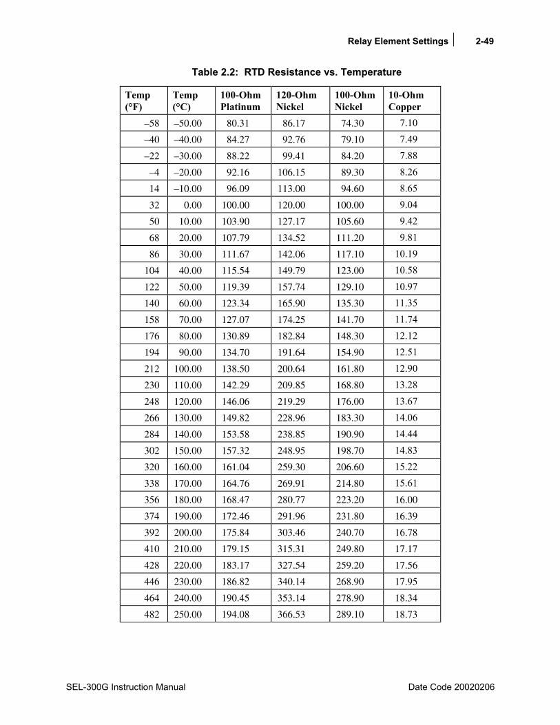
Relay Element Settings 2-49
SEL-300G Instruction Manual Date Code 20020206
Table 2.2: RTD Resistance vs. Temperature
Temp (°F)
Temp (°C)
100-Ohm Platinum
120-Ohm Nickel
100-OhmNickel
10-Ohm Copper
–58 –50.00 80.31 86.17 74.30 7.10
–40 –40.00 84.27 92.76 79.10 7.49
–22 –30.00 88.22 99.41 84.20 7.88
–4 –20.00 92.16 106.15 89.30 8.26
14 –10.00 96.09 113.00 94.60 8.65
32 0.00 100.00 120.00 100.00 9.04
50 10.00 103.90 127.17 105.60 9.42
68 20.00 107.79 134.52 111.20 9.81
86 30.00 111.67 142.06 117.10 10.19
104 40.00 115.54 149.79 123.00 10.58
122 50.00 119.39 157.74 129.10 10.97
140 60.00 123.34 165.90 135.30 11.35
158 70.00 127.07 174.25 141.70 11.74
176 80.00 130.89 182.84 148.30 12.12
194 90.00 134.70 191.64 154.90 12.51
212 100.00 138.50 200.64 161.80 12.90
230 110.00 142.29 209.85 168.80 13.28
248 120.00 146.06 219.29 176.00 13.67
266 130.00 149.82 228.96 183.30 14.06
284 140.00 153.58 238.85 190.90 14.44
302 150.00 157.32 248.95 198.70 14.83
320 160.00 161.04 259.30 206.60 15.22
338 170.00 164.76 269.91 214.80 15.61
356 180.00 168.47 280.77 223.20 16.00
374 190.00 172.46 291.96 231.80 16.39
392 200.00 175.84 303.46 240.70 16.78
410 210.00 179.15 315.31 249.80 17.17
428 220.00 183.17 327.54 259.20 17.56
446 230.00 186.82 340.14 268.90 17.95
464 240.00 190.45 353.14 278.90 18.34
482 250.00 194.08 366.53 289.10 18.73

2-50 Relay Element Settings
Date Code 20020206 SEL-300G Instruction Manual
Relay Word Bits
Relay Word Bit Function Description Typical Application
WDGTRIP Winding Temperature Trip (RTD voting and/or biasing applies if set)
Tripping, Indication, SER Triggering
WDGALRM Winding Temperature Alarm Indication, SER Triggering BRGTRIP Bearing Temperature Trip (RTD
voting applies if set) Tripping, Indication, SER Triggering
BRGALRM Bearing Temperature Alarm Indication, SER Triggering AMBTRIP Ambient Temperature Trip Tripping, Indication, SER
Triggering AMBALRM Ambient Temperature Alarm Indication, SER Triggering OTHTRIP Other Temperature Trip Tripping, Indication, SER
Triggering OTHALRM Other Temperature Alarm Indication, SER Triggering RTDFLT RTD Fault, open/shorted RTD or no
communication with the SEL-2600 Indication, SER Triggering
2600IN Contact Input from the SEL-2600 General purpose control/indication
Note: The above Relay Word bits are not programmed for any action in the factory default settings. They must be added to appropriate SELOGIC Control Equations and SER settings for Tripping, Alarm, SER triggering, etc.
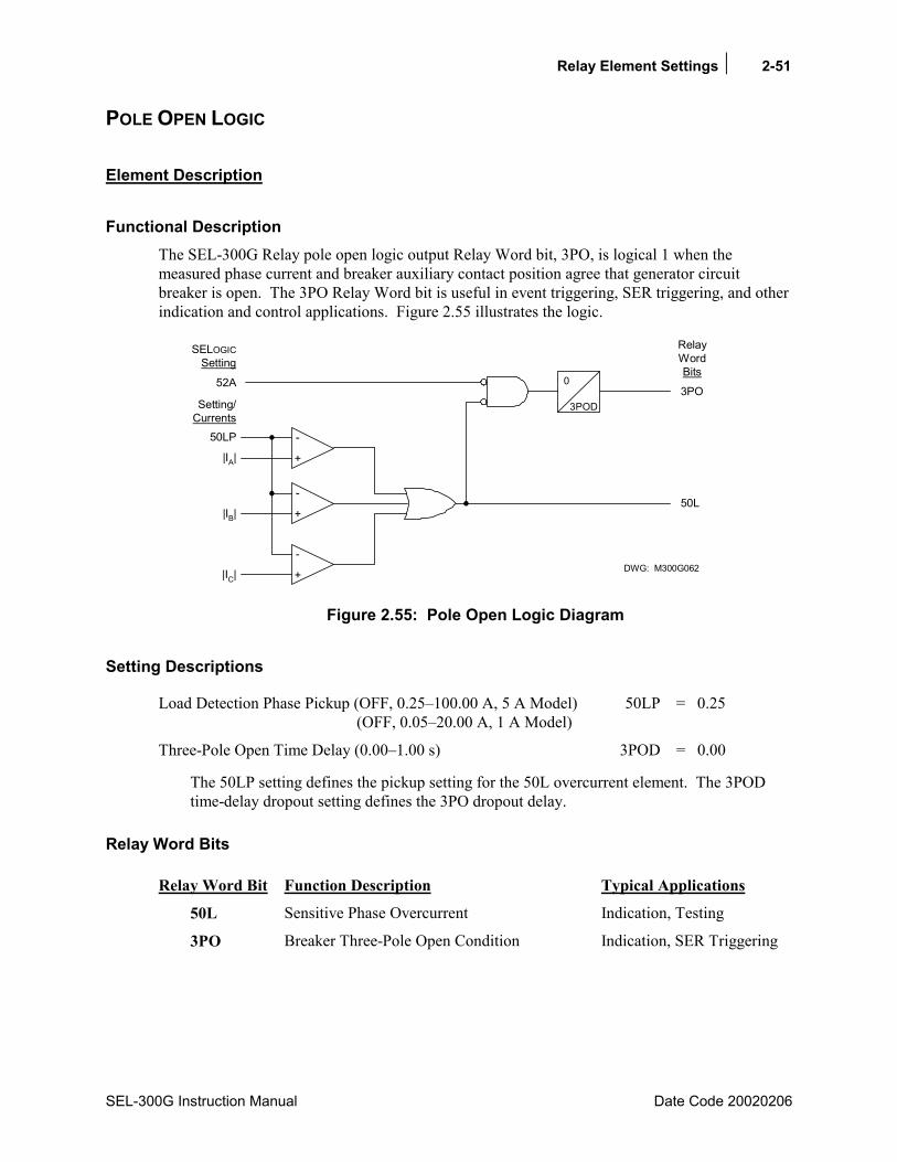
Relay Element Settings 2-51
SEL-300G Instruction Manual Date Code 20020206
POLE OPEN LOGIC
Element Description
Functional Description The SEL-300G Relay pole open logic output Relay Word bit, 3PO, is logical 1 when the measured phase current and breaker auxiliary contact position agree that generator circuit breaker is open. The 3PO Relay Word bit is useful in event triggering, SER triggering, and other indication and control applications. Figure 2.55 illustrates the logic.
3POD
0
RelayWordBits
SELOGICSetting
3PO52A
Setting/Currents
50LP
|IA|
|IB|
|IC|
+
-
50L
+
-
+
-
DWG: M300G062
Figure 2.55: Pole Open Logic Diagram
Setting Descriptions
Load Detection Phase Pickup (OFF, 0.25100.00 A, 5 A Model) 50LP = 0.25 (OFF, 0.0520.00 A, 1 A Model)
Three-Pole Open Time Delay (0.001.00 s) 3POD = 0.00
The 50LP setting defines the pickup setting for the 50L overcurrent element. The 3POD time-delay dropout setting defines the 3PO dropout delay.
Relay Word Bits
Relay Word Bit Function Description Typical Applications
50L Sensitive Phase Overcurrent Indication, Testing
3PO Breaker Three-Pole Open Condition Indication, SER Triggering
2-52 Relay Element Settings
Date Code 20020206 SEL-300G Instruction Manual
Pole Open Logic Setting Calculation
Recommendations Set 50LP to its minimum value. When the generator current is extremely low, the relay will rely on the 52A input status to indicate breaker position. Set 3POD = 0 cycles unless your application requires a specific time-delayed dropout.
INADVERTENT ENERGIZATION PROTECTION The SEL-300G Relay Inadvertent Energization protection function is provided by the INAD SELOGIC Control Equation. Refer to Section 4: SELOGIC® Control Equations for complete details and a setting example.
BREAKER FAILURE PROTECTION In some protection topologies, the SEL-300G Relay SELOGIC Control Equations and nondedicated overcurrent elements can provide breaker failure protection. Refer to Section 4: SELOGIC® Control Equations for complete details and a setting example.
DIFFERENTIAL PROTECTION Settings for the ground differential (87N) elements provided by relay Models 0300G0 and 0300G2 and the percentage restrained differential (87) elements provided by relay models 0300G1 and 0300G3 are described in Section 13: Differential Element Settings.
SYNCHRONISM CHECKING Settings for the optional synchronism checking function provided by relay models 0300G2 and 0300G3 are described in Section 4: SELOGIC® Control Equations.

SEL-300G Instruction Manual Date Code 20020206
TABLE OF CONTENTS
SECTION 3: AUXILIARY FUNCTION SETTINGS ..................................3-1
Introduction ...................................................................................................................................3-1 Demand Meter...............................................................................................................................3-1
Functional Description ..........................................................................................................3-1 Comparison of Thermal and Rolling Demand Meters ..................................................3-1
Demand Ammeter Thresholds...............................................................................................3-5 Setting Descriptions ..............................................................................................................3-5 Relay Word Bits ....................................................................................................................3-6
Station DC Monitor.......................................................................................................................3-8 Element Description..............................................................................................................3-8
Functional Description ..................................................................................................3-8 Setting Descriptions ......................................................................................................3-8 Relay Word Bits ............................................................................................................3-9
Create Desired Logic for DC Under- and Overvoltage Alarming ........................................3-9 DCLO < DCHI (Top of Figure 3.5) ............................................................................3-10 DCLO > DCHI (Bottom of Figure 3.5) .......................................................................3-11 Output Contact Type Considerations (a or b) ......................................................3-11
Setting Group Selection Function ...............................................................................................3-12 Active Setting Group Indication .........................................................................................3-12 Selecting the Active Setting Group.....................................................................................3-12 Operation of SELOGIC® Control Equation Settings SS1 and SS2 ......................................3-12 Operation of Serial Port GROUP Command and Front-Panel GROUP Pushbutton ..........3-13 Relay Disabled Momentarily During Active Setting Group Change..................................3-13 Active Setting Group Switching Example ..........................................................................3-13
Feedback Control.........................................................................................................3-15 Rising Edge Operators.................................................................................................3-15
Active Setting Group Retained ...........................................................................................3-18 Power Loss ..................................................................................................................3-18 Settings Change ...........................................................................................................3-18
Breaker Monitor Function...........................................................................................................3-19 Breaker Monitor Setting Example.......................................................................................3-21
Breaker Maintenance Curve Details............................................................................3-21 Operation of SELOGIC Control Equation Breaker Monitor Initiation Setting
BKMON ..............................................................................................................3-23 Optoisolated Input Debounce Timers .........................................................................................3-24
Input Debounce Timers .......................................................................................................3-25 Input Functions....................................................................................................................3-26 Factory Settings Example....................................................................................................3-26
Input IN101..................................................................................................................3-26 SER Trigger Settings and Alias Settings ....................................................................................3-27
SER Triggering....................................................................................................................3-27 Making SER Trigger Settings .............................................................................................3-27 Alias Settings.......................................................................................................................3-28

ii Auxiliary Function Settings
Date Code 20020206 SEL-300G Instruction Manual
TABLES Table 3.1: Definitions for Active Setting Group Indication Relay Word Bits SG1 and SG2 .............3-12 Table 3.2: Definitions for Active Setting Group Switching SELOGIC Control Equation Settings
SS1 And SS2 ................................................................................................................3-12 Table 3.3: Breaker Maintenance Information for a 13.8 kV Circuit Breaker ......................................3-19 Table 3.4: Breaker Monitor Settings and Settings Ranges ..................................................................3-21
FIGURES Figure 3.1: Response of Thermal and Rolling Demand Meters to a Step Input (setting
DMTC = 15 minutes) .....................................................................................................3-2 Figure 3.2: Voltage VS Applied to Series RC Circuit .............................................................................3-3 Figure 3.3: Demand Current Logic Outputs............................................................................................3-7 Figure 3.4: DC Under- and Overvoltage Elements .................................................................................3-8 Figure 3.5: Create DC Voltage Elements with SELOGIC Control Equations........................................3-10 Figure 3.6: SCADA Contact Pulses Input IN104 to Switch Active Relay Setting Groups ..................3-14 Figure 3.7: Latch Control Switch Controlled by a Single Input to Switch Active Setting Group ........3-14 Figure 3.8: Latch Control Switch Operation Time Line .......................................................................3-17 Figure 3.9: Plotted Breaker Maintenance Points for a 13.8 kV Circuit Breaker...................................3-20 Figure 3.10: SEL-300G Relay Breaker Maintenance Curve for a 13.8 kV Circuit Breaker...................3-23 Figure 3.11: Operation of SELOGIC Control Equation Breaker Monitor Initiation Setting....................3-23 Figure 3.12: Example Operation of Optoisolated Inputs IN101 Through IN106 (All Models)..............3-24 Figure 3.13: Example Operation of Optoisolated Inputs IN201 Through IN208 - Extra I/O Board
(Models 0300G_1 and 0300G_Y) ................................................................................3-25 Figure 3.14: Circuit Breaker Auxiliary Contacts Connected to Optoisolated Inputs IN101and
IN102 ............................................................................................................................3-26 Figure 3.15: Example Sequential Events Recorder (SER) Event Report................................................3-28

Auxiliary Function Settings 3-1
SEL-300G Instruction Manual Date Code 20020206
SECTION 3: AUXILIARY FUNCTION SETTINGS
INTRODUCTION This section describes the following functions and their settings.
• Demand Meter
• Station DC Monitor
• Setting Group Selection Function
• Breaker Monitor Function
• Optoisolated Input Debounce Timers
• SER Trigger Settings and Alias Settings
DEMAND METER
Functional Description The SEL-300G Relay offers the choice between two types of demand metering, settable with the enable setting:
EDEM = THM (Thermal Demand Meter) or EDEM = ROL (Rolling Demand Meter)
The relay provides demand and peak demand metering for the following values:
Currents IA,B,C,N Input currents (A primary) IG Residual ground current (A primary; IG =3I0 = IA + IB + IC) 3I2 Negative-sequence current (A primary)
Power MWA,B,C,3P Single- (when Delta_Y = 4) and three-phase megawatts MVARA,B,C,3P Single- (when Delta_Y = 4) and three-phase megavars
Depending on enable setting EDEM, these demand and peak demand values are thermal demand or rolling demand values. The differences between thermal and rolling demand metering are explained in the following discussion.
Comparison of Thermal and Rolling Demand Meters The example in Figure 3.1 shows the response of thermal and rolling demand meters to a step current input. The current input is at a magnitude of zero and then suddenly goes to a magnitude of 1.0 per unit.
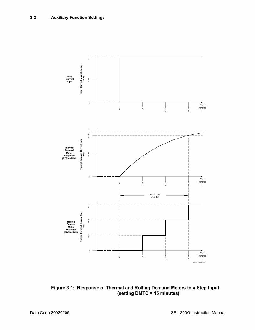
3-2 Auxiliary Function Settings
Date Code 20020206 SEL-300G Instruction Manual
DWG: M300G124
Time(minutes)
Rol
ling
Dem
and
Cur
rent
(per
unit)
1.0
0
0 5 10
15
Ther
mal
Dem
and
Cur
rent
(per
unit)
0
0.5
1.0
0 5 10
(minutes)
Time1
5
Inpu
t Cur
rent
Mag
nitu
de (p
erun
it)
0
0.5
1.0
0 5 10
(minutes)
Time1
5
0.9
DMTC=15minutes
.67
.33
RollingDemand
MeterResponse
(EDEM=ROL)
ThermalDemand
MeterResponse
(EDEM=THM)
StepCurrent
Input
Figure 3.1: Response of Thermal and Rolling Demand Meters to a Step Input (setting DMTC = 15 minutes)
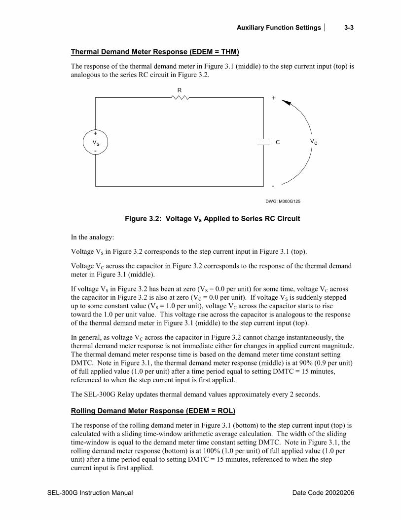
Auxiliary Function Settings 3-3
SEL-300G Instruction Manual Date Code 20020206
Thermal Demand Meter Response (EDEM = THM)
The response of the thermal demand meter in Figure 3.1 (middle) to the step current input (top) is analogous to the series RC circuit in Figure 3.2.
DWG: M300G125
+
-
VcC
R
Vs
+
-
Figure 3.2: Voltage VS Applied to Series RC Circuit
In the analogy:
Voltage VS in Figure 3.2 corresponds to the step current input in Figure 3.1 (top).
Voltage VC across the capacitor in Figure 3.2 corresponds to the response of the thermal demand meter in Figure 3.1 (middle).
If voltage VS in Figure 3.2 has been at zero (VS = 0.0 per unit) for some time, voltage VC across the capacitor in Figure 3.2 is also at zero (VC = 0.0 per unit). If voltage VS is suddenly stepped up to some constant value (VS = 1.0 per unit), voltage VC across the capacitor starts to rise toward the 1.0 per unit value. This voltage rise across the capacitor is analogous to the response of the thermal demand meter in Figure 3.1 (middle) to the step current input (top).
In general, as voltage VC across the capacitor in Figure 3.2 cannot change instantaneously, the thermal demand meter response is not immediate either for changes in applied current magnitude. The thermal demand meter response time is based on the demand meter time constant setting DMTC. Note in Figure 3.1, the thermal demand meter response (middle) is at 90% (0.9 per unit) of full applied value (1.0 per unit) after a time period equal to setting DMTC = 15 minutes, referenced to when the step current input is first applied.
The SEL-300G Relay updates thermal demand values approximately every 2 seconds.
Rolling Demand Meter Response (EDEM = ROL)
The response of the rolling demand meter in Figure 3.1 (bottom) to the step current input (top) is calculated with a sliding time-window arithmetic average calculation. The width of the sliding time-window is equal to the demand meter time constant setting DMTC. Note in Figure 3.1, the rolling demand meter response (bottom) is at 100% (1.0 per unit) of full applied value (1.0 per unit) after a time period equal to setting DMTC = 15 minutes, referenced to when the step current input is first applied.

3-4 Auxiliary Function Settings
Date Code 20020206 SEL-300G Instruction Manual
When EDM = ROL, the rolling demand meter integrates the applied signal input in 5-minute intervals. The integration is performed approximately every 2 seconds. The average value for an integrated 5-minute interval is stored as a 5-minute total. The rolling demand meter then averages a number of the 5-minute totals to produce the rolling demand meter response. In the Figure 3.1 example, the rolling demand meter averages the three latest 5-minute totals because setting DMTC = 15 (15/5 = 3). The rolling demand meter response is updated every 5 minutes, after a new 5-minute total is calculated.
The following is a step-by-step calculation of the rolling demand response example in Figure 3.1 (bottom).
Time = 0 Minutes
Presume that the input current magnitude has been at zero for quite some time before Time = 0 minutes (or the demand meters were reset). The three 5-minute intervals in the sliding time-window at Time = 0 minutes each integrate into the following 5-minute totals:
5-Minute Totals
Corresponding 5-Minute Interval
0.0 per unit -15 to -10 minutes
0.0 per unit -10 to -5 minutes
0.0 per unit -5 to 0 minutes
0.0 per unit
Rolling demand meter response at Time = 0 minutes = 0.0/3 = 0.0 per unit
Time = 5 Minutes
The three 5-minute intervals in the sliding time-window at Time = 5 minutes each integrate into the following 5-minute totals:
5-Minute Totals
Corresponding 5-Minute Interval
0.0 per unit -10 to -5 minutes
0.0 per unit -5 to 0 minutes
1.0 per unit 0 to 5 minutes
1.0 per unit
Rolling demand meter response at Time = 5 minutes = 1.0/3 = 0.33 per unit
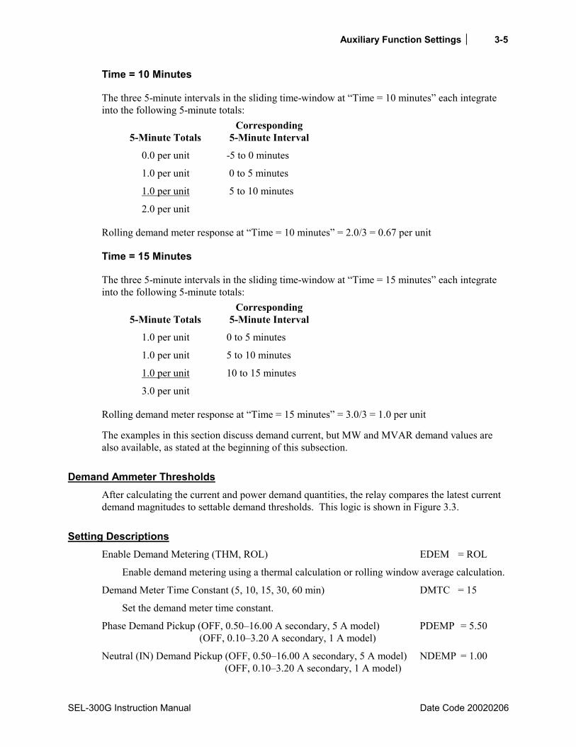
Auxiliary Function Settings 3-5
SEL-300G Instruction Manual Date Code 20020206
Time = 10 Minutes
The three 5-minute intervals in the sliding time-window at Time = 10 minutes each integrate into the following 5-minute totals:
5-Minute Totals
Corresponding 5-Minute Interval
0.0 per unit -5 to 0 minutes
1.0 per unit 0 to 5 minutes
1.0 per unit 5 to 10 minutes
2.0 per unit
Rolling demand meter response at Time = 10 minutes = 2.0/3 = 0.67 per unit
Time = 15 Minutes
The three 5-minute intervals in the sliding time-window at Time = 15 minutes each integrate into the following 5-minute totals:
5-Minute Totals
Corresponding 5-Minute Interval
1.0 per unit 0 to 5 minutes
1.0 per unit 5 to 10 minutes
1.0 per unit 10 to 15 minutes
3.0 per unit
Rolling demand meter response at Time = 15 minutes = 3.0/3 = 1.0 per unit
The examples in this section discuss demand current, but MW and MVAR demand values are also available, as stated at the beginning of this subsection.
Demand Ammeter Thresholds After calculating the current and power demand quantities, the relay compares the latest current demand magnitudes to settable demand thresholds. This logic is shown in Figure 3.3.
Setting Descriptions Enable Demand Metering (THM, ROL) EDEM = ROL
Enable demand metering using a thermal calculation or rolling window average calculation.
Demand Meter Time Constant (5, 10, 15, 30, 60 min) DMTC = 15
Set the demand meter time constant.
Phase Demand Pickup (OFF, 0.5016.00 A secondary, 5 A model) PDEMP = 5.50 (OFF, 0.103.20 A secondary, 1 A model)
Neutral (IN) Demand Pickup (OFF, 0.5016.00 A secondary, 5 A model) NDEMP = 1.00 (OFF, 0.103.20 A secondary, 1 A model)

3-6 Auxiliary Function Settings
Date Code 20020206 SEL-300G Instruction Manual
Residual (3I0) Demand Pickup (OFF, 0.5 - 16 A secondary, 5 A model) GDEMP = 1.00 (OFF = 0.10 - 3.20 A secondary, 1 A model)
Neg.-Seq. Demand Pickup (OFF, 0.5 - 16 A secondary, 5 A model) QDEMP = 1.00 (OFF = 0.10 - 3.20 A secondary, 1 A model)
Note: When you change either setting EDEM or DMTC, the relay resets the demand meter values to zero. If you change the active setting group and the new group is set with a different EDEM or DMTC setting, the relay also resets the demand meter values to zero. Demand current pickup settings PDEMP, NDEMP, GDEMP, and QDEMP can be changed without affecting the demand meters.
The demand current pickup settings are applied to demand current meter outputs as shown in Figure 3.3. For example, when residual ground demand current IG(DEM) goes above corresponding demand pickup GDEMP, Relay Word bit GDEM asserts to logical 1. Use these demand current logic outputs (PDEM, NDEM, GDEM, and QDEM) to alarm for high loading or unbalance conditions.
Relay Word Bits Relay Word Bit Function Description Typical Applications
PDEM Phase Demand Current Exceeds Pickup Indication, Testing
NDEM Neutral Demand Current Exceeds Pickup Indication, Testing
GDEM Residual Demand Current Exceeds Pickup Indication, Testing
QDEM Neg.-Seq. Demand Current Exceeds Pickup Indication, Testing
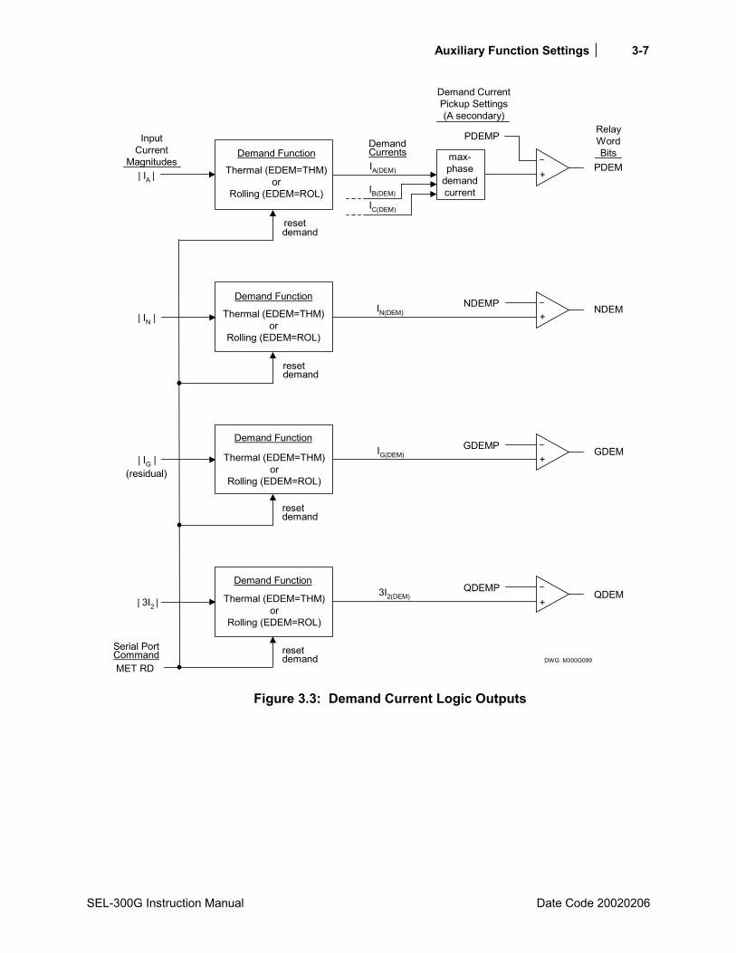
Auxiliary Function Settings 3-7
SEL-300G Instruction Manual Date Code 20020206
DWG: M300G099
| 3I2 |
| IG |
| IN |
resetdemand
demandreset
demandreset
demandreset
(residual)
IA(DEM)
IB(DEM)
IC(DEM)
+
PDEMPDemandCurrents
PDEM
RelayWordBits
IN(DEM) NDEM+
NDEMP
IG(DEM) GDEMGDEMP+
3I2(DEM) QDEMQDEMP
+
MET RD
Serial PortCommand
Demand FunctionInput
CurrentMagnitudes
Demand CurrentPickup Settings(A secondary)
Thermal (EDEM=THM)or
Rolling (EDEM=ROL)
Demand Function
Thermal (EDEM=THM)or
Rolling (EDEM=ROL)
Demand Function
Thermal (EDEM=THM)or
Rolling (EDEM=ROL)
Demand Function
Thermal (EDEM=THM)or
Rolling (EDEM=ROL)
| IA |
max-phase
demandcurrent
Figure 3.3: Demand Current Logic Outputs

3-8 Auxiliary Function Settings
Date Code 20020206 SEL-300G Instruction Manual
STATION DC MONITOR
Element Description
Functional Description The SEL-300G Relay directly measures the dc voltage applied to the + and - power supply input terminals, Z25 and Z26. The relay reports the measured dc voltage in the meter function and in the event report data. The relay also compares the measured voltage magnitude to two settable thresholds which generate Relay Word bits for control and indication.
If the SEL-300G Relay has a 125/250 Vac/Vdc supply, it can be powered by ac voltage (85 to 264 Vac) connected to the rear-panel terminals labeled POWER. When powering the relay with ac voltage, the dc voltage elements in Figure 3.4 sees the average of the sampled ac voltage powering the relay which is very near zero volts (as displayed in column Vdc in event reports). Thus, pickup settings DCLOP and DCHIP should be set off (DCLOP = OFF, DCHIP = OFF) they are of no real use.
If an event report is displayed with the EVE R command, column Vdc will display the sampled ac voltage waveform, rather than the average.
Setting Descriptions DC Battery Voltage Level 1 (OFF, 20 - 300 Vdc) DCHIP = OFF
DC Battery Voltage Level 2 (OFF, 20 - 300 Vdc) DCLOP = OFF
The DCHIP and DCLOP setting ranges allow the SEL-300G Relay to monitor nominal battery voltages of 24, 48, 125, and 250 V. When testing the pickup settings DCLOP and DCHIP, do not operate the relay outside of its power supply limits. The relay is shipped with either a 24/48 V supply with operating range of 20 to 60 Vdc or a 125/250 V supply with operating range of 85 to 350 Vdc. The power supply rating is located on the serial number sticker on the relay rear panel.
DWG: M300G126
-+
-+
DCLOP
DCHIP
Settings
Vdc
DCLO
DCHI
under-voltage
voltageover-
(from rearpanel terminals
labeled POWER)
RelayWordBits
Figure 3.4: DC Under- and Overvoltage Elements
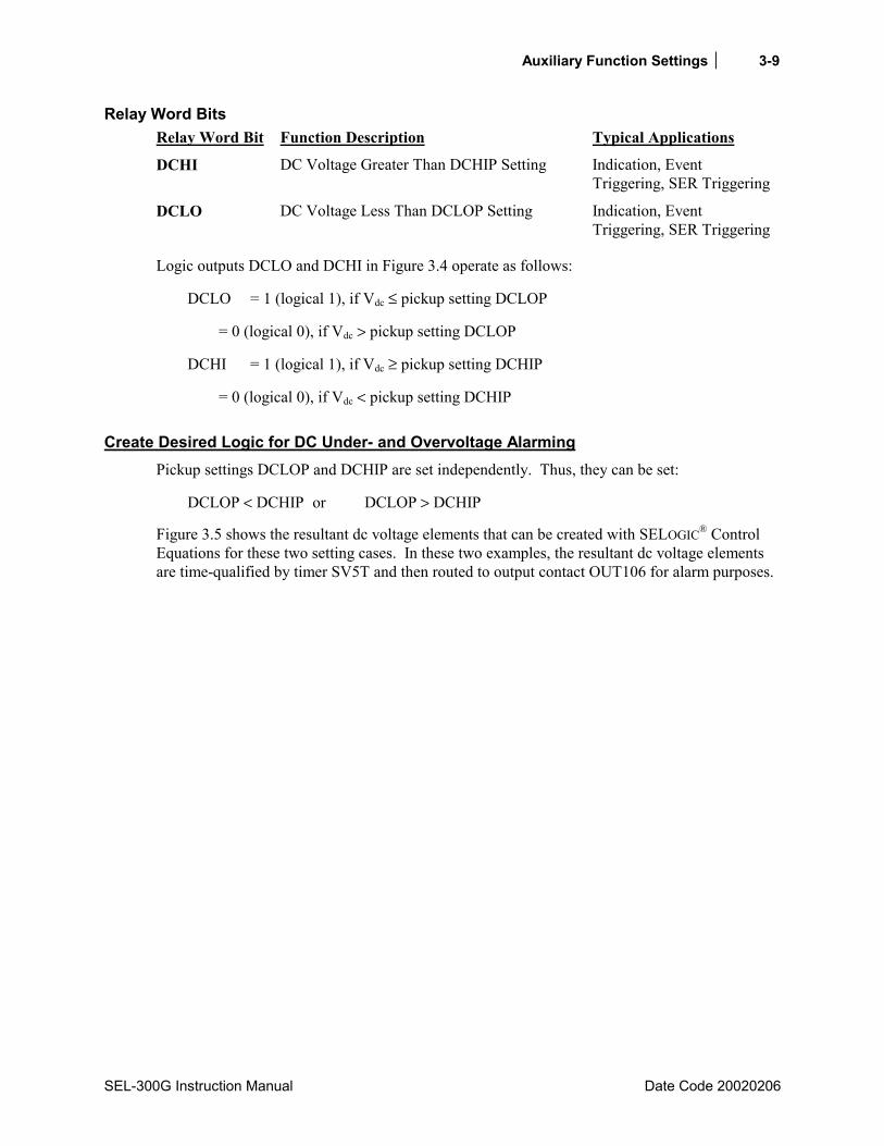
Auxiliary Function Settings 3-9
SEL-300G Instruction Manual Date Code 20020206
Relay Word Bits Relay Word Bit Function Description Typical Applications
DCHI DC Voltage Greater Than DCHIP Setting Indication, Event Triggering, SER Triggering
DCLO DC Voltage Less Than DCLOP Setting Indication, Event Triggering, SER Triggering
Logic outputs DCLO and DCHI in Figure 3.4 operate as follows:
DCLO = 1 (logical 1), if Vdc ≤ pickup setting DCLOP
= 0 (logical 0), if Vdc > pickup setting DCLOP
DCHI = 1 (logical 1), if Vdc ≥ pickup setting DCHIP
= 0 (logical 0), if Vdc < pickup setting DCHIP
Create Desired Logic for DC Under- and Overvoltage Alarming Pickup settings DCLOP and DCHIP are set independently. Thus, they can be set:
DCLOP < DCHIP or DCLOP > DCHIP
Figure 3.5 shows the resultant dc voltage elements that can be created with SELOGIC® Control Equations for these two setting cases. In these two examples, the resultant dc voltage elements are time-qualified by timer SV5T and then routed to output contact OUT106 for alarm purposes.
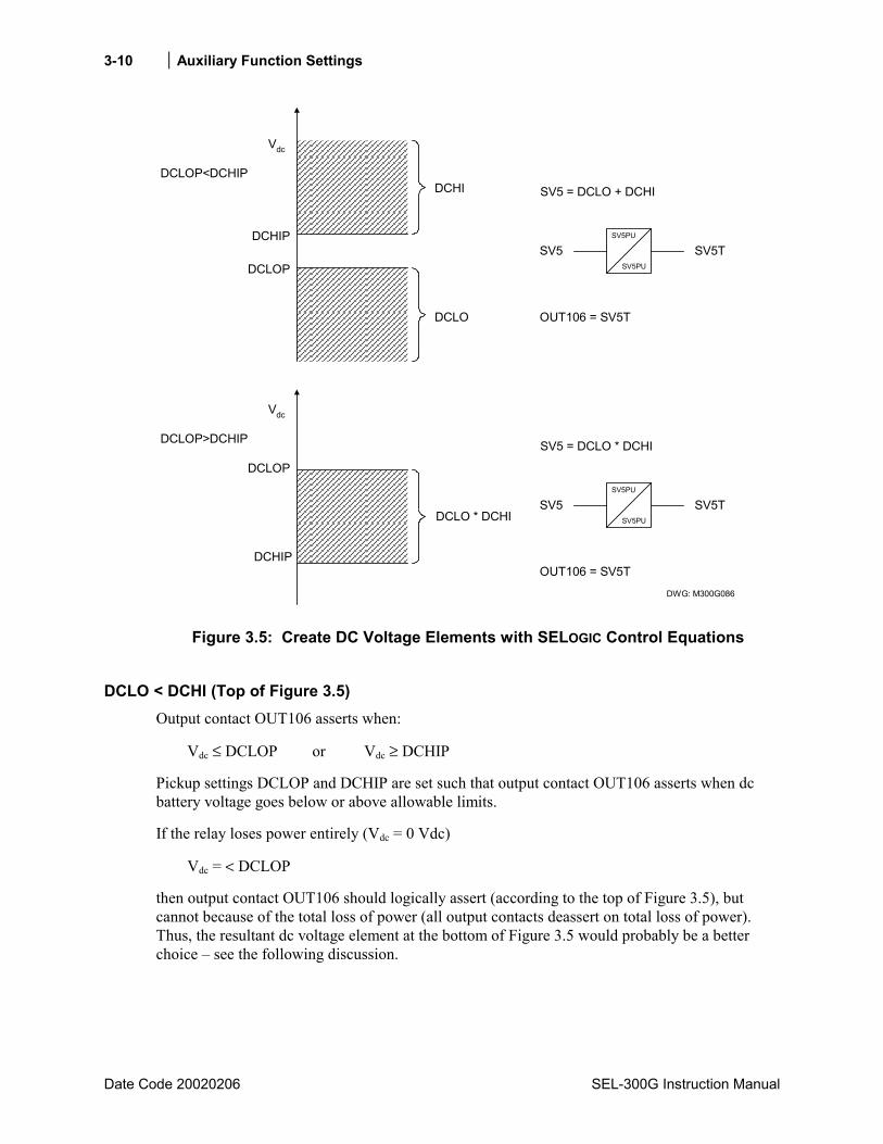
3-10 Auxiliary Function Settings
Date Code 20020206 SEL-300G Instruction Manual
DCLO
Vdc
DCHIP
DCLOP<DCHIPSV5 = DCLO + DCHI
OUT106 = SV5T
DWG: M300G086
SV5T
DCLO * DCHI
SV5PU
DCLOP
DCHI
SV5SV5PU
SV5 = DCLO * DCHI
OUT106 = SV5T
SV5TSV5PU
SV5SV5PU
DCLOP
Vdc
DCLOP>DCHIP
DCHIP
Figure 3.5: Create DC Voltage Elements with SELOGIC Control Equations
DCLO < DCHI (Top of Figure 3.5) Output contact OUT106 asserts when:
Vdc ≤ DCLOP or Vdc ≥ DCHIP
Pickup settings DCLOP and DCHIP are set such that output contact OUT106 asserts when dc battery voltage goes below or above allowable limits.
If the relay loses power entirely (Vdc = 0 Vdc)
Vdc = < DCLOP
then output contact OUT106 should logically assert (according to the top of Figure 3.5), but cannot because of the total loss of power (all output contacts deassert on total loss of power). Thus, the resultant dc voltage element at the bottom of Figure 3.5 would probably be a better choice see the following discussion.

Auxiliary Function Settings 3-11
SEL-300G Instruction Manual Date Code 20020206
DCLO > DCHI (Bottom of Figure 3.5) Output contact OUT106 asserts when:
DCHIP ≤ Vdc ≤ DCLOP
Pickup settings DCLOP and DCHIP are set such that output contact OUT106 asserts when dc battery voltage stays between allowable limits.
If the relay loses power entirely (Vdc = 0 Vdc)
Vdc = < DCHIP
then output contact OUT106 should logically deassert (according to the bottom of Figure 3.5), and this is surely what happens for a total loss of power (all output contacts deassert on total loss of power).
Output Contact Type Considerations (a or b) Consider the output contact type (a or b) needed for output contact OUT106 in the bottom of Figure 3.5 (dc voltage alarm example).
If SELOGIC Control Equation setting OUT106 is asserted (OUT106 = SV5T = logical 1; dc voltage OK), the state of output contact OUT106 (according to contact type) is:
closed (a type output contact)
open (b type output contact)
If SELOGIC Control Equation setting OUT106 is deasserted (OUT106 = SV5T = logical 0; dc voltage not OK), the state of output contact OUT106 (according to contact type) is:
open (a type output contact)
closed (b type output contact)
If the relay loses power entirely, all output contacts deassert, and the state of output contact OUT106 (according to contact type) is:
open (a type output contact)
closed (b type output contact)
Note that in this case, the relay ALARM output contact (b type output contact) also closed (see Figure 4.16).

3-12 Auxiliary Function Settings
Date Code 20020206 SEL-300G Instruction Manual
SETTING GROUP SELECTION FUNCTION The relay has two (2) independent setting groups. Each setting group has complete relay and SELOGIC Control Equation settings.
Active Setting Group Indication Only one setting group can be active at a time. Relay Word bits SG1 and SG2 indicate the active setting group.
Table 3.1: Definitions for Active Setting Group Indication Relay Word Bits SG1 and SG2
Relay Word Bit Definition
SG1 Indication that setting Group 1 is the active setting group
SG2 Indication that setting Group 2 is the active setting group
For example, if setting Group 2 is the active setting group, Relay Word bit SG2 asserts to logical 1, and SG1 deasserts to logical 0.
Selecting the Active Setting Group The active setting group is selected with
SELOGIC Control Equation settings SS1 and SS2.
The serial port GROUP command (see Section 10: Serial Port Communications and Commands).
Or the front-panel GROUP pushbutton (see Section 9: Front-Panel Operation).
SELOGIC Control Equation settings SS1 and SS2 have priority over the serial port GROUP command and the front-panel GROUP pushbutton in selecting the active setting group.
Operation of SELOGIC Control Equation Settings SS1 and SS2 SELOGIC Control Equation settings SS1 and SS2 appear in the relay Global Settings.
Table 3.2: Definitions for Active Setting Group Switching SELOGIC Control Equation Settings SS1 And SS2
Setting Definition
SS1 go to (or remain in) setting Group 1
SS2 go to (or remain in) setting Group 2
The operation of these settings is explained with the following example.

Auxiliary Function Settings 3-13
SEL-300G Instruction Manual Date Code 20020206
Assume the active setting group starts out as setting Group 1. Corresponding Relay Word bit SG1 is asserted to logical 1 as an indication that setting Group 1 is the active setting group (see Table 3.1).
With setting Group 1 as the active setting group, setting SS1 has priority. If setting SS1 is asserted to logical 1, setting Group 1 remains the active setting group, regardless of the activity of setting SS2. With settings SS1 and SS2 deasserted to logical 0, setting Group 1 still remains the active setting group.
With setting Group 1 as the active setting group, if setting SS1 is deasserted to logical 0 and SS2 asserts to logical 1, the relay switches from setting Group 1 as the active setting group to Group 2 as the active setting group, after qualifying time setting TGR. In this example, TGR qualifies the assertion of setting SS2 before it can change the active setting group.
Having switched to Group 2, as long as SS2 remains asserted, the relay will remain in Group 2 regardless of the activity of setting SS1.
Operation of Serial Port GROUP Command and Front-Panel GROUP Pushbutton SELOGIC Control Equation settings SS1 and SS2 have priority over the serial port GROUP command and the front-panel GROUP pushbutton in selecting the active setting group. If either one of SS1 or SS2 asserts to logical 1, neither the serial port GROUP command nor the front-panel GROUP pushbutton can be used to switch the active setting group. But if SS1 and SS2 both deassert to logical 0, the serial port GROUP command or the front-panel GROUP pushbutton can be used to switch the active setting group.
See Section 10: Serial Port Communications and Commands for more information on the serial port GROUP command. See Section 9: Front-Panel Operation for more information on the front-panel GROUP pushbutton.
Relay Disabled Momentarily During Active Setting Group Change The relay is disabled for a few seconds while the relay is in the process of changing active setting groups. Relay elements, timers, and logic are reset, unless indicated otherwise in specific logic description. Local bits LB1 through LB16 and latch bits LT1 through LT16 states are retained during an active setting group change.
Active Setting Group Switching Example Use a latch control switch to select setting Group 1 and 2 in the SEL-300G Relay. In this example, a SCADA contact is connected to optoisolated input IN104. Each pulse of the SCADA contact changes the active relay setting group. The SCADA contact is not maintained, just pulsed to switch setting groups.

3-14 Auxiliary Function Settings
Date Code 20020206 SEL-300G Instruction Manual
DWG: M300G083(-)
SCADA Switch Active Setting Group
(+)
IN104
SEL-300G
Figure 3.6: SCADA Contact Pulses Input IN104 to Switch Active Relay Setting Groups
If setting Group 1 is active and the SCADA contact is pulsed, the setting Group 2 is then activated. If the SCADA contact is pulsed again, the setting Group 1 is reactivated.
This logic is implemented in the following SELOGIC Control Equation settings and displayed in Figure 3.7. (Refer to Section 4: SELOGIC Control Equations for additional information on SELOGIC Control Equations and the latch control switch function.)
SET5 = /IN104*!LT5 [= (rising edge of input IN104) AND NOT(LT5)]
RST5 = /IN104*LT5 [= (rising edge of input IN104) AND LT5]
SS1 = LT5 [= LT5; activate setting Group 1]
SS2 = !LT5 [= NOT(LT5); activate setting Group 2]
DWG: M300G084
LT5
IN104
(set)
(reset)
rising edgedetect
SET5
RelayWord
Bit RST5
SELOGICSetting
SELOGICSetting
RelayWord
Bit
Figure 3.7: Latch Control Switch Controlled by a Single Input to Switch Active Setting Group
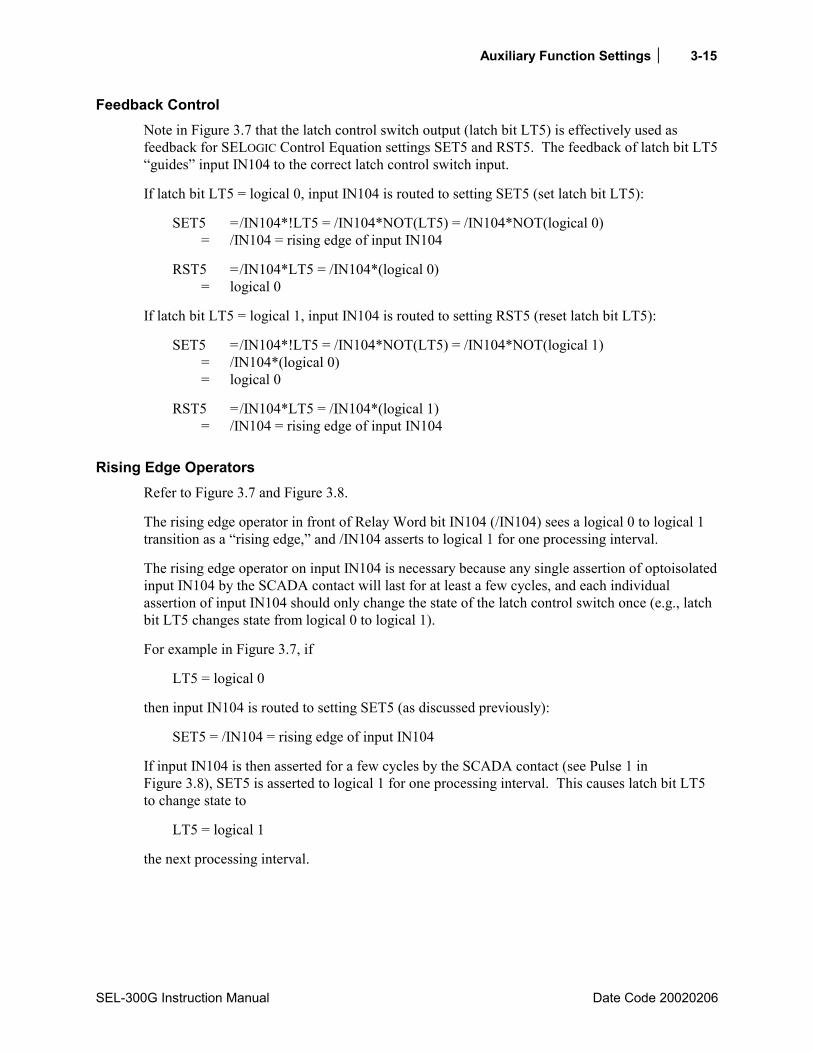
Auxiliary Function Settings 3-15
SEL-300G Instruction Manual Date Code 20020206
Feedback Control Note in Figure 3.7 that the latch control switch output (latch bit LT5) is effectively used as feedback for SELOGIC Control Equation settings SET5 and RST5. The feedback of latch bit LT5 guides input IN104 to the correct latch control switch input.
If latch bit LT5 = logical 0, input IN104 is routed to setting SET5 (set latch bit LT5):
SET5 = /IN104*!LT5 = /IN104*NOT(LT5) = /IN104*NOT(logical 0) = /IN104 = rising edge of input IN104
RST5 = /IN104*LT5 = /IN104*(logical 0) = logical 0
If latch bit LT5 = logical 1, input IN104 is routed to setting RST5 (reset latch bit LT5):
SET5 = /IN104*!LT5 = /IN104*NOT(LT5) = /IN104*NOT(logical 1) = /IN104*(logical 0) = logical 0
RST5 = /IN104*LT5 = /IN104*(logical 1) = /IN104 = rising edge of input IN104
Rising Edge Operators Refer to Figure 3.7 and Figure 3.8.
The rising edge operator in front of Relay Word bit IN104 (/IN104) sees a logical 0 to logical 1 transition as a rising edge, and /IN104 asserts to logical 1 for one processing interval.
The rising edge operator on input IN104 is necessary because any single assertion of optoisolated input IN104 by the SCADA contact will last for at least a few cycles, and each individual assertion of input IN104 should only change the state of the latch control switch once (e.g., latch bit LT5 changes state from logical 0 to logical 1).
For example in Figure 3.7, if
LT5 = logical 0
then input IN104 is routed to setting SET5 (as discussed previously):
SET5 = /IN104 = rising edge of input IN104
If input IN104 is then asserted for a few cycles by the SCADA contact (see Pulse 1 in Figure 3.8), SET5 is asserted to logical 1 for one processing interval. This causes latch bit LT5 to change state to
LT5 = logical 1
the next processing interval.

3-16 Auxiliary Function Settings
Date Code 20020206 SEL-300G Instruction Manual
With latch bit LT5 now at logical 1 for the next processing interval, input IN104 is routed to setting RST5 (as discussed previously):
RST5 = /IN104 = rising edge of input IN104
This would then appear to enable the reset input (setting RST5) the next processing interval. But the rising edge condition occurred in the preceding processing interval. /IN104 is now at logical 0, so setting RST5 does not assert, even though input IN104 remains asserted for more than a few cycles by the SCADA contact.
If the SCADA contact deasserts and then asserts again (new rising edge see Pulse 2 in Figure 3.8), the reset input (setting RST5) asserts and latch bit LT5 deasserts back to logical 0 again. Thus each individual assertion of input IN104 (Pulse 1, Pulse 2, Pulse 3, and Pulse 4 in Figure 3.8) changes the state of latch control switch just once.
Note: Refer to subsection Optoisolated Input Debounce Timers Figure 3.12. Relay Word bit IN104 shows the state of optoisolated input IN104 after the input pickup/dropout debounce timer IN104D. Thus, when using Relay Word bit IN104 in Figure 3.7 and associated SELOGIC Control Equations, keep in mind any time delay produced by the input pickup/dropout debounce timer IN104D.
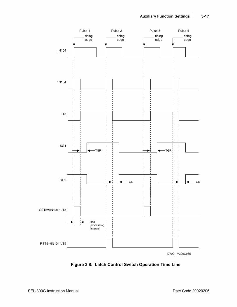
Auxiliary Function Settings 3-17
SEL-300G Instruction Manual Date Code 20020206
DWG: M300G085
oneprocessinginterval
RST5=/IN104*LT5
SET5=/IN104*!LT5
SG2
SG1
LT5
/IN104
IN104
TGR
risingedge
Pulse 1risingedge
Pulse 2risingedge
Pulse 3risingedge
Pulse 4
TGR
TGR TGR
Figure 3.8: Latch Control Switch Operation Time Line

3-18 Auxiliary Function Settings
Date Code 20020206 SEL-300G Instruction Manual
Active Setting Group Retained
Power Loss The active setting group is retained if power to the relay is lost and then restored. If a particular setting group is active when power is lost, the relay uses the same active setting group when power is restored.
Settings Change If individual settings are changed (for the active setting group or one of the other setting groups), the active setting group is retained, much like in the preceding Power Loss explanation.
If individual settings are changed for a setting group other than the active setting group, there is no interruption of the active setting group (the relay is not momentarily disabled).
If the individual settings change causes a change in one or more SELOGIC Control Equation settings SS1 or SS2, the active setting group can be changed, subject to the newly enabled SS1 and SS2 settings.
NOTE: Make Active Setting Group Switching Settings With Care
The active setting group is stored in nonvolatile memory so it can be retained during power loss or settings change. The nonvolatile memory is rated for a finite number of writes for all setting group changes. Exceeding the limit can result in an EEPROM self-test failure. An average of 10 setting groups changes per day can be made for a 25 year relay service life.
This requires that SELOGIC Control Equation settings SS1 and SS2 be set with care. Do not use SS1 or SS2 settings that result in continuous cyclical changing of the active setting group. Time setting TGR qualifies settings SS1 and SS2 before changing the active setting group. If optoisolated inputs are used in settings SS1 or SS2, the inputs have their own built-in debounce timer that can help in providing the necessary time qualification.
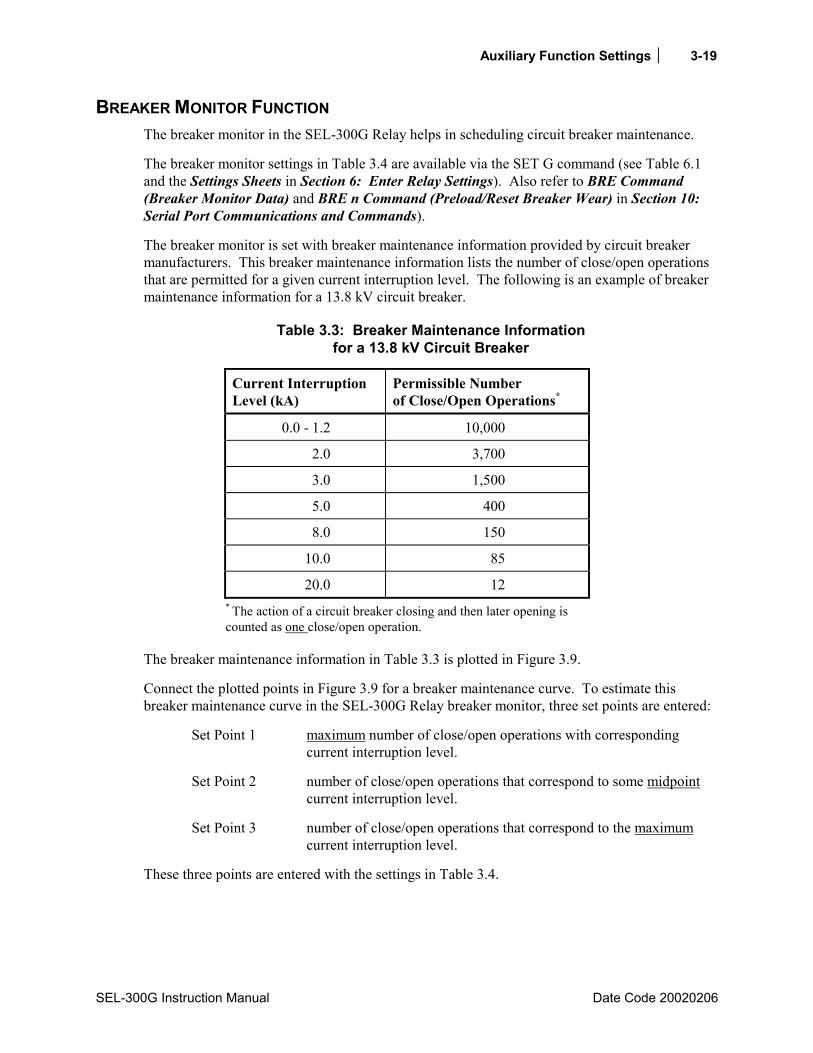
Auxiliary Function Settings 3-19
SEL-300G Instruction Manual Date Code 20020206
BREAKER MONITOR FUNCTION The breaker monitor in the SEL-300G Relay helps in scheduling circuit breaker maintenance.
The breaker monitor settings in Table 3.4 are available via the SET G command (see Table 6.1 and the Settings Sheets in Section 6: Enter Relay Settings). Also refer to BRE Command (Breaker Monitor Data) and BRE n Command (Preload/Reset Breaker Wear) in Section 10: Serial Port Communications and Commands).
The breaker monitor is set with breaker maintenance information provided by circuit breaker manufacturers. This breaker maintenance information lists the number of close/open operations that are permitted for a given current interruption level. The following is an example of breaker maintenance information for a 13.8 kV circuit breaker.
Table 3.3: Breaker Maintenance Information for a 13.8 kV Circuit Breaker
Current Interruption Level (kA)
Permissible Number of Close/Open Operations*
0.0 - 1.2 10,000
2.0 3,700
3.0 1,500
5.0 400
8.0 150
10.0 85
20.0 12 * The action of a circuit breaker closing and then later opening is counted as one close/open operation.
The breaker maintenance information in Table 3.3 is plotted in Figure 3.9.
Connect the plotted points in Figure 3.9 for a breaker maintenance curve. To estimate this breaker maintenance curve in the SEL-300G Relay breaker monitor, three set points are entered:
Set Point 1 maximum number of close/open operations with corresponding current interruption level.
Set Point 2 number of close/open operations that correspond to some midpoint current interruption level.
Set Point 3 number of close/open operations that correspond to the maximum current interruption level.
These three points are entered with the settings in Table 3.4.

3-20 Auxiliary Function Settings
Date Code 20020206 SEL-300G Instruction Manual
10,000
1000
2
3
4
5
6
789
100
2
3
4
5
6
789
10
2
3
4
5
6
789
1 2 3 4 5 6 7 8 9 5040302010
Num
ber
of C
lose
/Ope
nO
pera
tions
DWG: M300G127kA Interrupted perOperation
.5
Figure 3.9: Plotted Breaker Maintenance Points for a 13.8 kV Circuit Breaker
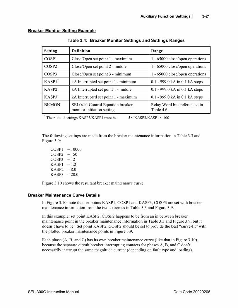
Auxiliary Function Settings 3-21
SEL-300G Instruction Manual Date Code 20020206
Breaker Monitor Setting Example
Table 3.4: Breaker Monitor Settings and Settings Ranges
Setting Definition Range
COSP1 Close/Open set point 1 - maximum 1 - 65000 close/open operations
COSP2 Close/Open set point 2 - middle 1 - 65000 close/open operations
COSP3 Close/Open set point 3 - minimum 1 - 65000 close/open operations
KASP1* kA Interrupted set point 1 - minimum 0.1 - 999.0 kA in 0.1 kA steps
KASP2 kA Interrupted set point 1 - middle 0.1 - 999.0 kA in 0.1 kA steps
KASP3* kA Interrupted set point 1 - maximum 0.1 - 999.0 kA in 0.1 kA steps
BKMON SELOGIC Control Equation breaker monitor initiation setting
Relay Word bits referenced in Table 4.6
* The ratio of settings KASP3/KASP1 must be: 5 ≤ KASP3/KASP1 ≤ 100
The following settings are made from the breaker maintenance information in Table 3.3 and Figure 3.9:
COSP1 = 10000 COSP2 = 150 COSP3 = 12 KASP1 = 1.2 KASP2 = 8.0 KASP3 = 20.0
Figure 3.10 shows the resultant breaker maintenance curve.
Breaker Maintenance Curve Details In Figure 3.10, note that set points KASP1, COSP1 and KASP3, COSP3 are set with breaker maintenance information from the two extremes in Table 3.3 and Figure 3.9.
In this example, set point KASP2, COSP2 happens to be from an in between breaker maintenance point in the breaker maintenance information in Table 3.3 and Figure 3.9, but it doesnt have to be. Set point KASP2, COSP2 should be set to provide the best curve-fit with the plotted breaker maintenance points in Figure 3.9.
Each phase (A, B, and C) has its own breaker maintenance curve (like that in Figure 3.10), because the separate circuit breaker interrupting contacts for phases A, B, and C dont necessarily interrupt the same magnitude current (depending on fault type and loading).

3-22 Auxiliary Function Settings
Date Code 20020206 SEL-300G Instruction Manual
DWG. M300G128
100%10,000
1000
2
3
4
5
6789
100
2
3
4
5
6789
10
2
3
4
5
6789
1 2 3 4 5 6 7 8 9 5040302010
Num
ber
of C
lose
/Ope
n O
pera
tions
kA Interrupted per Operation
.5
KASP1=1.2COSP1=10000
COSP2=150KASP2=8.0
COSP3=12KASP3=20.0

Auxiliary Function Settings 3-23
SEL-300G Instruction Manual Date Code 20020206
Figure 3.10: SEL-300G Relay Breaker Maintenance Curve for a 13.8 kV Circuit Breaker
In Figure 3.10 note that the breaker maintenance curve levels off horizontally below set point KASP1, COSP1. This is the close/open operation limit of the circuit breaker (COSP1 = 10000), regardless of interrupted current value.
Also, note that the breaker maintenance curve falls vertically above set point KASP3, COSP3. This is the maximum interrupted current limit of the circuit breaker (KASP3 = 20.0 kA). If the interrupted current is greater than setting KASP3, the interrupted current is accumulated as a current value equal to setting KASP3.
Operation of SELOGIC Control Equation Breaker Monitor Initiation Setting BKMON The SELOGIC Control Equation breaker monitor initiation setting BKMON in Table 3.4 determines when the breaker monitor reads in current values (Phases A, B, and C) for the breaker maintenance curve (see Figure 3.10) and the breaker monitor accumulated currents/trips [see BRE Command (Breaker Monitor Data) in Section 10: Serial Port Communications and Commands].
The BKMON setting looks for a rising edge (logical 0 to logical 1 transition) as the indication to read in current values. The acquired current values are then applied to the breaker maintenance curve and the breaker monitor accumulated currents/trips (see references in previous paragraph).
In the factory default settings, the SELOGIC Control Equation breaker monitor initiation setting is set:
BKMON = TRIP1 (TRIP1 is the logic output of Figure 4.6)
Refer to Figure 3.11. When BKMON asserts (Relay Word bit TRIP1 goes from logical 0 to logical 1), the breaker monitor reads in the current values and applies them to the breaker monitor maintenance curve and the breaker monitor accumulated currents/trips.
As detailed in Figure 3.11, the breaker monitor actually reads in the current values 0.75 cycles after the assertion of BKMON. This helps especially if an instantaneous trip occurs. The instantaneous element trips when the fault current reaches its pickup setting level. The fault current may still be climbing to its full value and then levels off. The 0.75-cycle delay on reading in the current values allows time for the fault current to level off.
BKMONDWG: M300G129
read incurrent values
risingedge
0.75 cyc
Figure 3.11: Operation of SELOGIC Control Equation Breaker Monitor Initiation Setting
Interpretation of the breaker monitor data is discussed in Section 8: Monitoring and Metering Functions.

3-24 Auxiliary Function Settings
Date Code 20020206 SEL-300G Instruction Manual
OPTOISOLATED INPUT DEBOUNCE TIMERS Figure 3.12 and Figure 3.13 show the resultant Relay Word bits that follow corresponding optoisolated inputs for the different SEL-300G Relay models. The figures show examples of energized and deenergized optoisolated inputs and corresponding Relay Word bit states. To assert an input, apply rated control voltage to the appropriate terminal.
The optoisolated inputs in Figure 3.12 and Figure 3.13 operate similarly.
RelayWordBits
energized
deenergized
States
RelayWord Bit
IN102
IN101
logical 1
logical 0
(-)
(+)
open
closed
Input StatesOptoisolated
Inputs
Opto-isolated
States
ExampleSwitch
DWG: M300G130
DebounceBuilt-in
Timers
open
closed
IN104 deenergized
IN103 energized
logical 0
logical 1
open
open
IN106
IN105
deenergized
deenergized
logical 0
logical 0
IN106D
IN105D
IN104D
IN103D
IN102D
IN101D
IN101D
IN105
IN106
IN103
IN104
IN101
IN102IN102D
IN103D
IN104D
IN105D
IN106D
Figure 3.12: Example Operation of Optoisolated Inputs IN101 Through IN106 (All Models)
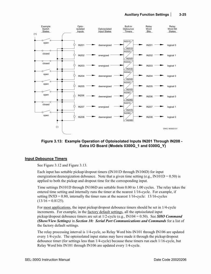
Auxiliary Function Settings 3-25
SEL-300G Instruction Manual Date Code 20020206
RelayWordBits
energized
deenergized
States
RelayWord Bit
IN202
IN201
logical 1
logical 0
(-)
(+)
open
closed
Input StatesOptoisolated
Inputs
Opto-isolated
States
ExampleSwitch
DWG. M300G131
DebounceBuilt-in
Timers
open
closed
IN204 deenergized
IN203 energized
logical 0
logical 1
open
open
IN206
IN205
deenergized
deenergized
logical 0
logical 0
IN206D
IN205D
IN204D
IN203D
IN202D
IN201D
IN201D
IN205
IN206
IN203
IN204
IN201
IN202IN202D
IN203D
IN204D
IN205D
IN206D
energized
deenergizedopen
closed
IN208
IN207
IN208D
IN207D
IN207D
IN208D
IN208
IN207 logical 1
logical 0
Figure 3.13: Example Operation of Optoisolated Inputs IN201 Through IN208 - Extra I/O Board (Models 0300G_1 and 0300G_Y)
Input Debounce Timers See Figure 3.12 and Figure 3.13.
Each input has settable pickup/dropout timers (IN101D through IN106D) for input energization/deenergization debounce. Note that a given time setting (e.g., IN101D = 0.50) is applied to both the pickup and dropout time for the corresponding input.
Time settings IN101D through IN106D are settable from 0.00 to 1.00 cycles. The relay takes the entered time setting and internally runs the timer at the nearest 1/16-cycle. For example, if setting IN5D = 0.80, internally the timer runs at the nearest 1/16-cycle: 13/16-cycles (13/16 = 0.8125).
For most applications, the input pickup/dropout debounce timers should be set in 1/4-cycle increments. For example, in the factory default settings, all the optoisolated input pickup/dropout debounce timers are set at 1/2-cycle (e.g., IN104 = 0.50). See SHO Command (Show/View Settings) in Section 10: Serial Port Communications and Commands for a list of the factory default settings.
The relay processing interval is 1/4-cycle, so Relay Word bits IN101 through IN106 are updated every 1/4-cycle. The optoisolated input status may have made it through the pickup/dropout debounce timer (for settings less than 1/4-cycle) because these timers run each 1/16-cycle, but Relay Word bits IN101 through IN106 are updated every 1/4-cycle.

3-26 Auxiliary Function Settings
Date Code 20020206 SEL-300G Instruction Manual
If more than 1 cycle of debounce is needed, run Relay Word bit INn (n = 101 through 106) through a SELOGIC Control Equation variable timer and use the output of the timer for input functions.
Input Functions Optoisolated inputs IN101 through IN106 receive their function by how their corresponding Relay Word bits IN101 through IN106 are used in SELOGIC Control Equations.
Factory Settings Example
DWG: M300G076
52a
(+)
IN102
(-)
GeneratorMain Breaker
52a
GeneratorField Breaker
IN101SEL-300G
Figure 3.14: Circuit Breaker Auxiliary Contacts Connected to Optoisolated Inputs IN101and IN102
The functions for input IN101 is described in the following discussions.
Input IN101 Relay Word bit IN101 is used in the factory settings for the SELOGIC Control Equation circuit breaker status setting:
52A = IN101
Connect input IN101 to a 52a circuit breaker auxiliary contact.
If a 52b circuit breaker auxiliary contact is connected to input IN101, the setting is changed to:
52A = !IN101 [!IN101 = NOT(IN101)]
The pickup/dropout timer for input IN1 (IN1D) is set at
IN1D = 0.5 cycles
to provide input energization/deenergization debounce.
Using Relay Word bit IN101 for the circuit breaker status setting 52A does not prevent using Relay Word bit IN101 in other SELOGIC Control Equation settings.

Auxiliary Function Settings 3-27
SEL-300G Instruction Manual Date Code 20020206
SER TRIGGER SETTINGS AND ALIAS SETTINGS
SER Triggering The relay triggers (generates) an entry in the SER report for a change of state of any one of the elements listed in the SER1, SER2, SER3, and SER4 trigger settings. The factory default settings are:
SER1 = 51NT 50N1T 51CT 51VT 64G1T 64G2T SV3 81D1 81D1T 81D2 81D2T 51N 50N1 51C 51V 64G1 64G2 INAD INADT
SER2 = DP3 LB1 RB1 LT3 TRGTR BCW IN101 IN102 TRIP1 TRIP2 TRIP3 TRIP4 BNDT 24C2T 32P1T 24C2 32P1 SV4 SV2T
SER3 = 24D1 24D1T 46Q1 46Q1T 60LOP BNDA 32P2 32P2T SWING OOS OOST
SER4 = 0
The elements are Relay Word bits referenced in Table 9.3. The relay monitors each element in the SER lists every 1/4 cycle. If an element changes state, the relay time-tags the changes in the SER. For example, setting SER1 contains:
Time-overcurrent element pickups (51N and 51V)
Instantaneous overcurrent element (50N1)
Thus, any time one of these overcurrent elements picks up or drops out, the relay time-tags the change in the SER.
The relay adds a message to the SER to indicate power up or settings change (to active setting group) conditions:
Relay newly powered up or settings changed
Each entry in the SER includes SER row number, date, time, element name or alias, and element state.
Making SER Trigger Settings Enter up to 24 element names in each of the SER settings via the SET R command. See Table 4.6 for references to valid relay element (Relay Word bit) names. See the SET R command in Table 6.1 and corresponding Settings Sheets at the end of Section 6: Enter Relay Settings. Use either spaces or commas to delimit the elements. For example, if you enter setting SER1 as:
SER1 = 51NT, 50N1T,, 51CT, 51VT 64G1T,
The relay displays the setting as:
SER1 = 51NT 50N1T 51CT 51VT 64G1T
The relay can monitor up to 96 elements in the SER (24 in each of SER1, SER2, SER3, and SER4).

3-28 Auxiliary Function Settings
Date Code 20020206 SEL-300G Instruction Manual
Alias Settings Associated with the relay SER function is a capability called Alias naming. Using this function, you can rename up to 40 Relay Word bits, changing the way they are represented in the SER report. In addition to changing the Relay Word bit name, you can also assign the state names used when the Relay Word bit is asserted and deasserted.
To rename a Relay Word bit with an ALIASn setting, use SET R to access the settings. For each ALIASn setting, enter the Relay Word bit name, a space, then the new name, a space, the text to display when the bit asserts, a space, then the text to display when the Relay Word bit deasserts. Each of the text strings can be up to 15 characters. If a space is desired within the text string, use an underscore ( _ ) instead. Do not use the characters ' ? , = " : / ; \ in a text string; they are treated as spaces.
As an example, you could set ALIAS1 as follows:
ALIAS1 = IN101 GEN_MAIN_BKR CLOSED OPENED
SER = IN101
With these settings, the SER function would record the date and time of each assertion and deassertion of the IN101 Relay Word bit in the SER record. The record could look like this:
GENERATOR Date: 01/30/00 Time: 10:20:45.872 TERMINAL FID=SEL-300G-R207-V31H425XX4X-Z001001-D20000217 CID=04B0 # DATE TIME ELEMENT STATE 2 01/30/00 10:20:24.807 GEN_MAIN_BKR CLOSED 1 01/30/00 10:30:30.828 GEN_MAIN_BKR OPENED =>
Figure 3.15: Example Sequential Events Recorder (SER) Event Report
For more information regarding the SER reports, see Section 11: Event Reports and SER Functions.
If you do set an alias, be sure to enter the Relay Word bit name (not the new alias name) in one of the SER1 - SER4 settings. If the Relay Word bit name is not entered in an SER1 - SER4 setting, stated changes for that Relay Word bit will not be recorded, even though the Relay Word bit has an alias.
If you do not wish to use an alias setting, set ALIASn = NA.
Date Code 20020206 SEL-300G Instruction Manual
TABLE OF CONTENTS
SECTION 4: SELOGIC® CONTROL EQUATIONS ...............................4-1
Introduction ...................................................................................................................................4-1 SELOGIC Control Equation Overview ..........................................................................................4-1 Relay Word Bits............................................................................................................................4-1
Relay Word Bit Operation Example Neutral Time-Overcurrent Element 51NT...............4-2 Neutral Time-Overcurrent Element 51NT Pickup Indication .......................................4-2 Neutral Time-Overcurrent Element 51NT Time Out Indication...................................4-2 Neutral Time-Overcurrent Element 51NT Reset Indication .........................................4-2 Relay Word Bit Application Examples Neutral Time-Overcurrent Element
51NT......................................................................................................................4-3 Other Relay Word Bits..........................................................................................................4-3
SELOGIC Control Equations .........................................................................................................4-3 SELOGIC Control Equation Operators ..................................................................................4-4
SELOGIC Control Equation Rising Edge Operator, / ....................................................4-4 SELOGIC Control Equation Falling Edge Operator, \ ...................................................4-4 SELOGIC Control Equation Parentheses Operator, ( ) ..................................................4-5 SELOGIC Control Equation NOT Operator, !................................................................4-5
Example of NOT Operator, !, Applied to Single Element ....................................4-5 Example of NOT Operator, !, Applied to Multiple Elements (within
parentheses) ...................................................................................................4-6 All SELOGIC Control Equations Must Be Set.......................................................................4-7
Set SELOGIC Control Equations Directly to 1 or 0 .......................................................4-7 SELOGIC Control Equation Limitations................................................................................4-7
Nondedicated SELOGIC Control Equation Variable Settings .......................................................4-8 Latch Control Switch Settings ......................................................................................................4-9
Latch Control Switch Application Ideas .............................................................................4-10 Local/Remote Generator Shutdown Setting Example ........................................................4-10
Use Local Bit LB1 or Remote Bit RB1 to Shut Down the Generator.........................4-11 Latch Control Switch States Retained.................................................................................4-11
Power Loss ..................................................................................................................4-11 Settings Change or Active Setting Group Change ......................................................4-11
NOTE: Make Latch Control Switch Settings with Care....................................................4-11 Trip Logic ...................................................................................................................................4-12
Set Trip................................................................................................................................4-13 Unlatch Trip ........................................................................................................................4-14
Generator Tripping......................................................................................................................4-14 Generator Main Circuit Breaker Trip, TR1 ........................................................................4-14 Generator Field Breaker Trip, TR2.....................................................................................4-15 Prime Mover Trip, TR3.......................................................................................................4-16 Generator Lockout Relay Trip, TR4 ...................................................................................4-17 Factory Default Tripping Logic ..........................................................................................4-18
Generator Fault, Prolonged System Fault, and Inadvertent Energization ...................4-18 Generator Abnormal Operating Conditions and Manual Trips...................................4-18 Generator Main Circuit Breaker Tripping Settings.....................................................4-19 Generator Field Circuit Breaker Tripping Settings .....................................................4-19
ii SELOGIC® Control Equations
Date Code 20020206 SEL-300G Instruction Manual
Prime Mover Tripping Settings ...................................................................................4-20 Generator Lockout Relay Tripping Settings ...............................................................4-20
Program Output Contacts for Tripping ...............................................................................4-21 Close Logic .................................................................................................................................4-21
Set Close..............................................................................................................................4-22 Unlatch Close ......................................................................................................................4-22 Settings Example.................................................................................................................4-23
Set Close......................................................................................................................4-23 Unlatch Close ..............................................................................................................4-23
Defeat the Close Logic........................................................................................................4-24 Program an Output Contact for Closing..............................................................................4-24
Synchronism Checking Function (Models 0300G2 and 0300G3)..............................................4-24 Element Description............................................................................................................4-24
Functional Description ................................................................................................4-24 Setting Descriptions ....................................................................................................4-25 Relay Word Bits ..........................................................................................................4-27
Setting Calculation ..............................................................................................................4-27 Information Needed.....................................................................................................4-27 Recommendations .......................................................................................................4-28 Manually Refine the 25RCF Setting While the Generator is in Service.....................4-31 Synch-Check Supervised Closing ...............................................................................4-33
Element Operating Characteristics......................................................................................4-34 ER Control Equation...................................................................................................................4-36 Output Contact Control ...............................................................................................................4-37
Factory Settings Example....................................................................................................4-37 Operation of Output Contacts for Different Output Contact Types....................................4-38
Output Contacts OUT101 Through OUT107 (All Models) and OUT201 Through OUT212 ................................................................................................4-38
ALARM Output Contact .............................................................................................4-38 Local Control Switches...............................................................................................................4-41
Local Control Switch Types................................................................................................4-42 ON/OFF Switch...........................................................................................................4-42 OFF/MOMENTARY Switch ......................................................................................4-42 ON/OFF/MOMENTARY Switch ...............................................................................4-43
Factory Settings Examples ..................................................................................................4-44 Additional Local Control Switch Application Ideas...........................................................4-45 Local Control Switch States Retained.................................................................................4-45
Power Loss ..................................................................................................................4-45 Settings Change or Active Setting Group Change ......................................................4-45
Remote Control Switches............................................................................................................4-46 Remote Bit Application Ideas .............................................................................................4-46 Remote Bit States Not Retained When Power is Lost ........................................................4-47 Remote Bit States Retained When Settings Changed or Active Setting Group
Changed.......................................................................................................................4-47 Front-Panel Display Configuration .............................................................................................4-47
Traditional Indicating Panel Meters....................................................................................4-47 Traditional Indicating Panel Meters Replaced with Rotating Meter Display.....................4-47 Traditional Indicating Panel Lights.....................................................................................4-48
Circuit Breaker Status Indication ................................................................................4-49 Traditional Indicating Panel Lights Replaced with Rotating Text Display ........................4-49

SELOGIC® Control Equations iii
SEL-300G Instruction Manual Date Code 20020206
General Operation of Rotating Text Display Settings ........................................................4-50 Factory Settings Examples ..................................................................................................4-50
Main Circuit Breaker Status Indication.......................................................................4-50 Circuit Breaker Closed ........................................................................................4-50 Circuit Breaker Open...........................................................................................4-51
Additional Settings Examples .............................................................................................4-51 Display Only One Message .........................................................................................4-51
Circuit Breaker Closed ........................................................................................4-51 Circuit Breaker Open...........................................................................................4-51
Continually Display a Message ...................................................................................4-52 Inadvertent Energization .............................................................................................................4-52 Breaker Failure Protection ..........................................................................................................4-54 Breaker Failure Protection With Breaker Flashover Detection ..................................................4-56 Application Examples .................................................................................................................4-57
Performance Alarms............................................................................................................4-57 Protection Element Alarms..........................................................................................4-58
Volts/Hertz Overexcitation Alarms, 24D1T and 24C2 .......................................4-58 Unbalance Current Alarm, 46Q1T and 46Q2......................................................4-58 Loss-of-Potential, 60LOP....................................................................................4-58
Generator Off-Frequency Accumulator Protection .....................................................4-58 Circuit Breaker Wear Monitor ....................................................................................4-58 DC Voltage Monitor....................................................................................................4-59 Relay Self-Test Alarms ...............................................................................................4-59
Relay Word Bits (used in SELOGIC Control Equations) ............................................................4-62
TABLES Table 4.1: SELOGIC Control Equation Operators (listed in processing order)........................................4-4 Table 4.2: Association Between Tripping Settings and Controlled Apparatus ......................................4-13 Table 4.3: Correspondence Between Local Control Switch Positions and Label Settings ....................4-42 Table 4.4: Correspondence Between Local Control Switch Types and Required Label Settings..........4-43 Table 4.5: Relay Self-Tests .....................................................................................................................4-60 Table 4.6: SEL-300G Relay Word Bits ..................................................................................................4-62 Table 4.7: Relay Word Bit Definitions for Table 4.6 .............................................................................4-64
FIGURES Figure 4.1: Result of Falling Edge Operator on a Deasserting Underfrequency Element........................4-5 Figure 4.2: SELOGIC Control Equation Variable Timer Logic.................................................................4-8 Figure 4.3: Traditional Latching Relay.....................................................................................................4-9 Figure 4.4: Latch Control Switches Drive Latch Bits LT1 Through LT16 ..............................................4-9 Figure 4.5: Latch Control Switch to Shut Down Generator ...................................................................4-10 Figure 4.6: Trip Logic .............................................................................................................................4-12 Figure 4.7: Minimum Trip Duration Timer Operation (see Figure 4.6) .................................................4-13 Figure 4.8: Close Logic...........................................................................................................................4-21 Figure 4.9: Synch-Check Function 25RCF Setting Examples ................................................................4-29 Figure 4.10: Synch-Check Function Voltage Elements ..........................................................................4-34

iv SELOGIC® Control Equations
Date Code 20020206 SEL-300G Instruction Manual
Figure 4.11: Synch-Check Function Voltage Element Characteristic ....................................................4-34 Figure 4.12 Synch-Check Function Slip Elements .................................................................................4-35 Figure 4.13: Synch-Check Function Angle Elements .............................................................................4-35 Figure 4.14: Breaker Close Failure Logic Diagram................................................................................4-36 Figure 4.15: Synch-Check Function Angle Characteristics ....................................................................4-36 Figure 4.16: Logic Flow for Example Output Contact Operation (All Models) ....................................4-39 Figure 4.17: Logic Flow for Example Output Contact Operation - Extra I/O Board (Model
0300G_1 and 0300G_Y) ..............................................................................................4-40 Figure 4.18: Local Control Switches Drive Local Bits LB1 Through LB16..........................................4-41 Figure 4.19: Local Control Switch Configured as an ON/OFF Switch ..................................................4-42 Figure 4.20: Local Control Switch Configured as an OFF/MOMENTARY Switch..............................4-43 Figure 4.21: Local Control Switch Configured as an ON/OFF/MOMENTARY Switch.......................4-43 Figure 4.22: Configured GEN SHUTDOWN Switch Drives Local Bit LB1 .........................................4-44 Figure 4.23: Remote Control Switches Drive Remote Bits RB1 Through RB16...................................4-46 Figure 4.24: Traditional Panel Light Installations ..................................................................................4-49 Figure 4.25: Rotating Text Display Replaces Traditional Panel Light Installations ..............................4-49 Figure 4.26: Inadvertent Energization Logic Diagram ...........................................................................4-54 Figure 4.27: Generator/Breaker Topology Where SEL-300G1 Relay Offers Breaker Failure
Protection......................................................................................................................4-55 Figure 4.28: SEL-300G Relay Breaker Failure Logic ............................................................................4-55 Figure 4.29: Generator/Breaker Topology Where SEL-300G1 Relay Offers Breaker Failure and
Breaker Flashover Protection .......................................................................................4-56 Figure 4.30: SEL-300G Relay Breaker Failure Plus Breaker Flashover Protection Logic ....................4-57

SELOGIC® Control Equations 4-1
SEL-300G Instruction Manual Date Code 20000616
SECTION 4: SELOGIC® CONTROL EQUATIONS
INTRODUCTION This section describes SELOGIC® Control Equations and their various applications within the SEL-300G Relay. Specific topics include:
• General Operation of Relay Word Bits • SELOGIC Control Equations • SELOGIC Control Equation Latch Function • SEL-300G Relay Trip Logic • Generator Tripping With Example Settings • SEL-300G Relay Close Logic • Event Triggering • Output Contact Control • Local and Remote Control Switch Settings • Front-Panel Display Configuration Settings • Inadvertent Energization Logic With Example Settings • Breaker Failure Protection • Relay Self-Testing Functions • Additional SELOGIC Control Equation Application Examples
Tables at the end of this section summarize all of the Relay Word bits available for making SELOGIC Control Equations.
Note: Do not AND any of the out-of-step (78) element Relay Word bits with any of the loss-of-field (40) element Relay Word bits.
SELOGIC CONTROL EQUATION OVERVIEW SELOGIC Control Equations combine relay protection and control elements with logic operators to create custom protection and control schemes. This section shows how to set the protection and control elements (Relay Word bits) in the SEL Control Equations.
RELAY WORD BITS Most of the protection and control element logic outputs shown in the various figures in Section 2: Relay Element Settings and Section 3: Auxiliary Function Settings are Relay Word bits (labeled as such in the figures). Each Relay Word bit has a label name and can be in either of the following states:
1 (logical 1) or 0 (logical 0)
Logical 1 represents an element being picked up, timed out, or otherwise asserted.
4-2 SELOGIC® Control Equations
Date Code 20000616 SEL-300G Instruction Manual
Logical 0 represents an element being dropped out or otherwise deasserted. A complete listing of Relay Word bits and their descriptions are referenced in Table 4.6.
Relay Word Bit Operation Example Neutral Time-Overcurrent Element 51NT
As an example of protection element operation via the logic output of Relay Word bits, consider a neutral time-overcurrent element. Refer to neutral time-overcurrent element 51NT in Figure 2.25 in Section 2: Relay Element Settings. The following Relay Word bits are the logic outputs of the neutral time-overcurrent element:
51N indication that the neutral current magnitude is above the level of the neutral time-overcurrent pickup setting 51NP
51NT indication that the neutral time-overcurrent element has timed out on its curve 51NR indication that the neutral time-overcurrent element is fully reset
Neutral Time-Overcurrent Element 51NT Pickup Indication
If the neutral current is below the level of the neutral time-overcurrent pickup setting 51NP, Relay Word bit 51N is in the following state:
51N = 0 (logical 0)
If the neutral current is at or above the level of the neutral time-overcurrent pickup setting 51NP, Relay Word bit 51N is in the following state:
51N = 1 (logical 1)
If the neutral current is at or above the level of the neutral time-overcurrent pickup setting 51NP, neutral time-overcurrent element 51NT is either timing on its curve or is already timed out.
Neutral Time-Overcurrent Element 51NT Time Out Indication
If neutral time-overcurrent element 51NT is not timed out on its curve, Relay Word bit 51NT is in the following state:
51NT = 0 (logical 0)
If neutral time-overcurrent element 51NT is timed out on its curve, Relay Word bit 51NT is in the following state:
51NT = 1 (logical 1)
Neutral Time-Overcurrent Element 51NT Reset Indication
If neutral time-overcurrent element 51NT is not fully reset, Relay Word bit 51NR is in the following state:
51NR = 0 (logical 0)
If neutral time-overcurrent element is fully reset, Relay Word bit 51NR is in the following state:
51NR = 1 (logical 1)

SELOGIC® Control Equations 4-3
SEL-300G Instruction Manual Date Code 20000616
If neutral time-overcurrent element 51NT is not fully reset, the element is either:
• timing on its curve • already timed out • timing to reset (one-cycle reset or electromechanical emulation
see setting 51NRS)
Relay Word Bit Application Examples Neutral Time-Overcurrent Element 51NT
Common uses for Relay Word bits 51N, 51NT, and 51NR:
51N testing (e.g., assign to an output contact for pickup testing) trip unlatch logic 51NT trip logic 51NR used in testing (e.g., assign to an output contact for reset indication)
Other Relay Word Bits
The preceding example was for a neutral time-overcurrent element, demonstrating Relay Word bit operation for pickup, time-out, and reset conditions. Other Relay Word bits (e.g., those for definite-time overcurrent elements, voltage elements, frequency elements) behave similarly in their assertion or deassertion to logical 1 or logical 0, respectively. The time-overcurrent elements (like the preceding neutral time-overcurrent element example) are unique because they have a Relay Word bit (e.g., 51NR) that asserts for the reset state of the element.
Relay Word bits are used in SELOGIC Control Equations, which are explained in the following subsection.
SELOGIC CONTROL EQUATIONS Many of the protection and control element logic inputs shown in the various figures in Section 2: Relay Element Settings and Section 3: Auxiliary Function Settings are SELOGIC Control Equations (labeled SELOGIC Settings in most of the figures). SELOGIC Control Equations are set with combinations of Relay Word bits to accomplish such functions as:
• tripping circuit breakers • assigning functions to optoisolated inputs • operating output contacts • torque-controlling protection elements • switching active setting groups
Traditional or advanced custom schemes can be created with SELOGIC Control Equations.
Note: Do not AND any of the out-of-step (78) element Relay Word bits with any of the loss-of-field (40) element Relay Word bits. The 78 and 40 elements are updated by the relay on opposite half power system cycles. Therefore, the logical AND of the two element types may not operate as expected.

4-4 SELOGIC® Control Equations
Date Code 20000616 SEL-300G Instruction Manual
SELOGIC Control Equation Operators
SELOGIC Control Equation settings use logic similar to Boolean algebra logic, combining Relay Word bits together using one or more of the six SELOGIC Control Equation operators listed in Table 4.1.
Table 4.1: SELOGIC Control Equation Operators (listed in processing order)
Operator Logic Function / rising edge detect \ falling edge detect
( ) parentheses ! NOT * AND + OR
Operators in a SELOGIC Control Equation setting are processed in the order shown in Table 4.1.
SELOGIC Control Equation Rising Edge Operator, /
The rising edge operator, /, is applied to individual Relay Word bits only not to groups of elements within parentheses. For example, the SELOGIC Control Equation event report generation setting uses rising edge operators:
ER = /24C2 + /32P1 + /46Q2 +
The Relay Word bits in this factory setting example are:
24C2 Measured generator volts/hertz equal to or above the pickup setting for the 24C2 volts/hertz element (see Figure 2.13).
32P1 Measured real power less than the pickup setting for the 32P1 reverse/low-forward power element (see Figure 2.15).
46Q2 Measured negative-sequence current greater than the pickup setting for the 46Q2 negative-sequence time-overcurrent element (see Figure 2.19).
When setting ER sees a logical 0 to logical 1 transition, the relay generates an event report if it is not already generating a report that encompasses the new transition. The rising edge operators cause a logical 0 to logical 1 transition (thus triggering a new report) each time one of the protection elements asserts. Using these settings, the relay triggers a new event report each time any of the protection elements assert, if the relay is not already recording an event report.
SELOGIC Control Equation Falling Edge Operator, \
The falling edge operator, \, is applied to individual Relay Word bits only not to groups of elements within parentheses. The falling edge operator, \, operates similarly to the rising edge operator, but looks for Relay Word bit deassertion (element going from logical 1 to logical 0). The falling edge operator, \, in front of a Relay Word bit sees this logical 1 to logical 0 transition as a falling edge and asserts to logical 1 for one processing interval.

SELOGIC® Control Equations 4-5
SEL-300G Instruction Manual Date Code 20000616
For example, suppose the SELOGIC Control Equation event report generation setting is set with the detection of the falling edge of an underfrequency element:
ER = ... + \81D1T
When frequency goes above the corresponding pickup level 81D1P, Relay Word bit 81D1T deasserts and an event report is generated (if the relay is not already generating a report that encompasses the new transition). This allows a recovery from an underfrequency condition to be observed. Figure 4.1 demonstrates the action of the falling edge operator, \, on the underfrequency element in setting ER.
DWG: M300G160
one processing interval
\81D1T
81D1T
Figure 4.1: Result of Falling Edge Operator on a
Deasserting Underfrequency Element
SELOGIC Control Equation Parentheses Operator, ( )
More than one set of parentheses ( ) can be used in a SELOGIC Control Equation setting. For example, the following SELOGIC Control Equation setting has two sets of parentheses:
SV7 = (SV7 + IN103 + TRIP1) * (50H1 + 50R1 + 52A)
In the above example, the logic within the parentheses is processed first and then the two parentheses resultants are ANDed together. The above example is from Figure 4.28 in this section. Parentheses cannot be nested (parentheses within parentheses) in a SELOGIC Control Equation setting.
SELOGIC Control Equation NOT Operator, !
The NOT operator, !, is applied to a single Relay Word bit and also to multiple elements (within parentheses). Following are examples of both.
Example of NOT Operator, !, Applied to Single Element
The internal circuit breaker status logic in the SEL-300G Relay operates on 52a circuit breaker auxiliary contact logic. The SELOGIC Control Equation circuit breaker status setting is labeled 52A.
When a circuit breaker is closed, the 52a circuit breaker auxiliary contact is closed. When a circuit breaker is open, the 52a contact is open.

4-6 SELOGIC® Control Equations
Date Code 20000616 SEL-300G Instruction Manual
The opposite is true for a 52b circuit breaker auxiliary contact. When a circuit breaker is closed, the 52b circuit breaker auxiliary contact is open. When the circuit breaker is open, the 52b contact is closed.
If a 52a contact is connected to optoisolated input IN101, the SELOGIC Control Equation circuit breaker status setting 52A is set:
52A = IN101
Conversely, if a 52b contact is connected to optoisolated input IN101, the SELOGIC Control Equation circuit breaker status setting 52A is set:
52A = !IN101 [=NOT(IN101)]
With a 52b contact connected, if the circuit breaker is closed, the 52b contact is open and input IN101 is deenergized [IN101 = 0 (logical 0)]:
52A = !IN101 = NOT(IN101) = NOT(0) = 1
Thus, the SELOGIC Control Equation circuit breaker status setting 52A sees a closed circuit breaker.
With a 52b contact connected, if the circuit breaker is open, the 52b contact is closed and input IN101 is energized [IN101 = 1 (logical 1)]:
52A = !IN101 = NOT(IN101) = NOT(1) = 0
Thus, the SELOGIC Control Equation circuit breaker status setting 52A sees an open circuit breaker.
Example of NOT Operator, !, Applied to Multiple Elements (within parentheses)
The SELOGIC Control Equation trip unlatch setting could be set as follows:
ULTR1 = !(51N + 50L)
Refer also to Trip Logic in this section.
In this setting example, the unlatch condition comes true only when both the 51N (neutral time-overcurrent element pickup indication) and 50L (lowest phase overcurrent element pickup indication) Relay Word bits deassert:
ULTR1 = !(51N + 50L) = NOT(51N + 50L)
As stated previously, the logic within the parentheses is performed first. In this example, the states of Relay Word bits 51N and 50L are ORed together. Then the NOT operator is applied to the logic resultant from the parentheses.
If either one of 51N or 50L is still asserted [e.g., 51N = 1 (logical 1)], the unlatch condition is not true:
ULTR1 = NOT(51N + 50L) = NOT(1 + 0) = NOT(1) = 0
SELOGIC® Control Equations 4-7
SEL-300G Instruction Manual Date Code 20000616
If both 51N and 50L are deasserted [i.e., 51N = 0 and 50L = 0 (logical 0)], the unlatch condition is true:
ULTR1 = NOT(51N + 50L) = NOT(0 + 0) = NOT(0) = 1
and the trip condition can unlatch, subject to other conditions in the trip logic (see Figure 4.6).
All SELOGIC Control Equations Must Be Set
All SELOGIC Control Equations must be set one of the following ways (they cannot be blank):
• single Relay Word bit (e.g., 52A = IN101) • combination of Relay Word bits (e.g., TR1 = SV3 + SV4 + 46Q2T + 81D1T + 81D2T) • directly to logical 1 (e.g., 46QTC = 1) • directly to logical 0 (e.g., SV6 = 0)
Set SELOGIC Control Equations Directly to 1 or 0
SELOGIC Control Equations can be set directly to:
1 (logical 1) or 0 (logical 0)
instead of with Relay Word bits. If a SELOGIC Control Equation setting is set directly to 1, it is always asserted/on/enabled. If a SELOGIC Control Equation setting is set equal to 0, it is always deasserted/off/disabled.
SELOGIC Control Equation Limitations
Any single SELOGIC Control Equation setting is limited to 17 Relay Word bits that can be combined together with the SELOGIC Control Equation operators listed in Table 4.1. If this limit must be exceeded, use a SELOGIC Control Equation variable (SELOGIC Control Equation settings SV1 through SV12) as an intermediate setting step.
For example, assume that a trip equation (such as SELOGIC Control Equation trip setting TR1) needs more than 17 Relay Word bits in its equation setting. Instead of placing all Relay Word bits into TR1, program some of them into the SELOGIC Control Equation setting SV1. Next use the resultant SELOGIC Control Equation variable output (Relay Word bit SV1) in the SELOGIC Control Equation trip setting TR1.
Note that the SELOGIC Control Equation variables (SELOGIC Control Equation settings SV1 through SV16) are processed after the trip equation (SELOGIC Control Equation trip setting TR). Thus, any tripping via Relay Word bits SV1 through SV16 is delayed by 1/4 cycle. For most applications, this is probably of no consequence.
All the SELOGIC Control Equation settings have a combined limit of approximately 330 Relay Word bits that can be combined together with the SELOGIC Control Equation operators listed in Table 4.1. SELOGIC Control Equation settings that are set directly to 1 (logical 1) or 0 (logical 0) also have to be included in this combined limit of 330 Relay Word bits each such setting counted as one Relay Word bit.

4-8 SELOGIC® Control Equations
Date Code 20000616 SEL-300G Instruction Manual
As the relay saves its settings, it calculates the percentage of SELOGIC Control Equation capability used by the settings you entered. The relay reports this percentage as SCEUSE = xx.x as the settings are saved and when you execute the SHO 1 or SHO 2 commands. The SCEUSE value provides a measure of the relay control equation capability being used. The remainder (100 - SCEUSE)% is available for future expansion.
NONDEDICATED SELOGIC CONTROL EQUATION VARIABLE SETTINGS In addition to the torque-control equations, tripping, and output contact control equations, each relay setting group is equipped with 16 nondedicated SELOGIC Control Equation variables. Each of these variables is equipped with a time-delay pickup timer, a time-delay dropout timer, and an independent definition equation. The ESV setting allows you to select and set only the SELOGIC Control Equation variables required by your application.
Enable SELOGIC Control Equations (0 - 16) ESV = 7
Set ESV equal to the total number of SELOGIC Control Equation variables required by your application.
SELOGIC Control Equation
SV1 = 27V1 * 40Z2
SV1 Pickup Time (0.00 - 3000.00 s) SV1PU = 0.25
SV1 Dropout Time (0.00 - 3000.00 s) SV1DO = 0.03
The SV1PU setting defines the SV1T Relay Word bit time-delay pickup time. SV1T asserts SV1PU seconds after the SV1 SELOGIC Control Equation result becomes a logical 1. The SV1DO setting defines the SV1T Relay Word bit time-delay dropout time. Once SV1T is asserted, it remains asserted for SV1DO seconds after the SV1 SELOGIC Control Equation result becomes a logical 0. The SV1 SELOGIC Control Equation is the logical definition of the SV1 Relay Word bit. Make the SELOGIC Control Equation setting by combining Relay Word bits and logical operators, as shown in the examples earlier in this section. Figure 4.2 illustrates the SELOGIC Control Equation variable timer logic.
Settings SV2 - SV16 operate similarly when enabled.
DWG: M300G078
RelayWordBits
SVn
SVnTSVn
SELOGICSetting SVnPU
SVnDO
Figure 4.2: SELOGIC Control Equation Variable Timer Logic
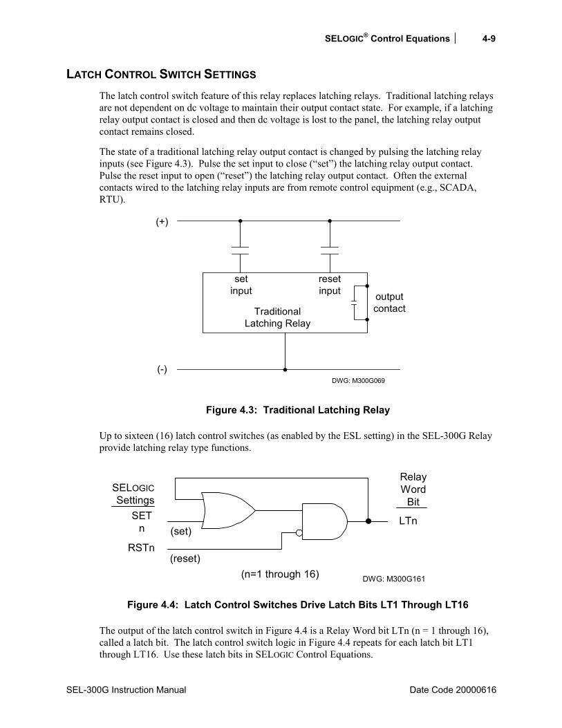
SELOGIC® Control Equations 4-9
SEL-300G Instruction Manual Date Code 20000616
LATCH CONTROL SWITCH SETTINGS The latch control switch feature of this relay replaces latching relays. Traditional latching relays are not dependent on dc voltage to maintain their output contact state. For example, if a latching relay output contact is closed and then dc voltage is lost to the panel, the latching relay output contact remains closed.
The state of a traditional latching relay output contact is changed by pulsing the latching relay inputs (see Figure 4.3). Pulse the set input to close (set) the latching relay output contact. Pulse the reset input to open (reset) the latching relay output contact. Often the external contacts wired to the latching relay inputs are from remote control equipment (e.g., SCADA, RTU).
DWG: M300G069
(+)
(-)
resetinput
TraditionalLatching Relay
setinput output
contact
Figure 4.3: Traditional Latching Relay
Up to sixteen (16) latch control switches (as enabled by the ESL setting) in the SEL-300G Relay provide latching relay type functions.
DWG: M300G161
LTn
SELOGICSettings
SETn
RSTn(set)
(reset)(n=1 through 16)
RelayWord
Bit
Figure 4.4: Latch Control Switches Drive Latch Bits LT1 Through LT16
The output of the latch control switch in Figure 4.4 is a Relay Word bit LTn (n = 1 through 16), called a latch bit. The latch control switch logic in Figure 4.4 repeats for each latch bit LT1 through LT16. Use these latch bits in SELOGIC Control Equations.
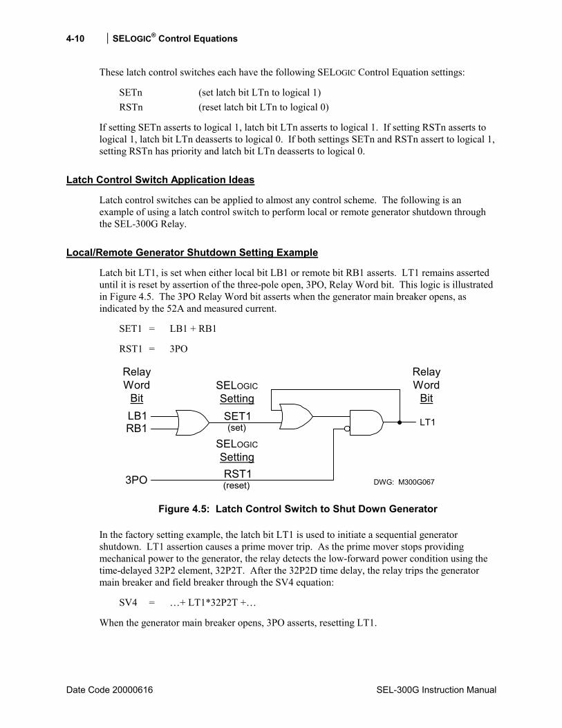
4-10 SELOGIC® Control Equations
Date Code 20000616 SEL-300G Instruction Manual
These latch control switches each have the following SELOGIC Control Equation settings:
SETn (set latch bit LTn to logical 1) RSTn (reset latch bit LTn to logical 0)
If setting SETn asserts to logical 1, latch bit LTn asserts to logical 1. If setting RSTn asserts to logical 1, latch bit LTn deasserts to logical 0. If both settings SETn and RSTn assert to logical 1, setting RSTn has priority and latch bit LTn deasserts to logical 0.
Latch Control Switch Application Ideas
Latch control switches can be applied to almost any control scheme. The following is an example of using a latch control switch to perform local or remote generator shutdown through the SEL-300G Relay.
Local/Remote Generator Shutdown Setting Example
Latch bit LT1, is set when either local bit LB1 or remote bit RB1 asserts. LT1 remains asserted until it is reset by assertion of the three-pole open, 3PO, Relay Word bit. This logic is illustrated in Figure 4.5. The 3PO Relay Word bit asserts when the generator main breaker opens, as indicated by the 52A and measured current.
SET1 = LB1 + RB1
RST1 = 3PO
DWG: M300G067
SET1
RelayWord
Bit
(reset)
(set)LB1 LT1RB1
3PO
SELOGICSetting
SELOGICSettingRST1
RelayWord
Bit
Figure 4.5: Latch Control Switch to Shut Down Generator
In the factory setting example, the latch bit LT1 is used to initiate a sequential generator shutdown. LT1 assertion causes a prime mover trip. As the prime mover stops providing mechanical power to the generator, the relay detects the low-forward power condition using the time-delayed 32P2 element, 32P2T. After the 32P2D time delay, the relay trips the generator main breaker and field breaker through the SV4 equation:
SV4 = + LT1*32P2T +
When the generator main breaker opens, 3PO asserts, resetting LT1.
SELOGIC® Control Equations 4-11
SEL-300G Instruction Manual Date Code 20000616
Use Local Bit LB1 or Remote Bit RB1 to Shut Down the Generator
Pulse local bit LB1 using the CNTRL front-panel pushbutton.
Remote bits (Relay Word bits RB1 through RB16) are operated through the serial port. See
Figure 4.23 and Section 10: Serial Port Communications and Commands for more information on remote bits.
Latch Control Switch States Retained
Power Loss
The states of the latch bits (LT1 through LT16) are retained if power to the relay is lost and then restored. If a latch bit is asserted (e.g., LT2 = logical 1) when power is lost, it comes back asserted (LT2 = logical 1) when power is restored. If a latch bit is deasserted (e.g., LT3 = logical 0) when power is lost, it comes back deasserted (LT3 = logical 0) when power is restored. This feature makes the latch bit feature behave the same as traditional latching relays. In a traditional installation, if power is lost to the panel, the latching relay output contact position remains unchanged.
Settings Change or Active Setting Group Change
If individual settings are changed (for the active setting group or one of the other setting groups) or the active setting group is changed, the states of the latch bits (Relay Word bits LT1 through LT16) are retained, much like in the preceding Power Loss explanation.
If individual settings are changed for a setting group other than the active setting group, there is no interruption of the latch bits (the relay is not momentarily disabled).
If the individual settings change or the active setting group change causes a change in SELOGIC Control Equation settings SETn or RSTn (n = 1 through 16), the retained states of the latch bits can be changed subject to the newly enabled settings SETn or RSTn.
NOTE: Make Latch Control Switch Settings with Care
The latch bit states are stored in nonvolatile memory so they can be retained during power loss, settings change, or active setting group change. The nonvolatile memory is rated for a finite number of writes for all cumulative latch bit state changes. Exceeding the limit can result in an EEPROM self-test failure. An average of 150 cumulative latch bit state changes per day can be made for a 25-year relay service life.
This requires that SELOGIC Control Equation settings SETn and RSTn for any given latch bit LTn (n = 1 through 16; see Figure 4.4) be set with care. Settings SETn and RSTn must not result in continuous cyclical operation of latch bit LTn. Use timers to qualify conditions set in settings SETn and RSTn. If any optoisolated inputs IN101 through IN108 are used in settings SETn and RSTn, the inputs have their own debounce timer that can help in providing the necessary time qualification (see Section 3: Auxiliary Function Settings).

4-12 SELOGIC® Control Equations
Date Code 20000616 SEL-300G Instruction Manual
TRIP LOGIC The SEL-300G Relay provides tripping logic to operate up to four external devices. Table 4.2 shows the normal association between tripping settings and the apparatus controlled. Figure 4.6 illustrates the tripping logic.
TR1
TripSeal-In
andUnlatchLogic
0
TDURD
Rising EdgeDetect
OR-1
Minumum TripDuration Timer
Unlatch Trip
RelayWord
Bit
TRIP1
SELOGICTrip Setting
OC1
TAR R
ULTR1TARGET
RESETPushbutton
Serial PortCommands
SELOGICSetting
TR2
TripSeal-In
andUnlatchLogic
0
TDURD
Rising EdgeDetect
OR-2
Minumum TripDuration Timer
Unlatch Trip
RelayWord
Bit
TRIP2
SELOGICTrip Setting
OC2
TAR R
ULTR2TARGET
RESETPushbutton
Serial PortCommands
SELOGICSetting
TR3
TripSeal-In
andUnlatchLogic
0
TDURD
Rising EdgeDetect
OR-3
Minumum TripDuration Timer
Unlatch Trip
RelayWord
Bit
TRIP3
SELOGICTrip Setting
OC3
TAR R
ULTR3TARGET
RESETPushbutton
Serial PortCommands
SELOGICSetting
TR4
TripSeal-In
andUnlatchLogic
0
TDURD
Rising EdgeDetect
OR-4
Minumum TripDuration Timer
Unlatch Trip
RelayWord
Bit
TRIP4
SELOGICTrip Setting
TAR R
ULTR4TARGET
RESETPushbutton
Serial PortCommands
SELOGICSetting
TRIP1TRIP2TRIP3TRIP4
TRIP
RelayWord
Bit
DWG: 300G068
RelayWordBits
Figure 4.6: Trip Logic
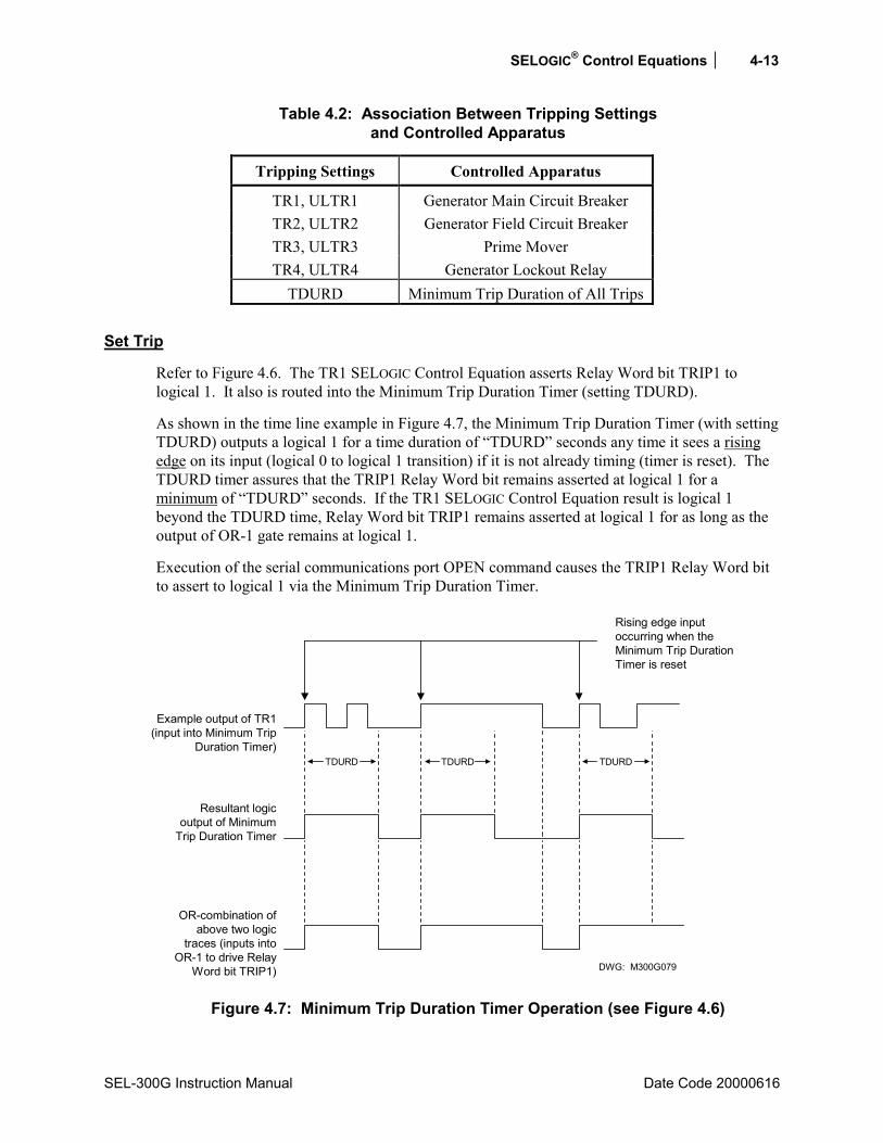
SELOGIC® Control Equations 4-13
SEL-300G Instruction Manual Date Code 20000616
Table 4.2: Association Between Tripping Settings and Controlled Apparatus
Tripping Settings Controlled Apparatus
TR1, ULTR1 Generator Main Circuit Breaker TR2, ULTR2 Generator Field Circuit Breaker TR3, ULTR3 Prime Mover TR4, ULTR4 Generator Lockout Relay
TDURD Minimum Trip Duration of All Trips
Set Trip
Refer to Figure 4.6. The TR1 SELOGIC Control Equation asserts Relay Word bit TRIP1 to logical 1. It also is routed into the Minimum Trip Duration Timer (setting TDURD).
As shown in the time line example in Figure 4.7, the Minimum Trip Duration Timer (with setting TDURD) outputs a logical 1 for a time duration of TDURD seconds any time it sees a rising edge on its input (logical 0 to logical 1 transition) if it is not already timing (timer is reset). The TDURD timer assures that the TRIP1 Relay Word bit remains asserted at logical 1 for a minimum of TDURD seconds. If the TR1 SELOGIC Control Equation result is logical 1 beyond the TDURD time, Relay Word bit TRIP1 remains asserted at logical 1 for as long as the output of OR-1 gate remains at logical 1.
Execution of the serial communications port OPEN command causes the TRIP1 Relay Word bit to assert to logical 1 via the Minimum Trip Duration Timer.
DWG: M300G079
Rising edge inputoccurring when theMinimum Trip DurationTimer is reset
Example output of TR1(input into Minimum Trip
Duration Timer)TDURD TDURD TDURD
OR-combination ofabove two logic
traces (inputs intoOR-1 to drive Relay
Word bit TRIP1)
Resultant logicoutput of Minimum
Trip Duration Timer
Figure 4.7: Minimum Trip Duration Timer Operation (see Figure 4.6)
4-14 SELOGIC® Control Equations
Date Code 20000616 SEL-300G Instruction Manual
Unlatch Trip
Once Relay Word bit TRIP is asserted to logical 1, it remains asserted at logical 1 until all the following conditions come true:
• Minimum Trip Duration Timer stops timing (logic output of the TDURD timer goes to logical 0)
• Output of TR1 gate deasserts to logical 0 • One of the following occurs:
− SELOGIC Control Equation setting ULTR1 asserts to logical 1, or − the front-panel TARGET RESET button is pressed, or − the TAR R (Target Reset) command is executed via the serial port.
The front-panel TARGET RESET button or the TAR R (Target Reset) serial port command primarily is used during testing. Use these to force the TRIP1 Relay Word bit to logical 0 if test conditions are such that setting ULTR1 does not assert to logical 1 to deassert the TRIP1 Relay Word bit automatically.
TRIP2 through TRIP4 operate similarly to TRIP1, as shown in Figure 4.6. The Relay Word bit TRIP is the OR condition of the four primary TRIP1 bits.
GENERATOR TRIPPING
Generator Main Circuit Breaker Trip, TR1
It is necessary to trip the Generator Main Circuit Breaker to isolate the generator from the system in response to many situations. The SEL-300G Relay elements and logic used to detect each of the conditions are summarized in the table below.
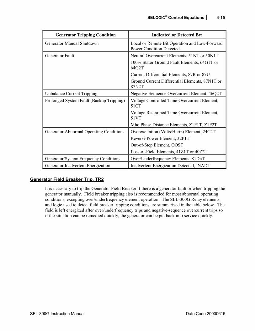
SELOGIC® Control Equations 4-15
SEL-300G Instruction Manual Date Code 20000616
Generator Tripping Condition Indicated or Detected By:
Generator Manual Shutdown Local or Remote Bit Operation and Low-Forward Power Condition Detected
Generator Fault Neutral Overcurrent Elements, 51NT or 50N1T 100% Stator Ground Fault Elements, 64G1T or 64G2T Current Differential Elements, 87R or 87U Ground Current Differential Elements, 87N1T or 87N2T
Unbalance Current Tripping Negative-Sequence Overcurrent Element, 46Q2T Prolonged System Fault (Backup Tripping) Voltage Controlled Time-Overcurrent Element,
51CT Voltage Restrained Time-Overcurrent Element, 51VT Mho Phase Distance Elements, Z1P1T, Z1P2T
Generator Abnormal Operating Conditions Overexcitation (Volts/Hertz) Element, 24C2T Reverse Power Element, 32P1T Out-of-Step Element, OOST Loss-of-Field Elements, 41Z1T or 40Z2T
Generator/System Frequency Conditions Over/Underfrequency Elements, 81DnT Generator Inadvertent Energization Inadvertent Energization Detected, INADT
Generator Field Breaker Trip, TR2
It is necessary to trip the Generator Field Breaker if there is a generator fault or when tripping the generator manually. Field breaker tripping also is recommended for most abnormal operating conditions, excepting over/underfrequency element operation. The SEL-300G Relay elements and logic used to detect field breaker tripping conditions are summarized in the table below. The field is left energized after over/underfrequency trips and negative-sequence overcurrent trips so if the situation can be remedied quickly, the generator can be put back into service quickly.

4-16 SELOGIC® Control Equations
Date Code 20000616 SEL-300G Instruction Manual
Field Breaker Tripping Condition Indicated or Detected By:
Generator Manual Shutdown Local or Remote Bit Operation and Low-Forward Power Condition Detected
Generator Fault Neutral Overcurrent Elements, 51NT or 50N1T 100% Stator Ground Fault Elements, 64G1T or 64G2T Current Differential Elements, 87R or 87U Ground Current Differential Elements, 87N1T or 87N2T
Prolonged System Fault (Backup Tripping) Voltage Controlled Time-Overcurrent Element, 51CT Voltage Restrained Time-Overcurrent Element, 51VT Mho Phase Distance Elements, Z1P1T, Z1P2T
Generator Abnormal Operating Conditions Overexcitation (Volts/Hertz) Element, 24C2T Reverse Power Element, 32P1T Loss-of-Field Elements, 41Z1T or 40Z2T
Generator Inadvertent Energization Inadvertent Energization Detected, INADT
Prime Mover Trip, TR3
A prime mover trip is performed first during a manual generator shutdown. The prime mover is also tripped in the event of a generator fault. Typically, the prime mover is not tripped in response to abnormal operating conditions. As with the field breaker trips, this is so that the generator can be reconnected quickly if the problem is corrected, avoiding the need for a time-consuming prime mover restart.
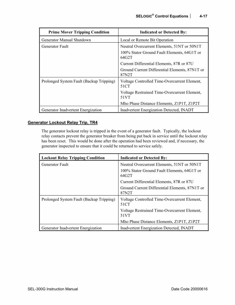
SELOGIC® Control Equations 4-17
SEL-300G Instruction Manual Date Code 20000616
Prime Mover Tripping Condition Indicated or Detected By:
Generator Manual Shutdown Local or Remote Bit Operation Generator Fault Neutral Overcurrent Elements, 51NT or 50N1T
100% Stator Ground Fault Elements, 64G1T or 64G2T Current Differential Elements, 87R or 87U Ground Current Differential Elements, 87N1T or 87N2T
Prolonged System Fault (Backup Tripping) Voltage Controlled Time-Overcurrent Element, 51CT Voltage Restrained Time-Overcurrent Element, 51VT Mho Phase Distance Elements, Z1P1T, Z1P2T
Generator Inadvertent Energization Inadvertent Energization Detected, INADT
Generator Lockout Relay Trip, TR4
The generator lockout relay is tripped in the event of a generator fault. Typically, the lockout relay contacts prevent the generator breaker from being put back in service until the lockout relay has been reset. This would be done after the operation had been reviewed and, if necessary, the generator inspected to ensure that it could be returned to service safely. Lockout Relay Tripping Condition Indicated or Detected By: Generator Fault Neutral Overcurrent Elements, 51NT or 50N1T
100% Stator Ground Fault Elements, 64G1T or 64G2T Current Differential Elements, 87R or 87U Ground Current Differential Elements, 87N1T or 87N2T
Prolonged System Fault (Backup Tripping) Voltage Controlled Time-Overcurrent Element, 51CT Voltage Restrained Time-Overcurrent Element, 51VT Mho Phase Distance Elements, Z1P1T, Z1P2T
Generator Inadvertent Energization Inadvertent Energization Detected, INADT

4-18 SELOGIC® Control Equations
Date Code 20000616 SEL-300G Instruction Manual
Factory Default Tripping Logic
Review of the tables above shows that each of the controlled devices has tripping conditions in common. For instance, all of the devices are tripped in response to a generator fault. To simplify the relay settings, we have assigned nondedicated SELOGIC Control Equation variables to collect conditions that are used in more than one tripping equation. These settings are summarized and described below.
Generator Fault, Prolonged System Fault, and Inadvertent Energization
SELOGIC Control Equation Variable 3 is used to indicate generator faults, prolonged system faults, and inadvertent generator energization:
SV3 = 64G1T + 64G2T + 51NT + 50N1T + 51CT + 51VT + INADT* * the terms . . . +87R + 87U should be added to the SV3 variable to obtain percentage restrained
differential element tripping. The terms . . . +87N1T + 87N2T should be added to the SV3 variable to obtain ground current differential tripping. The terms . . . 21P1T + 21P2T should be added to obtain Zone 1 and Zone 2 phase mho distance tripping.
SELOGIC Control Equation Term
Asserts to Indicate:
64G1T Generator stator ground fault detected by neutral overvoltage. 64G2T Generator stator ground fault detected by third-harmonic voltage
differential. 51NT + 50N1T Ground fault detected by neutral time-overcurrent element or
neutral definite-time overcurrent element. 51CT + 51VT Prolonged system fault detected by voltage controlled phase
time-overcurrent or voltage restrained phase time-overcurrent. INADT Inadvertent generator energization detected.
Generator Abnormal Operating Conditions and Manual Trips
SELOGIC Control Equation Variable 4 is used to indicate generator abnormal operating conditions and manual trips:
SV4 = 24C2T + 32P1T + 40Z1T + 40Z2T + LT1*32P2T
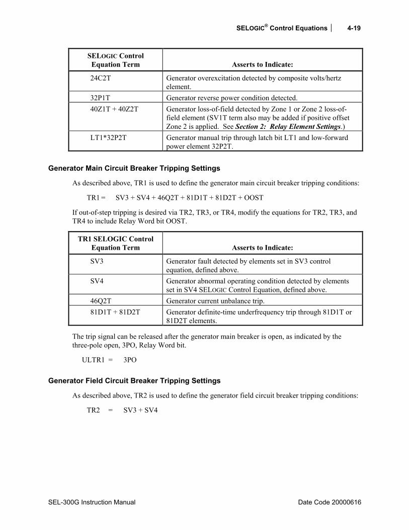
SELOGIC® Control Equations 4-19
SEL-300G Instruction Manual Date Code 20000616
SELOGIC Control Equation Term
Asserts to Indicate:
24C2T Generator overexcitation detected by composite volts/hertz element.
32P1T Generator reverse power condition detected. 40Z1T + 40Z2T Generator loss-of-field detected by Zone 1 or Zone 2 loss-of-
field element (SV1T term also may be added if positive offset Zone 2 is applied. See Section 2: Relay Element Settings.)
LT1*32P2T Generator manual trip through latch bit LT1 and low-forward power element 32P2T.
Generator Main Circuit Breaker Tripping Settings
As described above, TR1 is used to define the generator main circuit breaker tripping conditions:
TR1 = SV3 + SV4 + 46Q2T + 81D1T + 81D2T + OOST
If out-of-step tripping is desired via TR2, TR3, or TR4, modify the equations for TR2, TR3, and TR4 to include Relay Word bit OOST.
TR1 SELOGIC Control Equation Term
Asserts to Indicate:
SV3 Generator fault detected by elements set in SV3 control equation, defined above.
SV4 Generator abnormal operating condition detected by elements set in SV4 SELOGIC Control Equation, defined above.
46Q2T Generator current unbalance trip. 81D1T + 81D2T Generator definite-time underfrequency trip through 81D1T or
81D2T elements.
The trip signal can be released after the generator main breaker is open, as indicated by the three-pole open, 3PO, Relay Word bit.
ULTR1 = 3PO
Generator Field Circuit Breaker Tripping Settings
As described above, TR2 is used to define the generator field circuit breaker tripping conditions:
TR2 = SV3 + SV4
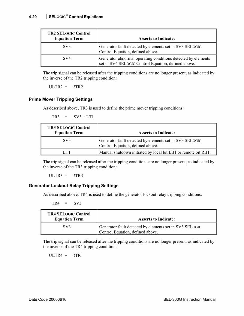
4-20 SELOGIC® Control Equations
Date Code 20000616 SEL-300G Instruction Manual
TR2 SELOGIC Control Equation Term
Asserts to Indicate:
SV3 Generator fault detected by elements set in SV3 SELOGIC Control Equation, defined above.
SV4 Generator abnormal operating conditions detected by elements set in SV4 SELOGIC Control Equation, defined above.
The trip signal can be released after the tripping conditions are no longer present, as indicated by the inverse of the TR2 tripping condition:
ULTR2 = !TR2
Prime Mover Tripping Settings
As described above, TR3 is used to define the prime mover tripping conditions:
TR3 = SV3 + LT1
TR3 SELOGIC Control Equation Term
Asserts to Indicate:
SV3 Generator fault detected by elements set in SV3 SELOGIC Control Equation, defined above.
LT1 Manual shutdown initiated by local bit LB1 or remote bit RB1.
The trip signal can be released after the tripping conditions are no longer present, as indicated by the inverse of the TR3 tripping condition:
ULTR3 = !TR3
Generator Lockout Relay Tripping Settings
As described above, TR4 is used to define the generator lockout relay tripping conditions:
TR4 = SV3
TR4 SELOGIC Control Equation Term
Asserts to Indicate:
SV3 Generator fault detected by elements set in SV3 SELOGIC Control Equation, defined above.
The trip signal can be released after the tripping conditions are no longer present, as indicated by the inverse of the TR4 tripping condition:
ULTR4 = !TR
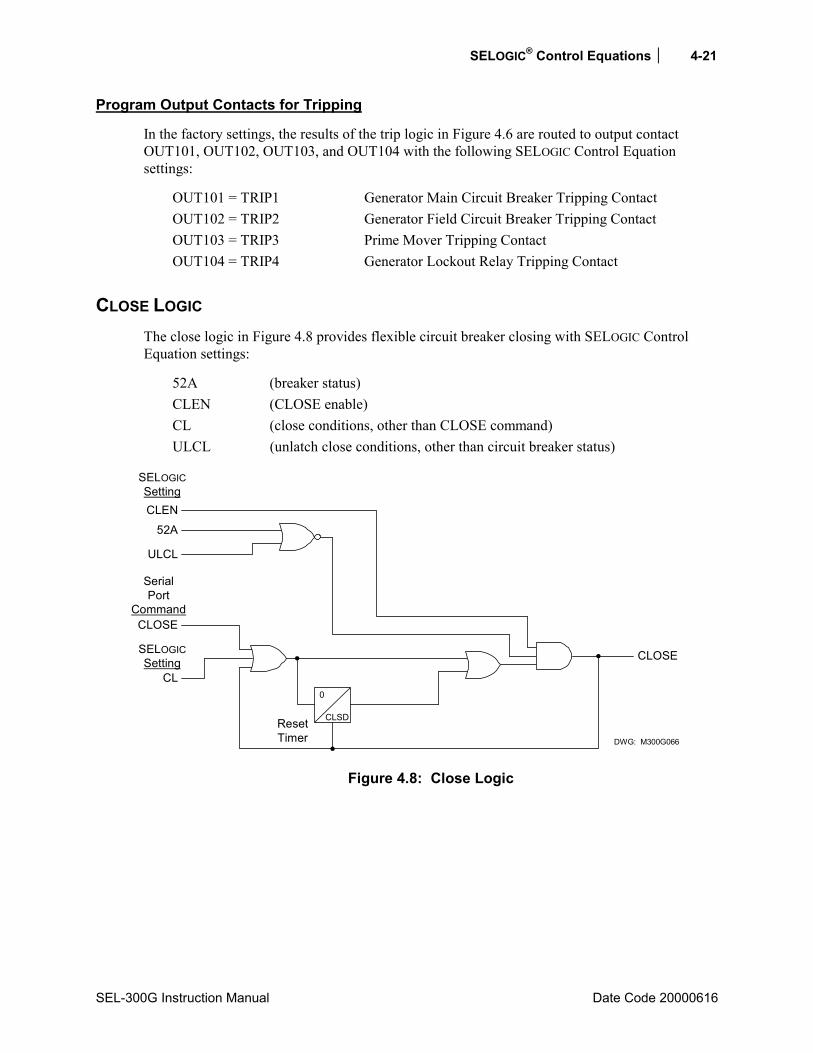
SELOGIC® Control Equations 4-21
SEL-300G Instruction Manual Date Code 20000616
Program Output Contacts for Tripping
In the factory settings, the results of the trip logic in Figure 4.6 are routed to output contact OUT101, OUT102, OUT103, and OUT104 with the following SELOGIC Control Equation settings:
OUT101 = TRIP1 Generator Main Circuit Breaker Tripping Contact OUT102 = TRIP2 Generator Field Circuit Breaker Tripping Contact OUT103 = TRIP3 Prime Mover Tripping Contact OUT104 = TRIP4 Generator Lockout Relay Tripping Contact
CLOSE LOGIC The close logic in Figure 4.8 provides flexible circuit breaker closing with SELOGIC Control Equation settings:
52A (breaker status) CLEN (CLOSE enable) CL (close conditions, other than CLOSE command) ULCL (unlatch close conditions, other than circuit breaker status)
ULCL
CLOSE
SerialPort
Command
CL
CLOSE
52ACLEN
SELOGICSetting
0
CLSD
DWG: M300G066
SELOGICSetting
ResetTimer
Figure 4.8: Close Logic

4-22 SELOGIC® Control Equations
Date Code 20000616 SEL-300G Instruction Manual
Set Close
If all the following are true:
• The unlatch close condition is not asserted (ULCL = logical 0), • The circuit breaker is open (52A = logical 0), and • Closing is enabled (CLEN = logical 1)
Then the CLOSE Relay Word bit can be asserted to logical 1 if any one of the following occurs:
• The serial communications port CLOSE command is executed, • SELOGIC Control Equation setting CL goes from logical 0 to logical 1 (rising edge
transition).
If a serial port CLOSE command is executed or CL goes from logical 0 to logical 1 while the CLEN SELOGIC Control Equation is logical 0, the relay waits for CLSD close dwell time seconds for CLEN to assert. If CLEN asserts before CLSD expires, the CLOSE Relay Word bit asserts to logical 1. If CLEN does not assert before CLSD expires, the CLOSE Relay Word bit does not assert and the logic is reset. This logic permits the CLEN SELOGIC Control Equation to supervise relay initiated closes. Assign CLEN to follow an optoisolated input connected to a synchronism checking relay or the synch-check function built into SEL-0300G2/300G3 Relays to ensure that the generator and system are in synchronism before the breaker close is allowed.
Unlatch Close
If the CLOSE Relay Word bit is asserted at logical 1, it stays asserted at logical 1 until one of the following occurs:
• The unlatch close condition asserts (ULCL = logical 1), • The circuit breaker closes (52A = logical 1), or • The close enable deasserts (CLEN = logical 0).
SELOGIC® Control Equations 4-23
SEL-300G Instruction Manual Date Code 20000616
Settings Example
Suggested settings for the close logic SELOGIC Control Equation settings are:
52A = IN101 CL = LB2 Permits front-panel close operations via Local bit LB2 CLEN = !SV6T Prevents a second close for 30 seconds, AND with 25C or
25A1 for synch-check supervised closing ULCL = TRIP + SV5T Unlatches CLOSE if relay trips or if CLOSE is asserted for
more than 1 second • • •
SV5 = CLOSE SV5PU = 1.00 SV5DO = 0.00 SV6 = CLOSE SV6PU = 0.00 SV6DO = 30.00
The factory setting for the Close Dwell Timer setting is:
CLSD = 0.00 s
A longer CLSD timer setting would be applied if the close logic should remain armed for a time while the generator is sychronized.
See the Settings Sheets at the end of Section 6: Enter Relay Settings for setting ranges.
Set Close
With the suggested settings, SELOGIC Control Equation setting CL is set with local bit LB2. Local bit LB2 closes directly (operates as a manual close switch via the front panel). See Local Control Switches in this section and Front-Panel Local Control in Section 9: Front-Panel Operation for more information on local control.
Unlatch Close
With the suggested settings, SELOGIC Control Equation setting ULCL is set by the TRIP Relay Word bit. This prevents the CLOSE Relay Word bit from being asserted any time the TRIP Relay Word bit is asserted (TRIP takes priority). See Trip Logic in this section.
SELOGIC Control Equation setting 52A is set with optoisolated input IN101. Input IN101 is connected to a 52a circuit breaker auxiliary contact. When a closed circuit breaker condition is detected, the CLOSE Relay Word bit is deasserted to logical 0. Setting 52A can handle a 52a or 52b circuit breaker auxiliary contact connected to an optoisolated input.

4-24 SELOGIC® Control Equations
Date Code 20000616 SEL-300G Instruction Manual
Defeat the Close Logic
If SELOGIC Control Equation close enable setting CLEN is set with logical 0 (CLEN = 0), then the close logic is inoperable.
Program an Output Contact for Closing
In the factory settings, the result of the close logic in Figure 4.8 is routed to output contact OUT105 with the following SELOGIC Control Equation:
OUT105 = CLOSE
SYNCHRONISM CHECKING FUNCTION (MODELS 0300G2 AND 0300G3)
Element Description
Functional Description
A synchronism checking relay is usually used to verify that the generator frequency, voltage magnitude, and phase angle match the system frequency, voltage magnitude, and phase angle before allowing the generator breaker to be closed. The SEL-300G2 and SEL-300G3 Relays provide a built-in synchronism checking function. The relay measures system voltage using the VS voltage input, which you should connect to the secondary of a phase-to-ground or phase-to-phase connected VT on the system side of the generator circuit breaker. If a phase-to-phase connected VT is applied, it should be connected between A- and B-phase or between B- and C-phase. See Section 5: Installation for additional connection details.
The relay measures the system conditions through the VS input. The relay measures generator frequency using the VA or VAB input. Other generator voltage conditions are determined using the voltage selected by the SYNCP setting, set to match the VS input connection. If the slip frequency (frequency difference between the generator and system) is within settable bounds, both voltage magnitudes are within settable bounds, and the phase-angle difference is desirable, the relay synchronism check function can permit a CLOSE signal to be issued by the SEL-300G Relay or can close an output contact to supervise an external close condition.
The relay takes into account the breaker closing time and the present slip frequency to issue a close signal timed to have the system and generator at a settable angle difference when the breaker closes.
If a generator step-up transformer is connected between the generator terminals and the open generator breaker, the SEL-300G Relay can account for a ±30° phase shift introduced by the transformer connections without using auxiliary transformers.
In the event that the generator breaker is slow to close, the generator and system voltages might drift to a phase angle that is unsafe for closing before the breaker closes. In this event, the relay detects that the phase angle between the generator and system voltages is above a safe closing angle and can issue a breaker close failure signal to perform breaker failure tripping and protect the generator
SELOGIC® Control Equations 4-25
SEL-300G Instruction Manual Date Code 20000616
Setting Descriptions
Enable Synchronism Checking (Y, N) E25 = Y
Set E25 = Y to enable synchronism checking elements. If synchronism checking is not required, set E25 = N. When E25 = N, the 59VP, 59VS, GENVHI, GENVLO, GENFHI, GENFLO, VDIF, 25A1, 25A2, 25C, CFA, and BKRCF Relay Word bits are inactive and the following relay settings are hidden and do not need to be entered.
Synch-Check Phase (VA, VB, VC, VAB, VBC) SYNCP = VA
Set SYNCP to indicate which phase the synch voltage VT is connected to. You may use phase-to-ground or phase-to-phase connected VT, regardless of whether open-delta or four-wire wye VTs are used on the generator.
Voltage Window, Low Threshold (20.0 to 200.0 V) 25VLO = 58.3 Voltage Window, High Threshold (20.0 to 200.0 V) 25VHI = 69.7 Maximum Voltage Difference (OFF, 1.0 to 15.0%) 25VDIF = 3.3
The 25VLO and 25VHI settings define the acceptable system (VS) voltage magnitude window prior to closing the generator breaker. 25VHI must be a higher voltage value than 25VLO. The system and generator voltages must both be greater than 25VLO and less than 25VHI for the synch-check outputs to operate. The 25VDIF setting defines the maximum acceptable percentage magnitude difference between the system and generator voltages prior to closing the generator breaker.
Generator Voltage High Required (Y, N) GENV+ = Y
If your synchronization practice requires that the generator voltage be higher than the system voltage prior to closing the generator breaker, set GENV+ = Y. If not, set GENV+ = N.
Voltage Ratio Correction Factor (0.500 to 2.00) 25RCF = 1.000
Use the 25RCF setting to null minor differences between the system and generator voltage transformer ratios. Normally, the 25RCF setting should be very close to 1.000. Use the instructions below to determine whether a nonunity setting should be used in your application.
Minimum Slip Frequency (-1.00 to 0.99 Hz) 25SLO = 0.05 Maximum Slip Frequency (-0.99 to 1.00 Hz) 25SHI = 0.10
The 25SLO and 25SHI settings define the acceptable slip frequency between the system and the generator prior to closing the generator breaker. 25SHI must be greater than 25SLO. The SEL-300G Relay defines slip frequency greater than 0 Hz when the generator frequency is greater than the system frequency.
Transformer Compensation Angle (0, +30°, -30°) COMPA = 0
Use the COMPA setting to compensate for the phase angle shift introduced by a generator step-up transformer connected between the generator terminals and the open generator breaker. When there is no transformer, set COMPA = 0. When there is a transformer andthe system phase-neutral voltage phase angle leads the generator phase-neutral voltage
4-26 SELOGIC® Control Equations
Date Code 20020206 SEL-300G Instruction Manual
phase angle by 30°, set COMPA = -30°. When the system phase-neutral voltage phase angle lags the generator phase-neutral voltage phase angle by 30°, set COMPA = 30°.
Maximum Angle 1 (0 to 80°) 25ANG1 = 5
The 25ANG1 setting defines an acceptable generator breaker closing angle. The relay asserts the 25A1 Relay Word bit when the generator voltage is within 25ANG1 degrees of the system voltage if the other supervisory conditions also are met. When the breaker close time setting, TCLOSD, is nonzero, the relay accounts for the breaker time and present slip frequency to adjust the phase angles where 25A1 is asserted.
Maximum Angle 2 (0 to 80°) 25ANG2 = 15
The 25ANG2 setting also defines an acceptable generator breaker closing angle. The relay asserts the 25A2 Relay Word bit when the generator voltage is within 25ANG2 degrees of the system voltage if the other supervisory conditions also are met. The relay does not account for the breaker time or present slip frequency to adjust the phase angles where 25A2 is asserted; it is an absolute phase angle comparison.
Target Close Angle (-15 to +15°) CANGLE = -3
The CANGLE setting defines a target closing angle (positive angle indicates VS lagging SYNCP voltage). When the balance of supervisory conditions are satisfied (slip, voltage window, voltage difference) the synch-check function accounts for the present slip and the set TCLOSD time (if not equal to zero). The relay asserts the 25C Relay Word bit for 1/4 cycle to initiate a close. 25C assertion is timed so that, if the slip remains constant and the breaker closes in TCLOSD seconds, the breaker closes when the angle difference is equal to CANGLE.
Breaker Close Time (0.000 to 1.000 s) TCLOSD = 0.150
The TCLOSD setting predicts the amount of time that it will take for the generator main breaker to close, from the instant the SEL-300G Relay CLOSE contact closes, to the instant the breaker main contacts close. Enter a value that is as accurate as possible to obtain best performance of the 25C close initiating Relay Word bit.
Close Fail Angle (OFF, 3 to 120°) CFANGL = 30
If the relay initiates a closure using the 25C Relay Word bit, and the breaker has not closed when the phase angle difference between the generator and system reaches the CFANGL setting, the relay asserts the BKRCF breaker close failure Relay Word bit. This Relay Word bit typically would be used to close a relay output contact to energize the bus lockout relay. The bus lockout relay would trip all breakers connected to the bus, protecting the generator from the out-of-synchronism close.
Block Synch Check (SELOGIC Control Equation) BSYNCH = !3PO
The synch-check function is blocked when the BSYNCH SELOGIC Control Equation result equals logical 1. The function is allowed to operate when the BSYNCH SELOGIC Control Equation result equals logical 0. Typically, the BSYNCH SELOGIC Control Equation should be set so the function is blocked when the generator main circuit breaker is closed (!3PO). Other supervisory conditions may be added if your application requires.

SELOGIC® Control Equations 4-27
SEL-300G Instruction Manual Date Code 20000616
Relay Word BitsRelay Word Bit Function Description Typical Applications
59VP Generator Terminal Voltage Within Voltage Window
Indication, Testing
59VS System Voltage Within Voltage Window Indication, Testing GENVHI Generator Voltage Greater Than System
Voltage Indication, Testing
GENVLO Generator Voltage Less Than System Voltage
Indication, Testing
VDIF Generator and System Voltage Difference Within Acceptable Bounds
Indication, Testing
GENFHI Slip Frequency Greater Than 25SHI Setting
Indication, Testing
GENFLO Slip Frequency Less Than 25SLO Setting Indication, Testing SF Slip Frequency Within Acceptable Bounds Indication, Testing 25A1 Slip/Breaker-Time Compensated Phase
Angle Within 25ANG1 Setting Indication, Testing, Control
25A2 Uncompensated Phase Angle Within 25ANG2 Setting
Indication, Testing, Control
25C Initiate CLOSE to Match Target Close Angle
Indication, Testing, Control
CFA Close Failure Angle Condition Testing BKRCF Breaker Close Failed Control, Testing
Setting Calculation
Information Needed
CAUTION !
Synchronism checking requirements and practices vary widely for different prime mover types. Be sure to consult your prime mover manufacturers synchronism checking guidelines as you prepare these settings or severe equipment damage or loss of equipment life may result.
• Prime Mover Manufacturers Synchronization Guidelines. • Synch VT Connection and Transformer Ratio. • Generator VT Connection and Transformer Ratio. • Generator Breaker Closing Time. • Generator Step-Up Transformer Winding Turns Ratio and Connection (only required if the
transformer is connected between the generator VTs and the synch VT).
4-28 SELOGIC® Control Equations
Date Code 20000616 SEL-300G Instruction Manual
Recommendations
Set the SYNCP setting to indicate the phase(s) to which the synch-check voltage transformer is connected on the system side of the generator circuit breaker. For instance, if the synch VT is connected from A-phase to neutral, set SYNCP = VA. If the synch VT is connect from B-phase to C-phase, set SYNCP = VBC. The relay does not require that the synch VT be connected in the same manner that the generator VTs are. For instance, you can elect to use open-delta connected VTs on the generator (setting DELTA_Y = D) and a phase-to-neutral connected VT on the system. If a phase-to-phase connected VT is used on the system side, it must be connected B-phase to C-phase or A-phase to B-phase.
Use the 25VLO, 25VHI, 25VDIF, and GENV+ settings to define the voltage conditions under which the generator breaker may be closed safely. The 25VLO and 25VHI settings define an acceptable voltage magnitude window. A close is not permitted if the generator or system voltages are less than 25VLO or greater than 25VHI.
Make the 25VLO and 25VHI settings based on the secondary magnitude of VS. For instance, if a close is acceptable while the system voltage ranges from 90% to 105% of nominal, if the synch PT is connected phase-to-neutral and the nominal line-to-neutral voltage is 67 V secondary, then
25VLO = 0.9 ⋅ 67 V secondary = 60.3 V secondary 25VHI = 1.05 ⋅ 67 V secondary = 70.4 V secondary
When a phase-to-phase connected synch VT is used, the nominal phase-to-phase voltage would probably be approximately 120 V secondary, leading to
25VLO = 0.9 ⋅ 120 V secondary = 108 V secondary 25VHI = 1.05 ⋅ 120 V secondary = 126 V secondary
The 25VDIF setting defines a maximum acceptable percentage difference between the generator and system voltages. GENV+ defines whether the generator voltage must be greater than the system voltage. Setting 25VDIF = OFF disables this supervision and permits a close when both voltages are within the voltage window defined by 25VLO and 25VHI.
For instance, the generator and prime mover manufacturer may recommend that the generator voltage be between 0% and +3% of the system voltage when the generator breaker is closed. In that case, set 25VDIF = 3% and GENV+ = Y. If a close is permitted when the generator voltage is within ±5% of the system voltage, set 25VDIF = 5% and GENV+ = N.
The 25RCF setting compensates minor magnitude differences between the synch voltage and the generator voltage. Magnitude differences may be introduced by unmatched or slightly erroneous voltage transformer or step-up transformer ratios.
When there is no generator step-up transformer between the generator VTs and the synch VT, set 25RCF = 1.000, initially. You may wish to refine the setting using the procedure below after the relay is in service.
When there is a generator step-up transformer between the generator VTs and the synch VT, set 25RCF using the equation below:
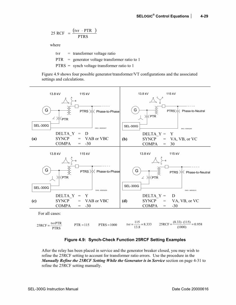
SELOGIC® Control Equations 4-29
SEL-300G Instruction Manual Date Code 20000616
( )PTRS
PTRtvrRCF25 ⋅=
where
tvr = transformer voltage ratio PTR = generator voltage transformer ratio to 1 PTRS = synch voltage transformer ratio to 1
Figure 4.9 shows four possible generator/transformer/VT configurations and the associated settings and calculations.
G
SEL-300G
Phase-to-Phase
DWG: M300G207
13.8 kV 115 kVa
c b
A
C
B
PTR
PTRS
DELTA_Y = D (a) SYNCP = VAB or VBC COMPA = -30
G
SEL-300G
Phase-to-Neutral
DWG: M300G208
13.8 kV 115 kVa
c b
AC
B
PTR
PTRS
DELTA_Y = Y (b) SYNCP = VA, VB, or VC COMPA = 30
G
SEL-300G
Phase-to-Phase
DWG: M300G209
13.8 kV 115 kVa
c b
A
C
B
PTR
PTRS
DELTA_Y = Y (c) SYNCP = VAB or VBC COMPA = -30
G
SEL-300G
Phase-to-Neutral
DWG: M300G210
13.8 kV 115 kVa
c b
A
C
B
PTRPTRS
DELTA_Y = D (d) SYNCP = VA, VB, or VC COMPA = -30
For all cases:
PTRSPTRtvrRCF25 ⋅=
115PTR =
1000PTRS =
333.88.13
115tvr ==
958.0)1000(
)115()33.8(RCF25 =⋅=
Figure 4.9: Synch-Check Function 25RCF Setting Examples
After the relay has been placed in service and the generator breaker closed, you may wish to refine the 25RCF setting to account for transformer ratio errors. Use the procedure in the Manually Refine the 25RCF Setting While the Generator is in Service section on page 4-31 to refine the 25RCF setting manually.

4-30 SELOGIC® Control Equations
Date Code 20000616 SEL-300G Instruction Manual
The 25SLO and 25SHI settings define the minimum and maximum acceptable slip frequency for a generator breaker close. 25SLO must be set less than 25SHI. The SEL-300G Relay defines the slip frequency positive when the generator frequency is higher than the system frequency.
Some large steam turbine generators require that a low, positive slip be present when the generator breaker is closed. Setting 25SLO = 0.05 Hz and 25SHI = 0.25 Hz might satisfy that requirement.
Diesel generators may require that a zero or negative slip be present. This tends to unload the machine shaft and crank briefly when the generator breaker closes. Setting 25SLO = -0.25 Hz and 25SHI = 0.0 Hz might satisfy this requirement.
The COMPA setting allows the relay to compensate for a transformer-introduced ±30° phase shift between the generator VTs and the synch VT. In most applications, the VTs will only have the open circuit breaker between them and in these cases, COMPA = 0°.
When a generator step-up transformer resides between the generator VTs and synch VT, examine the connections to determine the lead-lag relationship between the generator and system voltages. When the system voltage leads the generator voltage by 30°, set COMPA = -30. When the system voltage lags the generator voltage by 30°, set COMPA = 30.
The SEL-300G Relay synch-check function provides three methods to supervise internal and external close signals. Relay Word bits 25A1, 25A2, and 25C assert for different generator and system voltage phase angles, but all are supervised by the voltage magnitude and difference and slip frequency limits.
The relay uses two phase-angle calculations to control the 25A2, 25A1, and 25C Relay Word bits. The first phase-angle calculation is the absolute phase-angle difference between the generator and system voltages. The next phase-angle calculation adjusts the absolute phase-angle difference by an angle value that is the phase angle the system will travel through in TCLOSD seconds, assuming that the present slip frequency remains constant. This slip compensated phase angle predicts the phase-angle difference when the breaker closes if a close were issued at this instant and if the breaker closed in TCLOSD seconds.
The 25A2 Relay Word bit asserts when the absolute phase-angle difference is less than the 25ANG2 setting.
Relay Word bit 25A1 asserts when the slip-compensated phase-angle difference is less than the 25ANG1 setting.
The 25C Relay Word bit asserts when the slip-compensated phase-angle difference is equal to the CANGLE setting. When you would like to initiate a generator breaker close, timed so the phase-angle difference will equal the CANGLE setting, supervise the CLOSE initiation with the 25C Relay Word bit.
Settings for 25ANG1, 25ANG2, and CANGLE depend on the requirements of the application.
Set TCLOSD equal to the circuit breaker closing time in seconds. This value is used to calculate the slip-compensated phase-angle difference between the generator and system voltages, as described above. If there are interposing relays between the SEL-300G Relay CLOSE output and the circuit breaker close coil, add the operating time of these components to the breakers own closing time to calculate the TCLOSD setting.

SELOGIC® Control Equations 4-31
SEL-300G Instruction Manual Date Code 20000616
Large generators can sustain serious damage if the generator circuit breaker closes while there is a large phase-angle difference between the generator voltage and the system voltage. Synch-check relays help prevent this occurrence. However, if the circuit breaker is slow to close, the generator slip frequency can cause the generator voltage to rotate away from the system voltage, increasing the phase-angle difference to dangerous levels. At this point it is not possible to trip the slowly closing breaker; but if the breaker does close eventually, it could badly damage the generator or reduce its life. To prevent this, a breaker failure lockout signal can be used to clear the generator bus. This removes system voltage from the outboard side of the circuit breaker so if the breaker does close, it only energizes a dead bus.
The SEL-300G Relay synch-check function includes breaker slow close detection logic. If a circuit breaker close is initiated by the relay, the breaker close failure logic is armed. If the breaker closes, the 3PO Relay Word bit deasserts and the logic is disarmed. If the breaker does not close and the generator voltage rotates to greater than the close failure angle, CFANGL, the relay asserts the BKRCF circuit breaker close failure Relay Word bit. This Relay Word bit would be applied to trip the bus lockout relay. If some type of control failure occurs that prevents the generator breaker from closing, the breaker close failure logic is disarmed automatically after 99 seconds, as long as the generator voltage does not enter the close failure region.
If breaker close failure protection is not desired, set CFANGL = Off. If breaker close failure protection is desired, first determine the phase angle difference at which generator or prime mover damage can occur.
Damage Angle = ________°
Next, calculate the phase angle that the generator will rotate through while the generator bus is being cleared if a close failure occurs at maximum slip. Use the equation below:
Angle Rotation = Bus clearing time ⋅ 25Sxx ⋅ 360 degrees
where
Bus clearing time = time in seconds for all breakers connected to the generator bus to open in the event of a breaker failure lockout relay operation
25Sxx = maximum acceptable slip frequency. This value will be equal to the absolute value of 25SHI or 25SLO, whichever is larger.
Angle Rotation = _______°
Set CFANGL less than or equal to:
CFANGL = Damage Angle° - Angle Rotation° CFANGL = _______°
The BSYNCH SELOGIC Control Equation should be set to block the synch-check function whenever the generator circuit breaker is closed and during other conditions that you select.
Manually Refine the 25RCF Setting While the Generator is in Service
Once the generator is in service and the generator breaker is closed, you may wish to refine the 25RCF setting. The refinement removes the effect of differences between the actual voltage

4-32 SELOGIC® Control Equations
Date Code 20000616 SEL-300G Instruction Manual
transformer ratios and the nameplate markings. These differences should be small, but they may be additive and therefore significant. To refine the 25RCF setting, take the following steps:
Step 1. Using the front-panel interface or a PC connected to a relay serial port, use the SHOWSET and SHOWSET G commands to review the relay settings. Note the values of the following settings:
PTR = _________ PTRS = _________ SYNCP = _________ 25RCF = _________ DELTA_Y = _________ (global setting, review using SHOWSET G)
Step 2. With the generator running and the generator main circuit breaker closed, reduce the generator load current as low as possible. This is particularly important when a step-up transformer is connected between the generator VTs and the synch VT, as in Figure 4.9.
Step 3. Using the front-panel or serial port METER command, determine the magnitude of VS:
VS = __________ kV primary
Step 4. Depending on the SYNCP and DELTA_Y settings, note the appropriate generator voltage, as shown below:
When SYNCP = VA, VB, or VC and DELTA_Y = Y, record the phase voltage named by the SYNCP setting:
V__ = _________ kV primary
When SYNCP = VAB or VBC and DELTA_Y = D, record the phase-to-phase voltage named by the SYNCP setting:
V__ = _________ kV primary
When SYNCP = VAB or VBC and DELTA_Y = Y, record the magnitude and phase angle of the two phase voltages named by the SYNCP setting. For instance, when SYNCP = VAB, record VA and VB:
V__ = _________ kV primary _______ degrees
V__ = _________ kV primary _______ degrees
Using a scientific calculator and accounting for the phase angles, subtract the second voltage from the first, then note the magnitude of the phase-to-phase voltage:
V__ = _________ kV primary

SELOGIC® Control Equations 4-33
SEL-300G Instruction Manual Date Code 20000616
When SYNCP = VA, VB, or VC and DELTA_Y = D, record the magnitude of V1:
V1 = _________ kV primary
Step 5. Calculate the secondary magnitude of VS by dividing the primary value noted in Step 3 by the PTRS setting noted in Step 2:
VSs = VS/PTRS = __________ V secondary
Step 6. Calculate the secondary magnitude of the generator voltage noted in Step 4 by dividing that magnitude by the PTR setting:
VP = V (from Step 4)/PTR = _________ V secondary
Step 7. Calculate a refined 25RCF setting by dividing VSs by VP:
25RCF = VSs/VP = __________
Step 8. If the 25RCF value calculated in Step 7 varies from the 25RCF setting noted in Step 1, you may wish to enter the new value as a new 25RCF setting to improve the accuracy of the synch-check voltage acceptance logic.
Synch-Check Supervised Closing
The 25C, 25A1, and 25A2 Relay Word bits are available to supervise the internal Close Logic or external devices. The most convenient method to apply the synch-check function is to use one of the resulting Relay Word bits to enable the SEL-300G Relay CLOSE output by setting the synch-check Relay Word bit in the CLEN, CLOSE Enable SELOGIC Control Equation.
For example, you could set CLEN = 25C, CL = IN103, and OUT105 = CLOSE. Arm the closing logic by applying dc voltage to input IN103 with a momentary switch. When CL asserts, the relay closing logic is armed. We will assume that the breaker is open, the synch-check function is active (BSYNCH = logical 0), and an external automatic or manual synchronizer is operating to bring the generator into synchronism. When the SEL-300G Relay synch-check function determines that the conditions are acceptable, the 25C Relay Word bit asserts to initiate the close. Since CLEN = 25C, the CLOSE Relay Word bit will assert, as long as the CLOSD timer has not expired. Thus, the CLOSD timer should be set longer than the maximum amount of time required to synchronize the generator.
Refer to Close Logic on page 4-21 of this section for more detail regarding the closing logic and settings.
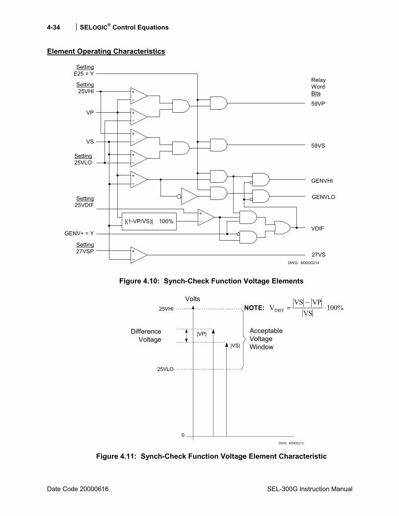
4-34 SELOGIC® Control Equations
Date Code 20000616 SEL-300G Instruction Manual
Element Operating Characteristics
+_
+_
+_
+_
+_
SettingE25 = Y
Setting25VHI
VP
VS
Setting25VLO
59VP
59VS
GENVHI
GENVLO
RelayWordBits
|(1-VP/VS)| ⋅ 100%+_
Setting25VDIF
GENV+ = YVDIF
+_
Setting27VSP 27VS
DWG: M300G214
Figure 4.10: Synch-Check Function Voltage Elements
DifferenceVoltage
|VP|
|VS|
AcceptableVoltageWindow
25VLO
25VHI
DWG: M300G213
0
Volts
Figure 4.11: Synch-Check Function Voltage Element Characteristic
NOTE: %100VS
VPVSVDIFF ⋅
−=
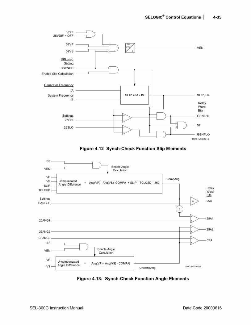
SELOGIC® Control Equations 4-35
SEL-300G Instruction Manual Date Code 20000616
fA
fS
59VS
59VP
BSYNCH
3.0CYC
0
SLIP = fA - fS
Enable Slip Calculation
SLIP, Hz
+_
GENFHI
GENFLO
25SHI
+_
25SLOSF
VEN
VDIF25VDIF = OFF
SELOGICSetting
Generator Frequency
System Frequency
Settings
RelayWordBits
DWG: M300G215
Figure 4.12 Synch-Check Function Slip Elements
CompAng
CANGLE
SF
VEN
25ANG2
SLIPVSVP
Enable AngleCalculation
TCLOSD
+
_
+
_
=
25ANG1
25C
RelayWordBits
25A2
25A1
|UncompAng|VS
VP
CFANGLCFA
+
_
SF
VEN Enable AngleCalculation
| : |
Settings
CompensatedAngle Difference
|Ang(VP) - Ang(VS) - COMPA|=UncompensatedAngle Difference
Ang(VP) - Ang(VS) -COMPA + SLIP ⋅ TCLOSD ⋅ 360=
DWG: M300G216
Figure 4.13: Synch-Check Function Angle Elements
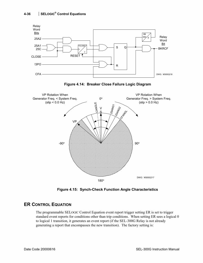
4-36 SELOGIC® Control Equations
Date Code 20000616 SEL-300G Instruction Manual
RelayWordBits
25C
CLOSE
!3PO
CFA
S
R
Q BKRCF
25A2
25A1
99sec 0
RESET
TCLOSD
0
DWG: M300G218
RelayWord
Bit
Figure 4.14: Breaker Close Failure Logic Diagram
VSC
ANG
LE0o
-90o 90o
180o
25AN
G1
25AN
G2
CFAN
GLVP
VP Rotation WhenGenerator Freq. < System Freq.
(slip < 0.0 Hz)
DWG: M300G217
VP Rotation WhenGenerator Freq. > System Freq.
(slip > 0.0 Hz)
Figure 4.15: Synch-Check Function Angle Characteristics
ER CONTROL EQUATION The programmable SELOGIC Control Equation event report trigger setting ER is set to trigger standard event reports for conditions other than trip conditions. When setting ER sees a logical 0 to logical 1 transition, it generates an event report (if the SEL-300G Relay is not already generating a report that encompasses the new transition). The factory setting is:

SELOGIC® Control Equations 4-37
SEL-300G Instruction Manual Date Code 20000616
ER = /24C2 + /32P1 + /46Q2 + /51N + /51C + /51V + /64G1 + /64G2
+ /60LOP + /81D1 + /81D2 + \81D1 + \81D2 + /BNDA + /BNDT + /INAD
Note the rising edge operator, /, in front of each of these elements. Rising edge operators are especially useful in generating an event report at fault inception and then generating another later if a breaker failure condition occurs. For example, at the inception of a stator ground fault, pickup indicator 64G1 asserts and an event report is generated:
ER = ... + /64G1 + ... = logical 1 (for one processing interval)
Even though the 64G1 pickup indicator will remain asserted for the duration of the ground fault, the rising edge operator, /, in front of 64G1 (/64G1) causes setting ER to be asserted for only one processing interval.
Falling edge operators, \, are also used to generate event reports.
OUTPUT CONTACT CONTROL Figure 4.16 and Figure 4.17 show the example operation of output contact Relay Word bits due to:
SELOGIC Control Equation operation
or
PULSE command execution
The output contact Relay Word bits in turn control the output contacts.
Alarm logic/circuitry controls the ALARM output contact.
Figure 4.16 is used for the following discussion/examples. The output contacts in Figure 4.16 and Figure 4.17 operate similarly.
Factory Settings Example
In the factory SELOGIC Control Equation settings, seven output contacts are used:
OUT101 = TRIP1 Generator Main Circuit Breaker Trip OUT102 = TRIP2 Generator Field Circuit Breaker Trip OUT103 = TRIP3 Prime Mover Trip OUT104 = TRIP4 Generator Lockout Relay Trip OUT105 = CLOSE Generator Main Breaker Close OUT106 = 60LOP Loss-of-Potential Annunciation OUT107 = 24D1T + 46Q1T + Operation alarm contact
BCW + BNDT + !(DCLO * DCHI)

4-38 SELOGIC® Control Equations
Date Code 20000616 SEL-300G Instruction Manual
Operation of Output Contacts for Different Output Contact Types
Output Contacts OUT101 Through OUT107 (All Models) and OUT201 Through OUT212
Refer to Figure 4.16 and Figure 4.17.
The execution of the serial port command PULSE n (n = OUT101 through OUT212) asserts the corresponding Relay Word bit (OUT101 through OUT212) to logical 1. The assertion of SELOGIC Control Equation setting OUTm (m = 101 through 212) to logical 1 also asserts the corresponding Relay Word bit OUTm (m = 101 through 212) to logical 1.
The assertion of Relay Word bit OUTm (m = 101 through 212) to logical 1 causes the energization of the corresponding output contact OUTm coil. Depending on the contact type (a or b), the output contact closes or opens as demonstrated in Figure 4.16. An a type output contact is open when the output contact coil is deenergized and closed when the output contact coil is energized. A b type output contact is closed when the output contact coil is deenergized and open when the output contact coil is energized.
Notice in Figure 4.16 that all four possible combinations of output contact coil states (energized or deenergized) and output contact types (a or b) are demonstrated. See Output Contact Jumpers in Section 5: Installation for output contact type options.
Output contact pickup/dropout time is 4 ms.
ALARM Output Contact
Refer to Figure 4.16 and Relay Self-Test Alarms in this section.
When the relay is operational, the ALARM output contact coil is energized. The alarm logic/circuitry keeps the ALARM output contact coil energized. Depending on the ALARM output contact type (a or b), the ALARM output contact closes or opens as demonstrated in Figure 4.16. An a type output contact is open when the output contact coil is deenergized and closed when the output contact coil is energized. A b type output contact is closed when the output contact coil is deenergized and open when the output contact coil is energized.
To verify ALARM output contact mechanical integrity, execute the serial port command PULSE ALARM. Execution of this command momentarily deenergizes the ALARM output contact coil.
The Relay Word bit ALARM is deasserted to logical 0 when the relay is operational. When the serial port command PULSE ALARM is executed, the ALARM Relay Word bit momentarily asserts to logical 1. Also, when the relay enters Access Level 2, the ALARM Relay Word bit momentarily asserts to logical 1 (and the ALARM output contact coil is deenergized momentarily).
Notice in Figure 4.16 that all possible combinations of ALARM output contact coil states (energized or deenergized) and output contact types (a or b) are demonstrated. See Output Contact Jumpers in Section 5: Installation for output contact type options.
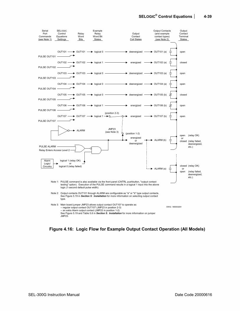
SELOGIC® Control Equations 4-39
SEL-300G Instruction Manual Date Code 20000616
Note 1: PULSE command is also available via the front panel (CNTRL pushbutton, "output contacttesting" option). Execution of the PULSE command results in a logical 1 input into the abovelogic (1-second default pulse width).
Note 2: Output contacts OUT101 through ALARM are configurable as "a" or "b" type output contacts.See Figure 5.19 in Section 5: Installation for more information on selecting output contacttype.
Note 3: Main board jumper JMP23 allows output contact OUT107 to operate as:-- regular output contact OUT107 (JMP23 in position 2-3)-- an extra Alarm output contact (JMP23 in position 1-2)See Figure 5.19 and Table 5.6 in Section 5: Installation for more information on jumperJMP23.
DWG: M300G081
SerialPort
Commands(see Note 1)
SELOGICControl
EquationsSettings
RelayWordBits
ExampleRelay
Word BitStates
OutputContact
Coil States
Output Contacts(and examplecontact types)(see Note 2)
OutputContactTerminalStates
PULSE OUT101
OUT101 OUT101 logical 0 deenergized OUT101 (a) open
PULSE OUT102
OUT102 OUT102 logical 1 energized OUT102 (a) closed
PULSE OUT103
OUT103 OUT103 logical 0 deenergized OUT103 (a) open
PULSE OUT104
OUT104 OUT104 logical 0 deenergized OUT104 (a) open
PULSE OUT105
OUT105 OUT105 logical 0 deenergized OUT105 (b) closed
PULSE OUT106
OUT106 OUT106 logical 1 energized OUT106 (b) open
PULSE OUT107
OUT107 OUT107 logical 1 energized OUT107 (b) open(position 2-3)
JMP23(see Note 3) (position 1-2)
ALARM
energizedor
deenergizedALARM (b)
ALARM (a)
open orclosed
closed oropen
(relay OK)
(relay failed,deenergized,etc.)
(relay OK)
(relay failed,deenergized,etc.)
PULSE ALARM
logical 1 (relay OK)or
logical 0 (relay failed)
AlarmLogic/
Circuitry
Relay Enters Access Level 2
Figure 4.16: Logic Flow for Example Output Contact Operation (All Models)
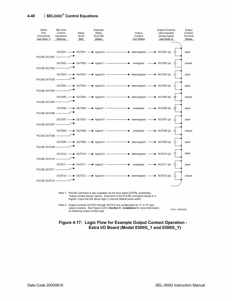
4-40 SELOGIC® Control Equations
Date Code 20000616 SEL-300G Instruction Manual
Note 1: PULSE command is also available via the front panel (CNTRL pushbutton,"output contact tesing" option). Execution of the PULSE command results in alogical 1 input into the above logic (1-second default pulse width).
Note 2: Output contacts OUT201 through OUT212 are configurable as "a" or "b" typeoutput contacts. See Figure 5.20 in Section 5: Installation for more informationon selecting output contact type. DWG: M300G082
SerialPort
Commands(see Note 1)
SELOGICControl
EquationsSettings
RelayWordBits
ExampleRelay
Word BitStates
OutputContact
Coil States
Output Contacts(and examplecontact types)(see Note 2)
OutputContactTerminalStates
PULSE OUT201
OUT201 OUT201 logical 0 deenergized OUT201 (a) open
PULSE OUT202
OUT202 OUT202 logical 1 energized OUT202 (a) closed
PULSE OUT203
OUT203 OUT203 logical 0 deenergized OUT203 (a) open
PULSE OUT204
OUT204 OUT204 logical 0 deenergized OUT204 (a) open
PULSE OUT205
OUT205 OUT205 logical 0 deenergized OUT205 (b) closed
PULSE OUT206
OUT206 OUT206 logical 1 energized OUT206 (b) open
PULSE OUT207
OUT207 OUT207 logical 0 deenergized OUT207 (a) open
OUT208 (a)
OUT209 (a)
OUT210 (a)
OUT211 (b)
OUT212 (b)
energized
deenergized
deenergized
energized
deenergized
OUT208 logical 1
OUT209 logical 0
OUT210 logical 0
OUT211 logical 1
OUT212 logical 0
PULSE OUT208
OUT208
PULSE OUT209
OUT209
PULSE OUT210
OUT210
PULSE OUT211
OUT211
PULSE OUT212
OUT212
closed
open
open
open
closed
Figure 4.17: Logic Flow for Example Output Contact Operation - Extra I/O Board (Model 0300G_1 and 0300G_Y)
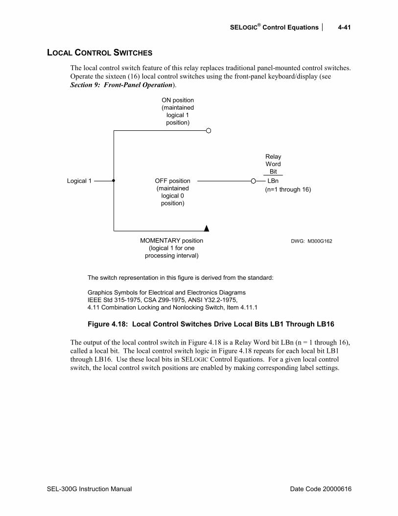
SELOGIC® Control Equations 4-41
SEL-300G Instruction Manual Date Code 20000616
LOCAL CONTROL SWITCHES The local control switch feature of this relay replaces traditional panel-mounted control switches. Operate the sixteen (16) local control switches using the front-panel keyboard/display (see Section 9: Front-Panel Operation).
OFF position(maintained
logical 0position)
MOMENTARY position(logical 1 for one
processing interval)
DWG: M300G162
RelayWord
BitLBnLogical 1
(n=1 through 16)
ON position(maintained
logical 1position)
The switch representation in this figure is derived from the standard:
Graphics Symbols for Electrical and Electronics DiagramsIEEE Std 315-1975, CSA Z99-1975, ANSI Y32.2-1975,4.11 Combination Locking and Nonlocking Switch, Item 4.11.1
Figure 4.18: Local Control Switches Drive Local Bits LB1 Through LB16
The output of the local control switch in Figure 4.18 is a Relay Word bit LBn (n = 1 through 16), called a local bit. The local control switch logic in Figure 4.18 repeats for each local bit LB1 through LB16. Use these local bits in SELOGIC Control Equations. For a given local control switch, the local control switch positions are enabled by making corresponding label settings.
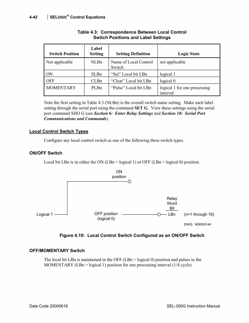
4-42 SELOGIC® Control Equations
Date Code 20000616 SEL-300G Instruction Manual
Table 4.3: Correspondence Between Local Control Switch Positions and Label Settings
Switch Position
Label Setting
Setting Definition
Logic State
Not applicable NLBn Name of Local Control Switch
not applicable
ON SLBn Set Local bit LBn logical 1 OFF CLBn Clear Local bit LBn logical 0 MOMENTARY PLBn Pulse Local bit LBn logical 1 for one processing
interval
Note the first setting in Table 4.3 (NLBn) is the overall switch name setting. Make each label setting through the serial port using the command SET G. View these settings using the serial port command SHO G (see Section 6: Enter Relay Settings and Section 10: Serial Port Communications and Commands).
Local Control Switch Types
Configure any local control switch as one of the following three switch types.
ON/OFF Switch
Local bit LBn is in either the ON (LBn = logical 1) or OFF (LBn = logical 0) position.
OFF position(logical 0)
ONposition
DWG: M300G144
RelayWord
BitLBnLogical 1 (n=1 through 16)
Figure 4.19: Local Control Switch Configured as an ON/OFF Switch
OFF/MOMENTARY Switch
The local bit LBn is maintained in the OFF (LBn = logical 0) position and pulses to the MOMENTARY (LBn = logical 1) position for one processing interval (1/4 cycle).

SELOGIC® Control Equations 4-43
SEL-300G Instruction Manual Date Code 20000616
OFF position(logical 0)
MOMENTARYposition DWG: M300G143
RelayWord
BitLBnLogical 1 (n=1 through 16)
Figure 4.20: Local Control Switch Configured as an OFF/MOMENTARY Switch
ON/OFF/MOMENTARY Switch
The local bit LBn:
is in either the ON (LBn = logical 1) or OFF (LBn = logical 0) position
or
is in the OFF (LBn = logical 0) position and pulses to the MOMENTARY (LBn = logical 1) position for one processing interval (1/4 cycle).
OFF position(logical 0)
MOMENTARYposition DWG: M300G145
RelayWord
BitLBnLogical 1 (n=1 through 16)
ONposition
Figure 4.21: Local Control Switch Configured as an ON/OFF/MOMENTARY Switch
Table 4.4: Correspondence Between Local Control Switch Types and Required Label Settings
Local Switch Type Label NLBn Label CLBn Label SLBn Label PLBn
ON/OFF X X X OFF/MOMENTARY X X X ON/OFF/MOMENTARY X X X X

4-44 SELOGIC® Control Equations
Date Code 20000616 SEL-300G Instruction Manual
Disable local control switches by nulling out all the label settings for that switch (see Section 6: Enter Relay Settings). The local bit associated with this disabled local control switch then is fixed at logical 0.
Factory Settings Examples
Local bit LB1 is used in a few of the factory SELOGIC Control Equation settings for manual generator shutdown. Its corresponding local control switch position labels are set to configure the switches as OFF/MOMENTARY switches:
Local Bit Label Settings Function
LB1 NLB1 = GEN SHUTDOWN
trips prime mover and initiates generator main circuit breaker and field circuit breaker sequential trips
CLB1 = RETURN OFF position (return from MOMENTARY position)
SLB1 = ON position not used (left blank) PLB1 = TRIP MOMENTARY position
The following Figure 4.22 shows local control switches with factory settings.
RETURN(logical 0)
TRIP
GEN SHUTDOWN
DWG: M300G080
LocalBit
LB1Logical 1
Figure 4.22: Configured GEN SHUTDOWN Switch Drives Local Bit LB1
Local bit LB2 is not included in the factory settings, but could be applied as a local generator breaker close function using the settings shown below.
Local Bit Label Settings Function
LB2 NLB2 = GEN BKR CLOSE initiates generator main circuit breaker close. Sequence completes only if CLEN SELOGIC Control Equation result is a logical 1 within CLSD seconds of sequence initiation.
CLB2 = RETURN OFF position (return from MOMENTARY position)
SLB2 = ON position not used (left blank) PLB2 = CLOSE MOMENTARY position

SELOGIC® Control Equations 4-45
SEL-300G Instruction Manual Date Code 20000616
Local bit LB1 is used along with remote bit RB1 to set latch bit LT1 which then trips the prime mover.
Additional Local Control Switch Application Ideas
The preceding factory settings example uses an OFF/MOMENTARY switch. Local control switches configured as ON/OFF switches can be used for such applications as protection element enable/disable.
Local control switches also can be configured as ON/OFF/MOMENTARY switches for applications that require them. Local control switches can be applied to almost any control scheme that traditionally requires front-panel switches.
Local Control Switch States Retained
Power Loss
The states of the local bits (Relay Word bits LB1 through LB16) are retained if power to the relay is lost and then restored. If a local control switch is in the ON position (corresponding local bit is asserted to logical 1) when power is lost, it comes back in the ON position (corresponding local bit is still asserted to logical 1) when power is restored. If a local control switch is in the OFF position (corresponding local bit is deasserted to logical 0) when power is lost, it comes back in the OFF position (corresponding local bit is still deasserted to logical 0) when power is restored. This feature makes the local bit feature behave the same as a traditional installation with panel-mounted control switches. If power is lost to the panel, the front-panel control switch positions remain unchanged.
Settings Change or Active Setting Group Change
If settings are changed (for the active setting group or the other setting group) or the active setting group is changed, the states of the local bits (Relay Word bits LB1 through LB16) are retained, much like in the preceding Power Loss explanation.
If a local control switch is made inoperable because of a settings change (i.e., the corresponding label settings are nulled), the corresponding local bit then is fixed at logical 0, regardless of the local bit state before the settings change. If a local control switch is made newly operable because of a settings change (i.e., the corresponding label settings are set), the corresponding local bit starts out at logical 0.
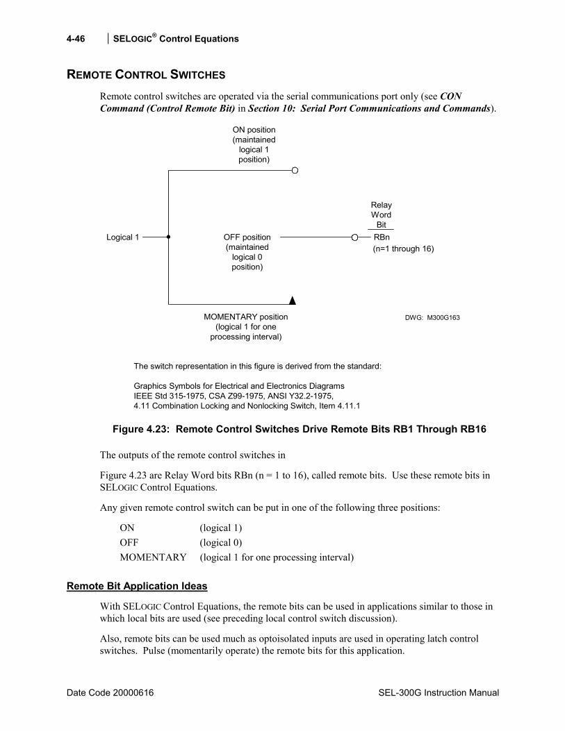
4-46 SELOGIC® Control Equations
Date Code 20000616 SEL-300G Instruction Manual
REMOTE CONTROL SWITCHES Remote control switches are operated via the serial communications port only (see CON Command (Control Remote Bit) in Section 10: Serial Port Communications and Commands).
OFF position(maintained
logical 0position)
MOMENTARY position(logical 1 for one
processing interval)
DWG: M300G163
RelayWord
BitRBnLogical 1(n=1 through 16)
ON position(maintained
logical 1position)
The switch representation in this figure is derived from the standard:
Graphics Symbols for Electrical and Electronics DiagramsIEEE Std 315-1975, CSA Z99-1975, ANSI Y32.2-1975,4.11 Combination Locking and Nonlocking Switch, Item 4.11.1
Figure 4.23: Remote Control Switches Drive Remote Bits RB1 Through RB16
The outputs of the remote control switches in
Figure 4.23 are Relay Word bits RBn (n = 1 to 16), called remote bits. Use these remote bits in SELOGIC Control Equations.
Any given remote control switch can be put in one of the following three positions:
ON (logical 1) OFF (logical 0) MOMENTARY (logical 1 for one processing interval)
Remote Bit Application Ideas
With SELOGIC Control Equations, the remote bits can be used in applications similar to those in which local bits are used (see preceding local control switch discussion).
Also, remote bits can be used much as optoisolated inputs are used in operating latch control switches. Pulse (momentarily operate) the remote bits for this application.

SELOGIC® Control Equations 4-47
SEL-300G Instruction Manual Date Code 20000616
Remote Bit States Not Retained When Power is Lost
The states of the remote bits (Relay Word bits RB1 through RB16) are not retained if power to the relay is lost and then restored. The remote control switches always come back in the OFF position (corresponding remote bit is deasserted to logical 0) when power is restored to the relay.
Remote Bit States Retained When Settings Changed or Active Setting Group Changed
The state of each remote bit (Relay Word bits RB1 through RB16) is retained if relay settings are changed (for the active setting group or the other setting group) or the active setting group is changed. If a remote control switch is in the ON position (corresponding remote bit is asserted to logical 1) before a setting change or an active setting group change, it comes back in the ON position (corresponding remote bit is still asserted to logical 1) after the change. If a remote control switch is in the OFF position (corresponding remote bit is deasserted to logical 0) before a settings change or an active setting group change, it comes back in the OFF position (corresponding remote bit is still deasserted to logical 0) after the change.
FRONT-PANEL DISPLAY CONFIGURATION The rotating default display on the relay front panel replaces indicating panel meters and lights. Traditional panel meters indicate generator electrical quantities such as:
phase current phase voltage generator output power generator frequency
Traditional indicating panel lights are turned on and off by circuit breaker auxiliary contacts, front-panel switches, SCADA contacts, etc. They indicate such conditions as:
circuit breaker open/closed protection elements enabled/disabled
Traditional Indicating Panel Meters
Traditional indicating panel meters are wired to ac current and voltage transformers in series or parallel with SEL-300G Relay ac inputs. The panel meters then measure and display desired quantities, such as current magnitude, voltage magnitude, generator frequency, generator output power, etc.
Traditional Indicating Panel Meters Replaced with Rotating Meter Display
The indicating panel meters are not needed if the rotating default display feature in the SEL-300G Relay is applied. The relay already is measuring the desired quantities to a high degree of accuracy. Simply configure the front-panel display settings to enable the automatic display of real-time measured quantities.
To enable real-time display of measured quantities, use the serial port SET G command or front-panel SET GLOBAL setting entry functions (see Section 6: Enter Relay Settings and
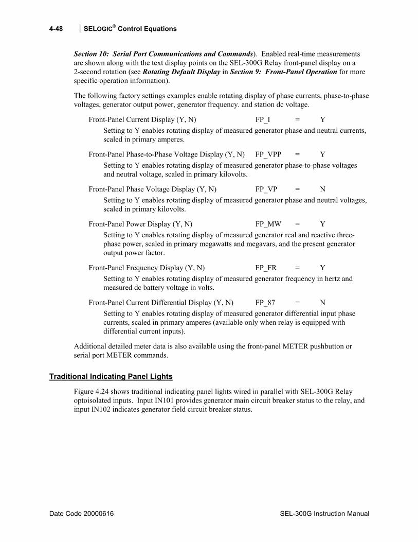
4-48 SELOGIC® Control Equations
Date Code 20000616 SEL-300G Instruction Manual
Section 10: Serial Port Communications and Commands). Enabled real-time measurements are shown along with the text display points on the SEL-300G Relay front-panel display on a 2-second rotation (see Rotating Default Display in Section 9: Front-Panel Operation for more specific operation information).
The following factory settings examples enable rotating display of phase currents, phase-to-phase voltages, generator output power, generator frequency. and station dc voltage.
Front-Panel Current Display (Y, N) FP_I = Y Setting to Y enables rotating display of measured generator phase and neutral currents, scaled in primary amperes.
Front-Panel Phase-to-Phase Voltage Display (Y, N) FP_VPP = Y Setting to Y enables rotating display of measured generator phase-to-phase voltages and neutral voltage, scaled in primary kilovolts.
Front-Panel Phase Voltage Display (Y, N) FP_VP = N Setting to Y enables rotating display of measured generator phase and neutral voltages, scaled in primary kilovolts.
Front-Panel Power Display (Y, N) FP_MW = Y Setting to Y enables rotating display of measured generator real and reactive three-phase power, scaled in primary megawatts and megavars, and the present generator output power factor.
Front-Panel Frequency Display (Y, N) FP_FR = Y Setting to Y enables rotating display of measured generator frequency in hertz and measured dc battery voltage in volts.
Front-Panel Current Differential Display (Y, N) FP_87 = N Setting to Y enables rotating display of measured generator differential input phase currents, scaled in primary amperes (available only when relay is equipped with differential current inputs).
Additional detailed meter data is also available using the front-panel METER pushbutton or serial port METER commands.
Traditional Indicating Panel Lights
Figure 4.24 shows traditional indicating panel lights wired in parallel with SEL-300G Relay optoisolated inputs. Input IN101 provides generator main circuit breaker status to the relay, and input IN102 indicates generator field circuit breaker status.
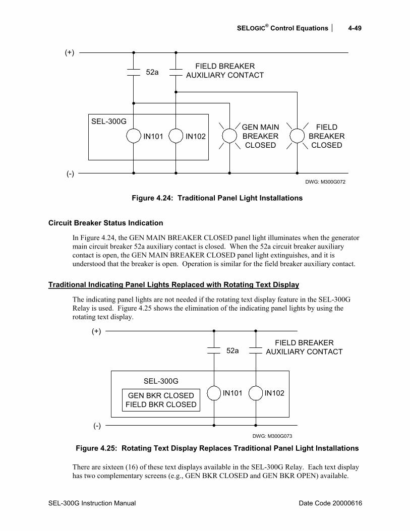
SELOGIC® Control Equations 4-49
SEL-300G Instruction Manual Date Code 20000616
DWG: M300G072
FIELD BREAKERAUXILIARY CONTACT52a
SEL-300G
(+)
IN102GEN MAINBREAKERCLOSED
FIELDBREAKERCLOSED
(-)
IN101
Figure 4.24: Traditional Panel Light Installations
Circuit Breaker Status Indication
In Figure 4.24, the GEN MAIN BREAKER CLOSED panel light illuminates when the generator main circuit breaker 52a auxiliary contact is closed. When the 52a circuit breaker auxiliary contact is open, the GEN MAIN BREAKER CLOSED panel light extinguishes, and it is understood that the breaker is open. Operation is similar for the field breaker auxiliary contact.
Traditional Indicating Panel Lights Replaced with Rotating Text Display
The indicating panel lights are not needed if the rotating text display feature in the SEL-300G Relay is used. Figure 4.25 shows the elimination of the indicating panel lights by using the rotating text display.
DWG: M300G073
FIELD BREAKERAUXILIARY CONTACT52a
SEL-300G
(+)
IN102
(-)
IN101GEN BKR CLOSEDFIELD BKR CLOSED
Figure 4.25: Rotating Text Display Replaces Traditional Panel Light Installations
There are sixteen (16) of these text displays available in the SEL-300G Relay. Each text display has two complementary screens (e.g., GEN BKR CLOSED and GEN BKR OPEN) available.
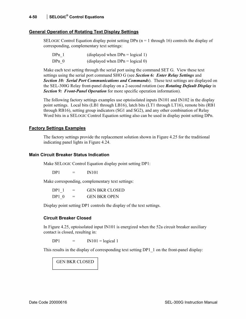
4-50 SELOGIC® Control Equations
Date Code 20000616 SEL-300G Instruction Manual
General Operation of Rotating Text Display Settings
SELOGIC Control Equation display point setting DPn (n = 1 through 16) controls the display of corresponding, complementary text settings:
DPn_1 (displayed when DPn = logical 1) DPn_0 (displayed when DPn = logical 0)
Make each text setting through the serial port using the command SET G. View these text settings using the serial port command SHO G (see Section 6: Enter Relay Settings and Section 10: Serial Port Communications and Commands). These text settings are displayed on the SEL-300G Relay front-panel display on a 2-second rotation (see Rotating Default Display in Section 9: Front-Panel Operation for more specific operation information).
The following factory settings examples use optoisolated inputs IN101 and IN102 in the display point settings. Local bits (LB1 through LB16), latch bits (LT1 through LT16), remote bits (RB1 through RB16), setting group indicators (SG1 and SG2), and any other combination of Relay Word bits in a SELOGIC Control Equation setting also can be used in display point setting DPn.
Factory Settings Examples
The factory settings provide the replacement solution shown in Figure 4.25 for the traditional indicating panel lights in Figure 4.24.
Main Circuit Breaker Status Indication
Make SELOGIC Control Equation display point setting DP1:
DP1 = IN101
Make corresponding, complementary text settings:
DP1_1 = GEN BKR CLOSED DP1_0 = GEN BKR OPEN
Display point setting DP1 controls the display of the text settings.
Circuit Breaker Closed
In Figure 4.25, optoisolated input IN101 is energized when the 52a circuit breaker auxiliary contact is closed, resulting in:
DP1 = IN101 = logical 1
This results in the display of corresponding text setting DP1_1 on the front-panel display:
GEN BKR CLOSED
SELOGIC® Control Equations 4-51
SEL-300G Instruction Manual Date Code 20000616
Circuit Breaker Open
In Figure 4.25, optoisolated input IN101 is deenergized when the 52a circuit breaker auxiliary contact is open, resulting in:
DP1 = IN101 = logical 0
This results in the display of corresponding text setting DP1_0 on the front-panel display:
GEN BKR OPEN
Additional Settings Examples
Display Only One Message
To display just one screen, but not its complement, set only one of the text settings. For example, to display just the breaker closed condition but not the breaker open condition, make the following settings:
DP1 = IN101 (52a circuit breaker auxiliary contact connected to input IN101 see Figure 4.25)
DP1_1 = GEN BKR CLOSED (displays when DP1 = logical 1)
DP1_0 = (blank)
Circuit Breaker Closed
In Figure 4.25, optoisolated input IN101 is energized when the 52a circuit breaker auxiliary contact is closed, resulting in:
DP1 = IN101 = logical 1
This results in the display of corresponding text setting DP1_1 on the front-panel display:
GEN BKR CLOSED
Circuit Breaker Open
In Figure 4.25, optoisolated input IN101 is deenergized when the 52a circuit breaker auxiliary contact is open, resulting in:
DP1 = IN101 = logical 0
Corresponding text setting DP1_0 is not set (it is blank), so no message is displayed on the front-panel display.

4-52 SELOGIC® Control Equations
Date Code 20000616 SEL-300G Instruction Manual
Continually Display a Message
To continually display a message in the rotation, set the SELOGIC Control Equation display point setting directly to 0 (logical 0) or 1 (logical 1) and the corresponding text setting. For example, if an SEL-300G Relay is protecting a generator labeled Unit 1A, the generator name can be continually displayed with the following settings
DP5 = 1 (set directly to logical 1)
DP5_1 = UNIT 1A (displays when DP5 = logical 1)
DP5_0 = (blank)
This results in the continual display of text setting DP5_1 on the front-panel display:
UNIT 1A
This also can be realized with the following settings:
DP5 = 0 (set directly to logical 0)
DP5_1 = (blank)
DP5_0 = UNIT 1A (displays when DP5 = logical 0)
This results in the continual display of text setting DP5_0 on the front-panel display:
UNIT 1A
INADVERTENT ENERGIZATION Inadvertent energization occurs when the generator main circuit breaker or auxiliary transformer circuit breaker is incorrectly closed to energize the generator while the generator is out of service. When this occurs, the generator can act as an induction motor, drawing as much as four to six times rated stator current from the system. These high stator currents induce high currents in the rotor, quickly damaging the rotor.
The SEL-300G Relay INAD SELOGIC Control Equation is intended for use as dedicated inadvertent energization protection. Two accepted approaches are voltage supervised overcurrent relays and auxiliary contact supervised overcurrent relays. The INAD SELOGIC Control Equation supports both.
The objective of inadvertent energization protection is to detect that the generator has been removed from service, but has suddenly been reenergized. We can begin to build the INAD equation:
INAD = [Generator was deenergized] * [Generator is now energized]
If we use an overcurrent element, 50L, to detect that the generator has been reenergized, then the INAD equation can be described:
SELOGIC® Control Equations 4-53
SEL-300G Instruction Manual Date Code 20000616
INAD = [Generator was deenergized] * 50L
It now remains to define the [Generator was deenergized] conditions.
Some indicators that the generator is removed from service include:
• Low terminal voltage • Field circuit breaker is open • No phase current
We can require that all these conditions be true to arm Inadvertent Energization tripping by using the SELOGIC Control Equation AND operator:
Generator is deenergized = !50L * 27V1 * !IN102
where !50L = 50L sensitive phase overcurrent element is not picked up 27V1 = positive-sequence phase undervoltage element is picked up !IN102 = field circuit breaker auxiliary contact is open
We need to add time-delay pickup and dropout timers to this logic equation. The time-delay pickup timer adds an arming delay so that the inadvertent energization scheme is not armed until a few seconds after the generator is removed from service. The dropout timer ensures that the scheme will trip when current is applied during an inadvertent energization. A SELOGIC Control Equation is used to provide the arming delays:
SV2 = !50L * 27V1 * !IN102 SV2PU = 2.0 seconds SV2DO = 1.0 second
With these settings, the INAD settings become:
INAD = SV2T * 50L Generator was deenergized and current is now detected
INADPU = 0.25 second 1/4-second time delay on inadvertent energization trip INADDO = 0.13 second One-eighth second time delay on INAD trip dropout
The INADT Relay Word bit is added to the SV3 SELOGIC Control Equation to trip the generator main circuit breaker, the field breaker, the prime mover, and the generator lockout relay when an inadvertent energization occurs. The logic diagram in Figure 4.26 summarizes the logic.
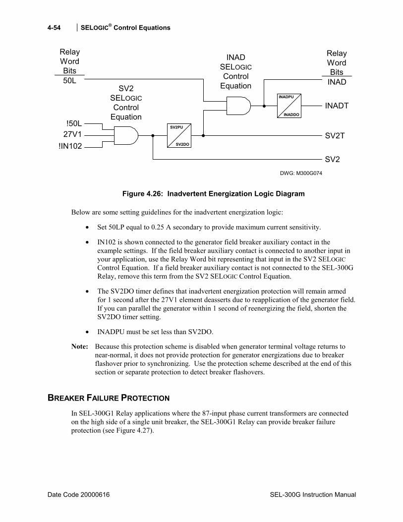
4-54 SELOGIC® Control Equations
Date Code 20000616 SEL-300G Instruction Manual
INADPU
INADDO
INADT
INADSELOGICControl
Equation
SV2TSV2PU
SV2DO
SV2
SV2SELOGICControl
Equation!50L
27V1!IN102
DWG: M300G074
RelayWordBits50L
RelayWordBits
INAD
Figure 4.26: Inadvertent Energization Logic Diagram
Below are some setting guidelines for the inadvertent energization logic:
• Set 50LP equal to 0.25 A secondary to provide maximum current sensitivity.
• IN102 is shown connected to the generator field breaker auxiliary contact in the example settings. If the field breaker auxiliary contact is connected to another input in your application, use the Relay Word bit representing that input in the SV2 SELOGIC Control Equation. If a field breaker auxiliary contact is not connected to the SEL-300G Relay, remove this term from the SV2 SELOGIC Control Equation.
• The SV2DO timer defines that inadvertent energization protection will remain armed for 1 second after the 27V1 element deasserts due to reapplication of the generator field. If you can parallel the generator within 1 second of reenergizing the field, shorten the SV2DO timer setting.
• INADPU must be set less than SV2DO.
Note: Because this protection scheme is disabled when generator terminal voltage returns to near-normal, it does not provide protection for generator energizations due to breaker flashover prior to synchronizing. Use the protection scheme described at the end of this section or separate protection to detect breaker flashovers.
BREAKER FAILURE PROTECTION In SEL-300G1 Relay applications where the 87-input phase current transformers are connected on the high side of a single unit breaker, the SEL-300G1 Relay can provide breaker failure protection (see Figure 4.27).

SELOGIC® Control Equations 4-55
SEL-300G Instruction Manual Date Code 20000616
DWG: M300G077
SEL-300G1(Partial)
GEN
52
87 Inputs
33
OptionalStep-up
Transformer
Figure 4.27: Generator/Breaker Topology Where SEL-300G1 Relay Offers Breaker Failure Protection
In this topology, the SEL-300G Relay is able to directly measure current flowing in the generator breaker. The SV7 SELOGIC Control Equation below creates a breaker failure function based on circuit breaker current and the breaker auxiliary contact, 52A, state. The SELOGIC Control Equation logic is shown in Figure 4.28.
SV7 = (SV7 + IN103 + TRIP1) * (50H1 + 50R1 + 52A)
SV7PU
SV7DO
SV7
SV7TIN103
TRIP1
50H1
50R152A DWG: M300G075
RelayWordBitsRelay
WordBits
Figure 4.28: SEL-300G Relay Breaker Failure Logic
Breaker failure time is defined by the SV7PU time-delay pickup timer setting. This timer starts when the SEL-300G Relay TRIP1 Relay Word bit asserts, or when external protection asserts the IN103 input if the breaker is closed (52A = logical 1), or if the 87-input phase or residual overcurrent element is picked up (50H1 or 50R1 = logical 1). By including the SV7 Relay Word bit in the SV7 SELOGIC Control Equation, the breaker failure initiate condition is latched in. The SV7PU timer continues to run until the breaker opens (52A = logical 0) and the measured current drops below the pickup setting of both overcurrent elements. Assign the SV7T Relay Word bit to close an output contact which then can be connected to perform breaker failure lockout tripping.
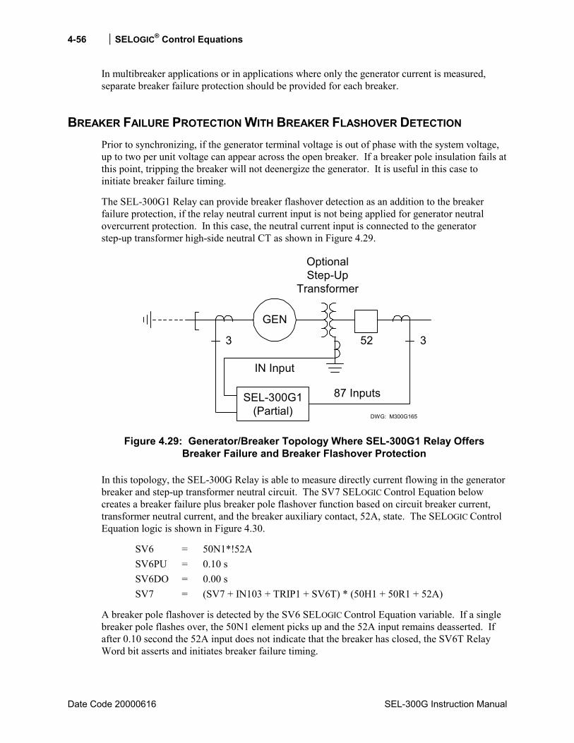
4-56 SELOGIC® Control Equations
Date Code 20000616 SEL-300G Instruction Manual
In multibreaker applications or in applications where only the generator current is measured, separate breaker failure protection should be provided for each breaker.
BREAKER FAILURE PROTECTION WITH BREAKER FLASHOVER DETECTION Prior to synchronizing, if the generator terminal voltage is out of phase with the system voltage, up to two per unit voltage can appear across the open breaker. If a breaker pole insulation fails at this point, tripping the breaker will not deenergize the generator. It is useful in this case to initiate breaker failure timing.
The SEL-300G1 Relay can provide breaker flashover detection as an addition to the breaker failure protection, if the relay neutral current input is not being applied for generator neutral overcurrent protection. In this case, the neutral current input is connected to the generator step-up transformer high-side neutral CT as shown in Figure 4.29.
DWG: M300G165
SEL-300G1(Partial)
GEN
52
87 Inputs
33
OptionalStep-Up
Transformer
IN Input
Figure 4.29: Generator/Breaker Topology Where SEL-300G1 Relay Offers Breaker Failure and Breaker Flashover Protection
In this topology, the SEL-300G Relay is able to measure directly current flowing in the generator breaker and step-up transformer neutral circuit. The SV7 SELOGIC Control Equation below creates a breaker failure plus breaker pole flashover function based on circuit breaker current, transformer neutral current, and the breaker auxiliary contact, 52A, state. The SELOGIC Control Equation logic is shown in Figure 4.30.
SV6 = 50N1*!52A SV6PU = 0.10 s SV6DO = 0.00 s SV7 = (SV7 + IN103 + TRIP1 + SV6T) * (50H1 + 50R1 + 52A)
A breaker pole flashover is detected by the SV6 SELOGIC Control Equation variable. If a single breaker pole flashes over, the 50N1 element picks up and the 52A input remains deasserted. If after 0.10 second the 52A input does not indicate that the breaker has closed, the SV6T Relay Word bit asserts and initiates breaker failure timing.

SELOGIC® Control Equations 4-57
SEL-300G Instruction Manual Date Code 20000616
SV7PU
SV7DO
SV7
SV7T
DWG: M300G164
RelayWordBits
IN103
TRIP1
50H1
50R152A
RelayWordBits
50N152A
SV6PU
SV6DO
Figure 4.30: SEL-300G Relay Breaker Failure Plus Breaker Flashover Protection Logic
Breaker failure time is defined by the SV7PU time-delay pickup timer setting. If phase or residual current is detected, or if the 52A contact indicates the breaker is closed, the SV7PU timer starts when:
• the SEL-300G Relay TRIP1 Relay Word bit asserts, or • when external protection asserts the IN103 input, or • if transformer neutral current is detected (50N1) while the breaker is open (!52A),
indicating a breaker pole flashover.
By including the SV7 Relay Word bit in the SV7 SELOGIC Control Equation, the breaker failure initiate condition is latched in. The SV7PU timer continues to run until the breaker opens (52A = logical 0) and the measured current drops below the pickup setting of both overcurrent elements. Assign the SV7T Relay Word bit to close an output contact which can then be connected to perform breaker failure lockout tripping.
In multibreaker applications or in applications where only the generator current is measured, separate breaker failure and breaker flashover protection should be provided for each breaker.
APPLICATION EXAMPLES
Performance Alarms
Several protection elements can provide abnormal operation alarms prior to tripping the generator. In some cases, the early alarm may give an operator the opportunity to correct the problem before the relay trips the generator. In addition, the SEL-300G Relay provides several monitoring functions that can provide alarms related to loss of relaying potential, relay performance, dc battery voltage, and breaker wear. This section describes application of those alarms.

4-58 SELOGIC® Control Equations
Date Code 20000616 SEL-300G Instruction Manual
Protection Element Alarms
Volts/Hertz Overexcitation Alarms, 24D1T and 24C2
The relay provides two options for overexcitation alarms based on volts/hertz measurement. You can use the Level 1 definite-time element, 24D1T, to provide a sensitive, time-delayed indication of excessive volts/hertz. Some protection schemes call for a definite-time limit on volts/hertz overexcitation. In this instance, you may wish to use the 24D1T element for tripping. In this case, the instantaneous pickup elements, 24D1 and 24C2, can be used to indicate that the SEL-300G Relay has detected volts/hertz overexcitation and is timing toward a trip. To obtain this indication, include the desired Relay Word bit in the SELOGIC Control Equation for the indicating output contact. In our factory example, OUT107 is used:
OUT107 = + 24D1 + 24C2 +
Unbalance Current Alarm, 46Q1T and 46Q2
As with volts/hertz protection, the relay provides a definite-time and an inverse-time level of negative-sequence overcurrent protection. You may use either the definite-time element, 46Q1T, or the instantaneous pickup of the inverse-time element, 46Q2, to generate an alarm:
OUT107 = + 46Q1T +
Loss-of-Potential, 60LOP
Because accurate relaying potentials are required by many of the protection elements, the 60LOP function is used to supervise these functions. The volts/hertz element, loss-of-field element, directional power element, voltage-restrained and voltage-controlled phase overcurrent elements, and Zone 2 stator ground fault element all require accurate relaying potentials for correct operation. It is critical that a loss-of-potential is indicated so the problem may be corrected and protection returned to service.
The factory setting example uses OUT106 to indicate loss-of-potential:
OUT106 = 60LOP
Generator Off-Frequency Accumulator Protection
The Off-Frequency Operating Time Accumulator protection function, described in Section 2: Relay Element Settings, can be used to either trip or alarm when the generator exceeds the operating time limits entered as relay settings. To use the output of this function as an annunciator, add the BNDT Relay Word bit to the protection alarm annunciator contact. The factory setting example uses OUT107:
OUT107 = + BNDT +
Circuit Breaker Wear Monitor
The SEL-300G Relay circuit breaker wear monitor function described in Section 3: Auxiliary Function Settings provides an indication, BCW, when the combination of close-to-open
SELOGIC® Control Equations 4-59
SEL-300G Instruction Manual Date Code 20000616
operations and interrupted current exceeds the breaker manufacturers wear recommendation, as entered into the relay via the settings. To provide an annunciator indication that the circuit breaker wear rating has been exceeded, add the BCW Relay Word bit to the protection alarm annunciator contact SELOGIC Control Equation:
OUT107 = + BCW +
DC Voltage Monitor
Section 3: Auxiliary Function Settings offers several examples of methods to indicate that the dc voltage applied to the relay is outside normal bounds. To cause OUT107 to close while the dc voltage is out of tolerance, but still high enough that the relay is operable, add the following statement to the OUT107 SELOGIC Control Equation:
OUT107 = + !(DCLO * DCHI) +
With the setting DCHIP set below normal dc voltage and DCLOP set above normal dc voltage, OUT107 will close if the dc voltage rises above DCLOP or falls below DCHIP. If dc voltage fails altogether, the relay ALARM contact will close.
Relay Self-Test Alarms
The relay runs a variety of self-tests. As shown below, many relay problems detected by self-test cause a closure of the ALARM output contact. Monitoring this contact is the single most important relay maintenance activity that you can perform.
The relay takes the following corrective actions for out-of-tolerance conditions (see Table 4.5):
• Protection Disabled: The relay disables all protection functions and trip/close logic. All output contacts are deenergized. The EN front-panel LED is extinguished.
• ALARM Output: The ALARM output contact signals an alarm condition by going to its deenergized state. If the ALARM output contact is a b contact (normally closed), it closes for an alarm condition or if the relay is deenergized. If the ALARM output contact is an a contact (normally open), it opens for an alarm condition or if the relay is deenergized. Alarm condition signaling can be a single 5-second pulse (Pulsed) or permanent (Latched).
• The relay generates automatic STATUS reports at the serial port for warnings and failures.
• The relay displays failure messages on the relay LCD display for failures.
Use the serial port STATUS command or front-panel STATUS pushbutton to view relay self-test status.

4-60 SELOGIC® Control Equations
Date Code 20000616 SEL-300G Instruction Manual
Table 4.5: Relay Self-Tests
Self-Test
Condition
Limits
Protection Disabled
ALARM Output
Description
IA, IB, IC, IN, VA, VB, VC, VN Offset
Warning 30 mV No Pulsed Measures the dc offset at each of the input channels every 10 seconds.
Master Offset
Warning 20 mV No Pulsed Measures the dc offset at the A/D every 10 seconds.
Failure 30 mV Yes Latched
+5 V PS Warning +4.80 V +5.20 V
No Pulsed Measures the +5 V power supply every 10 seconds.
Failure +4.65 V +5.40 V
Yes Latched
+5 V REG Warning +4.75 V +5.20, -5.25 V
No Pulsed Measures the regulated 5 V power supply every 10 seconds.
Failure +4.50 V +5.40, -5.50 V
Yes Latched
+12 V PS Warning +11.50 V +12.50 V
No Pulsed Measures the 12 V power supply every 10 seconds.
Failure +11.20 V +14.00 V
Yes Latched
+15 V PS Warning +14.40 V +15.60 V
No Pulsed Measures the 15 V power supply every 10 seconds.
Failure +14.00 V +16.00 V
Yes Latched
TEMP Warning -40° C +85° C
No Measures the temperature at the A/D voltage reference every 10 seconds.
Failure -50° C +100° C
Yes Latched
RAM Failure Yes Latched Performs a read/write test on system RAM every 60 seconds.

SELOGIC® Control Equations 4-61
SEL-300G Instruction Manual Date Code 20000616
Self-Test
Condition
Limits
Protection Disabled
ALARM Output
Description
ROM Failure checksum Yes Latched Performs a checksum test on the relay program memory every 10 seconds.
A/D Failure Yes Latched Validates proper number of conversions each 1/4 cycle.
CR_RAM Failure checksum Yes Latched Performs a checksum test on the active copy of the relay settings every 10 seconds.
EEPROM Failure checksum Yes Latched Performs a checksum test on the nonvolatile copy of the relay settings every 10 seconds.
The following self-tests are performed by dedicated circuitry in the microprocessor and the SEL-300G Relay main board. Failures in these tests shut down the microprocessor and are not shown in the STATUS report.
Micro-processor Crystal
Failure Yes Latched The relay monitors the microprocessor crystal. If the crystal fails, the relay displays CLOCK STOPPED on the LCD display. The test runs continuously.
Micro-processor
Failure Yes Latched The microprocessor examines each program instruction, memory access, and interrupt. The relay displays VECTOR nn on the LCD upon detection of an invalid instruction, memory access, or spurious interrupt. The test runs continuously.
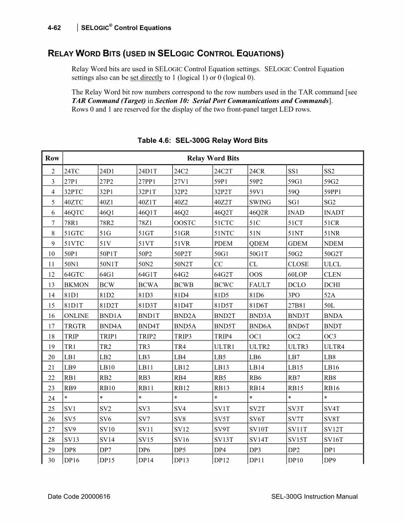
4-62 SELOGIC® Control Equations
Date Code 20000616 SEL-300G Instruction Manual
RELAY WORD BITS (USED IN SELOGIC CONTROL EQUATIONS) Relay Word bits are used in SELOGIC Control Equation settings. SELOGIC Control Equation settings also can be set directly to 1 (logical 1) or 0 (logical 0).
The Relay Word bit row numbers correspond to the row numbers used in the TAR command [see TAR Command (Target) in Section 10: Serial Port Communications and Commands]. Rows 0 and 1 are reserved for the display of the two front-panel target LED rows.
Table 4.6: SEL-300G Relay Word Bits
Row Relay Word Bits
2 24TC 24D1 24D1T 24C2 24C2T 24CR SS1 SS2 3 27P1 27P2 27PP1 27V1 59P1 59P2 59G1 59G2 4 32PTC 32P1 32P1T 32P2 32P2T 59V1 59Q 59PP1 5 40ZTC 40Z1 40Z1T 40Z2 40Z2T SWING SG1 SG2 6 46QTC 46Q1 46Q1T 46Q2 46Q2T 46Q2R INAD INADT 7 78R1 78R2 78Z1 OOSTC 51CTC 51C 51CT 51CR 8 51GTC 51G 51GT 51GR 51NTC 51N 51NT 51NR 9 51VTC 51V 51VT 51VR PDEM QDEM GDEM NDEM 10 50P1 50P1T 50P2 50P2T 50G1 50G1T 50G2 50G2T 11 50N1 50N1T 50N2 50N2T CC CL CLOSE ULCL 12 64GTC 64G1 64G1T 64G2 64G2T OOS 60LOP CLEN 13 BKMON BCW BCWA BCWB BCWC FAULT DCLO DCHI 14 81D1 81D2 81D3 81D4 81D5 81D6 3PO 52A 15 81D1T 81D2T 81D3T 81D4T 81D5T 81D6T 27B81 50L 16 ONLINE BND1A BND1T BND2A BND2T BND3A BND3T BNDA 17 TRGTR BND4A BND4T BND5A BND5T BND6A BND6T BNDT 18 TRIP TRIP1 TRIP2 TRIP3 TRIP4 OC1 OC2 OC3 19 TR1 TR2 TR3 TR4 ULTR1 ULTR2 ULTR3 ULTR4 20 LB1 LB2 LB3 LB4 LB5 LB6 LB7 LB8 21 LB9 LB10 LB11 LB12 LB13 LB14 LB15 LB16 22 RB1 RB2 RB3 RB4 RB5 RB6 RB7 RB8 23 RB9 RB10 RB11 RB12 RB13 RB14 RB15 RB16 24 * * * * * * * * 25 SV1 SV2 SV3 SV4 SV1T SV2T SV3T SV4T 26 SV5 SV6 SV7 SV8 SV5T SV6T SV7T SV8T 27 SV9 SV10 SV11 SV12 SV9T SV10T SV11T SV12T 28 SV13 SV14 SV15 SV16 SV13T SV14T SV15T SV16T 29 DP8 DP7 DP6 DP5 DP4 DP3 DP2 DP1 30 DP16 DP15 DP14 DP13 DP12 DP11 DP10 DP9
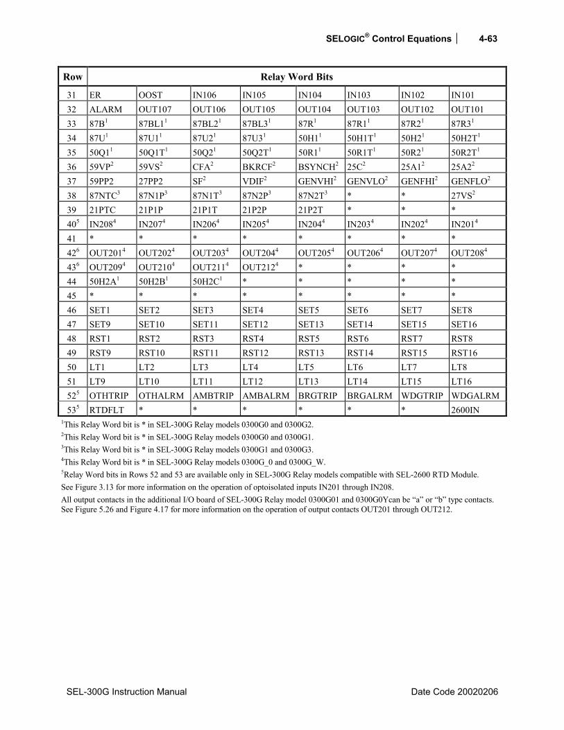
SELOGIC® Control Equations 4-63
SEL-300G Instruction Manual Date Code 20020206
Row Relay Word Bits
31 ER OOST IN106 IN105 IN104 IN103 IN102 IN101 32 ALARM OUT107 OUT106 OUT105 OUT104 OUT103 OUT102 OUT101 33 87B1 87BL11 87BL21 87BL31 87R1 87R11 87R21 87R31 34 87U1 87U11 87U21 87U31 50H11 50H1T1 50H21 50H2T1 35 50Q11 50Q1T1 50Q21 50Q2T1 50R11 50R1T1 50R21 50R2T1 36 59VP2 59VS2 CFA2 BKRCF2 BSYNCH2 25C2 25A12 25A22 37 59PP2 27PP2 SF2 VDIF2 GENVHI2 GENVLO2 GENFHI2 GENFLO2 38 87NTC3 87N1P3 87N1T3 87N2P3 87N2T3 * * 27VS2 39 21PTC 21P1P 21P1T 21P2P 21P2T * * * 405 IN2084 IN2074 IN2064 IN2054 IN2044 IN2034 IN2024 IN2014 41 * * * * * * * * 426 OUT2014 OUT2024 OUT2034 OUT2044 OUT2054 OUT2064 OUT2074 OUT2084 436 OUT2094 OUT2104 OUT2114 OUT2124 * * * * 44 50H2A1 50H2B1 50H2C1 * * * * * 45 * * * * * * * * 46 SET1 SET2 SET3 SET4 SET5 SET6 SET7 SET8 47 SET9 SET10 SET11 SET12 SET13 SET14 SET15 SET16 48 RST1 RST2 RST3 RST4 RST5 RST6 RST7 RST8 49 RST9 RST10 RST11 RST12 RST13 RST14 RST15 RST16 50 LT1 LT2 LT3 LT4 LT5 LT6 LT7 LT8 51 LT9 LT10 LT11 LT12 LT13 LT14 LT15 LT16 525 OTHTRIP OTHALRM AMBTRIP AMBALRM BRGTRIP BRGALRM WDGTRIP WDGALRM 535 RTDFLT * * * * * * 2600IN
1This Relay Word bit is * in SEL-300G Relay models 0300G0 and 0300G2. 2This Relay Word bit is * in SEL-300G Relay models 0300G0 and 0300G1. 3This Relay Word bit is * in SEL-300G Relay models 0300G1 and 0300G3. 4This Relay Word bit is * in SEL-300G Relay models 0300G_0 and 0300G_W. 5Relay Word bits in Rows 52 and 53 are available only in SEL-300G Relay models compatible with SEL-2600 RTD Module. See Figure 3.13 for more information on the operation of optoisolated inputs IN201 through IN208. All output contacts in the additional I/O board of SEL-300G Relay model 0300G01 and 0300G0Ycan be a or b type contacts. See Figure 5.26 and Figure 4.17 for more information on the operation of output contacts OUT201 through OUT212.
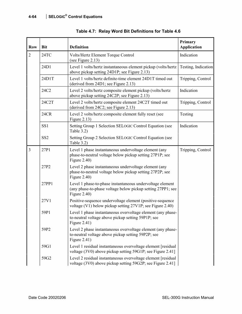
4-64 SELOGIC® Control Equations
Date Code 20020206 SEL-300G Instruction Manual
Table 4.7: Relay Word Bit Definitions for Table 4.6
Row Bit Definition Primary Application
24TC Volts/Hertz Element Torque Control (see Figure 2.13)
Indication
24D1 Level 1 volts/hertz instantaneous element pickup (volts/hertz above pickup setting 24D1P; see Figure 2.13)
Testing, Indication
24D1T Level 1 volts/hertz definite-time element 24D1T timed out (derived from 24D1; see Figure 2.13)
Tripping, Control
24C2 Level 2 volts/hertz composite element pickup (volts/hertz above pickup setting 24C2P; see Figure 2.13)
Indication
24C2T Level 2 volts/hertz composite element 24C2T timed out (derived from 24C2; see Figure 2.13)
Tripping, Control
24CR Level 2 volts/hertz composite element fully reset (see Figure 2.13)
Testing
SS1 Setting Group 1 Selection SELOGIC Control Equation (see Table 3.2)
2
SS2 Setting Group 2 Selection SELOGIC Control Equation (see Table 3.2)
Indication
27P1 Level 1 phase instantaneous undervoltage element (any phase-to-neutral voltage below pickup setting 27P1P; see Figure 2.40)
27P2 Level 2 phase instantaneous undervoltage element (any phase-to-neutral voltage below pickup setting 27P2P; see Figure 2.40)
27PP1 Level 1 phase-to-phase instantaneous undervoltage element (any phase-to-phase voltage below pickup setting 27PP1; see Figure 2.40)
27V1 Positive-sequence undervoltage element (positive-sequence voltage (V1) below pickup setting 27V1P; see Figure 2.40)
59P1 Level 1 phase instantaneous overvoltage element (any phase-to-neutral voltage above pickup setting 59P1P; see Figure 2.41)
59P2 Level 2 phase instantaneous overvoltage element (any phase-to-neutral voltage above pickup setting 59P2P; see Figure 2.41)
59G1 Level 1 residual instantaneous overvoltage element [residual voltage (3V0) above pickup setting 59G1P; see Figure 2.41]
3
59G2 Level 2 residual instantaneous overvoltage element [residual voltage (3V0) above pickup setting 59G2P; see Figure 2.41]
Tripping, Control

SELOGIC® Control Equations 4-65
SEL-300G Instruction Manual Date Code 20020206
Row Bit Definition Primary Application
32PTC Reverse/low-forward power element torque control (see Figure 2.15)
Indication
32P1 Level 1 reverse/low-forward power instantaneous element (measured three-phase real power less than pickup setting 32P1P; see Figure 2.15)
Testing, Indication
32P1T Level 1 reverse/low-forward power element time out (derived from 32P1; see Figure 2.15)
Tripping, Control
32P2 Level 2 reverse/low-forward power instantaneous element (measured three-phase real power less than pickup setting 32P2P; see Figure 2.15)
Indication
32P2T Level 2 reverse/low-forward power element time out (derived from 32P2; see Figure 2.15)
59V1 Positive-sequence overvoltage element (positive-sequence voltage (V1) above pickup setting 59V1P; see Figure 2.41)
59Q Negative-sequence instantaneous overvoltage element (negative-sequence voltage (V2) above pickup setting 59QP; see Figure 2.41)
4
59PP1 Level 1 phase-to-phase instantaneous overvoltage element (any phase-to-phase voltage above pickup setting 59PP1; see Figure 2.41)
Tripping, Control
40ZTC Loss-of-field element torque control (see Figure 2.16)
Indication
40Z1 Zone 1 instantaneous loss-of-field mho element (see Figure 2.16)
Testing, Indication
40Z1T Zone 1 time-delayed loss-of-field mho element (see Figure 2.16)
Tripping, Control
40Z2 Zone 2 instantaneous loss-of-field mho element (see Figure 2.16)
Indication
40Z2T Zone 2 time-delayed loss-of-field mho element (see Figure 2.16)
Tripping, Control
SWING Single blinder: 78R1/78R2 and 78Z1 assert Double blinder: 78R1 and 78R2 assert or only 78R1 asserts (see Figures 2.44 and 2.47)
Indication
SG1 Setting Group 1 active (see Table 3.1) Indication
5
SG2 Setting Group 2 active (see Table 3.1)
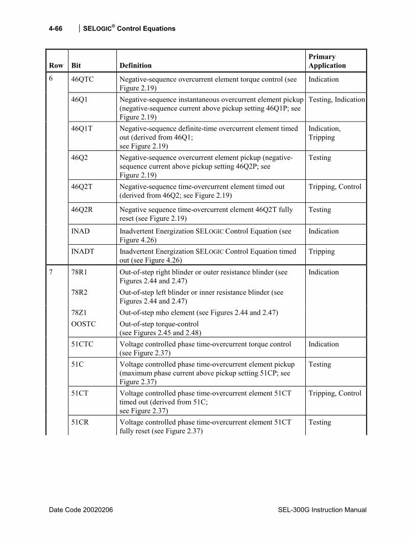
4-66 SELOGIC® Control Equations
Date Code 20020206 SEL-300G Instruction Manual
Row Bit Definition Primary Application
46QTC Negative-sequence overcurrent element torque control (see Figure 2.19)
Indication
46Q1 Negative-sequence instantaneous overcurrent element pickup (negative-sequence current above pickup setting 46Q1P; see Figure 2.19)
Testing, Indication
46Q1T Negative-sequence definite-time overcurrent element timed out (derived from 46Q1; see Figure 2.19)
Indication, Tripping
46Q2 Negative-sequence overcurrent element pickup (negative-sequence current above pickup setting 46Q2P; see Figure 2.19)
Testing
46Q2T Negative-sequence time-overcurrent element timed out (derived from 46Q2; see Figure 2.19)
Tripping, Control
46Q2R Negative sequence time-overcurrent element 46Q2T fully reset (see Figure 2.19)
Testing
INAD Inadvertent Energization SELOGIC Control Equation (see Figure 4.26)
Indication
6
INADT Inadvertent Energization SELOGIC Control Equation timed out (see Figure 4.26)
Tripping
78R1 Out-of-step right blinder or outer resistance blinder (see Figures 2.44 and 2.47)
78R2 Out-of-step left blinder or inner resistance blinder (see Figures 2.44 and 2.47)
78Z1 Out-of-step mho element (see Figures 2.44 and 2.47) OOSTC Out-of-step torque-control
(see Figures 2.45 and 2.48)
Indication
51CTC Voltage controlled phase time-overcurrent torque control (see Figure 2.37)
Indication
51C Voltage controlled phase time-overcurrent element pickup (maximum phase current above pickup setting 51CP; see Figure 2.37)
Testing
51CT Voltage controlled phase time-overcurrent element 51CT timed out (derived from 51C; see Figure 2.37)
Tripping, Control
7
51CR Voltage controlled phase time-overcurrent element 51CT fully reset (see Figure 2.37)
Testing
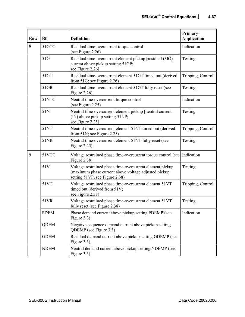
SELOGIC® Control Equations 4-67
SEL-300G Instruction Manual Date Code 20020206
Row Bit Definition Primary Application
51GTC Residual time-overcurrent torque control (see Figure 2.26)
Indication
51G Residual time-overcurrent element pickup [residual (3IO) current above pickup setting 51GP; see Figure 2.26]
Testing
51GT Residual time-overcurrent element 51GT timed out (derived from 51G; see Figure 2.26)
Tripping, Control
51GR Residual time-overcurrent element 51GT fully reset (see Figure 2.26)
Testing
51NTC Neutral time-overcurrent torque control (see Figure 2.25)
Indication
51N Neutral time-overcurrent element pickup [neutral current (IN) above pickup setting 51NP; see Figure 2.25]
Testing
51NT Neutral time-overcurrent element 51NT timed out (derived from 51N; see Figure 2.25)
Tripping, Control
8
51NR Neutral time-overcurrent element 51NT fully reset (see Figure 2.25)
Testing
51VTC Voltage restrained phase time-overcurrent torque control (see Figure 2.38)
Indication
51V Voltage restrained phase time-overcurrent element pickup (maximum phase current above voltage adjusted pickup setting 51VP; see Figure 2.38)
Testing
51VT Voltage restrained phase time-overcurrent element 51VT timed out (derived from 51V; see Figure 2.38)
Tripping, Control
51VR Voltage restrained phase time-overcurrent element 51VT fully reset (see Figure 2.38)
Testing
PDEM Phase demand current above pickup setting PDEMP (see Figure 3.3)
QDEM Negative-sequence demand current above pickup setting QDEMP (see Figure 3.3)
GDEM Residual demand current above pickup setting GDEMP (see Figure 3.3)
9
NDEM Neutral demand current above pickup setting NDEMP (see Figure 3.3)
Indication
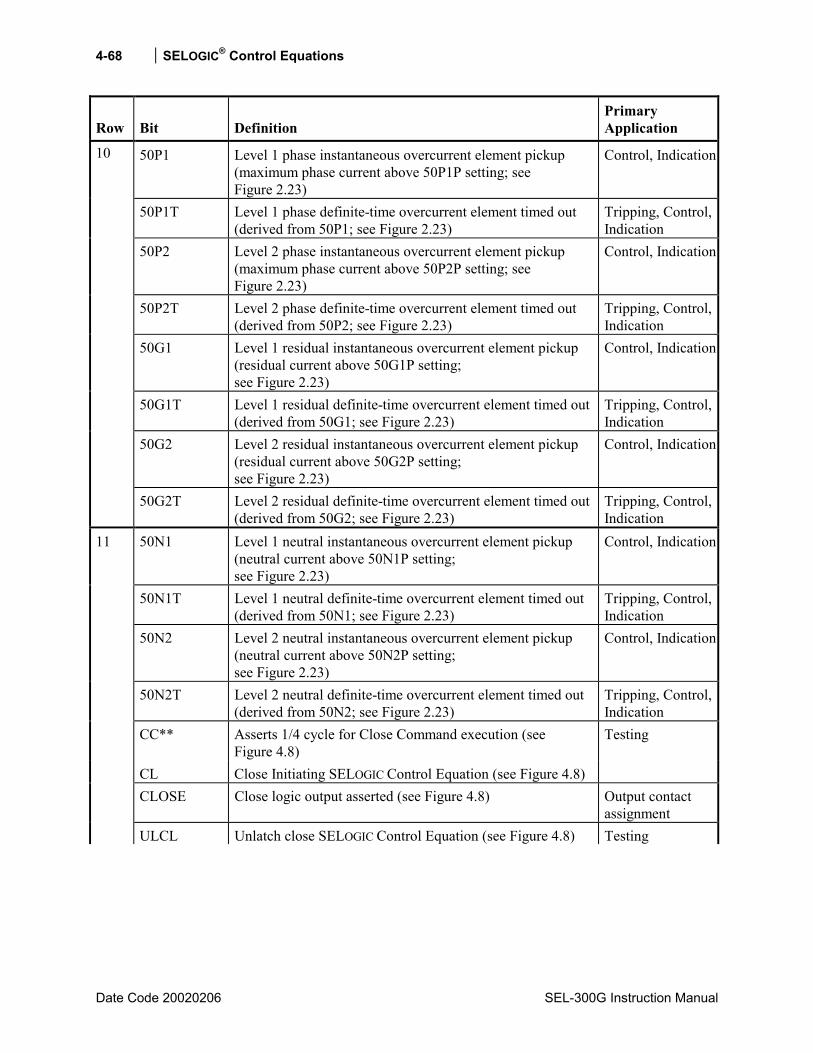
4-68 SELOGIC® Control Equations
Date Code 20020206 SEL-300G Instruction Manual
Row Bit Definition Primary Application
50P1 Level 1 phase instantaneous overcurrent element pickup (maximum phase current above 50P1P setting; see Figure 2.23)
Control, Indication
50P1T Level 1 phase definite-time overcurrent element timed out (derived from 50P1; see Figure 2.23)
Tripping, Control, Indication
50P2 Level 2 phase instantaneous overcurrent element pickup (maximum phase current above 50P2P setting; see Figure 2.23)
Control, Indication
50P2T Level 2 phase definite-time overcurrent element timed out (derived from 50P2; see Figure 2.23)
Tripping, Control, Indication
50G1 Level 1 residual instantaneous overcurrent element pickup (residual current above 50G1P setting; see Figure 2.23)
Control, Indication
50G1T Level 1 residual definite-time overcurrent element timed out (derived from 50G1; see Figure 2.23)
Tripping, Control, Indication
50G2 Level 2 residual instantaneous overcurrent element pickup (residual current above 50G2P setting; see Figure 2.23)
Control, Indication
10
50G2T Level 2 residual definite-time overcurrent element timed out (derived from 50G2; see Figure 2.23)
Tripping, Control, Indication
50N1 Level 1 neutral instantaneous overcurrent element pickup (neutral current above 50N1P setting; see Figure 2.23)
Control, Indication
50N1T Level 1 neutral definite-time overcurrent element timed out (derived from 50N1; see Figure 2.23)
Tripping, Control, Indication
50N2 Level 2 neutral instantaneous overcurrent element pickup (neutral current above 50N2P setting; see Figure 2.23)
Control, Indication
50N2T Level 2 neutral definite-time overcurrent element timed out (derived from 50N2; see Figure 2.23)
Tripping, Control, Indication
CC** Asserts 1/4 cycle for Close Command execution (see Figure 4.8)
CL Close Initiating SELOGIC Control Equation (see Figure 4.8)
Testing
CLOSE Close logic output asserted (see Figure 4.8) Output contact assignment
11
ULCL Unlatch close SELOGIC Control Equation (see Figure 4.8) Testing

SELOGIC® Control Equations 4-69
SEL-300G Instruction Manual Date Code 20020206
Row Bit Definition Primary Application
64GTC 100% stator ground element torque control (see Figure 2.43)
Indication
64G1 Zone 1 neutral overvoltage stator ground fault element (neutral voltage above pickup setting 64G1P; see Figure 2.43)
Testing, Indication
64G1T Zone 1 stator ground fault element timed out (derived from 64G1; see Figure 2.43)
Tripping, Control
64G2 Zone 2 third-harmonic voltage stator ground fault element (third-harmonic voltage differential above or third-harmonic neutral voltage below pickup setting 64G2P; see Figure 2.43)
Testing, Indication
64G2T Zone 2 stator ground fault element timed out (derived from 64G2; see Figure 2.43)
Tripping, Control
OOS Out-of-step element (see Figures 2.45 and 2.48) Indication 60LOP Loss of relaying potential Indication, Control
12
CLEN Close Enable SELOGIC Control Equation (see Figure 4.8) Indication BKMON Breaker Monitor initiating control equation
(see Figure 3.11) Testing
BCW BCW = BCWA + BCWB + BCWC BCWA A-phase breaker contact wear has reached 100% wear level
(see Breaker Monitor in Section 3: Auxiliary Function Settings)
BCWB B-phase breaker contact wear has reached 100% wear level (see Breaker Monitor in Section 3: Auxiliary Function Settings)
BCWC C-phase breaker contact wear has reached 100% wear level (see Breaker Monitor in Section 3: Auxiliary Function Settings)
FAULT Generator fault indication (halts Max/Min METER recording)
DCLO Station dc battery instantaneous undervoltage element (see Figure 3.4)
13
DCHI Station dc battery instantaneous overvoltage element (see Figure 3.4)
Indication
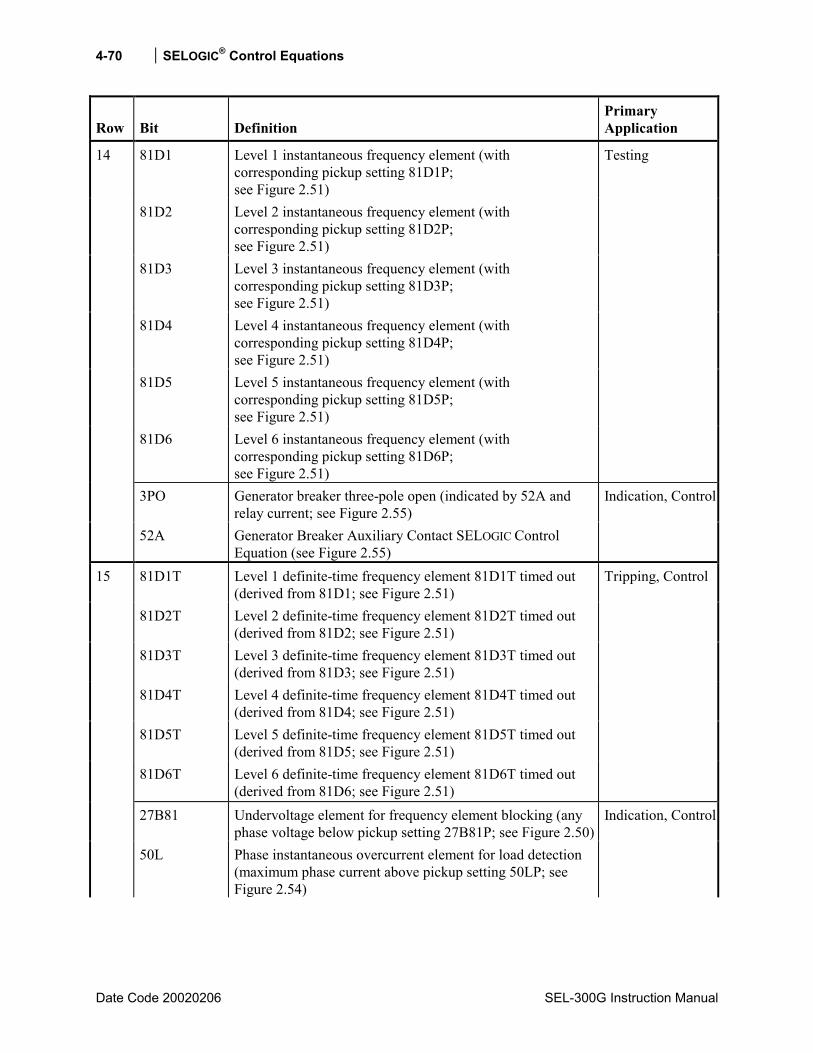
4-70 SELOGIC® Control Equations
Date Code 20020206 SEL-300G Instruction Manual
Row Bit Definition Primary Application
81D1 Level 1 instantaneous frequency element (with corresponding pickup setting 81D1P; see Figure 2.51)
81D2 Level 2 instantaneous frequency element (with corresponding pickup setting 81D2P; see Figure 2.51)
81D3 Level 3 instantaneous frequency element (with corresponding pickup setting 81D3P; see Figure 2.51)
81D4 Level 4 instantaneous frequency element (with corresponding pickup setting 81D4P; see Figure 2.51)
81D5 Level 5 instantaneous frequency element (with corresponding pickup setting 81D5P; see Figure 2.51)
81D6 Level 6 instantaneous frequency element (with corresponding pickup setting 81D6P; see Figure 2.51)
Testing
3PO Generator breaker three-pole open (indicated by 52A and relay current; see Figure 2.55)
14
52A Generator Breaker Auxiliary Contact SELOGIC Control Equation (see Figure 2.55)
Indication, Control
81D1T Level 1 definite-time frequency element 81D1T timed out (derived from 81D1; see Figure 2.51)
81D2T Level 2 definite-time frequency element 81D2T timed out (derived from 81D2; see Figure 2.51)
81D3T Level 3 definite-time frequency element 81D3T timed out (derived from 81D3; see Figure 2.51)
81D4T Level 4 definite-time frequency element 81D4T timed out (derived from 81D4; see Figure 2.51)
81D5T Level 5 definite-time frequency element 81D5T timed out (derived from 81D5; see Figure 2.51)
81D6T Level 6 definite-time frequency element 81D6T timed out (derived from 81D6; see Figure 2.51)
Tripping, Control
27B81 Undervoltage element for frequency element blocking (any phase voltage below pickup setting 27B81P; see Figure 2.50)
15
50L Phase instantaneous overcurrent element for load detection (maximum phase current above pickup setting 50LP; see Figure 2.54)
Indication, Control
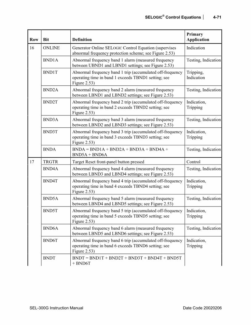
SELOGIC® Control Equations 4-71
SEL-300G Instruction Manual Date Code 20020206
Row Bit Definition Primary Application
ONLINE Generator Online SELOGIC Control Equation (supervises abnormal frequency protection scheme; see Figure 2.53)
Indication
BND1A Abnormal frequency band 1 alarm (measured frequency between UBND1 and LBND1 settings; see Figure 2.53)
Testing, Indication
BND1T Abnormal frequency band 1 trip (accumulated off-frequency operating time in band 1 exceeds TBND1 setting; see Figure 2.53)
Tripping, Indication
BND2A Abnormal frequency band 2 alarm (measured frequency between LBND1 and LBND2 settings; see Figure 2.53)
Testing, Indication
BND2T Abnormal frequency band 2 trip (accumulated off-frequency operating time in band 2 exceeds TBND2 setting; see Figure 2.53)
Indication, Tripping
BND3A Abnormal frequency band 3 alarm (measured frequency between LBND2 and LBND3 settings; see Figure 2.53)
Testing, Indication
BND3T Abnormal frequency band 3 trip (accumulated off-frequency operating time in band 3 exceeds TBND3 setting; see Figure 2.53)
Indication, Tripping
16
BNDA BNDA = BND1A + BND2A + BND3A + BND4A + BND5A + BND6A
Testing, Indication
TRGTR Target Reset front-panel button pressed Control BND4A Abnormal frequency band 4 alarm (measured frequency
between LBND3 and LBND4 settings; see Figure 2.53) Testing, Indication
BND4T Abnormal frequency band 4 trip (accumulated off-frequency operating time in band 4 exceeds TBND4 setting; see Figure 2.53)
Indication, Tripping
BND5A Abnormal frequency band 5 alarm (measured frequency between LBND4 and LBND5 settings; see Figure 2.53)
Testing, Indication
BND5T Abnormal frequency band 5 trip (accumulated off-frequency operating time in band 5 exceeds TBND5 setting; see Figure 2.53)
Indication, Tripping
BND6A Abnormal frequency band 6 alarm (measured frequency between LBND5 and LBND6 settings; see Figure 2.53)
Testing, Indication
BND6T Abnormal frequency band 6 trip (accumulated off-frequency operating time in band 6 exceeds TBND6 setting; see Figure 2.53)
17
BNDT BNDT = BND1T + BND2T + BND3T + BND4T + BND5T + BND6T
Indication, Tripping

4-72 SELOGIC® Control Equations
Date Code 20020206 SEL-300G Instruction Manual
Row Bit Definition Primary Application
TRIP TRIP = TRIP1 + TRIP2 + TRIP3 + TRIP4 Indication TRIP1 TRIP1 logic output asserted (see Figure 4.6) TRIP2 TRIP2 logic output asserted (see Figure 4.6) TRIP3 TRIP3 logic output asserted (see Figure 4.6) TRIP4 TRIP4 logic output asserted (see Figure 4.6)
Output contact assignment
OC1** Asserts 1/4 cycle for OPEN 1 Command execution (see Figure 4.6)
OC2** Asserts 1/4 cycle for OPEN 2 Command execution (see Figure 4.6)
18
OC3** Asserts 1/4 cycle for OPEN 3 Command execution (see Figure 4.6)
Testing
TR1 SELOGIC Control Equation to initiate TRIP1 (see Figure 4.6)
TR2 SELOGIC Control Equation to initiate TRIP2 (see Figure 4.6)
TR3 SELOGIC Control Equation to initiate TRIP3 (see Figure 4.6)
TR4 SELOGIC Control Equation to initiate TRIP4 (see Figure 4.6)
ULTR1 SELOGIC Control Equation to unlatch TRIP1 (see Figure 4.6)
ULTR2 SELOGIC Control Equation to unlatch TRIP2 (see Figure 4.6)
ULTR3 SELOGIC Control Equation to unlatch TRIP3 (see Figure 4.6)
19
ULTR4 SELOGIC Control Equation to unlatch TRIP4 (see Figure 4.6)
Testing
20 LB1 LB2 LB3 LB4 LB5 LB6 LB7 LB8
Local Bit 1 asserted (see Figure 4.18) Local Bit 2 asserted (see Figure 4.18) Local Bit 3 asserted (see Figure 4.18) Local Bit 4 asserted (see Figure 4.18) Local Bit 5 asserted (see Figure 4.18) Local Bit 6 asserted (see Figure 4.18) Local Bit 7 asserted (see Figure 4.18) Local Bit 8 asserted (see Figure 4.18)
Control via front panel replacing traditional panel-mounted control switches
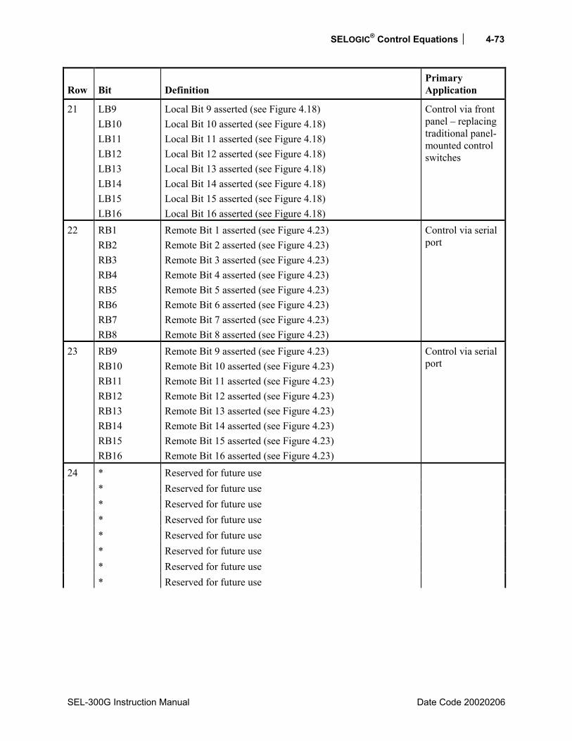
SELOGIC® Control Equations 4-73
SEL-300G Instruction Manual Date Code 20020206
Row Bit Definition Primary Application
21 LB9 LB10 LB11 LB12 LB13 LB14 LB15 LB16
Local Bit 9 asserted (see Figure 4.18) Local Bit 10 asserted (see Figure 4.18) Local Bit 11 asserted (see Figure 4.18) Local Bit 12 asserted (see Figure 4.18) Local Bit 13 asserted (see Figure 4.18) Local Bit 14 asserted (see Figure 4.18) Local Bit 15 asserted (see Figure 4.18) Local Bit 16 asserted (see Figure 4.18)
Control via front panel replacing traditional panel-mounted control switches
22 RB1 RB2 RB3 RB4 RB5 RB6 RB7 RB8
Remote Bit 1 asserted (see Figure 4.23) Remote Bit 2 asserted (see Figure 4.23) Remote Bit 3 asserted (see Figure 4.23) Remote Bit 4 asserted (see Figure 4.23) Remote Bit 5 asserted (see Figure 4.23) Remote Bit 6 asserted (see Figure 4.23) Remote Bit 7 asserted (see Figure 4.23) Remote Bit 8 asserted (see Figure 4.23)
Control via serial port
23 RB9 RB10 RB11 RB12 RB13 RB14 RB15 RB16
Remote Bit 9 asserted (see Figure 4.23) Remote Bit 10 asserted (see Figure 4.23) Remote Bit 11 asserted (see Figure 4.23) Remote Bit 12 asserted (see Figure 4.23) Remote Bit 13 asserted (see Figure 4.23) Remote Bit 14 asserted (see Figure 4.23) Remote Bit 15 asserted (see Figure 4.23) Remote Bit 16 asserted (see Figure 4.23)
Control via serial port
* Reserved for future use * Reserved for future use * Reserved for future use * Reserved for future use * Reserved for future use * Reserved for future use * Reserved for future use
24
* Reserved for future use

4-74 SELOGIC® Control Equations
Date Code 20020206 SEL-300G Instruction Manual
Row Bit Definition Primary Application
SV1 SELOGIC Control Equation variable timer input SV1 asserted (see Figure 4.2)
SV2 SELOGIC Control Equation variable timer input SV2 asserted (see Figure 4.2)
SV3 SELOGIC Control Equation variable timer input SV3 asserted (see Figure 4.2)
SV4 SELOGIC Control Equation variable timer input SV4 asserted (see Figure 4.2)
Testing, seal-in functions, etc.
SV1T SELOGIC Control Equation variable timer output SV1T asserted (see Figure 4.2)
SV2T SELOGIC Control Equation variable timer output SV2T asserted (see Figure 4.2)
SV3T SELOGIC Control Equation variable timer output SV3T asserted (see Figure 4.2)
25
SV4T SELOGIC Control Equation variable timer output SV4T asserted (see Figure 4.2)
Control
SV5 SELOGIC Control Equation variable timer input SV5 asserted (see Figure 4.2)
SV6 SELOGIC Control Equation variable timer input SV6 asserted (see Figure 4.2)
SV7 SELOGIC Control Equation variable timer input SV7 asserted (see Figure 4.2)
SV8 SELOGIC Control Equation variable timer input SV8 asserted (see Figure 4.2)
Testing, seal-in functions, etc.
SV5T SELOGIC Control Equation variable timer output SV5T asserted (see Figure 4.2)
SV6T SELOGIC Control Equation variable timer output SV6T asserted (see Figure 4.2)
SV7T SELOGIC Control Equation variable timer output SV7T asserted (see Figure 4.2)
26
SV8T SELOGIC Control Equation variable timer output SV8T asserted (see Figure 4.2)
Control
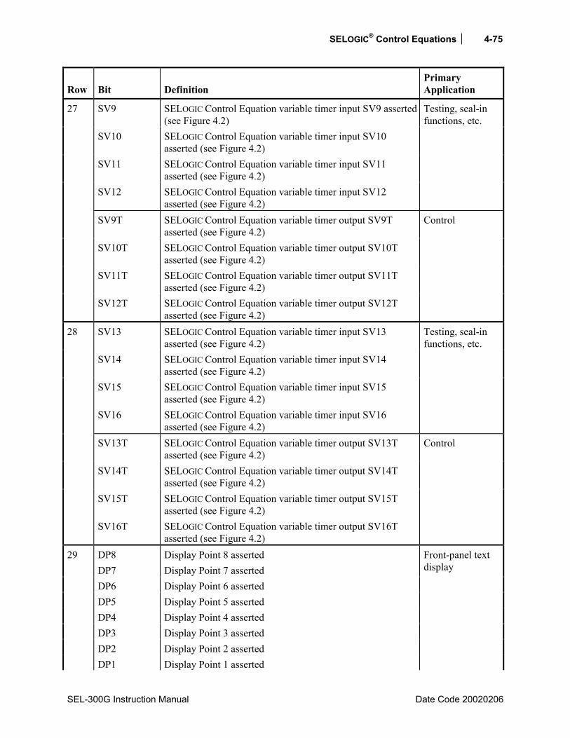
SELOGIC® Control Equations 4-75
SEL-300G Instruction Manual Date Code 20020206
Row Bit Definition Primary Application
SV9 SELOGIC Control Equation variable timer input SV9 asserted (see Figure 4.2)
SV10 SELOGIC Control Equation variable timer input SV10 asserted (see Figure 4.2)
SV11 SELOGIC Control Equation variable timer input SV11 asserted (see Figure 4.2)
SV12 SELOGIC Control Equation variable timer input SV12 asserted (see Figure 4.2)
Testing, seal-in functions, etc.
SV9T SELOGIC Control Equation variable timer output SV9T asserted (see Figure 4.2)
SV10T SELOGIC Control Equation variable timer output SV10T asserted (see Figure 4.2)
SV11T SELOGIC Control Equation variable timer output SV11T asserted (see Figure 4.2)
27
SV12T SELOGIC Control Equation variable timer output SV12T asserted (see Figure 4.2)
Control
SV13 SELOGIC Control Equation variable timer input SV13 asserted (see Figure 4.2)
SV14 SELOGIC Control Equation variable timer input SV14 asserted (see Figure 4.2)
SV15 SELOGIC Control Equation variable timer input SV15 asserted (see Figure 4.2)
SV16 SELOGIC Control Equation variable timer input SV16 asserted (see Figure 4.2)
Testing, seal-in functions, etc.
SV13T SELOGIC Control Equation variable timer output SV13T asserted (see Figure 4.2)
SV14T SELOGIC Control Equation variable timer output SV14T asserted (see Figure 4.2)
SV15T SELOGIC Control Equation variable timer output SV15T asserted (see Figure 4.2)
28
SV16T SELOGIC Control Equation variable timer output SV16T asserted (see Figure 4.2)
Control
DP8 Display Point 8 asserted DP7 Display Point 7 asserted DP6 Display Point 6 asserted DP5 Display Point 5 asserted DP4 Display Point 4 asserted DP3 Display Point 3 asserted DP2 Display Point 2 asserted
29
DP1 Display Point 1 asserted
Front-panel text display
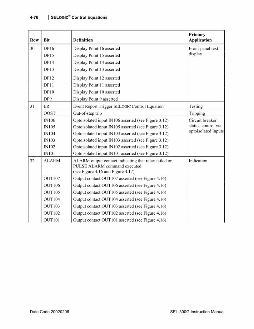
4-76 SELOGIC® Control Equations
Date Code 20020206 SEL-300G Instruction Manual
Row Bit Definition Primary Application
DP16 Display Point 16 asserted DP15 Display Point 15 asserted DP14 Display Point 14 asserted DP13 Display Point 13 asserted
DP12 Display Point 12 asserted DP11 Display Point 11 asserted DP10 Display Point 10 asserted
30
DP9 Display Point 9 asserted
Front-panel text display
ER Event Report Trigger SELOGIC Control Equation Testing OOST Out-of-step trip Tripping
31
IN106 IN105 IN104 IN103 IN102 IN101
Optoisolated input IN106 asserted (see Figure 3.12) Optoisolated input IN105 asserted (see Figure 3.12) Optoisolated input IN104 asserted (see Figure 3.12) Optoisolated input IN103 asserted (see Figure 3.12) Optoisolated input IN102 asserted (see Figure 3.12) Optoisolated input IN101 asserted (see Figure 3.12)
Circuit breaker status, control via optoisolated inputs
ALARM ALARM output contact indicating that relay failed or PULSE ALARM command executed (see Figure 4.16 and Figure 4.17)
OUT107 Output contact OUT107 asserted (see Figure 4.16) OUT106 Output contact OUT106 asserted (see Figure 4.16) OUT105 Output contact OUT105 asserted (see Figure 4.16) OUT104 Output contact OUT104 asserted (see Figure 4.16) OUT103 Output contact OUT103 asserted (see Figure 4.16) OUT102 Output contact OUT102 asserted (see Figure 4.16)
32
OUT101 Output contact OUT101 asserted (see Figure 4.16)
Indication
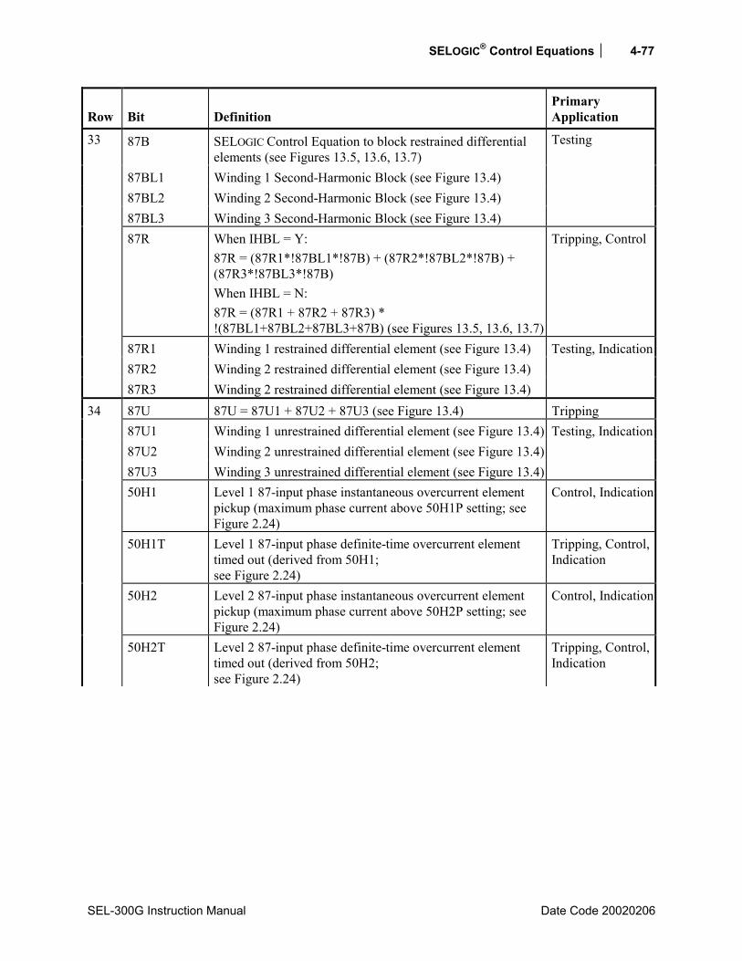
SELOGIC® Control Equations 4-77
SEL-300G Instruction Manual Date Code 20020206
Row Bit Definition Primary Application
87B SELOGIC Control Equation to block restrained differential elements (see Figures 13.5, 13.6, 13.7)
87BL1 Winding 1 Second-Harmonic Block (see Figure 13.4) 87BL2 Winding 2 Second-Harmonic Block (see Figure 13.4) 87BL3 Winding 3 Second-Harmonic Block (see Figure 13.4)
Testing
87R When IHBL = Y: 87R = (87R1*!87BL1*!87B) + (87R2*!87BL2*!87B) + (87R3*!87BL3*!87B) When IHBL = N: 87R = (87R1 + 87R2 + 87R3) * !(87BL1+87BL2+87BL3+87B) (see Figures 13.5, 13.6, 13.7)
Tripping, Control
87R1 Winding 1 restrained differential element (see Figure 13.4) 87R2 Winding 2 restrained differential element (see Figure 13.4)
33
87R3 Winding 2 restrained differential element (see Figure 13.4)
Testing, Indication
87U 87U = 87U1 + 87U2 + 87U3 (see Figure 13.4) Tripping 87U1 Winding 1 unrestrained differential element (see Figure 13.4) 87U2 Winding 2 unrestrained differential element (see Figure 13.4) 87U3 Winding 3 unrestrained differential element (see Figure 13.4)
Testing, Indication
50H1 Level 1 87-input phase instantaneous overcurrent element pickup (maximum phase current above 50H1P setting; see Figure 2.24)
Control, Indication
50H1T Level 1 87-input phase definite-time overcurrent element timed out (derived from 50H1; see Figure 2.24)
Tripping, Control, Indication
50H2 Level 2 87-input phase instantaneous overcurrent element pickup (maximum phase current above 50H2P setting; see Figure 2.24)
Control, Indication
34
50H2T Level 2 87-input phase definite-time overcurrent element timed out (derived from 50H2; see Figure 2.24)
Tripping, Control, Indication
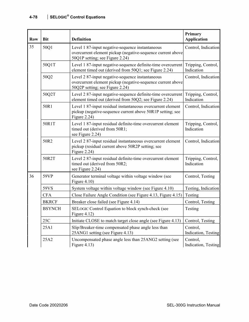
4-78 SELOGIC® Control Equations
Date Code 20020206 SEL-300G Instruction Manual
Row Bit Definition Primary Application
50Q1 Level 1 87-input negative-sequence instantaneous overcurrent element pickup (negative-sequence current above 50Q1P setting; see Figure 2.24)
Control, Indication
50Q1T Level 1 87-input negative-sequence definite-time overcurrent element timed out (derived from 50Q1; see Figure 2.24)
Tripping, Control, Indication
50Q2 Level 2 87-input negative-sequence instantaneous overcurrent element pickup (negative-sequence current above 50Q2P setting; see Figure 2.24)
Control, Indication
50Q2T Level 2 87-input negative-sequence definite-time overcurrent element timed out (derived from 50Q2; see Figure 2.24)
Tripping, Control, Indication
50R1 Level 1 87-input residual instantaneous overcurrent element pickup (negative-sequence current above 50R1P setting; see Figure 2.24)
Control, Indication
50R1T Level 1 87-input residual definite-time overcurrent element timed out (derived from 50R1; see Figure 2.24)
Tripping, Control, Indication
50R2 Level 2 87-input residual instantaneous overcurrent element pickup (residual current above 50R2P setting; see Figure 2.24)
Control, Indication
35
50R2T Level 2 87-input residual definite-time overcurrent element timed out (derived from 50R2; see Figure 2.24)
Tripping, Control, Indication
59VP Generator terminal voltage within voltage window (see Figure 4.10)
Control, Testing
59VS System voltage within voltage window (see Figure 4.10) Testing, IndicationCFA Close Failure Angle Condition (see Figure 4.13, Figure 4.15) Testing BKRCF Breaker close failed (see Figure 4.14) Control, Testing BSYNCH SELOGIC Control Equation to block synch-check (see
Figure 4.12) Testing
25C Initiate CLOSE to match target close angle (see Figure 4.13) Control, Testing 25A1 Slip/Breaker-time compensated phase angle less than
25ANG1 setting (see Figure 4.13) Control, Indication, Testing
36
25A2 Uncompensated phase angle less than 25ANG2 setting (see Figure 4.13)
Control, Indication, Testing

SELOGIC® Control Equations 4-79
SEL-300G Instruction Manual Date Code 20020206
Row Bit Definition Primary Application
59PP2 Level 2 phase-to-phase instantaneous overvoltage element (any phase-to-phase voltage above pickup setting 59PP2; see Figure 2.41)
27PP2 Level 2 phase-to-phase instantaneous undervoltage element (any phase-to-phase voltage below pickup setting 27PP2; see Figure 2.40)
SF Slip frequency within acceptable bounds (see Figure 4.12)
Control, Indication
VDIF Generator and system voltage difference within acceptable bounds (see Figure 4.10)
GENVHI Generator Voltage greater than system voltage (see Figure 4.10)
GENVLO Generator voltage less than system voltage (see Figure 4.10) GENFHI Slip frequency greater than 25SHI setting (see Figure 4.12)
37
GENFLO Slip frequency less than 25SLO setting (see Figure 4.12)
Indication, Testing
87NTC Ground differential torque control (see Figure 13.1) Indication 87N1P Level 1 ground differential instantaneous element pickup
(see Figure 13.1) Control, Indication
87N1T Level 1 ground differential element timed out (see Figure 13.1)
Tripping
87N2P Level 2 ground differential instantaneous element pickup (see Figure 13.1)
Control, Indication
87N2T Level 2 ground differential element timed out (see Figure 13.1)
* Reserved for future use * Reserved for future use
Tripping
38
27VS Synch voltage input (VS) undervoltage (see Figure 4.10) Indication, Control21PTC Phase distance element torque control (see Figure 2.7) Indication 21P1P Zone 1 phase distance element instantaneous pickup (see
Figure 2.7) Control, Indication
21P1T Zone 1 phase distance element timed out (see Figure 2.7) Tripping 21P2P Zone 2 phase distance element instantaneous pickup (see
Figure 2.7) Control, Indication
21P2T Zone 2 phase distance element timed out (see Figure 2.7) * Reserved for future use * Reserved for future use
39
* Reserved for future use
Tripping
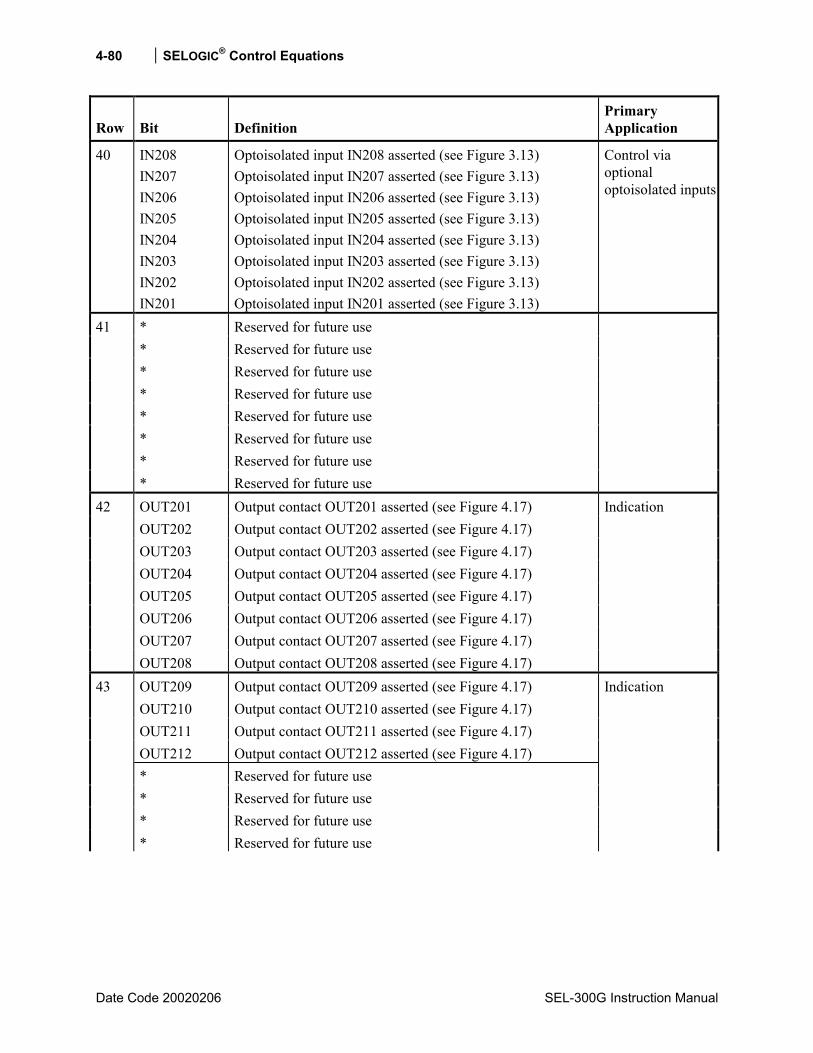
4-80 SELOGIC® Control Equations
Date Code 20020206 SEL-300G Instruction Manual
Row Bit Definition Primary Application
40 IN208 IN207 IN206 IN205 IN204 IN203 IN202 IN201
Optoisolated input IN208 asserted (see Figure 3.13) Optoisolated input IN207 asserted (see Figure 3.13) Optoisolated input IN206 asserted (see Figure 3.13) Optoisolated input IN205 asserted (see Figure 3.13) Optoisolated input IN204 asserted (see Figure 3.13) Optoisolated input IN203 asserted (see Figure 3.13) Optoisolated input IN202 asserted (see Figure 3.13) Optoisolated input IN201 asserted (see Figure 3.13)
Control via optional optoisolated inputs
* Reserved for future use * Reserved for future use * Reserved for future use * Reserved for future use * Reserved for future use * Reserved for future use * Reserved for future use
41
* Reserved for future use OUT201 Output contact OUT201 asserted (see Figure 4.17) OUT202 Output contact OUT202 asserted (see Figure 4.17) OUT203 Output contact OUT203 asserted (see Figure 4.17) OUT204 Output contact OUT204 asserted (see Figure 4.17) OUT205 Output contact OUT205 asserted (see Figure 4.17) OUT206 Output contact OUT206 asserted (see Figure 4.17) OUT207 Output contact OUT207 asserted (see Figure 4.17)
42
OUT208 Output contact OUT208 asserted (see Figure 4.17)
Indication
OUT209 Output contact OUT209 asserted (see Figure 4.17) OUT210 Output contact OUT210 asserted (see Figure 4.17) OUT211 Output contact OUT211 asserted (see Figure 4.17) OUT212 Output contact OUT212 asserted (see Figure 4.17) * Reserved for future use * Reserved for future use * Reserved for future use
43
* Reserved for future use
Indication
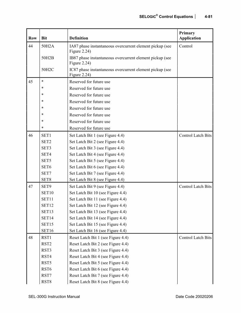
SELOGIC® Control Equations 4-81
SEL-300G Instruction Manual Date Code 20020206
Row Bit Definition Primary Application
50H2A IA87 phase instantaneous overcurrent element pickup (see Figure 2.24)
50H2B IB87 phase instantaneous overcurrent element pickup (see Figure 2.24)
44
50H2C IC87 phase instantaneous overcurrent element pickup (see Figure 2.24)
Control
* Reserved for future use * Reserved for future use * Reserved for future use * Reserved for future use * Reserved for future use * Reserved for future use * Reserved for future use
45
* Reserved for future use
46 SET1 SET2 SET3 SET4 SET5 SET6 SET7 SET8
Set Latch Bit 1 (see Figure 4.4) Set Latch Bit 2 (see Figure 4.4) Set Latch Bit 3 (see Figure 4.4) Set Latch Bit 4 (see Figure 4.4) Set Latch Bit 5 (see Figure 4.4) Set Latch Bit 6 (see Figure 4.4) Set Latch Bit 7 (see Figure 4.4) Set Latch Bit 8 (see Figure 4.4)
Control Latch Bits
47 SET9 SET10 SET11 SET12 SET13 SET14 SET15 SET16
Set Latch Bit 9 (see Figure 4.4) Set Latch Bit 10 (see Figure 4.4) Set Latch Bit 11 (see Figure 4.4) Set Latch Bit 12 (see Figure 4.4) Set Latch Bit 13 (see Figure 4.4) Set Latch Bit 14 (see Figure 4.4) Set Latch Bit 15 (see Figure 4.4) Set Latch Bit 16 (see Figure 4.4)
Control Latch Bits
48 RST1 RST2 RST3 RST4 RST5 RST6 RST7 RST8
Reset Latch Bit 1 (see Figure 4.4) Reset Latch Bit 2 (see Figure 4.4) Reset Latch Bit 3 (see Figure 4.4) Reset Latch Bit 4 (see Figure 4.4) Reset Latch Bit 5 (see Figure 4.4) Reset Latch Bit 6 (see Figure 4.4) Reset Latch Bit 7 (see Figure 4.4) Reset Latch Bit 8 (see Figure 4.4)
Control Latch Bits

4-82 SELOGIC® Control Equations
Date Code 20020206 SEL-300G Instruction Manual
Row Bit Definition Primary Application
49 RST9 RST10 RST11 RST12 RST13 RST14 RST15 RST16
Reset Latch Bit 9 (see Figure 4.4) Reset Latch Bit 10 (see Figure 4.4) Reset Latch Bit 11 (see Figure 4.4) Reset Latch Bit 12 (see Figure 4.4) Reset Latch Bit 13 (see Figure 4.4) Reset Latch Bit 14 (see Figure 4.4) Reset Latch Bit 15 (see Figure 4.4) Reset Latch Bit 16 (see Figure 4.4)
Control Latch Bits
50 LT1 LT2 LT3 LT4 LT5 LT6 LT7 LT8
Latch Bit 1 asserted (see Figure 4.4) Latch Bit 2 asserted (see Figure 4.4) Latch Bit 3 asserted (see Figure 4.4) Latch Bit 4 asserted (see Figure 4.4) Latch Bit 5 asserted (see Figure 4.4) Latch Bit 6 asserted (see Figure 4.4) Latch Bit 7 asserted (see Figure 4.4) Latch Bit 8 asserted (see Figure 4.4)
Control via SELOGIC Control Equation replacing traditional panel-mounted latching relays
51 LT9 LT10 LT11 LT12 LT13 LT14 LT15 LT16
Latch Bit 9 asserted (see Figure 4.4) Latch Bit 10 asserted (see Figure 4.4) Latch Bit 11 asserted (see Figure 4.4) Latch Bit 12 asserted (see Figure 4.4) Latch Bit 13 asserted (see Figure 4.4) Latch Bit 14 asserted (see Figure 4.4) Latch Bit 15 asserted (see Figure 4.4) Latch Bit 16 asserted (see Figure 4.4)
Control via SELOGIC Control Equation replacing traditional panel-mounted latching relays

SELOGIC® Control Equations 4-83
SEL-300G Instruction Manual Date Code 20020206
Row Bit Definition Primary Application
OTHTRIP OTHALRM
Other Temperature Trip and Alarm. OTHTRIP asserts when any healthy other RTD temperature exceeds its trip setpoint. BRGALRM asserts when any healthy other RTD temperature exceeds its alarm setpoint.
Tripping, Indication, SER Triggering
AMBTRIP AMBALRM
Ambient Temperature Trip and Alarm. AMBTRIP asserts when the healthy ambient RTD temperature exceeds its trip setpoint. AMBALRM asserts when the healthy ambient RTD temperature exceeds its alarm setpoint.
Tripping, Indication, SER Triggering
BRGTRIP BRGALRM
Bearing Temperature Trip and Alarm. BRGTRIP asserts when one or two (when EBRGV = Y) healthy winding RTD temperatures exceed their trip setpoints. BRGALRM asserts when any healthy bearing RTD temperature exceeds its alarm setpoint.
Tripping, Indication, SER Triggering
52
WDGTRIP WDGALRM
Winding Temperature Trip and Alarm. WDGTRIP asserts when one or two (when EWDGV = Y) healthy winding RTD temperatures exceed their trip or biased trip (when RTDBIAS ≠ NONE) setpoints. WDGALRM asserts when any healthy winding RTD temperature exceeds its alarm setpoint.
Tripping, Indication, SER Triggering
RTDFLT Asserts when an open or short circuit condition is detected on any enabled RTD input, or communication with the SEL-2600 RTD Module has been interrupted.
Indication, SER Triggering
53
2600IN Contact input 2600IN from the SEL-2600 RTD Module. Control, Indication** The Open Command (Relay Word bit OCn) and Close Command (Relay Word bit CC) are already embedded in the Trip Logic (see Figure 4.6) and Close Logic (see Figure 4.8), respectively. Thus, they likely are not used in SELOGIC Control Equations. They are in the Relay Word for embedded event report information functions.

SEL-300G Instruction Manual Date Code 20020206
TABLE OF CONTENTS
SECTION 5: INSTALLATION .............................................................5-1
Relay Mounting.............................................................................................................................5-1 Making Rear-Panel Connections.................................................................................................5-12
Required Equipment and General Connect Information.....................................................5-12 Models 0300G_W and 0300G_Y (Connectorized).....................................................5-12
Wiring Harness ....................................................................................................5-12 Models 0300G_0 and 000G_1 (screw-terminal blocks) .............................................5-15
Chassis Ground ...................................................................................................................5-15 Models 0300G_W and 000G_Y..................................................................................5-15 Models 0300G_0 and 0300G_1...................................................................................5-15
Power Supply ......................................................................................................................5-15 Models 0300G_W and 0300G_Y................................................................................5-15 Models 0300G_0 and 000G_1.....................................................................................5-15
Output Contacts...................................................................................................................5-15 Models 0300G_0H, 0300G_03, 0300G_WH, and 0300G_W3 ..................................5-15 Models 0300G_1H, 0300G_13, 0300G_YH, and 0300G_Y3 ....................................5-16 Standard Output Contacts............................................................................................5-16 High Current Interrupting Output Contacts.................................................................5-16
Optoisolated Inputs .............................................................................................................5-17 Current Transformer Inputs (screw-terminal block models)...............................................5-17
Models 0300G0, 0300G1, 0300G2, and 0300G3........................................................5-17 Models 0300G1 and 0300G3.......................................................................................5-17
Current Transformer Inputs (Connectorized® models) .......................................................5-17 Models 0300G0, 0300G1, 0300G2, and 0300G3........................................................5-17 Models 0300G1 and 0300G3.......................................................................................5-18
Potential Transformer Inputs...............................................................................................5-18 Serial Ports ..........................................................................................................................5-18 IRIG-B Time-Code Input ....................................................................................................5-19
Example AC and DC Connection Diagrams...............................................................................5-20 Circuit Board Jumpers and Battery.............................................................................................5-26
Accessing the Relay Main Board (All Models) and Extra I/O Board (Models 0300G_1 and 0300G_Y) .............................................................................................5-26
Output Contact Jumpers ......................................................................................................5-29 Extra Alarm Output Contact Control Jumper..................................................................5-29 Password and Breaker Jumpers...........................................................................................5-30 EIA-232 Serial Port Voltage Jumpers .................................................................................5-31
Condition of Acceptability for North American Product Safety Compliance ............5-31 Clock Battery.......................................................................................................................5-32

ii Installation
Date Code 20020206 SEL-300G Instruction Manual
TABLES Table 5.1: Communication Cables to Connect the SEL-300G Relay to Other Devices........................5-19 Table 5.2: Output Contact Jumpers and Corresponding Output Contacts..............................................5-29 Table 5.3: Extra Alarm Output Contacts and Corresponding Controlling Jumpers ...........................5-29 Table 5.4: Required Position of Jumper JMP23 for Desired Output Contact OUT107 Operation
(Models 0300G_0 and 0300G_1) .......................................................................................5-30 Table 5.5: Password and Breaker Jumper Positions for Standard Relay Shipments ..............................5-30 Table 5.6: Password and Breaker Jumper Operation..............................................................................5-31 Table 5.7: EIA-232 Serial Port Voltage Jumper Positions for Standard Relay Shipments ....................5-31
FIGURES Figure 5.1: SEL-300G Relay Dimensions and Panel Mount Cut-Out.....................................................5-1 Figure 5.2: SEL-300G Relay Front-Panel Drawings for Rack-Mount Relays (2U and 3U),
Screw-Terminal Block, and Connectorized Versions...........................................................5-2 Figure 5.3: SEL-300G Relay Front-Panel Drawings for Panel-Mount Relays (2U and 3U),
Screw-Terminal Block, and Connectorized Versions...........................................................5-3 Figure 5.4: SEL-300G0 Relay Rear-Panel Drawings for Rack- and Panel-Mount Relays (2U
and 3U), Screw-Terminal Block Version .............................................................................5-4 Figure 5.5: SEL-300G1 Relay Rear-Panel Drawings for Rack- and Panel-Mount Relays (2U
and 3U), Screw-Terminal Block Version .............................................................................5-5 Figure 5.6: SEL-300G2 Relay Rear-Panel Drawings for Rack- and Panel-Mount Relays (2U
and 3U), Screw-Terminal Block Version .............................................................................5-6 Figure 5.7: SEL-300G3 Relay Rear-Panel Drawings for Rack- and Panel-Mount Relays (2U
and 3U), Screw-Terminal Block Version .............................................................................5-7 Figure 5.8: SEL300G0 Relay Rear-Panel Drawings for Rack- and Panel-Mount Relays (2U and
3U), Connectorized Version .................................................................................................5-8 Figure 5.9: SEL-300G1 Relay Rear-Panel Drawings for Rack- and Panel-Mount Relays (2U
and 3U), Connectorized Version...........................................................................................5-9 Figure 5.10: SEL-300G2 Relay Rear-Panel Drawings for Rack- and Panel-Mount Relays (2U
and 3U), Connectorized Version.........................................................................................5-10 Figure 5.11: SEL-300G3 Relay Rear-Panel Drawings for Rack- and Panel-Mount Relays (2U
and 3U), Connectorized Version.........................................................................................5-11 Figure 5.12: SEL-300G Relay Connectorized Coding (Top View; Models 0300G_W and
0300G_Y)............................................................................................................................5-14 Figure 5.13: SEL-300G1 Relay AC Connection Example High-Impedance Grounded
Generator With Current Differential Protection .................................................................5-20 Figure 5.14: SEL-300G0 Relay AC Connection Example High-Impedance Grounded
Generator Without Current Differential Protection............................................................5-20 Figure 5.15: SEL-300G1 Relay AC Connection Example High-Impedance Grounded
Generator With Step-Up Transformer Included in Differential Zone ................................5-21 Figure 5.16: SEL-300G0 Relay AC Connection Example Resistance Grounded Generator
With Ground Differential Protection (87N)........................................................................5-21 Figure 5.17: SEL-300G0 Relay AC Connection Example Solidly Grounded Generator With
Ground Differential Protection (87N).................................................................................5-22 Figure 5.18: SEL-300G1 Relay AC Connection Example High-Impedance Grounded
Generator With Split-Phase Current Differential Protection..............................................5-22
Installation iii
SEL-300G Instruction Manual Date Code 20020206
Figure 5.19: SEL-300G1 Relay Applied Using Open-Delta Potentials ..................................................5-23 Figure 5.20: SEL-300G2 Relay High-Impedance Grounded Generator With Synch-Check and
Without Current Differential Protection.............................................................................5-23 Figure 5.21: SEL-300G1 Relay High-Impedance Grounded Generator With Split-Phase, Self-
Balancing Differential Protection .......................................................................................5-24 Figure 5.22: SEL-300G2 Relay Solidly Grounded Generator With Ground Differential (87N)
and Synch-Check ................................................................................................................5-24 Figure 5.23: SEL-300G3 Relay AC Connection Example - High-Impedance Grounded Generator
With Open-Delta PTs, Step-Up Transformer Included in Differential Zone, and Synch-Check .......................................................................................................................5-25
Figure 5.24: SEL-300G Relay DC Connection Example ........................................................................5-25 Figure 5.25: Jumper, Connector, and Major Component Locations on the SEL-300G Relay Main
Board (All Models) .............................................................................................................5-27 Figure 5.26: Jumper, Connector, and Major Component Locations on the SEL-300G Relay Extra
I/O Board (Models 0300G_1 and 0300G_Y) .....................................................................5-28


Installation 5-1
SEL-300G Instruction Manual Date Code 20020206
SECTION 5: INSTALLATION
RELAY MOUNTING
Figure 5.1: SEL-300G Relay Dimensions and Panel Mount Cut-Out
To better use Figure 5.1, refer to Table 1.3 for rack unit height information on the SEL-300G Relay models (2U or 3U, screw-terminal block or Connectorized® option).

5-2 Installation
Date Code 20000616 SEL-300G Instruction Manual
Figure 5.2: SEL-300G Relay Front-Panel Drawings for Rack-Mount Relays
(2U and 3U), Screw-Terminal Block, and Connectorized Versions
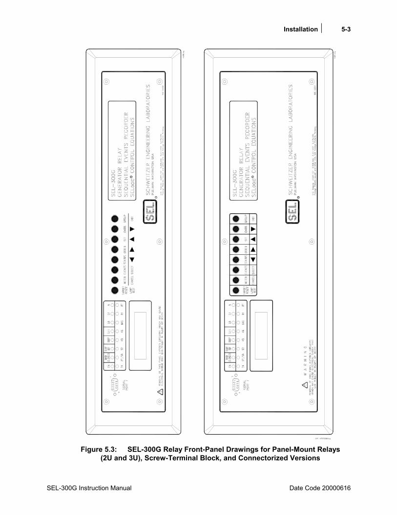
Installation 5-3
SEL-300G Instruction Manual Date Code 20000616
Figure 5.3: SEL-300G Relay Front-Panel Drawings for Panel-Mount Relays
(2U and 3U), Screw-Terminal Block, and Connectorized Versions
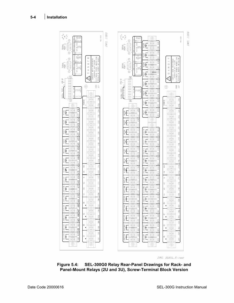
5-4 Installation
Date Code 20000616 SEL-300G Instruction Manual
Figure 5.4: SEL-300G0 Relay Rear-Panel Drawings for Rack- and
Panel-Mount Relays (2U and 3U), Screw-Terminal Block Version
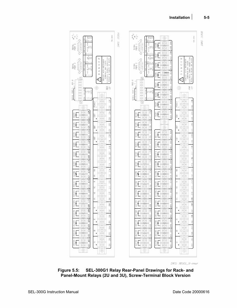
Installation 5-5
SEL-300G Instruction Manual Date Code 20000616
Figure 5.5: SEL-300G1 Relay Rear-Panel Drawings for Rack- and
Panel-Mount Relays (2U and 3U), Screw-Terminal Block Version
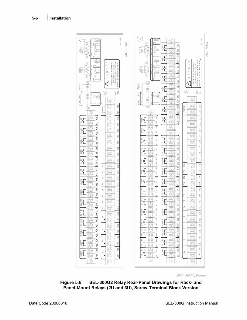
5-6 Installation
Date Code 20000616 SEL-300G Instruction Manual
Figure 5.6: SEL-300G2 Relay Rear-Panel Drawings for Rack- and
Panel-Mount Relays (2U and 3U), Screw-Terminal Block Version
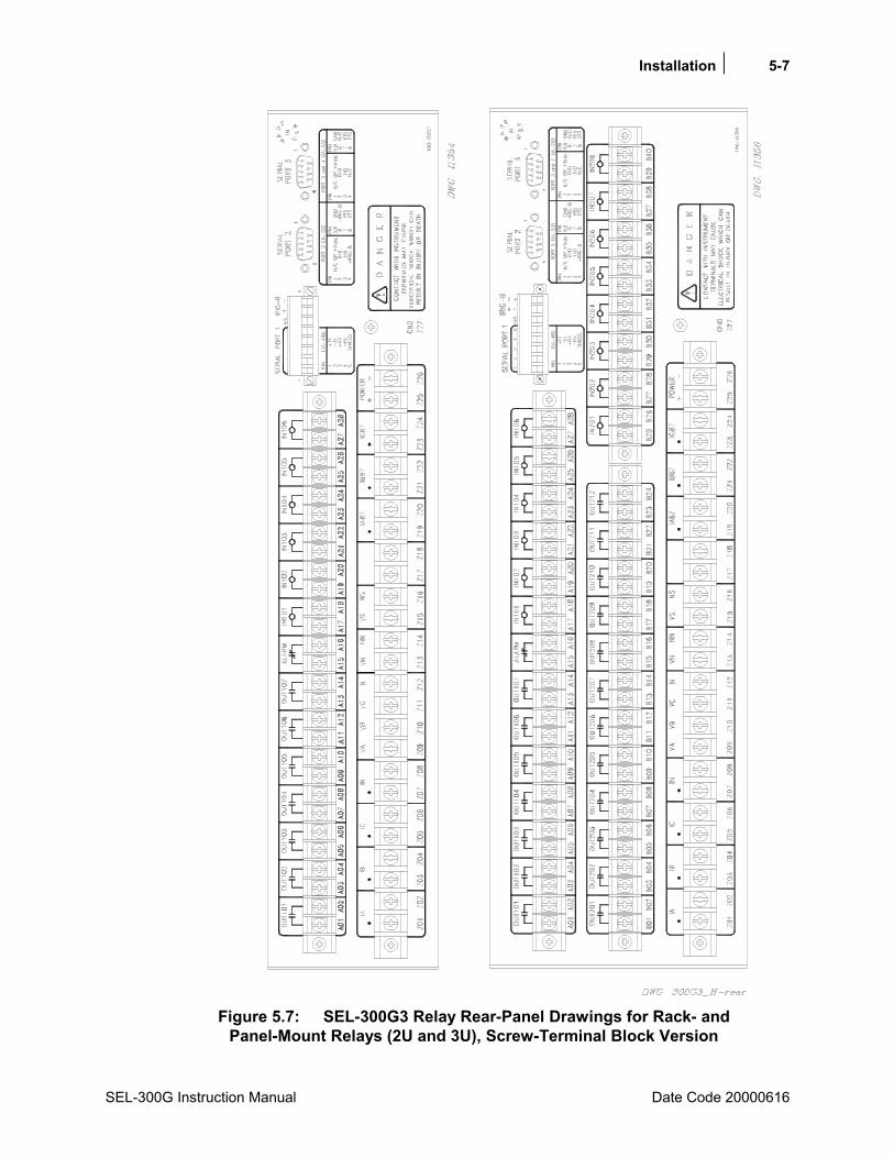
Installation 5-7
SEL-300G Instruction Manual Date Code 20000616
Figure 5.7: SEL-300G3 Relay Rear-Panel Drawings for Rack- and
Panel-Mount Relays (2U and 3U), Screw-Terminal Block Version
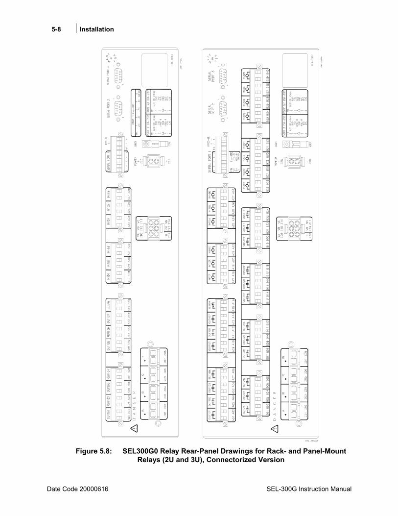
5-8 Installation
Date Code 20000616 SEL-300G Instruction Manual
Figure 5.8: SEL300G0 Relay Rear-Panel Drawings for Rack- and Panel-Mount
Relays (2U and 3U), Connectorized Version
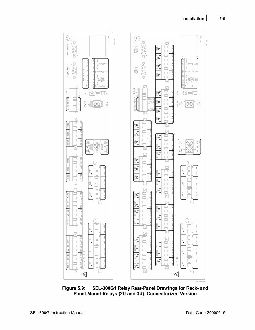
Installation 5-9
SEL-300G Instruction Manual Date Code 20000616
Figure 5.9: SEL-300G1 Relay Rear-Panel Drawings for Rack- and
Panel-Mount Relays (2U and 3U), Connectorized Version

5-10 Installation
Date Code 20000616 SEL-300G Instruction Manual
Figure 5.10: SEL-300G2 Relay Rear-Panel Drawings for Rack- and
Panel-Mount Relays (2U and 3U), Connectorized Version

Installation 5-11
SEL-300G Instruction Manual Date Code 20000616
Figure 5.11: SEL-300G3 Relay Rear-Panel Drawings for Rack- and
Panel-Mount Relays (2U and 3U), Connectorized Version
5-12 Installation
Date Code 20000616 SEL-300G Instruction Manual
MAKING REAR-PANEL CONNECTIONS Refer to Figure 5.13 through Figure 5.23 for wiring examples of typical applications.
Guard against accidental contact with rear terminals by using approved enclosures or any of the following methods:
• Location in a room, vault, or similar enclosure that is accessible only to qualified persons.
• Suitable permanent, substantial partitions or screens which are arranged so only qualified persons will have access to the space within reach of the live parts. Any openings in partitions or screens shall be located and sized so persons are not likely to come in accidental contact with the live parts or bring conducting objects into contact with them.
• Location on a suitable balcony, gallery, or platform so elevated and arranged as to exclude unqualified persons.
• Elevation of 8 ft (2.44 m) or more above the floor or other working surface.
Required Equipment and General Connect Information
Models 0300G_W and 0300G_Y (Connectorized)
Tools: small slotted tip screwdriver, wire strippers
Parts: SEL-WA0300G_W or SEL-WA0300G_Y Wiring Harness
Wiring Harness
The SEL-WA0300G_W and SEL-WA0300G_Y Wiring Harnesses include all connectors necessary for relay installation. All connectors requiring special termination come prewired from the factory. Refer to the SEL-WA0300G_W, SEL-WA0300G_Y Model Option Table, which is available from the factory.
The SEL-WA0300G_W Wiring Harness includes the following connectors (not prewired):
• (2) 8-position female plug-in connectors for output contacts OUT101 through ALARM.
• (2) 6-position female plug-in connectors for optoisolated inputs IN101 through IN106.
• (1) 8-position female plug-in connector for EIA-485/IRIG-B Serial Port 1.
The SEL-WA0300G_Y Wiring Harness includes the following connectors (not prewired):
• (2) 8-position female plug-in connectors for output contacts OUT101 through ALARM.
• (2) 6-position female plug-in connectors for optoisolated inputs IN101 through IN106.
• (1) 8-position female plug-in connector for EIA-485/IRIG-B Serial Port 1.
• (4) 6-position female plug-in connectors for output contacts OUT201 through OUT212
• (2) 8-position female plug-in connectors for optoisolated inputs IN201 through IN208.

Installation 5-13
SEL-300G Instruction Manual Date Code 20000616
These connectors accept wire size AWG 24 to 12. Strip the wires 0.31 inches (8 mm) and install with a small slotted-tip screwdriver. Secure each connector to the relay chassis with the screws located on either end of the connector. The connectors are coded at the factory to prevent swapping connectors during installation. Refer to Figure 5.12 for the standard input/output connector coding.
Both wiring harnesses include the following prewired connectors for all Connectorized SEL-300G Relays:
• (1) CT shorting connector for current inputs IA, IB, IC, and IN.
• (1) connector for voltage inputs VA, VB, VC, and VN.
• (1) connector for POWER inputs (+ and -).
• (1) spade connector for GROUND connection (chassis ground).
In addition, the wiring harness package also contains the following prewired connectors for specific models:
• (1) CT shorting connector for current inputs IA87, IB87, and IC87 (SEL-0300G1 and SEL-0300G3).
• (1) connector for voltage input VS (SEL-0300G2 and SEL-0300G3).
These prewired connectors (and the serial port connector) are unique and may only be installed in one orientation.
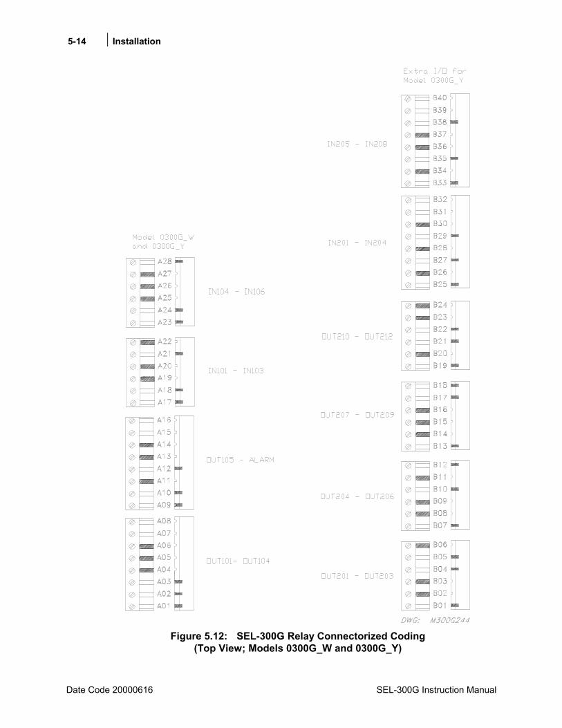
5-14 Installation
Date Code 20000616 SEL-300G Instruction Manual
Figure 5.12: SEL-300G Relay Connectorized Coding
(Top View; Models 0300G_W and 0300G_Y)
Installation 5-15
SEL-300G Instruction Manual Date Code 20000616
Models 0300G_0 and 000G_1 (screw-terminal blocks)
Tools: Phillips or slotted-tip screwdriver.
Parts: All screws are size #6-32. Locking screws can be requested from the factory.
Chassis Ground
Models 0300G_W and 000G_Y
Ground the relay chassis at terminal Z27 with the spade connector provided in the previously discussed wiring harness (tab size 0.250 inches x 0.032 inches). If the tab on the chassis is removed, the chassis ground connection can be made with the size #6-32 screw.
Models 0300G_0 and 0300G_1
Ground the relay chassis at terminal Z27.
Power Supply
Models 0300G_W and 0300G_Y
The power supply wiring harness includes a 2-position connector and factory-installed wire. Note the polarity indicators on terminals Z25 (+) and Z26 (-). Control power passes through these terminals to a fuse and to the switching power supply. The control power circuitry is isolated from the relay chassis ground.
Plug the power supply connector into terminals Z25 and Z26. The connector locks in place upon insertion.
Refer to Section 1: Introduction and Specifications for power supply ratings. The relay power supply rating is listed on the serial number sticker on the relay rear panel.
Models 0300G_0 and 000G_1
Connect control voltage to the POWER terminals. Note the polarity indicators on terminals Z25 (+) and Z26 (-). Control power passes through these terminals to a fuse and to the switching power supply. The control power circuitry is isolated from the relay chassis ground.
Refer to Section 1: Introduction and Specifications for power supply ratings. The relay power supply rating is listed on the serial number sticker on the relay rear panel.
Output Contacts
Models 0300G_0H, 0300G_03, 0300G_WH, and 0300G_W3
Models 0300G_0H, 0300G_03, 0300G_WH, and 0300G_W3 can be ordered with standard output contacts only. Refer to General Specifications in Section 1: Introduction and Specifications for output contact ratings.

5-16 Installation
Date Code 20000616 SEL-300G Instruction Manual
Standard output contacts are not polarity dependent.
Models 0300G_1H, 0300G_13, 0300G_YH, and 0300G_Y3
Models 0300G_1H, 0300G_13, 0300G_YH, and 0300G_Y3 have output contacts on the:
main board OUT101 through ALARM (ordered as standard output contacts only)
extra I/O board OUT201 through OUT212 [ordered as standard or high current interrupting output contacts (all of one type or the other)]
Refer to General Specifications in Section 1: Introduction and Specifications for output contact ratings. To determine the type of output contacts on the extra I/O board of your Model 0300G_1 and 0300G_Y relays, refer to the part number on the serial number sticker on the relay rear panel.
Standard Output Contacts
Model 0300G_1 or 0300G_Y part numbers with a numeral "2" in bold below (sample part number) indicate standard output contacts on the extra I/O board (OUT201 through OUT212):
0 3 0 0 G _ Y _ _ _ _ 2 X _ X (Connectorized models)
0 3 0 0 G _ 1 _ _ _ _ 2 X _ X (screw-terminal block models)
Standard Output contacts are not polarity dependent.
High Current Interrupting Output Contacts
Model 0300G_1 part numbers with a numeral "6" in bold below (sample part number) indicate high current interrupting output contacts on the extra I/O board (OUT201 through OUT212):
0 3 0 0 G _ Y _ _ _ _ 6 X _ X (Connectorized models)
0 3 0 0 G _ 1 _ _ _ _ 6 X _ X (screw-terminal block models)
High current interrupting output contacts are polarity dependent. When high current interrupting output contacts are ordered, the positive polarity terminal is indicated with a "+" polarity marking above even-numbered terminals B02, B04, B06, . . ., B24. The extra I/O board of the relays shown in Figure 5.4 through Figure 5.11 do not show these "+" polarity markings because these drawings show the rear panel for an extra I/O board with standard output contacts.
As an example, consider the connection of terminals B01 and B02 (high current interrupting output contact OUT201) in a circuit:
Terminal B02 (+) has to be at a higher voltage potential than terminal B01 in the circuit.
The same holds true for output contacts OUT202 through OUT212 (if they are also high current interrupting output contacts).
Note: Do not use the high current interrupting output contacts to switch ac control signals.
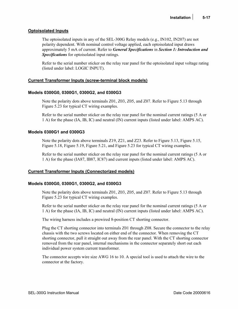
Installation 5-17
SEL-300G Instruction Manual Date Code 20000616
Optoisolated Inputs
The optoisolated inputs in any of the SEL-300G Relay models (e.g., IN102, IN207) are not polarity dependent. With nominal control voltage applied, each optoisolated input draws approximately 5 mA of current. Refer to General Specifications in Section 1: Introduction and Specifications for optoisolated input ratings.
Refer to the serial number sticker on the relay rear panel for the optoisolated input voltage rating (listed under label: LOGIC INPUT).
Current Transformer Inputs (screw-terminal block models)
Models 0300G0, 0300G1, 0300G2, and 0300G3
Note the polarity dots above terminals Z01, Z03, Z05, and Z07. Refer to Figure 5.13 through Figure 5.23 for typical CT wiring examples.
Refer to the serial number sticker on the relay rear panel for the nominal current ratings (5 A or 1 A) for the phase (IA, IB, IC) and neutral (IN) current inputs (listed under label: AMPS AC).
Models 0300G1 and 0300G3
Note the polarity dots above terminals Z19, Z21, and Z23. Refer to Figure 5.13, Figure 5.15, Figure 5.18, Figure 5.19, Figure 5.21, and Figure 5.23 for typical CT wiring examples.
Refer to the serial number sticker on the relay rear panel for the nominal current ratings (5 A or 1 A) for the phase (IA87, IB87, IC87) and current inputs (listed under label: AMPS AC).
Current Transformer Inputs (Connectorized models)
Models 0300G0, 0300G1, 0300G2, and 0300G3
Note the polarity dots above terminals Z01, Z03, Z05, and Z07. Refer to Figure 5.13 through Figure 5.23 for typical CT wiring examples.
Refer to the serial number sticker on the relay rear panel for the nominal current ratings (5 A or 1 A) for the phase (IA, IB, IC) and neutral (IN) current inputs (listed under label: AMPS AC).
The wiring harness includes a prewired 8-position CT shorting connector.
Plug the CT shorting connector into terminals Z01 through Z08. Secure the connector to the relay chassis with the two screws located on either end of the connector. When removing the CT shorting connector, pull it straight out away from the rear panel. With the CT shorting connector removed from the rear panel, internal mechanisms in the connector separately short out each individual power system current transformer.
The connector accepts wire size AWG 16 to 10. A special tool is used to attach the wire to the connector at the factory.

5-18 Installation
Date Code 20000616 SEL-300G Instruction Manual
Models 0300G1 and 0300G3
Note the polarity dots above terminals Z19, Z21, and Z23. Refer to Figure 5.13, Figure 5.15, Figure 5.18, Figure 5.19, Figure 5.21, and Figure 5.23 for typical CT wiring examples.
Refer to the serial number sticker on the relay rear panel for the nominal current ratings (5 A or 1 A) for the phase (IA87, IB87, IC87) and current inputs (listed under label: AMPS AC).
The wiring harness includes a prewired 6-position CT shorting connector.
Plug the CT shorting connector into terminals Z19 through Z24. Secure the connector to the relay chassis with the two screws located on either end of the connector. When removing the CT shorting connector, pull it straight out away from the rear panel. With the CT shorting connector removed from the rear panel, internal mechanisms in the connector separately short out each individual power system current transformer.
The connectors accept wire size AWG 16 to 10. A special tool is used to attach the wire to the connector at the factory.
Potential Transformer Inputs
Any of the phase voltage inputs can be connected to voltages up to 200 V continuous. The neutral voltage input VN NN can be connected to voltages up to 300 V continuous. The synch voltage input VS NS can be connected to voltages up to 200 V continuous. Figure 5.13 through Figure 5.23 show examples of typical voltage connections. Generator frequency is determined from the voltage connected to terminals VA N. System frequency (for the optional synch-check element) is determined from the voltage connected to the terminals VS NS.
Serial Ports
Refer to Table 10.1 for information on the serial ports available on the different SEL-300G Relay models.
Serial Port 1 on all the SEL-300G Relay models is an EIA-485 port (4-wire). The Serial Port 1 Connectorized connector accepts wire size AWG 24 to 12. Strip the wires 0.31 inches (8 mm) and install with a small slotted-tip screwdriver. Serial Port 1 connector has extra positions for IRIG-B time-code signal input (see Table 10.3; see following discussion on IRIG-B time-code input).
All EIA-232 ports accept 9-pin D-subminiature male connectors. Port 2 on all the SEL-300G Relay models includes the IRIG-B time-code signal input (see Table 10.2; see following discussion on IRIG-B time-code input).
The pin definitions for all the ports are given on the relay rear panel and detailed in Table 10.2 through Table 10.4 in Section 10: Serial Port Communications and Commands.
Refer to for a list of cables available from SEL for various communication applications. Refer to Section 10: Serial Port Communications and Commands for detailed cable diagrams for selected cables (cable diagrams precede Table 10.4).
Note: Listing of devices not manufactured by SEL in is for the convenience of our customers. SEL does not specifically endorse or recommend such products, nor does SEL guarantee

Installation 5-19
SEL-300G Instruction Manual Date Code 20001212
proper operation of those products or the correctness of connections over which SEL has no control.
For example, to connect any EIA-232 port to the 9-pin male connector on a laptop computer, order cable number C234A and specify the length needed (standard length is 8 feet). To connect the SEL-300G Relay Port 2 to the SEL-2020/SEL-2030 Communications Processor that supplies the communication link and the IRIG-B time synchronization signal, order cable number C273A. For connecting devices at distances over 100 feet, SEL offers fiber-optic transceivers. The SEL-2800 family of transceivers provides fiber-optic links between devices for electrical isolation and long distance signal transmission. Contact SEL for further information on these products.
Table 5.1: Communication Cables to Connect the SEL-300G Relay to Other Devices
SEL-300G EIA-232 Serial Ports
Connect to Device (gender refers to the device)
SEL Cable #
all EIA-232 ports PC, 25-Pin Male (DTE2) C227A
all EIA-232 ports Laptop PC, 9-Pin Male (DTE2) C234A
all EIA-232 ports SEL-2020 without IRIG-B C272A
2 SEL-2020 with IRIG-B C273A
all EIA-232 ports SEL-PRTU C231
2 SEL-IDM, Ports 2 through 11 C254 + C257
21 31
Telenetics Modem, 5 Vdc Powered C220*
all EIA-232 ports Standard Modem, 25-Pin Female (DCE3) C222
all EIA-232 ports RFL-9660 C245A
All EIA-232 ports (with SEL-2800
transceiver)
SEL-2600 RTD Module C801FD
1A corresponding main board jumper must be installed to power the Telenetics Modem with +5 Vdc (0.5 A limit) from the SEL-300G Relay. See Figure 5.25 and Table 5.7.
2Data terminal equipment 3Data circuit-terminating equipment
IRIG-B Time-Code Input
The SEL-300G Relay accepts a demodulated IRIG-B time signal to synchronize the relay internal clock with some external source. The demodulated IRIG-B time signal can come via the SEL-2020 Communications Processor or the SEL-IDM listed in Table 5.3. A demodulated IRIG-B time code can be input into Serial Port 2 on any of the SEL-300G Relay models (see Table 10.2). This is handled adeptly by connecting Serial Port 2 of the SEL-300G Relay to an SEL-2020 with Cable C273A. Port 2 also can be connected to the SEL-IDM with Cable 254 plus Cable 257.

5-20 Installation
Date Code 20000616 SEL-300G Instruction Manual
A demodulated IRIG-B time code can be input into the connector for Serial Port 1 (see Table 10.3). If demodulated IRIG-B time code is input into this connector, it should not be input into Serial Port 2 and vice versa.
EXAMPLE AC AND DC CONNECTION DIAGRAMS
DWG: M300G087
GeneratorPhase-Input
Current Transformers87-Input
Current TransformersA
B
C
C
B
A
Z14
Z13
Z08
Z07
Z06
Z05
Z04
Z03
Z02
Z01
Z24
Z23
Z22
Z21
Z20
Z19
IC87
VN IN IC IB IA IB87
IA87
VAVC VB
Z09
Z10
Z11
Z12N
Figure 5.13: SEL-300G1 Relay AC Connection Example High-Impedance
Grounded Generator With Current Differential Protection
DWG: M300G088
GeneratorPhase-Input
Current TransformersA
B
C
C
B
AZ14
Z13
Z08
Z07
Z06
Z05
Z04
Z03
Z02
Z01
Z12
Z11
Z10
Z09
VN IN IC IB IA VC VAVBN
Figure 5.14: SEL-300G0 Relay AC Connection Example High-Impedance
Grounded Generator Without Current Differential Protection
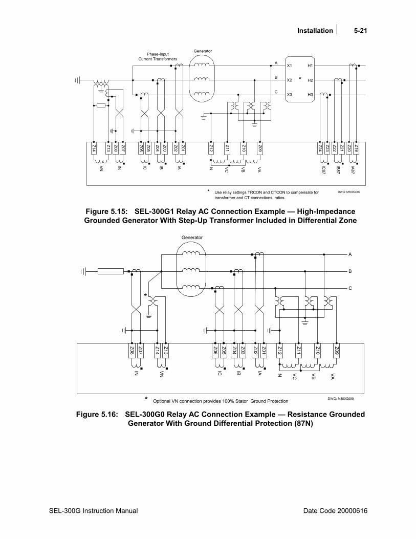
Installation 5-21
SEL-300G Instruction Manual Date Code 20000616
Z19
Z22
Z21
Z24
Z23
Z20
DWG: M300G089
GeneratorPhase-Input
Current Transformers
Z14
Z13
Z08
Z07
Z06
Z05
Z04
Z03
Z02
Z01
VN IN IC IB IA
X1
X2
X3 H3
H2
H1
*
IA87
IB87
IC87
* Use relay settings TRCON and CTCON to compensate fortransformer and CT connections, ratios.
A
B
C
Z12
Z11
Z10
Z09
VC VAVBN
Figure 5.15: SEL-300G1 Relay AC Connection Example High-Impedance Grounded Generator With Step-Up Transformer Included in Differential Zone
Z05
Z04
Z03
Z02
Z01
Z06
DWG: M300G090
Generator
Z08
Z07
Z12
Z11
Z10
Z09
IN VC VAVB
IC IB IA
*
Z14
Z13VN
* Optional VN connection provides 100% Stator Ground Protection
A
B
C
N
Figure 5.16: SEL-300G0 Relay AC Connection Example Resistance Grounded
Generator With Ground Differential Protection (87N)
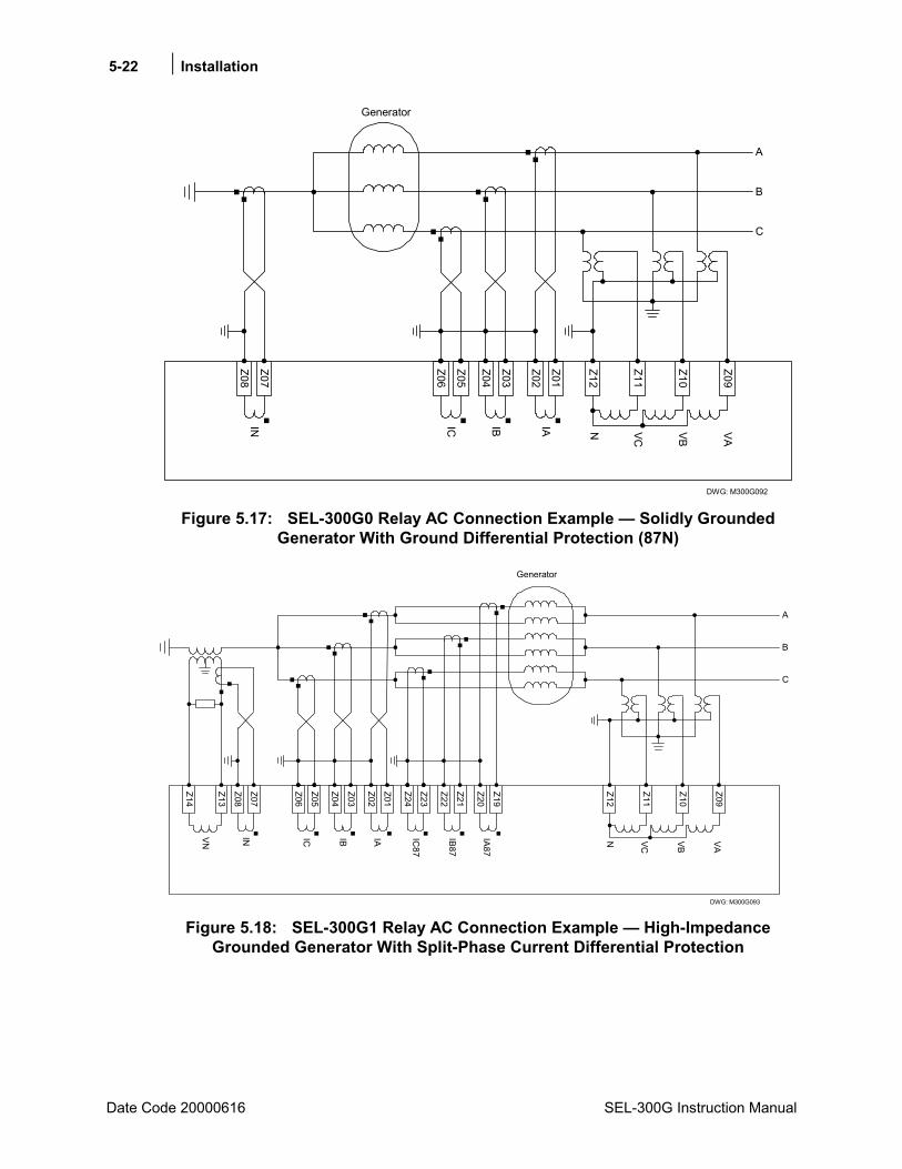
5-22 Installation
Date Code 20000616 SEL-300G Instruction Manual
Z05
Z04
Z03
Z02
Z01
Z06
DWG: M300G092
Generator
Z08
Z07
Z12
Z11
Z10
Z09
IN VC VAVB
IC IB IA
A
B
C
N
Figure 5.17: SEL-300G0 Relay AC Connection Example Solidly Grounded
Generator With Ground Differential Protection (87N)
Z05
Z04
Z03
Z02
Z01
Z06
DWG: M300G093
Generator
IC IB IA
Z23
Z24IC
87
Z22
Z21IB87
Z20
Z19IA87
A
B
C
Z14
Z13
Z08
Z07
VN IN
Z12
Z11
Z10
Z09
VC VAVBN
Figure 5.18: SEL-300G1 Relay AC Connection Example High-Impedance
Grounded Generator With Split-Phase Current Differential Protection
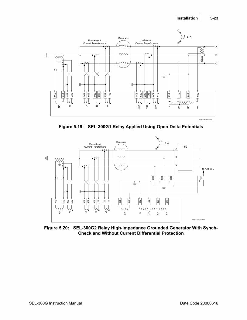
Installation 5-23
SEL-300G Instruction Manual Date Code 20000616
DWG: M300G204
GeneratorPhase-Input
Current Transformers87-Input
Current Transformers
C
B
A
Z14
Z13
Z08
Z07
Z06
Z05
Z04
Z03
Z02
Z01
Z24
Z23
Z22
Z21
Z20
Z19
IC87
VN IN IC IB IA IB87
IA87
VAVC VB
A
B
C
Z09
Z10
Z11
Z12N
Figure 5.19: SEL-300G1 Relay Applied Using Open-Delta Potentials
GeneratorPhase-Input
Current TransformersA
B
C
C
B
A
52
to A, B, or C
DWG: M300G202
Z14
Z13
Z08
Z07
Z06
Z05
Z04
Z03
Z02
Z01
VN IN IC IB IA
Z16
Z15
VS
Z12
Z11
Z10
Z09
VC VAVBN
Figure 5.20: SEL-300G2 Relay High-Impedance Grounded Generator With Synch-
Check and Without Current Differential Protection

5-24 Installation
Date Code 20000616 SEL-300G Instruction Manual
Z12
Z11
Z10
Z09
VC VAVBN
Z05
Z04
Z03
Z02
Z01
Z06
DWG: M300G206
Generator
IC IB IA
Z23
Z24IC
87
Z22
Z21IB87
Z20
Z19IA87
A
B
C
Z14
Z13
Z08
Z07
VN IN
Window CT
Figure 5.21: SEL-300G1 Relay High-Impedance Grounded Generator With Split-
Phase, Self-Balancing Differential Protection
Z05
Z04
Z03
Z02
Z01
Z06
DWG: M300G205
Generator
Z08
Z07
Z12
Z11
Z10
Z09
IN VC VAVB
IC IB IA
A
B
C
52
SYNCP=VBC
Z16
Z15
VSN
Figure 5.22: SEL-300G2 Relay Solidly Grounded Generator With Ground
Differential (87N) and Synch-Check
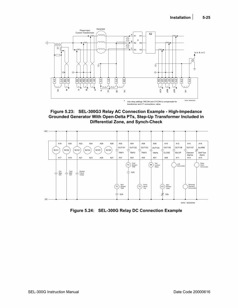
Installation 5-25
SEL-300G Instruction Manual Date Code 20000616
Z19
Z22
Z21
Z24
Z23
Z20
DWG: M300G203
GeneratorPhase-Input
Current Transformers
Z14
Z13
Z08
Z07
Z06
Z05Z04
Z03
Z02
Z01
VN IN IC IB IA VAVC VB
X1
X2
X3 H3
H2
H1
*
IA87
IB87
IC87
* Use relay settings TRCON and CTCON to compensate fortransformer and CT connections, ratios.
N
A
B
C
to A, B, or C
Z16
Z15
VS
52
Z09
Z10
Z11
Z12
Figure 5.23: SEL-300G3 Relay AC Connection Example - High-Impedance
Grounded Generator With Open-Delta PTs, Step-Up Transformer Included in Differential Zone, and Synch-Check
+DC
-DC
IN101 IN102 IN103 IN104 IN105 IN106OUT101
TRIP1
OUT102
TRIP2
OUT103
TRIP3
OUT104
TRIP4
OUT105
CLOSE
OUT106
60LOP
OUT107
ElementAlarms
ALARM
Self-TestAlarm
TC
TC
TC
86
CC
GenMain52A
FieldBKR52A
BreakerFailureInitiate
MainBreakerTRIP
52A
52A
FieldBreakerTRIP
PrimeMoverTrip
GenLockoutRelay
MainBreakerClose
52b
LOPAnnunciator
AbnormalOperationAnnunciator
RelayAlarmAnnunciator
A18 A20 A22 A24 A26 A28 A02 A04 A06 A08 A10 A12 A14 A16
A17 A19 A21 A23 A25 A27 A01 A03 A05 A07 A09 A11 A13 A15
DWG: M300G094 Figure 5.24: SEL-300G Relay DC Connection Example
5-26 Installation
Date Code 20000616 SEL-300G Instruction Manual
CIRCUIT BOARD JUMPERS AND BATTERY
Accessing the Relay Main Board (All Models) and Extra I/O Board (Models 0300G_1 and 0300G_Y)
To change circuit board jumpers or replace the clock battery on the relay main board (or change output contact jumpers on the extra I/O board), refer to Figure 5.25 and Figure 5.26 and take the following steps:
1. Deenergize the relay. On Connectorized versions this can be accomplished easily by removing the connector at rear-panel terminals Z25 and Z26.
2. Remove any cables connected to serial ports on the front and rear panels.
3. Loosen the six front-panel screws (they remain attached to the front panel), and remove the relay front panel.
CAUTION!
The relay contains devices sensitive to electrostatic discharge (ESD). When working on the relay with front or top cover removed, work surfaces and personnel must be properly grounded or equipment damage may result.
4. Identify which drawout board needs to be changed. All SEL-300G Relay models have a main board in the top guides, and Models 0300G_1 and 0300G_Y have an extra I/O board below the main board. Each board corresponds to a row of rear-panel screw-terminal blocks.
5. On Connectorized versions, remove the rear-panel connectors that correspond to the circuit board you wish to remove by loosening the screws on either end of each connector. Removal of the extra I/O board also requires removal of the main board (because the LCD on the main board is in the way).
6. On screw-terminal block models, disconnect the ribbon cables from the board(s). Grasp the drawout assembly of the board, and pull the assembly from the relay chassis. In Models 0300G_1 and 0300G_Y, the extra I/O board directly below the main board requires removal of the main board first (because the LCD on the main board is in the way).
7. Locate the jumper(s) or battery to be changed (refer to Figure 5.25 and Figure 5.26 ). Change the jumper position(s). Note that the output contact jumpers are soldered in place.
8. Slide the drawout assemblies into the relay chassis (main board last). Reconnect the ribbon cables. Replace the relay front panel and reenergize the relay. On Connectorized versions, replace the power connector at rear-panel terminals Z25 and Z26.
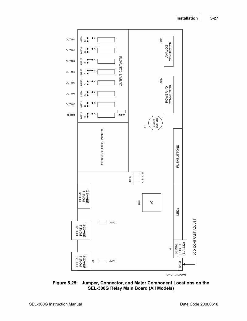
Installation 5-27
SEL-300G Instruction Manual Date Code 20000616
ALARM
OUT106
OUT105
OUT104
OUT107
OUT103
OUT102
OUT101
OPT
OIS
OLA
TED
IN
PUTS
OU
TPU
T C
ON
TAC
TS
A
BJM
P29
DWG: M300G096
A
BJM
P28
A
BJM
P27
A
BJM
P26
A
BJM
P25
A
BJM
P24
A
BJM
P22
A
BJM
P21
JMP23
SER
IAL
POR
T 1
(EIA
-485
)
SER
IAL
POR
T 2
(EIA
-232
)
SER
IAL
POR
T 3
(EIA
-232
)
JMP1J1
JMP2
JMP6
AB
CD
µCU46
SER
IAL
POR
T F
(EIA
-232
)R
131
LED
sPU
SHBU
TTO
NS
POW
ER-I/
OC
ON
NEC
TOR
ANAL
OG
CO
NN
ECTO
R
LCD
CO
NTR
AST
ADJU
ST
J10
B1 CLO
CK
BATT
ERY
J8/J
9
J7
Figure 5.25: Jumper, Connector, and Major Component Locations on the
SEL-300G Relay Main Board (All Models)
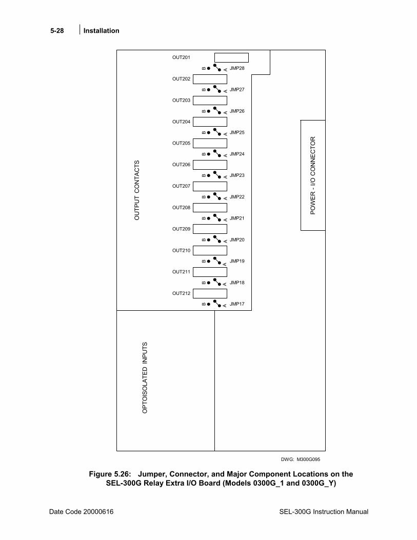
5-28 Installation
Date Code 20000616 SEL-300G Instruction Manual
AB
AA
AA
AB
AB
OUT212
OUT211
OUT210
OUT209
OUT207
OUT206
OUT205
JMP17
JMP19
JMP18BB
BB
A
OUT208B
AB
OUT204
AB
OUT203
AB
OUT202
OPT
OIS
OLA
TED
IN
PUTS
OU
TPU
T C
ON
TAC
TS
AB
POW
ER -
I/O C
ON
NEC
TOR
JMP20
JMP21
JMP22
JMP23
JMP24
JMP25
JMP26
JMP27
JMP28
OUT201
DWG: M300G095 Figure 5.26: Jumper, Connector, and Major Component Locations on the
SEL-300G Relay Extra I/O Board (Models 0300G_1 and 0300G_Y)

Installation 5-29
SEL-300G Instruction Manual Date Code 20000616
Output Contact Jumpers
Table 5.2 shows the correspondence between output contact jumpers and the output contacts they control. The referenced figures show the exact location and correspondence. With a jumper in the A position, the corresponding output contact is an a type output contact. An a type output contact is open when the output contact coil is deenergized and closed when the output contact coil is energized. With a jumper in the B position, the corresponding output contact is a b type output contact. A b type output contact is closed when the output contact coil is deenergized and open when the output contact coil is energized. These jumpers are soldered in place.
In the figures referenced in Table 5.2, note that the ALARM output contacts are b type output contacts and the other output contacts are all a type output contacts. This is how these jumpers are configured in a standard relay shipment. Refer to corresponding Figure 4.16 and Figure 4.17 for examples of output contact operation for different output contact types.
Table 5.2: Output Contact Jumpers and Corresponding Output Contacts
SEL-300G Relay Model Number
Output Contact Jumpers
Corresponding Output Contacts
Reference Figures
All Models JMP21JMP29 (but not JMP23)
ALARMOUT101 Figure 5.25
0300G_1 and 0300G_Y JMP17JMP28 OUT212OUT201 Figure 5.26
Extra Alarm Output Contact Control Jumper
All the SEL-300G Relay models have dedicated alarm output contacts (labeled ALARM see Figure 5.4 through Figure 5.11). Often more than one alarm output contact is needed for such applications as local or remote annunciation, backup schemes, etc. An extra alarm output contact can be had for all the SEL-300G Relay models without the addition of any external hardware.
The output contact next to the dedicated ALARM output contact can be converted to operate as an extra alarm output contact by moving a jumper on the main board (see Table 5.3).
Table 5.3: Extra Alarm Output Contacts and Corresponding Controlling Jumpers
SEL-300G Relay Model Number
Extra Alarm Output Contact
Controlling Jumper
Reference Figures
All Models OUT107 JMP23 Figure 5.25, Figure 4.16
The position of the jumper controls the operation of the output contact OUT107. With the jumper in one position, the output contact operates regularly. With the jumper in the other position, the output contact is driven by the same signal that operates the dedicated ALARM output contact (see Table 5.4).
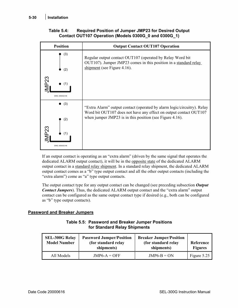
5-30 Installation
Date Code 20000616 SEL-300G Instruction Manual
Table 5.4: Required Position of Jumper JMP23 for Desired Output Contact OUT107 Operation (Models 0300G_0 and 0300G_1)
Position Output Contact OUT107 Operation
DWG: M300G146
(1)
(2)
(3)
JMP2
3
Regular output contact OUT107 (operated by Relay Word bit OUT107). Jumper JMP23 comes in this position in a standard relay shipment (see Figure 4.16).
DWG: M300G146
(1)
(2)
(3)
JMP2
3
Extra Alarm output contact (operated by alarm logic/circuitry). Relay Word bit OUT107 does not have any effect on output contact OUT107 when jumper JMP23 is in this position (see Figure 4.16).
If an output contact is operating as an extra alarm (driven by the same signal that operates the dedicated ALARM output contact), it will be in the opposite state of the dedicated ALARM output contact in a standard relay shipment. In a standard relay shipment, the dedicated ALARM output contact comes as a b type output contact and all the other output contacts (including the extra alarm) come as a type output contacts.
The output contact type for any output contact can be changed (see preceding subsection Output Contact Jumpers). Thus, the dedicated ALARM output contact and the extra alarm output contact can be configured as the same output contact type if desired (e.g., both can be configured as b type output contacts).
Password and Breaker Jumpers
Table 5.5: Password and Breaker Jumper Positions for Standard Relay Shipments
SEL-300G Relay Model Number
Password Jumper/Position(for standard relay
shipments)
Breaker Jumper/Position (for standard relay
shipments)
Reference
Figures
All Models JMP6-A = OFF JMP6-B = ON Figure 5.25

Installation 5-31
SEL-300G Instruction Manual Date Code 20001212
Table 5.6: Password and Breaker Jumper Operation
Jumper Type Jumper Position Function
Password ON (in place)
disable password protection1 for serial ports and front panel
OFF (removed/not in place)
enable password protection1 for serial ports and front panel
Breaker ON (in place)
enable serial port commands OPEN, CLOSE, and PULSE2
OFF (removed/not in place)
disable serial port commands OPEN, CLOSE, and PULSE2
1View or set the passwords with the PASSWORD command (see Section 10: Serial Port Communications and Commands).
2The OPEN, CLOSE, and PULSE commands are used primarily to assert output contacts for circuit breaker control or testing purposes (see Section 10: Serial Port Communications and Commands).
Note that jumper JMP6 in Figure 5.25 has C and D jumper positions, too. Jumpers should not be installed in the C and D jumper positions.
EIA-232 Serial Port Voltage Jumpers
The jumpers listed in Table 5.7 connect or disconnect +5 Vdc to Pin 1 on the corresponding EIA-232 serial ports. The +5 Vdc is rated at 0.5 A maximum for each port. See Table 10.2 in Section 10: Serial Port Communications and Commands for EIA-232 serial port pin functions.
In a standard relay shipment, the jumpers are OFF (removed/not in place) so that the +5 Vdc is not connected to Pin 1 on the corresponding EIA-232 serial ports. Put the jumpers ON (in place) so that the +5 Vdc is connected to Pin 1 on the corresponding EIA-232 serial ports.
Condition of Acceptability for North American Product Safety Compliance
To meet product safety compliance for end-use applications in North America, use an external fuse rated 3 A or less in-line with the +5 Vdc source on Pin 1. SEL fiber-optic transceivers include a fuse that meets this requirement.
Table 5.7: EIA-232 Serial Port Voltage Jumper Positions for Standard Relay Shipments
SEL-300G Relay Model Number
EIA-232 Serial Port 2 (rear panel)
EIA-232 Serial Port 3 (rear panel)
Reference
Figure
All Models JMP2 = OFF JMP1 = OFF Figure 5.25

5-32 Installation
Date Code 20001212 SEL-300G Instruction Manual
Clock Battery
Refer to Figure 5.25 for clock battery location (front of main board). A lithium battery powers the relay clock (date and time) if the external dc source is lost or removed. The battery is a 3 V lithium coin cell. At room temperature (25°C), the battery will operate nominally for 10 years at rated load.
If the dc source is lost or disconnected, the battery discharges to power the clock. When the relay is powered from an external source, the battery only experiences a low self-discharge rate. Thus, battery life can extend well beyond the nominal 10 years because the battery rarely has to discharge after the relay is installed. The battery cannot be recharged.
CAUTION!
There is danger of explosion if the battery is incorrectly replaced. Replace only with Ray-O-Vac® no. BR2335 or equivalent recommended by manufacturer. Dispose of used batteries according to the manufacturers instructions.
If the relay does not maintain the date and time after power loss, replace the battery. Follow the instructions in the previous subsection Accessing the Relay Main Board (All Models) and Extra I/O Board (Models 0300G_1 and 0300G_Y) to remove the relay main board. Remove the battery from beneath the clip and install a new one. The positive side (+) of the battery faces up. Reassemble the relay as described in Accessing the Relay Main Board (All Models) and Extra I/O Board (Models 0300G_1 and 0300G_Y). Set the relay date and time via serial communications port or front panel (see Section 10: Serial Port Communications and Commands or Section 9: Front-Panel Operation, respectively).
SEL-300G Instruction Manual Date Code 20010615
TABLE OF CONTENTS
SECTION 6: ENTER RELAY SETTINGS............................................6-1
Introduction ...................................................................................................................................6-1 Settings Changes via the Serial Port .............................................................................................6-1
Introduction ...........................................................................................................................6-1 Communication Setup ...........................................................................................................6-1 Terminal Emulation...............................................................................................................6-2 Establish Communication .....................................................................................................6-2 Setting Entry..........................................................................................................................6-2 Setting Entry Error Messages................................................................................................6-3
Modify Settings via the Front Panel .............................................................................................6-6 Settings Sheets ..............................................................................................................................6-9
TABLES Table 6.1: Serial Port SET Commands .....................................................................................................6-1 Table 6.2: SET Command Editing Keystrokes .........................................................................................6-3 Table 6.3: Setting Interdependency Error Messages ................................................................................6-4
FIGURES Figure 6.1: Front-Panel SET Pushbutton Options Setting Sheets.............................................................6-8


Enter Relay Settings 6-1
SEL-300G Instruction Manual Date Code 20000616
SECTION 6: ENTER RELAY SETTINGS
INTRODUCTION Change or view settings with the SET and SHOWSET serial port commands and the front-panel SET pushbutton. Table 6.1 lists the serial port SET commands.
Table 6.1: Serial Port SET Commands
Command Settings Type Description
SET n Group Protection elements, timers, etc., for setting Groups 1 and 2.
SET G Global Battery and breaker monitors, optoisolated input debounce timers, etc.
SET R SER Sequential Events Recorder trigger conditions and ALIAS settings.
SET P n Port Serial port settings for Serial Port n (n = 1, 2, 3, or F).
View settings with the respective serial port SHOWSET commands (SHO, SHO G, SHO R, SHO P). See SHO Command (Show View Settings) in Section 10: Serial Port Communications and Commands.
SETTINGS CHANGES VIA THE SERIAL PORT
Introduction
All available relay settings may be viewed or modified using the relay serial ports, via the SET and SHOWSET commands described above. To view or modify relay settings through a serial port, you must connect a PC to the serial port, establish serial communication at the appropriate access level, then use the relay commands appropriate to the particular task. These steps are described in more detail below.
Communication Setup
Typically, it is easiest to connect the EIA-232 serial port of a PC to one of the relay EIA-232 serial ports directly using a metallic or fiber optic cable. Section 10: Serial Port Communications and Commands describes the cable necessary to make these connections. The SEL-5801 Cable Selector software is also helpful to determine the correct cabling for relay communications. This software is available free of charge from the factory or may be downloaded from our world wide web site at www.selinc.com.
6-2 Enter Relay Settings
Date Code 20000616 SEL-300G Instruction Manual
Terminal Emulation
As described in Section 10: Serial Port Communications and Commands, SEL relays respond to ASCII text commands entered on the relay serial port. PC terminal emulation packages such as Microsoft Windows® Terminal, Procomm Plus, SmartCOM, CROSSTALK®, and many other packages allow ASCII commands to be sent from the PC serial port and relay responses displayed.
Configure the terminal emulation package you select to operate the PC COM port (COM1, COM2, etc.) at the relay baud rate (factory default 2400 bd), using 8 data bits, 1 stop bit, no parity bit, and XON/XOFF flow control. Refer to the terminal emulation package documentation for assistance in making these PC communication port configuration settings.
Establish Communication
Note: In this manual, commands you type appear in bold/uppercase: SET. Computer keys you press appear in bold/uppercase/brackets: <ENTER>.
Prepare to enter relay settings by connecting the PC (equipped with serial port and terminal emulation software) to the relay serial port using the correct communication cable.
Apply power to the relay, turn on the PC, and start the terminal emulation software package.
If necessary, configure the terminal emulation software for communication with the relay (see above for basic guidelines; Section 10: Serial Port Communications and Commands contains additional details).
With the terminal emulation software active at the terminal screen, you should see an = prompt appear on the screen after you press the <ENTER> or <RETURN> key on the PC keyboard.
The = prompt is the indication that the relay is communicating at Access Level 0. Relay settings are entered at Access Level 2.
Setting Entry
See Section 10: Serial Port Communications and Commands for information on serial port communications and relay access levels. The SET commands in Table 6.1 operate at Access Level 2 (screen prompt: =>>).
When you issue the SET command, the relay presents a list of settings, one at a time. Enter a new setting, or press <ENTER> to accept the existing setting. Editing keystrokes are shown in Table 6.2.

Enter Relay Settings 6-3
SEL-300G Instruction Manual Date Code 20000616
Table 6.2: SET Command Editing Keystrokes
Press Key(s) Results
<ENTER> Retains setting and moves to the next setting.
^ <ENTER> Returns to previous setting.
< <ENTER> Returns to previous setting category.
> <ENTER> Moves to next setting category.
END<ENTER> Exits editing session, then prompts you to save the settings.
<CTRL> X Aborts editing session without saving changes.
The relay checks each entry to ensure that it is within the setting range. If it is not, an Out of Range message is generated, and the relay prompts for the setting again.
When all the settings are entered, the relay displays the new settings and prompts for approval to enable them. Answer Y<ENTER> to enable the new settings. If changes are made to Global, SER, or Port settings (see Table 6.1), the relay is disabled while it saves the new settings. If changes are made to the Group settings for the active setting group (see Table 6.1), the relay is disabled while it saves the new settings. The ALARM contact closes momentarily for b contact (opens for an a; see Figure 4.16), and the EN LED extinguishes while the relay is disabled. The relay is disabled for as long as 15 seconds.
If changes are made to the Group settings for the inactive setting group (see Table 6.1), the relay is not disabled while it saves the new settings. The ALARM contact closes momentarily for b contact (opens for an a; see Figure 4.16), but the EN LED remains on while the new settings are saved.
To change a specific setting, enter the command:
SET n m s TERSE
where n = G, R, or P (parameter n is not entered for the Group settings). m = group (1 or 2) or port (1, 2, 3, or F). The relay selects the active group or
port if m is not specified. s = the name of the specific setting you wish to jump to and begin setting. If s
is not entered, the relay starts at the first setting. TERSE = instructs the relay to skip the SHOWSET display after the last setting. Use
this parameter to speed up the SET command. If you wish to review the settings before saving, do not use the TERSE option.
Setting Entry Error Messages
As you enter relay settings, the relay checks the setting entered against the settings own range, as published on the relay setting sheet. If any setting entered falls outside its range, the relay immediately responds Out of Range and prompts you to reenter the setting.

6-4 Enter Relay Settings
Date Code 20010615 SEL-300G Instruction Manual
In addition to the immediate range check, several of the settings have interdependency checks with other settings. The relay checks setting interdependencies after you answer Y to the Saves Settings? prompt, but before the settings are stored. If any of these checks fail, the relay issues one of the error messages shown in the table below, and returns you to the settings list for a correction.
Table 6.3: Setting Interdependency Error Messages
Error Message Settings or Function
To Correct the Condition:
24D2P2 must be > 24IP 24D2P2 must be > 24D2P1
Volts/Hertz Element Increase the 24D2P2 setting to satisfy the requirement shown in the error message.
25VHI must be > 25VLO 25SHI must be > 25SLO CFANGL must be > than 25ANG1, 25ANG2, and CANGLE
Synch-Check Function
Modify the 25VHI, 25SHI, or CFANGL setting to satisfy the requirement shown in the error message.
Warning: (25SHI*TCLOSD*360 > 120) or (25SLO*TCLOSD*360 < -120) Reduce 25SHI or increase 25SLO
Synch-Check Function
To eliminate the possibility of a badly out-of-synch close, reduce the 25SHI setting or increase the 25SLO setting. This narrows the range of acceptable slip frequency and reduces the lead angle of the CLOSE signal under 120 degrees.
Zone 2 must fully encompass Zone 1 Loss-of-Field Function
Increase the 40Z2P and/or 40XD2 setting to make the Zone 2 element larger than the Zone 1 element.
Time dial setting out of range for selected curve family.
51xTD Change the affected time-dial setting. The acceptable time-dial setting range is different for the U and C curve families.
UBND1 must be > LBND1 LBND1 must be > LBND2 LBND2 must be > LBND3 LBND3 must be > LBND4 LBND4 must be > LBND5 LBND5 must be > LBND6
81AC Function Correct the frequency band settings so that lower numbered bands are closer to the nominal generator frequency.
CTR/CTRN must be ≥ 1
CTR/CTRN must be ≤ 40
Ground Differential Function
Select a different neutral CT tap or install an auxiliary CT in the neutral current path to bring the ratio of CT ratios within the range 1 to 40.
87N1P must be ≥ 0.02*In*CTR/CTRN87N2P must be ≥ 0.02*In*CTR/CTRN
Ground Differential Function
Increase the referenced settings to satisfy the requirement shown in the error message. (In = Nominal secondary input current, 1 or 5 A.)
CTCON out of range for selected TRCON
Current Differential Function
Verify that the CT connection selected is compatible with the transformer connection selected. Review the combinations available, as shown in Appendix B: Differential Connection Diagrams.

Enter Relay Settings 6-5
SEL-300G Instruction Manual Date Code 20001212
Error Message Settings or Function
To Correct the Condition:
TAP quantities must be in the range (0.5-160.0)
TAP quantities must be in the range (0.1-32.0)
TAPmax/TAPmin must be ≤ 7.5
Current Differential Function
Verify the TAP settings, or select a different transformer high-side CT ratio (CTRD) to bring TAP values into an acceptable range.
(O87P*TAPmin) & (O87P*TAPmax) must be in the range (0.2-160.0)
(O87P*TAPmin) & (O87P*TAPmax) must be in the range (0.04-32.0)
(U87P*TAPmin) & (U87P*TAPmax) must be in the range (0.5-160.0)
(U87P*TAPmin) & (U87P*TAPmax) must be in the range (0.1-32.0)
(IRS1*TAPmin) & (IRS1*TAPmax) must be in the range (0.5-160.0)
(IRS1*TAPmin) & (IRS1*TAPmax) must be in the range (0.1-32.0)
Current Differential Function
Modify the O87P, U87P, or IRS1 setting to satisfy the requirement shown in the error message.
Overall SELOGIC® setting size too large. Try simplifying equations.
SELOGIC Control Equations
Reduce the total amount of SELOGIC Control Equation space used by collecting terms or using single sets of parentheses.
PRE must be less than LER Event Length Global Settings
Set the event prefault length, PRE, less than the event length, LER.
KASP1 must be < KASP2 KASP1 must be > KASP3/100 KASP2 must be ≤ KASP3 KASP3 must be ≥ 5 times KASP1 COSP1 must be > COSP2 COSP2 must be > COSP3
If KASP2 = KASP3, COSP2 must = COSP3.
Breaker Monitor Function
Modify the referenced settings to satisfy the requirement shown in the error message.
Invalid alias format
Element already aliased
Alias not unique
SER alias name function
Verify the format of the setting entered and ensure that you have not previously aliased this element, or previously assigned this alias.
The sum of Forward and Reverse Reach must be ≤ 100.1 Ohms (5 A relays) and 500.5 Ohms (1 A relays)
Out-of-Step FunctionSingle and Double Blinder Schemes
Adjust the Forward and the Reverse Reach so that the sum of the two is either equal to or less than 100.1 Ohms for 5 A relays and 500.5 Ohms for 1 A relays.
Radius of 78Z1 must be < 78R1 Out-of-Step FunctionDouble Blinder Scheme
Increase the setting of 78R1 (Outer Resistance Blinder).
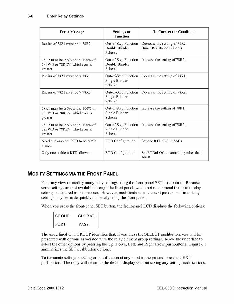
6-6 Enter Relay Settings
Date Code 20001212 SEL-300G Instruction Manual
Error Message Settings or Function
To Correct the Condition:
Radius of 78Z1 must be ≥ 78R2 Out-of-Step FunctionDouble Blinder Scheme
Decrease the setting of 78R2 (Inner Resistance Blinder).
78R2 must be ≥ 5% and ≤ 100% of 78FWD or 78REV, whichever is greater
Out-of-Step FunctionDouble Blinder Scheme
Increase the setting of 78R2.
Radius of 78Z1 must be > 78R1 Out-of-Step FunctionSingle Blinder Scheme
Decrease the setting of 78R1.
Radius of 78Z1 must be > 78R2 Out-of-Step FunctionSingle Blinder Scheme
Decrease the setting of 78R2.
78R1 must be ≥ 5% and ≤ 100% of 78FWD or 78REV, whichever is greater
Out-of-Step FunctionSingle Blinder Scheme
Increase the setting of 78R1.
78R2 must be ≥ 5% and ≤ 100% of 78FWD or 78REV, whichever is greater
Out-of-Step FunctionSingle Blinder Scheme
Increase the setting of 78R2.
Need one ambient RTD to be AMB biased
RTD Configuration Set one RTDnLOC=AMB
Only one ambient RTD allowed RTD Configuration Set RTDnLOC to something other than AMB
MODIFY SETTINGS VIA THE FRONT PANEL You may view or modify many relay settings using the front-panel SET pushbutton. Because some settings are not available through the front panel, we do not recommend that initial relay settings be entered in this manner. However, modifications to element pickup and time-delay settings may be made quickly and easily using the front panel.
When you press the front-panel SET button, the front-panel LCD displays the following options:
GROUP GLOBAL
PORT PASS
The underlined G in GROUP identifies that, if you press the SELECT pushbutton, you will be presented with options associated with the relay element group settings. Move the underline to select the other options by pressing the Up, Down, Left, and Right arrow pushbuttons. Figure 6.1 summarizes the SET pushbutton options.
To terminate settings viewing or modification at any point in the process, press the EXIT pushbutton. The relay will return to the default display without saving any setting modifications.
Enter Relay Settings 6-7
SEL-300G Instruction Manual Date Code 20000616
Within the settings lists, the relay displays the setting category name. Press the SELECT pushbutton to view or modify settings within that category. Use the Up and Down arrow pushbuttons to maneuver within the settings list.
After finding the setting you wish to modify, press the SELECT pushbutton.
Modify numeric settings by using the Left, Right arrow pushbuttons to underline single digits, then the Up, Down arrow pushbuttons to change the digit, similar to moving a thumbwheel.
Modify Y/N enable settings by using the Up, Down arrow pushbuttons to change the setting from Y to N and back.
To learn more about a setting and its range, press the Target Reset/Lamp Test pushbutton while the setting is displayed.
After modifying a setting, press the SELECT pushbutton to proceed to the next setting.
After finishing all setting modifications, press the Down arrow pushbutton several times to proceed to the bottom of the settings list. The relay will display the message:
Save Changes
Yes No
To save your modifications and enable the relay with your new settings, press the SELECT pushbutton with underscore beneath the Y in Yes.
To exit without saving, press the Right arrow pushbutton to move the underscore beneath the N in No, then press the SELECT pushbutton.
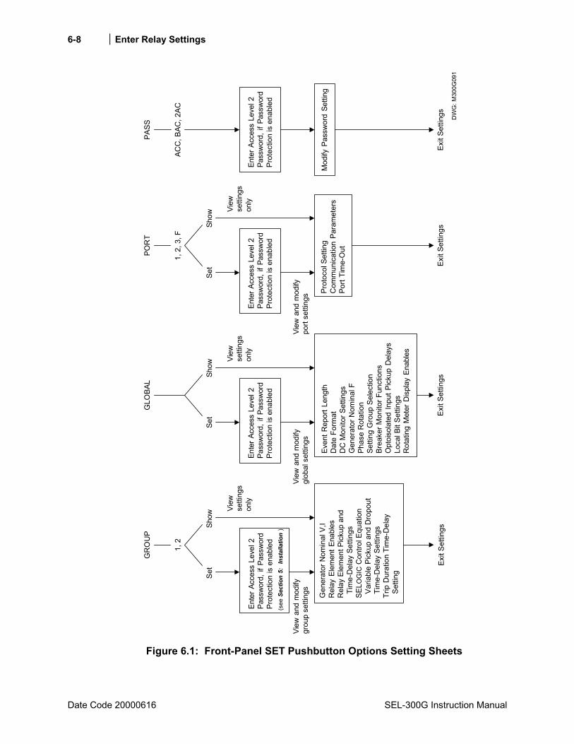
6-8 Enter Relay Settings
Date Code 20000616 SEL-300G Instruction Manual
Set
Show
Exit
Setti
ngs
Prot
ocol
Set
ting
Com
mun
icat
ion
Para
met
ers
Port
Tim
e-O
ut
GR
OU
P
Exit
Setti
ngs
DW
G: M
300G
091
View
and
mod
ifygr
oup
setti
ngs
Even
t Rep
ort L
engt
hD
ate
Form
atD
C M
onito
r Set
tings
Gen
erat
or N
omin
al F
Phas
e R
otat
ion
Setti
ng G
roup
Sel
ectio
nBr
eake
r Mon
itor F
unct
ions
Opt
oiso
late
d In
put P
icku
p D
elay
sLo
cal B
it Se
tting
sR
otat
ing
Met
er D
ispl
ay E
nabl
es
Exit
Setti
ngs
View
setti
ngs
only
GLO
BAL
Set
Show
View
and
mod
ifygl
obal
set
tings
View
setti
ngs
only
POR
T
Set
Show
View
and
mod
ifypo
rt se
tting
s
View
setti
ngs
only
1, 2
1, 2
, 3, F
PASS
ACC
, BAC
, 2AC
Mod
ify P
assw
ord
Setti
ng
Exit
Setti
ngs
Ente
r Acc
ess
Leve
l 2Pa
ssw
ord,
if P
assw
ord
Prot
ectio
n is
ena
bled
(see
Sec
tion
5:
Inst
alla
tion
)
Ente
r Acc
ess
Leve
l 2Pa
ssw
ord,
if P
assw
ord
Prot
ectio
n is
ena
bled
Ente
r Acc
ess
Leve
l 2Pa
ssw
ord,
if P
assw
ord
Prot
ectio
n is
ena
bled
Ente
r Acc
ess
Leve
l 2Pa
ssw
ord,
if P
assw
ord
Prot
ectio
n is
ena
bled
Gen
erat
or N
omin
al V
,IR
elay
Ele
men
t Ena
bles
Rel
ay E
lem
ent P
icku
p an
d T
ime-
Del
ay S
ettin
gsSE
L OG
IC C
ontro
l Equ
atio
n V
aria
ble
Pick
up a
nd D
ropo
ut T
ime-
Del
ay S
ettin
gsTr
ip D
urat
ion
Tim
e-D
elay
Set
ting
Figure 6.1: Front-Panel SET Pushbutton Options Setting Sheets
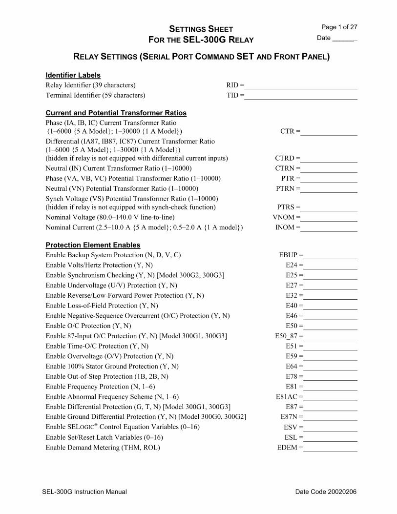
SETTINGS SHEET Page 1 of 27 FOR THE SEL-300G RELAY Date _______
SEL-300G Instruction Manual Date Code 20020206
RELAY SETTINGS (SERIAL PORT COMMAND SET AND FRONT PANEL)
Identifier Labels Relay Identifier (39 characters) RID = Terminal Identifier (59 characters) TID =
Current and Potential Transformer Ratios Phase (IA, IB, IC) Current Transformer Ratio (16000 5 A Model; 130000 1 A Model) CTR = Differential (IA87, IB87, IC87) Current Transformer Ratio (16000 5 A Model; 130000 1 A Model) (hidden if relay is not equipped with differential current inputs) CTRD = Neutral (IN) Current Transformer Ratio (110000) CTRN = Phase (VA, VB, VC) Potential Transformer Ratio (110000) PTR = Neutral (VN) Potential Transformer Ratio (110000) PTRN = Synch Voltage (VS) Potential Transformer Ratio (110000) (hidden if relay is not equipped with synch-check function) PTRS = Nominal Voltage (80.0140.0 V line-to-line) VNOM = Nominal Current (2.510.0 A 5 A model; 0.52.0 A 1 A model) INOM =
Protection Element Enables Enable Backup System Protection (N, D, V, C) EBUP = Enable Volts/Hertz Protection (Y, N) E24 = Enable Synchronism Checking (Y, N) [Model 300G2, 300G3] E25 = Enable Undervoltage (U/V) Protection (Y, N) E27 = Enable Reverse/Low-Forward Power Protection (Y, N) E32 = Enable Loss-of-Field Protection (Y, N) E40 = Enable Negative-Sequence Overcurrent (O/C) Protection (Y, N) E46 = Enable O/C Protection (Y, N) E50 = Enable 87-Input O/C Protection (Y, N) [Model 300G1, 300G3] E50_87 = Enable Time-O/C Protection (Y, N) E51 = Enable Overvoltage (O/V) Protection (Y, N) E59 = Enable 100% Stator Ground Protection (Y, N) E64 = Enable Out-of-Step Protection (1B, 2B, N) E78 = Enable Frequency Protection (N, 16) E81 = Enable Abnormal Frequency Scheme (N, 16) E81AC = Enable Differential Protection (G, T, N) [Model 300G1, 300G3] E87 = Enable Ground Differential Protection (Y, N) [Model 300G0, 300G2] E87N = Enable SELOGIC Control Equation Variables (016) ESV = Enable Set/Reset Latch Variables (016) ESL = Enable Demand Metering (THM, ROL) EDEM =

Page 2 of 27 SETTINGS SHEET Date _______ FOR THE SEL-300G RELAY
SEL-300G Instruction Manual Date Code 20020206
RELAY SETTINGS (SERIAL PORT COMMAND SET AND FRONT PANEL)
21 Elements (hidden when EBUP ≠≠≠≠ D) Zone 1 Phase Distance Reach (OFF, 0.1100.0 Ohms 5 A model; OFF, 0.5500.0 Ohms 1 A model)
Z1R =
Zone 1 Phase Distance Offset (0.010.0 Ohms 5 A model; 0.050.0 Ohms 1 A model) (hidden when Z1R = OFF)
Z1O = Zone 1 Maximum Torque Angle (9045 degrees) (hidden when Z1R = OFF)
MTA1 =
Zone 1 Transformer Compensation (0, -30, 30 degrees) (hidden when Z1R = OFF)
Z1CMP =
Zone 1 Phase Distance Time Delay (0.00 to 400.00 seconds) (hidden when Z1R = bOFF)
Z1D =
Zone 2 Phase Distance Reach (OFF, 0.1100.0 Ohms 5 A model; OFF, 0.5500.0 Ohms 1 A model)
Z2R =
Zone 2 Phase Distance Offset (0.010.0 Ohms 5 A model; 0.050.0 Ohms 1 A model) (hidden when Z2R = OFF)
Z2O = Zone 2 Maximum Torque Angle (9045 degrees) (hidden when Z2R = OFF)
MTA2 =
Zone 2 Transformer Compensation (0, -30, 30 degrees) (hidden when Z2R = OFF)
Z2CMP =
Zone 2 Phase Distance Time-Delay (0.00 to 400.00 seconds) (hidden when Z2R = OFF)
Z2D =
Minimum Power Factor (OFF, 0.980.50) MPF = Maximum Generator Load (0.53.0 per unit) (hidden when MPF = OFF)
MXLD =
21P Element Torque Control (SELOGIC Control Equation) 21PTC =
24 Elements (hidden when E24 = N) Level 1 Volts/Hertz Pickup (100200%) 24D1P = Level 1 Time Delay (0.00400.00 s) 24D1D = Level 2 Composite Curve Shape (OFF, DD, ID, I) 24CCS = Level 2 Inverse-Time Pickup (100200%) (hidden when 24CCS = OFF, DD)
24IP =
Level 2 Inverse-Time Curve (0.5, 1, 2) (hidden when 24CCS = OFF, DD)
24IC =
Level 2 Inverse-Time Factor (0.110.0 s) (hidden when 24CCS = OFF, DD)
24ITD =
Level 2 Pickup One (100200%) (hidden when 24CCS = OFF, ID, I)
24D2P1 =
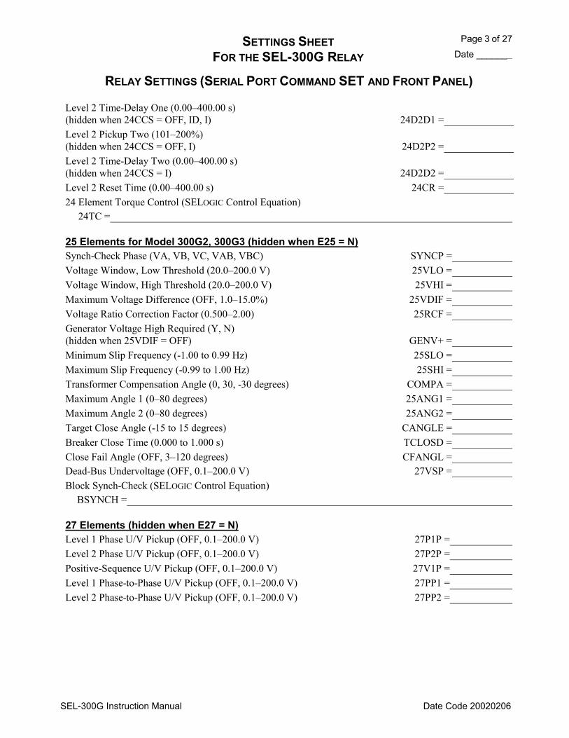
SETTINGS SHEET Page 3 of 27 FOR THE SEL-300G RELAY Date _______
SEL-300G Instruction Manual Date Code 20020206
RELAY SETTINGS (SERIAL PORT COMMAND SET AND FRONT PANEL)
Level 2 Time-Delay One (0.00400.00 s) (hidden when 24CCS = OFF, ID, I)
24D2D1 =
Level 2 Pickup Two (101200%) (hidden when 24CCS = OFF, I)
24D2P2 =
Level 2 Time-Delay Two (0.00400.00 s) (hidden when 24CCS = I)
24D2D2 =
Level 2 Reset Time (0.00400.00 s) 24CR = 24 Element Torque Control (SELOGIC Control Equation)
24TC =
25 Elements for Model 300G2, 300G3 (hidden when E25 = N) Synch-Check Phase (VA, VB, VC, VAB, VBC) SYNCP = Voltage Window, Low Threshold (20.0200.0 V) 25VLO = Voltage Window, High Threshold (20.0200.0 V) 25VHI = Maximum Voltage Difference (OFF, 1.015.0%) 25VDIF = Voltage Ratio Correction Factor (0.5002.00) 25RCF = Generator Voltage High Required (Y, N) (hidden when 25VDIF = OFF)
GENV+ =
Minimum Slip Frequency (-1.00 to 0.99 Hz) 25SLO = Maximum Slip Frequency (-0.99 to 1.00 Hz) 25SHI = Transformer Compensation Angle (0, 30, -30 degrees) COMPA = Maximum Angle 1 (080 degrees) 25ANG1 = Maximum Angle 2 (080 degrees) 25ANG2 = Target Close Angle (-15 to 15 degrees) CANGLE = Breaker Close Time (0.000 to 1.000 s) TCLOSD = Close Fail Angle (OFF, 3120 degrees) CFANGL = Dead-Bus Undervoltage (OFF, 0.1200.0 V) 27VSP = Block Synch-Check (SELOGIC Control Equation)
BSYNCH =
27 Elements (hidden when E27 = N) Level 1 Phase U/V Pickup (OFF, 0.1200.0 V) 27P1P = Level 2 Phase U/V Pickup (OFF, 0.1200.0 V) 27P2P = Positive-Sequence U/V Pickup (OFF, 0.1200.0 V) 27V1P = Level 1 Phase-to-Phase U/V Pickup (OFF, 0.1200.0 V) 27PP1 = Level 2 Phase-to-Phase U/V Pickup (OFF, 0.1200.0 V) 27PP2 =
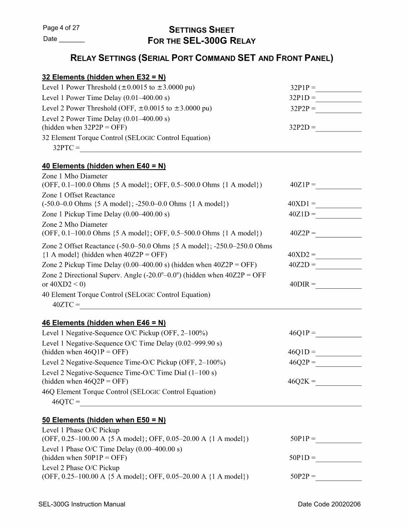
Page 4 of 27 SETTINGS SHEET Date _______ FOR THE SEL-300G RELAY
SEL-300G Instruction Manual Date Code 20020206
RELAY SETTINGS (SERIAL PORT COMMAND SET AND FRONT PANEL)
32 Elements (hidden when E32 = N) Level 1 Power Threshold (0.0015 to 3.0000 pu) 32P1P = Level 1 Power Time Delay (0.01400.00 s) 32P1D = Level 2 Power Threshold (OFF, 0.0015 to 3.0000 pu) 32P2P = Level 2 Power Time Delay (0.01400.00 s) (hidden when 32P2P = OFF) 32P2D = 32 Element Torque Control (SELOGIC Control Equation)
32PTC =
40 Elements (hidden when E40 = N) Zone 1 Mho Diameter (OFF, 0.1100.0 Ohms 5 A model; OFF, 0.5500.0 Ohms 1 A model) 40Z1P = Zone 1 Offset Reactance (-50.00.0 Ohms 5 A model; -250.00.0 Ohms 1 A model) 40XD1 = Zone 1 Pickup Time Delay (0.00400.00 s) 40Z1D = Zone 2 Mho Diameter (OFF, 0.1100.0 Ohms 5 A model; OFF, 0.5500.0 Ohms 1 A model) 40Z2P =
Zone 2 Offset Reactance (-50.050.0 Ohms 5 A model; -250.0250.0 Ohms 1 A model (hidden when 40Z2P = OFF) 40XD2 = Zone 2 Pickup Time Delay (0.00400.00 s) (hidden when 40Z2P = OFF) 40Z2D = Zone 2 Directional Superv. Angle (-20.00.0) (hidden when 40Z2P = OFF or 40XD2 < 0) 40DIR = 40 Element Torque Control (SELOGIC Control Equation)
40ZTC =
46 Elements (hidden when E46 = N) Level 1 Negative-Sequence O/C Pickup (OFF, 2100%) 46Q1P = Level 1 Negative-Sequence O/C Time Delay (0.02999.90 s) (hidden when 46Q1P = OFF) 46Q1D = Level 2 Negative-Sequence Time-O/C Pickup (OFF, 2100%) 46Q2P = Level 2 Negative-Sequence Time-O/C Time Dial (1100 s) (hidden when 46Q2P = OFF) 46Q2K = 46Q Element Torque Control (SELOGIC Control Equation)
46QTC =
50 Elements (hidden when E50 = N) Level 1 Phase O/C Pickup (OFF, 0.25100.00 A 5 A model; OFF, 0.0520.00 A 1 A model) 50P1P = Level 1 Phase O/C Time Delay (0.00400.00 s) (hidden when 50P1P = OFF) 50P1D = Level 2 Phase O/C Pickup (OFF, 0.25100.00 A 5 A model; OFF, 0.0520.00 A 1 A model) 50P2P =
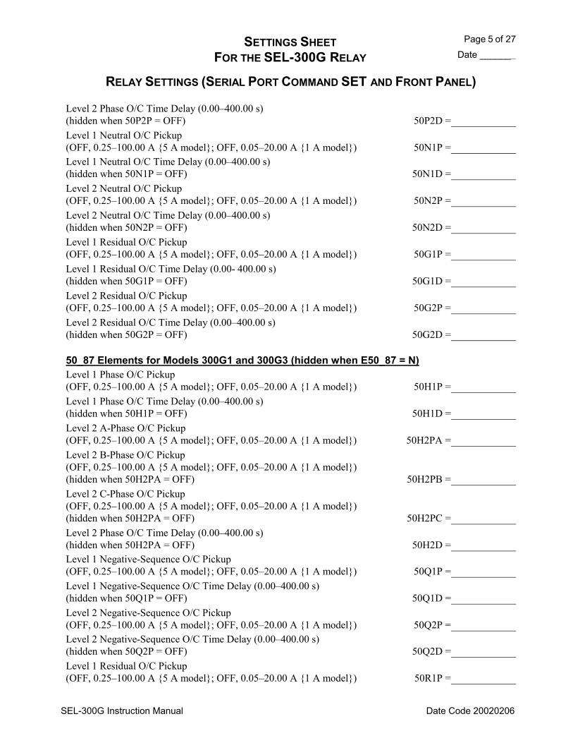
SETTINGS SHEET Page 5 of 27 FOR THE SEL-300G RELAY Date _______
SEL-300G Instruction Manual Date Code 20020206
RELAY SETTINGS (SERIAL PORT COMMAND SET AND FRONT PANEL)
Level 2 Phase O/C Time Delay (0.00400.00 s) (hidden when 50P2P = OFF) 50P2D = Level 1 Neutral O/C Pickup (OFF, 0.25100.00 A 5 A model; OFF, 0.0520.00 A 1 A model) 50N1P = Level 1 Neutral O/C Time Delay (0.00400.00 s) (hidden when 50N1P = OFF) 50N1D = Level 2 Neutral O/C Pickup (OFF, 0.25100.00 A 5 A model; OFF, 0.0520.00 A 1 A model) 50N2P = Level 2 Neutral O/C Time Delay (0.00400.00 s) (hidden when 50N2P = OFF) 50N2D = Level 1 Residual O/C Pickup (OFF, 0.25100.00 A 5 A model; OFF, 0.0520.00 A 1 A model) 50G1P = Level 1 Residual O/C Time Delay (0.00- 400.00 s) (hidden when 50G1P = OFF) 50G1D = Level 2 Residual O/C Pickup (OFF, 0.25100.00 A 5 A model; OFF, 0.0520.00 A 1 A model) 50G2P = Level 2 Residual O/C Time Delay (0.00400.00 s) (hidden when 50G2P = OFF) 50G2D =
50_87 Elements for Models 300G1 and 300G3 (hidden when E50_87 = N) Level 1 Phase O/C Pickup (OFF, 0.25100.00 A 5 A model; OFF, 0.0520.00 A 1 A model) 50H1P = Level 1 Phase O/C Time Delay (0.00400.00 s) (hidden when 50H1P = OFF) 50H1D = Level 2 A-Phase O/C Pickup (OFF, 0.25100.00 A 5 A model; OFF, 0.0520.00 A 1 A model) 50H2PA = Level 2 B-Phase O/C Pickup (OFF, 0.25100.00 A 5 A model; OFF, 0.0520.00 A 1 A model) (hidden when 50H2PA = OFF) 50H2PB = Level 2 C-Phase O/C Pickup (OFF, 0.25100.00 A 5 A model; OFF, 0.0520.00 A 1 A model) (hidden when 50H2PA = OFF) 50H2PC = Level 2 Phase O/C Time Delay (0.00400.00 s) (hidden when 50H2PA = OFF) 50H2D = Level 1 Negative-Sequence O/C Pickup (OFF, 0.25100.00 A 5 A model; OFF, 0.0520.00 A 1 A model) 50Q1P = Level 1 Negative-Sequence O/C Time Delay (0.00400.00 s) (hidden when 50Q1P = OFF) 50Q1D = Level 2 Negative-Sequence O/C Pickup (OFF, 0.25100.00 A 5 A model; OFF, 0.0520.00 A 1 A model) 50Q2P = Level 2 Negative-Sequence O/C Time Delay (0.00400.00 s) (hidden when 50Q2P = OFF) 50Q2D = Level 1 Residual O/C Pickup (OFF, 0.25100.00 A 5 A model; OFF, 0.0520.00 A 1 A model) 50R1P =
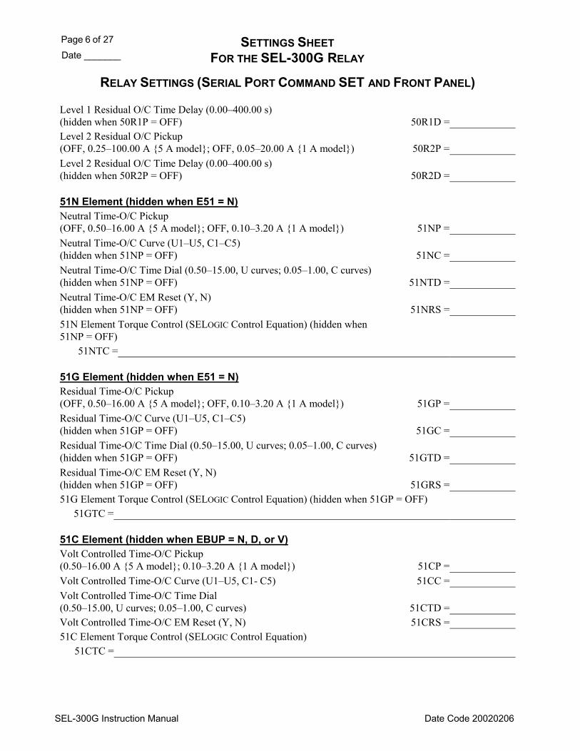
Page 6 of 27 SETTINGS SHEET Date _______ FOR THE SEL-300G RELAY
SEL-300G Instruction Manual Date Code 20020206
RELAY SETTINGS (SERIAL PORT COMMAND SET AND FRONT PANEL)
Level 1 Residual O/C Time Delay (0.00400.00 s) (hidden when 50R1P = OFF) 50R1D = Level 2 Residual O/C Pickup (OFF, 0.25100.00 A 5 A model; OFF, 0.0520.00 A 1 A model) 50R2P = Level 2 Residual O/C Time Delay (0.00400.00 s) (hidden when 50R2P = OFF) 50R2D =
51N Element (hidden when E51 = N) Neutral Time-O/C Pickup (OFF, 0.5016.00 A 5 A model; OFF, 0.103.20 A 1 A model) 51NP = Neutral Time-O/C Curve (U1U5, C1C5) (hidden when 51NP = OFF) 51NC = Neutral Time-O/C Time Dial (0.5015.00, U curves; 0.051.00, C curves) (hidden when 51NP = OFF) 51NTD = Neutral Time-O/C EM Reset (Y, N) (hidden when 51NP = OFF) 51NRS = 51N Element Torque Control (SELOGIC Control Equation) (hidden when 51NP = OFF)
51NTC =
51G Element (hidden when E51 = N) Residual Time-O/C Pickup (OFF, 0.5016.00 A 5 A model; OFF, 0.103.20 A 1 A model) 51GP = Residual Time-O/C Curve (U1U5, C1C5) (hidden when 51GP = OFF) 51GC = Residual Time-O/C Time Dial (0.5015.00, U curves; 0.051.00, C curves) (hidden when 51GP = OFF) 51GTD = Residual Time-O/C EM Reset (Y, N) (hidden when 51GP = OFF) 51GRS = 51G Element Torque Control (SELOGIC Control Equation) (hidden when 51GP = OFF)
51GTC =
51C Element (hidden when EBUP = N, D, or V) Volt Controlled Time-O/C Pickup (0.5016.00 A 5 A model; 0.103.20 A 1 A model) 51CP = Volt Controlled Time-O/C Curve (U1U5, C1- C5) 51CC = Volt Controlled Time-O/C Time Dial (0.5015.00, U curves; 0.051.00, C curves) 51CTD = Volt Controlled Time-O/C EM Reset (Y, N) 51CRS = 51C Element Torque Control (SELOGIC Control Equation)
51CTC =

SETTINGS SHEET Page 7 of 27 FOR THE SEL-300G RELAY Date _______
SEL-300G Instruction Manual Date Code 20020206
RELAY SETTINGS (SERIAL PORT COMMAND SET AND FRONT PANEL)
51V Element (hidden when EBUP = N, D, or C) Volt Restrained Time-O/C Pickup (2.0016.00 A 5 A model; 0.403.20 A 1 A model) 51VP = Volt Restrained Time-O/C Curve (U1U5, C1C5) 51VC = Volt Restrained Time-O/C Time Dial (0.5015.00, U curves; 0.051.00, C curves) 51VTD = Volt Restrained Time-O/C EM Reset (Y, N) 51VRS = 51V Element Torque Control (SELOGIC Control Equation)
51VTC =
Open Pole Element Three-Pole Open Time Delay (0.001.00 s) 3POD = Load Detection Phase Pickup (OFF, 0.25100.00 A 5 A model; OFF, 0.0520.00 A 1 A model) 50LP = Generator Breaker Auxiliary (SELOGIC Control Equation)
52A =
59 Elements (hidden when E59 = N) Level 1 Phase O/V Pickup (OFF, 0.0200.0 V) 59P1P = Level 2 Phase O/V Pickup (OFF, 0.0200.0 V) 59P2P = Level 1 Residual O/V Pickup (OFF, 0.0200.0 V) 59G1P = Level 2 Residual O/V Pickup (OFF, 0.0200.0 V) 59G2P = Negative-Sequence (V2) O/V Pickup (OFF, 0.0200.0 V) 59QP = Positive-Sequence (V1) O/V Pickup (OFF, 0.0200.0 V) 59V1P = Level 1 Phase-to-Phase O/V Pickup (OFF, 0.0200.0 V) 59PP1 = Level 2 Phase-to-Phase O/V Pickup (OFF, 0.0200.0 V) 59PP2 =
64G Elements (hidden when E64 = N) Zone 1 Neutral O/V Pickup (OFF, 0.1150.0 V) 64G1P = Zone 1 Time Delay (0.00400.00 s) (hidden when 64G1P = OFF) 64G1D = Zone 2 Differential Voltage (OFF, 0.120.0 V) 64G2P = Zone 2 Ratio Setting (0.05.0) (hidden when 64G2P = OFF or when DELTA_Y = D) 64RAT = Zone 2 Time Delay (0.00400.00 s) (hidden when 64G2P = OFF) 64G2D = 64G Element Torque Control (SELOGIC Control Equation)
64GTC =
78 Elements (hidden when E78 = N) If E78 = 1B, the following settings will apply: Forward Reach Reactance (0.1100.0 Ohms 5 A model; 0.5500.0 Ohms 1 A model) 78FWD = Reverse Reach Reactance 78REV =

Page 8 of 27 SETTINGS SHEET Date _______ FOR THE SEL-300G RELAY
SEL-300G Instruction Manual Date Code 20020206
RELAY SETTINGS (SERIAL PORT COMMAND SET AND FRONT PANEL)
(0.1100.0 Ohms 5 A model; 0.5500.0 Ohms 1 A model) Right-Hand Blinder (0.150.0 Ohms 5 A model; 0.5250.0 Ohms 1 A model) 78R1 = Left-Hand Blinder (0.150.0 Ohms 5 A model; 0.5250.0 Ohms 1 A model) 78R2 = Out-of-Step Trip Delay (0.001.00 s) 78TD = Out-of-Step Trip Duration (0.005.00 s) 78TDURD = Positive-Sequence Current Supervision (0.2530.00 A 5 A model; 0.056.00 A 1 A model) 50ABC = 78 Element Torque Control (SELOGIC Control Equation)
OOSTC = If E78 = 2B, the following settings will apply: Forward Reach Reactance (0.1100.0 Ohms 5 A model; 0.5500.0 Ohms 1 A model) 78FWD = Reverse Reach Reactance (0.1100.0 Ohms 5 A model; 0.5500.0 Ohms 1 A model) 78REV = Outer Resistance Blinder (0.2100.0 Ohms 5 A model; 1.0500.0 Ohms 1 A model) 78R1 = Inner Resistance Blinder (0.150 Ohms 5 A model; 0.5250 Ohms 1 A model) 78R2 = Out-of-Step Delay (0.001.00 s) 78D = Out-of-Step Trip Delay (0.001.00 s) 78TD = Out-of-Step Trip Duration (0.005.00 s) 78TDURD = Positive-Sequence Current Supervision (0.2530.00 A 5 A model; 0.056.00 A 1 A model) 50ABC = 78 Element Torque Control (SELOGIC Control Equation)
OOSTC =
81 Elements (hidden when E81 = N) Undervoltage Block (20.0150.0 V) 27B81P = Level 1 Pickup (OFF, 20.0070.00 Hz) 81D1P = Level 1 Time Delay (0.03400.00 s) (hidden when 81D1P = OFF) 81D1D = Level 2 Pickup (OFF, 20.0070.00 Hz) (hidden when E81 < 2) 81D2P = Level 2 Time Delay (0.03400.00 s) (hidden when E81 < 2 or 81D2P = OFF) 81D2D = Level 3 Pickup (OFF, 20.0070.00 Hz) (hidden when E81 < 3) 81D3P = Level 3 Time Delay (0.03400.00 s) (hidden when E81 < 3 or 81D3P = OFF) 81D3D = Level 4 Pickup (OFF, 20.0070.00 Hz) (hidden when E81 < 4) 81D4P = Level 4 Time Delay (0.03400.00 s) (hidden when E81 < 4 or 81D4P = OFF) 81D4D = Level 5 Pickup (OFF, 20.0070.00 Hz) (hidden when E81 < 5) 81D5P =

SETTINGS SHEET Page 9 of 27 FOR THE SEL-300G RELAY Date _______
SEL-300G Instruction Manual Date Code 20020206
RELAY SETTINGS (SERIAL PORT COMMAND SET AND FRONT PANEL)
Level 5 Time Delay (0.03400.00 s) (hidden when E81 < 5 or 81D5P = OFF) 81D5D = Level 6 Pickup (OFF, 20.0070.00 Hz) (hidden when E81 < 6) 81D6P = Level 6 Time Delay (0.03400.00 s) (hidden when E81 < 6 or 81D6P = OFF) 81D6D =
81AC Elements (hidden when E81AC = N) Upper Frequency Limit of Band 1 (20.070.0 Hz) UBND1 = Lower Frequency Limit of Band 1 (20.070.0 Hz) LBND1 = Band 1 Accumulator Limit Time (0.016000.00 s) TBND1 = Lower Frequency Limit of Band 2 (20.070.0 Hz) (hidden when E81AC < 2) LBND2 = Band 2 Accumulator Limit Time (0.016000.00 s) (hidden when E81AC < 2) TBND2 = Lower Frequency Limit of Band 3 (20.070.0 Hz) (hidden when E81AC < 3) LBND3 = Band 3 Accumulator Limit Time (0.016000.00 s) (hidden when E81AC < 3) TBND3 = Lower Frequency Limit of Band 4 (20.070.0 Hz) (hidden when E81AC < 4) LBND4 = Band 4 Accumulator Limit Time (0.016000.00 s) (hidden when E81AC < 4) TBND4 = Lower Frequency Limit of Band 5 (20.070.0 Hz) (hidden when E81AC < 5) LBND5 = Band 5 Accumulator Limit Time (0.016000.00 s) (hidden when E81AC < 5) TBND5 = Lower Frequency Limit of Band 6 (20.070.0 Hz) (hidden when E81AC < 6) LBND6 = Band 6 Accumulator Limit Time (0.016000.00 s) (hidden when E81AC < 6) TBND6 = Accumulator Time-Delayed Pickup (0.00400.00 s) 62ACC = Abnormal Frequency Element Control (SELOGIC Control Equation) ONLINE =
87N Elements for Model 0300G0, 0300G2 (hidden when E87N = N) Level 1 Ground Differential Pickup (0.1 CTR/CTRN to 15.0 A 5 A model; 0.02 CTR/CTRN to 3.00 A 1 A model) 87N1P = Level 1 Ground Differential Time Delay (0.00 to 400.00 s) 87N1D =
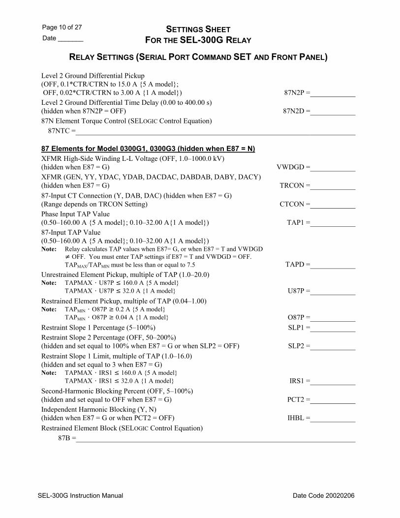
Page 10 of 27 SETTINGS SHEET Date _______ FOR THE SEL-300G RELAY
SEL-300G Instruction Manual Date Code 20020206
RELAY SETTINGS (SERIAL PORT COMMAND SET AND FRONT PANEL)
Level 2 Ground Differential Pickup (OFF, 0.1*CTR/CTRN to 15.0 A 5 A model; OFF, 0.02*CTR/CTRN to 3.00 A 1 A model) 87N2P = Level 2 Ground Differential Time Delay (0.00 to 400.00 s) (hidden when 87N2P = OFF) 87N2D = 87N Element Torque Control (SELOGIC Control Equation)
87NTC =
87 Elements for Model 0300G1, 0300G3 (hidden when E87 = N) XFMR High-Side Winding L-L Voltage (OFF, 1.01000.0 kV) (hidden when E87 = G) VWDGD = XFMR (GEN, YY, YDAC, YDAB, DACDAC, DABDAB, DABY, DACY) (hidden when E87 = G) TRCON = 87-Input CT Connection (Y, DAB, DAC) (hidden when E87 = G) (Range depends on TRCON Setting) CTCON = Phase Input TAP Value (0.50160.00 A 5 A model; 0.1032.00 A1 A model) TAP1 = 87-Input TAP Value (0.50160.00 A 5 A model; 0.1032.00 A1 A model) Note: Relay calculates TAP values when E87= G, or when E87 = T and VWDGD
OFF. You must enter TAP settings if E87 = T and VWDGD = OFF. TAPMAX/TAPMIN must be less than or equal to 7.5 TAPD =
Unrestrained Element Pickup, multiple of TAP (1.020.0) Note: TAPMAX U87P 160.0 A 5 A model
TAPMAX U87P 32.0 A 1 A model U87P = Restrained Element Pickup, multiple of TAP (0.041.00) Note: TAPMIN O87P 0.2 A 5 A model
TAPMIN O87P 0.04 A 1 A model O87P = Restraint Slope 1 Percentage (5100%) SLP1 = Restraint Slope 2 Percentage (OFF, 50200%) (hidden and set equal to 100% when E87 = G or when SLP2 = OFF) SLP2 = Restraint Slope 1 Limit, multiple of TAP (1.016.0) (hidden and set equal to 3 when E87 = G) Note: TAPMAX IRS1 160.0 A 5 A model
TAPMAX IRS1 32.0 A 1 A model IRS1 = Second-Harmonic Blocking Percent (OFF, 5100%) (hidden and set equal to OFF when E87 = G) PCT2 = Independent Harmonic Blocking (Y, N) (hidden when E87 = G or when PCT2 = OFF) IHBL = Restrained Element Block (SELOGIC Control Equation)
87B =

SETTINGS SHEET Page 11 of 27 FOR THE SEL-300G RELAY Date _______
SEL-300G Instruction Manual Date Code 20020206
RELAY SETTINGS (SERIAL PORT COMMAND SET AND FRONT PANEL)
RTD Based Protection for Models Compatible With the SEL-2600 Module RTD Input Option (EXT, NONE) RTDOPT = (Following Settings are hidden when RTDOPT=NONE) Temperature Preference Setting (C, F) TMPREF =
RTD Location (WDG, BRG, AMB, OTH, NONE) RTD1LOC = RTD Location (WDG, BRG, AMB, OTH, NONE) RTD2LOC = RTD Location (WDG, BRG, AMB, OTH, NONE) RTD3LOC = RTD Location (WDG, BRG, AMB, OTH, NONE) RTD4LOC = RTD Location (WDG, BRG, AMB, OTH, NONE) RTD5LOC = RTD Location (WDG, BRG, AMB, OTH, NONE) RTD6LOC = RTD Location (WDG, BRG, AMB, OTH, NONE) RTD7LOC = RTD Location (WDG, BRG, AMB, OTH, NONE) RTD8LOC = RTD Location (WDG, BRG, AMB, OTH, NONE) RTD9LOC = RTD Location (WDG, BRG, AMB, OTH, NONE) RTD10LOC = RTD Location (WDG, BRG, AMB, OTH, NONE) RTD11LOC = RTD Location (WDG, BRG, AMB, OTH, NONE) RTD12LOC = RTD Type (PT100, NI100, NI120, CU10) RTD1TY = RTD Type (PT100, NI100, NI120, CU10) RTD2TY = RTD Type (PT100, NI100, NI120, CU10) RTD3TY = RTD Type (PT100, NI100, NI120, CU10) RTD4TY = RTD Type (PT100, NI100, NI120, CU10) RTD5TY = RTD Type (PT100, NI100, NI120, CU10) RTD6TY = RTD Type (PT100, NI100, NI120, CU10) RTD7TY = RTD Type (PT100, NI100, NI120, CU10) RTD8TY = RTD Type (PT100, NI100, NI120, CU10) RTD9TY = RTD Type (PT100, NI100, NI120, CU10) RTD10TY = RTD Type (PT100, NI100, NI120, CU10) RTD11TY = RTD Type (PT100, NI100, NI120, CU10) RTD12TY = RTD Trip Temperature (OFF, 32°482°F or 0°250°C) TRTMP1 = RTD Alarm Temperature (OFF, 32°482°F or 0°250°C) ALTMP1 = RTD Trip Temperature (OFF, 32°482°F or 0°250°C) TRTMP2 = RTD Alarm Temperature (OFF, 32°482°F or 0°250°C) ALTMP2 = RTD Trip Temperature (OFF, 32°482°F or 0°250°C) TRTMP3 = RTD Alarm Temperature (OFF, 32°482°F or 0°250°C) ALTMP3 = RTD Trip Temperature (OFF, 32°482°F or 0°250°C) TRTMP4 = RTD Alarm Temperature (OFF, 32°482°F or 0°250°C) ALTMP4 = RTD Trip Temperature (OFF, 32°482°F or 0°250°C) TRTMP5 = RTD Alarm Temperature (OFF, 32°482°F or 0°250°C) ALTMP5 = RTD Trip Temperature (OFF, 32°482°F or 0°250°C) TRTMP6 = RTD Alarm Temperature (OFF, 32°482°F or 0°250°C) ALTMP6 =
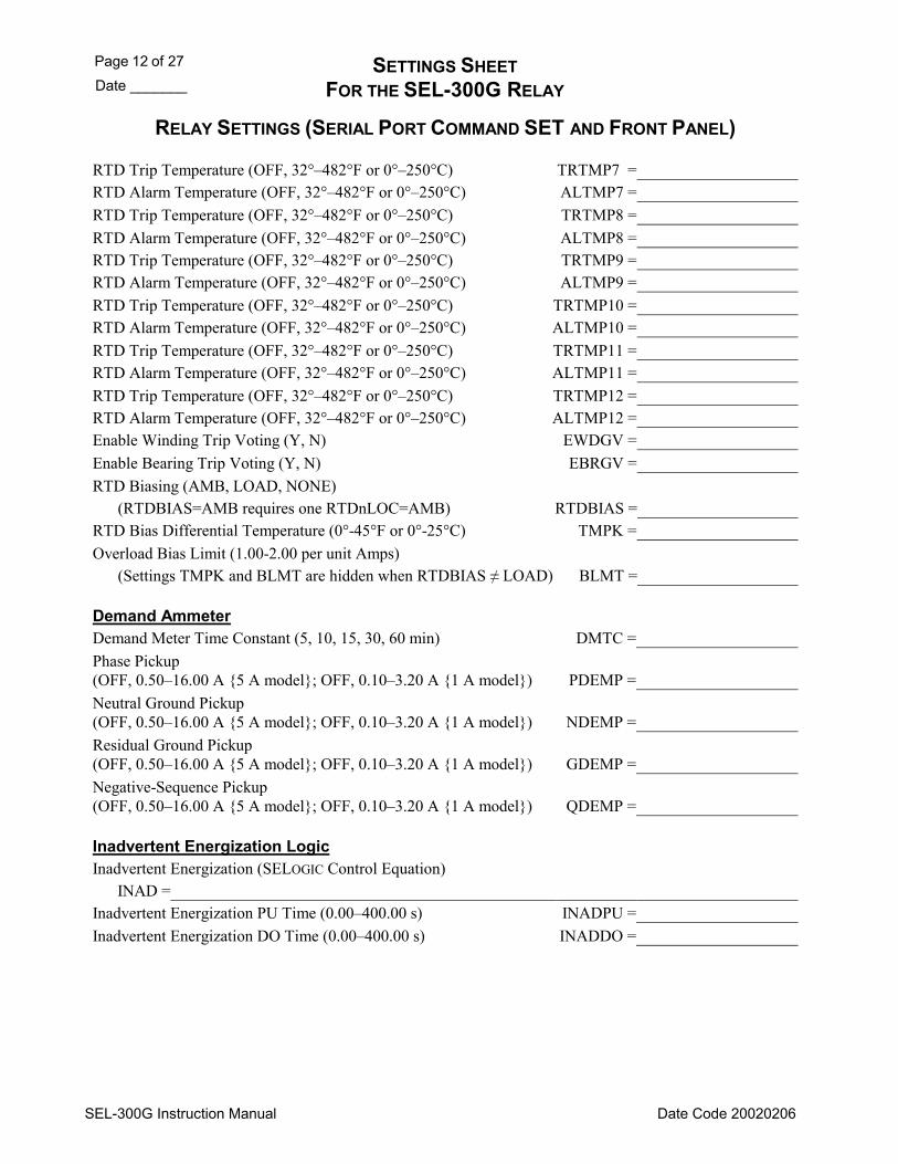
Page 12 of 27 SETTINGS SHEET Date _______ FOR THE SEL-300G RELAY
SEL-300G Instruction Manual Date Code 20020206
RELAY SETTINGS (SERIAL PORT COMMAND SET AND FRONT PANEL)
RTD Trip Temperature (OFF, 32°482°F or 0°250°C) TRTMP7 = RTD Alarm Temperature (OFF, 32°482°F or 0°250°C) ALTMP7 = RTD Trip Temperature (OFF, 32°482°F or 0°250°C) TRTMP8 = RTD Alarm Temperature (OFF, 32°482°F or 0°250°C) ALTMP8 = RTD Trip Temperature (OFF, 32°482°F or 0°250°C) TRTMP9 = RTD Alarm Temperature (OFF, 32°482°F or 0°250°C) ALTMP9 = RTD Trip Temperature (OFF, 32°482°F or 0°250°C) TRTMP10 = RTD Alarm Temperature (OFF, 32°482°F or 0°250°C) ALTMP10 = RTD Trip Temperature (OFF, 32°482°F or 0°250°C) TRTMP11 = RTD Alarm Temperature (OFF, 32°482°F or 0°250°C) ALTMP11 = RTD Trip Temperature (OFF, 32°482°F or 0°250°C) TRTMP12 = RTD Alarm Temperature (OFF, 32°482°F or 0°250°C) ALTMP12 = Enable Winding Trip Voting (Y, N) EWDGV = Enable Bearing Trip Voting (Y, N) EBRGV = RTD Biasing (AMB, LOAD, NONE) (RTDBIAS=AMB requires one RTDnLOC=AMB) RTDBIAS = RTD Bias Differential Temperature (0°-45°F or 0°-25°C) TMPK = Overload Bias Limit (1.00-2.00 per unit Amps) (Settings TMPK and BLMT are hidden when RTDBIAS ≠ LOAD) BLMT =
Demand Ammeter Demand Meter Time Constant (5, 10, 15, 30, 60 min) DMTC = Phase Pickup (OFF, 0.5016.00 A 5 A model; OFF, 0.103.20 A 1 A model) PDEMP = Neutral Ground Pickup (OFF, 0.5016.00 A 5 A model; OFF, 0.103.20 A 1 A model) NDEMP = Residual Ground Pickup (OFF, 0.5016.00 A 5 A model; OFF, 0.103.20 A 1 A model) GDEMP = Negative-Sequence Pickup (OFF, 0.5016.00 A 5 A model; OFF, 0.103.20 A 1 A model) QDEMP =
Inadvertent Energization Logic Inadvertent Energization (SELOGIC Control Equation)
INAD = Inadvertent Energization PU Time (0.00400.00 s) INADPU = Inadvertent Energization DO Time (0.00400.00 s) INADDO =

SETTINGS SHEET Page 13 of 27 FOR THE SEL-300G RELAY Date _______
SEL-300G Instruction Manual Date Code 20020206
RELAY SETTINGS (SERIAL PORT COMMAND SET AND FRONT PANEL)
SELOGIC Control Equation Variable Timers (only set those variables and timers enabled by ESV) SELOGIC Control Equation Variable SV1
SV1 = SV1 Pickup Time (0.003000.00 s) SV1PU = SV1 Dropout Time (0.003000.00 s) SV1DO = SELOGIC Control Equation Variable SV2
SV2 = SV2 Pickup Time (0.003000.00 s) SV2PU = SV2 Dropout Time (0.003000.00 s) SV2DO = SELOGIC Control Equation Variable SV3
SV3 = SV3 Pickup Time (0.003000.00 s) SV3PU = SV3 Dropout Time (0.003000.00 s) SV3DO = SELOGIC Control Equation Variable SV4
SV4 = SV4 Pickup Time (0.003000.00 s) SV4PU = SV4 Dropout Time (0.003000.00 s) SV4DO = SELOGIC Control Equation Variable SV5
SV5 = SV5 Pickup Time (0.003000.00 s) SV5PU = SV5 Dropout Time (0.003000.00 s) SV5DO = SELOGIC Control Equation Variable SV6
SV6 = SV6 Pickup Time (0.003000.00 s) SV6PU = SV6 Dropout Time (0.003000.00 s) SV6DO = SELOGIC Control Equation Variable SV7
SV7 = SV7 Pickup Time (0.003000.00 s) SV7PU = SV7 Dropout Time (0.003000.00 s) SV7DO = SELOGIC Control Equation Variable SV8
SV8 = SV8 Pickup Time (0.003000.00 s) SV8PU = SV8 Dropout Time (0.003000.00 s) SV8DO = SELOGIC Control Equation Variable SV9
SV9 = SV9 Pickup Time (0.003000.00 s) SV9PU = SV9 Dropout Time (0.003000.00 s) SV9DO =
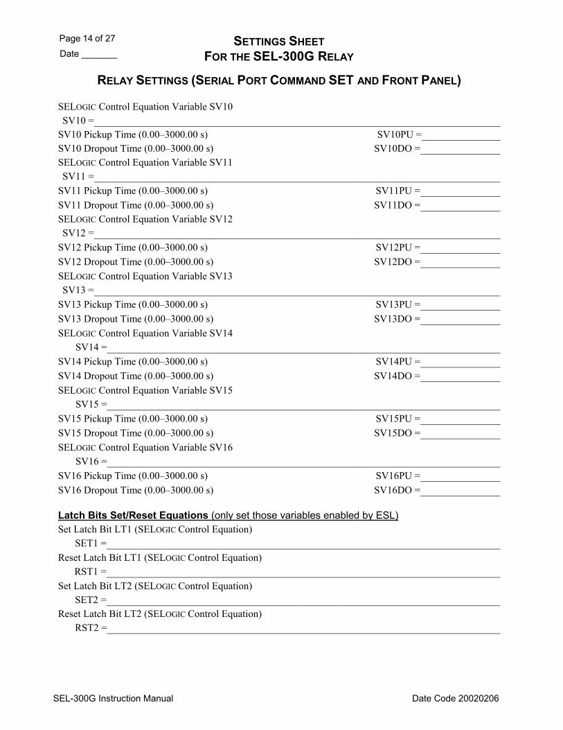
Page 14 of 27 SETTINGS SHEET Date _______ FOR THE SEL-300G RELAY
SEL-300G Instruction Manual Date Code 20020206
RELAY SETTINGS (SERIAL PORT COMMAND SET AND FRONT PANEL)
SELOGIC Control Equation Variable SV10 SV10 =
SV10 Pickup Time (0.003000.00 s) SV10PU = SV10 Dropout Time (0.003000.00 s) SV10DO = SELOGIC Control Equation Variable SV11 SV11 =
SV11 Pickup Time (0.003000.00 s) SV11PU = SV11 Dropout Time (0.003000.00 s) SV11DO = SELOGIC Control Equation Variable SV12 SV12 =
SV12 Pickup Time (0.003000.00 s) SV12PU = SV12 Dropout Time (0.003000.00 s) SV12DO = SELOGIC Control Equation Variable SV13 SV13 =
SV13 Pickup Time (0.003000.00 s) SV13PU = SV13 Dropout Time (0.003000.00 s) SV13DO = SELOGIC Control Equation Variable SV14
SV14 = SV14 Pickup Time (0.003000.00 s) SV14PU = SV14 Dropout Time (0.003000.00 s) SV14DO = SELOGIC Control Equation Variable SV15
SV15 = SV15 Pickup Time (0.003000.00 s) SV15PU = SV15 Dropout Time (0.003000.00 s) SV15DO = SELOGIC Control Equation Variable SV16
SV16 = SV16 Pickup Time (0.003000.00 s) SV16PU = SV16 Dropout Time (0.003000.00 s) SV16DO =
Latch Bits Set/Reset Equations (only set those variables enabled by ESL) Set Latch Bit LT1 (SELOGIC Control Equation)
SET1 = Reset Latch Bit LT1 (SELOGIC Control Equation)
RST1 = Set Latch Bit LT2 (SELOGIC Control Equation)
SET2 = Reset Latch Bit LT2 (SELOGIC Control Equation)
RST2 =
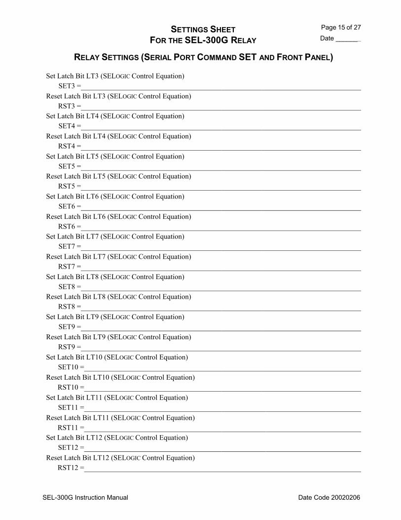
SETTINGS SHEET Page 15 of 27 FOR THE SEL-300G RELAY Date _______
SEL-300G Instruction Manual Date Code 20020206
RELAY SETTINGS (SERIAL PORT COMMAND SET AND FRONT PANEL)
Set Latch Bit LT3 (SELOGIC Control Equation) SET3 =
Reset Latch Bit LT3 (SELOGIC Control Equation) RST3 =
Set Latch Bit LT4 (SELOGIC Control Equation) SET4 =
Reset Latch Bit LT4 (SELOGIC Control Equation) RST4 =
Set Latch Bit LT5 (SELOGIC Control Equation) SET5 =
Reset Latch Bit LT5 (SELOGIC Control Equation) RST5 =
Set Latch Bit LT6 (SELOGIC Control Equation) SET6 =
Reset Latch Bit LT6 (SELOGIC Control Equation) RST6 =
Set Latch Bit LT7 (SELOGIC Control Equation) SET7 =
Reset Latch Bit LT7 (SELOGIC Control Equation) RST7 =
Set Latch Bit LT8 (SELOGIC Control Equation) SET8 =
Reset Latch Bit LT8 (SELOGIC Control Equation) RST8 =
Set Latch Bit LT9 (SELOGIC Control Equation) SET9 =
Reset Latch Bit LT9 (SELOGIC Control Equation) RST9 =
Set Latch Bit LT10 (SELOGIC Control Equation) SET10 =
Reset Latch Bit LT10 (SELOGIC Control Equation) RST10 =
Set Latch Bit LT11 (SELOGIC Control Equation) SET11 =
Reset Latch Bit LT11 (SELOGIC Control Equation) RST11 =
Set Latch Bit LT12 (SELOGIC Control Equation) SET12 =
Reset Latch Bit LT12 (SELOGIC Control Equation) RST12 =
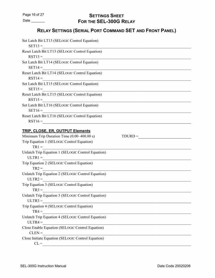
Page 16 of 27 SETTINGS SHEET Date _______ FOR THE SEL-300G RELAY
SEL-300G Instruction Manual Date Code 20020206
RELAY SETTINGS (SERIAL PORT COMMAND SET AND FRONT PANEL)
Set Latch Bit LT13 (SELOGIC Control Equation) SET13 =
Reset Latch Bit LT13 (SELOGIC Control Equation) RST13 =
Set Latch Bit LT14 (SELOGIC Control Equation) SET14 =
Reset Latch Bit LT14 (SELOGIC Control Equation) RST14 =
Set Latch Bit LT15 (SELOGIC Control Equation) SET15 =
Reset Latch Bit LT15 (SELOGIC Control Equation) RST15 =
Set Latch Bit LT16 (SELOGIC Control Equation) SET16 =
Reset Latch Bit LT16 (SELOGIC Control Equation) RST16 =
TRIP, CLOSE, ER, OUTPUT Elements Minimum Trip Duration Time (0.00400.00 s) TDURD = Trip Equation 1 (SELOGIC Control Equation)
TR1 = Unlatch Trip Equation 1 (SELOGIC Control Equation)
ULTR1 = Trip Equation 2 (SELOGIC Control Equation)
TR2 = Unlatch Trip Equation 2 (SELOGIC Control Equation)
ULTR2 = Trip Equation 3 (SELOGIC Control Equation)
TR3 = Unlatch Trip Equation 3 (SELOGIC Control Equation)
ULTR3 = Trip Equation 4 (SELOGIC Control Equation)
TR4 = Unlatch Trip Equation 4 (SELOGIC Control Equation)
ULTR4 = Close Enable Equation (SELOGIC Control Equation)
CLEN = Close Initiate Equation (SELOGIC Control Equation)
CL =

SETTINGS SHEET Page 17 of 27 FOR THE SEL-300G RELAY Date _______
SEL-300G Instruction Manual Date Code 20020206
RELAY SETTINGS (SERIAL PORT COMMAND SET AND FRONT PANEL)
Unlatch Close Equation ULCL =
Close Dwell Timer (0.001.00 s) CLSD =
Event Trigger Equation ER =
Output Contact Equations Output Contact OUT101 (SELOGIC Control Equation)
OUT101 = Output Contact OUT102 (SELOGIC Control Equation)
OUT102 = Output Contact OUT103 (SELOGIC Control Equation)
OUT103 = Output Contact OUT104 (SELOGIC Control Equation)
OUT104 = Output Contact OUT105 (SELOGIC Control Equation)
OUT105 = Output Contact OUT106 (SELOGIC Control Equation)
OUT106 = Output Contact OUT107 (SELOGIC Control Equation)
OUT107 =
Output Contact Equations for Model 0300G_1-extra I/O board Output Contact OUT201 (SELOGIC Control Equation)
OUT201 = Output Contact OUT202 (SELOGIC Control Equation)
OUT202 = Output Contact OUT203 (SELOGIC Control Equation)
OUT203 = Output Contact OUT204 (SELOGIC Control Equation)
OUT204 = Output Contact OUT205 (SELOGIC Control Equation)
OUT205 = Output Contact OUT206 (SELOGIC Control Equation)
OUT206 = Output Contact OUT207 (SELOGIC Control Equation)
OUT207 = Output Contact OUT208 (SELOGIC Control Equation)
OUT208 =
Page 18 of 27 SETTINGS SHEET Date _______ FOR THE SEL-300G RELAY
SEL-300G Instruction Manual Date Code 20020206
RELAY SETTINGS (SERIAL PORT COMMAND SET AND FRONT PANEL)
Output Contact OUT209 (SELOGIC Control Equation) OUT209 =
Output Contact OUT210 (SELOGIC Control Equation) OUT210 =
Output Contact OUT211 (SELOGIC Control Equation) OUT211 =
Output Contact OUT212 (SELOGIC Control Equation) OUT212 =
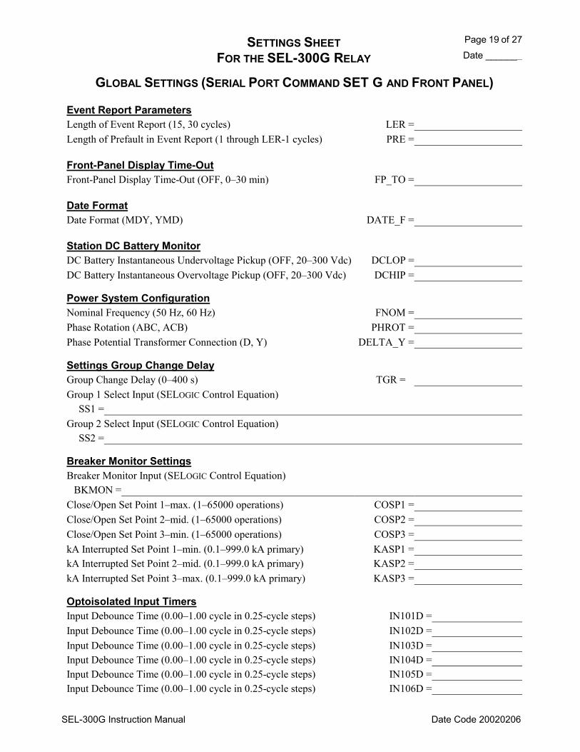
SETTINGS SHEET Page 19 of 27 FOR THE SEL-300G RELAY Date _______
SEL-300G Instruction Manual Date Code 20020206
GLOBAL SETTINGS (SERIAL PORT COMMAND SET G AND FRONT PANEL)
Event Report Parameters Length of Event Report (15, 30 cycles) LER = Length of Prefault in Event Report (1 through LER-1 cycles) PRE =
Front-Panel Display Time-Out Front-Panel Display Time-Out (OFF, 030 min) FP_TO =
Date Format Date Format (MDY, YMD) DATE_F =
Station DC Battery Monitor DC Battery Instantaneous Undervoltage Pickup (OFF, 20300 Vdc) DCLOP = DC Battery Instantaneous Overvoltage Pickup (OFF, 20300 Vdc) DCHIP =
Power System Configuration Nominal Frequency (50 Hz, 60 Hz) FNOM = Phase Rotation (ABC, ACB) PHROT = Phase Potential Transformer Connection (D, Y) DELTA_Y =
Settings Group Change Delay Group Change Delay (0400 s) TGR = Group 1 Select Input (SELOGIC Control Equation)
SS1 = Group 2 Select Input (SELOGIC Control Equation)
SS2 =
Breaker Monitor Settings Breaker Monitor Input (SELOGIC Control Equation)
BKMON = Close/Open Set Point 1max. (165000 operations) COSP1 = Close/Open Set Point 2mid. (165000 operations) COSP2 = Close/Open Set Point 3min. (165000 operations) COSP3 = kA Interrupted Set Point 1min. (0.1999.0 kA primary) KASP1 = kA Interrupted Set Point 2mid. (0.1999.0 kA primary) KASP2 = kA Interrupted Set Point 3max. (0.1999.0 kA primary) KASP3 =
Optoisolated Input Timers Input Debounce Time (0.001.00 cycle in 0.25-cycle steps) IN101D = Input Debounce Time (0.001.00 cycle in 0.25-cycle steps) IN102D = Input Debounce Time (0.001.00 cycle in 0.25-cycle steps) IN103D = Input Debounce Time (0.001.00 cycle in 0.25-cycle steps) IN104D = Input Debounce Time (0.001.00 cycle in 0.25-cycle steps) IN105D = Input Debounce Time (0.001.00 cycle in 0.25-cycle steps) IN106D =

Page 20 of 27 SETTINGS SHEET Date _______ FOR THE SEL-300G RELAY
SEL-300G Instruction Manual Date Code 20020206
GLOBAL SETTINGS (SERIAL PORT COMMAND SET G AND FRONT PANEL)
Optoisolated Input Timers for Model 0300G_1 Input IN201 Debounce Time (0.001.00 cycles in 0.25-cycle steps) IN201D = Input IN202 Debounce Time (0.001.00 cycles in 0.25-cycle steps) IN202D = Input IN203 Debounce Time (0.001.00 cycles in 0.25-cycle steps) IN203D = Input IN204 Debounce Time (0.001.00 cycles in 0.25-cycle steps) IN204D = Input IN205 Debounce Time (0.001.00 cycles in 0.25-cycle steps) IN205D = Input IN206 Debounce Time (0.001.00 cycles in 0.25-cycle steps) IN206D = Input IN207 Debounce Time (0.001.00 cycles in 0.25-cycle steps) IN207D = Input IN208 Debounce Time (0.001.00 cycles in 0.25-cycle steps) IN208D =
Local Bit Labels Enter the following characters:0-9, A-Z, -, /, ., space for each text label setting, subject to the specified character limit. Enter NA to null a label. Local Bit LB1 Name (14 characters) NLB1 =
Clear Local Bit LB1 Label (7 characters) (setting hidden if NLB1 = NA) CLB1 = Set Local Bit LB1 Label (7 characters) (setting hidden if NLB1 = NA) SLB1 = Pulse Local Bit LB1 Label (7 characters) (setting hidden if NLB1 = NA) PLB1 = Local Bit LB2 Name (14 characters) NLB2 = Clear Local Bit LB2 Label (7 characters) (setting hidden if NLB2 = NA) CLB2 = Set Local Bit LB2 Label (7 characters) (setting hidden if NLB2 = NA) SLB2 = Pulse Local Bit LB2 Label (7 characters) (setting hidden if NLB2 = NA) PLB2 = Local Bit LB3 Name (14 characters) NLB3 = Clear Local Bit LB3 Label (7 characters) (setting hidden if NLB3 = NA) CLB3 = Set Local Bit LB3 Label (7 characters) (setting hidden if NLB3 = NA) SLB3 = Pulse Local Bit LB3 Label (7 characters) (setting hidden if NLB3 = NA) PLB3 = Local Bit LB4 Name (14 characters) NLB4 = Clear Local Bit LB4 Label (7 characters) (setting hidden if NLB4 = NA) CLB4 = Set Local Bit LB4 Label (7 characters) (setting hidden if NLB4 = NA) SLB4 = Pulse Local Bit LB4 Label (7 characters) (setting hidden if NLB4 = NA) PLB4 = Local Bit LB5 Name (14 characters) NLB5 =

SETTINGS SHEET Page 21 of 27 FOR THE SEL-300G RELAY Date _______
SEL-300G Instruction Manual Date Code 20020206
GLOBAL SETTINGS (SERIAL PORT COMMAND SET G AND FRONT PANEL)
Clear Local Bit LB5 Label (7 characters) (setting hidden if NLB5 = NA) CLB5 = Set Local Bit LB5 Label (7 characters) (setting hidden if NLB5 = NA) SLB5 = Pulse Local Bit LB5 Label (7 characters) (setting hidden if NLB5 = NA) PLB5 = Local Bit LB6 Name (14 characters) NLB6 = Clear Local Bit LB6 Label (7 characters) (setting hidden if NLB6 = NA) CLB6 = Set Local Bit LB6 Label (7 characters) (setting hidden if NLB6 = NA) SLB6 = Pulse Local Bit LB6 Label (7 characters) (setting hidden if NLB6 = NA) PLB6 = Local Bit LB7 Name (14 characters) NLB7 = Clear Local Bit LB7 Label (7 characters) (setting hidden if NLB7 = NA) CLB7 = Set Local Bit LB7 Label (7 characters) (setting hidden if NLB7 = NA) SLB7 = Pulse Local Bit LB7 Label (7 characters) (setting hidden if NLB7 = NA) PLB7 = Local Bit LB8 Name (14 characters) NLB8 = Clear Local Bit LB8 Label (7 characters) (setting hidden if NLB8 = NA) CLB8 = Set Local Bit LB8 Label (7 characters) (setting hidden if NLB8 = NA) SLB8 = Pulse Local Bit LB8 Label (7 characters) (setting hidden if NLB8 = NA) PLB8 = Local Bit LB9 Name (14 characters) NLB9 = Clear Local Bit LB9 Label (7 characters) (setting hidden if NLB9 = NA) CLB9 = Set Local Bit LB9 Label (7 characters) (setting hidden if NLB9 = NA) SLB9 = Pulse Local Bit LB9 Label (7 characters) (setting hidden if NLB9 = NA) PLB9 = Local Bit LB10 Name (14 characters) NLB10 = Clear Local Bit LB10 Label (7 characters) (setting hidden if NLB10 = NA) CLB10 = Set Local Bit LB10 Label (7 characters) (setting hidden if NLB10 = NA) SLB10 = Pulse Local Bit LB10 Label (7 characters) (setting hidden if NLB10 = NA) PLB10 = Local Bit LB11 Name (14 characters) NLB11 = Clear Local Bit LB11 Label (7 characters) CLB11 =

Page 22 of 27 SETTINGS SHEET Date _______ FOR THE SEL-300G RELAY
SEL-300G Instruction Manual Date Code 20020206
GLOBAL SETTINGS (SERIAL PORT COMMAND SET G AND FRONT PANEL)
(setting hidden if NLB11 = NA) Set Local Bit LB11 Label (7 characters) (setting hidden if NLB11 = NA) SLB11 = Pulse Local Bit LB11 Label (7 characters) (setting hidden if NLB11 = NA) PLB11 = Local Bit LB12 Name (14 characters) NLB12 = Clear Local Bit LB12 Label (7 characters) (setting hidden if NLB12 = NA) CLB12 = Set Local Bit LB12 Label (7 characters) (setting hidden if NLB12 = NA) SLB12 = Pulse Local Bit LB12 Label (7 characters) (setting hidden if NLB12 = NA) PLB12 = Local Bit LB13 Name (14 characters) NLB13 = Clear Local Bit LB13 Label (7 characters) (setting hidden if NLB13 = NA) CLB13 = Set Local Bit LB13 Label (7 characters) (setting hidden if NLB13 = NA) SLB13 = Pulse Local Bit LB13 Label (7 characters) (setting hidden if NLB13 = NA) PLB13 = Local Bit LB14 Name (14 characters) NLB14 = Clear Local Bit LB14 Label (7 characters) (setting hidden if NLB14 = NA) CLB14 = Set Local Bit LB14 Label (7 characters) (setting hidden if NLB14 = NA) SLB14 = Pulse Local Bit LB14 Label (7 characters) (setting hidden if NLB14 = NA) PLB14 = Local Bit LB15 Name (14 characters) NLB15 = Clear Local Bit LB15 Label (7 characters) (setting hidden if NLB15 = NA) CLB15 = Set Local Bit LB15 Label (7 characters) (setting hidden if NLB15 = NA) SLB15 = Pulse Local Bit LB15 Label (7 characters) (setting hidden if NLB15 = NA) PLB15 = Local Bit LB16 Name (14 characters) NLB16 = Clear Local Bit LB16 Label (7 characters) (setting hidden if NLB16 = NA) CLB16 = Set Local Bit LB16 Label (7 characters) (setting hidden if NLB16 = NA) SLB16 = Pulse Local Bit LB16 Label (7 characters) (setting hidden if NLB16 = NA) PLB16 =
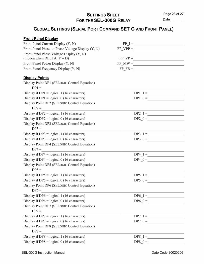
SETTINGS SHEET Page 23 of 27 FOR THE SEL-300G RELAY Date _______
SEL-300G Instruction Manual Date Code 20020206
GLOBAL SETTINGS (SERIAL PORT COMMAND SET G AND FRONT PANEL)
Front-Panel Display Front-Panel Current Display (Y, N) FP_I = Front-Panel Phase-to-Phase Voltage Display (Y, N) FP_VPP = Front-Panel Phase Voltage Display (Y, N) (hidden when DELTA_Y = D) FP_VP = Front-Panel Power Display (Y, N) FP_MW = Front-Panel Frequency Display (Y, N) FP_FR =
Display Points Display Point DP1 (SELOGIC Control Equation)
DP1 = Display if DP1 = logical 1 (16 characters) DP1_1 = Display if DP1 = logical 0 (16 characters) DP1_0 = Display Point DP2 (SELOGIC Control Equation)
DP2 = Display if DP2 = logical 1 (16 characters) DP2_1 = Display if DP2 = logical 0 (16 characters) DP2_0 = Display Point DP3 (SELOGIC Control Equation)
DP3 = Display if DP3 = logical 1 (16 characters) DP3_1 = Display if DP3 = logical 0 (16 characters) DP3_0 = Display Point DP4 (SELOGIC Control Equation)
DP4 = Display if DP4 = logical 1 (16 characters) DP4_1 = Display if DP4 = logical 0 (16 characters) DP4_0 = Display Point DP5 (SELOGIC Control Equation)
DP5 = Display if DP5 = logical 1 (16 characters) DP5_1 = Display if DP5 = logical 0 (16 characters) DP5_0 = Display Point DP6 (SELOGIC Control Equation)
DP6 = Display if DP6 = logical 1 (16 characters) DP6_1 = Display if DP6 = logical 0 (16 characters) DP6_0 = Display Point DP7 (SELOGIC Control Equation)
DP7 = Display if DP7 = logical 1 (16 characters) DP7_1 = Display if DP7 = logical 0 (16 characters) DP7_0 = Display Point DP8 (SELOGIC Control Equation)
DP8 = Display if DP8 = logical 1 (16 characters) DP8_1 = Display if DP8 = logical 0 (16 characters) DP8_0 =
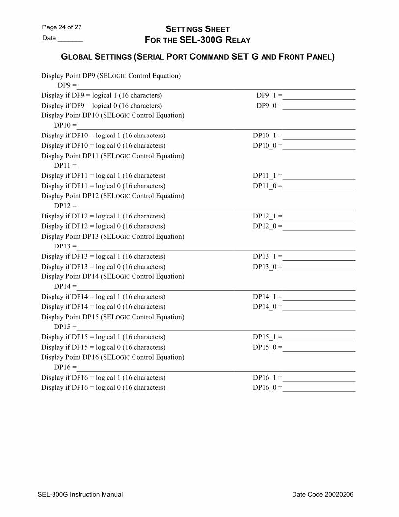
Page 24 of 27 SETTINGS SHEET Date _______ FOR THE SEL-300G RELAY
SEL-300G Instruction Manual Date Code 20020206
GLOBAL SETTINGS (SERIAL PORT COMMAND SET G AND FRONT PANEL)
Display Point DP9 (SELOGIC Control Equation) DP9 =
Display if DP9 = logical 1 (16 characters) DP9_1 = Display if DP9 = logical 0 (16 characters) DP9_0 = Display Point DP10 (SELOGIC Control Equation)
DP10 = Display if DP10 = logical 1 (16 characters) DP10_1 = Display if DP10 = logical 0 (16 characters) DP10_0 = Display Point DP11 (SELOGIC Control Equation)
DP11 = Display if DP11 = logical 1 (16 characters) DP11_1 = Display if DP11 = logical 0 (16 characters) DP11_0 = Display Point DP12 (SELOGIC Control Equation)
DP12 = Display if DP12 = logical 1 (16 characters) DP12_1 = Display if DP12 = logical 0 (16 characters) DP12_0 = Display Point DP13 (SELOGIC Control Equation)
DP13 = Display if DP13 = logical 1 (16 characters) DP13_1 = Display if DP13 = logical 0 (16 characters) DP13_0 = Display Point DP14 (SELOGIC Control Equation)
DP14 = Display if DP14 = logical 1 (16 characters) DP14_1 = Display if DP14 = logical 0 (16 characters) DP14_0 = Display Point DP15 (SELOGIC Control Equation)
DP15 = Display if DP15 = logical 1 (16 characters) DP15_1 = Display if DP15 = logical 0 (16 characters) DP15_0 = Display Point DP16 (SELOGIC Control Equation)
DP16 = Display if DP16 = logical 1 (16 characters) DP16_1 = Display if DP16 = logical 0 (16 characters) DP16_0 =
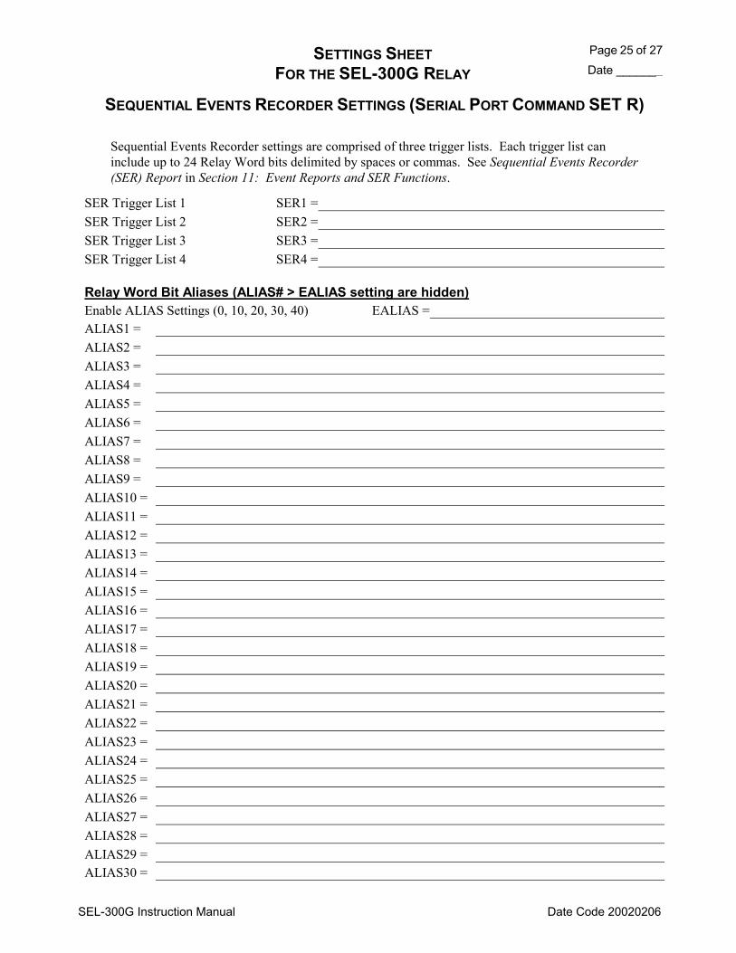
SETTINGS SHEET Page 25 of 27 FOR THE SEL-300G RELAY Date _______
SEL-300G Instruction Manual Date Code 20020206
SEQUENTIAL EVENTS RECORDER SETTINGS (SERIAL PORT COMMAND SET R)
Sequential Events Recorder settings are comprised of three trigger lists. Each trigger list can include up to 24 Relay Word bits delimited by spaces or commas. See Sequential Events Recorder (SER) Report in Section 11: Event Reports and SER Functions.
SER Trigger List 1 SER1 = SER Trigger List 2 SER2 = SER Trigger List 3 SER3 = SER Trigger List 4 SER4 =
Relay Word Bit Aliases (ALIAS# > EALIAS setting are hidden) Enable ALIAS Settings (0, 10, 20, 30, 40) EALIAS = ALIAS1 = ALIAS2 = ALIAS3 = ALIAS4 = ALIAS5 = ALIAS6 = ALIAS7 = ALIAS8 = ALIAS9 = ALIAS10 = ALIAS11 = ALIAS12 = ALIAS13 = ALIAS14 = ALIAS15 = ALIAS16 = ALIAS17 = ALIAS18 = ALIAS19 = ALIAS20 = ALIAS21 = ALIAS22 = ALIAS23 = ALIAS24 = ALIAS25 = ALIAS26 = ALIAS27 = ALIAS28 = ALIAS29 = ALIAS30 =
Page 26 of 27 SETTINGS SHEET Date _______ FOR THE SEL-300G RELAY
SEL-300G Instruction Manual Date Code 20020206
SEQUENTIAL EVENTS RECORDER SETTINGS (SERIAL PORT COMMAND SET R)
ALIAS31 = ALIAS32 = ALIAS33 = ALIAS34 = ALIAS35 = ALIAS36 = ALIAS37 = ALIAS38 = ALIAS39 = ALIAS40 =

SETTINGS SHEET Page 27 of 27 FOR THE SEL-300G RELAY Date _______
SEL-300G Instruction Manual Date Code 20020206
PORT SETTINGS (SERIAL PORT COMMAND SET P AND FRONT PANEL)
Protocol Settings Protocol (SEL, LMD, MOD) PROTO = LMD Prefix (@, #, $, %, &) PREFIX = LMD Address (0199) ADDR = LMD Settling Time (030 seconds) SETTLE = Enable Hardware Handshaking (Y, N, H) RTSCTS = Modbus® Slave ID (1247) SLAVEID =
Protocol Settings: Set PROTO = SEL for standard SEL ASCII protocol. For SEL Distributed Port Switch Protocol (LMD), set PROTO = LMD. Refer to Appendix C: SEL Distributed Port Switch Protocol for details on the LMD protocol. PREFIX, ADDR, and SETTLE settings are only active if PROTOCOL = LMD. The settings are hidden if PROTO = SEL or MOD. For Modbus RTU protocol (MOD), set PROTO = MOD. Refer to Appendix F: Modbus® RTU Communications Protocol for details. SLAVID and RTSCTS settings are only active if PROTO = MOD. These settings are hidden if PROTO = SEL or LMD.
Communications Settings Baud Rate (300, 1200, 2400, 4800, 9600, 19200, 38400) SPEED =
Note: The highest baud rate for Modbus RTU protocol is 19200 Data Bits (7, 8) BITS = Parity (0, E, N) Odd, Even, None PARITY = Stop Bits (1, 2) STOP =
Other Port Settings Time-Out (030 minutes) T_OUT = Send Auto Messages to Port (Y, N) AUTO = Enable Hardware Handshaking (Y, N) RTSCTS = Fast Operate Enable (Y, N) FASTOP =
Other Port Settings. Set T_OUT to the number of minutes of serial port inactivity for an automatic log out. Set T_OUT = 0 for no port time-out.
Set AUTO = Y to allow automatic messages at the serial port. Set RTSCTS = Y to enable hardware handshaking. With RTSCTS = Y, the relay will not send characters until the CTS input is asserted. Also, if the relay is unable to receive characters, it deasserts the RTS line. Setting RTSCTS is hidden when PROTO = LMD.
Set FASTOP = Y to enable binary Fast Operate messages at the serial port. Set FASTOP = N to block binary Fast Operate messages. Refer to Appendix D: Configuration, Fast Meter, and Fast Operate Commands for the description of the SEL-300G Relay Fast Operate commands.

SEL-300G Instruction Manual Date Code 20020206
TABLE OF CONTENTS
SECTION 7: RELAY COMMISSIONING.............................................7-1
Introduction ...................................................................................................................................7-1 Commissioning Testing Philosophy .............................................................................................7-1 Testing Methods and Tools...........................................................................................................7-1
Test Features Provided by the Relay.....................................................................................7-1 Low-Level Test Interface ......................................................................................................7-2 Test Methods.........................................................................................................................7-4
Testing Via Front-Panel Indicators ...............................................................................7-4 Testing Via Output Contacts .........................................................................................7-4 Testing Via Sequential Events Recorder.......................................................................7-5
Relay Commissioning Procedure ..................................................................................................7-6 Introduction ...........................................................................................................................7-6 Required Equipment..............................................................................................................7-6 Commissioning Procedure ....................................................................................................7-7
Protection Element Tests ............................................................................................................7-18 Introduction .........................................................................................................................7-18 Three Voltage Source and Three Current Source Connections ..........................................7-18 Phase Distance (21) Element...............................................................................................7-19
Equipment Needed ......................................................................................................7-19 Test Source Connections .............................................................................................7-19 Basic Element Operation.............................................................................................7-19 Element Pickup Accuracy Test ...................................................................................7-21 Element Timing Accuracy Test...................................................................................7-25
21P1D Time-Delay Accuracy Test......................................................................7-25 Volts/Hertz (24) Element ....................................................................................................7-26
Equipment Needed ......................................................................................................7-26 Test Source Connections .............................................................................................7-26 Basic Element Operation.............................................................................................7-26 Element Pickup Accuracy Test ...................................................................................7-27 Element Timing Accuracy Test...................................................................................7-29
24D1D Time-Delay Accuracy Test .....................................................................7-29 24C2 Time-Delay Accuracy Test, 24CCS = DD.................................................7-30 24C2 Time-Delay Accuracy Test, 24CCS = I .....................................................7-32 24C2 Time-Delay Accuracy Test, 24CCS = ID ..................................................7-35
Synchronism Checking (25) Function.................................................................................7-38 Equipment Needed ......................................................................................................7-38 Test Source Connections .............................................................................................7-38 Basic Element Operation.............................................................................................7-38 Voltage Element Accuracy Test..................................................................................7-39 Slip Frequency Accuracy Test ....................................................................................7-44 Static Phase Angle Accuracy Test...............................................................................7-45
Undervoltage (27) Elements................................................................................................7-47 Equipment Needed ......................................................................................................7-47 Test Source Connections .............................................................................................7-47 Basic Element Operation.............................................................................................7-47
Relay Commissioning
Date Code 20020206 SEL-300G Instruction Manual
ii
Element Pickup Accuracy Test ...................................................................................7-47 Reverse/Low-Forward Power (32) Element........................................................................7-49
Equipment Needed ......................................................................................................7-49 Test Source Connections .............................................................................................7-49 Basic Element Operation.............................................................................................7-49 Element Operating Accuracy Test, DELTA_Y = Y ...................................................7-49 Element Operating Accuracy Test, DELTA_Y = D ...................................................7-52 Element Timing Accuracy Test...................................................................................7-54
32 Element Definite-Time Delay Accuracy Test ................................................7-54 Loss-of-Field (40) Element .................................................................................................7-55
Equipment Needed ......................................................................................................7-55 Test Source Connections .............................................................................................7-55 Basic Element Operation.............................................................................................7-55 Element Operating Accuracy Test...............................................................................7-56 Element Timing Accuracy Test...................................................................................7-62
40 Element Definite-Time Delay Accuracy Test ................................................7-62 Negative-Sequence Overcurrent (46) Element....................................................................7-63
Equipment Needed ......................................................................................................7-63 Test Source Connections .............................................................................................7-63 Basic Element Operation.............................................................................................7-63 Element Pickup Accuracy Test ...................................................................................7-64 Element Timing Accuracy Test...................................................................................7-65
46Q1D Time-Delay Accuracy Test .....................................................................7-66 46Q2 Inverse-Time Accuracy Test......................................................................7-66
Overcurrent (50/51) Elements.............................................................................................7-68 Equipment Needed ......................................................................................................7-68 Test Source Connections .............................................................................................7-68 Basic Element Operation.............................................................................................7-68 Element Pickup Accuracy Test ...................................................................................7-68 Element Timing Accuracy Test...................................................................................7-69
Definite Time-Delay Accuracy Test....................................................................7-69 Inverse-Time Accuracy Test................................................................................7-70
Voltage Controlled Time-Overcurrent (51C) Element .......................................................7-71 Equipment Needed ......................................................................................................7-71 Test Source Connections .............................................................................................7-71 Basic Element Operation.............................................................................................7-72 Element Pickup Accuracy Test ...................................................................................7-72 Element Timing Accuracy Test...................................................................................7-74
Inverse-Time Accuracy Test................................................................................7-74 Voltage Restrained Time-Overcurrent (51V) Element .......................................................7-75
Equipment Needed ......................................................................................................7-75 Test Source Connections .............................................................................................7-75 Basic Element Operation.............................................................................................7-75 Element Pickup Accuracy Test ...................................................................................7-76 Element Timing Accuracy Test...................................................................................7-78
Inverse-Time Accuracy Test................................................................................7-78 Overvoltage (59) Elements..................................................................................................7-80
Equipment Needed ......................................................................................................7-80 Test Source Connections .............................................................................................7-80 Basic Element Operation.............................................................................................7-81

Relay Commissioning iii
SEL-300G Instruction Manual Date Code 20020206
Element Pickup Accuracy Test ...................................................................................7-81 100% Stator Ground (64) Element......................................................................................7-82
Equipment Needed ......................................................................................................7-82 Basic Element Operation.............................................................................................7-82
64G1 Element Operation .....................................................................................7-82 64G2 Element Operation, 64RAT ≠ 0.................................................................7-82 64G2 Element Operation, 64RAT = 0.................................................................7-83
64G1 Element Operating Accuracy Test.....................................................................7-83 64G1 Element Timing Accuracy Test .........................................................................7-84 64G2 Element Operating Accuracy Test, 64RAT ≠ 0 ................................................7-85 64G2 Element Timing Accuracy Test, 64RAT ≠ 0.....................................................7-87 64G2 Element Operating Accuracy Test, 64RAT = 0 ................................................7-87 64G2 Element Timing Accuracy Test, 64RAT = 0.....................................................7-89
Out-of-Step (78) ElementSingle Blinder...........................................................................7-90 Equipment Needed ......................................................................................................7-90 Test Source Connections .............................................................................................7-90 Basic Element Operation.............................................................................................7-90 78Z1 Element Operating Accuracy Test .....................................................................7-91 78R1 Element (Right Blinder) Operating Accuracy Test ...........................................7-93 78R2 Element (Left Blinder) Operating Accuracy Test .............................................7-94
Out-of-Step (78) ElementDouble Blinder .........................................................................7-95 Equipment Needed ......................................................................................................7-95 Test Source Connections .............................................................................................7-95 Basic Element Operation.............................................................................................7-95
Over/underfrequency (81) Elements ...................................................................................7-96 Equipment Needed ......................................................................................................7-96 Test Source Connections .............................................................................................7-96 Basic Element Operation.............................................................................................7-96 Element Pickup Accuracy Test ...................................................................................7-97 Element Timing Accuracy Test...................................................................................7-98
81DnD Time-Delay Accuracy Test .....................................................................7-98 Ground Differential (87N) Element ....................................................................................7-99
Equipment Needed ......................................................................................................7-99 Test Source Connections .............................................................................................7-99 Basic Element Operation...........................................................................................7-100 Element Pickup Accuracy Test .................................................................................7-101 Element Timing Accuracy Test.................................................................................7-103
87N1D Time-Delay Accuracy Test ...................................................................7-103 Current Differential (87) Elements ...................................................................................7-103
Equipment Needed ....................................................................................................7-103 Basic Element Operation...........................................................................................7-104 U87P Unrestrained Element Operating Accuracy Test.............................................7-104 O87P Restrained Element Pickup Accuracy Test .....................................................7-106 SLP1 Restrained Element Accuracy Test .................................................................7-107 SLP2 Restrained Element Accuracy Test .................................................................7-109 PCT2 Second-Harmonic Blocking Accuracy Test ....................................................7-110
Differential Element Commissioning Worksheet .....................................................................7-112 Check List .........................................................................................................................7-113
Relay Commissioning
Date Code 20020206 SEL-300G Instruction Manual
iv
TABLES Table 7.1: ... Communication Cables to Connect the SEL-300G Relayto Other Devices .......................7-10 Table 7.2: ... SET Command Editing Keystrokes ....................................................................................7-12 Table 7.3: ... SEL-300G Relay Contact I/O Viewed by the TAR Command ..........................................7-15 Table 7.4: ... Serial Port Commands That Clear Relay Data Buffers ......................................................7-17 Table 7.5: ... Relay Word Row 39 Shows Relay Word Bits for Distance Elements ...............................7-24 Table 7.6: ... Relay Word Row 2 Shows Relay Word Bits for Volts/Hertz Elements.............................7-28 Table 7.7: ... Synch-Check Element Test Voltage Phase Angles.............................................................7-40 Table 7.8: ... Relay Word Row 36 Shows Relay Word Bits for Synch-Check Elements ........................7-43 Table 7.9: ... Relay Word Row 37 Shows Relay Word Bits for Slip Frequency Elements .....................7-45 Table 7.10: . Relay Word Row 36 Shows Relay Word Bits for Angle Elements....................................7-46 Table 7.11: . Reverse Power Element Test Signal Summary...................................................................7-50 Table 7.12: . Relay Word Row 4 Shows Relay Word Bits for Reverse/Low-Forward Power
Elements .......................................................................................................................7-51 Table 7.13: . Relay Word Row 5 Shows Relay Word Bits for Loss-of-Field Elements..........................7-58 Table 7.14: . Relay Word Row 6 Shows Relay Word Bits for Negative-Sequence Overcurrent
Elements .......................................................................................................................7-65 Table 7.15: . Relay Word Row 7 Shows Relay Word Bits for Voltage Controlled Time-
Overcurrent Elements ...................................................................................................7-73 Table 7.16: . Relay Word Row 9 Shows Relay Word Bits for the Voltage Restrained Time-
Overcurrent Elements ...................................................................................................7-77 Table 7.17: . Relay Word Row 12 Shows Relay Word Bits for 64G Elements.......................................7-84 Table 7.18: . Relay Word Row 14 Shows Relay Word Bits for Frequency Elements.............................7-98 Table 7.19: . Relay Word Row 38 Shows Relay Word Bits for Ground Differential Elements ...........7-102 Table 7.20: . Test Current Adjustment Factors For Testing ..................................................................7-105 Table 7.21: . Relay Word Row 34 Shows Relay Word Bits for 87U Elements.....................................7-105 Table 7.22: . Relay Word Row 33 Shows Relay Word Bits for 87R Elements.....................................7-107
FIGURES Figure 7.1: .. Low-Level Test Interface, 0300G0.......................................................................................7-3 Figure 7.2: .. Low-Level Test Interface, 0300G1.......................................................................................7-3 Figure 7.3: .. Low-Level Test Interface, 0300G2.......................................................................................7-3 Figure 7.4: .. Low-Level Test Interface, 0300G3.......................................................................................7-3 Figure 7.5: .. Relay Commissioning Flowchart (refer to text for detailed instructions) ............................7-7 Figure 7.6: .. DC Supply Polarity, Continuity Checks ...............................................................................7-8 Figure 7.7: .. Three-Phase AC Connection Test Voltage Signals ............................................................7-13 Figure 7.8: .. Open-Delta AC Potential Connection Test Voltage Signals ..............................................7-14 Figure 7.9: .. Three Voltage Source and Three Current Source Test Connections..................................7-18 Figure 7.10: Two Voltage Source and Three Current Source Test Connections....................................7-19 Figure 7.11: Generator Voltage and Current Relationships During a System Phase-to-Phase Fault......7-20 Figure 7.12: Generator Voltage and Current Relationships During a System Three-Phase Fault ..........7-21 Figure 7.13: 24C2 Time-Delay Test Points, 24CCS = DD .....................................................................7-30 Figure 7.14: 24C2 Time-Delay Test Points, 24CCS = I..........................................................................7-33 Figure 7.15: 24C2 Time-Delay Test Points, 24CCS = ID.......................................................................7-35 Figure 7.16: 32Pn Element Operate Region Depends on the Sign of the 32Pn Setting..........................7-51 Figure 7.17: Loss-of-Field Element Diameter and Offset Tests, 40XD2 < 0 .........................................7-57
Relay Commissioning v
SEL-300G Instruction Manual Date Code 20020206
Figure 7.18: Loss-of-Field Element Diameter Test, 40XDn > 0.............................................................7-57 Figure 7.19: Loss-of-Field Element Off-Diameter Test, 40XDn < 0......................................................7-61 Figure 7.20: Single Current Source Test Connection..............................................................................7-63 Figure 7.21: 46Q2 Inverse-Time Element Test .......................................................................................7-67 Figure 7.22: Three Voltage Sources and One Current Source Test Connections (DELTA_Y = Y) ......7-71 Figure 7.23: Two Voltage Sources and One Current Source Test Connections (DELTA_Y = D) ........7-72 Figure 7.24: One Voltage Source Test Connection (DELTA_Y = Y)....................................................7-80 Figure 7.25: One Voltage Source Test Connection (DELTA_Y = D)....................................................7-81 Figure 7.26: Neutral Voltage Test Connection, 64G1.............................................................................7-83 Figure 7.27: 64G2 Element Test Connections, 64RAT ≠ 0 ....................................................................7-85 Figure 7.28: 64G2 Element Test Connections, 64RAT = 0 (DELTA_Y = D) .......................................7-88 Figure 7.29: Out-of-Step Single Blinder Element, Diameter and Blinder Tests.....................................7-92 Figure 7.30: Out-of-Step Double Blinder Element, Diameter and Blinder Tests ...................................7-96 Figure 7.31: 87N Test Connections.......................................................................................................7-100 Figure 7.32: Percentage Restraint Differential Characteristic ..............................................................7-104 Figure 7.33: Test Connections for Parallel Current Sources.................................................................7-111


Relay Commissioning 7-1
SEL-300G Instruction Manual Date Code 20000616
SECTION 7: RELAY COMMISSIONING
INTRODUCTION This section provides guidelines for commissioning and testing the SEL-300G Relay. Included are discussions on testing philosophies, methods, and tools, plus detailed test procedures for selected protection functions.
COMMISSIONING TESTING PHILOSOPHY Commissioning testing is performed when a protective relay is installed to:
a) Ensure that all system ac and dc connections are correct. b) Ensure that the relay functions as intended using your settings. c) Ensure that all auxiliary equipment operates as intended.
To satisfy these requirements, check all connected or monitored inputs and outputs, verify polarity and phase rotation of ac connections, and perform a simple check of protection elements.
SEL performs a complete functional check and calibration of each relay before it is shipped. This helps ensure that you receive a relay that operates correctly and accurately. Commissioning tests should verify that the relay is properly connected to the power system and all auxiliary equipment. Verify control signal inputs and outputs. Check breaker auxiliary inputs, SCADA control inputs, and monitoring outputs. Use an ac connection check to verify that the relay current and voltage inputs are of the proper magnitude and phase rotation.
Brief fault tests ensure that the relay settings are correct. It is not necessary to test every relay element, timer, and function in these tests.
At commissioning time, use the relay METER command to verify the ac current and voltage magnitude and phase rotation. Use the PULSE command to verify relay output contact operation. Use the TARGET command to verify optoisolated input operation.
TESTING METHODS AND TOOLS
Test Features Provided by the Relay
The following features assist you during relay testing.
METER Command
The METER command shows the ac currents and voltages (magnitude and phase angle) presented to the relay in primary values. In addition, the command shows power system frequency (FREQ) and the voltage input to the relay power supply terminals (VDC). Compare these quantities against other devices of known accuracy. The METER command is available at the serial ports and front-panel display. See Section 9: Front-Panel Operation and Section 10: Serial Port Communications and Commands.
Relay Commissioning
Date Code 20000616 SEL-300G Instruction Manual
7-2
EVENT Command
The relay generates a 15- or 30-cycle event report in response to faults or disturbances. Each report contains current and voltage information, relay element states, and input/output contact information. If you question the relay response or your test method, use the event report for more information. The EVENT command is available at the serial ports. See Section 11: Event Reports and SER Functions.
SER Command
The relay provides a Sequential Events Recorder (SER) event report that time-tags changes in relay element and input/output contact states. The SER provides a convenient means to verify the pickup/dropout of any element in the relay. The SER command is available at the serial ports. See Section 11: Event Reports and SER Functions.
TARGET Command
Use the TARGET command to view the state of relay control inputs, relay outputs, and relay elements during a test. The TARGET command is available at the serial ports and the front panel. See Section 10: Serial Port Communications and Commands and Section 9: Front-Panel Operation.
PULSE Command
Use the PULSE command to test the contact output circuits. The PULSE command is available at the serial ports and the front panel. See Section 10: Serial Port Communications and Commands and Section 9: Front-Panel Operation.
Low-Level Test Interface
The SEL-300G Relay has a low-level test interface between the calibrated input module and the separately-calibrated processing module. You may test the relay in either of two ways: conventionally, by applying ac current and voltage signals to the relay inputs or by applying low magnitude ac voltage signals to the low-level test interface. Access the test interface by removing the relay front panel.
Figure 7.1 through Figure 7.4 show the low-level interface connections. This drawing also appears on the inside of the relay front panel. Remove the ribbon cable between the two modules to access the outputs of the input module and the inputs to the processing module (relay main board).
You can test the relay processing module using signals from the SEL-RTS Low-Level Relay Test System. Never apply voltage signals greater than 9 volts peak-to-peak to the low-level test interface. Figure 7.1 through Figure 7.4 show the signal scaling factors.
CAUTION !
The relay contains devices sensitive to Electrostatic Discharge (ESD). When working on the relay with front or top cover removed, work surfaces and personnel must be properly grounded or equipment damage may result.
You can test the input module two different ways:
1. Measure the outputs from the input module with an accurate voltmeter (measure signal pin to GND pin), and compare the readings to accurate instruments in the relay input circuits, or
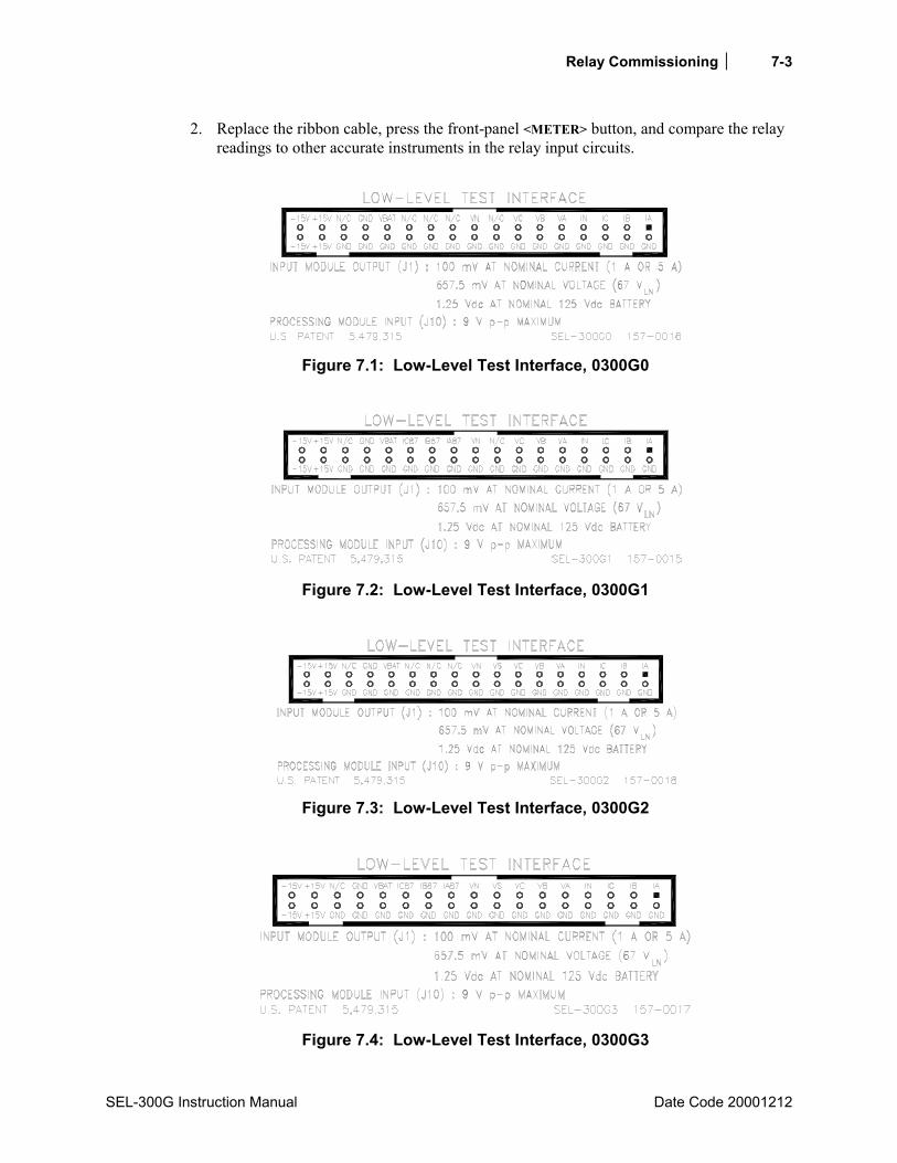
Relay Commissioning 7-3
SEL-300G Instruction Manual Date Code 20001212
2. Replace the ribbon cable, press the front-panel <METER> button, and compare the relay readings to other accurate instruments in the relay input circuits.
Figure 7.1: Low-Level Test Interface, 0300G0
Figure 7.2: Low-Level Test Interface, 0300G1
Figure 7.3: Low-Level Test Interface, 0300G2
Figure 7.4: Low-Level Test Interface, 0300G3
Relay Commissioning
Date Code 20000616 SEL-300G Instruction Manual
7-4
Test Methods
Test the pickup and dropout of relay elements using one of three methods: target command indication, output contact closure, or Sequential Events Recorder (SER).
The examples below show the settings necessary to route the phase time-overcurrent element 51PT to the output contacts and the SER. The 51PT element, like many in the SEL-300G Relay, is controlled by enable settings and/or torque-control settings. To enable the 51PT element, set the E51 enable setting and 51PTC torque-control setting to the following:
• E51 = Y (via the SET command) • 51PTC = 1 (set directly to logical 1, via the SET command)
Testing Via Front-Panel Indicators
Display the state of relay elements, inputs, and outputs using the front-panel or serial port TAR commands. Use this method to verify the pickup settings of protection elements.
Access the front-panel TAR command from the front-panel OTHER pushbutton menu. To display the state of the 51PT element on the front-panel display, press the OTHER pushbutton, cursor to the TAR option, and press SELECT. Press the Down arrow pushbutton until TAR 7 is displayed on the top row of the LCD. The bottom row of the LCD displays all elements asserted in Relay Word Row 7. The relay maps the state of the elements in Relay Word Row 7 on the bottom row of LEDs. The 51PT element state is reflected on the LED labeled 32. See Table 4.6 for the correspondence between the Relay Word elements and the TAR command.
To view the 51PT element status from the serial port, issue the TAR 51PT command. The relay will display the state of all elements in the Relay Word row containing the 51PT element.
Review TAR command descriptions in Section 10: Serial Port Communications and Commands and Section 9: Front-Panel Operation for further details on displaying element status via the TAR commands.
Testing Via Output Contacts
You can set the relay to operate an output contact for testing a single element. Use the SET command to set an output contact to close when the element under test asserts. The available elements are the Relay Word bits referenced in Table 4.6.
This method is useful for testing inverse-time elements like the 24C2T, 46Q2T, and 51VT elements.
For instance, the Access Level 2 command sequence below causes the relay to close output contact OUT106 when the 24C2T element asserts:
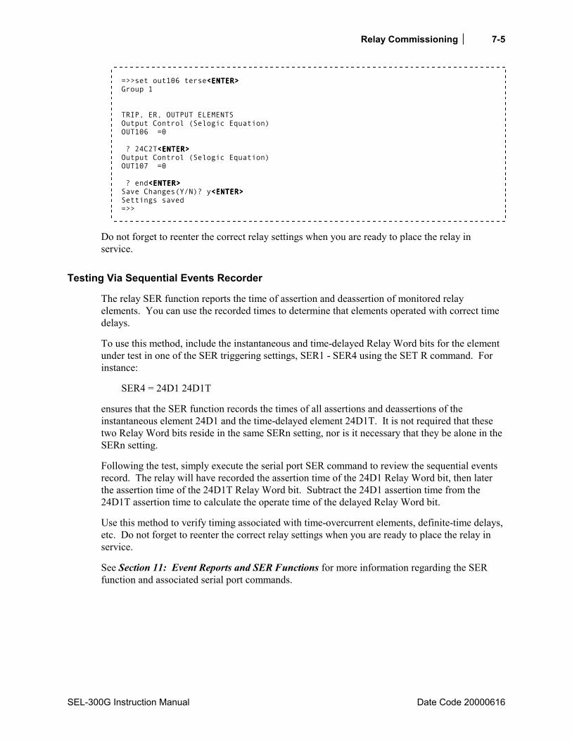
Relay Commissioning 7-5
SEL-300G Instruction Manual Date Code 20000616
=>>set out106 terse<ENTER><ENTER><ENTER><ENTER> Group 1 TRIP, ER, OUTPUT ELEMENTS Output Control (Selogic Equation) OUT106 =0 ? 24C2T<ENTER><ENTER><ENTER><ENTER> Output Control (Selogic Equation) OUT107 =0 ? end<ENTER><ENTER><ENTER><ENTER> Save Changes(Y/N)? y<ENTER><ENTER><ENTER><ENTER> Settings saved =>>
Do not forget to reenter the correct relay settings when you are ready to place the relay in service.
Testing Via Sequential Events Recorder
The relay SER function reports the time of assertion and deassertion of monitored relay elements. You can use the recorded times to determine that elements operated with correct time delays.
To use this method, include the instantaneous and time-delayed Relay Word bits for the element under test in one of the SER triggering settings, SER1 - SER4 using the SET R command. For instance:
SER4 = 24D1 24D1T
ensures that the SER function records the times of all assertions and deassertions of the instantaneous element 24D1 and the time-delayed element 24D1T. It is not required that these two Relay Word bits reside in the same SERn setting, nor is it necessary that they be alone in the SERn setting.
Following the test, simply execute the serial port SER command to review the sequential events record. The relay will have recorded the assertion time of the 24D1 Relay Word bit, then later the assertion time of the 24D1T Relay Word bit. Subtract the 24D1 assertion time from the 24D1T assertion time to calculate the operate time of the delayed Relay Word bit.
Use this method to verify timing associated with time-overcurrent elements, definite-time delays, etc. Do not forget to reenter the correct relay settings when you are ready to place the relay in service.
See Section 11: Event Reports and SER Functions for more information regarding the SER function and associated serial port commands.

Relay Commissioning
Date Code 20000616 SEL-300G Instruction Manual
7-6
RELAY COMMISSIONING PROCEDURE
Introduction
The procedure below is intended to help you enter settings into an SEL-300G Relay and verify that the SEL-300G Relay is properly connected. Steps later in the procedure call for operation of the protected generator at no load, light load, and full load to verify ac connections and take measurements for calculation of 100% stator ground fault protection elements.
CAUTION !
Be sure to follow the generator and prime mover manufacturers guidelines with respect to generator operation and commissioning.
This procedure is intended for use at initial relay installation and should not need to be repeated in the life of the relay unless major changes are made to the relay electrical connections.
This procedure is intended as a guideline. Modify this procedure as necessary to conform with your standard practices and the operating and commissioning guidelines published by the generator and prime mover manufacturers.
Required Equipment
• SEL-300G Relay, installed and connected according to your protection design. • PC with serial port, terminal emulation software, and serial communication cable (for
relay setting entry). • SEL-300G Relay Settings Sheets, filled out with settings appropriate to your generator
protection application and protection cabinet design. • AC and DC elementary schematics and wiring diagrams for this relay installation. • Continuity tester. • DC voltmeter. • Protective relay ac test source:
Minimum: Single-phase voltage plus single-phase current with ability to control phase angle between signals.
Preferred: Two- or three-phase voltage plus three-phase current with ability to control phase angle between signals.
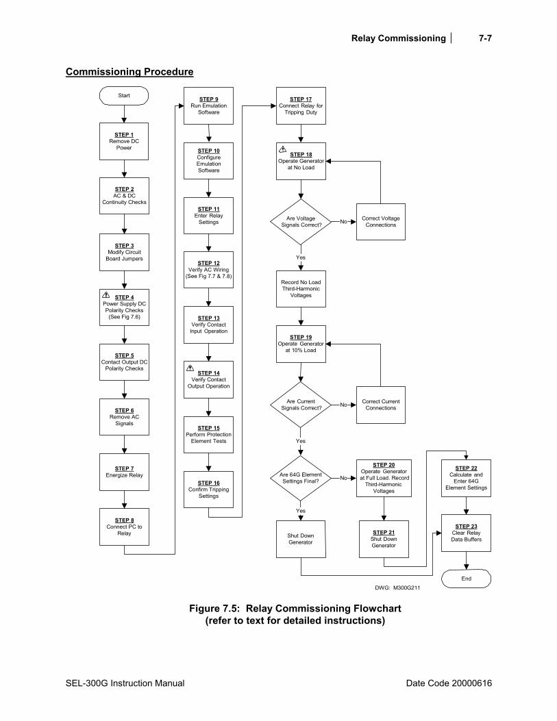
Relay Commissioning 7-7
SEL-300G Instruction Manual Date Code 20000616
Commissioning Procedure
DWG: M300G211
Correct VoltageConnections
STEP 17Connect Relay for
Tripping Duty
STEP 18Operate Generator
at No Load
STEP 19Operate Generator
at 10% Load
Are Voltage Signals Correct?
Record No LoadThird-Harmonic
Voltages
Are Current Signals Correct?
Correct CurrentConnections
STEP 8Connect PC to
Relay
STEP 14Verify Contact
Output Operation
STEP 15Perform Protection
Element Tests
STEP 16Confirm Tripping
Settings
STEP 1Remove DC
Power
Start
STEP 2AC & DC
Continuity Checks
STEP 4Power Supply DCPolarity Checks
(See Fig 7.6)
STEP 5Contact Output DC
Polarity Checks
STEP 6Remove AC
Signals
STEP 7Energize Relay
Shut DownGenerator
STEP 20Operate Generator
at Full Load. RecordThird-Harmonic
Voltages
STEP 21Shut DownGenerator
STEP 22Calculate and
Enter 64GElement Settings
STEP 23Clear RelayData Buffers
Are 64G ElementSettings Final?
End
Yes
No
Yes
No
Yes
No
STEP 3Modify Circuit
Board Jumpers
STEP 9Run Emulation
Software
STEP 10ConfigureEmulationSoftware
STEP 13Verify Contact
Input Operation
STEP 12Verify AC Wiring
(See Fig 7.7 & 7.8)
STEP 11Enter Relay
Settings
Figure 7.5: Relay Commissioning Flowchart
(refer to text for detailed instructions)

Relay Commissioning
Date Code 20000616 SEL-300G Instruction Manual
7-8
Step 1. Ensure that dc power is removed from the SEL-300G Relay dc circuits by opening the appropriate dc breaker or removing dc fuses.
Step 2. Verify the accuracy and correctness of the ac and dc connections by performing point-to-point continuity checks on the circuits associated with the SEL-300G Relay.
Step 3. Make any necessary modifications to the relay output contact jumper positions, password or breaker command jumper positions. Refer to Circuit Board Jumpers and Battery in Section 5: Installation for additional details and instructions on how to access and modify these jumpers.
Step 4. Using a voltmeter, check the polarity of dc voltage on the energized side of the dc circuit breaker or fuse block that isolates the SEL-300G Relay dc power supply inputs, terminals Z25 and Z26. Refer to Figure 7.6. Verify continuity between the positive, low-side terminal of the breaker or fuse block, and terminal Z25, marked +. Verify continuity between the negative, low-side terminal of the breaker or fuse block and terminal Z26, marked -. This step is important because the SEL-300G Relay 24/48 Vdc power supply is polarity sensitive.
CAUTION !
Do not apply reverse polarity dc voltage or ac voltage to Terminals Z25 and Z26 of SEL-300G Relays rated for 24/48 Vdc applications. Relay failure and permanent power supply damage will result from application of reverse polarity dc voltage to relays rated for 24/48 Vdc applications.
DWG: M300G103
SEL-300G Relay(Partial)
ohms
com
0.0 ohms
To BatteryBank
+ DC
com
+Vdc
DC fuse block(or DC circuitbreaker) withfuses removed.
1
2 3
1 Verify correctDC polarity atfuse block input.
2 Verify continuityfrom fuse block+dc to relay +dcpower supplyterminal Z25.
3 Verify continuityfrom fuse block-dc to relay -dcpower supplyterminal Z26.
Z26Z25
Figure 7.6: DC Supply Polarity, Continuity Checks
Relay Commissioning 7-9
SEL-300G Instruction Manual Date Code 20000616
Step 5. Select models of the SEL-300G_1 and SEL-300G_Y Relays are equipped with polarity sensitive, high-current interrupting output contacts. When the relay is so equipped, it will have + polarity marks above even-numbered terminals in the B-series, such as B02, B04, etc. If your relay output contacts include polarity marks, review your dc wiring diagrams to ensure that even-numbered terminals are applied at a higher potential than odd-numbered terminals in their dc circuits.
Note: If an output contact is polarity marked, do not use it to switch ac control signals. If an output contact is not polarity marked, it is not polarity sensitive and can be connected with either terminal at the higher potential.
Step 6. In preparation to energize and set the relay, remove ac signals from the relay and isolate its tripping contacts.
Step 7. Energize the relay by closing the dc breaker or installing the dc fuses. Within a moment of energizing the relay, the green enable LED (EN) on the front panel should illuminate, and the relay self-test ALARM contact (A15, A16) should open (type b contact, see Figure 4.16).
Step 8. Connect the PC to the relay using the appropriate serial cable. Refer to Table 7.1 for typical cable numbers. These cables are available directly from SEL or you can build your own cable using the cable pinout shown in the SEL-5801 Cable Selector Software. This software is available from SEL, or can be downloaded free of charge from the SEL world wide web site at http://www.selinc.com.
Serial Port 1 on all the SEL-300G Relay models is an EIA-485 port (4-wire). The Serial Port 1 plug-in connector accepts wire size AWG 24 to 12. Strip the wires 0.31 inches (8 mm) and install with a small slotted-tip screwdriver. Serial Port 1 connector has extra positions for IRIG-B time-code signal input.
All EIA-232 ports accept 9-pin D-subminiature male connectors. Port 2 on all the SEL-300G Relay models also accepts demodulated IRIG-B time-code signal input.
Refer to Table 7.1 for a list of cables available from SEL for various communication applications.
Note: Listing of devices not manufactured by SEL in Table 7.1 is for the convenience of our customers. SEL does not specifically endorse or recommend such products, nor does SEL guarantee proper operation of those products, or the correctness of connections, over which SEL has no control.
For example, to connect any EIA-232 port to the 9-pin male connector on a laptop computer, order cable number C234A and specify the length needed (standard length is eight feet). For connecting devices at distances over 100 feet, SEL offers fiber-optic transceivers. The SEL-2800 family of transceivers provides fiber-optic links between devices for electrical isolation and long distance signal transmission. Contact SEL for further information on these products.

Relay Commissioning
Date Code 20001212 SEL-300G Instruction Manual
7-10
Table 7.1: Communication Cables to Connect the SEL-300G Relay to Other Devices
SEL-300G EIA-232 Serial Ports
Connect to Device (gender refers to the device)
SEL Cable #
all EIA-232 ports PC, 25-Pin Male (DTE2) C227A
all EIA-232 ports Laptop PC, 9-Pin Male (DTE2) C234A
all EIA-232 ports SEL-2020 without IRIG-B C272A
2 SEL-2020 with IRIG-B C273A
all EIA-232 ports SEL-PRTU C231
2 SEL-IDM, Ports 2 through 11 C254 + C257
21 31
Telenetics Modem, 5 Vdc Powered C220
all EIA-232 ports Standard Modem, 25-Pin Female (DCE3)
C222
all EIA-232 ports RFL-9660 C245A
All EIA-232 ports (with SEL-2800 transceiver)
SEL-2600 RTD Module C801FD
1A corresponding main board jumper must be installed to power the Telenetics Modem with +5 Vdc (0.5 A limit) from the SEL-300G Relay. See Figure 5.25 and Table 5.7.
2Digital Terminal Equipment 3Digital Communication Equipment
SEL-300G to Computer Cable C227A
SEL-300G Relay 25-Pin DTE Device
9-Pin Male 25-Pin Female D Subconnector D Subconnector
GND 5 7 GND TXD 3 3 RXD RXD 2 2 TXD GND 9 1 GND CTS 8 4 RTS 5 CTS 6 DSR 8 DCD 20 DTR
Cable C234A
SEL-300G Relay 9-Pin DTE Device
9-Pin Male 9-Pin Female D Subconnector D Subconnector
RXD 2 3 TXD TXD 3 2 RXD GND 5 5 GND CTS 8 8 CTS 7 RTS 1 DCD 4 DTR 6 DSR
Step 9. SEL relays respond to ASCII text commands entered on the relay serial port. PC terminal emulation packages such as Windows® 95 HyperTerminal, Procomm Plus,

Relay Commissioning 7-11
SEL-300G Instruction Manual Date Code 20001212
SmartCOM, CROSSTALK®, and many other packages allow ASCII commands to be sent from the PC serial port and relay responses displayed. Start your PC and run the appropriate terminal emulation software.
Step 10. Configure the terminal emulation software to operate the PC-COM port (COM1, COM2, etc.) at the relay baud rate (factory default 2400 baud), using 8 data bits, 1 stop bit, no parity bit, and XON/XOFF flow control. Refer to the terminal emulation package documentation or HELP function for assistance in making these PC communication port configuration settings.
Note: Commands you type appear in bold/uppercase: SET.
Computer keys you press appear in bold/uppercase/ brackets: <ENTER>.
With the terminal emulation software active at the terminal screen, you should see an = prompt appear on the screen after you press the <ENTER> or <RETURN> key on the PC keyboard.
The = prompt is the relay indication that it is communicating at Access Level 0. Relay settings are entered at Access Level 2.
Commands can be issued to the relay via the serial port to view metering values, change relay settings, etc. The available serial port commands are listed in Table 10.6. The commands can be accessed only from the corresponding access level as shown in Table 10.6. The access levels are:
Access Level 0 (the lowest access level) Access Level 1 Access Level B Access Level 2 (the highest access level)
For more information on a particular command, type HELP cmd <ENTER>, where cmd is the name of the command you are interested in.
Passwords are required to move up in access levels if the main board Password jumper is not in place (Password jumper = OFF). Passwords are not required if the main board Password jumper is in place (Password jumper = ON). Refer to Table 5.5 and Table 5.6 for Password jumper information.
The factory default passwords for Access Levels 1, B, and 2 are shown in the table under the PAS command in Section 10 of this manual.
At the Access Level 0 prompt, enter the ACC command:
=ACC <ENTER>
If the Password jumper is not in place, the relay asks for the Access Level 1 password to be entered:
Password: ? @@@@@@
The relay is shipped with the default Access Level 1 password shown in the table under the PAS command. At the above prompt enter the default password and press the <ENTER> key.
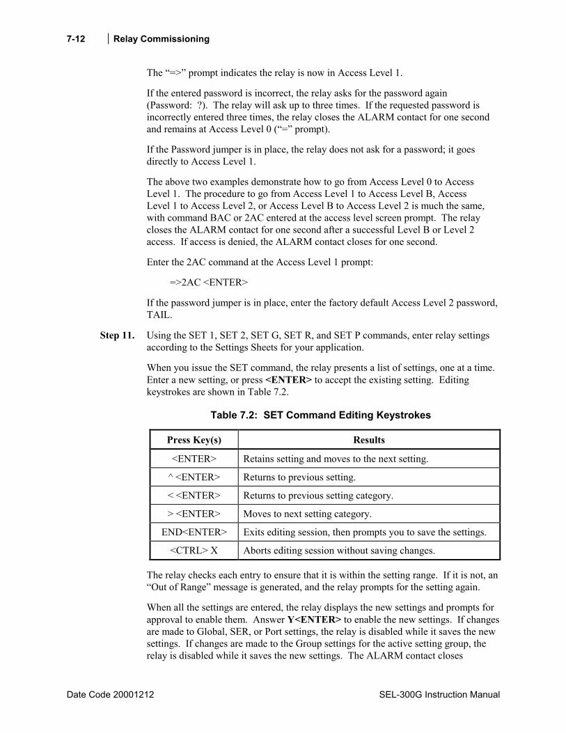
Relay Commissioning
Date Code 20001212 SEL-300G Instruction Manual
7-12
The => prompt indicates the relay is now in Access Level 1.
If the entered password is incorrect, the relay asks for the password again (Password: ?). The relay will ask up to three times. If the requested password is incorrectly entered three times, the relay closes the ALARM contact for one second and remains at Access Level 0 (= prompt).
If the Password jumper is in place, the relay does not ask for a password; it goes directly to Access Level 1.
The above two examples demonstrate how to go from Access Level 0 to Access Level 1. The procedure to go from Access Level 1 to Access Level B, Access Level 1 to Access Level 2, or Access Level B to Access Level 2 is much the same, with command BAC or 2AC entered at the access level screen prompt. The relay closes the ALARM contact for one second after a successful Level B or Level 2 access. If access is denied, the ALARM contact closes for one second.
Enter the 2AC command at the Access Level 1 prompt:
=>2AC <ENTER>
If the password jumper is in place, enter the factory default Access Level 2 password, TAIL.
Step 11. Using the SET 1, SET 2, SET G, SET R, and SET P commands, enter relay settings according to the Settings Sheets for your application.
When you issue the SET command, the relay presents a list of settings, one at a time. Enter a new setting, or press <ENTER> to accept the existing setting. Editing keystrokes are shown in Table 7.2.
Table 7.2: SET Command Editing Keystrokes
Press Key(s) Results
<ENTER> Retains setting and moves to the next setting.
^ <ENTER> Returns to previous setting.
< <ENTER> Returns to previous setting category.
> <ENTER> Moves to next setting category.
END<ENTER> Exits editing session, then prompts you to save the settings.
<CTRL> X Aborts editing session without saving changes.
The relay checks each entry to ensure that it is within the setting range. If it is not, an Out of Range message is generated, and the relay prompts for the setting again.
When all the settings are entered, the relay displays the new settings and prompts for approval to enable them. Answer Y<ENTER> to enable the new settings. If changes are made to Global, SER, or Port settings, the relay is disabled while it saves the new settings. If changes are made to the Group settings for the active setting group, the relay is disabled while it saves the new settings. The ALARM contact closes
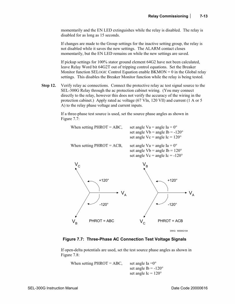
Relay Commissioning 7-13
SEL-300G Instruction Manual Date Code 20000616
momentarily and the EN LED extinguishes while the relay is disabled. The relay is disabled for as long as 15 seconds.
If changes are made to the Group settings for the inactive setting group, the relay is not disabled while it saves the new settings. The ALARM contact closes momentarily, but the EN LED remains on while the new settings are saved.
If pickup settings for 100% stator ground element 64G2 have not been calculated, leave Relay Word bit 64G2T out of tripping control equations. Set the Breaker Monitor function SELOGIC Control Equation enable BKMON = 0 in the Global relay settings. This disables the Breaker Monitor function while the relay is being tested.
Step 12. Verify relay ac connections. Connect the protective relay ac test signal source to the SEL-300G Relay through the ac protection cabinet wiring. (You may connect directly to the relay, however this does not verify the accuracy of the wiring in the protection cabinet.) Apply rated ac voltage (67 Vln, 120 Vll) and current (1 A or 5 A) to the relay phase voltage and current inputs.
If a three-phase test source is used, set the source phase angles as shown in Figure 7.7:
When setting PHROT = ABC, set angle Va = angle Ia = 0° set angle Vb = angle Ib = -120° set angle Vc = angle Ic = 120°
When setting PHROT = ACB, set angle Va = angle Ia = 0° set angle Vb = angle Ib = 120° set angle Vc = angle Ic = -120°
+120°
-120°
VC
VB
VA
PHROT = ABC
+120°
-120°
PHROT = ACB
DWG: M300G104
VB
VC
VA
Figure 7.7: Three-Phase AC Connection Test Voltage Signals
If open-delta potentials are used, set the test source phase angles as shown in Figure 7.8:
When setting PHROT = ABC, set angle Ia =0° set angle Ib = -120° set angle Ic = 120°

Relay Commissioning
Date Code 2000616 SEL-300G Instruction Manual
7-14
set angle Vab = +30° set angle Vcb = +90°
When setting PHROT = ACB, set angle Ia = 0° set angle Ib = 120° set angle Ic = -120° set angle Vab = -30° set angle Vcb = -90°
DWG: M300G200
60° VAB
VCB
PHROT = ABC
60°
VAB
VCB
PHROT = ACB
Figure 7.8: Open-Delta AC Potential Connection Test Voltage Signals
If a single-phase source is used, set the source phase angles to zero and apply the voltage and current to phases A, B, and C in turn.
Use the front-panel or serial port METER function to verify that the relay is measuring voltage and current magnitudes and phase angles correctly, taking into account the relay PTR and CTR settings and the fact that the quantities are displayed in primary units. This step verifies the signal polarity and per-phase ac connections to the relay.
Apply rated ac voltage (67V) to the relay VS and VN inputs if provided and used. Apply rated ac current (1 A or 5 A) to the relay IN input if used. Use the front-panel or serial port METER function to verify that the relay is measuring voltage and current magnitudes and phase angles correctly, taking into account the relay PTRN, PTRS, and CTRN settings and the fact that the quantities are displayed in primary units.
Step 13. Verify optoisolated input connections. Use the front-panel OTHER pushbutton and the TAR function to cause the relay to display Relay Word Row 31 on the relay front-panel LEDs (see Section 9: Front-Panel Operation and Section 10: Serial Port Communications and Commands for more details regarding the front-panel TARGET command). Apply rated dc voltage to the individual relay optoisolated input circuits. As you apply dc voltage to each input, its label will appear in the LCD display and its LED will illuminate.
Execution of the TAR command via the front-panel display remaps the bottom row of the front-panel target LEDs (see Figure 9.3, pushbutton OTHER).
For instance, the TAR 31 command associates the front-panel 87 LED with input IN101. When rated dc voltage is applied to IN101, the 87 LED illuminates. Verify
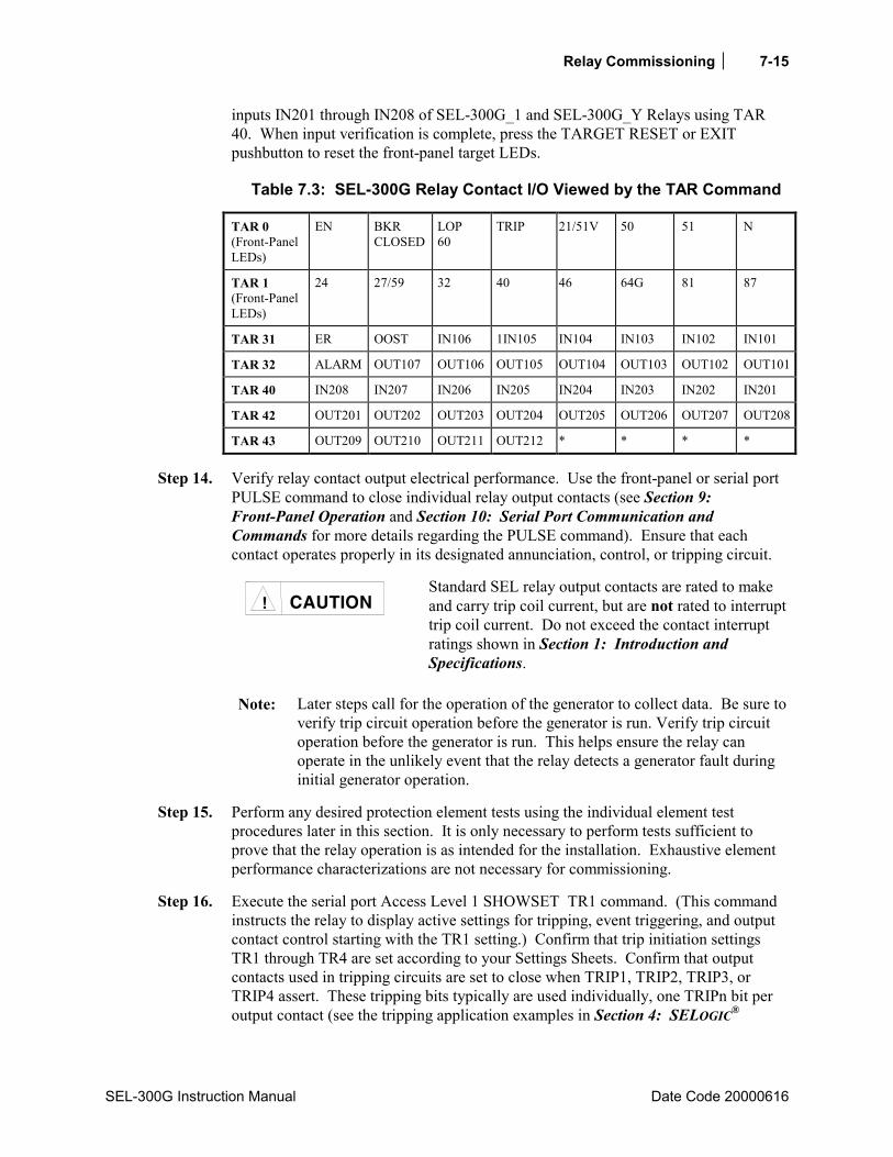
Relay Commissioning 7-15
SEL-300G Instruction Manual Date Code 20000616
inputs IN201 through IN208 of SEL-300G_1 and SEL-300G_Y Relays using TAR 40. When input verification is complete, press the TARGET RESET or EXIT pushbutton to reset the front-panel target LEDs.
Table 7.3: SEL-300G Relay Contact I/O Viewed by the TAR Command
TAR 0 (Front-Panel LEDs)
EN BKR CLOSED
LOP 60
TRIP 21/51V 50 51 N
TAR 1 (Front-Panel LEDs)
24 27/59 32 40 46 64G 81 87
TAR 31 ER OOST IN106 1IN105 IN104 IN103 IN102 IN101
TAR 32 ALARM OUT107 OUT106 OUT105 OUT104 OUT103 OUT102 OUT101
TAR 40 IN208 IN207 IN206 IN205 IN204 IN203 IN202 IN201
TAR 42 OUT201 OUT202 OUT203 OUT204 OUT205 OUT206 OUT207 OUT208
TAR 43 OUT209 OUT210 OUT211 OUT212 * * * *
Step 14. Verify relay contact output electrical performance. Use the front-panel or serial port PULSE command to close individual relay output contacts (see Section 9: Front-Panel Operation and Section 10: Serial Port Communication and Commands for more details regarding the PULSE command). Ensure that each contact operates properly in its designated annunciation, control, or tripping circuit.
CAUTION !
Standard SEL relay output contacts are rated to make and carry trip coil current, but are not rated to interrupt trip coil current. Do not exceed the contact interrupt ratings shown in Section 1: Introduction and Specifications.
Note: Later steps call for the operation of the generator to collect data. Be sure to verify trip circuit operation before the generator is run. Verify trip circuit operation before the generator is run. This helps ensure the relay can operate in the unlikely event that the relay detects a generator fault during initial generator operation.
Step 15. Perform any desired protection element tests using the individual element test procedures later in this section. It is only necessary to perform tests sufficient to prove that the relay operation is as intended for the installation. Exhaustive element performance characterizations are not necessary for commissioning.
Step 16. Execute the serial port Access Level 1 SHOWSET TR1 command. (This command instructs the relay to display active settings for tripping, event triggering, and output contact control starting with the TR1 setting.) Confirm that trip initiation settings TR1 through TR4 are set according to your Settings Sheets. Confirm that output contacts used in tripping circuits are set to close when TRIP1, TRIP2, TRIP3, or TRIP4 assert. These tripping bits typically are used individually, one TRIPn bit per output contact (see the tripping application examples in Section 4: SELOGIC®
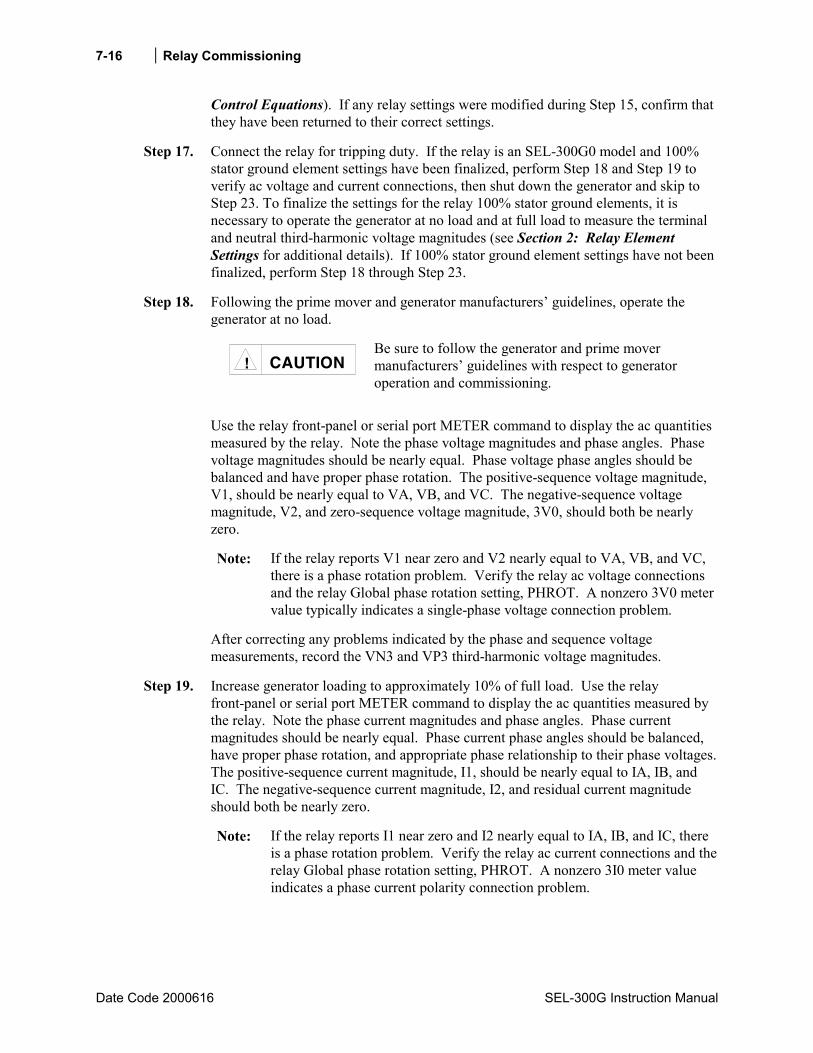
Relay Commissioning
Date Code 2000616 SEL-300G Instruction Manual
7-16
Control Equations). If any relay settings were modified during Step 15, confirm that they have been returned to their correct settings.
Step 17. Connect the relay for tripping duty. If the relay is an SEL-300G0 model and 100% stator ground element settings have been finalized, perform Step 18 and Step 19 to verify ac voltage and current connections, then shut down the generator and skip to Step 23. To finalize the settings for the relay 100% stator ground elements, it is necessary to operate the generator at no load and at full load to measure the terminal and neutral third-harmonic voltage magnitudes (see Section 2: Relay Element Settings for additional details). If 100% stator ground element settings have not been finalized, perform Step 18 through Step 23.
Step 18. Following the prime mover and generator manufacturers guidelines, operate the generator at no load.
CAUTION !
Be sure to follow the generator and prime mover manufacturers guidelines with respect to generator operation and commissioning.
Use the relay front-panel or serial port METER command to display the ac quantities measured by the relay. Note the phase voltage magnitudes and phase angles. Phase voltage magnitudes should be nearly equal. Phase voltage phase angles should be balanced and have proper phase rotation. The positive-sequence voltage magnitude, V1, should be nearly equal to VA, VB, and VC. The negative-sequence voltage magnitude, V2, and zero-sequence voltage magnitude, 3V0, should both be nearly zero.
Note: If the relay reports V1 near zero and V2 nearly equal to VA, VB, and VC, there is a phase rotation problem. Verify the relay ac voltage connections and the relay Global phase rotation setting, PHROT. A nonzero 3V0 meter value typically indicates a single-phase voltage connection problem.
After correcting any problems indicated by the phase and sequence voltage measurements, record the VN3 and VP3 third-harmonic voltage magnitudes.
Step 19. Increase generator loading to approximately 10% of full load. Use the relay front-panel or serial port METER command to display the ac quantities measured by the relay. Note the phase current magnitudes and phase angles. Phase current magnitudes should be nearly equal. Phase current phase angles should be balanced, have proper phase rotation, and appropriate phase relationship to their phase voltages. The positive-sequence current magnitude, I1, should be nearly equal to IA, IB, and IC. The negative-sequence current magnitude, I2, and residual current magnitude should both be nearly zero.
Note: If the relay reports I1 near zero and I2 nearly equal to IA, IB, and IC, there is a phase rotation problem. Verify the relay ac current connections and the relay Global phase rotation setting, PHROT. A nonzero 3I0 meter value indicates a phase current polarity connection problem.

Relay Commissioning 7-17
SEL-300G Instruction Manual Date Code 20000616
If the relay is an SEL-300G1 model, use the front-panel or serial port METER DIFF command to check differential protection quantities. Differential operate current quantities IOP1, IOP2, and IOP3 should be near zero. Note: If the SEL-300G1 Relay METER DIFF function reports nonzero
differential operate currents, there is likely a differential current transformer connection problem or a problem with the TRCON or CTCON settings. Use the Differential Element Commissioning Worksheet later in this section to determine the nature of the connection problem.
Step 20. Operate the generator at full load. Use the front-panel or serial port METER command to display the ac quantities measured by the relay. Note the ac voltage and current magnitude and phase angle measurements, using the same criteria as in Step 19. Having made any necessary corrections during early steps, the measurements should now be correct. Record the terminal and neutral third-harmonic voltage magnitudes VP3 and VN3.
Step 21. Shut down the generator.
Step 22. Calculate settings for the 64G2 element using the measurements taken above and the guidelines shown in Section 2: Relay Element Settings. Using the serial port SET command, enter the newly calculated 64G element settings and add 64G2T to tripping SELOGIC Control Equations. If desired, perform 64G protection element tests to verify the element performance with the new settings.
Step 23. To prepare the relay for operation, it is helpful to clear the relay data buffers. This prevents data generated during installation testing from being confused with operational data collected later. Execute the relay commands in Table 7.4 to clear specific data.
Table 7.4: Serial Port Commands That Clear Relay Data Buffers
Serial Port Command
Task Performed:
MET RD Resets Demand Meter Data
MET RP Resets Peak Demand Meter Data
MET RE Resets Energy Meter Data
MET RM Resets Max/Min Data
HIS C Clears Event Report and History Command Buffers
PRO R Resets Selected Generator Operating Statistic Buffers
SER C Clears Sequential Events Record Buffer
Note: The PRO R and SER C commands should only be used at initial installation. Do not reset the generator operating profiles or SER buffer following routine maintenance unless you are very familiar with the use of the data contained in these buffers.
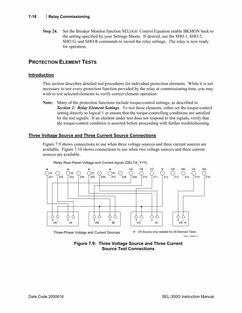
Relay Commissioning
Date Code 2000616 SEL-300G Instruction Manual
7-18
Step 24. Set the Breaker Monitor function SELOGIC Control Equation enable BKMON back to the setting specified by your Settings Sheets. If desired, use the SHO 1, SHO 2, SHO G, and SHO R commands to record the relay settings. The relay is now ready for operation.
PROTECTION ELEMENT TESTS
Introduction
This section describes detailed test procedures for individual protection elements. While it is not necessary to test every protection function provided by the relay at commissioning time, you may wish to test selected elements to verify correct element operation.
Note: Many of the protection functions include torque-control settings, as described in Section 2: Relay Element Settings. To test these elements, either set the torque-control setting directly to logical 1 or ensure that the torque-controlling conditions are satisfied by the test signals. If an element under test does not respond to test signals, verify that the torque-control condition is asserted before proceeding with further troubleshooting.
Three Voltage Source and Three Current Source Connections
Figure 7.9 shows connections to use when three voltage sources and three current sources are available. Figure 7.10 shows connections to use when two voltage sources and three current sources are available.
DWG: M300G113
+ -VA IA
+ -VB IB
+ -VC IC
Three-Phase Voltage and Current Sources
Z01IA
Z02 Z03 Z04 Z05 Z06 Z07 Z08 Z09 Z10 Z11 Z12IB IC IN
VA
Z13 Z14
VB VC N VN NN
Relay Rear-Panel Voltage and Current Inputs (DELTA_Y=Y)
Z15 Z16
VS NS
+ -VS *
* VS Source only needed for 25 Element Tests
Figure 7.9: Three Voltage Source and Three Current
Source Test Connections

Relay Commissioning 7-19
SEL-300G Instruction Manual Date Code 20000616
DWG: M300G220
+ -VAB IA
+ -VCB IB
+ -V IC
Two Voltage and Three Current Sources
Z01IA
Z02 Z03 Z04 Z05 Z06 Z07 Z08 Z09 Z10 Z11 Z12IB IC IN
VA
Z13 Z14
VB VC N VN NN
Relay Rear-Panel Voltage and Current Inputs (DELTA_Y=D)
Z15 Z16
VS NS
+ -VS *
* VS Source only needed for 25 Element Tests
Figure 7.10: Two Voltage Source and Three Current
Source Test Connections
Phase Distance (21) Element
Equipment Needed
• SEL-300G Relay under test. • Two- or Three-Phase AC Voltage and Current Test Source with adjustable magnitude and
phase angle. • PC with terminal emulation software and appropriate serial cable to connect the PC-COM
port to the relay.
Test Source Connections
Connect the voltage and current sources according to Figure 7.9 or Figure 7.10.
Basic Element Operation
The SEL-300G Relay phase distance elements are designed to provide backup protection for phase-to-phase and three-phase faults on the power system external to the generator. The relay provides two independent protection zones. Each zone is equipped with settings that define:
• Forward reach in secondary ohms. • Offset (or reverse reach) in secondary ohms. • Maximum Torque Angle in degrees. • Definite-time delay in seconds. • Delta-wye step-up transformer compensation.

Relay Commissioning
Date Code 2000616 SEL-300G Instruction Manual
7-20
The voltage and current phase shift introduced by a delta-wye step-up transformer changes the voltage and current signals presented to the SEL-300G Relay during a phase-phase fault on the system. The effect is illustrated by Figure 7.11 and Figure 7.12.
VcIc Va
Vb
Ia, Ib
Generator Voltages and CurrentsDuring System B-C Fault
System Voltages and CurrentsDuring System B-C Fault
IBVC VB
IC
VA
VC VA
VB
Generator and System Prefault Voltages
Vc
Va
Vb
G
a
c b
A
CB
B-C Fault
DWG: M300G222
Figure 7.11: Generator Voltage and Current Relationships During a System Phase-to-Phase Fault
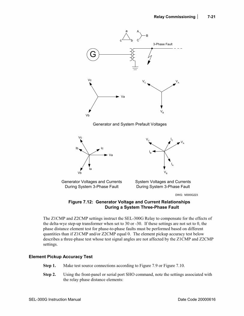
Relay Commissioning 7-21
SEL-300G Instruction Manual Date Code 20000616
G
a
c b
A
CB
3-Phase Fault
Generator and System Prefault Voltages
Vc
Va
Vb
Vc
Ic
Va
Vb
Ib
Generator Voltages and CurrentsDuring System 3-Phase Fault
System Voltages and CurrentsDuring System 3-Phase Fault
IaVB
IA
IC
IB
VA
VC
DWG: M300G223
VC VA
VB
Figure 7.12: Generator Voltage and Current Relationships
During a System Three-Phase Fault
The Z1CMP and Z2CMP settings instruct the SEL-300G Relay to compensate for the effects of the delta-wye step-up transformer when set to 30 or -30. If these settings are not set to 0, the phase distance element test for phase-to-phase faults must be performed based on different quantities than if Z1CMP and/or Z2CMP equal 0. The element pickup accuracy test below describes a three-phase test whose test signal angles are not affected by the Z1CMP and Z2CMP settings.
Element Pickup Accuracy Test
Step 1. Make test source connections according to Figure 7.9 or Figure 7.10.
Step 2. Using the front-panel or serial port SHO command, note the settings associated with the relay phase distance elements:
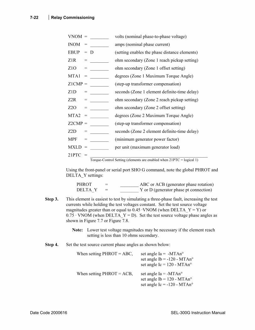
Relay Commissioning
Date Code 2000616 SEL-300G Instruction Manual
7-22
VNOM = ________ volts (nominal phase-to-phase voltage)
INOM = ________ amps (nominal phase current)
EBUP = D (setting enables the phase distance elements)
Z1R = ________ ohm secondary (Zone 1 reach pickup setting)
Z1O = ________ ohm secondary (Zone 1 offset setting)
MTA1 = ________ degrees (Zone 1 Maximum Torque Angle)
Z1CMP = ________ (step-up transformer compensation)
Z1D = ________ seconds (Zone 1 element definite-time delay)
Z2R = ________ ohm secondary (Zone 2 reach pickup setting)
Z2O = ________ ohm secondary (Zone 2 offset setting)
MTA2 = ________ degrees (Zone 2 Maximum Torque Angle)
Z2CMP = ________ (step-up transformer compensation)
Z2D = ________ seconds (Zone 2 element definite-time delay)
MPF = ________ (minimum generator power factor)
MXLD = ________ per unit (maximum generator load)
21PTC = ___________________________________________________ Torque-Control Setting (elements are enabled when 21PTC = logical 1)
Using the front-panel or serial port SHO G command, note the global PHROT and DELTA_Y settings:
PHROT = ________ ABC or ACB (generator phase rotation) DELTA_Y = ________ Y or D (generator phase pt connection)
Step 3. This element is easiest to test by simulating a three-phase fault, increasing the test currents while holding the test voltages constant. Set the test source voltage magnitudes greater than or equal to 0.45 ·VNOM (when DELTA_Y = Y) or 0.75 · VNOM (when DELTA_Y = D). Set the test source voltage phase angles as shown in Figure 7.7 or Figure 7.8.
Note: Lower test voltage magnitudes may be necessary if the element reach setting is less than 10 ohms secondary.
Step 4. Set the test source current phase angles as shown below:
When setting PHROT = ABC, set angle Ia = -MTAn° set angle Ib = -120 - MTAn° set angle Ic = 120 - MTAn°
When setting PHROT = ACB, set angle Ia = -MTAn° set angle Ib = 120 - MTAn° set angle Ic = -120 - MTAn°
Relay Commissioning 7-23
SEL-300G Instruction Manual Date Code 20000616
To predict the test current magnitude where the element will operate, use one of the following equations:
When DELTA_Y = Y:
R1ZVaIop = A secondary
When DELTA_Y = D:
R1Z73.1VabIop ⋅
= A secondary
This calculation assumes that you will increase the magnitude of all three phase currents together, while holding the test voltage constant. When performing the calculation for the Zone 2 pickup, substitute the value of the Z2R setting in place of the Z1R setting.
Note: When transformer compensation is enabled (ZnCMP = +30 or -30), the distance element will pick up at one-third the set reach, or three times the current predicted by the Iop equations above. This is correct operation for the design and settings of the element.
Note: If the calculated test current exceeds your test set capabilities, you need to perform a two-stage test. In the first stage, the test set should apply balanced, three-phase voltage as calculated in Step 3 on the previous page. In the second stage, switch the test set to apply a lower test voltage and a test current that the test set is capable of producing. This approach prevents the loss-of-potential element, 60LOP, from blocking element operation due to low voltage.
When performing this test manually, it is easy to determine when an instantaneous element picks up by viewing the element state directly using the front-panel TARGET function. Press the front-panel OTHER pushbutton, use the Down arrow button to underline the word TAR in the LCD display, then press SELECT. This command sequence causes the LCD display and lower deck of target LEDs to display individual Relay Word rows. Press the Down arrow button twice to display Relay Word Row 39, which contains the distance element indications as shown in Table 7.5.

Relay Commissioning
Date Code 2000616 SEL-300G Instruction Manual
7-24
Table 7.5: Relay Word Row 39 Shows Relay Word Bits for Distance Elements
Target •••• •••• •••• •••• •••• •••• •••• ••••
LED 24 27/59 32 40 46 64G 81 87
TAR 39 Command causes these LEDs to represent:
21PTC
21P1P
21P1T
21P2P
21P2T
*
*
*
With balanced, three-phase voltage applied to the relay and standard settings for the 21PTC torque-control setting, the relay should display the 21PTC Relay Word bit name in the LCD display and illuminate the 24 LED as shown in Table 7.5.
During the manual test, as you change test current magnitudes, you can see the 21P1P and 21P2P Relay Word bits assert and deassert to indicate pickup and dropout of the respective elements.
If you prefer to monitor a contact closure to indicate element pickup, use the Access Level 2 SET command to program an output contact to close when the element under test picks up.
Step 5. Gradually increase the magnitude of all three phase currents. Record the current magnitude applied to the relay when the instantaneous element under test asserts.
21P1P asserted when phase current magnitude equaled: ________ A secondary (Itest).
Use the equation below to calculate the element error (DELTA_Y = Y, Z1CMP = 0):
%100R1Z
R1ZItestVa
error ⋅
−=
error = _________ %
Use the equation below to calculate the element error (DELTA_Y = D, Z1CMP = 0):
%100R1Z
R1ZItest732.1
Vab
error ⋅
−⋅=
error = _________ %
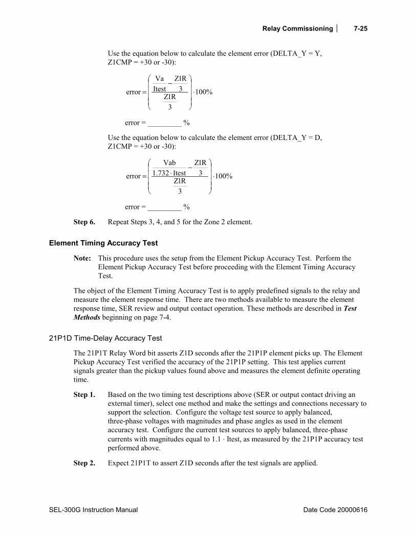
Relay Commissioning 7-25
SEL-300G Instruction Manual Date Code 20000616
Use the equation below to calculate the element error (DELTA_Y = Y, Z1CMP = +30 or -30):
%100
3R1Z
3R1Z
ItestVa
error ⋅
−=
error = _________ %
Use the equation below to calculate the element error (DELTA_Y = D, Z1CMP = +30 or -30):
%100
3R1Z
3R1Z
Itest732.1Vab
error ⋅
−⋅=
error = _________ %
Step 6. Repeat Steps 3, 4, and 5 for the Zone 2 element.
Element Timing Accuracy Test
Note: This procedure uses the setup from the Element Pickup Accuracy Test. Perform the Element Pickup Accuracy Test before proceeding with the Element Timing Accuracy Test.
The object of the Element Timing Accuracy Test is to apply predefined signals to the relay and measure the element response time. There are two methods available to measure the element response time, SER review and output contact operation. These methods are described in Test Methods beginning on page 7-4.
21P1D Time-Delay Accuracy Test
The 21P1T Relay Word bit asserts Z1D seconds after the 21P1P element picks up. The Element Pickup Accuracy Test verified the accuracy of the 21P1P setting. This test applies current signals greater than the pickup values found above and measures the element definite operating time.
Step 1. Based on the two timing test descriptions above (SER or output contact driving an external timer), select one method and make the settings and connections necessary to support the selection. Configure the voltage test source to apply balanced, three-phase voltages with magnitudes and phase angles as used in the element accuracy test. Configure the current test sources to apply balanced, three-phase currents with magnitudes equal to 1.1 ⋅ Itest, as measured by the 21P1P accuracy test performed above.
Step 2. Expect 21P1T to assert Z1D seconds after the test signals are applied.
Relay Commissioning
Date Code 2000616 SEL-300G Instruction Manual
7-26
Step 3. Apply the test voltages calculated in Step 1. Next, apply the test currents and record the element operating time, Ttest. Remove the test voltages and currents.
Ttest = _________ seconds
Step 4. Calculate the relay timing error using the equation:
%100D1Z
D1ZTtesterror ⋅
−=
error = _________ %
Repeat the test for Zone 2, if desired.
Volts/Hertz (24) Element
Equipment Needed
• SEL-300G Relay under test. • Two- or Three-Phase AC Voltage Test Source with adjustable magnitude and phase angle. • PC with terminal emulation software and appropriate serial cable to connect the PC-COM
port to the relay.
Test Source Connections
When DELTA_Y = Y, connect the voltage sources according to Figure 7.9. When DELTA_Y = D, connect the voltage sources according to Figure 7.10. Current sources are not needed for this test.
Basic Element Operation
The SEL-300G Relay volts/hertz element is designed to detect generator overexcitation that occurs when the generator terminal voltage is increased or operating frequency is decreased. The relay measures the generator phase-to-phase voltages and the generator frequency, then calculates the volts/hertz using the equation:
%100VNOMFNOM
FreqVppHz/V ⋅⋅=
Where: Vpp = measured generator phase-to-phase voltage Freq = measured generator frequency FNOM = nominal generator frequency (Relay Global Setting) VNOM = nominal generator phase-to-phase voltage
When the measured phase-to-phase voltage and generator frequency are equal to the nominal settings FNOM and VNOM, the result of the equation above is 100%. If the phase-to-phase voltage increases or the operating frequency decreases, the equation result exceeds 100% and, depending on settings, the relay overexcitation elements can pick up.

Relay Commissioning 7-27
SEL-300G Instruction Manual Date Code 20000616
The 24D1 element is a definite-time volts/hertz element that typically is applied as an overexcitation alarm. If measured volts/hertz exceed the 24D1P setting, the relay asserts the 24D1 Relay Word bit to logical 1. If this condition continues for 24D1D seconds, the relay asserts the 24D1T Relay Word bit to logical 1. After the excessive volts/hertz condition vanishes, the relay deasserts both Relay Word bits to logical 0.
The 24C2 element is a composite time-delayed element. You can enable this element with a dual-level definite-time characteristic (24CCS = DD), a simple inverse-time characteristic (24CCS = I), or a composite characteristic with inverse-time and definite-time operating areas (see Section 2: Relay Element Settings for a complete description of the element).
Element Pickup Accuracy Test
Step 1. Make test source connections according to Figure 7.9 or Figure 7.10. Current sources are not required for this test and may be left disconnected.
Step 2. Using the front-panel or serial port SHO command, note the settings associated with the relay volts/hertz element:
VNOM = ________ volts (nominal phase-to-phase voltage) E24 = Y (setting enables the volts/hertz elements) 24D1P = ________ % volts/hertz (alarm element pickup setting) 24D1D = ________ seconds (alarm element definite-time delay) 24CCS = ________ (OFF, I, DD, ID; overexcitation element operating time
curve shape) 24IP = ________ % volts/hertz (inverse-time element pickup; shown if
24CCS = I or ID) 24IC = ________ (inverse-time element curve shape; shown if 24CCS = I
or ID) 24ITD = ________ (inverse-time element time-dial; shown if 24CCS = I or ID) 24D2P1 = ________ % volts/hertz (definite-time pickup 1; shown if
24CCS = DD) 24D2D1 = ________ seconds (definite-time delay 1; shown if 24CCS = DD) 24D2P2 = ________ % volts/hertz (definite-time pickup 2; shown if
24CCS = DD or ID) 24D2D2 = ________ seconds (definite-time delay 2; shown if 24CCS = DD or
ID) 24CR = ________ seconds (24C2 element linear reset time) 24TC = __________________________________________________________
Torque-Control Setting (elements are enabled when 24TC = logical 1)
Using the front-panel or serial port SHO G command, note the global FNOM, PHROT, and DELTA_Y settings:
FNOM = ________ Hz (nominal generator frequency) PHROT = ________ ABC or ACB (generator phase rotation) DELTA_Y = ________ Y or D (phase potential connection)
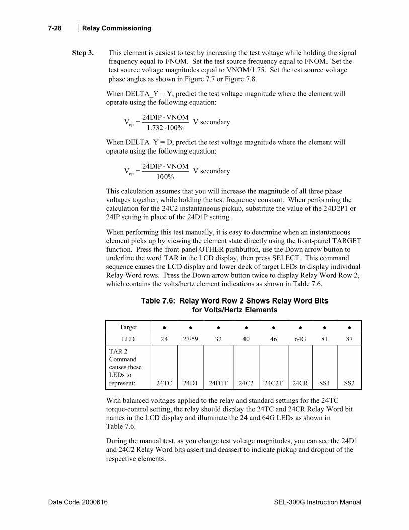
Relay Commissioning
Date Code 2000616 SEL-300G Instruction Manual
7-28
Step 3. This element is easiest to test by increasing the test voltage while holding the signal frequency equal to FNOM. Set the test source frequency equal to FNOM. Set the test source voltage magnitudes equal to VNOM/1.75. Set the test source voltage phase angles as shown in Figure 7.7 or Figure 7.8.
When DELTA_Y = Y, predict the test voltage magnitude where the element will operate using the following equation:
%100732.1VNOMP1D24Vop ⋅
⋅= V secondary
When DELTA_Y = D, predict the test voltage magnitude where the element will operate using the following equation:
%100VNOMP1D24Vop
⋅= V secondary
This calculation assumes that you will increase the magnitude of all three phase voltages together, while holding the test frequency constant. When performing the calculation for the 24C2 instantaneous pickup, substitute the value of the 24D2P1 or 24IP setting in place of the 24D1P setting.
When performing this test manually, it is easy to determine when an instantaneous element picks up by viewing the element state directly using the front-panel TARGET function. Press the front-panel OTHER pushbutton, use the Down arrow button to underline the word TAR in the LCD display, then press SELECT. This command sequence causes the LCD display and lower deck of target LEDs to display individual Relay Word rows. Press the Down arrow button twice to display Relay Word Row 2, which contains the volts/hertz element indications as shown in Table 7.6.
Table 7.6: Relay Word Row 2 Shows Relay Word Bits for Volts/Hertz Elements
Target •••• •••• •••• •••• •••• •••• •••• ••••
LED 24 27/59 32 40 46 64G 81 87
TAR 2 Command causes these LEDs to represent:
24TC
24D1
24D1T
24C2
24C2T
24CR
SS1
SS2
With balanced voltages applied to the relay and standard settings for the 24TC torque-control setting, the relay should display the 24TC and 24CR Relay Word bit names in the LCD display and illuminate the 24 and 64G LEDs as shown in Table 7.6.
During the manual test, as you change test voltage magnitudes, you can see the 24D1 and 24C2 Relay Word bits assert and deassert to indicate pickup and dropout of the respective elements.
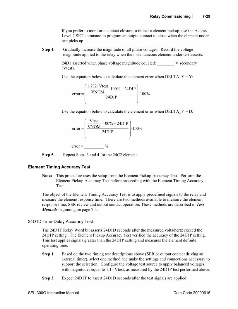
Relay Commissioning 7-29
SEL-300G Instruction Manual Date Code 20000616
If you prefer to monitor a contact closure to indicate element pickup, use the Access Level 2 SET command to program an output contact to close when the element under test picks up.
Step 4. Gradually increase the magnitude of all phase voltages. Record the voltage magnitude applied to the relay when the instantaneous element under test asserts.
24D1 asserted when phase voltage magnitude equaled: ________ V secondary (Vtest).
Use the equation below to calculate the element error when DELTA_Y = Y:
%100P1D24
P1D24%100VNOM
Vtest732.1
error ⋅
−⋅⋅
=
Use the equation below to calculate the element error when DELTA_Y = D:
%100P1D24
P1D24%100VNOMVtest
error ⋅
−⋅=
error = _________ %
Step 5. Repeat Steps 3 and 4 for the 24C2 element.
Element Timing Accuracy Test
Note: This procedure uses the setup from the Element Pickup Accuracy Test. Perform the Element Pickup Accuracy Test before proceeding with the Element Timing Accuracy Test.
The object of the Element Timing Accuracy Test is to apply predefined signals to the relay and measure the element response time. There are two methods available to measure the element response time, SER review and output contact operation. These methods are described in Test Methods beginning on page 7-4.
24D1D Time-Delay Accuracy Test
The 24D1T Relay Word bit asserts 24D1D seconds after the measured volts/hertz exceed the 24D1P setting. The Element Pickup Accuracy Test verified the accuracy of the 24D1P setting. This test applies signals greater than the 24D1P setting and measures the element definite operating time.
Step 1. Based on the two timing test descriptions above (SER or output contact driving an external timer), select one method and make the settings and connections necessary to support the selection. Configure the voltage test source to apply balanced voltages with magnitudes equal to 1.1 ⋅ Vtest, as measured by the 24D1P test performed above.
Step 2. Expect 24D1T to assert 24D1D seconds after the test signals are applied.

Relay Commissioning
Date Code 2000616 SEL-300G Instruction Manual
7-30
Step 3. Apply the test voltages calculated in Step 1 and record the element operating time, Ttest. Remove the test voltages.
Ttest = _________ seconds
Step 4. Calculate the relay timing error using the equation:
%100D1D24
D1D24Ttesterror ⋅
−=
error = _________ %
24C2 Time-Delay Accuracy Test, 24CCS = DD
When 24CCS = DD, the 24C2 element operates as a definite-time delayed element with two independent time delays, each associated with an independent pickup setting, as shown in Figure 7.13. This test procedure uses up to four test points to verify that the definite-time delays are operating properly.
t(seconds)
24D2D1setting
24D2D2setting
24D
2P1
setti
ng
Test
1
Test
3 (o
pt)
24D
2P2
setti
ng
Test
2
Test
4 (o
pt)
V/Hz
DWG: M300G105
Figure 7.13: 24C2 Time-Delay Test Points, 24CCS = DD
Step 1. When DELTA_Y = Y, use the equations below to calculate the test voltage magnitudes for Test Point 1, Test Point 2, and the optional Test Points 3 and 4, if desired, using the equations below.
%100732.1VNOM1P2D241.11Vtest
⋅⋅⋅= V secondary
Vtest1 = ___________ V secondary

Relay Commissioning 7-31
SEL-300G Instruction Manual Date Code 20000616
Select optional Test Point 3 such that
1.1 ⋅ 24D2P1 < Test Point 3 < 24D2P2 volts/hertz
Test Point 3 = ____________ volts/hertz
%100732.1VNOM3intTestPo3Vtest
⋅⋅= V secondary
Vtest3 = ___________ V secondary
%100732.1VNOM2P2D241.12Vtest
⋅⋅⋅= V secondary
Vtest2 = ___________ V secondary
Select optional Test Point 4 such that
1.1 ⋅ 24D2P2 < Test Point 4 volts/hertz
Test Point 4 = ____________ volts/hertz
%100732.1VNOM4intTestPo4Vtest
⋅⋅= V secondary
Vtest4 = ___________ V secondary
When DELTA_Y = D, use the equations below to calculate the test voltage magnitudes for Test Point 1, Test Point 2, and the optional Test Points 3 and 4, if desired, using the equations below.
%100VNOM1P2D241.11Vtest ⋅⋅= V secondary
Vtest1 = ___________ V secondary
Select optional Test Point 3 such that
1.1 ⋅ 24D2P1 < Test Point 3 < 24D2P2 volts/hertz
Test Point 3 = ____________ volts/hertz
%100VNOM3intTestPo3Vtest ⋅= V secondary
Vtest3 = ___________ V secondary
%100VNOM2P2D241.12Vtest ⋅⋅= V secondary
Vtest2 = ___________ V secondary
Select optional Test Point 4 such that
1.1 ⋅ 24D2P2 < Test Point 4 volts/hertz
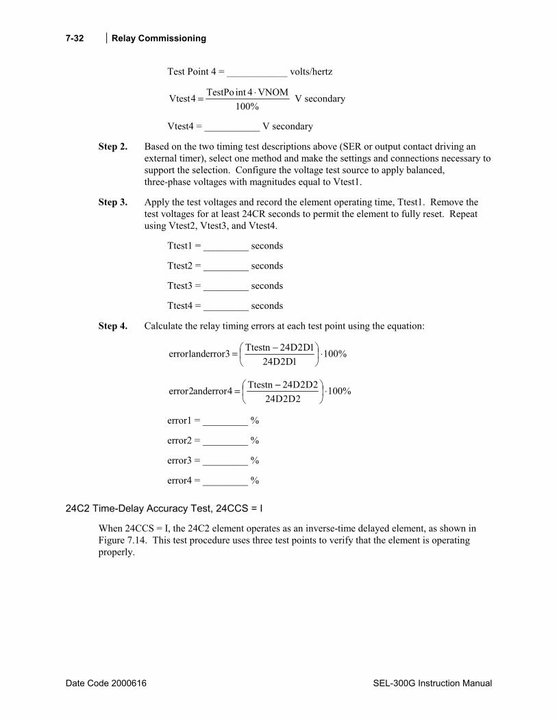
Relay Commissioning
Date Code 2000616 SEL-300G Instruction Manual
7-32
Test Point 4 = ____________ volts/hertz
%100VNOM4intTestPo4Vtest ⋅= V secondary
Vtest4 = ___________ V secondary
Step 2. Based on the two timing test descriptions above (SER or output contact driving an external timer), select one method and make the settings and connections necessary to support the selection. Configure the voltage test source to apply balanced, three-phase voltages with magnitudes equal to Vtest1.
Step 3. Apply the test voltages and record the element operating time, Ttest1. Remove the test voltages for at least 24CR seconds to permit the element to fully reset. Repeat using Vtest2, Vtest3, and Vtest4.
Ttest1 = _________ seconds
Ttest2 = _________ seconds
Ttest3 = _________ seconds
Ttest4 = _________ seconds
Step 4. Calculate the relay timing errors at each test point using the equation:
%1001D2D24
1D2D24Ttestn3errorand1error ⋅
−=
%1002D2D24
2D2D24Ttestn4errorand2error ⋅
−=
error1 = _________ %
error2 = _________ %
error3 = _________ %
error4 = _________ %
24C2 Time-Delay Accuracy Test, 24CCS = I
When 24CCS = I, the 24C2 element operates as an inverse-time delayed element, as shown in Figure 7.14. This test procedure uses three test points to verify that the element is operating properly.
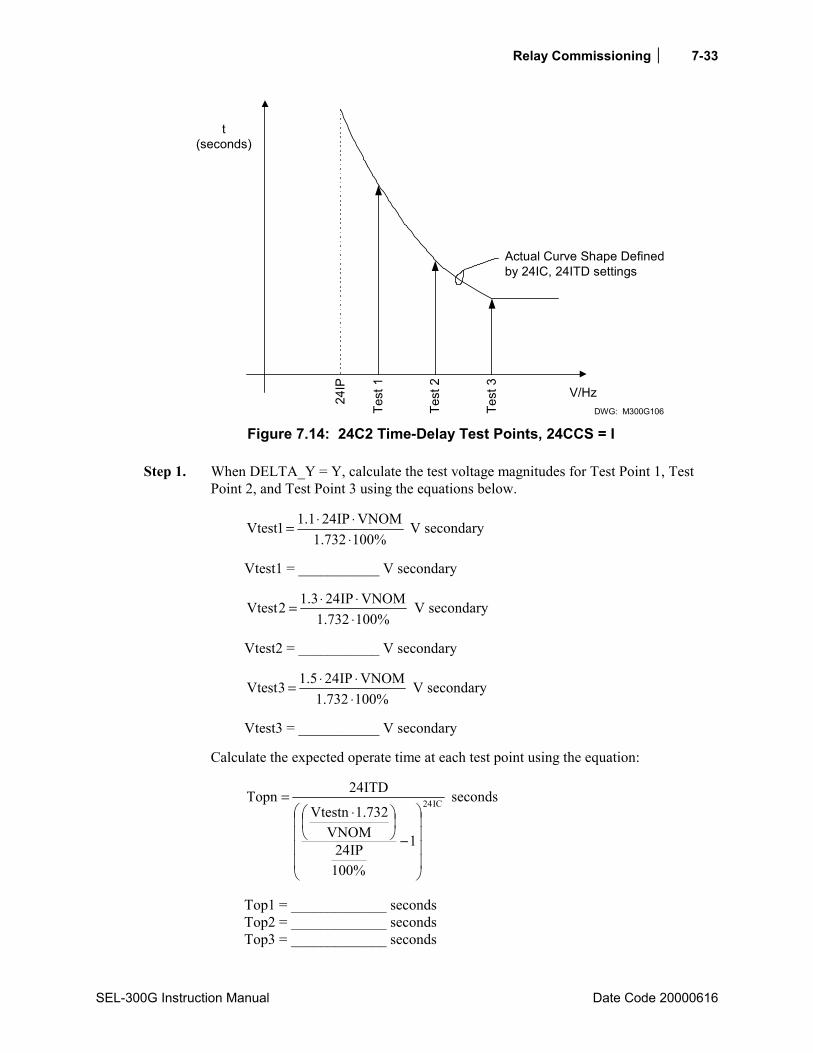
Relay Commissioning 7-33
SEL-300G Instruction Manual Date Code 20000616
t(seconds)
24IP
Test
1
Test
2
Test
3 V/HzDWG: M300G106
Actual Curve Shape Definedby 24IC, 24ITD settings
Figure 7.14: 24C2 Time-Delay Test Points, 24CCS = I
Step 1. When DELTA_Y = Y, calculate the test voltage magnitudes for Test Point 1, Test Point 2, and Test Point 3 using the equations below.
%100732.1VNOMIP241.11Vtest
⋅⋅⋅= V secondary
Vtest1 = ___________ V secondary
%100732.1VNOMIP243.12Vtest
⋅⋅⋅= V secondary
Vtest2 = ___________ V secondary
%100732.1VNOMIP245.13Vtest
⋅⋅⋅= V secondary
Vtest3 = ___________ V secondary
Calculate the expected operate time at each test point using the equation:
IC24
1
%100IP24
VNOM732.1Vtestn
ITD24Topn
−
⋅= seconds
Top1 = _____________ seconds Top2 = _____________ seconds Top3 = _____________ seconds

Relay Commissioning
Date Code 2000616 SEL-300G Instruction Manual
7-34
Note: The Topn equation above assumes that the test voltage frequency is equal to FNOM.
When DELTA_Y = D, calculate the test voltage magnitudes for Test Point 1, Test Point 2, and Test Point 3 using the equations below.
%100VNOMIP241.11Vtest ⋅⋅= V secondary
Vtest1 = ___________ V secondary
%100VNOMIP243.12Vtest ⋅⋅= V secondary
Vtest2 = ___________ V secondary
%100VNOMIP245.13Vtest ⋅⋅= V secondary
Vtest3 = ___________ V secondary
Calculate the expected operate time at each test point using the equation:
IC24
1
%100IP24
VNOMVtestn
ITD24Topn
−
= seconds
Top1 = _____________ seconds Top2 = _____________ seconds Top3 = _____________ seconds
Note: The Topn equation above assumes that the test voltage frequency is equal to FNOM.
Step 2. Based on the two timing test descriptions above (SER or output contact driving an external timer), select one method and make the settings and connections necessary to support the selection. Configure the voltage test source to apply balanced, three-phase voltages with magnitudes equal to Vtest1.
Step 3. Apply the test voltages and record the element operating time, Ttest1. Remove the test voltages for at least 24CR seconds to permit the element to fully reset. Repeat using Vtest2 and Vtest3.
Ttest1 = _________ seconds Ttest2 = _________ seconds Ttest3 = _________ seconds
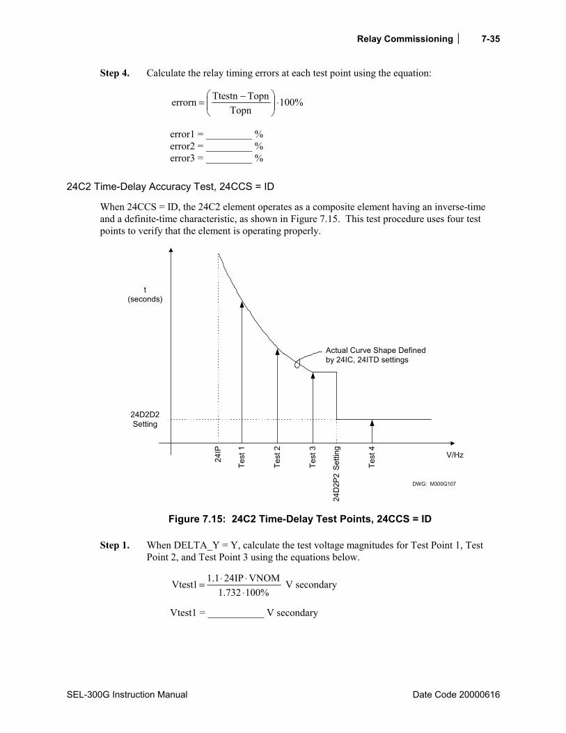
Relay Commissioning 7-35
SEL-300G Instruction Manual Date Code 20000616
Step 4. Calculate the relay timing errors at each test point using the equation:
%100Topn
TopnTtestnerrorn ⋅
−=
error1 = _________ % error2 = _________ % error3 = _________ %
24C2 Time-Delay Accuracy Test, 24CCS = ID
When 24CCS = ID, the 24C2 element operates as a composite element having an inverse-time and a definite-time characteristic, as shown in Figure 7.15. This test procedure uses four test points to verify that the element is operating properly.
t(seconds)
24IP
Test
1
Test
2
Test
3 V/Hz
DWG: M300G107
Actual Curve Shape Definedby 24IC, 24ITD settings
24D
2P2
Setti
ng
Test
4
24D2D2Setting
Figure 7.15: 24C2 Time-Delay Test Points, 24CCS = ID
Step 1. When DELTA_Y = Y, calculate the test voltage magnitudes for Test Point 1, Test Point 2, and Test Point 3 using the equations below.
%100732.1VNOMIP241.11Vtest
⋅⋅⋅= V secondary
Vtest1 = ___________ V secondary

Relay Commissioning
Date Code 2000616 SEL-300G Instruction Manual
7-36
%100732.1VNOMIP243.12Vtest
⋅⋅⋅= V secondary
Vtest2 = ___________ V secondary
%100732.1VNOMIP245.13Vtest
⋅⋅⋅= V secondary
Vtest3 = ___________ V secondary
Note: For Test Points 1, 2, and 3, the example uses 1.1, 1.3, and 1.5 multipliers of 24IP. However, these test points should be selected such that they remain in the inverse-timing area of the curve. If either 1.3⋅24IP or 1.5⋅24IP is greater than 24D2P2, select lower values for the multipliers.
Select Test Point 4 such that
1.1 ⋅ 24D2P2 < Test Point 4 % volts/hertz
Test Point 4 = ____________% volts/hertz
%100732.1VNOM4intTestPo4Vtest
⋅⋅= V secondary
Vtest4 = ___________ V secondary
Calculate the expected operate time at Test Points 1, 2, and 3 using the equation:
IC24
1
%100IP24
VNOM732.1Vtestn
ITD24Topn
−
⋅= seconds
Top1 = _____________ seconds Top2 = _____________ seconds Top3 = _____________ seconds Top4 = 24D2D2 seconds = _________ seconds
Note: The Topn equation above assumes that the test voltage is applied at a frequency equal to FNOM.
When DELTA_Y = D, calculate the test voltage magnitudes for Test Point 1, Test Point 2, and Test Point 3 using the equations below.
%100VNOMIP241.11Vtest ⋅⋅= V secondary
Vtest1 = ___________ V secondary
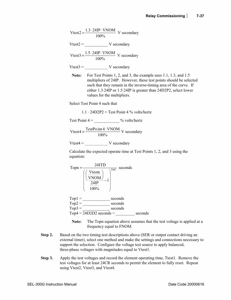
Relay Commissioning 7-37
SEL-300G Instruction Manual Date Code 20000616
%100VNOMIP243.12Vtest ⋅⋅= V secondary
Vtest2 = ___________ V secondary
%100VNOMIP245.13Vtest ⋅⋅= V secondary
Vtest3 = ___________ V secondary
Note: For Test Points 1, 2, and 3, the example uses 1.1, 1.3, and 1.5 multipliers of 24IP. However, these test points should be selected such that they remain in the inverse-timing area of the curve. If either 1.3⋅24IP or 1.5⋅24IP is greater than 24D2P2, select lower values for the multipliers.
Select Test Point 4 such that
1.1 ⋅ 24D2P2 < Test Point 4 % volts/hertz
Test Point 4 = ____________ % volts/hertz
%100VNOM4intTestPo4Vtest ⋅= V secondary
Vtest4 = ___________ V secondary
Calculate the expected operate time at Test Points 1, 2, and 3 using the equation:
IC24
1
%100IP24
VNOMVtestn
ITD24Topn
−
= seconds
Top1 = _____________ seconds Top2 = _____________ seconds Top3 = _____________ seconds Top4 = 24D2D2 seconds = _________ seconds
Note: The Topn equation above assumes that the test voltage is applied at a frequency equal to FNOM.
Step 2. Based on the two timing test descriptions above (SER or output contact driving an external timer), select one method and make the settings and connections necessary to support the selection. Configure the voltage test source to apply balanced, three-phase voltages with magnitudes equal to Vtest1.
Step 3. Apply the test voltages and record the element operating time, Ttest1. Remove the test voltages for at least 24CR seconds to permit the element to fully reset. Repeat using Vtest2, Vtest3, and Vtest4.
Relay Commissioning
Date Code 2000616 SEL-300G Instruction Manual
7-38
Ttest1 = _________ seconds Ttest2 = _________ seconds Ttest3 = _________ seconds Ttest4 = _________ seconds
Step 4. Calculate the relay timing errors at each test point using the equation:
%100Topn
TopnTtestnerrorn ⋅
−=
error1 = _________ % error2 = _________ % error3 = _________ % error4 = _________ %
Synchronism Checking (25) Function
Equipment Needed
• SEL-300G Relay under test. • Three- or Four-Phase AC Voltage Test Source with adjustable magnitude, phase angle, and
frequency. • PC with terminal emulation software and appropriate serial cable to connect the PC-COM
port to the relay.
Test Source Connections
Connect the voltage sources according to Figure 7.9 or Figure 7.10.
Basic Element Operation
The SEL-300G Relay synchronism checking function is designed to ensure that the generator and system voltage magnitudes, phase angles, and frequencies are matched within settable limits before the generator breaker can be closed. Individually, the limit checks are simple to test.
First, the relay compares the magnitude of the VS input voltage to the 25VHI and 25VLO settings to ensure that the system voltage magnitude is within an acceptable window.
Next, the relay calculates the magnitude and phase angle of the generator voltage designated by the SYNCP setting. The magnitude is multiplied by the 25RCF setting and the phase angle is adjusted by the COMPA setting. We refer to the result as VP.
The relay compares the magnitude of VP to the 25VHI and 25VLO settings, to ensure the generator voltage is within the acceptable window. If the 25VDIF setting is not OFF, the relay compares the magnitudes of VP and VS to ensure they are within 25VDIF percent of each other.
Next, the relay calculates slip frequency using the frequency of the VS signal and the frequency measured on the VA or VAB input. By definition, the VA/VAB frequency is the same as the VP frequency, as all three generator phases turn together. The relay compares the slip frequency to the 25SHI and 25SLO settings to ensure the slip is within the window defined by those settings.

Relay Commissioning 7-39
SEL-300G Instruction Manual Date Code 20000616
Finally, the relay calculates two phase angle differences between VS and VP. The first difference is the absolute (uncompensated) difference. The second difference is compensated by SLIP⋅TCLOSD⋅360°. The compensated phase angle difference is a predictive value. It predicts the phase angle difference that will be present between VP and VS in TCLOSD seconds, assuming that the SLIP is constant between now and then. The relay uses the uncompensated phase angle difference to create the 25A2 and CFA elements. It uses the compensated differences to create the 25A1 and 25C elements.
Voltage Element Accuracy Test
Step 1. Make test source connections according to Figure 7.9 or Figure 7.10.
Step 2. Using the front-panel or serial port SHO command, note the settings associated with the relay synch-check function:
E25 = Y (setting enables the synch check function)
25VLO = ________ volts secondary (minimum acceptable system voltage)
25VHI = ________ volts secondary (maximum acceptable system voltage)
25VDIF = ________ percent (maximum voltage difference)
25RCF = ________ (voltage ratio correction factor)
25SLO = ________ Hz (minimum acceptable slip frequency)
25SHI = ________ Hz (maximum acceptable slip frequency)
COMPA = ________ degrees (transformer compensation angle)
25ANG1 = ________ degrees (maximum angle 1)
25ANG2 = ________ degrees (maximum angle 2)
CANGLE = _______ degrees (target breaker close angle)
TCLOSD = ________ seconds (breaker closing time)
CFANGL = ________ degrees (breaker close failure angle)
27VSP = ________ volts secondary (dead-bus undervoltage pickup)
BSYNCH = __________________________________________________ Block Synch Check (function is blocked when BSYNCH = logical 1)
Using the front-panel or serial port SHO G command, note the global FNOM, PHROT and DELTA_Y settings:
FNOM = ________ Hz (nominal system frequency) PHROT = ________ ABC or ACB (generator phase rotation) DELTA_Y = ________ Y or D (generator phase pt connection)
Step 3. The voltage elements are easiest to test by applying all three phase voltages and VS, then adjusting the applied voltage magnitudes to cause the elements under test to pick up and drop out. A combination of relay settings determine the voltage phase angles

Relay Commissioning
Date Code 2000616 SEL-300G Instruction Manual
7-40
you should apply to test the synch-check elements. Refer to Table 7.7 and make the test source settings suggested for your combination of SYNCP, COMPA, DELTA_Y, and PHROT settings.
Table 7.7: Synch-Check Element Test Voltage Phase Angles
VS
Generator Voltages When Angle = 0°°°°
Relay Settings
VP and Error Calculation
0o
VS
VA
0o
-120oVB (VC)
120oVC (VB)
SYNCP = VA
COMPA = 0
DELTA_Y = Y
PHROT = B(C)
RCF25VAVP ⋅=
( ) %100VLO25
VLO25RCF25VTestPerrorP ⋅
−⋅=
0o
VS
VB
0o
-120oVC (VA)
120oVA (VC)
SYNCP = VB
COMPA = 0
DELTA_Y = Y
PHROT = B(C)
RCF25VBVP ⋅=
( ) %100VLO25
VLO25RCF25VTestPerrorP ⋅
−⋅=
0o
VS
VC
0o
-120oVA (VB)
120oVB (VA)
SYNCP = VC
COMPA = 0
DELTA_Y = Y
PHROT = B(C)
RCF25VCVP ⋅=
( ) %100VLO25
VLO25RCF25VTestPerrorP ⋅
−⋅=
0o
VS
VC90o
VB
-150o
-30o
VA SYNCP = VAB
COMPA = 0
DELTA_Y = Y
PHROT = B
RCF25732.1VAVP ⋅⋅=
( ) %100VLO25
VLO25RCF25732.1VTestPerrorP ⋅
−⋅⋅=
0o
VS
VA90o
VC
-150o
-30o
VB SYNCP = VBC
COMPA = 0
DELTA_Y = Y
PHROT = B
RCF25732.1VBVP ⋅⋅=
( ) %100VLO25
VLO25RCF25732.1VTestPerrorP ⋅
−⋅⋅=

Relay Commissioning 7-41
SEL-300G Instruction Manual Date Code 20000616
VS
Generator Voltages When Angle = 0°°°°
Relay Settings
VP and Error Calculation
0o
VS
VA
-90o
VC
150o
30o
VB
SYNCP = VAB
COMPA = 0
DELTA_Y = Y
PHROT = C
RCF25732.1VAVP ⋅⋅=
( ) %100VLO25
VLO25RCF25732.1VTestPerrorP ⋅
−⋅⋅=
0o
VS
VB
-90o
VA
150o
30o
VC
SYNCP = VBC
COMPA = 0
DELTA_Y = Y
PHROT = C
RCF25732.1VBVP ⋅⋅=
( ) %100VLO25
VLO25RCF25732.1VTestPerrorP ⋅
−⋅⋅=
0o
VS
VCB 90o
30o
VAB
SYNCP = VA
COMPA = 0
DELTA_Y = D
PHROT = B
RCF25732.1
VABVP ⋅=
%100VLO25
VLO25RCF25732.1
VTestP
errorP ⋅
−
⋅=
0o
VS
VCB
150o -150o
VAB
SYNCP = VB
COMPA = 0
DELTA_Y = D
PHROT = B
RCF25732.1
VABVP ⋅=
%100VLO25
VLO25RCF25732.1
VTestP
errorP ⋅
−
⋅=
0o
VS
VAB
-30o
-90o
VCB
SYNCP = VC
COMPA = 0
DELTA_Y = D
PHROT = B
RCF25732.1
VABVP ⋅=
%100VLO25
VLO25RCF25732.1
VTestP
errorP ⋅
−
⋅=
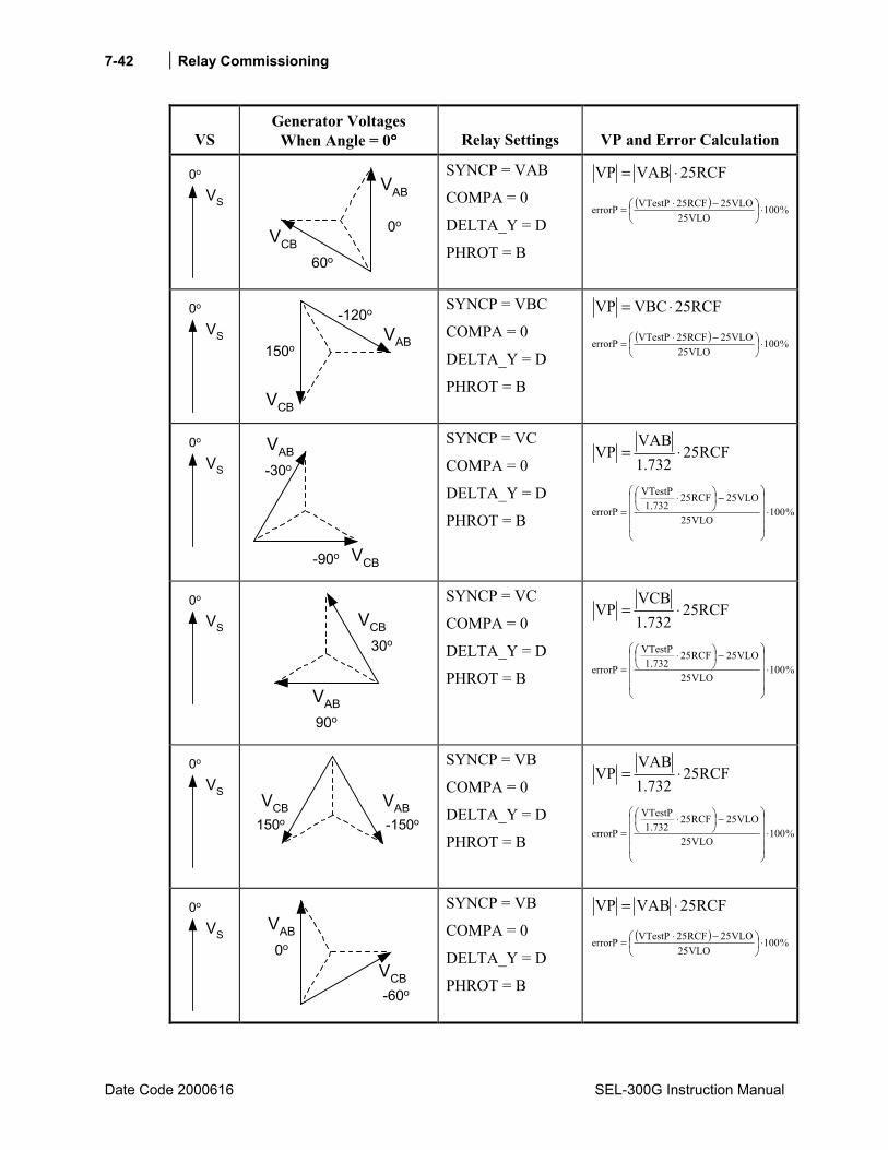
Relay Commissioning
Date Code 2000616 SEL-300G Instruction Manual
7-42
VS
Generator Voltages When Angle = 0°°°°
Relay Settings
VP and Error Calculation
0o
VS
VAB
60o
0oVCB
SYNCP = VAB
COMPA = 0
DELTA_Y = D
PHROT = B
RCF25VABVP ⋅=
( ) %100VLO25
VLO25RCF25VTestPerrorP ⋅
−⋅=
0o
VS
VAB150o
-120o
VCB
SYNCP = VBC
COMPA = 0
DELTA_Y = D
PHROT = B
RCF25VBCVP ⋅=
( ) %100VLO25
VLO25RCF25VTestPerrorP ⋅
−⋅=
0o
VS
VAB-30o
-90o VCB
SYNCP = VC
COMPA = 0
DELTA_Y = D
PHROT = B
RCF25732.1
VABVP ⋅=
%100VLO25
VLO25RCF25732.1
VTestP
errorP ⋅
−
⋅=
0o
VS
VAB90o
30o
VCB
SYNCP = VC
COMPA = 0
DELTA_Y = D
PHROT = B
RCF25732.1
VCBVP ⋅=
%100VLO25
VLO25RCF25732.1
VTestP
errorP ⋅
−
⋅=
0o
VS
VAB150o -150o
VCB
SYNCP = VB
COMPA = 0
DELTA_Y = D
PHROT = B
RCF25732.1
VABVP ⋅=
%100VLO25
VLO25RCF25732.1
VTestP
errorP ⋅
−
⋅=
0o
VS
VAB0o
-60o
VCB
SYNCP = VB
COMPA = 0
DELTA_Y = D
PHROT = B
RCF25VABVP ⋅=
( ) %100VLO25
VLO25RCF25VTestPerrorP ⋅
−⋅=
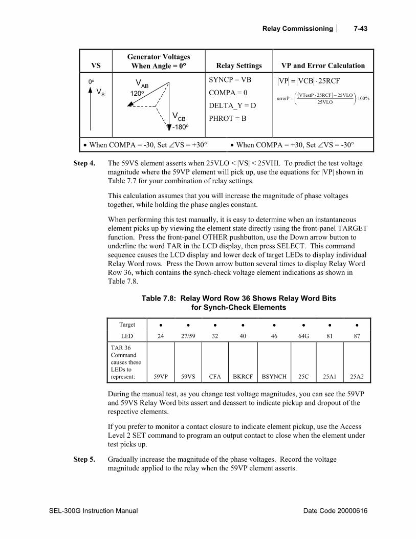
Relay Commissioning 7-43
SEL-300G Instruction Manual Date Code 20000616
VS
Generator Voltages When Angle = 0°°°°
Relay Settings
VP and Error Calculation
0o
VS
VAB120o
-180o
VCB
SYNCP = VB
COMPA = 0
DELTA_Y = D
PHROT = B
RCF25VCBVP ⋅=
( ) %100VLO25
VLO25RCF25VTestPerrorP ⋅
−⋅=
• When COMPA = -30, Set ∠VS = +30° • When COMPA = +30, Set ∠VS = -30°
Step 4. The 59VS element asserts when 25VLO < |VS| < 25VHI. To predict the test voltage magnitude where the 59VP element will pick up, use the equations for |VP| shown in Table 7.7 for your combination of relay settings.
This calculation assumes that you will increase the magnitude of phase voltages together, while holding the phase angles constant.
When performing this test manually, it is easy to determine when an instantaneous element picks up by viewing the element state directly using the front-panel TARGET function. Press the front-panel OTHER pushbutton, use the Down arrow button to underline the word TAR in the LCD display, then press SELECT. This command sequence causes the LCD display and lower deck of target LEDs to display individual Relay Word rows. Press the Down arrow button several times to display Relay Word Row 36, which contains the synch-check voltage element indications as shown in Table 7.8.
Table 7.8: Relay Word Row 36 Shows Relay Word Bits for Synch-Check Elements
Target •••• •••• •••• •••• •••• •••• •••• ••••
LED 24 27/59 32 40 46 64G 81 87
TAR 36 Command causes these LEDs to represent:
59VP
59VS
CFA
BKRCF
BSYNCH
25C
25A1
25A2
During the manual test, as you change test voltage magnitudes, you can see the 59VP and 59VS Relay Word bits assert and deassert to indicate pickup and dropout of the respective elements.
If you prefer to monitor a contact closure to indicate element pickup, use the Access Level 2 SET command to program an output contact to close when the element under test picks up.
Step 5. Gradually increase the magnitude of the phase voltages. Record the voltage magnitude applied to the relay when the 59VP element asserts.

Relay Commissioning
Date Code 2000616 SEL-300G Instruction Manual
7-44
59VP asserted when phase voltage magnitude equaled: ________ V secondary (VTestP).
Step 6. Gradually increase the magnitude of the synch voltage. Record the voltage magnitude applied to the relay when the 59VS element asserts.
59VS asserted when synch voltage magnitude equaled: ________ V secondary (VTestS).
Use the equation shown in the appropriate area of Table 7.7 to calculate the 59VP element error.
errorP = _________ %
Use the equation below to calculate the 59VS element error:
%100VLO25
VLO25VtestSerrorS ⋅
−=
errorS = _________ %
Slip Frequency Accuracy Test
Note: This procedure uses the setup from the voltage element accuracy test. Perform the voltage element accuracy test before proceeding with the slip frequency accuracy test.
Step 1. Configure the voltage test sources to apply balanced, three-phase voltages and synch voltage with magnitudes and phase angles as used in the voltage element accuracy test.
Step 2. Set the synch voltage source frequency equal to the FNOM nominal frequency setting. The SEL-300G Relay defines slip frequency positive when the generator frequency is greater than system frequency. The slip frequency element, SF, asserts when:
25SLO < (Generator Frequency) - (System Frequency) < 25SHI Hz
When performing this test manually, it is easy to determine when the slip frequency element picks up by viewing the element state directly using the front-panel TARGET function. Press the front-panel OTHER pushbutton, use the Down arrow button to underline the word TAR in the LCD display, then press SELECT. This command sequence causes the LCD display and lower deck of target LEDs to display individual Relay Word rows. Press the Down arrow button several times to display Relay Word Row 37, which contains the slip frequency element indications as shown in Table 7.9.
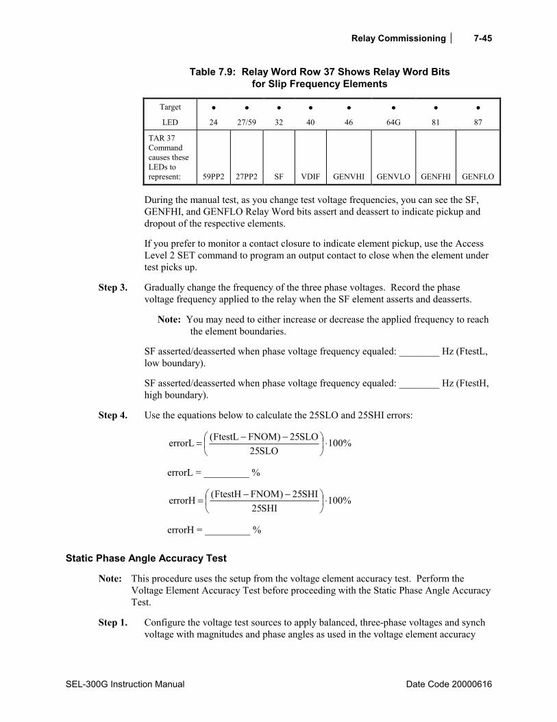
Relay Commissioning 7-45
SEL-300G Instruction Manual Date Code 20000616
Table 7.9: Relay Word Row 37 Shows Relay Word Bits for Slip Frequency Elements
Target •••• •••• •••• •••• •••• •••• •••• ••••
LED 24 27/59 32 40 46 64G 81 87
TAR 37 Command causes these LEDs to represent:
59PP2
27PP2
SF
VDIF
GENVHI
GENVLO
GENFHI
GENFLO
During the manual test, as you change test voltage frequencies, you can see the SF, GENFHI, and GENFLO Relay Word bits assert and deassert to indicate pickup and dropout of the respective elements.
If you prefer to monitor a contact closure to indicate element pickup, use the Access Level 2 SET command to program an output contact to close when the element under test picks up.
Step 3. Gradually change the frequency of the three phase voltages. Record the phase voltage frequency applied to the relay when the SF element asserts and deasserts.
Note: You may need to either increase or decrease the applied frequency to reach the element boundaries.
SF asserted/deasserted when phase voltage frequency equaled: ________ Hz (FtestL, low boundary).
SF asserted/deasserted when phase voltage frequency equaled: ________ Hz (FtestH, high boundary).
Step 4. Use the equations below to calculate the 25SLO and 25SHI errors:
%100SLO25
SLO25)FNOMFtestL(errorL ⋅
−−=
errorL = _________ %
%100SHI25
SHI25)FNOMFtestH(errorH ⋅
−−=
errorH = _________ %
Static Phase Angle Accuracy Test
Note: This procedure uses the setup from the voltage element accuracy test. Perform the Voltage Element Accuracy Test before proceeding with the Static Phase Angle Accuracy Test.
Step 1. Configure the voltage test sources to apply balanced, three-phase voltages and synch voltage with magnitudes and phase angles as used in the voltage element accuracy

Relay Commissioning
Date Code 2000616 SEL-300G Instruction Manual
7-46
test. Set the voltage source frequencies equal to the FNOM nominal frequency setting.
Step 2. The SEL-300G Relay defines voltage phase angle difference positive when VP leads VS. The 25A1, 25A2 angle elements use the magnitude of the phase angle difference rather than the absolute phase angle difference. That is, setting 25ANG2 = 10° defines a window ±10° from VS. The CFA element asserts when the magnitude of the phase angle difference is greater than the CFANGLE setting. When SLIP equals 0, the 25C element asserts when the absolute phase angle difference equals the CANGLE setting.
When performing this test manually, it is easy to determine when the angle elements pick up by viewing the element states directly using the front-panel TARGET function. Press the front-panel OTHER pushbutton, use the Down arrow button to underline the word TAR in the LCD display, then press SELECT. This command sequence causes the LCD display and lower deck of target LEDs to display individual Relay Word rows. Press the Down arrow button several times to display Relay Word Row 36, which contains the angle element indications as shown in Table 7.10.
Table 7.10: Relay Word Row 36 Shows Relay Word Bits for Angle Elements
Target •••• •••• •••• •••• •••• •••• •••• ••••
LED 24 27/59 32 40 46 64G 81 87
TAR 36 Command causes these LEDs to represent:
59VP
59VS
CFA
BKRCF
BSYNCH
25C
25A1
25A2
During the manual test, as you change test voltage phase angles, you can see the CFA, 25C, 25A1, and 25A2 Relay Word bits assert and deassert to indicate pickup and dropout of the respective elements.
If you prefer to monitor a contact closure to indicate element pickup, use the Access Level 2 SET command to program an output contact to close when the element under test picks up.
Step 3. Gradually change the VS voltage phase angle. Reverse the sign of the phase angle and record the result when the CFA, 25C, 25A1, and 25A2 elements assert and deassert. For instance, if 25C asserts when the VS phase angle is -10°, VP is leading VS by 10°, so the recorded result should be +10° rather than -10°.
25C asserted when voltage phase angle equaled: ________ (25Ctest). 25A1 asserted when voltage phase angle equaled: ________ (25A1test1). 25A1 deasserted when voltage phase angle equaled: ________ (25A1test2). 25A2 asserted when voltage phase angle equaled: ________ (25A2test1). 25A2 deasserted when voltage phase angle equaled: ________ (25A2test2). CFA asserted when voltage phase angle equaled: ________ (CFAtest1). CFA deasserted when voltage phase angle equaled: ________ (CFAtest2).

Relay Commissioning 7-47
SEL-300G Instruction Manual Date Code 20000616
Step 4. Calculate the phase angle error by adding the COMPA setting to the test result, then subtract the expected test phase angle (element setting).
Undervoltage (27) Elements
Equipment Needed
• SEL-300G Relay under test. • Two- or Three-Phase AC Voltage Test Source with adjustable magnitude and phase angle. • PC with terminal emulation software and appropriate serial cable to connect the PC-COM
port to the relay.
Test Source Connections
When DELTA_Y = Y, connect the voltage sources according to Figure 7.9. When DELTA_Y = D, connect the voltage sources according to Figure 7.10. Current sources are not needed for this test.
Basic Element Operation
The SEL-300G Relay offers a variety of phase, positive-sequence, and phase-to-phase undervoltage elements.
See Section 2: Relay Element Settings for complete descriptions of the available under- and overvoltage elements.
Element Pickup Accuracy Test
Step 1. Connect the voltage source(s) to the VA, VB, and VC voltage inputs referring to Figure 7.9 or Figure 7.10.
Step 2. Using the front-panel or serial port SHO command, note the settings associated with the voltage element under test.
Step 3. These element pickup settings are made directly in secondary volts, so they will pick up when the applied voltage magnitude is equal to the pickup setting.
Vop = ________ V secondary
When performing this test manually, it is easy to determine when an instantaneous element picks up by viewing the element state directly using the front-panel TARGET function. Press the front-panel OTHER pushbutton, use the Down arrow button to underline the word TAR in the LCD display, then press SELECT. This command sequence causes the LCD display and lower deck of target LEDs to display individual Relay Word rows. Press the Down arrow button several times to display the Relay Word row which contains the pickup indication for the voltage element under test. See TARGET Command in Section 10: Serial Port Communications and Commands for additional details.
Relay Commissioning
Date Code 2000616 SEL-300G Instruction Manual
7-48
During the manual test, as you change the test voltage magnitude, you can see Relay Word bits assert and deassert to indicate pickup and dropout of the respective elements.
If you prefer to monitor a contact closure to indicate element pickup, use the Access Level 2 SET command to program an output contact to close when the element under test picks up.
Step 4. When DELTA_Y = Y, test the 27Pn elements, apply nominal (VNOM/1.73), balanced voltages to all three phases. Gradually decrease the magnitude of one-phase voltage. Record the voltage magnitude applied to the relay when the undervoltage element under test picks up.
To test the 27V1 or 27PPn elements, apply nominal, balanced voltages to all three phases. Gradually decrease the magnitudes of all three voltages. Record the voltage magnitude applied to the relay when the undervoltage element under test picks up.
Vtest = ________ V secondary
When DELTA_Y = Y, use the equation below to calculate the 27Pn and 27V1 element error:
%100Vop
VopVtesterror ⋅
−=
When DELTA_Y = D, use the equation below to calculate the 27V1 element error:
%100Vop
Vop732.1
Vtest
error ⋅
−=
error = _________ %
When DELTA_Y = Y, use the equation below to calculate the 27PPn element error:
%100Vop
Vop732.1Vtesterror ⋅
−⋅=
When DELTA_Y = D, use the equation below to calculate the 27PPn element error:
%100Vop
VopVtesterror ⋅
−=
error = _________ %
Relay Commissioning 7-49
SEL-300G Instruction Manual Date Code 20000616
Reverse/Low-Forward Power (32) Element
Equipment Needed
• SEL-300G Relay under test. • Two- or Three-Phase AC Voltage and Current Test Source, with adjustable magnitude and
phase angle. • PC with terminal emulation software and appropriate serial cable to connect the PC-COM
port to the relay.
Test Source Connections
When DELTA_Y = Y, connect the voltage sources according to Figure 7.9. When DELTA Y= D, connect the voltage sources according to Figure 7.10.
Basic Element Operation
The SEL-300G Relay reverse/low-forward power element is designed to detect generator motoring conditions and provide an alarm or trip. The relay measures the generator phase voltages and currents, then calculates the three-phase power in per unit of the generator nominal power using the equation:
)cos(INOMVNOM732.1
IpVp3Power Θ⋅
⋅⋅⋅⋅
= per unit
Where: |Vp| = measured generator phase voltage magnitude |Ip| = measured generator phase current magnitude VNOM = nominal generator phase-to-phase voltage (Relay Global Setting) INOM = nominal generator phase current (Relay Global Setting) Θ = phase angle between phase voltage and phase current (positive when
current lags voltage)
The 32P1 and 32P2 elements are definite-time, reverse/low-forward power elements. If the measured three-phase power is less than the element setting, the relay asserts the 32P1 or 32P2 Relay Word bit to logical 1. If this condition continues for the associated definite-time delay, the relay asserts the 32P1T or 32P2T Relay Word bit to logical 1 (see Section 2: Relay Element Settings for a complete description of the elements).
Element Operating Accuracy Test, DELTA_Y = Y
Step 1. Make the test source connections according to Figure 7.9.
Step 2. Using the front-panel or serial port SHO command, note the settings associated with the relay reverse power elements:
Relay Commissioning
Date Code 2000616 SEL-300G Instruction Manual
7-50
VNOM = ________ volts (nominal phase-to-phase voltage) INOM = ________ amps (nominal generator phase current) E32 = Y (setting enables the reverse/low-forward power elements) 32P1P = ________ per unit reverse power (element pickup setting) 32P1D = ________ seconds (element definite-time delay) 32P2P = ________ per unit reverse power (element pickup setting) 32P2D = ________ seconds (element definite-time delay) 32PTC = __________________________________________________________
Torque-Control Setting (elements are enabled when 32PTC = logical 1)
Using the front-panel or serial port SHO G command, note the global PHROT setting:
PHROT = ________ ABC or ACB (generator phase rotation)
Step 3. This element is easiest to test by changing the test current while holding the phase-to-phase test voltage equal to VNOM. Set the test source voltage magnitudes equal to VNOM/1.732. Set the test source voltage phase angles as shown in Figure 7.7.
Set the test source current phase angles depending on the sign of the power setting for the element under test as follows:
When setting 32PnP > 0.0, set angle Ia = angle Va° set angle Ib = angle Vb° set angle Ic = angle Vc°
When setting 32PnP < 0.0, set angle Ia = angle Va - 180° set angle Ib = angle Vb - 180° set angle Ic = angle Vc - 180°
Use the following equation to predict the current magnitude where the element will operate.
INOMPnP32Iopn ⋅= A secondary Iop1 = ________ A secondary Iop2 = ________ A secondary
Table 7.11 summarizes the phase angle and operate relationships represented in Figure 7.16.
Table 7.11: Reverse Power Element Test Signal Summary
When 32PnP < 0: When 32PnP > 0:
Set the phase angle of Ip equal to the phase angle of Vp - 180°
Set the phase angle of Ip equal to the phase angle of Vp
Relay Word bit 32Pn is logical 1 when |Ip| > |Iopn|
Relay Word bit 32Pn is logical 1 when |Ip| < |Iopn|
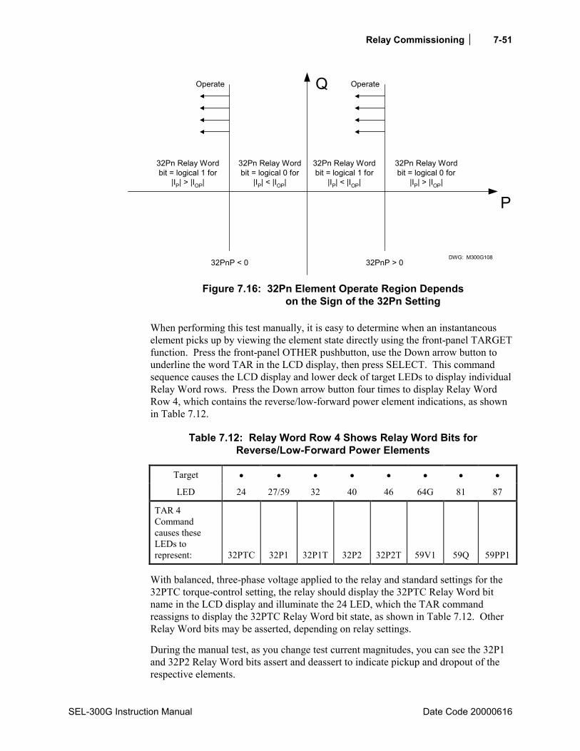
Relay Commissioning 7-51
SEL-300G Instruction Manual Date Code 20000616
32Pn Relay Wordbit = logical 1 for
|IP| < |IOP|
32Pn Relay Wordbit = logical 0 for
|IP| < |IOP|
Q
32Pn Relay Wordbit = logical 0 for
|IP| > |IOP|
32Pn Relay Wordbit = logical 1 for
|IP| > |IOP|
32PnP > 032PnP < 0
P
DWG: M300G108
OperateOperate
Figure 7.16: 32Pn Element Operate Region Depends
on the Sign of the 32Pn Setting
When performing this test manually, it is easy to determine when an instantaneous element picks up by viewing the element state directly using the front-panel TARGET function. Press the front-panel OTHER pushbutton, use the Down arrow button to underline the word TAR in the LCD display, then press SELECT. This command sequence causes the LCD display and lower deck of target LEDs to display individual Relay Word rows. Press the Down arrow button four times to display Relay Word Row 4, which contains the reverse/low-forward power element indications, as shown in Table 7.12.
Table 7.12: Relay Word Row 4 Shows Relay Word Bits for Reverse/Low-Forward Power Elements
Target • • • • • • • •
LED 24 27/59 32 40 46 64G 81 87
TAR 4 Command causes these LEDs to represent:
32PTC
32P1
32P1T
32P2
32P2T
59V1
59Q
59PP1
With balanced, three-phase voltage applied to the relay and standard settings for the 32PTC torque-control setting, the relay should display the 32PTC Relay Word bit name in the LCD display and illuminate the 24 LED, which the TAR command reassigns to display the 32PTC Relay Word bit state, as shown in Table 7.12. Other Relay Word bits may be asserted, depending on relay settings.
During the manual test, as you change test current magnitudes, you can see the 32P1 and 32P2 Relay Word bits assert and deassert to indicate pickup and dropout of the respective elements.
Relay Commissioning
Date Code 2000616 SEL-300G Instruction Manual
7-52
If you prefer to monitor a contact closure to indicate element pickup, use the Access Level 2 SET command to program an output contact to close when the element under test picks up.
Step 4. Set the test source current phase angles appropriately to test the 32P1 pickup, based on the relay settings and the information above. Turn on the current test sources and gradually increase the magnitude of all three phase currents. Record the current magnitude applied to the relay when the instantaneous element under test asserts/deasserts. Record the current magnitude and turn off the current test sources.
Itest1= _______ A secondary
If necessary, change the test source current phase angles to test the 32P2 pickup. Turn on the current test sources and gradually increase the magnitude of all three-phase currents. Record the current magnitude applied to the relay when the instantaneous element under test asserts/deasserts. Record the current magnitude and turn off the current test sources.
Itest2= _______ A secondary
Step 5. Use the equation below to calculate the element error:
%100PnP32
PnP32INOMItestn
errorn ⋅
−=
error1 = _________ % error2 = _________ %
Element Operating Accuracy Test, DELTA_Y = D
Step 1. Make the test source connections according to Figure 7.10.
Step 2. Using the front-panel or serial port SHO command, note the settings associated with the relay reverse power elements:
VNOM = ________ volts (nominal phase-to-phase voltage) INOM = ________ amps (nominal generator phase current) E32 = Y (setting enables the reverse/low-forward power elements) 32P1P = ________ per unit reverse power (element pickup setting) 32P1D = ________ seconds (element definite-time delay) 32P2P = ________ per unit reverse power (element pickup setting) 32P2D = ________ seconds (element definite-time delay) 32PTC = __________________________________________________________
Torque-Control Setting (elements are enabled when 32PTC = logical 1)

Relay Commissioning 7-53
SEL-300G Instruction Manual Date Code 20000616
Using the front-panel or serial port SHO G command, note the global PHROT setting:
PHROT = ________ ABC or ACB (generator phase rotation)
Step 3. This element is easiest to test by changing the test current while holding the phase-to-phase test voltages equal to VNOM. Set the test source voltage magnitudes equal to VNOM. Set the test source voltage phase angles as shown in Figure 7.8.
Set the test source current phase angles depending on the sign of the power setting for the element under test as follows:
When setting 32PnP > 0.0, set angle Ia = angle 0° set angle Ib = angle -120° (120° if PHROT = C) set angle Ic = angle 120° (-120° if PHROT = C)
When setting 32PnP < 0.0, set angle Ia = angle 180° set angle Ib = angle 60° (-60° if PHROT = C) set angle Ic = angle -60° (60° if PHROT = C)
Use the following equation to predict the current magnitude where the element will operate.
Iopn = 32PnP INOM A secondary Iop1 = ___________ A secondary Iop2 = ___________ A secondary
Table 7.11 summarizes the phase angle and operate relationships represented in Figure 7.16.
When performing this test manually, it is easy to determine when an instantaneous element picks up by viewing the element state directly using the front-panel TARGET function. Press the front-panel OTHER pushbutton, use the Down arrow button to underline the word TAR in the LCD display, then press SELECT. This command sequence causes the LCD display and lower deck of target LEDs to display individual Relay Word rows. Press the Down arrow button four times to display Relay Word Row 4, which contains the reverse/low-forward power element indications, as shown in Table 7.12.
With balanced voltage applied to the relay and standard settings for the 32PTC torque-control setting, the relay should display the 32PTC Relay Word bit name in the LCD display and illuminate the 24 LED, which the TAR command reassigns to display the 32PTC Relay Word bit state, as shown in Table 7.12. Other Relay Word bits may be asserted, depending on relay settings.
During the manual test, as you change test current magnitudes, you can see the 32P1 and 32P2 Relay Word bits assert and deassert to indicate pickup and dropout of the respective elements.
If you prefer to monitor a contact closure to indicate element pickup, use the Access Level 2 SET command to program an output contact to close when the element under test picks up.
Relay Commissioning
Date Code 2000616 SEL-300G Instruction Manual
7-54
Step 4. Set the test source current phase angles appropriately to test the 32P1 pickup, based on the relay settings and the information above. Turn on the current test sources and gradually increase the magnitude of all three phase currents. Record the current magnitude applied to the relay when the instantaneous element under test asserts/deasserts. Record the current magnitude and turn off the current test sources.
Itest1= _______ A secondary
If necessary, change the test source current phase angles to test the 32P2 pickup. Turn on the current test sources and gradually increase the magnitude of all three-phase currents. Record the current magnitude applied to the relay when the instantaneous element under test asserts/deasserts. Record the current magnitude and turn off the current test sources.
Itest2= _______ A secondary
Step 5. Use the equation below to calculate the element error:
%100PnP32
PnP32INOMItestn
errorn ⋅
−=
error1 = _________ % error2 = _________ %
Element Timing Accuracy Test
Note: This procedure uses the setup from the element pickup accuracy tests above. Perform the element pickup accuracy test before proceeding with the element timing accuracy test.
The object of the element timing accuracy test is to apply predefined signals to the relay and measure the element response time. There are two methods available to measure the element response time, SER review and output contact operation. These methods are described in Test Methods beginning on page 7-4.
32 Element Definite-Time Delay Accuracy Test
The 32P1T Relay Word bit asserts 32P1D seconds after the 32P1 element asserts. The element pickup accuracy test verified the accuracy of the 32P1P and 32P2P settings. This test applies signals within the 32P1 and 32P2 element operate regions and measures the element definite operating time.
Step 1. Based on the two timing test descriptions above (SER or output contact driving an external timer), select one method and make the settings and connections necessary to support the selection. Configure the voltage test sources to apply balanced voltages with magnitudes and phase angles as used for the element accuracy tests above (go to Step 2 or Step 3). Set the current phase angles as you did in the element accuracy tests.
Relay Commissioning 7-55
SEL-300G Instruction Manual Date Code 20000616
Step 2. For 32PnP < 0:
Configure the current test sources to apply balanced, three-phase currents with magnitudes equal to 1.1⋅Iopn, as determined by the test above. The element time is calculated from the instant current signals are applied to the relay until the 32PnT Relay Word bit asserts. Record the element operating time, Ttestn.
Step 3. For 32PnP > 0:
Configure the current test sources to apply balanced, three-phase currents with magnitudes equal to 1.1⋅Iopn, as determined by the element accuracy test above, and turn on the current test sources. The element time is calculated from the instant current signals are removed from the relay until the 32PnT Relay Word bit asserts. Record the element operating time, Ttestn.
Step 4. Calculate the relay timing error using the equation:
%100PnD32
PnD32Ttestnerrorn ⋅
−=
error1 = _________ % error2 = _________ %
Loss-of-Field (40) Element
Equipment Needed
• SEL-300G Relay under test. • Two- or Three-Phase AC Voltage and Current Test Source, with adjustable magnitude and
phase angle. • PC with terminal emulation software and appropriate serial cable to connect the PC-COM
port to the relay.
Test Source Connections
When DELTA_Y = Y, connect the voltage and current sources according to Figure 7.9. When DELTA = D, connect the voltage and current sources according to Figure 7.10.
Basic Element Operation
The SEL-300G Relay loss-of-field element consists of two offset phase mho zones that operate on the basis of positive-sequence impedance.
The 40Z1 and 40Z2 elements are definite-time, offset mho elements that operate using positive-sequence impedance. If the measured positive-sequence impedance falls within the mho element zone, the relay asserts the 40Z1 or 40Z2 Relay Word bit to logical 1. If this condition continues for the associated definite-time delay, the relay asserts the 40Z1T or 40Z2T Relay Word bit to logical 1 (see Section 2: Relay Element Settings for a complete element description).

Relay Commissioning
Date Code 2000616 SEL-300G Instruction Manual
7-56
Element Operating Accuracy Test
Step 1. Make test source connections according to Figure 7.9 or Figure 7.10.
Step 2. Using the front-panel or serial port SHO command, note the settings associated with the relay loss-of-field elements:
VNOM = ________ volts (nominal phase-to-phase voltage) E40 = Y (setting enables the loss-of-field elements) 40Z1P = ________ Ω secondary (Zone 1 Mho Element diameter setting) 40XD1 = ________ Ω secondary (Zone 1 Mho Element offset setting) 40Z1D = ________ seconds (Zone 1 element definite-time delay) 40Z2P = ________ Ω secondary (Zone 2 Mho Element diameter setting) 40XD2 = ________ Ω secondary (Zone 2 Mho Element offset setting) 40Z2D = ________ seconds (Zone 2 element definite-time delay) 40DIR = ________ degrees (Zone 2 directional supervision, only appears if
40XD2 > 0.0) 40ZTC = __________________________________________________________
Torque-Control Setting (elements are enabled when 40ZTC = logical 1)
Using the front-panel or serial port SHO G command, note the global PHROT and DELTA_Y setting:
PHROT = ________ ABC or ACB (generator phase rotation) DELTA_Y = ________ Y or D (generator pt connection)
Step 3. This element is easiest to test by changing the test current while holding the phase-to-phase test voltage equal to VNOM. Set the test source voltage magnitudes equal to VNOM/1.732 (DELTA_Y = Y) or VNOM (DELTA_Y = D). Set the test source voltage phase angles as shown in Figure 7.7 or Figure 7.8.
Set the test source current phase angles as follows:
When setting PHROT = ABC, set angle Ia = 90° set angle Ib = -30° set angle Ic = -150°
When setting PHROT = ACB, set angle Ia = 90° set angle Ib = -150° set angle Ic = -30°
Refer to Figure 7.17 and Figure 7.18. In these figures, the phase current necessary to apply the test at the point indicated by the vector TestXAn is calculated using the following equation:
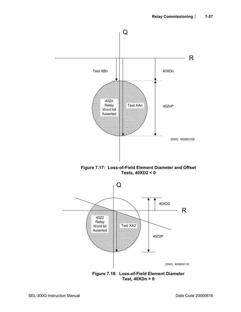
Relay Commissioning 7-57
SEL-300G Instruction Manual Date Code 20000616
DWG: M300G109
Test XAn
Test XBn
40ZnRelay
Word bitAsserted
40ZnP
40XDn
Q
R
Figure 7.17: Loss-of-Field Element Diameter and Offset
Tests, 40XD2 < 0
DWG: M300G110
Test XA2
40Z2Relay
Word bitAsserted
40XD2
Q
R
40Z2P
Figure 7.18: Loss-of-Field Element Diameter
Test, 40XDn > 0

Relay Commissioning
Date Code 2000616 SEL-300G Instruction Manual
7-58
( )XDn40ZnP40VaIopXAn−
= A secondary (DELTA_Y = Y)
( )XDn40ZnP403VaIopXAn
−⋅= A secondary (DELTA_Y = D)
IopXA1 = ________ A secondary IopXA2 = ________ A secondary
In Figure 7.17 you can calculate the phase current necessary to apply the test at the point indicated by the vector TestXBn using the equation:
( )XDn40VaIopXBn = A secondary (DELTA_Y = Y)
( )XDn403VaIopXBn
⋅= A secondary (DELTA_Y = D)
IopXB1 = ________ A secondary IopXB2 = ________ A secondary
When 40XD2 is positive, this second point on the mho circle is not available to test.
When performing this test manually, it is easy to determine when an instantaneous element picks up by viewing the element state directly using the front-panel TARGET function. Press the front-panel OTHER pushbutton, use the Down arrow button to underline the word TAR in the LCD display, then press SELECT. This command sequence causes the LCD display and lower deck of target LEDs to display individual Relay Word rows. Press the Down arrow button five times to display Relay Word Row 5, which contains the loss-of-field element indications, as shown in Table 7.13.
Table 7.13: Relay Word Row 5 Shows Relay Word Bits for Loss-of-Field Elements
Target • • • • • • • •
LED 24 27/59 32 40 46 64G 81 87
TAR 5 Command causes these LEDs to represent:
40ZTC
40Z1
40Z1T
40Z2
40Z2T
*
SG1
SG2
With balanced, three-phase voltage applied to the relay and standard settings for the 40ZTC torque-control setting, the relay should display the 40ZTC Relay Word bit name in the LCD display and illuminate the 24 LED, which the TAR command reassigns to display the 40ZTC Relay Word bit state, as shown in Table 7.13. Either SG1 or SG2 will be asserted, depending on which relay setting group is active.
During the manual test, as you change test current magnitudes, you can see the 40Z1 and 40Z2 Relay Word bits assert and deassert to indicate pickup and dropout of the respective elements.

Relay Commissioning 7-59
SEL-300G Instruction Manual Date Code 20000616
If you prefer to monitor a contact closure to indicate element pickup, use the Access Level 2 SET command to program an output contact to close when the element under test picks up.
Step 4. Turn on the current test sources and gradually increase the magnitude of all three phase currents. Record the applied current magnitude when the Zone 1 and Zone 2 instantaneous elements assert.
ItestXA1 = ________ A secondary ItestXA2 = ________ A secondary
Continue to increase the phase current magnitudes until the 40Z1 Relay Word bit deasserts. This point corresponds to the TestXB1 in Figure 7.17. Record the magnitude of the test currents at this point.
ItestXB1 = ________ A secondary
When 40XD2 is negative, also record the phase current magnitudes when the 40Z2 Relay Word bit deasserts.
ItestXB2 = ________ A secondary
When 40XD2 is positive, this second point on the mho circle is not available to test.
Step 5. Use the equations below to calculate the element error:
%100XDn40ZnP40
)XDn40ZnP40(ItestXAn
Va
errorXAn ⋅
−
−−= (DELTA_Y = Y)
%100XDn40ZnP40
)XDn40ZnP40(3ItestXAn
Va
errorXAn ⋅
−
−−⋅= (DELTA_Y = D)
errorXA1 = _________ % errorXA2 = _________ %
%100XDn40
XDn40ItestXBn
Va
errorXBn ⋅
−= (DELTA_Y = Y)
%100XDn40
XDn403ItestXBn
Va
errorXBn ⋅
−⋅= (DELTA_Y = D)
errorXB1 = _________ % errorXB2 = _________ % (applicable when 40XD2 < 0)
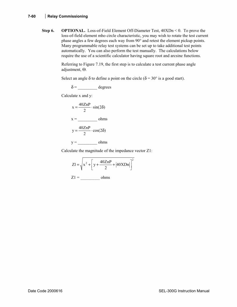
Relay Commissioning
Date Code 2000616 SEL-300G Instruction Manual
7-60
Step 6. OPTIONAL. Loss-of-Field Element Off-Diameter Test, 40XDn < 0. To prove the loss-of-field element mho circle characteristic, you may wish to rotate the test current phase angles a few degrees each way from 90° and retest the element pickup points. Many programmable relay test systems can be set up to take additional test points automatically. You can also perform the test manually. The calculations below require the use of a scientific calculator having square root and arcsine functions.
Referring to Figure 7.19, the first step is to calculate a test current phase angle adjustment, Θ.
Select an angle δ to define a point on the circle (δ = 30° is a good start).
δ = _________ degrees
Calculate x and y:
)2sin(2ZnP40x δ⋅=
x = _________ ohms
)2cos(2ZnP40y δ⋅=
y = _________ ohms
Calculate the magnitude of the impedance vector Z1:
22 XDn40
2ZnP40yx1Z
+++=
Z1 = _________ ohms

Relay Commissioning 7-61
SEL-300G Instruction Manual Date Code 20000616
DWG: M300G111
40ZnP
40XDn
Q
R
Θ
Z1
x
δ°
y
Figure 7.19: Loss-of-Field Element Off-Diameter
Test, 40XDn < 0
=Θ1Z
xarcsinn degrees
Θ = ________ degrees
Set the test source current phase angles as follows:
When setting PHROT = ABC, set angle Ia = 90° + Θ° set angle Ib = -30° + Θ° set angle Ic = -150 ° + Θ°
When setting PHROT = ACB, set angle Ia = 90° + Θ° set angle Ib = -150° + Θ° set angle Ic = -30° + Θ°
Next, calculate the expected pickup current magnitude:
1ZVaIopXA = A secondary (DELTA_Y = Y)
1Z3VaIopXA
⋅= A secondary (DELTA_Y = D)
IopXA = ________ A secondary
For each test phase angle, increase the three-phase current magnitudes together until the element under test picks up. Record the test current magnitude.
ItestXA = ________ A secondary

Relay Commissioning
Date Code 2000616 SEL-300G Instruction Manual
7-62
You can use these equations to test Zone 1 and Zone 2 elements having negative offsets.
Use the equations below to calculate the element error:
%1001Z
1ZItestXAn
Va
errorXA ⋅
−= (DELTA_Y = Y)
%1001Z
1Z3ItestXAn
Va
errorXA ⋅
−⋅= (DELTA_Y = D)
errorXA = _________ %
If you wish, you may repeat the test, rotating the test current phase angles by (-Θn°).
Element Timing Accuracy Test
Note: This procedure uses the setup from the Element Pickup Accuracy Test. Perform the Element Pickup Accuracy Test before proceeding with the Element Timing Accuracy Test.
The object of the Element Timing Accuracy Test is to apply predefined signals to the relay and measure the element response time. There are two methods available to measure the element response time, SER review and output contact operation. These methods are described in Test Methods beginning on page 7-4.
40 Element Definite-Time Delay Accuracy Test
The 40Z1T Relay Word bit asserts 40Z1D seconds after the 40Z1 element asserts. The Element Pickup Accuracy Test verified the accuracy of the loss-of-field element offset and diameter settings. This test applies signals within each zone and measures the element definite operating time.
Step 1. Based on the two timing test descriptions above (SER or output contact driving an external timer), select one method and make the settings and connections necessary to support the selection. Configure the voltage test sources to apply balanced, three-phase voltages with magnitudes from the previous tests.
Step 2. Set the current source phase angles as in Step 3 of the Element Accuracy Test.
Configure the current test sources to apply balanced, three-phase currents with magnitudes greater than 1.1⋅ItestXAn, as determined by the previous test. The element time is calculated from the instant current signals are applied until the 40ZnT Relay Word bit asserts. Record the element operating time, Ttestn.

Relay Commissioning 7-63
SEL-300G Instruction Manual Date Code 20000616
Step 3. Calculate the relay timing error using the equation:
%100ZnD40
ZnD40Ttestnerrorn ⋅
−=
error1 = _________ % error2 = _________ %
Negative-Sequence Overcurrent (46) Element
Equipment Needed
• SEL-300G Relay under test. • Single-Phase AC Current Test Source, with adjustable magnitude. • PC with terminal emulation software and appropriate serial cable to connect the PC-COM
port to the relay.
Test Source Connections
Connect the current source according to Figure 7.20.
DWG: M300G114
IA
Single-Phase Current Source
Z01IA
Z02 Z03 Z04 Z05 Z06 Z07 Z08 Z09 Z10 Z11 Z12IB IC IN
VA
Z13 Z14
VB VC N VN NN
Relay Rear-Panel Voltage and Current Inputs
Figure 7.20: Single Current Source Test Connection
Basic Element Operation
The SEL-300G Relay negative-sequence overcurrent element is designed to detect current unbalance in the generator. The relay measures the generator phase currents, calculates the negative-sequence current, then operates definite-time and inverse-time protection elements.
The 46Q1 element is a definite-time, negative-sequence overcurrent element typically applied as an alarm. If the measured negative-sequence current is above the 46Q1P setting, the relay asserts the 46Q1 Relay Word bit to logical 1. If this condition continues for 46Q1D seconds, the relay

Relay Commissioning
Date Code 2000616 SEL-300G Instruction Manual
7-64
asserts the 46Q1T Relay Word bit to logical 1. When the unbalance condition vanishes, the relay deasserts both Relay Word bits to logical 0.
The 46Q2 element is an inverse-time negative-sequence overcurrent element with an I22t
operating characteristic. See Section 2: Relay Element Settings for a complete description of the element.
Element Pickup Accuracy Test
Step 1. Connect the current source to the IA, IB, or IC phase current input.
Step 2. Using the front-panel or serial port SHO command, note the settings associated with the relay negative-sequence overcurrent element:
INOM = ________ amps (nominal phase current) E46 = Y (setting enables the negative-sequence overcurrent
elements) 46Q1P = ________ % negative-sequence current (alarm element pickup setting) 46Q1D = ________ seconds (alarm element definite-time delay) 46Q2P = ________ % negative-sequence current (inverse-time element pickup) 46Q2K = ________ (inverse-time element time-dial) 46QTC = ___________________________________________________________
Torque-Control Setting (elements are enabled when 46QTC = logical 1)
Step 3. To predict the test current magnitude where each element will operate, use equation:
%100INOMQnP463Iopn ⋅⋅= A secondary
Iop1 = ________ A secondary Iop2 = ________ A secondary
Note: With single-phase current applied, measured |I2| = |IA/3|. That is why the applied current, Iopn, is three times the set I2 pickup value.
When performing this test manually, it is easy to determine when an instantaneous element picks up by viewing the element state directly using the front-panel TARGET function. Press the front-panel OTHER pushbutton, use the Down arrow button to underline the word TAR in the LCD display, then press SELECT. This command sequence causes the LCD display and lower deck of target LEDs to display individual Relay Word rows. Press the Down arrow button several times to display Relay Word Row 6, which contains the negative-sequence overcurrent element indications, as shown in Table 7.14.
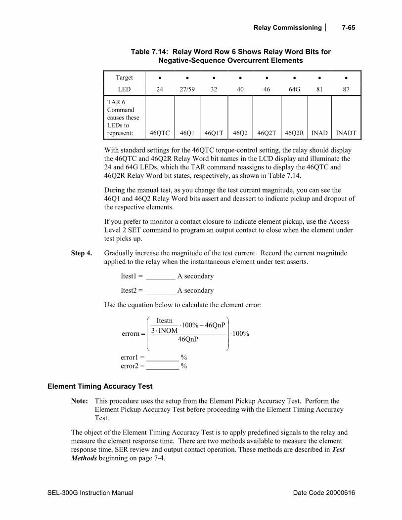
Relay Commissioning 7-65
SEL-300G Instruction Manual Date Code 20000616
Table 7.14: Relay Word Row 6 Shows Relay Word Bits for Negative-Sequence Overcurrent Elements
Target • • • • • • • •
LED 24 27/59 32 40 46 64G 81 87
TAR 6 Command causes these LEDs to represent:
46QTC
46Q1
46Q1T
46Q2
46Q2T
46Q2R
INAD
INADT
With standard settings for the 46QTC torque-control setting, the relay should display the 46QTC and 46Q2R Relay Word bit names in the LCD display and illuminate the 24 and 64G LEDs, which the TAR command reassigns to display the 46QTC and 46Q2R Relay Word bit states, respectively, as shown in Table 7.14.
During the manual test, as you change the test current magnitude, you can see the 46Q1 and 46Q2 Relay Word bits assert and deassert to indicate pickup and dropout of the respective elements.
If you prefer to monitor a contact closure to indicate element pickup, use the Access Level 2 SET command to program an output contact to close when the element under test picks up.
Step 4. Gradually increase the magnitude of the test current. Record the current magnitude applied to the relay when the instantaneous element under test asserts.
Itest1 = ________ A secondary
Itest2 = ________ A secondary
Use the equation below to calculate the element error:
%100QnP46
QnP46%100INOM3
Itestn
errorn ⋅
−⋅⋅=
error1 = _________ % error2 = _________ %
Element Timing Accuracy Test
Note: This procedure uses the setup from the Element Pickup Accuracy Test. Perform the Element Pickup Accuracy Test before proceeding with the Element Timing Accuracy Test.
The object of the Element Timing Accuracy Test is to apply predefined signals to the relay and measure the element response time. There are two methods available to measure the element response time, SER review and output contact operation. These methods are described in Test Methods beginning on page 7-4.
Relay Commissioning
Date Code 2000616 SEL-300G Instruction Manual
7-66
46Q1D Time-Delay Accuracy Test
The 46Q1T Relay Word bit asserts 46Q1D seconds after the measured negative-sequence current exceeds the 46Q1P setting. The Element Pickup Accuracy Test verified the accuracy of the 46Q1P setting. This test applies signals greater than the 46Q1P setting and measures the element definite operating time.
Step 1. Based on the two timing test descriptions above (SER or output contact driving an external timer), select one method and make the settings and connections necessary to support the selection. Configure the current test source to apply single-phase current with magnitude equal to 1.1 ⋅ Itest1, as measured by the 46Q1P test performed above.
Step 2. Expect 46Q1T to assert 46Q1D seconds after the test signals are applied.
Step 3. Apply the test current calculated in Step 1 and record the element operating time, Ttest1. Remove the test current.
Ttest1 = _________ seconds
Step 4. Calculate the relay timing error using the equation:
%100D1Q46
D1Q461Ttesterror ⋅
−=
error = _________ %
46Q2 Inverse-Time Accuracy Test
The 46Q2 negative-sequence overcurrent element operates as an inverse-time delayed element, as shown in Figure 7.21. This test procedure uses three test points to verify that the element is operating properly.
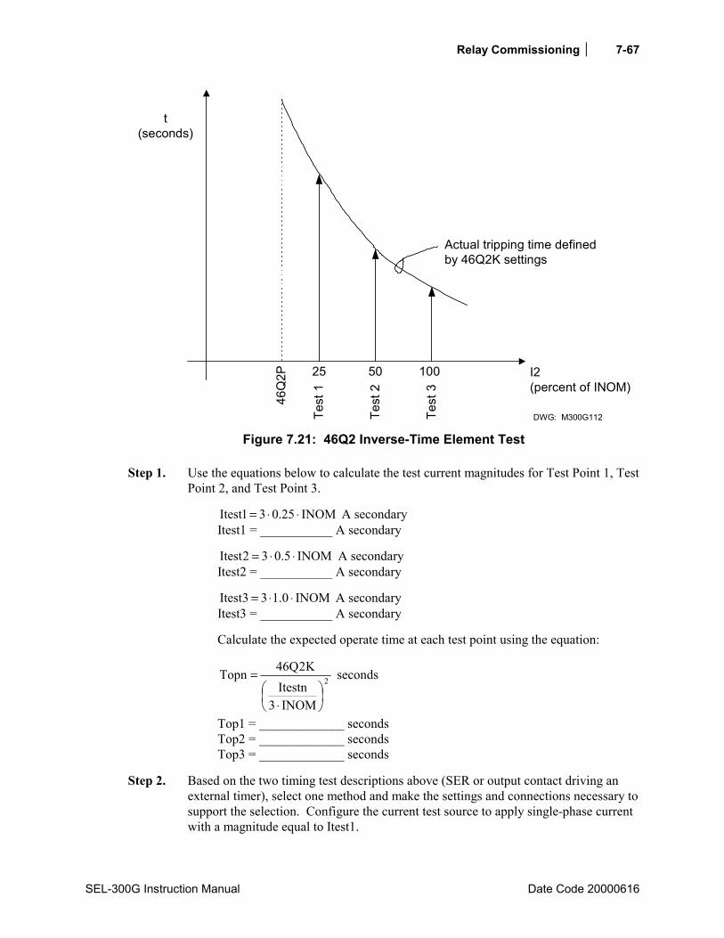
Relay Commissioning 7-67
SEL-300G Instruction Manual Date Code 20000616
t(seconds)
46Q
2P
Test
1
Test
2
Test
3
I2(percent of INOM)
DWG: M300G112
Actual tripping time definedby 46Q2K settings
25 50 100
Figure 7.21: 46Q2 Inverse-Time Element Test
Step 1. Use the equations below to calculate the test current magnitudes for Test Point 1, Test Point 2, and Test Point 3.
INOM25.031Itest ⋅⋅= A secondary Itest1 = ___________ A secondary
INOM5.032Itest ⋅⋅= A secondary Itest2 = ___________ A secondary
INOM0.133Itest ⋅⋅= A secondary Itest3 = ___________ A secondary
Calculate the expected operate time at each test point using the equation:
2
INOM3Itestn
K2Q46Topn
⋅
= seconds
Top1 = _____________ seconds Top2 = _____________ seconds Top3 = _____________ seconds
Step 2. Based on the two timing test descriptions above (SER or output contact driving an external timer), select one method and make the settings and connections necessary to support the selection. Configure the current test source to apply single-phase current with a magnitude equal to Itest1.

Relay Commissioning
Date Code 2000616 SEL-300G Instruction Manual
7-68
Step 3. Apply the test current and record the element operating time, Ttest1. Remove the test current for at least 4 minutes to permit the element to fully reset. Repeat using Itest2 and Itest3.
Ttest1 = _________ seconds Ttest2 = _________ seconds Ttest3 = _________ seconds
Step 4. Calculate the relay timing errors at each test point using the equation:
%100Topn
TopnTtestnerrorn ⋅
−=
error1 = _________ % error2 = _________ % error3 = _________ %
Overcurrent (50/51) Elements
Equipment Needed
• SEL-300G Relay under test. • Single-Phase AC Current Test Source, with adjustable magnitude. • PC with terminal emulation software and appropriate serial cable to connect the PC-COM
port to the relay.
Test Source Connections
Connect the current source according to Figure 7.20.
Basic Element Operation
The SEL-300G Relay offers a variety of phase, residual, and neutral overcurrent elements. These elements offer instantaneous, definite-time, and inverse-time operating characteristics. You can test any of the elements using a single-phase current source.
See Section 2: Relay Element Settings for complete descriptions of the available overcurrent elements.
Element Pickup Accuracy Test
Step 1. Connect the current source to the IA, IB, or IC current input to test phase or residual overcurrent elements. Connect the current source to the IN current input to test neutral overcurrent elements.
Step 2. Using the front-panel or serial port SHO command, note the settings associated with the overcurrent element under test.
Step 3. These overcurrent element pickup settings are made directly in secondary amps, so they will pick up when the applied current magnitude is equal to the pickup setting.
Relay Commissioning 7-69
SEL-300G Instruction Manual Date Code 20000616
Iop = ________ A secondary
When performing this test manually, it is easy to determine when an instantaneous element picks up by viewing the element state directly using the front-panel TARGET function. Press the front-panel OTHER pushbutton, use the Down arrow button to underline the word TAR in the LCD display, then press SELECT. This command sequence causes the LCD display and lower deck of target LEDs to display individual Relay Word rows. Press the Down arrow button several times to display the Relay Word Row which contains the pickup indication for the overcurrent element under test. See TARGET Command in Section 10: Serial Port Communications and Commands for additional details.
During the manual test, as you change the test current magnitude, you can see the Relay Word bits assert and deassert to indicate pickup and dropout of the respective elements.
If you prefer to monitor a contact closure to indicate element pickup, use the Access Level 2 SET command to program an output contact to close when the element under test picks up.
Step 4. Gradually increase the magnitude of the test current. Record the current magnitude applied to the relay when the instantaneous element under test asserts.
Itest = ________ A secondary
Use the equation below to calculate the element error:
%100Iop
IopItesterror ⋅
−=
error = _________ %
Element Timing Accuracy Test
Note: This procedure uses the setup from the Element Pickup Accuracy Test. Perform the Element Pickup Accuracy Test before proceeding with the Element Timing Accuracy Test.
The object of the Element Timing Accuracy Test is to apply predefined signals to the relay and measure the element response time. There are two methods available to measure the element response time, SER review and output contact operation. These methods are described in Test Methods on page 7-4.
Definite Time-Delay Accuracy Test
The definite-time delayed overcurrent element Relay Word bit asserts a settable time after the measured current exceeds the pickup setting. The Element Pickup Accuracy Test verified the accuracy of the pickup setting. This test applies signals greater than the pickup and measures the element definite operating time.
Step 1. Based on the two timing test descriptions above (SER or output contact driving an external timer), select one method and make the settings and connections necessary to

Relay Commissioning
Date Code 2000616 SEL-300G Instruction Manual
7-70
support the selection. Configure the current test source to apply single-phase current with magnitude equal to 1.1 ⋅ Itest, as measured by the previous test.
Step 2. Expect the time delayed Relay Word bit to assert after the test signals are applied. The delay should equal the element definite-time delay setting.
Step 3. Apply the test current calculated in Step 1 and record the element operating time, Ttest. Remove the test current.
Ttest = _________ seconds
Step 4. Calculate the relay timing error using the equation:
%100Setting_Delay
)Setting_Delay(Ttesterror ⋅
−=
error = _________ %
Inverse-Time Accuracy Test
To test overcurrent elements having an inverse-time characteristic, this test defines three test points in the element timing characteristic.
Step 1. Use the equations below to calculate the test current magnitudes for Test Point 1, Test Point 2, and Test Point 3.
Ipickup31Itest ⋅= A secondary Itest1 = ___________ A secondary
Ipickup52Itest ⋅= A secondary Itest2 = ___________ A secondary
Ipickup73Itest ⋅= A secondary Itest3 = ___________ A secondary
Calculate the expected operate time at each test point using the equation defined by the element settings (see Overcurrent Elements in Section 2: Relay Element Settings), and using M = 3, 5, and 7, as defined above.
Top1 = _____________ seconds Top2 = _____________ seconds Top3 = _____________ seconds
Step 2. Based on the two timing test descriptions above (SER or output contact driving an external timer), select one method and make the settings and connections necessary to support the selection. Configure the current test source to apply single-phase current with a magnitude equal to Itest1.
Step 3. Apply the test current and record the element operating time, Ttest1. Remove the test current for a few minutes to permit the element to fully reset if electromechanical reset is enabled for the element under test. Repeat using Itest2 and Itest3.
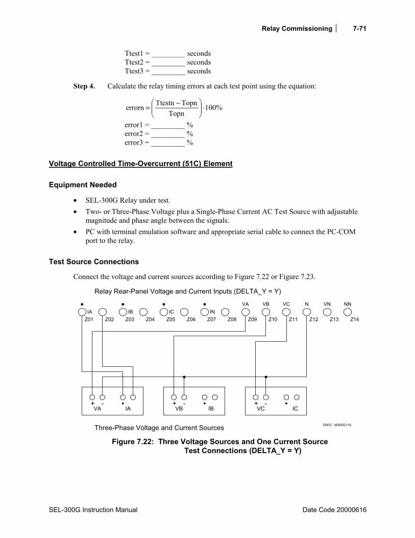
Relay Commissioning 7-71
SEL-300G Instruction Manual Date Code 20000616
Ttest1 = _________ seconds Ttest2 = _________ seconds Ttest3 = _________ seconds
Step 4. Calculate the relay timing errors at each test point using the equation:
%100Topn
TopnTtestnerrorn ⋅
−=
error1 = _________ % error2 = _________ % error3 = _________ %
Voltage Controlled Time-Overcurrent (51C) Element
Equipment Needed
• SEL-300G Relay under test. • Two- or Three-Phase Voltage plus a Single-Phase Current AC Test Source with adjustable
magnitude and phase angle between the signals. • PC with terminal emulation software and appropriate serial cable to connect the PC-COM
port to the relay.
Test Source Connections
Connect the voltage and current sources according to Figure 7.22 or Figure 7.23.
DWG: M300G116
+ -VA IA
+ -VB IB
+ -VC IC
Three-Phase Voltage and Current Sources
Z01IA
Z02 Z03 Z04 Z05 Z07 Z08 Z09 Z10 Z11 Z12IB IC IN
VA
Z13 Z14
VB VC N VN NN
Relay Rear-Panel Voltage and Current Inputs (DELTA_Y = Y)
Z06
Figure 7.22: Three Voltage Sources and One Current Source
Test Connections (DELTA_Y = Y)
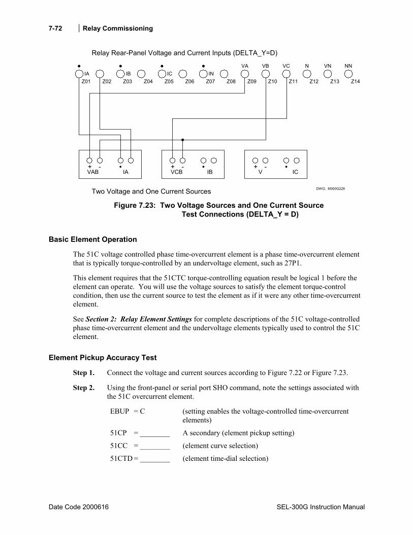
Relay Commissioning
Date Code 2000616 SEL-300G Instruction Manual
7-72
DWG: M300G228
+ -VAB IA
+ -VCB IB
+ -V IC
Two Voltage and One Current Sources
Z01IA
Z02 Z03 Z04 Z05 Z06 Z07 Z08 Z09 Z10 Z11 Z12IB IC IN
VA
Z13 Z14
VB VC N VN NN
Relay Rear-Panel Voltage and Current Inputs (DELTA_Y=D)
Figure 7.23: Two Voltage Sources and One Current Source
Test Connections (DELTA_Y = D)
Basic Element Operation
The 51C voltage controlled phase time-overcurrent element is a phase time-overcurrent element that is typically torque-controlled by an undervoltage element, such as 27P1.
This element requires that the 51CTC torque-controlling equation result be logical 1 before the element can operate. You will use the voltage sources to satisfy the element torque-control condition, then use the current source to test the element as if it were any other time-overcurrent element.
See Section 2: Relay Element Settings for complete descriptions of the 51C voltage-controlled phase time-overcurrent element and the undervoltage elements typically used to control the 51C element.
Element Pickup Accuracy Test
Step 1. Connect the voltage and current sources according to Figure 7.22 or Figure 7.23.
Step 2. Using the front-panel or serial port SHO command, note the settings associated with the 51C overcurrent element.
EBUP = C (setting enables the voltage-controlled time-overcurrent elements)
51CP = ________ A secondary (element pickup setting)
51CC = ________ (element curve selection)
51CTD = ________ (element time-dial selection)

Relay Commissioning 7-73
SEL-300G Instruction Manual Date Code 20000616
51CRS = _________ (electromechanical reset selection)
51CTC = 27PP1 ⋅ !60LOP Torque-Control Setting (element is enabled when 51CTC = logical 1; typical setting shown)
Using the front-panel or serial port SHO command, note the pickup setting for the torque controlling undervoltage element:
27PP1 = ________ volts
Using the front-panel or serial port SHO G command, note the global PHROT and DELTA_Y setting:
PHROT = _______ ABC or ACB (generator phase rotation) DELTA_Y = _______ Y or D (generator pt connection)
Step 3. Set the test source voltage magnitudes less than 27PP1. Set the test source voltage phase angles as shown in Figure 7.7.
The 51CP pickup setting is made directly in secondary amps, so the element will pick up when the applied current magnitude is equal to the pickup setting.
Iop = ________ A secondary
When performing this test manually, it is easy to determine when an instantaneous element picks up by viewing the element state directly using the front-panel TARGET function. Press the front-panel OTHER pushbutton, use the Down arrow button to underline the word TAR in the LCD display, then press SELECT. This command sequence causes the LCD display and lower deck of target LEDs to display individual Relay Word rows. Press the Down arrow button several times to display Relay Word Row 7, which contains the voltage controlled phase time-overcurrent element indications, as shown in Table 7.15.
Table 7.15: Relay Word Row 7 Shows Relay Word Bits for Voltage Controlled Time-Overcurrent Elements
Target • • • • • • • •
LED 24 27/59 32 40 46 64G 81 87
TAR 7 Command causes these LEDs to represent:
*
*
*
*
51CTC
51C
51CT
51CR
With voltage applied as described above, the relay should display the 51CTC and 51CR Relay Word bit names in the LCD display and illuminate the 46 and 87 LEDs, which the TAR command reassigns to display the 51CTC and 51CR Relay Word bit states, respectively, as shown in Table 7.15.
During the manual test, as you change the test current magnitude, you can see the 51C Relay Word bit asserts and deasserts to indicate pickup and dropout of the element.
Relay Commissioning
Date Code 2000616 SEL-300G Instruction Manual
7-74
If you prefer to monitor a contact closure to indicate element pickup, use the Access Level 2 SET command to program an output contact to close when the element under test picks up.
Step 4. Gradually increase the magnitude of the test current. Record the current magnitude applied to the relay when the instantaneous element under test asserts.
Itest = ________ A secondary
Use the equation below to calculate the element error:
%100Iop
IopItesterror ⋅
−=
error = _________ %
Element Timing Accuracy Test
Note: This procedure uses the setup from the Element Pickup Accuracy Test. Perform the Element Pickup Accuracy Test before proceeding with the Element Timing Accuracy Test.
The object of the Element Timing Accuracy Test is to apply predefined signals to the relay and measure the element response time. There are two methods available to measure the element response time, SER review and output contact operation. These methods are described in Test Methods on page 7-4.
Inverse-Time Accuracy Test
To test 51C overcurrent element inverse-time characteristic, this test procedure uses three test points to verify that the element is operating properly.
Step 1. Use the equations below to calculate the test current magnitudes for Test Point 1, Test Point 2, and Test Point 3.
CP5131Itest ⋅= A secondary Itest1 = ___________ A secondary
CP5152Itest ⋅= A secondary Itest2 = ___________ A secondary
CP5173Itest ⋅= A secondary Itest3 = ___________ A secondary
Calculate the expected operate time at each test point using the equation defined by the element settings (see Overcurrent Elements in Section 2: Relay Element Settings), and using M = 3, 5, and 7 as defined above.
Top1 = _____________ seconds Top2 = _____________ seconds Top3 = _____________ seconds
Relay Commissioning 7-75
SEL-300G Instruction Manual Date Code 20000616
Step 2. Based on the two timing test descriptions above (SER or output contact driving an external timer), select one method and make the settings and connections necessary to support the selection. Configure the current test source to apply single-phase current with magnitude equal to Itest1. Apply balanced voltages as in Step 3 of the element pickup accuracy test.
Step 3. Apply the test current and record the element operating time, Ttest1. Remove the test current for a few minutes to permit the element to fully reset if electromechanical reset is enabled (51CRS = Y). Repeat using Itest2 and Itest3.
Ttest1 = _________ seconds Ttest2 = _________ seconds Ttest3 = _________ seconds
Step 4. Calculate the relay timing errors at each test point using the equation:
%100Topn
TopnTtestnerrorn ⋅
−=
error1 = _________ % error2 = _________ % error3 = _________ %
Voltage Restrained Time-Overcurrent (51V) Element
Equipment Needed
• SEL-300G Relay under test. • Two- or Three-Phase Voltage plus a Single-Phase Current AC Test Source with adjustable
magnitude and phase angle between the signals. • PC with terminal emulation software and appropriate serial cable to connect the PC-COM
port to the relay.
Test Source Connections
Connect the voltage and current sources according to Figure 7.22 or Figure 7.23.
Basic Element Operation
The 51V voltage restrained phase time-overcurrent element is a phase time-overcurrent element whose pickup sensitivity depends on the magnitude of the applied phase voltage. The relationship between element pickup current and phase voltage is linear; that is, if the phase voltage magnitude is 50% of nominal, the actual 51V element pickup current is 50% of the set 51VP value.
See Section 2: Relay Element Settings for a complete description of the 51V voltage-restrained phase time-overcurrent element.

Relay Commissioning
Date Code 2000616 SEL-300G Instruction Manual
7-76
Element Pickup Accuracy Test
Step 1. Connect the voltage and current sources according to Figure 7.22 or Figure 7.23.
Step 2. Using the front-panel or serial port SHO command, note the settings associated with the 51V overcurrent element.
VNOM = _______ volts (generator nominal phase-to-phase voltage) EBUP = V (setting enables the voltage restrained time-overcurrent
elements) 51VP = ________ A secondary (element pickup setting) 51VC = ________ (element curve selection) 51VTD = ________ (element time-dial selection) 51VRS = _________ (electromechanical reset selection) 51VTC = !60LOP
Torque-Control Setting (element is enabled when 51VTC = logical 1; typical setting shown)
Using the front-panel or serial port SHO G command, note the global PHROT and DELTA_Y setting:
PHROT = _______ ABC or ACB (generator phase rotation) DELTA_Y = _______ Y or D (generator pt connection)
Step 3. Set the test source voltage magnitudes equal to VNOM/1.73 when DELTA_Y = Y or equal to VNOM when DELTA_Y = D. Set the test source voltage phase angles as shown in Figure 7.7 or Figure 7.8.
The 51VP pickup setting is made directly in secondary amps. However, the actual pickup is adjusted by the ratio of the applied voltage to the nominal voltage, as shown in the equation below. To verify the linear nature of the element voltage restraint characteristic, test the pickup at three different voltage levels.
VP511Iop = A secondary
732.1VNOM1Vop = V secondary (DELTA_Y = Y)
VNOM1Vop = V secondary (DELTA_Y = D)
Iop1 = ________ A secondary
Vop1 = _______ V secondary
75.0VP512Iop ⋅= A secondary
732.1VNOM75.02Vop ⋅= V secondary (DELTA_Y = Y)
VNOM75.02Vop ⋅= V secondary (DELTA_Y = D)
Iop2 = ________ A secondary

Relay Commissioning 7-77
SEL-300G Instruction Manual Date Code 20000616
Vop2 = _______ V secondary
5.0VP513Iop ⋅= A secondary
732.1VNOM5.03Vop ⋅= V secondary (DELTA_Y = Y)
VNOM5.03Vop ⋅= V secondary (DELTA_Y = D)
Iop3 = ________ A secondary
Vop3 = _______ V secondary
When performing this test manually, it is easy to determine when an instantaneous element picks up by viewing the element state directly using the front-panel TARGET function. Press the front-panel OTHER pushbutton, use the Down arrow button to underline the word TAR in the LCD display, then press SELECT. This command sequence causes the LCD display and lower deck of target LEDs to display individual Relay Word rows. Press the Down arrow button several times to display Relay Word Row 9, which contains the voltage restrained phase time-overcurrent element indications, as shown in Table 7.16.
Table 7.16: Relay Word Row 9 Shows Relay Word Bits for the Voltage Restrained Time-Overcurrent Elements
Target • • • • • • • •
LED 24 27/59 32 40 46 64G 81 87
TAR 9 Command causes these LEDs to represent:
51VTC
51V
51VT
51VR
PDEM
QDEM
GDEM
NDEM
With voltage applied as described above, the relay should display the 51VTC and 51VR Relay Word bit names in the LCD display, and illuminate the 24 and 40 LEDs, which the TAR command reassigns to display the 51VTC and 51VR Relay Word bit states, respectively, as shown in Table 7.16.
During the manual test, as you change the test current magnitude, you can see the 51V Relay Word bit asserts and deasserts to indicate pickup and dropout of the element.
If you prefer to monitor a contact closure to indicate element pickup, use the Access Level 2 SET command to program an output contact to close when the element under test picks up.
Step 4. Apply Vop1 to the phase voltage input corresponding to the phase where test current is applied. Apply VNOM/1.73 (DELTA_Y = Y) or VNOM (DELTA_Y = D) to the remaining phase(s). Gradually increase the magnitude of the test current. Record the current magnitude applied to the relay when the 51V element asserts.

Relay Commissioning
Date Code 2000616 SEL-300G Instruction Manual
7-78
Itest1 = ________ A secondary
Repeat for Vop2 and Vop3, keeping the remaining two voltage sources at VNOM/1.732 volts (DELTA_Y = Y) or VNOM (DELTA_Y = D).
Itest2 = ________ A secondary Itest3 = ________ A secondary
Use the equation below to calculate the element error:
%100Iopn
IopnItestnerrorn ⋅
−=
error1 = _________ % error2 = _________ % error3 = _________ %
Element Timing Accuracy Test
Note: This procedure uses the setup from the Element Pickup Accuracy Test. Perform the Element Pickup Accuracy Test before proceeding with the Element Timing Accuracy Test.
The object of the Element Timing Accuracy Test is to apply predefined signals to the relay and measure the element response time. There are two methods available to measure the element response time, SER review and output contact operation. These methods are described in Test Methods on page 7-4.
Inverse-Time Accuracy Test
To test 51V overcurrent element inverse-time characteristic, this test procedure uses three test points to verify that the element is operating properly.
Step 1. Use the equations below to calculate the test current magnitudes for Test Point 1, Test Point 2, and Test Point 3.
VP5131Itest ⋅= A secondary Itest1 = ___________ A secondary
VP5152Itest ⋅= A secondary Itest2 = ___________ A secondary
VP5173Itest ⋅= A secondary Itest3 = ___________ A secondary
Calculate the expected operate time at each test point using the equation defined by the element settings (see Overcurrent Elements in Section 2: Relay Element Settings), and using M = 3, 5, and 7, as defined above.
Top1 = _____________ seconds Top2 = _____________ seconds Top3 = _____________ seconds
Relay Commissioning 7-79
SEL-300G Instruction Manual Date Code 20000616
Step 2. Based on the two timing test descriptions above (SER or output contact driving an external timer), select one method and make the settings and connections necessary to support the selection. Configure the current test source to apply single-phase current with magnitude equal to Itest1. Apply balanced voltages as in Step 3 above, with phase voltage magnitudes set equal to VNOM/1.732 volts (DELTA_Y = Y) or VNOM (DELTA_Y = D).
Step 3. Apply the test current and record the element operating time, Ttest1. Remove the test current for a few minutes to permit the element to fully reset if electromechanical reset is enabled (51VRS = Y). Repeat using Itest2 and Itest3.
Ttest1 = _________ seconds Ttest2 = _________ seconds Ttest3 = _________ seconds
Step 4. Calculate the relay timing errors at each test point using the equation:
%100Topn
TopnTtestnerrorn ⋅
−=
error1 = _________ % error2 = _________ % error3 = _________ %
Step 5. To verify the element timing characteristic under reduced voltage conditions, select one or two reduced voltages to test under.
Vtest1 = ________ V secondary
Calculate new Itest quantities using the equations:
VP513VNOM
1Vtest732.11Itest ⋅⋅
⋅= A secondary (DELTA_Y = Y)
VP513VNOM
1Vtest1Itest ⋅⋅
= A secondary (DELTA_Y = D)
Itest1 = ___________ A secondary
VP515VNOM
1Vtest732.12Itest ⋅⋅
⋅= A secondary (DELTA_Y = Y)
VP515VNOM
1Vtest2Itest ⋅⋅
= A secondary (DELTA_Y = D)
Itest2 = ___________ A secondary
VP517VNOM
1Vtest732.13Itest ⋅⋅
⋅= A secondary (DELTA_Y = Y)
VP517VNOM
1Vtest3Itest ⋅⋅
= A secondary (DELTA_Y = D)

Relay Commissioning
Date Code 2000616 SEL-300G Instruction Manual
7-80
Itest3 = ___________ A secondary
Apply the test current to the same phase that Vtest1 is applied to. These test currents will result in the same expected operate times calculated in Step 1 above.
Overvoltage (59) Elements
Equipment Needed
• SEL-300G Relay under test. • Single-Phase AC Voltage Test Source with adjustable magnitude. • PC with terminal emulation software and appropriate serial cable to connect the PC-COM
port to the relay.
Test Source Connections
Connect the voltage source according to Figure 7.24 (DELTA_Y - Y) or Figure 7.25 (DELTA_Y = D).
DWG: M300G119
+ -VA IA
Single-Phase Voltage Sources
Z01IA
Z02 Z03 Z04 Z05 Z06 Z07 Z08 Z09 Z10 Z11 Z12IB IC IN
VA
Z13 Z14
VB VC N VN NN
Relay Rear-Panel Voltage and Current Inputs
Figure 7.24: One Voltage Source Test Connection (DELTA_Y = Y)
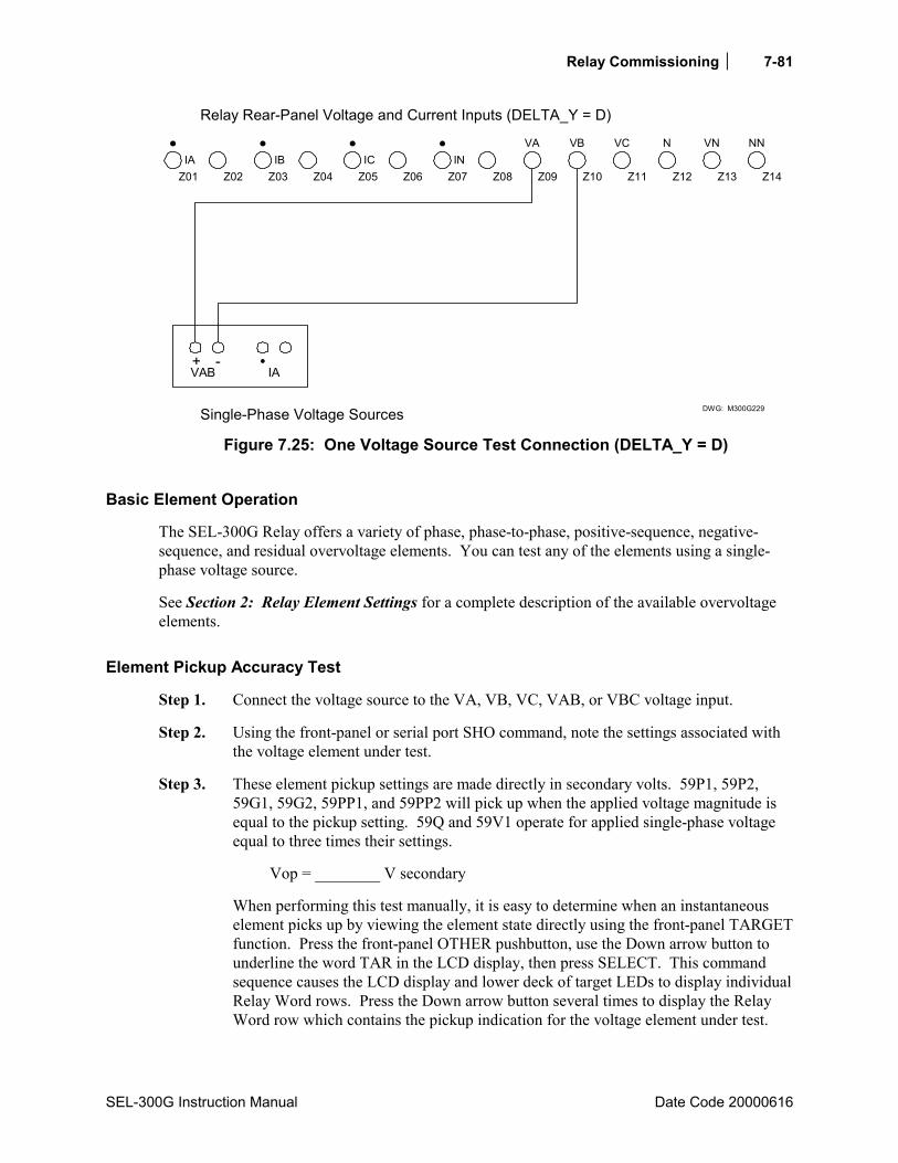
Relay Commissioning 7-81
SEL-300G Instruction Manual Date Code 20000616
DWG: M300G229
+ -VAB IA
Single-Phase Voltage Sources
Z01IA
Z02 Z03 Z04 Z05 Z06 Z07 Z08 Z09 Z10 Z11 Z12IB IC IN
VA
Z13 Z14
VB VC N VN NN
Relay Rear-Panel Voltage and Current Inputs (DELTA_Y = D)
Figure 7.25: One Voltage Source Test Connection (DELTA_Y = D)
Basic Element Operation
The SEL-300G Relay offers a variety of phase, phase-to-phase, positive-sequence, negative-sequence, and residual overvoltage elements. You can test any of the elements using a single-phase voltage source.
See Section 2: Relay Element Settings for a complete description of the available overvoltage elements.
Element Pickup Accuracy Test
Step 1. Connect the voltage source to the VA, VB, VC, VAB, or VBC voltage input.
Step 2. Using the front-panel or serial port SHO command, note the settings associated with the voltage element under test.
Step 3. These element pickup settings are made directly in secondary volts. 59P1, 59P2, 59G1, 59G2, 59PP1, and 59PP2 will pick up when the applied voltage magnitude is equal to the pickup setting. 59Q and 59V1 operate for applied single-phase voltage equal to three times their settings.
Vop = ________ V secondary
When performing this test manually, it is easy to determine when an instantaneous element picks up by viewing the element state directly using the front-panel TARGET function. Press the front-panel OTHER pushbutton, use the Down arrow button to underline the word TAR in the LCD display, then press SELECT. This command sequence causes the LCD display and lower deck of target LEDs to display individual Relay Word rows. Press the Down arrow button several times to display the Relay Word row which contains the pickup indication for the voltage element under test.

Relay Commissioning
Date Code 2000616 SEL-300G Instruction Manual
7-82
See TARGET Command in Section 10: Serial Port Communications and Commands for additional details.
During the manual test, as you change the test voltage magnitude, you can see Relay Word bits assert and deassert to indicate pickup and dropout of the respective elements.
If you prefer to monitor a contact closure to indicate element pickup, use the Access Level 2 SET command to program an output contact to close when the element under test picks up.
Step 4. Gradually increase the magnitude of the test voltage. Record the voltage magnitude applied to the relay when the overvoltage element under test picks up.
Vtest = ________ V secondary
Use the equation below to calculate the element error:
%100Vop
VopVtesterror ⋅
−=
error = _________ %
100% Stator Ground (64) Element
Equipment Needed
• SEL-300G Relay under test. • Single-Phase AC Voltage Test Source with adjustable magnitude for 64G1 element test. • Two Single-Phase AC Voltage Test Sources with adjustable magnitude and frequency for
64G2 element test (64RAT ≠ 0). • Four Single-Phase AC Voltage Test Sources with adjustable magnitude, phase angles, and
frequency for 64G2 element test (64RAT = 0). • PC with terminal emulation software and appropriate serial cable to connect the PC-COM
port to the relay.
Basic Element Operation
64G1 Element Operation
The 64G1 element is a fundamental frequency neutral overvoltage element with a definite-time delay.
64G2 Element Operation, 64RAT ≠ 0
In the standard application, the 64G2 element 64RAT setting is set to a nonzero value. In this case, the element acts as a third-harmonic voltage differential element. The relay measures the third-harmonic voltage at the phase voltage inputs and the neutral voltage input. The relay then multiplies the phase measurement third-harmonic magnitude by the 64RAT setting and takes the
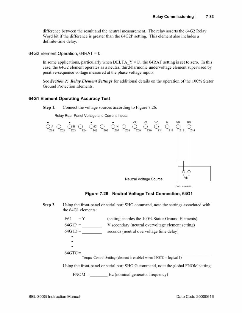
Relay Commissioning 7-83
SEL-300G Instruction Manual Date Code 20000616
difference between the result and the neutral measurement. The relay asserts the 64G2 Relay Word bit if the difference is greater than the 64G2P setting. This element also includes a definite-time delay.
64G2 Element Operation, 64RAT = 0
In some applications, particularly when DELTA_Y = D, the 64RAT setting is set to zero. In this case, the 64G2 element operates as a neutral third-harmonic undervoltage element supervised by positive-sequence voltage measured at the phase voltage inputs.
See Section 2: Relay Element Settings for additional details on the operation of the 100% Stator Ground Protection Elements.
64G1 Element Operating Accuracy Test
Step 1. Connect the voltage sources according to Figure 7.26.
DWG: M300G120
Neutral Voltage Source
Z01IA
Z02 Z03 Z04 Z05 Z06 Z07 Z08 Z09 Z10 Z11 Z12IB IC IN
VA
Z13 Z14
VB VC N VN NN
Relay Rear-Panel Voltage and Current Inputs
+ -VN
Figure 7.26: Neutral Voltage Test Connection, 64G1
Step 2. Using the front-panel or serial port SHO command, note the settings associated with the 64G1 elements:
E64 = Y (setting enables the 100% Stator Ground Elements) 64G1P = _________ V secondary (neutral overvoltage element setting) 64G1D = _________ seconds (neutral overvoltage time delay) 64GTC = ___________________________________________________________
Torque-Control Setting (element is enabled when 64GTC = logical 1)
Using the front-panel or serial port SHO G command, note the global FNOM setting:
FNOM = ________ Hz (nominal generator frequency)
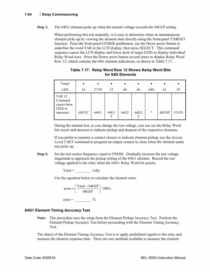
Relay Commissioning
Date Code 2000616 SEL-300G Instruction Manual
7-84
Step 3. The 64G1 element picks up when the neutral voltage exceeds the 64G1P setting.
When performing this test manually, it is easy to determine when an instantaneous element picks up by viewing the element state directly using the front-panel TARGET function. Press the front-panel OTHER pushbutton, use the Down arrow button to underline the word TAR in the LCD display, then press SELECT. This command sequence causes the LCD display and lower deck of target LEDs to display individual Relay Word rows. Press the Down arrow button several times to display Relay Word Row 12, which contains the 64G element indications, as shown in Table 7.17.
Table 7.17: Relay Word Row 12 Shows Relay Word Bits for 64G Elements
Target • • • • • • • •
LED 24 27/59 32 40 46 64G 81 87
TAR 12 Command causes these LEDs to represent:
64GTC
64G1
64G1T
64G2
64G2T
*
60LOP
CLEN
During the manual test, as you change the test voltage, you can see the Relay Word bits assert and deassert to indicate pickup and dropout of the respective elements.
If you prefer to monitor a contact closure to indicate element pickup, use the Access Level 2 SET command to program an output contact to close when the element under test picks up.
Step 4. Set the test source frequency equal to FNOM. Gradually increase the test voltage magnitude to approach the pickup setting of the 64G1 element. Record the test voltage applied to the relay when the 64G1 Relay Word bit asserts.
Vtest = ________ volts
Use the equation below to calculate the element error:
%100P1G64
P1G64Vtesterror ⋅
−=
error = _________ %
64G1 Element Timing Accuracy Test
Note: This procedure uses the setup from the Element Pickup Accuracy Test. Perform the Element Pickup Accuracy Test before proceeding with the Element Timing Accuracy Test.
The object of the Element Timing Accuracy Test is to apply predefined signals to the relay and measure the element response time. There are two methods available to measure the element
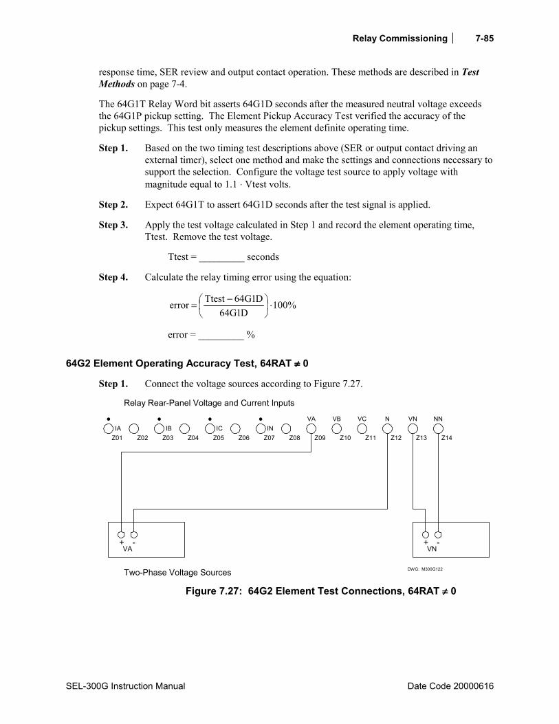
Relay Commissioning 7-85
SEL-300G Instruction Manual Date Code 20000616
response time, SER review and output contact operation. These methods are described in Test Methods on page 7-4.
The 64G1T Relay Word bit asserts 64G1D seconds after the measured neutral voltage exceeds the 64G1P pickup setting. The Element Pickup Accuracy Test verified the accuracy of the pickup settings. This test only measures the element definite operating time.
Step 1. Based on the two timing test descriptions above (SER or output contact driving an external timer), select one method and make the settings and connections necessary to support the selection. Configure the voltage test source to apply voltage with magnitude equal to 1.1 ⋅ Vtest volts.
Step 2. Expect 64G1T to assert 64G1D seconds after the test signal is applied.
Step 3. Apply the test voltage calculated in Step 1 and record the element operating time, Ttest. Remove the test voltage.
Ttest = _________ seconds
Step 4. Calculate the relay timing error using the equation:
%100D1G64
D1G64Ttesterror ⋅
−=
error = _________ %
64G2 Element Operating Accuracy Test, 64RAT ≠≠≠≠ 0
Step 1. Connect the voltage sources according to Figure 7.27.
DWG: M300G122
+ -VA
Two-Phase Voltage Sources
Z01IA
Z02 Z03 Z04 Z05 Z06 Z07 Z08 Z09 Z10 Z11 Z12IB IC IN
VA
Z13 Z14
VB VC N VN NN
Relay Rear-Panel Voltage and Current Inputs
+ -VN
Figure 7.27: 64G2 Element Test Connections, 64RAT ≠≠≠≠ 0

Relay Commissioning
Date Code 2000616 SEL-300G Instruction Manual
7-86
Step 2. Using the front-panel or serial port SHO command, note the settings associated with the 64G2 elements:
E64 = Y (setting enables the 100% Stator Ground Elements)
64G2P = ________ V secondary (third-harmonic voltage differential element setting)
64RAT = ________ (third-harmonic voltage ratio setting) 64G2D = ________ seconds (third-harmonic voltage differential time delay) 64GTC = ___________________________________________________________
Torque-Control Setting (element is enabled when 64GTC = logical 1)
Using the front-panel or serial port SHO G command, note the global FNOM setting:
FNOM = ________ Hz (nominal generator frequency)
Step 3. The 64G2 element picks up when the third-harmonic voltage difference, VDIFF, exceeds the 64G2P setting, as defined by the following equation:
3VN3VPRAT64Vdiff −⋅=
Set the frequency of both voltage sources equal to 3⋅FNOM. Set the magnitude of the test source connected to the VN input equal to 5 volts. Set the magnitude of the test source connected to the phase voltage input equal to 5/64RAT.
Calculate the expected element operate voltage using the equation:
P2G645RAT64Vop ±⋅= Vop = ________ V secondary
When performing this test manually, it is easy to determine when an instantaneous element picks up by viewing the element state directly using the front-panel TARGET function. Press the front-panel OTHER pushbutton, use the Down arrow button to underline the word TAR in the LCD display, then press SELECT. This command sequence causes the LCD display and lower deck of target LEDs to display individual Relay Word rows. Press the Down arrow button several times to display Relay Word Row 12, which contains the 64G element indications, as shown in Table 7.17.
During the manual test, as you change the test voltage, you can see the Relay Word bits assert and deassert to indicate pickup and dropout of the respective elements.
If you prefer to monitor a contact closure to indicate element pickup, use the Access Level 2 SET command to program an output contact to close when the element under test picks up.
Step 4. Gradually decrease the neutral voltage magnitude. Record the test voltage applied to the relay when the 64G2 Relay Word bit asserts.
Vtest = ________ volts

Relay Commissioning 7-87
SEL-300G Instruction Manual Date Code 20000616
Use the equation below to calculate the element error:
( ) %100P2G64
P2G64Vtest5RAT64error ⋅
−−⋅=
error = _________ %
64G2 Element Timing Accuracy Test, 64RAT ≠≠≠≠ 0
Note: This procedure uses the setup from the Element Pickup Accuracy Test. Perform the Element Pickup Accuracy Test before proceeding with the Element Timing Accuracy Test.
The object of the Element Timing Accuracy Test is to apply predefined signals to the relay and measure the element response time. There are two methods available to measure the element response time, SER review and output contact operation. These methods are described in Test Methods beginning on page 7-4.
The 64G2T Relay Word bit asserts 64G2D seconds after the measured third-harmonic differential voltage exceeds the 64G2P pickup setting. The Element Pickup Accuracy Test verified the accuracy of the pickup settings. This test measures the element definite operating time.
Step 1. Based on the two timing test descriptions above (SER or output contact driving an external timer), select one method and make the settings and connections necessary to support the selection. Configure the voltage test sources to apply neutral and phase voltages with magnitudes as calculated in Step 3 above. Configure the neutral voltage test source to switch from 5 volts to a voltage magnitude equal to 0.9 ⋅ Vtest volts, as determined in Step 4, above.
Step 2. Expect 64G2T to assert 64G2D seconds after the test signal is applied.
Step 3. Apply the test voltage calculated in Step 1 and record the element operating time, Ttest. Remove the test voltages.
Ttest = _________ seconds
Step 4. Calculate the relay timing error using the equation:
%100D2G64
D2G64Ttesterror ⋅
−=
error = _________ %
64G2 Element Operating Accuracy Test, 64RAT = 0
Step 1. Connect the voltage sources according to Figure 7.28.

Relay Commissioning
Date Code 2000616 SEL-300G Instruction Manual
7-88
DWG: M300G121
+ -VAB
+ -VBC
Two-Phase Voltage and Neutral Voltage Sources
Z01IA
Z02 Z03 Z04 Z05 Z06 Z07 Z08 Z09 Z10 Z11 Z12IB IC IN
VA
Z13 Z14
VB VC N VN NN
Relay Rear-Panel Voltage and Current Inputs
+ -VN
Figure 7.28: 64G2 Element Test Connections, 64RAT = 0
(DELTA_Y = D)
Step 2. Using the front-panel or serial port SHO command, note the settings associated with the 64G2 elements:
VNOM = ________ volts (nominal generator phase-to-phase voltage) E64 = Y (setting enables the 100% Stator Ground Elements) 64G2P = ________ V secondary (third-harmonic voltage differential element
setting) 64RAT = 0 (third-harmonic voltage ratio setting) 64G2D = ________ seconds (third-harmonic voltage differential time delay) 64GTC = __________________________________________________________
Torque-Control Setting (element is enabled when 64GTC = logical 1)
Using the front-panel or serial port SHO G command, note the global FNOM, PHROT, and DELTA_Y settings:
FNOM = ________ Hz (nominal generator frequency) PHROT = ________ ABC or ACB (generator phase rotation) DELTA_Y = ________ Y or D (generator pt connections)
Step 3. The 64G2 element picks up when the neutral third-harmonic voltage falls below the 64G2P setting.
Set the frequency of the phase voltage sources equal to FNOM. Set the magnitudes of the phase voltage sources equal to VNOM. Set the phase test source phase angles as shown in Figure 7.7 or Figure 7.8, DELTA_Y = D.
Set the neutral voltage test source frequency equal to 3⋅FNOM. Set the magnitude of the test source connected to the VN input greater than the 64G2P setting.
Calculate the expected element operate voltage using the equation:
Relay Commissioning 7-89
SEL-300G Instruction Manual Date Code 20000616
P2G64Vop = Vop = ________ V secondary
When performing this test manually, it is easy to determine when an instantaneous element picks up by viewing the element state directly using the front-panel TARGET function. Press the front-panel OTHER pushbutton, use the Down arrow button to underline the word TAR in the LCD display, then press SELECT. This command sequence causes the LCD display and lower deck of target LEDs to display individual Relay Word rows. Press the Down arrow button several times to display Relay Word Row 12, which contains the 64G element indications, as shown in Table 7.17.
During the manual test, as you change the test voltage, you can see the Relay Word bits assert and deassert to indicate pickup and dropout of the respective elements.
If you prefer to monitor a contact closure to indicate element pickup, use the Access Level 2 SET command to program an output contact to close when the element under test picks up.
Step 4. Gradually decrease the neutral voltage magnitude. Record the test voltage applied to the relay when the 64G2 Relay Word bit asserts.
Vtest = ________ volts
Use the equation below to calculate the element error:
%100P2G64
P2G64Vtesterror ⋅
−=
error = _________ %
64G2 Element Timing Accuracy Test, 64RAT = 0
Note: This procedure uses the setup from the Element Pickup Accuracy Test. Perform the Element Pickup Accuracy Test before proceeding with the Element Timing Accuracy Test.
The object of the Element Timing Accuracy Test is to apply predefined signals to the relay and measure the element response time. There are two methods available to measure the element response time, SER review and output contact operation. These methods are described in Test Methods beginning on page 7-4.
The 64G2T Relay Word bit asserts 64G2D seconds after the measured neutral third-harmonic voltage falls below the 64G2P pickup setting. The Element Pickup Accuracy Test verified the accuracy of the pickup settings. This test measures the element definite operating time.
Step 1. Based on the two timing test descriptions above (SER or output contact driving an external timer), select one method and make the settings and connections necessary to support the selection. Configure the voltage test sources to apply neutral and phase voltages with magnitudes as calculated in Step 3 above. Configure the neutral voltage test source to switch from the original magnitude to a voltage magnitude equal to 0.9⋅ Vtest volts, as determined in Step 4, above.

Relay Commissioning
Date Code 2000616 SEL-300G Instruction Manual
7-90
Step 2. Expect 64G2T to assert 64G2D seconds after the test signal is applied.
Step 3. Apply the test voltage calculated in Step 1 and record the element operating time, Ttest. Remove the test voltages.
Ttest = _________ seconds
Step 4. Calculate the relay timing error using the equation:
%100D2G64
D2G64Ttesterror ⋅
−=
error = _________ %
Out-of-Step (78) ElementSingle Blinder
Equipment Needed
• SEL-300G Relay under test.
• Two- or Three-Phase AC Voltage and Current Test Source, with adjustable magnitude.
• PC with terminal emulation software and appropriate serial cable to connect the PC-COM port to the relay.
Test Source Connections
When DELTA_Y = Y, connect the voltage and current sources according to Figure 7.9. When DELTA_Y = D, connect the voltage and current sources according to Figure 7.10.
Basic Element Operation
The single blinder scheme, shown in Figure 7.29, consists of mho element 78Z1, right blinder 78R1, and left blinder 78R2. This scheme detects an out-of-step condition by tracking the path of positive-sequence impedance trajectories that pass through the protection zone. If the relay detects an out-of-step condition, it asserts the following Relay Word bits:
Relay Word bit SWING picks up when the positive-sequence impedance moves from the load region into Area A (left blinder 78R2 and mho element 78Z1 assert).
Relay Word bit OOS picks up when the impedance trajectory advances further to Area B between the two blinders (right blinder 78R1, left blinder 78R2, and mho element 78Z1 assert).
At the time the impedance trajectory exits the mho circle via Area C, the rising-edge triggered timer with 78TD pickup delay and 78TDURD dropout-delay starts timing. Relay Word bit OOST remains picked up for 78TDURD seconds after the pickup delay time 78TD expires.
The above description is only for trajectories traveling from right to left. Out-of-step trajectories traveling from left to right traverse the protection zone in the reverse sequence

Relay Commissioning 7-91
SEL-300G Instruction Manual Date Code 20000616
(i.e., from Area C to B to A). The Relay Word bits assert in the same way whether trajectories travel from right to left or from left to right.
See Section 2: Relay Element Settings for a complete element description.
78Z1 Element Operating Accuracy Test
Step 1. Make test source connections according to Figure 7.9 or Figure 7.10.
Step 2. Using the front-panel or serial port SHO command, note the settings associated with the out-of-step elements:
VNOM = ________ volts (nominal phase-to-phase voltage) E78 = 1B (setting enables the out-of-step elements) 78FWD = ________ Ω secondary (forward reach setting)
78REV = _________ Ω secondary (reverse reach setting))
78R1 = _________ Ω secondary (right blinder setting)
78R2 = _________ Ω secondary (left blinder setting)
Using the front-panel or serial port SHO G command, note the global PHROT and DELTA_Y setting:
PHROT = _________ ABC or ACB (generator phase rotation)
DELTA_Y = _________ Y or D (generator PT connection)
Step 3. This element is easiest to test by changing the test current while holding test voltage equal to VNOM. Set the test source voltage magnitudes equal to VNOM/1.732 (DELTA_Y) or VNOM (DELTA_Y = D). Set the test source voltage phase angles as shown in Figure 7.7 or Figure 7.8.
Set the test source current phase angles as follows:
When setting PHROT = ABC, set angle Ia = 90° set angle Ib = -30° set angle Ic = -150°
When setting PHROT = ACB, set angle Ia = 90° set angle Ib = -150° set angle Ic = -30°

Relay Commissioning
Date Code 2000616 SEL-300G Instruction Manual
7-92
B
X
R
78REV
78FWD
78Z1
78R2Left Blinder
DWG: M300G245
78R2 78R1
78R1Right Blinder
AC
78R2Pickup
78R1Pickup
Figure 7.29: Out-of-Step Single Blinder Element, Diameter and Blinder Tests
Refer to Figure 7.29. With these current angle settings, 78Z1 element picks up if the ratio of voltage to current is less than or equal to the forward reach 78FWD (ohms) of the mho circle.
Expected value:
Iop78Z1 = setting 78FWD
Va (DELTA_Y = Y)
Iop78Z1 = setting 78FWD3
Va⋅
(DELTA_Y = D)
Expected Iop78Z1 = ______________ A secondary
Step 4. Turn on the current test sources and gradually increase the magnitude of all three phase currents. Record the applied current magnitude when the 78Z1 element asserts.
Itest78Z1 = ____________________ A secondary
Step 5. Use the equations below to calculate the element error:
error78Z1 = %100settingFWD78
settingFWD781Z78Itest
Va
⋅
− (DELTA_Y = Y)
Relay Commissioning 7-93
SEL-300G Instruction Manual Date Code 20020206
error78Z1 = ( ) %100settingFWD78
settingFWD7831Z78Itest
Va
⋅
−⋅ (DELTA_Y = D)
error78Z1 = ___________________%
78R1 Element (Right Blinder) Operating Accuracy Test
Step 1. Make test source connections according to Figure 7.9 or Figure 7.10.
Step 2. Using the front-panel or serial port SHO command note the settings associated with the out-of-step single blinder element. Using the front-panel or serial port SHO G command note the global PHROT and DELTA_Y setting.
PHROT = _________ ABC or ACB (generator phase rotation)
DELTA_Y = _________ Y or D (generator PT connection)
Step 3. This element is easiest to test by changing the test current while holding the test voltage equal to VNOM. Set the test source voltage magnitude equal to VNOM\1.732 (DELTA_Y = Y) or VNOM (DELTA_Y = D).
Set the test source voltage phase angles as shown in Figure 7.7 or Figure 7.8.
Set the test source current phase angles as follows:
When setting PHROT = ABC, set angle Ia = 0° set angle Ib = 120° set angle Ic = 120°
When setting PHROT = ACB, set angle Ia = 0° set angle Ib = 120° set angle Ic = 120°
Refer to Figure 7.29. In this figure 78R1 element will pick up if the ratio of voltage and current applied is equal to or less than the ohmic value of 78R1.
Expected value:
Iop78R1 = ohms1R78
Va (DELTA_Y = Y)
Iop78R1 = ohms1R783
Va⋅
(DELTA_Y = D)
Expected Iop78R1 = _________ A secondary
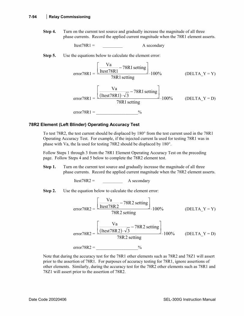
Relay Commissioning
Date Code 20020406 SEL-300G Instruction Manual
7-94
Step 4. Turn on the current test source and gradually increase the magnitude of all three phase currents. Record the applied current magnitude when the 78R1 element asserts.
Itest78R1 = _________ A secondary
Step 5. Use the equations below to calculate the element error:
error78R1 = %100setting1R78
setting1R781R78Itest
Va
⋅
− (DELTA_Y = Y)
error78R1 = ( ) %100setting1R78
setting1R7831R78Itest
Va
⋅
−⋅ (DELTA_Y = D)
error78R1 = ___________________%
78R2 Element (Left Blinder) Operating Accuracy Test
To test 78R2, the test current should be displaced by 180° from the test current used in the 78R1 Operating Accuracy Test. For example, if the injected current Ia used for testing 78R1 was in phase with Va, the Ia used for testing 78R2 should be displaced by 180°.
Follow Steps 1 through 3 from the 78R1 Element Operating Accuracy Test on the preceding page. Follow Steps 4 and 5 below to complete the 78R2 element test.
Step 1. Turn on the current test source and gradually increase the magnitude of all three phase currents. Record the applied current magnitude when the 78R2 element asserts.
Itest78R2 = _________ A secondary
Step 2. Use the equation below to calculate the element error:
error78R2 = %100setting2R78
setting2R782R78Itest
Va
⋅
− (DELTA_Y = Y)
error78R2 = ( ) %100setting2R78
setting2R7832R78Itest
Va
⋅
−⋅ (DELTA_Y = D)
error78R2 = ___________________%
Note that during the accuracy test for the 78R1 other elements such as 78R2 and 78Z1 will assert prior to the assertion of 78R1. For purposes of accuracy testing for 78R1, ignore assertions of other elements. Similarly, during the accuracy test for the 78R2 other elements such as 78R1 and 78Z1 will assert prior to the assertion of 78R2.
Relay Commissioning 7-95
SEL-300G Instruction Manual Date Code 20000616
Out-of-Step (78) ElementDouble Blinder
Equipment Needed
• SEL-300G Relay under test.
• Two- or Three-Phase AC Voltage and Current Test Source, with adjustable magnitude.
• PC with terminal emulation software and appropriate serial cable to connect the PC-COM port to the relay.
Test Source Connections
When DELTA_Y = Y, connect the voltage and current sources according to Figure 7.9. When DELTA_Y = D, connect the voltage and current sources according to Figure 7.10.
Basic Element Operation
The double blinder scheme, shown in Figure 7.30, consists of mho element 78Z1 and two blinder pairs: outer resistance blinder 78R1 and inner resistance blinder 78R2. This scheme uses timer 78D as part of its logic to detect out-of-step conditions. The scheme declares an out-of-step condition if the positive-sequence impedance stays between the two blinders for more than 78D seconds and advances further inside the inner blinder. The logic issues an out-of-step trip once an out-of-step condition is established and the positive-sequence impedance exits the mho circle.
If the relay detects an out-of-step condition, it asserts the following Relay Word bits:
Relay Word bit SWING picks up when the positive-sequence impedance stays between the outer and inner blinders for more than 78D seconds (78R1 asserts, mho element 78Z1 may or may not assert).
Relay Word bit OOS picks up when the impedance trajectory advances further inside the inner blinder (78R1, 78R2, and mho element 78Z1 assert).
At the time the impedance trajectory exits the mho circle, the rising-edge triggered timer with 78TD pickup delay and 78TDURD dropout delay starts timing. Relay Word bit OOST remains picked up for 78TDURD seconds after pickup delay time 78TD expires.
See Section 2: Relay Element Settings for a complete element description.
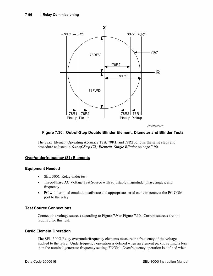
Relay Commissioning
Date Code 2000616 SEL-300G Instruction Manual
7-96
78R178R2 78R2
X
R
78Z1
78R1
DWG: M300G246
78REV
78FWD
78R2
78R1
78R1Pickup
78R2Pickup
78R2Pickup
78R1Pickup
Figure 7.30: Out-of-Step Double Blinder Element, Diameter and Blinder Tests
The 78Z1 Element Operating Accuracy Test, 78R1, and 78R2 follows the same steps and procedure as listed in Out-of-Step (78) ElementSingle Blinder on page 7-90.
Over/underfrequency (81) Elements
Equipment Needed
• SEL-300G Relay under test. • Three-Phase AC Voltage Test Source with adjustable magnitude, phase angles, and
frequency. • PC with terminal emulation software and appropriate serial cable to connect the PC-COM
port to the relay.
Test Source Connections
Connect the voltage sources according to Figure 7.9 or Figure 7.10. Current sources are not required for this test.
Basic Element Operation
The SEL-300G Relay over/underfrequency elements measure the frequency of the voltage applied to the relay. Underfrequency operation is defined when an element pickup setting is less than the nominal generator frequency setting, FNOM. Overfrequency operation is defined when
Relay Commissioning 7-97
SEL-300G Instruction Manual Date Code 20000616
the pickup setting is greater than FNOM. Frequency element operation is blocked when any phase voltage is less than the 27B81P undervoltage element setting.
Element Pickup Accuracy Test
Step 1. Connect the voltage sources according to Figure 7.9 or Figure 7.10. Current sources are not required for this test.
Step 2. Using the front-panel or serial port SHO command, note the settings associated with the frequency elements:
VNOM = ________ volts (nominal phase-to-phase voltage) E81 = 1-6 (setting enables a number of frequency elements) 27B81P = ________ V secondary (undervoltage element setting)
81D1P = _________ hertz (Level 1 pickup frequency)
81D1D = _________ seconds (Level 1 time delay)
81D2P = _________ hertz (Level 1 pickup frequency)
81D2D = _________ seconds (Level 1 time delay)
81D3P = _________ hertz (Level 1 pickup frequency)
81D3D = _________ seconds (Level 1 time delay)
81D4P = _________ hertz (Level 1 pickup frequency)
81D4D = _________ seconds (Level 1 time delay)
81D5P = _________ hertz (Level 1 pickup frequency)
81D5D = _________ seconds (Level 1 time delay)
81D6P = _________ hertz (Level 1 pickup frequency)
81D6D = _________ seconds (Level 1 time delay)
Using the front-panel or serial port SHO G command, note the global FNOM, PHROT, and DELTA_Y settings:
FNOM = ________ Hz (nominal generator frequency) PHROT = ________ ABC or ACB (generator phase rotation) DELTA_Y = ________ Y or D (generator pt connection)
Set the test source voltage magnitudes equal to VNOM/1.732 (DELTA_Y = Y) or VNOM (DELTA_Y = D). Set the test source voltage phase angles as shown in Figure 7.7 or Figure 7.8.
Step 3. To predict the test frequency where each element will operate, simply note the 81DnP pickup setting.
When performing this test manually, it is easy to determine when an instantaneous element picks up by viewing the element state directly using the front-panel TARGET function. Press the front-panel OTHER pushbutton, use the Down arrow button to underline the word TAR in the LCD display, then press SELECT. This command

Relay Commissioning
Date Code 2000616 SEL-300G Instruction Manual
7-98
sequence causes the LCD display and lower deck of target LEDs to display individual Relay Word rows. Press the Down arrow button several times to display Relay Word Row 14, which contains the frequency element indications, as shown in Table 7.18.
Table 7.18: Relay Word Row 14 Shows Relay Word Bits for Frequency Elements
Target • • • • • • • •
LED 24 27/59 32 40 46 64G 81 87
TAR 14 Command causes these LEDs to represent:
81D1
81D2
81D3
81D4
81D5
81D6
3PO
52A
During the manual test, as you change the test frequency, you can see the Relay Word bits assert and deassert to indicate pickup and dropout of the respective elements.
If you prefer to monitor a contact closure to indicate element pickup, use the Access Level 2 SET command to program an output contact to close when the element under test picks up.
Step 4. Gradually change the voltage source frequency to approach the pickup setting of the element under test. Record the test frequency applied to the relay when the instantaneous element under test asserts.
Ftest = ________ hertz
Use the equation below to calculate the element error:
DnP81Ftesterror −= error = _________ hertz
Element Timing Accuracy Test
Note: This procedure uses the setup from the Element Pickup Accuracy Test. Perform the Element Pickup Accuracy Test before proceeding with the Element Timing Accuracy Test.
The object of the Element Timing Accuracy Test is to apply predefined signals to the relay and measure the element response time. There are two methods available to measure the element response time, SER review and output contact operation. These methods are described in Test Methods beginning on page 7-4.
81DnD Time-Delay Accuracy Test
The 81DnT Relay Word bit asserts 81DnD seconds after the measured frequency falls below the element underfrequency setting or climbs above the element overfrequency setting. The Element Pickup Accuracy Test verified the accuracy of the pickup settings. This test measures the element definite operating time.

Relay Commissioning 7-99
SEL-300G Instruction Manual Date Code 20000616
Step 1. Based on the two timing test descriptions above (SER or output contact driving an external timer), select one method and make the settings and connections necessary to support the selection. Configure the voltage test sources to apply phase voltage with magnitude equal to VNOM/1.732 volts (DELTA_Y = Y) or VNOM volts (DELTA_Y = D) and frequency equal to:
1.1 ⋅ Ftest for an overfrequency element under test
or
0.9 ⋅ Ftest for an underfrequency element under test
Step 2. Expect 81DnT to assert 81DnD seconds after the test signals are applied.
Step 3. Apply the test voltages calculated in Step 1 and record the element operating time, Ttest. Remove the test voltages.
Ttest = _________ seconds
Step 4. Calculate the relay timing error using the equation:
%100DnD81
DnD81Ttesterror ⋅
−=
error = _________ %
Ground Differential (87N) Element
Equipment Needed
• SEL-300G Relay under test. • Two AC Current Test Sources with adjustable magnitude. • PC with terminal emulation software and appropriate serial cable to connect the PC-COM
port to the relay.
Test Source Connections
Connect the current sources according to Figure 7.31.

Relay Commissioning
Date Code 2000616 SEL-300G Instruction Manual
7-100
DWG: M300G226IA IN
Z01IA
Z02 Z03 Z04 Z05 Z07 Z08 Z09 Z10 Z11 Z12IB IC IN
VA
Z13 Z14
VB VC N VN NN
Relay Rear-Panel Voltage and Current Inputs
Z06
Figure 7.31: 87N Test Connections
Basic Element Operation
The SEL-300G Relay ground differential element detects generator ground faults on solidly or low-impedance grounded generators by calculating the difference between the neutral current and the residual current. When a generator ground fault occurs between the phase current transformers and the neutral current transformer, the difference current will be nonzero. When an external ground fault occurs, the difference current is zero. Thus, the relay does not trip for external ground faults, but can sensitively detect most internal ground faults. The relay ground differential element picks up when I87N, the ground difference current, is greater than the 87N element pickup setting. The relay calculates I87N using the equation:
INCTRN
CTRIGN87I −⋅= A secondary
Where:
I87N = Ground difference current IG = Measured residual current (IA + IB + IC) IN = Measured neutral current CTR = Phase CT Ratio CTRN = Neutral CT Ratio
The 87N1T and 87N2T are definite-time ground differential elements. If measured difference current exceeds the 87N1P setting, the relay asserts the 87N1P Relay Word bit to logical 1. If this condition continues for 87N1D seconds, the relay asserts the 87N11T Relay Word bit to logical 1. After the excessive current condition vanishes, the relay deasserts both Relay Word bits to logical 0. The 87N2P and 87N2T Relay Word bits operate similarly (see Section 13: Differential Element Settings for a complete description of the element).
Relay Commissioning 7-101
SEL-300G Instruction Manual Date Code 20000616
Element Pickup Accuracy Test
Step 1. Make test source connections according to Figure 7.31. Voltage sources are not required for this test and may be left disconnected.
Step 2. Using the front-panel or serial port SHO command, note the settings associated with the relay volts/hertz element:
CTR = ________ phase current transformer ratio to 1
CTRN = ________ neutral current transformer ratio to 1
E87N = Y (setting enables the ground differential elements)
87N1P = ________ amps secondary (element pickup setting)
87N1D = ________ seconds (element definite-time delay)
87N2P = ________ amps secondary (element pickup setting)
87N2D = ________ seconds (element definite-time delay)
87NTC = ____________________________________________________ Torque-Control Setting (elements are enabled when 87NTC = logical 1)
Step 3. This element is easiest to test by increasing neutral current until the element picks up. To prove differential operation, you can then increase the phase current while holding the neutral current constant until the element drops out.
To predict the test neutral current magnitude where the element will operate, use equation:
NnP87INop = A secondary
This calculation assumes that applied phase current is zero.
When performing this test manually, it is easy to determine when an instantaneous element picks up by viewing the element state directly using the front-panel TARGET function. Press the front-panel OTHER pushbutton, use the Down arrow button to underline the word TAR in the LCD display, then press SELECT. This command sequence causes the LCD display and lower deck of target LEDs to display individual Relay Word rows. Press the Down arrow button twice to display Relay Word Row 38, which contains the volts/hertz ground differential element indications as shown in Table 7.19.
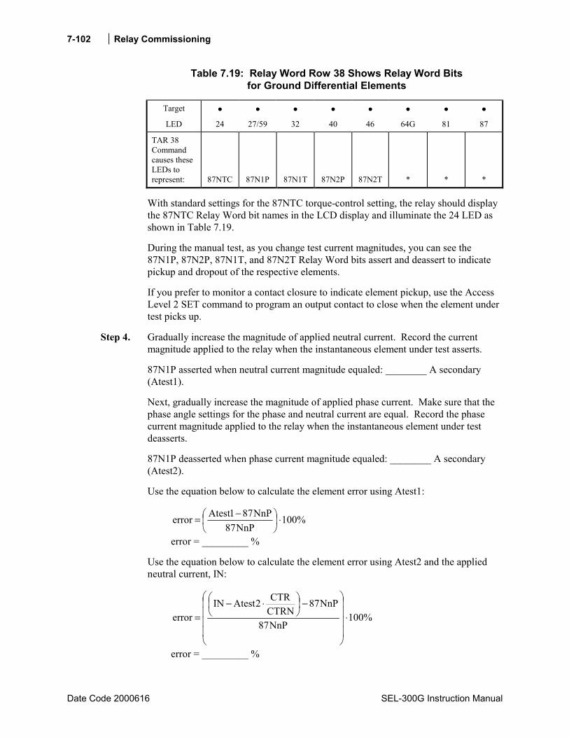
Relay Commissioning
Date Code 2000616 SEL-300G Instruction Manual
7-102
Table 7.19: Relay Word Row 38 Shows Relay Word Bits for Ground Differential Elements
Target •••• •••• •••• •••• •••• •••• •••• ••••
LED 24 27/59 32 40 46 64G 81 87
TAR 38 Command causes these LEDs to represent:
87NTC
87N1P
87N1T
87N2P
87N2T
*
*
*
With standard settings for the 87NTC torque-control setting, the relay should display the 87NTC Relay Word bit names in the LCD display and illuminate the 24 LED as shown in Table 7.19.
During the manual test, as you change test current magnitudes, you can see the 87N1P, 87N2P, 87N1T, and 87N2T Relay Word bits assert and deassert to indicate pickup and dropout of the respective elements.
If you prefer to monitor a contact closure to indicate element pickup, use the Access Level 2 SET command to program an output contact to close when the element under test picks up.
Step 4. Gradually increase the magnitude of applied neutral current. Record the current magnitude applied to the relay when the instantaneous element under test asserts.
87N1P asserted when neutral current magnitude equaled: ________ A secondary (Atest1).
Next, gradually increase the magnitude of applied phase current. Make sure that the phase angle settings for the phase and neutral current are equal. Record the phase current magnitude applied to the relay when the instantaneous element under test deasserts.
87N1P deasserted when phase current magnitude equaled: ________ A secondary (Atest2).
Use the equation below to calculate the element error using Atest1:
%100NnP87
NnP871Atesterror ⋅
−=
error = _________ %
Use the equation below to calculate the element error using Atest2 and the applied neutral current, IN:
%100NnP87
NnP87CTRNCTR2AtestIN
error ⋅
−
⋅−=
error = _________ %
Relay Commissioning 7-103
SEL-300G Instruction Manual Date Code 20000616
Step 5. Repeat Steps 3 and 4 for the 87N2P element.
Element Timing Accuracy Test
Note: This procedure uses the setup from the Element Pickup Accuracy Test. Perform the Element Pickup Accuracy Test before proceeding with the Element Timing Accuracy Test.
The object of the Element Timing Accuracy Test is to apply predefined signals to the relay and measure the element response time. There are two methods available to measure the element response time, SER review and output contact operation. These methods are described in Test Methods beginning on page 7-4.
87N1D Time-Delay Accuracy Test
The 87N1T Relay Word bit asserts 87N1D seconds after the measured difference exceeds the 87N1P setting. The Element Pickup Accuracy Test verified the accuracy of the 87N1P setting. This test applies signals greater than the 87N1P setting and measures the element definite operating time.
Step 1. Based on the two timing test descriptions above (SER or output contact driving an external timer), select one method and make the settings and connections necessary to support the selection. Configure the current test sources to IN and Atest2, as determined in the element accuracy test. 87N1P should be deasserted. Remove IN.
Step 2. Expect 87N1T to assert 87N1D seconds after the IN test signal is removed.
Step 3. Record the element operating time, Ttest. Remove the test currentss.
Ttest = _________ seconds
Step 4. Calculate the relay timing error using the equation:
%100D1N87
D1N87Ttesterror ⋅
−=
error = _________ %
You may wish to test the 87N2D timer using the same procedure.
Current Differential (87) Elements
Equipment Needed
• SEL-300G Relay under test. • Two Single-Phase AC Current Test Sources with adjustable magnitude. • PC with terminal emulation software and appropriate serial cable to connect the PC-COM
port to the relay.
Relay Commissioning
Date Code 2000616 SEL-300G Instruction Manual
7-104
Basic Element Operation
The SEL-300G Relay has several components to its differential element. Figure 7.32 gives a representation of the differential characteristic and the plot of each test.
DWG: M300G172
IRT
IOP
IRS1
SLP1Test
U87P
SLP2Test
O87P
87U Unrestrained ElementOperating Region
87R Restrained ElementOperating Region
Selected IRT Test Points
87R ElementRestraining
Region
100SLP1
O87P
Figure 7.32: Percentage Restraint Differential Characteristic
See Section 13: Differential Element Settings for additional details on the operation of the Current Differential Elements.
U87P Unrestrained Element Operating Accuracy Test
Step 1. Connect a single current source to the IA or IA87 current input.
Step 2. Using the front-panel or serial port SHO command, note the settings associated with the 87U element:
E87 = G or T (setting enables the Current Differential Elements) TRCON = ________ (transformer connection setting, hidden when E87 = G) CTCON = ________ (ct connection setting, hidden when E87 = G) TAP1 = ________ A (phase current input tap quantity) TAPD = ________ A (87-input tap quantity) U87P = ________ multiple of TAP (unrestrained element pickup setting)
Step 3. The 87U element picks up when the differential operate current exceeds the U87P setting.
Calculate the expected element operate current using the equation:
Iop = U87P · TAP1 · A Iop = ________ A secondary

Relay Commissioning 7-105
SEL-300G Instruction Manual Date Code 20000616
where A is selected from Table 7.20 when test current is applied to IA, IB, or IC. Replace A with B and TAP1 with TAPD in the Iop equation above if test current is applied to IA87, IB87, or IC87.
Table 7.20: Test Current Adjustment Factors For Testing
TRCON Setting CTCON Setting A B
YY Y 3 3 YDAC Y 3 1
YDAB Y 3 1
DABY Y 1 3 DACY Y 1 3
E87 = G, and All Other E87 = T Connection Combinations 1 1
When performing this test manually, it is easy to determine when an instantaneous element picks up by viewing the element state directly using the front-panel TARGET function. Press the front-panel OTHER pushbutton, use the Down arrow button to underline the word TAR in the LCD display, then press SELECT. This command sequence causes the LCD display and lower deck of target LEDs to display individual Relay Word rows. Press the Down arrow button several times to display Relay Word Row 34, which contains the 87U element indications, as shown in Table 7.21.
Table 7.21: Relay Word Row 34 Shows Relay Word Bits for 87U Elements
Target • • • • • • • •
LED 24 27/59 32 40 46 64G 81 87
TAR 34 Command causes these LEDs to represent:
87U
87U1
87U2
87U3
50H1
50H1T
50H2
50H2T
During the manual test, as you change the test current, you can see the Relay Word bits assert and deassert to indicate pickup and dropout of the respective elements.
If you prefer to monitor a contact closure to indicate element pickup, use the Access Level 2 SET command to program an output contact to close when the element under test picks up.
Step 4. Gradually increase the current magnitude. Record the test current applied to the relay when the 87U Relay Word bit asserts.
Itest = ________ amps
Use the equation below to calculate the element error:
Relay Commissioning
Date Code 2000616 SEL-300G Instruction Manual
7-106
%100P87U
P87UA1TAP
Itest
error ⋅
−⋅=
error = _________ %
Replace TAP1 and A with TAPD and B if the test was performed with current applied to IA87, IB87, or IC87.
O87P Restrained Element Pickup Accuracy Test
Step 1. Connect a single current source to the IA or IA87 current input.
Step 2. Using the front-panel or serial port SHO command, note the settings associated with the 87R element:
E87 = G or T (setting enables the Current Differential Elements) TRCON = ________ (transformer connection setting, hidden when E87 = G) CTCON = ________ (ct connection setting, hidden when E87 = G) TAP1 = ________ A (phase current input tap quantity) TAPD = ________ A (87-input tap quantity) O87P = ________ multiple of TAP (restrained element pickup setting)
Step 3. The 87R element picks up when the differential operate current exceeds the O87P setting if the test current is low enough to not move the test into the percentage restrained characteristic of the element.
Calculate the expected element operate current using the equation:
Iop = O87P + TAP1 · A Iop = ________ A secondary
where A is selected from Table 7.20 when test current is applied to IA, IB, or IC. Replace A with B and TAP1 with TAPD in the Iop equation above if test current is applied to IA87, IB87, or IC87.
When performing this test manually, it is easy to determine when an instantaneous element picks up by viewing the element state directly using the front-panel TARGET function. Press the front-panel OTHER pushbutton, use the Down arrow button to underline the word TAR in the LCD display, then press SELECT. This command sequence causes the LCD display and lower deck of target LEDs to display individual Relay Word rows. Press the Down arrow button several times to display Relay Word Row 33, which contains the 87R element indications, as shown in Table 7.22.

Relay Commissioning 7-107
SEL-300G Instruction Manual Date Code 20000616
Table 7.22: Relay Word Row 33 Shows Relay Word Bits for 87R Elements
Target • • • • • • • •
LED 24 27/59 32 40 46 64G 81 87
TAR 33 Command causes these LEDs to represent:
87B
87BL1
87BL2
87BL3
87R
87R1
87R2
87R3
During the manual test, as you change the test current, you can see the Relay Word bits assert and deassert to indicate pickup and dropout of the respective elements.
If you prefer to monitor a contact closure to indicate element pickup, use the Access Level 2 SET command to program an output contact to close when the element under test picks up.
Step 4. Gradually increase the current magnitude. Record the test current applied to the relay when the 87R Relay Word bit asserts.
Itest = ________ amps
Use the equation below to calculate the element error:
%100P87O
P87OA1TAP
Itest
error ⋅
−⋅=
error = _________ %
Replace TAP1 and A with TAPD and B if the test was performed with current applied to IA87, IB87, or IC87.
SLP1 Restrained Element Accuracy Test
Step 1. Connect current sources to the IA and IA87 current inputs.
Step 2. Using the front-panel or serial port SHO command, note the settings associated with the 87R element:
E87 = G or T (setting enables the Current Differential Elements) TRCON = ________ (transformer connection setting, hidden when E87 = G) CTCON = ________ (ct connection setting, hidden when E87 = G) TAP1 = ________ A (phase current input tap quantity) TAPD = ________ A (87-input tap quantity) O87P = ________ multiple of TAP (restrained element pickup setting) SLP1 = ________ % (restrained element slope 1 percentage)

Relay Commissioning
Date Code 2000616 SEL-300G Instruction Manual
7-108
SLP2 = ________ % (restrained element slope 2 percentage, hidden and fixed at 100% if E87 = G)
IRS1 = _________ multiple of TAP (restrained element slope 1 limit, hidden and fixed at 3 if E87 = G)
Step 3. Select a test point on the percentage restraint slope 1 characteristic (see Figure 7.32). This test point is represented by a restraint current, IRT, in multiples of TAP, and should be in the range:
O87P⋅100/SLP1 < IRT < IRS1 IRT = __________ multiples of TAP
The value of IOP corresponding to the selected IRT equals the following:
IRT100
1SLPIOP ⋅=
IOP = __________ multiples of TAP
Calculate the expected current for IA and IA87 at the restrained differential element SLP1 threshold for the test point selected above using the following formula:
A1TAP200
1SLP+1IRT=IA ⋅⋅
⋅
IA = ____________ amps
Calculate the IA87 current expected operate value for the test using the following formula:
BPDTA200
1SLP-1IRT=7f8IA ⋅⋅
⋅
IA87f = ____________ amps
The A and B connection compensation constants are found in Table 7.20.
Calculate the initial value for the IA87 current using the equation:
IA87i = IA ⋅ TAPD/TAP1 IA87i = ____________ amps
This initial value of current, when applied to the relay with IA, will result in IOP = 0.
When performing this test manually, it is easy to determine when an instantaneous element picks up by viewing the element state directly using the front-panel TARGET function. Press the front-panel OTHER pushbutton, use the Down arrow button to underline the word TAR in the LCD display, then press SELECT. This command sequence causes the LCD display and lower deck of target LEDs to display individual Relay Word rows. Press the Down arrow button several times to display Relay Word Row 33, which contains the 87R element indications, as shown in Table 7.22.
During the manual test, as you change the test current, you can see the Relay Word bits assert and deassert to indicate pickup and dropout of the respective elements.

Relay Commissioning 7-109
SEL-300G Instruction Manual Date Code 20000616
If you prefer to monitor a contact closure to indicate element pickup, use the Access Level 2 SET command to program an output contact to close when the element under test picks up.
Step 4. Set the IA current test source to apply current at phase angle = 0° and with a magnitude equal to IA calculated in Step 3. Set the IA87 current test source to apply current at phase angle = 180° and magnitude equal to IA87i, calculated in Step 3. Gradually decrease the IA87 current magnitude. Record the test current applied to the relay when the 87R Relay Word bit asserts. The test current should closely equal the IA87f value calculated in Step 3.
Itest = ________ amps
SLP2 Restrained Element Accuracy Test
Step 1. Connect current sources to the IA and IA87 current inputs.
Step 2. Using the front-panel or serial port SHO command, note the settings associated with the 87R element:
E87 = G or T (setting enables the Current Differential Elements) TRCON = ________ (transformer connection setting, hidden when E87 = G) CTCON = ________ (ct connection setting, hidden when E87 = G) TAP1 = ________ A (phase current input tap quantity) TAPD = ________ A (87-input tap quantity) O87P = ________ multiple of TAP (restrained element pickup setting) SLP1 = ________ % (restrained element slope 1 percentage) SLP2 = ________ % (restrained element slope 2 percentage, hidden and fixed
at 100% if E87 = G) IRS1 = _________ multiple of TAP (restrained element slope 1 limit, hidden
and fixed at 3 if E87 = G)
Step 3. Select a test point on the percentage restraint slope 2 characteristic (see Figure 7.32). This test point is represented by a restraint current, IRT, in multiples of TAP, and should be in the range:
IRT > IRS1 IRT = __________ multiples of TAP
The value of IOP corresponding to the selected IRT equals the following:
−⋅+⋅=100
2SLP1SLP1IRSIRT100
2SLPIOP
IOP = __________ multiples of TAP
Calculate the expected current for IA and IA87 at the restrained differential element SLP1 threshold for the test point selected above using the following formula:

Relay Commissioning
Date Code 2000616 SEL-300G Instruction Manual
7-110
ATAP1200
SLP2SLP1IRS1200
SLP21IRTIA ⋅⋅
−⋅+
+⋅=
IA = ____________ amps
Calculate the IA87 current expected operate value for the test using the following formula:
BTAPD200
SLP2SLP1IRS1200
SLP21IRTIA87f ⋅⋅
−⋅−
−⋅=
IA87f = ____________ amps
The A and B connection compensation constants are found in Table 7.20.
Calculate the initial value for the IA87 current using the equation:
IA87i = 1.1 ⋅ IA87f IA87i = ____________ amps
When performing this test manually, it is easy to determine when an instantaneous element picks up by viewing the element state directly using the front-panel TARGET function. Press the front-panel OTHER pushbutton, use the Down arrow button to underline the word TAR in the LCD display, then press SELECT. This command sequence causes the LCD display and lower deck of target LEDs to display individual Relay Word rows. Press the Down arrow button several times to display Relay Word Row 33, which contains the 87R element indications, as shown in Table 7.22.
During the manual test, as you change the test current, you can see the Relay Word bits assert and deassert to indicate pickup and dropout of the respective elements.
If you prefer to monitor a contact closure to indicate element pickup, use the Access Level 2 SET command to program an output contact to close when the element under test picks up.
Step 4. Set the IA current test source to apply current at phase angle = 0° and with a magnitude equal to IA calculated in Step 3. Set the IA87 current test source to apply current at phase angle = 180° and magnitude equal to IA87i, calculated in Step 3. Gradually decrease the IA87 current magnitude. Record the test current applied to the relay when the 87R Relay Word bit asserts. The test current should closely equal the IA87f value calculated in Step 3.
Itest = ________ amps
PCT2 Second-Harmonic Blocking Accuracy Test
Note: This test requires a current source capable of generating second-harmonic currents. This test verifies operation of the second-harmonic blocking function which is disabled when E87 = G or when E87 = T and PCT2 = OFF.
Step 1. Connect current sources to the IA current inputs, as shown in Figure 7.33.
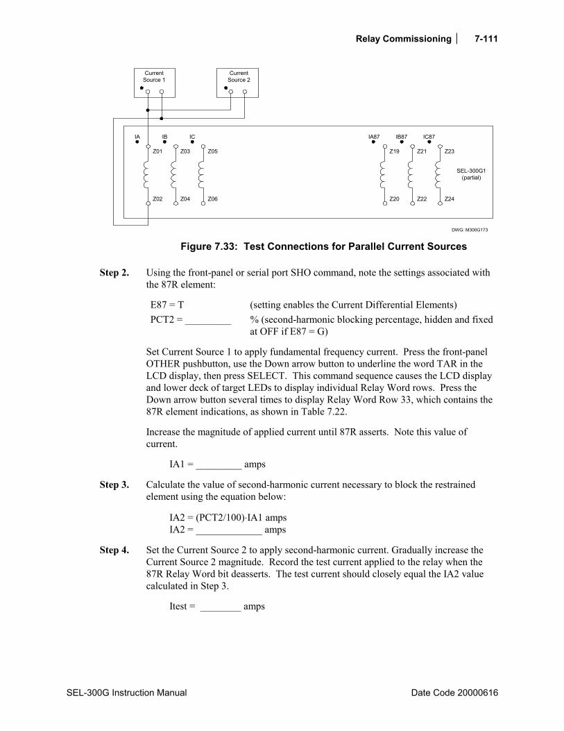
Relay Commissioning 7-111
SEL-300G Instruction Manual Date Code 20000616
DWG: M300G173
Z01
Z02
IA
Z04
Z03
IB
Z06
Z05
IC
Z20
Z19
IA87
Z22
Z21
IB87
Z24
Z23
IC87
SEL-300G1(partial)
CurrentSource 1
CurrentSource 2
Figure 7.33: Test Connections for Parallel Current Sources
Step 2. Using the front-panel or serial port SHO command, note the settings associated with the 87R element:
E87 = T (setting enables the Current Differential Elements) PCT2 = _________ % (second-harmonic blocking percentage, hidden and fixed
at OFF if E87 = G)
Set Current Source 1 to apply fundamental frequency current. Press the front-panel OTHER pushbutton, use the Down arrow button to underline the word TAR in the LCD display, then press SELECT. This command sequence causes the LCD display and lower deck of target LEDs to display individual Relay Word rows. Press the Down arrow button several times to display Relay Word Row 33, which contains the 87R element indications, as shown in Table 7.22.
Increase the magnitude of applied current until 87R asserts. Note this value of current.
IA1 = _________ amps
Step 3. Calculate the value of second-harmonic current necessary to block the restrained element using the equation below:
IA2 = (PCT2/100)⋅IA1 amps IA2 = _____________ amps
Step 4. Set the Current Source 2 to apply second-harmonic current. Gradually increase the Current Source 2 magnitude. Record the test current applied to the relay when the 87R Relay Word bit deasserts. The test current should closely equal the IA2 value calculated in Step 3.
Itest = ________ amps
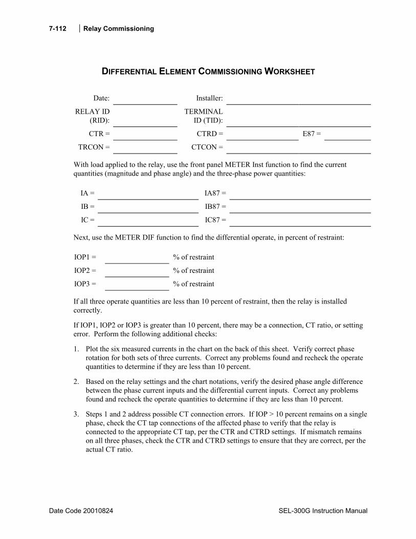
Relay Commissioning
Date Code 20010824 SEL-300G Instruction Manual
7-112
DIFFERENTIAL ELEMENT COMMISSIONING WORKSHEET
Date: Installer:
RELAY ID (RID):
TERMINAL ID (TID):
CTR = CTRD = E87 =
TRCON = CTCON =
With load applied to the relay, use the front panel METER Inst function to find the current quantities (magnitude and phase angle) and the three-phase power quantities:
IA = IA87 =
IB = IB87 =
IC = IC87 =
Next, use the METER DIF function to find the differential operate, in percent of restraint: IOP1 = % of restraint
IOP2 = % of restraint
IOP3 = % of restraint
If all three operate quantities are less than 10 percent of restraint, then the relay is installed correctly.
If IOP1, IOP2 or IOP3 is greater than 10 percent, there may be a connection, CT ratio, or setting error. Perform the following additional checks:
1. Plot the six measured currents in the chart on the back of this sheet. Verify correct phase rotation for both sets of three currents. Correct any problems found and recheck the operate quantities to determine if they are less than 10 percent.
2. Based on the relay settings and the chart notations, verify the desired phase angle difference between the phase current inputs and the differential current inputs. Correct any problems found and recheck the operate quantities to determine if they are less than 10 percent.
3. Steps 1 and 2 address possible CT connection errors. If IOP > 10 percent remains on a single phase, check the CT tap connections of the affected phase to verify that the relay is connected to the appropriate CT tap, per the CTR and CTRD settings. If mismatch remains on all three phases, check the CTR and CTRD settings to ensure that they are correct, per the actual CT ratio.

Relay Commissioning 7-113
SEL-300G Instruction Manual Date Code 20000616
Check List
1. Phasor rotation is as expected.
2. Circle your transformer and ct connection:
If E87 = G, OR
If E87 = T AND
TRCON = GEN, CTCON = Y
TRCON = DABY, CTCON = DAB
TRCON = YDAB, CTCON = Y
TRCON = DACY, CTCON = DAC
TRCON = YDAC, CTCON = Y
TRCON = DABDAB, CTCON = Y
TRCON = DACDAC, CTCON = Y
TRCON = YY, CTCON = Y
Then, phase angles should be 180° apart.
Plot Phasors
If E87 = T AND
TRCON = GEN, CTCON = DAC
TRCON = DABY, CTCON = Y
TRCON = YDAC, CTCON = Y
Then, I87 should lead IW1 by 150°.
If E87 = T AND
TRCON = GEN, CTCON = DAB
TRCON = DACY, CTCON = Y
TRCON = YDAB, CTCON = Y
Then, I87 should lag IW1 by 150°.


SEL-300G Instruction Manual Date Code 20000616
TABLE OF CONTENTS
SECTION 8: MONITORING AND METERING FUNCTIONS ...................8-1
Introduction ...................................................................................................................................8-1 Generator Operating Statistics ......................................................................................................8-1
Generator Hour Meters .........................................................................................................8-1 Generator Accumulated I2
2t...................................................................................................8-2 Generator Average Output Power .........................................................................................8-2 Off-Frequency Operating Time Accumulators .....................................................................8-2 Example PROFILE Command Response..............................................................................8-2 Resetting the Averages and Accumulators............................................................................8-3
Breaker Monitor ............................................................................................................................8-3 Breaker Monitor Operation Example....................................................................................8-3
0% to 10% Breaker Wear ..............................................................................................8-3 10% to 25% Breaker Wear ............................................................................................8-3 25% to 50% Breaker Wear ............................................................................................8-3 50% to 100% Breaker Wear ..........................................................................................8-4
Breaker Monitor Output ........................................................................................................8-9 Example Applications ...................................................................................................8-9
View or Reset Breaker Monitor Information ........................................................................8-9 Via Serial Port ...............................................................................................................8-9 Via Front Panel............................................................................................................8-10
Determination of Relay Initiated Trips and Externally Initiated Trips ...............................8-10 Factory Default Setting Example ................................................................................8-10
Station DC Battery Monitor........................................................................................................8-10 View Station DC Battery Voltage.......................................................................................8-11
Via Serial Port .............................................................................................................8-11 Via Front Panel............................................................................................................8-11
Analyze Station DC Battery Voltage ..................................................................................8-11 Station DC Battery Voltage Dips During Circuit Breaker Tripping...........................8-11 Station DC Battery Voltage Dips During Circuit Breaker Closing.............................8-11
Operation of Station DC Battery Monitor When AC Voltage is Powering the Relay........8-12 Differential Metering ..................................................................................................................8-12
View Differential Metering Information.............................................................................8-12 Via Serial Port .............................................................................................................8-12 Via Front Panel............................................................................................................8-12
Energy Metering..........................................................................................................................8-12 View or Reset Energy Metering Information......................................................................8-12
Via Serial Port .............................................................................................................8-12 Via Front Panel............................................................................................................8-13
Energy Metering Updating and Storage..............................................................................8-13 Maximum/Minimum Metering ...................................................................................................8-13
View or Reset Maximum/Minimum Metering Information................................................8-13 Via Serial Port .............................................................................................................8-13 Via Front Panel............................................................................................................8-13
Maximum/Minimum Metering Updating and Storage........................................................8-14

ii Monitoring and Metering Functions
Date Code 20000616 SEL-300G Instruction Manual
FIGURES Figure 8.1: Breaker Monitor Accumulates 10% Wear............................................................................8-5 Figure 8.2: Breaker Monitor Accumulates 25% Wear............................................................................8-6 Figure 8.3: Breaker Monitor Accumulates 50% Wear............................................................................8-7 Figure 8.4: Breaker Monitor Accumulates 100% Wear..........................................................................8-8
Monitoring and Metering Functions 8-1
SEL-300G Instruction Manual Date Code 20000616
SECTION 8: MONITORING AND METERING FUNCTIONS
INTRODUCTION The SEL-300G Relay’s monitoring functions include:
• Generator Operating Statistics • Breaker Monitor • Station DC Battery Monitor
In addition to instantaneous and demand metering, the SEL-300G Relay’s additional metering functions include:
• Differential Metering • Energy Metering • Maximum/Minimum Metering
This section explains these functions in detail.
GENERATOR OPERATING STATISTICS The SEL-300G Relay helps track the performance and utilization of the protected generator by tracking several generator operating statistics such as:
• Total Generator Running Hours • Total Generator Stopped Hours • Generator Full Load Hours • Percent of time running • Accumulated generator I2
2t • Average real and reactive power outputs • Average power factor
In addition, the relay records the time-of-operation in each 0.1 Hz frequency band between 40 and 70 Hz. This data is updated each second, then stored in nonvolatile memory on a daily basis at 23:50 hours. All the data listed above, plus the present 81AC Off-Frequency Time Accumulator values can be viewed or reset using the serial port PROFILE command.
Generator Hour Meters
The relay provides three hour meters plus a Time Running percentage to help record generator utilization. The relay considers the generator stopped any time the three-pole open (3PO) Relay Word bit is asserted (logical 1). As shown in Section 2: Relay Element Settings, 3PO asserts when all three phase current magnitudes are below the 50L setting and the 52A Relay Word bit is deasserted (logical 0). The relay considers the generator running any time the 3PO Relay Word bit is deasserted.
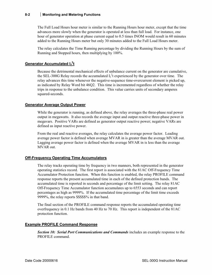
8-2 Monitoring and Metering Functions
Date Code 20000616 SEL-300G Instruction Manual
The Full Load Hours hour meter is similar to the Running Hours hour meter, except that the time advances more slowly when the generator is operated at less than full load. For instance, one hour of generator operation at phase current equal to 0.5 times INOM would result in 60 minutes added to the Running Hours meter but only 30 minutes added to the Full Load Hours meter.
The relay calculates the Time Running percentage by dividing the Running Hours by the sum of Running and Stopped hours, then multiplying by 100%.
Generator Accumulated I22t
Because the detrimental mechanical effects of unbalance current on the generator are cumulative, the SEL-300G Relay records the accumulated I2
2t experienced by the generator over time. The relay advances this time whenever the negative-sequence time-overcurrent element is picked up, as indicated by Relay Word bit 46Q2. This time is incremented regardless of whether the relay trips in response to the unbalance condition. This value carries units of secondary amperes squared-seconds.
Generator Average Output Power
While the generator is running, as defined above, the relay averages the three-phase real power output in megawatts. It also records the average input and output reactive three-phase power in megavars. Positive VARs are defined as generator output reactive power; negative VARs are defined as input reactive power.
From the real and reactive averages, the relay calculates the average power factor. Leading average power factor is defined when average MVAR in is greater than the average MVAR out. Lagging average power factor is defined when the average MVAR in is less than the average MVAR out.
Off-Frequency Operating Time Accumulators
The relay tracks operating time by frequency in two manners, both represented in the generator operating statistics record. The first report is associated with the 81AC Off-Frequency Time Accumulator Protection function. When this function is enabled, the relay PROFILE command response reports the present accumulated time in each of the defined protection bands. The accumulated time is reported in seconds and percentage of the limit setting. The relay 81AC Off-Frequency Time Accumulator function accumulates up to 6553 seconds and can report percentages as high as 9999%. If the accumulated time percentage of the limit time exceeds 9999%, the relay reports $$$$$% in that band.
The final section of the PROFILE command response reports the accumulated operating time overfrequency in 0.1 Hz bands from 40 Hz to 70 Hz. This report is independent of the 81AC protection function.
Example PROFILE Command Response
Section 10: Serial Port Communications and Commands includes an example response to the PROFILE command.
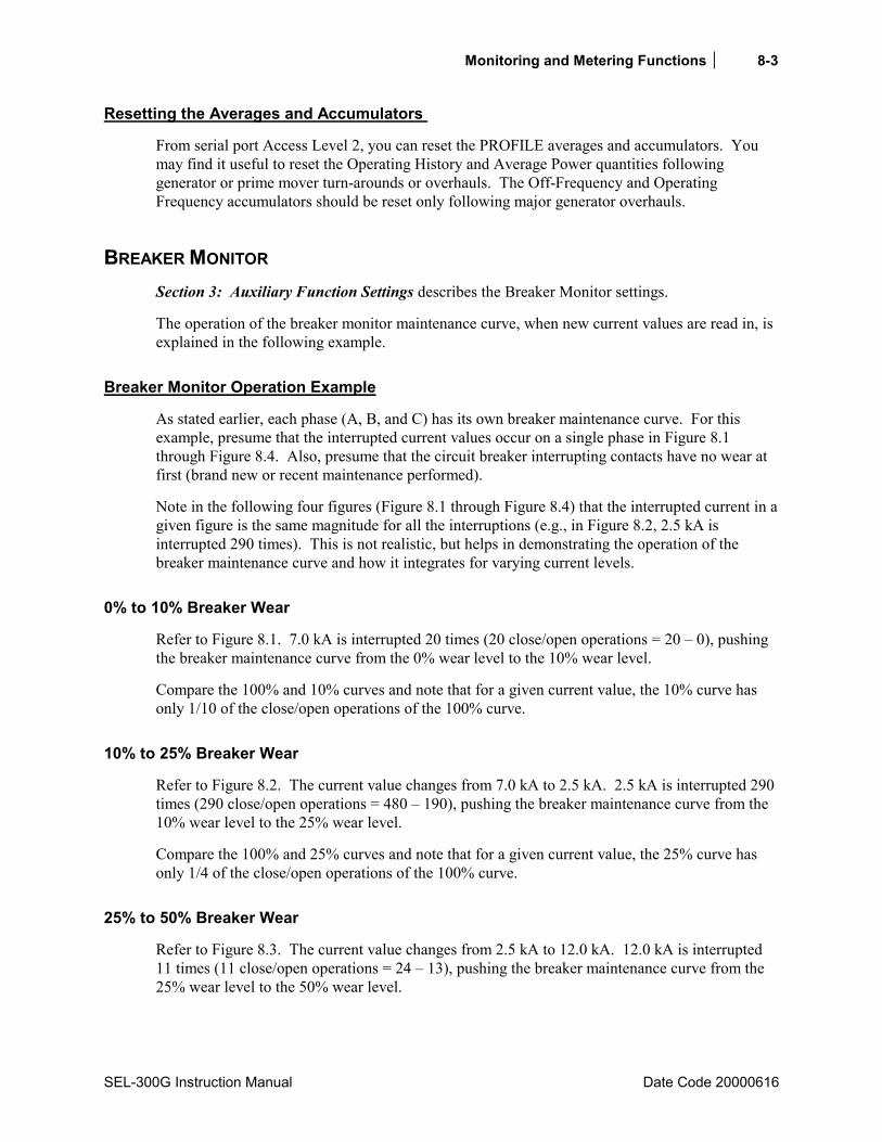
Monitoring and Metering Functions 8-3
SEL-300G Instruction Manual Date Code 20000616
Resetting the Averages and Accumulators
From serial port Access Level 2, you can reset the PROFILE averages and accumulators. You may find it useful to reset the Operating History and Average Power quantities following generator or prime mover turn-arounds or overhauls. The Off-Frequency and Operating Frequency accumulators should be reset only following major generator overhauls.
BREAKER MONITOR Section 3: Auxiliary Function Settings describes the Breaker Monitor settings.
The operation of the breaker monitor maintenance curve, when new current values are read in, is explained in the following example.
Breaker Monitor Operation Example
As stated earlier, each phase (A, B, and C) has its own breaker maintenance curve. For this example, presume that the interrupted current values occur on a single phase in Figure 8.1 through Figure 8.4. Also, presume that the circuit breaker interrupting contacts have no wear at first (brand new or recent maintenance performed).
Note in the following four figures (Figure 8.1 through Figure 8.4) that the interrupted current in a given figure is the same magnitude for all the interruptions (e.g., in Figure 8.2, 2.5 kA is interrupted 290 times). This is not realistic, but helps in demonstrating the operation of the breaker maintenance curve and how it integrates for varying current levels.
0% to 10% Breaker Wear
Refer to Figure 8.1. 7.0 kA is interrupted 20 times (20 close/open operations = 20 – 0), pushing the breaker maintenance curve from the 0% wear level to the 10% wear level.
Compare the 100% and 10% curves and note that for a given current value, the 10% curve has only 1/10 of the close/open operations of the 100% curve.
10% to 25% Breaker Wear
Refer to Figure 8.2. The current value changes from 7.0 kA to 2.5 kA. 2.5 kA is interrupted 290 times (290 close/open operations = 480 – 190), pushing the breaker maintenance curve from the 10% wear level to the 25% wear level.
Compare the 100% and 25% curves and note that for a given current value, the 25% curve has only 1/4 of the close/open operations of the 100% curve.
25% to 50% Breaker Wear
Refer to Figure 8.3. The current value changes from 2.5 kA to 12.0 kA. 12.0 kA is interrupted 11 times (11 close/open operations = 24 – 13), pushing the breaker maintenance curve from the 25% wear level to the 50% wear level.

8-4 Monitoring and Metering Functions
Date Code 20000616 SEL-300G Instruction Manual
Compare the 100% and 50% curves and note that for a given current value, the 50% curve has only 1/2 of the close/open operations of the 100% curve.
50% to 100% Breaker Wear
Refer to Figure 8.4. The current value changes from 12.0 kA to 1.5 kA. 1.5 kA is interrupted 3000 times (3000 close/open operations = 6000 – 3000), pushing the breaker maintenance curve from the 50% wear level to the 100% wear level.
When the breaker maintenance curve reaches 100% for a particular phase, the percentage wear remains at 100% (even if additional current is interrupted), until reset by the BRE R command (see View or Reset Breaker Monitor Information that follows later). The current and trip counts continue to be accumulated, until reset by the BRE R command.
Additionally, logic outputs assert for alarm or other control applications – see the following discussion.

Monitoring and Metering Functions 8-5
SEL-300G Instruction Manual Date Code 20000616
Num
ber
of C
lose
/Ope
nO
pera
tions
kA Interrupted perOperation
.510 1 2 43 765 9 108
2
3
5
4
67
98
100
2
3
DWG: M300G132
3020 40 50
6
4
5
6
87
91000
10%
2
4
3
5
78
10,0009
100%
Figure 8.1: Breaker Monitor Accumulates 10% Wear

8-6 Monitoring and Metering Functions
Date Code 20000616 SEL-300G Instruction Manual
DWG: M300G133
10%
100%10,000
1000
2
3
4
5
6789
100
2
3
4
5
6789
10
2
3
4
5
6789
1 2 3 4 5 6 7 8 9 5040302010
Num
ber
of C
lose
/Ope
nO
pera
tions
kA Interrupted perOperation
.5
25%
Figure 8.2: Breaker Monitor Accumulates 25% Wear
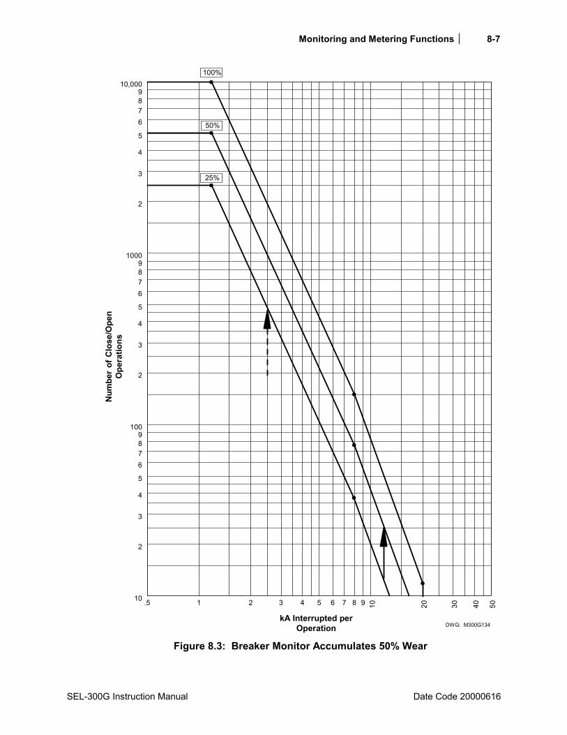
Monitoring and Metering Functions 8-7
SEL-300G Instruction Manual Date Code 20000616
DWG: M300G134
100%10,000
1000
2
3
4
5
6789
100
2
3
4
5
6789
10
2
3
4
5
6789
1 2 3 4 5 6 7 8 9 5040302010
Num
ber
of C
lose
/Ope
nO
pera
tions
kA Interrupted perOperation
.5
25%
50%
Figure 8.3: Breaker Monitor Accumulates 50% Wear
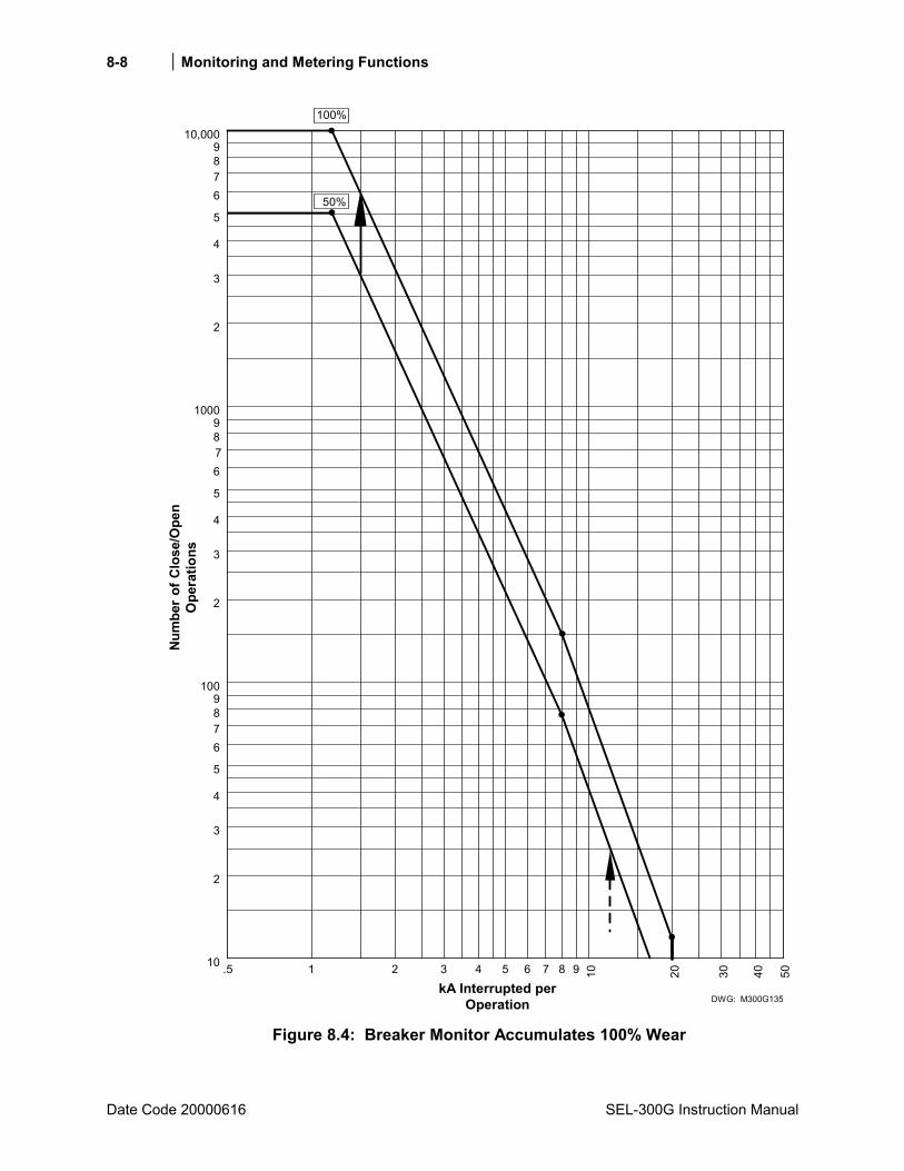
8-8 Monitoring and Metering Functions
Date Code 20000616 SEL-300G Instruction Manual
Num
ber
of C
lose
/Ope
nO
pera
tions
kA Interrupted perOperation
10 .5 1 2 3 4 75 6 98 10
6
3
2
4
5
78
1009
2
DWG: M300G135
3020 40 50
5
3
4
67
1000
89
2
3
4
9
6
5
78
50%
10,000100%
Figure 8.4: Breaker Monitor Accumulates 100% Wear
Monitoring and Metering Functions 8-9
SEL-300G Instruction Manual Date Code 20000616
Breaker Monitor Output
When the breaker maintenance curve for a particular phase (A, B, or C) reaches the 100% wear level (see Figure 8.4), a corresponding Relay Word bit (BCWA, BCWB, or BCWC) asserts.
Relay Word bit Definition
BCWA A-phase breaker contact wear has reached the 100% wear level BCWB B-phase breaker contact wear has reached the 100% wear level BCWC C-phase breaker contact wear has reached the 100% wear level BCW BCWA + BCWB + BCWC
Example Applications
These logic outputs can be used to alarm:
OUT107 = …+ BCW +…
View or Reset Breaker Monitor Information
Accumulated breaker wear/operations data is retained if the relay loses power. The accumulated data can be reset only if the BRE R command is executed (see the following discussion on the BRE R command).
Via Serial Port
See BRE Command (Breaker Monitor Data) in Section 10: Serial Port Communications and Commands. The BRE command displays the following information:
• Accumulated number of relay initiated trips • Accumulated interrupted current from relay initiated trips • Accumulated number of externally initiated trips • Accumulated interrupted current from externally initiated trips • Percent circuit breaker contact wear for each phase • Date when the preceding items were last reset (via the BRE R command)
See BRE n Command (Preload/Reset Breaker Wear) in Section 10: Serial Port Communications and Commands. The BRE W command allows the percent breaker wear to be preloaded for each individual phase.
The BRE R command resets the accumulated values and the percent wear for all three phases. For example, if breaker contact wear has reached the 100% wear level for A-phase, the corresponding Relay Word bit BCWA asserts (BCWA = logical 1). Execution of the BRE R command resets the wear levels for all three phases back to 0% and consequently causes Relay Word bit BCWA to deassert (BCWA = logical 0).
8-10 Monitoring and Metering Functions
Date Code 20000616 SEL-300G Instruction Manual
Via Front Panel
The information and reset functions available via the previously discussed serial port commands BRE and BRE R are also available via the front-panel OTHER pushbutton. See Figure 9.3 in Section 9: Front-Panel Operation.
Determination of Relay Initiated Trips and Externally Initiated Trips
See BRE Command (Breaker Monitor Data) in Section 10: Serial Port Communications and Commands. Note in the BRE command response that the accumulated number of trips and accumulated interrupted current are separated into two groups of data: that generated by relay initiated trips (Int Trips) and that generated by externally initiated trips (Ext Trips). The categorization of this data is determined by the status of the TRIP Relay Word bit when the SELOGIC® Control Equation breaker monitor initiation setting BKMON operates.
Refer to Figure 3.11 and accompanying explanation in Section 3: Auxiliary Function Settings. If BKMON newly asserts (logical 0 to logical 1 transition), the relay reads in the current values (Phases A, B, and C). Now the decision has to be made: where is this current and trip count information accumulated? Is it under relay initiated trips or externally initiated trips?
To make this determination, the status of the TRIP Relay Word bit is checked at the instant BKMON newly asserts (TRIP is the logic output of Figure 4.6). If TRIP is asserted (TRIP = logical 1), the current and trip count information is accumulated under relay initiated trips (Int Trips). If TRIP is deasserted (TRIP = logical 0), the current and trip count information is accumulated under externally initiated trips (Ext Trips).
Regardless of whether the current and trip count information is accumulated under relay initiated trips or externally initiated trips, this same information is routed to the breaker maintenance curve for continued breaker wear integration (see Figure 8.1 through Figure 8.4).
Factory Default Setting Example
As discussed previously, the SELOGIC Control Equation breaker monitor initiation factory default setting is:
BKMON = TRIP1
Thus, any new assertion of BKMON will be deemed a relay trip, and the current and trip count information is accumulated under relay initiated trips (Int Trips).
STATION DC BATTERY MONITOR The station dc battery monitor in the SEL-300G Relay can alarm for under- or overvoltage dc battery conditions and give a view of how much the station dc battery voltage dips when tripping, closing, and other dc control functions take place. The monitor measures the station dc battery voltage applied to the rear-panel terminals labeled POWER, Z25, and Z26. Applications of the DCHIP and DCLOP settings and DCHI and DCLO Relay Word bits are discussed in detail in Section 3: Auxiliary Function Settings.
Monitoring and Metering Functions 8-11
SEL-300G Instruction Manual Date Code 20000616
View Station DC Battery Voltage
Via Serial Port
See MET Command (Metering Data) – Instantaneous Metering in Section 10: Serial Port Communications and Commands. The MET command displays the station dc battery voltage (labeled VDC).
Via Front Panel
The information available via the previously discussed MET serial port command is also available via the front-panel MET pushbutton. See Figure 9.2 in Section 9: Front-Panel Operation.
Analyze Station DC Battery Voltage
See Standard 15/30-Cycle Event Reports in Section 11: Event Reports and SER Functions. The station dc battery voltage is displayed in column Vdc in the example event report in Figure 11.2. Changes in station dc battery voltage for an event (e.g., circuit breaker tripping) can be observed. Use the EVE command to retrieve event reports as discussed in Section 12: Maintain and Troubleshoot Relay.
Station DC Battery Voltage Dips During Circuit Breaker Tripping
Event reports are generated automatically when the TRIP1 through TRIP4 Relay Word bits assert. For example, output contact OUT101 is set to trip:
OUT101 = TRIP1
Anytime output contact OUT101 closes and energizes the circuit breaker trip coil, any dip in station dc battery voltage can be observed in column Vdc in the event report.
Station DC Battery Voltage Dips During Circuit Breaker Closing
To generate an event report when the SEL-300G Relay closes the circuit breaker, make the SELOGIC Control Equation event report generation setting:
ER = /OUT105 + ...
In this example, output contact OUT105 is set to close:
OUT105 = CLOSE (CLOSE is the logic output of Figure 4.8)
Anytime output contact OUT105 closes and energizes the circuit breaker close coil, any dip in station dc battery voltage can be observed in column Vdc in the event report.
This event report generation setting (ER = /OUT105 + ...) might be made just as a testing setting. Generate several event reports when doing circuit breaker close testing and observe the “signature” of the station dc battery voltage in column Vdc in the event reports.

8-12 Monitoring and Metering Functions
Date Code 20000616 SEL-300G Instruction Manual
Operation of Station DC Battery Monitor When AC Voltage is Powering the Relay
If the SEL-300G Relay has a 125/250 Vac/Vdc supply, it can be powered by ac voltage (85 to 264 Vac) connected to the rear-panel terminals labeled POWER. When powering the relay with ac voltage, the dc voltage elements in Figure 3.4 see the average of the sampled ac voltage powering the relay – which is very near zero volts (as displayed in column Vdc in event reports). Thus, pickup settings DCLOP and DCHIP should be set off (DCLOP = OFF, DCHIP = OFF) – they are of no real use.
If a “raw” event report is displayed (with the EVE R command), column Vdc will display the sampled ac voltage waveform rather than the average.
DIFFERENTIAL METERING
View Differential Metering Information
Via Serial Port
See MET Command (Metering Data), MET DIF – Differential Metering (Model 0300G1 and Model 0300G3) in Section 10: Serial Port Communications and Commands. The MET DIF command displays the following values:
Operate Currents Winding 1, Winding 2, and Winding 3 in multiples of TAP and percent (serial port) or per unit (front-panel IMM) of their respective restraint quantities.
Restraint Currents Winding 1, Winding 2, and Winding 3 in multiples of TAP.
Second-Harmonic Currents Winding 1, Winding 2, and Winding 3 in multiples of TAP and percent of their respective operate quantities.
Via Front Panel
The meter function is also available via the front-panel METER pushbutton. See Figure 9.2 in Section 9: Front-Panel Operation.
ENERGY METERING
View or Reset Energy Metering Information
Via Serial Port
See MET Command (Metering Data), MET E – Energy Metering in Section 10: Serial Port Communications and Commands. The MET E command displays accumulated single- and three-phase megawatt and megavar hours. The MET RE command resets the accumulated single- and three-phase megawatt and megavar hours.
Monitoring and Metering Functions 8-13
SEL-300G Instruction Manual Date Code 20000616
Note: When open-delta PTs are applied, (DELTA_Y = D), the relay displays three-phase energy quantities only.
Via Front Panel
The information and reset functions available via the previously discussed serial port commands MET E and MET RE are also available via the front-panel METER pushbutton. See Figure 9.2 in Section 9: Front-Panel Operation.
Energy Metering Updating and Storage
The SEL-300G Relay updates energy values approximately every 2 seconds.
The relay stores energy values to nonvolatile storage once per day (it overwrites the previous stored value). Should the relay lose control power, it will restore the energy values saved by the relay at 23:50 hours on the previous day.
MAXIMUM/MINIMUM METERING
View or Reset Maximum/Minimum Metering Information
Via Serial Port
See MET Command (Metering Data), MET M – Maximum/Minimum Metering in Section 10: Serial Port Communications and Commands. The MET M command displays maximum/minimum metering for the following values:
Currents IA,B,C,N Input currents (A primary) IG Residual ground current (A primary; IG = 3I0 = IA + IB + IC) IA87,B87,C87 87-Input currents (A primary, Models 0300G1, and 0300G3)
Voltages VA,B,C,N Input voltages (kV primary, DELTA_Y = Y) VAB,BC,CA,N Input voltages (kV primary, DELTA_Y = D) Vs Input voltage (kV primary, Models 0300G2 and 0300G3) VP3, VN3 Neutral and terminal third-harmonic voltages
Power MW3P Three-phase megawatts MVAR3P Three-phase megavars
The MET RM command resets the maximum/minimum metering values.
Via Front Panel
The information and reset functions available via the previously discussed serial port commands MET M and MET RM are also available via the front-panel METER pushbutton. See Figure 9.2 in Section 9: Front-Panel Operation.

8-14 Monitoring and Metering Functions
Date Code 20000616 SEL-300G Instruction Manual
Maximum/Minimum Metering Updating and Storage
The SEL-300G Relay updates maximum/minimum values, if the following conditions are met:
• A generator fault is not detected. • The metering value is above the previous maximum or below the previous minimum for
2 cycles. • For phase voltage values, the voltage is above 13 V secondary. • For neutral voltage values, the voltage is above 3 V secondary. • For third-harmonic voltage values, the voltage is above 3 V secondary. • For current values, the currents are above:
• 0.25 A secondary 5 A nominal • 0.05 A secondary 1 A nominal
• Megawatt and megavar values are subject to the above voltage and current thresholds.
The SEL-300G Relay stores maximum/minimum values to nonvolatile storage once per day (it overwrites the previous stored value if it is exceeded). Should the relay lose control power, it will restore the maximum/minimum values saved by the relay at 23:50 hours on the previous day.
Max/min recording is suspended and the FAULT Relay Word bit asserted if any of the following protection elements pick up: 21P1, 21P2, 51N, 50N1, 50N2, 51P, 51G, 51C, 51V, 46Q1, 46Q2, 64G1, 64G2, INAD, 60LOP, 87R, 87U, 87N1P, or 87N2P.
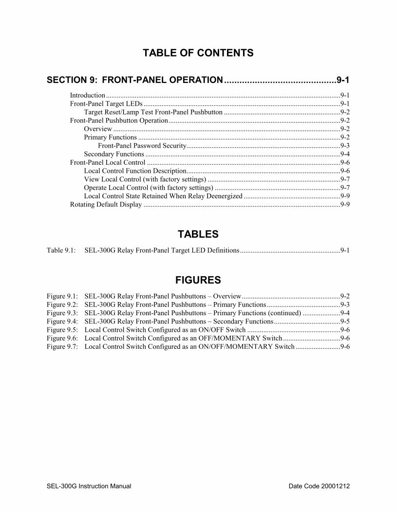
SEL-300G Instruction Manual Date Code 20001212
TABLE OF CONTENTS
SECTION 9: FRONT-PANEL OPERATION............................................9-1
Introduction ...................................................................................................................................9-1 Front-Panel Target LEDs ..............................................................................................................9-1
Target Reset/Lamp Test Front-Panel Pushbutton .................................................................9-2 Front-Panel Pushbutton Operation................................................................................................9-2
Overview ...............................................................................................................................9-2 Primary Functions .................................................................................................................9-2
Front-Panel Password Security......................................................................................9-3 Secondary Functions .............................................................................................................9-4
Front-Panel Local Control ............................................................................................................9-6 Local Control Function Description......................................................................................9-6 View Local Control (with factory settings) ..........................................................................9-7 Operate Local Control (with factory settings) ......................................................................9-7 Local Control State Retained When Relay Deenergized ......................................................9-9
Rotating Default Display ..............................................................................................................9-9
TABLES Table 9.1: SEL-300G Relay Front-Panel Target LED Definitions........................................................9-1
FIGURES Figure 9.1: SEL-300G Relay Front-Panel Pushbuttons – Overview.......................................................9-2 Figure 9.2: SEL-300G Relay Front-Panel Pushbuttons – Primary Functions.........................................9-3 Figure 9.3: SEL-300G Relay Front-Panel Pushbuttons – Primary Functions (continued) .....................9-4 Figure 9.4: SEL-300G Relay Front-Panel Pushbuttons – Secondary Functions.....................................9-5 Figure 9.5: Local Control Switch Configured as an ON/OFF Switch ....................................................9-6 Figure 9.6: Local Control Switch Configured as an OFF/MOMENTARY Switch ................................9-6 Figure 9.7: Local Control Switch Configured as an ON/OFF/MOMENTARY Switch .........................9-6

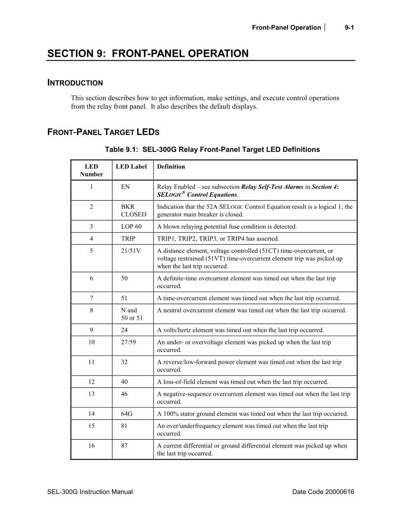
Front-Panel Operation 9-1
SEL-300G Instruction Manual Date Code 20000616
SECTION 9: FRONT-PANEL OPERATION
INTRODUCTION This section describes how to get information, make settings, and execute control operations from the relay front panel. It also describes the default displays.
FRONT-PANEL TARGET LEDS
Table 9.1: SEL-300G Relay Front-Panel Target LED Definitions
LED Number
LED Label Definition
1 EN Relay Enabled – see subsection Relay Self-Test Alarms in Section 4: SELOGIC® Control Equations.
2 BKR CLOSED
Indication that the 52A SELOGIC Control Equation result is a logical 1; the generator main breaker is closed.
3 LOP 60 A blown relaying potential fuse condition is detected.
4 TRIP TRIP1, TRIP2, TRIP3, or TRIP4 has asserted.
5 21/51V A distance element, voltage controlled (51CT) time-overcurrent, or voltage restrained (51VT) time-overcurrent element trip was picked up when the last trip occurred.
6 50 A definite-time overcurrent element was timed out when the last trip occurred.
7 51 A time-overcurrent element was timed out when the last trip occurred.
8 N and 50 or 51
A neutral overcurrent element was timed out when the last trip occurred.
9 24 A volts/hertz element was timed out when the last trip occurred.
10 27/59 An under- or overvoltage element was picked up when the last trip occurred.
11 32 A reverse/low-forward power element was timed out when the last trip occurred.
12 40 A loss-of-field element was timed out when the last trip occurred.
13 46 A negative-sequence overcurrent element was timed out when the last trip occurred.
14 64G A 100% stator ground element was timed out when the last trip occurred.
15 81 An over/underfrequency element was timed out when the last trip occurred.
16 87 A current differential or ground differential element was picked up when the last trip occurred.
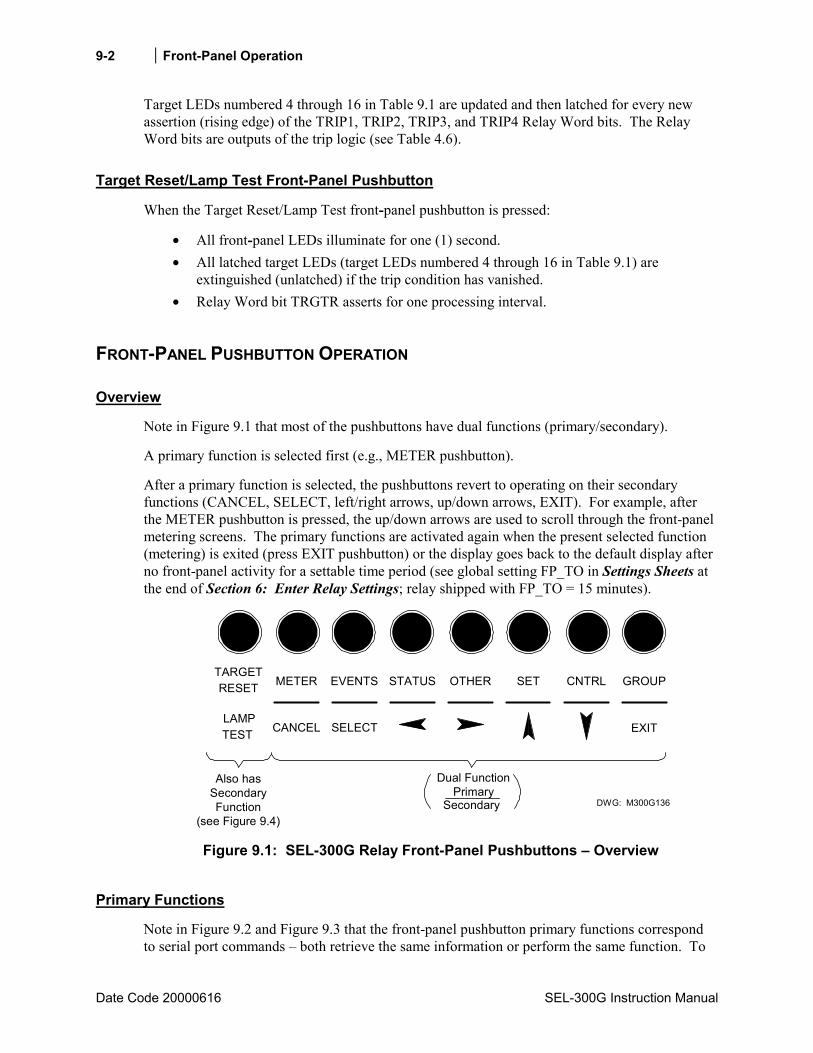
Front-Panel Operation
Date Code 20000616 SEL-300G Instruction Manual
9-2
Target LEDs numbered 4 through 16 in Table 9.1 are updated and then latched for every new assertion (rising edge) of the TRIP1, TRIP2, TRIP3, and TRIP4 Relay Word bits. The Relay Word bits are outputs of the trip logic (see Table 4.6).
Target Reset/Lamp Test Front-Panel Pushbutton
When the Target Reset/Lamp Test front-panel pushbutton is pressed:
• All front-panel LEDs illuminate for one (1) second. • All latched target LEDs (target LEDs numbered 4 through 16 in Table 9.1) are
extinguished (unlatched) if the trip condition has vanished. • Relay Word bit TRGTR asserts for one processing interval.
FRONT-PANEL PUSHBUTTON OPERATION
Overview
Note in Figure 9.1 that most of the pushbuttons have dual functions (primary/secondary).
A primary function is selected first (e.g., METER pushbutton).
After a primary function is selected, the pushbuttons revert to operating on their secondary functions (CANCEL, SELECT, left/right arrows, up/down arrows, EXIT). For example, after the METER pushbutton is pressed, the up/down arrows are used to scroll through the front-panel metering screens. The primary functions are activated again when the present selected function (metering) is exited (press EXIT pushbutton) or the display goes back to the default display after no front-panel activity for a settable time period (see global setting FP_TO in Settings Sheets at the end of Section 6: Enter Relay Settings; relay shipped with FP_TO = 15 minutes).
GROUP
LAMPTEST CANCEL SELECT
TARGETRESET EVENTSMETER
EXIT
SETSTATUS OTHER CNTRL
DWG: M300G136Secondary
Dual FunctionPrimary
Also hasSecondaryFunction
(see Figure 9.4) Figure 9.1: SEL-300G Relay Front-Panel Pushbuttons – Overview
Primary Functions
Note in Figure 9.2 and Figure 9.3 that the front-panel pushbutton primary functions correspond to serial port commands – both retrieve the same information or perform the same function. To
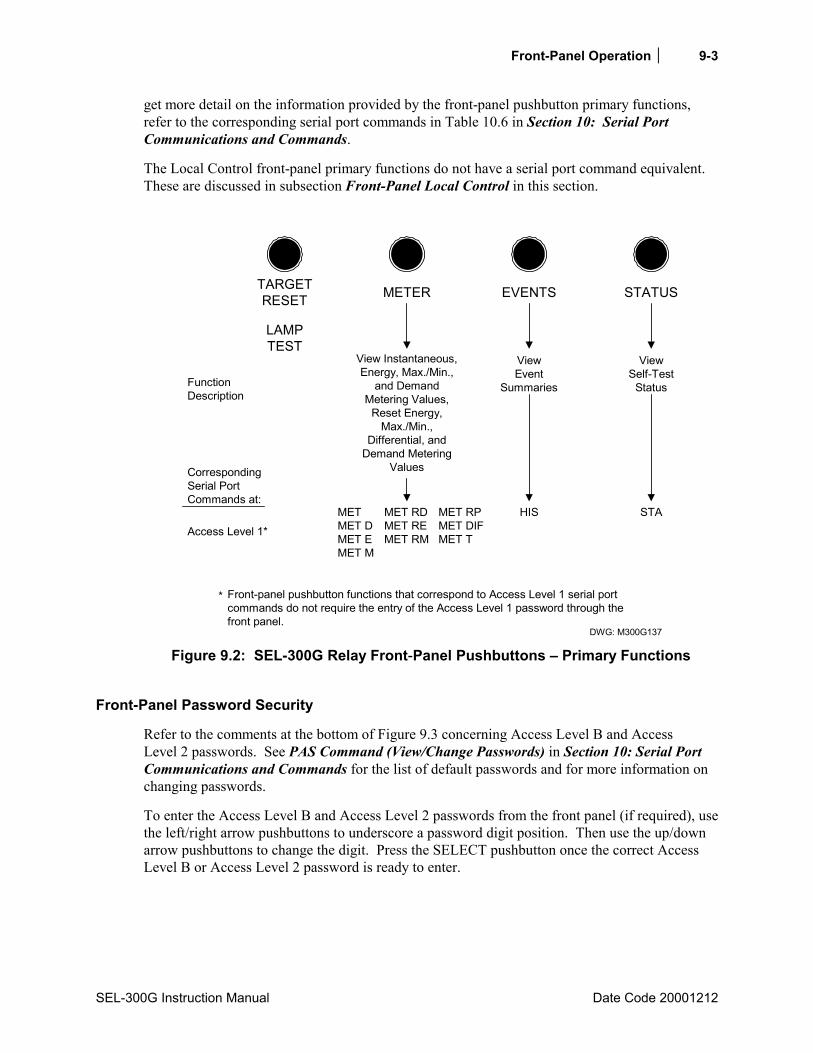
Front-Panel Operation 9-3
SEL-300G Instruction Manual Date Code 20001212
get more detail on the information provided by the front-panel pushbutton primary functions, refer to the corresponding serial port commands in Table 10.6 in Section 10: Serial Port Communications and Commands.
The Local Control front-panel primary functions do not have a serial port command equivalent. These are discussed in subsection Front-Panel Local Control in this section.
TARGETRESET
LAMPTEST
METER EVENTS STATUS
DWG: M300G137
View Instantaneous,Energy, Max./Min.,
and DemandMetering Values,
Reset Energy,Max./Min.,
Differential, andDemand Metering
Values
ViewEvent
Summaries
ViewSelf-Test
Status
HIS STA
FunctionDescription
CorrespondingSerial PortCommands at:
Access Level 1*
Front-panel pushbutton functions that correspond to Access Level 1 serial portcommands do not require the entry of the Access Level 1 password through thefront panel.
*
METMET DMET EMET M
MET RDMET REMET RM
MET RPMET DIFMET T
Figure 9.2: SEL-300G Relay Front-Panel Pushbuttons – Primary Functions
Front-Panel Password Security
Refer to the comments at the bottom of Figure 9.3 concerning Access Level B and Access Level 2 passwords. See PAS Command (View/Change Passwords) in Section 10: Serial Port Communications and Commands for the list of default passwords and for more information on changing passwords.
To enter the Access Level B and Access Level 2 passwords from the front panel (if required), use the left/right arrow pushbuttons to underscore a password digit position. Then use the up/down arrow pushbuttons to change the digit. Press the SELECT pushbutton once the correct Access Level B or Access Level 2 password is ready to enter.

Front-Panel Operation
Date Code 20000616 SEL-300G Instruction Manual
9-4
OTHER SET CNTRL GROUP
DWG: M300G138
Display ActiveSetting Group
Number; ChangeActive Setting
Group
FunctionDescription
CorrespondingSerial PortCommands at:
Access Level 1*
Front-panel pushbutton functions that correspond to Access Level 1 serial port commands do not require theentry of the Access Level 1 password through the front panel.
*
Access Level B**
Access Level 2***
View or Reset BreakerMonitor Data; View orChange Date or Time;View Asserted Relay
Word Bits
BREDATTIMTAR
BRE R
View or ChangeGroup, Global, or
Serial Port Settings;Change Passwords
SHO nSHO GSHO P
SET nSET GSET PPAS
Pulse OutputContacts****
View or OperateLocal Control*****
PUL
GRO
GRO n
Front-panel pushbutton functions that correspond to Access Level B serial port commands do require the entryof the Access Level B or Access Level 2 passwords through the front panel if the main board Password jumperis not in place (see Tables 5.5 and 5.6).
Front-panel pushbutton functions that correspond to Access Level 2 serial port commands do require the entryof the Access Level 2 passwords through the front panel if the main board Password jumper is not in place (seeTables 5.5 and 5.6).
Output contacts are pulsed for only 1 second from the front panel.
Local control is not available through the serial port and does not require the entry of a password.
**
***
*********
Figure 9.3: SEL-300G Relay Front-Panel Pushbuttons – Primary Functions
(continued)
Secondary Functions
After a primary function is selected (see Figure 9.2 and Figure 9.3), the pushbuttons revert to operating on their secondary functions (see Figure 9.4).
Use the left/right arrows to underscore a desired function. Then press the SELECT pushbutton to select the function.
Use left/right arrows to underscore a desired setting digit. Then use the up/down arrows to change the digit. After the setting changes are complete, press the SELECT pushbutton to select/enable the setting.
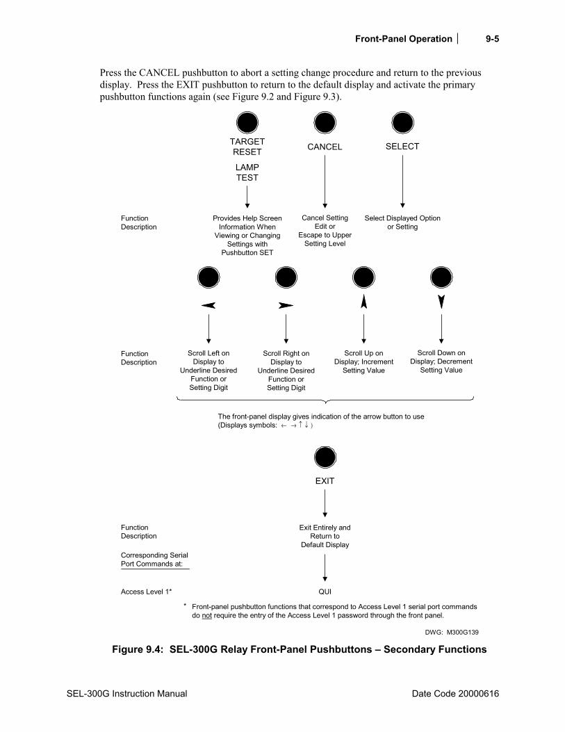
Front-Panel Operation 9-5
SEL-300G Instruction Manual Date Code 20000616
Press the CANCEL pushbutton to abort a setting change procedure and return to the previous display. Press the EXIT pushbutton to return to the default display and activate the primary pushbutton functions again (see Figure 9.2 and Figure 9.3).
CANCEL
DWG: M300G139
Cancel SettingEdit or
Escape to UpperSetting Level
TARGETRESET
LAMPTEST
Provides Help ScreenInformation When
Viewing or ChangingSettings with
Pushbutton SET
FunctionDescription
Scroll Left onDisplay to
Underline DesiredFunction orSetting Digit
Scroll Right onDisplay to
Underline DesiredFunction orSetting Digit
Scroll Up onDisplay; Increment
Setting Value
Scroll Down onDisplay; Decrement
Setting Value
FunctionDescription
Select Displayed Optionor Setting
SELECT
Exit Entirely andReturn to
Default Display
EXIT
The front-panel display gives indication of the arrow button to use(Displays symbols: ← → ↑ ↓ )
QUI
FunctionDescription
Corresponding SerialPort Commands at:
Access Level 1*
Front-panel pushbutton functions that correspond to Access Level 1 serial port commandsdo not require the entry of the Access Level 1 password through the front panel.
*
Figure 9.4: SEL-300G Relay Front-Panel Pushbuttons – Secondary Functions

Front-Panel Operation
Date Code 20000616 SEL-300G Instruction Manual
9-6
FRONT-PANEL LOCAL CONTROL
Local Control Function Description
Use local control to enable/disable schemes, trip/close breakers, etc., via the front panel.
In more specific terms, local control asserts (sets to logical 1) or deasserts (sets to logical 0) what are called local bits LB1 through LB16. These local bits are available as Relay Word bits and are used in SELOGIC Control Equations (see Table 4.6).
Local control can emulate the following switch types in Figure 9.5 through Figure 9.7.
OFF position(logical 0)
ONposition
DWG: M300G144
RelayWord
BitLBnLogical 1 (n=1 through 16)
Figure 9.5: Local Control Switch Configured as an ON/OFF Switch
OFF position(logical 0)
MOMENTARYposition DWG: M300G143
RelayWord
BitLBnLogical 1 (n=1 through 16)
Figure 9.6: Local Control Switch Configured as an OFF/MOMENTARY Switch
OFF position(logical 0)
MOMENTARYposition DWG: M300G145
RelayWord
BitLBnLogical 1 (n=1 through 16)
ONposition
Figure 9.7: Local Control Switch Configured as an ON/OFF/MOMENTARY Switch
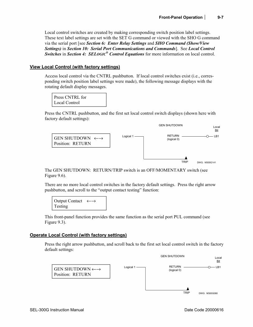
Front-Panel Operation 9-7
SEL-300G Instruction Manual Date Code 20000616
Local control switches are created by making corresponding switch position label settings. These text label settings are set with the SET G command or viewed with the SHO G command via the serial port [see Section 6: Enter Relay Settings and SHO Command (Show/View Settings) in Section 10: Serial Port Communications and Commands]. See Local Control Switches in Section 4: SELOGIC® Control Equations for more information on local control.
View Local Control (with factory settings)
Access local control via the CNTRL pushbutton. If local control switches exist (i.e., corres-ponding switch position label settings were made), the following message displays with the rotating default display messages.
Press CNTRL for Local Control
Press the CNTRL pushbutton, and the first set local control switch displays (shown here with factory default settings):
GEN SHUTDOWN ←→ Position: RETURN
RETURN(logical 0)
TRIP
GEN SHUTDOWN
DWG: M300G141
LocalBit
LB1Logical 1
The GEN SHUTDOWN: RETURN/TRIP switch is an OFF/MOMENTARY switch (see Figure 9.6).
There are no more local control switches in the factory default settings. Press the right arrow pushbutton, and scroll to the “output contact testing” function:
Output Contact ←→ Testing
This front-panel function provides the same function as the serial port PUL command (see Figure 9.3).
Operate Local Control (with factory settings)
Press the right arrow pushbutton, and scroll back to the first set local control switch in the factory default settings:
GEN SHUTDOWN ←→ Position: RETURN
RETURN(logical 0)
TRIP
GEN SHUTDOWN
DWG: M300G080
LocalBit
LB1Logical 1

Front-Panel Operation
Date Code 20000616 SEL-300G Instruction Manual
9-8
Press the SELECT pushbutton, and the operate option for the displayed local control switch displays:
GEN SHUTDOWN TRIP ? Yes No ←→
RETURN(logical 0)
TRIP
GEN SHUTDOWN
DWG: M300G080
LocalBit
LB1Logical 1
Scroll left with the left arrow button and then select “Yes”. The display then shows the new local control switch position:
GEN SHUTDOWN Position: TRIP
RETURN(logical 0)
TRIP
GEN SHUTDOWN
DWG: M300G140
LocalBit
LB1Logical 1
Because this is an OFF/MOMENTARY type switch, the GEN SHUTDOWN switch returns to the RETURN position after momentarily being in the TRIP position. Technically, the GEN SHUTDOWN switch (being an OFF/MOMENTARY type switch) is in the:
TRIP position for one processing interval (1/4 cycle; long enough to assert the correspond-ing local bit LB1 to logical 1)
and then returns to the:
RETURN position (local bit LB1 deasserts to logical 0 again).
On the display, the GEN SHUTDOWN switch is shown to be in the TRIP position for 2 seconds (long enough to be seen), and then it returns to the RETURN position:
GEN SHUTDOWN ←→ Position: RETURN
RETURN(logical 0)
TRIP
GEN SHUTDOWN
DWG: M300G080
LocalBit
LB1Logical 1
See Local Control Switches in Section 4: SELOGIC® Control Equations for details on how local bit outputs LB1 and LB2 are set in SELOGIC Control Equation settings to respectively trip and close a circuit breaker.
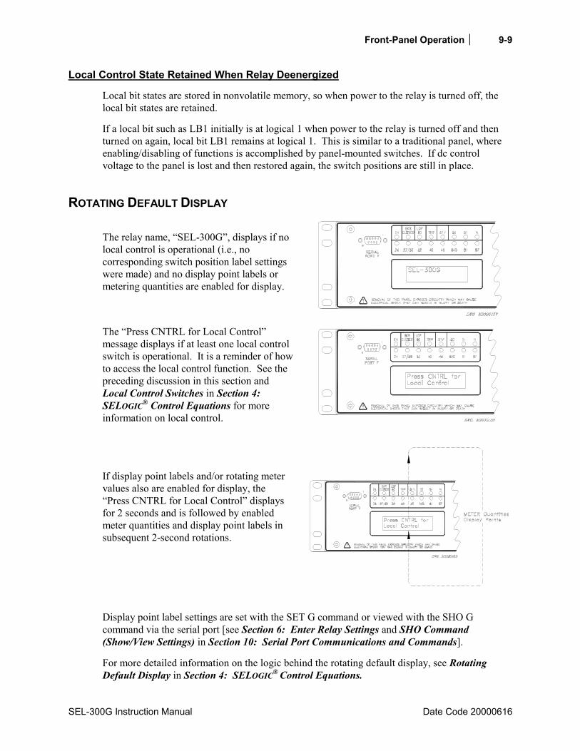
Front-Panel Operation 9-9
SEL-300G Instruction Manual Date Code 20000616
Local Control State Retained When Relay Deenergized
Local bit states are stored in nonvolatile memory, so when power to the relay is turned off, the local bit states are retained.
If a local bit such as LB1 initially is at logical 1 when power to the relay is turned off and then turned on again, local bit LB1 remains at logical 1. This is similar to a traditional panel, where enabling/disabling of functions is accomplished by panel-mounted switches. If dc control voltage to the panel is lost and then restored again, the switch positions are still in place.
ROTATING DEFAULT DISPLAY The relay name, “SEL-300G”, displays if no local control is operational (i.e., no corresponding switch position label settings were made) and no display point labels or metering quantities are enabled for display.
The “Press CNTRL for Local Control” message displays if at least one local control switch is operational. It is a reminder of how to access the local control function. See the preceding discussion in this section and Local Control Switches in Section 4: SELOGIC® Control Equations for more information on local control.
If display point labels and/or rotating meter values also are enabled for display, the “Press CNTRL for Local Control” displays for 2 seconds and is followed by enabled meter quantities and display point labels in subsequent 2-second rotations.
Display point label settings are set with the SET G command or viewed with the SHO G command via the serial port [see Section 6: Enter Relay Settings and SHO Command (Show/View Settings) in Section 10: Serial Port Communications and Commands].
For more detailed information on the logic behind the rotating default display, see Rotating Default Display in Section 4: SELOGIC® Control Equations.


SEL-300G Instruction Manual Date Code 20020206
TABLE OF CONTENTS
SECTION 10: SERIAL PORT COMMUNICATIONS AND COMMANDS .....................................................................................10-1
Introduction .................................................................................................................................10-1 Port Connector and Communications Cables..............................................................................10-1
IRIG-B.................................................................................................................................10-2 SEL-300G to Computer.......................................................................................................10-2 SEL-300G to Modem ..........................................................................................................10-3 SEL-300G to SEL-PRTU....................................................................................................10-4 SEL-300G to SEL-2020 or SEL 2030.................................................................................10-4
Communications Protocol ...........................................................................................................10-5 Hardware Protocol...............................................................................................................10-5 Software Protocols ..............................................................................................................10-6
SEL ASCII Protocol ....................................................................................................10-6 SEL Distributed Port Switch Protocol (LMD) ............................................................10-7 SEL Fast Meter Protocol.............................................................................................10-7 SEL Compressed ASCII Protocol ...............................................................................10-7 Modbus RTU Protocol.................................................................................................10-7
Serial Port Automatic Messages .................................................................................................10-7 Serial Port Access Levels............................................................................................................10-8
Access Level 0.....................................................................................................................10-8 Access Level 1.....................................................................................................................10-8 Access Level B....................................................................................................................10-9 Access Level 2.....................................................................................................................10-9
Command Summary..................................................................................................................10-10 Command Explanations ............................................................................................................10-12
Access Level 0 Commands ...............................................................................................10-12 HELP Command (Display Available Serial Port Commands)..................................10-12 ACC, BAC, and 2AC Commands (Go to Access Level 1, B, or 2) ..........................10-12
Password Requirements and Default Passwords ...............................................10-12 Access Level Attempt (Password Required) .....................................................10-12 Access Level Attempt (Password not Required) ...............................................10-13
Access Level 1 Commands ...............................................................................................10-13 BRE Command (Breaker Monitor Data)...................................................................10-13 DAT Command (View/Change Date) .......................................................................10-14 EVE Command (Event Reports) ...............................................................................10-14 GRO Command (Display Active Setting Group Number)........................................10-14 HIS Command (Event Summaries/History) ..............................................................10-14 IRI Command (Synchronize to IRIG-B Time Code).................................................10-15 MET Command (Metering Data) ..............................................................................10-16
MET k Instantaneous Metering ......................................................................10-16 MET D Demand Metering..............................................................................10-17
MET DIF Differential Metering (Models 0300G1 and 0300G3) ...........................10-18 MET E Energy Metering ................................................................................10-18 MET M Maximum/Minimum Metering .........................................................10-19
MET RD ....................................................................................................................10-20 MET RE.....................................................................................................................10-20
ii Serial Port Communications and Commands
Date Code 20020206 SEL-300G Instruction Manual
MET RM ...................................................................................................................10-20 MET RP.....................................................................................................................10-20 MET T Thermal Metering ......................................................................................10-20 PRO Command (Display Generator Operation Profile) ............................................10-21 QUI Command (Quit Access Level) .........................................................................10-22 SER Command (Sequential Events Recorder Report) ..............................................10-23 SHO Command (Show/View Settings) .....................................................................10-23 STA Command (Relay Self-Test Status)...................................................................10-28
STA Command Row and Column Definitions ..................................................10-28 SYN Command (Synch-Check Function Report) (Models 0300G2 and 0300G3) ...10-28 TAR Command (Display Relay Element Status) ......................................................10-29 TIM Command (View/Change Time) .......................................................................10-31 TRI Command (Trigger Event Report) .....................................................................10-31
Access Level B Commands...............................................................................................10-32 CLO Command (Close Breaker) ...............................................................................10-32 GRO n Command (Change Active Setting Group) ...................................................10-32 OPE n Command (Open Breaker) .............................................................................10-33 PUL Command (Pulse Output Contact) ....................................................................10-34
Access Level 2 Commands ...............................................................................................10-34 BRE n Command (Preload/Reset Breaker Wear)......................................................10-34 CON Command (Control Remote Bit) ......................................................................10-35 COP m n Command (Copy Setting Group)...............................................................10-35 HIS C Command (Clear Event Summaries/History).................................................10-36 PRO R........................................................................................................................10-36 PAS Command (View/Change Passwords)...............................................................10-36 SET Command (Change Settings).............................................................................10-37 STA C........................................................................................................................10-37 SYN R (Models 0300G2, 0300G3) ...........................................................................10-38
Serial Port Error Messages........................................................................................................10-38 Command Summary..................................................................................................................10-41
TABLES Table 10.1: SEL-300G Relay Available Serial Ports ..............................................................................10-1 Table 10.2: Pinout Functions for EIA-232 Serial Ports 2, 3, and F ........................................................10-2 Table 10.3: Terminal Functions for EIA-485 Serial Port 1.....................................................................10-2 Table 10.4: Serial Communications Port Pin/Terminal Function Definitions ........................................10-5 Table 10.5: Serial Port Automatic Messages ..........................................................................................10-8 Table 10.6: Serial Port Command Summary.........................................................................................10-10 Table 10.7: SEL-300G Relay Word and Its Correspondence to TAR Command.................................10-29 Table 10.8: SEL-300G Relay Control Subcommands ..........................................................................10-35 Table 10.9: SEL-300G Error Messages ................................................................................................10-38
FIGURES Figure 10.1: DB-9 Connector Pinout for EIA-232 Serial Ports ..............................................................10-1

Serial Port Communications and Commands 10-1
SEL-300G Instruction Manual Date Code 20000616
SECTION 10: SERIAL PORT COMMUNICATIONS AND COMMANDS
INTRODUCTION Various serial ports are available in the following SEL-300G Relay models:
Table 10.1: SEL-300G Relay Available Serial Ports
Rear Panel Front Panel
Serial Port 1 (EIA-485, 4-wire)
Serial Port 2 (EIA232)
Serial Port 3 (EIA232)
Serial Port F (EIA232)
Connect the serial port to a computer serial port for local communications or to a modem for remote communications. Other devices useful for communications include the SEL-PRTU, the SEL-2020, the SEL-2030, and the SEL2600 / SEL2800. You can use a variety of terminal emulation programs on your personal computer to communicate with the relay. Examples of PC-based terminal emulation programs include: Procomm® Plus, Relay/Gold, Microsoft® Windows® Terminal, SmartCOM, and CROSSTALK®. For the best display, use VT-100 terminal emulation or the closest variation.
The default settings for all serial ports are:
Baud Rate = 2400 Data Bits = 8 Parity = N Stop Bits = 1
To change the port settings, use the SET P command (see Section 6: Enter Relay Settings) or the front-panel SET pushbutton.
PORT CONNECTOR AND COMMUNICATIONS CABLES
Figure 10.1: DB-9 Connector Pinout for EIA-232 Serial Ports
(female chassis connector, as viewed from outside panel)
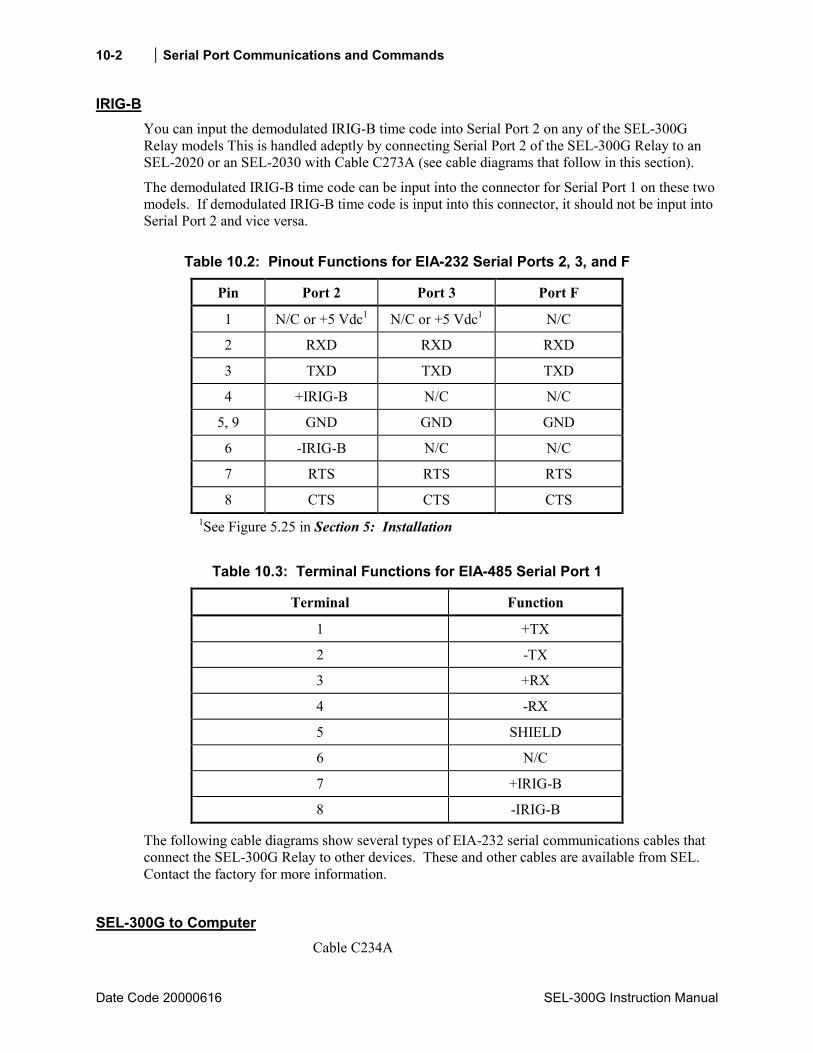
10-2 Serial Port Communications and Commands
Date Code 20000616 SEL-300G Instruction Manual
IRIG-B You can input the demodulated IRIG-B time code into Serial Port 2 on any of the SEL-300G Relay models This is handled adeptly by connecting Serial Port 2 of the SEL-300G Relay to an SEL-2020 or an SEL-2030 with Cable C273A (see cable diagrams that follow in this section).
The demodulated IRIG-B time code can be input into the connector for Serial Port 1 on these two models. If demodulated IRIG-B time code is input into this connector, it should not be input into Serial Port 2 and vice versa.
Table 10.2: Pinout Functions for EIA-232 Serial Ports 2, 3, and F
Pin Port 2 Port 3 Port F
1 N/C or +5 Vdc1 N/C or +5 Vdc1 N/C
2 RXD RXD RXD
3 TXD TXD TXD
4 +IRIG-B N/C N/C
5, 9 GND GND GND
6 -IRIG-B N/C N/C
7 RTS RTS RTS
8 CTS CTS CTS 1See Figure 5.25 in Section 5: Installation
Table 10.3: Terminal Functions for EIA-485 Serial Port 1
Terminal Function
1 +TX
2 -TX
3 +RX
4 -RX
5 SHIELD
6 N/C
7 +IRIG-B
8 -IRIG-B
The following cable diagrams show several types of EIA-232 serial communications cables that connect the SEL-300G Relay to other devices. These and other cables are available from SEL. Contact the factory for more information.
SEL-300G to Computer Cable C234A

Serial Port Communications and Commands 10-3
SEL-300G Instruction Manual Date Code 20000616
SEL-300G Relay 9-Pin Male
D Subconnector
9-Pin DTE* Device 9-Pin Female
D Subconnector
RXD 2 3 TXD TXD 3 2 RXD GND 5 5 GND CTS 8 8 CTS
7 RTS 1 DCD 4 DTR 6 DSR
Cable C227A
SEL-300G Relay
9-Pin Male D Subconnector
25-Pin DTE* Device 25-Pin Female
D Subconnector
GND 5 7 GND TXD 3 3 RXD RXD 2 2 TXD GND 9 1 RTS CTS 8 4 CTS
5 GND 6 8 20
SEL-300G to Modem
Cable C222
SEL-300G Relay
9-Pin Male D Subconnector
DCE** Device 25-Pin Female
D Subconnector
GND 5 7 GND TXD 3 2 TXD (IN) RTS 7 20 DTR (IN)
RXD 2 3 RXD (OUT) GND 9 1 GND CTS 8 8 CD (OUT)

10-4 Serial Port Communications and Commands
Date Code 20000616 SEL-300G Instruction Manual
SEL-300G to SEL-PRTU
Cable C231
SEL-PRTU 9-Pin Male
Round Conxall
SEL-300G Relay 9-Pin Male
D Subconnector
GND 1 5 GND TXD 2 2 RXD RXD 4 3 TXD CTS 5 7 RTS +12 7 8 CTS
GND 9 9 GND
SEL-300G to SEL-2020 or SEL 2030
Cable C273A
SEL-2020/2030
9-Pin Male D Subconnector
SEL-300G Relay 9-Pin Male
D Subconnector
RXD 2 3 TXD TXD 3 2 RXD
IRIG+ 4 4 IRIG+ GND 5 5 GND IRIG- 6 6 IRIG-
RTS 7 8 CTS CTS 8 7 RTS
* DTE = Data Terminal Equipment (Computer, Terminal, Printer, etc.)
** DCE = Data Communications Equipment (Modem, etc.)

Serial Port Communications and Commands 10-5
SEL-300G Instruction Manual Date Code 20020206
Table 10.4: Serial Communications Port Pin/Terminal Function Definitions
Pin Function Definition
N/C No Connection
+5 Vdc (0.5 A limit) 5 Vdc Power Connection
RXD, RX Receive Data
TXD, TX Transmit Data
IRIG-B IRIG-B Time-Code Input
GND Ground
SHIELD Shielded Ground
RTS Request To Send
CTS Clear To Send
DCD Data Carrier Detect
DTR Data Terminal Ready
DSR Data Set Ready
For long-distance communications up to 500 meters and for electrical isolation of communica-tions ports, use the SEL-2800 family of Fiber-Optic Transceivers. Contact SEL for more details on these devices.
COMMUNICATIONS PROTOCOL
Hardware Protocol All EIA-232 serial ports support RTS/CTS hardware handshaking. RTS/CTS handshaking is not supported on the EIA-485 Serial Port 1.
To enable hardware handshaking, use the SET P command (or front-panel SET pushbutton) to set RTSCTS = Y. Disable hardware handshaking by setting RTSCTS = N.
If RTSCTS = N, the relay permanently asserts the RTS line until the buffer is full (for SEL PROTO).
If RTSCTS = Y, the relay deasserts RTS when it is unable to receive characters. If RTSCTS = Y, the relay does not send characters until the CTS input is asserted. If RTSCTS = H, the relay permanently asserts the RTS line (for MOD PROTO) When PROTO = LMD, the RTSCTS setting is hidden and hardware handshaking is disabled.
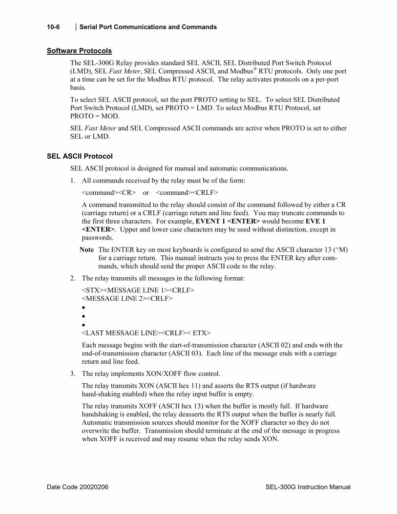
10-6 Serial Port Communications and Commands
Date Code 20020206 SEL-300G Instruction Manual
Software Protocols The SEL-300G Relay provides standard SEL ASCII, SEL Distributed Port Switch Protocol (LMD), SEL Fast Meter, SEL Compressed ASCII, and Modbus® RTU protocols. Only one port at a time can be set for the Modbus RTU protocol. The relay activates protocols on a per-port basis.
To select SEL ASCII protocol, set the port PROTO setting to SEL. To select SEL Distributed Port Switch Protocol (LMD), set PROTO = LMD. To select Modbus RTU Protocol, set PROTO = MOD.
SEL Fast Meter and SEL Compressed ASCII commands are active when PROTO is set to either SEL or LMD.
SEL ASCII Protocol SEL ASCII protocol is designed for manual and automatic communications.
1. All commands received by the relay must be of the form:
<command><CR> or <command><CRLF>
A command transmitted to the relay should consist of the command followed by either a CR (carriage return) or a CRLF (carriage return and line feed). You may truncate commands to the first three characters. For example, EVENT 1 <ENTER> would become EVE 1 <ENTER>. Upper and lower case characters may be used without distinction, except in passwords.
Note The ENTER key on most keyboards is configured to send the ASCII character 13 (^M) for a carriage return. This manual instructs you to press the ENTER key after com-mands, which should send the proper ASCII code to the relay.
2. The relay transmits all messages in the following format:
<STX><MESSAGE LINE 1><CRLF> <MESSAGE LINE 2><CRLF> • • • <LAST MESSAGE LINE><CRLF>< ETX>
Each message begins with the start-of-transmission character (ASCII 02) and ends with the end-of-transmission character (ASCII 03). Each line of the message ends with a carriage return and line feed.
3. The relay implements XON/XOFF flow control.
The relay transmits XON (ASCII hex 11) and asserts the RTS output (if hardware hand-shaking enabled) when the relay input buffer is empty.
The relay transmits XOFF (ASCII hex 13) when the buffer is mostly full. If hardware handshaking is enabled, the relay deasserts the RTS output when the buffer is nearly full. Automatic transmission sources should monitor for the XOFF character so they do not overwrite the buffer. Transmission should terminate at the end of the message in progress when XOFF is received and may resume when the relay sends XON.
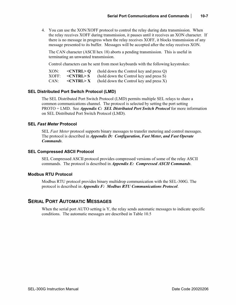
Serial Port Communications and Commands 10-7
SEL-300G Instruction Manual Date Code 20020206
4. You can use the XON/XOFF protocol to control the relay during data transmission. When the relay receives XOFF during transmission, it pauses until it receives an XON character. If there is no message in progress when the relay receives XOFF, it blocks transmission of any message presented to its buffer. Messages will be accepted after the relay receives XON.
The CAN character (ASCII hex 18) aborts a pending transmission. This is useful in terminating an unwanted transmission.
Control characters can be sent from most keyboards with the following keystrokes:
XON: <CNTRL> Q (hold down the Control key and press Q) XOFF: <CNTRL> S (hold down the Control key and press S) CAN: <CNTRL> X (hold down the Control key and press X)
SEL Distributed Port Switch Protocol (LMD) The SEL Distributed Port Switch Protocol (LMD) permits multiple SEL relays to share a common communications channel. The protocol is selected by setting the port setting PROTO = LMD. See Appendix C: SEL Distributed Port Switch Protocol for more information on SEL Distributed Port Switch Protocol (LMD).
SEL Fast Meter Protocol SEL Fast Meter protocol supports binary messages to transfer metering and control messages. The protocol is described in Appendix D: Configuration, Fast Meter, and Fast Operate Commands.
SEL Compressed ASCII Protocol SEL Compressed ASCII protocol provides compressed versions of some of the relay ASCII commands. The protocol is described in Appendix E: Compressed ASCII Commands.
Modbus RTU Protocol Modbus RTU protocol provides binary multidrop communication with the SEL-300G. The protocol is described in Appendix F: Modbus RTU Communications Protocol.
SERIAL PORT AUTOMATIC MESSAGES When the serial port AUTO setting is Y, the relay sends automatic messages to indicate specific conditions. The automatic messages are described in Table 10.5

10-8 Serial Port Communications and Commands
Date Code 20000616 SEL-300G Instruction Manual
Table 10.5: Serial Port Automatic Messages
Condition Description
Power Up The relay sends a message containing the present date and time, relay and terminal identifiers, and the Access Level 0 prompt when the relay is turned on.
Event Trigger The relay sends an event summary each time an event report is triggered. See Section 11: Event Reports and SER Functions.
Group Switch The relay displays the active settings group after a group switch occurs. See GRO n Command (Change Active Settings Group) in this section.
Self-Test Warning or Failure The relay sends a status report each time a self-test warning or failure condition is detected. See STA Command (Relay Self-Test Status) in this section.
SERIAL PORT ACCESS LEVELS Commands can be issued to the relay via the serial port to view metering values, change relay settings, etc. The available serial port commands are listed in Table 10.6. The commands can be accessed only from the corresponding access level as shown in Table 10.6. The access levels are:
Access Level 0 (the lowest access level) Access Level 1 Access Level B Access Level 2 (the highest access level)
Note: In this manual, commands you type appear in bold/uppercase: OTTER. Computer keys you press appear in bold/uppercase/brackets: <ENTER>.
Access Level 0 Once serial port communications are established with the relay, the relay sends the following prompt:
=
This is referred to as Access Level 0. The only commands available at Access Level 0 are the ACC HELP commands (see). Enter the ACC command at the Access Level 0 prompt:
=ACC <ENTER>
The ACC command takes the relay to Access Level 1 [see ACC, BAC, and 2AC Commands (Go to Access Level 1, B, or 2) in the Command Explanations subsection for more detail].
Access Level 1 When the relay is in Access Level 1, the relay sends the following prompt:
=>

Serial Port Communications and Commands 10-9
SEL-300G Instruction Manual Date Code 20000616
Commands ACC through TRI in Table 10.6 are available from Access Level 1. For example, enter the MET command at the Access Level 1 prompt to view metering data:
=>MET <ENTER>
The 2AC command allows the relay to go to Access Level 2 [see ACC, BAC, and 2AC Commands (Go to Access Level 1, B, or 2) in the Command Explanations subsection for more detail]. Enter the 2AC command at the Access Level 1 prompt:
=>2AC <ENTER>
The BAC command allows the relay to go to Access Level B [see ACC, BAC, and 2AC Commands (Go to Access Level 1, B, or 2) in the Command Explanations subsection for more detail]. Enter the BAC command at the Access Level 1 prompt:
=>BAC <ENTER>
Access Level B When the relay is in Access Level B, the relay sends the prompt:
= = >
Commands ACC through PUL in Table 10.6 are available from Access Level B. For example, enter the CLO command at the Access Level B prompt to close the circuit breaker:
==>CLO <ENTER>
The 2AC command allows the relay to go to Access Level 2 [see ACC, BAC, and 2AC Commands (Go to Access Level 1, B, or 2) in the Command Explanations subsection for more detail]. Enter the 2AC command at the Access Level B prompt:
==>2AC <ENTER>
Access Level 2 When the relay is in Access Level 2, the relay sends the prompt:
=>>
Commands ACC through STA C in Table 10.6 are available from Access Level 2. For example, enter the SET command at the Access Level 2 prompt to make relay settings:
=>>SET <ENTER>
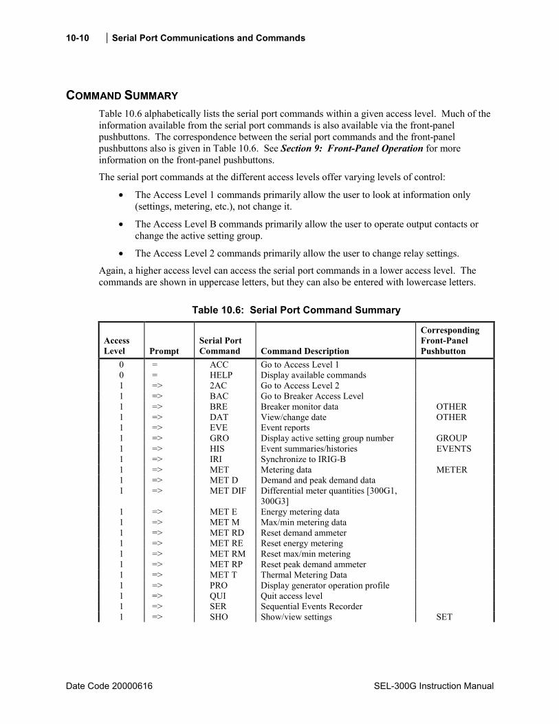
10-10 Serial Port Communications and Commands
Date Code 20000616 SEL-300G Instruction Manual
COMMAND SUMMARY Table 10.6 alphabetically lists the serial port commands within a given access level. Much of the information available from the serial port commands is also available via the front-panel pushbuttons. The correspondence between the serial port commands and the front-panel pushbuttons also is given in Table 10.6. See Section 9: Front-Panel Operation for more information on the front-panel pushbuttons.
The serial port commands at the different access levels offer varying levels of control:
• The Access Level 1 commands primarily allow the user to look at information only (settings, metering, etc.), not change it.
• The Access Level B commands primarily allow the user to operate output contacts or change the active setting group.
• The Access Level 2 commands primarily allow the user to change relay settings.
Again, a higher access level can access the serial port commands in a lower access level. The commands are shown in uppercase letters, but they can also be entered with lowercase letters.
Table 10.6: Serial Port Command Summary
Access Level Prompt
Serial Port Command Command Description
Corresponding Front-Panel Pushbutton
0 = ACC Go to Access Level 1 0 = HELP Display available commands 1 => 2AC Go to Access Level 2 1 => BAC Go to Breaker Access Level 1 => BRE Breaker monitor data OTHER 1 => DAT View/change date OTHER 1 => EVE Event reports 1 => GRO Display active setting group number GROUP 1 => HIS Event summaries/histories EVENTS 1 => IRI Synchronize to IRIG-B 1 => MET Metering data METER 1 => MET D Demand and peak demand data 1 => MET DIF Differential meter quantities [300G1,
300G3]
1 => MET E Energy metering data 1 => MET M Max/min metering data 1 => MET RD Reset demand ammeter 1 => MET RE Reset energy metering 1 => MET RM Reset max/min metering 1 => MET RP Reset peak demand ammeter 1 => MET T Thermal Metering Data 1 => PRO Display generator operation profile 1 => QUI Quit access level 1 => SER Sequential Events Recorder 1 => SHO Show/view settings SET
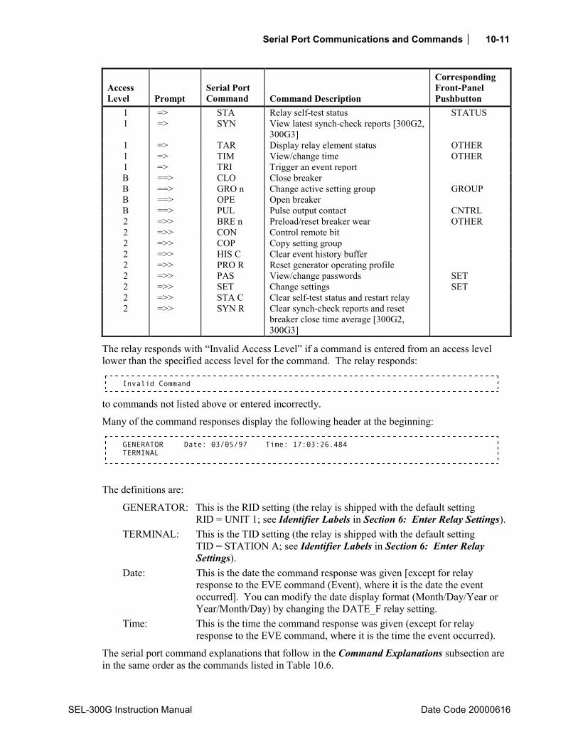
Serial Port Communications and Commands 10-11
SEL-300G Instruction Manual Date Code 20000616
Access Level Prompt
Serial Port Command Command Description
Corresponding Front-Panel Pushbutton
1 => STA Relay self-test status STATUS 1 => SYN View latest synch-check reports [300G2,
300G3]
1 => TAR Display relay element status OTHER 1 => TIM View/change time OTHER 1 => TRI Trigger an event report B ==> CLO Close breaker B ==> GRO n Change active setting group GROUP B ==> OPE Open breaker B ==> PUL Pulse output contact CNTRL 2 =>> BRE n Preload/reset breaker wear OTHER 2 =>> CON Control remote bit 2 =>> COP Copy setting group 2 =>> HIS C Clear event history buffer 2 =>> PRO R Reset generator operating profile 2 =>> PAS View/change passwords SET 2 =>> SET Change settings SET 2 =>> STA C Clear self-test status and restart relay 2 =>> SYN R Clear synch-check reports and reset
breaker close time average [300G2, 300G3]
The relay responds with Invalid Access Level if a command is entered from an access level lower than the specified access level for the command. The relay responds:
Invalid Command
to commands not listed above or entered incorrectly.
Many of the command responses display the following header at the beginning:
GENERATOR Date: 03/05/97 Time: 17:03:26.484 TERMINAL
The definitions are:
GENERATOR: This is the RID setting (the relay is shipped with the default setting RID = UNIT 1; see Identifier Labels in Section 6: Enter Relay Settings).
TERMINAL: This is the TID setting (the relay is shipped with the default setting TID = STATION A; see Identifier Labels in Section 6: Enter Relay Settings).
Date: This is the date the command response was given [except for relay response to the EVE command (Event), where it is the date the event occurred]. You can modify the date display format (Month/Day/Year or Year/Month/Day) by changing the DATE_F relay setting.
Time: This is the time the command response was given (except for relay response to the EVE command, where it is the time the event occurred).
The serial port command explanations that follow in the Command Explanations subsection are in the same order as the commands listed in Table 10.6.

10-12 Serial Port Communications and Commands
Date Code 20000616 SEL-300G Instruction Manual
COMMAND EXPLANATIONS
Access Level 0 Commands
HELP Command (Display Available Serial Port Commands) Use the HELP command to display the serial port commands available at each access level. The command displays only the available commands for the active access level.
For more details regarding a particular command, type HELP CMD, where CMD is the name of the command you are interested in.
ACC, BAC, and 2AC Commands (Go to Access Level 1, B, or 2) The ACC, BAC, and 2AC commands provide entry to the multiple access levels. Different commands are available at the different access levels as shown in Table 10.6. Commands ACC, BAC, and 2AC are explained together because they operate similarly.
ACC moves from Access Level 0 to Access Level 1. BAC moves from Access Level 1 to Access Level B. 2AC moves from Access Level 1 or B to Access Level 2.
Password Requirements and Default Passwords Passwords are required if the main board Password jumper is not in place (Password jumper = OFF). Passwords are not required if the main board Password jumper is in place (Password jumper = ON). Refer to Table 5.5 and Table 5.6 for Password jumper information. See PAS Command (View/Change Passwords) explanation later in this section for the list of default passwords and for more information on changing passwords.
Access Level Attempt (Password Required) Assume the following conditions: Password jumper = OFF (not in place), Access Level = 0.
At the Access Level 0 prompt, enter the ACC command:
=ACC <ENTER>
Because the Password jumper is not in place, the relay asks for the Access Level 1 password to be entered:
Password: ? @@@@@@
The relay is shipped with the default Access Level 1 password shown in the table under the PAS command later in this section. At the above prompt enter the default password and press the <enter> key.
The relay responds:
GENERATOR Date: 01/17/98 Time: 09:46:47.237 TERMINAL Level 1 =>
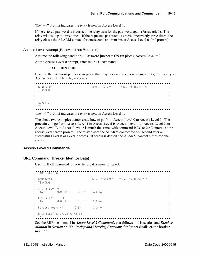
Serial Port Communications and Commands 10-13
SEL-300G Instruction Manual Date Code 20000616
The => prompt indicates the relay is now in Access Level 1.
If the entered password is incorrect, the relay asks for the password again (Password: ?). The relay will ask up to three times. If the requested password is entered incorrectly three times, the relay closes the ALARM contact for one second and remains at Access Level 0 (= prompt).
Access Level Attempt (Password not Required) Assume the following conditions: Password jumper = ON (in place), Access Level = 0.
At the Access Level 0 prompt, enter the ACC command:
=ACC <ENTER>
Because the Password jumper is in place, the relay does not ask for a password; it goes directly to Access Level 1. The relay responds:
GENERATOR Date: 01/17/98 Time: 09:46:47.237 TERMINAL Level 1 =>
The => prompt indicates the relay is now in Access Level 1.
The above two examples demonstrate how to go from Access Level 0 to Access Level 1. The procedure to go from Access Level 1 to Access Level B, Access Level 1 to Access Level 2, or Access Level B to Access Level 2 is much the same, with command BAC or 2AC entered at the access level screen prompt. The relay closes the ALARM contact for one second after a successful Level B or Level 2 access. If access is denied, the ALARM contact closes for one second.
Access Level 1 Commands
BRE Command (Breaker Monitor Data) Use the BRE command to view the breaker monitor report. =>BRE <ENTER> GENERATOR Date: 01/17/98 Time: 09:46:51.613 TERMINAL Int Trips= 0 IA= 0.0 IB= 0.0 IC= 0.0 kA Ext Trips= 0 IA= 0.0 IB= 0.0 IC= 0.0 kA Percent wear: A= 0 B= 0 C= 0 LAST RESET 01/17/98 09:45:35 =>
See the BRE n command in Access Level 2 Commands that follows in this section and Breaker Monitor in Section 8: Monitoring and Metering Functions for further details on the breaker monitor.

10-14 Serial Port Communications and Commands
Date Code 20000616 SEL-300G Instruction Manual
DAT Command (View/Change Date) DAT displays the date stored by the internal calendar/clock. If the date format setting DATE_F is set to MDY, the date is displayed as month/day/year. If the date format setting DATE_F is set to YMD, the date is displayed as year/month/day.
To set the date, type DATE mm/dd/yy <ENTER> if the DATE_F setting is MDY. If the DATE_F is set to YMD, enter DATE yy/mm/dd <ENTER>. To set the date to February 1, 1998, enter:
=>DATE 2/1/98 <ENTER> 2/1/98 =>
You can separate the month, day, and year parameters with spaces, commas, slashes, colons, and semicolons.
EVE Command (Event Reports) Use the EVE command to view event reports. See Section 11: Event Reports and SER Functions for further details on retrieving event reports.
GRO Command (Display Active Setting Group Number) Use the GRO command to display the active settings group number. See the GRO n Command (Change Active Setting Group) in Access Level B Commands that follows in this section and Section 3: Auxiliary Function Settings for further details on settings groups.
HIS Command (Event Summaries/History) HIS x displays event summaries or allows you to clear event summaries (and corresponding event reports) from nonvolatile memory.
If no parameters are specified with the HIS command:
=HIS <ENTER>
the relay displays the most recent event summaries in reverse chronological order.
If x is a number (1 - 16):
=HIS 6 <ENTER>
the relay displays the x most recent event summaries. The maximum number of available event summaries is a function of the LER (length of event report) setting. The relay saves up to twenty-nine 15-cycle event reports if setting LER = 15 and fifteen 30-cycle event reports if setting LER = 30.
The event summaries include the date and time the event was triggered, the type of event, the maximum phase current in the event, the power system frequency, the number of the active setting group, and the front-panel targets.

Serial Port Communications and Commands 10-15
SEL-300G Instruction Manual Date Code 20000616
To display the relay event summaries, enter the following command:
=>HIS <ENTER> GENERATOR Date: 01/21/98 Time: 14:51:21.370 TERMINAL # DATE TIME EVENT CURR FREQ GRP TARGETS 1 01/20/98 09:09:58.814 ER 4 60.01 2 2 01/20/98 09:09:58.615 TRIP 1470 60.16 2 50 N 27/59 3 01/20/98 09:09:55.614 ER 1008 60.01 2 =>
The event type listed in the EVENT column is one of the following:
TRIP: event report generated by assertion of Relay Word bit TRIP ER: event report generated by assertion of SELOGIC® Control Equation event report
trigger condition setting ER PULSE: event report generated by execution of the PUL (Pulse) command TRIG: event report generated by execution of the TRI (Trigger) command
The TARGETS column will display any of the following illuminated front-panel target LEDs if the event report is generated by a trip (assertion of a TRIPn Relay Word bit).
For more information on front-panel target LEDs, see Section 9: Front-Panel Operation. For more information on event reports, see Section 11: Event Reports and SER Functions.
IRI Command (Synchronize to IRIG-B Time Code) IRI directs the relay to read the demodulated IRIG-B time code at the serial port input.
To force the relay to synchronize to IRIG-B, enter the following command:
=>IRI <ENTER>
If the relay successfully synchronizes to IRIG-B, it sends the following header and access level prompt:
GENERATOR Date: 03/05/97 Time: 10:15:09.609 TERMINAL =>
If no IRIG-B code is present at the serial port input or if the code cannot be read successfully, the relay responds:
IRIG-B DATA ERROR =>
If an IRIG-B signal is present, the relay synchronizes its internal clock with IRIG-B. It is not necessary to issue the IRI command to synchronize the relay clock with IRIG-B. Use the IRI command to determine if the relay is properly reading the IRIG-B signal.
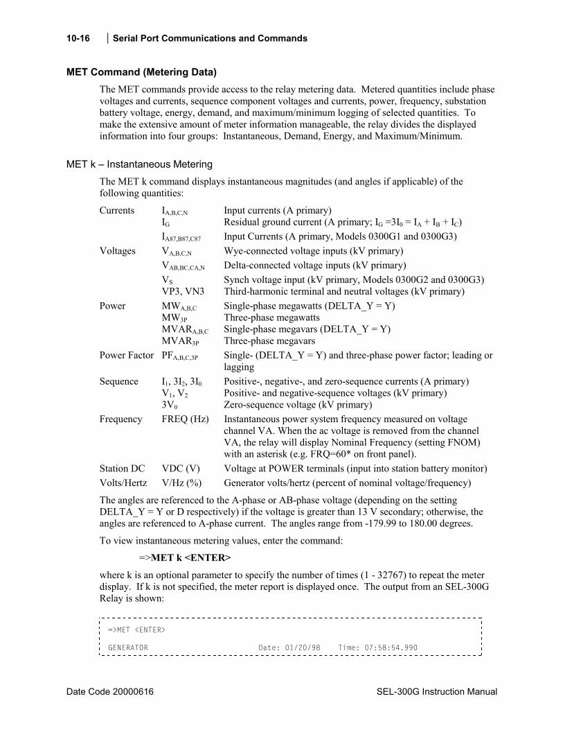
10-16 Serial Port Communications and Commands
Date Code 20000616 SEL-300G Instruction Manual
MET Command (Metering Data) The MET commands provide access to the relay metering data. Metered quantities include phase voltages and currents, sequence component voltages and currents, power, frequency, substation battery voltage, energy, demand, and maximum/minimum logging of selected quantities. To make the extensive amount of meter information manageable, the relay divides the displayed information into four groups: Instantaneous, Demand, Energy, and Maximum/Minimum.
MET k Instantaneous Metering The MET k command displays instantaneous magnitudes (and angles if applicable) of the following quantities:
Currents IA,B,C,N Input currents (A primary) IG Residual ground current (A primary; IG =3I0 = IA + IB + IC) IA87,B87,C87 Input Currents (A primary, Models 0300G1 and 0300G3) Voltages VA,B,C,N Wye-connected voltage inputs (kV primary) VAB,BC,CA,N Delta-connected voltage inputs (kV primary) VS Synch voltage input (kV primary, Models 0300G2 and 0300G3) VP3, VN3 Third-harmonic terminal and neutral voltages (kV primary) Power MWA,B,C Single-phase megawatts (DELTA_Y = Y) MW3P Three-phase megawatts MVARA,B,C Single-phase megavars (DELTA_Y = Y) MVAR3P Three-phase megavars Power Factor PFA,B,C,3P Single- (DELTA_Y = Y) and three-phase power factor; leading or lagging Sequence I1, 3I2, 3I0 Positive-, negative-, and zero-sequence currents (A primary) V1, V2 Positive- and negative-sequence voltages (kV primary) 3V0 Zero-sequence voltage (kV primary) Frequency FREQ (Hz) Instantaneous power system frequency measured on voltage
channel VA. When the ac voltage is removed from the channel VA, the relay will display Nominal Frequency (setting FNOM) with an asterisk (e.g. FRQ=60* on front panel).
Station DC VDC (V) Voltage at POWER terminals (input into station battery monitor) Volts/Hertz V/Hz (%) Generator volts/hertz (percent of nominal voltage/frequency)
The angles are referenced to the A-phase or AB-phase voltage (depending on the setting DELTA_Y = Y or D respectively) if the voltage is greater than 13 V secondary; otherwise, the angles are referenced to A-phase current. The angles range from -179.99 to 180.00 degrees.
To view instantaneous metering values, enter the command:
=>MET k <ENTER>
where k is an optional parameter to specify the number of times (1 - 32767) to repeat the meter display. If k is not specified, the meter report is displayed once. The output from an SEL-300G Relay is shown:
=>MET <ENTER> GENERATOR Date: 01/20/98 Time: 07:58:54.990

Serial Port Communications and Commands 10-17
SEL-300G Instruction Manual Date Code 20000616
TERMINAL A B C N G I MAG (A) 904.052 903.011 908.535 0.034 4.286 I ANG (DEG) -4.96 -124.88 115.02 56.40 90.93 A B C N V MAG (KV) 7.910 7.905 7.917 0.000 V ANG (DEG) 0.00 -119.89 120.09 8.22 VP3 VN3 V MAG (KV) 0.003 0.001 A B C 3P MW 7.125 7.111 7.165 21.401 MVAR 0.619 0.622 0.635 1.875 PF 0.996 0.996 0.996 0.996 LAG LAG LAG LAG I1 3I2 3I0 V1 V2 3V0 MAG 905.199 6.096 4.286 7.911 0.008 0.004 ANG (DEG) -4.94 -124.45 90.93 0.07 -99.02 -48.37 FREQ (Hz) 60.01 VDC (V) 122.5 V/Hz (percent) 99.60 =>
MET D Demand Metering The MET D command displays the demand and peak demand values of the following quantities:
Currents IA,B,C,N IG 3I2
Input currents (A primary) Residual ground current (A primary; IG =3I0 = IA + IB + IC) Negative-sequence current (A primary)
Power MWA,B,C MW3P MVARA,B,C MVAR3P
Single-phase megawatts (DELTA_Y = Y) Three-phase megawatts Single-phase megavars (DELTA_Y = Y) Three-phase megavars
Reset Time Demand, Peak Last time the demands and peak demands were reset
To view demand metering values, enter the command:
=>MET D <ENTER>
The output from an SEL-300G Relay is shown:
=>MET D <ENTER> GENERATOR Date: 01/20/98 Time: 07:59:03.241 TERMINAL IA IB IC IN IG 3I2 DEMAND 948.3 949.7 952.4 0.0 4.7 4.0 PEAK 964.0 965.4 968.1 0.7 9.2 4.3 MWA MWB MWC MW3P MVARA MVARB MVARC MVAR3P DEMAND IN 0.0 0.0 0.0 0.0 0.1 0.1 0.1 0.3 PEAK IN 0.0 0.0 0.0 0.0 0.1 0.1 0.1 0.4 DEMAND OUT 7.5 7.5 7.5 22.5 0.4 0.4 0.4 1.1 PEAK OUT 7.6 7.6 7.6 22.9 0.4 0.4 0.4 1.1
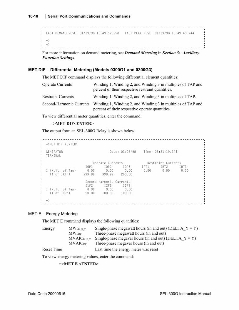
10-18 Serial Port Communications and Commands
Date Code 20000616 SEL-300G Instruction Manual
LAST DEMAND RESET 01/19/98 16:49:52.998 LAST PEAK RESET 01/19/98 16:49:48.744 => =>
For more information on demand metering, see Demand Metering in Section 3: Auxiliary Function Settings.
MET DIF Differential Metering (Models 0300G1 and 0300G3) The MET DIF command displays the following differential element quantities:
Operate Currents Winding 1, Winding 2, and Winding 3 in multiples of TAP and percent of their respective restraint quantities.
Restraint Currents Winding 1, Winding 2, and Winding 3 in multiples of TAP.
Second-Harmonic Currents Winding 1, Winding 2, and Winding 3 in multiples of TAP and percent of their respective operate quantities.
To view differential meter quantities, enter the command:
=>MET DIF<ENTER>
The output from an SEL-300G Relay is shown below:
=>MET Dif <ENTER> GENERATOR Date: 03/06/98 Time: 08:21:19.744 TERMINAL Operate Currents Restraint Currents IOP1 IOP2 IOP3 IRT1 IRT2 IRT3 I (Mult. of Tap) 0.00 0.00 0.00 0.00 0.00 0.00 (% of IRTn) 999.99 999.99 200.00 Second Harmonic Currents I1F2 I2F2 I3F2 I (Mult. of Tap) 0.00 0.00 0.00 (% of IOPn) 50.00 100.00 100.00 =>
MET E Energy Metering The MET E command displays the following quantities:
Energy MWhA,B,C Single-phase megawatt hours (in and out) (DELTA_Y = Y) MWh3P Three-phase megawatt hours (in and out) MVARhA,B,C Single-phase megavar hours (in and out) (DELTA_Y = Y) MVARh3P Three-phase megavar hours (in and out) Reset Time Last time the energy meter was reset
To view energy metering values, enter the command:
=>MET E <ENTER>
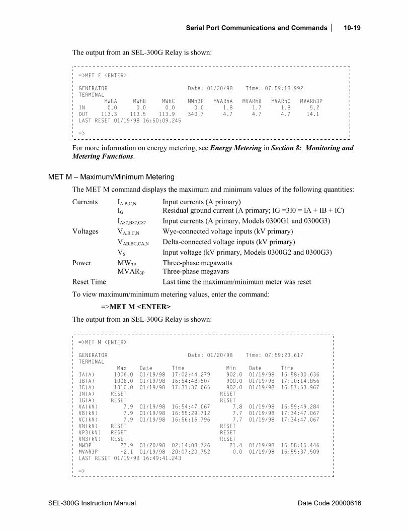
Serial Port Communications and Commands 10-19
SEL-300G Instruction Manual Date Code 20000616
The output from an SEL-300G Relay is shown:
=>MET E <ENTER> GENERATOR Date: 01/20/98 Time: 07:59:18.992 TERMINAL MWhA MWhB MWhC MWh3P MVARhA MVARhB MVARhC MVARh3P IN 0.0 0.0 0.0 0.0 1.8 1.7 1.8 5.2 OUT 113.3 113.5 113.9 340.7 4.7 4.7 4.7 14.1 LAST RESET 01/19/98 16:50:09.245 =>
For more information on energy metering, see Energy Metering in Section 8: Monitoring and Metering Functions.
MET M Maximum/Minimum Metering The MET M command displays the maximum and minimum values of the following quantities:
Currents IA,B,C,N Input currents (A primary) IG Residual ground current (A primary; IG =3I0 = IA + IB + IC) IA87,B87,C87 Input currents (A primary, Models 0300G1 and 0300G3) Voltages VA,B,C,N Wye-connected voltage inputs (kV primary) VAB,BC,CA,N Delta-connected voltage inputs (kV primary) VS Input voltage (kV primary, Models 0300G2 and 0300G3) Power MW3P Three-phase megawatts MVAR3P Three-phase megavars Reset Time Last time the maximum/minimum meter was reset
To view maximum/minimum metering values, enter the command:
=>MET M <ENTER>
The output from an SEL-300G Relay is shown:
=>MET M <ENTER> GENERATOR Date: 01/20/98 Time: 07:59:23.617 TERMINAL Max Date Time Min Date Time IA(A) 1006.0 01/19/98 17:02:44.279 902.0 01/19/98 16:58:30.636 IB(A) 1006.0 01/19/98 16:54:48.507 900.0 01/19/98 17:10:14.856 IC(A) 1010.0 01/19/98 17:31:37.065 902.0 01/19/98 16:57:53.967 IN(A) RESET RESET IG(A) RESET RESET VA(kV) 7.9 01/19/98 16:54:47.067 7.8 01/19/98 16:59:49.284 VB(kV) 7.9 01/19/98 16:55:29.712 7.7 01/19/98 17:34:47.067 VC(kV) 7.9 01/19/98 16:56:16.796 7.7 01/19/98 17:34:47.067 VN(kV) RESET RESET VP3(kV) RESET RESET VN3(kV) RESET RESET MW3P 23.9 01/20/98 02:14:08.726 21.4 01/19/98 16:58:15.446 MVAR3P -2.1 01/19/98 20:07:20.752 0.0 01/19/98 16:55:37.509 LAST RESET 01/19/98 16:49:41.243 =>
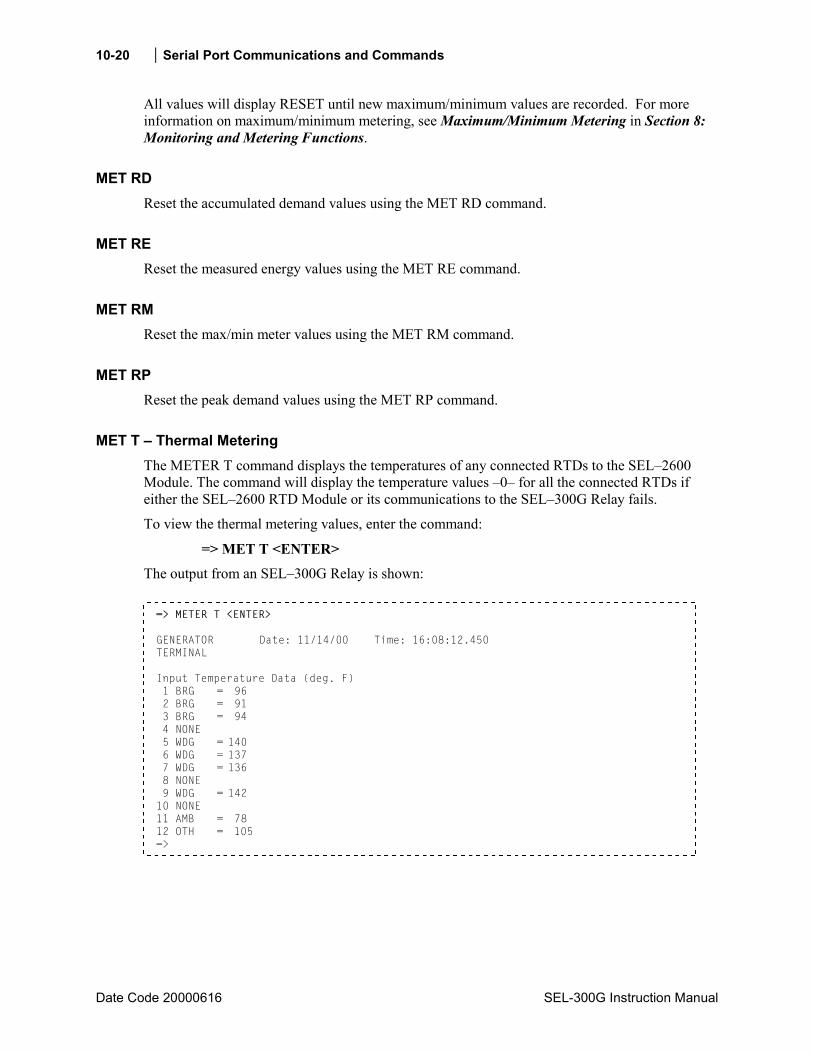
10-20 Serial Port Communications and Commands
Date Code 20000616 SEL-300G Instruction Manual
All values will display RESET until new maximum/minimum values are recorded. For more information on maximum/minimum metering, see Maximum/Minimum Metering in Section 8: Monitoring and Metering Functions.
MET RD Reset the accumulated demand values using the MET RD command.
MET RE Reset the measured energy values using the MET RE command.
MET RM Reset the max/min meter values using the MET RM command.
MET RP Reset the peak demand values using the MET RP command.
MET T Thermal Metering The METER T command displays the temperatures of any connected RTDs to the SEL2600 Module. The command will display the temperature values 0 for all the connected RTDs if either the SEL2600 RTD Module or its communications to the SEL300G Relay fails.
To view the thermal metering values, enter the command:
=> MET T <ENTER> The output from an SEL300G Relay is shown:
=> METER T <ENTER> GENERATOR Date: 11/14/00 Time: 16:08:12.450 TERMINAL Input Temperature Data (deg. F) 1 BRG = 96 2 BRG = 91 3 BRG = 94 4 NONE 5 WDG = 140 6 WDG = 137 7 WDG = 136 8 NONE 9 WDG = 142 10 NONE 11 AMB = 78 12 OTH = 105 =>

Serial Port Communications and Commands 10-21
SEL-300G Instruction Manual Date Code 20000616
PRO Command (Display Generator Operation Profile) The PRO command displays the generator operation profile which includes:
• Present accumulated time in 81AC Off-Frequency Time Accumulators, if enabled
• Total generator running hours, stopped hours, full load hours, and percent running time
• Accumulated I22t
• Three-phase power output averages
• Generator time of operation in 0.1 Hz frequency bands from 40.0 to 69.9 Hz
To view the generator operation profile, enter the command:
=>PRO <ENTER>

10-22 Serial Port Communications and Commands
Date Code 20000616 SEL-300G Instruction Manual
The output from an SEL-300G Relay is shown:
=>PRO <ENTER> GENERATOR Date: 01/17/98 Time: 09:47:45.114 TERMINAL 81AC Off-Frequency Time Accumulators Since: 01/17/98 09:46 Frequency Band 1, 59.5 to 58.8: 0.0s or 0.0% of limit setting Frequency Band 2, 58.8 to 58.0: 0.0s or 0.0% of limit setting Frequency Band 3, 58.0 to 57.5: 0.0s or 0.0% of limit setting Frequency Band 4, 57.5 to 57.0: 0.0s or 0.0% of limit setting Frequency Band 5, 57.0 to 56.5: 0.0s or 0.0% of limit setting Frequency Band 6, 56.5 to 40.0: 0.0s or 0.0% of limit setting Operating History, elapsed time in dd:hh:mm:ss Since: 01/17/98 09:46 Running hours: 0:00:00:00 Stopped hours: > 0:00:01:18 Full load hours: 0:00:00:00 Time running: 0.0% Accumulated I2*I2*t (A*A*s): 0.0 Average power Since: 01/17/98 09:46 MW out: 0.00 MVAR out: 0.00 MVAR in: 0.00 Power factor: 0.00 LEAD Press RETURN to continue Operating Freq (Hz), elapsed time in dd:hh:mm:ss Since: 01/17/98 09:46 40.0 40.1 40.2 40.3 40.4 0:00:00:00 0:00:00:00 0:00:00:00 0:00:00:00 0:00:00:00 40.5 40.6 40.7 40.8 40.9 0:00:00:00 0:00:00:00 0:00:00:00 0:00:00:00 0:00:00:00 . . . 67.5 67.6 67.7 67.8 67.9 0:00:00:00 0:00:00:00 0:00:00:00 0:00:00:00 0:00:00:00 68.0 68.1 68.2 68.3 68.4 0:00:00:00 0:00:00:00 0:00:00:00 0:00:00:00 0:00:00:00 68.5 68.6 68.7 68.8 68.9 0:00:00:00 0:00:00:00 0:00:00:00 0:00:00:00 0:00:00:00 69.0 69.1 69.2 69.3 69.4 0:00:00:00 0:00:00:00 0:00:00:00 0:00:00:00 0:00:00:00 69.5 69.6 69.7 69.8 69.9 0:00:00:00 0:00:00:00 0:00:00:00 0:00:00:00 0:00:56:56 =>
Section 8: Monitoring and Metering Functions provides additional information on the SEL-300G Relay generator operating profile function.
QUI Command (Quit Access Level) The QUI command returns the relay to Access Level 0.
To return to Access Level 0, enter the command:
=>QUI <ENTER>

Serial Port Communications and Commands 10-23
SEL-300G Instruction Manual Date Code 20000616
The relay sets the port access level to 0 and responds:
GENERATOR Date: 03/05/97 Time: 08:55:33.986 TERMINAL =
The = prompt indicates the relay is back in Access Level 0.
The QUI command terminates the SEL Distributed Port Switch Protocol (LMD) connection if it is established (see Appendix C: SEL Distributed Port Switch Protocl for details on SEL Distributed Port Switch Protocol [LMD]).
SER Command (Sequential Events Recorder Report) Use the SER command to view the Sequential Events Recorder (SER) report. For more information on SER reports, see Section 11: Event Reports and SER Functions.
SHO Command (Show/View Settings) Use the SHO command to view relay settings, SELOGIC Control Equations, global settings, serial port settings, SER settings, and text label settings. Below are the SHO command options.
SHO n Show relay settings. n specifies the setting group (1 or 2); n defaults to the active setting group if not listed.
SHO G Show global settings. SHO P n Show serial port settings. n specifies the port (1, 2, 3, or
F); n defaults to the active port if not listed. SHO R Show SER settings.
You may append a setting name to each of the commands to specify the first setting to display (e.g., SHO 1 E50P displays the setting Group 1 relay settings starting with setting E50P). The default is the first setting.
The SHO commands display only the enabled settings. To display all settings, including disabled/hidden settings, append an A to the SHO command (e.g., SHO 1 A).
Below are sample SHOWSET commands for the SEL-300G Relay model 0300G10, showing all the setting categories. The settings for the other SEL-300G Relay models are similar.
=>SHO Group 1 RID =GENERATOR TID =TERMINAL CTR = 100 CTRD = 100 CTRN = 100 PTR = 100 PTRN = 100 VNOM = 115.0 INOM = 5.0 EBUP = D E24 = Y E27 = Y E32 = Y E40 = Y E46 = Y E50 = Y E50_87 = N E51 = Y E59 = N E64 = Y E78 = 1B E81 = 1 E81AC = 6 E87 = G ESV = 6 ESL = 5 EDEM = ROL
(continued on next page)
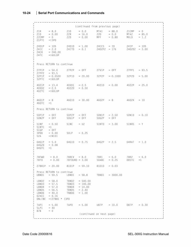
10-24 Serial Port Communications and Commands
Date Code 20000616 SEL-300G Instruction Manual
(continued from previous page)
Z1R = 8.0 Z1O = 0.0 MTA1 = 88.0 Z1CMP = 0 Z1D = 0.00 Z2R = 16.0 Z2O = 0.0 MTA2 = 85.0 Z2CMP = 0 Z2D = 0.00 MPF = 0.80 MXLD = 1.2 21PTC =!3PO 24D1P = 105 24D1D = 1.00 24CCS = ID 24IP = 105 24IC = 2.0 24ITD = 0.1 24D2P2 = 176 24D2D2 = 3.00 24CR = 240.00 24TC =!60LOP Press RETURN to continue 27P1P = 54.0 27P2P = OFF 27V1P = OFF 27PP1 = 93.5 27PP2 = 93.5 32P1P =-0.0500 32P1D = 20.00 32P2P =-0.1000 32P2D = 5.00 32PTC =!60LOP 40Z1P = 13.4 40XD1 =-2.5 40Z1D = 0.00 40Z2P = 25.0 40XD2 =-2.5 40Z2D = 0.50 40ZTC =!60LOP 46Q1P = 8 46Q1D = 30.00 46Q2P = 8 46Q2K = 10 46QTC =1 Press RETURN to continue 50P1P = OFF 50P2P = OFF 50N1P = 2.50 50N1D = 0.10 50N2P = OFF 50G1P = OFF 50G2P = OFF 51NP = 0.50 51NC = U2 51NTD = 3.00 51NRS = Y 51NTC =1 51GP = OFF 3POD = 0.00 50LP = 0.25 52A =IN101 64G1P = 5.0 64G1D = 0.75 64G2P = 2.5 64RAT = 1.0 64G2D = 0.08 64GTC =1 78FWD = 8.0 78REV = 8.0 78R1 = 6.0 78R2 = 6.0 78TD = 0.00 78TDURD = 3.00 50ABC = 0.25 OOSTC =1 27B81P = 20.00 81D1P = 59.10 81D1D = 0.03 Press RETURN to continue UBND1 = 59.5 LBND1 = 58.8 TBND1 = 3000.00 LBND2 = 58.0 TBND2 = 540.00 LBND3 = 57.5 TBND3 = 100.00 LBND4 = 57.0 TBND4 = 14.00 LBND5 = 56.5 TBND5 = 2.40 LBND6 = 40.0 TNBD6 = 1.00 62ACC = 0.16 ONLINE =!27B81 * !3PO TAP1 = 5.00 TAPD = 5.00 U87P = 10.0 O87P = 0.30 SLP1 = 40 87B = 0
(continued on next page)
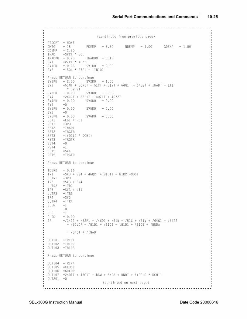
Serial Port Communications and Commands 10-25
SEL-300G Instruction Manual Date Code 20000616
(continued from previous page)
RTDOPT = NONE DMTC = 15 PDEMP = 5.50 NDEMP = 1.00 GDEMP = 1.00 QDEMP = 2.50 INAD =SV2T * 50L INADPU = 0.25 INADDO = 0.13 SV1 =27V1 * 40Z2 SV1PU = 0.25 SV1DO = 0.00 SV2 =!50L * 27P1 * !IN102 Press RETURN to continue SV2PU = 2.00 SV2DO = 1.00 SV3 =51NT + 50N1T + 51CT + 51VT + 64G1T + 64G2T + INADT + LT1 * 32P2T SV3PU = 0.00 SV3DO = 0.00 SV4 =24C2T + 32P1T + 40Z1T + 40Z2T SV4PU = 0.00 SV4DO = 0.00 SV5 =0 SV5PU = 0.00 SV5DO = 0.00 SV6 =0 SV6PU = 0.00 SV6DO = 0.00 SET1 =LB1 + RB1 RST1 =3PO SET2 =INADT RST2 =TRGTR SET3 =!(DCLO * DCHI) RST3 =TRGTR SET4 =0 RST4 =1 SET5 =SV4 RST5 =TRGTR Press RETURN to continue TDURD = 0.16 TR1 =SV3 + SV4 + 46Q2T + 81D1T + 81D2T+OOST ULTR1 =3PO TR2 =SV3 + SV4 ULTR2 =!TR2 TR3 =SV3 + LT1 ULTR3 =!TR3 TR4 =SV3 ULTR4 =!TR4 CLEN =1 CL =0 ULCL =1 CLSD = 0.00 ER =/24C2 + /32P1 + /46Q2 + /51N + /51C + /51V + /64G1 + /64G2 + /60LOP + /81D1 + /81D2 + \81D1 + \81D2 + /BNDA + /BNDT + /INAD OUT101 =TRIP1 OUT102 =TRIP2 OUT103 =TRIP3 Press RETURN to continue OUT104 =TRIP4 OUT105 =CLOSE OUT106 =60LOP OUT107 =24D1T + 46Q1T + BCW + BNDA + BNDT + !(DCLO * DCHI) OUT201 =0
(continued on next page)
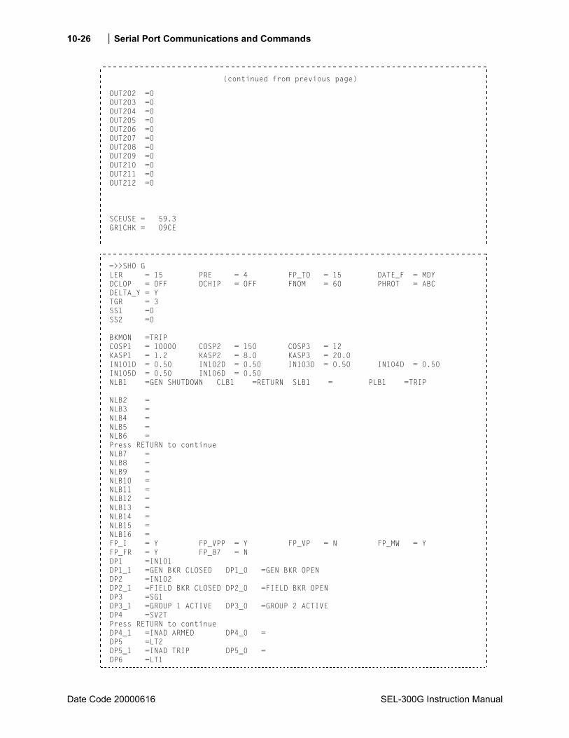
10-26 Serial Port Communications and Commands
Date Code 20000616 SEL-300G Instruction Manual
(continued from previous page)
OUT202 =0 OUT203 =0 OUT204 =0 OUT205 =0 OUT206 =0 OUT207 =0 OUT208 =0 OUT209 =0 OUT210 =0 OUT211 =0 OUT212 =0 SCEUSE = 59.3 GR1CHK = 09CE
=>>SHO G LER = 15 PRE = 4 FP_TO = 15 DATE_F = MDY DCLOP = OFF DCHIP = OFF FNOM = 60 PHROT = ABC DELTA_Y = Y TGR = 3 SS1 =0 SS2 =0 BKMON =TRIP COSP1 = 10000 COSP2 = 150 COSP3 = 12 KASP1 = 1.2 KASP2 = 8.0 KASP3 = 20.0 IN101D = 0.50 IN102D = 0.50 IN103D = 0.50 IN104D = 0.50 IN105D = 0.50 IN106D = 0.50 NLB1 =GEN SHUTDOWN CLB1 =RETURN SLB1 = PLB1 =TRIP NLB2 = NLB3 = NLB4 = NLB5 = NLB6 = Press RETURN to continue NLB7 = NLB8 = NLB9 = NLB10 = NLB11 = NLB12 = NLB13 = NLB14 = NLB15 = NLB16 = FP_I = Y FP_VPP = Y FP_VP = N FP_MW = Y FP_FR = Y FP_87 = N DP1 =IN101 DP1_1 =GEN BKR CLOSED DP1_0 =GEN BKR OPEN DP2 =IN102 DP2_1 =FIELD BKR CLOSED DP2_0 =FIELD BKR OPEN DP3 =SG1 DP3_1 =GROUP 1 ACTIVE DP3_0 =GROUP 2 ACTIVE DP4 =SV2T Press RETURN to continue DP4_1 =INAD ARMED DP4_0 = DP5 =LT2 DP5_1 =INAD TRIP DP5_0 = DP6 =LT1
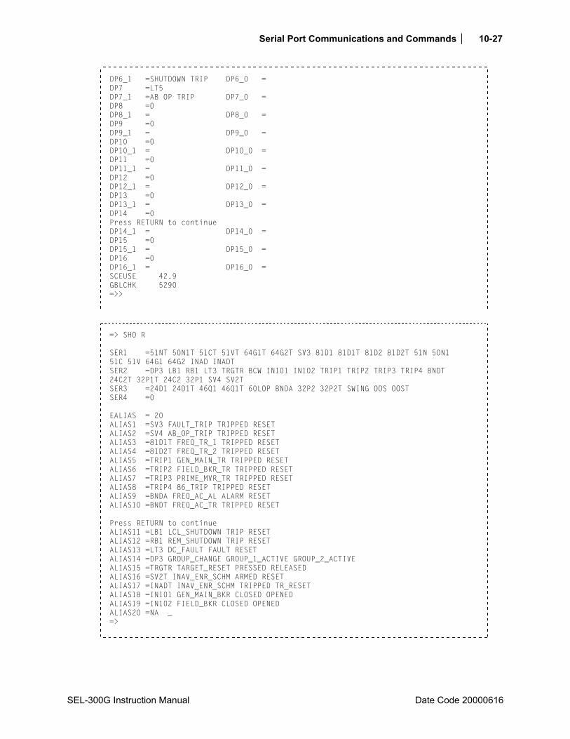
Serial Port Communications and Commands 10-27
SEL-300G Instruction Manual Date Code 20000616
DP6_1 =SHUTDOWN TRIP DP6_0 = DP7 =LT5 DP7_1 =AB OP TRIP DP7_0 = DP8 =0 DP8_1 = DP8_0 = DP9 =0 DP9_1 = DP9_0 = DP10 =0 DP10_1 = DP10_0 = DP11 =0 DP11_1 = DP11_0 = DP12 =0 DP12_1 = DP12_0 = DP13 =0 DP13_1 = DP13_0 = DP14 =0 Press RETURN to continue DP14_1 = DP14_0 = DP15 =0 DP15_1 = DP15_0 = DP16 =0 DP16_1 = DP16_0 = SCEUSE 42.9 GBLCHK 5290 =>>
=> SHO R SER1 =51NT 50N1T 51CT 51VT 64G1T 64G2T SV3 81D1 81D1T 81D2 81D2T 51N 50N1 51C 51V 64G1 64G2 INAD INADT SER2 =DP3 LB1 RB1 LT3 TRGTR BCW IN101 IN102 TRIP1 TRIP2 TRIP3 TRIP4 BNDT 24C2T 32P1T 24C2 32P1 SV4 SV2T SER3 =24D1 24D1T 46Q1 46Q1T 60LOP BNDA 32P2 32P2T SWING OOS OOST SER4 =0 EALIAS = 20 ALIAS1 =SV3 FAULT_TRIP TRIPPED RESET ALIAS2 =SV4 AB_OP_TRIP TRIPPED RESET ALIAS3 =81D1T FREQ_TR_1 TRIPPED RESET ALIAS4 =81D2T FREQ_TR_2 TRIPPED RESET ALIAS5 =TRIP1 GEN_MAIN_TR TRIPPED RESET ALIAS6 =TRIP2 FIELD_BKR_TR TRIPPED RESET ALIAS7 =TRIP3 PRIME_MVR_TR TRIPPED RESET ALIAS8 =TRIP4 86_TRIP TRIPPED RESET ALIAS9 =BNDA FREQ_AC_AL ALARM RESET ALIAS10 =BNDT FREQ_AC_TR TRIPPED RESET Press RETURN to continue ALIAS11 =LB1 LCL_SHUTDOWN TRIP RESET ALIAS12 =RB1 REM_SHUTDOWN TRIP RESET ALIAS13 =LT3 DC_FAULT FAULT RESET ALIAS14 =DP3 GROUP_CHANGE GROUP_1_ACTIVE GROUP_2_ACTIVE ALIAS15 =TRGTR TARGET_RESET PRESSED RELEASED ALIAS16 =SV2T INAV_ENR_SCHM ARMED RESET ALIAS17 =INADT INAV_ENR_SCHM TRIPPED TR_RESET ALIAS18 =IN101 GEN_MAIN_BKR CLOSED OPENED ALIAS19 =IN102 FIELD_BKR CLOSED OPENED ALIAS20 =NA _ =>
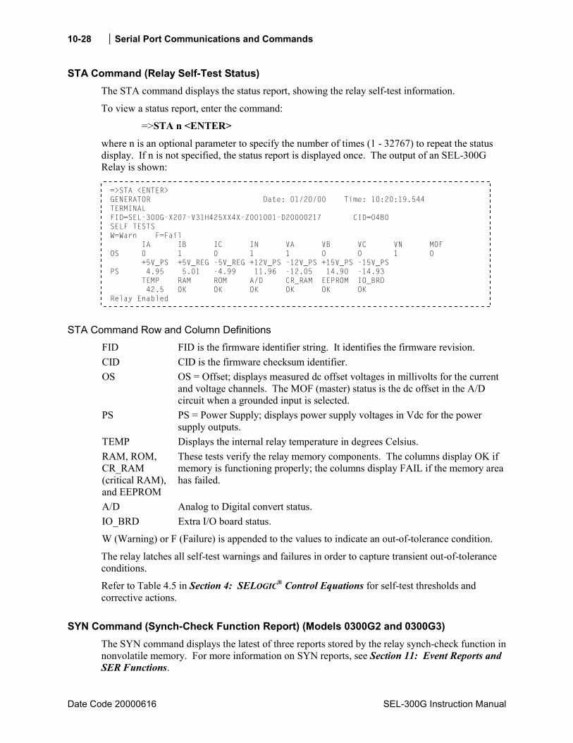
10-28 Serial Port Communications and Commands
Date Code 20000616 SEL-300G Instruction Manual
STA Command (Relay Self-Test Status) The STA command displays the status report, showing the relay self-test information.
To view a status report, enter the command:
=>STA n <ENTER>
where n is an optional parameter to specify the number of times (1 - 32767) to repeat the status display. If n is not specified, the status report is displayed once. The output of an SEL-300G Relay is shown:
=>STA <ENTER> GENERATOR Date: 01/20/00 Time: 10:20:19.544 TERMINAL FID=SEL-300G-X207-V31H425XX4X-Z001001-D20000217 CID=04B0 SELF TESTS W=Warn F=Fail IA IB IC IN VA VB VC VN MOF OS 0 1 0 1 1 0 0 1 0 +5V_PS +5V_REG -5V_REG +12V_PS -12V_PS +15V_PS -15V_PS PS 4.95 5.01 -4.99 11.96 -12.05 14.90 -14.93 TEMP RAM ROM A/D CR_RAM EEPROM IO_BRD 42.5 OK OK OK OK OK OK Relay Enabled
STA Command Row and Column Definitions FID FID is the firmware identifier string. It identifies the firmware revision. CID CID is the firmware checksum identifier. OS OS = Offset; displays measured dc offset voltages in millivolts for the current
and voltage channels. The MOF (master) status is the dc offset in the A/D circuit when a grounded input is selected.
PS PS = Power Supply; displays power supply voltages in Vdc for the power supply outputs.
TEMP Displays the internal relay temperature in degrees Celsius. RAM, ROM, CR_RAM (critical RAM), and EEPROM
These tests verify the relay memory components. The columns display OK if memory is functioning properly; the columns display FAIL if the memory area has failed.
A/D Analog to Digital convert status. IO_BRD Extra I/O board status.
W (Warning) or F (Failure) is appended to the values to indicate an out-of-tolerance condition.
The relay latches all self-test warnings and failures in order to capture transient out-of-tolerance conditions.
Refer to Table 4.5 in Section 4: SELOGIC® Control Equations for self-test thresholds and corrective actions.
SYN Command (Synch-Check Function Report) (Models 0300G2 and 0300G3) The SYN command displays the latest of three reports stored by the relay synch-check function in nonvolatile memory. For more information on SYN reports, see Section 11: Event Reports and SER Functions.
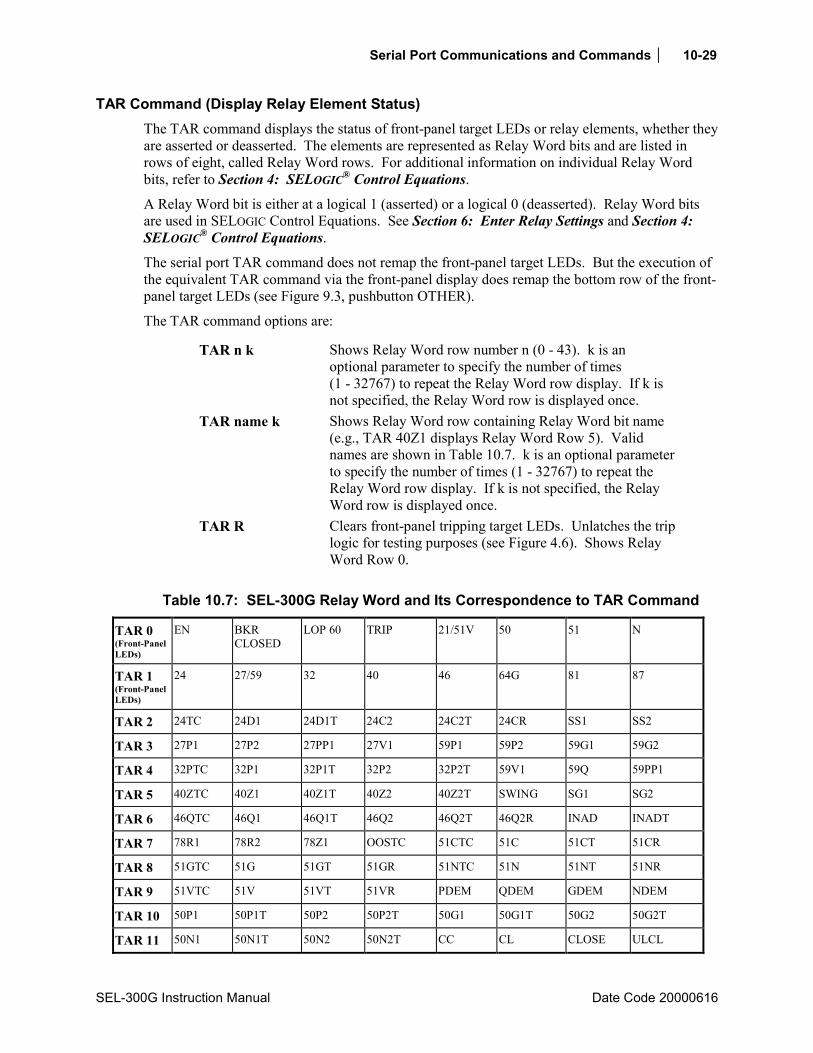
Serial Port Communications and Commands 10-29
SEL-300G Instruction Manual Date Code 20000616
TAR Command (Display Relay Element Status) The TAR command displays the status of front-panel target LEDs or relay elements, whether they are asserted or deasserted. The elements are represented as Relay Word bits and are listed in rows of eight, called Relay Word rows. For additional information on individual Relay Word bits, refer to Section 4: SELOGIC® Control Equations.
A Relay Word bit is either at a logical 1 (asserted) or a logical 0 (deasserted). Relay Word bits are used in SELOGIC Control Equations. See Section 6: Enter Relay Settings and Section 4: SELOGIC® Control Equations.
The serial port TAR command does not remap the front-panel target LEDs. But the execution of the equivalent TAR command via the front-panel display does remap the bottom row of the front-panel target LEDs (see Figure 9.3, pushbutton OTHER).
The TAR command options are:
TAR n k Shows Relay Word row number n (0 - 43). k is an optional parameter to specify the number of times (1 - 32767) to repeat the Relay Word row display. If k is not specified, the Relay Word row is displayed once.
TAR name k Shows Relay Word row containing Relay Word bit name (e.g., TAR 40Z1 displays Relay Word Row 5). Valid names are shown in Table 10.7. k is an optional parameter to specify the number of times (1 - 32767) to repeat the Relay Word row display. If k is not specified, the Relay Word row is displayed once.
TAR R Clears front-panel tripping target LEDs. Unlatches the trip logic for testing purposes (see Figure 4.6). Shows Relay Word Row 0.
Table 10.7: SEL-300G Relay Word and Its Correspondence to TAR Command
TAR 0 (Front-Panel LEDs)
EN BKR CLOSED
LOP 60 TRIP 21/51V 50 51 N
TAR 1 (Front-Panel LEDs)
24 27/59 32 40 46 64G 81 87
TAR 2 24TC 24D1 24D1T 24C2 24C2T 24CR SS1 SS2
TAR 3 27P1 27P2 27PP1 27V1 59P1 59P2 59G1 59G2
TAR 4 32PTC 32P1 32P1T 32P2 32P2T 59V1 59Q 59PP1
TAR 5 40ZTC 40Z1 40Z1T 40Z2 40Z2T SWING SG1 SG2
TAR 6 46QTC 46Q1 46Q1T 46Q2 46Q2T 46Q2R INAD INADT
TAR 7 78R1 78R2 78Z1 OOSTC 51CTC 51C 51CT 51CR
TAR 8 51GTC 51G 51GT 51GR 51NTC 51N 51NT 51NR
TAR 9 51VTC 51V 51VT 51VR PDEM QDEM GDEM NDEM
TAR 10 50P1 50P1T 50P2 50P2T 50G1 50G1T 50G2 50G2T
TAR 11 50N1 50N1T 50N2 50N2T CC CL CLOSE ULCL

10-30 Serial Port Communications and Commands
Date Code 20000616 SEL-300G Instruction Manual
TAR 12 64GTC 64G1 64G1T 64G2 64G2T OOS 60LOP CLEN
TAR 13 BKMON BCW BCWA BCWB BCWC FAULT DCLO DCHI
TAR 14 81D1 81D2 81D3 81D4 81D5 81D6 3PO 52A
TAR 15 81D1T 81D2T 81D3T 81D4T 81D5T 81D6T 27B81 50L
TAR 16 ONLINE BND1A BND1T BND2A BND2T BND3A BND3T BNDA
TAR 17 TRGTR BND4A BND4T BND5A BND5T BND6A BND6T BNDT
TAR 18 TRIP TRIP1 TRIP2 TRIP3 TRIP4 OC1 OC2 OC3
TAR 19 TR1 TR2 TR3 TR4 ULTR1 ULTR2 ULTR3 ULTR4
TAR 20 LB1 LB2 LB3 LB4 LB5 LB6 LB7 LB8
TAR 21 LB9 LB10 LB11 LB12 LB13 LB14 LB15 LB16
TAR 22 RB1 RB2 RB3 RB4 RB5 RB6 RB7 RB8
TAR 23 RB9 RB10 RB11 RB12 RB13 RB14 RB15 RB16
TAR 24 * * * * * * * *
TAR 25 SV1 SV2 SV3 SV4 SV1T SV2T SV3T SV4T
TAR 26 SV5 SV6 SV7 SV8 SV5T SV6T SV7T SV8T
TAR 27 SV9 SV10 SV11 SV12 SV9T SV10T SV11T SV12T
TAR 28 SV13 SV14 SV15 SV16 SV13T SV14T SV15T SV16T
TAR 29 DP8 DP7 DP6 DP5 DP4 DP3 DP2 DP1
TAR 30 DP16 DP15 DP14 DP13 DP12 DP11 DP10 DP9
TAR 31 ER OOST IN106 IN105 IN104 IN103 IN102 IN101
TAR 32 ALARM OUT107 OUT106 OUT105 OUT104 OUT103 OUT102 OUT101
TAR 33 87B 87BL1 87BL2 87BL3 87R 87R1 87R2 87R3
TAR 34 87U 87U1 87U2 87U3 50H1 50H1T 50H2 50H2T
TAR 35 50Q1 50Q1T 50Q2 50Q2T 50R1 50R1T 50R2 50R2T
TAR 36 59VP 59VS CFA BKRCF BSYNCH 25C 25A1 25A2
TAR 37 59PP2 27PP2 SF VDIF GENVHI GENVLO GENFHI GENFLO
TAR 38 87NTC 87N1P 87N1T 87N2P 87N2T * * 27VS
TAR 39 21PTC 21P1P 21P1T 21P2P 21P2T * * *
TAR 40 IN208 IN207 IN206 IN205 IN204 IN203 IN202 IN201
TAR 41 * * * * * * * *
TAR 42 OUT201 OUT202 OUT203 OUT204 OUT205 OUT206 OUT207 OUT208
TAR 43 OUT209 OUT210 OUT211 OUT212 * * * *
TAR 44 50H2A 50H2B 50H2C * * * * *
TAR 45 * * * * * * * *
TAR 46 SET1 SET2 SET3 SET4 SET5 SET6 SET7 SET8

Serial Port Communications and Commands 10-31
SEL-300G Instruction Manual Date Code 20000616
TAR 47 SET9 SET10 SET11 SET12 SET13 SET14 SET15 SET16
TAR 48 RST1 RST2 RST3 RST4 RST5 RST6 RST7 RST8
TAR 49 RST9 RST10 RST11 RST12 RST13 RST14 RST15 RST16
TAR 50 LT1 LT2 LT3 LT4 LT5 LT6 LT7 LT8
TAR 51 LT9 LT10 LT11 LT12 LT13 LT14 LT15 LT16
TAR 52 OTHTRIP OTHALRM AMBTRIP AMBALRM BRGTRIP BRGALRM WDGTRIP WDGALRM
TAR 53 RTDFLT * * * * * * 2600IN
Command TAR 60LOP 10 is executed in the following example:
=>TAR 60LOP 10 <ENTER> 64GTC 64G1 64G1T 64G2 64G2T * 60LOP CLEN 1 0 0 0 0 0 0 0 1 0 0 0 0 0 0 0 1 0 0 0 0 0 0 0 1 0 0 0 0 0 0 0 1 0 0 0 0 0 0 0 1 0 0 0 0 0 0 0 1 0 0 0 0 0 0 0 1 0 0 0 0 0 0 0 64GTC 64G1 64G1T 64G2 64G2T * 60LOP CLEN 1 0 0 0 0 0 0 0 1 0 0 0 0 0 0 0 =>
Note that Relay Word row containing the 60LOP bit is repeated 10 times. In this example, the 100% stator ground protection elements are enabled (64GTC = logical 1) and 60LOP is deasserted (60LOP = logical 0). Command TAR 12 will report the same data since the 60LOP bit is in Row 12 of the Relay Word.
TIM Command (View/Change Time) TIM displays the relay clock. To set the clock, type TIM and the desired setting, then press <ENTER>. Separate the hours, minutes, and seconds with colons, semicolons, spaces, commas, or slashes. To set the clock to 23:30:00, enter:
=>TIM 23:30:00 <ENTER> 23:30:00 =>
TRI Command (Trigger Event Report) Issue the TRI command to generate an event report:
=>TRI <ENTER> Triggered =>
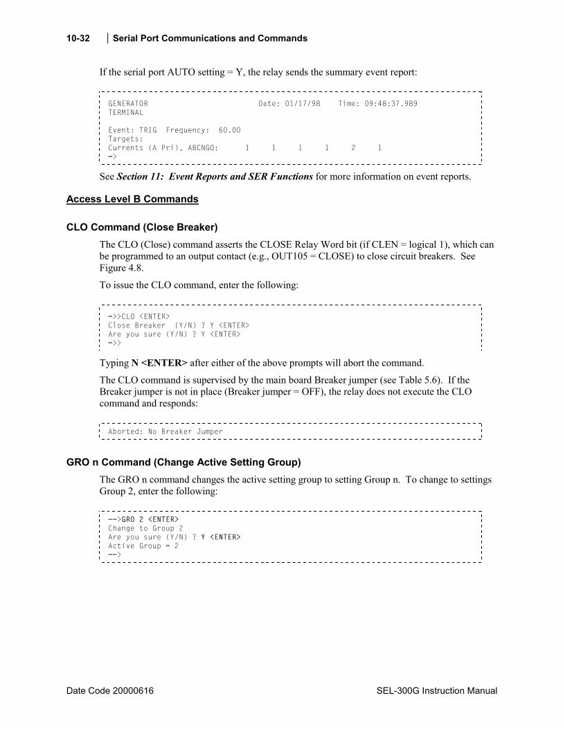
10-32 Serial Port Communications and Commands
Date Code 20000616 SEL-300G Instruction Manual
If the serial port AUTO setting = Y, the relay sends the summary event report:
GENERATOR Date: 01/17/98 Time: 09:48:37.989 TERMINAL Event: TRIG Frequency: 60.00 Targets: Currents (A Pri), ABCNGQ: 1 1 1 1 2 1 =>
See Section 11: Event Reports and SER Functions for more information on event reports.
Access Level B Commands
CLO Command (Close Breaker) The CLO (Close) command asserts the CLOSE Relay Word bit (if CLEN = logical 1), which can be programmed to an output contact (e.g., OUT105 = CLOSE) to close circuit breakers. See Figure 4.8.
To issue the CLO command, enter the following:
=>>CLO <ENTER> Close Breaker (Y/N) ? Y <ENTER> Are you sure (Y/N) ? Y <ENTER> =>>
Typing N <ENTER> after either of the above prompts will abort the command.
The CLO command is supervised by the main board Breaker jumper (see Table 5.6). If the Breaker jumper is not in place (Breaker jumper = OFF), the relay does not execute the CLO command and responds:
Aborted: No Breaker Jumper
GRO n Command (Change Active Setting Group) The GRO n command changes the active setting group to setting Group n. To change to settings Group 2, enter the following:
==>GRO 2 <ENTER> Change to Group 2 Are you sure (Y/N) ? Y <ENTER> Active Group = 2 ==>
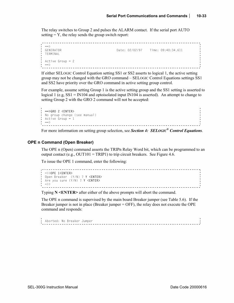
Serial Port Communications and Commands 10-33
SEL-300G Instruction Manual Date Code 20000616
The relay switches to Group 2 and pulses the ALARM contact. If the serial port AUTO setting = Y, the relay sends the group switch report:
==> GENERATOR Date: 02/02/97 Time: 09:40:34.611 TERMINAL Active Group = 2 ==>
If either SELOGIC Control Equation setting SS1 or SS2 asserts to logical 1, the active setting group may not be changed with the GRO command SELOGIC Control Equations settings SS1 and SS2 have priority over the GRO command in active setting group control.
For example, assume setting Group 1 is the active setting group and the SS1 setting is asserted to logical 1 (e.g, SS1 = IN104 and optoisolated input IN104 is asserted). An attempt to change to setting Group 2 with the GRO 2 command will not be accepted:
==>GRO 2 <ENTER> No group change (see manual) Active Group = 1 ==>
For more information on setting group selection, see Section 4: SELOGIC® Control Equations.
OPE n Command (Open Breaker) The OPE n (Open) command asserts the TRIPn Relay Word bit, which can be programmed to an output contact (e.g., OUT101 = TRIP1) to trip circuit breakers. See Figure 4.6.
To issue the OPE 1 command, enter the following:
=>>OPE 1<ENTER> Open Breaker (Y/N) ? Y <ENTER> Are you sure (Y/N) ? Y <ENTER> =>>
Typing N <ENTER> after either of the above prompts will abort the command.
The OPE n command is supervised by the main board Breaker jumper (see Table 5.6). If the Breaker jumper is not in place (Breaker jumper = OFF), the relay does not execute the OPE command and responds:
Aborted: No Breaker Jumper

10-34 Serial Port Communications and Commands
Date Code 20000616 SEL-300G Instruction Manual
PUL Command (Pulse Output Contact) The PUL command allows you to pulse any of the output contacts for a specified length of time. The command format is:
PUL x y
where: x is the output name (e.g., OUT107, ALARM, OUT211 - see Figure 4.16 and Figure 4.17).
y is the pulse duration (1-30) in seconds. If y is not specified, the pulse duration defaults to 1 second.
To pulse OUT101 for 5 seconds:
=>>PUL OUT101 5 <ENTER> Are you sure (Y/N) ? Y <ENTER> =>>
If the response to the Are you sure (Y/N) ? prompt is N or n, the command is aborted.
The PUL command is supervised by the main board Breaker jumper (see Table 5.6). If the Breaker is not in place (Breaker jumper = OFF), the relay does not execute the PUL command and responds:
Aborted: No Breaker Jumper
The relay generates an event report if any of the OUT101 through OUT107 contacts or OUT201 through OUT212 (Models 0300G_1) are pulsed. The PUL command is used primarily for testing purposes.
Access Level 2 Commands
BRE n Command (Preload/Reset Breaker Wear) Use the BRE W command to preload breaker wear. For example, to preload the breaker wear to 25%, 28%, and 24% for the respective phases, issue the command below.
==>BRE W <ENTER> Breaker Wear Percent Preload A-phase % = 0 ? 10 B-phase % = 0 ? 12 C-phase % = 0 ? 10 Are you sure (Y/N) ? y GENERATOR Date: 01/17/98 Time: 10:04:11.330 TERMINAL Int Trips= 0 IA= 0.0 IB= 0.0 IC= 0.0 kA Ext Trips= 0 IA= 0.0 IB= 0.0 IC= 0.0 kA Percent wear: A= 10 B= 12 C= 10 LAST RESET 01/17/98 09:45:35 ==>
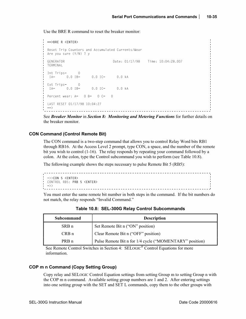
Serial Port Communications and Commands 10-35
SEL-300G Instruction Manual Date Code 20000616
Use the BRE R command to reset the breaker monitor:
==>BRE R <ENTER> Reset Trip Counters and Accumulated Currents/Wear Are you sure (Y/N) ? y GENERATOR Date: 01/17/98 Time: 10:04:28.007 TERMINAL Int Trips= 0 IA= 0.0 IB= 0.0 IC= 0.0 kA Ext Trips= 0 IA= 0.0 IB= 0.0 IC= 0.0 kA Percent wear: A= 0 B= 0 C= 0 LAST RESET 01/17/98 10:04:27 ==>
See Breaker Monitor in Section 8: Monitoring and Metering Functions for further details on the breaker monitor.
CON Command (Control Remote Bit) The CON command is a two-step command that allows you to control Relay Word bits RB1 through RB16. At the Access Level 2 prompt, type CON, a space, and the number of the remote bit you wish to control (1-16). The relay responds by repeating your command followed by a colon. At the colon, type the Control subcommand you wish to perform (see Table 10.8).
The following example shows the steps necessary to pulse Remote Bit 5 (RB5):
=>>CON 5 <ENTER> CONTROL RB5: PRB 5 <ENTER> =>>
You must enter the same remote bit number in both steps in the command. If the bit numbers do not match, the relay responds Invalid Command.
Table 10.8: SEL-300G Relay Control Subcommands
Subcommand Description
SRB n Set Remote Bit n (ON position)
CRB n Clear Remote Bit n (OFF position)
PRB n Pulse Remote Bit n for 1/4 cycle (MOMENTARY position) See Remote Control Switches in Section 4: SELOGIC® Control Equations for more information.
COP m n Command (Copy Setting Group) Copy relay and SELOGIC Control Equation settings from setting Group m to setting Group n with the COP m n command. Available setting group numbers are 1 and 2. After entering settings into one setting group with the SET and SET L commands, copy them to the other groups with
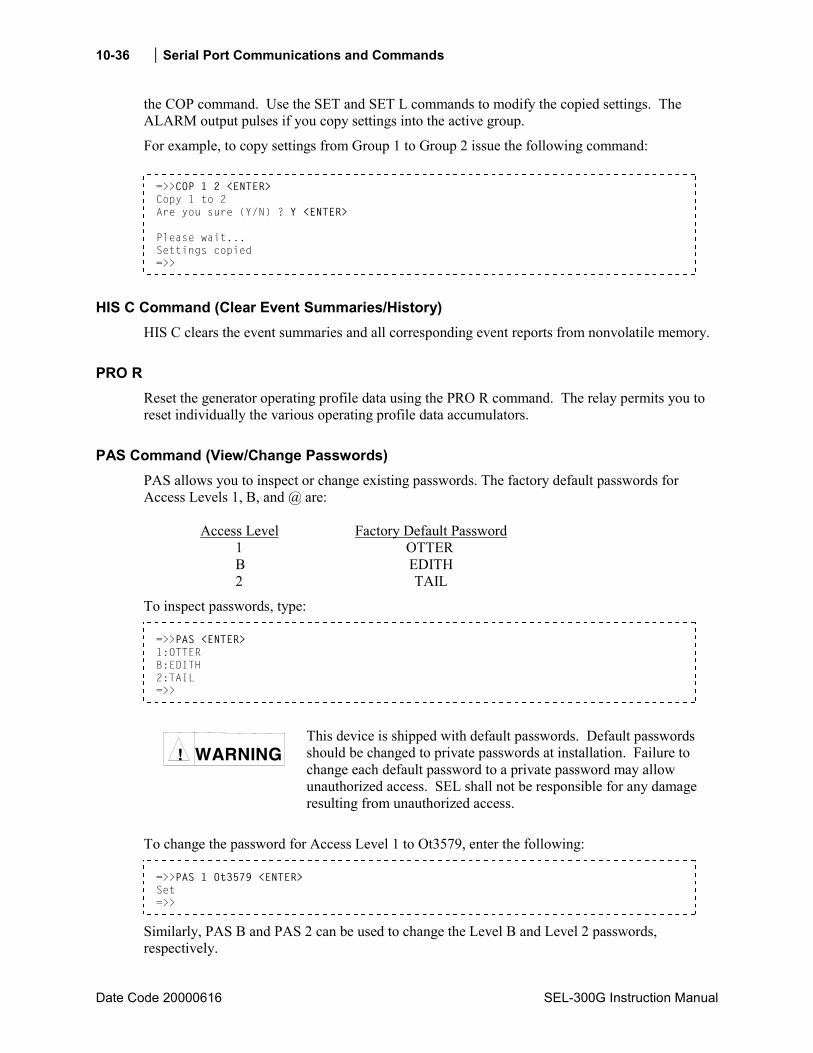
10-36 Serial Port Communications and Commands
Date Code 20000616 SEL-300G Instruction Manual
the COP command. Use the SET and SET L commands to modify the copied settings. The ALARM output pulses if you copy settings into the active group.
For example, to copy settings from Group 1 to Group 2 issue the following command:
=>>COP 1 2 <ENTER> Copy 1 to 2 Are you sure (Y/N) ? Y <ENTER> Please wait... Settings copied =>>
HIS C Command (Clear Event Summaries/History) HIS C clears the event summaries and all corresponding event reports from nonvolatile memory.
PRO R Reset the generator operating profile data using the PRO R command. The relay permits you to reset individually the various operating profile data accumulators.
PAS Command (View/Change Passwords) PAS allows you to inspect or change existing passwords. The factory default passwords for Access Levels 1, B, and @ are: Access Level Factory Default Password
1 OTTER B EDITH 2 TAIL
To inspect passwords, type:
=>>PAS <ENTER> 1:OTTER B:EDITH 2:TAIL =>>
WARNING !
This device is shipped with default passwords. Default passwords should be changed to private passwords at installation. Failure to change each default password to a private password may allow unauthorized access. SEL shall not be responsible for any damage resulting from unauthorized access.
To change the password for Access Level 1 to Ot3579, enter the following:
=>>PAS 1 Ot3579 <ENTER> Set =>>
Similarly, PAS B and PAS 2 can be used to change the Level B and Level 2 passwords, respectively.
Serial Port Communications and Commands 10-37
SEL-300G Instruction Manual Date Code 20000616
Passwords may include up to six characters. Valid characters consist of: A-Z, a-z, 0-9, -, and .. Upper- and lowercase letters are treated as different characters.
Strong passwords consist of six characters, with at least one special character or digit and mixed case sensitivity, but do not form a name, date, acronym, or word. Passwords formed in this manner are less susceptible to password guessing and automated attacks. Examples of valid, distinct strong passwords include:
Ot3579 A24.68 Ih2dcs 4u-Iwg .351r.
After entering new passwords, type PAS <ENTER> to inspect them. Make sure they are what you intended, and record the new passwords. If the passwords are lost or you wish to operate the relay without password protection, put the main board Password jumper in place (Password jumper = ON). Refer to Table 5.6 for Password jumper information.
If you wish to disable password protection for a specific access level [even if Password jumper is not in place (Password jumper = OFF)], simply set the password to DISABLE. For example PAS 1 DISABLE disables password protection for Level 1.
SET Command (Change Settings) The SET command allows the user to view or change the relay settings see Table 6.1 in Section 6: Enter Relay Settings.
STA C To reset the self-test statuses, use the STA C command from Access Level 2:
=>>STA C <ENTER>
The relay responds:
Reboot the relay and clear status Are you sure (Y/N) ?
If you select N or n, the relay displays:
Canceled
and aborts the command.
If you select Y, the relay displays:
Rebooting the relay
The relay then restarts (just like powering down, then powering up relay), and all diagnostics are rerun before the relay is enabled.

10-38 Serial Port Communications and Commands
Date Code 20000616 SEL-300G Instruction Manual
SYN R (Models 0300G2, 0300G3) The SYN R command allows the operator to clear synch-check reports and reset the synchronization function breakers average close time and close counter. Use the SYN R command from Access Level 2.
SERIAL PORT ERROR MESSAGES The relay will generate error messages in response to serial port commands or arguments that it does not recognize. The following table lists the error messages and their causes and suggests corrections.
Table 10.9: SEL-300G Error Messages
Error Message Command Executed
This Message Occurs When:
To Correct:
Aborted. No Breaker Jumper
CLOSE, OPEN, PULSE
Breaker jumper on main board is not installed.
Install main board jumper JMP6-B before executing breaker control commands.
Command Aborted, Relay Disabled
Any Command
The relay is disabled. Check ALARM contact, STATUS command to determine if and why relay is disabled.
Did not trigger TRIGGER Another event is in progress. Wait a moment for event in progress to complete and save, then try again.
Did not trigger TRIGGER The event buffer is full. Wait a moment for the event in progress to complete and save, then try again.
Did not trigger TRIGGER The relay is disabled. Check ALARM Contact, STATUS command to determine if and why relay is disabled.
Invalid Access Level
Any Command
Serial port is not at the proper access level to execute the command.
Move to the correct Access Level using the ACC, BAC, and 2AC commands and associated passwords.
Invalid Command Any Command
Command was not recognized by the relay.
Use the HELP command to find the commands available at the present Access Level.
Invalid Command COPY Copy source or destination is unknown.
Use COPY 1 2 to copy from Group 1 settings to Group 2 or COPY 2 1 to copy from Group 2 settings to Group 1.
Invalid Command GROUP n Relay setting group n is not a valid group.
Use GROUP 1 or GROUP 2.
Invalid Command SET n SHO n
Relay setting name n was not recognized as a valid setting name.
Use the Settings Sheets in Section 6: Enter Relay Settings to determine the correct name of the desired setting.

Serial Port Communications and Commands 10-39
SEL-300G Instruction Manual Date Code 20000616
Error Message Command Executed
This Message Occurs When:
To Correct:
Invalid Data SYN No synch-check report data available.
Execute the command again after a generator paralleling operation when data will be available.
Invalid Date DATE Date entered is not in a valid format.
Use the HELP DAT command to view acceptable formats and then key the command using an acceptable date and format.
Invalid Event EVE n Fewer than n event reports presently are stored.
Use the HISTORY command to learn how many events are presently stored.
Invalid Password ACC, BAC, 2AC
Password entered is incorrect for the attempted Access Level.
Rekey command to correct typographical error, or obtain correct password.
Invalid Target TARGET n Relay Word Bit name n was not recognized as a valid name.
Use the tables in Section 4: SELOGIC® Control Equations to determine the correct name of the desired Relay Word bit.
Invalid Time TIME Time entered is not in a valid format.
Use the HELP TIM command to view acceptable formats and then rekey the command.
IRIG-B DATA ERROR
IRIG Demodulated IRIG-B signal is not connected or detected by relay.
Verify cabling and connections, then retry the command.
No group change (see manual)
GROUP SS1 or SS2 asserted during group change. SS1 and SS2 control equations have precedence over serial port command group selection.
Verify that SS1 or SS2 should be asserted at this time, based on your application.
No SER Data SER The SER data buffer is empty.
Execute the SER command again after one or more SER triggering transitions have occurred.
Requested option not ordered in this relay
EVE DIF The relay is not equipped with current differential elements and so does not create this type of event report.
Synch-check option not ordered in this relay
SYN Relay is not equipped with synch-check elements and so does not create this type of event report.

SEL-300G Instruction Manual Date Code 20020206
TABLE OF CONTENTS
SECTION 11: EVENT REPORTS AND SER FUNCTIONS.................11-1
Introduction .................................................................................................................................11-1 Standard 15/30-Cycle Event Reports ..........................................................................................11-1
Event Report Length (Settings LER and PRE) ...................................................................11-1 Standard Event Report Triggering ......................................................................................11-2
Relay Word Bit TRIP1 through TRIP4 .......................................................................11-2 Programmable SELOGIC® Control Equation Setting ER.............................................11-2 TRI (Trigger Event Report) and PUL (Pulse Output Contact) Commands ................11-3
Standard Event Report Summary ........................................................................................11-3 Event Type...................................................................................................................11-4 Targets .........................................................................................................................11-4 Currents .......................................................................................................................11-4
Retrieving Full-Length Standard Event Reports .................................................................11-4 Compressed ASCII Event Reports ......................................................................................11-6 Filtered and Unfiltered Event Reports ................................................................................11-6 Clearing Standard Event Report Buffer ..............................................................................11-6 Standard Event Report Column Definitions........................................................................11-6
Current, Voltage, and Frequency Columns .................................................................11-7 Output, Input, Protection and Control Columns..........................................................11-7
Differential Event Report Column Definitions (Models 0300G1 and 0300G3)...............11-15 Current Columns .......................................................................................................11-16 Differential Element, Output, and Input Columns ....................................................11-16 Differential Current Magnitudes and Control Elements ...........................................11-17
Sequential Events Recorder (SER) Report ...............................................................................11-18 SER Triggering..................................................................................................................11-18 Making SER Trigger Settings ...........................................................................................11-18 Retrieving SER Reports ....................................................................................................11-18 Clearing SER Report .........................................................................................................11-20
Synchronism Checking Report (Models 0300G2, 0300G3) .....................................................11-20 SYN Report Triggering.....................................................................................................11-20 Conditions When CLOSE Asserted ..................................................................................11-21 SYN Report Closure..........................................................................................................11-21 Use the Breaker Close Time Average ...............................................................................11-22 Reset the Breaker Close Time Average ............................................................................11-22
Example Standard 15-Cycle Event Report................................................................................11-22 Example Sequential Events Recorder (SER) Report ................................................................11-30 Differential Event Report Headers............................................................................................11-31

ii Event Reports and SER Functions
Date Code 20020206 SEL-300G Instruction Manual
TABLES Table 11.1: Event Types .........................................................................................................................11-4 Table 11.2: Standard Event Report Current, Voltage, and Frequency Columns ....................................11-7 Table 11.3: Output, Input, and Protection and Control Element Event Report Columns.......................11-8 Table 11.4: Differential Event Report Current Columns......................................................................11-16 Table 11.5: Differential Element, Output, and Input Event Report Columns ......................................11-16
FIGURES Figure 11.1: Example Event Summary ...................................................................................................11-3 Figure 11.2: Example Standard 15-Cycle Event Report 1/4-Cycle Resolution....................................11-27 Figure 11.3: Derivation of Event Report Current Values and RMS Current Values From
Sampled Current Waveform.......................................................................................11-28 Figure 11.4: Derivation of Phasor RMS Current Values From Event Report Current Values.............11-29 Figure 11.5: Example Sequential Events Recorder (SER) Event Report .............................................11-30 Figure 11.6: Example Differential Event Report 1/4-Cycle Resolution ...............................................11-32
Event Reports and SER Functions 11-1
SEL-300G Instruction Manual Date Code 20020206
SECTION 11: EVENT REPORTS AND SER FUNCTIONS
INTRODUCTION The SEL-300G Relay offers two styles of event reports:
• Standard 15/30-cycle event reports
• Sequential Events Recorder (SER) report
Resolution: 1 ms Accuracy: +1/4 cycle
These event reports contain date, time, current, voltage, frequency, relay element, optoisolated input, and output contact information. Event reports generated by SEL-300G_1 Relays also include data describing the operation of the differential measurements and elements.
The relay generates (triggers) standard 15/30-cycle event reports by fixed and programmable conditions. These reports show information for 15 or 30 continuous cycles. The relay stores the event report data in nonvolatile memory. Up to twenty-nine 15-cycle or fifteen 30-cycle reports are maintained; if more reports are triggered, the latest event report overwrites the oldest event report. See Figure 11.2 for an example standard 15-cycle event report.
The relay adds lines in the SER report for a change of state of a programmable condition. The SER lists date and time-stamped lines of information each time a programmed condition changes state. The relay stores the latest 512 lines of the SER report in nonvolatile memory. If the report fills up, newer rows overwrite the oldest rows in the report. See Figure 11.5 for an example SER report.
Relays equipped with synchronism checking also generate reports showing relay and breaker performance during synch-check supervised closes.
STANDARD 15/30-CYCLE EVENT REPORTS See Figure 11.2 for an example event report (Note: Figure 11.2 is on multiple pages).
Event Report Length (Settings LER and PRE)
The SEL-300G Relay provides user-programmable event report length and prefault length. Event report length is either 15 or 30 cycles. Prefault length ranges from 1 to LER-1 cycles. Prefault length is the first part of the event report that precedes the event report triggering point.
Set the event report length with the LER setting. Set the prefault length with the PRE setting.
Changing the LER setting will erase all events stored in nonvolatile memory. Changing the PRE setting has no effect on the nonvolatile reports.

11-2 Event Reports and SER Functions
Date Code 20020206 SEL-300G Instruction Manual
Standard Event Report Triggering
The relay triggers (generates) a standard event report when any of the following occur:
• Relay Word bit TRIP1 through TRIP4 assert
• Programmable SELOGIC® Control Equation setting ER asserts to logical 1
• TRI (Trigger Event Reports) serial port command executed
• Output contacts OUT101 through OUT107 (All models) or OUT201 through OUT212 (Model 0300G_1) pulsed via the serial port or front-panel PUL (Pulse Output Contact) command
Relay Word Bit TRIP1 through TRIP4
Refer to Figure 4.6. If any of Relay Word bits TRIP1 through TRIP4 assert to logical 1, an event report is automatically generated. Thus, any condition that causes a trip does not have to be entered in SELOGIC Control Equation setting ER.
Relay Word bits TRIP1 through TRIP4 (in Figure 4.6) are usually assigned to output contacts for tripping circuit breakers, etc.
Programmable SELOGIC® Control Equation Setting ER
The programmable SELOGIC Control Equation event report trigger setting ER is set to trigger standard event reports for conditions other than trip conditions. When setting ER sees a logical 0 to logical 1 transition, it generates an event report (if the SEL-300G Relay is not already generating a report that encompasses the new transition). The factory setting is:
ER = /24C2 + /32P1 + /46Q2 + /51N + /51C + /51V + /64G1 + /64G2
+ /60LOP + /81D1 + /81D2 + \81D1 + \81D2 + /BNDA + /BNDT + /INAD
Note the rising edge operator, /, in front of some of these elements. Rising edge operators are especially useful in generating an event report at fault inception and then generating another later if a breaker failure condition occurs. For example, at the inception of a stator ground fault, pickup indicator 64G1 asserts and an event report is generated:
ER = ... + /64G1 + ... = logical 1 (for one processing interval)
Even though the 64G1 pickup indicator will remain asserted for the duration of the ground fault, the rising edge operator, /, in front of 64G1 (/64G1) causes setting ER to be asserted for only one processing interval.
Falling edge operators, \, are also used to generate event reports as in the case of \81D1 + \81D2 +... See Section 4: SELOGIC® Control Equations for more information on falling edge operators.
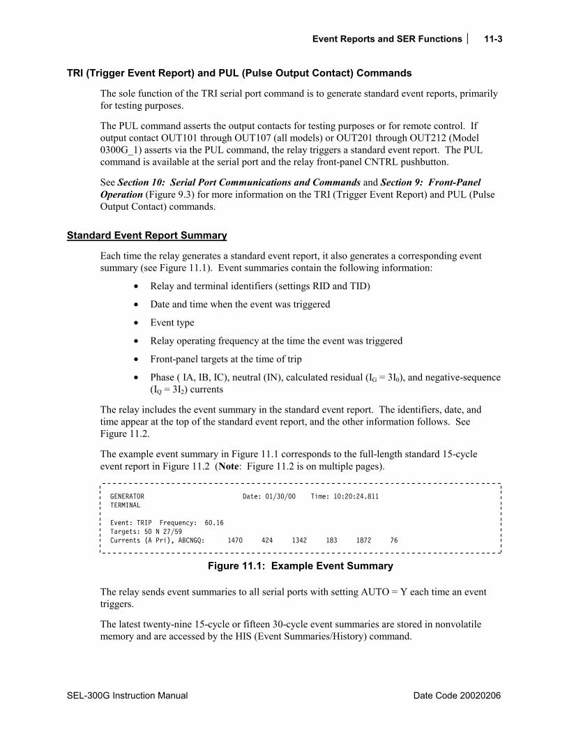
Event Reports and SER Functions 11-3
SEL-300G Instruction Manual Date Code 20020206
TRI (Trigger Event Report) and PUL (Pulse Output Contact) Commands
The sole function of the TRI serial port command is to generate standard event reports, primarily for testing purposes.
The PUL command asserts the output contacts for testing purposes or for remote control. If output contact OUT101 through OUT107 (all models) or OUT201 through OUT212 (Model 0300G_1) asserts via the PUL command, the relay triggers a standard event report. The PUL command is available at the serial port and the relay front-panel CNTRL pushbutton.
See Section 10: Serial Port Communications and Commands and Section 9: Front-Panel Operation (Figure 9.3) for more information on the TRI (Trigger Event Report) and PUL (Pulse Output Contact) commands.
Standard Event Report Summary
Each time the relay generates a standard event report, it also generates a corresponding event summary (see Figure 11.1). Event summaries contain the following information:
• Relay and terminal identifiers (settings RID and TID)
• Date and time when the event was triggered
• Event type
• Relay operating frequency at the time the event was triggered
• Front-panel targets at the time of trip
• Phase ( IA, IB, IC), neutral (IN), calculated residual (IG = 3I0), and negative-sequence (IQ = 3I2) currents
The relay includes the event summary in the standard event report. The identifiers, date, and time appear at the top of the standard event report, and the other information follows. See Figure 11.2.
The example event summary in Figure 11.1 corresponds to the full-length standard 15-cycle event report in Figure 11.2 (Note: Figure 11.2 is on multiple pages).
GENERATOR Date: 01/30/00 Time: 10:20:24.811 TERMINAL Event: TRIP Frequency: 60.16 Targets: 50 N 27/59 Currents (A Pri), ABCNGQ: 1470 424 1342 183 1872 76
Figure 11.1: Example Event Summary
The relay sends event summaries to all serial ports with setting AUTO = Y each time an event triggers.
The latest twenty-nine 15-cycle or fifteen 30-cycle event summaries are stored in nonvolatile memory and are accessed by the HIS (Event Summaries/History) command.

11-4 Event Reports and SER Functions
Date Code 20020206 SEL-300G Instruction Manual
Event Type
The Event: field shows the event type. The possible event types and their descriptions are shown in the table below. Note the correspondence to the preceding event report triggering conditions (see Standard Event Report Triggering in this section).
Table 11.1: Event Types
Event Type Description TRIP Assertion of Relay Word bits TRIP1 through TRIP4
ER SELOGIC Control Equation setting ER
TRIG Execution of TRIGGER command
PULSE Execution of PULSE command
Targets
The relay reports the targets at the rising edge of TRIP1, TRIP2, TRIP3, or TRIP4. If there is no rising edge of TRIP in the report, the Targets field is blank. See Front-Panel Target LEDs in Section 9: Front-Panel Operation.
Currents
The Currents (A pri), ABCNGQ: field shows the currents present in the event report row containing the maximum phase current. The listed currents are:
Phase (A = channel IA, B = channel IB, C = channel IC) Neutral (N = channel IN) Calculated residual (IG = 3I0; calculated from channels IA, IB, and IC) Negative-sequence (Q = 3I2; calculated from channels IA, IB, and IC)
Retrieving Full-Length Standard Event Reports
The latest twenty-nine 15-cycle or fifteen 30-cycle event reports are stored in nonvolatile memory. Each event report includes four sections:
• Current, voltage, station battery, frequency, contact outputs, optoisolated inputs
• Protection and control elements (different for various relay models)
• Event summary
• Group and global settings
Use the EVE command to retrieve the reports. There are several options to customize the report format. The general command format is:
EVE [n DIF Sx Ly[-[w]] R A D C]
Event Reports and SER Functions 11-5
SEL-300G Instruction Manual Date Code 20020206
where:
n Event number (1 29) if LER = 15; (1 15) if LER = 30. Defaults to 1 if not listed, where 1 is the most recent event.
DIF Display differential element event report.
Sx Display x samples per cycle (4 or 16); defaults to 4 if not listed.
Ly Display y cycles of data (1 LER). Defaults to LER value if not listed. Unfiltered reports (R parameter) display an extra cycle of data.
Ly- Display event data from cycle y to the end of the report.
Ly-w Display event data from cycle y to cycle w.
R Specifies the unfiltered (raw) event report. Defaults to 16 samples per cycle unless overridden with the Sx parameter.
A Specifies that only the analog section of the event is displayed (current, voltage, station battery, frequency, contact outputs, optoisolated inputs).
D Specifies that only the digital section (Protection and Control Elements) of the event is displayed.
C Displays a 15-cycle report with 1/16-cycle resolution and primary scaling. This report includes analog, digital, and settings information.
Below are example EVE commands.
Serial Port Command Description
EVE Display the most recent event report at 1/4-cycle resolution. EVE 2 Display the second event report at 1/4-cycle resolution. EVE S16 L10 Display 10 cycles of the most recent report at 1/16-cycle resolution. EVE C 2 Display 15 cycles of the second event report at 1/16-cycle resolution. EVE R Display most recent report at 1/16-cycle resolution; analog data are unfiltered
(raw). EVE 2 D L10 Display 10 cycles of the protection and control elements section of the second
event report at 1/4-cycle resolution. EVE 2 A R S4 Display the unfiltered analog section of the second event report at 1/4-cycle
resolution.
If an event report is requested that does not exist, the relay responds:
Invalid Event
11-6 Event Reports and SER Functions
Date Code 20020206 SEL-300G Instruction Manual
Compressed ASCII Event Reports
The SEL-300G Relay provides compressed ASCII event reports to facilitate event report storage and display. It also includes additional information (e.g., status of all Relay Word Bits) not available in the reports retrieved using the EVE command. The SEL-2020, or the SEL-2030, Communications Processor and the SEL-5601 Analytic Assistant software take advantage of the compressed ASCII format. Use the CEVENT command to display compressed ASCII event reports. See the CEVENT command discussion in Appendix E: Compressed ASCII Commands for further information.
Filtered and Unfiltered Event Reports
The SEL-300G Relay samples the basic power system measurands (ac voltage, ac current, station battery, and optoisolated inputs) 16 times per power system cycle. The relay filters the measurands to remove transient signals. The relay operates on the filtered values and reports them in the event report.
To view the raw inputs to the relay, select the unfiltered event report (e.g., EVE R). Use the unfiltered event reports to observe:
• Power system harmonics on channels IA, IB, IC, IN, VA, VB, VC, VN
• Decaying dc offset during fault conditions on IA, IB, IC
• Optoisolated input contact bounce on IN101 through IN106
• Transients on the station dc battery channel Vdc (power input terminals Z25 and Z26)
The filters for ac current, voltage, and station battery are fixed. You can adjust the optoisolated input debounce via debounce settings (see Figures 3.12 and 3.13 in Section 3: Auxiliary Function Settings).
Raw event reports display one extra cycle of data at the beginning of the report.
Clearing Standard Event Report Buffer
The HIS C command clears the event summaries and corresponding standard event reports from nonvolatile memory. See Section 10: Serial Port Communications and Commands for more information on the HIS (Event Summaries/History) command.
Standard Event Report Column Definitions
Refer to the example event report (Figure 11.2) to view event report columns (Note: Figure 11.2 is on multiple pages). This example event report displays rows of information each 1/4 cycle and was retrieved with the EVE command.
The columns contain ac current, ac voltage, station dc battery voltage, frequency, output, input, and protection and control element information.
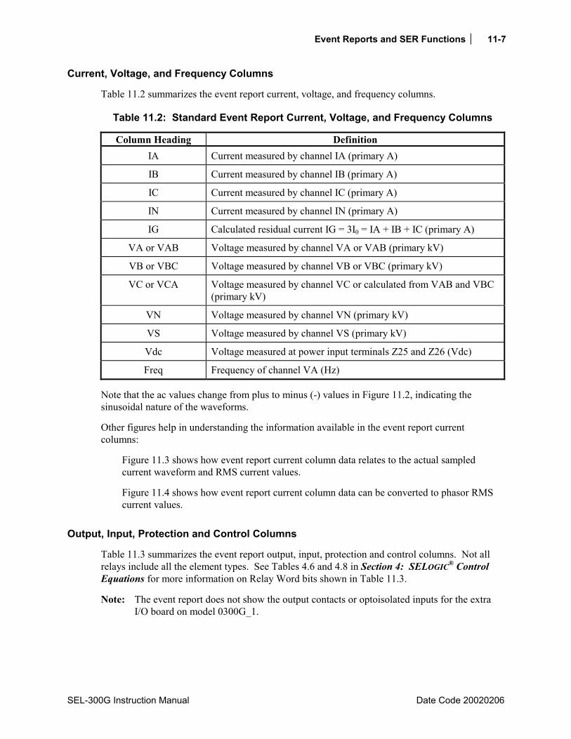
Event Reports and SER Functions 11-7
SEL-300G Instruction Manual Date Code 20020206
Current, Voltage, and Frequency Columns
Table 11.2 summarizes the event report current, voltage, and frequency columns.
Table 11.2: Standard Event Report Current, Voltage, and Frequency Columns
Column Heading Definition IA Current measured by channel IA (primary A)
IB Current measured by channel IB (primary A)
IC Current measured by channel IC (primary A)
IN Current measured by channel IN (primary A)
IG Calculated residual current IG = 3I0 = IA + IB + IC (primary A)
VA or VAB Voltage measured by channel VA or VAB (primary kV)
VB or VBC Voltage measured by channel VB or VBC (primary kV)
VC or VCA Voltage measured by channel VC or calculated from VAB and VBC (primary kV)
VN Voltage measured by channel VN (primary kV)
VS Voltage measured by channel VS (primary kV)
Vdc Voltage measured at power input terminals Z25 and Z26 (Vdc)
Freq Frequency of channel VA (Hz)
Note that the ac values change from plus to minus (-) values in Figure 11.2, indicating the sinusoidal nature of the waveforms.
Other figures help in understanding the information available in the event report current columns:
Figure 11.3 shows how event report current column data relates to the actual sampled current waveform and RMS current values.
Figure 11.4 shows how event report current column data can be converted to phasor RMS current values.
Output, Input, Protection and Control Columns
Table 11.3 summarizes the event report output, input, protection and control columns. Not all relays include all the element types. See Tables 4.6 and 4.8 in Section 4: SELOGIC® Control Equations for more information on Relay Word bits shown in Table 11.3.
Note: The event report does not show the output contacts or optoisolated inputs for the extra I/O board on model 0300G_1.
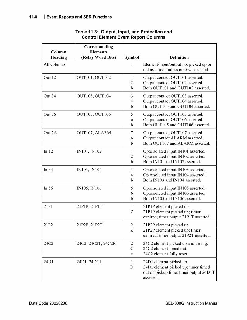
11-8 Event Reports and SER Functions
Date Code 20020206 SEL-300G Instruction Manual
Table 11.3: Output, Input, and Protection and Control Element Event Report Columns
Column Heading
Corresponding Elements
(Relay Word Bits) Symbol Definition All columns . Element/input/output not picked up or
not asserted, unless otherwise stated.
Out 12 OUT101, OUT102 1 Output contact OUT101 asserted. 2 Output contact OUT102 asserted. b Both OUT101 and OUT102 asserted.
Out 34 OUT103, OUT104 3 Output contact OUT103 asserted. 4 Output contact OUT104 asserted. b Both OUT103 and OUT104 asserted.
Out 56 OUT105, OUT106 5 Output contact OUT105 asserted. 6 Output contact OUT106 asserted. b Both OUT105 and OUT106 asserted.
Out 7A OUT107, ALARM 7 Output contact OUT107 asserted. A Output contact ALARM asserted. b Both OUT107 and ALARM asserted.
In 12 IN101, IN102 1 Optoisolated input IN101 asserted. 2 Optoisolated input IN102 asserted. b Both IN101 and IN102 asserted.
In 34 IN103, IN104 3 Optoisolated input IN103 asserted. 4 Optoisolated input IN104 asserted. b Both IN103 and IN104 asserted.
In 56 IN105, IN106 5 Optoisolated input IN105 asserted. 6 Optoisolated input IN106 asserted. b Both IN105 and IN106 asserted.
21P1 21P1P, 21P1T 1 21P1P element picked up. Z 21P1P element picked up; timer
expired; timer output 21P1T asserted.
21P2 21P2P, 21P2T 2 21P2P element picked up. Z 21P2P element picked up; timer
expired; timer output 21P2T asserted.
24C2 24C2, 24C2T, 24C2R 2 C
24C2 element picked up and timing. 24C2 element timed out.
r 24C2 element fully reset.
24D1 24D1, 24D1T 1 24D1 element picked up. D 24D1 element picked up; timer timed
out on pickup time; timer output 24D1T asserted.

Event Reports and SER Functions 11-9
SEL-300G Instruction Manual Date Code 20020206
Column Heading
Corresponding Elements
(Relay Word Bits) Symbol Definition 25SF SF * 25SLO setting < Slip Frequency <
25SHI setting.
25A 25A1, 25A2, 25C 1 Compensated phase angle magnitude < 25ANG1 setting.
2 Uncompensated phase angle magnitude < 25ANG2 setting.
b Both 25A1 and 25A2 are picked up. C 25C picked up.
GENV GENVHI, GENVLO + GENVHI picked up, indicating generator voltage is higher than system voltage.
- GENVLO picked up, indicating generator voltage is lower than system voltage.
GENF GENFHI, GENFLO + GENFHI picked up, indicating slip frequency greater than 25SHI setting.
- GENFLO picked up, indicating slip frequency less than 25SLO setting.
27PV 27P1, 27P2, 27V1 1 Level 1 (27P1) instantaneous phase undervoltage element picked up.
2 Level 2 (27P2) instantaneous phase undervoltage element picked up.
b Both Level 1 and Level 2 phase undervoltage elements picked up.
V 27V1 positive-sequence undervoltage element picked up.
B 27V1 and 27P1 picked up. P 27V1 and 27P2 picked up. 3 27P1, 27P2, and 27V1 picked up.
27PP 27PP1, 27PP2 1 Level 1 phase-to-phase undervoltage element picked up.
2 Level 2 phase-to-phase undervoltage element picked up.
b Both Level 1 and Level 2 phase-to-phase undervoltage elements picked up.
27VS 27VS S Synch-check (VS) input undervoltage element picked up.
32P1 32P1, 32P1T 1 Level 1 reverse/low-forward power instantaneous element picked up.
P 32P1 picked up, 32P1T timed out.
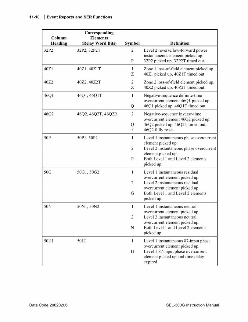
11-10 Event Reports and SER Functions
Date Code 20020206 SEL-300G Instruction Manual
Column Heading
Corresponding Elements
(Relay Word Bits) Symbol Definition 32P2 32P2, 32P2T 2 Level 2 reverse/low-forward power
instantaneous element picked up. P 32P2 picked up, 32P2T timed out.
40Z1 40Z1, 40Z1T 1 Zone 1 loss-of-field element picked up. Z 40Z1 picked up, 40Z1T timed out.
40Z2 40Z2, 40Z2T 2 Zone 2 loss-of-field element picked up. Z 40Z2 picked up, 40Z2T timed out.
46Q1 46Q1, 46Q1T 1 Negative-sequence definite-time overcurrent element 46Q1 picked up.
Q 46Q1 picked up, 46Q1T timed out.
46Q2 46Q2, 46Q2T, 46Q2R 2 Negative-sequence inverse-time overcurrent element 46Q2 picked up.
Q 46Q2 picked up, 46Q2T timed out. r 46Q2 fully reset.
50P 50P1, 50P2 1 Level 1 instantaneous phase overcurrent element picked up.
2 Level 2 instantaneous phase overcurrent element picked up.
P Both Level 1 and Level 2 elements picked up.
50G 50G1, 50G2 1 Level 1 instantaneous residual overcurrent element picked up.
2 Level 2 instantaneous residual overcurrent element picked up.
G Both Level 1 and Level 2 elements picked up.
50N 50N1, 50N2 1 Level 1 instantaneous neutral overcurrent element picked up.
2 Level 2 instantaneous neutral overcurrent element picked up.
N Both Level 1 and Level 2 elements picked up.
50H1 50H1 1 Level 1 instantaneous 87-input phase overcurrent element picked up.
H Level 1 87-input phase overcurrent element picked up and time delay expired.

Event Reports and SER Functions 11-11
SEL-300G Instruction Manual Date Code 20020206
Column Heading
Corresponding Elements
(Relay Word Bits) Symbol Definition 50H2 50H2A, 50H2B,
50H2C, 50H2T a A-Phase Level 2 instantaneous 87-input
phase overcurrent element picked up. b B-Phase Level 2 instantaneous 87-input
phase overcurrent element picked up. c C-Phase Level 2 instantaneous 87-input
phase overcurrent element picked up. * Two or more Level 2 instantaneous
87-input phase overcurrent elements picked up.
H Level 2 87-input phase overcurrent element picked up and time delay expired.
50Q 50Q1, 50Q2 1 Level 1 instantaneous 87-input negative-sequence overcurrent element picked up.
2 Level 2 instantaneous 87-input negative-sequence overcurrent element picked up.
Q Both Level 1 and Level 2 elements picked up.
50R 50R1, 50R2 1 Level 1 instantaneous 87-input residential overcurrent element picked up.
2 Level 2 instantaneous 87-input residual overcurrent element picked up.
R Both Level 1 and Level 2 elements picked up.
51G 51G, 51GT, 51GR g Residual time-overcurrent element picked up and timing.
G Residual time-overcurrent element timed out.
r Time-overcurrent element reset.
51N 51N, 51NT, 51NR n Neutral time-overcurrent element picked up and timing.
N Neutral time-overcurrent element timed out.
r Time-overcurrent element reset.
51C 51C, 51CT, 51CR c Voltage controlled phase time-overcurrent element picked up and timing.
C Voltage controlled phase time-overcurrent element timed out.
r Time-overcurrent element reset.
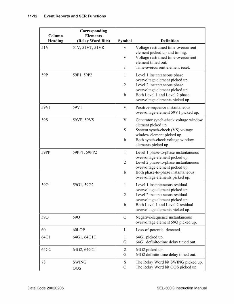
11-12 Event Reports and SER Functions
Date Code 20020206 SEL-300G Instruction Manual
Column Heading
Corresponding Elements
(Relay Word Bits) Symbol Definition 51V 51V, 51VT, 51VR v Voltage restrained time-overcurrent
element picked up and timing. V Voltage restrained time-overcurrent
element timed out. r Time-overcurrent element reset.
59P 59P1, 59P2 1 Level 1 instantaneous phase overvoltage element picked up.
2 Level 2 instantaneous phase overvoltage element picked up.
b Both Level 1 and Level 2 phase overvoltage elements picked up.
59V1 59V1 V Positive-sequence instantaneous overvoltage element 59V1 picked up.
59S 59VP, 59VS V Generator synch-check voltage window element picked up.
S System synch-check (VS) voltage window element picked up.
b Both synch-check voltage window elements picked up.
59PP 59PP1, 59PP2 1 Level 1 phase-to-phase instantaneous overvoltage element picked up.
2 Level 2 phase-to-phase instantaneous overvoltage element picked up.
b Both phase-to-phase instantaneous overvoltage elements picked up.
59G 59G1, 59G2 1 Level 1 instantaneous residual overvoltage element picked up.
2 Level 2 instantaneous residual overvoltage element picked up.
b Both Level 1 and Level 2 residual overvoltage elements picked up.
59Q 59Q Q Negative-sequence instantaneous overvoltage element 59Q picked up.
60 60LOP L Loss-of-potential detected.
64G1 64G1, 64G1T 1 64G1 picked up. G 64G1 definite-time delay timed out.
64G2 64G2, 64G2T 2 64G2 picked up. G 64G2 definite-time delay timed out.
78 SWING S The Relay Word bit SWING picked up. OOS O The Relay Word bit OOS picked up.
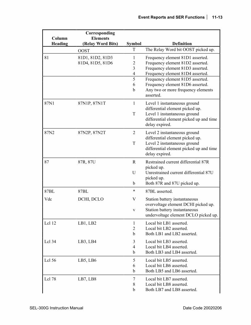
Event Reports and SER Functions 11-13
SEL-300G Instruction Manual Date Code 20020206
Column Heading
Corresponding Elements
(Relay Word Bits) Symbol Definition OOST T The Relay Word bit OOST picked up.
81 81D1, 81D2, 81D3 1 Frequency element 81D1 asserted. 81D4, 81D5, 81D6 2 Frequency element 81D2 asserted. 3 Frequency element 81D3 asserted. 4 Frequency element 81D4 asserted. 5 Frequency element 81D5 asserted. 6 Frequency element 81D6 asserted. b Any two or more frequency elements
asserted.
87N1 87N1P, 87N1T 1 Level 1 instantaneous ground differential element picked up.
T Level 1 instantaneous ground differential element picked up and time delay expired.
87N2 87N2P, 87N2T 2 Level 2 instantaneous ground differential element picked up.
T Level 2 instantaneous ground differential element picked up and time delay expired.
87 87R, 87U R Restrained current differential 87R picked up.
U Unrestrained current differential 87U picked up.
b Both 87R and 87U picked up.
87BL 87BL * 87BL asserted.
Vdc DCHI, DCLO V Station battery instantaneous overvoltage element DCHI picked up.
v Station battery instantaneous undervoltage element DCLO picked up.
Lcl 12 LB1, LB2 1 Local bit LB1 asserted. 2 Local bit LB2 asserted. b Both LB1 and LB2 asserted.
Lcl 34 LB3, LB4 3 Local bit LB3 asserted. 4 Local bit LB4 asserted. b Both LB3 and LB4 asserted.
Lcl 56 LB5, LB6 5 Local bit LB5 asserted. 6 Local bit LB6 asserted. b Both LB5 and LB6 asserted.
Lcl 78 LB7, LB8 7 Local bit LB7 asserted. 8 Local bit LB8 asserted. b Both LB7 and LB8 asserted.
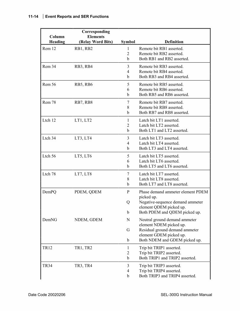
11-14 Event Reports and SER Functions
Date Code 20020206 SEL-300G Instruction Manual
Column Heading
Corresponding Elements
(Relay Word Bits) Symbol Definition Rem 12 RB1, RB2 1 Remote bit RB1 asserted. 2 Remote bit RB2 asserted. b Both RB1 and RB2 asserted.
Rem 34 RB3, RB4 3 Remote bit RB3 asserted. 4 Remote bit RB4 asserted. b Both RB3 and RB4 asserted.
Rem 56 RB5, RB6 5 Remote bit RB5 asserted. 6 Remote bit RB6 asserted. b Both RB5 and RB6 asserted.
Rem 78 RB7, RB8 7 Remote bit RB7 asserted. 8 Remote bit RB8 asserted. b Both RB7 and RB8 asserted.
Ltch 12 LT1, LT2 1 Latch bit LT1 asserted. 2 Latch bit LT2 asserted. b Both LT1 and LT2 asserted.
Ltch 34 LT3, LT4 3 Latch bit LT3 asserted. 4 Latch bit LT4 asserted. b Both LT3 and LT4 asserted.
Ltch 56 LT5, LT6 5 Latch bit LT5 asserted. 6 Latch bit LT6 asserted. b Both LT5 and LT6 asserted.
Ltch 78 LT7, LT8 7 Latch bit LT7 asserted. 8 Latch bit LT8 asserted. b Both LT7 and LT8 asserted.
DemPQ PDEM, QDEM P Phase demand ammeter element PDEM picked up.
Q Negative-sequence demand ammeter element QDEM picked up.
b Both PDEM and QDEM picked up.
DemNG NDEM, GDEM N Neutral ground demand ammeter element NDEM picked up.
G Residual ground demand ammeter element GDEM picked up.
b Both NDEM and GDEM picked up.
TR12 TR1, TR2 1 Trip bit TRIP1 asserted. 2 Trip bit TRIP2 asserted. b Both TRIP1 and TRIP2 asserted.
TR34 TR3, TR4 3 Trip bit TRIP3 asserted. 4 Trip bit TRIP4 asserted. b Both TRIP3 and TRIP4 asserted.
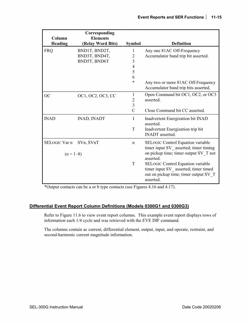
Event Reports and SER Functions 11-15
SEL-300G Instruction Manual Date Code 20020206
Column Heading
Corresponding Elements
(Relay Word Bits) Symbol Definition FRQ BND1T, BND2T,
BND3T, BND4T, BND5T, BND6T
1 2 3 4 5 6
Any one 81AC Off-Frequency Accumulator band trip bit asserted.
* Any two or more 81AC Off-Frequency Accumulator band trip bits asserted.
OC OC1, OC2, OC3, CC 1 2 3 C
Open Command bit OC1, OC2, or OC3 asserted. Close Command bit CC asserted.
INAD INAD, INADT I Inadvertent Energization bit INAD asserted.
T Inadvertent Energization trip bit INADT asserted.
SELOGIC Var n SVn, SVnT
(n = 18)
n
T
SELOGIC Control Equation variable timer input SV_ asserted; timer timing on pickup time; timer output SV_T not asserted. SELOGIC Control Equation variable timer input SV_ asserted; timer timed out on pickup time; timer output SV_T asserted.
*Output contacts can be a or b type contacts (see Figures 4.16 and 4.17).
Differential Event Report Column Definitions (Models 0300G1 and 0300G3)
Refer to Figure 11.6 to view event report columns. This example event report displays rows of information each 1/4 cycle and was retrieved with the EVE DIF command.
The columns contain ac current, differential element, output, input, and operate, restraint, and second-harmonic current magnitude information.
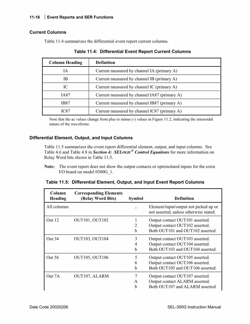
11-16 Event Reports and SER Functions
Date Code 20020206 SEL-300G Instruction Manual
Current Columns
Table 11.4 summarizes the differential event report current columns.
Table 11.4: Differential Event Report Current Columns
Column Heading Definition
IA Current measured by channel IA (primary A)
IB Current measured by channel IB (primary A)
IC Current measured by channel IC (primary A)
IA87 Current measured by channel IA87 (primary A)
IB87 Current measured by channel IB87 (primary A)
IC87 Current measured by channel IC87 (primary A)
Note that the ac values change from plus to minus (-) values in Figure 11.2, indicating the sinusoidal nature of the waveforms.
Differential Element, Output, and Input Columns
Table 11.5 summarizes the event report differential element, output, and input columns. See Table 4.6 and Table 4.8 in Section 4: SELOGIC® Control Equations for more information on Relay Word bits shown in Table 11.5.
Note: The event report does not show the output contacts or optoisolated inputs for the extra I/O board on model 0300G_1.
Table 11.5: Differential Element, Output, and Input Event Report Columns
Column Heading
Corresponding Elements(Relay Word Bits) Symbol Definition
All columns . Element/input/output not picked up or not asserted, unless otherwise stated.
Out 12 OUT101, OUT102 1 Output contact OUT101 asserted. 2 Output contact OUT102 asserted. b Both OUT101 and OUT102 asserted.
Out 34 OUT103, OUT104 3 Output contact OUT103 asserted. 4 Output contact OUT104 asserted. b Both OUT103 and OUT104 asserted.
Out 56 OUT105, OUT106 5 Output contact OUT105 asserted. 6 Output contact OUT106 asserted. b Both OUT105 and OUT106 asserted.
Out 7A OUT107, ALARM 7 Output contact OUT107 asserted. A Output contact ALARM asserted. b Both OUT107 and ALARM asserted.
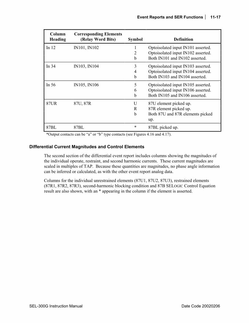
Event Reports and SER Functions 11-17
SEL-300G Instruction Manual Date Code 20020206
Column Heading
Corresponding Elements(Relay Word Bits) Symbol Definition
In 12 IN101, IN102 1 Optoisolated input IN101 asserted. 2 Optoisolated input IN102 asserted. b Both IN101 and IN102 asserted.
In 34 IN103, IN104 3 Optoisolated input IN103 asserted. 4 Optoisolated input IN104 asserted. b Both IN103 and IN104 asserted.
In 56 IN105, IN106 5 Optoisolated input IN105 asserted. 6 Optoisolated input IN106 asserted. b Both IN105 and IN106 asserted.
87UR 87U, 87R U 87U element picked up. R 87R element picked up. b Both 87U and 87R elements picked
up.
87BL 87BL * 87BL picked up. *Output contacts can be a or b type contacts (see Figures 4.16 and 4.17).
Differential Current Magnitudes and Control Elements
The second section of the differential event report includes columns showing the magnitudes of the individual operate, restraint, and second harmonic currents. These current magnitudes are scaled in multiples of TAP. Because these quantities are magnitudes, no phase angle information can be inferred or calculated, as with the other event report analog data.
Columns for the individual unrestrained elements (87U1, 87U2, 87U3), restrained elements (87R1, 87R2, 87R3), second-harmonic blocking condition and 87B SELOGIC Control Equation result are also shown, with an * appearing in the column if the element is asserted.

11-18 Event Reports and SER Functions
Date Code 20020206 SEL-300G Instruction Manual
SEQUENTIAL EVENTS RECORDER (SER) REPORT See Figure 11.5 for an example SER report.
SER Triggering
The relay triggers (generates) an entry in the SER report for a change of state of any one of the elements listed in the SER1, SER2, SER3, and SER4 trigger settings. The factory default settings are:
SER1 = 51NT 50N1T 51CT 51VT 64G1T 64G2T SV3 81D1 81D1T 81D2 81D2T 51N 50N1 51C 51V 64G1 64G2 INAD INADT
SER2 = DP3 LB1 RB1 LT3 TRGTR BCW IN101 IN102 TRIP1 TRIP2 TRIP3 TRIP4 BNDT 24C2T 32P1T 24C2 32P1 SV4 SV2T
SER3 = 24D1 24D1T 46Q1 46Q1T 60LOP BNDA 32P2 32P2T SWING OOS OOST SER4 = 0
The elements are Relay Word bits referenced in Table 4.6. The relay monitors each element in the SER lists every 1/4 cycle. If an element changes state, the relay time-tags the changes in the SER. For example, setting SER1 contains:
time-overcurrent element pickups (51N and 51C) instantaneous overcurrent element (50N1)
Thus, any time one of these overcurrent elements picks up or drops out, the relay time-tags the change in the SER.
The relay adds a message to the SER to indicate power up or settings change (to active setting group) conditions:
relay newly powered up or settings changed
Each entry in the SER includes SER row number, date, time, element name or defined alias, and element state.
Making SER Trigger Settings
Enter up to 24 element names in each of the SER settings via the SET R command. See Table 4.8 for references to valid relay element (Relay Word bit) names. See the SET R command in Table 6.1 and corresponding Settings Sheets at the end of Section 6: Enter Relay Settings. Use either spaces or commas to delimit the elements.
The relay can monitor up to 96 elements in the SER (24 in each of SER1, SER2, SER3, and SER4).
Retrieving SER Reports
The relay saves the latest 512 rows of the SER in nonvolatile memory. Row 1 is the most recently triggered row and Row 512 is the oldest. View the SER report by date or SER row number as outlined in the examples below.
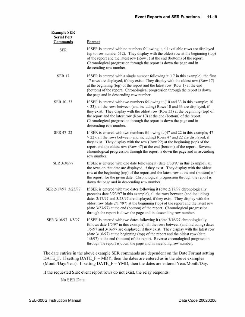
Event Reports and SER Functions 11-19
SEL-300G Instruction Manual Date Code 20020206
Example SER Serial Port Commands Format
SER If SER is entered with no numbers following it, all available rows are displayed (up to row number 512). They display with the oldest row at the beginning (top) of the report and the latest row (Row 1) at the end (bottom) of the report. Chronological progression through the report is down the page and in descending row number.
SER 17 If SER is entered with a single number following it (17 in this example), the first 17 rows are displayed, if they exist. They display with the oldest row (Row 17) at the beginning (top) of the report and the latest row (Row 1) at the end (bottom) of the report. Chronological progression through the report is down the page and in descending row number.
SER 10 33 If SER is entered with two numbers following it (10 and 33 in this example; 10 < 33), all the rows between (and including) Rows 10 and 33 are displayed, if they exist. They display with the oldest row (Row 33) at the beginning (top) of the report and the latest row (Row 10) at the end (bottom) of the report. Chronological progression through the report is down the page and in descending row number.
SER 47 22 If SER is entered with two numbers following it (47 and 22 in this example; 47 > 22), all the rows between (and including) Rows 47 and 22 are displayed, if they exist. They display with the row (Row 22) at the beginning (top) of the report and the oldest row (Row 47) at the end (bottom) of the report. Reverse chronological progression through the report is down the page and in ascending row number.
SER 3/30/97 If SER is entered with one date following it (date 3/30/97 in this example), all the rows on that date are displayed, if they exist. They display with the oldest row at the beginning (top) of the report and the latest row at the end (bottom) of the report, for the given date. Chronological progression through the report is down the page and in descending row number.
SER 2/17/97 3/23/97 If SER is entered with two dates following it (date 2/17/97 chronologically precedes date 3/23/97 in this example), all the rows between (and including) dates 2/17/97 and 3/23/97 are displayed, if they exist. They display with the oldest row (date 2/17/97) at the beginning (top) of the report and the latest row (date 3/23/97) at the end (bottom) of the report. Chronological progression through the report is down the page and in descending row number.
SER 3/16/97 1/5/97 If SER is entered with two dates following it (date 3/16/97 chronologically follows date 1/5/97 in this example), all the rows between (and including) dates 1/5/97 and 3/16/97 are displayed, if they exist. They display with the latest row (date 3/16/97) at the beginning (top) of the report and the oldest row (date 1/5/97) at the end (bottom) of the report. Reverse chronological progression through the report is down the page and in ascending row number.
The date entries in the above example SER commands are dependent on the Date Format setting DATE_F. If setting DATE_F = MDY, then the dates are entered as in the above examples (Month/Day/Year). If setting DATE_F = YMD, then the dates are entered Year/Month/Day.
If the requested SER event report rows do not exist, the relay responds:
No SER Data
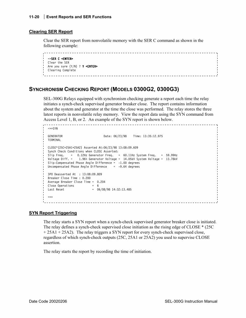
11-20 Event Reports and SER Functions
Date Code 20020206 SEL-300G Instruction Manual
Clearing SER Report
Clear the SER report from nonvolatile memory with the SER C command as shown in the following example:
=>SER C <ENTER>SER C <ENTER>SER C <ENTER>SER C <ENTER> Clear the SER Are you sure (Y/N) ? Y <ENTER>Y <ENTER>Y <ENTER>Y <ENTER> Clearing Complete
SYNCHRONISM CHECKING REPORT (MODELS 0300G2, 0300G3) SEL-300G Relays equipped with synchronism checking generate a report each time the relay initiates a synch-check supervised generator breaker close. The report contains information about the system and generator at the time the close was performed. The relay stores the three latest reports in nonvolatile relay memory. View the report data using the SYN command from Access Level 1, B, or 2. An example of the SYN report is shown below.
=>>SYN GENERATOR Date: 06/23/98 Time: 13:35:12.975 TERMINAL CLOSE*(25C+25A1+25A2) Asserted At:06/23/98 13:08:09.609 Synch Check Conditions when CLOSE Asserted: Slip Freq. = 0.12Hz Generator Freq. = 60.11Hz System Freq. = 59.99Hz Voltage Diff. = 1.96% Generator Voltage = 14.05kV System Voltage = 13.78kV Slip-Compensated Phase Angle Difference = -1.00 degrees Uncompensated Phase Angle Difference = -9.64 degrees 3PO Deasserted At : 13:08:09.809 Breaker Close Time : 0.200 Average Breaker Close Time = 0.204 Close Operations = 6 Last Reset = 06/08/98 14:32:13.485 =>>
SYN Report Triggering
The relay starts a SYN report when a synch-check supervised generator breaker close is initiated. The relay defines a synch-check supervised close initiation as the rising edge of CLOSE * (25C + 25A1 + 25A2). The relay triggers a SYN report for every synch-check supervised close, regardless of which synch-check outputs (25C, 25A1 or 25A2) you used to supervise CLOSE assertion.
The relay starts the report by recording the time of initiation.

Event Reports and SER Functions 11-21
SEL-300G Instruction Manual Date Code 20020206
Conditions When CLOSE Asserted
The SYN report shows the generator and system conditions at the time the CLOSE was initiated. Conditions displayed include present slip frequency, actual generator and system frequencies, percent voltage difference, and actual generator and system voltages.
Next, the slip-compensated and uncompensated phase angle differences are shown. The uncompensated phase angle difference is simply the phase angle between the system and generator voltages when CLOSE was inititiated. The relay calculates the slip-compensated phase angle difference using the equation:
Slip-Compensated Angle = Ang(VP) - Ang(VS) + (SLIPTCLOSD360) - COMPA
where
Ang(VP) = the generator voltage phase-angle, degrees
Ang(VS) = the system voltage phase-angle, degrees
SLIP = Present slip frequency, Hz
TCLOSD = breaker close time-delay setting, seconds
COMPA = delta-wye transformer compensation angle setting, degrees
The result of SLIPTCLOSD360°/cycle is the number of degrees that the generator voltage will travel with respect to the system voltage during the time that it takes the breaker to close (TCLOSD), assuming a constant slip frequency equal to SLIP.
When you supervise CLOSE initiation with the 25C Relay Word bit, the relay asserts 25C when the slip-compensated phase angle is approximately equal to the CANGLE setting. Thus, when you review a SYN report from a 25C supervised CLOSE, the slip-compensated angle should closely equal the CANGLE setting. The slip-compensated angle tells us what the relay expects the phase angle to be when the breaker actually closes TCLOSD seconds after CLOSE initiation.
SYN Report Closure
For the vast majority of breaker close operations, the breaker will close and the three-pole-open condition, 3PO, will deassert. If this occurs within about 99 seconds of CLOSE initiation, the relay records the time 3PO deasserted, calculates and displays the breaker close time, advances the close operation counter, and accounts for the new close time in the breaker close time average.
If the breaker does not close and slip is not close to 0 Hz, the generator voltage will rotate away from the system voltage until the phase angle exceeds the close-failure angle, CFANGL, setting. If this occurs within about 99 seconds of CLOSE initiation, the relay reports the message Close Failed in the place of the breaker close time and stores the SYN report.
If 3PO does not deassert and the uncompensated phase angle difference does not exceed the CFANGL setting within about 99 seconds of CLOSE initiation, the relay reports the message Close Failed in the place of the breaker close time and stores the SYN report.

11-22 Event Reports and SER Functions
Date Code 20020206 SEL-300G Instruction Manual
Use the Breaker Close Time Average
You can use the breaker close time average to refine the TCLOSD setting. By setting TCLOSD closer to the actual breaker closing time, the synch-check function performs better to cause a breaker close exactly when the generator voltage phase angle difference equals CANGLE.
Reset the Breaker Close Time Average
Use the Access Level 2 SYN R command to reset the Breaker Close Time Average and breaker close operations counter. The relay records the date and time of the last reset for inclusion in the SYN report.
EXAMPLE STANDARD 15-CYCLE EVENT REPORT The following example standard 15-cycle event report in Figure 11.2 (from a Model 0300G0 Relay) also corresponds to the example Sequential Events Recorder (SER) report in Figure 11.5. The circled numbers in Figure 11.2 correspond to the SER row numbers in Figure 11.5. The row explanations follow Figure 11.5.
In Figure 11.2, the arrow (>) in the column following the Freq column identifies the trigger row. This is the row that corresponds to the Date and Time values at the top of the event report.
The asterisk (*) in the column following the Freq column identifies the row with the maximum phase current. The maximum phase current is calculated from the row identified with the asterisk and the row one quarter-cycle previous (see Figure 11.3 and Figure 11.4). These currents are listed at the end of the event report in the event summary. If the trigger row (>) and the maximum phase current row (*) are the same row, the * symbol takes precedence.
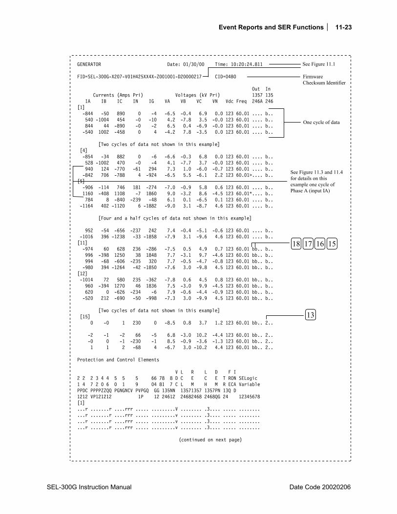
Event Reports and SER Functions 11-23
SEL-300G Instruction Manual Date Code 20020206
GENERATOR Date: 01/30/00 Time: 10:20:24.811 FID=SEL-300G-X207-V01H425XX4X-Z001001-D20000217 CID=04BO Out In Currents (Amps Pri) Voltages (kV Pri) 1357 135 IA IB IC IN IG VA VB VC VN Vdc Freq 246A 246 [1] -844 -50 890 0 -4 -6.5 -0.4 6.9 0.0 123 60.01 .... b.. 540 -1004 454 -0 -10 4.2 -7.8 3.5 -0.0 123 60.01 .... b.. 844 44 -890 -0 -2 6.5 0.4 -6.9 -0.0 123 60.01 .... b.. -540 1002 -458 0 4 -4.2 7.8 -3.5 0.0 123 60.01 .... b.. [Two cycles of data not shown in this example] [4] -854 -34 882 0 -6 -6.6 -0.3 6.8 0.0 123 60.01 .... b.. 528 -1002 470 -0 -4 4.1 -7.7 3.7 -0.0 123 60.01 .... b.. 940 124 -770 -61 294 7.3 1.0 -6.0 -0.7 123 60.01 .... b.. -842 706 -788 4 -924 -6.5 5.5 -6.1 2.2 123 60.01>.... b.. [5] -906 -114 746 181 -274 -7.0 -0.9 5.8 0.6 123 60.01 .... b.. 1160 -408 1108 -7 1860 9.0 -3.2 8.6 -4.5 123 60.01*.... b.. 784 8 -840 -239 -48 6.1 0.1 -6.5 0.1 123 60.01 .... b.. -1164 402 -1120 6 -1882 -9.0 3.1 -8.7 4.6 123 60.01 .... b.. [Four and a half cycles of data not shown in this example] 952 -54 -656 -237 242 7.4 -0.4 -5.1 -0.6 123 60.01 .... b.. -1016 396 -1238 -33 -1858 -7.9 3.1 -9.6 4.6 123 60.01 .... b.. [11] -974 60 628 236 -286 -7.5 0.5 4.9 0.7 123 60.01 bb.. b.. 996 -398 1250 38 1848 7.7 -3.1 9.7 -4.6 123 60.01 bb.. b.. 994 -68 -606 -235 320 7.7 -0.5 -4.7 -0.8 123 60.01 bb.. b.. -980 394 -1264 -42 -1850 -7.6 3.0 -9.8 4.5 123 60.01 bb.. b.. [12] -1014 72 580 235 -362 -7.8 0.6 4.5 0.8 123 60.01 bb.. b.. 960 -394 1270 46 1836 7.5 -3.0 9.9 -4.5 123 60.01 bb.. b.. 620 0 -626 -234 -6 7.9 -0.6 -4.4 -0.9 123 60.01 bb.. b.. -520 212 -690 -50 -998 -7.3 3.0 -9.9 4.5 123 60.01 bb.. b.. [Two cycles of data not shown in this example] [15] 0 -0 1 230 0 -8.5 0.8 3.7 1.2 123 60.01 bb.. 2.. -2 -1 -2 66 -5 6.8 -3.0 10.2 -4.4 123 60.01 bb.. 2.. -0 0 -1 -230 -1 8.5 -0.9 -3.6 -1.3 123 60.01 bb.. 2.. 1 1 2 -68 4 -6.7 3.0 -10.2 4.4 123 60.01 bb.. 2.. Protection and Control Elements V L R L D F I 2 2 2 3 4 4 5 5 5 66 78 8 D C E C E T RON SELogic 1 4 7 2 0 6 0 1 9 04 81 7 C L M H M R ECA Variable PPDC PPPPZZQQ PGNGNCV PVPGQ GG 135NN 13571357 1357PN 13Q D 1212 VP121212 1P 12 24612 24682468 2468QG 24 12345678 [1] ...r .......r ....rrr ..... .........V ........ .3.... ..... ........ ...r .......r ....rrr ..... .........v ........ .3.... ..... ........ ...r .......r ....rrr ..... .........v ........ .3.... ..... ........ ...r .......r ....rrr ..... .........v ........ .3.... ..... ........
(continued on next page)
See Figure 11.1
Firmware Checksum Identifier
One cycle of data
See Figure 11.3 and 11.4 for details on this example one cycle of Phase A (input IA)
17 18 1516
13

11-24 Event Reports and SER Functions
Date Code 20020206 SEL-300G Instruction Manual
(continued from previous page)
[Two cycles of data not shown in this example] [4] ...r .......r ....rrr ..... ........V ........ .3.... ..... ........ ...r .......r ....rrr ..... ........V ........ .3.... ..... ........ ...r .......r ..1.nrr ..... .1......V ........ .3.... ..... ........ ...r .......r ..1.nrr ..... .1......V ........ .3.... ..... ........> [5] ...r 1......r ..1.nrr ..... .1......V ........ .3.... ..... ........ ...r 1......r ..1.nrr ..... .1......V ........ .3.... ..... ........ ...r 1......r ..1.nrr ..... .1......V ........ .3.... ..... ........ ...r 1......r ..1.nrr ..... .1......V ........ .3.... ..... ........ [Four and a half cycles of data not shown in this example] ...r 1......r ..1.nrr ..... .1......V ........ .3.... ..... ........ ...r 1......r ..1.nrr ..... .1......V ........ .3.... bb... ..T..... [11] ...r 1......r ..1.nrr ..... .1......V ........ .3.... bb... ..T..... ...r 1......r ..1.nrr ..... .1......V ........ .3.... bb... ..T..... ...r 1......r ..1.nrr ..... .1......V ........ .3.... bb... ..T..... ...r 1......r ..1.nrr ..... .1......V ........ .3.... bb... ..T..... [12] ...r 1......r ..1.nrr ..... .1......V ........ .3.... bb... ..T..... ...r 1......r ..1.nrr ..... .1......V ........ .3.... bb... ..T..... ...r 1......r ..1.nrr ..... .1......V ........ .3.... bb... ..T..... ...r 1......r ..1.nrr ..... .1......V ........ .3.... bb... ..T..... [Two cycles of data not shown in this example] [15] ...r 1......r ..1.nrr ..... .1......V ........ .3.... bb... ..T..... ...r 1......r ..1.nrr ..... .1......V ........ .3.... bb... ..T..... ...r 1......r ..1.nrr ..... .1......V ........ .3.... bb... ..T..... ...r 1......r ..1.nrr ..... .1......V ........ .3.... bb... ..T..... Event: TRIG Frequency: 60.01 Targets: Currents (A Pri), ABCNGQ: 1471 424 1336 181 1880 112 Group 1 Settings: RID =GENERATOR TID =TERMINAL CTR = 100 CTRN = 100 PTR = 100 PTRN = 100 VNOM = 115.0 INOM = 5.0 EBUP = D E24 = Y E27 = Y E32 = Y E40 = Y E46 = Y E50 = Y E51 = Y E59 = N E64 = Y E78 = 1B E81 = 1 E81AC = 6 E87N = Y ESV = 6 ESL = 5 EDEM = ROL Z1R = 8.0 Z1O = 0.0 MTA1 = 88.0 Z1CMP = 0 Z1D = 0.00 Z2R = 16.0 Z2O = 0.0 MTA2 = 85.0 Z2CMP = 0 Z2D = 0.00 MPF = 0.80 MXLD = 1.2 21PTC =!3PO 24D1P = 105 24D1D = 1.00 24CCS = ID 24IP = 105 24IC = 2.0 24ITD = 0.1 24D2P2 = 176 24D2D2 = 3.00 24CR = 240.00 24TC =!60LOP
(continued on next page)
2022 21
1416 17 18 15
See Figure 11.1
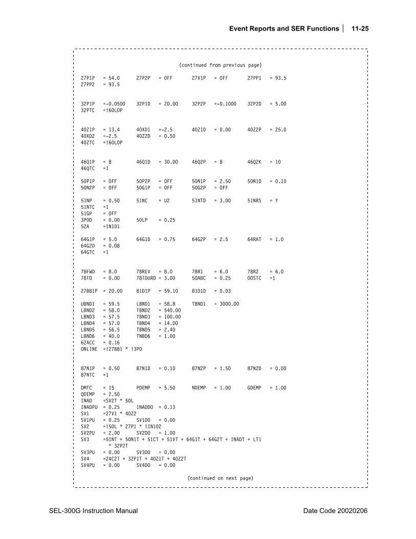
Event Reports and SER Functions 11-25
SEL-300G Instruction Manual Date Code 20020206
(continued from previous page)
27P1P = 54.0 27P2P = OFF 27V1P = OFF 27PP1 = 93.5 27PP2 = 93.5 32P1P =-0.0500 32P1D = 20.00 32P2P =-0.1000 32P2D = 5.00 32PTC =!60LOP 40Z1P = 13.4 40XD1 =-2.5 40Z1D = 0.00 40Z2P = 25.0 40XD2 =-2.5 40Z2D = 0.50 40ZTC =!60LOP 46Q1P = 8 46Q1D = 30.00 46Q2P = 8 46Q2K = 10 46QTC =1 50P1P = OFF 50P2P = OFF 50N1P = 2.50 50N1D = 0.10 50N2P = OFF 50G1P = OFF 50G2P = OFF 51NP = 0.50 51NC = U2 51NTD = 3.00 51NRS = Y 51NTC =1 51GP = OFF 3POD = 0.00 50LP = 0.25 52A =IN101 64G1P = 5.0 64G1D = 0.75 64G2P = 2.5 64RAT = 1.0 64G2D = 0.08 64GTC =1 78FWD = 8.0 78REV = 8.0 78R1 = 6.0 78R2 = 6.0 78TD = 0.00 78TDURD = 3.00 50ABC = 0.25 OOSTC =1 27B81P = 20.00 81D1P = 59.10 81D1D = 0.03 UBND1 = 59.5 LBND1 = 58.8 TBND1 = 3000.00 LBND2 = 58.0 TBND2 = 540.00 LBND3 = 57.5 TBND3 = 100.00 LBND4 = 57.0 TBND4 = 14.00 LBND5 = 56.5 TBND5 = 2.40 LBND6 = 40.0 TNBD6 = 1.00 62ACC = 0.16 ONLINE =!27B81 * !3PO 87N1P = 0.50 87N1D = 0.10 87N2P = 1.50 87N2D = 0.00 87NTC =1 DMTC = 15 PDEMP = 5.50 NDEMP = 1.00 GDEMP = 1.00 QDEMP = 2.50 INAD =SV2T * 50L INADPU = 0.25 INADDO = 0.13 SV1 =27V1 * 40Z2 SV1PU = 0.25 SV1DO = 0.00 SV2 =!50L * 27P1 * !IN102 SV2PU = 2.00 SV2DO = 1.00 SV3 =51NT + 50N1T + 51CT + 51VT + 64G1T + 64G2T + INADT + LT1 * 32P2T SV3PU = 0.00 SV3DO = 0.00 SV4 =24C2T + 32P1T + 40Z1T + 40Z2T SV4PU = 0.00 SV4DO = 0.00
(continued on next page)
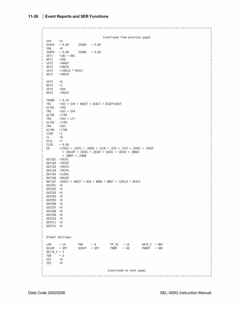
11-26 Event Reports and SER Functions
Date Code 20020206 SEL-300G Instruction Manual
(continued from previous page)
SV5 =0 SV5PU = 0.00 SV5DO = 0.00 SV6 =0 SV6PU = 0.00 SV6DO = 0.00 SET1 =LB1 + RB1 RST1 =3PO SET2 =INADT RST2 =TRGTR SET3 =!(DCLO * DCHI) RST3 =TRGTR SET4 =0 RST4 =1 SET5 =SV4 RST5 =TRGTR TDURD = 0.16 TR1 =SV3 + SV4 + 46Q2T + 81D1T + 81D2T+OOST ULTR1 =3PO TR2 =SV3 + SV4 ULTR2 =!TR2 TR3 =SV3 + LT1 ULTR3 =!TR3 TR4 =SV3 ULTR4 =!TR4 CLEN =1 CL =0 ULCL =1 CLSD = 0.00 ER =/24C2 + /32P1 + /46Q2 + /51N + /51C + /51V + /64G1 + /64G2 + /60LOP + /81D1 + /81D2 + \81D1 + \81D2 + /BNDA + /BNDT + /INAD OUT101 =TRIP1 OUT102 =TRIP2 OUT103 =TRIP3 OUT104 =TRIP4 OUT105 =CLOSE OUT106 =60LOP OUT107 =24D1T + 46Q1T + BCW + BNDA + BNDT + !(DCLO * DCHI) OUT201 =0 OUT202 =0 OUT203 =0 OUT204 =0 OUT205 =0 OUT206 =0 OUT207 =0 OUT208 =0 OUT209 =0 OUT210 =0 OUT211 =0 OUT212 =0 Global Settings: LER = 15 PRE = 4 FP_TO = 15 DATE_F = MDY DCLOP = OFF DCHIP = OFF FNOM = 60 PHROT = ABC DELTA_Y = Y TGR = 3 SS1 =0 SS2 =0
(continued on next page)

Event Reports and SER Functions 11-27
SEL-300G Instruction Manual Date Code 20020206
(continued from previous page) BKMON =TRIP COSP1 = 10000 COSP2 = 150 COSP3 = 12 KASP1 = 1.2 KASP2 = 8.0 KASP3 = 20.0 IN101D = 0.50 IN102D = 0.50 IN103D = 0.50 IN104D = 0.50 IN105D = 0.50 IN106D = 0.50 IN201D = 0.50 IN202D = 0.50 IN203D = 0.50 IN204D = 0.50 IN205D = 0.50 IN206D NLB1 =GEN SHUTDOWN CLB1 =RETURN SLB1 = PLB1 =TRIP NLB2 = NLB3 = NLB4 = NLB5 = NLB6 = NLB7 = NLB8 = NLB9 = NLB10 = NLB11 = NLB12 = NLB13 = NLB14 = NLB15 = NLB16 = FP_I = Y FP_VPP = Y FP_VP = N FP_MW = Y FP_FR = Y DP1 =IN101 DP1_1 =GEN BKR CLOSED DP1_0 =GEN BKR OPEN DP2 =IN102 DP2_1 =FIELD BKR CLOSED DP2_0 =FIELD BKR OPEN DP3 =SG1 DP3_1 =GROUP 1 ACTIVE DP3_0 =GROUP 2 ACTIVE DP4 =SV2T DP4_1 =INAD ARMED DP4_0 = DP5 =LT2 DP5_1 =INAD TRIP DP5_0 = DP6 =LT1 DP6_1 =SHUTDOWN TRIP DP6_0 = DP7 =LT5 DP7_1 =AB OP TRIP DP7_0 = DP8 =0 DP8_1 = DP8_0 = DP9 =0 DP9_1 = DP9_0 = DP10 =0 DP10_1 = DP10_0 = DP11 =0 DP11_1 = DP11_0 = DP12 =0 DP12_1 = DP12_0 = DP13 =0 DP13_1 = DP13_0 = DP14 =0 DP14_1 = DP14_0 = DP15 =0 DP15_1 = DP15_0 = DP16 =0 DP16_1 = DP16_0 = => =>
Figure 11.2: Example Standard 15-Cycle Event Report 1/4-Cycle Resolution

11-28 Event Reports and SER Functions
Date Code 20020206 SEL-300G Instruction Manual
Figure 11.3 and Figure 11.4 look in detail at 1 cycle of A-phase current (channel IA) identified in Figure 11.2. Figure 11.3 shows how the event report ac current column data relates to the actual sampled waveform and RMS values. Figure 11.4 shows how the event report current column data can be converted to phasor RMS values. Voltages are processed similarly.
DWG: M300G155
IA
event report column
(-842) +(-906)2 2
(-906) +(1160)2 2
(940) +(-842)2 2
940
-842
-906
1160
= 1262
= 1237
= 1472
2081 A peak =2
1472 A RMS
multiply by21
940
-842
-906
1160
multiply by21
1329
-119
0
-128
1
1640
IA peak = 2081 A peak
940-842
-9061160
IA
cyc14
t
Figure 11.3: Derivation of Event Report Current Values and RMS Current Values From Sampled Current Waveform
In Figure 11.3, note that any two rows of current data from the event report in Figure 11.2, 1/4 cycle apart, can be used to calculate RMS current values.
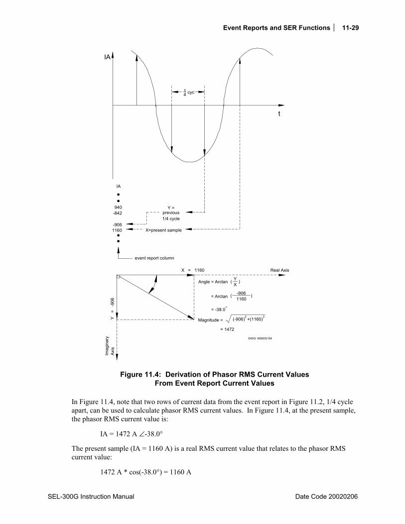
Event Reports and SER Functions 11-29
SEL-300G Instruction Manual Date Code 20020206
IA
940-842
-9061160
event report column
DWG: M300G154
(-906) +(1160)2 2
= 1472
X=present sample
Y =previous1/4 cycle
Magnitude =
X = 1160
Y =
-9
06
)
Real Axis
Axis
Imag
inar
y
Angle = Arctan
= Arctan
YX
( )
(
= -38.0o
-9061160
IA
cyc14
t
Figure 11.4: Derivation of Phasor RMS Current Values From Event Report Current Values
In Figure 11.4, note that two rows of current data from the event report in Figure 11.2, 1/4 cycle apart, can be used to calculate phasor RMS current values. In Figure 11.4, at the present sample, the phasor RMS current value is:
IA = 1472 A ∠-38.0°
The present sample (IA = 1160 A) is a real RMS current value that relates to the phasor RMS current value:
1472 A * cos(-38.0°) = 1160 A

11-30 Event Reports and SER Functions
Date Code 20020206 SEL-300G Instruction Manual
EXAMPLE SEQUENTIAL EVENTS RECORDER (SER) REPORT The following example SER report in Figure 11.5 (from a Model 0300G0 relay) also corresponds to the example standard 15-cycle event report in Figure 11.2.
GENERATOR Date: 01/30/00 Time: 10:20:45.872 TERMINAL FID=SEL-300G-X207-V31H425XX4X-Z001001-D200000217 CID=04B0 # DATE TIME ELEMENT STATE 22 01/20/98 09:09:58.611 51N Asserted 21 01/20/98 09:09:58.611 64G1 Asserted 20 01/20/98 09:09:58.611 50N1 Asserted 19 01/20/98 09:09:58.714 50N1T Asserted 18 01/20/98 09:09:58.714 86_TRIP TRIPPED 17 01/20/98 09:09:58.714 PRIME_MVR_TR TRIPPED 16 01/20/98 09:09:58.714 FIELD_BKR_TR TRIPPED 15 01/20/98 09:09:58.714 GEN_MAIN_TR TRIPPED 14 01/20/98 09:09:58.714 FAULT_TRIP TRIPPED 13 01/20/98 09:09:58.760 GEN_MAIN_BKR OPENED 12 01/20/98 09:09:58.810 60LOP Asserted 11 01/20/98 09:09:58.826 51N Deasserted 10 01/20/98 09:09:58.826 50N1T Deasserted 9 01/20/98 09:09:58.826 50N1 Deasserted 8 01/20/98 09:09:58.826 FAULT_TRIP RESET 7 01/20/98 09:09:58.826 FIELD_BKR OPENED 6 01/20/98 09:09:58.830 64G1 Deasserted 5 01/20/98 09:09:58.876 86_TRIP RESET 4 01/20/98 09:09:58.876 PRIME_MVR_TR RESET 3 01/20/98 09:09:58.876 FIELD_BKR_TR RESET 2 01/20/98 09:09:58.876 GEN_MAIN_TR RESET 1 01/20/98 09:10:00.828 INAV_ENR_SCHM ARMED
Figure 11.5: Example Sequential Events Recorder (SER) Event Report
The SER event report rows in Figure 11.5 are explained in the following text, numbered in correspondence to the # column. The circled, numbered comments in Figure 11.2 also correspond to the # column numbers in Figure 11.5. The SER event report in Figure 11.5 contains records of events that occurred after the standard event report in Figure 11.2.
Item # Explanation
22, 21, 20 Neutral time-overcurrent element, 51N, 100% stator ground element, 64G1, and neutral definite-time overcurrent element, 50N1, pick up and start timing at fault inception.
19 50N1D definite time-delay expires and 50N1T Relay Word bit asserts. Related settings: 50N1D = 0.10 seconds Time difference: 09:09:58.714 09:09:58.611 = 0.103 seconds
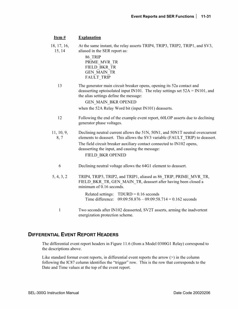
Event Reports and SER Functions 11-31
SEL-300G Instruction Manual Date Code 20020206
Item # Explanation
18, 17, 16, 15, 14
At the same instant, the relay asserts TRIP4, TRIP3, TRIP2, TRIP1, and SV3, aliased in the SER report as:
86_TRIP PRIME_MVR_TR FIELD_BKR_TR GEN_MAIN_TR FAULT_TRIP
13 The generator main circuit breaker opens, opening its 52a contact and deasserting optoisolated input IN101. The relay settings set 52A = IN101, and the alias settings define the message:
GEN_MAIN_BKR OPENED when the 52A Relay Word bit (input IN101) deasserts.
12 Following the end of the example event report, 60LOP asserts due to declining generator phase voltages.
11, 10, 9, 8, 7
Declining neutral current allows the 51N, 50N1, and 50N1T neutral overcurrent elements to deassert. This allows the SV3 variable (FAULT_TRIP) to deassert. The field circuit breaker auxiliary contact connected to IN102 opens, deasserting the input, and causing the message:
FIELD_BKR OPENED
6 Declining neutral voltage allows the 64G1 element to deassert.
5, 4, 3, 2 TRIP4, TRIP3, TRIP2, and TRIP1, aliased as 86_TRIP, PRIME_MVR_TR, FIELD_BKR_TR, GEN_MAIN_TR, deassert after having been closed a minimum of 0.16 seconds.
Related settings: TDURD = 0.16 seconds Time difference: 09:09:58.876 09:09:58.714 = 0.162 seconds
1 Two seconds after IN102 deasserted, SV2T asserts, arming the inadvertent energization protection scheme.
DIFFERENTIAL EVENT REPORT HEADERS The differential event report headers in Figure 11.6 (from a Model 0300G1 Relay) correspond to the descriptions above.
Like standard format event reports, in differential event reports the arrow (>) in the column following the IC87 column identifies the trigger row. This is the row that corresponds to the Date and Time values at the top of the event report.

11-32 Event Reports and SER Functions
Date Code 20020206 SEL-300G Instruction Manual
The asterisk (*) in the column following the IC87 column identifies the row with the maximum phase current. The maximum phase current is calculated from the row identified with the asterisk and the row 1 quarter-cycle previous. These currents are listed at the end of the event report in the event summary. If the trigger row (>) and the maximum phase current row (*) are the same row, the * symbol takes precedence.
GENERATOR Date: 01/30/00 Time: 10:20:01.350 TERMINAL FID=SEL-300G-X207-V31H425XX4X-Z001001-D20000217 CID=04B0 8 7 Out In Currents (Amps Pri) UB 1357 135 IA IB IC IA87 IB87 IC87 RL 246A 246 [1] 488 -1824 1332 -486 1823 -1333 .. ...7 ... 1820 -488 -1333 -1816 488 1334 *.. ...7 ... -488 1824 -1332 487 -1823 1334 .. ...7 ... -1821 488 1333 1816 -488 -1334 .. ...7 ... [2] . . . Differential Current Magnitudes and Control Elements 8 8 8 Operate Restraint 2nd Harm 7 7 7 8 (Multiples of TAP) U R B 7 I1 I2 I3 I1 I2 I3 I1 I2 I3 123 123 123 B [1] 0.00 0.00 0.00 0.94 0.95 0.94 0.01 0.00 0.00 ... ... ... . 0.00 0.01 0.00 0.94 0.95 0.94 0.00 0.00 0.00*... ... ... . 0.00 0.00 0.00 0.94 0.95 0.94 0.00 0.00 0.00 ... ... ... . 0.00 0.00 0.00 0.94 0.95 0.94 0.00 0.00 0.00 ... ... ... . [2] Event: TRIG Frequency: 60.00 Targets: Currents (A Pri), ABCNGQ: 1885 1888 1884 1 1 0 Group 1 Settings: RID =GENERATOR TID =TERMINAL . . .
Figure 11.6: Example Differential Event Report 1/4-Cycle Resolution
SEL-300G Instruction Manual Date Code 20010615
TABLE OF CONTENTS
SECTION 12: MAINTAIN AND TROUBLESHOOT RELAY...................12-1 Relay Maintenance Testing.........................................................................................................12-1 Relay Misoperation .....................................................................................................................12-2 Relay Troubleshooting................................................................................................................12-3
Inspection Procedure ...........................................................................................................12-3 Troubleshooting Procedure .................................................................................................12-3
All Front-Panel LEDs Dark.........................................................................................12-3 Cannot See Characters on Relay LCD Screen ............................................................12-3 Relay Does Not Respond to Commands From Device Connected to Serial Port .......12-4 Relay Does Not Respond to Faults..............................................................................12-4
Relay Calibration ........................................................................................................................12-4 Firmware (FLASH) Upgrade Instructions ..................................................................................12-4
Required Equipment............................................................................................................12-4 Upgrade Instructions ...........................................................................................................12-5
Factory Assistance ......................................................................................................................12-8


Maintain and Troubleshoot Relay 12-1
SEL-300G Instruction Manual Date Code 20000616
SECTION 12: MAINTAIN AND TROUBLESHOOT RELAY
RELAY MAINTENANCE TESTING The maintenance testing philosophy for SEL relays is very simple. Our recommendations are summarized below:
a) Monitor the relay self-test ALARM contact to ensure that relay problems detected by the relay itself are quickly noticed and corrected.
b) Review relay generated event reports and SER records following each operation to ensure that relay and connection equipment performance is nominal.
c) Periodically check relay METER data for sensibility. d) Periodically perform relay I/O operation checks.
SEL relays use extensive self-testing capabilities that detect and indicate relay problems when they occur. By monitoring the relay ALARM contact, you are immediately notified when the relay is out of service and can take appropriate steps to diagnose and correct the problem. Relay functions such as the dc monitor function and loss-of-potential function should also be used to alarm for abnormal conditions and failures that can be detrimental to the protection system performance if not immediately corrected.
SEL relay reporting functions such as event reports and SER records can quickly indicate problems with the relay and other connected equipment. Using the event report current, voltage, and relay element data, you can determine that the relay protection elements are operating properly. Using the event report input and output data, you can determine that the relay is asserting outputs at the correct instants and that auxiliary equipment is operating properly. We recommend you review all relay event reports and perform detailed reviews of reports for operations that are not nominal.
Periodically verify that the relay is making correct and accurate current and voltage measurements by comparing the relay METER output to other meter readings on the protected generator. Often, simple sensibility checks are sufficient to indicate a serious problem. Relay calibration can be verified by comparing the relay METER readings to the readings of a calibrated meter in the same circuit. Due to the hardware design of this relay, typically, the relay accuracy will not drift gradually, but rather will be obviously erroneous if there is a problem with the relay data acquisition system.
To verify correct operation of relay output contacts, perform the following steps:
1. Isolate the relay output contacts from their dc circuits.
2. Using the Access Level B PULSE command or the front-panel CNTRL function, close the relay output contacts individually (see Section 9: Front-Panel Operation and Section 10: Serial Port Communications and Commands for more detailed information regarding use of the contact control functions).
12-2 Maintain and Troubleshoot Relay
Date Code 20000616 SEL-300G Instruction Manual
3. Use a continuity tester to verify that the relay contact closes when commanded.
4. Return the relay contacts to service in their individual circuits. Perform any additional desired tests to verify the circuit performance.
To verify correct operation of relay optoisolated inputs, perform the following steps:
1. Isolate the relay optoisolated inputs from their dc circuits.
2. Using the Access Level 1 TAR command or the front-panel TAR function, monitor the state of the optoisolated inputs individually while you apply rated dc control voltage to the rear-panel terminals for each input (see Section 9: Front-Panel Operation and Section 10: Serial Port Communications and Commands for more detailed information regarding use of the contact control functions).
3. Return the relay optoisolated inputs to service in their individual circuits. Perform any additional desired tests to verify the circuit performance.
These tests do not need to be performed more frequently than your present protection maintenance interval. Two- to five-year intervals are acceptable, particularly if relay event reports are reviewed as suggested above.
RELAY MISOPERATION In the unlikely event of a relay misoperation, perform the following steps as soon as it is safe and practical to do so:
1. Do not remove dc power from the relay. If desired, you may isolate the relay contact outputs.
2. On a sheet of paper, record the state of the front-panel target LEDs. Also record the contents of rotating display messages from the front-panel LCD display.
3. Press the front-panel STATUS pushbutton. If the relay STATUS is OK, continue with Step 4. If STATUS indicates a WARN or FAIL condition, use the Up and Down arrow pushbuttons and note the failed self-test condition. Contact the factory or your local Technical Service Center for assistance.
4. Using a PC, establish Access Level 1 communication with the relay. Using your terminal emulation software text capture facility, open an ASCII text file on your PC disk drive to record relay data.
5. With the text file open, execute the relay HISTORY command. With the relay response on the PC screen, note the relay event report numbers associated with the date and time of the misoperation. If the operation involves optional current differential elements, record the differential formal event report using EVE Diff n. Use the EVE n command to view and store the event reports of interest. Use the SER command to view and store the relay sequence of events record for the misoperation. Use the SHO R command to record the active SER settings. Close the text file. Section 10: Serial Port Communications and Commands contains information on establishing serial communications with the relay and more details on the commands above.
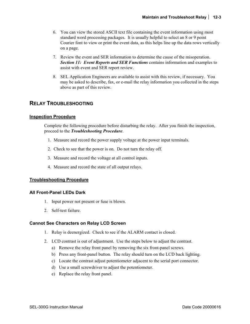
Maintain and Troubleshoot Relay 12-3
SEL-300G Instruction Manual Date Code 20000616
6. You can view the stored ASCII text file containing the event information using most standard word processing packages. It is usually helpful to select an 8 or 9 point Courier font to view or print the event data, as this helps line up the data rows vertically on a page.
7. Review the event and SER information to determine the cause of the misoperation. Section 11: Event Reports and SER Functions contains information and examples to assist with event and SER report review.
8. SEL Application Engineers are available to assist with this review, if necessary. You may be asked to describe, fax, or e-mail the relay information you collected in the steps above as part of this review.
RELAY TROUBLESHOOTING
Inspection Procedure
Complete the following procedure before disturbing the relay. After you finish the inspection, proceed to the Troubleshooting Procedure.
1. Measure and record the power supply voltage at the power input terminals.
2. Check to see that the power is on. Do not turn the relay off.
3. Measure and record the voltage at all control inputs.
4. Measure and record the state of all output relays.
Troubleshooting Procedure
All Front-Panel LEDs Dark
1. Input power not present or fuse is blown.
2. Self-test failure.
Cannot See Characters on Relay LCD Screen
1. Relay is deenergized. Check to see if the ALARM contact is closed.
2. LCD contrast is out of adjustment. Use the steps below to adjust the contrast. a) Remove the relay front panel by removing the six front-panel screws. b) Press any front-panel button. The relay should turn on the LCD back lighting. c) Locate the contrast adjust potentiometer adjacent to the serial port connector. d) Use a small screwdriver to adjust the potentiometer. e) Replace the relay front panel.

12-4 Maintain and Troubleshoot Relay
Date Code 20000616 SEL-300G Instruction Manual
Relay Does Not Respond to Commands From Device Connected to Serial Port
1. Communications device not connected to relay.
2. Relay or communications device at incorrect baud rate or other communication parameter incompatibility, including cabling error.
3. Relay serial port has received an XOFF, halting communications. Type <CTRL>Q to send the relay an XON and restart communications.
Relay Does Not Respond to Faults
1. Relay improperly set.
2. Improper test source settings.
3. CT or PT input wiring error.
4. Analog input cable between transformer secondary and main board loose or defective.
5. Failed relay self-test.
RELAY CALIBRATION The SEL-300G Relay is factory-calibrated. If you suspect that the relay is out of calibration, please contact the factory.
FIRMWARE (FLASH) UPGRADE INSTRUCTIONS SEL may occasionally offer firmware upgrades to improve the performance of your relay. The SEL-300G Relay stores firmware in FLASH memory; therefore, changing physical components is not necessary. Upgrade the relay firmware by downloading a file from a personal computer to the relay via a serial port as outlined in the following sections.
Required Equipment
• Personal computer. • Terminal emulation software that supports XMODEM/CRC protocol (e.g., Procomm Plus,
Relay/Gold, Microsoft® Windows® Terminal, SmartCOM, and CROSSTALK®. • Serial communications cable (SEL-C234A or equivalent). • Disk containing firmware upgrade file.

Maintain and Troubleshoot Relay 12-5
SEL-300G Instruction Manual Date Code 20000616
Upgrade Instructions
The instructions below assume you have a working knowledge of your personal computer terminal emulation software. In particular, you must be able to modify your serial communications parameters (baud rate, data bits, parity, etc.), select transfer protocol (i.e., XMODEM/CRC), and transfer files (e.g., send and receive binary files).
1. If the relay is in service, open its trip and close circuits.
2. Connect the personal computer to the relay Serial Port 2 or 3 and enter Access Level 2.
3. If you do not already have copies of the Relay, Global, Port, and SER settings, issue the following commands to retrieve the settings: SHO 1, SHO 2, SHO G, SHO P 1, SHO P 2, SHO P 3, SHO P F, and SHO R.
Normally, the relay will preserve the settings during the firmware upgrade. However, if the new firmware version includes more settings than the old version, you will have to reenter your old settings.
4. Set up your communication connection to the highest possible baud rate. The relay will support speeds up to 38400 baud. Use the SET P command to change the SPEED setting to the desired baud rate.
5. Issue the L_D <ENTER> command to the relay (L underscore D ENTER).
6. Type Y <ENTER> to the Disable relay to send or receive firmware(Y/N)? prompt and Y <ENTER> to the Are you sure (Y/N)? prompt. The relay will send the SELBOOT prompt !>.
7. Make a copy of the firmware currently in the relay. This is recommended in case the new firmware download is unsuccessful. To make a backup of the firmware, you will need approximately 2.3 MB of free disk space. The procedure takes approximately 10 minutes at 38400 baud.
Issue the SEN <ENTER> command to initiate the firmware transfer. Select the binary XMODEM transfer and filename in your communications software. Give the file a unique name to clearly identify the firmware version (e.g., 300GR100.S19). After the transfer, the relay will respond: Download completed successfully!
8. Transfer the new firmware to the relay. Issue the REC <ENTER> command to instruct the relay to receive new firmware.
9. Type Y to erase the existing firmware or just <ENTER> to abort.
10. The relay then prompts you to press a key and begin the transfer. Press a key (e.g., <ENTER>).
11. Start the file transfer by selecting the send file option in your communication software. Use the XMODEM protocol and send the file that contains the new firmware (e.g., 300GR101.S19).
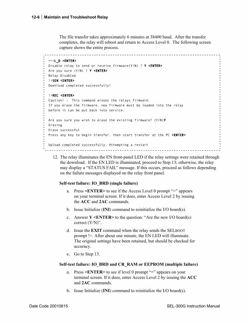
12-6 Maintain and Troubleshoot Relay
Date Code 20010615 SEL-300G Instruction Manual
The file transfer takes approximately 6 minutes at 38400 baud. After the transfer completes, the relay will reboot and return to Access Level 0. The following screen capture shows the entire process.
=>>L_D <ENTER>L_D <ENTER>L_D <ENTER>L_D <ENTER> Disable relay to send or receive firmware(Y/N) ? Y <ENTER>Y <ENTER>Y <ENTER>Y <ENTER> Are you sure (Y/N) ? Y <ENTER>Y <ENTER>Y <ENTER>Y <ENTER> Relay Disabled !>SEN <ENTER>SEN <ENTER>SEN <ENTER>SEN <ENTER> Download completed successfully! !>REC <ENTER>REC <ENTER>REC <ENTER>REC <ENTER> Caution! - This command erases the relays firmware. If you erase the firmware, new firmware must be loaded into the relay before it can be put back into service. Are you sure you wish to erase the existing firmware? (Y/N)YYYY Erasing Erase successful Press any key to begin transfer, then start transfer at the PC <ENTER> <ENTER> <ENTER> <ENTER> Upload completed successfully. Attempting a restart
12. The relay illuminates the EN front-panel LED if the relay settings were retained through the download. If the EN LED is illuminated, proceed to Step 13; otherwise, the relay may display a STATUS FAIL message. If this occurs, proceed as follows depending on the failure messages displayed on the relay front panel.
Self-test failure: IO_BRD (single failure)
a. Press <ENTER> to see if the Access Level 0 prompt = appears on your terminal screen. If it does, enter Access Level 2 by issuing the ACC and 2AC commands.
b. Issue Initialize (INI) command to reinitialize the I/O board(s).
c. Answer Y <ENTER> to the question: Are the new I/O board(s) correct (Y/N).
d. Issue the EXIT command when the relay sends the SELBOOT prompt !>. After about one minute, the EN LED will illuminate. The original settings have been retained, but should be checked for accuracy.
e. Go to Step 13.
Self-test failure: IO_BRD and CR_RAM or EEPROM (multiple failure)
a. Press <ENTER> to see if level 0 prompt = appears on your terminal screen. If it does, enter Access Level 2 by issuing the ACC and 2AC commands.
b. Issue Initialize (INI) command to reinitialize the I/O board(s).

Maintain and Troubleshoot Relay 12-7
SEL-300G Instruction Manual Date Code 20010615
c. Answer Y <ENTER> to the question: Are the new I/O board(s) correct (Y/N).
d. Issue the EXIT command when the relay sends the SELBOOT prompt !>.
e. Set your communications software settings to 2400 baud, 8 data bits, 1 stop bit.
f. Enter Access Level 2 by issuing the ACC and 2AC commands.
g. Issue the R_S command to restore the factory default settings in the relay. The relay will then reboot with the factory default settings.
h. If the message, Calibration settings lost, please call the factory! appears during the restart, please contact the factory using the information in the back of this section.
i. Enter Access Level 2.
j. Issue a STA command and verify the relay status is OK.
k. Set the Relay, Global, and SER settings with each of the following commands: SET 1, SET 2, SET G, SET P 1, SET P 2, SET P 3, SET P F, SET R.
l. Set the relay passwords via the PAS command.
m. Go to Step 13.
Self-test failure: CR_RAM and/or EEPROM
a. Set your communications software settings to 2400 baud, 8 data bits, 1 stop bit.
b. Enter Access Level 2 by issuing the ACC and 2AC commands.
c. Issue the R_S command to restore the factory default settings in the relay. The relay will then reboot with the factory default settings.
d. If the message, Calibration settings lost, please call the factory! appears during the restart, please contact the factory using the information in the back of this section.
e. Enter Access Level 2.
f. Issue a STA command and verify the relay status is OK.
g. Set the Relay, Global, and SER settings with each of the following commands: SET 1, SET 2, SET G, SET P 1, SET P 2, SET P 3, SET P F, SET R.
h. Set the relay passwords via the PAS command.
13. Execute the STATUS command to verify all relay self-test parameters are within tolerance.
14. Apply current and voltage signals to the relay. Issue the METER command; verify the current and voltage signals are correct. Issue the TRIGGER and EVENT commands. Verify the current and voltage signals are correct in the EVENT report.

12-8 Maintain and Troubleshoot Relay
Date Code 20010615 SEL-300G Instruction Manual
15. If an SEL-2020 or SEL-2030 Communications Processor is connected to the SEL-300G Relay, re-auto-configure the SEL-20x0 port. This step will prevent a future auto-configuration failure of the SEL-20x0 when its power is cycled and if the new SEL-300G Relay firmware does not match the original configuration.
The relay is now ready for your commissioning procedure.
FACTORY ASSISTANCE The employee-owners of Schweitzer Engineering Laboratories are dedicated to making electric power safer, more reliable, and more economical.
We appreciate your interest in SEL products, and we are committed to making sure you are satisfied. If you have any questions, please contact us at:
Schweitzer Engineering Laboratories 2350 NE Hopkins Court Pullman, WA USA 99163-5603 Tel: (509) 332-1890 Fax: (509) 332-7990
We guarantee prompt, courteous, and professional service.
We appreciate receiving any comments and suggestions about new products or product improvements that would help us make your job easier.
SEL-300G Instruction Manual Date Code 20020206
TABLE OF CONTENTS
SECTION 13: DIFFERENTIAL ELEMENT SETTINGS .......................13-1
Introduction .................................................................................................................................13-1 Ground Differential Element (Models 0300G0 and 0300G2) ....................................................13-1
Element Description............................................................................................................13-1 Functional Description ................................................................................................13-1 Setting Descriptions ....................................................................................................13-2 Relay Word Bits ..........................................................................................................13-2
Setting Calculation ..............................................................................................................13-3 Information Needed.....................................................................................................13-3 Recommendations .......................................................................................................13-3 Ground Differential Element Tripping........................................................................13-3
Element Operating Characteristics......................................................................................13-3 Percentage Restrained Differential Element Overview (Models 0300G1 and 300G3) ..............13-4
Relay Word Bits ..........................................................................................................13-7 Settings For Generator Protection...............................................................................................13-8
Setting Description..............................................................................................................13-8 Setting Calculation ..............................................................................................................13-9
Unrestrained Differential Element Pickup Setting, U87P...........................................13-9 Restrained Differential Element Pickup Setting, O87P ............................................13-10 Restrained Differential Element Slope 1 Setting, SLP1 ...........................................13-10 Fixed Settings: SLP2, IRS1, PCT2...........................................................................13-10 Derived Settings: TAP1, TAPD ...............................................................................13-10 Differential Element Tripping...................................................................................13-11
Settings For Unit Protection......................................................................................................13-11 Setting Description............................................................................................................13-11 Setting Calculation ............................................................................................................13-13
Transformer High-Side Line-to-Line Voltage, VWDGD .........................................13-13 Transformer and CT Connection Settings, TRCON and CTCON............................13-13 Derived Tap Settings, TAP1, TAPD .........................................................................13-13 Unrestrained Differential Element Pickup Setting, U87P.........................................13-14 Restrained Differential Element Pickup Setting, O87P ............................................13-14 Percentage Restraint Slope 2 Settings, SLP2, IRS1..................................................13-15 Second-Harmonic Blocking Settings, PCT2, IHBL..................................................13-15 Differential Element Tripping...................................................................................13-15
Differential Element Transformer Connection and Ratio Compensation.................................13-16 Restrained Differential Element Operating Characteristics......................................................13-17
TABLES Table 13.1: Connection and TAP Compensation..................................................................................13-16

ii Differential Element Settings
Date Code 20020206 SEL-300G Instruction Manual
FIGURES Figure 13.1: 87N Element Logic Diagram..............................................................................................13-3 Figure 13.2: Fundamental and Second-Harmonic Filters Provide Current Inputs to Differential
Elements .......................................................................................................................13-4 Figure 13.3: Operate, Restraint, and Second-Harmonic Blocking Current Calculations .......................13-5 Figure 13.4: Differential Element Logic Diagram..................................................................................13-6 Figure 13.5: Restrained Differential Element Logic When E87 = G......................................................13-6 Figure 13.6: Restrained Differential Element Logic When E87 = T and IHBL = N..............................13-7 Figure 13.7: Restrained Differential Element Logic When E87 = T and IHBL = Y..............................13-7 Figure 13.8: Differential Element Operating Characteristics ...............................................................13-17
Differential Element Settings 13-1
SEL-300G Instruction Manual Date Code 20020206
SECTION 13: DIFFERENTIAL ELEMENT SETTINGS
INTRODUCTION The SEL-300G1/300G3 Relays are equipped with differential current inputs. These relays use these current inputs to operate nondedicated phase, negative-sequence, and residual overcurrent elements, described in Section 2: Relay Element Settings. These relays also use these inputs to develop percentage restrained phase current differential elements, whose operation and settings are described in this section.
The SEL-300G0/300G2 Relays are not equipped with differential current inputs, but provide a ground current differential element (87N) that operates based on the difference between the measured neutral current and the sum of the three phase current inputs. The 87N element provides sensitive ground fault detection on resistance-grounded and solidly grounded generators, particularly where multiple generators are connected directly to a load bus. This element should not be applied to protect high-impedance grounded generators.
GROUND DIFFERENTIAL ELEMENT (MODELS 0300G0 AND 0300G2)
Element Description
Functional Description
The SEL-300G0/300G2 Relays provide two definite-time delayed ground current differential elements designed to detect ground faults on resistance grounded and solidly grounded generators. Because these elements are current-based, they cannot provide ground fault coverage for 100% of the stator windings. They do, however, offer selective ground fault protection because they do not respond to ground faults beyond the generator phase current transformers. This quality makes the element well suited to protect generators connected to multiple-unit buses, or for generators connected to a load-bus, such as might be found in an industrial installation.
The relay measures the generator neutral current using the neutral CT connected to the relay IN input. It then calculates the residual current, which is the sum of the three phase current inputs. The residual current is adjusted by the ratio of the CTR and CTRN settings to scale the residual current in terms of the secondary neutral current, then the difference is calculated. Normally, under balanced load or external ground fault conditions, the difference current should be zero. In the event of an internal ground fault, the difference current will be nonzero. If the difference current magnitude is greater than the element pickup setting, the element picks up and begins to operate the definite time-delay. If the difference current remains above the pickup setting for the duration of the definite time-delay, the time-delayed element Relay Word bit asserts.
Note: The 87N elements are applicable only when the generator and relay are connected as shown in Figures 5.16 or 5.17. Do not attempt to use this element with high-impedance grounded generators, as the primary residual current they supply during a ground fault is too low for secure, dependable protection.
13-2 Differential Element Settings
Date Code 20020206 SEL-300G Instruction Manual
Setting Descriptions Enable Ground Differential Protection (Y,N) E87N = Y
Set E87N = Y to enable ground differential elements. If ground differential protection is not required, set E87N = N. When E87N = N, the 87N1P, 87N1T, 87N2P, and 87N2T Relay Word bits are inactive and the following relay settings are hidden and do not need to be entered.
Level 1 Ground Differential Pickup (0.1 CTR/CTRN15 A, 5 A models) 87N1P = 0.5 (0.02 CTR/CTRN3 A, 1 A models)
Level 1 Ground Differential Time Delay (0.00 to 400.00 s) 87N1D = 0.10
Set the 87N1P element sensitively to detect the maximum number of generator ground faults. With this high sensitivity, there is some risk of element pickup due to phase current transformer saturation during external three-phase faults close to the generator. To help ensure that this pickup does not cause a misoperation, set the 87N1D time delay longer than the longest clearing time for a severe, external fault.
Level 2 Ground Differential Pickup (0.1 CTR/CTRN15 A, 5 A models) 87N2P = 1.5 (0.02 CTR/CTRN3 A, 1 A models)
Level 2 Ground Differential Time Delay (0.00 to 400.00 s) 87N2D = 0.00
Set the 87N2P element less sensitively to detect severe ground faults high in the generator windings or on the generator bushings. The higher overcurrent setting allows a shorter or zero time-delay.
87N Element Torque Control (SELOGIC® Control Equation) 87NTC = 1
The ground differential elements are enabled when the result of 87NTC equals logical 1. The elements are blocked when the 87NTC SELOGIC Control Equation result equals logical 0. Typically, the element can be enabled continuously, suggesting the logical 1 setting.
Relay Word Bits
Relay Word Bit Function Description Typical Applications
87N1P Instantaneous Level 1 Ground Differential Element Pickup
Indication, Testing, SER, Event Triggering
87N1T Time-delayed Level 1 Ground Differential Element Pickup
Indication, Testing, Tripping
87N2P Instantaneous Level 2 Ground Differential Element Pickup
Indication, Testing, SER, Event Triggering
87N2T Time-delayed Level 2 Ground Differential Element Pickup
Indication, Testing, Tripping
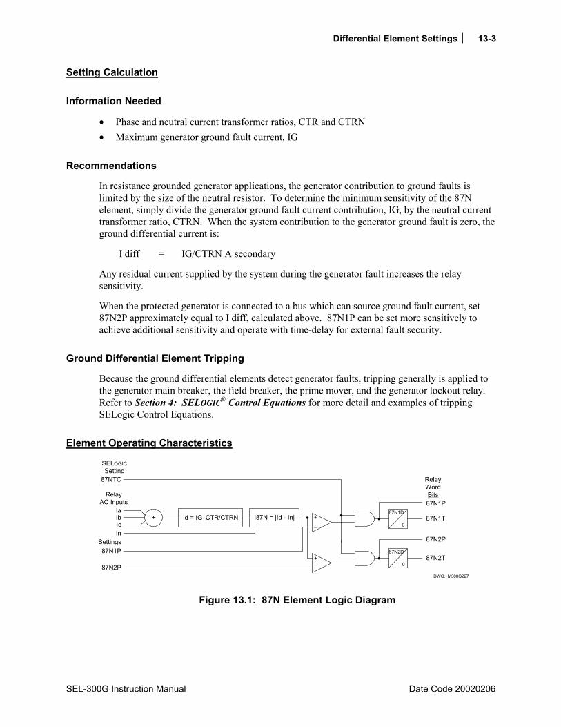
Differential Element Settings 13-3
SEL-300G Instruction Manual Date Code 20020206
Setting Calculation
Information Needed
• Phase and neutral current transformer ratios, CTR and CTRN • Maximum generator ground fault current, IG
Recommendations
In resistance grounded generator applications, the generator contribution to ground faults is limited by the size of the neutral resistor. To determine the minimum sensitivity of the 87N element, simply divide the generator ground fault current contribution, IG, by the neutral current transformer ratio, CTRN. When the system contribution to the generator ground fault is zero, the ground differential current is:
I diff = IG/CTRN A secondary
Any residual current supplied by the system during the generator fault increases the relay sensitivity.
When the protected generator is connected to a bus which can source ground fault current, set 87N2P approximately equal to I diff, calculated above. 87N1P can be set more sensitively to achieve additional sensitivity and operate with time-delay for external fault security.
Ground Differential Element Tripping
Because the ground differential elements detect generator faults, tripping generally is applied to the generator main breaker, the field breaker, the prime mover, and the generator lockout relay. Refer to Section 4: SELOGIC® Control Equations for more detail and examples of tripping SELogic Control Equations.
Element Operating Characteristics
87NTC
Ia
Settings87N1P
SELOGICSetting
RelayAC Inputs
87N2P
+_
87N1D
0
87N2D
087N2T
87N2P
87N1T
87N1P
+ Id = IGCTR/CTRN I87N = |Id - In|
RelayWordBits
DWG: M300G227
+_
IbIcIn
Figure 13.1: 87N Element Logic Diagram

13-4 Differential Element Settings
Date Code 20020206 SEL-300G Instruction Manual
PERCENTAGE RESTRAINED DIFFERENTIAL ELEMENT OVERVIEW (MODELS 0300G1 AND 300G3)
To simplify the setting process for the majority of applications, the SEL-300G1/300G3 Relay differential element is enabled by setting E87 equal to either G or T.
When E87 = G, several of the differential element settings are fixed to default values, leaving only three settings to consider. Set E87 = G when the protected generator is the only apparatus in the differential zone, as shown in Figure 5.13.
When E87 = T, additional settings are available to compensate for the inclusion of a generator step-up transformer in the differential zone, as shown in Figure 5.15.
Setting E87 = N disables differential protection and hides the remaining settings associated with the element.
When E87 = G or T, the differential protection function includes a sensitive, percentage restrained differential element and an unrestrained element that must be set less sensitively.
When E87 = G or T, the relay measures the fundamental frequency currents from the phase inputs (IA1, IB1, and IC1) and the differential inputs (IA871, IB871, and IC871). See Figure 13.2. The relay also measures the second-harmonic current quantities for each set of inputs. The relay mathematically compensates the measured currents, taking into account the current transformer connections, the power transformer connections (if E87 = T), and the TAP settings. Using the compensated currents, the relay next calculates the operate quantities (IOP1, IOP2, and IOP3), the restraint quantities (IRT1, IRT2, and IRT3), and the second-harmonic blocking quantities (I1F2, I2F2, and I3F2).
FundamentalFrequency Digital
Cosine Filter
Second-HarmonicDigital Cosine
Filter
IA
IB
IC
IA87
IB87
IC87
IA1
IB1
IC1
IA871
IB871
IC871
IA2
IB2
IC2
IA872
IB872
IC872
DWG: M300G198
Figure 13.2: Fundamental and Second-Harmonic Filters Provide Current Inputs to Differential Elements
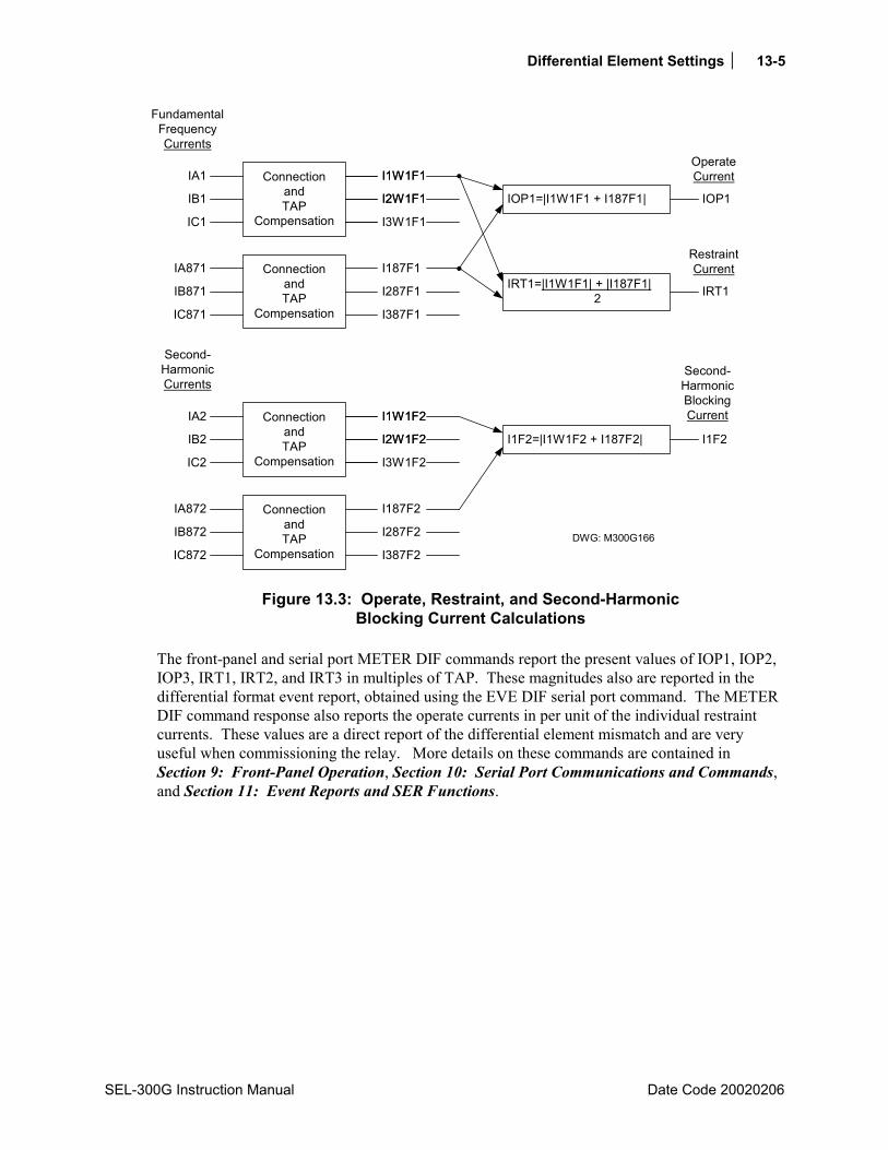
Differential Element Settings 13-5
SEL-300G Instruction Manual Date Code 20020206
ConnectionandTAP
Compensation
ConnectionandTAP
Compensation
FundamentalFrequencyCurrents
IA1
IB1
IC1
IA871
IB871
IC871
Second-HarmonicCurrents
I1W1F1
I2W1F1
I3W1F1
I1W1F1
I2W1F1
I187F1
I287F1
I387F1
ConnectionandTAP
Compensation
ConnectionandTAP
Compensation
IA2
IB2
IC2
IA872
IB872
IC872
I1W1F2
I2W1F2
I3W1F2
I1W1F2
I2W1F2
I187F2
I287F2
I387F2
IOP1=|I1W1F1 + I187F1| IOP1
OperateCurrent
IRT1=|I1W1F1| + |I187F1| 2 IRT1
I1F2=|I1W1F2 + I187F2| I1F2
Second-HarmonicBlockingCurrent
RestraintCurrent
DWG: M300G166
Figure 13.3: Operate, Restraint, and Second-Harmonic Blocking Current Calculations
The front-panel and serial port METER DIF commands report the present values of IOP1, IOP2, IOP3, IRT1, IRT2, and IRT3 in multiples of TAP. These magnitudes also are reported in the differential format event report, obtained using the EVE DIF serial port command. The METER DIF command response also reports the operate currents in per unit of the individual restraint currents. These values are a direct report of the differential element mismatch and are very useful when commissioning the relay. More details on these commands are contained in Section 9: Front-Panel Operation, Section 10: Serial Port Communications and Commands, and Section 11: Event Reports and SER Functions.
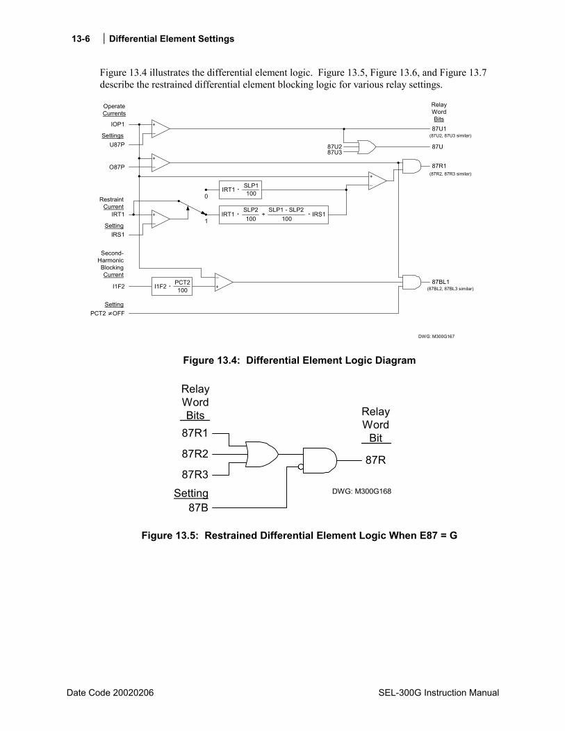
13-6 Differential Element Settings
Date Code 20020206 SEL-300G Instruction Manual
Figure 13.4 illustrates the differential element logic. Figure 13.5, Figure 13.6, and Figure 13.7 describe the restrained differential element blocking logic for various relay settings.
OperateCurrents
87U1
RelayWordBits
DWG: M300G167
_+
_+
IOP1
U87PSettings
O87P
87U
87R1
_+
IRT1 +SLP2100
IRS1SLP1 - SLP2
100
87U287U3
_+IRT1
RestraintCurrent
PCT2 OFFSetting
0
1
Second-HarmonicBlockingCurrent
I1F2 +
_87BL1
(87BL2, 87BL3 similar)
(87R2, 87R3 similar)
(87U2, 87U3 similar)
IRS1Setting
I1F2 PCT2100
IRT1 SLP1100
Figure 13.4: Differential Element Logic Diagram
87R1
87R2
87B
87R
RelayWord
Bit
DWG: M300G168
87R3
RelayWordBits
Setting
Figure 13.5: Restrained Differential Element Logic When E87 = G
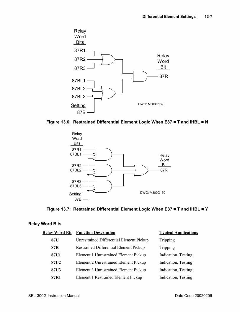
Differential Element Settings 13-7
SEL-300G Instruction Manual Date Code 20020206
87R1
87R2
87R
DWG: M300G169
87R3
RelayWord
Bit
RelayWordBits
87BL187BL2
87BSetting
87BL3
Figure 13.6: Restrained Differential Element Logic When E87 = T and IHBL = N
87R187BL1
87R
DWG: M300G170Setting87B
87R287BL2
87R387BL3
RelayWordBits
RelayWord
Bit
Figure 13.7: Restrained Differential Element Logic When E87 = T and IHBL = Y
Relay Word Bits
Relay Word Bit Function Description Typical Applications
87U Unrestrained Differential Element Pickup Tripping
87R Restrained Differential Element Pickup Tripping
87U1 Element 1 Unrestrained Element Pickup Indication, Testing
87U2 Element 2 Unrestrained Element Pickup Indication, Testing
87U3 Element 3 Unrestrained Element Pickup Indication, Testing
87R1 Element 1 Restrained Element Pickup Indication, Testing
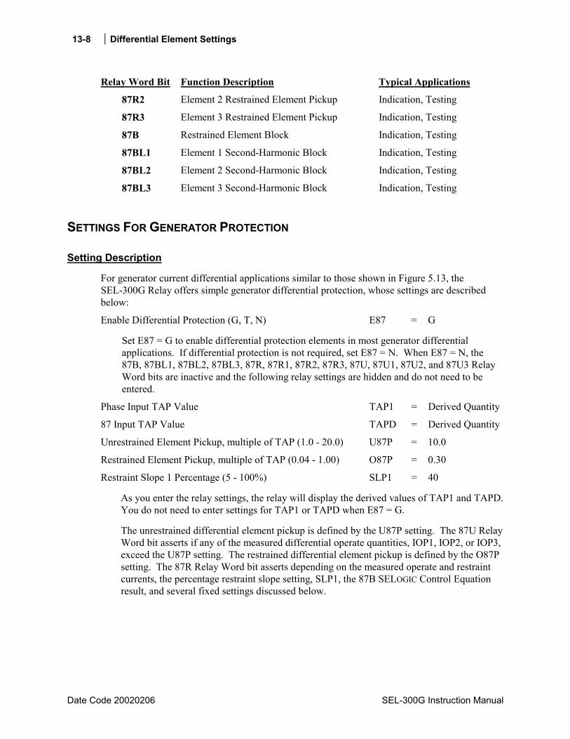
13-8 Differential Element Settings
Date Code 20020206 SEL-300G Instruction Manual
Relay Word Bit Function Description Typical Applications
87R2 Element 2 Restrained Element Pickup Indication, Testing
87R3 Element 3 Restrained Element Pickup Indication, Testing
87B Restrained Element Block Indication, Testing
87BL1 Element 1 Second-Harmonic Block Indication, Testing
87BL2 Element 2 Second-Harmonic Block Indication, Testing
87BL3 Element 3 Second-Harmonic Block Indication, Testing
SETTINGS FOR GENERATOR PROTECTION
Setting Description
For generator current differential applications similar to those shown in Figure 5.13, the SEL-300G Relay offers simple generator differential protection, whose settings are described below:
Enable Differential Protection (G, T, N) E87 = G
Set E87 = G to enable differential protection elements in most generator differential applications. If differential protection is not required, set E87 = N. When E87 = N, the 87B, 87BL1, 87BL2, 87BL3, 87R, 87R1, 87R2, 87R3, 87U, 87U1, 87U2, and 87U3 Relay Word bits are inactive and the following relay settings are hidden and do not need to be entered.
Phase Input TAP Value TAP1 = Derived Quantity
87 Input TAP Value TAPD = Derived Quantity
Unrestrained Element Pickup, multiple of TAP (1.0 - 20.0) U87P = 10.0
Restrained Element Pickup, multiple of TAP (0.04 - 1.00) O87P = 0.30
Restraint Slope 1 Percentage (5 - 100%) SLP1 = 40
As you enter the relay settings, the relay will display the derived values of TAP1 and TAPD. You do not need to enter settings for TAP1 or TAPD when E87 = G.
The unrestrained differential element pickup is defined by the U87P setting. The 87U Relay Word bit asserts if any of the measured differential operate quantities, IOP1, IOP2, or IOP3, exceed the U87P setting. The restrained differential element pickup is defined by the O87P setting. The 87R Relay Word bit asserts depending on the measured operate and restraint currents, the percentage restraint slope setting, SLP1, the 87B SELOGIC Control Equation result, and several fixed settings discussed below.
Differential Element Settings 13-9
SEL-300G Instruction Manual Date Code 20020206
The relay performs internal range checking on the U87P and O87P settings and the derived TAP quantities. The following secondary ranges are required:
(0.1 In) ≤ (U87P TAPmin) (U87P TAPmax) ≤ (32 In) (0.04 In) ≤ (O87P TAPmin) (O87P TAPmax) ≤ (32 In)
where:
In = 1 A or 5 A rating of the relay phase current inputs
TAPmax/TAPmin ≤ 7.5
where:
TAPmax is the larger and TAPmin the smaller of the two TAP values TAP1 and TAPD
If one of the U87P or O87P range checks fails, the relay will prompt you to reenter the differential pickup setting. When E87 = G, if the ratio of TAPmax to TAPmin is greater than 7.5, it typically indicates an error in the CTR or CTRD setting entry. The relay will indicate an error and prompt you for corrected CTR and CTRD settings. If the CTR and CTRD settings are correct and the TAPmax/TAPmin range check still fails, consider using E87 = T.
Restrained Element Block (SELOGIC Control Equation) 87B = 0
The percentage restrained differential element is disabled when the 87B SELOGIC Control Equation result is a logical 1. Most applications permit the 87 elements to be enabled all the time, suggesting the 87B should be set to logical 0.
When E87 = G, the relay hides the following settings, and uses their default values in the element definition:
XFMR Connection TRCON = GEN
87 Input CT Connection (Y, DAB, DAC) CTCON = Y
Restraint Slope 2 Percentage (OFF, 50 - 200%) SLP2 = 100
Restraint Slope 1 Limit, multiple of TAP (1.0 - 16.0) IRS1 = 3.0
Second-Harmonic Blocking Percent (OFF, 5-100%) PCT2 = OFF
Setting Calculation
Unrestrained Differential Element Pickup Setting, U87P
The instantaneous, unrestrained differential element is intended to detect very high difference currents that clearly indicate an internal fault. This element responds only to the fundamental frequency component of the differential operate current and is not affected by the percentage restraint function. It should be set high enough to not respond to false difference current caused by differences in CT performance for heavy through-faults. Setting U87P = 10 generally provides satisfactory performance.
13-10 Differential Element Settings
Date Code 20020206 SEL-300G Instruction Manual
Note that the relay requires the following inequality be true:
(U87P TAPmax) (32 In)
where:
In = 1 A or 5 A rating of the relay phase current inputs TAPmax is the larger of the two quantities, INOM or INOM* (CTR/CTRD)
Restrained Differential Element Pickup Setting, O87P
Set the restrained element operate current pickup at a minimum value for increased sensitivity but high enough to avoid incorrect operation due to steady state CT error. An O87P setting of 0.3 generally provides satisfactory performance.
Note that the relay requires the following inequality be true:
(087P TAPmin) (0.04 In)
where:
In = 1 A or 5 A rating of the relay phase current inputs TAPmin is the smaller of the two quantities, INOM or INOM (CTR/CTRD)
Restrained Differential Element Slope 1 Setting, SLP1 The sensitive differential element percentage restraint characteristic improves the element security during heavy through-faults. During the external fault, the CT ratio errors may increase, causing the relay to measure differential current. To prevent incorrect operation during this condition, the relay automatically increases the required operate current in direct proportion to the measured restraint current, by a settable amount, SLP1.
If the CT error for each of the two CTs is ±10% and the relay differential measurement error is ≤5%, then the minimum SLP1 setting is 25%.
Fixed Settings: SLP2, IRS1, PCT2 When E87 = G, the relay fixes the values of SLP2 = 100%, IRS1 = 3 per unit of TAP, and PCT2 = OFF. These settings disable second-harmonic blocking, which is not required in the vast majority of generator differential applications and set conservative values for the percentage restraint characteristic during external faults whose current is higher than three times TAP.
Derived Settings: TAP1, TAPD When E87 = G, the relay derives the values of TAP1 and TAPD. TAP1 automatically is set equal to the generator nominal current in secondary amps, defined by the INOM setting. TAPD is set equal to the same current, placed in terms of secondary A at the differential input CTs: TAPD = INOM CTR/CTRD.
Differential Element Settings 13-11
SEL-300G Instruction Manual Date Code 20020206
The relay requires that the ratio of the maximum TAP to the minimum TAP be less than 7.5:1. In the vast majority of applications, CTR CTRD, so this requirement should not cause a problem.The relay uses the TAP1 and TAPD values in the Connection and TAP Compensation function shown in Figure 13.3. When E87 = G, only TAP compensation is performed. I1W1F1 equals IA1 divided by TAP1. I187F1 equals IA87 divided by TAPD.
Differential Element Tripping The 87U and 87R differential elements detect faults and usually are used to trip the main generator breaker, the field breaker, the prime mover, and the generator lockout relay. Refer to Section 4: SELOGIC® Control Equations for more detail and examples of tripping SELOGIC Control Equations.
SETTINGS FOR UNIT PROTECTION
Setting Description
For unit current differential applications similar to those shown in Figure 5.15, the SEL-300G Relay offers differential protection that can compensate correctly for the ratio and phase shift of the generator step-up transformer.
Enable Differential Protection (G, T, N) E87 = T
Set E87 = T to enable differential protection elements when the generator step-up transformer is included in the differential zone. If differential protection is not required, set E87 = N. When E87 = N, the 87B, 87BL1, 87BL2, 87BL3, 87R, 87R1, 87R2, 87R3, 87U, 87U1, 87U2, and 87U3 Relay Word bits are inactive and the following relay settings are hidden and do not need to be entered.
XFMR High-Side Winding L-L Voltage (OFF, 1.0 1000.0 kV) VWDGD = 13.8
XFMR Connection (GEN, YY, YDAC, YDAB, DACDAC, DABDAB, DABY, DACY) TRCON = DABY
87 Input CT Connection (Y, DAB, DAC) CTCON = DAB
Phase Input TAP Value TAP1 = Derived Quantity
87 Input TAP Value TAPD = Derived Quantity
Unrestrained Element Pickup, multiple of TAP (1.0 20.0) U87P = 10.0
Restrained Element Pickup, multiple of TAP (0.04 1.00) O87P = 0.30
Restraint Slope 1 Percentage (5 100%) SLP1 = 40
When a generator step-up transformer is included in the differential zone, set VWDGD equal to the transformer rated high-side voltage in line-to-line kilovolts. If you are setting E87 = T, but not including a power transformer in the differential zone, either set VWDGD equal to the generator rate line-to-line voltage or set VWDGD = OFF.
The TRCON setting is defined by the step-up transformer connections. The CTCON setting is defined by the connection of the 87 input current transformers.
13-12 Differential Element Settings
Date Code 20020206 SEL-300G Instruction Manual
As you enter the relay settings, the relay will display the derived values of TAP1 and TAPD. If you enter a setting for VWDGD, you do not need to enter settings for TAP1 or TAPD when E87 = T. When you set VWDGD = OFF, you will need to calculate and enter settings for TAP1 and TAPD using the instructions below.
The unrestrained differential element pickup is defined by the U87P setting. The 87U Relay Word bit asserts if any of the measured differential operate quantities, IOP1, IOP2, or IOP3, exceeds the U87P setting. The restrained differential element pickup is defined by the O87P setting. The 87R Relay Word bit asserts depending on the measured operate and restraint currents, the percentage restraint slope settings, SLP1, SLP2, and IRS1, the second-harmonic blocking function defined by PCT2 and IHBL settings, and the 87B SELOGIC Control Equation result.
The relay performs internal range checking on the U87P and O87P settings and the derived TAP quantities. The following secondary ranges are required:
0.1 In A secondary ≤ U87P TAPmin U87P TAPmax ≤ 32 In A secondary 0.04 In A secondary ≤ O87P TAPmin O87P TAPmax ≤ 32 In A secondary
where:
In = 1 A or 5 A rating of the relay phase current inputs TAPmax/TAPmin ≤ 7.5
If one of the U87P or O87P range checks fails, the relay will prompt you to reenter the differential pickup setting. If the ratio of TAPmax to TAPmin is greater than 7.5, it typically indicates an error in the CTR, CTRD, or VWDGD setting entry. The relay will indicate an error and prompt you for corrected settings. If the settings are correct and the TAPmax/TAPmin range check still fails, consider setting VWDGD = OFF, directly setting the TAP quantities within range, and desensitizing the O87P setting.
Restraint Slope 2 Percentage (OFF, 50 200%) SLP2 = 100
Restraint Slope 1 Limit, multiple of TAP (1.0 16.0) IRS1 = 3.0
Second Harmonic Blocking Percent (OFF, 5 100%) PCT2 = 12
Independent Harmonic Blocking (Y, N) IHBL = N
The SLP2 and IRS1 settings define the second percentage restraint slope. As shown in Figure 13.8, the SLP2 slope is effective when the measured restraint current is greater than IRS1 times TAP. If a second slope is not desired, set SLP2 = OFF. When SLP2 = OFF, the relay hides the IRS1 setting and does not require that you enter a value.
The PCT2 setting defines a second-harmonic blocking percentage. In the majority of unit protection applications, setting PCT2 to OFF or 12% will provide satisfactory performance.
When PCT2 = OFF, the IHBL setting is hidden and does not require a value.

Differential Element Settings 13-13
SEL-300G Instruction Manual Date Code 20020206
Restrained Element Block (SELOGIC Control Equation) 87B = 0
The percentage restrained differential element is disabled when the 87B SELOGIC Control Equation result is a logical 1. When the differential element is applied for unit protection, you may wish to set 87B = 24C2. This blocks the differential element during overexcitation conditions when fifth-harmonic current might cause the differential element to incorrectly pick up.
Setting Calculation
Transformer High-Side Line-to-Line Voltage, VWDGD The VWDGD setting is used to derive the TAPD value. When a generator step-up transformer is included in the differential zone, set VWDGD equal to the transformer rated high-side voltage in line-to-line kilovolts. If you are setting E87 = T, but not including a power transformer in the differential zone, either set VWDGD equal to the generator rate line-to-line voltage or set VWDGD = OFF. When VWDGD = OFF, the TAP1 and TAPD settings must be calculated and entered manually, as discussed below.
Transformer and CT Connection Settings, TRCON and CTCON The TRCON setting is defined by the generator step-up transformer connections. The setting represents both windings. For instance, TRCON = DABY indicates that the transformer winding connected to the generator is delta connected and the high side is wye connected. Appendix B: Differential Connection Diagrams shows the transformer connections associated with each of the available TRCON settings.
The CTCON setting is defined by the 87 input current transformer connection. CTCON = Y indicates the current transformers are wye connected. CTCON = DAB indicates that the current transformers are delta connected, with the polarity of the A-phase CT connected to the nonpolarity side of the B-phase CT. CTCON = DAC indicates that the current transformers are delta connected, with the polarity of the A-phase CT connected to the nonpolarity side of the C-phase CT. See Appendix B: Differential Connection Diagrams for example connection diagrams.
Derived Tap Settings, TAP1, TAPD When E87 = T and VWDGD is not OFF, the relay derives the values of TAP1 and TAPD. TAP1 automatically is set equal to the generator nominal current in secondary amps, defined by the INOM setting. TAPD is set equal to the same current, placed in terms of secondary amps at the differential input CTs, taking into account the power transformer ratio and connections and the current transformer ratios and connections:
CTRDVWDGD1000C2CTRPTRINOMVNOMTAPD = A
where:
VNOM, INOM, PTR, CTR, VWDGD, CTRD = relay settings
C2 = 1.732 if CTCON = DAB or DAC
C2 = 1.0 for all other combinations of TRCON and CTCON

13-14 Differential Element Settings
Date Code 20020206 SEL-300G Instruction Manual
The relay requires that the ratio of the maximum TAP to the minimum TAP be less than 7.5:1 which is feasible for the vast majority of applications. If your particular application calls for a higher ratio of TAPmax to TAPmin, take one of the following remedial actions to lower the TAP ratio:
1. Select a different current transformer ratio for either the phase or 87 input current transformers.
2. Use an auxiliary current transformer in secondary circuits of the 87 input current transformers to modify the current transformer ratio apparent to the SEL-300G Relay.
3. Set VWDGD = OFF then manually set TAP1 and TAPD to values that are close but not equal to the ideal derived values. These nonideal TAP values must still meet the 7.5:1 ratio criteria. Because they are not ideal, they will result in nonzero mismatch in the relay differential element. This will require that you select higher values for O87P, SLP1, and SLP2 to maintain security during through-faults.
Unrestrained Differential Element Pickup Setting, U87P
The instantaneous, unrestrained differential element is intended to detect very high difference currents that clearly indicate an internal fault. This element responds only to the fundamental frequency component of the differential operate current and is not affected by the percentage restraint function. It should be set high enough to not respond to false difference current caused by differences in CT performance for heavy through-faults. Setting U87P = 10 generally provides satisfactory performance.
Note that the relay requires the following inequality be true:
U87P TAPmax 32 In
where:
In = 1 A or 5 A rating of the relay phase current inputs TAPmax is the larger of the two TAP quantities
Restrained Differential Element Pickup Setting, O87P
Set the restrained element operate current pickup at a minimum value for increased sensitivity, but high enough to avoid incorrect operation due to steady state CT error. An O87P setting of 0.3 generally provides satisfactory performance.
Note that the relay requires the following inequality be true:
O87P TAPmin 0.04 In
where:
In = 1 A or 5 A rating of the relay phase current inputs TAPmin is the smaller of the two TAP quantitiesRestrained Differential Element Slope 1 Setting, SLP1
The sensitive differential element percentage restraint characteristic improves the element security during heavy through-faults. During the external fault, the CT ratio errors may increase,
Differential Element Settings 13-15
SEL-300G Instruction Manual Date Code 20020206
causing the relay to measure differential current. To prevent incorrect operation during this condition, the relay automatically increases the required operate current in direct proportion to the measured restraint current by a settable amount, SLP1.
If the CT error for each of the two CTs is ±10%, and the relay differential measurement error is ≤5%, then the minimum SLP1 setting is 25%.
Percentage Restraint Slope 2 Settings, SLP2, IRS1
When E87 = T, you may enter settings for SLP2 and IRS1. Setting IRS1 = 3 per unit of TAP and SLP2 = 60% to 100% provide restrained element security for deteriorating CT performance during high-current external faults. Higher values of SLP2 provide security for some degree of CT saturation. If you set SLP2 = OFF, the IRS1 setting is hidden and the SLP1 setting is applied to the entire range of differential element operation and should be higher than discussed above to provide security during high-current through-faults.
Second-Harmonic Blocking Settings, PCT2, IHBL
The PCT2 setting defines the restrained element second-harmonic blocking level. Setting PCT2 = OFF disables second-harmonic blocking and the relay hides the IHBL setting.
When PCT2 is not set to OFF, if the differential current contains more than PCT2 percent of second harmonic due to magnetizing inrush or CT saturation, the restrained differential element is blocked. The unrestrained element is not affected. In transformer differential applications, the traditional PCT2 setting is 12% to 15% to provide security during transformer magnetizing inrush conditions. In the majority of unit protection applications, setting PCT2 to OFF or 12% will provide satisfactory performance.
When PCT2 is not set to OFF, the IHBL setting offers two ways to perform harmonic blocking:
1. Common Harmonic Blocking (IHBL = N) blocks all of the percentage differential elements if any one phase has a second-harmonic magnitude above the PCT2 threshold (see Figure 13.6).
2. Independent Harmonic Blocking (IHBL = Y) blocks the percentage differential element for a particular phase if the second harmonic in that phase is above the PCT2 threshold. The other two differential elements are blocked by their own second-harmonic measurement only (see Figure 13.7).
Set IHBL = N in the majority of applications to improve the restrained element security.
Differential Element Tripping
The 87U and 87R differential elements detect faults and usually are used to trip the main generator breaker, the field breaker, the prime, and the generator lockout relay. Refer to Section 4: SELOGIC® Control Equations for more detail and examples of tripping SELOGIC Control Equations.
13-16 Differential Element Settings
Date Code 20020206 SEL-300G Instruction Manual
DIFFERENTIAL ELEMENT TRANSFORMER CONNECTION AND RATIO COMPENSATION
Figure 13.3 shows that the relay performs compensation on the measured phase currents before performing any other differential element calculations. TAP compensation accounts for CT and power transformer ratios, and, partially, for the CT and transformer connections. Additional phase-shift compensation is needed for certain combinations of CT and transformer connection. Table 13.1 and the following discussion fully define the Connection and TAP Compensation referred to in Figure 13.3.
Table 13.1: Connection and TAP Compensation
TRCON CTCON CON1 CON2
GEN Y Y Y
DACDAC Y Y Y
DABDAB Y Y Y
DABY DAB Y Y
DACY DAC Y Y
YY Y DAB DAB
YDAC Y DAC Y
YDAB Y DAB Y
DABY Y Y DAB
DACY Y Y DAC
For CON1 = Y: I1W1F1 = IA1/TAP1 I2W1F1 = IB1/TAP1 I3W1F1 = IC1/TAP1
For CON2 = Y: I187F1 = IA871/TAPD I287F1 = IB871/TAPD I387F1 = IC871/TAPD
For CON1 = DAB:
TAP13IB1IA1I1W1F1 −=
TAP13IC1IB1I2W1F1 −=
TAP13IA1IC1I3W1F1 −=
For CON2 = DAB:
TAPD3IB871IA871I187F1 −=
TAPD3IC871IB871I287F1 −=
TAPD3IA871IC871I387F1 −=
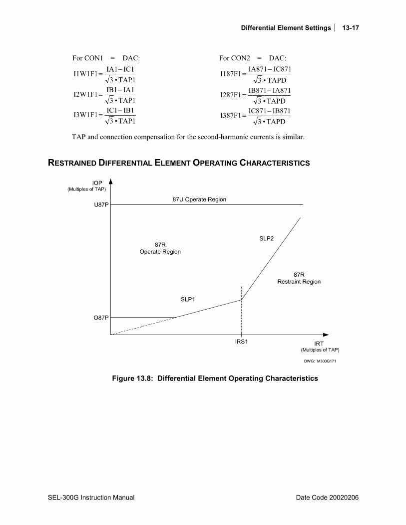
Differential Element Settings 13-17
SEL-300G Instruction Manual Date Code 20020206
For CON1 = DAC:
TAP13IC1IA1I1W1F1 −=
TAP13IA1IB1I2W1F1 −=
TAP13IB1IC1I3W1F1 −=
For CON2 = DAC:
TAPD3IC871IA871I187F1 −=
TAPD3IA871IB871I287F1 −=
TAPD3IB871IC871I387F1 −=
TAP and connection compensation for the second-harmonic currents is similar.
RESTRAINED DIFFERENTIAL ELEMENT OPERATING CHARACTERISTICS
IRS1 IRT(Multiples of TAP)
O87P
U87P
(Multiples of TAP)IOP
SLP1
SLP287R
Operate Region
87U Operate Region
87RRestraint Region
DWG: M300G171
Figure 13.8: Differential Element Operating Characteristics


SEL-300G Instruction Manual Date Code 20020206
TABLE OF CONTENTS
APPENDIX A: FIRMWARE VERSIONS............................................... A-1
Determining the Firmware Version in Your Relay......................................................................A-1
APPENDIX B: DIFFERENTIAL CONNECTION DIAGRAMS ...............B-1
APPENDIX C: SEL DISTRIBUTED PORT SWITCH PROTOCOL.......C-1
Settings.........................................................................................................................................C-1 Operation......................................................................................................................................C-1
APPENDIX D: CONFIGURATION, FAST METER, AND FAST OPERATE COMMANDS ..............................................D-1
Introduction ..................................................................................................................................D-1 Message Lists ...............................................................................................................................D-1
Binary Message List.............................................................................................................D-1 ASCII Configuration Message List ......................................................................................D-1
Message Definitions.....................................................................................................................D-2 A5C0 Relay Definition Block ..............................................................................................D-2 A5C1 Fast Meter Configuration Block................................................................................D-2 A5D1 Fast Meter Data Block ............................................................................................D-11 A5C2/A5C3 Demand/Peak Demand Fast Meter Configuration Messages .......................D-12 A5D2/A5D3 Demand/Peak Demand Fast Meter Message................................................D-14 A5B9 Fast Meter Status Acknowledge Message...............................................................D-15 A5CE Fast Operate Configuration Block..........................................................................D-15 A5E0 Fast Operate Remote Bit Control............................................................................D-16 A5E3 Fast Operate Breaker Control .................................................................................D-17 ID Message.........................................................................................................................D-17 DNA Message ....................................................................................................................D-18 BNA Message.....................................................................................................................D-28
APPENDIX E: COMPRESSED ASCII COMMANDS............................ E-1
Introduction .................................................................................................................................. E-1 CASCII Command General Format .......................................................................................... E-1 CASCII Command SEL-300G .................................................................................................. E-2 CSTATUS Command SEL-300G ............................................................................................. E-7 CHISTORY Command SEL-300G ........................................................................................... E-9 CEVENT Command SEL-300G ............................................................................................... E-9
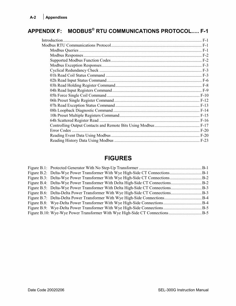
A-2 Appendixes
Date Code 20020206 SEL-300G Instruction Manual
APPENDIX F: MODBUS® RTU COMMUNICATIONS PROTOCOL..... F-1
Introduction .................................................................................................................................. F-1 Modbus RTU Communications Protocol..................................................................................... F-1
Modbus Queries ................................................................................................................... F-1 Modbus Responses............................................................................................................... F-2 Supported Modbus Function Codes ..................................................................................... F-2 Modbus Exception Responses.............................................................................................. F-3 Cyclical Redundancy Check ................................................................................................ F-3 01h Read Coil Status Command .......................................................................................... F-3 02h Read Input Status Command......................................................................................... F-6 03h Read Holding Register Command................................................................................. F-8 04h Read Input Registers Command.................................................................................... F-9 05h Force Single Coil Command ....................................................................................... F-10 06h Preset Single Register Command ................................................................................ F-12 07h Read Exception Status Command ............................................................................... F-13 08h Loopback Diagnostic Command ................................................................................. F-14 10h Preset Multiple Registers Command........................................................................... F-15 64h Scattered Register Read .............................................................................................. F-16 Controlling Output Contacts and Remote Bits Using Modbus .......................................... F-17 Error Codes ........................................................................................................................ F-20 Reading Event Data Using Modbus ................................................................................... F-20 Reading History Data Using Modbus ................................................................................ F-23
FIGURES Figure B.1: Protected Generator With No Step-Up Transformer ...........................................................B-1 Figure B.2: Delta-Wye Power Transformer With Wye High-Side CT Connections..............................B-1 Figure B.3: Delta-Wye Power Transformer With Wye High-Side CT Connections..............................B-2 Figure B.4: Delta-Wye Power Transformer With Delta High-Side CT Connections.............................B-2 Figure B.5: Delta-Wye Power Transformer With Delta High-Side CT Connections.............................B-3 Figure B.6: Delta-Delta Power Transformer With Wye High-Side CT Connections.............................B-3 Figure B.7: Delta-Delta Power Transformer With Wye High-Side Connections...................................B-4 Figure B.8: Wye-Delta Power Transformer With Wye High-Side Connections....................................B-4 Figure B.9: Wye-Delta Power Transformer With Wye High-Side Connections....................................B-5 Figure B.10: Wye-Wye Power Transformer With Wye High-Side CT Connections...............................B-5
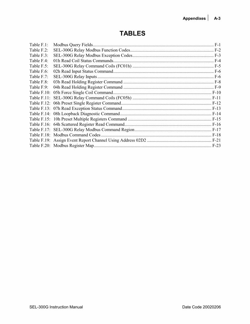
Appendixes A-3
SEL-300G Instruction Manual Date Code 20020206
TABLES Table F.1: Modbus Query Fields........................................................................................................... F-1 Table F.2: SEL-300G Relay Modbus Function Codes.......................................................................... F-2 Table F.3: SEL-300G Relay Modbus Exception Codes........................................................................ F-3 Table F.4: 01h Read Coil Status Commands......................................................................................... F-4 Table F.5: SEL-300G Relay Command Coils (FC01h) ........................................................................ F-5 Table F.6: 02h Read Input Status Command......................................................................................... F-6 Table F.7: SEL-300G Relay Inputs ....................................................................................................... F-6 Table F.8: 03h Read Holding Register Command ................................................................................ F-8 Table F.9: 04h Read Holding Register Command ................................................................................ F-9 Table F.10: 05h Force Single Coil Command....................................................................................... F-10 Table F.11: SEL-300G Relay Command Coils (FC05h) ...................................................................... F-11 Table F.12: 06h Preset Single Register Command................................................................................ F-12 Table F.13: 07h Read Exception Status Command............................................................................... F-13 Table F.14: 08h Loopback Diagnostic Command................................................................................. F-14 Table F.15: 10h Preset Multiple Registers Command .......................................................................... F-15 Table F.16: 64h Scattered Register Read Command............................................................................. F-16 Table F.17: SEL-300G Relay Modbus Command Region.................................................................... F-17 Table F.18: Modbus Command Codes.................................................................................................. F-18 Table F.19: Assign Event Report Channel Using Address 02D2 ......................................................... F-21 Table F.20: Modbus Register Map........................................................................................................ F-23

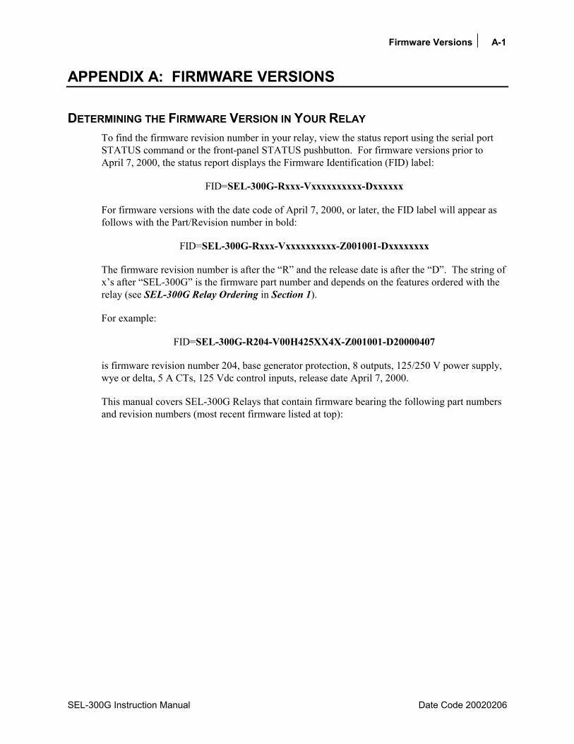
Firmware Versions A-1
SEL-300G Instruction Manual Date Code 20020206
APPENDIX A: FIRMWARE VERSIONS
DETERMINING THE FIRMWARE VERSION IN YOUR RELAY To find the firmware revision number in your relay, view the status report using the serial port STATUS command or the front-panel STATUS pushbutton. For firmware versions prior to April 7, 2000, the status report displays the Firmware Identification (FID) label:
FID=SEL-300G-Rxxx-Vxxxxxxxxxx-Dxxxxxx
For firmware versions with the date code of April 7, 2000, or later, the FID label will appear as follows with the Part/Revision number in bold:
FID=SEL-300G-Rxxx-Vxxxxxxxxxx-Z001001-Dxxxxxxxx
The firmware revision number is after the R and the release date is after the D. The string of xs after SEL-300G is the firmware part number and depends on the features ordered with the relay (see SEL-300G Relay Ordering in Section 1).
For example:
FID=SEL-300G-R204-V00H425XX4X-Z001001-D20000407
is firmware revision number 204, base generator protection, 8 outputs, 125/250 V power supply, wye or delta, 5 A CTs, 125 Vdc control inputs, release date April 7, 2000.
This manual covers SEL-300G Relays that contain firmware bearing the following part numbers and revision numbers (most recent firmware listed at top):
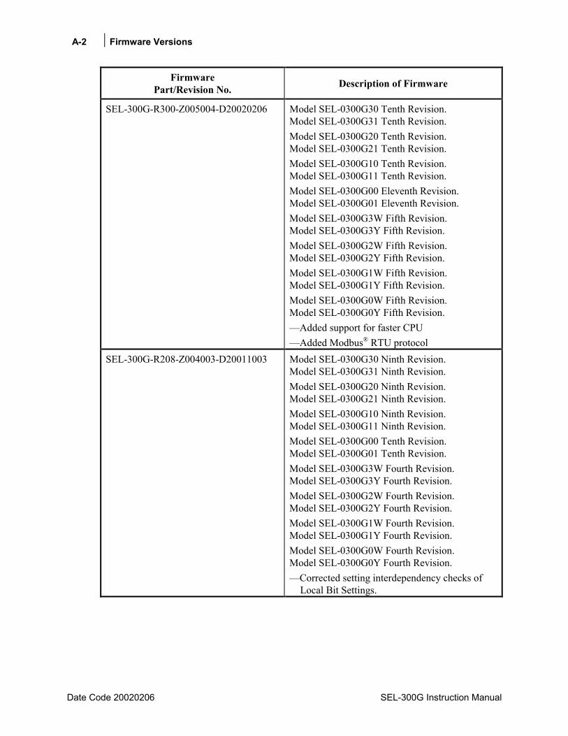
A-2 Firmware Versions
Date Code 20020206 SEL-300G Instruction Manual
Firmware Part/Revision No. Description of Firmware
SEL-300G-R300-Z005004-D20020206 Model SEL-0300G30 Tenth Revision. Model SEL-0300G31 Tenth Revision. Model SEL-0300G20 Tenth Revision. Model SEL-0300G21 Tenth Revision. Model SEL-0300G10 Tenth Revision. Model SEL-0300G11 Tenth Revision. Model SEL-0300G00 Eleventh Revision. Model SEL-0300G01 Eleventh Revision. Model SEL-0300G3W Fifth Revision. Model SEL-0300G3Y Fifth Revision. Model SEL-0300G2W Fifth Revision. Model SEL-0300G2Y Fifth Revision. Model SEL-0300G1W Fifth Revision. Model SEL-0300G1Y Fifth Revision. Model SEL-0300G0W Fifth Revision. Model SEL-0300G0Y Fifth Revision. Added support for faster CPU Added Modbus® RTU protocol
SEL-300G-R208-Z004003-D20011003 Model SEL-0300G30 Ninth Revision. Model SEL-0300G31 Ninth Revision. Model SEL-0300G20 Ninth Revision. Model SEL-0300G21 Ninth Revision. Model SEL-0300G10 Ninth Revision. Model SEL-0300G11 Ninth Revision. Model SEL-0300G00 Tenth Revision. Model SEL-0300G01 Tenth Revision. Model SEL-0300G3W Fourth Revision. Model SEL-0300G3Y Fourth Revision. Model SEL-0300G2W Fourth Revision. Model SEL-0300G2Y Fourth Revision. Model SEL-0300G1W Fourth Revision. Model SEL-0300G1Y Fourth Revision. Model SEL-0300G0W Fourth Revision. Model SEL-0300G0Y Fourth Revision. Corrected setting interdependency checks of
Local Bit Settings.

Firmware Versions A-3
SEL-300G Instruction Manual Date Code 20020206
Firmware Part/Revision No. Description of Firmware
SEL-300G-R207-Z004003-D20010615 Model SEL-0300G30 Eighth Revision. Model SEL-0300G31 Eighth Revision. Model SEL-0300G20 Eighth Revision. Model SEL-0300G21 Eighth Revision. Model SEL-0300G10 Eighth Revision. Model SEL-0300G11 Eighth Revision. Model SEL-0300G00 Ninth Revision. Model SEL-0300G01 Ninth Revision. Model SEL-0300G3W Third Revision. Model SEL-0300G3Y Third Revision. Model SEL-0300G2W Third Revision. Model SEL-0300G2Y Third Revision. Model SEL-0300G1W Third Revision. Model SEL-0300G1Y Third Revision. Model SEL-0300G0W Third Revision. Model SEL-0300G0Y Third Revision. Increased CTR and CTRD setting range to
1-30000 for 1 A version relays. Corrected 87N element to prevent potential
unreliable operations. Corrected ability to set RTD, 32, and 25
elements from front panel.

A-4 Firmware Versions
Date Code 20020206 SEL-300G Instruction Manual
Firmware Part/Revision No. Description of Firmware
SEL-300G-R206-Z003003-D20001212 Model SEL-0300G30 Seventh Revision. Model SEL-0300G31 Seventh Revision. Model SEL-0300G20 Seventh Revision. Model SEL-0300G21 Seventh Revision. Model SEL-0300G10 Seventh Revision. Model SEL-0300G11 Seventh Revision. Model SEL-0300G00 Eighth Revision. Model SEL-0300G01 Eighth Revision. Model SEL-0300G3W Second Revision. Model SEL-0300G3Y Second Revision. Model SEL-0300G2W Second Revision. Model SEL-0300G2Y Second Revision. Model SEL-0300G1W Second Revision. Model SEL-0300G1Y Second Revision. Model SEL-0300G0W Second Revision. Model SEL-0300G0Y Second Revision. Added compatibility with SEL-2600 Added thermal elements Add thermal metering Allow TRGTR to be in SER Improve frequency metering display Improve current meter display accuracy at low
levels Increase 25RCF setting to range 0.5-2.000
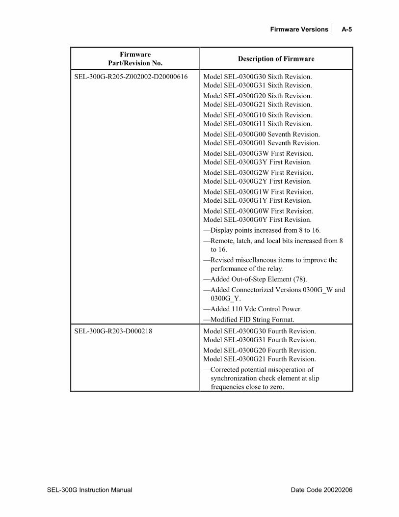
Firmware Versions A-5
SEL-300G Instruction Manual Date Code 20020206
Firmware Part/Revision No. Description of Firmware
SEL-300G-R205-Z002002-D20000616 Model SEL-0300G30 Sixth Revision. Model SEL-0300G31 Sixth Revision. Model SEL-0300G20 Sixth Revision. Model SEL-0300G21 Sixth Revision. Model SEL-0300G10 Sixth Revision. Model SEL-0300G11 Sixth Revision. Model SEL-0300G00 Seventh Revision. Model SEL-0300G01 Seventh Revision. Model SEL-0300G3W First Revision. Model SEL-0300G3Y First Revision. Model SEL-0300G2W First Revision. Model SEL-0300G2Y First Revision. Model SEL-0300G1W First Revision. Model SEL-0300G1Y First Revision. Model SEL-0300G0W First Revision. Model SEL-0300G0Y First Revision. Display points increased from 8 to 16. Remote, latch, and local bits increased from 8
to 16. Revised miscellaneous items to improve the
performance of the relay. Added Out-of-Step Element (78). Added Connectorized Versions 0300G_W and
0300G_Y. Added 110 Vdc Control Power. Modified FID String Format.
SEL-300G-R203-D000218 Model SEL-0300G30 Fourth Revision. Model SEL-0300G31 Fourth Revision. Model SEL-0300G20 Fourth Revision. Model SEL-0300G21 Fourth Revision. Corrected potential misoperation of
synchronization check element at slip frequencies close to zero.

A-6 Firmware Versions
Date Code 20020206 SEL-300G Instruction Manual
Firmware Part/Revision No. Description of Firmware
SEL-300G-R202-D990510 Model SEL-0300G30 Third Revision. Model SEL-0300G31 Third Revision. Model SEL-0300G20 Third Revision. Model SEL-0300G21 Third Revision. Model SEL-0300G10 Fourth Revision. Model SEL-0300G11 Fourth Revision. Model SEL-0300G00 Fifth Revision. Model SEL-0300G01 Fifth Revision. Software maintenance: no performance
modification. SEL-300G-R201-D981204 Model SEL-0300G30 Second Revision.
Model SEL-0300G31 Second Revision. Model SEL-0300G20 Second Revision. Model SEL-0300G21 Second Revision. Model SEL-0300G10 Third Revision. Model SEL-0300G11 Third Revision. Model SEL-0300G00 Fourth Revision. Model SEL-0300G01 Fourth Revision. Corrected scaling error in directional power
and phase distance elements - 1 A Models only. Corrected positive-sequence impedance
calculation for phase distance load encroachment function.
Corrected front-panel serial port setting baud rate range typographical error.
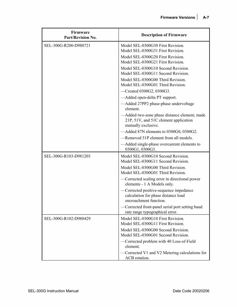
Firmware Versions A-7
SEL-300G Instruction Manual Date Code 20020206
Firmware Part/Revision No. Description of Firmware
SEL-300G-R200-D980721 Model SEL-0300G30 First Revision. Model SEL-0300G31 First Revision. Model SEL-0300G20 First Revision. Model SEL-0300G21 First Revision. Model SEL-0300G10 Second Revision. Model SEL-0300G11 Second Revision. Model SEL-0300G00 Third Revision. Model SEL-0300G01 Third Revision. Created 0300G2, 0300G3. Added open-delta PT support. Added 27PP2 phase-phase undervoltage
element. Added two-zone phase distance element; made
21P, 51V, and 51C element application mutually exclusive.
Added 87N elements to 0300G0, 0300G2. Removed 51P element from all models. Added single-phase overcurrent elements to
0300G1, 0300G3. SEL-300G-R103-D981203 Model SEL-0300G10 Second Revision.
Model SEL-0300G11 Second Revision. Model SEL-0300G00 Third Revision. Model SEL-0300G01 Third Revision. Corrected scaling error in directional power
elements - 1 A Models only. Corrected positive-sequence impedance
calculation for phase distance load encroachment function.
Corrected front-panel serial port setting baud rate range typographical error.
SEL-300G-R102-D980429 Model SEL-0300G10 First Revision. Model SEL-0300G11 First Revision. Model SEL-0300G00 Second Revision. Model SEL-0300G01 Second Revision. Corrected problem with 40 Loss-of-Field
element. Corrected V1 and V2 Metering calculations for
ACB rotation.

A-8 Firmware Versions
Date Code 20020206 SEL-300G Instruction Manual
Firmware Part/Revision No. Description of Firmware
SEL-300G-R101-D980320 Model SEL-0300G10 Original Firmware Release.Model SEL-0300G11 Original Firmware Release. Model SEL-0300G00 First Revision. Model SEL-0300G01 First Revision. Added differential elements, differential input
overcurrent elements, and associated metering and event reporting functions.
Moved VNOM, INOM settings from Global to Group settings.
To find the firmware revision number in your relay, view the status report using the serial port STATUS command or the front-panel STATUS pushbutton. The status report displays the FID label with the Part/Revision number in bold, for example:
FID=SEL-300G-R200-V00H425XX4X-D981130
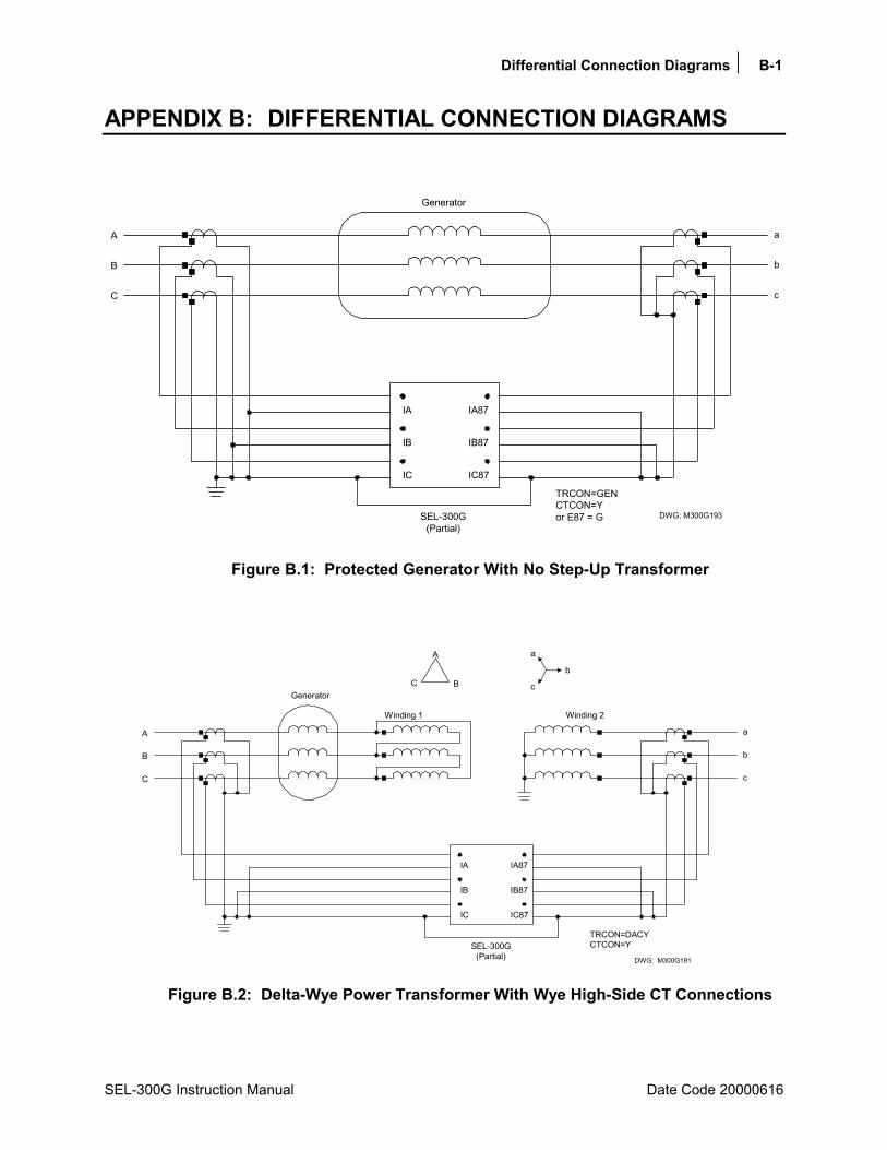
Differential Connection Diagrams B-1
SEL-300G Instruction Manual Date Code 20000616
APPENDIX B: DIFFERENTIAL CONNECTION DIAGRAMS
A
B
C
a
c
b
IA
IB
IC IC87
IB87
IA87
TRCON=GENCTCON=Yor E87 = G
Generator
SEL-300G(Partial)
DWG: M300G193
Figure B.1: Protected Generator With No Step-Up Transformer
A
B
C
a
c
b
IA
IB
IC IC87
IB87
IA87
TRCON=DACYCTCON=YSEL-300G
(Partial)
A
BC
a
c
b
Winding 1 Winding 2
Generator
DWG: M300G191
Figure B.2: Delta-Wye Power Transformer With Wye High-Side CT Connections

B-2 Differential Connection Diagrams
Date Code 20000616 SEL-300G Instruction Manual
A
B
C
a
c
b
IA
IB
IC IC87
IB87
IA87
TRCON=DABYCTCON=YSEL-300G
(Partial)
A
BC
a
c
b
Winding 1 Winding 2
DWG: M300G190
Generator
Figure B.3: Delta-Wye Power Transformer With Wye High-Side CT Connections
A
BC
A
B
C
a
c
b
a
c
b
Winding 1 Winding 2
IA
IB
IC IC87
IB87
IA87
TRCON=DACYCTCON=DAC
SEL-300G(Partial)
DWG: M300G188
Generator
Figure B.4: Delta-Wye Power Transformer With Delta High-Side CT Connections

Differential Connection Diagrams B-3
SEL-300G Instruction Manual Date Code 20000616
A
BC
A
B
C
a
c
b
a
c
b
Winding 1 Winding 2
IA
IB
IC IC87
IB87
IA87
TRCON=DABYCTCON=DAB
SEL-300G(Partial)
Generator
DWG: M300G196
Figure B.5: Delta-Wye Power Transformer With Delta High-Side CT Connections
A
B
C
a
c
b
Winding 1 Winding 2
IA
IB
IC IC87
IB87
IA87
TRCON=DACDACCTCON=YSEL-300G
(Partial)
C
A
B c b
a
Generator
DWG: M300G187
Figure B.6: Delta-Delta Power Transformer With Wye High-Side CT Connections
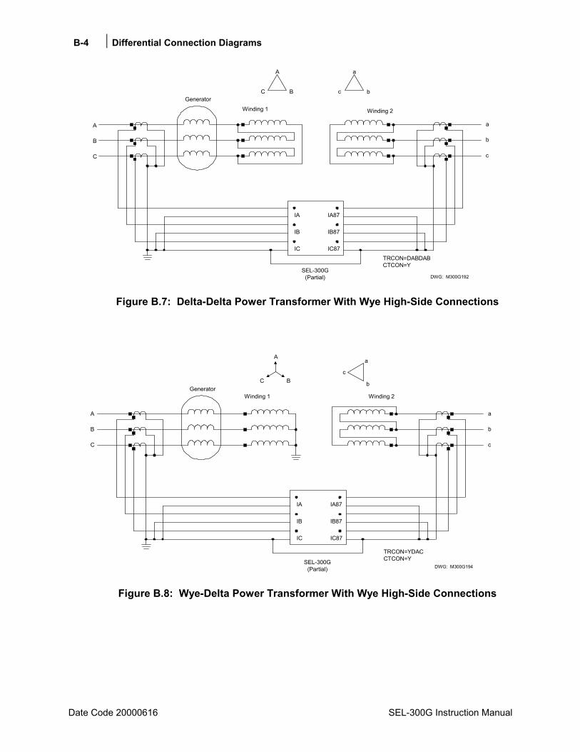
B-4 Differential Connection Diagrams
Date Code 20000616 SEL-300G Instruction Manual
A
B
C
a
c
b
Winding 1 Winding 2
IA
IB
IC IC87
IB87
IA87
TRCON=DABDABCTCON=Y
SEL-300G(Partial)
C
A
B c b
a
DWG: M300G192
Generator
Figure B.7: Delta-Delta Power Transformer With Wye High-Side Connections
A
B
C
a
c
b
IA
IB
IC IC87
IB87
IA87
TRCON=YDACCTCON=YSEL-300G
(Partial)
Winding 1
C B
A
c
Winding 2
b
a
DWG: M300G194
Generator
Figure B.8: Wye-Delta Power Transformer With Wye High-Side Connections
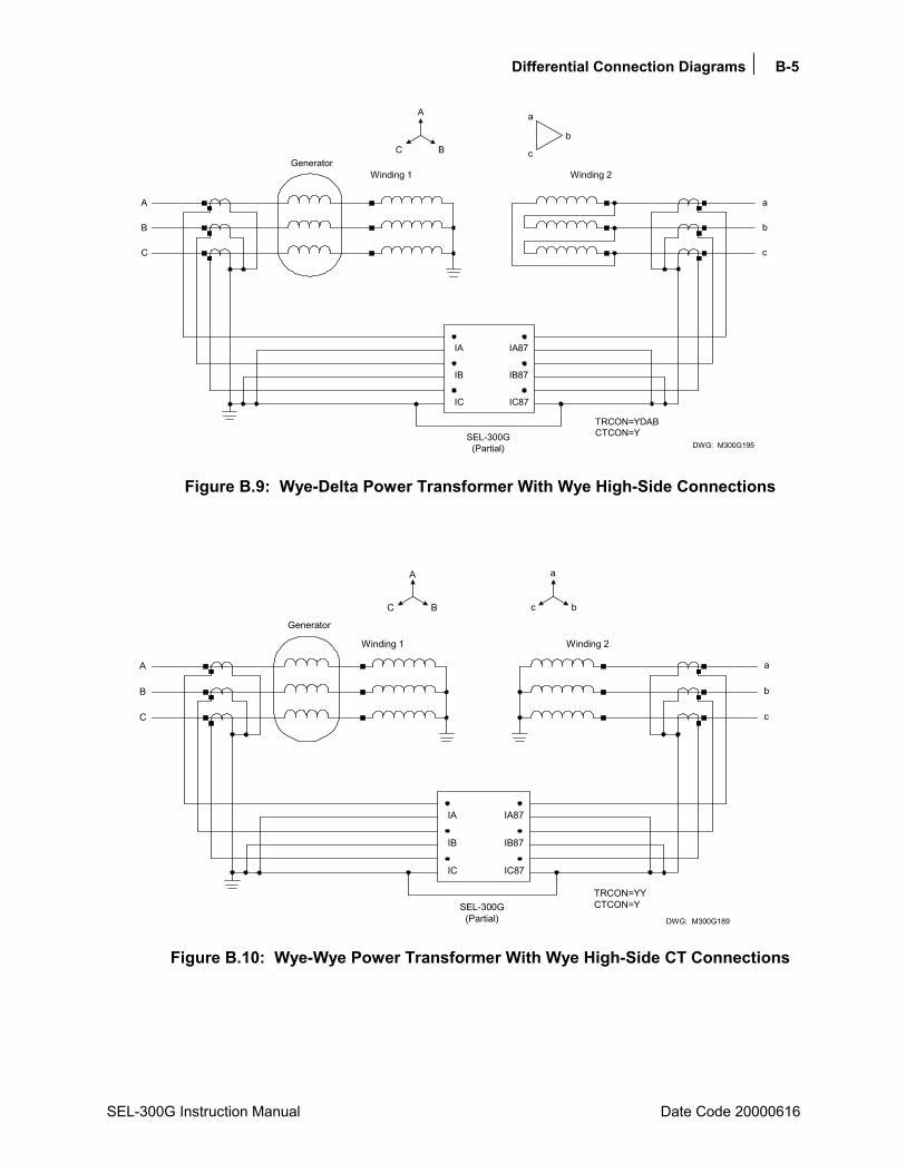
Differential Connection Diagrams B-5
SEL-300G Instruction Manual Date Code 20000616
A
B
C
a
c
b
IA
IB
IC IC87
IB87
IA87
TRCON=YDABCTCON=YSEL-300G
(Partial)
Winding 1
C B
A
c
Winding 2
b
a
Generator
DWG: M300G195
Figure B.9: Wye-Delta Power Transformer With Wye High-Side Connections
A
B
C
a
c
b
IA
IB
IC IC87
IB87
IA87
TRCON=YYCTCON=YSEL-300G
(Partial)
Winding 1
C B
A
c
a
Winding 2
b
Generator
DWG: M300G189
Figure B.10: Wye-Wye Power Transformer With Wye High-Side CT Connections

SEL Distributed Port Switch Protocol C-1
SEL-300G Instruction Manual Date Code 20000616
APPENDIX C: SEL DISTRIBUTED PORT SWITCH PROTOCOL
SEL Distributed Port Switch Protocol (LMD) permits multiple SEL relays to share a common communications channel. It is appropriate for low-cost, low-speed port switching applications where updating a real-time database is not a requirement.
SETTINGS Use the front-panel SET pushbutton or the serial port SET P command to activate the LMD protocol. Change the port PROTO setting from the default SEL to LMD to reveal the following settings:
PREFIX: One character to precede the address. This should be a character that does not occur in the course of other communications with the relay. Valid choices are one of the following: @, #, $, %, &. The default is @.
ADDR: Two-character ASCII address. The range is 01 to 99. The default is 01.SETTLE: Time in seconds that transmission is delayed after the request to send (RTS
line) asserts. This delay accommodates transmitters with a slow rise time.
OPERATION 1. The relay ignores all input from this port until it detects the prefix character and the two-byte
address.
2. Upon receipt of the prefix and address, the relay enables echo and message transmission.
3. Wait until you receive a prompt before entering commands to avoid losing echoed characters while the external transmitter is warming up.
4. Until the relay connection terminates, you can use the standard commands that are available when PROTO is set to SEL.
5. The QUIT command terminates the connection. If no data are sent to the relay before the port timeup period, it automatically terminates the connection.
6. Enter the sequence CTRL-X QUIT <CR> before entering the prefix character if all relays in the multidrop network do not have the same prefix setting.
Note: You can use the front-panel SET pushbutton to change the port settings to return to SEL protocol.

Configuration, Fast Meter, and Fast Operate Commands D-1
SEL-300G Instruction Manual Date Code 20000616
APPENDIX D: CONFIGURATION, FAST METER, AND FAST OPERATE COMMANDS
INTRODUCTION SEL relays have two separate data streams that share the same serial port. The human data communications with the relay consist of ASCII character commands and reports that are intelligible to humans using a terminal or terminal emulation package. The binary data streams can interrupt the ASCII data stream to obtain information and then allow the ASCII data stream to continue. This mechanism allows a single communications channel to be used for ASCII communications (e.g., transmission of a long event report) interleaved with short bursts of binary data to support fast acquisition of metering data. The device connected to the other end of the link requires software that uses the separate data streams to exploit this feature. The binary commands and ASCII commands can also be accessed by a device that does not interleave the data streams.
SEL Application Guide AG95-10, Configuration and Fast Meter Messages, is a comprehensive description of the SEL binary messages. Below is a description of the messages provided in the SEL-300G Relay.
MESSAGE LISTS
Binary Message List Request to Relay (hex) Response From Relay
A5C0 Relay Definition Block A5C1 Fast Meter Configuration Block A5D1 Fast Meter Data Block A5C2 Demand Fast Meter Configuration Block A5D2 Demand Fast Meter Data Message A5C3 Peak Demand Fast Meter Configuration Block A5D3 Peak Demand Fast Meter Data Message A5B9 Fast Meter Status Acknowledge A5CE Fast Operate Configuration Block A5E0 Fast Operate Remote Bit Control A5E3 Fast Operate Breaker Control
ASCII Configuration Message List Request to Relay (ASCII) Response From Relay
ID ASCII Firmware ID String and Terminal ID Setting (TID) DNA ASCII Names of Relay Word bits BNA ASCII Names of bits in the A5B9 Status Byte

D-2 Configuration, Fast Meter, and Fast Operate Commands
Date Code 20020206 SEL-300G Instruction Manual
MESSAGE DEFINITIONS
A5C0 Relay Definition Block
In response to the A5C0 request, the relay sends the following block: Data Description A5C0 Command 42 Length 03 Support three protocols, SEL, LMD, and MOD 03 Support three Fast Meter messages 05 Support five status flag commands A5C1 Fast Meter configuration command A5D1 Fast Meter command A5C2 Demand Fast Meter configuration command A5D2 Demand Fast Meter command A5C3 Peak Demand Fast Meter configuration command A5D3 Peak Demand Fast Meter command 0004 Settings change bit A5C100000000 Fast Meter configuration message 0004 Settings change bit A5C200000000 Demand Fast Meter configuration message 0004 Settings change bit A5C300000000 Peak Demand Fast Meter configuration message 0004 Settings change bit 444E410D0000 DNA command 0004 Settings change bit 49440D000000 ID command 0100 SEL protocol, Fast Operate 0101 LMD protocol, Fast Operate 0002 Modbus protocol 00 Reserved checksum 1-byte checksum of preceding bytes
A5C1 Fast Meter Configuration Block
In response to the A5C1 request, SEL-300G0 Relays send the following block: Data Description A5C1 Fast Meter command 84 Length 01 One status flag byte 00 Scale factors in Fast Meter message 00 No scale factors 0A # of analog input channels 02 # of samples per channel 36 # of digital banks 01 # of calculation blocks 0004 Analog channel offset
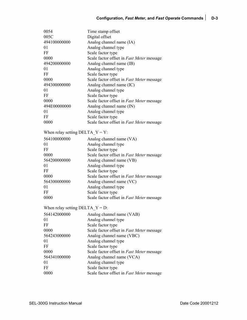
Configuration, Fast Meter, and Fast Operate Commands D-3
SEL-300G Instruction Manual Date Code 20001212
0054 Time stamp offset 005C Digital offset 494100000000 Analog channel name (IA) 01 Analog channel type FF Scale factor type 0000 Scale factor offset in Fast Meter message 494200000000 Analog channel name (IB) 01 Analog channel type FF Scale factor type 0000 Scale factor offset in Fast Meter message 494300000000 Analog channel name (IC) 01 Analog channel type FF Scale factor type 0000 Scale factor offset in Fast Meter message 494E00000000 Analog channel name (IN) 01 Analog channel type FF Scale factor type 0000 Scale factor offset in Fast Meter message
When relay setting DELTA_Y = Y: 564100000000 Analog channel name (VA) 01 Analog channel type FF Scale factor type 0000 Scale factor offset in Fast Meter message 564200000000 Analog channel name (VB) 01 Analog channel type FF Scale factor type 0000 Scale factor offset in Fast Meter message 564300000000 Analog channel name (VC) 01 Analog channel type FF Scale factor type 0000 Scale factor offset in Fast Meter message
When relay setting DELTA_Y = D: 564142000000 Analog channel name (VAB) 01 Analog channel type FF Scale factor type 0000 Scale factor offset in Fast Meter message 564243000000 Analog channel name (VBC) 01 Analog channel type FF Scale factor type 0000 Scale factor offset in Fast Meter message 564341000000 Analog channel name (VCA) 01 Analog channel type FF Scale factor type 0000 Scale factor offset in Fast Meter message
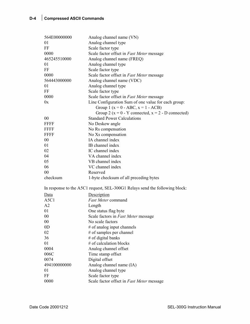
D-4 Compressed ASCII Commands
Date Code 20001212 SEL-300G Instruction Manual
564E00000000 Analog channel name (VN) 01 Analog channel type FF Scale factor type 0000 Scale factor offset in Fast Meter message 465245510000 Analog channel name (FREQ) 01 Analog channel type FF Scale factor type 0000 Scale factor offset in Fast Meter message 564443000000 Analog channel name (VDC) 01 Analog channel type FF Scale factor type 0000 Scale factor offset in Fast Meter message 0x Line Configuration Sum of one value for each group: Group 1 (x = 0 - ABC, x = 1 - ACB) Group 2 (x = 0 - Y connected, x = 2 - D connected) 00 Standard Power Calculations FFFF No Deskew angle FFFF No Rs compensation FFFF No Xs compensation 00 IA channel index 01 IB channel index 02 IC channel index 04 VA channel index 05 VB channel index 06 VC channel index 00 Reserved checksum 1-byte checksum of all preceding bytes
In response to the A5C1 request, SEL-300G1 Relays send the following block: Data Description A5C1 Fast Meter command A2 Length 01 One status flag byte 00 Scale factors in Fast Meter message 00 No scale factors 0D # of analog input channels 02 # of samples per channel 36 # of digital banks 01 # of calculation blocks 0004 Analog channel offset 006C Time stamp offset 0074 Digital offset 494100000000 Analog channel name (IA) 01 Analog channel type FF Scale factor type 0000 Scale factor offset in Fast Meter message
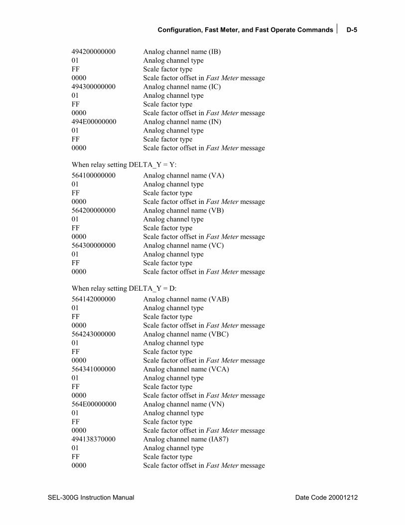
Configuration, Fast Meter, and Fast Operate Commands D-5
SEL-300G Instruction Manual Date Code 20001212
494200000000 Analog channel name (IB) 01 Analog channel type FF Scale factor type 0000 Scale factor offset in Fast Meter message 494300000000 Analog channel name (IC) 01 Analog channel type FF Scale factor type 0000 Scale factor offset in Fast Meter message 494E00000000 Analog channel name (IN) 01 Analog channel type FF Scale factor type 0000 Scale factor offset in Fast Meter message
When relay setting DELTA_Y = Y: 564100000000 Analog channel name (VA) 01 Analog channel type FF Scale factor type 0000 Scale factor offset in Fast Meter message 564200000000 Analog channel name (VB) 01 Analog channel type FF Scale factor type 0000 Scale factor offset in Fast Meter message 564300000000 Analog channel name (VC) 01 Analog channel type FF Scale factor type 0000 Scale factor offset in Fast Meter message
When relay setting DELTA_Y = D: 564142000000 Analog channel name (VAB) 01 Analog channel type FF Scale factor type 0000 Scale factor offset in Fast Meter message 564243000000 Analog channel name (VBC) 01 Analog channel type FF Scale factor type 0000 Scale factor offset in Fast Meter message 564341000000 Analog channel name (VCA) 01 Analog channel type FF Scale factor type 0000 Scale factor offset in Fast Meter message 564E00000000 Analog channel name (VN) 01 Analog channel type FF Scale factor type 0000 Scale factor offset in Fast Meter message 494138370000 Analog channel name (IA87) 01 Analog channel type FF Scale factor type 0000 Scale factor offset in Fast Meter message

D-6 Compressed ASCII Commands
Date Code 20001212 SEL-300G Instruction Manual
494238370000 Analog channel name (IB87) 01 Analog channel type FF Scale factor type 0000 Scale factor offset in Fast Meter message 494338370000 Analog channel name (IC87) 01 Analog channel type FF Scale factor type 0000 Scale factor offset in Fast Meter message 465245510000 Analog channel name (FREQ) 01 Analog channel type FF Scale factor type 0000 Scale factor offset in Fast Meter message 564443000000 Analog channel name (VDC) 01 Analog channel type FF Scale factor type 0000 Scale factor offset in Fast Meter message 0x Line Configuration Sum of one value for each group: Group 1 (x = 0 - ABC, x = 1 - ACB) Group 2 (x = 0 - Y connected, x = 2 - D connected) 00 Standard Power Calculations FFFF No Deskew angle FFFF No Rs compensation FFFF No Xs compensation 00 IA channel index 01 IB channel index 02 IC channel index 04 VA channel index 05 VB channel index 06 VC channel index 00 Reserved checksum 1-byte checksum of all preceding bytes
In response to the A5C1 request, SEL-300G2 Relays send the following block: Data Description A5C1 Fast Meter command 8E Length 01 One status flag byte 00 Scale factors in Fast Meter message 00 No scale factors 0B # of analog input channels 02 # of samples per channel 36 # of digital banks 01 # of calculation blocks 0004 Analog channel offset 005C Time stamp offset 0064 Digital offset
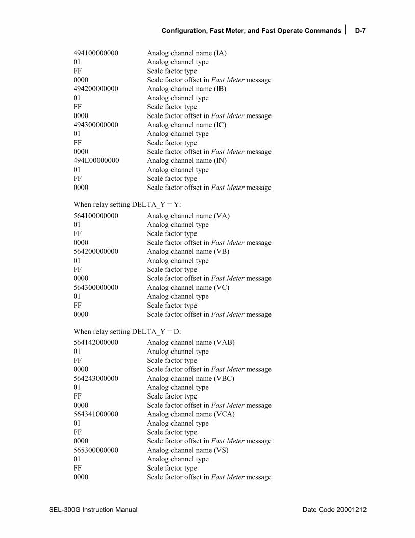
Configuration, Fast Meter, and Fast Operate Commands D-7
SEL-300G Instruction Manual Date Code 20001212
494100000000 Analog channel name (IA) 01 Analog channel type FF Scale factor type 0000 Scale factor offset in Fast Meter message 494200000000 Analog channel name (IB) 01 Analog channel type FF Scale factor type 0000 Scale factor offset in Fast Meter message 494300000000 Analog channel name (IC) 01 Analog channel type FF Scale factor type 0000 Scale factor offset in Fast Meter message 494E00000000 Analog channel name (IN) 01 Analog channel type FF Scale factor type 0000 Scale factor offset in Fast Meter message
When relay setting DELTA_Y = Y: 564100000000 Analog channel name (VA) 01 Analog channel type FF Scale factor type 0000 Scale factor offset in Fast Meter message 564200000000 Analog channel name (VB) 01 Analog channel type FF Scale factor type 0000 Scale factor offset in Fast Meter message 564300000000 Analog channel name (VC) 01 Analog channel type FF Scale factor type 0000 Scale factor offset in Fast Meter message
When relay setting DELTA_Y = D: 564142000000 Analog channel name (VAB) 01 Analog channel type FF Scale factor type 0000 Scale factor offset in Fast Meter message 564243000000 Analog channel name (VBC) 01 Analog channel type FF Scale factor type 0000 Scale factor offset in Fast Meter message 564341000000 Analog channel name (VCA) 01 Analog channel type FF Scale factor type 0000 Scale factor offset in Fast Meter message 565300000000 Analog channel name (VS) 01 Analog channel type FF Scale factor type 0000 Scale factor offset in Fast Meter message
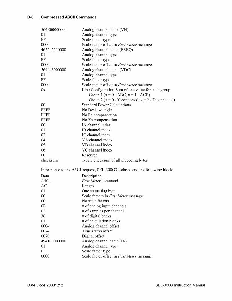
D-8 Compressed ASCII Commands
Date Code 20001212 SEL-300G Instruction Manual
564E00000000 Analog channel name (VN) 01 Analog channel type FF Scale factor type 0000 Scale factor offset in Fast Meter message 465245510000 Analog channel name (FREQ) 01 Analog channel type FF Scale factor type 0000 Scale factor offset in Fast Meter message 564443000000 Analog channel name (VDC) 01 Analog channel type FF Scale factor type 0000 Scale factor offset in Fast Meter message 0x Line Configuration Sum of one value for each group: Group 1 (x = 0 - ABC, x = 1 - ACB) Group 2 (x = 0 - Y connected, x = 2 - D connected) 00 Standard Power Calculations FFFF No Deskew angle FFFF No Rs compensation FFFF No Xs compensation 00 IA channel index 01 IB channel index 02 IC channel index 04 VA channel index 05 VB channel index 06 VC channel index 00 Reserved checksum 1-byte checksum of all preceding bytes
In response to the A5C1 request, SEL-300G3 Relays send the following block: Data Description A5C1 Fast Meter command AC Length 01 One status flag byte 00 Scale factors in Fast Meter message 00 No scale factors 0E # of analog input channels 02 # of samples per channel 36 # of digital banks 01 # of calculation blocks 0004 Analog channel offset 0074 Time stamp offset 007C Digital offset 494100000000 Analog channel name (IA) 01 Analog channel type FF Scale factor type 0000 Scale factor offset in Fast Meter message

Configuration, Fast Meter, and Fast Operate Commands D-9
SEL-300G Instruction Manual Date Code 20001212
494200000000 Analog channel name (IB) 01 Analog channel type FF Scale factor type 0000 Scale factor offset in Fast Meter message 494300000000 Analog channel name (IC) 01 Analog channel type FF Scale factor type 0000 Scale factor offset in Fast Meter message 494E00000000 Analog channel name (IN) 01 Analog channel type FF Scale factor type 0000 Scale factor offset in Fast Meter message
When relay setting DELTA_Y = Y: 564100000000 Analog channel name (VA) 01 Analog channel type FF Scale factor type 0000 Scale factor offset in Fast Meter message 564200000000 Analog channel name (VB) 01 Analog channel type FF Scale factor type 0000 Scale factor offset in Fast Meter message 564300000000 Analog channel name (VC) 01 Analog channel type FF Scale factor type 0000 Scale factor offset in Fast Meter message
When relay setting DELTA_Y = D: 564142000000 Analog channel name (VAB) 01 Analog channel type FF Scale factor type 0000 Scale factor offset in Fast Meter message 564243000000 Analog channel name (VBC) 01 Analog channel type FF Scale factor type 0000 Scale factor offset in Fast Meter message 564341000000 Analog channel name (VCA) 01 Analog channel type FF Scale factor type 0000 Scale factor offset in Fast Meter message 565300000000 Analog channel name (VS) 01 Analog channel type FF Scale factor type 0000 Scale factor offset in Fast Meter message 564E00000000 Analog channel name (VN) 01 Analog channel type FF Scale factor type 0000 Scale factor offset in Fast Meter message

D-10 Compressed ASCII Commands
Date Code 20001212 SEL-300G Instruction Manual
494138370000 Analog channel name (IA87) 01 Analog channel type FF Scale factor type 0000 Scale factor offset in Fast Meter message 494238370000 Analog channel name (IB87) 01 Analog channel type FF Scale factor type 0000 Scale factor offset in Fast Meter message 494338370000 Analog channel name (IC87) 01 Analog channel type FF Scale factor type 0000 Scale factor offset in Fast Meter message 465245510000 Analog channel name (FREQ) 01 Analog channel type FF Scale factor type 0000 Scale factor offset in Fast Meter message 564443000000 Analog channel name (VDC) 01 Analog channel type FF Scale factor type 0000 Scale factor offset in Fast Meter message 0x Line Configuration Sum of one value for each group: Group 1 (x = 0 - ABC, x = 1 - ACB) Group 2 (x = 0 - Y connected, x = 2 - D connected) 00 Standard Power Calculations FFFF No Deskew angle FFFF No Rs compensation FFFF No Xs compensation 00 IA channel index 01 IB channel index 02 IC channel index 04 VA channel index 05 VB channel index 06 VC channel index 00 Reserved checksum 1-byte checksum of all preceding bytes
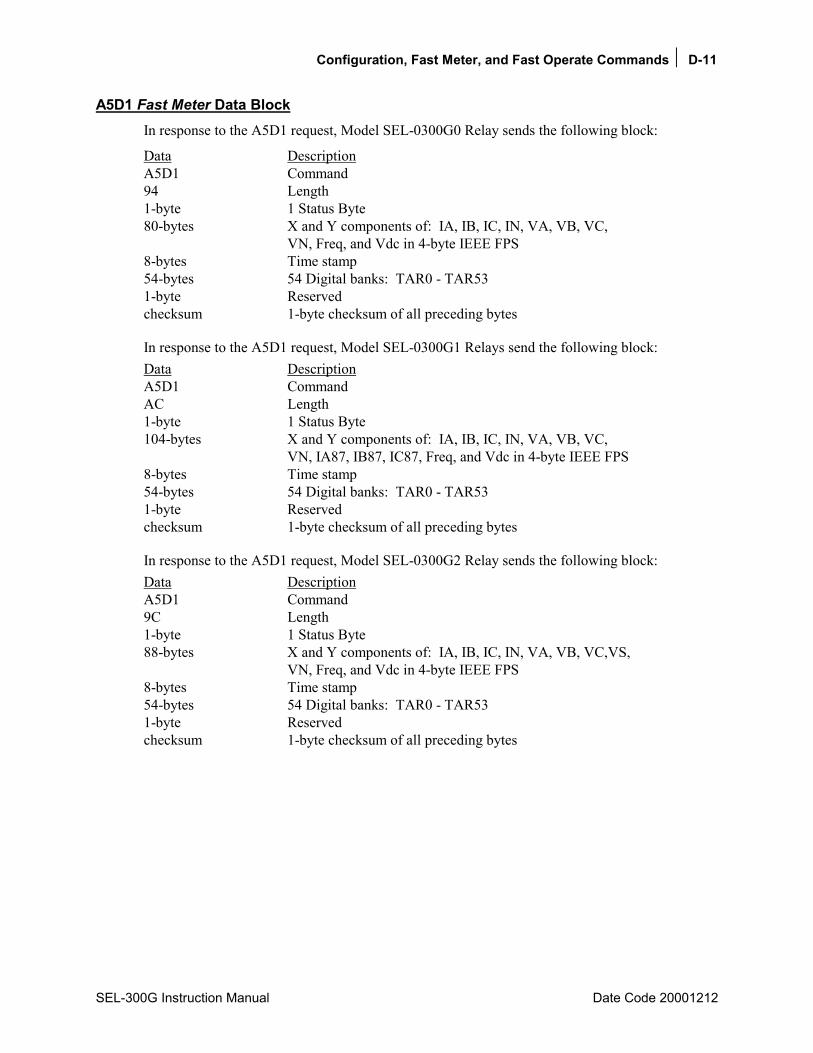
Configuration, Fast Meter, and Fast Operate Commands D-11
SEL-300G Instruction Manual Date Code 20001212
A5D1 Fast Meter Data Block In response to the A5D1 request, Model SEL-0300G0 Relay sends the following block:
Data Description A5D1 Command 94 Length 1-byte 1 Status Byte 80-bytes X and Y components of: IA, IB, IC, IN, VA, VB, VC, VN, Freq, and Vdc in 4-byte IEEE FPS 8-bytes Time stamp 54-bytes 54 Digital banks: TAR0 - TAR53 1-byte Reserved checksum 1-byte checksum of all preceding bytes
In response to the A5D1 request, Model SEL-0300G1 Relays send the following block: Data Description A5D1 Command AC Length 1-byte 1 Status Byte 104-bytes X and Y components of: IA, IB, IC, IN, VA, VB, VC, VN, IA87, IB87, IC87, Freq, and Vdc in 4-byte IEEE FPS 8-bytes Time stamp 54-bytes 54 Digital banks: TAR0 - TAR53 1-byte Reserved checksum 1-byte checksum of all preceding bytes
In response to the A5D1 request, Model SEL-0300G2 Relay sends the following block: Data Description A5D1 Command 9C Length 1-byte 1 Status Byte 88-bytes X and Y components of: IA, IB, IC, IN, VA, VB, VC,VS, VN, Freq, and Vdc in 4-byte IEEE FPS 8-bytes Time stamp 54-bytes 54 Digital banks: TAR0 - TAR53 1-byte Reserved checksum 1-byte checksum of all preceding bytes
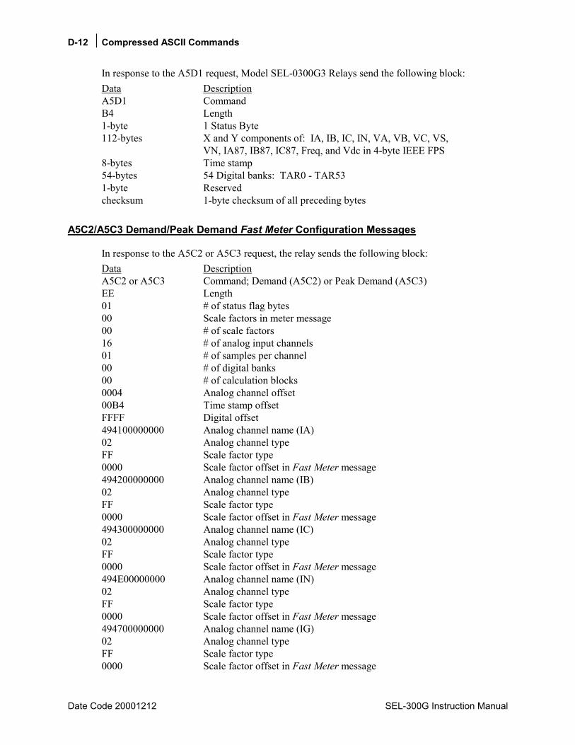
D-12 Compressed ASCII Commands
Date Code 20001212 SEL-300G Instruction Manual
In response to the A5D1 request, Model SEL-0300G3 Relays send the following block: Data Description A5D1 Command B4 Length 1-byte 1 Status Byte 112-bytes X and Y components of: IA, IB, IC, IN, VA, VB, VC, VS, VN, IA87, IB87, IC87, Freq, and Vdc in 4-byte IEEE FPS 8-bytes Time stamp 54-bytes 54 Digital banks: TAR0 - TAR53 1-byte Reserved checksum 1-byte checksum of all preceding bytes
A5C2/A5C3 Demand/Peak Demand Fast Meter Configuration Messages
In response to the A5C2 or A5C3 request, the relay sends the following block: Data Description A5C2 or A5C3 Command; Demand (A5C2) or Peak Demand (A5C3) EE Length 01 # of status flag bytes 00 Scale factors in meter message 00 # of scale factors 16 # of analog input channels 01 # of samples per channel 00 # of digital banks 00 # of calculation blocks 0004 Analog channel offset 00B4 Time stamp offset FFFF Digital offset 494100000000 Analog channel name (IA) 02 Analog channel type FF Scale factor type 0000 Scale factor offset in Fast Meter message 494200000000 Analog channel name (IB) 02 Analog channel type FF Scale factor type 0000 Scale factor offset in Fast Meter message 494300000000 Analog channel name (IC) 02 Analog channel type FF Scale factor type 0000 Scale factor offset in Fast Meter message 494E00000000 Analog channel name (IN) 02 Analog channel type FF Scale factor type 0000 Scale factor offset in Fast Meter message 494700000000 Analog channel name (IG) 02 Analog channel type FF Scale factor type 0000 Scale factor offset in Fast Meter message

Configuration, Fast Meter, and Fast Operate Commands D-13
SEL-300G Instruction Manual Date Code 20001212
334932000000 Analog channel name (3I2) 02 Analog channel type FF Scale factor type 0000 Scale factor offset in Fast Meter message 50412B000000 Analog channel name (PA+) 02 Analog channel type FF Scale factor type 0000 Scale factor offset in Fast Meter message 50422B000000 Analog channel name (PB+) 02 Analog channel type FF Scale factor type 0000 Scale factor offset in Fast Meter message 50432B000000 Analog channel name (PC+) 02 Analog channel type FF Scale factor type 0000 Scale factor offset in Fast Meter message 50332B000000 Analog channel name (P3+) 02 Analog channel type FF Scale factor type 0000 Scale factor offset in Fast Meter message 51412B000000 Analog channel name (QA+) 02 Analog channel type FF Scale factor type 0000 Scale factor offset in Fast Meter message 51422B000000 Analog channel name (QB+) 02 Analog channel type FF Scale factor type 0000 Scale factor offset in Fast Meter message 51432B000000 Analog channel name (QC+) 02 Analog channel type FF Scale factor type 0000 Scale factor offset in Fast Meter message 51332B000000 Analog channel name (Q3+) 02 Analog channel type FF Scale factor type 0000 Scale factor offset in Fast Meter message 50412D000000 Analog channel name (PA-) 02 Analog channel type FF Scale factor type 0000 Scale factor offset in Fast Meter message 50422D000000 Analog channel name (PB-) 02 Analog channel type FF Scale factor type 0000 Scale factor offset in Fast Meter message 50432D000000 Analog channel name (PC-) 02 Analog channel type FF Scale factor type 0000 Scale factor offset in Fast Meter message

D-14 Compressed ASCII Commands
Date Code 20001212 SEL-300G Instruction Manual
50332D000000 Analog channel name (P3-) 02 Analog channel type FF Scale factor type 0000 Scale factor offset in Fast Meter message 51412D000000 Analog channel name (QA-) 02 Analog channel type FF Scale factor type 0000 Scale factor offset in Fast Meter message 51422D000000 Analog channel name (QB-) 02 Analog channel type FF Scale factor type 0000 Scale factor offset in Fast Meter message 51432D000000 Analog channel name (QC-) 02 Analog channel type FF Scale factor type 0000 Scale factor offset in Fast Meter message 51332D000000 Analog channel name (Q3-) 02 Analog channel type FF Scale factor type 0000 Scale factor offset in Fast Meter message 00 Reserved checksum 1-byte checksum of preceding bytes
A5D2/A5D3 Demand/Peak Demand Fast Meter Message In response to the A5D2 or A5D3 request, the relay sends the following block:
Data Description A5D2 or A5D3 Command BE Length 1-byte 1 Status Byte 176-bytes Demand: IA, IB, IC, IN, IG, 3I2, MWA I, MWB I, MWC I, MW3PI, MVA I, MVB I, MVC I, MV3PI, MWA O, MWB O, MWC O, MW3PO, MVA O, MVB O, MVC O, MV3PO in 8-byte IEEE FPS 8-bytes Time stamp 1-byte Reserved 1-byte 1-byte checksum of all preceding bytes
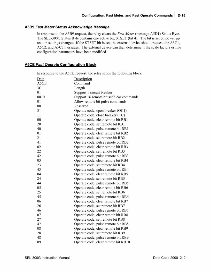
Configuration, Fast Meter, and Fast Operate Commands D-15
SEL-300G Instruction Manual Date Code 20001212
A5B9 Fast Meter Status Acknowledge Message In response to the A5B9 request, the relay clears the Fast Meter (message A5D1) Status Byte. The SEL-300G Status Byte contains one active bit, STSET (bit 4). The bit is set on power up and on settings changes. If the STSET bit is set, the external device should request the A5C1, A5C2, and A5C3 messages. The external device can then determine if the scale factors or line configuration parameters have been modified.
A5CE Fast Operate Configuration Block
In response to the A5CE request, the relay sends the following block: Data Description A5CE Command 3C Length 01 Support 1 circuit breaker 0010 Support 16 remote bit set/clear commands 01 Allow remote bit pulse commands 00 Reserved 31 Operate code, open breaker (OC1) 11 Operate code, close breaker (CC) 00 Operate code, clear remote bit RB1 20 Operate code, set remote bit RB1 40 Operate code, pulse remote bit RB1 01 Operate code, clear remote bit RB2 21 Operate code, set remote bit RB2 41 Operate code, pulse remote bit RB2 02 Operate code, clear remote bit RB3 22 Operate code, set remote bit RB3 42 Operate code, pulse remote bit RB3 03 Operate code, clear remote bit RB4 23 Operate code, set remote bit RB4 43 Operate code, pulse remote bit RB4 04 Operate code, clear remote bit RB5 24 Operate code, set remote bit RB5 44 Operate code, pulse remote bit RB5 05 Operate code, clear remote bit RB6 25 Operate code, set remote bit RB6 45 Operate code, pulse remote bit RB6 06 Operate code, clear remote bit RB7 26 Operate code, set remote bit RB7 46 Operate code, pulse remote bit RB7 07 Operate code, clear remote bit RB8 27 Operate code, set remote bit RB8 47 Operate code, pulse remote bit RB8 08 Operate code, clear remote bit RB9 28 Operate code, set remote bit RB9 48 Operate code, pulse remote bit RB9 09 Operate code, clear remote bit RB10

D-16 Compressed ASCII Commands
Date Code 20001212 SEL-300G Instruction Manual
29 Operate code, set remote bit RB10 49 Operate code, pulse remote bit RB10 0A Operate code, clear remote bit RB11 2A Operate code, set remote bit RB11 4A Operate code, pulse remote bit RB11 0B Operate code, clear remote bit RB12 2B Operate code, set remote bit RB12 4B Operate code, pulse remote bit RB12 0C Operate code, clear remote bit RB13 2C Operate code, set remote bit RB13 4C Operate code, pulse remote bit RB13 0D Operate code, clear remote bit RB14 2D Operate code, set remote bit RB14 4D Operate code, pulse remote bit RB14 0E Operate code, clear remote bit RB15 2E Operate code, set remote bit RB15 4E Operate code, pulse remote bit RB15 0F Operate code, clear remote bit RB16 2F Operate code, set remote bit RB16 4F Operate code, pulse remote bit RB16 00 Reserved checksum 1-byte checksum of all preceding bytes
A5E0 Fast Operate Remote Bit Control The external device sends the following message to perform a remote bit operation:
Data Description A5E0 Command 06 Length 1-byte Operate code:
000F clear remote bit RB1 - RB16 202F set remote bit RB1 - RB16 404F pulse remote bit for RB1 - RB16 for one processing interval
1-byte Operate validation: 4 ⋅ Operate code + 1 checksum 1-byte checksum of preceding bytes
The relay performs the specified remote bit operation if the following conditions are true:
1. The Operate code is valid. 2. The Operate validation = 4 ⋅ Operate code + 1. 3. The message checksum is valid. 4. The FASTOP port setting is set to Y. 5. The relay is enabled.
Remote bit set and clear operations are latched by the relay. Remote bit pulse operations assert the remote bit for one processing interval (1/4 cycle).
It is common practice to route remote bits to output contacts to provide remote control of the relay outputs. If you wish to pulse an output contact closed for a specific duration, SEL recommends using the remote bit pulse command and SELOGIC® Control Equations to provide
Configuration, Fast Meter, and Fast Operate Commands D-17
SEL-300G Instruction Manual Date Code 20001212
secure and accurate contact control. The remote device sends the remote bit pulse command; the relay controls the timing of the output contact assertion. You can use any remote bit (RB1 through RB16) and any SELOGIC Control Equation timer (SV1 through SV16) to control any of the output contacts (OUT101 through OUT107). For example, to pulse output contact OUT104 for 30 cycles with Remote Bit RB4 and SELOGIC Control Equation timer SV4, issue the following relay settings:
via the SET L command, SV4 = RB4 SV4 input is RB4 OUT104 = SV4T route SV4 timer output to OUT104
via the SET command, SV4PU = 0 SV4 pickup time = 0 V4DO = 30 SV4 dropout time is 30 cycles
To pulse the contact, send the A5E006430DDB command to the relay.
A5E3 Fast Operate Breaker Control The external device sends the following message to perform a fast breaker open/close:
Data Description A5E3 Command 06 Length 1-byte Operate code: 31- OPEN breaker (OC1) 11- CLOSE breaker 1-byte Operate Validation: 4 ⋅ Operate code + 1 checksum 1-byte checksum of preceding bytes
The relay performs the specified breaker operation if the following conditions are true:
1. Conditions 1 - 5 defined in the A5E0 message are true. 2. The breaker jumper (JMP6B) is in place on the SEL-300G Relay main board.
ID Message In response to the ID command, the relay sends the firmware ID, relay TID setting, and the Modbus® device code as described below.
<STX>"FID STRING ENCLOSED IN QUOTES","yyyy"<CR> "TID SETTING ENCLOSED IN QUOTES","yyyy"<CR> 33, "yyyy"<CR> <ETX> where <STX> is the STX character (02) <ETX> is the ETX character (03) yyyy is the 4-byte ASCII hex representation
of the checksum for each line.
The ID message is available from Access Level 1 and higher.

D-18 Compressed ASCII Commands
Date Code 20001212 SEL-300G Instruction Manual
DNA Message In response to the Access Level 1 DNA command, the relay sends names of the Relay Word bits transmitted in the A5D1 message. The first name is associated with the MSB, the last name with the LSB. Model SEL-0300G00 DNA message is:
<STX>"EN","BKR","LOP","TRIP","21/51V","50","51","N","0983" "24","27/59","32","40","46","64G","81","87","07A8" "24TC","24D1","24D1T","24C2","24C2T","24CR","SS1","SS2","0B3B" "27P1","27P2","27PP1","27V1","59P1","59P2","59G1","59G2","0B2B" "32PTC","32P1","32P1T","32P2","32P2T","59V1","59Q","59PP1","0C01" "40ZTC","40Z1","40Z1T","40Z2","40Z2T","SWING","SG1","SG2","0C5A" "46QTC","46Q1","46Q1T","46Q2","46Q2T","46Q2R","INAD","INADT","0CF7" "78R1","78R2","78Z1","OOSTC","51CTC","51C","51CT","51CR","0BC8" "51GTC","51G","51GT","51GR","51NTC","51N","51NT","51NR","0B7E" "51VTC","51V","51VT","51VR","PDEM","QDEM","GDEM","NDEM","0C3B" "50P1","50P1T","50P2","50P2T","50G1","50G1T","50G2","50G2T","0BE0" "50N1","50N1T","50N2","50N2T","CC","CL","CLOSE","ULCL","0B75" "64GTC","64G1","64G1T","64G2","64G2T","OOS","60LOP","CLEN","0C5E" "BKMON","BCW","BCWA","BCWB","BCWC","FAULT","DCLO","DCHI","0CE3" "81D1","81D2","81D3","81D4","81D5","81D6","3PO","52A","0A3D" "81D1T","81D2T","81D3T","81D4T","81D5T","81D6T","27B81","50L","0C80" "ONLINE","BND1A","BND1T","BND2A","BND2T","BND3A","BND3T","BNDA","0E3D" "TRGTR","BND4A","BND4T","BND5A","BND5T","BND6A","BND6T","BNDT","0E30" "TRIP","TRIP1","TRIP2","TRIP3","TRIP4","OC1","OC2","OC3","0CD1" "TR1","TR2","TR3","TR4","ULTR1","ULTR2","ULTR3","ULTR4","0CC8" "LB1","LB2","LB3","LB4","LB5","LB6","LB7","LB8","0994" "LB9","LB10","LB11","LB12","LB13","LB14","LB15","LB16","0AE5" "RB1","RB2","RB3","RB4","RB5","RB6","RB7","RB8","09C4" "RB9","RB10","RB11","RB12","RB13","RB14","RB15","RB16","0B15" "*","*","*","*","*","*","*","*","04D0" "SV1","SV2","SV3","SV4","SV1T","SV2T","SV3T","SV4T","0BAC" "SV5","SV6","SV7","SV8","SV5T","SV6T","SV7T","SV8T","0BCC" "SV9","SV10","SV11","SV12","SV9T","SV10T","SV11T","SV12T","0CD6" "SV13","SV14","SV15","SV16","SV13T","SV14T","SV15T","SV16T","0D44" "DP8","DP7","DP6","DP5","DP4","DP3","DP2","DP1","09C4" "DP16","DP15","DP14","DP13","DP12","DP11","DP10","DP9","0B15" "ER","OOST","IN106","IN105","IN104","IN103","IN102","IN101","0C61" "ALARM","OUT107","OUT106","OUT105","OUT104","OUT103","OUT102","OUT101", "0FC8" "*","*","*","*","*","*","*","*","04D0" "*","*","*","*","*","*","*","*","04D0" "*","*","*","*","*","*","*","*","04D0" "*","*","*","*","*","*","*","*","04D0" "59PP2","27PP2","*","*","*","*","*","*","06F7" "87NTC","87N1P","87N1T","87N2P","87N2T","*","*","*","0A54" "21PTC","21P1P","21P1T","21P2P","21P2T","*","*","*","0A22" "*","*","*","*","*","*","*","*","04D0" "*","*","*","*","*","*","*","*","04D0" "*","*","*","*","*","*","*","*","04D0"
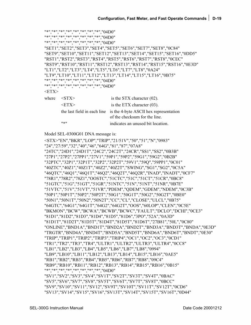
Configuration, Fast Meter, and Fast Operate Commands D-19
SEL-300G Instruction Manual Date Code 20001212
"*","*","*","*","*","*","*","*","04D0" "*","*","*","*","*","*","*","*","04D0" "*","*","*","*","*","*","*","*","04D0" "SET1","SET2","SET3","SET4","SET5","SET6","SET7","SET8","0C84" "SET9","SET10","SET11","SET12","SET13","SET14","SET15","SET16","0DD5" "RST1","RST2","RST3","RST4","RST5","RST6","RST7","RST8","0CEC" "RST9","RST10","RST11","RST12","RST13","RST14","RST15","RST16","0E3D" "LT1","LT2","LT3","LT4","LT5","LT6","LT7","LT8","0A24" "LT9","LT10","LT11","LT12","LT13","LT14","LT15","LT16","0B75" "*","*","*","*","*","*","*","*","04D0" "*","*","*","*","*","*","*","*","04D0" <ETX> where <STX> is the STX character (02). <ETX> is the ETX character (03). the last field in each line is the 4-byte ASCII hex representation
of the checksum for the line. "*" indicates an unused bit location.
Model SEL-0300G01 DNA message is: <STX>"EN","BKR","LOP","TRIP","21/51V","50","51","N","0983" "24","27/59","32","40","46","64G","81","87","07A8" "24TC","24D1","24D1T","24C2","24C2T","24CR","SS1","SS2","0B3B" "27P1","27P2","27PP1","27V1","59P1","59P2","59G1","59G2","0B2B" "32PTC","32P1","32P1T","32P2","32P2T","59V1","59Q","59PP1","0C01" "40ZTC","40Z1","40Z1T","40Z2","40Z2T","SWING","SG1","SG2","0C5A" "46QTC","46Q1","46Q1T","46Q2","46Q2T","46Q2R","INAD","INADT","0CF7" "78R1","78R2","78Z1","OOSTC","51CTC","51C","51CT","51CR","0BC8" "51GTC","51G","51GT","51GR","51NTC","51N","51NT","51NR","0B7E" "51VTC","51V","51VT","51VR","PDEM","QDEM","GDEM","NDEM","0C3B" "50P1","50P1T","50P2","50P2T","50G1","50G1T","50G2","50G2T","0BE0" "50N1","50N1T","50N2","50N2T","CC","CL","CLOSE","ULCL","0B75" "64GTC","64G1","64G1T","64G2","64G2T","OOS","60LOP","CLEN","0C5E" "BKMON","BCW","BCWA","BCWB","BCWC","FAULT","DCLO","DCHI","0CE3" "81D1","81D2","81D3","81D4","81D5","81D6","3PO","52A","0A3D" "81D1T","81D2T","81D3T","81D4T","81D5T","81D6T","27B81","50L","0C80" "ONLINE","BND1A","BND1T","BND2A","BND2T","BND3A","BND3T","BNDA","0E3D" "TRGTR","BND4A","BND4T","BND5A","BND5T","BND6A","BND6T","BNDT","0E30" "TRIP","TRIP1","TRIP2","TRIP3","TRIP4","OC1","OC2","OC3","0CD1" "TR1","TR2","TR3","TR4","ULTR1","ULTR2","ULTR3","ULTR4","0CC8" "LB1","LB2","LB3","LB4","LB5","LB6","LB7","LB8","0994" "LB9","LB10","LB11","LB12","LB13","LB14","LB15","LB16","0AE5" "RB1","RB2","RB3","RB4","RB5","RB6","RB7","RB8","09C4" "RB9","RB10","RB11","RB12","RB13","RB14","RB15","RB16","0B15" "*","*","*","*","*","*","*","*","04D0" "SV1","SV2","SV3","SV4","SV1T","SV2T","SV3T","SV4T","0BAC" "SV5","SV6","SV7","SV8","SV5T","SV6T","SV7T","SV8T","0BCC" "SV9","SV10","SV11","SV12","SV9T","SV10T","SV11T","SV12T","0CD6" "SV13","SV14","SV15","SV16","SV13T","SV14T","SV15T","SV16T","0D44"

D-20 Compressed ASCII Commands
Date Code 20001212 SEL-300G Instruction Manual
"DP8","DP7","DP6","DP5","DP4","DP3","DP2","DP1","09C4" "DP16","DP15","DP14","DP13","DP12","DP11","DP10","DP9","0B15" "ER","OOST","IN106","IN105","IN104","IN103","IN102","IN101","0C61" "ALARM","OUT107","OUT106","OUT105","OUT104","OUT103","OUT102","OUT101", "0FC8" "*","*","*","*","*","*","*","*","04D0" "*","*","*","*","*","*","*","*","04D0" "*","*","*","*","*","*","*","*","04D0" "*","*","*","*","*","*","*","*","04D0" "59PP2","27PP2","*","*","*","*","*","*","06F7" "87NTC","87N1P","87N1T","87N2P","87N2T","*","*","*","0A54" "21PTC","21P1P","21P1T","21P2P","21P2T","*","*","*","0A22" "IN208","IN207","IN206","IN205","IN204","IN203","IN202","IN201","0CEC" "*","*","*","*","*","*","*","*","04D0" "OUT201","OUT202","OUT203","OUT204","OUT205","OUT206","OUT207","OUT208", "0FF4" "OUT209","OUT210","OUT211","OUT212","*","*","*","*","0A5F" "*","*","*","*","*","*","*","*","04D0" "*","*","*","*","*","*","*","*","04D0" "SET1","SET2","SET3","SET4","SET5","SET6","SET7","SET8","0C84" "SET9","SET10","SET11","SET12","SET13","SET14","SET15","SET16","0DD5" "RST1","RST2","RST3","RST4","RST5","RST6","RST7","RST8","0CEC" "RST9","RST10","RST11","RST12","RST13","RST14","RST15","RST16","0E3D" "LT1","LT2","LT3","LT4","LT5","LT6","LT7","LT8","0A24" "LT9","LT10","LT11","LT12","LT13","LT14","LT15","LT16","0B75" "*","*","*","*","*","*","*","*","04D0" "*","*","*","*","*","*","*","*","04D0" <ETX>
Model SEL-0300G10 DNA message is: <STX>"EN","BKR","LOP","TRIP","21/51V","50","51","N","0983" "24","27/59","32","40","46","64G","81","87","07A8" "24TC","24D1","24D1T","24C2","24C2T","24CR","SS1","SS2","0B3B" "27P1","27P2","27PP1","27V1","59P1","59P2","59G1","59G2","0B2B" "32PTC","32P1","32P1T","32P2","32P2T","59V1","59Q","59PP1","0C01" "40ZTC","40Z1","40Z1T","40Z2","40Z2T","SWING","SG1","SG2","0C5A" "46QTC","46Q1","46Q1T","46Q2","46Q2T","46Q2R","INAD","INADT","0CF7" "78R1","78R2","78Z1","OOSTC","51CTC","51C","51CT","51CR","0BC8" "51GTC","51G","51GT","51GR","51NTC","51N","51NT","51NR","0B7E" "51VTC","51V","51VT","51VR","PDEM","QDEM","GDEM","NDEM","0C3B" "50P1","50P1T","50P2","50P2T","50G1","50G1T","50G2","50G2T","0BE0" "50N1","50N1T","50N2","50N2T","CC","CL","CLOSE","ULCL","0B75" "64GTC","64G1","64G1T","64G2","64G2T","OOS","60LOP","CLEN","0C5E" "BKMON","BCW","BCWA","BCWB","BCWC","FAULT","DCLO","DCHI","0CE3" "81D1","81D2","81D3","81D4","81D5","81D6","3PO","52A","0A3D" "81D1T","81D2T","81D3T","81D4T","81D5T","81D6T","27B81","50L","0C80" "ONLINE","BND1A","BND1T","BND2A","BND2T","BND3A","BND3T","BNDA","0E3D" "TRGTR","BND4A","BND4T","BND5A","BND5T","BND6A","BND6T","BNDT","0E30" "TRIP","TRIP1","TRIP2","TRIP3","TRIP4","OC1","OC2","OC3","0CD1"

Configuration, Fast Meter, and Fast Operate Commands D-21
SEL-300G Instruction Manual Date Code 20001212
"TR1","TR2","TR3","TR4","ULTR1","ULTR2","ULTR3","ULTR4","0CC8" "LB1","LB2","LB3","LB4","LB5","LB6","LB7","LB8","0994" "LB9","LB10","LB11","LB12","LB13","LB14","LB15","LB16","0AE5" "RB1","RB2","RB3","RB4","RB5","RB6","RB7","RB8","09C4" "RB9","RB10","RB11","RB12","RB13","RB14","RB15","RB16","0B15" "*","*","*","*","*","*","*","*","04D0" "SV1","SV2","SV3","SV4","SV1T","SV2T","SV3T","SV4T","0BAC" "SV5","SV6","SV7","SV8","SV5T","SV6T","SV7T","SV8T","0BCC" "SV9","SV10","SV11","SV12","SV9T","SV10T","SV11T","SV12T","0CD6" "SV13","SV14","SV15","SV16","SV13T","SV14T","SV15T","SV16T","0D44" "DP8","DP7","DP6","DP5","DP4","DP3","DP2","DP1","09C4" "DP16","DP15","DP14","DP13","DP12","DP11","DP10","DP9","0B15" "ER","OOST","IN106","IN105","IN104","IN103","IN102","IN101","0C61" "ALARM","OUT107","OUT106","OUT105","OUT104","OUT103","OUT102","OUT101", "0FC8" "87B","87BL1","87BL2","87BL3","87R","87R1","87R2","87R3","0B58" "87U","87U1","87U2","87U3","50H1","50H1T","50H2","50H2T","0B48" "50Q1","50Q1T","50Q2","50Q2T","50R1","50R1T","50R2","50R2T","0C10" "*","*","*","*","*","*","*","*","04D0" "59PP2","27PP2","*","*","*","*","*","*","06F7" "*","*","*","*","*","*","*","*","04D0" "21PTC","21P1P","21P1T","21P2P","21P2T","*","*","*","0A22" "*","*","*","*","*","*","*","*","04D0" "*","*","*","*","*","*","*","*","04D0" "*","*","*","*","*","*","*","*","04D0" "*","*","*","*","*","*","*","*","04D0" "50H2A","50H2B","50H2C","*","*","*","*","*","07B5" "*","*","*","*","*","*","*","*","04D0" "SET1","SET2","SET3","SET4","SET5","SET6","SET7","SET8","0C84" "SET9","SET10","SET11","SET12","SET13","SET14","SET15","SET16","0DD5" "RST1","RST2","RST3","RST4","RST5","RST6","RST7","RST8","0CEC" "RST9","RST10","RST11","RST12","RST13","RST14","RST15","RST16","0E3D" "LT1","LT2","LT3","LT4","LT5","LT6","LT7","LT8","0A24" "LT9","LT10","LT11","LT12","LT13","LT14","LT15","LT16","0B75" "*","*","*","*","*","*","*","*","04D0" "*","*","*","*","*","*","*","*","04D0" <ETX>
Model SEL-0300G11 DNA message is: <STX>"EN","BKR","LOP","TRIP","21/51V","50","51","N","0983" "24","27/59","32","40","46","64G","81","87","07A8" "24TC","24D1","24D1T","24C2","24C2T","24CR","SS1","SS2","0B3B" "27P1","27P2","27PP1","27V1","59P1","59P2","59G1","59G2","0B2B" "32PTC","32P1","32P1T","32P2","32P2T","59V1","59Q","59PP1","0C01" "40ZTC","40Z1","40Z1T","40Z2","40Z2T","SWING","SG1","SG2","0C5A" "46QTC","46Q1","46Q1T","46Q2","46Q2T","46Q2R","INAD","INADT","0CF7" "78R1","78R2","78Z1","OOSTC","51CTC","51C","51CT","51CR","0BC8" "51GTC","51G","51GT","51GR","51NTC","51N","51NT","51NR","0B7E" "51VTC","51V","51VT","51VR","PDEM","QDEM","GDEM","NDEM","0C3B"
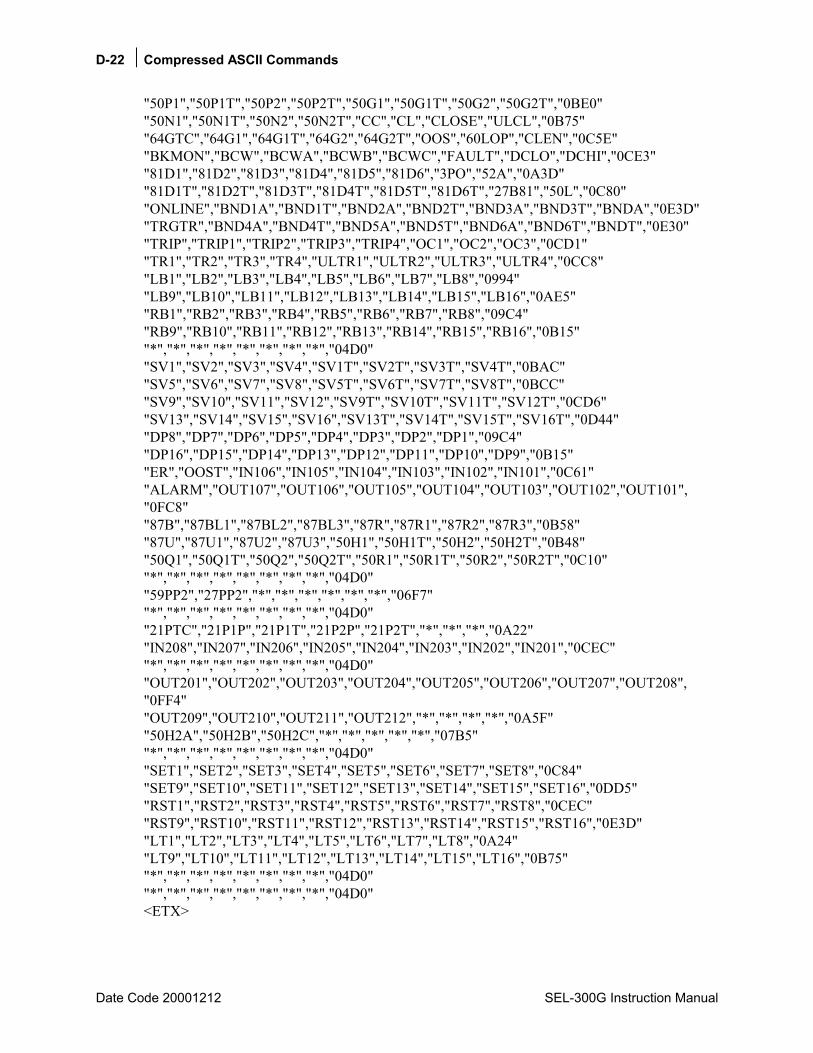
D-22 Compressed ASCII Commands
Date Code 20001212 SEL-300G Instruction Manual
"50P1","50P1T","50P2","50P2T","50G1","50G1T","50G2","50G2T","0BE0" "50N1","50N1T","50N2","50N2T","CC","CL","CLOSE","ULCL","0B75" "64GTC","64G1","64G1T","64G2","64G2T","OOS","60LOP","CLEN","0C5E" "BKMON","BCW","BCWA","BCWB","BCWC","FAULT","DCLO","DCHI","0CE3" "81D1","81D2","81D3","81D4","81D5","81D6","3PO","52A","0A3D" "81D1T","81D2T","81D3T","81D4T","81D5T","81D6T","27B81","50L","0C80" "ONLINE","BND1A","BND1T","BND2A","BND2T","BND3A","BND3T","BNDA","0E3D" "TRGTR","BND4A","BND4T","BND5A","BND5T","BND6A","BND6T","BNDT","0E30" "TRIP","TRIP1","TRIP2","TRIP3","TRIP4","OC1","OC2","OC3","0CD1" "TR1","TR2","TR3","TR4","ULTR1","ULTR2","ULTR3","ULTR4","0CC8" "LB1","LB2","LB3","LB4","LB5","LB6","LB7","LB8","0994" "LB9","LB10","LB11","LB12","LB13","LB14","LB15","LB16","0AE5" "RB1","RB2","RB3","RB4","RB5","RB6","RB7","RB8","09C4" "RB9","RB10","RB11","RB12","RB13","RB14","RB15","RB16","0B15" "*","*","*","*","*","*","*","*","04D0" "SV1","SV2","SV3","SV4","SV1T","SV2T","SV3T","SV4T","0BAC" "SV5","SV6","SV7","SV8","SV5T","SV6T","SV7T","SV8T","0BCC" "SV9","SV10","SV11","SV12","SV9T","SV10T","SV11T","SV12T","0CD6" "SV13","SV14","SV15","SV16","SV13T","SV14T","SV15T","SV16T","0D44" "DP8","DP7","DP6","DP5","DP4","DP3","DP2","DP1","09C4" "DP16","DP15","DP14","DP13","DP12","DP11","DP10","DP9","0B15" "ER","OOST","IN106","IN105","IN104","IN103","IN102","IN101","0C61" "ALARM","OUT107","OUT106","OUT105","OUT104","OUT103","OUT102","OUT101", "0FC8" "87B","87BL1","87BL2","87BL3","87R","87R1","87R2","87R3","0B58" "87U","87U1","87U2","87U3","50H1","50H1T","50H2","50H2T","0B48" "50Q1","50Q1T","50Q2","50Q2T","50R1","50R1T","50R2","50R2T","0C10" "*","*","*","*","*","*","*","*","04D0" "59PP2","27PP2","*","*","*","*","*","*","06F7" "*","*","*","*","*","*","*","*","04D0" "21PTC","21P1P","21P1T","21P2P","21P2T","*","*","*","0A22" "IN208","IN207","IN206","IN205","IN204","IN203","IN202","IN201","0CEC" "*","*","*","*","*","*","*","*","04D0" "OUT201","OUT202","OUT203","OUT204","OUT205","OUT206","OUT207","OUT208", "0FF4" "OUT209","OUT210","OUT211","OUT212","*","*","*","*","0A5F" "50H2A","50H2B","50H2C","*","*","*","*","*","07B5" "*","*","*","*","*","*","*","*","04D0" "SET1","SET2","SET3","SET4","SET5","SET6","SET7","SET8","0C84" "SET9","SET10","SET11","SET12","SET13","SET14","SET15","SET16","0DD5" "RST1","RST2","RST3","RST4","RST5","RST6","RST7","RST8","0CEC" "RST9","RST10","RST11","RST12","RST13","RST14","RST15","RST16","0E3D" "LT1","LT2","LT3","LT4","LT5","LT6","LT7","LT8","0A24" "LT9","LT10","LT11","LT12","LT13","LT14","LT15","LT16","0B75" "*","*","*","*","*","*","*","*","04D0" "*","*","*","*","*","*","*","*","04D0" <ETX>

Configuration, Fast Meter, and Fast Operate Commands D-23
SEL-300G Instruction Manual Date Code 20001212
Model SEL-0300G20 DNA message is: <STX>"EN","BKR","LOP","TRIP","21/51V","50","51","N","0983" "24","27/59","32","40","46","64G","81","87","07A8" "24TC","24D1","24D1T","24C2","24C2T","24CR","SS1","SS2","0B3B" "27P1","27P2","27PP1","27V1","59P1","59P2","59G1","59G2","0B2B" "32PTC","32P1","32P1T","32P2","32P2T","59V1","59Q","59PP1","0C01" "40ZTC","40Z1","40Z1T","40Z2","40Z2T","SWING","SG1","SG2","0C5A" "46QTC","46Q1","46Q1T","46Q2","46Q2T","46Q2R","INAD","INADT","0CF7" "78R1","78R2","78Z1","OOSTC","51CTC","51C","51CT","51CR","0BC8" "51GTC","51G","51GT","51GR","51NTC","51N","51NT","51NR","0B7E" "51VTC","51V","51VT","51VR","PDEM","QDEM","GDEM","NDEM","0C3B" "50P1","50P1T","50P2","50P2T","50G1","50G1T","50G2","50G2T","0BE0" "50N1","50N1T","50N2","50N2T","CC","CL","CLOSE","ULCL","0B75" "64GTC","64G1","64G1T","64G2","64G2T","OOS","60LOP","CLEN","0C5E" "BKMON","BCW","BCWA","BCWB","BCWC","FAULT","DCLO","DCHI","0CE3" "81D1","81D2","81D3","81D4","81D5","81D6","3PO","52A","0A3D" "81D1T","81D2T","81D3T","81D4T","81D5T","81D6T","27B81","50L","0C80" "ONLINE","BND1A","BND1T","BND2A","BND2T","BND3A","BND3T","BNDA","0E3D" "TRGTR","BND4A","BND4T","BND5A","BND5T","BND6A","BND6T","BNDT","0E30" "TRIP","TRIP1","TRIP2","TRIP3","TRIP4","OC1","OC2","OC3","0CD1" "TR1","TR2","TR3","TR4","ULTR1","ULTR2","ULTR3","ULTR4","0CC8" "LB1","LB2","LB3","LB4","LB5","LB6","LB7","LB8","0994" "LB9","LB10","LB11","LB12","LB13","LB14","LB15","LB16","0AE5" "RB1","RB2","RB3","RB4","RB5","RB6","RB7","RB8","09C4" "RB9","RB10","RB11","RB12","RB13","RB14","RB15","RB16","0B15" "*","*","*","*","*","*","*","*","04D0" "SV1","SV2","SV3","SV4","SV1T","SV2T","SV3T","SV4T","0BAC" "SV5","SV6","SV7","SV8","SV5T","SV6T","SV7T","SV8T","0BCC" "SV9","SV10","SV11","SV12","SV9T","SV10T","SV11T","SV12T","0CD6" "SV13","SV14","SV15","SV16","SV13T","SV14T","SV15T","SV16T","0D44" "DP8","DP7","DP6","DP5","DP4","DP3","DP2","DP1","09C4" "DP16","DP15","DP14","DP13","DP12","DP11","DP10","DP9","0B15" "ER","OOST","IN106","IN105","IN104","IN103","IN102","IN101","0C61" "ALARM","OUT107","OUT106","OUT105","OUT104","OUT103","OUT102","OUT101", "0FC8" "*","*","*","*","*","*","*","*","04D0" "*","*","*","*","*","*","*","*","04D0" "*","*","*","*","*","*","*","*","04D0" "59VP","59VS","CFA","BKRCF","BSYNCH","25C","25A1","25A2","0C01" "59PP2","27PP2","SF","VDIF","GENVHI","GENVLO","GENFHI","GENFLO","0EB5" "87NTC","87N1P","87N1T","87N2P","87N2T","*","*","27VS","0B3C" "21PTC","21P1P","21P1T","21P2P","21P2T","*","*","*","0A22" "*","*","*","*","*","*","*","*","04D0" "*","*","*","*","*","*","*","*","04D0" "*","*","*","*","*","*","*","*","04D0" "*","*","*","*","*","*","*","*","04D0" "*","*","*","*","*","*","*","*","04D0" "*","*","*","*","*","*","*","*","04D0"
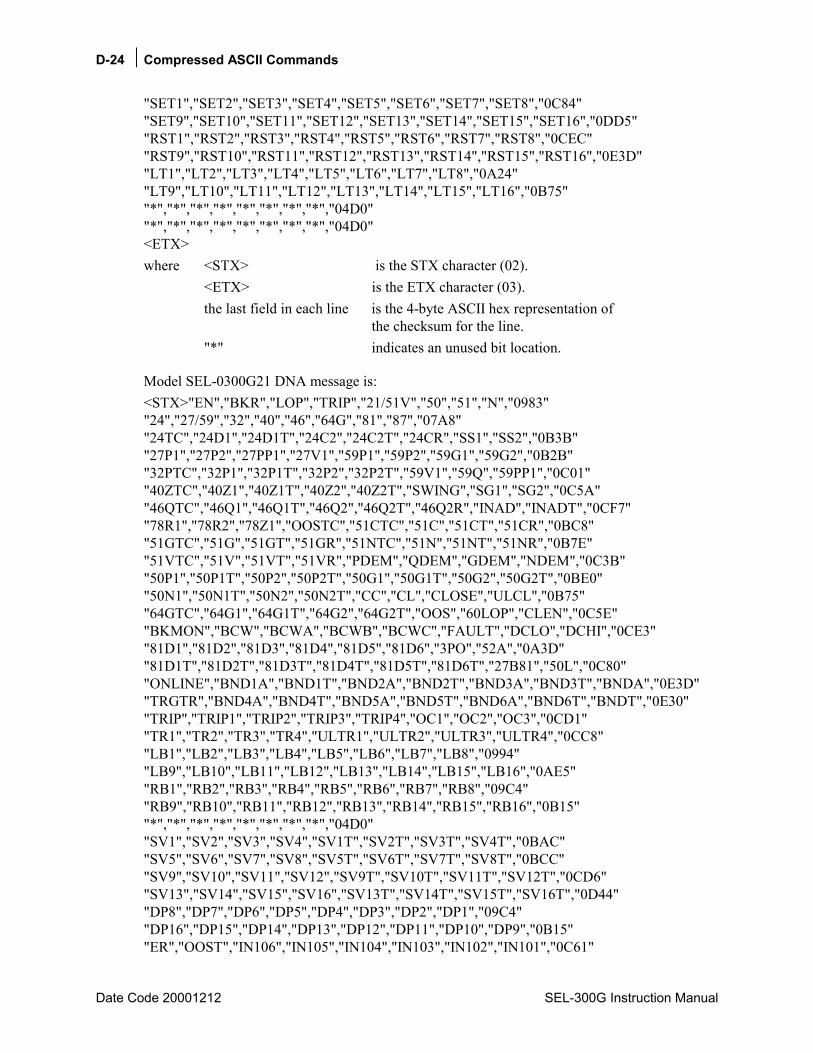
D-24 Compressed ASCII Commands
Date Code 20001212 SEL-300G Instruction Manual
"SET1","SET2","SET3","SET4","SET5","SET6","SET7","SET8","0C84" "SET9","SET10","SET11","SET12","SET13","SET14","SET15","SET16","0DD5" "RST1","RST2","RST3","RST4","RST5","RST6","RST7","RST8","0CEC" "RST9","RST10","RST11","RST12","RST13","RST14","RST15","RST16","0E3D" "LT1","LT2","LT3","LT4","LT5","LT6","LT7","LT8","0A24" "LT9","LT10","LT11","LT12","LT13","LT14","LT15","LT16","0B75" "*","*","*","*","*","*","*","*","04D0" "*","*","*","*","*","*","*","*","04D0" <ETX> where <STX> is the STX character (02). <ETX> is the ETX character (03). the last field in each line is the 4-byte ASCII hex representation of
the checksum for the line. "*" indicates an unused bit location.
Model SEL-0300G21 DNA message is: <STX>"EN","BKR","LOP","TRIP","21/51V","50","51","N","0983" "24","27/59","32","40","46","64G","81","87","07A8" "24TC","24D1","24D1T","24C2","24C2T","24CR","SS1","SS2","0B3B" "27P1","27P2","27PP1","27V1","59P1","59P2","59G1","59G2","0B2B" "32PTC","32P1","32P1T","32P2","32P2T","59V1","59Q","59PP1","0C01" "40ZTC","40Z1","40Z1T","40Z2","40Z2T","SWING","SG1","SG2","0C5A" "46QTC","46Q1","46Q1T","46Q2","46Q2T","46Q2R","INAD","INADT","0CF7" "78R1","78R2","78Z1","OOSTC","51CTC","51C","51CT","51CR","0BC8" "51GTC","51G","51GT","51GR","51NTC","51N","51NT","51NR","0B7E" "51VTC","51V","51VT","51VR","PDEM","QDEM","GDEM","NDEM","0C3B" "50P1","50P1T","50P2","50P2T","50G1","50G1T","50G2","50G2T","0BE0" "50N1","50N1T","50N2","50N2T","CC","CL","CLOSE","ULCL","0B75" "64GTC","64G1","64G1T","64G2","64G2T","OOS","60LOP","CLEN","0C5E" "BKMON","BCW","BCWA","BCWB","BCWC","FAULT","DCLO","DCHI","0CE3" "81D1","81D2","81D3","81D4","81D5","81D6","3PO","52A","0A3D" "81D1T","81D2T","81D3T","81D4T","81D5T","81D6T","27B81","50L","0C80" "ONLINE","BND1A","BND1T","BND2A","BND2T","BND3A","BND3T","BNDA","0E3D" "TRGTR","BND4A","BND4T","BND5A","BND5T","BND6A","BND6T","BNDT","0E30" "TRIP","TRIP1","TRIP2","TRIP3","TRIP4","OC1","OC2","OC3","0CD1" "TR1","TR2","TR3","TR4","ULTR1","ULTR2","ULTR3","ULTR4","0CC8" "LB1","LB2","LB3","LB4","LB5","LB6","LB7","LB8","0994" "LB9","LB10","LB11","LB12","LB13","LB14","LB15","LB16","0AE5" "RB1","RB2","RB3","RB4","RB5","RB6","RB7","RB8","09C4" "RB9","RB10","RB11","RB12","RB13","RB14","RB15","RB16","0B15" "*","*","*","*","*","*","*","*","04D0" "SV1","SV2","SV3","SV4","SV1T","SV2T","SV3T","SV4T","0BAC" "SV5","SV6","SV7","SV8","SV5T","SV6T","SV7T","SV8T","0BCC" "SV9","SV10","SV11","SV12","SV9T","SV10T","SV11T","SV12T","0CD6" "SV13","SV14","SV15","SV16","SV13T","SV14T","SV15T","SV16T","0D44" "DP8","DP7","DP6","DP5","DP4","DP3","DP2","DP1","09C4" "DP16","DP15","DP14","DP13","DP12","DP11","DP10","DP9","0B15" "ER","OOST","IN106","IN105","IN104","IN103","IN102","IN101","0C61"

Configuration, Fast Meter, and Fast Operate Commands D-25
SEL-300G Instruction Manual Date Code 20001212
"ALARM","OUT107","OUT106","OUT105","OUT104","OUT103","OUT102","OUT101", "0FC8" "*","*","*","*","*","*","*","*","04D0" "*","*","*","*","*","*","*","*","04D0" "*","*","*","*","*","*","*","*","04D0" "59VP","59VS","CFA","BKRCF","BSYNCH","25C","25A1","25A2","0C01" "59PP2","27PP2","SF","VDIF","GENVHI","GENVLO","GENFHI","GENFLO","0EB5" "87NTC","87N1P","87N1T","87N2P","87N2T","*","*","27VS","0B3C" "21PTC","21P1P","21P1T","21P2P","21P2T","*","*","*","0A22" "IN208","IN207","IN206","IN205","IN204","IN203","IN202","IN201","0CEC" "*","*","*","*","*","*","*","*","04D0" "OUT201","OUT202","OUT203","OUT204","OUT205","OUT206","OUT207","OUT208", "0FF4" "OUT209","OUT210","OUT211","OUT212","*","*","*","*","0A5F" "*","*","*","*","*","*","*","*","04D0" "*","*","*","*","*","*","*","*","04D0" "SET1","SET2","SET3","SET4","SET5","SET6","SET7","SET8","0C84" "SET9","SET10","SET11","SET12","SET13","SET14","SET15","SET16","0DD5" "RST1","RST2","RST3","RST4","RST5","RST6","RST7","RST8","0CEC" "RST9","RST10","RST11","RST12","RST13","RST14","RST15","RST16","0E3D" "LT1","LT2","LT3","LT4","LT5","LT6","LT7","LT8","0A24" "LT9","LT10","LT11","LT12","LT13","LT14","LT15","LT16","0B75" "*","*","*","*","*","*","*","*","04D0" "*","*","*","*","*","*","*","*","04D0" <ETX>
Model SEL-0300G30 DNA message is: <STX>"EN","BKR","LOP","TRIP","21/51V","50","51","N","0983" "24","27/59","32","40","46","64G","81","87","07A8" "24TC","24D1","24D1T","24C2","24C2T","24CR","SS1","SS2","0B3B" "27P1","27P2","27PP1","27V1","59P1","59P2","59G1","59G2","0B2B" "32PTC","32P1","32P1T","32P2","32P2T","59V1","59Q","59PP1","0C01" "40ZTC","40Z1","40Z1T","40Z2","40Z2T","SWING","SG1","SG2","0C5A" "46QTC","46Q1","46Q1T","46Q2","46Q2T","46Q2R","INAD","INADT","0CF7" "78R1","78R2","78Z1","OOSTC","51CTC","51C","51CT","51CR","0BC8" "51GTC","51G","51GT","51GR","51NTC","51N","51NT","51NR","0B7E" "51VTC","51V","51VT","51VR","PDEM","QDEM","GDEM","NDEM","0C3B" "50P1","50P1T","50P2","50P2T","50G1","50G1T","50G2","50G2T","0BE0" "50N1","50N1T","50N2","50N2T","CC","CL","CLOSE","ULCL","0B75" "64GTC","64G1","64G1T","64G2","64G2T","OOS","60LOP","CLEN","0C5E" "BKMON","BCW","BCWA","BCWB","BCWC","FAULT","DCLO","DCHI","0CE3" "81D1","81D2","81D3","81D4","81D5","81D6","3PO","52A","0A3D" "81D1T","81D2T","81D3T","81D4T","81D5T","81D6T","27B81","50L","0C80" "ONLINE","BND1A","BND1T","BND2A","BND2T","BND3A","BND3T","BNDA","0E3D" "TRGTR","BND4A","BND4T","BND5A","BND5T","BND6A","BND6T","BNDT","0E30" "TRIP","TRIP1","TRIP2","TRIP3","TRIP4","OC1","OC2","OC3","0CD1" "TR1","TR2","TR3","TR4","ULTR1","ULTR2","ULTR3","ULTR4","0CC8" "LB1","LB2","LB3","LB4","LB5","LB6","LB7","LB8","0994" "LB9","LB10","LB11","LB12","LB13","LB14","LB15","LB16","0AE5"

D-26 Compressed ASCII Commands
Date Code 20001212 SEL-300G Instruction Manual
"RB1","RB2","RB3","RB4","RB5","RB6","RB7","RB8","09C4" "RB9","RB10","RB11","RB12","RB13","RB14","RB15","RB16","0B15" "*","*","*","*","*","*","*","*","04D0" "SV1","SV2","SV3","SV4","SV1T","SV2T","SV3T","SV4T","0BAC" "SV5","SV6","SV7","SV8","SV5T","SV6T","SV7T","SV8T","0BCC" "SV9","SV10","SV11","SV12","SV9T","SV10T","SV11T","SV12T","0CD6" "SV13","SV14","SV15","SV16","SV13T","SV14T","SV15T","SV16T","0D44" "DP8","DP7","DP6","DP5","DP4","DP3","DP2","DP1","09C4" "DP16","DP15","DP14","DP13","DP12","DP11","DP10","DP9","0B15" "ER","OOST","IN106","IN105","IN104","IN103","IN102","IN101","0C61" "ALARM","OUT107","OUT106","OUT105","OUT104","OUT103","OUT102","OUT101", "0FC8" "87B","87BL1","87BL2","87BL3","87R","87R1","87R2","87R3","0B58" "87U","87U1","87U2","87U3","50H1","50H1T","50H2","50H2T","0B48" "50Q1","50Q1T","50Q2","50Q2T","50R1","50R1T","50R2","50R2T","0C10" "59VP","59VS","CFA","BKRCF","BSYNCH","25C","25A1","25A2","0C01" "59PP2","27PP2","SF","VDIF","GENVHI","GENVLO","GENFHI","GENFLO","0EB5" "*","*","*","*","*","*","*","27VS","05B8" "21PTC","21P1P","21P1T","21P2P","21P2T","*","*","*","0A22" "*","*","*","*","*","*","*","*","04D0" "*","*","*","*","*","*","*","*","04D0" "*","*","*","*","*","*","*","*","04D0" "*","*","*","*","*","*","*","*","04D0" "50H2A","50H2B","50H2C","*","*","*","*","*","07B5" "*","*","*","*","*","*","*","*","04D0" "SET1","SET2","SET3","SET4","SET5","SET6","SET7","SET8","0C84" "SET9","SET10","SET11","SET12","SET13","SET14","SET15","SET16","0DD5" "RST1","RST2","RST3","RST4","RST5","RST6","RST7","RST8","0CEC" "RST9","RST10","RST11","RST12","RST13","RST14","RST15","RST16","0E3D" "LT1","LT2","LT3","LT4","LT5","LT6","LT7","LT8","0A24" "LT9","LT10","LT11","LT12","LT13","LT14","LT15","LT16","0B75" "*","*","*","*","*","*","*","*","04D0" "*","*","*","*","*","*","*","*","04D0" <ETX>
Model SEL-0300G31 DNA message is: <STX>"EN","BKR","LOP","TRIP","21/51V","50","51","N","0983" "24","27/59","32","40","46","64G","81","87","07A8" "24TC","24D1","24D1T","24C2","24C2T","24CR","SS1","SS2","0B3B" "27P1","27P2","27PP1","27V1","59P1","59P2","59G1","59G2","0B2B" "32PTC","32P1","32P1T","32P2","32P2T","59V1","59Q","59PP1","0C01" "40ZTC","40Z1","40Z1T","40Z2","40Z2T","SWING","SG1","SG2","0C5A" "46QTC","46Q1","46Q1T","46Q2","46Q2T","46Q2R","INAD","INADT","0CF7" "78R1","78R2","78Z1","OOSTC","51CTC","51C","51CT","51CR","0BC8" "51GTC","51G","51GT","51GR","51NTC","51N","51NT","51NR","0B7E" "51VTC","51V","51VT","51VR","PDEM","QDEM","GDEM","NDEM","0C3B" "50P1","50P1T","50P2","50P2T","50G1","50G1T","50G2","50G2T","0BE0" "50N1","50N1T","50N2","50N2T","CC","CL","CLOSE","ULCL","0B75" "64GTC","64G1","64G1T","64G2","64G2T","OOS","60LOP","CLEN","0C5E"
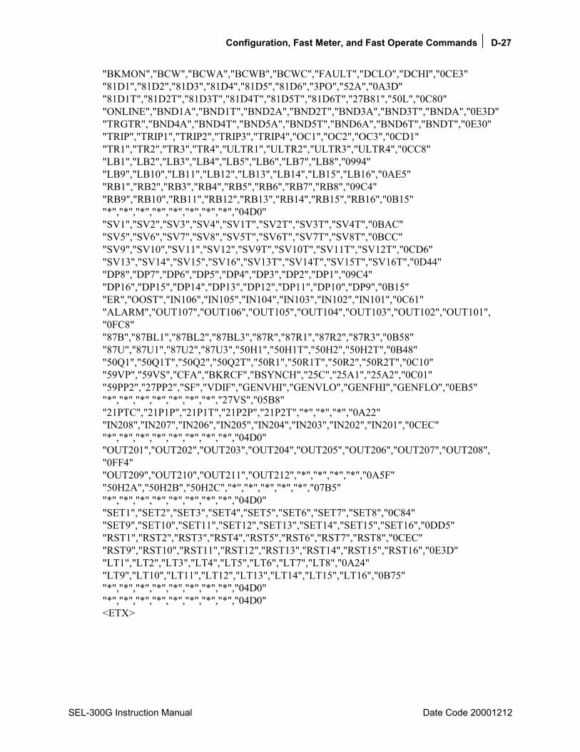
Configuration, Fast Meter, and Fast Operate Commands D-27
SEL-300G Instruction Manual Date Code 20001212
"BKMON","BCW","BCWA","BCWB","BCWC","FAULT","DCLO","DCHI","0CE3" "81D1","81D2","81D3","81D4","81D5","81D6","3PO","52A","0A3D" "81D1T","81D2T","81D3T","81D4T","81D5T","81D6T","27B81","50L","0C80" "ONLINE","BND1A","BND1T","BND2A","BND2T","BND3A","BND3T","BNDA","0E3D" "TRGTR","BND4A","BND4T","BND5A","BND5T","BND6A","BND6T","BNDT","0E30" "TRIP","TRIP1","TRIP2","TRIP3","TRIP4","OC1","OC2","OC3","0CD1" "TR1","TR2","TR3","TR4","ULTR1","ULTR2","ULTR3","ULTR4","0CC8" "LB1","LB2","LB3","LB4","LB5","LB6","LB7","LB8","0994" "LB9","LB10","LB11","LB12","LB13","LB14","LB15","LB16","0AE5" "RB1","RB2","RB3","RB4","RB5","RB6","RB7","RB8","09C4" "RB9","RB10","RB11","RB12","RB13","RB14","RB15","RB16","0B15" "*","*","*","*","*","*","*","*","04D0" "SV1","SV2","SV3","SV4","SV1T","SV2T","SV3T","SV4T","0BAC" "SV5","SV6","SV7","SV8","SV5T","SV6T","SV7T","SV8T","0BCC" "SV9","SV10","SV11","SV12","SV9T","SV10T","SV11T","SV12T","0CD6" "SV13","SV14","SV15","SV16","SV13T","SV14T","SV15T","SV16T","0D44" "DP8","DP7","DP6","DP5","DP4","DP3","DP2","DP1","09C4" "DP16","DP15","DP14","DP13","DP12","DP11","DP10","DP9","0B15" "ER","OOST","IN106","IN105","IN104","IN103","IN102","IN101","0C61" "ALARM","OUT107","OUT106","OUT105","OUT104","OUT103","OUT102","OUT101", "0FC8" "87B","87BL1","87BL2","87BL3","87R","87R1","87R2","87R3","0B58" "87U","87U1","87U2","87U3","50H1","50H1T","50H2","50H2T","0B48" "50Q1","50Q1T","50Q2","50Q2T","50R1","50R1T","50R2","50R2T","0C10" "59VP","59VS","CFA","BKRCF","BSYNCH","25C","25A1","25A2","0C01" "59PP2","27PP2","SF","VDIF","GENVHI","GENVLO","GENFHI","GENFLO","0EB5" "*","*","*","*","*","*","*","27VS","05B8" "21PTC","21P1P","21P1T","21P2P","21P2T","*","*","*","0A22" "IN208","IN207","IN206","IN205","IN204","IN203","IN202","IN201","0CEC" "*","*","*","*","*","*","*","*","04D0" "OUT201","OUT202","OUT203","OUT204","OUT205","OUT206","OUT207","OUT208", "0FF4" "OUT209","OUT210","OUT211","OUT212","*","*","*","*","0A5F" "50H2A","50H2B","50H2C","*","*","*","*","*","07B5" "*","*","*","*","*","*","*","*","04D0" "SET1","SET2","SET3","SET4","SET5","SET6","SET7","SET8","0C84" "SET9","SET10","SET11","SET12","SET13","SET14","SET15","SET16","0DD5" "RST1","RST2","RST3","RST4","RST5","RST6","RST7","RST8","0CEC" "RST9","RST10","RST11","RST12","RST13","RST14","RST15","RST16","0E3D" "LT1","LT2","LT3","LT4","LT5","LT6","LT7","LT8","0A24" "LT9","LT10","LT11","LT12","LT13","LT14","LT15","LT16","0B75" "*","*","*","*","*","*","*","*","04D0" "*","*","*","*","*","*","*","*","04D0" <ETX>
D-28 Compressed ASCII Commands
Date Code 20001212 SEL-300G Instruction Manual
BNA Message In response to the BNA command, the relay sends names of the bits transmitted in the Status Byte in the A5D1 message. The first name is the MSB; the last name is the LSB. The BNA message is:
<STX>"*","*","*","STSET","*","*","*","*","yyyy"<ETX>
where: "yyyy" is the 4-byte ASCII representation of the checksum.
"*" indicates an unused bit location.
The BNA command is available from Access Level 1 and higher.

Compressed ASCII Commands E-1
SEL-300G Instruction Manual Date Code 20001212
APPENDIX E: COMPRESSED ASCII COMMANDS
INTRODUCTION The SEL-300G Relay provides compressed ASCII versions of some of the relays ASCII commands. The compressed ASCII commands allow an external device to obtain data from the relay in a format which directly imports into spreadsheet or database programs and that can be validated with a checksum.
The SEL-300G Relay provides the following compressed ASCII commands:
Command Description CASCII Configuration message CSTATUS Status message CHISTORY History message CEVENT Event message
CASCII COMMAND GENERAL FORMAT The compressed ASCII configuration message provides data for an external computer to extract data from other compressed ASCII commands. To obtain the configuration message for the compressed ASCII commands available in an SEL relay, type:
CAS <CR>
The relay sends: <STX>"CAS",n,"yyyy"<CR> "COMMAND 1",ll,"yyyy"<CR> "#H","xxxxx","xxxxx",......,"xxxxx","yyyy"<CR> "#D","ddd","ddd","ddd","ddd",......,"ddd","yyyy"<CR> "COMMAND 2",ll,"yyyy"<CR> "#h","ddd","ddd",......,"ddd","yyyy"<CR> "#D","ddd","ddd","ddd","ddd",......,"ddd","yyyy"<CR>
"COMMAND n",ll,"yyyy"<CR> "#H","xxxxx","xxxxx",......,"xxxxx","yyyy"<CR> "#D","ddd","ddd","ddd","ddd",......,"ddd","yyyy"<CR><ETX>
where: n is the number of compressed ASCII command descriptions to follow. COMMAND is the ASCII name for the compressed ASCII command as sent by the
requesting device. The naming convention for the compressed ASCII commands is a 'C' preceding the typical command. For example, CSTATUS (abbreviated to CST) is the compressed STATUS command.
ll is the minimum access level at which the command is available. #H identifies a header line to precede one or more data lines; '#' is the

E-2 Compressed ASCII Commands
Date Code 20001212 SEL-300G Instruction Manual
number of subsequent ASCII names. For example, 21H identifies a header line with 21 ASCII labels.
#h identifies a header line to precede one or more data lines; '#' is the number of subsequent format fields. For example, 8h identifies a header line with 8 format fields.
xxxxx is an ASCII name for corresponding data on following data lines. Maximum ASCII name width is 10 characters.
#D identifies a data format line; '#' is the maximum number of subsequent data lines.
ddd identifies a format field containing one of the following type designators: I Integer data F Floating point data mS String of maximum m characters (e.g., 10S for a 10 character string)
yyyy is the 4-byte hex ASCII representation of the checksum.
A compressed ASCII command may require multiple header and data configuration lines.
If a compressed ASCII request is made for data that are not available (e.g. the history buffer is empty or invalid event request), the relay responds with the following message:
<STX>"No Data Available","0668"<CR><ETX>
CASCII COMMAND SEL-300G Display the SEL-300G Relay compressed ASCII configuration message by sending:
CAS <CR>
Model SEL-0300G0 Relay sends: <STX> "CAS",5,"yyyy"<CR> "CST",1,"yyyy"<CR> "1H","FID","yyyy"<CR> "1D","46S","yyyy"<CR> "7H","MONTH","DAY","YEAR","HOUR","MIN","SEC","MSEC","yyyy"<CR> "1D","I","I","I","I","I","I","I","yyyy",<CR> "27H","IA","IB","IC","IN","VA","VB","VC","VN","MOF","*","*","*","*","+5V_PS", "+5V_REG", "-5V_REG","+12V_PS","-12V_PS","+15V_PS","-15V_PS","TEMP","RAM","ROM", "A/D","CR_RAM","EEPROM","IO_BRD","yyyy"<CR> "1D","9S","9S","9S","9S","9S","9S","9S","9S","9S","9S","9S","9S","9S","9S","9S","9S","9S", "9S","9S","9S","9S","9S","9S","yyyy"<CR> "CHI",1,"yyyy"<CR> "1H","FID","yyyy"<CR> "1D","46S","yyyy"<CR> "13H","REC_NUM","MONTH","DAY","YEAR","HOUR","MIN","SEC","MSEC","EVENT", "CURR","FREQ","GROUP","TARGETS","yyyy"<CR>
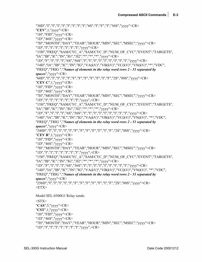
Compressed ASCII Commands E-3
SEL-300G Instruction Manual Date Code 20001212
"30D","I","I","I","I","I","I","I","I","6S","I","F","I","56S","yyyy"<CR> "CEV",1,"yyyy"<CR> "1H","FID","yyyy"<CR> "1D","46S","yyyy"<CR> "7H","MONTH","DAY","YEAR","HOUR","MIN","SEC","MSEC","yyyy"<CR> "1D","I","I","I","I","I","I","I","yyyy"<CR> "15H","FREQ","SAM/CYC_A","SAM/CYC_D","NUM_OF_CYC","EVENT","TARGETS", "IA","IB","IC","IN","IG","3I2","*","*","*","yyyy"<CR> "1D","F","I","I","I","6S","56S","I","I","I","I","I","I","I","I","I","yyyy"<CR> "14H","IA","IB","IC","IN","IG","VA(kV)","VB(kV)","VC(kV)","VN(kV)","*","VDC", "FREQ","TRIG ","Names of elements in the relay word rows 2 - 51 separated by spaces","yyyy"<CR> "60D","I","I","I","I","I","F","F","F","F","F","I","F","2S","88S","yyyy"<CR> "CEV C",1,"yyyy"<CR> "1H","FID","yyyy"<CR> "1D","46S","yyyy"<CR> "7H","MONTH","DAY","YEAR","HOUR","MIN","SEC","MSEC","yyyy"<CR> "1D","I","I","I","I","I","I","I","yyyy",<CR> "15H","FREQ","SAM/CYC_A","SAM/CYC_D","NUM_OF_CYC","EVENT","TARGETS", "IA","IB","IC","IN","IG","3I2","*","*","*","yyyy"<CR> "1D","F","I","I","I","6S","56S","I","I","I","I","I","I","I","I","I","yyyy"<CR> "14H","IA","IB","IC","IN","IG","VA(kV)","VB(kV)","VC(kV)","VN(kV)", "*","VDC", "FREQ","TRIG ","Names of elements in the relay word rows 2 - 51 separated by spaces","yyyy"<CR> "240D","I","I","I","I","I","F","F","F","F","F","I","F","2S","88S","yyyy"<CR> "CEV R",1,"yyyy"<CR> "1H","FID","yyyy"<CR> "1D","46S","yyyy"<CR> "7H","MONTH","DAY","YEAR","HOUR","MIN","SEC","MSEC","yyyy"<CR> "1D","I","I","I","I","I","I","I","yyyy",<CR> "15H","FREQ","SAM/CYC_A","SAM/CYC_D","NUM_OF_CYC","EVENT","TARGETS", "IA","IB","IC","IN","IG","3I2","*","*","*","yyyy"<CR> "1D","F","I","I","I","6S","56S","I","I","I","I","I","I","I","I","I","yyyy"<CR> "14H","IA","IB","IC","IN","IG","VA(kV)","VB(kV)","VC(kV)","VN(kV)", "*","VDC", "FREQ","TRIG ","Names of elements in the relay word rows 2 - 51 separated by spaces","yyyy"<CR> "256D","I","I","I","I","I","F","F","F","F","F","I","F","2S","88S","yyyy"<CR> <ETX>
Model SEL-0300G1 Relay sends: <STX> "CAS",5,"yyyy"<CR> "CST",1,"yyyy"<CR> "1H","FID","yyyy"<CR> "1D","46S","yyyy"<CR> "7H","MONTH","DAY","YEAR","HOUR","MIN","SEC","MSEC","yyyy"<CR> "1D","I","I","I","I","I","I","I","yyyy",<CR>
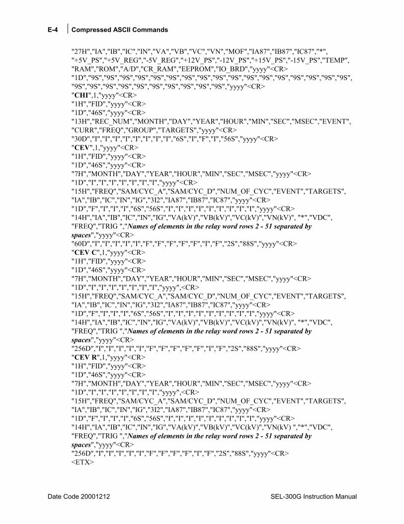
E-4 Compressed ASCII Commands
Date Code 20001212 SEL-300G Instruction Manual
"27H","IA","IB","IC","IN","VA","VB","VC","VN","MOF","IA87","IB87","IC87","*", "+5V_PS","+5V_REG","-5V_REG","+12V_PS","-12V_PS","+15V_PS","-15V_PS","TEMP", "RAM","ROM","A/D","CR_RAM","EEPROM","IO_BRD","yyyy"<CR> "1D","9S","9S","9S","9S","9S","9S","9S","9S","9S","9S","9S","9S","9S","9S","9S","9S","9S", "9S","9S","9S","9S","9S","9S","9S","9S","9S","9S","yyyy"<CR> "CHI",1,"yyyy"<CR> "1H","FID","yyyy"<CR> "1D","46S","yyyy"<CR> "13H","REC_NUM","MONTH","DAY","YEAR","HOUR","MIN","SEC","MSEC","EVENT", "CURR","FREQ","GROUP","TARGETS","yyyy"<CR> "30D","I","I","I","I","I","I","I","I","6S","I","F","I","56S","yyyy"<CR> "CEV",1,"yyyy"<CR> "1H","FID","yyyy"<CR> "1D","46S","yyyy"<CR> "7H","MONTH","DAY","YEAR","HOUR","MIN","SEC","MSEC","yyyy"<CR> "1D","I","I","I","I","I","I","I","yyyy"<CR> "15H","FREQ","SAM/CYC_A","SAM/CYC_D","NUM_OF_CYC","EVENT","TARGETS", "IA","IB","IC","IN","IG","3I2","IA87","IB87","IC87","yyyy"<CR> "1D","F","I","I","I","6S","56S","I","I","I","I","I","I","I","I","I","yyyy"<CR> "14H","IA","IB","IC","IN","IG","VA(kV)","VB(kV)","VC(kV)","VN(kV)", "*","VDC", "FREQ","TRIG ","Names of elements in the relay word rows 2 - 51 separated by spaces","yyyy"<CR> "60D","I","I","I","I","I","F","F","F","F","F","I","F","2S","88S","yyyy"<CR> "CEV C",1,"yyyy"<CR> "1H","FID","yyyy"<CR> "1D","46S","yyyy"<CR> "7H","MONTH","DAY","YEAR","HOUR","MIN","SEC","MSEC","yyyy"<CR> "1D","I","I","I","I","I","I","I","yyyy",<CR> "15H","FREQ","SAM/CYC_A","SAM/CYC_D","NUM_OF_CYC","EVENT","TARGETS", "IA","IB","IC","IN","IG","3I2","IA87","IB87","IC87","yyyy"<CR> "1D","F","I","I","I","6S","56S","I","I","I","I","I","I","I","I","I","yyyy"<CR> "14H","IA","IB","IC","IN","IG","VA(kV)","VB(kV)","VC(kV)","VN(kV)", "*","VDC", "FREQ","TRIG ","Names of elements in the relay word rows 2 - 51 separated by spaces","yyyy"<CR> "256D","I","I","I","I","I","F","F","F","F","F","I","F","2S","88S","yyyy"<CR> "CEV R",1,"yyyy"<CR> "1H","FID","yyyy"<CR> "1D","46S","yyyy"<CR> "7H","MONTH","DAY","YEAR","HOUR","MIN","SEC","MSEC","yyyy"<CR> "1D","I","I","I","I","I","I","I","yyyy",<CR> "15H","FREQ","SAM/CYC_A","SAM/CYC_D","NUM_OF_CYC","EVENT","TARGETS", "IA","IB","IC","IN","IG","3I2","IA87","IB87","IC87","yyyy"<CR> "1D","F","I","I","I","6S","56S","I","I","I","I","I","I","I","I","I","yyyy"<CR> "14H","IA","IB","IC","IN","IG","VA(kV)","VB(kV)","VC(kV)","VN(kV) ","*","VDC", "FREQ","TRIG ","Names of elements in the relay word rows 2 - 51 separated by spaces","yyyy"<CR> "256D","I","I","I","I","I","F","F","F","F","I","F","2S","88S","yyyy"<CR> <ETX>

Compressed ASCII Commands E-5
SEL-300G Instruction Manual Date Code 20001212
Model SEL-0300G2 Relay sends: <STX> "CAS",5,"yyyy"<CR> "CST",1,"yyyy"<CR> "1H","FID","yyyy"<CR> "1D","46S","yyyy"<CR> "7H","MONTH","DAY","YEAR","HOUR","MIN","SEC","MSEC","yyyy"<CR> "1D","I","I","I","I","I","I","I","yyyy",<CR> "27H","IA","IB","IC","IN","VA","VB","VC","VN","MOF","*","*","*","VS","+5V_PS", "+5V_REG","-5V_REG","+12V_PS","-12V_PS","+15V_PS","-15V_PS","TEMP","RAM","ROM","A/D","CR_RAM","EEPROM","IO_BRD","yyyy"<CR> "1D","9S","9S","9S","9S","9S","9S","9S","9S","9S","9S","9S","9S","9S","9S","9S","9S","9S", "9S","9S","9S","9S","9S","9S","yyyy"<CR> "CHI",1,"yyyy"<CR> "1H","FID","yyyy"<CR> "1D","46S","yyyy"<CR> "13H","REC_NUM","MONTH","DAY","YEAR","HOUR","MIN","SEC","MSEC","EVENT", "CURR","FREQ","GROUP","TARGETS","yyyy"<CR> "30D","I","I","I","I","I","I","I","I","6S","I","F","I","56S","yyyy"<CR> "CEV",1,"yyyy"<CR> "1H","FID","yyyy"<CR> "1D","46S","yyyy"<CR> "7H","MONTH","DAY","YEAR","HOUR","MIN","SEC","MSEC","yyyy"<CR> "1D","I","I","I","I","I","I","I","yyyy"<CR> "15H","FREQ","SAM/CYC_A","SAM/CYC_D","NUM_OF_CYC","EVENT","TARGETS", "IA","IB","IC","IN","IG","3I2","*","*","*","yyyy"<CR> "1D","F","I","I","I","6S","56S","I","I","I","I","I","I","I","I","I","yyyy"<CR> "14H","IA","IB","IC","IN","IG","VA(kV)","VB(kV)","VC(kV)","VN(kV)", "VS(kV) ","VDC", "FREQ","TRIG ","Names of elements in the relay word rows 2 - 51 separated by spaces","yyyy"<CR> "60D","I","I","I","I","I","F","F","F","F","F","I","F","2S","88S","yyyy"<CR> "CEV C",1,"yyyy"<CR> "1H","FID","yyyy"<CR> "1D","46S","yyyy"<CR> "7H","MONTH","DAY","YEAR","HOUR","MIN","SEC","MSEC","yyyy"<CR> "1D","I","I","I","I","I","I","I","yyyy",<CR> "15H","FREQ","SAM/CYC_A","SAM/CYC_D","NUM_OF_CYC","EVENT","TARGETS", "IA","IB","IC","IN","IG","3I2","*","*","*","yyyy"<CR> "1D","F","I","I","I","6S","56S","I","I","I","I","I","I","I","I","I","yyyy"<CR> "14H","IA","IB","IC","IN","IG","VA(kV)","VB(kV)","VC(kV)","VN(kV)", "VS(kV) ","VDC", "FREQ","TRIG ","Names of elements in the relay word rows 2 - 51 separated by spaces","yyyy"<CR> "240D","I","I","I","I","I","F","F","F","F","F","I","F","2S","88S","yyyy"<CR> "CEV R",1,"yyyy"<CR> "1H","FID","yyyy"<CR> "1D","46S","yyyy"<CR> "7H","MONTH","DAY","YEAR","HOUR","MIN","SEC","MSEC","yyyy"<CR> "1D","I","I","I","I","I","I","I","yyyy",<CR>

E-6 Compressed ASCII Commands
Date Code 20001212 SEL-300G Instruction Manual
"15H","FREQ","SAM/CYC_A","SAM/CYC_D","NUM_OF_CYC","EVENT","TARGETS", "IA","IB","IC","IN","IG","3I2","*","*","*","yyyy"<CR> "1D","F","I","I","I","6S","56S","I","I","I","I","I","I","I","I","I","yyyy"<CR> "14H","IA","IB","IC","IN","IG","VA(kV)","VB(kV)","VC(kV)","VN(kV)", "*","VDC", "FREQ","TRIG ","Names of elements in the relay word rows 2 - 51 separated by spaces","yyyy"<CR> "256D","I","I","I","I","I","F","F","F","F","F","I","F","2S","88S","yyyy"<CR> <ETX>
Model SEL-0300G3 Relay sends: <STX> "CAS",5,"yyyy"<CR> "CST",1,"yyyy"<CR> "1H","FID","yyyy"<CR> "1D","46S","yyyy"<CR> "7H","MONTH","DAY","YEAR","HOUR","MIN","SEC","MSEC","yyyy"<CR> "1D","I","I","I","I","I","I","I","yyyy",<CR> "27H","IA","IB","IC","IN","VA","VB","VC","VN","MOF","IA87","IB87","IC87","VS", "+5V_PS","+5V_REG","-5V_REG","+12V_PS","-12V_PS","+15V_PS","-15V_PS","TEMP","RAM","ROM","A/D","CR_RAM","EEPROM","IO_BRD","yyyy"<CR> "1D","9S","9S","9S","9S","9S","9S","9S","9S","9S","9S","9S","9S","9S","9S","9S","9S","9S", "9S","9S","9S","9S","9S","9S","9S","9S","9S","9S","yyyy"<CR> "CHI",1,"yyyy"<CR> "1H","FID","yyyy"<CR> "1D","46S","yyyy"<CR> "13H","REC_NUM","MONTH","DAY","YEAR","HOUR","MIN","SEC","MSEC","EVENT", "CURR","FREQ","GROUP","TARGETS","yyyy"<CR> "30D","I","I","I","I","I","I","I","I","6S","I","F","I","56S","yyyy"<CR> "CEV",1,"yyyy"<CR> "1H","FID","yyyy"<CR> "1D","46S","yyyy"<CR> "7H","MONTH","DAY","YEAR","HOUR","MIN","SEC","MSEC","yyyy"<CR> "1D","I","I","I","I","I","I","I","yyyy"<CR> "15H","FREQ","SAM/CYC_A","SAM/CYC_D","NUM_OF_CYC","EVENT","TARGETS", "IA","IB","IC","IN","IG","3I2","IA87","IB87","IC87","yyyy"<CR> "1D","F","I","I","I","6S","56S","I","I","I","I","I","I","I","I","I","yyyy"<CR> "14H","IA","IB","IC","IN","IG","VA(kV)","VB(kV)","VC(kV)","VN(kV)", "VS(kV) ","VDC", "FREQ","TRIG ","Names of elements in the relay word rows 2 - 51 separated by spaces","yyyy"<CR> "60D","I","I","I","I","I","F","F","F","F","F","I","F","2S","88S","yyyy"<CR> "CEV C",1,"yyyy"<CR> "1H","FID","yyyy"<CR> "1D","46S","yyyy"<CR> "7H","MONTH","DAY","YEAR","HOUR","MIN","SEC","MSEC","yyyy"<CR> "1D","I","I","I","I","I","I","I","yyyy",<CR> "15H","FREQ","SAM/CYC_A","SAM/CYC_D","NUM_OF_CYC","EVENT","TARGETS", "IA","IB","IC","IN","IG","3I2","IA87","IB87","IC87","yyyy"<CR> "1D","F","I","I","I","6S","56S","I","I","I","I","I","I","I","I","I","yyyy"<CR>

Compressed ASCII Commands E-7
SEL-300G Instruction Manual Date Code 20001212
"14H","IA","IB","IC","IN","IG","VA(kV)","VB(kV)","VC(kV)","VN(kV)", "VS(kV) ","VDC", "FREQ","TRIG ","Names of elements in the relay word rows 2 - 51 separated by spaces","yyyy"<CR> "256D","I","I","I","I","I","F","F","F","F","F","I","F","2S","88S","yyyy"<CR> "CEV R",1,"yyyy"<CR> "1H","FID","yyyy"<CR> "1D","46S","yyyy"<CR> "7H","MONTH","DAY","YEAR","HOUR","MIN","SEC","MSEC","yyyy"<CR> "1D","I","I","I","I","I","I","I","yyyy",<CR> "15H","FREQ","SAM/CYC_A","SAM/CYC_D","NUM_OF_CYC","EVENT","TARGETS", "IA","IB","IC","IN","IG","3I2","IA87","IB87","IC87","yyyy"<CR> "1D","F","I","I","I","6S","56S","I","I","I","I","I","I","I","I","I","yyyy"<CR> "14H","IA","IB","IC","IN","IG","VA(kV)","VB(kV)","VC(kV)","VN(kV)", "VS(kV) ","VDC", "FREQ","TRIG ","Names of elements in the relay word rows 2 - 51 separated by spaces","yyyy"<CR> "256D","I","I","I","I","I","F","F","F","F","I","F","2S","88S","yyyy"<CR> <ETX>
See the CEVENT command for definition of the Names of elements in the Relay Word Rows 2 - 51 separated by spaces field.
CSTATUS COMMAND SEL-300G
Display status data in compressed ASCII format by sending:
CST <CR>
Model SEL-0300G0 Relay sends: <STX>"FID","yyyy"<CR> "Relay FID string","yyyy"<CR> "MONTH","DAY","YEAR","HOUR","MIN","SEC","MSEC","yyyy"<CR> xxxx,xxxx,xxxx,xxxx,xxxx,xxxx,xxxx,"yyyy"<CR> "IA","IB","IC","IN","VA","VB","VC","VN","MOF","*","*","*","*","+5V_PS","+5V_REG", "-5V_REG","+12V_PS","-12V_PS","+15V_PS","-15V_PS","TEMP","RAM","ROM","A/D","CR_RAM","EEPROM","IO_BRD","yyyy"<CR> ,"xxxx","xxxx","xxxx","xxxx","xxxx","xxxx","xxxx", "xxxx","xxxx","xxxx","xxxx","xxxx","xxxx","xxxx","xxxx","xxxx","xxxx", "xxxx","xxxx","xxxx","xxxx","xxxx","xxxx","yyyy"<CR><ETX>

E-8 Compressed ASCII Commands
Date Code 20001212 SEL-300G Instruction Manual
Model SEL-0300G1 Relay sends: <STX>"FID","yyyy"<CR> "Relay FID string","yyyy"<CR> "MONTH","DAY","YEAR","HOUR","MIN","SEC","MSEC","yyyy"<CR> xxxx,xxxx,xxxx,xxxx,xxxx,xxxx,xxxx,"yyyy"<CR> "IA","IB","IC","IN","VA","VB","VC","VN","MOF","IA87","IB87","IC87","*","+5V_PS", "+5V_REG","-5V_REG","+12V_PS","-12V_PS","+15V_PS","-15V_PS","TEMP","RAM","ROM","A/D","CR_RAM","EEPROM","IO_BRD","yyyy"<CR> ,"xxxx","xxxx","xxxx","xxxx","xxxx","xxxx","xxxx", "xxxx","xxxx","xxxx","xxxx","xxxx","xxxx","xxxx","xxxx","xxxx","xxxx", "xxxx","xxxx","xxxx","xxxx","xxxx","xxxx","xxxx","xxxx","xxxx","yyyy"<CR><ETX>
Model SEL-0300G2 Relay sends: <STX>"FID","yyyy"<CR> "Relay FID string","yyyy"<CR> "MONTH","DAY","YEAR","HOUR","MIN","SEC","MSEC","yyyy"<CR> xxxx,xxxx,xxxx,xxxx,xxxx,xxxx,xxxx,"yyyy"<CR> "IA","IB","IC","IN","VA","VB","VC","VN","MOF","*","*","*","VS","+5V_PS", "+5V_REG","-5V_REG","+12V_PS","-12V_PS","+15V_PS","-15V_PS", "TEMP","RAM","ROM","A/D","CR_RAM","EEPROM","IO_BRD","yyyy"<CR> ,"xxxx","xxxx","xxxx","xxxx","xxxx","xxxx","xxxx", "xxxx","xxxx","xxxx","xxxx","xxxx","xxxx","xxxx","xxxx","xxxx","xxxx", "xxxx","xxxx","xxxx","xxxx","xxxx","xxxx","xxxx","yyyy"<CR><ETX>
Model SEL-0300G3 Relay sends: <STX>"FID","yyyy"<CR> "Relay FID string","yyyy"<CR> "MONTH","DAY","YEAR","HOUR","MIN","SEC","MSEC","yyyy"<CR> xxxx,xxxx,xxxx,xxxx,xxxx,xxxx,xxxx,"yyyy"<CR> "IA","IB","IC","IN","VA","VB","VC","VN","MOF","IA87","IB87","IC87","VS","+5V_PS", "+5V_REG","-5V_REG","+12V_PS","-12V_PS","+15V_PS","-15V_PS","TEMP","RAM","ROM","A/D","CR_RAM","EEPROM","IO_BRD","yyyy"<CR> ,"xxxx","xxxx","xxxx","xxxx","xxxx","xxxx","xxxx", "xxxx","xxxx","xxxx","xxxx","xxxx","xxxx","xxxx","xxxx","xxxx","xxxx", "xxxx","xxxx","xxxx","xxxx","xxxx","xxxx","xxxx","xxxx","xxxx","xxxx", "yyyy"<CR><ETX>
where: xxxx are the data values corresponding to the first line labels and yyyy is the 4-byte hex ASCII representation of the checksum.
Compressed ASCII Commands E-9
SEL-300G Instruction Manual Date Code 20001212
CHISTORY COMMAND SEL-300G
Display history data in compressed ASCII format by sending:
CHI <CR>
The relay sends: <STX>"FID","yyyy"<CR> "Relay FID string","yyyy"<CR> "REC_NUM","MONTH","DAY","YEAR","HOUR","MIN","SEC","MSEC","EVENT", "CURR","FREQ","GROUP","TARGETS","yyyy"<CR> xxxx,xxxx,xxxx,xxxx,xxxx,xxxx,xxxx,xxxx,"xxxx",xxxx,xxxx,xxxx,xxxx, "yyyy"<CR><ETX>
(the second line is then repeated for each record)
where: xxxx are the data values corresponding to the first line labels and yyyy is the 4-byte hex ASCII representation of the checksum.
If the history buffer is empty, the relay responds: <STX>"No Data Available","0668"<CR><ETX>
CEVENT COMMAND SEL-300G Display event report in compressed ASCII format by sending:
CEV [n Sx sec Ly[-[w]] R C DIF] (parameters in [ ] are optional)
where: n event number (1 - 29) if LER = 15, (1 - 15) if LER = 30, defaults to 1 Sx x samples per cycle (4 or 16); defaults to 4 Ly y cycles event report length (1 - LER) for filtered event reports, (1 - LER+1) for raw event reports, defaults to LER if not specified Ly- displays report from cycle y to LER Ly-w displays report from cycle y to cycle w R specifies raw (unfiltered) data; defaults to 16 samples per cycle unless overridden by the Sx parameter. Defaults to 16 cycles in length unless overridden with the Ly parameter. C specifies 16 samples per cycle, 15 cycle length. DIF Specifies differential data report (SEL-0300G1 and SEL-0300G3 models).
E-10 Compressed ASCII Commands
Date Code 20001212 SEL-300G Instruction Manual
The relay responds to the CEV command with the nth event report as shown below. Items in italics will be replaced with the actual relay data.
<STX>"FID","yyyy"<CR> "Relay FID string","yyyy"<CR> "MONTH","DAY","YEAR","HOUR","MIN","SEC","MSEC","yyyy"<CR> xxxx,xxxx,xxxx,xxxx,xxxx,xxxx,xxxx,"yyyy"<CR> "FREQ","SAM/CYC_A","SAM/CYC_D","NUM_OF_CYC","EVENT","TARGETS","IA","IB","IC","IN","IG","3I2","*","*","*","yyyy"<CR> xxxx,xxxx,xxxx,xxxx,"xxxx",xxxx,xxxx,xxxx,xxxx,xxxx,xxxx,xxxx,"yyyy"<CR> "IA","IB","IC","IN","IG","VA(kV)","VB(kV)","VC(kV)","VN(kV)", "*","VDC","FREQ", "TRIG","Names of elements in the relay word separated by spaces ","yyyy"<CR> xxxx,xxxx,xxxx,xxxx,xxxx,xxxx,xxxx,xxxx,xxxx,xxxx,xxxx,z,"HEX-ASCII Relay Word", "yyyy"<CR> "SETTINGS","yyyy"<CR> "Relay group and global settings as displayed with the showset command (surrounded by quotes)","yyyy"<CR><ETX> where: xxxx are the data values corresponding to the line labels. yyyy is the 4-byte hex ASCII representation of the checksum. FREQ is the power system frequency at the trigger instant. SAM/CYC_A is the number of analog data samples per cycle (4 or 16). SAM/CYC_D is the number of digital data samples per cycle (4 or 16). NUM_OF_CYC is the number of cycles of data in the event report. EVENT is the event type. TARGETS are the front-panel tripping targets. IA, IB, IC, IN, IG, 3I2 is the fault current. TRIG refers to the trigger record.
z is > for the trigger row, * for the fault current row and empty for all others. If the trigger row and fault current row are the same, both characters are included (e.g., >*).
HEX-ASCII Relay Word is the hex ASCII format of the Relay Word. The first element in the Relay Word is the most significant bit in the first character.
If samples per cycle are specified as 16, the analog data are displayed at 1/16-cycle intervals and digital data at 1/4 cycle intervals. The digital data are displayed as a series of hex ASCII characters. The relay displays digital data only when they are available. When no data are available, the relay sends only the comma delimiter in the digital data field.
SEL-0300G1 and SEL-0300G3 Relay models respond to the CEV DIF command with the nth event report as shown below. Items in italics will be replaced with the actual relay data.
<STX>"FID","yyyy"<CR> "Relay FID string","yyyy"<CR> "MONTH","DAY","YEAR","HOUR","MIN","SEC","MSEC","yyyy"<CR> xxxx,xxxx,xxxx,xxxx,xxxx,xxxx,xxxx,"yyyy"<CR>

Compressed ASCII Commands E-11
SEL-300G Instruction Manual Date Code 20001212
"FREQ","SAM/CYC_A","SAM/CYC_D","NUM_OF_CYC","EVENT","TARGETS","IA","IB","IC","IN","IG","3I2","yyyy"<CR> xxxx,xxxx,xxxx,xxxx,"xxxx",xxxx,xxxx,xxxx,xxxx,xxxx,xxxx,xxxx,"yyyy"<CR> "IA","IB","IC","IA87","IB87","IC87","IOP1","IRT1","I1F2","IOP2","IRT2","I2F2","IOP3", "IRT3","I3F2","TRIG","Names of elements in the relay word separated by spaces ", "yyyy"<CR> xxxx,xxxx,xxxx,xxxx,xxxx,xxxx,xxxx,xxxx,xxxx,xxxx,xxxx,xxxx,xxxx,xxxx,xxxx,z, "HEX-ASCII Relay Word","yyyy"<CR> "SETTINGS","yyyy"<CR> "Relay group and global settings as displayed with the showset command (surrounded by quotes)","yyyy"<CR><ETX> where: xxxx are the data values corresponding to the line labels. yyyy is the 4-byte hex ASCII representation of the checksum. FREQ is the power system frequency at the trigger instant. SAM/CYC_A is the number of analog data samples per cycle (4 or 16). SAM/CYC_D is the number of digital data samples per cycle (4 or 16). NUM_OF_CYC is the number of cycles of data in the event report. EVENT is the event type. TARGETS are the front-panel tripping targets. IA, IB, IC are the phase input currents. IA87, IB87,IC87 are the differential input currents. IOP1,IRT1,I1F2,
IOP2,IRT2,I2F2, IOP3,IRT3,I3F3
are the differential quantities.
TRIG refers to the trigger record. z is > for the trigger row, * for the fault current row and
empty for all others. If the trigger row and fault current row are the same, both characters are included (e.g., >*).
HEX-ASCII Relay Word
is the hex ASCII format of the Relay Word. The first element in the Relay Word is the most significant bit in the first character.
If the specified event does not exist, the relay responds:
<STX>"No Data Available","0668"<CR><ETX>
The Names of elements in the Relay Word separated by spaces field is shown below for Model SEL-0300G00 Relay: "24TC 24D1 24D1T 24C2 24C2T 24CR SS1 SS2 27P1 27P2 27PP1 27V1 59P1 59P2 59G1 59G2 32PTC 32P1 32P1T 32P2 32P2T 59V1 59Q 59PP1 40ZTC 40Z1 40Z1T 40Z2 40Z2T SWING SG1 SG2 46QTC 46Q1 46Q1T 46Q2 46Q2T 46Q2R INAD INADT 78R1 78R2 78Z1 OOSTC 51CTC 51C 51CT 51CR 51GTC 51G 51GT 51GR 51NTC 51N 51NT 51NR 51VTC 51V 51VT 51VR PDEM QDEM GDEM NDEM 50P1 50P1T 50P2 50P2T 50G1 50G1T 50G2 50G2T 50N1 50N1T 50N2 50N2T CC CL CLOSE ULCL 64GTC 64G1 64G1T 64G2 64G2T OOS 60LOP CLEN BKMON BCW BCWA BCWB BCWC FAULT DCLO DCHI 81D1 81D2 81D3 81D4 81D5 81D6 3PO 52A 81D1T 81D2T 81D3T 81D4T 81D5T 81D6T 27B81 50L
E-12 Compressed ASCII Commands
Date Code 20001212 SEL-300G Instruction Manual
ONLINE BND1A BND1T BND2A BND2T BND3A BND3T BNDA TRGTR BND4A BND4T BND5A BND5T BND6A BND6T BNDT TRIP TRIP1 TRIP2 TRIP3 TRIP4 OC1 OC2 OC3 TR1 TR2 TR3 TR4 ULTR1 ULTR2 ULTR3 ULTR4 LB1 LB2 LB3 LB4 LB5 LB6 LB7 LB8 LB9 LB10 LB11 LB12 LB13 LB14 LB15 LB16 RB1 RB2 RB3 RB4 RB5 RB6 RB7 RB8 RB9 RB10 RB11 RB12 RB13 RB14 RB15 RB16 * * * * * * * * SV1 SV2 SV3 SV4 SV1T SV2T SV3T SV4T SV5 SV6 SV7 SV8 SV5T SV6T SV7T SV8T SV9 SV10 SV11 SV12 SV9T SV10T SV11T SV12T SV13 SV14 SV15 SV16 SV13T SV14T SV15T SV16T DP8 DP7 DP6 DP5 DP4 DP3 DP2 DP1 DP16 DP15 DP14 DP13 DP12 DP11 DP10 DP9 ER OOST IN106 IN105 IN104 IN103 IN102 IN101 ALARM OUT107 OUT106 OUT105 OUT104 OUT103 OUT102 OUT101 * * * * * * * * * * * * * * * * * * * * * * * * * * * * * * * * 59PP2 27PP2 * * * * * * 87NTC 87N1P 87N1T 87N2P 87N2T * * * 21PTC 21P1P 21P1T 21P2P 21P2T * * * * * * * * * * * * * * * * * * * * * * * * * * * * * * * * * * * * * * * * * * * * * * * * * * * SET1 SET2 SET3 SET4 SET5 SET6 SET7 SET8 SET9 SET10 SET11 SET12 SET13 SET14 SET15 SET16 RST1 RST2 RST3 RST4 RST5 RST6 RST7 RST8 RST9 RST10 RST11 RST12 RST13 RST14 RST15 RST16 LT1 LT2 LT3 LT4 LT5 LT6 LT7 LT8 LT9 LT10 LT11 LT12 LT13 LT14 LT15 LT16"
The Names of elements in the Relay Word separated by spaces field is shown below for Model SEL-0300G01 Relay: "24TC 24D1 24D1T 24C2 24C2T 24CR SS1 SS2 27P1 27P2 27PP1 27V1 59P1 59P2 59G 1 59G2 32PTC 32P1 32P1T 32P2 32P2T 59V1 59Q 59PP1 40ZTC 40Z1 40Z1T 40Z2 40Z2T SWING SG1 SG2 46QTC 46Q1 46Q1T 46Q2 46Q2T 46Q2R INAD INADT 78R1 78R2 78Z1 OOSTC 51CTC 51C 51CT 51CR 51GTC 51G 51GT 51GR 51NTC 51N 51NT 51NR 51VTC 51V 51VT 51VR PDEM QDEM GDEM NDEM 50P1 50P1T 50P2 50P2T 50G1 50G1T 50G2 50G2T 50N1 50N1T 50N2 50N2T CC CL CLOSE ULCL 64GTC 64G1 64G1T 64G2 64G2T OOS 60LOP CLEN BKMON BCW BCWA BCWB BCWC FAULT DCLO DCHI 81D1 81D2 81D3 81D4 81D5 81D6 3PO 52A 81D1T 81D2T 81D3T 81D4T 81D5T 81D6T 27B81 50L ONLINE BND1A BND1T BND2A BND2T BND3A BND3T BNDA TRGTR BND4A BND4T BND5A BND5T BND6A BND6T BNDT TRIP TRIP1 TRIP2 TRIP3 TRIP4 OC1 OC2 OC3 TR1 TR2 TR3 TR4 ULTR1 ULTR2 ULTR3 ULTR4 LB1 LB2 LB3 LB4 LB5 LB6 LB7 LB8 LB9 LB10 LB11 LB12 LB13 LB14 LB15 LB16 RB1 RB2 RB3 RB4 RB5 RB6 RB7 RB8 RB9 RB10 RB11 RB12 RB13 RB14 RB15 RB16 * * * * * * * * SV1 SV2 SV3 SV4 SV1T SV2T SV3T SV4T SV5 SV6 SV7 SV8 SV5T SV6T SV7T SV8T SV9 SV10 SV11 SV12 SV9T SV10T SV11T SV12T SV13 SV14 SV15 SV16 SV13T SV14T SV15T SV16T DP8 DP7 DP6 DP5 DP4 DP3 DP2 DP1 DP16 DP15 DP14 DP13 DP12 DP11 DP10 DP9 ER OOST IN106 IN105 IN104 IN103 IN102 IN101 ALARM OUT107 OUT106 OUT105 OUT104 OUT103 OUT102 OUT101 * * * * * * * * * * * * * * * * * * * * * * * * * * * * * * * * 59PP2 27PP2 * * * * * * 87NTC 87N1P 87N1T 87N2P 87N2T * * * 21PTC 21P1P 21P1T 21P2P 21P2T * * * IN208 IN207 IN206 IN205 IN204 IN203 IN202 IN201 * * * * * * * * OUT201 OUT202 OUT203 OUT204 OUT205 OUT206 OUT207 OUT208 OUT209 OUT210 OUT211 OUT212 * * * * * * * * * * * * * * * * * * * * SET1 SET2 SET3 SET4 SET5 SET6 SET7 SET8 SET9 SET10 SET11 SET12 SET13 SET14 SET15 SET16 RST1 RST2 RST3 RST4 RST5 RST6 RST7 RST8 RST9 RST10 RST11 RST12 RST13 RST14 RST15 RST16 LT1 LT2 LT3 LT4 LT5 LT6 LT7 LT8 LT9 LT10 LT11 LT12 LT13 LT14 LT15 LT16 * * * * * * * * * * * * * * * * "

Compressed ASCII Commands E-13
SEL-300G Instruction Manual Date Code 20001212
The Names of elements in the Relay Word separated by spaces field is shown below for Model SEL-0300G10 Relay: "24TC 24D1 24D1T 24C2 24C2T 24CR SS1 SS2 27P1 27P2 27PP1 27V1 59P1 59P2 59G1 59G2 32PTC 32P1 32P1T 32P2 32P2T 59V1 59Q 59PP1 40ZTC 40Z1 40Z1T 40Z2 40Z2T SWING SG1 SG2 46QTC 46Q1 46Q1T 46Q2 46Q2T 46Q2R INAD INADT 78R1 78R2 78Z1 OOSTC 51CTC 51C 51CT 51CR 51GTC 51G 51GT 51GR 51NTC 51N 51NT 51NR 51VTC 51V 51VT 51VR PDEM QDEM GDEM NDEM 50P1 50P1T 50P2 50P2T 50G1 50G1T 50G2 50G2T 50N1 50N1T 50N2 50N2T CC CL CLOSE ULCL 64GTC 64G1 64G1T 64G2 64G2T OOS 60LOP CLEN BKMON BCW BCWA BCWB BCWC FAULT DCLO DCHI 81D1 81D2 81D3 81D4 81D5 81D6 3PO 52A 81D1T 81D2T 81D3T 81D4T 81D5T 81D6T 27B81 50L ONLINE BND1A BND1T BND2A BND2T BND3A BND3T BNDA TRGTR BND4A BND4T BND5A BND5T BND6A BND6T BNDT TRIP TRIP1 TRIP2 TRIP3 TRIP4 OC1 OC2 OC3 TR1 TR2 TR3 TR4 ULTR1 ULTR2 ULTR3 ULTR4 LB1 LB2 LB3 LB4 LB5 LB6 LB7 LB8 LB9 LB10 LB11 LB12 LB13 LB14 LB15 LB16 RB1 RB2 RB3 RB4 RB5 RB6 RB7 RB8 RB9 RB10 RB11 RB12 RB13 RB14 RB15 RB16 * * * * * * * * SV1 SV2 SV3 SV4 SV1T SV2T SV3T SV4T SV5 SV6 SV7 SV8 SV5T SV6T SV7T SV8T SV9 SV10 SV11 SV12 SV9T SV10T SV11T SV12T SV13 SV14 SV15 SV16 SV13T SV14T SV15T SV16T DP8 DP7 DP6 DP5 DP4 DP3 DP2 DP1 DP16 DP15 DP14 DP13 DP12 DP11 DP10 DP9 ER OOST IN106 IN105 IN104 IN103 IN102 IN101 ALARM OUT107 OUT106 OUT105 OUT104 OUT103 OUT102 OUT101 87B 87BL1 87BL2 87BL3 87R 87R1 87R2 87R3 87U 87U1 87U2 87U3 50H1 50H1T 50H2 50H2T 50Q1 50Q1T 50Q2 50Q2T 50R1 50R1T 50R2 50R2T * * * * * * * * 59PP2 27PP2 * * * * * * * * * * * * * * 21PTC 21P1P 21P1T 21P2P 21P2T * * * * * * * * * * * * * * * * * * * * * * * * * * * * * * * * * * * 50H2A 50H2B 50H2C * * * * * * * * * * * * * SET1 SET2 SET3 SET4 SET5 SET6 SET7 SET8 SET9 SET10 SET11 SET12 SET13 SET14 SET15 SET16 RST1 RST2 RST3 RST4 RST5 RST6 RST7 RST8 RST9 RST10 RST11 RST12 RST13 RST14 RST15 RST16 LT1 LT2 LT3 LT4 LT5 LT6 LT7 LT8 LT9 LT10 LT11 LT12 LT13 LT14 LT15 LT16 * * * * * * * * * * * * * * * * "
The Names of elements in the Relay Word separated by spaces field is shown below for Model SEL-0300G11 Relay: "24TC 24D1 24D1T 24C2 24C2T 24CR SS1 SS2 27P1 27P2 27PP1 27V1 59P1 59P2 59G 1 59G2 32PTC 32P1 32P1T 32P2 32P2T 59V1 59Q 59PP1 40ZTC 40Z1 40Z1T 40Z2 40Z2T SW ING SG1 SG2 46QTC 46Q1 46Q1T 46Q2 46Q2T 46Q2R INAD INADT 78R1 78R2 78Z1 OOSTC 51 CTC 51C 51CT 51CR 51GTC 51G 51GT 51GR 51NTC 51N 51NT 51NR 51VTC 51V 51VT 51VR PD EM QDEM GDEM NDEM 50P1 50P1T 50P2 50P2T 50G1 50G1T 50G2 50G2T 50N1 50N1T 50N2 50 N2T CC CL CLOSE ULCL 64GTC 64G1 64G1T 64G2 64G2T OOS 60LOP CLEN BKMON BCW BCWA BCWB BCWC FAULT DCLO DCHI 81D1 81D2 81D3 81D4 81D5 81D6 3PO 52A 81D1T 81D2T 81D3T 81D4T 81D5T 81D6T 27B81 50L ONLINE BND1A BND1T BND2A BND2T BND3A BND3T BNDA TRGTR BND4A BND4T BND5A BND5T BND6A BND6T BNDT TRIP TRIP1 TRIP2 TRIP3 TRIP4 OC1 OC2 OC3 TR1 TR2 TR3 TR4 ULTR1 ULTR2 ULTR3 ULTR4 LB1 LB2 LB3 LB4 LB5 LB6 LB7 LB8 LB9 LB10 LB11 LB12 LB13 LB14 LB15 LB16 RB1 RB2 RB3 RB4 RB5 RB6 RB7 RB8 RB9 RB10 RB11 RB12 RB13 RB14 RB15 RB16 * * * * * * * * SV1 SV2 SV3 SV4 SV1T SV2T SV3T SV4T SV5 SV6 SV7 SV8 SV5T SV6T SV7T SV8T SV9 SV10 SV11 SV12 SV9T SV10T SV11T SV12T SV13 SV14 SV15 SV16 SV13T SV14T SV15T SV16T DP8 DP7 DP6 DP5 DP4 DP3 DP2 DP1 DP16 DP15 DP14 DP13 DP12 DP11 DP10 DP9 ER OOST IN106 IN105 IN104 IN103 IN102 IN101 ALARM OUT107 OUT106 OUT105 OUT104 OUT103 OUT102 OUT101 87B 87BL1 87BL2 87BL3 87R 87R1 87R2 87R3 87U 87U1 87U2 87U3
E-14 Compressed ASCII Commands
Date Code 20001212 SEL-300G Instruction Manual
50H1 50H1T 50H2 50H2T 50Q1 50Q1T 50Q2 50Q2T 50R1 50R1T 50R2 50R2T * * * * * * * * 59PP2 27PP2 * * * * * * * * * * * * * * 21PTC 21P1P 21P1T 21P2P 21P2T * * * IN208 IN207 IN206 IN205 IN204 IN203 IN202 IN201 * * * * * * * * OUT201 OUT202 OUT203 OUT204 OUT205 OUT206 OUT207 OUT208 OUT209 OUT210 OUT211 OUT212 * * * * 50H2A 50H2B 50H2C * * * * * * * * * * * * * SET1 SET2 SET3 SET4 SET5 SET6 SET7 SET8 SET9 SET10 SET11 SET12 SET13 SET14 SET15 SET16 RST1 RST2 RST3 RST4 RST5 RST6 RST7 RST8 RST9 RST10 RST11 RST12 RST13 RST14 RST15 RST16 LT1 LT2 LT3 LT4 LT5 LT6 LT7 LT8 LT9 LT10 LT11 LT12 LT13 LT14 LT15 LT16 * * * * * * * * * * * * * * * * "
The Names of elements in the Relay Word separated by spaces field is shown below for Model SEL-0300G20 Relay: "24TC 24D1 24D1T 24C2 24C2T 24CR SS1 SS2 27P1 27P2 27PP1 27V1 59P1 59P2 59G1 59G2 32PTC 32P1 32P1T 32P2 32P2T 59V1 59Q 59PP1 40ZTC 40Z1 40Z1T 40Z2 40Z2T SWING SG1 SG2 46QTC 46Q1 46Q1T 46Q2 46Q2T 46Q2R INAD INADT 78R1 78R2 78Z1 OOSTC 51CTC 51C 51CT 51CR 51GTC 51G 51GT 51GR 51NTC 51N 51NT 51NR 51VTC 51V 51VT 51VR PDEM QDEM GDEM NDEM 50P1 50P1T 50P2 50P2T 50G1 50G1T 50G2 50G2T 50N1 50N1T 50N2 50N2T CC CL CLOSE ULCL 64GTC 64G1 64G1T 64G2 64G2T OOS 60LOP CLEN BKMON BCW BCWA BCWB BCWC FAULT DCLO DCHI 81D1 81D2 81D3 81D4 81D5 81D6 3PO 52A 81D1T 81D2T 81D3T 81D4T 81D5T 81D6T 27B81 50L ONLINE BND1A BND1T BND2A BND2T BND3A BND3T BNDA TRGTR BND4A BND4T BND5A BND5T BND6A BND6T BNDT TRIP TRIP1 TRIP2 TRIP3 TRIP4 OC1 OC2 OC3 TR1 TR2 TR3 TR4 ULTR1 ULTR2 ULTR3 ULTR4 LB1 LB2 LB3 LB4 LB5 LB6 LB7 LB8 LB9 LB10 LB11 LB12 LB13 LB14 LB15 LB16 RB1 RB2 RB3 RB4 RB5 RB6 RB7 RB8 RB9 RB10 RB11 RB12 RB13 RB14 RB15 RB16 * * * * * * * * SV1 SV2 SV3 SV4 SV1T SV2T SV3T SV4T SV5 SV6 SV7 SV8 SV5T SV6T SV7T SV8T SV9 SV10 SV11 SV12 SV9T SV10T SV11T SV12T SV13 SV14 SV15 SV16 SV13T SV14T SV15T SV16T DP8 DP7 DP6 DP5 DP4 DP3 DP2 DP1 DP16 DP15 DP14 DP13 DP12 DP11 DP10 DP9 ER OOST IN106 IN105 IN104 IN103 IN102 IN101 ALARM OUT107 OUT106 OUT105 OUT104 OUT103 OUT102 OUT101 * * * * * * * * * * * * * * * * * * * * * * * * 59VP 59VS CFA BKRCF BSYNCH 25C 25A1 25A2 59PP2 27PP2 SF VDIF GENVHI GENVLO GENFHI GENFLO 87NTC 87N1P 87N1T 87N2P 87N2T * * 27VS 21PTC 21P1P 21P1T 21P2P 21P2T * * * * * * * * * * * * * * * * * * * * * * * * * * * * * * * * * * * * * * * * * * * * * * * * * * * SET1 SET2 SET3 SET4 SET5 SET6 SET7 SET8 SET9 SET10 SET11 SET12 SET13 SET14 SET15 SET16 RST1 RST2 RST3 RST4 RST5 RST6 RST7 RST8 RST9 RST10 RST11 RST12 RST13 RST14 RST15 RST16 LT1 LT2 LT3 LT4 LT5 LT6 LT7 LT8 LT9 LT10 LT11 LT12 LT13 LT14 LT15 LT16 * * * * * * * * * * * * * * * * "
The Names of elements in the Relay Word separated by spaces field is shown below for Model SEL-0300G21 Relay: "24TC 24D1 24D1T 24C2 24C2T 24CR SS1 SS2 27P1 27P2 27PP1 27V1 59P1 59P2 59G1 59G2 32PTC 32P1 32P1T 32P2 32P2T 59V1 59Q 59PP1 40ZTC 40Z1 40Z1T 40Z2 40Z2T SWING SG1 SG2 46QTC 46Q1 46Q1T 46Q2 46Q2T 46Q2R INAD INADT 78R1 78R2 78Z1 OOSTC 51CTC 51C 51CT 51CR 51GTC 51G 51GT 51GR 51NTC 51N 51NT 51NR 51VTC 51V 51VT 51VR PDEM QDEM GDEM NDEM 50P1 50P1T 50P2 50P2T 50G1 50G1T 50G2 50G2T 50N1 50N1T 50N2 50N2T CC CL CLOSE ULCL 64GTC 64G1 64G1T 64G2 64G2T OOS 60LOP CLEN BKMON BCW BCWA BCWB BCWC FAULT DCLO DCHI 81D1 81D2 81D3 81D4 81D5 81D6 3PO 52A 81D1T 81D2T 81D3T 81D4T 81D5T 81D6T 27B81 50L ONLINE BND1A BND1T BND2A BND2T BND3A BND3T BNDA TRGTR BND4A BND4T
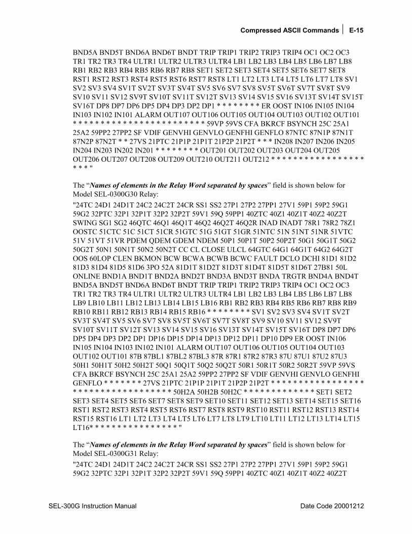
Compressed ASCII Commands E-15
SEL-300G Instruction Manual Date Code 20001212
BND5A BND5T BND6A BND6T BNDT TRIP TRIP1 TRIP2 TRIP3 TRIP4 OC1 OC2 OC3 TR1 TR2 TR3 TR4 ULTR1 ULTR2 ULTR3 ULTR4 LB1 LB2 LB3 LB4 LB5 LB6 LB7 LB8 RB1 RB2 RB3 RB4 RB5 RB6 RB7 RB8 SET1 SET2 SET3 SET4 SET5 SET6 SET7 SET8 RST1 RST2 RST3 RST4 RST5 RST6 RST7 RST8 LT1 LT2 LT3 LT4 LT5 LT6 LT7 LT8 SV1 SV2 SV3 SV4 SV1T SV2T SV3T SV4T SV5 SV6 SV7 SV8 SV5T SV6T SV7T SV8T SV9 SV10 SV11 SV12 SV9T SV10T SV11T SV12T SV13 SV14 SV15 SV16 SV13T SV14T SV15T SV16T DP8 DP7 DP6 DP5 DP4 DP3 DP2 DP1 * * * * * * * * ER OOST IN106 IN105 IN104 IN103 IN102 IN101 ALARM OUT107 OUT106 OUT105 OUT104 OUT103 OUT102 OUT101 * * * * * * * * * * * * * * * * * * * * * * * * 59VP 59VS CFA BKRCF BSYNCH 25C 25A1 25A2 59PP2 27PP2 SF VDIF GENVHI GENVLO GENFHI GENFLO 87NTC 87N1P 87N1T 87N2P 87N2T * * 27VS 21PTC 21P1P 21P1T 21P2P 21P2T * * * IN208 IN207 IN206 IN205 IN204 IN203 IN202 IN201 * * * * * * * * OUT201 OUT202 OUT203 OUT204 OUT205 OUT206 OUT207 OUT208 OUT209 OUT210 OUT211 OUT212 * * * * * * * * * * * * * * * * * * * * "
The Names of elements in the Relay Word separated by spaces field is shown below for Model SEL-0300G30 Relay: "24TC 24D1 24D1T 24C2 24C2T 24CR SS1 SS2 27P1 27P2 27PP1 27V1 59P1 59P2 59G1 59G2 32PTC 32P1 32P1T 32P2 32P2T 59V1 59Q 59PP1 40ZTC 40Z1 40Z1T 40Z2 40Z2T SWING SG1 SG2 46QTC 46Q1 46Q1T 46Q2 46Q2T 46Q2R INAD INADT 78R1 78R2 78Z1 OOSTC 51CTC 51C 51CT 51CR 51GTC 51G 51GT 51GR 51NTC 51N 51NT 51NR 51VTC 51V 51VT 51VR PDEM QDEM GDEM NDEM 50P1 50P1T 50P2 50P2T 50G1 50G1T 50G2 50G2T 50N1 50N1T 50N2 50N2T CC CL CLOSE ULCL 64GTC 64G1 64G1T 64G2 64G2T OOS 60LOP CLEN BKMON BCW BCWA BCWB BCWC FAULT DCLO DCHI 81D1 81D2 81D3 81D4 81D5 81D6 3PO 52A 81D1T 81D2T 81D3T 81D4T 81D5T 81D6T 27B81 50L ONLINE BND1A BND1T BND2A BND2T BND3A BND3T BNDA TRGTR BND4A BND4T BND5A BND5T BND6A BND6T BNDT TRIP TRIP1 TRIP2 TRIP3 TRIP4 OC1 OC2 OC3 TR1 TR2 TR3 TR4 ULTR1 ULTR2 ULTR3 ULTR4 LB1 LB2 LB3 LB4 LB5 LB6 LB7 LB8 LB9 LB10 LB11 LB12 LB13 LB14 LB15 LB16 RB1 RB2 RB3 RB4 RB5 RB6 RB7 RB8 RB9 RB10 RB11 RB12 RB13 RB14 RB15 RB16 * * * * * * * * SV1 SV2 SV3 SV4 SV1T SV2T SV3T SV4T SV5 SV6 SV7 SV8 SV5T SV6T SV7T SV8T SV9 SV10 SV11 SV12 SV9T SV10T SV11T SV12T SV13 SV14 SV15 SV16 SV13T SV14T SV15T SV16T DP8 DP7 DP6 DP5 DP4 DP3 DP2 DP1 DP16 DP15 DP14 DP13 DP12 DP11 DP10 DP9 ER OOST IN106 IN105 IN104 IN103 IN102 IN101 ALARM OUT107 OUT106 OUT105 OUT104 OUT103 OUT102 OUT101 87B 87BL1 87BL2 87BL3 87R 87R1 87R2 87R3 87U 87U1 87U2 87U3 50H1 50H1T 50H2 50H2T 50Q1 50Q1T 50Q2 50Q2T 50R1 50R1T 50R2 50R2T 59VP 59VS CFA BKRCF BSYNCH 25C 25A1 25A2 59PP2 27PP2 SF VDIF GENVHI GENVLO GENFHI GENFLO * * * * * * * 27VS 21PTC 21P1P 21P1T 21P2P 21P2T * * * * * * * * * * * * * * * * * * * * * * * * * * * * * * * * * * * 50H2A 50H2B 50H2C * * * * * * * * * * * * * SET1 SET2 SET3 SET4 SET5 SET6 SET7 SET8 SET9 SET10 SET11 SET12 SET13 SET14 SET15 SET16 RST1 RST2 RST3 RST4 RST5 RST6 RST7 RST8 RST9 RST10 RST11 RST12 RST13 RST14 RST15 RST16 LT1 LT2 LT3 LT4 LT5 LT6 LT7 LT8 LT9 LT10 LT11 LT12 LT13 LT14 LT15 LT16* * * * * * * * * * * * * * * * "
The Names of elements in the Relay Word separated by spaces field is shown below for Model SEL-0300G31 Relay: "24TC 24D1 24D1T 24C2 24C2T 24CR SS1 SS2 27P1 27P2 27PP1 27V1 59P1 59P2 59G1 59G2 32PTC 32P1 32P1T 32P2 32P2T 59V1 59Q 59PP1 40ZTC 40Z1 40Z1T 40Z2 40Z2T
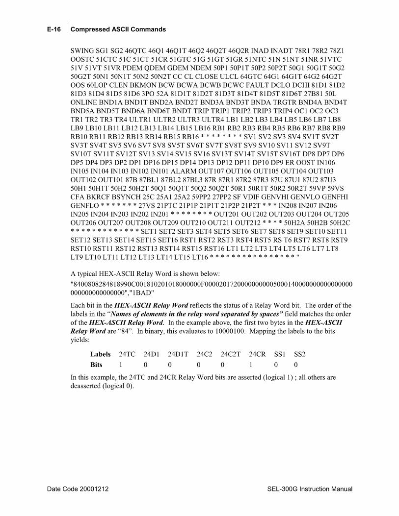
E-16 Compressed ASCII Commands
Date Code 20001212 SEL-300G Instruction Manual
SWING SG1 SG2 46QTC 46Q1 46Q1T 46Q2 46Q2T 46Q2R INAD INADT 78R1 78R2 78Z1 OOSTC 51CTC 51C 51CT 51CR 51GTC 51G 51GT 51GR 51NTC 51N 51NT 51NR 51VTC 51V 51VT 51VR PDEM QDEM GDEM NDEM 50P1 50P1T 50P2 50P2T 50G1 50G1T 50G2 50G2T 50N1 50N1T 50N2 50N2T CC CL CLOSE ULCL 64GTC 64G1 64G1T 64G2 64G2T OOS 60LOP CLEN BKMON BCW BCWA BCWB BCWC FAULT DCLO DCHI 81D1 81D2 81D3 81D4 81D5 81D6 3PO 52A 81D1T 81D2T 81D3T 81D4T 81D5T 81D6T 27B81 50L ONLINE BND1A BND1T BND2A BND2T BND3A BND3T BNDA TRGTR BND4A BND4T BND5A BND5T BND6A BND6T BNDT TRIP TRIP1 TRIP2 TRIP3 TRIP4 OC1 OC2 OC3 TR1 TR2 TR3 TR4 ULTR1 ULTR2 ULTR3 ULTR4 LB1 LB2 LB3 LB4 LB5 LB6 LB7 LB8 LB9 LB10 LB11 LB12 LB13 LB14 LB15 LB16 RB1 RB2 RB3 RB4 RB5 RB6 RB7 RB8 RB9 RB10 RB11 RB12 RB13 RB14 RB15 RB16 * * * * * * * * SV1 SV2 SV3 SV4 SV1T SV2T SV3T SV4T SV5 SV6 SV7 SV8 SV5T SV6T SV7T SV8T SV9 SV10 SV11 SV12 SV9T SV10T SV11T SV12T SV13 SV14 SV15 SV16 SV13T SV14T SV15T SV16T DP8 DP7 DP6 DP5 DP4 DP3 DP2 DP1 DP16 DP15 DP14 DP13 DP12 DP11 DP10 DP9 ER OOST IN106 IN105 IN104 IN103 IN102 IN101 ALARM OUT107 OUT106 OUT105 OUT104 OUT103 OUT102 OUT101 87B 87BL1 87BL2 87BL3 87R 87R1 87R2 87R3 87U 87U1 87U2 87U3 50H1 50H1T 50H2 50H2T 50Q1 50Q1T 50Q2 50Q2T 50R1 50R1T 50R2 50R2T 59VP 59VS CFA BKRCF BSYNCH 25C 25A1 25A2 59PP2 27PP2 SF VDIF GENVHI GENVLO GENFHI GENFLO * * * * * * * 27VS 21PTC 21P1P 21P1T 21P2P 21P2T * * * IN208 IN207 IN206 IN205 IN204 IN203 IN202 IN201 * * * * * * * * OUT201 OUT202 OUT203 OUT204 OUT205 OUT206 OUT207 OUT208 OUT209 OUT210 OUT211 OUT212 * * * * 50H2A 50H2B 50H2C * * * * * * * * * * * * * SET1 SET2 SET3 SET4 SET5 SET6 SET7 SET8 SET9 SET10 SET11 SET12 SET13 SET14 SET15 SET16 RST1 RST2 RST3 RST4 RST5 RS T6 RST7 RST8 RST9 RST10 RST11 RST12 RST13 RST14 RST15 RST16 LT1 LT2 LT3 LT4 LT5 LT6 LT7 LT8 LT9 LT10 LT11 LT12 LT13 LT14 LT15 LT16 * * * * * * * * * * * * * * * * "
A typical HEX-ASCII Relay Word is shown below: "8400808284818990C001810201018000000F00002017200000000005000140000000000000000000000000000000","1BAD"
Each bit in the HEX-ASCII Relay Word reflects the status of a Relay Word bit. The order of the labels in the Names of elements in the relay word separated by spaces field matches the order of the HEX-ASCII Relay Word. In the example above, the first two bytes in the HEX-ASCII Relay Word are 84. In binary, this evaluates to 10000100. Mapping the labels to the bits yields:
Labels 24TC 24D1 24D1T 24C2 24C2T 24CR SS1 SS2 Bits 1 0 0 0 0 1 0 0
In this example, the 24TC and 24CR Relay Word bits are asserted (logical 1) ; all others are deasserted (logical 0).

Modbus® RTU Communications Protocol F-1
SEL-300G Instruction Manual Date Code 20020206
APPENDIX F: MODBUS® RTU COMMUNICATIONS PROTOCOL
INTRODUCTION This appendix describes Modbus RTU communications features supported by the SEL-300G Relay communications port.
Complete specifications for the Modbus protocol are available from the Modicon web site at www.modicon.com.
Enable Modbus protocol using the serial port settings. When Modbus protocol is enabled, the relay switches the port to Modbus protocol and deactivates the ASCII protocol.
Modbus RTU is a binary protocol that permits communication between a single master device and multiple slave devices. The communication is half duplex; only one device transmits at a time. The master transmits a binary command that includes the address of the desired slave device. All of the slave devices receive the message, but only the slave device with the matching address responds.
The SEL-300G Relay Modbus communication allows a Modbus master device to:
• Acquire metering, monitoring, and event data from the relay.
• Control SEL-300G Relay output contacts and remote bits.
• Read the SEL-300G Relay self-test status and learn the present condition of all relay protection elements.
MODBUS RTU COMMUNICATIONS PROTOCOL
Modbus Queries Modbus RTU master devices initiate all exchanges by sending a query. The query consists of the fields shown in Table F.1.
Table F.1: Modbus Query Fields
Field Number of Bytes
Slave Device Address 1 byte Function Code 1 byte Data Region 0251 bytes Cyclical Redundancy Check (CRC) 2 bytes
The SEL-300G Relay SLAVEID setting defines the device address. Set this value to a unique number for each device on the Modbus network. For Modbus communication to operate properly, no two slave devices may have the same address.

F-2 Modbus® RTU Communications Protocol
Date Code 20020206 SEL-300G Instruction Manual
Function codes supported by the SEL-300G Relay are described in 0.
The cyclical redundancy check detects errors in the received data. If an error is detected, the relay discards the packet.
Modbus Responses The slave device sends a response message after it performs the action requested in the query. If the slave cannot execute the command for any reason, it sends an error response. Otherwise, the slave device response is formatted similarly to the query including the slave address, function code, data (if applicable), and a cyclical redundancy check value.
Supported Modbus Function Codes The SEL-300G Relay supports the Modbus function codes shown in Table F.2.
Table F.2: SEL-300G Relay Modbus Function Codes
Codes Description
01h Read Coil Status 02h Read Input Status 03h Read Holding Registers 04h Read Input Registers 05h Force Single Coil 06h Preset Single Register 07h Read Exception Status 08h Loopback Diagnostic Command 10h Preset Multiple Registers 64h Scattered Register Read

Modbus® RTU Communications Protocol F-3
SEL-300G Instruction Manual Date Code 20020206
Modbus Exception Responses The SEL-300G Relay sends an exception code under the conditions described in Table F.3.
Table F.3: SEL-300G Relay Modbus Exception Codes
Exception Code Error Type Description
01 Illegal Function Code The received function code is either undefined or unsupported.
02 Illegal Data Address The received command contains an unsupported address in the data field.
03 Illegal Data Value The received command contains a value that is out of range.
04 Device Error The SEL-300G Relay is in the wrong state for the requested function.
06 Busy The SEL-300G Relay is unable to process the command at this time due to a busy resource.
08 Memory Error Checksum error on stored data.
In the event that any of the errors listed in Table F.3 occur, the relay assembles a response message that includes the exception code in the data field. The relay sets the most significant bit in the function code field to indicate to the master that the data field contains an error code, instead of the requested data.
Cyclical Redundancy Check The SEL-300G Relay calculates a 2-byte CRC value using the device address, function code, and data fields. It appends this value to the end of every Modbus response. When the master device receives the response, it recalculates the CRC. If the calculated CRC matches the CRC sent by the SEL-300G Relay, the master device uses the data received. If there is not a match, the check fails and the message is ignored. The devices use a similar process when the master sends queries.
01h Read Coil Status Command Use function code 01h to read the On/Off status of the selected bits (coils). You may read the status of up to 2000 bits per query. Note that the relay coil addresses start at 0 (e.g., Coil 1 is located at address zero). The coil status is packed one coil per bit of the data field. The Least Significant Bit (LSB) of the first data byte contains the starting coil address in the query. The other coils follow towards the high order end of this byte and from low order to high order in subsequent bytes.

F-4 Modbus® RTU Communications Protocol
Date Code 20020206 SEL-300G Instruction Manual
Table F.4: 01h Read Coil Status Commands
Bytes Field Requests from the master must have the following format: 1 byte Slave Address 1 byte Function Code (01h) 2 bytes Address of the First Bit 2 bytes Number of Bits to Read 2 bytes CRC-16 A successful response from the slave will have the following format: 1 byte Slave Address 1 byte Function Code (01h) 1 byte Bytes of data (n) n bytes Data 2 bytes CRC-16
To build the response, the relay calculates the number of bytes required to contain the number of bits requested. If the number of bits requested is not evenly divisible by eight, the relay adds one more byte to maintain the balance of bits, padded by zeroes to make an even byte.
The relay responses to errors in the query are shown below:
Error Error Code Returned
Communication Counter Increments
Invalid bit to read
Illegal Data Address (02h)
Invalid Address
Invalid number of bits to read
Illegal Data Value (03h)
Illegal Register
Format error Illegal Data Value (03h)
Bad Packet Format
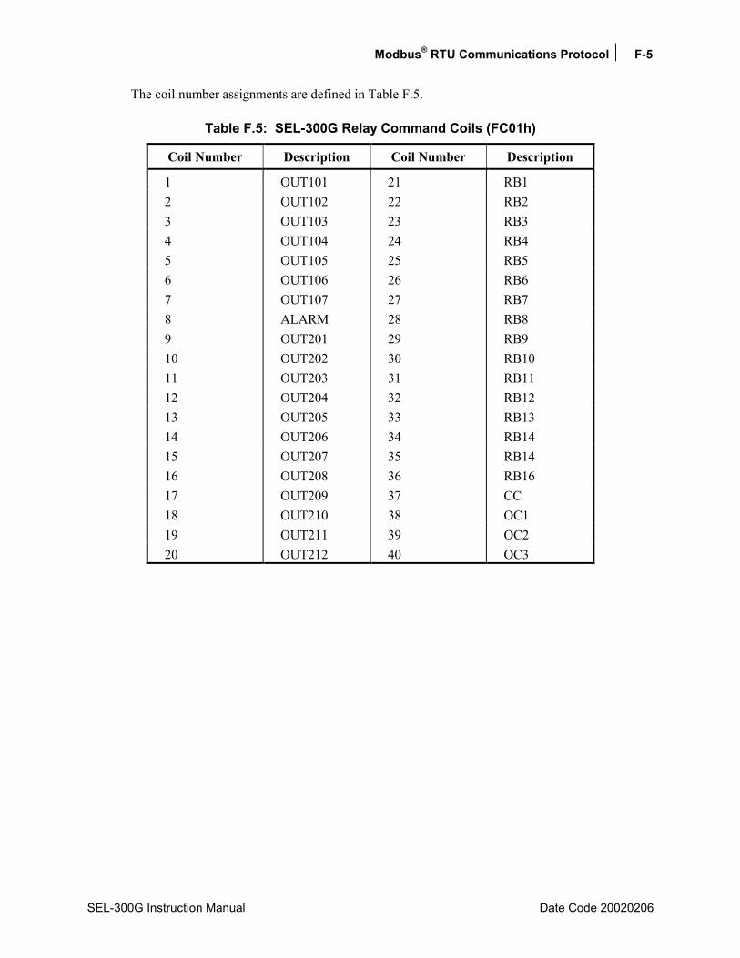
Modbus® RTU Communications Protocol F-5
SEL-300G Instruction Manual Date Code 20020206
The coil number assignments are defined in Table F.5.
Table F.5: SEL-300G Relay Command Coils (FC01h)
Coil Number Description Coil Number Description
1 OUT101 21 RB1 2 OUT102 22 RB2 3 OUT103 23 RB3 4 OUT104 24 RB4 5 OUT105 25 RB5 6 OUT106 26 RB6 7 OUT107 27 RB7 8 ALARM 28 RB8 9 OUT201 29 RB9 10 OUT202 30 RB10 11 OUT203 31 RB11 12 OUT204 32 RB12 13 OUT205 33 RB13 14 OUT206 34 RB14 15 OUT207 35 RB14 16 OUT208 36 RB16 17 OUT209 37 CC 18 OUT210 38 OC1 19 OUT211 39 OC2 20 OUT212 40 OC3
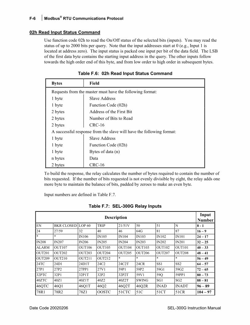
F-6 Modbus® RTU Communications Protocol
Date Code 20020206 SEL-300G Instruction Manual
02h Read Input Status Command Use function code 02h to read the On/Off status of the selected bits (inputs). You may read the status of up to 2000 bits per query. Note that the input addresses start at 0 (e.g., Input 1 is located at address zero). The input status is packed one input per bit of the data field. The LSB of the first data byte contains the starting input address in the query. The other inputs follow towards the high order end of this byte, and from low order to high order in subsequent bytes.
Table F.6: 02h Read Input Status Command
Bytes Field
Requests from the master must have the following format: 1 byte Slave Address 1 byte Function Code (02h) 2 bytes Address of the First Bit 2 bytes Number of Bits to Read 2 bytes CRC-16 A successful response from the slave will have the following format: 1 byte Slave Address 1 byte Function Code (02h) 1 byte Bytes of data (n) n bytes Data 2 bytes CRC-16
To build the response, the relay calculates the number of bytes required to contain the number of bits requested. If the number of bits requested is not evenly divisible by eight, the relay adds one more byte to maintain the balance of bits, padded by zeroes to make an even byte.
Input numbers are defined in Table F.7.
Table F.7: SEL-300G Relay Inputs
Description InputNumber
EN BKR CLOSED LOP 60 TRIP 21/51V 50 51 N 8 - 1 24 27/59 32 40 46 64G 81 87 16 9 * * IN106 IN105 IN104 IN103 IN102 IN101 24 17 IN208 IN207 IN206 IN205 IN204 IN203 IN202 IN201 32 25 ALARM OUT107 OUT106 OUT105 OUT104 OUT103 OUT102 OUT101 40 33 OUT201 OUT202 OUT203 OUT204 OUT205 OUT206 OUT207 OUT208 48 41 OUT209 OUT210 OUT211 OUT212 * * * * 56 49 24TC 24D1 24D1T 24C2 24C2T 24CR SS1 SS2 64 57 27P1 27P2 27PP1 27V1 59P1 59P2 59G1 59G2 72 65 32PTC 32P1 32P1T 32P2 32P2T 59V1 59Q 59PP1 80 73 40ZTC 40Z1 40Z1T 40Z2 40Z2T SWING SG1 SG2 88 81 46QTC 46Q1 46Q1T 46Q2 46Q2T 46Q2R INAD INADT 96 89 78R1 78R2 78Z1 OOSTC 51CTC 51C 51CT 51CR 104 97

Modbus® RTU Communications Protocol F-7
SEL-300G Instruction Manual Date Code 20020206
Description InputNumber
51GTC 51G 51GT 51GR 51NTC 51N 51NT 51NR 112 10551VTC 51V 51VT 51VR PDEM QDEM GDEM NDEM 120 11350P1 50P1T 50P2 50P2T 50G1 50G1T 50G2 50G2T 128 - 12150N1 50N1T 50N2 50N2T CC CL CLOSE ULCL 136 - 12964GTC 64G1 64G1T 64G2 64G2T OOS 60LOP CLEN 144 - 137BKMON BCW BCWA BCWB BCWC FAULT DCLO DCHI 152 - 14581D1 81D2 81D3 81D4 81D5 81D6 3PO 52A 160 - 15381D1T 81D2T 81D3T 81D4T 81D5T 81D6T 27B81 50L 168 - 161ONLINE BND1A BND1T BND2A BND2T BND3A BND3T BNDA 176 - 169TRGTR BND4A BND4T BND5A BND5T BND6A BND6T BNDT 184 - 177TRIP TRIP1 TRIP2 TRIP3 TRIP4 OC1 OC2 OC3 192 - 185TR1 TR2 TR3 TR4 ULTR1 ULTR2 ULTR3 ULTR4 200 - 193LB1 LB2 LB3 LB4 LB5 LB6 LB7 LB8 208 - 201LB9 LB10 LB11 LB12 LB13 LB14 LB15 LB16 216 - 209RB1 RB2 RB3 RB4 RB5 RB6 RB7 RB8 224 - 217RB9 RB10 RB11 RB12 RB13 RB14 RB15 RB16 232 - 225* * * * * * * * 240 - 233SV1 SV2 SV3 SV4 SV1T SV2T SV3T SV4T 248 - 241SV5 SV6 SV7 SV8 SV5T SV6T SV7T SV8T 256 - 249SV9 SV10 SV11 SV12 SV9T SV10T SV11T SV12T 264 - 257SV13 SV14 SV15 SV16 SV13T SV14T SV15T SV16T 272 - 265DP8 DP7 DP6 DP5 DP4 DP3 DP2 DP1 280 - 273DP16 DP15 DP14 DP13 DP12 DP11 DP10 DP9 288 - 281 ER OOST IN106 IN105 IN104 IN103 IN102 IN101 296 - 289 ALARM OUT107 OUT106 OUT105 OUT104 OUT103 OUT102 OUT101 304 - 297 87B 87BL1 87BL2 87BL3 87R 87R1 87R2 87R3 312 - 305 87U 87U1 87U2 87U3 50H1 50H1T 50H2 50H2T 320 - 313 50Q1 50Q1T 50Q2 50Q2T 50R1 50R1T 50R2 50R2T 328 - 321 59VP 59VS CFA BKRCF BSYNCH 25C 25A1 25A2 336 - 329 59PP2 27PP2 SF VDIF GENVHI GENVLO GENFHI GENFLO 344 - 337 87NTC 87N1P 87N1T 87N2P 87N2T * * 27VS 352 - 345 21PTC 21P1P 21P1T 21P2P 21P2T * * * 360 - 353 IN208 IN207 IN206 IN205 IN204 IN203 IN202 IN201 368 - 361 * * * * * * * * 376 - 369 OUT201 OUT202 OUT203 OUT204 OUT205 OUT206 OUT207 OUT208 384 - 377 OUT209 OUT210 OUT211 OUT212 * * * * 392 - 385 50H2A 50H2B 50H2C * * * * * 400 - 393 * * * * * * * * 408 - 401 SET1 SET2 SET3 SET4 SET5 SET6 SET7 SET8 416 - 409 SET9 SET10 SET11 SET12 SET13 SET14 SET15 SET16 424 - 417 RST1 RST2 RST3 RST4 RST5 RST6 RST7 RST8 432 - 425 RST9 RST10 RST11 RST12 RST13 RST14 RST15 RST16 440 - 433 LT1 LT2 LT3 LT4 LT5 LT6 LT7 LT8 448 - 441 LT9 LT10 LT11 LT12 LT13 LT14 LT15 LT16 456 - 449 OTHTRIP OTHALRM AMBTRIP AMBALRM BRGTRIP BRGALRM WDGTRIP WDGALRM 464 - 457 RTDFLT * * * * * * 2600IN 472 - 465
In each row, the input numbers are assigned from the right-most input to the left-most input (i.e., Input 1 is N and Input 8 is EN). Input addresses start at 0000 (i.e., Input 1 is located at Input Address 0000).
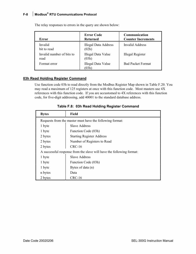
F-8 Modbus® RTU Communications Protocol
Date Code 20020206 SEL-300G Instruction Manual
The relay responses to errors in the query are shown below:
Error Error Code Returned
Communication Counter Increments
Invalid bit to read
Illegal Data Address (02h)
Invalid Address
Invalid number of bits to read
Illegal Data Value (03h)
Illegal Register
Format error Illegal Data Value (03h)
Bad Packet Format
03h Read Holding Register Command Use function code 03h to read directly from the Modbus Register Map shown in Table F.20. You may read a maximum of 125 registers at once with this function code. Most masters use 4X references with this function code. If you are accustomed to 4X references with this function code, for five-digit addressing, add 40001 to the standard database address.
Table F.8: 03h Read Holding Register Command
Bytes Field
Requests from the master must have the following format: 1 byte Slave Address 1 byte Function Code (03h) 2 bytes Starting Register Address 2 bytes Number of Registers to Read 2 bytes CRC-16 A successful response from the slave will have the following format: 1 byte Slave Address 1 byte Function Code (03h) 1 byte Bytes of data (n) n bytes Data 2 bytes CRC-16

Modbus® RTU Communications Protocol F-9
SEL-300G Instruction Manual Date Code 20020206
The relay responses to errors in the query are shown below:
Error Error Code Returned
Communication Counter Increments
Illegal register to read Illegal Data Address (02h)
Invalid Address
Illegal number of registers to read
Illegal Data Value (03h)
Illegal Register
Format error Illegal Data Value (03h)
Bad Packet Format
Busy Slave is busy with other task (06h)
04h Read Input Registers Command Use function code 04h to read from the Modbus Register Map shown in Table F.20. You may read a maximum of 125 registers at once with this function code. Most masters use 3X references with this function code. If you are accustomed to 3X references with this function code, for five-digit addressing, add 30001 to the standard database address.
Table F.9: 04h Read Holding Register Command
Bytes Field Requests from the master must have the following format: 1 byte Slave Address 1 byte Function Code (04h) 2 bytes Starting Register Address 2 bytes Number of Registers to Read 2 bytes CRC-16 A successful response from the slave will have the following format: 1 byte Slave Address 1 byte Function Code (04h) 1 byte Bytes of data (n) n bytes Data 2 bytes CRC-16
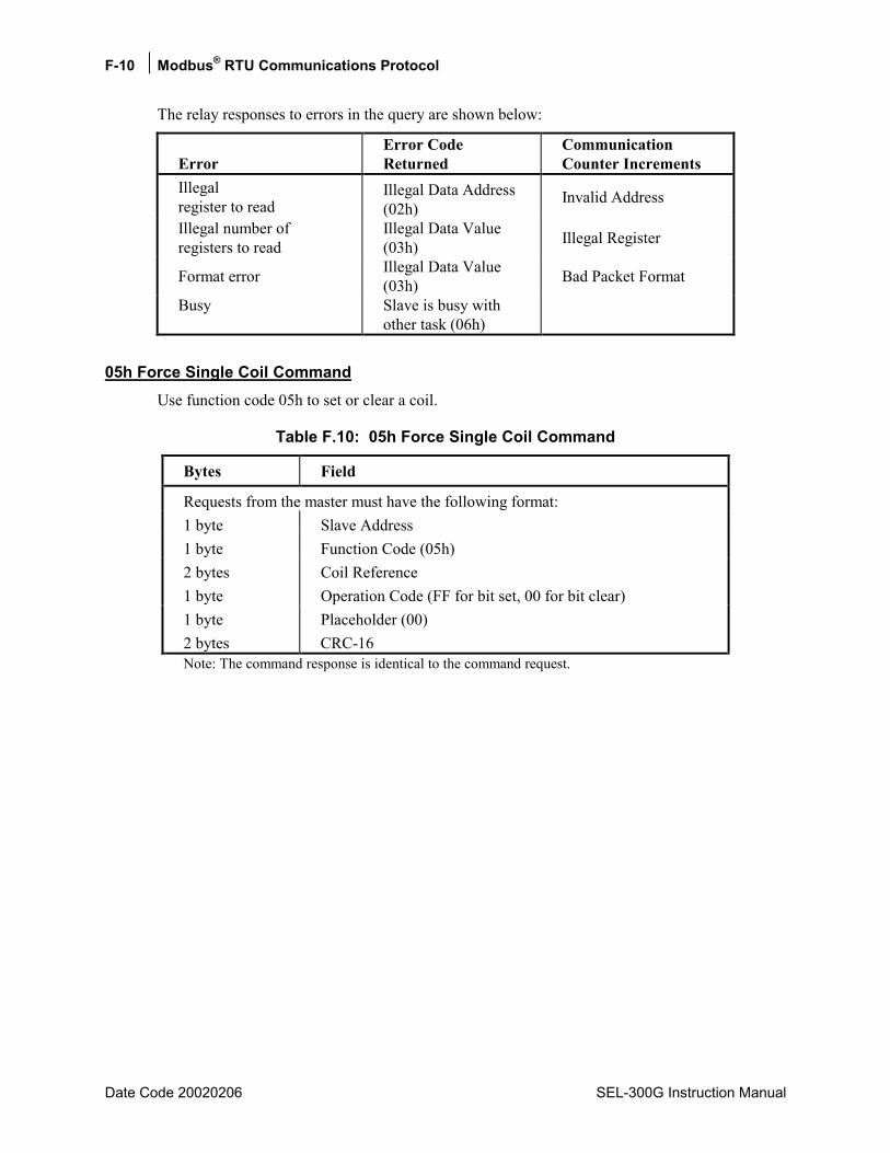
F-10 Modbus® RTU Communications Protocol
Date Code 20020206 SEL-300G Instruction Manual
The relay responses to errors in the query are shown below:
Error Error Code Returned
Communication Counter Increments
Illegal register to read
Illegal Data Address (02h)
Invalid Address
Illegal number of registers to read
Illegal Data Value (03h) Illegal Register
Format error Illegal Data Value (03h) Bad Packet Format
Busy Slave is busy with other task (06h)
05h Force Single Coil Command Use function code 05h to set or clear a coil.
Table F.10: 05h Force Single Coil Command
Bytes Field
Requests from the master must have the following format: 1 byte Slave Address 1 byte Function Code (05h) 2 bytes Coil Reference 1 byte Operation Code (FF for bit set, 00 for bit clear) 1 byte Placeholder (00) 2 bytes CRC-16 Note: The command response is identical to the command request.
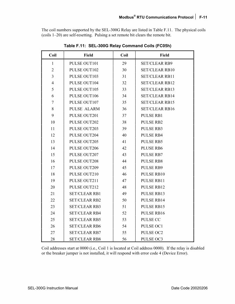
Modbus® RTU Communications Protocol F-11
SEL-300G Instruction Manual Date Code 20020206
The coil numbers supported by the SEL-300G Relay are listed in Table F.11. The physical coils (coils 120) are self-resetting. Pulsing a set remote bit clears the remote bit.
Table F.11: SEL-300G Relay Command Coils (FC05h)
Coil Field Coil Field
1 PULSE OUT101 29 SET/CLEAR RB9 2 PULSE OUT102 30 SET/CLEAR RB10 3 PULSE OUT103 31 SET/CLEAR RB11 4 PULSE OUT104 32 SET/CLEAR RB12 5 PULSE OUT105 33 SET/CLEAR RB13 6 PULSE OUT106 34 SET/CLEAR RB14 7 PULSE OUT107 35 SET/CLEAR RB15 8 PULSE ALARM 36 SET/CLEAR RB16 9 PULSE OUT201 37 PULSE RB1
10 PULSE OUT202 38 PULSE RB2 11 PULSE OUT203 39 PULSE RB3 12 PULSE OUT204 40 PULSE RB4 13 PULSE OUT205 41 PULSE RB5 14 PULSE OUT206 42 PLUSE RB6 15 PULSE OUT207 43 PULSE RB7 16 PULSE OUT208 44 PULSE RB8 17 PULSE OUT209 45 PULSE RB9 18 PULSE OUT210 46 PULSE RB10 19 PULSE OUT211 47 PULSE RB11 20 PULSE OUT212 48 PULSE RB12 21 SET/CLEAR RB1 49 PULSE RB13 22 SET/CLEAR RB2 50 PULSE RB14 23 SET/CLEAR RB3 51 PULSE RB15 24 SET/CLEAR RB4 52 PULSE RB16 25 SET/CLEAR RB5 53 PULSE CC 26 SET/CLEAR RB6 54 PULSE OC1 27 SET/CLEAR RB7 55 PULSE OC2 28 SET/CLEAR RB8 56 PULSE OC3
Coil addresses start at 0000 (i.e., Coil 1 is located at Coil address 0000). If the relay is disabled or the breaker jumper is not installed, it will respond with error code 4 (Device Error).
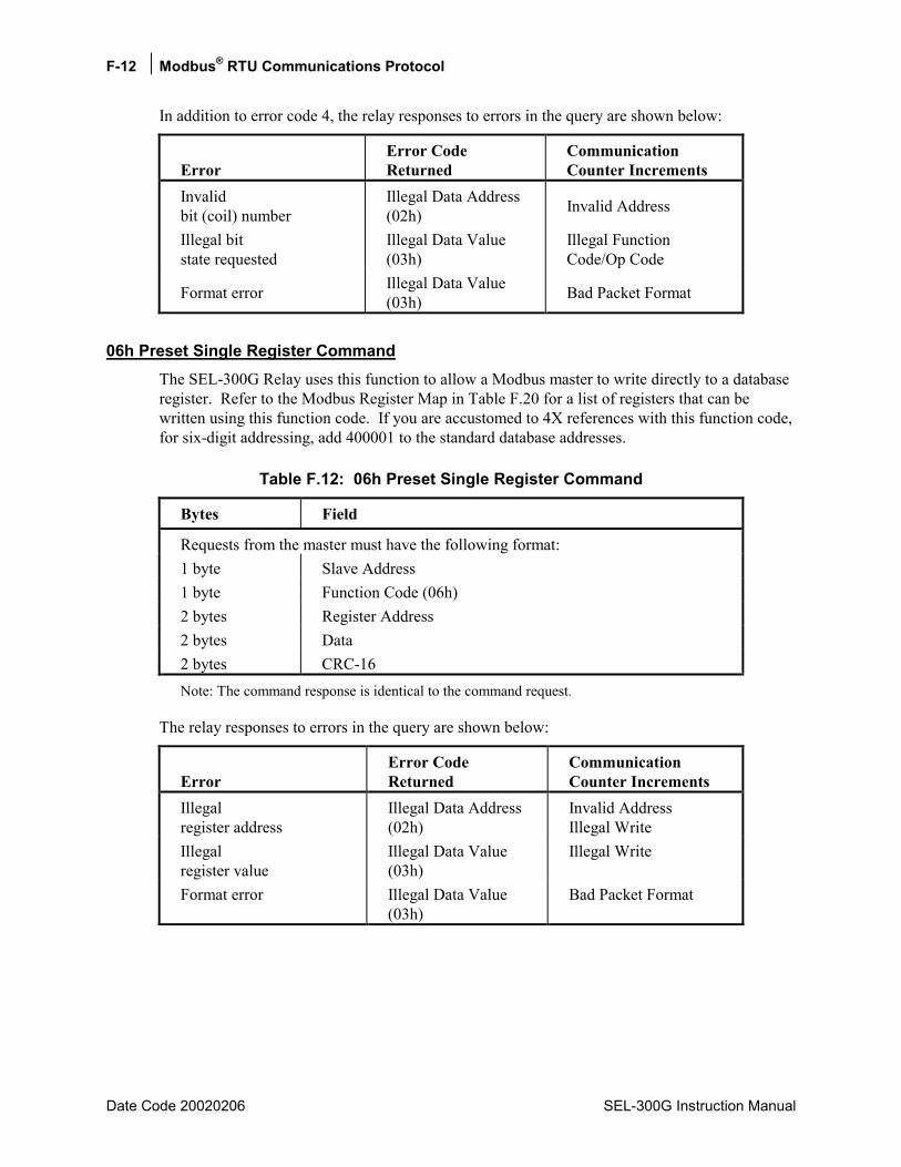
F-12 Modbus® RTU Communications Protocol
Date Code 20020206 SEL-300G Instruction Manual
In addition to error code 4, the relay responses to errors in the query are shown below:
Error Error Code Returned
Communication Counter Increments
Invalid bit (coil) number
Illegal Data Address (02h) Invalid Address
Illegal bit state requested
Illegal Data Value (03h)
Illegal Function Code/Op Code
Format error Illegal Data Value (03h) Bad Packet Format
06h Preset Single Register Command The SEL-300G Relay uses this function to allow a Modbus master to write directly to a database register. Refer to the Modbus Register Map in Table F.20 for a list of registers that can be written using this function code. If you are accustomed to 4X references with this function code, for six-digit addressing, add 400001 to the standard database addresses.
Table F.12: 06h Preset Single Register Command
Bytes Field
Requests from the master must have the following format: 1 byte Slave Address 1 byte Function Code (06h) 2 bytes Register Address 2 bytes Data 2 bytes CRC-16 Note: The command response is identical to the command request.
The relay responses to errors in the query are shown below:
Error Error Code Returned
Communication Counter Increments
Illegal register address
Illegal Data Address (02h)
Invalid Address Illegal Write
Illegal register value
Illegal Data Value (03h)
Illegal Write
Format error Illegal Data Value (03h)
Bad Packet Format

Modbus® RTU Communications Protocol F-13
SEL-300G Instruction Manual Date Code 20020206
07h Read Exception Status Command The SEL-300G Relay uses this function to allow a Modbus master to read the present status of the relay and protected circuit.
Table F.13: 07h Read Exception Status Command
Bytes Field Requests from the master must have the following format: 1 byte Slave Address 1 byte Function Code (07h) 0 bytes No Data Fields Are Sent 2 bytes CRC-16 A successful response from the slave will have the following format: 1 byte Slave Address 1 byte Function Code (07h) 1 byte Status Byte 2 bytes CRC-16 The status byte is sent least significant bit first, and consists of the following bits: Bit 0 OUT1 Status Bit 1 OUT2 Status Bit 2 OUT3 Status Bit 3 OUT4 Status Bit 4 Alarm Output status Bit 5 Input 1 Status Bit 6 Input 2 Status Bit 7 Relay Status
If the status bit is set to 1, the following are true for the status indicated by the bit:
• Alarm contact is asserted.
• Relay is disabled.
If the status bit is set to 0, the following are true for the status indicated by the bit:
• Alarm contact is deasserted.
• Relay is enabled.
The relay response to errors in the query is shown below:
Error Error Code Returned
Communication Counter Increments
Format error Illegal Data Value (03h)
Bad Packet Format

F-14 Modbus® RTU Communications Protocol
Date Code 20020206 SEL-300G Instruction Manual
08h Loopback Diagnostic Command The SEL-300G Relay uses this function to allow a Modbus master to perform a diagnostic test on the Modbus communications channel and relay. When the subfunction field is 0000h, the relay returns a replica of the received message.
Table F.14: 08h Loopback Diagnostic Command
Bytes Field Requests from the master must have the following format: 1 byte Slave Address 1 byte Function Code (08h) 2 bytes Subfunction (0000h) 2 bytes Data Field 2 bytes CRC-16 A successful response from the slave will have the following format: 1 byte Slave Address 1 byte Function Code (08h) 2 bytes Subfunction (0000h) 2 bytes Data Field (identical to data in Master request) 2 bytes CRC-16
The relay responses to errors in the query are shown below:
Error Error Code Returned
Communication Counter Increments
Illegal subfunction code Illegal Data Value (03h)
Illegal Function Code/Op Code
Format error Illegal Data Value (03h) Bad Packet Format
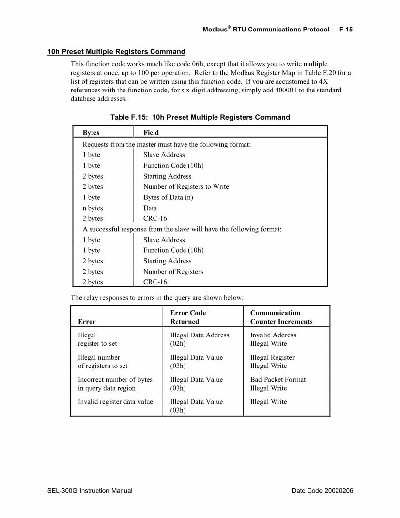
Modbus® RTU Communications Protocol F-15
SEL-300G Instruction Manual Date Code 20020206
10h Preset Multiple Registers Command This function code works much like code 06h, except that it allows you to write multiple registers at once, up to 100 per operation. Refer to the Modbus Register Map in Table F.20 for a list of registers that can be written using this function code. If you are accustomed to 4X references with the function code, for six-digit addressing, simply add 400001 to the standard database addresses.
Table F.15: 10h Preset Multiple Registers Command
Bytes Field Requests from the master must have the following format: 1 byte Slave Address 1 byte Function Code (10h) 2 bytes Starting Address 2 bytes Number of Registers to Write 1 byte Bytes of Data (n) n bytes Data 2 bytes CRC-16 A successful response from the slave will have the following format: 1 byte Slave Address 1 byte Function Code (10h) 2 bytes Starting Address 2 bytes Number of Registers 2 bytes CRC-16
The relay responses to errors in the query are shown below:
Error Error Code Returned
Communication Counter Increments
Illegal register to set
Illegal Data Address (02h)
Invalid Address Illegal Write
Illegal number of registers to set
Illegal Data Value (03h)
Illegal Register Illegal Write
Incorrect number of bytes in query data region
Illegal Data Value (03h)
Bad Packet Format Illegal Write
Invalid register data value Illegal Data Value (03h)
Illegal Write
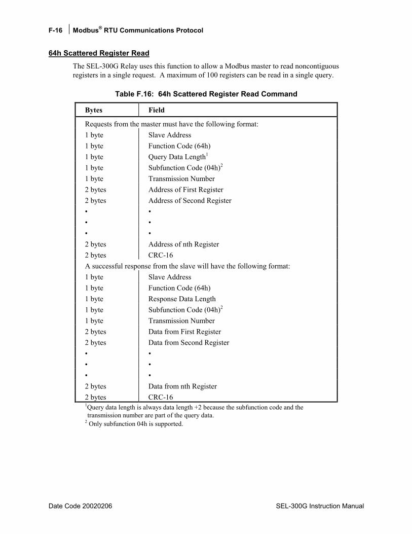
F-16 Modbus® RTU Communications Protocol
Date Code 20020206 SEL-300G Instruction Manual
64h Scattered Register Read The SEL-300G Relay uses this function to allow a Modbus master to read noncontiguous registers in a single request. A maximum of 100 registers can be read in a single query.
Table F.16: 64h Scattered Register Read Command
Bytes Field
Requests from the master must have the following format: 1 byte Slave Address 1 byte Function Code (64h) 1 byte Query Data Length1 1 byte Subfunction Code (04h)2 1 byte Transmission Number 2 bytes Address of First Register 2 bytes Address of Second Register 2 bytes Address of nth Register 2 bytes CRC-16 A successful response from the slave will have the following format: 1 byte Slave Address 1 byte Function Code (64h) 1 byte Response Data Length 1 byte Subfunction Code (04h)2 1 byte Transmission Number 2 bytes Data from First Register 2 bytes Data from Second Register 2 bytes Data from nth Register 2 bytes CRC-16 1Query data length is always data length +2 because the subfunction code and the transmission number are part of the query data.
2 Only subfunction 04h is supported.
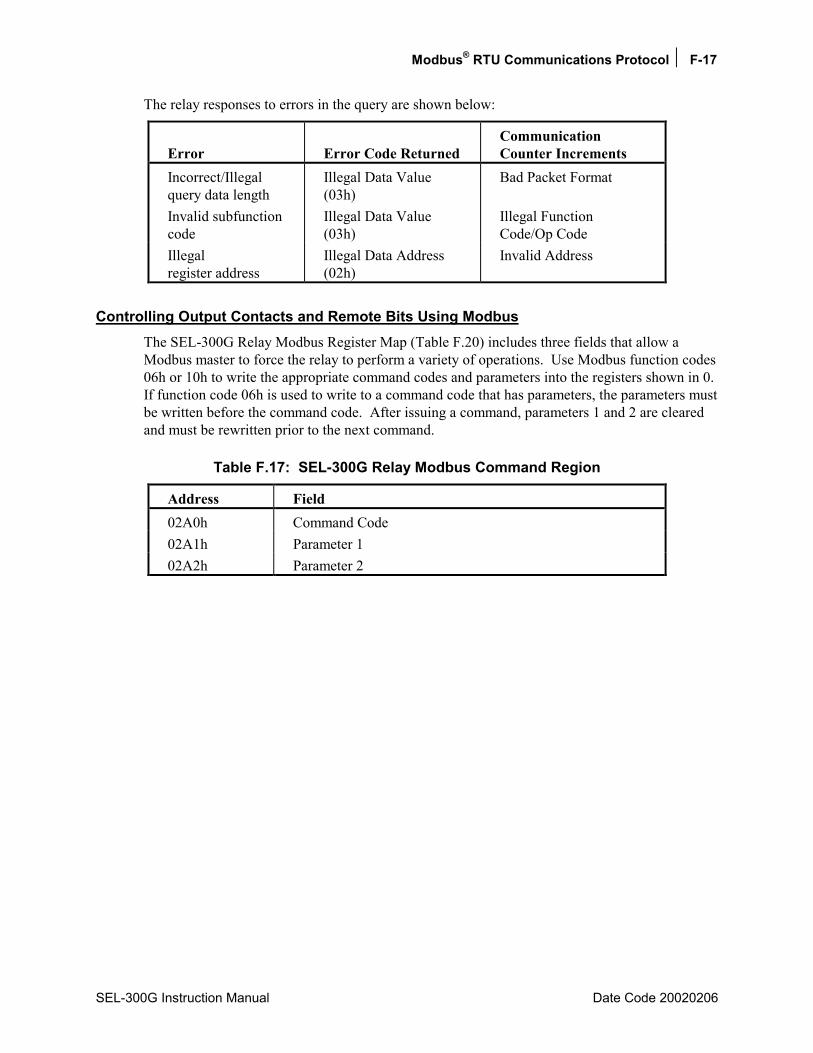
Modbus® RTU Communications Protocol F-17
SEL-300G Instruction Manual Date Code 20020206
The relay responses to errors in the query are shown below:
Error Error Code Returned Communication Counter Increments
Incorrect/Illegal query data length
Illegal Data Value (03h)
Bad Packet Format
Invalid subfunction code
Illegal Data Value (03h)
Illegal Function Code/Op Code
Illegal register address
Illegal Data Address (02h)
Invalid Address
Controlling Output Contacts and Remote Bits Using Modbus The SEL-300G Relay Modbus Register Map (Table F.20) includes three fields that allow a Modbus master to force the relay to perform a variety of operations. Use Modbus function codes 06h or 10h to write the appropriate command codes and parameters into the registers shown in 0. If function code 06h is used to write to a command code that has parameters, the parameters must be written before the command code. After issuing a command, parameters 1 and 2 are cleared and must be rewritten prior to the next command.
Table F.17: SEL-300G Relay Modbus Command Region
Address Field 02A0h Command Code 02A1h Parameter 1 02A2h Parameter 2

F-18 Modbus® RTU Communications Protocol
Date Code 20020206 SEL-300G Instruction Manual
Table F.18 defines the command codes, their function and associated parameters, and the Modbus function code used to initiate the related command code.
Table F.18: Modbus Command Codes
Command Code Function Parameter Definition
Modbus Function Code
01 Open Breaker 1 No Parameter 06h, 10h 02 Open Breaker 2 No Parameter 06h, 10h 03 Open Breaker 3 No Parameter 06h, 10h 04 Close Breaker 1 No Parameter 06h, 10h 05 Reset Targets No Parameter 06h, 10h 06 Trigger No Parameter 06h, 10h 07 Pulse OUT101 130 seconds duration (defaults to 1 second) 06h, 10h 08 Pulse OUT102 130 seconds duration (defaults to 1 second) 06h, 10h 09 Pulse OUT103 130 seconds duration (defaults to 1 second) 06h, 10h 10 Pulse OUT104 130 seconds duration (defaults to 1 second) 06h, 10h 11 Pulse OUT105 130 seconds duration (defaults to 1 second) 06h, 10h 12 Pulse OUT106 130 seconds duration (defaults to 1 second) 06h, 10h 13 Pulse OUT107 130 seconds duration (defaults to 1 second) 06h, 10h 14 Pulse Alarm 130 seconds duration (defaults to 1 second) 06h, 10h 15 Pulse OUT201 130 seconds duration (defaults to 1 second) 06h, 10h 16 Pulse OUT202 130 seconds duration (defaults to 1 second) 06h, 10h 17 Pulse OUT203 130 seconds duration (defaults to 1 second) 06h, 10h 18 Pulse OUT204 130 seconds duration (defaults to 1 second) 06h, 10h 19 Pulse OUT205 130 seconds duration (defaults to 1 second) 06h, 10h 20 Pulse OUT206 130 seconds duration (defaults to 1 second) 06h, 10h 21 Pulse OUT207 130 seconds duration (defaults to 1 second) 06h, 10h 22 Pulse OUT208 130 seconds duration (defaults to 1 second) 06h, 10h 23 Pulse OUT209 130 seconds duration (defaults to 1 second) 06h, 10h 24 Pulse OUT210 130 seconds duration (defaults to 1 second) 06h, 10h 25 Pulse OUT211 130 seconds duration (defaults to 1 second) 06h, 10h 26 Pulse OUT212 130 seconds duration (defaults to 1 second) 06h, 10h 27 Change Act.
Group 1-2 06h, 10h
28 Switch Protocol 0080h 06h, 10h

Modbus® RTU Communications Protocol F-19
SEL-300G Instruction Manual Date Code 20020206
Command Code Function Parameter Definition
Modbus Function Code
29 Reset Data Regions
0000 0000 0000 0001 Demand Metering 0000 0000 0000 0010 Peak Demand Metering 0000 0000 0000 0100 Energy Values 0000 0000 0000 1000 Max/Min meter values 0000 0000 0001 0000 Breaker Monitor 0000 0000 0010 0000 History Buffer (history
and events) 0000 0000 0100 0000 Targets 0000 0000 1000 0000 Sync Check 0000 0001 0000 0000 SER 0000 0010 0000 0000 Communication
Counters 0000 0100 0000 0000 Profiles
06h, 10h
30 Control Remote Bits
See Note 06h, 10h
Note Command Code 30Control Remote Bits This code controls the remote bits. This command code has two parameters: Parameter 1 determines the bit operation.
Value Operation 1 Set 2 Clear 3 Pulse (1/4 cycle)
Parameter 2 determines which bit to control. It is bitmasked for future expansion, but only one bit can be controlled at a time. The highest numbered bit will be controlled if more than one bit occurs in the parameter.
Bit Pattern Remote Bit Bit Pattern Remote Bit 0000 0000 0000 0001 RB1 0000 0001 0000 0000 RB9 0000 0000 0000 0010 RB2 0000 0010 0000 0000 RB10 0000 0000 0000 0100 RB3 0000 0100 0000 0000 RB11 0000 0000 0000 1000 RB4 0000 1000 0000 0000 RB12 0000 0000 0001 0000 RB5 0001 0000 0000 0000 RB13 0000 0000 0010 0000 RB6 0010 0000 0000 0000 RB14 0000 0000 0100 0000 RB7 0100 0000 0000 0000 RB15 0000 0000 1000 0000 RB8 1000 0000 0000 0000 RB16

F-20 Modbus® RTU Communications Protocol
Date Code 20020206 SEL-300G Instruction Manual
Error Codes In addition to the error codes returned for function codes 06h or 10h, the following error codes are returned for command codes.
• If the relay is disabled or if the breaker jumper is not installed while the commands 14 and 726 are issued, the relay will return error code 04 (device error).
• If the relay is disabled while Reset Targets command (05) is issued, the relay will return error code 04h (device error).
• If the TRIGGER command (06) cannot be executed due to multiple events in progress, the relay will return error code 06h (device busy). If the relay is disabled while this command is issued, the relay will return 04h (device error).
• If the Switch Protocol command (28) or Reset command (29) cannot be executed if the relay is busy, it will return error code 06h (device busy).
Reading Event Data Using Modbus The Modbus Register Map (Table F.20) provides a feature that allows you to download complete event data via Modbus. The SEL-300G Relay stores the 29 latest event summaries and the 29 latest 15-cycle or the 15 latest 30-cycle full-length event reports. Please refer to Section 11: Event Reports and SER Functions for a detailed description.
The event report will contain both analog and digital data. To download the event data using Modbus, proceed as follows:
1. Write the event number you wish to download at address 02D1h.
2. Write the channel number you wish to download at address 02D2h. Refer to Table F.19 for the channel number assignment.
3. Read the four-sample per cycle raw event data from the Modbus Map.
Note that reading event data via Modbus is significantly slower compared to the other data in the Modbus Register Map (Table F.20). Typical response time to read a single channel data via Modbus is about 11 seconds when accessing the new event report for the first time. Subsequent channels with the same event report will be less than 100 ms at 9600 baud rate.
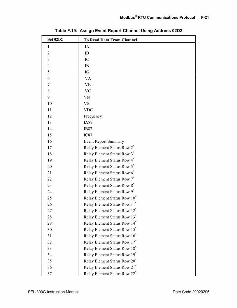
Modbus® RTU Communications Protocol F-21
SEL-300G Instruction Manual Date Code 20020206
Table F.19: Assign Event Report Channel Using Address 02D2
Set 02D2 To Read Data From Channel 1 IA 2 IB 3 IC 4 IN 5 IG 6 VA 7 VB 8 VC 9 VN 10 VS 11 VDC 12 Frequency 13 IA87 14 IB87 15 IC87 16 Event Report Summary 17 Relay Element Status Row 2* 18 Relay Element Status Row 3* 19 Relay Element Status Row 4* 20 Relay Element Status Row 5* 21 Relay Element Status Row 6* 22 Relay Element Status Row 7* 23 Relay Element Status Row 8* 24 Relay Element Status Row 9* 25 Relay Element Status Row 10* 26 Relay Element Status Row 11* 27 Relay Element Status Row 12* 28 Relay Element Status Row 13* 28 Relay Element Status Row 14* 30 Relay Element Status Row 15* 31 Relay Element Status Row 16* 32 Relay Element Status Row 17* 33 Relay Element Status Row 18* 34 Relay Element Status Row 19* 35 Relay Element Status Row 20* 36 Relay Element Status Row 21* 37 Relay Element Status Row 22*

F-22 Modbus® RTU Communications Protocol
Date Code 20020206 SEL-300G Instruction Manual
Set 02D2 To Read Data From Channel 38 Relay Element Status Row 23* 39 Relay Element Status Row 24* 40 Relay Element Status Row 25* 41 Relay Element Status Row 26* 42 Relay Element Status Row 27* 43 Relay Element Status Row 28* 44 Relay Element Status Row 29* 45 Relay Element Status Row 30* 46 Relay Element Status Row 31* 47 Relay Element Status Row 32* 48 Relay Element Status Row 33* 49 Relay Element Status Row 34* 50 Relay Element Status Row 35* 51 Relay Element Status Row 36* 52 Relay Element Status Row 37* 53 Relay Element Status Row 38* 54 Relay Element Status Row 39* 55 Relay Element Status Row 40* 56 Relay Element Status Row 41* 57 Relay Element Status Row 42* 58 Relay Element Status Row 43* 59 Relay Element Status Row 44* 60 Relay Element Status Row 45* 61 Relay Element Status Row 46* 62 Relay Element Status Row 47* 63 Relay Element Status Row 48* 64 Relay Element Status Row 49* 65 Relay Element Status Row 50* 66 Relay Element Status Row 51* 67 Relay Element Status Row 52* 68 Relay Element Status Row 53* * Please refer to Section 4: SELOGIC Control Equation to obtain the contents of each relay element status row. Relay Element Status Rows 0 and 1, which represents targets, are displayed at 0260h and 0261h in the Modbus Register Map.
If the user selects an event number for which there is no data available, 8000h will be returned.
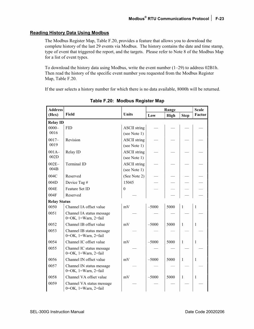
Modbus® RTU Communications Protocol F-23
SEL-300G Instruction Manual Date Code 20020206
Reading History Data Using Modbus The Modbus Register Map, Table F.20, provides a feature that allows you to download the complete history of the last 29 events via Modbus. The history contains the date and time stamp, type of event that triggered the report, and the targets. Please refer to Note 8 of the Modbus Map for a list of event types.
To download the history data using Modbus, write the event number (129) to address 02B1h. Then read the history of the specific event number you requested from the Modbus Register Map, Table F.20.
If the user selects a history number for which there is no data available, 8000h will be returned.
Table F.20: Modbus Register Map
Range Address (Hex) Field Units Low High Step
Scale Factor
Relay ID 0000 0016
FID ASCII string(see Note 1)
0017 0019
Revision ASCII string(see Note 1)
001A 002D
Relay ID ASCII string(see Note 1)
002E 004B
Terminal ID ASCII string(see Note 1)
004C Reserved (See Note 2) 004D Device Tag # 15045 004E Feature Set ID 0 004F Reserved Relay Status 0050 Channel IA offset value mV 5000 5000 1 1 0051 Channel IA status message
0=OK, 1=Warn, 2=fail
0052 Channel IB offset value mV 5000 5000 1 1 0053 Channel IB status message
0=OK, 1=Warn, 2=fail
0054 Channel IC offset value mV 5000 5000 1 1 0055 Channel IC status message
0=OK, 1=Warn, 2=fail
0056 Channel IN offset value mV 5000 5000 1 1 0057 Channel IN status message
0=OK, 1=Warn, 2=fail
0058 Channel VA offset value mV 5000 5000 1 1 0059 Channel VA status message
0=OK, 1=Warn, 2=fail
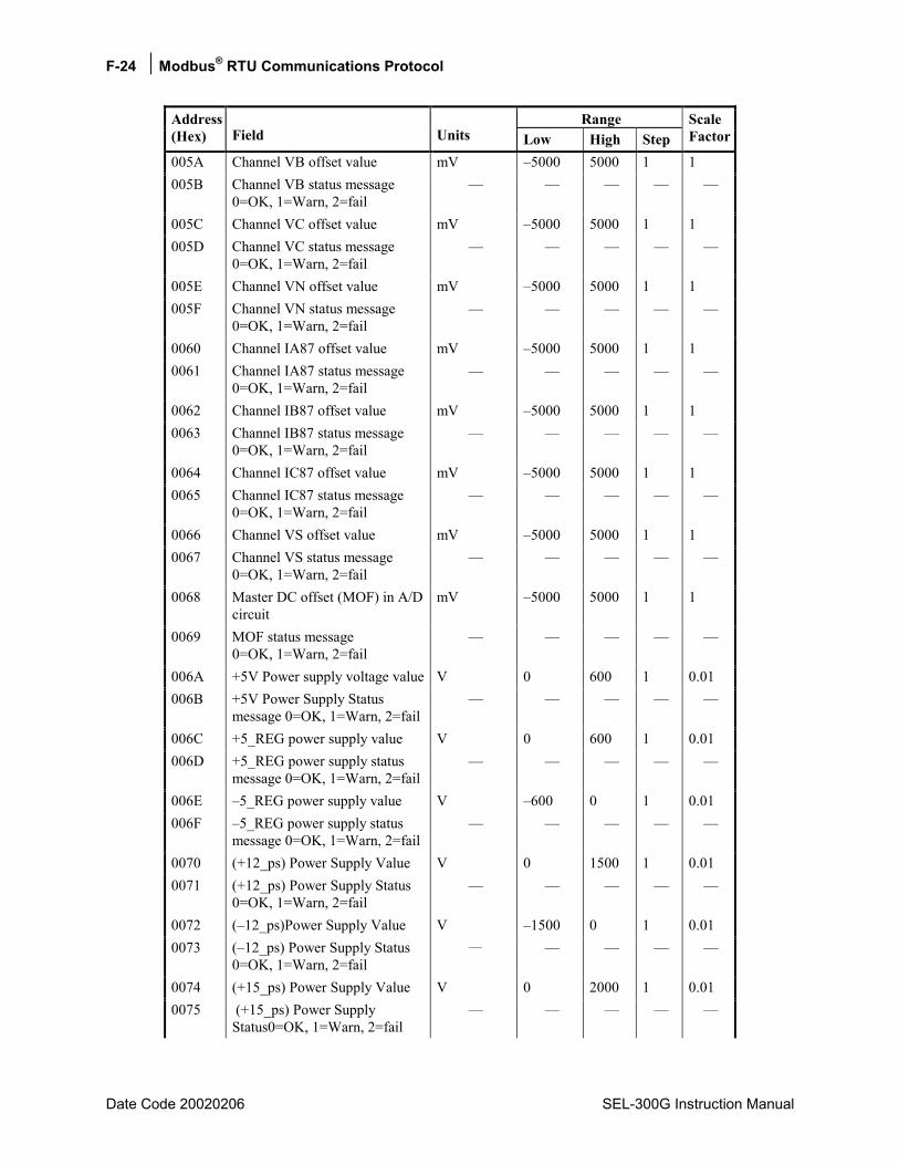
F-24 Modbus® RTU Communications Protocol
Date Code 20020206 SEL-300G Instruction Manual
Range Address (Hex) Field Units Low High Step
Scale Factor
005A Channel VB offset value mV 5000 5000 1 1 005B Channel VB status message
0=OK, 1=Warn, 2=fail
005C Channel VC offset value mV 5000 5000 1 1 005D Channel VC status message
0=OK, 1=Warn, 2=fail
005E Channel VN offset value mV 5000 5000 1 1 005F Channel VN status message
0=OK, 1=Warn, 2=fail
0060 Channel IA87 offset value mV 5000 5000 1 1 0061 Channel IA87 status message
0=OK, 1=Warn, 2=fail
0062 Channel IB87 offset value mV 5000 5000 1 1 0063 Channel IB87 status message
0=OK, 1=Warn, 2=fail
0064 Channel IC87 offset value mV 5000 5000 1 1 0065 Channel IC87 status message
0=OK, 1=Warn, 2=fail
0066 Channel VS offset value mV 5000 5000 1 1 0067 Channel VS status message
0=OK, 1=Warn, 2=fail
0068 Master DC offset (MOF) in A/D circuit
mV 5000 5000 1 1
0069 MOF status message 0=OK, 1=Warn, 2=fail
006A +5V Power supply voltage value V 0 600 1 0.01 006B +5V Power Supply Status
message 0=OK, 1=Warn, 2=fail
006C +5_REG power supply value V 0 600 1 0.01 006D +5_REG power supply status
message 0=OK, 1=Warn, 2=fail
006E 5_REG power supply value V 600 0 1 0.01 006F 5_REG power supply status
message 0=OK, 1=Warn, 2=fail
0070 (+12_ps) Power Supply Value V 0 1500 1 0.01 0071 (+12_ps) Power Supply Status
0=OK, 1=Warn, 2=fail
0072 (12_ps)Power Supply Value V 1500 0 1 0.01 0073 (12_ps) Power Supply Status
0=OK, 1=Warn, 2=fail
0074 (+15_ps) Power Supply Value V 0 2000 1 0.01 0075 (+15_ps) Power Supply
Status0=OK, 1=Warn, 2=fail

Modbus® RTU Communications Protocol F-25
SEL-300G Instruction Manual Date Code 20020206
Range Address (Hex) Field Units Low High Step
Scale Factor
0076 (15_ps) Power Supply Value V 2000 0 1 0.01 0077 (15_ps) Power Supply Status
0=OK, 1=Warn, 2=fail
0078 TEMP in degrees Celsius °C 1000 1000 1 0.1 0079 Temperature status
0=OK, 1=Warn, 2=fail
007A RAM status 0=OK, 2=fail
007B ROM status 0=OK, 2=fail
007C A/D 0=OK, 1=Warn, 2=fail
007D CR_RAM status 0=OK, 2=fail
007E EEPROM status 0=OK, 2=fail
007F IO Board 0=OK, 2=fail
0080 RELAY STATUS 0=Enabled, 2= Disabled
0081 008F
Reserved
Instantaneous Metering 0090 Phase A Current Amps 0 65535 1 1 0091 Phase A Current Angle degrees 18000 18000 1 0.01 0092 Phase B Current Amps 0 65535 1 1 0093 Phase B Current Angle degrees 18000 18000 1 0.01 0094 Phase C Current Amps 0 65535 1 1 0095 Phase C Current Angle degrees 18000 18000 1 0.01 0096 Neutral Current Amps 0 65535 1 1 0097 Neutral Current Angle degrees 18000 18000 1 0.01 0098 Residual Current Amps 0 65535 1 1 0099 Residual Current Angle degrees 18000 18000 1 0.01 009A Phase A Voltage kV 0 65535 1 0.1 009B Phase A Voltage Angle degrees 18000 18000 1 0.01 009C Phase B Voltage kV 0 65535 1 0.1 009D Phase B Voltage Angle degrees 18000 18000 1 0.01 009E Phase C Voltage kV 0 65535 1 0.1 009F Phase C Voltage Angle degrees 18000 18000 1 0.01
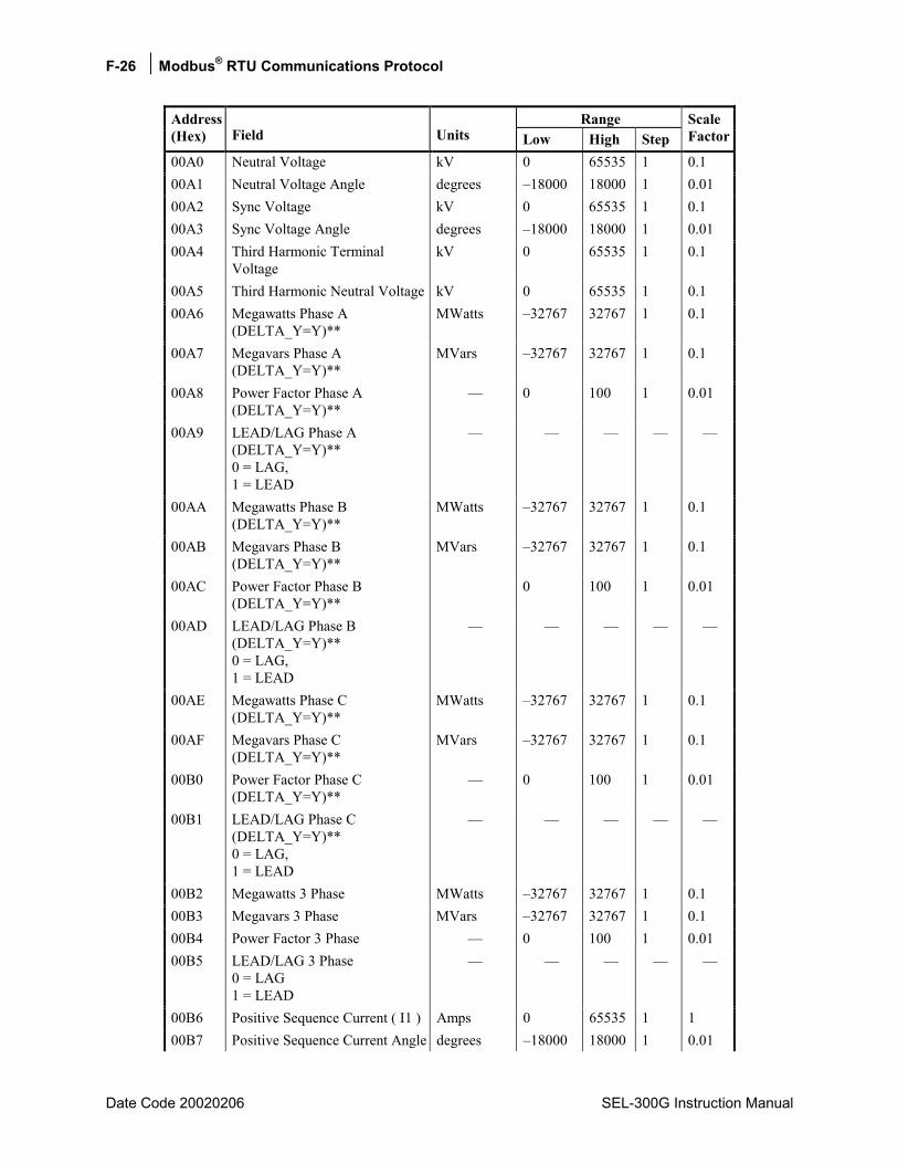
F-26 Modbus® RTU Communications Protocol
Date Code 20020206 SEL-300G Instruction Manual
Range Address (Hex) Field Units Low High Step
Scale Factor
00A0 Neutral Voltage kV 0 65535 1 0.1 00A1 Neutral Voltage Angle degrees 18000 18000 1 0.01 00A2 Sync Voltage kV 0 65535 1 0.1 00A3 Sync Voltage Angle degrees 18000 18000 1 0.01 00A4 Third Harmonic Terminal
Voltage kV 0 65535 1 0.1
00A5 Third Harmonic Neutral Voltage kV 0 65535 1 0.1 00A6 Megawatts Phase A
(DELTA_Y=Y)** MWatts 32767 32767 1 0.1
00A7 Megavars Phase A (DELTA_Y=Y)**
MVars 32767 32767 1 0.1
00A8 Power Factor Phase A (DELTA_Y=Y)**
0 100 1 0.01
00A9 LEAD/LAG Phase A (DELTA_Y=Y)** 0 = LAG, 1 = LEAD
00AA Megawatts Phase B (DELTA_Y=Y)**
MWatts 32767 32767 1 0.1
00AB Megavars Phase B (DELTA_Y=Y)**
MVars 32767 32767 1 0.1
00AC Power Factor Phase B (DELTA_Y=Y)**
0 100 1 0.01
00AD LEAD/LAG Phase B (DELTA_Y=Y)** 0 = LAG, 1 = LEAD
00AE Megawatts Phase C (DELTA_Y=Y)**
MWatts 32767 32767 1 0.1
00AF Megavars Phase C (DELTA_Y=Y)**
MVars 32767 32767 1 0.1
00B0 Power Factor Phase C (DELTA_Y=Y)**
0 100 1 0.01
00B1 LEAD/LAG Phase C (DELTA_Y=Y)** 0 = LAG, 1 = LEAD
00B2 Megawatts 3 Phase MWatts 32767 32767 1 0.1 00B3 Megavars 3 Phase MVars 32767 32767 1 0.1 00B4 Power Factor 3 Phase 0 100 1 0.01 00B5 LEAD/LAG 3 Phase
0 = LAG 1 = LEAD
00B6 Positive Sequence Current ( I1 ) Amps 0 65535 1 1 00B7 Positive Sequence Current Angle degrees 18000 18000 1 0.01

Modbus® RTU Communications Protocol F-27
SEL-300G Instruction Manual Date Code 20020206
Range Address (Hex) Field Units Low High Step
Scale Factor
00B8 Negative Sequence Current (3I2) Amps 0 65535 1 1 00B9 Negative Sequence Current
Angle degrees 18000 18000 1 0.01
00BA Zero Sequence Current (3I0) Amps 0 65535 1 1 00BB Zero Sequence Current Angle degrees 18000 18000 1 0.01 00BC Positive SequenceVoltage (V1) kV 0 65535 1 0.1 00BD Positive SequenceVoltage Angle degrees 18000 18000 1 0.01 00BE Negative SequenceVoltage (V2) kV 0 65535 1 0.1 00BF Negative SequenceVoltage
Angle degrees 18000 18000 1 0.01
00C0 Zero SequenceVoltage (3V0) kV 0 65535 1 0.1 00C1 Zero SequenceVoltage Angle degrees 18000 18000 1 0.01 00C2 Phase IA87 Current Amps 0 65535 1 1 00C3 Phase IA87 Current Angle degrees 18000 18000 1 0.01 00C4 Phase IB87 Current Amps 0 65535 1 1 00C5 Phase IB87 Current Angle degrees 18000 18000 1 0.01 00C6 Phase IC87 Current Amps 0 65535 1 1 00C7 Phase IC87 Current Angle degrees 18000 18000 1 0.01 00C8 Frequency Hertz 0 65535 1 0.01 00C9 DC Voltage V 0 65535 1 0.1 00CA Volts/Hertz % 65535 0.01 Differential Currents 00CB Operate current for winding 1 Amps 0 65535 1 0.01 00CC Restraint current for winding 1 Amps 0 65535 1 0.01 00CD Percent of restraint for
winding 1 0 65535 1 0.1
00CE Operate current for winding 2 Amps 0 65535 1 0.01 00CF Restraint current for winding 2 Amps 0 65535 1 0.01 00D0 Percent of restraint for
winding 2 0 65535 1 0.1
00D1 Operate current for winding 3 Amps 0 65535 1 0.01 00D2 Restraint current for winding 3 Amps 0 65535 1 0.01 00D3 Percent of restraint for
winding 3 0 65535 1 0.1
00D4 Second harmonic current in winding 1
Amps 0 65535 1 0.01
00D5 Percent of operate quantity for winding 1
0 65535 1 0.1
00D6 Second harmonic current in winding 2
Amps 0 65535 1 0.01

F-28 Modbus® RTU Communications Protocol
Date Code 20020206 SEL-300G Instruction Manual
Range Address (Hex) Field Units Low High Step
Scale Factor
00D7 Percent of operate quantity for winding 2
0 65535 1 0.1
00D8 Second harmonic current in winding 3
Amps 0 65535 1 0.01
00D9 Percent of operate quantity for winding 3
0 65535 1 0.1
Demand 00DA Demand Current Phase A Amps 0 65535 1 1 00DB Demand Current Phase B Amps 0 65535 1 1 00DC Demand Current Phase C Amps 0 65535 1 1 00DD Demand Neutral Current IN Amps 0 65535 1 1 00DE Demand Residual Current IG Amps 0 65535 1 1 00DF Demand Negative Sequence
Current 3I2 Amps 0 65535 1 1
Demand In 00E0 Megawatts Phase A
(DELTA_Y=Y)** MWatts 32767 32767 1 0.1
00E1 Megawatts Phase B (DELTA_Y=Y)**
MWatts 32767 32767 1 0.1
00E2 Megawatts Phase C (DELTA_Y=Y)**
MWatts 32767 32767 1 0.1
00E3 Megawatts 3 Phase MWatts 32767 32767 1 0.1 00E4 Megavars Phase A
(DELTA_Y=Y)** MVars 32767 32767 1 0.1
00E5 Megavars Phase B (DELTA_Y=Y)**
MVars 32767 32767 1 0.1
00E6 Megavars Phase C (DELTA_Y=Y)**
MVars 32767 32767 1 0.1
00E7 Megavars 3 Phase MVars 32767 32767 1 0.1 Demand Out 00E8 Megawatts Phase A
(DELTA_Y=Y)** MWatts 32767 32767 1 0.1
00E9 Megawatts Phase B (DELTA_Y=Y)**
MWatts 32767 32767 1 0.1
00EA Megawatts Phase C (DELTA_Y=Y)**
MWatts 32767 32767 1 0.1
00EB Megawatts 3 Phase MWatts 32767 32767 1 0.1 00EC Megavars Phase A
(DELTA_Y=Y)** MVars 32767 32767 1 0.1
00ED Megavars Phase B (DELTA_Y=Y)**
MVars 32767 32767 1 0.1
00EE Megavars Phase C (DELTA_Y=Y)**
MVars 32767 32767 1 0.1
00EF Megavars 3 Phase MVars 32767 32767 1 0.1
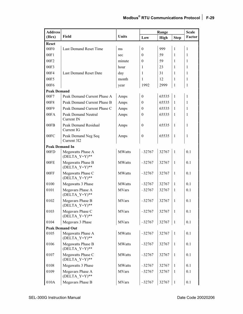
Modbus® RTU Communications Protocol F-29
SEL-300G Instruction Manual Date Code 20020206
Range Address (Hex) Field Units Low High Step
Scale Factor
Reset 00F0 Last Demand Reset Time ms 0 999 1 1 00F1 sec 0 59 1 1 00F2 minute 0 59 1 1 00F3 hour 1 23 1 1 00F4 Last Demand Reset Date day 1 31 1 1 00F5 month 1 12 1 1 00F6 year 1992 2999 1 1 Peak Demand 00F7 Peak Demand Current Phase A Amps 0 65535 1 1 00F8 Peak Demand Current Phase B Amps 0 65535 1 1 00F9 Peak Demand Current Phase C Amps 0 65535 1 1 00FA Peak Demand Neutral
Current IN Amps 0 65535 1 1
00FB Peak Demand Residual Current IG
Amps 0 65535 1 1
00FC Peak Demand Neg Seq Current 3I2
Amps 0 65535 1 1
Peak Demand In 00FD Megawatts Phase A
(DELTA_Y=Y)** MWatts 32767 32767 1 0.1
00FE Megawatts Phase B (DELTA_Y=Y)**
MWatts 32767 32767 1 0.1
00FF Megawatts Phase C (DELTA_Y=Y)**
MWatts 32767 32767 1 0.1
0100 Megawatts 3 Phase MWatts 32767 32767 1 0.1 0101 Megavars Phase A
(DELTA_Y=Y)** MVars 32767 32767 1 0.1
0102 Megavars Phase B (DELTA_Y=Y)**
MVars 32767 32767 1 0.1
0103 Megavars Phase C (DELTA_Y=Y)**
MVars 32767 32767 1 0.1
0104 Megavars 3 Phase MVars 32767 32767 1 0.1 Peak Demand Out 0105 Megawatts Phase A
(DELTA_Y=Y)** MWatts 32767 32767 1 0.1
0106 Megawatts Phase B (DELTA_Y=Y)**
MWatts 32767 32767 1 0.1
0107 Megawatts Phase C (DELTA_Y=Y)**
MWatts 32767 32767 1 0.1
0108 Megawatts 3 Phase MWatts 32767 32767 1 0.1 0109 Megavars Phase A
(DELTA_Y=Y)** MVars 32767 32767 1 0.1
010A Megavars Phase B MVars 32767 32767 1 0.1
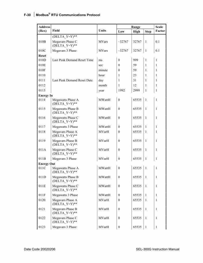
F-30 Modbus® RTU Communications Protocol
Date Code 20020206 SEL-300G Instruction Manual
Range Address (Hex) Field Units Low High Step
Scale Factor
(DELTA_Y=Y)** 010B Megavars Phase C
(DELTA_Y=Y)** MVars 32767 32767 1 0.1
010C Megavars 3 Phase MVars 32767 32767 1 0.1 Reset 010D Last Peak Demand Reset Time ms 0 999 1 1 010E sec 0 59 1 1 010F minute 0 59 1 1 0110 hour 1 23 1 1 0111 Last Peak Demand Reset Date day 1 31 1 1 0112 month 1 12 1 1 0113 year 1992 2999 1 1 Energy In 0114 Megawatts Phase A
(DELTA_Y=Y)** MWattH 0 65535 1 1
0115 Megawatts Phase B (DELTA_Y=Y)**
MWattH 0 65535 1 1
0116 Megawatts Phase C (DELTA_Y=Y)**
MWattH 0 65535 1 1
0117 Megawatts 3 Phase MWattH 0 65535 1 1 0118 Megavars Phase A
(DELTA_Y=Y)** MVarH 0 65535 1 1
0119 Megavars Phase B (DELTA_Y=Y)**
MVarH 0 65535 1 1
011A Megavars Phase C (DELTA_Y=Y)**
MVarH 0 65535 1 1
011B Megavars 3 Phase MVarH 0 65535 1 1 Energy Out 011C Megawatts Phase A
(DELTA_Y=Y)** MWattH 0 65535 1 1
011D Megawatts Phase B (DELTA_Y=Y)**
MWattH 0 65535 1 1
011E Megawatts Phase C (DELTA_Y=Y)**
MWattH 0 65535 1 1
011F Megawatts 3 Phase MWattH 0 65535 1 1 0120 Megavars Phase A
(DELTA_Y=Y)** MVarH 0 65535 1 1
0121 Megavars Phase B (DELTA_Y=Y)**
MVarH 0 65535 1 1
0122 Megavars Phase C (DELTA_Y=Y)**
MVarH 0 65535 1 1
0123 Megavars 3 Phase MVarH 0 65535 1 1
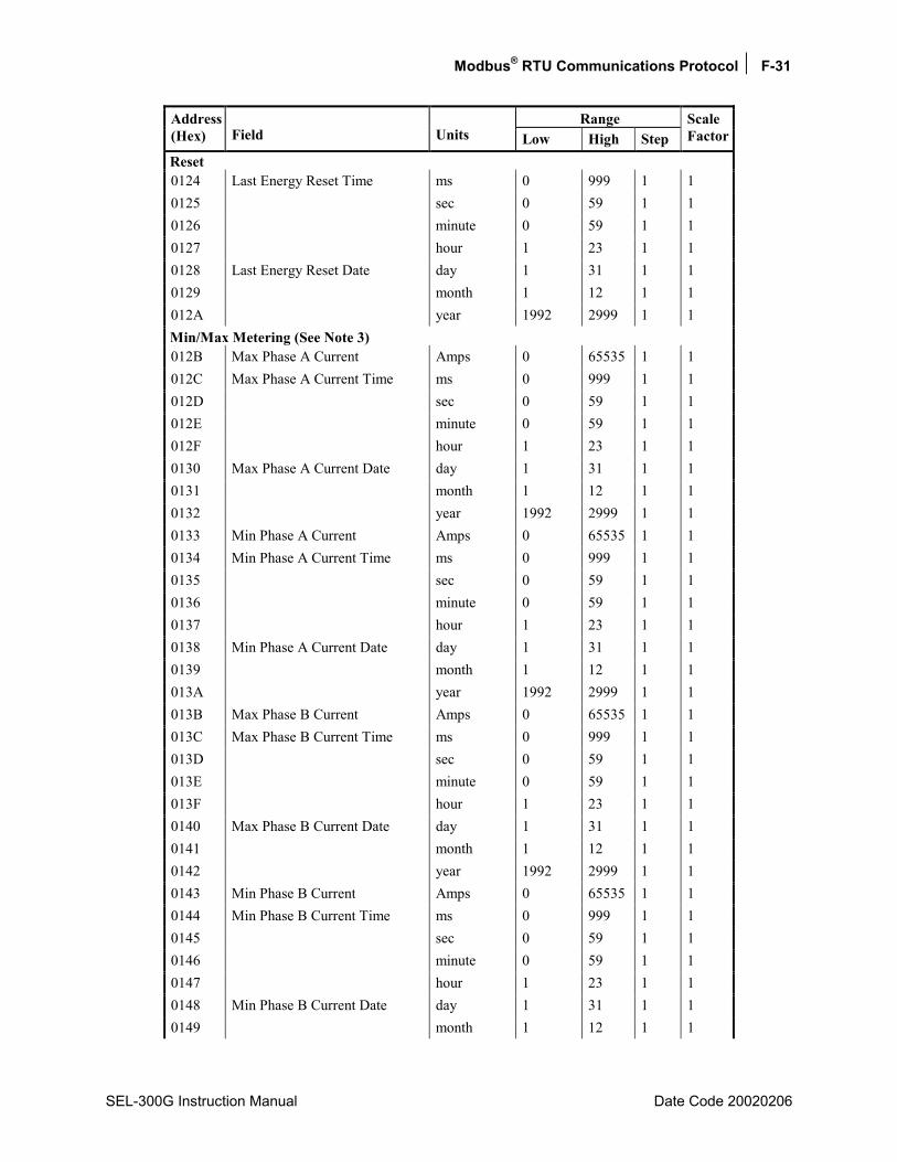
Modbus® RTU Communications Protocol F-31
SEL-300G Instruction Manual Date Code 20020206
Range Address (Hex) Field Units Low High Step
Scale Factor
Reset 0124 Last Energy Reset Time ms 0 999 1 1 0125 sec 0 59 1 1 0126 minute 0 59 1 1 0127 hour 1 23 1 1 0128 Last Energy Reset Date day 1 31 1 1 0129 month 1 12 1 1 012A year 1992 2999 1 1 Min/Max Metering (See Note 3) 012B Max Phase A Current Amps 0 65535 1 1 012C Max Phase A Current Time ms 0 999 1 1 012D sec 0 59 1 1 012E minute 0 59 1 1 012F hour 1 23 1 1 0130 Max Phase A Current Date day 1 31 1 1 0131 month 1 12 1 1 0132 year 1992 2999 1 1 0133 Min Phase A Current Amps 0 65535 1 1 0134 Min Phase A Current Time ms 0 999 1 1 0135 sec 0 59 1 1 0136 minute 0 59 1 1 0137 hour 1 23 1 1 0138 Min Phase A Current Date day 1 31 1 1 0139 month 1 12 1 1 013A year 1992 2999 1 1 013B Max Phase B Current Amps 0 65535 1 1 013C Max Phase B Current Time ms 0 999 1 1 013D sec 0 59 1 1 013E minute 0 59 1 1 013F hour 1 23 1 1 0140 Max Phase B Current Date day 1 31 1 1 0141 month 1 12 1 1 0142 year 1992 2999 1 1 0143 Min Phase B Current Amps 0 65535 1 1 0144 Min Phase B Current Time ms 0 999 1 1 0145 sec 0 59 1 1 0146 minute 0 59 1 1 0147 hour 1 23 1 1 0148 Min Phase B Current Date day 1 31 1 1 0149 month 1 12 1 1
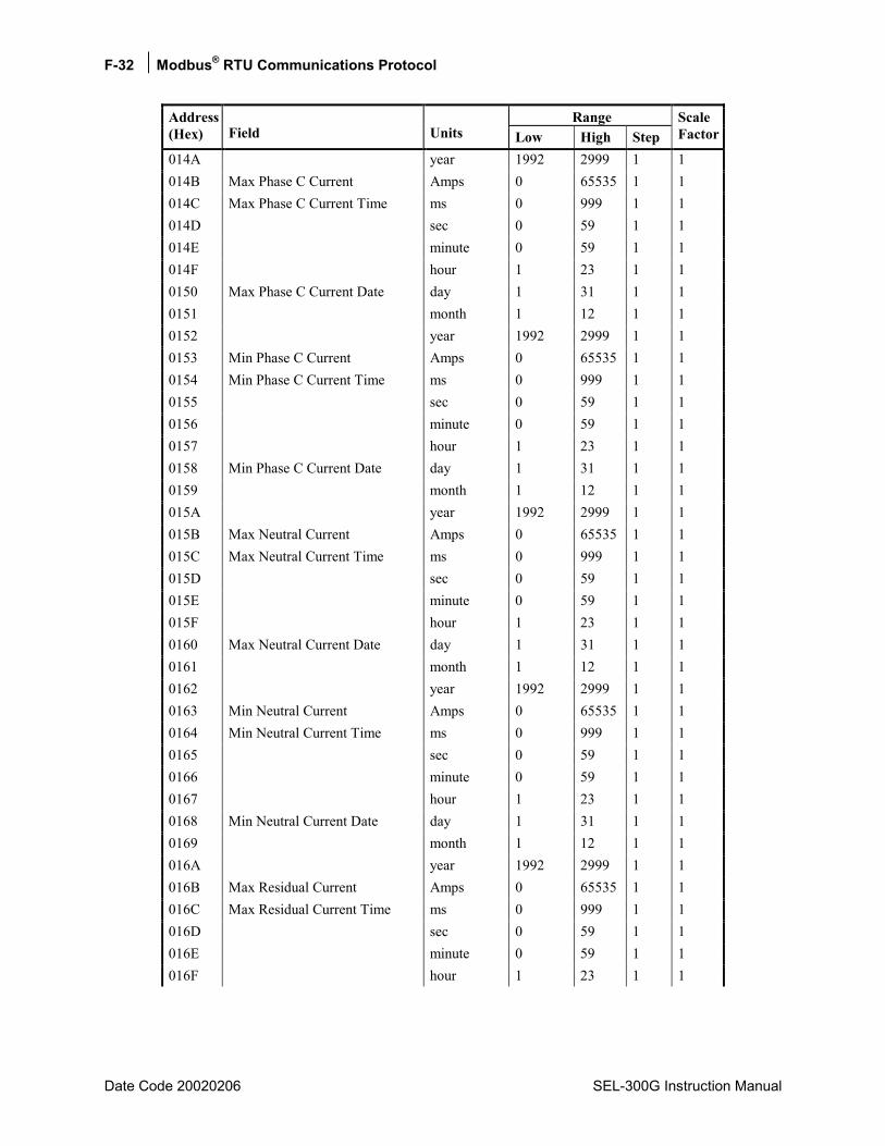
F-32 Modbus® RTU Communications Protocol
Date Code 20020206 SEL-300G Instruction Manual
Range Address (Hex) Field Units Low High Step
Scale Factor
014A year 1992 2999 1 1 014B Max Phase C Current Amps 0 65535 1 1 014C Max Phase C Current Time ms 0 999 1 1 014D sec 0 59 1 1 014E minute 0 59 1 1 014F hour 1 23 1 1 0150 Max Phase C Current Date day 1 31 1 1 0151 month 1 12 1 1 0152 year 1992 2999 1 1 0153 Min Phase C Current Amps 0 65535 1 1 0154 Min Phase C Current Time ms 0 999 1 1 0155 sec 0 59 1 1 0156 minute 0 59 1 1 0157 hour 1 23 1 1 0158 Min Phase C Current Date day 1 31 1 1 0159 month 1 12 1 1 015A year 1992 2999 1 1 015B Max Neutral Current Amps 0 65535 1 1 015C Max Neutral Current Time ms 0 999 1 1 015D sec 0 59 1 1 015E minute 0 59 1 1 015F hour 1 23 1 1 0160 Max Neutral Current Date day 1 31 1 1 0161 month 1 12 1 1 0162 year 1992 2999 1 1 0163 Min Neutral Current Amps 0 65535 1 1 0164 Min Neutral Current Time ms 0 999 1 1 0165 sec 0 59 1 1 0166 minute 0 59 1 1 0167 hour 1 23 1 1 0168 Min Neutral Current Date day 1 31 1 1 0169 month 1 12 1 1 016A year 1992 2999 1 1 016B Max Residual Current Amps 0 65535 1 1 016C Max Residual Current Time ms 0 999 1 1 016D sec 0 59 1 1 016E minute 0 59 1 1 016F hour 1 23 1 1

Modbus® RTU Communications Protocol F-33
SEL-300G Instruction Manual Date Code 20020206
Range Address (Hex) Field Units Low High Step
Scale Factor
0170 Max Residual Current Date day 1 31 1 1 0171 month 1 12 1 1 0172 year 1992 2999 1 1 0173 Min Residual Current Amps 0 65535 1 1 0174 Min Residual Current Time ms 0 999 1 1 0175 sec 0 59 1 1 0176 minute 0 59 1 1 0177 hour 1 23 1 1 0178 Min Residual Current Date day 1 31 1 1 0179 month 1 12 1 1 017A year 1992 2999 1 1 017B Max Phase A Voltage kV 0 65535 1 0.1 017C Max Phase A Voltage Time ms 0 999 1 1 017D sec 0 59 1 1 017E minute 0 59 1 1 017F hour 1 23 1 1 0180 Max Phase A Voltage Date day 1 31 1 1 0181 month 1 12 1 1 0182 year 1992 2999 1 1 0183 Min Phase A Voltage kV 0 65535 1 0.1 0184 Min Phase A Voltage Time ms 0 999 1 1 0185 sec 0 59 1 1 0186 minute 0 59 1 1 0187 hour 1 23 1 1 0188 Min Phase A Voltage Date day 1 31 1 1 0189 month 1 12 1 1 018A year 1992 2999 1 1 018B Max Phase B Voltage kV 0 65535 1 0.1 018C Max Phase B Voltage Time ms 0 999 1 1 018D sec 0 59 1 1 018E minute 0 59 1 1 018F hour 1 23 1 1 0190 Max Phase B Voltage Date day 1 31 1 1 0191 month 1 12 1 1 0192 year 1992 2999 1 1 0193 Min Phase B Voltage kV 0 65535 1 0.1 0194 Min Phase B Voltage Time ms 0 999 1 1 0195 sec 0 59 1 1 0196 minute 0 59 1 1 0197 hour 1 23 1 1

F-34 Modbus® RTU Communications Protocol
Date Code 20020206 SEL-300G Instruction Manual
Range Address (Hex) Field Units Low High Step
Scale Factor
0198 Min Phase B Voltage Date day 1 31 1 1 0199 month 1 12 1 1 019A year 1992 2999 1 1 019B Max Phase C Voltage kV 0 65535 1 0.1 019C Max Phase C Voltage Time ms 0 999 1 1 019D sec 0 59 1 1 019E minute 0 59 1 1 019F hour 1 23 1 1 01A0 Max Phase C Voltage Date day 1 31 1 1 01A1 month 1 12 1 1 01A2 year 1992 2999 1 1 01A3 Min Phase C Voltage kV 0 65535 1 0.1 01A4 Min Phase C Voltage Time ms 0 999 1 1 01A5 sec 0 59 1 1 01A6 minute 0 59 1 1 01A7 hour 1 23 1 1 01A8 Min Phase C Voltage Date day 1 31 1 1 01A9 month 1 12 1 1 01AA year 1992 2999 1 1 01AB Max Sync Voltage kV 0 65535 1 0.1 01AC Max Sync Voltage Time ms 0 999 1 1 01AD sec 0 59 1 1 01AE minute 0 59 1 1 01AF hour 1 23 1 1 01B0 Max Sync Voltage Date day 1 31 1 1 01B1 month 1 12 1 1 01B2 year 1992 2999 1 1 01B3 Min Sync Voltage kV 0 65535 1 0.1 01B4 Min Sync Voltage Time ms 0 999 1 1 01B5 sec 0 59 1 1 01B6 minute 0 59 1 1 01B7 hour 1 23 1 1 01B8 Min Sync Voltage Date day 1 31 1 1 01B9 month 1 12 1 1 01BA year 1992 2999 1 1 01BB Max Neutral Voltage kV 0 65535 1 0.1 01BC Max Neutral Voltage Time ms 0 999 1 1 01BD sec 0 59 1 1 01BE minute 0 59 1 1 01BF hour 1 23 1 1
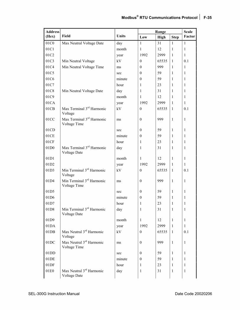
Modbus® RTU Communications Protocol F-35
SEL-300G Instruction Manual Date Code 20020206
Range Address (Hex) Field Units Low High Step
Scale Factor
01C0 Max Neutral Voltage Date day 1 31 1 1 01C1 month 1 12 1 1 01C2 year 1992 2999 1 1 01C3 Min Neutral Voltage kV 0 65535 1 0.1 01C4 Min Neutral Voltage Time ms 0 999 1 1 01C5 sec 0 59 1 1 01C6 minute 0 59 1 1 01C7 hour 1 23 1 1 01C8 Min Neutral Voltage Date day 1 31 1 1 01C9 month 1 12 1 1 01CA year 1992 2999 1 1 01CB Max Terminal 3rd Harmonic
Voltage kV 0 65535 1 0.1
01CC Max Terminal 3rd Harmonic Voltage Time
ms 0 999 1 1
01CD sec 0 59 1 1 01CE minute 0 59 1 1 01CF hour 1 23 1 1 01D0 Max Terminal 3rd Harmonic
Voltage Date day 1 31 1 1
01D1 month 1 12 1 1 01D2 year 1992 2999 1 1 01D3 Min Terminal 3rd Harmonic
Voltage kV 0 65535 1 0.1
01D4 Min Terminal 3rd Harmonic Voltage Time
ms 0 999 1 1
01D5 sec 0 59 1 1 01D6 minute 0 59 1 1 01D7 hour 1 23 1 1 01D8 Min Terminal 3rd Harmonic
Voltage Date day 1 31 1 1
01D9 month 1 12 1 1 01DA year 1992 2999 1 1 01DB Max Neutral 3rd Harmonic
Voltage kV 0 65535 1 0.1
01DC Max Neutral 3rd Harmonic Voltage Time
ms 0 999 1 1
01DD sec 0 59 1 1 01DE minute 0 59 1 1 01DF hour 1 23 1 1 01E0 Max Neutral 3rd Harmonic
Voltage Date day 1 31 1 1
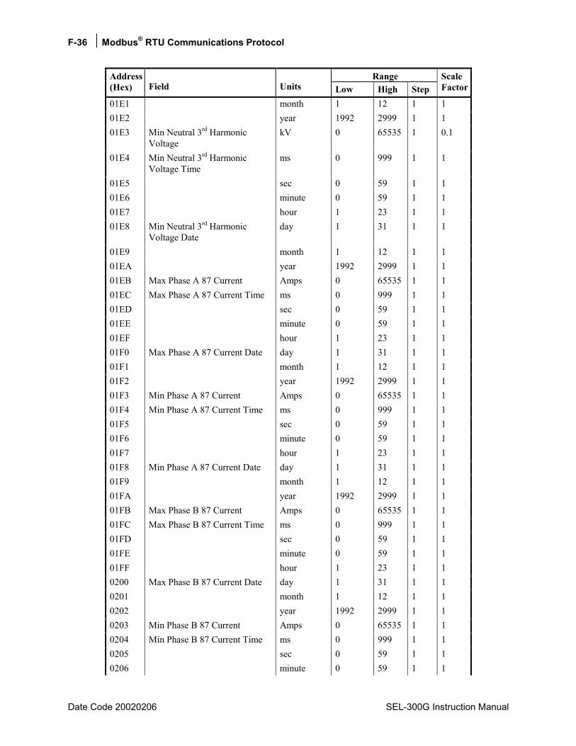
F-36 Modbus® RTU Communications Protocol
Date Code 20020206 SEL-300G Instruction Manual
Range Address (Hex) Field Units Low High Step
Scale Factor
01E1 month 1 12 1 1 01E2 year 1992 2999 1 1 01E3 Min Neutral 3rd Harmonic
Voltage kV 0 65535 1 0.1
01E4 Min Neutral 3rd Harmonic Voltage Time
ms 0 999 1 1
01E5 sec 0 59 1 1 01E6 minute 0 59 1 1 01E7 hour 1 23 1 1 01E8 Min Neutral 3rd Harmonic
Voltage Date day 1 31 1 1
01E9 month 1 12 1 1 01EA year 1992 2999 1 1 01EB Max Phase A 87 Current Amps 0 65535 1 1 01EC Max Phase A 87 Current Time ms 0 999 1 1 01ED sec 0 59 1 1 01EE minute 0 59 1 1 01EF hour 1 23 1 1 01F0 Max Phase A 87 Current Date day 1 31 1 1 01F1 month 1 12 1 1 01F2 year 1992 2999 1 1 01F3 Min Phase A 87 Current Amps 0 65535 1 1 01F4 Min Phase A 87 Current Time ms 0 999 1 1 01F5 sec 0 59 1 1 01F6 minute 0 59 1 1 01F7 hour 1 23 1 1 01F8 Min Phase A 87 Current Date day 1 31 1 1 01F9 month 1 12 1 1 01FA year 1992 2999 1 1 01FB Max Phase B 87 Current Amps 0 65535 1 1 01FC Max Phase B 87 Current Time ms 0 999 1 1 01FD sec 0 59 1 1 01FE minute 0 59 1 1 01FF hour 1 23 1 1 0200 Max Phase B 87 Current Date day 1 31 1 1 0201 month 1 12 1 1 0202 year 1992 2999 1 1 0203 Min Phase B 87 Current Amps 0 65535 1 1 0204 Min Phase B 87 Current Time ms 0 999 1 1 0205 sec 0 59 1 1 0206 minute 0 59 1 1

Modbus® RTU Communications Protocol F-37
SEL-300G Instruction Manual Date Code 20020206
Range Address (Hex) Field Units Low High Step
Scale Factor
0207 hour 1 23 1 1 0208 Min Phase B 87 Current Date day 1 31 1 1 0209 month 1 12 1 1 020A year 1992 2999 1 1 020B Max Phase C 87 Current Amps 0 65535 1 1 020C Max Phase C 87 Current Time ms 0 999 1 1 020D sec 0 59 1 1 020E minute 0 59 1 1 020F hour 1 23 1 1 0210 Max Phase C 87 Current Date day 1 31 1 1 0211 month 1 12 1 1 0212 year 1992 2999 1 1 0213 Min Phase C 87 Current Amps 0 65535 1 1 0214 Min Phase C 87 Current Time ms 0 999 1 1 0215 sec 0 59 1 1 0216 minute 0 59 1 1 0217 hour 1 23 1 1 0218 Min Phase C 87 Current Date day 1 31 1 1 0219 month 1 12 1 1 021A year 1992 2999 1 1 021B Max 3 Phase Mega Watts MWatts 32767 32767 1 0.1 021C Max 3 Phase Mega Watts Time ms 0 999 1 1 021D sec 0 59 1 1 021E minute 0 59 1 1 021F hour 1 23 1 1 0220 Max 3 Phase Mega Watts Date day 1 31 1 1 0221 month 1 12 1 1 0222 year 1992 2999 1 1 0223 Min 3 Phase Mega Watts MWatts 32767 32767 1 0.1 0224 Min 3 Phase Mega Watts Time ms 0 999 1 1 0225 sec 0 59 1 1 0226 minute 0 59 1 1 0227 hour 1 23 1 1 0228 Min 3 Phase Mega Watts Date day 1 31 1 1 0229 month 1 12 1 1 022A year 1992 2999 1 1 022B Max 3 Phase Mega Vars MVars 32767 32767 1 0.1 022C Max 3 Phase Mega Vars Time ms 0 999 1 1 022D sec 0 59 1 1 022E minute 0 59 1 1

F-38 Modbus® RTU Communications Protocol
Date Code 20020206 SEL-300G Instruction Manual
Range Address (Hex) Field Units Low High Step
Scale Factor
022F hour 1 23 1 1 0230 Max 3 Phase Mega Vars Date day 1 31 1 1 0231 month 1 12 1 1 0232 year 1992 2999 1 1 0233 Min 3 Phase Mega Vars MVars 32767 32767 1 0.1 0234 Min 3 Phase Mega Vars Time ms 0 999 1 1 0235 sec 0 59 1 1 0236 minute 0 59 1 1 0237 hour 1 23 1 1 0238 Min 3 Phase Mega Vars Date day 1 31 1 1 0239 month 1 12 1 1 023A year 1992 2999 1 1 023B Last Reset Time ms 0 999 1 1 023C sec 0 59 1 1 023D minute 0 59 1 1 023E hour 1 23 1 1 023F Last Reset Date day 1 31 1 1 0240 month 1 12 1 1 0241 year 1992 2999 1 1 Thermal Metering 0242 Temp Input 1 degrees
(see Note 4) 32767 32767 1 1
0243 Temp Input 2 degrees 32767 32767 1 1 0244 Temp Input 3 degrees 32767 32767 1 1 0245 Temp Input 4 degrees 32767 32767 1 1 0246 Temp Input 5 degrees 32767 32767 1 1 0247 Temp Input 6 degrees 32767 32767 1 1 0248 Temp Input 7 degrees 32767 32767 1 1 0249 Temp Input 8 degrees 32767 32767 1 1 024A Temp Input 9 degrees 32767 32767 1 1 024B Temp Input 10 degrees 32767 32767 1 1 024C Temp Input 11 degrees 32767 32767 1 1 024D Temp Input 12 degrees 32767 32767 1 1 024E Reserved 024F Reserved Relay Time and Date 0250 Time ss (RW)
(See Note 5)0 59 1 1
0251 minute (RW) 0 59 1 1 0252 hour (RW) 1 23 1 1 0253 Date day (RW) 1 31 1 1
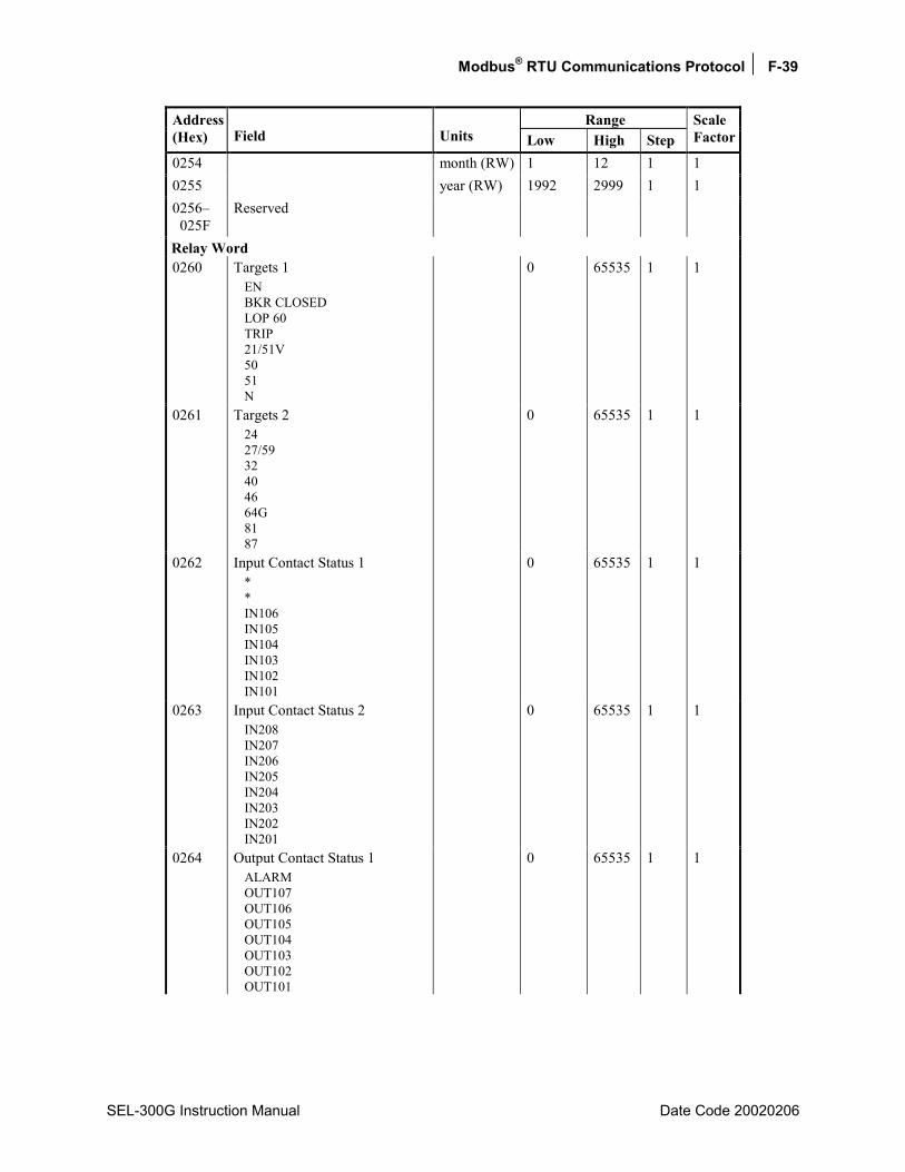
Modbus® RTU Communications Protocol F-39
SEL-300G Instruction Manual Date Code 20020206
Range Address (Hex) Field Units Low High Step
Scale Factor
0254 month (RW) 1 12 1 1 0255 year (RW) 1992 2999 1 1 0256 025F
Reserved
Relay Word 0260 Targets 1
EN BKR CLOSED LOP 60 TRIP 21/51V 50 51 N
0 65535 1 1
0261 Targets 2 24 27/59 32 40 46 64G 81 87
0 65535 1 1
0262 Input Contact Status 1 * * IN106 IN105 IN104 IN103 IN102 IN101
0 65535 1 1
0263 Input Contact Status 2 IN208 IN207 IN206 IN205 IN204 IN203 IN202 IN201
0 65535 1 1
0264 Output Contact Status 1 ALARM OUT107 OUT106 OUT105 OUT104 OUT103 OUT102 OUT101
0 65535 1 1
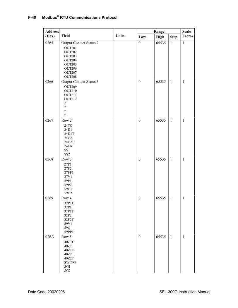
F-40 Modbus® RTU Communications Protocol
Date Code 20020206 SEL-300G Instruction Manual
Range Address (Hex) Field Units Low High Step
Scale Factor
0265 Output Contact Status 2 OUT201 OUT202 OUT203 OUT204 OUT205 OUT206 OUT207 OUT208
0 65535 1 1
0266 Output Contact Status 3 OUT209 OUT210 OUT211 OUT212 * * * *
0 65535 1 1
0267 Row 2 24TC 24D1 24D1T 24C2 24C2T 24CR SS1 SS2
0 65535 1 1
0268 Row 3 27P1 27P2 27PP1 27V1 59P1 59P2 59G1 59G2
0 65535 1 1
0269 Row 4 32PTC 32P1 32P1T 32P2 32P2T 59V1 59Q 59PP1
0 65535 1 1
026A Row 5 40ZTC 40Z1 40Z1T 40Z2 40Z2T SWING SG1 SG2
0 65535 1 1
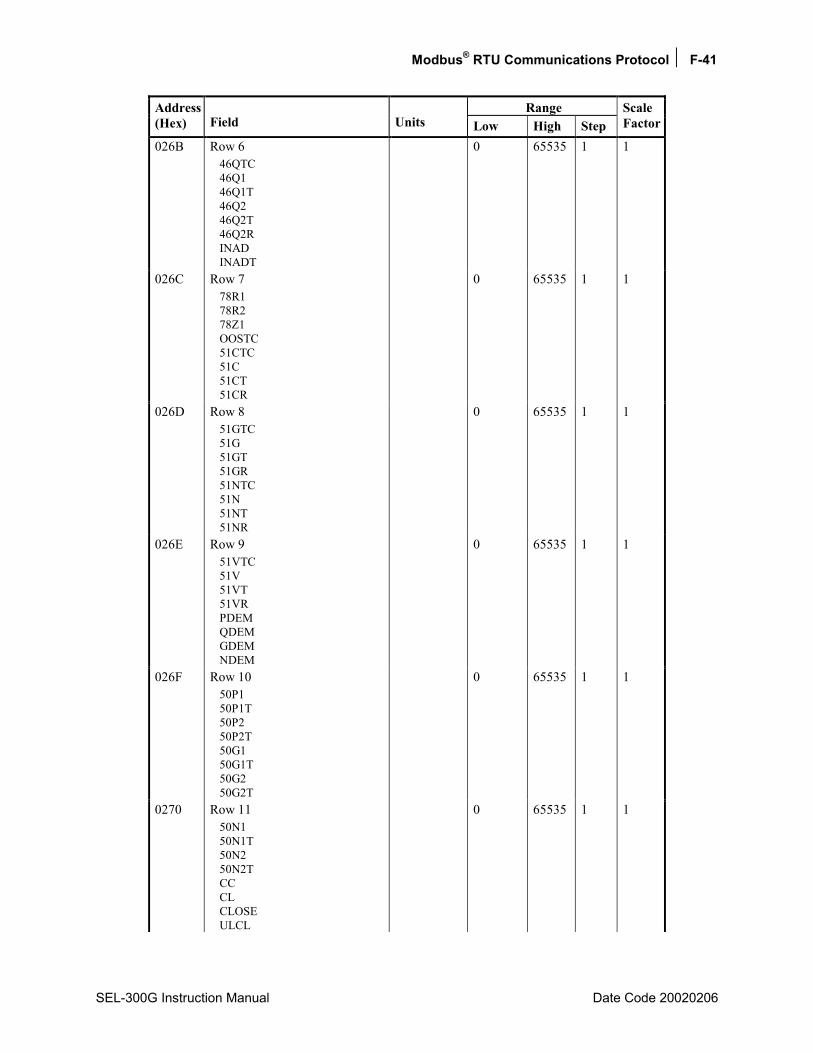
Modbus® RTU Communications Protocol F-41
SEL-300G Instruction Manual Date Code 20020206
Range Address (Hex) Field Units Low High Step
Scale Factor
026B Row 6 46QTC 46Q1 46Q1T 46Q2 46Q2T 46Q2R INAD INADT
0 65535 1 1
026C Row 7 78R1 78R2 78Z1 OOSTC 51CTC 51C 51CT 51CR
0 65535 1 1
026D Row 8 51GTC 51G 51GT 51GR 51NTC 51N 51NT 51NR
0 65535 1 1
026E Row 9 51VTC 51V 51VT 51VR PDEM QDEM GDEM NDEM
0 65535 1 1
026F Row 10 50P1 50P1T 50P2 50P2T 50G1 50G1T 50G2 50G2T
0 65535 1 1
0270 Row 11 50N1 50N1T 50N2 50N2T CC CL CLOSE ULCL
0 65535 1 1
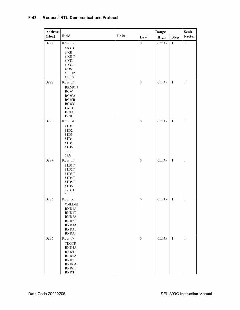
F-42 Modbus® RTU Communications Protocol
Date Code 20020206 SEL-300G Instruction Manual
Range Address (Hex) Field Units Low High Step
Scale Factor
0271 Row 12 64GTC 64G1 64G1T 64G2 64G2T OOS 60LOP CLEN
0 65535 1 1
0272 Row 13 BKMON BCW BCWA BCWB BCWC FAULT DCLO DCHI
0 65535 1 1
0273 Row 14 81D1 81D2 81D3 81D4 81D5 81D6 3PO 52A
0 65535 1 1
0274 Row 15 81D1T 81D2T 81D3T 81D4T 81D5T 81D6T 27B81 50L
0 65535 1 1
0275 Row 16 ONLINE BND1A BND1T BND2A BND2T BND3A BND3T BNDA
0 65535 1 1
0276 Row 17 TRGTR BND4A BND4T BND5A BND5T BND6A BND6T BNDT
0 65535 1 1
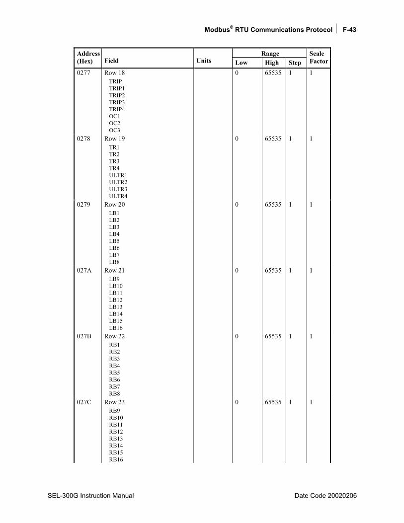
Modbus® RTU Communications Protocol F-43
SEL-300G Instruction Manual Date Code 20020206
Range Address (Hex) Field Units Low High Step
Scale Factor
0277 Row 18 TRIP TRIP1 TRIP2 TRIP3 TRIP4 OC1 OC2 OC3
0 65535 1 1
0278 Row 19 TR1 TR2 TR3 TR4 ULTR1 ULTR2 ULTR3 ULTR4
0 65535 1 1
0279 Row 20 LB1 LB2 LB3 LB4 LB5 LB6 LB7 LB8
0 65535 1 1
027A Row 21 LB9 LB10 LB11 LB12 LB13 LB14 LB15 LB16
0 65535 1 1
027B Row 22 RB1 RB2 RB3 RB4 RB5 RB6 RB7 RB8
0 65535 1 1
027C Row 23 RB9 RB10 RB11 RB12 RB13 RB14 RB15 RB16
0 65535 1 1
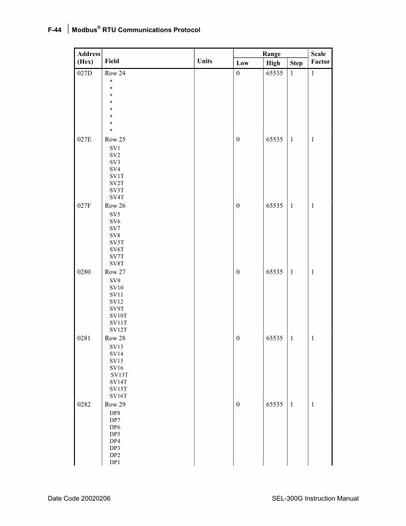
F-44 Modbus® RTU Communications Protocol
Date Code 20020206 SEL-300G Instruction Manual
Range Address (Hex) Field Units Low High Step
Scale Factor
027D Row 24 * * * * * * * *
0 65535 1 1
027E Row 25 SV1 SV2 SV3 SV4 SV1T SV2T SV3T SV4T
0 65535 1 1
027F Row 26 SV5 SV6 SV7 SV8 SV5T SV6T SV7T SV8T
0 65535 1 1
0280 Row 27 SV9 SV10 SV11 SV12 SV9T SV10T SV11T SV12T
0 65535 1 1
0281 Row 28 SV13 SV14 SV15 SV16 SV13T SV14T SV15T SV16T
0 65535 1 1
0282 Row 29 DP8 DP7 DP6 DP5 DP4 DP3 DP2 DP1
0 65535 1 1
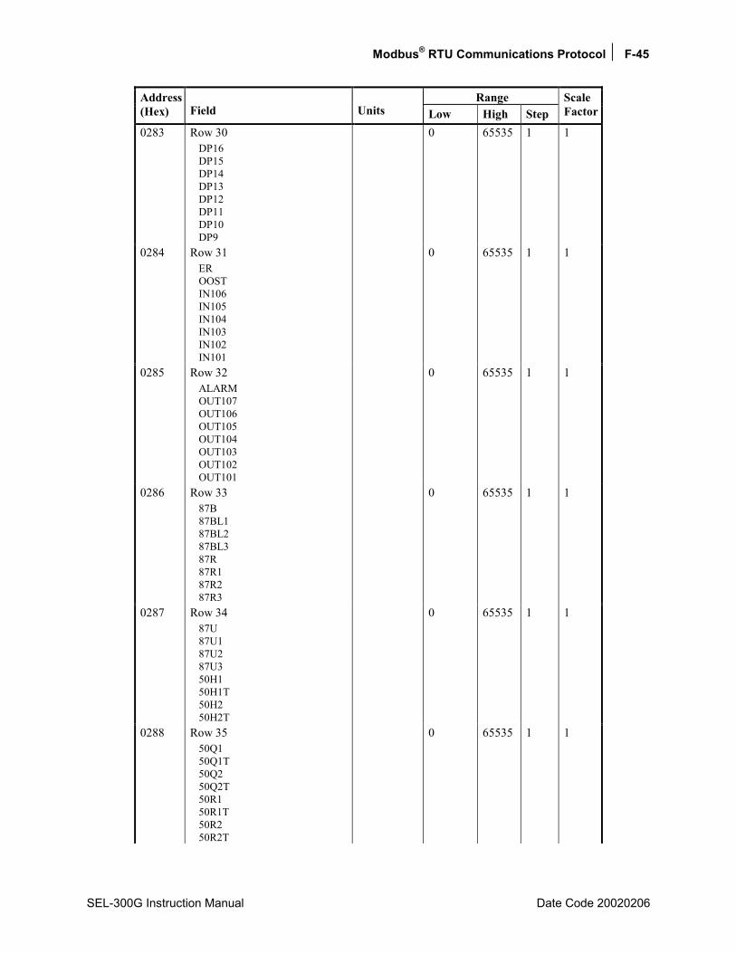
Modbus® RTU Communications Protocol F-45
SEL-300G Instruction Manual Date Code 20020206
Range Address (Hex) Field Units Low High Step
Scale Factor
0283 Row 30 DP16 DP15 DP14 DP13 DP12 DP11 DP10 DP9
0 65535 1 1
0284 Row 31 ER OOST IN106 IN105 IN104 IN103 IN102 IN101
0 65535 1 1
0285 Row 32 ALARM OUT107 OUT106 OUT105 OUT104 OUT103 OUT102 OUT101
0 65535 1 1
0286 Row 33 87B 87BL1 87BL2 87BL3 87R 87R1 87R2 87R3
0 65535 1 1
0287 Row 34 87U 87U1 87U2 87U3 50H1 50H1T 50H2 50H2T
0 65535 1 1
0288 Row 35 50Q1 50Q1T 50Q2 50Q2T 50R1 50R1T 50R2 50R2T
0 65535 1 1
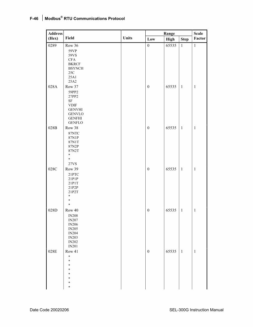
F-46 Modbus® RTU Communications Protocol
Date Code 20020206 SEL-300G Instruction Manual
Range Address (Hex) Field Units Low High Step
Scale Factor
0289 Row 36 59VP 59VS CFA BKRCF BSYNCH 25C 25A1 25A2
0 65535 1 1
028A Row 37 59PP2 27PP2 SF VDIF GENVHI GENVLO GENFHI GENFLO
0 65535 1 1
028B Row 38 87NTC 87N1P 87N1T 87N2P 87N2T * * 27VS
0 65535 1 1
028C Row 39 21PTC 21P1P 21P1T 21P2P 21P2T * * *
0 65535 1 1
028D Row 40 IN208 IN207 IN206 IN205 IN204 IN203 IN202 IN201
0 65535 1 1
028E Row 41 * * * * * * * *
0 65535 1 1

Modbus® RTU Communications Protocol F-47
SEL-300G Instruction Manual Date Code 20020206
Range Address (Hex) Field Units Low High Step
Scale Factor
028F Row 42 OUT201 OUT202 OUT203 OUT204 OUT205 OUT206 OUT207 OUT208
0 65535 1 1
0290 Row 43 OUT209 OUT210 OUT211 OUT212 * * * *
0 65535 1 1
0291 Row 44 50H2A 50H2B 50H2C * * * * *
0 65535 1 1
0292 Row 45 * * * * * * * *
0 65535 1 1
0293 Row 46 SET1 SET2 SET3 SET4 SET5 SET6 SET7 SET8
0 65535 1 1
0294 Row 47 SET9 SET10 SET11 SET12 SET13 SET14 SET15 SET16
0 65535 1 1

F-48 Modbus® RTU Communications Protocol
Date Code 20020206 SEL-300G Instruction Manual
Range Address (Hex) Field Units Low High Step
Scale Factor
0295 Row 48 RST1 RST2 RST3 RST4 RST5 RST6 RST7 RST8
0 65535 1 1
0296 Row 49 RST9 RST10 RST11 RST12 RST13 RST14 RST15 RST16
0 65535 1 1
0297 Row 50 LT1 LT2 LT3 LT4 LT5 LT6 LT7 LT8
0 65535 1 1
0298 Row 51 LT9 LT10 LT11 LT12 LT13 LT14 LT15 LT16
0 65535 1 1
0299 Row 52 OTHTRIPOTHALRM AMBTRIP AMBALRMBRGTRIP BRGALRMWDGTRIPWDGALRM
0 65535 1 1
029A Row 53 RTDFLT * * * * * * 2600IN
0 65535 1 1
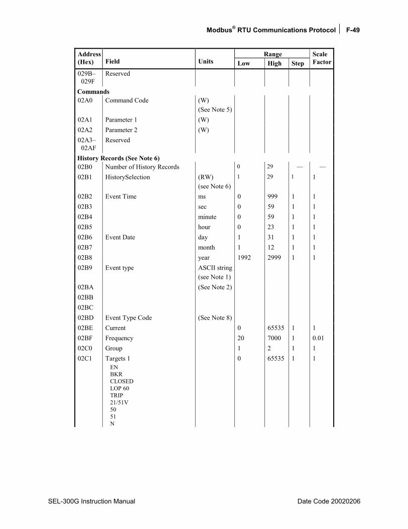
Modbus® RTU Communications Protocol F-49
SEL-300G Instruction Manual Date Code 20020206
Range Address (Hex) Field Units Low High Step
Scale Factor
029B 029F
Reserved
Commands 02A0 Command Code (W)
(See Note 5)
02A1 Parameter 1 (W) 02A2 Parameter 2 (W) 02A3 02AF
Reserved
History Records (See Note 6) 02B0 Number of History Records 0 29 02B1 HistorySelection (RW)
(see Note 6) 1 29 1 1
02B2 Event Time ms 0 999 1 1 02B3 sec 0 59 1 1 02B4 minute 0 59 1 1 02B5 hour 0 23 1 1 02B6 Event Date day 1 31 1 1 02B7 month 1 12 1 1 02B8 year 1992 2999 1 1 02B9 Event type ASCII string
(see Note 1)
02BA (See Note 2) 02BB 02BC 02BD Event Type Code (See Note 8) 02BE Current 0 65535 1 1 02BF Frequency 20 7000 1 0.01 02C0 Group 1 2 1 1 02C1 Targets 1
EN BKR CLOSED LOP 60 TRIP 21/51V 50 51 N
0 65535 1 1

F-50 Modbus® RTU Communications Protocol
Date Code 20020206 SEL-300G Instruction Manual
Range Address (Hex) Field Units Low High Step
Scale Factor
02C2 Targets 2 24 27/59 32 40 46 64G 81 87
0 65535 1 1
02C3 02CF
Reserved
Event Reporting ( See Note 3 ) 02D0 Number of Event Records 0 29 02D1 Event Record Selection (RW)
(See Note 5)1 29 1 1
02D2 Event Channel Selection (RW) (See Note 6)
1 68 1 1
02D3 ¼ cycle (See Note 7) 32767 32767 1 02D4 ½ cycle 32767 32767 1 02D5 ¾ cycle 32767 32767 1 02D6 1 cycle 32767 32767 1 02D7 1 ¼ cycle 32767 32767 1 02D8 1 ½ cycle 32767 32767 1 02D9 1 ¾ cycle 32767 32767 1 02DA 2 cycle 32767 32767 1 02DB 2 ¼ cycle 32767 32767 1 02DC 2 ½ cycle 32767 32767 1 02DD 2 ¾ cycle 32767 32767 1 02DE 3 cycle 32767 32767 1 02DF 3 ¼ cycle 32767 32767 1 02E0 3 ½ cycle 32767 32767 1 02E1 3 ¾ cycle 32767 32767 1 02E2 4 cycle 32767 32767 1 02E3 4 ¼ cycle 32767 32767 1 02E4 4 ½ cycle 32767 32767 1 02E5 4 ¾ cycle 32767 32767 1 02E6 5 cycle 32767 32767 1 02E7 5 ¼ cycle 32767 32767 1 02E8 5 ½ cycle 32767 32767 1 02E9 5 ¾ cycle 32767 32767 1
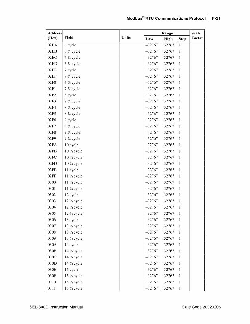
Modbus® RTU Communications Protocol F-51
SEL-300G Instruction Manual Date Code 20020206
Range Address (Hex) Field Units Low High Step
Scale Factor
02EA 6 cycle 32767 32767 1 02EB 6 ¼ cycle 32767 32767 1 02EC 6 ½ cycle 32767 32767 1 02ED 6 ¾ cycle 32767 32767 1 02EE 7 cycle 32767 32767 1 02EF 7 ¼ cycle 32767 32767 1 02F0 7 ½ cycle 32767 32767 1 02F1 7 ¾ cycle 32767 32767 1 02F2 8 cycle 32767 32767 1 02F3 8 ¼ cycle 32767 32767 1 02F4 8 ½ cycle 32767 32767 1 02F5 8 ¾ cycle 32767 32767 1 02F6 9 cycle 32767 32767 1 02F7 9 ¼ cycle 32767 32767 1 02F8 9 ½ cycle 32767 32767 1 02F9 9 ¾ cycle 32767 32767 1 02FA 10 cycle 32767 32767 1 02FB 10 ¼ cycle 32767 32767 1 02FC 10 ½ cycle 32767 32767 1 02FD 10 ¾ cycle 32767 32767 1 02FE 11 cycle 32767 32767 1 02FF 11 ¼ cycle 32767 32767 1 0300 11 ½ cycle 32767 32767 1 0301 11 ¾ cycle 32767 32767 1 0302 12 cycle 32767 32767 1 0303 12 ¼ cycle 32767 32767 1 0304 12 ½ cycle 32767 32767 1 0305 12 ¾ cycle 32767 32767 1 0306 13 cycle 32767 32767 1 0307 13 ¼ cycle 32767 32767 1 0308 13 ½ cycle 32767 32767 1 0309 13 ¾ cycle 32767 32767 1 030A 14 cycle 32767 32767 1 030B 14 ¼ cycle 32767 32767 1 030C 14 ½ cycle 32767 32767 1 030D 14 ¾ cycle 32767 32767 1 030E 15 cycle 32767 32767 1 030F 15 ¼ cycle 32767 32767 1 0310 15 ½ cycle 32767 32767 1 0311 15 ¾ cycle 32767 32767 1
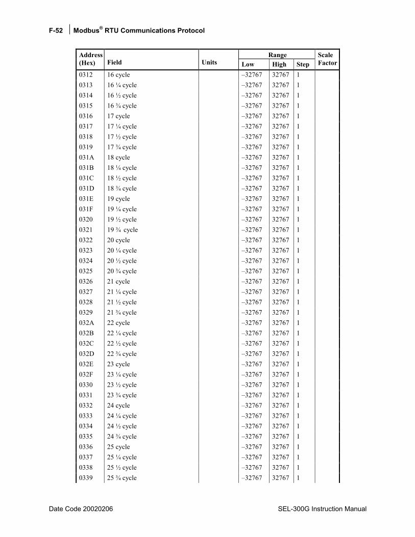
F-52 Modbus® RTU Communications Protocol
Date Code 20020206 SEL-300G Instruction Manual
Range Address (Hex) Field Units Low High Step
Scale Factor
0312 16 cycle 32767 32767 1 0313 16 ¼ cycle 32767 32767 1 0314 16 ½ cycle 32767 32767 1 0315 16 ¾ cycle 32767 32767 1 0316 17 cycle 32767 32767 1 0317 17 ¼ cycle 32767 32767 1 0318 17 ½ cycle 32767 32767 1 0319 17 ¾ cycle 32767 32767 1 031A 18 cycle 32767 32767 1 031B 18 ¼ cycle 32767 32767 1 031C 18 ½ cycle 32767 32767 1 031D 18 ¾ cycle 32767 32767 1 031E 19 cycle 32767 32767 1 031F 19 ¼ cycle 32767 32767 1 0320 19 ½ cycle 32767 32767 1 0321 19 ¾ cycle 32767 32767 1 0322 20 cycle 32767 32767 1 0323 20 ¼ cycle 32767 32767 1 0324 20 ½ cycle 32767 32767 1 0325 20 ¾ cycle 32767 32767 1 0326 21 cycle 32767 32767 1 0327 21 ¼ cycle 32767 32767 1 0328 21 ½ cycle 32767 32767 1 0329 21 ¾ cycle 32767 32767 1 032A 22 cycle 32767 32767 1 032B 22 ¼ cycle 32767 32767 1 032C 22 ½ cycle 32767 32767 1 032D 22 ¾ cycle 32767 32767 1 032E 23 cycle 32767 32767 1 032F 23 ¼ cycle 32767 32767 1 0330 23 ½ cycle 32767 32767 1 0331 23 ¾ cycle 32767 32767 1 0332 24 cycle 32767 32767 1 0333 24 ¼ cycle 32767 32767 1 0334 24 ½ cycle 32767 32767 1 0335 24 ¾ cycle 32767 32767 1 0336 25 cycle 32767 32767 1 0337 25 ¼ cycle 32767 32767 1 0338 25 ½ cycle 32767 32767 1 0339 25 ¾ cycle 32767 32767 1
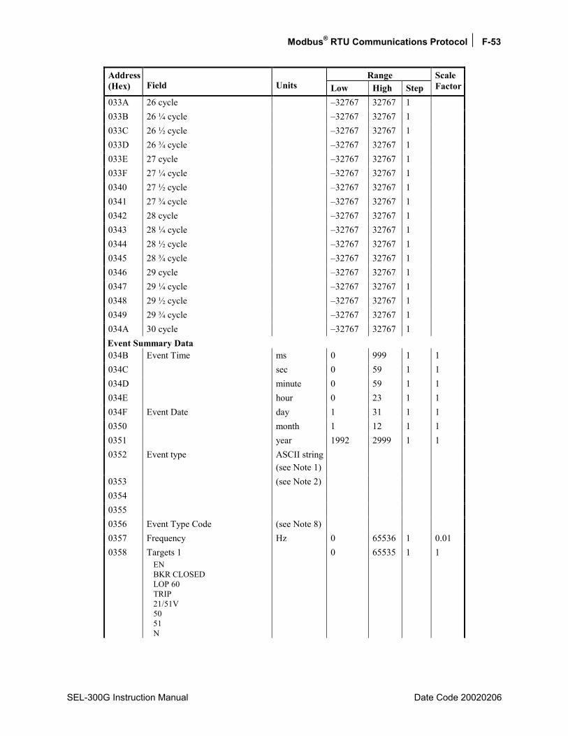
Modbus® RTU Communications Protocol F-53
SEL-300G Instruction Manual Date Code 20020206
Range Address (Hex) Field Units Low High Step
Scale Factor
033A 26 cycle 32767 32767 1 033B 26 ¼ cycle 32767 32767 1 033C 26 ½ cycle 32767 32767 1 033D 26 ¾ cycle 32767 32767 1 033E 27 cycle 32767 32767 1 033F 27 ¼ cycle 32767 32767 1 0340 27 ½ cycle 32767 32767 1 0341 27 ¾ cycle 32767 32767 1 0342 28 cycle 32767 32767 1 0343 28 ¼ cycle 32767 32767 1 0344 28 ½ cycle 32767 32767 1 0345 28 ¾ cycle 32767 32767 1 0346 29 cycle 32767 32767 1 0347 29 ¼ cycle 32767 32767 1 0348 29 ½ cycle 32767 32767 1 0349 29 ¾ cycle 32767 32767 1 034A 30 cycle 32767 32767 1 Event Summary Data 034B Event Time ms 0 999 1 1 034C sec 0 59 1 1 034D minute 0 59 1 1 034E hour 0 23 1 1 034F Event Date day 1 31 1 1 0350 month 1 12 1 1 0351 year 1992 2999 1 1 0352 Event type ASCII string
(see Note 1)
0353 (see Note 2) 0354 0355 0356 Event Type Code (see Note 8) 0357 Frequency Hz 0 65536 1 0.01 0358 Targets 1
EN BKR CLOSED LOP 60 TRIP 21/51V 50 51 N
0 65535 1 1
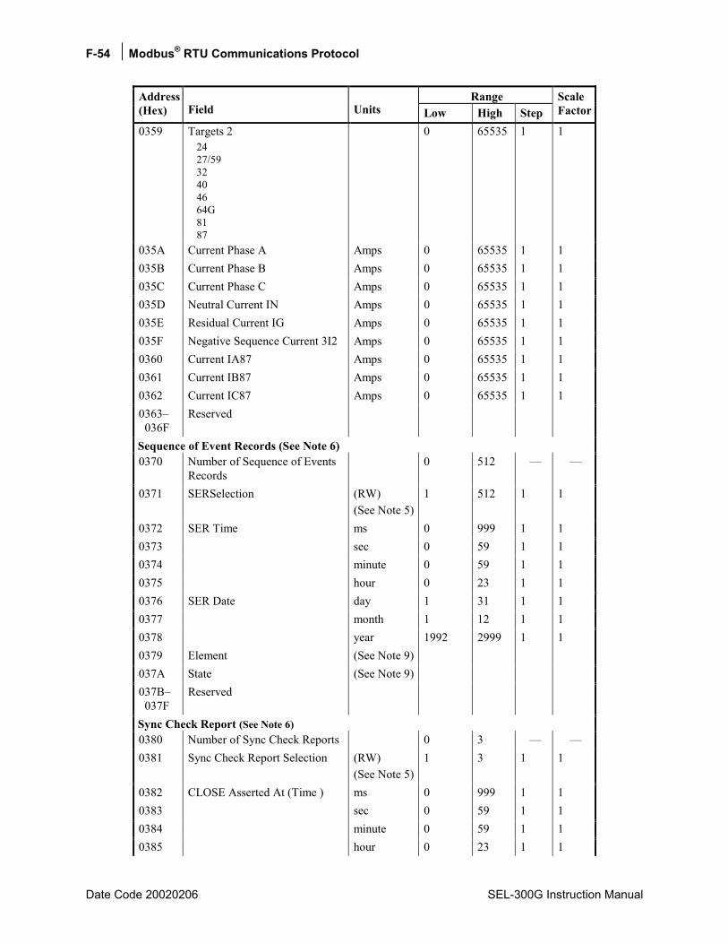
F-54 Modbus® RTU Communications Protocol
Date Code 20020206 SEL-300G Instruction Manual
Range Address (Hex) Field Units Low High Step
Scale Factor
0359 Targets 2 24 27/59 32 40 46 64G 81 87
0 65535 1 1
035A Current Phase A Amps 0 65535 1 1 035B Current Phase B Amps 0 65535 1 1 035C Current Phase C Amps 0 65535 1 1 035D Neutral Current IN Amps 0 65535 1 1 035E Residual Current IG Amps 0 65535 1 1 035F Negative Sequence Current 3I2 Amps 0 65535 1 1 0360 Current IA87 Amps 0 65535 1 1 0361 Current IB87 Amps 0 65535 1 1 0362 Current IC87 Amps 0 65535 1 1 0363 036F
Reserved
Sequence of Event Records (See Note 6) 0370 Number of Sequence of Events
Records 0 512
0371 SERSelection (RW) (See Note 5)
1 512 1 1
0372 SER Time ms 0 999 1 1 0373 sec 0 59 1 1 0374 minute 0 59 1 1 0375 hour 0 23 1 1 0376 SER Date day 1 31 1 1 0377 month 1 12 1 1 0378 year 1992 2999 1 1 0379 Element (See Note 9) 037A State (See Note 9) 037B 037F
Reserved
Sync Check Report (See Note 6) 0380 Number of Sync Check Reports 0 3 0381 Sync Check Report Selection (RW)
(See Note 5)1 3 1 1
0382 CLOSE Asserted At (Time ) ms 0 999 1 1 0383 sec 0 59 1 1 0384 minute 0 59 1 1 0385 hour 0 23 1 1
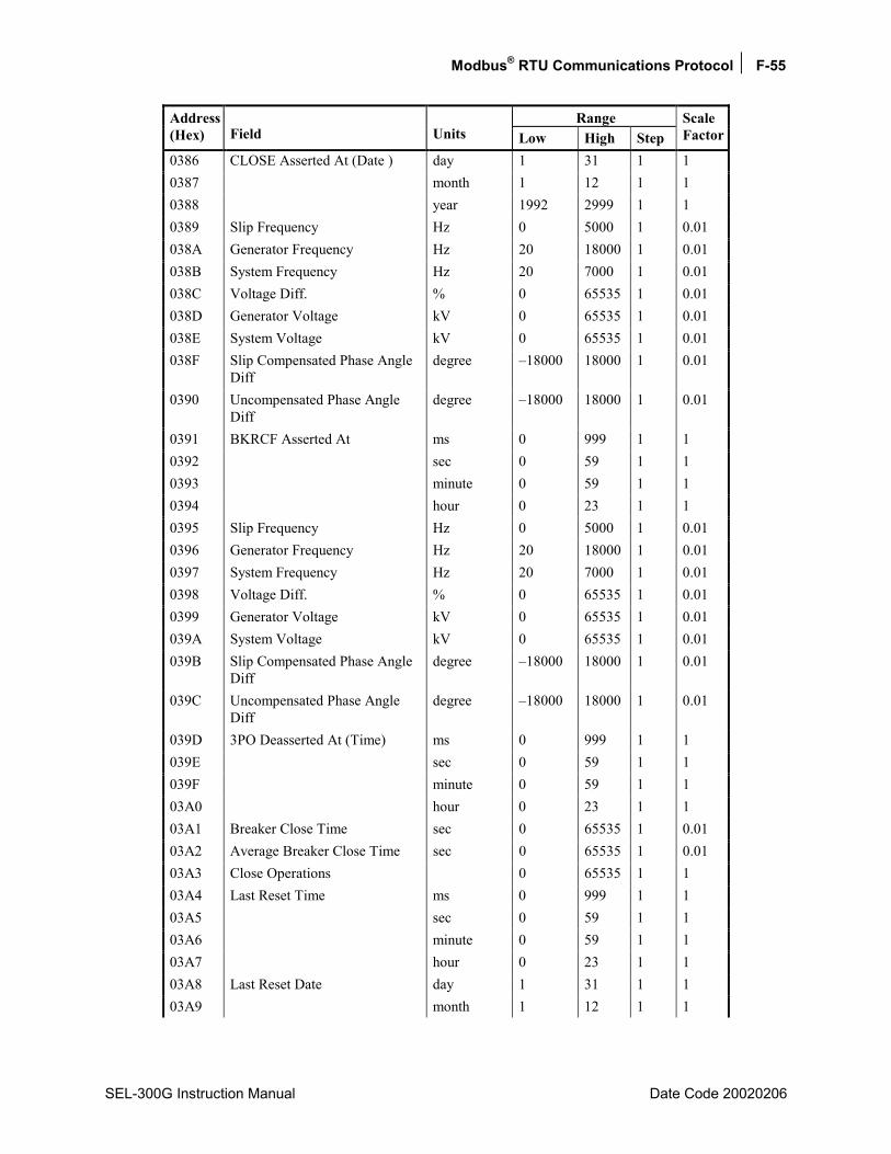
Modbus® RTU Communications Protocol F-55
SEL-300G Instruction Manual Date Code 20020206
Range Address (Hex) Field Units Low High Step
Scale Factor
0386 CLOSE Asserted At (Date ) day 1 31 1 1 0387 month 1 12 1 1 0388 year 1992 2999 1 1 0389 Slip Frequency Hz 0 5000 1 0.01 038A Generator Frequency Hz 20 18000 1 0.01 038B System Frequency Hz 20 7000 1 0.01 038C Voltage Diff. % 0 65535 1 0.01 038D Generator Voltage kV 0 65535 1 0.01 038E System Voltage kV 0 65535 1 0.01 038F Slip Compensated Phase Angle
Diff degree 18000 18000 1 0.01
0390 Uncompensated Phase Angle Diff
degree 18000 18000 1 0.01
0391 BKRCF Asserted At ms 0 999 1 1 0392 sec 0 59 1 1 0393 minute 0 59 1 1 0394 hour 0 23 1 1 0395 Slip Frequency Hz 0 5000 1 0.01 0396 Generator Frequency Hz 20 18000 1 0.01 0397 System Frequency Hz 20 7000 1 0.01 0398 Voltage Diff. % 0 65535 1 0.01 0399 Generator Voltage kV 0 65535 1 0.01 039A System Voltage kV 0 65535 1 0.01 039B Slip Compensated Phase Angle
Diff degree 18000 18000 1 0.01
039C Uncompensated Phase Angle Diff
degree 18000 18000 1 0.01
039D 3PO Deasserted At (Time) ms 0 999 1 1 039E sec 0 59 1 1 039F minute 0 59 1 1 03A0 hour 0 23 1 1 03A1 Breaker Close Time sec 0 65535 1 0.01 03A2 Average Breaker Close Time sec 0 65535 1 0.01 03A3 Close Operations 0 65535 1 1 03A4 Last Reset Time ms 0 999 1 1 03A5 sec 0 59 1 1 03A6 minute 0 59 1 1 03A7 hour 0 23 1 1 03A8 Last Reset Date day 1 31 1 1 03A9 month 1 12 1 1
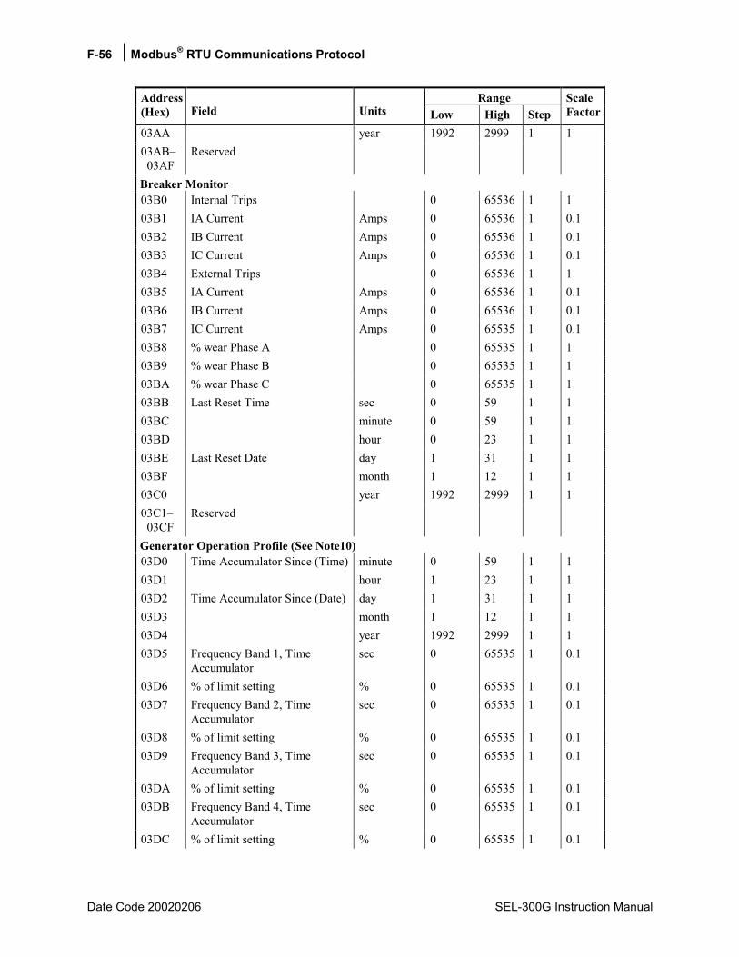
F-56 Modbus® RTU Communications Protocol
Date Code 20020206 SEL-300G Instruction Manual
Range Address (Hex) Field Units Low High Step
Scale Factor
03AA year 1992 2999 1 1 03AB 03AF
Reserved
Breaker Monitor 03B0 Internal Trips 0 65536 1 1 03B1 IA Current Amps 0 65536 1 0.1 03B2 IB Current Amps 0 65536 1 0.1 03B3 IC Current Amps 0 65536 1 0.1 03B4 External Trips 0 65536 1 1 03B5 IA Current Amps 0 65536 1 0.1 03B6 IB Current Amps 0 65536 1 0.1 03B7 IC Current Amps 0 65535 1 0.1 03B8 % wear Phase A 0 65535 1 1 03B9 % wear Phase B 0 65535 1 1 03BA % wear Phase C 0 65535 1 1 03BB Last Reset Time sec 0 59 1 1 03BC minute 0 59 1 1 03BD hour 0 23 1 1 03BE Last Reset Date day 1 31 1 1 03BF month 1 12 1 1 03C0 year 1992 2999 1 1 03C1 03CF
Reserved
Generator Operation Profile (See Note10) 03D0 Time Accumulator Since (Time) minute 0 59 1 1 03D1 hour 1 23 1 1 03D2 Time Accumulator Since (Date) day 1 31 1 1 03D3 month 1 12 1 1 03D4 year 1992 2999 1 1 03D5 Frequency Band 1, Time
Accumulator sec 0 65535 1 0.1
03D6 % of limit setting % 0 65535 1 0.1 03D7 Frequency Band 2, Time
Accumulator sec 0 65535 1 0.1
03D8 % of limit setting % 0 65535 1 0.1 03D9 Frequency Band 3, Time
Accumulator sec 0 65535 1 0.1
03DA % of limit setting % 0 65535 1 0.1 03DB Frequency Band 4, Time
Accumulator sec 0 65535 1 0.1
03DC % of limit setting % 0 65535 1 0.1
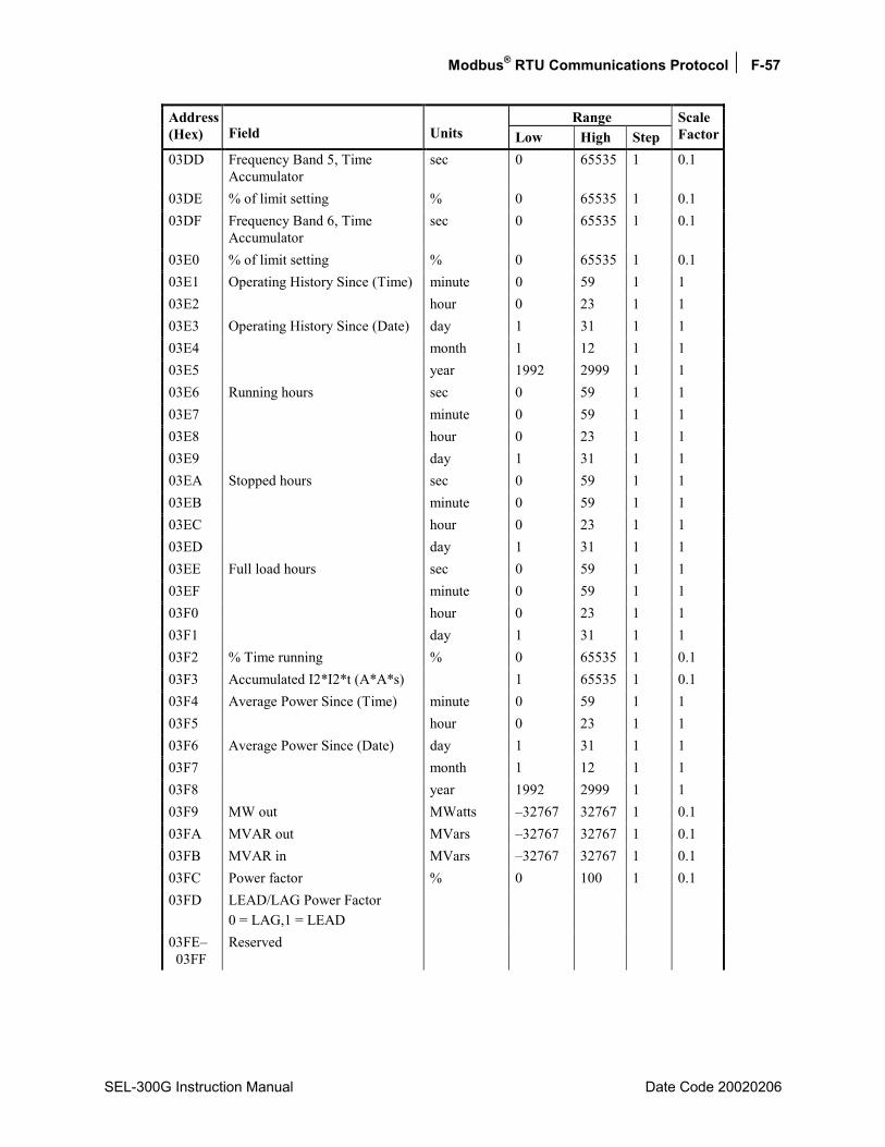
Modbus® RTU Communications Protocol F-57
SEL-300G Instruction Manual Date Code 20020206
Range Address (Hex) Field Units Low High Step
Scale Factor
03DD Frequency Band 5, Time Accumulator
sec 0 65535 1 0.1
03DE % of limit setting % 0 65535 1 0.1 03DF Frequency Band 6, Time
Accumulator sec 0 65535 1 0.1
03E0 % of limit setting % 0 65535 1 0.1 03E1 Operating History Since (Time) minute 0 59 1 1 03E2 hour 0 23 1 1 03E3 Operating History Since (Date) day 1 31 1 1 03E4 month 1 12 1 1 03E5 year 1992 2999 1 1 03E6 Running hours sec 0 59 1 1 03E7 minute 0 59 1 1 03E8 hour 0 23 1 1 03E9 day 1 31 1 1 03EA Stopped hours sec 0 59 1 1 03EB minute 0 59 1 1 03EC hour 0 23 1 1 03ED day 1 31 1 1 03EE Full load hours sec 0 59 1 1 03EF minute 0 59 1 1 03F0 hour 0 23 1 1 03F1 day 1 31 1 1 03F2 % Time running % 0 65535 1 0.1 03F3 Accumulated I2*I2*t (A*A*s) 1 65535 1 0.1 03F4 Average Power Since (Time) minute 0 59 1 1 03F5 hour 0 23 1 1 03F6 Average Power Since (Date) day 1 31 1 1 03F7 month 1 12 1 1 03F8 year 1992 2999 1 1 03F9 MW out MWatts 32767 32767 1 0.1 03FA MVAR out MVars 32767 32767 1 0.1 03FB MVAR in MVars 32767 32767 1 0.1 03FC Power factor % 0 100 1 0.1 03FD LEAD/LAG Power Factor
0 = LAG,1 = LEAD
03FE 03FF
Reserved
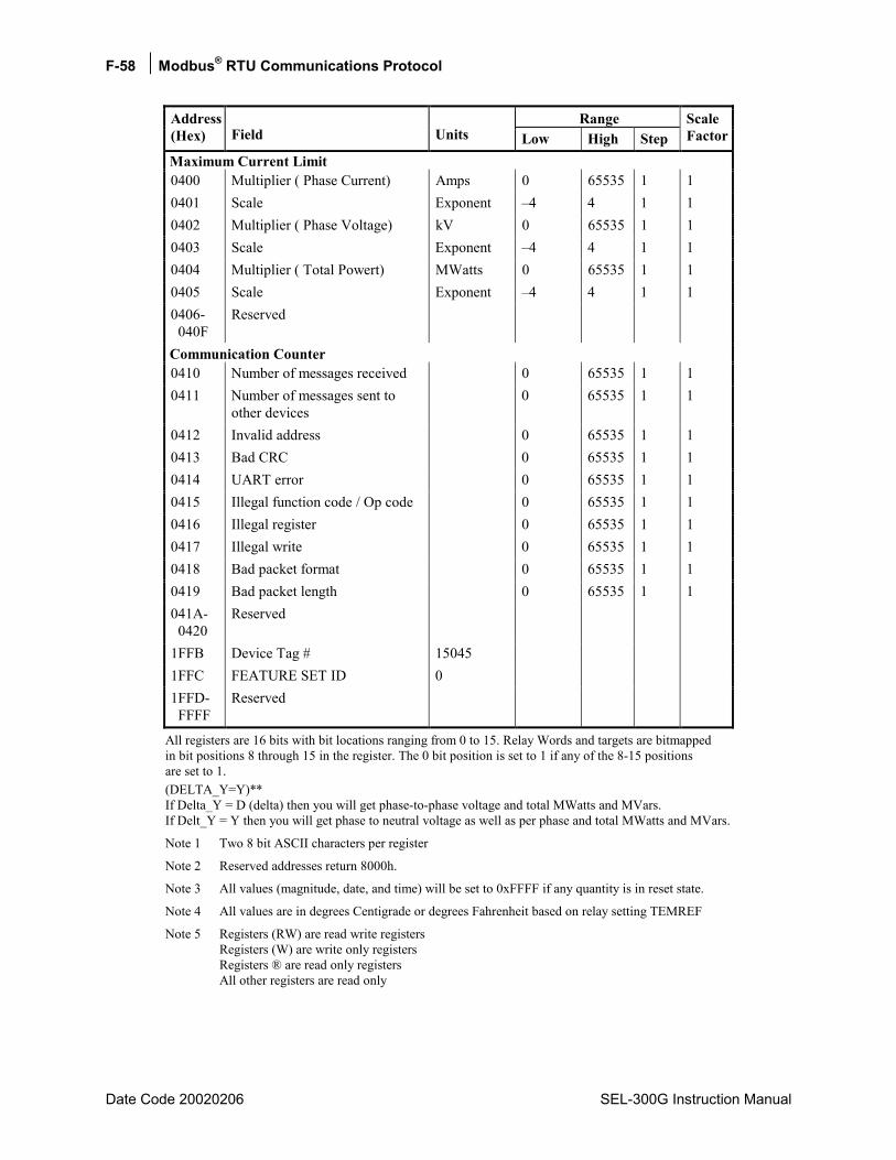
F-58 Modbus® RTU Communications Protocol
Date Code 20020206 SEL-300G Instruction Manual
Range Address (Hex) Field Units Low High Step
Scale Factor
Maximum Current Limit 0400 Multiplier ( Phase Current) Amps 0 65535 1 1 0401 Scale Exponent 4 4 1 1 0402 Multiplier ( Phase Voltage) kV 0 65535 1 1 0403 Scale Exponent 4 4 1 1 0404 Multiplier ( Total Powert) MWatts 0 65535 1 1 0405 Scale Exponent 4 4 1 1 0406- 040F
Reserved
Communication Counter 0410 Number of messages received 0 65535 1 1 0411 Number of messages sent to
other devices 0 65535 1 1
0412 Invalid address 0 65535 1 1 0413 Bad CRC 0 65535 1 1 0414 UART error 0 65535 1 1 0415 Illegal function code / Op code 0 65535 1 1 0416 Illegal register 0 65535 1 1 0417 Illegal write 0 65535 1 1 0418 Bad packet format 0 65535 1 1 0419 Bad packet length 0 65535 1 1 041A- 0420
Reserved
1FFB Device Tag # 15045 1FFC FEATURE SET ID 0 1FFD- FFFF
Reserved
All registers are 16 bits with bit locations ranging from 0 to 15. Relay Words and targets are bitmapped in bit positions 8 through 15 in the register. The 0 bit position is set to 1 if any of the 8-15 positions are set to 1. (DELTA_Y=Y)** If Delta_Y = D (delta) then you will get phase-to-phase voltage and total MWatts and MVars. If Delt_Y = Y then you will get phase to neutral voltage as well as per phase and total MWatts and MVars.
Note 1 Two 8 bit ASCII characters per register
Note 2 Reserved addresses return 8000h.
Note 3 All values (magnitude, date, and time) will be set to 0xFFFF if any quantity is in reset state.
Note 4 All values are in degrees Centigrade or degrees Fahrenheit based on relay setting TEMREF
Note 5 Registers (RW) are read write registers Registers (W) are write only registers Registers ® are read only registers All other registers are read only

Modbus® RTU Communications Protocol F-59
SEL-300G Instruction Manual Date Code 20020206
Note 6 Event and History Reporting: The Modbus Register Map listed above provides a feature that allows you to download complete event data, History data, SER data, Sync Check Report data, or Generator Operation Profile data via Modbus. The SEL-300G relay stores the twenty-nine latest event reports, twenty-nine latest event summaries (History data), 512 SER, Generator Operating Profile data, and three Sync Check Report in nonvolatile memory. If BKRCF is not asserted during synchronism, then the time for RKRCF asserted will be 8000h, 8000h, 8000h, 8000h, and the following information, from slip freqency to uncompensated phase angle difference, will all be 8000h. The event report extraction will be through 68 channels. These channels must be assigned as follows:
Ch1 IA Ch7 VB Ch13 IA87 Ch2 IB Ch8 VC Ch14 IB87 Ch3 IC Ch9 VN Ch15 IC87 Ch4 IN Ch10 VS Ch16 Event Report Summary Ch5 IG Ch11 Vdc Ch6 VA Ch12 Frequency
Ch17 to Ch68 RELAY WORDS
The main intent of the event report extraction is as follows: At each quarter cycle the following information should be retrievable: Input currents and Voltages, Vdc and Frequency, and the 51 rows of relay words associated with the applications.
Note 7 The scaling factor for ch6-ch11 is 0.1; the scaling factor for ch12 is 0.01; the rest of them use 1 as scaling factor
Note 8 EVENT TYPES: ASCII CODE TRIG 1 PULSE 2 TRIP 4 ER 8
Note 9 Element field in SER report will have index number defined in Table F.7. Element field = 0xffff means that this is Relay newly powered up or settings changed. Event State field in SER report will be 0 or 1
Note 10 If E81AC = N, then all data from row of 81AC OffFreq Time Accumulator Since to row of Frequency Band 6, Time Accumulator and % of limit setting will be set as 0x8000.

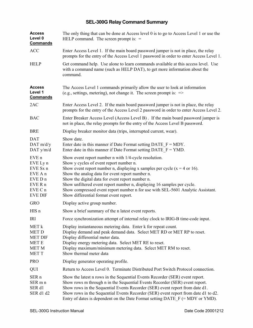
SEL-300G Instruction Manual Date Code 20001212
SEL-300G Relay Command Summary
Access Level 0 Commands
The only thing that can be done at Access level 0 is to go to Access Level 1 or use the HELP command. The screen prompt is: =
ACC Enter Access Level 1. If the main board password jumper is not in place, the relay prompts for the entry of the Access Level 1 password in order to enter Access Level 1.
HELP Get command help. Use alone to learn commands available at this access level. Use with a command name (such as HELP DAT), to get more information about the command.
Access Level 1 Commands
The Access Level 1 commands primarily allow the user to look at information (e.g., settings, metering), not change it. The screen prompt is: =>
2AC Enter Access Level 2. If the main board password jumper is not in place, the relay prompts for the entry of the Access Level 2 password in order to enter Access Level 2.
BAC Enter Breaker Access Level (Access Level B) . If the main board password jumper is not in place, the relay prompts for the entry of the Access Level B password.
BRE Display breaker monitor data (trips, interrupted current, wear).
DAT Show date. DAT m/d/y Enter date in this manner if Date Format setting DATE_F = MDY. DAT y/m/d Enter date in this manner if Date Format setting DATE_F = YMD.
EVE n Show event report number n with 1/4-cycle resolution. EVE Ly n Show y cycles of event report number n. EVE Sx n Show event report number n, displaying x samples per cycle (x = 4 or 16). EVE A n Show the analog data for event report number n. EVE D n Show the digital data for event report number n. EVE R n Show unfiltered event report number n, displaying 16 samples per cycle. EVE C n Show compressed event report number n for use with SEL-5601 Analytic Assistant. EVE DIF Show differential format event report.
GRO Display active group number.
HIS n Show a brief summary of the n latest event reports.
IRI Force synchronization attempt of internal relay clock to IRIG-B time-code input.
MET k Display instantaneous metering data. Enter k for repeat count. MET D Display demand and peak demand data. Select MET RD or MET RP to reset. MET DIF Display differential meter data. MET E Display energy metering data. Select MET RE to reset. MET M Display maximum/minimum metering data. Select MET RM to reset. MET T Show thermal meter data
PRO Display generator operating profile.
QUI Return to Access Level 0. Terminate Distributed Port Switch Protocol connection.
SER n Show the latest n rows in the Sequential Events Recorder (SER) event report. SER m n Show rows m through n in the Sequential Events Recorder (SER) event report. SER d1 Show rows in the Sequential Events Recorder (SER) event report from date d1. SER d1 d2 Show rows in the Sequential Events Recorder (SER) event report from date d1 to d2.
Entry of dates is dependent on the Date Format setting DATE_F (= MDY or YMD).
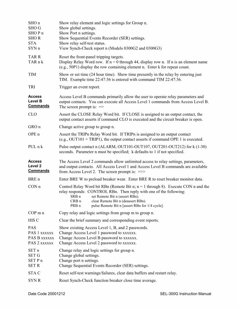
Date Code 20001212 SEL-300G Instruction Manual
SHO n Show relay element and logic settings for Group n. SHO G Show global settings. SHO P n Show Port n settings. SHO R Show Sequential Events Recorder (SER) settings. STA Show relay self-test status. SYN n View Synch-Check report n (Models 0300G2 and 0300G3)
TAR R Reset the front-panel tripping targets. TAR n k Display Relay Word row. If n = 0 through 44, display row n. If n is an element name
(e.g., 50P1) display the row containing element n. Enter k for repeat count.
TIM Show or set time (24 hour time). Show time presently in the relay by entering just TIM. Example time 22:47:36 is entered with command TIM 22:47:36.
TRI Trigger an event report.
Access Level B Commands
Access Level B commands primarily allow the user to operate relay parameters and output contacts. You can execute all Access Level 1 commands from Access Level B. The screen prompt is: =>
CLO Assert the CLOSE Relay Word bit. If CLOSE is assigned to an output contact, the output contact asserts if command CLO is executed and the circuit breaker is open.
GRO n Change active group to group n.
OPE n Assert the TRIPn Relay Word bit. If TRIPn is assigned to an output contact (e.g., OUT101 = TRIP1), the output contact asserts if command OPE 1 is executed.
PUL n k Pulse output contact n (ALARM, OUT101-OUT107, OUT201-OUT212) for k (1-30) seconds. Parameter n must be specified; k defaults to 1 if not specified.
Access Level 2 Commands
The Access Level 2 commands allow unlimited access to relay settings, parameters, and output contacts. All Access Level 1 and Access Level B commands are available from Access Level 2. The screen prompt is: =>>
BRE n Enter BRE W to preload breaker wear. Enter BRE R to reset breaker monitor data.
CON n Control Relay Word bit RBn (Remote Bit n; n = 1 through 8). Execute CON n and the relay responds: CONTROL RBn. Then reply with one of the following:
SRB n set Remote Bit n (assert RBn). CRB n clear Remote Bit n (deassert RBn). PRB n pulse Remote Bit n [assert RBn for 1/4 cycle].
COP m n Copy relay and logic settings from group m to group n.
HIS C Clear the brief summary and corresponding event reports.
PAS Show existing Access Level 1, B, and 2 passwords. PAS 1 xxxxxx Change Access Level 1 password to xxxxxx. PAS B xxxxxx Change Access Level B password to xxxxxx. PAS 2 xxxxxx Change Access Level 2 password to xxxxxx.
SET n Change relay and logic settings for group n. SET G Change global settings. SET P n Change port n settings. SET R Change Sequential Events Recorder (SER) settings.
STA C Reset self-test warnings/failures, clear data buffers and restart relay.
SYN R Reset Synch-Check function breaker close time average.
Recommended