Interlocking Solutions
13-3-2009 Rev.C E 1 - Interlocking solutions
Section E
ASTAVA
INTERLOCKING
SOLUTIONS
Interlocking solutions
E 2 - Interlocking solutions 13-3-2009 Rev.C
Table of content page 1) Overpressure protection philosophy 3 2) General information 3 3) Applications 3 4) Site preparation 4 5) HIPPS or PPS 4 6) Astava Interlocking Solutions 5
6.1 Interlocking manifold .............................................................. 5 6.1.1. Operating an Interlocking manifold ....................................... 6 6.1.2. IEC 61508: SIL 4 Certification................................................. 6 6.1.3. Flowschemes........................................................................... 6 6.1.4. Transbar Mounting.................................................................. 6 6.1.5. P/T ratings for interlocking manifolds................................... 6 6.1.6. Materials................................................................................... 7 6.1.7. Accessories ............................................................................. 7 6.1.8. Ordering matrix Interlocking manifold .................................. 8 6.2 Ordering matrix Interlocking housing ................................... 9
7) Photo overview of different solution supplied 10 8) Astava flexibility, other options…… 11
ASTAVA B.V. Tel: +31-(0)522-237030 Fax: +31-(0)522-237040
7944 HS MEPPEL THE NETHERLANDS E-mail: [email protected] Internet: www.astava.com
Interlocking Solutions
13-3-2009 Rev.C E 3 - Interlocking solutions
1) Overpressure protection philosophy Protection against overpressure is normally obtained by means of a cascade of independant layers of defence, such as:
- Pressure control system to maintain the process within its normal operating envelope
- Safeguarding system to maintain the process within the design pressure (DP) limits and consequently maintain system integrity
- Pressure protection by means of a pressure safety relief valve (PSV) or HIPP system, as last
layer of defence to maintain the process system within maximum allowable incidental pressure (MAIP = 1.1 x DP). The dynamic response of the safeguarding layer (HPSD) should avoid activation of the last layer of defence (HIPPS). HIPPS shall function independantly of any other layer of defence. The combined use of equipment for HIPPS shall not be tolerated.
2) General information The installation of a non-relieving high integrity pressure protection system (HIPPS) may be considered to prevent and/or reduce the release of toxic gases or large volumes of non-toxic gas, thereby avoiding or reducing environmental impact. The system may also be used for detecting pipeline rupture. In order to prevent operational errors, an interlocking manifold with a foolproof “sliding key” design, is part of the system. This “sliding key” principle will only permit closing and opening of isolating valves and vent valves in a pre-determined safe sequence. This will allow on-line calibration of instruments while preventing any faulty operation and consequently eliminating undesired (nuisance) shut-downs. 3) Applications
- Pipeline Overpressure Protection Systems o replacing mechanical blow-down valves (PSV’s) at both ends of a gas transport line.
- Gas wells, gas treatment plants and underground storage installations
o avoiding the necessity for very high, large capacity, flares
- Petrochemical and sour gas processing installations o avoiding large safety release emissions to atmosphere
- Economical spec-break design in process installations and compressor stations
o avoiding pressure beyond the most economical design pressure.
- Protection of river crossings and railway underpasses.
Interlocking solutions
E 4 - Interlocking solutions 13-3-2009 Rev.C
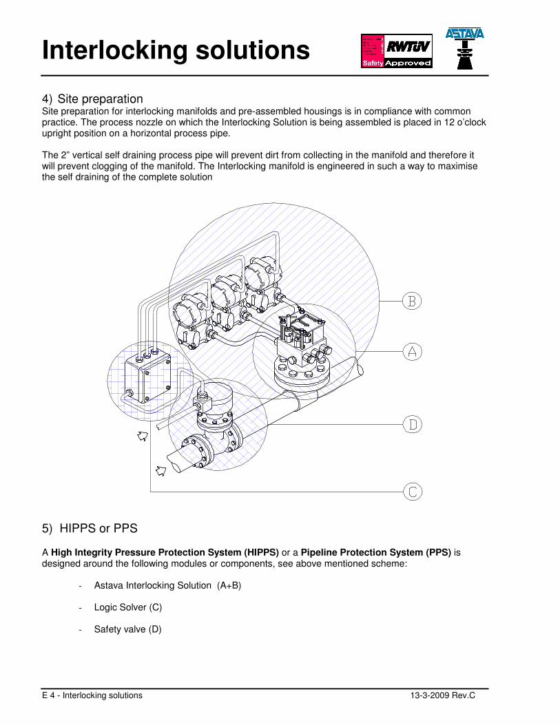
4) Site preparation Site preparation for interlocking manifolds and pre-assembled housings is in compliance with common practice. The process nozzle on which the Interlocking Solution is being assembled is placed in 12 o’clock upright position on a horizontal process pipe. The 2” vertical self draining process pipe will prevent dirt from collecting in the manifold and therefore it will prevent clogging of the manifold. The Interlocking manifold is engineered in such a way to maximise the self draining of the complete solution
5) HIPPS or PPS A High Integrity Pressure Protection System (HIPPS) or a Pipeline Protection System (PPS) is designed around the following modules or components, see above mentioned scheme:
- Astava Interlocking Solution (A+B)
- Logic Solver (C)
- Safety valve (D)
Interlocking Solutions
13-3-2009 Rev.C E 5 - Interlocking solutions
6) Astava Interlocking Solutions The solutions offered by Astava consist out of two separate parts:
1. Interlocking manifold
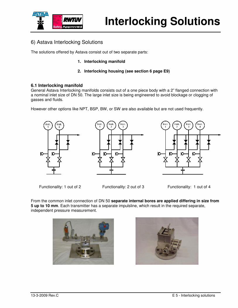
2. Interlocking housing (see section 6 page E9) 6.1 Interlocking manifold General Astava Interlocking manifolds consists out of a one piece body with a 2” flanged connection with a nominal inlet size of DN 50. The large inlet size is being engineered to avoid blockage or clogging of gasses and fluids. However other options like NPT, BSP, BW, or SW are also available but are not used frequently.
Functionality: 1 out of 2
Functionality: 2 out of 3
Functionality: 1 out of 4
From the common inlet connection of DN 50 separate internal bores are applied differing in size from 5 up to 10 mm. Each transmitter has a separate impulsline, which result in the required separate, independent pressure measurement.
Interlocking solutions
E 6 - Interlocking solutions 13-3-2009 Rev.C
6.1.1. Operating an Interlocking manifold The sliding key arrangement mechanically enables operators to close one isolating valve at a time, thereby isolating one pressure transmitter or pressure switch only. After closing the isolating valve, the key is at a lower level in the slotted plate. It can only be moved to the corresponding vent valve, which is now at the same lower level. The sliding key system is valid for all types of interlocking manifolds. The valves being on different levels, the sequence of opening and closing the various valves cannot be changed. Operator mistakes cannot be made. The mechanical interlocking system is providing maximum safety for the operator due to sequence of operation as well as maximum availability of client’s installation or piping system. 6.1.2. IEC 61508: SIL 4 Certification The complete operating facility, often called the Interlocking manifold or High Integrity Manifold Block (HIMB) has been tested and examined by TUV Systems GmbH in Germany in accordance with the IEC 61508. The test resulted in certification of the Astava Interlocking with a Probability of Failure on Demand (PFD-value) of:
PFD avg = 4,26 e-5 resulting in a Safety Integrity Level
Certified SIL 4
The complete report on SIL 4 certification is available on request at Astava 6.1.3. Flowschemes The flowscheme within the interlocking from process connection to measuring device can differ in various option, herewith the most common:
- Block-bleed-block-test - Block-block-bleed-test - Block-bleed-test
6.1.4. Transbar Mounting As a standard Astava applies a Transbar mounting for all measuring devices which eliminates all compression fittings and tubing. The Transbar is bolted to the Interlocking Manifold and flanged pressure transmitters (DIN 19213) can be bolted directly. For screwed pressure transmitters and pressure switches Astava provides adaptors which can be bolted to the Transbar. 6.1.5. P/T ratings for interlocking manifolds The P/T rating of an interlocking manifold is primarily determined by flange rating and flange material. Standard ratings are 150 -2500 lbs or up to 10.000 psi. Also important are the maximum given to the stempacking applied within the Interlocking operating valves.
Interlocking Solutions
13-3-2009 Rev.C E 7 - Interlocking solutions
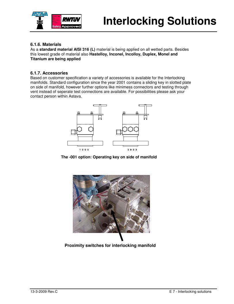
6.1.6. Materials As a standard material AISI 316 (L) material is being applied on all wetted parts. Besides this lowest grade of material also Hastelloy, Inconel, Incolloy, Duplex, Monel and Titanium are being applied 6.1.7. Accessories Based on customer specification a variety of accessories is available for the Interlocking manifolds. Standard configuration since the year 2001 contains a sliding key in slotted plate on side of manifold, however further options like minimess connectors and testing through vent instead of seperate test connections are available. For possibilities please ask your contact person within Astava.
The -001 option: Operating key on side of manifold Proximity switches for interlocking manifold
Interlocking solutions
E 8 - Interlocking solutions 13-3-2009 Rev.C
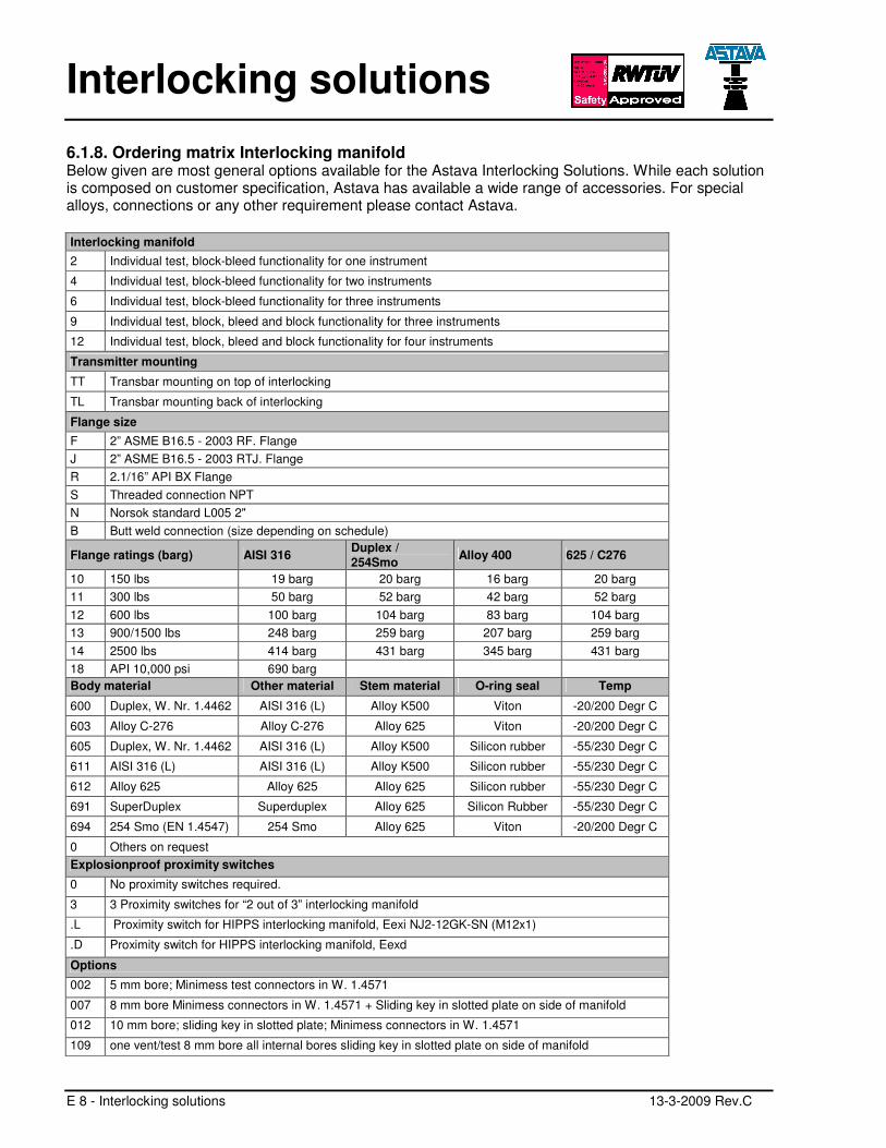
6.1.8. Ordering matrix Interlocking manifold Below given are most general options available for the Astava Interlocking Solutions. While each solution is composed on customer specification, Astava has available a wide range of accessories. For special alloys, connections or any other requirement please contact Astava.
Interlocking manifold 2 Individual test, block-bleed functionality for one instrument
4 Individual test, block-bleed functionality for two instruments
6 Individual test, block-bleed functionality for three instruments
9 Individual test, block, bleed and block functionality for three instruments
12 Individual test, block, bleed and block functionality for four instruments
Transmitter mounting
TT Transbar mounting on top of interlocking
TL Transbar mounting back of interlocking
Flange size F 2” ASME B16.5 - 2003 RF. Flange J 2” ASME B16.5 - 2003 RTJ. Flange R 2.1/16” API BX Flange S Threaded connection NPT N Norsok standard L005 2" B Butt weld connection (size depending on schedule)
Flange ratings (barg) AISI 316 Duplex / 254Smo Alloy 400 625 / C276
10 150 lbs 19 barg 20 barg 16 barg 20 barg 11 300 lbs 50 barg 52 barg 42 barg 52 barg 12 600 lbs 100 barg 104 barg 83 barg 104 barg 13 900/1500 lbs 248 barg 259 barg 207 barg 259 barg 14 2500 lbs 414 barg 431 barg 345 barg 431 barg 18 API 10,000 psi 690 barg Body material Other material Stem material O-ring seal Temp
600 Duplex, W. Nr. 1.4462 AISI 316 (L) Alloy K500 Viton -20/200 Degr C
603 Alloy C-276 Alloy C-276 Alloy 625 Viton -20/200 Degr C
605 Duplex, W. Nr. 1.4462 AISI 316 (L) Alloy K500 Silicon rubber -55/230 Degr C
611 AISI 316 (L) AISI 316 (L) Alloy K500 Silicon rubber -55/230 Degr C
612 Alloy 625 Alloy 625 Alloy 625 Silicon rubber -55/230 Degr C
691 SuperDuplex Superduplex Alloy 625 Silicon Rubber -55/230 Degr C
694 254 Smo (EN 1.4547) 254 Smo Alloy 625 Viton -20/200 Degr C
0 Others on request Explosionproof proximity switches
0 No proximity switches required.
3 3 Proximity switches for “2 out of 3” interlocking manifold
.L Proximity switch for HIPPS interlocking manifold, Eexi NJ2-12GK-SN (M12x1)
.D Proximity switch for HIPPS interlocking manifold, Eexd
Options
002 5 mm bore; Minimess test connectors in W. 1.4571
007 8 mm bore Minimess connectors in W. 1.4571 + Sliding key in slotted plate on side of manifold
012 10 mm bore; sliding key in slotted plate; Minimess connectors in W. 1.4571
109 one vent/test 8 mm bore all internal bores sliding key in slotted plate on side of manifold
Interlocking Solutions
13-3-2009 Rev.C E 9 - Interlocking solutions
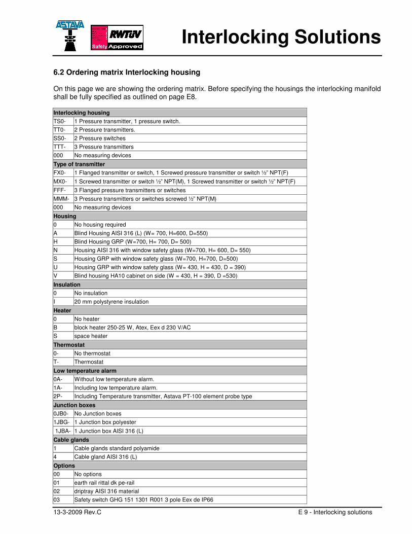
6.2 Ordering matrix Interlocking housing On this page we are showing the ordering matrix. Before specifying the housings the interlocking manifold shall be fully specified as outlined on page E8. Interlocking housing TS0- 1 Pressure transmitter, 1 pressure switch. TT0- 2 Pressure transmitters. SS0- 2 Pressure switches TTT- 3 Pressure transmitters 000 No measuring devices
Type of transmitter FX0- 1 Flanged transmitter or switch, 1 Screwed pressure transmitter or switch ½” NPT(F) MX0- 1 Screwed transmitter or switch ½” NPT(M), 1 Screwed transmitter or switch ½” NPT(F) FFF- 3 Flanged pressure transmitters or switches MMM- 3 Pressure transmitters or switches screwed ½” NPT(M) 000 No measuring devices
Housing 0 No housing required A Blind Housing AISI 316 (L) (W= 700, H=600, D=550) H Blind Housing GRP (W=700, H= 700, D= 500) N Housing AISI 316 with window safety glass (W=700, H= 600, D= 550) S Housing GRP with window safety glass (W=700, H=700, D=500) U Housing GRP with window safety glass (W= 430, H = 430, D = 390) V Blind housing HA10 cabinet on side (W = 430, H = 390, D =530)
Insulation 0 No insulation I 20 mm polystyrene insulation Heater 0 No heater B block heater 250-25 W, Atex, Eex d 230 V/AC S space heater
Thermostat 0- No thermostat T- Thermostat
Low temperature alarm 0A- Without low temperature alarm. 1A- Including low temperature alarm. 2P- Including Temperature transmitter, Astava PT-100 element probe type
Junction boxes 0JB0- No Junction boxes 1JBG- 1 Junction box polyester
1JBA- 1 Junction box AISI 316 (L) Cable glands 1 Cable glands standard polyamide 4 Cable gland AISI 316 (L)
Options 00 No options 01 earth rail rittal dk pe-rail 02 driptray AISI 316 material 03 Safety switch GHG 151 1301 R001 3 pole Eex de IP66
Interlocking solutions
E 10 - Interlocking solutions 13-3-2009 Rev.C
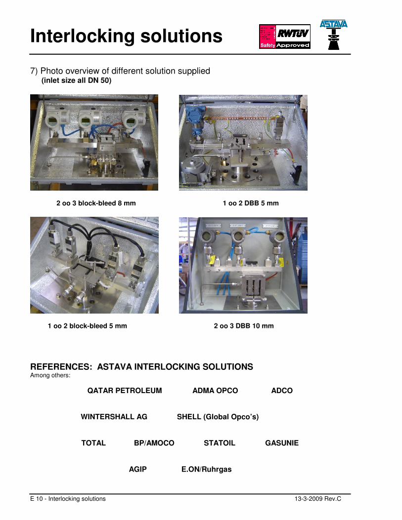
7) Photo overview of different solution supplied (inlet size all DN 50)
2 oo 3 block-bleed 8 mm 1 oo 2 DBB 5 mm
1 oo 2 block-bleed 5 mm 2 oo 3 DBB 10 mm
REFERENCES: ASTAVA INTERLOCKING SOLUTIONS Among others:
QATAR PETROLEUM ADMA OPCO ADCO
WINTERSHALL AG SHELL (Global Opco’s)
TOTAL BP/AMOCO STATOIL GASUNIE
AGIP E.ON/Ruhrgas
Interlocking Solutions
13-3-2009 Rev.C E 11 - Interlocking solutions
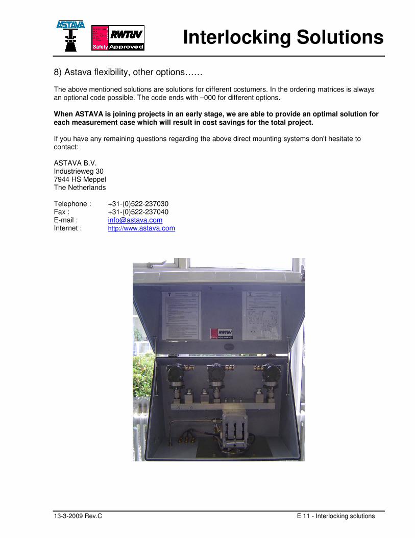
8) Astava flexibility, other options…… The above mentioned solutions are solutions for different costumers. In the ordering matrices is always an optional code possible. The code ends with –000 for different options. When ASTAVA is joining projects in an early stage, we are able to provide an optimal solution for each measurement case which will result in cost savings for the total project. If you have any remaining questions regarding the above direct mounting systems don't hesitate to contact: ASTAVA B.V. Industrieweg 30 7944 HS Meppel The Netherlands Telephone : +31-(0)522-237030 Fax : +31-(0)522-237040 E-mail : [email protected] Internet : http://www.astava.com
Recommended