Scan Matching for Graph SLAM in Indoor Dynamic Scenarios
Jingchun Yin, Luca Carlone, Stefano Rosa, Muhammad Latif Anjum and Basilio BonaDipartimento di Automatica e Informatica (DAUIN)
Politecnico di Torino, Italy{jingchun.yin, luca.carlone, stefano.rosa, muhammad.anjum, basilio.bona}@polito.it
Abstract
SLAM (Simultaneous Localization And Mapping)plays an essential and important role for mobile roboticautonomous navigation. SLAM in dynamic environ-ments with moving objects is a challenging problem.We focus on scan matching for Graph-SLAM in indoordynamic scenarios. Scan matching algorithm is pro-posed and implemented, which consists of the follow-ing phases: first, conditioned Hough Transform basedsegmentation is performed to extract and group linefeatures; second, occupancy-analysis based moving ob-jects detection is done to detect and discard the seg-ments corresponding to the moving objects; third, lin-ear regression based line feature matching is executedto estimate the roto-translation parameters. Simulationsto estimate roto-translation and the entire trajectory ofthe robot effectively verified the robustness of this al-gorithm in a dynamic scenario. The proposed algorithmis based on the line features of the indoor environment.It is robust to disturbances from moving objects in thedynamic scenario, and is especially suitable for the casewhen large rotational displacement is present.
IntroductionSLAM (Simultaneous Localization And Mapping) aims atestimating the travelled trajectory of a mobile robot. SLAMin dynamic scenarios with moving objects is a critical appli-cation for mobile robots to achieve robust autonomy in nav-igation and safe coexistence with humans in populated en-vironments. In many cases, the mobile robot deploys LaserRange-finders to perceive the obstacles in the environmentand Wheel-Encoders to obtain its own odometric informa-tion. Based on the sensor data, Graph-SLAM constructs andoptimizes one topological graph to solve the SLAM prob-lem. We do research on scan matching to construct the edgesfor graph SLAM in dynamic scenario. Scan matching tar-gets at estimating the relative roto-translation displacementbetween two robot poses. This geometrical displacement re-lationship represents an edge constraint in the graph.
In the literature of scan matching, there are generally twocategories of approaches: point-based matching and feature-based matching. Point-based matching uses the direct point
Copyright c© 2014, Association for the Advancement of ArtificialIntelligence (www.aaai.org). All rights reserved.
information from the laser scan range data for matching,while feature-based matching first extracts the higher-levelfeatures from the original scan range data, and then matchesthese features for roto-translation. The review of the state-of-art scan matching algorithm is presented in the sectionof related work. Point-based approach works well when theinitial guess of roto-translation does not deviates much fromthe true value, but the performance suffers when there ismuch rotational error and especially when the scenario isdisturbed by moving objects. This is the motivation for thework here.
In this paper, a new scan matching algorithm is proposed.The work presents the following contributions: the mainstraight-line features of the indoor office-like environmentis used, it is robust to the disturbances of the moving objectsand suitable for dynamic scenario, and it also deals well withthe moving objects of irregular shapes, since they will be dis-carded directly due to the absence of line features. Moreover,line features are matched based on a point-to-line metric, soit is especially suitable when there is a large rotational dis-placement.
Related WorkIterative Closest Point (ICP) (Besl and McKay 1992)chooses the closest point couples as the corresponding pointcouples from the target point clouds and the reference pointclouds in terms of one defined distance metric, and thenminimizes the cost function of the square error between thecouple pairs to estimate the transformation estimation. Iter-atively the process is repeated until a satisfactory conditionis achieved. There are also variants of ICP (Rusinkiewiczand Levoy 2001). Nearest Neighbour Search consumes toomuch time and converges quite slowly when the function ap-proaches a local minimum(Lu 1995).
Iterative Dual Correspondence (IDC) (Lu and Milios1997)(Lu 1995) uses point-to-point correspondence to con-struct a squared error function and proposes two sets ofcorrespondences: one by Euclidean distance and the otherby angular distance. There are also variants of IDC ap-proach. IDC (X)(Bengtsson and Baerveldt 1999) only usesX% of the best corresponding points for alignment; Sec-tored IDC(Bengtsson and Baerveldt 1999) divides the scandata into sectors, detects and removes the sectors that havechanged and matches only the unchanged sectors. The dis-
Proceedings of the Twenty-Seventh International Florida Artificial Intelligence Research Society Conference
418
advantage of IDC and Sectored IDC approaches are theheuristic way to find the correspondence. In (Bengtsson andBaerveldt 2001) they estimate the uncertainty in the com-puted roto-translation, i.e., the covariance matrix.
Metric based ICP Scan Matching(J. Minguez and Mon-tesano 2005)(Montesano 2006) first constructs the corre-spondence pair, then it minimizes the objective function ofsummed square error to estimate the roto-translation. It usesa distance metric which includes the angular displacementterm as a contribution to the traditional ICP algorithms.
Probabilistic Scan-Matching approach (L. Montesanoand Montano 2005) uses the Gaussian distribution and totalprobability integrating over all possible locations of the tar-get point and all possible current transformations to computethe correspondence likelihood for the reference point set.Then the expectation value is calculated as the most prob-able reference point, and the distance between the computedreference points is minimized to find the optimal transfor-mation. The contributions of this approach regard the uncer-tainty model of both the sensor measurement and the sensordisplacement.
PL-ICP (Point-to-Line Iterative Closet Point) (Censi2008) approach proposes a point-to-line metric to increasethe convergence speed of the algorithm. It follows the tra-ditional ICP iterative procedures, but proves to be muchmore efficient: it computes the assumed-to-be correspon-dence points in the reference frame for each point in the cur-rent scan, and chooses two actual points from the referencepoint set closest to the previously calculated correspondencepoint; then it uses trimming procedures to eliminate outliersand rewrite the error function based on the previously com-puted point-to-line distances and minimizes the error func-tion.
Prediction-based geometrical feature extraction ap-proach(Yilu Zhao 2011) is proposed to detect line and cir-cle features: instead of traditional two-phased data segmen-tation/breakpoint detection and feature separation, it callsfor only one phase to extract the features based on a pre-diction approach. For line detection, it computes the pre-dicted crossing point of line features with the subsequentlaser emitting radial line, and calculates the distance be-tween the previously predicted point and the actual testingscan sample point. Then the distance is judged to distinguishwhether this testing scan sample point is breakpoint/turningpoint or not according to a certain threshold value.
Nearby Line Tracking approach was proposed in (Lil-ian Zhang ) (Zhang and Ghosh 2000) based on searchingnearby lines in parameters space: the corresponding lines areassumed to have similar parameters such as line parametersin Hough Space, the length and the middle points of linesegment. The distance between these line parameters withweighting coefficients is defined to the objective function tobe minimized. For each line in the first image, its nearestline in the second image is selected according to the objec-tive function if the function value is smaller than a globalthreshold.
In DATMO (Detection and Tracking of Moving Ob-ject)(Chieh-ChihWang and Thrun 2003), scans are groupedinto segments using a distance criteria in the preprocessing
phase, and the segments over different time frames are in-tegrated into objects. Direct method, namely ICP (IterativeClosest Point), is used to register the scan segments overdifferent time frames for localization. For two sets of scanrange data, Sampling-based Approach is used to estimatethe uncertainty in correspondences: it finds ambiguities bygenerating the initial guesses randomly and registering thescan data for the roto-translation. Grid-based Approach to-gether with Correlation-based Approach is used to estimatethe measurement noises, and the normalized correlation re-sponses are also assigned as weights to the samples fromthe sampling approach. The weighted samples are used fornon-Gaussian pose estimate.
Expectation Maximization (D. Hahnel and Burgard 2002)is also used for dynamic environments. In the expectationprocess, likelihoods is computed to estimate which measure-ments correspond to the static objects, and in the maximiza-tion process the estimate is used to calculate the position ofthe robot and the map. The advantage is that this approachdoes not require a previous knowledge of the map and usepoint features instead of any predefined features.
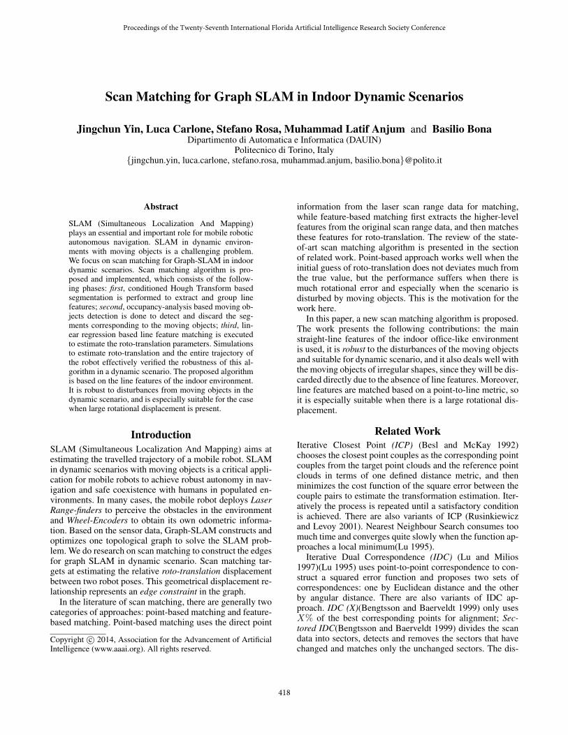
Problem FormulationGiven two sets of laser scan range data and the initial guessof their spatial geometrical relation, as illustrated in Fig. 1,the goal is to estimate the relative roto-translation through
Figure 1: Reference Scan and New Scan
matching the correspondence parts of the two sets of laserscan range data: Then the estimated roto-translation valuecould be used to construct the motion constraints as theedges of the graph for Graph-SLAM.
The new range data n(i) could be transformed to the ref-erence frame as follows:
hq(n(i)) =
[xy
]+
[cos θ − sin θsin θ cos θ
][n(i)x
n(i)y
](1)
The goal is to find the optimal solution to the minimum ofthe following equation which leads to the estimation of theroto-translation value.
J(q) = ‖r(i)c − hq(n(i)c )‖2 (2)
419
Segmentation, Moving Object Detection andRoto-Translation Estimation
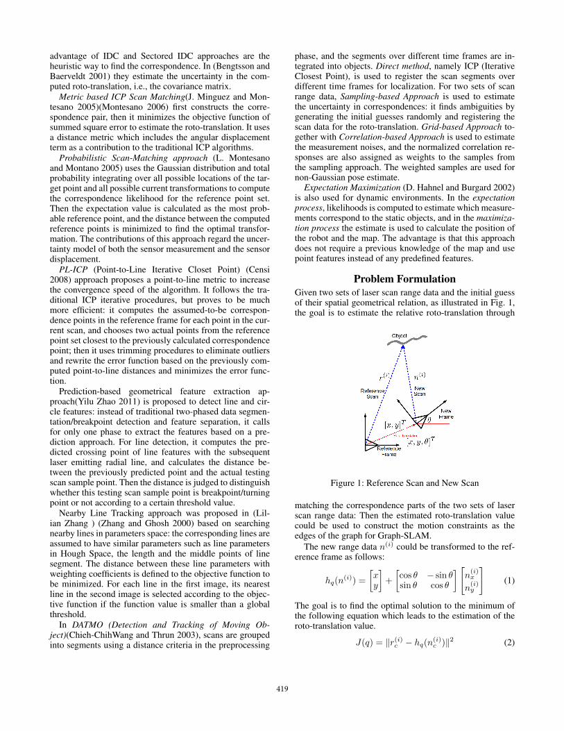
Method OverviewScan matching algorithm is proposed to solve the relativeroto-translation estimation problem in indoor dynamic envi-ronment. It consists of three phases, as is shown in Fig. 2:first, conditioned Hough Transform based segmentation isused to extract and group line-feature candidate samples intosegments; second, occupancy-analysis based moving objectsdetection is performed to detect and discard the segmentscorresponding to the moving objects; third, linear regressionbased roto-translation estimation is applied to estimate roto-translation by matching the merged independent line fea-tures.
Figure 2: Overview of the Phases in Scan-matching Algo-rithm
Conditioned Hough Transform basedSegmentation (CHTS)Segmentation is performed for the set of laser scan rangedata based on line features, and the steps are illustrated inFig. 3. Hough Transform line detection is applied to detectthe sample points which represent the small-scale line seg-ment. Hough Transform(Yilu Zhao 2011)(Richard O. Duda) is in nature a voting based approach dealing with robuststatistics contaminated with input outliers, suitable for thecase here with line features of different parameters; we addone conditioning part to the output of the previous algorithmfor anomaly detection to ensure that the line features samplepoints extracted are close in scanning index (Bishop 2006).
Figure 3: Conditioned-HT based Segmentation
Then, we use a prediction based judgment to find the break-points and perform segmentation. Inspired by (Yilu Zhao2011), the detected small line segment information is used topredict the possible coordinates of the subsequent points inindex if we assume they are on the same line. We comparethese supposed-to-be coordinates with their actual coordi-nates to check whether they are the breakpoints or not.
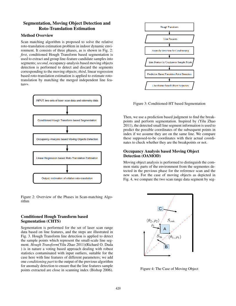
Occupancy Analysis based Moving ObjectDetection (OAMOD)Moving object analysis is performed to distinguish the com-mon static parts of the environment from the segmentes de-tected in the previous phase for the reference scan and thenew scan. For the case of moving objects as depicted inFig. 4, we compare the two scan range data segment by seg-
Figure 4: The Case of Moving Object
420
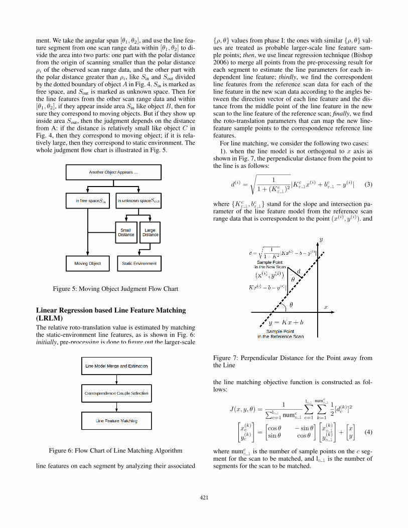
ment. We take the angular span [θ1, θ2], and use the line fea-ture segment from one scan range data within [θ1, θ2] to di-vide the area into two parts: one part with the polar distancefrom the origin of scanning smaller than the polar distanceρi of the observed scan range data, and the other part withthe polar distance greater than ρi, like Sin and Sout dividedby the dotted boundary of objectA in Fig. 4. Sin is marked asfree space, and Sout is marked as unknown space. Then forthe line features from the other scan range data and within[θ1, θ2], if they appear inside area Sin like object B, then forsure they correspond to moving objects. But if they show upinside area Sout, then the judgment depends on the distancefrom A: if the distance is relatively small like object C inFig. 4, then they correspond to moving object; if it is rela-tively large, then they correspond to static environment. Thewhole judgment flow chart is illustrated in Fig. 5.
Figure 5: Moving Object Judgment Flow Chart
Linear Regression based Line Feature Matching(LRLM)The relative roto-translation value is estimated by matchingthe static-environment line features, as is shown in Fig. 6:initially, pre-processing is done to figure out the larger-scale
Figure 6: Flow Chart of Line Matching Algorithm
line features on each segment by analyzing their associated
{ρ, θ} values from phase I: the ones with similar {ρ, θ} val-ues are treated as probable larger-scale line feature sam-ple points; then, we use linear regression technique (Bishop2006) to merge all points from the pre-processing result foreach segment to estimate the line parameters for each in-dependent line feature; thirdly, we find the correspondentline features from the reference scan data for each of theline feature in the new scan data according to the angles be-tween the direction vector of each line feature and the dis-tance from the middle point of the line feature in the newscan to the line feature of the reference scan; finally, we findthe roto-translation parameters that can map the new line-feature sample points to the correspondence reference linefeatures.
For line matching, we consider the following two cases:1). when the line model is not orthogonal to x axis as
shown in Fig. 7, the perpendicular distance from the point tothe line is as follows:
d(i) =
√1
1 + (Kcr l)
2|Kc
r lx(i) + bcr l − y(i)| (3)
where {Kcr l, b
cr l} stand for the slope and intersection pa-
rameter of the line feature model from the reference scanrange data that is correspondent to the point (x(i), y(i)). and
Figure 7: Perpendicular Distance for the Point away fromthe Line
the line matching objective function is constructed as fol-lows:
J(x, y, θ) =1∑ln l
c=1 numcn l
ln l∑c=1
numcn l∑
k=1
1
2[d(k)c ]2[
x(k)c
y(k)c
]=
[cos θ − sin θsin θ cos θ
][x(k)n l
y(k)n l
]+
[xy
](4)
where numcn l is the number of sample points on the c seg-
ment for the scan to be matched, and ln l is the number ofsegments for the scan to be matched.
421
2). when the line model is almost orthogonal to the xaxis, we just substitute the parameter set {K, b} of the non-vertical line model with the functional equivalent parameter
set { 1K,−bK} of the vertical line model. For reason of sim-
plicity, the details are not described here.
Threshold Parameters Tuning For The CombinedScan-Matching AlgorithmThere are several parameters which determine the perfor-mances of the scan-matching results. To find a balanced so-lution for all the parameters mentioned above and find a suit-able solution for roto-translation estimation, we use the Ge-netic Algorithm Optimization Toolbox in MATLAB.
Experimental VerificationTo verify the effectiveness of the scan matching algorithmfor the domestic indoor scenario, we have performed exper-iments using ROS (Robotic Operating System). For simu-lation, we use the map of Robotics Lab 10 at PolitecnicoDi Torino, together with one robot equipped with wheel en-coders and laser scanner, and three objects able to movearound. We use stage simulator to perform the experiment,as shown in Fig. 8. The proposed scan matching algorithm
Figure 8: Simulation Environment for Robotic Lab
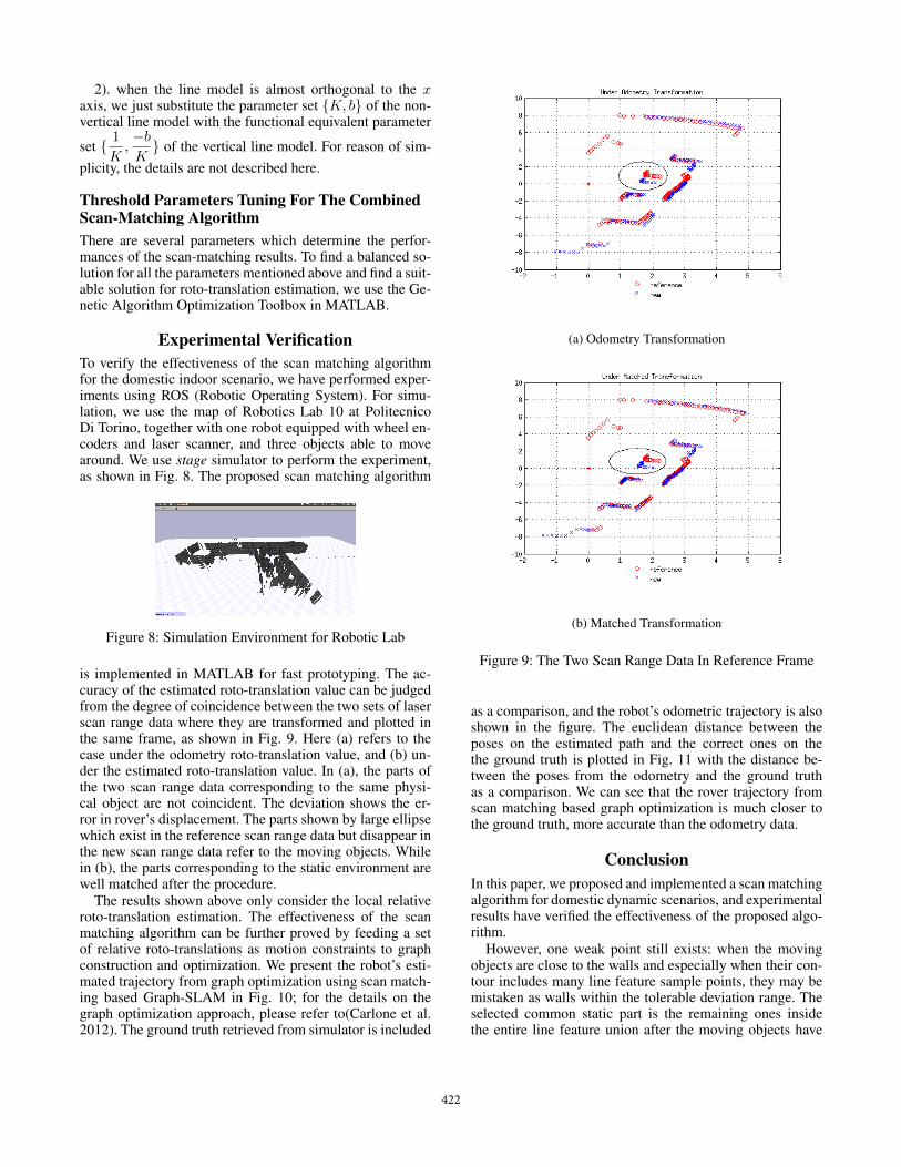
is implemented in MATLAB for fast prototyping. The ac-curacy of the estimated roto-translation value can be judgedfrom the degree of coincidence between the two sets of laserscan range data where they are transformed and plotted inthe same frame, as shown in Fig. 9. Here (a) refers to thecase under the odometry roto-translation value, and (b) un-der the estimated roto-translation value. In (a), the parts ofthe two scan range data corresponding to the same physi-cal object are not coincident. The deviation shows the er-ror in rover’s displacement. The parts shown by large ellipsewhich exist in the reference scan range data but disappear inthe new scan range data refer to the moving objects. Whilein (b), the parts corresponding to the static environment arewell matched after the procedure.
The results shown above only consider the local relativeroto-translation estimation. The effectiveness of the scanmatching algorithm can be further proved by feeding a setof relative roto-translations as motion constraints to graphconstruction and optimization. We present the robot’s esti-mated trajectory from graph optimization using scan match-ing based Graph-SLAM in Fig. 10; for the details on thegraph optimization approach, please refer to(Carlone et al.2012). The ground truth retrieved from simulator is included
(a) Odometry Transformation
(b) Matched Transformation
Figure 9: The Two Scan Range Data In Reference Frame
as a comparison, and the robot’s odometric trajectory is alsoshown in the figure. The euclidean distance between theposes on the estimated path and the correct ones on thethe ground truth is plotted in Fig. 11 with the distance be-tween the poses from the odometry and the ground truthas a comparison. We can see that the rover trajectory fromscan matching based graph optimization is much closer tothe ground truth, more accurate than the odometry data.
ConclusionIn this paper, we proposed and implemented a scan matchingalgorithm for domestic dynamic scenarios, and experimentalresults have verified the effectiveness of the proposed algo-rithm.
However, one weak point still exists: when the movingobjects are close to the walls and especially when their con-tour includes many line feature sample points, they may bemistaken as walls within the tolerable deviation range. Theselected common static part is the remaining ones insidethe entire line feature union after the moving objects have
422
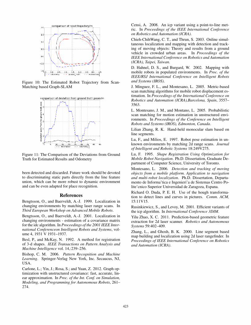
Figure 10: The Estimated Robot Trajectory from Scan-Matching based Graph-SLAM
Figure 11: The Comparison of the Deviations from GroundTruth for Estimated Results and Odometry
been detected and discarded. Future work should be devotedto discriminating static parts directly from the line featureunion, which can be more robust to dynamic environmentand can be even adapted for place recognition.
ReferencesBengtsson, O., and Baerveldt, A.-J. 1999. Localization inchanging environments by matching laser range scans. InThird European Workshop on Advanced Mobile Robots.Bengtsson, O., and Baerveldt, A.-J. 2001. Localization inchanging environments - estimation of a covariance matrixfor the idc algorithm. In Proceedings of the 2001 IEEE Inter-national Conferenceon Intelligent Robots and Systems, vol-ume 4, 1931 V 1931–1937.Besl, P., and McKay, N. 1992. A method for registrationof 3-d shapes. IEEE Transactions on Pattern Analysis andMachine Intelligence vol. 14,:239–256.Bishop, C. M. 2006. Pattern Recognition and MachineLearning. Springer-Verlag New York, Inc. Secaucus, NJ,USA.Carlone, L.; Yin, J.; Rosa, S.; and Yuan, Z. 2012. Graph op-timization with unstructured covariance: fast, accurate, lin-ear approximation. In Proc. of the Int. Conf. on Simulation,Modeling, and Programming for Autonomous Robots, 261–274.
Censi, A. 2008. An icp variant using a point-to-line met-ric. In Proceedings of the IEEE International Conferenceon Robotics and Automation (ICRA).Chieh-ChihWang, C. T., and Thrun, S. 2003. Online simul-taneous localization and mapping with detection and track-ing of moving objects: Theory and results from a groundvehicle in crowded urban areas. In Proceedings of theIEEE International Conference on Robotics and Automation(ICRA), Taipei, Taiwan.D. Hahnel, D. S., and Burgard, W. 2002. Mapping withmobile robots in populated environments. In Proc. of theIEEE/RSJ International Conference on Intelligent Robotsand Systems (IROS).J. Minguez, F. L., and Montesano, L. 2005. Metric-basedscan matching algorithms for mobile robot displacement es-timation. In Proceedings of the International Conference onRobotics and Automation (ICRA),Barcelona, Spain, 3557–3563.L. Montesano, J. M., and Montano, L. 2005. Probabilisticscan matching for motion estimation in unstructured envi-ronments. In Proceedings of the Conference on IntelligentRobots and Systems (IROS), Edmonton, Canada.Lilian Zhang, R. K. Hand-held monocular slam based online segments.Lu, F., and Milios, E. 1997. Robot pose estimation in un-known environments by matching 2d range scans. Journalof Intelligent and Robotic Systems 18:249V275.Lu, F. 1995. Shape Registration Using Optimization forMobile Robot Navigation. Ph.D. Dissertation, Graduate De-partment of Computer Science, University of Toronto.Montesano, L. 2006. Detection and tracking of movingobjects from a mobile platform. Application to navigationand multi-robot localization. Ph.D. Dissertation, Departa-mento de Informa’tica e Ingenieri’a de Sistemas Centro Po-lite’cnico Superior Universidad de Zaragoza, Espana.Richard O. Duda, P. E. H. Use of the hough transforma-tion to detect lines and curves in pictures. Comm. ACM,15:11V15.Rusinkiewicz, S., and Levoy, M. 2001. Efficient variants ofthe icp algorithm. In International Conference 3DIM.Yilu Zhao, X. C. 2011. Prediction-based geometric featureextraction for 2d laser scanner. Robotics and AutonomousSystems 59:402–409.Zhang, L., and Ghosh, B. K. 2000. Line segment basedmap building and localization using 2d laser rangefinder. InProceedings of IEEE International Conference on Roboticsand Automation (ICRA).
423
Recommended


![The Design of a Fully Autonomous Robot System for …...HectorSLAM is a 2D SLAM system based on robust scan matching [5]. This module focused on the real-time estimation of the robot](https://img.dokumen.tips/doc/110x75/5f1a956862015c47df5bcf14/the-design-of-a-fully-autonomous-robot-system-for-hectorslam-is-a-2d-slam-system.jpg)