CAT-SDF-2006(1)
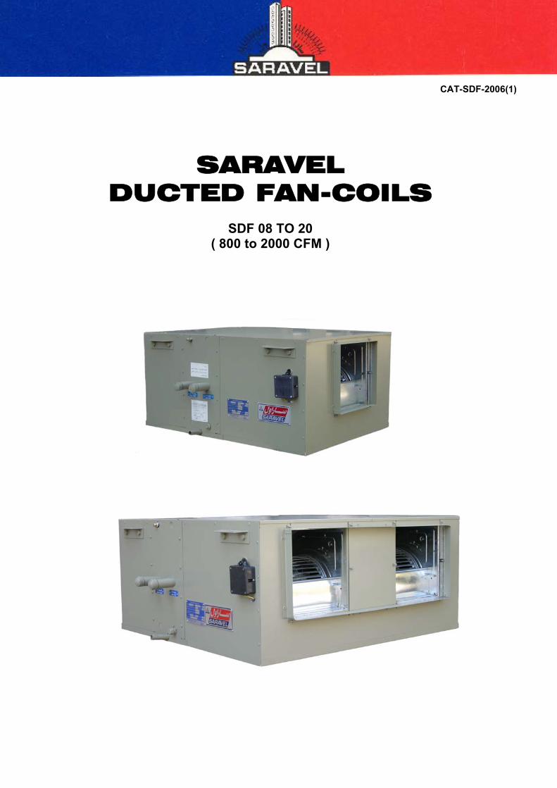
SARAVEL
DUCTED FAN-COILS
SDF 08 TO 20 ( 800 to 2000 CFM )
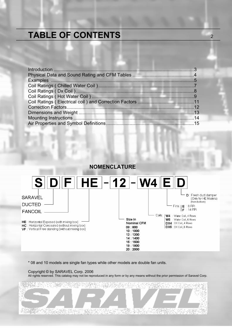
TABLE OF CONTENTS 2 Introduction ...........................................................................................................3 Physical Data and Sound Rating and CFM Tables ...............................................4 Examples .............................................................................................................5 Coil Ratings ( Chilled Water Coil ) .........................................................................7 Coil Ratings ( Dx Coil ) ..........................................................................................8 Coil Ratings ( Hot Water Coil ) ..............................................................................9 Coil Ratings ( Electrical coil ) and Correction Factors ...........................................11 Correction Factors .................................................................................................12 Dimensions and Weight ........................................................................................13 Mounting Instructions ............................................................................................14 Air Properties and Symbol Definitions ...................................................................15
NOMENCLATURE
* 08 and 10 models are single fan types while other models are double fan units. Copyright © by SARAVEL Corp. 2006 All rights reserved. This catalog may not be reproduced in any form or by any means without the prior permission of Saravel Corp.
FEATURES & BENEFITS SARAVEL ducted Fan-Coil units are designed to deliver reliable conditioned air in a wide range of capacities. With delivery rates of 800 to 3000 CFM these units can meet the air conditioning demands of a variety of multi room applications such as apartments, office buildings, hotels, and hospitals. For cooling applications, units are available with capacities ranging from 20 to 100 kBtu/hr and for heating units with capacities of 60 to 200 kBtu/hr at standard conditions (80°F DB, 67°F WB) can be utilized. With 3 different models and seven basic sizes in each model along with the choice of vertical or horizontal types, the wide selection range offers considerable design versatility. EASE OF INSTALLATION & MAINTENANCE Horizontal models can be used in cabinet (Exposed) or furred-in (Concealed) applications. Vertical models are built only in exposed free standing models. The low height dimension associated with the horizontal types facilitates easy installation within double ceilings or concealed locations. Supply air duct collar simplifies field connection to new or existing supply ductwork. Mounting Brackets on each side of the unit allow swift suspension from the ceiling. All wiring and piping connections are located at accessible locations on the unit. Removable bottom panels permit full width access to the mixing box and blower units. Motor-blower unit can be removed in order to expose the entering face of the coil for cleaning purposes. The following design features are incorporated in the construction of SARAVEL ducted Fan-Coil units: CABINET All cabinets are constructed of 1.25 mm galvanized steel sheet with additional paint coating. Panels are insulated with 10 mm polyethylene insulation panel. COILS Coils are constructed of 5/8 inch O.D. copper tubes with waffled and rippled edge aluminum or copper fins mechanically bonded to the tubes. All coils are leak tested under water with 325 Psig air in accordance with ANSI/ASHRAE 15 Safety Code for Mechanical Refrigeration. The coils for hot water applications are identical to chilled water coils available in 4 or 6 rows. All DX coils are evacuated and backfilled with 5 Psig dry nitrogen prior to shipment. Electrical coils could also be mounted on any unit. They shall be protected against overheating. FILTERS Standard filter is removable 1" aluminum mesh washable filter.
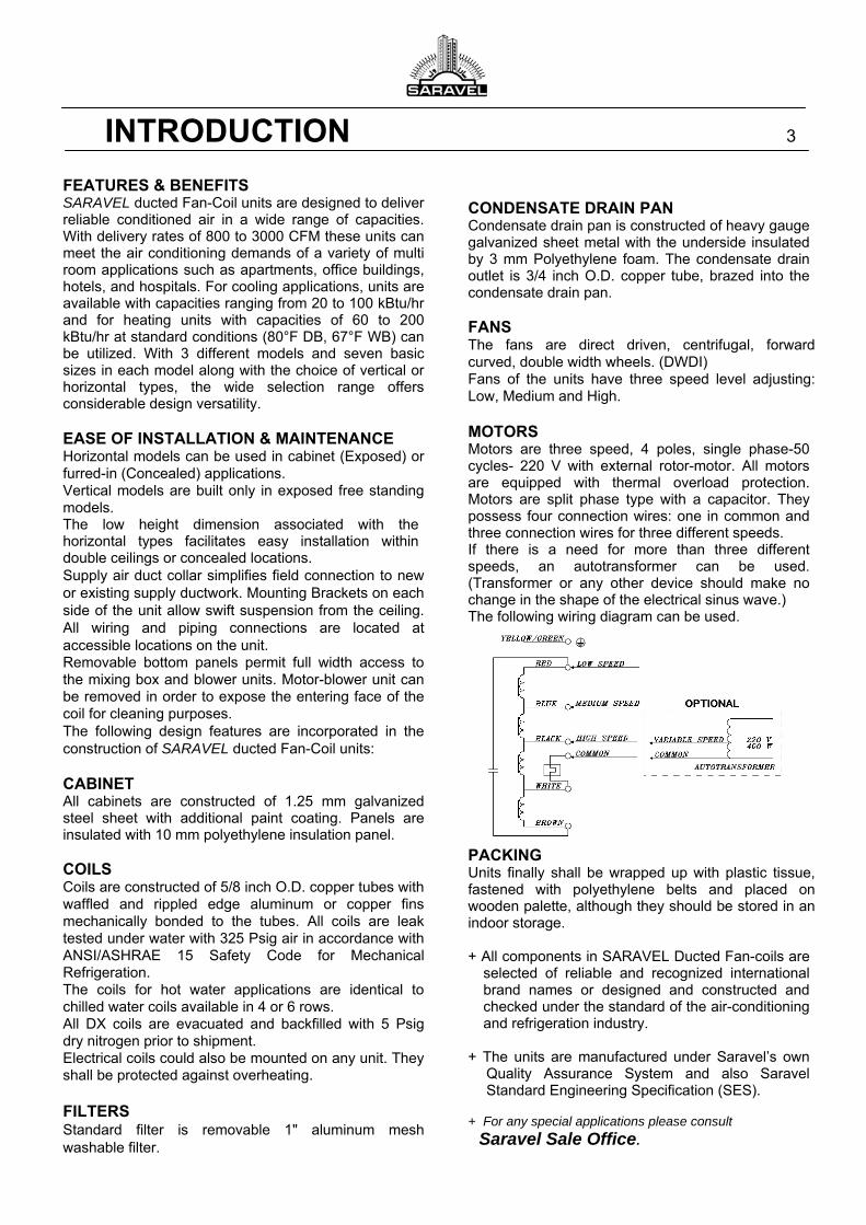
CONDENSATE DRAIN PAN Condensate drain pan is constructed of heavy gauge galvanized sheet metal with the underside insulated by 3 mm Polyethylene foam. The condensate drain outlet is 3/4 inch O.D. copper tube, brazed into the condensate drain pan. FANS The fans are direct driven, centrifugal, forward curved, double width wheels. (DWDI) Fans of the units have three speed level adjusting: Low, Medium and High. MOTORS Motors are three speed, 4 poles, single phase-50 cycles- 220 V with external rotor-motor. All motors are equipped with thermal overload protection. Motors are split phase type with a capacitor. They possess four connection wires: one in common and three connection wires for three different speeds. If there is a need for more than three different speeds, an autotransformer can be used. (Transformer or any other device should make no change in the shape of the electrical sinus wave.) The following wiring diagram can be used. PACKING Units finally shall be wrapped up with plastic tissue, fastened with polyethylene belts and placed on wooden palette, although they should be stored in an indoor storage. + All components in SARAVEL Ducted Fan-coils are
selected of reliable and recognized international brand names or designed and constructed and checked under the standard of the air-conditioning and refrigeration industry.
+ The units are manufactured under Saravel’s own
Quality Assurance System and also Saravel Standard Engineering Specification (SES).
+ For any special applications please consult
Saravel Sale Office.
INTRODUCTION 3
0.0 0.5 0.0 0.1 0.2 0.3 0.4 0.5 0.0 0.58 FPI 650 600 1030 1010 990 970 940 910 1300 115014 FPI 630 580 1000 975 955 930 900 870 1250 10508 FPI 750 650 1150 1140 1130 1110 1080 1050 1550 135014 FPI 730 630 1130 1120 1100 1070 1040 1000 1450 12508 FPI 1260 1120 1880 1825 1775 1725 1670 1580 2200 185014 FPI 1240 1080 1750 1700 1650 1570 1490 1400 2000 16508 FPI 1270 1150 1950 1920 1870 1810 1760 1700 2400 205014 FPI 1260 1120 1860 1810 1750 1700 1640 1550 2200 18008 FPI 1280 1170 2020 1980 1930 1890 1830 1770 2550 215014 FPI 1270 1150 1940 1890 1840 1790 1730 1680 2350 20008 FPI 1450 1260 2280 2240 2200 2160 2090 2020 2900 250014 FPI 1420 1230 2210 2170 2110 2050 1990 1880 2750 23008 FPI 1470 1300 2300 2280 2250 2210 2170 2100 3050 270014 FPI 1450 1270 2270 2230 2200 2140 2080 2020 2900 2450
CFM with 4 Row Coils
14
18
20
LowModel
12
External Pres. Drop
08
10
External Pressure
HighSpacing
MediumExternal Pressure (inch H2O)
16
0.0 0.5 0 0.1 0.2 0.3 0.4 0.5 0.0 0.58 FPI 640 580 1000 965 940 910 885 860 1230 1030
14 FPI 630 550 930 910 880 860 830 800 1110 9208 FPI 720 630 1130 1110 1090 1060 1030 1000 1430 1200
14 FPI 700 600 1100 1060 1030 1000 960 900 1380 10708 FPI 1230 1050 1730 1680 1600 1530 1450 1370 2020 1600
14 FPI 1170 1000 1530 1470 1400 1340 1270 1200 1720 13008 FPI 1250 1100 1830 1780 1730 1680 1600 1500 2190 1770
14 FPI 1220 1050 1700 1620 1560 1490 1410 1340 1920 15408 FPI 1270 1130 1920 1870 1810 1760 1700 1630 2330 1937
14 FPI 1250 1100 1780 1740 1690 1620 1550 1470 2100 17008 FPI 1400 1220 2200 2140 2080 2020 1940 1840 2700 2200
14 FPI 1370 1170 2050 2000 1920 1840 1770 1650 2400 18608 FPI 1450 1250 2250 2210 2180 2110 2050 1980 2870 2400
14 FPI 1400 1220 2170 2110 2050 2000 1910 1810 2600 2150
Model External Pressure External Pressure (inch H2O)
10
08
CFM with 6 Row CoilsHigh
SpacingLow
External Pressure
Medium
20
14
16
12
18
BlowerWater DX Water DX Type (Watt) RPM (Amper*) Low Medium High
08 800 2.05 1.64 500 400 10 1 × 9/7 350 450~1425 0.85~3.2 56 60 64
10 1000 2.45 2.05 600 500 10 1 × 9/9 350 450~1425 0.85~3.2 51 57 60
12 1200 2.87 2.87 700 700 10 2 × 9/7 350 450~1425 0.85~3.2 59 63 67
14 1400 3.27 2.87 800 700 10 2 × 9/7 350 450~1425 0.85~3.2 59 63 67
16 1600 3.68 3.28 900 800 10 2 × 9/7 350 450~1425 0.85~3.2 59 63 67
18 1800 4.30 3.90 1050 950 10 2 × 9/9 350 450~1425 0.85~3.2 54 60 63
20 2000 4.91 4.51 1200 1100 10 2 × 9/9 350 450~1425 0.85~3.2 54 60 63
ModelNominal
CFM
Coil
Tube High
No. ×
Blower & motor
Motor (each)
Physical Data and Sound RatingsSound Ratings (dB)
( Sound Pressure Level at 1 m ) Face area (ft²) Finned Length (mm)
UNIT CHARACTERISTICS 4
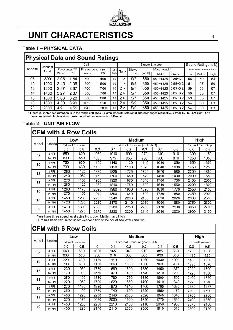
Table 1 – PHYSICAL DATA * Electrical motor consumption is in the range of 0.85 to 3.2 amp when its rotational speed changes respectively from 450 to 1425 rpm. Any
selection should be based on maximum electrical current i.e. 3.2 amp.
Table 2 – UNIT AIR FLOW
Fans have three speed level adjustings: Low, Medium and High. CFM has been calculated under wet condition of the coil at sea level condition.
Example (General):
Unit Selection Procedure:
1- Determining exact unit airflow: Enter Table 2 on page 4. Select the nearest Model.
2- Calculate the face velocity, FV using the face area, FA from Table 1 on page 4:
FA
CFM=FV
3- Determine the appropriate correction factors.
(Table 7,8,9 and 10 on page 11) (Figures 1,2 and 3 on page 12)
(Interpolation is allowed when needed.)
4- Correct the specified total capacity:
Factors Correction
Load Sensible or Total RequiredQ
5- Enter the tables of ratings with Q
(Tables 3,4,5 and 6 on pages 7~11) and check out for the selected model. (Repeat steps 1 to 5 to find the suitable unit.)
6- Find the actual ratings
(Net real working capacity in the location and conditions of the project.)
Factors Correction × Raings Table =Qactual (There is one exception:
5C Is always applied to both Total and Sensible load but
when5C is used only for correcting the wet bulb temperature (not
water temp. or evaporating temp.), it is applied only to Total load.)
7- a) Determining water flow rate (GPM) b) Determining leaving air dry bulb (LDB) c) Determining leaving air enthalpy )H( 2
(By having 1H from Table 11 on page15)
d) Determining leaving air wet bulb temp. (LWB)
a) TΔ × 500
Q = GPM Water T
b) LDB)-(CFM)(EDB 08.1=Qs
c) )HCFM)(H( 5.4=Q 21T -
d) Interpolating in Table 11 (by having 2H )
for leaving air wet bulb temp. (LWB).
Example 1: Summer System Requirement
Given: Air Flow Rate …………………………………… 1000 CFM External Static Pressure ……………………..………. 0.3” Total / Sensible Load …………….……..… 27 / 19 kBtu/hr Altitude of Installation ….…………………....…….. 1250m Entering Air Temperature (EAT) ….... 80°F DB/ 70°F WB Entering/Leaving Water Temperature (EWT/LWT)... 45/55°F
Solution: 1- Table 2 on page 4: Based on airflow, selecting Model 10:
4 Rows, 8 FPI: Air flow = 1110 CFM (Selection is based on “Medium” condition in order
to account for additional capacity.)
2- FPM 453=ft 2.45
CFM 1110=
FA
CFM=FV 2
3- Correction factors: (T.7 P.11) Total load correction factor = 06.1=CT
(T.7 P.11) Sensible load correction factor = 07.1=CS
(T.8 P.11) Altitude correction factor = 0.95=C2
(T.9 P.11) Fin material correction factor = 0.1=C3
(T.10 P.11) Refrigerant correction factor = 1.0 =C4
(F.1 P.12) Air wet bulb correction factor = 1.15 =C 5
4- Correcting the required load
kBtu/hr 3.23=15.1×95.0×06.1
kBtu/hr 27=
C×C×C
Load Total=Q
52TT
2SS C×C
Load ensibleS=Q = kBtu/hr 7.18=
95.0×07.1
kBtu/hr 19
(For correcting the wet bulb temp. only, 5C is applied just to Total load.)
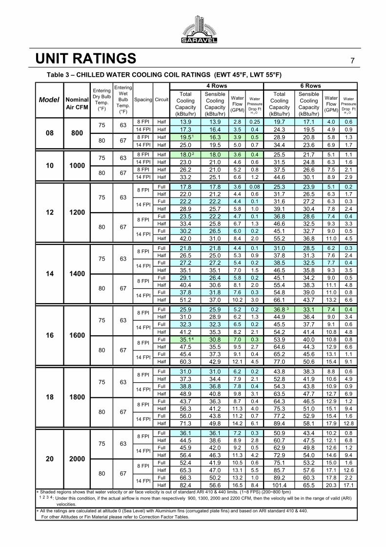
5- Entering the table 3 on page 7 Model 10: 80°F DB/ 67°F WB, 4 rows, 8 FPI: TQ : 26.2 kBtu/hr > 23.3 kBtu/hr (required)
SQ : 21.0 kBtu/hr > 18.7 kBtu/hr (required)
So SDF-10 (4 rows, 8FPI, Half cir.) is approved.
6- Actual ratings: Total: kBtu/hr 3.30=95.0×15.1×06.1× 26.2=QT
Sensible: kBtu/hr 3.21=95.0×07.1× 21.0=QS
7- a) Water flow GPM 1.6=10×500
30300=GPM
b) F° 62.2 =1110 × 08.1
21300 - 80=LDB
c) Btu/lb 8.30=1110 × 5.4
30300 - 9.36=H2
d) On Table 11 on page 15 by 2H and Altitude of 1250m
LWB = 63.1 °F
(Because of the correction factor approximations, the exact temperature sometimes is obtained a little different. The LWB is about 62°F in this case.)
EXAMPLES 5
Example 2: Summer System Requirement (DX Coil)
Given: Air Flow Rate …………………………………… 1600 CFM External Static Pressure ……………………..………. 0.2” Total / Sensible Load …………….……..… 42 / 31 kBtu/hr Altitude of Installation ….…………………....…….. 1250m Entering Air Temperature (EAT) …... 80°F DB/ 67°F WB Evaporating Temperature …………….…………….. 50°F Solution: 1- Table 2 on page 4: Based on airflow, selecting Model 12:
4 Rows, 14 FPI: Air flow = 1650 CFM (Selection is based on “Medium” condition in
order to account for additional capacity.)
2- FPM 575=ft 2.87
CFM 1650=
FA
CFM=FV 2
3- Correction factors: (Interpolation is required) (T.7 P.11) Total load correction factor = 19.1=CT
(T.7 P.11) Sensible load correction factor = 25.1=CS
(T.8 P.11) Altitude correction factor = 0.95=C2
(T.9 P.11) Fin material correction factor = 0.1=C3
(T.10 P.11) Refrigerant correction factor = 1.0 =C4
(F.3 P.12) Evaporating Temp. corr. fac. = 0.85 =C 5
4- Correcting the required load
kBtu/hr 7.43=85.0×95.0×19.1
kBtu/hr 42=
C×C×C
Load Total=Q
52TT
52SS C×C×C
Load ensibleS=Q = kBtu/hr 7.30=
85.0×95.0×25.1
kBtu/hr 31
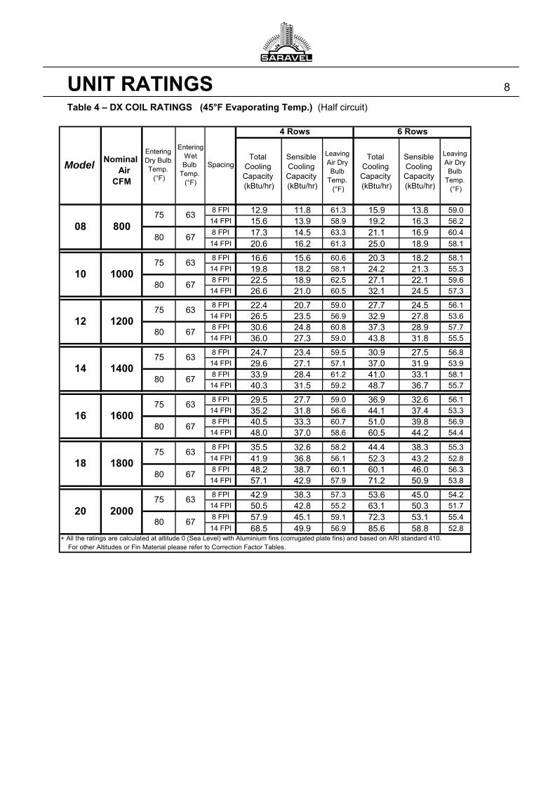
5- Entering the table 4 on page 8 Model 12: 80°F DB/ 67°F WB, 4 rows, 14 FPI: TQ : 36.0 kBtu/hr < 43.7 kBtu/hr (required)
SQ : 27.3 kBtu/hr < 30.7 kBtu/hr (required)
So SDF-12 (4 rows, 14FPI and Half cir. failed.) Repeating steps 1 to 5:
For SDF-12 (6 rows, 8FPI and Half cir.): TQ : 37.3 kBtu/hr < 44.4 kBtu/hr (required)
SQ : 28.9 kBtu/hr > 31.5 kBtu/hr (required)
So SDF-12 (6 rows, 8FPI and Half cir.) failed. SDF-12 (6 rows, 14FPI and Half cir.) failed. SDF-14 (4 rows, 14FPI and Half cir.) failed. SDF-14 (6 rows, 8FPI and Half cir.) failed.
TQ : 48.7 kBtu/hr > 45.2 kBtu/hr (required)
SQ : 36.7 kBtu/hr > 32.3 kBtu/hr (required)
SDF-14 (6 rows, 14FPI and Half cir.) is approved.
(The actual air flow is 1560 cfm at Medium rotational speed of the fan.)
6- Actual ratings for SDF-14 (6 rows, 14FPI & Half cir.):
kBtu/hr 2.45=95.0×85.0×15.1× 7.48=QT
kBtu/hr 3.35=95.0×85.0×19.1× 36.7=Qs
7- a) Water flow GPM 0.9=10×500
45200=GPM
b) F° 59.0 =1560 × 08.1
1000 × 35.3 - 80=LDB
c) Btu/lb 7.27=1560 × 5.4
1000 × 2.45 - 13.34=H2
d) On Table 11 by 2H and Altitude of 1250m
LWB =59.1 °F
(Because of the correction factor approximations, the exact temperature sometimes is obtained a little different. The LWB is about 59°F in this case.)
Example 3: Winter System Requirement (Hot water Coil)
Given: Air Flow Rate …………………………………… 1800 CFM External Static Pressure ……………………..………. 0.3” Heating Load ………………….….………....… 160 kBtu/hr Altitude of Installation ….…………………....………… 0m Entering Air Temperature (EAT) ……………….. 80°F DB Entering/Leaving Water Temperature ……….. 180/160°F
Solution: 1- Table 2 on page 4: Based on airflow, selecting Model 16:
4 Rows, 14 FPI: Air flow = 1790 CFM (Selection is based on “Medium” condition in
order to account for additional capacity.)
2- FPM 486=ft 3.68
CFM 1790=
FA
CFM=FV 2
3- Correction factors: (T.7 P.11) Total load correction factor = 07.1=CT
(T.8 P.11) Altitude correction factor = 0.1=C2
(T.9 P.11) Fin material correction factor = 0.1=C3
4- Correcting the required load
kBtu/hr 5.149=0.1×0.1×07.1
kBtu/hr 160=
C×C×C
Load Total=Q
32TT
5- Entering the table 5 on page 10 Model 16: 80°F DB, 4 rows, 14 FPI: TQ : 149.8 kBtu/hr > 149.5 kBtu/hr (required)
So SDF-16 (4 rows, 14FPI & Half cir. is approved.
6- Actual ratings for SDF-16 (4 rows, 14FPI & Half cir.): kBtu/hr 3.160=0.1×0.1×07.1× 8.149=QT
7- a) Water flow GPM 0.16=20×500
160300=GPM
b) F° 162.9 =1790 × 08.1
160300 +80=LDB
EXAMPLES 6
Total Cooling Capacity (kBtu/hr)
Sensible Cooling Capacity (kBtu/hr)
Water Flow
(GPM)
Water Pressure Drop Ft
Total Cooling Capacity (kBtu/hr)
Sensible Cooling Capacity (kBtu/hr)
Water Flow
(GPM)
Water Pressure Drop Ft
8 FPI Half 13.9 13.9 2.8 0.25 19.7 17.1 4.0 0.6
14 FPI Half 17.3 16.4 3.5 0.4 24.3 19.5 4.9 0.9
8 FPI Half 19.5 16.3 3.9 0.5 28.9 20.8 5.8 1.3
14 FPI Half 25.0 19.5 5.0 0.7 34.4 23.6 6.9 1.7
8 FPI Half 18.0 18.0 3.6 0.4 25.5 21.7 5.1 1.114 FPI Half 23.0 21.0 4.6 0.6 31.5 24.8 6.3 1.68 FPI Half 26.2 21.0 5.2 0.8 37.5 26.6 7.5 2.1
14 FPI Half 33.2 25.1 6.6 1.2 44.6 30.1 8.9 2.9
Full 17.8 17.8 3.6 0.08 25.3 23.9 5.1 0.2Half 22.0 21.2 4.4 0.6 31.7 26.5 6.3 1.7Full 22.2 22.2 4.4 0.1 31.6 27.2 6.3 0.3Half 28.9 25.7 5.8 1.0 39.1 30.4 7.8 2.4Full 23.5 22.2 4.7 0.1 36.8 28.6 7.4 0.4Half 33.4 25.8 6.7 1.3 46.6 32.5 9.3 3.3Full 30.2 26.5 6.0 0.2 45.1 32.7 9.0 0.5Half 42.0 31.0 8.4 2.0 55.2 36.8 11.0 4.5
Full 21.8 21.8 4.4 0.1 31.0 28.5 6.2 0.3Half 26.5 25.0 5.3 0.9 37.8 31.3 7.6 2.4Full 27.2 27.2 5.4 0.2 38.5 32.5 7.7 0.4Half 35.1 35.1 7.0 1.5 46.5 35.8 9.3 3.5Full 29.1 26.4 5.8 0.2 45.1 34.2 9.0 0.5Half 40.4 30.6 8.1 2.0 55.4 38.3 11.1 4.8Full 37.8 31.8 7.6 0.3 54.8 39.0 11.0 0.8Half 51.2 37.0 10.2 3.0 66.1 43.7 13.2 6.6
Full 25.9 25.9 5.2 0.2 36.8 33.1 7.4 0.4Half 31.0 28.9 6.2 1.3 44.9 36.4 9.0 3.4Full 32.3 32.3 6.5 0.2 45.5 37.7 9.1 0.6
Half 41.2 35.3 8.2 2.1 54.2 41.4 10.8 4.8Full 35.1 30.8 7.0 0.3 53.9 40.0 10.8 0.8Half 47.5 35.5 9.5 2.7 64.6 44.3 12.9 6.6Full 45.4 37.3 9.1 0.4 65.2 45.6 13.1 1.1Half 60.3 42.9 12.1 4.5 77.0 50.6 15.4 9.1
Full 31.0 31.0 6.2 0.2 43.8 38.3 8.8 0.6Half 37.3 34.4 7.9 2.1 52.8 41.9 10.6 4.9Full 38.8 36.8 7.8 0.4 54.3 43.8 10.9 0.9Half 48.9 40.8 9.8 3.1 63.5 47.7 12.7 6.9Full 43.7 36.3 8.7 0.4 64.3 46.5 12.9 1.2Half 56.3 41.2 11.3 4.0 75.3 51.0 15.1 9.4Full 56.0 43.8 11.2 0.7 77.2 52.9 15.4 1.6Half 71.3 49.8 14.2 6.1 89.4 58.1 17.9 12.8
Full 36.1 36.1 7.2 0.3 50.9 43.4 10.2 0.8Half 44.5 38.6 8.9 2.8 60.7 47.5 12.1 6.8Full 45.9 42.0 9.2 0.5 62.9 49.8 12.6 1.2Half 56.4 46.3 11.3 4.2 72.9 54.0 14.6 9.4Full 52.4 41.9 10.5 0.6 75.1 53.2 15.0 1.6Half 65.3 47.0 13.1 5.5 85.7 57.6 17.1 12.6Full 66.3 50.2 13.2 1.0 89.2 60.3 17.8 2.2Half 82.4 56.6 16.5 8.4 101.4 65.5 20.3 17.1
20
6780
2000
63
14 FPI
8 FPI
8 FPI
8 FPI
14 FPI
67
678 FPI
75
75
8 FPI
63
63
14 FPI
8 FPI
14 FPI
14 FPI
1000
6780
67
14 1400
10
80
80
75
16
80
1600
75
14 FPI
8 FPI
14 FPI
75 63
6 Rows
Circuit
Entering Wet Bulb
Temp. (°F)
4 Rows
Spacing
Nominal Air CFM
Entering Dry Bulb Temp.
(°F)
6780
120012
8 FPI
Model
08 800
63
14 FPI
678 FPI
14 FPI
75 638 FPI
14 FPI
velocities.
180018
For other Altitudes or Fin Material please refer to Correction Factor Tables.
+ Shaded regions shows that water velocity or air face velocity is out of standard ARI 410 & 440 limits. (1~8 FPS) (200~800 fpm)
: Under this condition, if the actual airflow is more than respectively 900, 1300, 2000 and 2200 CFM, then the velocity will be in the range of valid (ARI)
+ All the ratings are calculated at altitude 0 (Sea Level) with Aluminium fins (corrugated plate fins) and based on ARI standard 410 & 440.
6375
80
OH 2 OH 2
1
2
3
4
1 2 3 4
UNIT RATINGS 7
Table 3 – CHILLED WATER COOLING COIL RATINGS (EWT 45°F, LWT 55°F)
Total Cooling Capacity (kBtu/hr)
Sensible Cooling Capacity (kBtu/hr)
Leaving Air Dry Bulb
Temp. (°F)
Total Cooling Capacity (kBtu/hr)
Sensible Cooling Capacity (kBtu/hr)
Leaving Air Dry Bulb
Temp. (°F)
8 FPI 12.9 11.8 61.3 15.9 13.8 59.014 FPI 15.6 13.9 58.9 19.2 16.3 56.2
8 FPI 17.3 14.5 63.3 21.1 16.9 60.4
14 FPI 20.6 16.2 61.3 25.0 18.9 58.1
8 FPI 16.6 15.6 60.6 20.3 18.2 58.114 FPI 19.8 18.2 58.1 24.2 21.3 55.38 FPI 22.5 18.9 62.5 27.1 22.1 59.614 FPI 26.6 21.0 60.5 32.1 24.5 57.3
8 FPI 22.4 20.7 59.0 27.7 24.5 56.114 FPI 26.5 23.5 56.9 32.9 27.8 53.68 FPI 30.6 24.8 60.8 37.3 28.9 57.714 FPI 36.0 27.3 59.0 43.8 31.8 55.5
8 FPI 24.7 23.4 59.5 30.9 27.5 56.814 FPI 29.6 27.1 57.1 37.0 31.9 53.98 FPI 33.9 28.4 61.2 41.0 33.1 58.114 FPI 40.3 31.5 59.2 48.7 36.7 55.7
8 FPI 29.5 27.7 59.0 36.9 32.6 56.114 FPI 35.2 31.8 56.6 44.1 37.4 53.38 FPI 40.5 33.3 60.7 51.0 39.8 56.914 FPI 48.0 37.0 58.6 60.5 44.2 54.4
8 FPI 35.5 32.6 58.2 44.4 38.3 55.3
14 FPI 41.9 36.8 56.1 52.3 43.2 52.88 FPI 48.2 38.7 60.1 60.1 46.0 56.314 FPI 57.1 42.9 57.9 71.2 50.9 53.8
8 FPI 42.9 38.3 57.3 53.6 45.0 54.214 FPI 50.5 42.8 55.2 63.1 50.3 51.7
8 FPI 57.9 45.1 59.1 72.3 53.1 55.4
14 FPI 68.5 49.9 56.9 85.6 58.8 52.8+ All the ratings are calculated at altitude 0 (Sea Level) with Aluminium fins (corrugated plate fins) and based on ARI standard 410.
8018
10
63
6375
180075
67
80
120075
67
1600
8014
63
Model
Nominal
Air CFM
Entering Dry Bulb Temp.
(°F)
16
63
6 Rows
Entering Wet Bulb
Temp. (°F)
4 Rows
Spacing
67
08
63
6780
75
80
63
67
67
75
6375
200020
For other Altitudes or Fin Material please refer to Correction Factor Tables.
800
1000
80
12
67
751400
80
UNIT RATINGS 8
Table 4 – DX COIL RATINGS (45°F Evaporating Temp.) (Half circuit)
Total Heating Capacity kBtu/hr
Leaving Air Dry Bulb
Temp. (°F)
Water Flow GPM
Water Pressure Drop Ft
Total Heating Capacity kBtu/hr
Leaving Air Dry Bulb
Temp. (°F)
Water Flow GPM
Water Pressure Drop Ft
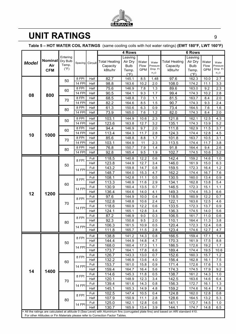
8 FPI Half 82.7 145.1 8.5 1.48 97.6 162.3 10.0 2.714 FPI Half 98.8 163.6 10.2 2.0 108.0 174.2 11.1 3.38 FPI Half 75.6 146.9 7.8 1.3 89.6 163.0 9.2 2.314 FPI Half 90.5 164.1 9.3 1.7 99.4 174.3 10.2 2.88 FPI Half 68.5 148.8 7.0 1.1 81.5 163.7 8.4 2.014 FPI Half 82.2 164.6 8.5 1.5 90.7 174.3 9.3 2.48 FPI Half 61.3 150.6 6.3 0.9 73.4 164.5 7.6 1.614 FPI Half 73.9 165.0 7.6 1.2 82.0 174.3 8.4 2.0
8 FPI Half 103.1 144.9 10.6 2.3 121.8 162.1 12.5 4.314 FPI Half 123.6 163.8 12.7 3.2 135.1 174.3 13.9 5.28 FPI Half 94.4 146.9 9.7 2.0 111.8 162.9 11.5 3.714 FPI Half 113.4 164.3 11.7 2.8 124.3 174.4 12.8 4.58 FPI Half 85.6 148.8 8.8 1.7 101.8 163.7 10.5 3.114 FPI Half 103.1 164.9 11 2.3 113.5 174.4 11.7 3.88 FPI Half 76.8 150.7 7.9 1.4 91.8 164.4 9.4 2.614 FPI Half 92.8 165.4 9.5 1.9 102.7 174.5 10.6 3.2
Full 118.5 140.8 12.2 0.6 142.4 159.2 14.6 1.0Half 123.8 144.9 12.7 3.4 146.0 161.9 15.0 6.3Full 143.2 159.8 14.7 0.8 159.5 172.3 16.4 1.2Half 148.7 164.0 15.3 4.7 162.2 174.4 16.7 7.6Full 108.1 142.8 11.1 0.5 130.5 160.0 13.4 0.9Half 113.3 146.9 11.6 2.9 134.1 162.8 13.8 5.4Full 130.9 160.4 13.5 0.7 146.5 172.3 15.1 1.1Half 136.4 164.6 14.0 4.1 149.3 174.4 15.3 6.6Full 97.6 144.9 10.0 0.4 118.5 160.9 12.2 0.7Half 102.8 148.8 10.6 2.4 122.1 163.6 12.5 4.6Full 118.6 160.9 12.2 0.6 133.5 172.3 13.7 0.9Half 124.1 165.1 12.8 3.4 136.3 174.5 14.0 5.6Full 87.2 146.9 9.0 0.3 106.5 161.7 11.0 0.6Half 92.3 150.8 9.5 2.0 110.1 164.4 11.3 3.8Full 106.3 161.5 10.9 0.5 120.4 172.3 12.4 0.8Half 111.8 165.7 11.5 2.8 123.4 174.6 12.7 4.7
Full 138.8 141.2 14.3 0.8 166.5 159.4 17.1 1.4Half 144.4 144.9 14.8 4.7 170.3 161.9 17.5 8.8Full 168.0 160.4 17.3 1.1 186.5 172.6 19.2 1.7Half 173.7 164.1 17.8 6.6 189.4 174.4 19.5 10.6Full 126.7 143.3 13.0 0.7 152.6 160.3 15.7 1.2Half 132.2 146.9 13.6 4.0 156.4 162.8 16.1 7.5Full 153.7 161.0 15.8 0.9 171.4 172.6 17.6 1.5Half 159.4 164.7 16.4 5.6 174.3 174.5 17.9 9.2Full 114.6 145.3 11.8 0.5 138.7 161.2 14.3 1.0Half 120.1 148.9 12.3 3.4 142.5 163.6 14.6 6.4Full 139.4 161.6 14.3 0.8 156.3 172.7 16.1 1.3Half 145.1 165.3 14.9 4.8 159.2 174.6 16.4 7.8Full 102.5 147.4 10.5 0.4 124.8 162.0 12.8 0.8Half 107.9 150.9 11.1 2.8 128.6 164.5 13.2 5.3Full 125.0 162.1 12.8 0.6 141.1 172.7 14.5 1.0Half 130.7 165.9 13.4 3.9 144.1 174.7 14.8 6.5
+ All the ratings are calculated at altitude 0 (Sea Level) with Aluminium fins (corrugated plate fins) and based on ARI standard 410. For other Altitudes or Fin Materials please refer to Correction Factor Tables.
12
508 FPI
14 FPI
8 FPI
1200
14 FPI
8 FPI
14 FPI
8 FPI
6014 FPI
80
708 FPI
10
80
8 FPI
14 FPI80
14 1400
14 FPI
80070
60
1000
80
70
50
4 Rows
Spacing
50
8 FPI
Circuit
608 FPI
14 FPI
70
14 FPI
50
60
Model
Nominal
Air CFM
Entering Dry Bulb Temp.
(°F)
08
6 Rows
OH 2OH 2
UNIT RATINGS 9
Table 5 – HOT WATER COIL RATINGS (same cooling coils with hot water ratings) (EWT 180°F, LWT 160°F)
Total Heating Capacity kBtu/hr
Leaving Air Dry Bulb
Temp. (°F)
Water Flow GPM
Water Pressure Drop Ft
Total Heating Capacity kBtu/hr
Leaving Air Dry Bulb
Temp. (°F)
Water Flow GPM
Water Pressure Drop Ft
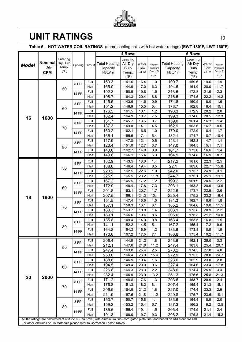
Full 159.3 141.6 16.4 1.0 190.7 159.6 19.6 1.9Half 165.0 144.9 17.0 6.3 194.6 161.9 20.0 11.7Full 192.8 160.9 19.8 1.5 213.6 172.8 21.9 2.3
Half 198.7 164.3 20.4 8.8 216.5 174.5 22.2 14.2Full 145.5 143.6 14.6 0.9 174.8 160.5 18.0 1.6Half 151.2 146.9 15.5 5.4 178.7 162.8 18.4 10.1Full 176.5 161.5 18.1 1.2 196.3 172.9 20.2 2.0Half 182.4 164.9 18.7 7.5 199.3 174.6 20.5 12.3Full 131.7 145.7 13.5 0.7 159.0 161.4 16.3 1.4Half 137.3 149.0 14.1 4.5 162.9 163.6 16.7 8.5Full 160.2 162.1 16.5 1.0 179.0 172.9 18.4 1.7Half 166.1 165.5 17.1 6.4 182.1 174.7 18.7 10.4Full 117.9 147.8 12.1 0.6 143.1 162.3 14.7 1.1Half 123.4 151.0 12.7 3.7 147.0 164.5 15.1 7.1Full 143.8 162.7 14.8 0.9 161.7 173.0 16.6 1.4Half 149.8 166.1 15.4 5.3 164.9 174.8 16.9 8.7
Full 182.9 143.5 18.8 1.4 217.2 161.0 22.3 2.5Half 188.6 146.4 19.4 8.5 22.1 163.0 22.7 15.8Full 220.2 162.5 22.6 1.9 242.0 173.7 24.9 3.1Half 225.9 165.5 23.2 11.8 244.7 175.1 25.1 19.1Full 167.2 145.5 17.2 1.2 199.2 161.9 20.5 2.2Half 172.9 148.4 17.8 7.3 203.1 163.8 20.9 13.6Full 201.8 163.1 20.7 1.7 222.6 173.7 22.9 2.6Half 207.5 166.1 21.3 10.1 225.4 175.2 23.2 16.4Full 151.5 147.4 15.6 1.0 181.3 162.7 18.6 1.8Half 157.1 150.3 16.1 6.1 185.2 164.6 19.0 11.5Full 183.3 163.7 18.8 1.4 203.1 173.8 20.9 2.2Half 189.1 166.6 19.4 8.6 206.0 175.3 21.2 14.0Full 135.8 149.4 14.0 0.8 163.4 163.5 16.8 1.5Half 141.1 152.2 14.5 5.1 167.2 165.4 17.2 9.6Full 164.8 164.3 16.9 1.2 183.6 173.8 18.9 1.9Half 170.6 167.2 17.5 7.1 186.6 175.4 19.2 11.7
Full 206.4 144.9 21.2 1.8 243.6 162.1 25.0 3.3Half 212.1 147.6 21.8 11.2 247.4 163.8 25.4 20.7Full 247.4 163.8 25.4 2.5 270.2 174.3 27.8 4.0Half 253.0 166.4 26.0 15.4 272.9 175.5 28.0 24.7Full 188.8 146.9 19.4 1.6 223.6 162.9 23.0 2.8Half 194.5 149.4 20.0 9.6 227.4 164.6 23.4 17.8Full 226.8 164.3 23.3 2.2 248.6 174.4 25.5 3.4Half 232.4 166.9 23.9 13.2 251.3 175.6 25.8 21.3Full 171.2 148.8 17.6 1.3 203.6 163.7 20.9 2.4Half 176.8 151.3 18.2 8.1 207.4 165.4 21.3 15.1Full 206.5 164.9 21.2 1.8 227.0 174.4 23.3 2.9
Half 211.9 167.5 21.8 11.2 229.8 175.7 23.6 18.1Full 153.7 150.7 15.8 1.1 183.6 164.4 18.9 2.0Half 159.2 153.2 16.4 6.7 187.3 166.2 19.2 12.5
Full 185.6 165.4 19.1 1.5 205.4 174.5 21.1 2.4
Half 191.3 168.0 19.7 9.3 208.2 175.8 21.4 15.2
8 FPI
6 Rows
+ All the ratings are calculated at altitude 0 (Sea Level) with Aluminium fins (corrugated plate fins) and based on ARI standard 410.
8 FPI
50
8 FPI
14 FPI
8 FPI
50
8 FPI
Spacing CircuitModel
Nominal
Air CFM
16
14 FPI
14 FPI
80
1600
608 FPI
14 FPI
708 FPI
4 Rows
8 FPI
Entering Dry Bulb Temp.
(°F)
80
188 FPI
14 FPI
8 FPI
14 FPI
14 FPI70
60
14 FPI
508 FPI
14 FPI
608 FPI
14 FPI
20
70
For other Altitudes or Fin Materials please refer to Correction Factor Tables.
1800
14 FPI
80
14 FPI
2000
OH 2 OH 2
UNIT RATINGS 10
Table 5 – HOT WATER COIL RATINGS (same cooling coils with hot water ratings) (EWT 180°F, LWT 160°F)
300 350 375 400 425 450 475 500 525 550 600 650Total 0.82 0.94 0.98 1.01 1.05 1.08 1.12 1.15 1.18 1.20 1.26 1.32
Sensible 0.83 0.92 0.97 1.01 1.05 1.10 1.15 1.19 1.23 1.27 1.34 1.42
Total 0.83 0.92 0.96 0.99 1.03 1.06 1.09 1.13 1.16 1.19 1.24 1.30Sensible 0.80 0.90 0.94 0.99 1.04 1.07 1.12 1.16 1.20 1.23 1.31 1.38
Total 0.81 0.90 0.93 0.97 1.01 1.04 1.07 1.10 1.13 1.16 1.22 1.28Sensible 0.78 0.88 0.92 0.97 1.01 1.05 1.09 1.13 1.17 1.21 1.28 1.35
Total 0.80 0.88 0.92 0.96 1.00 1.03 1.06 1.09 1.13 1.16 1.22 1.27Sensible 0.77 0.87 0.91 0.96 1.00 1.04 1.08 1.12 1.16 1.20 1.26 1.33
Total 0.79 0.88 0.91 0.95 0.99 1.03 1.06 1.09 1.12 1.15 1.21 1.27Sensible 0.77 0.86 0.90 0.94 0.99 1.03 1.07 1.10 1.14 1.18 1.25 1.32
Total 0.81 0.90 0.94 0.98 1.01 1.05 1.09 1.12 1.16 1.18 1.25 1.30Sensible 0.79 0.88 0.93 0.97 1.01 1.06 1.10 1.14 1.18 1.21 1.29 1.36
Total 0.82 0.91 0.95 0.99 1.04 1.07 1.11 1.14 1.17 1.21 1.27 1.33Sensible 0.80 0.90 0.94 0.99 1.02 1.08 1.12 1.16 1.20 1.24 1.31 1.39
14
16
18
20
08
10
12
ModelFace Velocity (FPM)Correction
type
Correction Factor
11.05
Fin Material
AlCu
Correction Factor
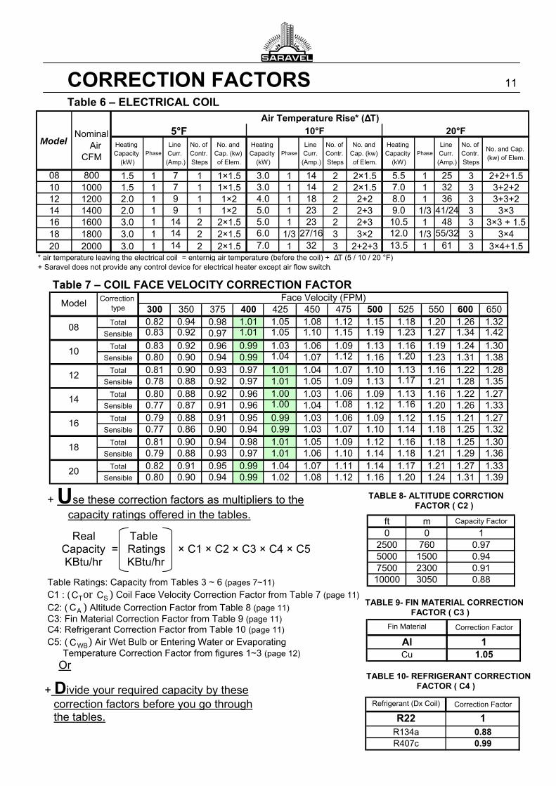
10.880.99
Refrigerant (Dx Coil)
R22R134aR407c
1.5 1 7 1 1×1.5 3.0 1 14 2 2×1.5 5.5 1 25 3 2+2+1.510 1000 1.5 1 7 1 1×1.5 3.0 1 14 2 2×1.5 7.0 1 32 3 3+2+212 1200 2.0 1 9 1 1×2 4.0 1 18 2 2+2 8.0 1 36 3 3+3+214 1400 2.0 1 9 1 1×2 5.0 1 23 2 2+3 9.0 1/3 41/24 3 3×316 1600 3.0 1 14 2 2×1.5 5.0 1 23 2 2+3 10.5 1 48 3 3×3 + 1.518 1800 3.0 1 14 2 2×1.5 6.0 1/3 27/16 3 3×2 12.0 1/3 55/32 3 3×420 2000 3.0 1 14 2 2×1.5 7.0 1 32 3 2+2+3 13.5 1 61 3 3×4+1.5
* air temperature leaving the electrical coil = enternig air temperature (before the coil) + ΔT (5 / 10 / 20 °F)+ Saravel does not provide any control device for electrical heater except air flow switch.
No. and Cap. (kw) of Elem.
08 800
Heating Capacity
(kW)
Phase
Line Curr. (Amp.)
No. of Contr. Steps
Phase
Line Curr. (Amp.)
No. of Contr. Steps
No. and Cap. (kw) of Elem.
No. and Cap. (kw) of Elem.
Heating Capacity
(kW)
Model
Nominal Air CFM
Air Temperature Rise* (ΔT)
5°F 10°F 20°FHeating Capacity
(kW)
Phase
Line Curr. (Amp.)
No. of Contr. Steps
TABLE 8- ALTITUDE CORRCTION FACTOR ( C2 )
TABLE 10- REFRIGERANT CORRECTION FACTOR ( C4 )
ft m Capacity Factor
0 0 12500 760 0.975000 1500 0.947500 2300 0.9110000 3050 0.88
CORRECTION FACTORS 11
Table 6 – ELECTRICAL COIL
Table 7 – COIL FACE VELOCITY CORRECTION FACTOR
+ Use these correction factors as multipliers to the capacity ratings offered in the tables.
Real Table Capacity = Ratings × C1 × C2 × C3 × C4 × C5 KBtu/hr KBtu/hr
Table Ratings: Capacity from Tables 3 ~ 6 (pages 7~11) C1 : ( or ) Coil Face Velocity Correction Factor from Table 7 (page 11) C2: ( ) Altitude Correction Factor from Table 8 (page 11) C3: Fin Material Correction Factor from Table 9 (page 11) C4: Refrigerant Correction Factor from Table 10 (page 11) C5: ( ) Air Wet Bulb or Entering Water or Evaporating Temperature Correction Factor from figures 1~3 (page 12)
Or
TABLE 9- FIN MATERIAL CORRECTION FACTOR ( C3 )
TC SC
WBC
AC
+ Divide your required capacity by these correction factors before you go through the tables.
1- Fan Speed Control a) Manual
The units are provided with a manual three-fan speed control. (Unit or wall mounted)
b) Automatic The fans could be switched ON/OFF while has been set to one of the three different working condition (Low, Medium or High) by a single-stage thermostat. (Not included) A Four-stage thermostat (including OFF) could also control the fan speed automatically. (Not included)
2- Water Control Valves a) Manual
By having hand-operated valves installed in the supply or return water circuit, each unit could be isolated from the whole water system. (Not included)
b) Automatic Valves could be either solenoid or motor operated. Two or Three way valves also could be used. (Not included) Thermostat could control a solenoid valve or also a two-way or Three-way water valve to set the suitable flow rate of water. (Not included)
3- Electrical Coil Safety Temperature Control
An optional control device could turn off the electrical coil if its temperature rises above a defined limit. (Not included)
CORRECTION FACTORS 12
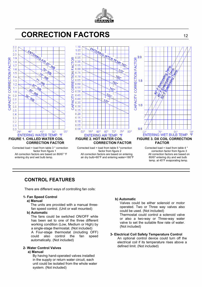
FIGURE 1. CHILLED WATER COIL FIGURE 2. HOT WATER COIL FIGURE 3. DX COIL CORRECTION CORRECTION FACTOR CORRECTION FACTOR FACTOR
Corrected load = load from table 3 * correction Corrected load = load from table 5 *correction Corrected load = load from table 4 * factor from figure 1 factor from figure 2 correction factor from figure 3
All correction factors are based on 80/67 °F All correction factors are based on entering All correction factors are based on entering dry and wet bulb temp. air dry bulb=60°F and entering water=180°F 80/67 entering dry and wet bulb
temp. at 45°F evaporating temp.
CONTROL FEATURES There are different ways of controlling fan coils:
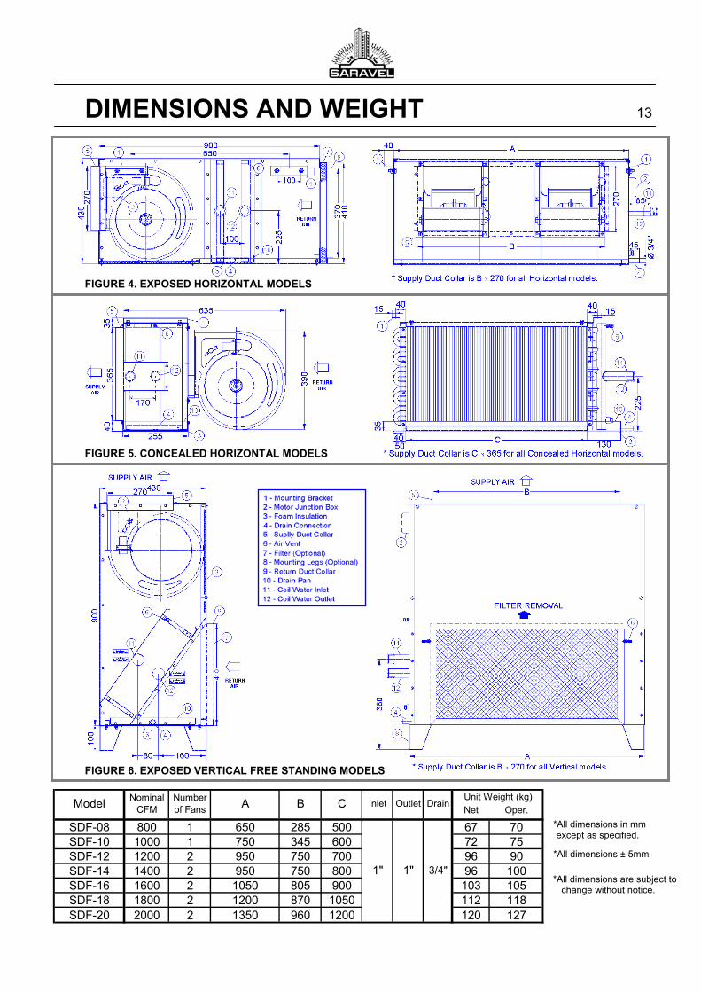
*All dimensions are subject to change without notice.
Net Oper.
SDF-08 800 1 650 285 500 67 70SDF-10 1000 1 750 345 600 72 75SDF-12 1200 2 950 750 700 96 90SDF-14 1400 2 950 750 800 96 100SDF-16 1600 2 1050 805 900 103 105SDF-18 1800 2 1200 870 1050 112 118SDF-20 2000 2 1350 960 1200 120 127
1" 1" 3/4"
DrainUnit Weight (kg)
ModelNominal
CFMNumber of Fans A B C Inlet Outlet
DIMENSIONS AND WEIGHT 13
FIGURE 4. EXPOSED HORIZONTAL MODELS FIGURE 5. CONCEALED HORIZONTAL MODELS FIGURE 6. EXPOSED VERTICAL FREE STANDING MODELS
*All dimensions in mm except as specified.
*All dimensions ± 5mm
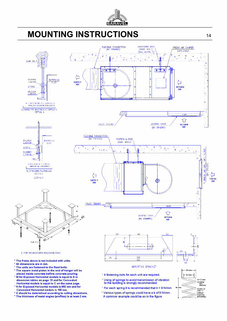
MOUNTING INSTRUCTIONS 14
01000(ft)
2000(ft)
3000(ft)
4000(ft)
5000(ft)
0 315(m) 625(m) 940(m) 1250(m) 1560(m)
35 13.01 13.18 13.36 13.54 13.74 13.9436 13.44 13.62 13.8 14 14.20 14.4137 13.87 14.06 14.25 14.46 14.67 14.8938 14.32 14.51 14.71 14.92 15.14 15.3739 14.77 14.97 15.18 15.4 15.63 15.8740 15.23 15.44 15.66 15.89 16.12 16.3741 15.7 15.92 16.14 16.38 16.63 16.8942 16.17 16.42 16.64 16.88 17.14 17.4143 16.66 16.89 17.14 17.39 17.66 17.9444 17.15 17.39 17.65 17.92 18.20 18.4945 17.65 17.91 18.17 18.45 18.74 19.0446 18.16 18.43 18.7 18.99 19.29 19.6147 18.68 18.96 19.25 19.55 19.86 20.1948 19.21 19.5 19.8 20.11 20.44 20.7849 19.75 20.05 20.36 20.69 21.03 21.3850 20.30 20.61 20.94 21.27 21.63 22.0051 20.86 21.19 21.52 21.87 22.24 22.6252 21.44 21.77 22.12 22.49 22.87 23.2753 22.02 22.37 22.73 23.11 23.51 23.9254 22.62 22.98 23.36 23.75 24.16 24.5955 23.22 23.6 23.99 24.4 24.83 25.2856 23.84 24.24 24.64 25.07 25.51 25.9857 24.48 24.88 25.31 25.75 26.21 26.6958 25.12 25.55 25.99 26.44 26.92 27.4259 25.78 26.22 26.68 27.15 27.65 28.1760 26.46 26.92 27.39 27.88 28.40 28.9461 27.15 27.62 28.11 28.62 29.16 29.7262 27.85 28.34 28.85 29.39 29.94 30.5263 28.57 29.08 29.61 30.16 30.74 31.3564 29.31 29.84 30.39 30.96 31.56 32.1965 30.06 30.61 31.18 31.77 32.39 33.0566 30.83 31.4 31.99 32.61 33.25 33.9367 31.62 32.21 32.82 33.46 34.13 34.8368 32.42 33.03 33.67 34.33 35.03 35.7569 33.25 33.88 34.54 35.32 35.95 36.7070 34.09 34.74 35.43 36.14 36.89 37.6771 34.95 35.63 36.34 37.08 37.85 38.6772 35.83 36.54 37.27 38.04 38.84 39.6973 36.74 37.46 38.23 39.02 39.86 40.7374 37.66 38.42 39.2 40.03 40.89 41.8075 38.61 39.39 40.21 41.06 41.96 42.9076 39.57 40.39 41.23 42.12 43.05 44.0277 40.57 41.41 42.29 43.21 44.17 45.1878 41.58 42.45 43.36 44.32 45.32 46.3679 42.62 43.53 44.47 45.46 46.49 47.5880 43.69 44.62 45.6 46.63 47.70 48.8381 44.78 45.75 46.76 47.83 48.94 50.1082 45.9 46.91 47.95 49.05 50.21 51.4283 47.04 48.09 49.18 50.32 51.51 52.7684 48.22 49.3 50.43 51.61 52.85 54.1585 49.43 50.33 51.71 52.94 54.22 55.57
Enthalpy of Air (Btu/lb)
WetBulb
Temp.oF
Altitude Density Press.
lb/ft3 in. w.g
0 0 0.0750 29.92500 (160) 0.0739 29.381000 (310) 0.0728 28.851500 (460) 0.0718 28.332000 (610) 0.0707 27.822500 (770) 0.0697 27.313000 (920) 0.0686 26.823500 (1070) 0.0676 26.324000 (1220) 0.0666 25.844500 (1380) 0.0656 25.365000 (1530) 0.0646 24.905500 (1680) 0.0637 24.436000 (1830) 0.0627 23.986500 (1990) 0.0617 23.537000 (2140) 0.0608 23.097500 (2290) 0.0599 22.658000 (2440) 0.0590 22.228500 (2600) 0.0580 21.809000 (2750) 0.0571 21.399500 (2900) 0.0563 20.98
10000 (3050) 0.0554 20.58
AltitudeFeet (meters)
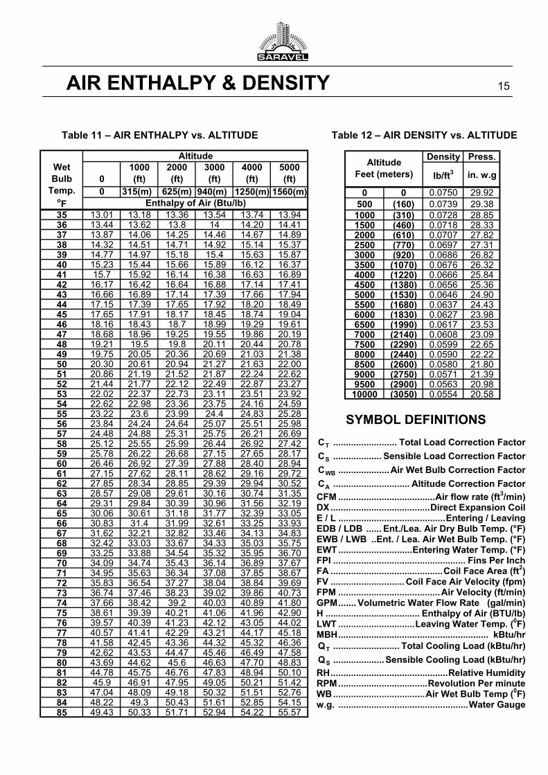
AIR ENTHALPY & DENSITY 15
Table 11 – AIR ENTHALPY vs. ALTITUDE Table 12 – AIR DENSITY vs. ALTITUDE
SYMBOL DEFINITIONS
TC ......................... Total Load Correction Factor
SC ................... Sensible Load Correction Factor
WBC .................... Air Wet Bulb Correction Factor
AC .............................. Altitude Correction Factor
CFM ...................................... Air flow rate (ft3/min) DX ....................................... Direct Expansion Coil E / L .......................................... Entering / Leaving EDB / LDB ...... Ent./Lea. Air Dry Bulb Temp. (°F) EWB / LWB .. Ent. / Lea. Air Wet Bulb Temp. (°F) EWT ............................. Entering Water Temp. (°F) FPI .................................................... Fins Per Inch FA ............................................ Coil Face Area (ft2) FV ............................. Coil Face Aِir Velocity (fpm) FPM ........................................ Air Velocity (ft/min) GPM ....... Volumetric Water Flow Rate (gal/min) H ..................................... Enthalpy of Air (BTU/lb) LWT .............................. Leaving Water Temp. (0F) MBH ........................................................... kBtu/hr
TQ .......................... Total Cooling Load (kBtu/hr)
SQ .................... Sensible Cooling Load (kBtu/hr)
RH .............................................. Relative Humidity RPM ................................... Revolution Per minute WB .................................... Air Wet Bulb Temp (0F) w.g. ................................................... Water Gauge
SARAVEL CORP. Sep. 2006
Manufacturer reserves the right to make changes in design and construction, without notice.
(Head Office) No. 43, North Sheikh Bahai Avenue, Tehran 19917 , IRAN Tel: (+98-21) 88046921 (6 lines) Fax: (+98-21) 88046920
E-Mail: [email protected] Site: http://www.Saravel.com
Recommended


