SAMIL POWERExpert for PV Grid-tied Inverters
TM
SP-SR-D-V1.2-EN
SolarRiver-D PV Grid-tied Inverter
Product ManualEnglish


Copyright Declaration
The copyright of this manual belongs to Samil Power Co., Ltd. Any corporation or individual should not plagiarize, partially copy or fully copy it (including software, etc.), and should not reproduce or distribute it in any form or by any means. All rights reserved. Samil Power reserves the right of final interpretation. This manual changes according to user’s or customer’s feedback. Please check our website at www.samilpower.com for the latest version.
01

02
CONTENTS
4 Operation Mode ................................................................................................................. 10
03
1.1 Scope Of Validity ..................................................................................................................
3.1 New Features .......................................................................................................................
3.2 Electrical Block Diagram ..........................................................................................................
3.3 Principle Description ..............................................................................................................
3.4 Protection Function ................................................................................................................
3.5 Terminals of Inverter ............................................................................................................
3.6 Dimension ...........................................................................................................................
3.7 Product Label .......................................................................................................................
1.2 Target Group ........................................................................................................................1.3 Important Safety Information ................................................................................................ 1.4 Symbols Used ...................................................................................................................... 1.5 Symbols on the Inverter ........................................................................................................1.6 Important Safety Instructions .................................................................................................
1 Notes On This Manual ......................................................................................................... 5
7
8
555556
8
9
9
9
10
2 Grid-tied System Brief Introduction .................................................................................... 7
73 Introduction of SolarRiver-D Series Inverter ......................................................................
5.7.1 Announcements ..........................................................................................................
5.7.2 PV Array Connection Types ...........................................................................................
5.7.3 Connection Steps of DC Connector .................................................................................
5.7.4 Assembly Steps of AC Connector ...................................................................................
5.7.5 Grounding ..................................................................................................................
5.7.6 Connection of Communication .......................................................................................
5.1 Installation Process .............................................................................................................
5.2 Packaging List .....................................................................................................................
5.3 Safety Instruction ................................................................................................................
5.4 Installation Precaution .........................................................................................................
5.5 Installation Tools ..................................................................................................................
5.6 Installation Steps ................................................................................................................
5.7 Connections of the PV Power System ......................................................................................
11
11
12
12
14
16
14
16
16
17
18
20
20
115 Installation ........................................................................................................................
6.1 Safety Inspection ................................................................................................................
6.2 Start Inverter ......................................................................................................................
6.3 Interface Setting .................................................................................................................
21
21
21
216 Run the Inverter ...............................................................................................................
7.1 Control and Display Panel .....................................................................................................
7.2 Interface Setting ..................................................................................................................
7.2.2 Main Menu ..................................................................................................................
7.2.3 Instantaneous Data ......................................................................................................
7.2.1 Home Interface ...........................................................................................................
7.2.4 Historical Data ...........................................................................................................
23
24
24
24
24
25
237 Operation .........................................................................................................................
04
10.1 Decommissioning Steps ......................................................................................................
10.2 Package ............................................................................................................................
10.3 Storage ............................................................................................................................
10.4 Disposal ...........................................................................................................................
41
41
41
41
4010 Decommissioning ............................................................................................................
11.1 Input (DC) ........................................................................................................................
11.2 Output (AC) .......................................................................................................................
11.3 Efficiency ..........................................................................................................................
11.4 General Data .....................................................................................................................
41
42
42
42
4111 Technical Data ................................................................................................................
4312 Guarantees ....................................................................................................................
8.1 Communication Interface .....................................................................................................
8.2 Communication Mode ............................................................................................................
8.2.2 RS485 Communication .................................................................................................
8.2.3 WIFI Communication ....................................................................................................
8.2.1 Ethernet Communication ..............................................................................................
31
31
31
35
36
318 Communication and Monitoring .......................................................................................
9.1 Troubleshooting ..................................................................................................................
9.2 Daily Maintenance ................................................................................................................
39
40
399 Troubleshooting and Maintenance ...................................................................................
7.2.5 Event List ....................................................................................................................
7.2.6 Settings ...................................................................................................................
25
257.3 CEI 0-21 Settings ................................................................................................................ 25
Notes on This Manual
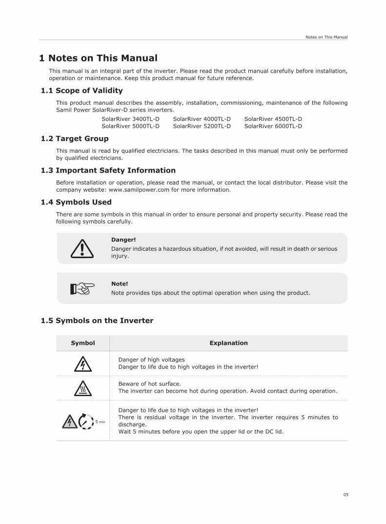
Danger!
Danger indicates a hazardous situation, if not avoided, will result in death or serious injury.
Note!
Note provides tips about the optimal operation when using the product.
05
ExplanationSymbol
5 min
Danger to life due to high voltages in the inverter!There is residual voltage in the inverter. The inverter requires 5 minutes to discharge. Wait 5 minutes before you open the upper lid or the DC lid.
Beware of hot surface.The inverter can become hot during operation. Avoid contact during operation.
Danger of high voltagesDanger to life due to high voltages in the inverter!
1 Notes on This ManualThis manual is an integral part of the inverter. Please read the product manual carefully before installation, operation or maintenance. Keep this product manual for future reference.
1.1 Scope of Validity
This product manual describes the assembly, installation, commissioning, maintenance of the following Samil Power SolarRiver-D series inverters.
SolarRiver 3400TL-D SolarRiver 4000TL-D SolarRiver 4500TL-DSolarRiver 5000TL-D SolarRiver 5200TL-D SolarRiver 6000TL-D
1.2 Target Group
This manual is read by qualified electricians. The tasks described in this manual must only be performed by qualified electricians.
1.3 Important Safety Information
Before installation or operation, please read the manual, or contact the local distributor. Please visit the company website: www.samilpower.com for more information.
1.4 Symbols Used
There are some symbols in this manual in order to ensure personal and property security. Please read the following symbols carefully.
1.5 Symbols on the Inverter
Notes on This Manual
Ensure input DC voltage ≤ Max.DC voltage .Over voltage may cause permanent damage to inverter or other losses, which will not be included in warranty! This chapter contains important safety and operating instructions. Read and keep this Operation Guide for future reference.
Authorized service personnel must disconnect both AC and DC power from the SolarRiver-D Series inverter before any maintenance or cleaning or working on any circuits.
06
1.6 Important Safety Instructions
When using the product, please remember the information below to avoid the fire, lightning or other personal injury:
● Before using the SolarRiver-D Series inverter, read all instructions and cautionary markings on the SolarRiver-D Series inverter, and all appropriate sections of this guide.
● Recommend the attachments sold by Samil Power, otherwise may result in a risk of fire, electric shock, or injury to persons.
● To avoid a risk of fire and electric shock, make sure that existing wiring is in good condition and wire is not undersized. Do not operate the SolarRiver-D Series inverter with damaged or substandard wire.
● Do not disassemble the SolarRiver-D Series inverter. It contains no user-serviceable parts. See warrantyfor instructions on obtaining service. Attempting to service the SolarRiver-D series inverter by yourself may result in a risk of electric shock or fire and will void your warranty.
● To reduce the risk of electric shock, authorized service personnel must disconnect both AC and DC power from the SolarRiver-D series inverter before any maintenance or cleaning or working on anycircuits connected to the SolarRiver-D Series inverter.
● Keep away from flammable, explosive materials to avoid fire disaster.
● The product should be installed away from humid or corrosive substance.
● To avoid electric shock accident, please do not disassemble the inverter because there are high-voltage capacitances installed inside the inverter.
● To reduce the risk of short-circuits, authorized service personnel must use insulated tools when installingor working with this equipment.
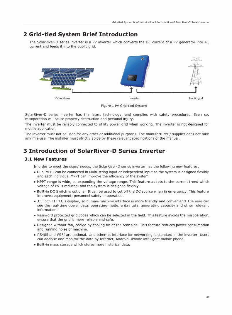
Figure 1 PV Grid-tied System
07
Grid-tied System Brief Introduction & Introduction of SolarRiver-D Series Inverter
PV modules Inverter Public grid
3 Introduction of SolarRiver-D Series Inverter3.1 New Features
In order to meet the users’ needs, the SolarRiver-D series inverter has the following new features;
● Dual MPPT can be connected in Multi-string input or independent input so the system is designed flexibly and each individual MPPT can improve the efficiency of the system.
● MPPT range is wide, so expanding the voltage range. This feature adapts to the current trend which voltage of PV is reduced, and the system is designed flexibly.
● Built-in DC Switch is optional. It can be used to cut off the DC source when in emergency. This feature improves equipment, personnel safety in operation.
● 3.5 inch TFT LCD display, so human-machine interface is more friendly and convenient! The user can see the real-time power data, operating mode, a day total generating capacity and other relevant information!
● Password protected grid codes which can be selected in the field. This feature avoids the misoperation, ensure that the grid is more reliable and safe.
● Designed without fan, cooled by cooling fin at the rear side. This feature reduces power consumption and running noise of machine.
● RS485 and WIFI are optional,and ethernet interface for networking is standard in the inverter. Users can analyse and monitor the data by Internet, Android, iPhone intelligent mobile phone.
● Built-in mass storage which stores more historical data.
2 Grid-tied System Brief IntroductionThe SolarRiver-D series inverter is a PV inverter which converts the DC current of a PV generator into AC current and feeds it into the public grid.
SolarRiver-D series inverter has the latest technology, and complies with safety procedures. Even so, misoperation will cause property destruction and personal injury.
The inverter must be reliably connected to utility power grid when working. The inverter is not designed for mobile application.
The inverter must not be used for any other or additional purposes. The manufacturer / supplier does not take any mis-use. The installer must strictly abide by these relevant specifications of the manual.
Introduction of SolarRiver-D Series Inverter
08
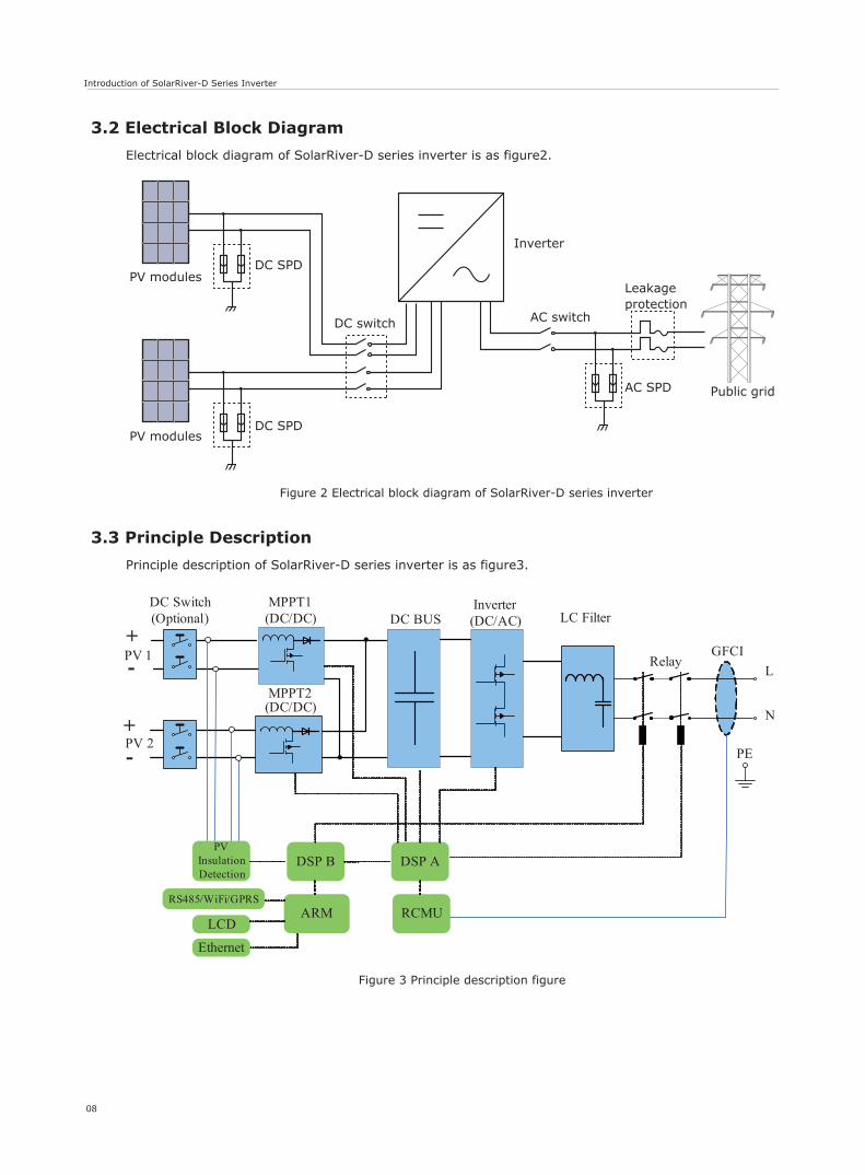
Figure 2 Electrical block diagram of SolarRiver-D series inverter
Figure 3 Principle description figure
AC switch
Leakageprotection
Inverter
AC SPD Public grid
DC switch
DC SPD
DC SPDPV modules
PV modules
N
-
PVInsulationDetection
DSP B DSP A
PE
RCMUARM
-+
LCD
Ethernet
MPPT1 (DC/DC)
MPPT2(DC/DC)
DC BUS Inverter(DC/AC) LC Filter
RelayGFCIPV 1
PV 2
+
RS485/WiFi/GPRS
DC Switch(Optional)
L
N
3.2 Electrical Block Diagram
Electrical block diagram of SolarRiver-D series inverter is as figure2.
3.3 Principle Description
Principle description of SolarRiver-D series inverter is as figure3.
Introduction of SolarRiver-D Series Inverter
09
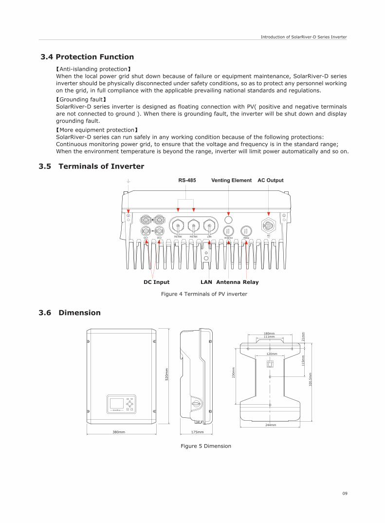
3.6 Dimension
Figure 4 Terminals of PV inverter
AC Output
AntennaLAN Relay
RS-485 Venting Element
DC Input
LANRS-485 RS-485 ACDC1 DC2 Antenna Relay
M16
x1.5
M16
x1.5
3.4 Protection Function
【Anti-islanding protection】When the local power grid shut down because of failure or equipment maintenance, SolarRiver-D series inverter should be physically disconnected under safety conditions, so as to protect any personnel working on the grid, in full compliance with the applicable prevailing national standards and regulations.
【Grounding fault】SolarRiver-D series inverter is designed as floating connection with PV( positive and negative terminals are not connected to ground ). When there is grounding fault, the inverter will be shut down and display grounding fault.
【More equipment protection】SolarRiver-D series can run safely in any working condition because of the following protections:Continuous monitoring power grid, to ensure that the voltage and frequency is in the standard range;When the environment temperature is beyond the range, inverter will limit power automatically and so on.
3.5 Terminals of Inverter
Figure 5 Dimension
SolarRiver
Normal Fault
OKESC
380mm
520m
m
175mm
120mm
111mm180mm
244mm
320.5
mm
21m
m115m
m
230m
m
It is normal that the inverter decreases the output power for thermal protection, but if this occurs frequently, you need to check the air-cooling fin and the fan, or put the inverter in a place which has better air flow. If the fan is too dirty, please clean it, and if output power decreases because of electrical faults, please ask for professional supports.
10
Introduction of SolarRiver-D Series Inverter & Operation Mode
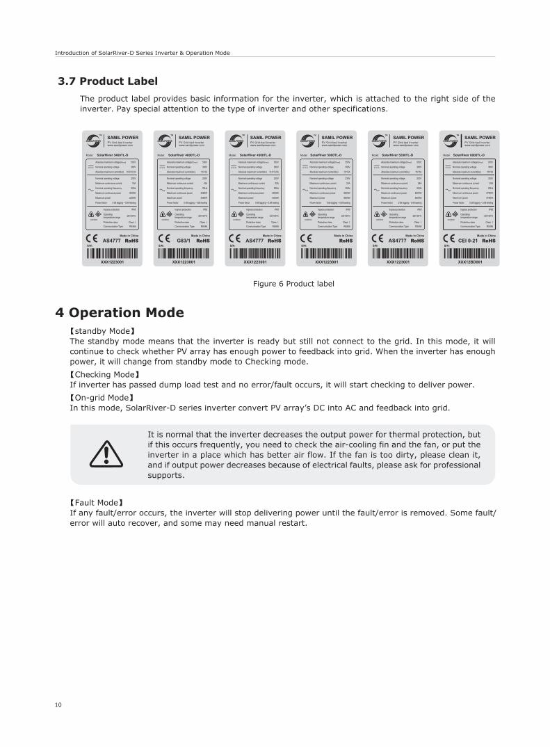
Figure 6 Product label
Model: SolarRiver 3400TL-D
XXX1223001
AS4777 RoHS
550VAbsolute maximum voltage(Vmax)
10.5/10.5AAbsolute maximum current(Isc)
360VNominal operating voltage
230VNominal operating voltage
16AMaximum continuous current
50HzNominal operating frequency
3000W
3200WMaximum power
Maximum continuous power
0.95 lagging ~ 0.95 leadingPower factor
Made in China
TM
www.samilpower.comPV Grid-tied Inverter
IP65Ingress protection
-20/+60°COperating temperature range
Protective class Class Ⅰ
Communication Type RS485
outdoor
S/N:
IP65Ingress protection
-20/+60°COperating temperature range
Protective class Class Ⅰ
Communication Type RS485
outdoor
Model: SolarRiver 4500TL-D
Made in China
TM
www.samilpower.comPV Grid-tied Inverter
550VAbsolute maximum voltage(Vmax)
13.5/13.5AAbsolute maximum current(Isc)
360VNominal operating voltage
230VNominal operating voltage
22AMaximum continuous current
50HzNominal operating frequency
4000W
4300WMaximum power
Maximum continuous power
0.95 lagging ~ 0.95 leadingPower factor
XXX1223001
AS4777 RoHSS/N:
IP65Ingress protection
-20/+60°COperating temperature range
Protective class Class Ⅰ
Communication Type RS485
outdoor
Model: SolarRiver 5000TL-D
Made in China
TM
www.samilpower.comPV Grid-tied Inverter
550VAbsolute maximum voltage(Vmax)
15/15AAbsolute maximum current(Isc)
360VNominal operating voltage
230VNominal operating voltage
23AMaximum continuous current
50HzNominal operating frequency
4600W
4600WMaximum power
Maximum continuous power
0.95 lagging ~ 0.95 leadingPower factor
XXX1223001
RoHSS/N:
IP65Ingress protection
-20/+60°COperating temperature range
Protective class Class Ⅰ
Communication Type RS485
outdoor
Model: SolarRiver 5200TL-D
Made in China
TM
www.samilpower.comPV Grid-tied Inverter
550VAbsolute maximum voltage(Vmax)
15/15AAbsolute maximum current(Isc)
360VNominal operating voltage
230VNominal operating voltage
24AMaximum continuous current
50HzNominal operating frequency
4600W
5000WMaximum power
Maximum continuous power
0.95 lagging ~ 0.95 leadingPower factor
XXX1223001
AS4777 RoHSS/N:
IP65Ingress protection
-20/+60°COperating temperature range
Protective class Class Ⅰ
Communication Type RS485
outdoor
Model: SolarRiver 4000TL-D
Made in China
TM
www.samilpower.comPV Grid-tied Inverter
550VAbsolute maximum voltage(Vmax)
12/12AAbsolute maximum current(Isc)
360VNominal operating voltage
230VNominal operating voltage
16AMaximum continuous current
50HzNominal operating frequency
3680W
3680WMaximum power
Maximum continuous power
0.95 lagging ~ 0.95 leadingPower factor
XXX1223001
G83/1 RoHSS/N:
IP65Ingress protection
-20/+60°COperating temperature range
Protective class Class Ⅰ
Communication Type RS485
outdoor
Model: SolarRiver 6000TL-D
Made in China
TM
www.samilpower.comPV Grid-tied Inverter
550VAbsolute maximum voltage(Vmax)
15/15AAbsolute maximum current(Isc)
360VNominal operating voltage
230VNominal operating voltage
25AMaximum continuous current
50HzNominal operating frequency
5750W
5750WMaximum power
Maximum continuous power
0.95 lagging ~ 0.95 leadingPower factor
XXX12BD001
RoHSS/N:
CEI 0-21
4 Operation Mode【standby Mode】The standby mode means that the inverter is ready but still not connect to the grid. In this mode, it will continue to check whether PV array has enough power to feedback into grid. When the inverter has enough power, it will change from standby mode to Checking mode.
【Checking Mode】If inverter has passed dump load test and no error/fault occurs, it will start checking to deliver power.
【On-grid Mode】In this mode, SolarRiver-D series inverter convert PV array’s DC into AC and feedback into grid.
【Fault Mode】 If any fault/error occurs, the inverter will stop delivering power until the fault/error is removed. Some fault/error will auto recover, and some may need manual restart.
3.7 Product Label
The product label provides basic information for the inverter, which is attached to the right side of the inverter. Pay special attention to the type of inverter and other specifications.
Installation
11
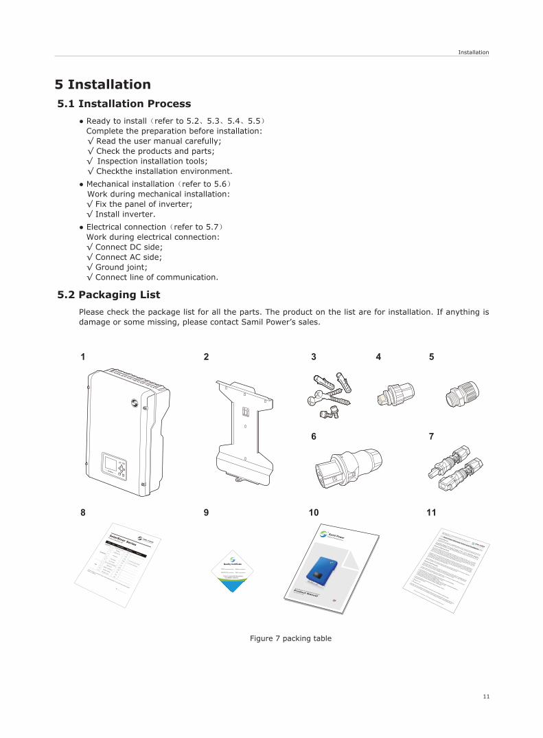
Figure 7 packing table
5 Installation5.1 Installation Process
● Ready to install(refer to 5.2、5.3、5.4、5.5)Complete the preparation before installation: √ Read the user manual carefully; √ Check the products and parts;√ Inspection installation tools; √ Checkthe installation environment.
● Mechanical installation(refer to 5.6) Work during mechanical installation:
√ Fix the panel of inverter;√ Install inverter.
● Electrical connection(refer to 5.7)Work during electrical connection:√ Connect DC side;√ Connect AC side;√ Ground joint;√ Connect line of communication.
5.2 Packaging List
Please check the package list for all the parts. The product on the list are for installation. If anything is damage or some missing, please contact Samil Power’s sales.
6 7
1 2 3 4 5
TM
Samil PowerExpert for PV Grid-tied Inverters
8 9 10 11
SP-SR-D-V1.0-EN
SolarRiver-D Grid-tied Inverter
Product Manual
English
12
Installation
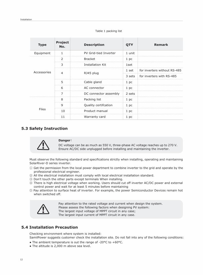
Type Project
No. Description QTY Remark
Equipment 1 PV Grid-tied Inverter 1 unit
Accessories
2 Bracket 1 pc
3 Installation Kit 1set
4
Cable gland
1 set
1 pc
3 sets
Files
5
AC connector 1 pc 6
2 sets7
Product manual
1 pc 8
Quality certifcation
Packing list
DC connector assembly
Warranty card
1 pc
1 pc
1 pc
9
10
11
Table 1 packing list
RJ45 plugfor inverters without RS-485
for inverters with RS-485
Must observe the following standard and specifications strictly when installing, operating and maintaining SolarRiver-D series inverter.
① Get the permission from the local power department to combine inverter to the grid and operate by the professional electrical engineer.
② All the electrical installation must comply with local electrical installation standard.③ Don't touch the other parts except terminals When installing.④ There is high electrical voltage when working. Users should cut off inverter AC/DC power and external
control power and wait for at least 5 minutes before maintaining⑤ Pay attention to surface heat of inverter. For example, the power Semiconductor Devices remain hot
when switched off.
5.3 Safety Instruction
Danger!
DC voltage can be as much as 550 V, three-phase AC voltage reaches up to 270 V. Ensure AC/DC side unplugged before installing and maintaining the inverter.
Pay attention to the rated voltage and current when design the system.Please assess the following factors when designing PV system:The largest input voltage of MPPT circuit in any case;The largest input current of MPPT circuit in any case.
5.4 Installation Precaution
Checking environment where system is installed:SamilPower suggests customer check the installation site. Do not fall into any of the following conditions:
● The ambient temperature is out the range of -20°C to +60°C.● The altitude is 2,000 m above sea level.
Installation
13
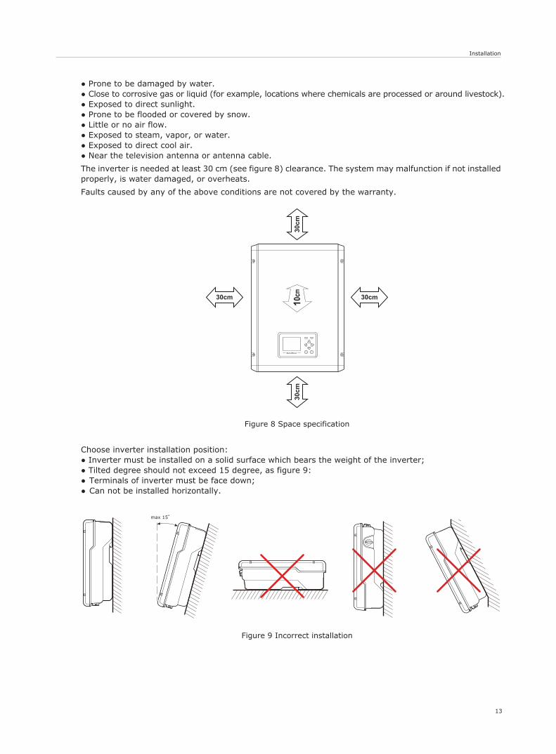
Figure 8 Space specification
Figure 9 Incorrect installation
max 15
30cm
30cm
30cm 30cm
SolarRiver
Normal Fault
OKESC
● Prone to be damaged by water.● Close to corrosive gas or liquid (for example, locations where chemicals are processed or around livestock).● Exposed to direct sunlight. ● Prone to be flooded or covered by snow.● Little or no air flow.● Exposed to steam, vapor, or water.● Exposed to direct cool air.● Near the television antenna or antenna cable.
The inverter is needed at least 30 cm (see figure 8) clearance. The system may malfunction if not installed properly, is water damaged, or overheats.
Faults caused by any of the above conditions are not covered by the warranty.
Choose inverter installation position:● Inverter must be installed on a solid surface which bears the weight of the inverter;● Tilted degree should not exceed 15 degree, as figure 9:● Terminals of inverter must be face down;● Can not be installed horizontally.
Installation
14
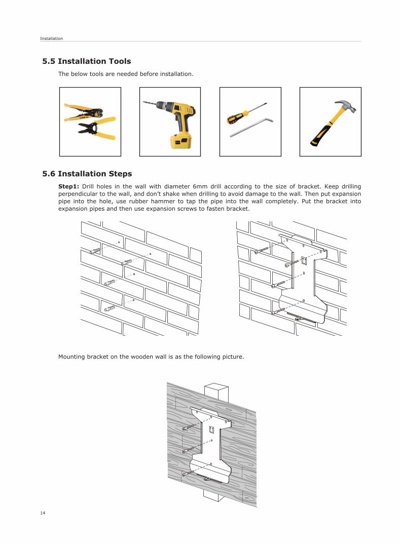
5.5 Installation Tools
The below tools are needed before installation.
5.6 Installation Steps
Step1: Drill holes in the wall with diameter 6mm drill according to the size of bracket. Keep drilling perpendicular to the wall, and don’t shake when drilling to avoid damage to the wall. Then put expansion pipe into the hole, use rubber hammer to tap the pipe into the wall completely. Put the bracket into expansion pipes and then use expansion screws to fasten bracket.
Mounting bracket on the wooden wall is as the following picture.
Installation
15
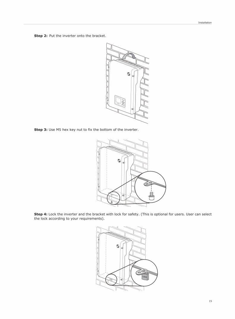
Step 2: Put the inverter onto the bracket.
Step 3: Use M5 hex key nut to fix the bottom of the inverter.
Step 4: Lock the inverter and the bracket with lock for safety. (This is optional for users. User can select the lock according to your requirements).
16
Installation
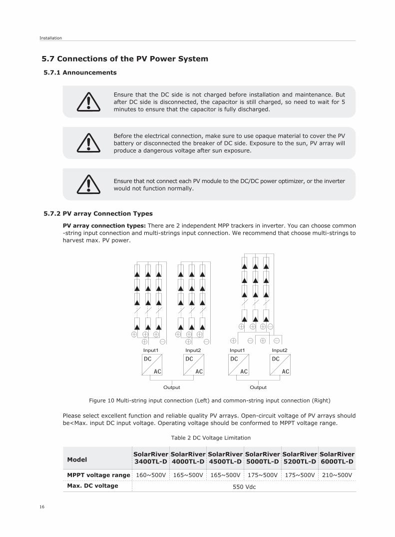
Table 2 DC Voltage Limitation
Figure 10 Multi-string input connection (Left) and common-string input connection (Right)
Ensure that the DC side is not charged before installation and maintenance. But after DC side is disconnected, the capacitor is still charged, so need to wait for 5 minutes to ensure that the capacitor is fully discharged.
Before the electrical connection, make sure to use opaque material to cover the PV battery or disconnected the breaker of DC side. Exposure to the sun, PV array will produce a dangerous voltage after sun exposure.
Ensure that not connect each PV module to the DC/DC power optimizer, or the inverter would not function normally.
5.7 Connections of the PV Power System
5.7.1 Announcements
5.7.2 PV array Connection Types
PV array connection types: There are 2 independent MPP trackers in inverter. You can choose common-string input connection and multi-strings input connection. We recommend that choose multi-strings to harvest max. PV power.
Please select excellent function and reliable quality PV arrays. Open-circuit voltage of PV arrays should be<Max. input DC input voltage. Operating voltage should be conformed to MPPT voltage range.
Model
MPPT voltage range
Max. DC voltage
SolarRiver3400TL-D
160~500V
SolarRiver4000TL-D
165~500V
550 Vdc
SolarRiver4500TL-D
165~500V
SolarRiver5200TL-D
175~500V
SolarRiver5000TL-D
175~500V
SolarRiver6000TL-D
210~500V
Installation
Note!Please don’t connect the PV positive or negative to ground.
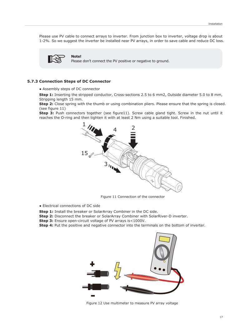
Figure 11 Connection of the connector
Figure 12 Use multimeter to measure PV array voltage
17
4
3
12
15
5.7.3 Connection Steps of DC Connector
● Assembly steps of DC connector
Step 1: Inserting the stripped conductor, Cross-sections 2.5 to 6 mm2, Outside diameter 5.0 to 8 mm, Stripping length 15 mm.Step 2: Close spring with the thumb or using combination pliers. Please ensure that the spring is closed.(see figure 11) Step 3: Push connectors together (see figure11). Screw cable gland tight. Screw in the nut until it reaches the O-ring and then tighten it with at least 2 Nm using a suitable tool. Finished.
● Electrical connections of DC side
Step 1: Install the breaker or SolarArray Combiner in the DC side.Step 2: Disconnect the breaker or SolarArray Combiner with SolarRiver-D inverter.Step 3: Ensure open-circuit voltage of PV arrays is<1000V.Step 4: Put the positive and negative connector into the terminals on the bottom of inverter.
Please use PV cable to connect arrays to inverter. From junction box to inverter, voltage drop is about 1-2%. So we suggest the inverter be installed near PV arrays, in order to save cable and reduce DC loss.
Installation
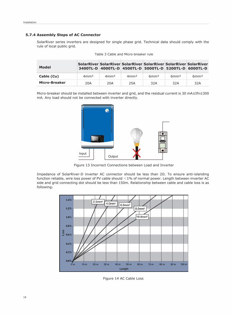
Table 3 Cable and Micro-breaker rule
Figure 13 Incorrect Connections between Load and Inverter
18
InputOutput
SolarRiverESC OK
Figure 14 AC Cable Loss
5.7.4 Assembly Steps of AC Connector
SolarRiver series inverters are designed for single phase grid. Technical data should comply with the rule of local public grid.
Micro-breaker should be installed between inverter and grid, and the residual current is 30 mA≤Ifn≤300 mA. Any load should not be connected with inverter directly.
Impedance of SolarRiver-D inverter AC connector should be less than 2Ω. To ensure anti-islanding function reliable, wire loss power of PV cable should <1% of normal power. Length between inverter AC side and grid connecting dot should be less than 150m. Relationship between cable and cable loss is as following:
Model
Cable (Cu)
Micro-Breaker
SolarRiver3400TL-D
SolarRiver4000TL-D
4mm²
20A
4mm²
20A
SolarRiver4500TL-D
25A
4mm²
SolarRiver5200TL-D
32A
6mm²
SolarRiver5000TL-D
32A
6mm²
SolarRiver6000TL-D
32A
6mm²
Installation
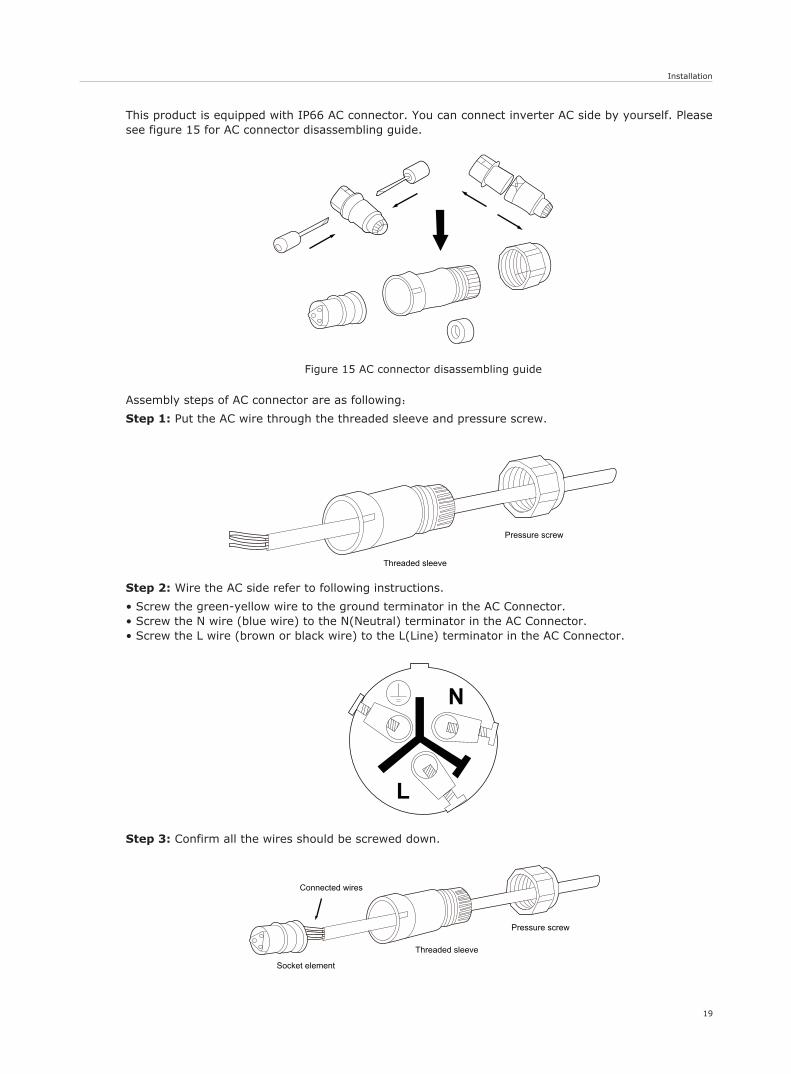
Figure 15 AC connector disassembling guide
19
Threaded sleeve
Pressure screw
N
L
Socket element
Threaded sleeve
Connected wires
Pressure screw
This product is equipped with IP66 AC connector. You can connect inverter AC side by yourself. Please see figure 15 for AC connector disassembling guide.
Assembly steps of AC connector are as following:
Step 1: Put the AC wire through the threaded sleeve and pressure screw.
Step 2: Wire the AC side refer to following instructions.
• Screw the green-yellow wire to the ground terminator in the AC Connector.• Screw the N wire (blue wire) to the N(Neutral) terminator in the AC Connector.• Screw the L wire (brown or black wire) to the L(Line) terminator in the AC Connector.
Step 3: Confirm all the wires should be screwed down.
Installation
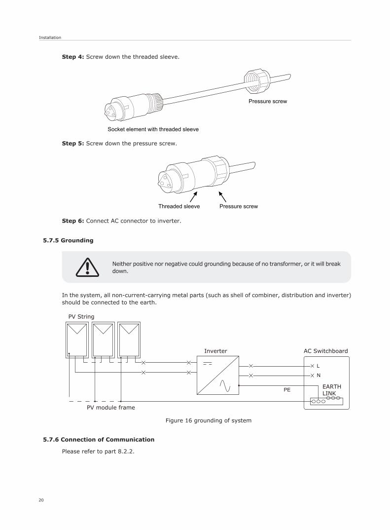
Figure 16 grounding of system
20
Socket element with threaded sleeve
Pressure screw
Threaded sleeve Pressure screw
PV String
Inverter
PE
L
N
PV module frame
AC Switchboard
EARTHLINK
Neither positive nor negative could grounding because of no transformer, or it will break down.
Step 4: Screw down the threaded sleeve.
Step 5: Screw down the pressure screw.
Step 6: Connect AC connector to inverter.
In the system, all non-current-carrying metal parts (such as shell of combiner, distribution and inverter) should be connected to the earth.
5.7.5 Grounding
5.7.6 Connection of Communication
Please refer to part 8.2.2.
Run the Inverter
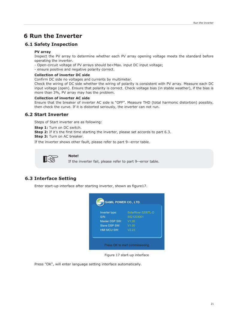
Figure 17 start-up interface
21
Press OK to start commissioning
SAMIL POWER CO., LTD.
SolarRiver 5200TL-DS521233001V1.00V1.00V2.23
Inverter type:S/N:Master DSP SW:Slave DSP SW:HMI MCU SW:
6 Run the Inverter6.1 Safety Inspection
PV arrayInspect the PV array to determine whether each PV array opening voltage meets the standard before operating the inverter.- Open-circuit voltage of PV arrays should be<Max. input DC input voltage;- ensure positive and negative polarity correct.
Collection of inverter DC sideConfirm DC side no voltages and currents by multimeter.Check the wiring of DC side whether the wiring of polarity is consistent with PV array. Measure each DC input voltage (open). Ensure that polarity is correct. Check voltage bias (in stable weather), if the bias is more than 3%, PV array may has the problem.
Collection of inverter AC sideEnsure that the breaker of inverter AC side is “OFF”. Measure THD (total harmonic distortion) possibly, then check the curve. If it is distorted seriously, the inverter can not run.
6.2 Start Inverter
Steps of Start inverter are as following:
Step 1: Turn on DC switch.Step 2: If it’s the first time starting the inverter, please set accords to part 6.3.Step 3: Turn on AC breaker.
If the inverter shows other fault, please refer to part 9--error table.
6.3 Interface Setting
Enter start-up interface after starting inverter, shown as figure17.
Press "OK", will enter language setting interface automatically.
Note!
If the inverter fail, please refer to part 9--error table.
Run the Inverter
22
Date/Time
Press OK to confirm
0 1 22 3 0 3
1 0 1: 0
0
DDMM
hh mm
YYYY- -
Up/Down : Increase/Decrease valueLeft/Right : Move Selection
English
French
Espana
German
Italy
Language
Press OK to confirm
Country
Press OK to confirm
Germany
Italy
Australia
Spanish
Czech
GreeceIslands
GreeceContin
Netherland
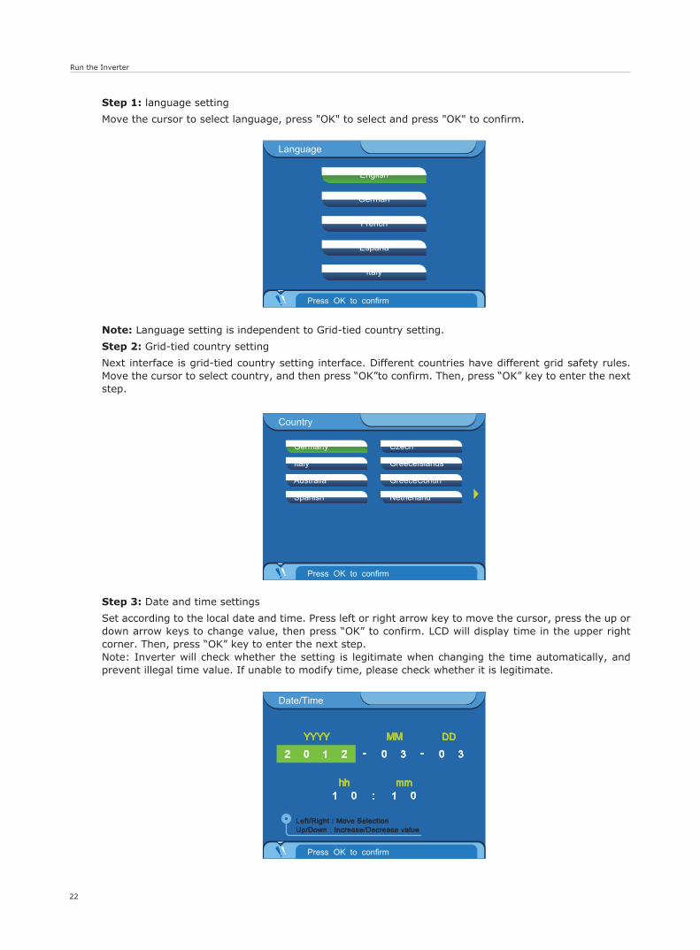
Step 1: language setting
Move the cursor to select language, press "OK" to select and press "OK" to confirm.
Note: Language setting is independent to Grid-tied country setting.
Step 2: Grid-tied country setting
Next interface is grid-tied country setting interface. Different countries have different grid safety rules. Move the cursor to select country, and then press “OK”to confirm. Then, press “OK” key to enter the next step.
Step 3: Date and time settings
Set according to the local date and time. Press left or right arrow key to move the cursor, press the up or down arrow keys to change value, then press “OK” to confirm. LCD will display time in the upper right corner. Then, press “OK” key to enter the next step.Note: Inverter will check whether the setting is legitimate when changing the time automatically, and prevent illegal time value. If unable to modify time, please check whether it is legitimate.
Run the Inverter & Operation
23
Table 4 LED statutes
End commission
Press OK to confirm
Current Country:Germany
Press OK to Start runningPress ESC to Back
LED
green
red
Flash
Wait state
Fault state
Light
Normal state
Permanent state
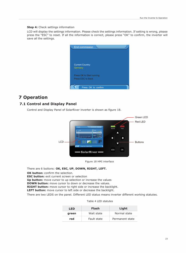
Figure 18 HMI interface
SolarRiverESC OK
Home 2012-03-03 10 00 00: :
Press Esc to Main Menu
Power
Today
Total
0.0 W
0.0 KWh0.0 KWh
=~
208.4 V205.9 V
1.045 kw
49.99 Hz
t
kwh
Green LED
Red LED
ButtonsLCD
7 Operation7.1 Control and Display Panel
Control and Display Panel of SolarRiver inverter is shown as figure 18.
There are 6 buttons: OK, ESC, UP, DOWN, RIGHT, LEFT.
OK button: confirm the selection.ESC button: exit current screen or selectionUp button: move cursor to up selection or increase the valuesDOWN button: move cursor to down or decrease the values.RIGHT button: move cursor to right side or increase the backlight.LEFT button: move cursor to left side or decrease the backlight.
There are two LEDS on the panel. Different LED status means inverter different working statutes.
Step 4: Check settings information
LCD will display the settings information. Please check the settings information. If setting is wrong, please press the “ESC” to reset. If all the information is correct, please press “OK” to confirm, the inverter will save all the settings.
Operation
24
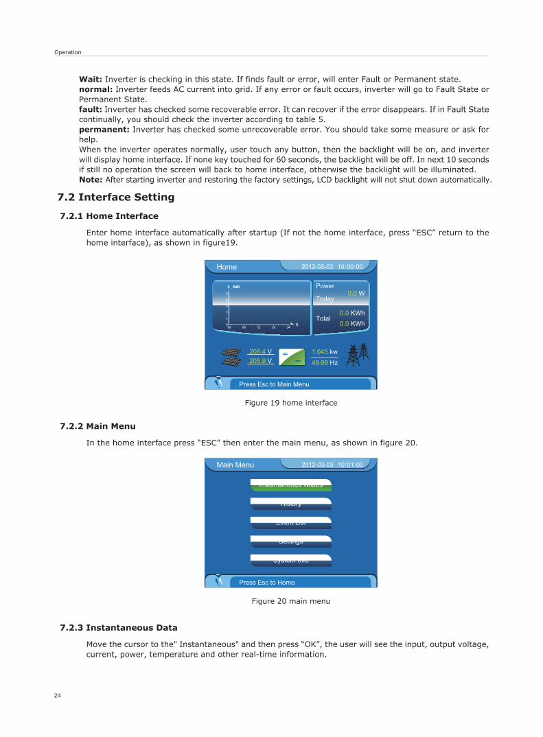
Figure 19 home interface
Home 2012-03-03 10 00 00: :
Press Esc to Main Menu
Power
Today
Total
0.0 W
0.0 KWh0.0 KWh
=~
208.4 V205.9 V
1.045 kw
49.99 Hz
t
kwh
Figure 20 main menu
Instantaneous values
Event List
Settings
History
System Info
Main Menu 2012-03-03 10 01 00: :
Press Esc to Home
Wait: Inverter is checking in this state. If finds fault or error, will enter Fault or Permanent state.normal: Inverter feeds AC current into grid. If any error or fault occurs, inverter will go to Fault State or Permanent State.fault: Inverter has checked some recoverable error. It can recover if the error disappears. If in Fault State continually, you should check the inverter according to table 5.permanent: Inverter has checked some unrecoverable error. You should take some measure or ask for help.When the inverter operates normally, user touch any button, then the backlight will be on, and inverter will display home interface. If none key touched for 60 seconds, the backlight will be off. In next 10 seconds if still no operation the screen will back to home interface, otherwise the backlight will be illuminated. Note: After starting inverter and restoring the factory settings, LCD backlight will not shut down automatically.
7.2 Interface Setting
7.2.1 Home Interface
Enter home interface automatically after startup (If not the home interface, press “ESC” return to the home interface), as shown in figure19.
7.2.2 Main Menu
In the home interface press “ESC” then enter the main menu, as shown in figure 20.
7.2.3 Instantaneous Data
Move the cursor to the" Instantaneous" and then press “OK”, the user will see the input, output voltage, current, power, temperature and other real-time information.
Operation
25
Figure 21 settings interface
Settings 2012-03-03 10 02 25: :
Press Esc to Main Menu
Language
Date/Time
Clear date
Clear events
LCD contrast
Country
Input config
Reset Password
Network
AutoTest(Italy)
Factory set
Safety param
7.2.4 Historical Data
Move the cursor to the" History" and then press “OK”, the user will see the power amount histogram of every hour. The user press the left or right arrow key to see daily electricenergy production histogram in the current month, mensal electricenergy production histogram in the current in the current year.
7.2.5 Event List
Move the cursor to the" Event List" and then press “OK”, the user will see the list of events of inverter. Record 100 event information at most. Press the right or left keys to select events.
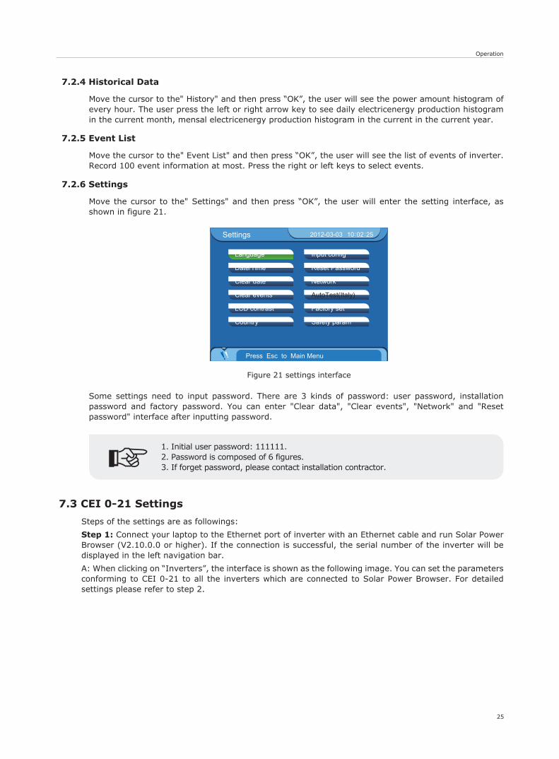
7.2.6 Settings
Move the cursor to the" Settings" and then press “OK”, the user will enter the setting interface, as shown in figure 21.
Some settings need to input password. There are 3 kinds of password: user password, installation password and factory password. You can enter "Clear data", "Clear events", "Network" and "Reset password" interface after inputting password.
7.3 CEI 0-21 Settings
Steps of the settings are as followings:
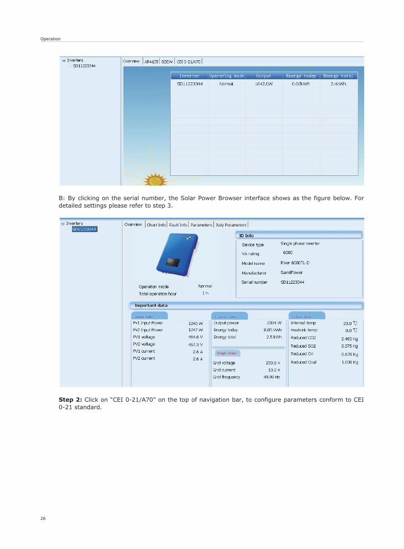
Step 1: Connect your laptop to the Ethernet port of inverter with an Ethernet cable and run Solar Power Browser (V2.10.0.0 or higher). If the connection is successful, the serial number of the inverter will be displayed in the left navigation bar.
A: When clicking on “Inverters”, the interface is shown as the following image. You can set the parameters conforming to CEI 0-21 to all the inverters which are connected to Solar Power Browser. For detailed settings please refer to step 2.
1. Initial user password: 111111.2. Password is composed of 6 figures. 3. If forget password, please contact installation contractor.
Operation
26
B: By clicking on the serial number, the Solar Power Browser interface shows as the figure below. For detailed settings please refer to step 3.
Step 2: Click on “CEI 0-21/A70” on the top of navigation bar, to configure parameters conform to CEI 0-21 standard.
Operation
27
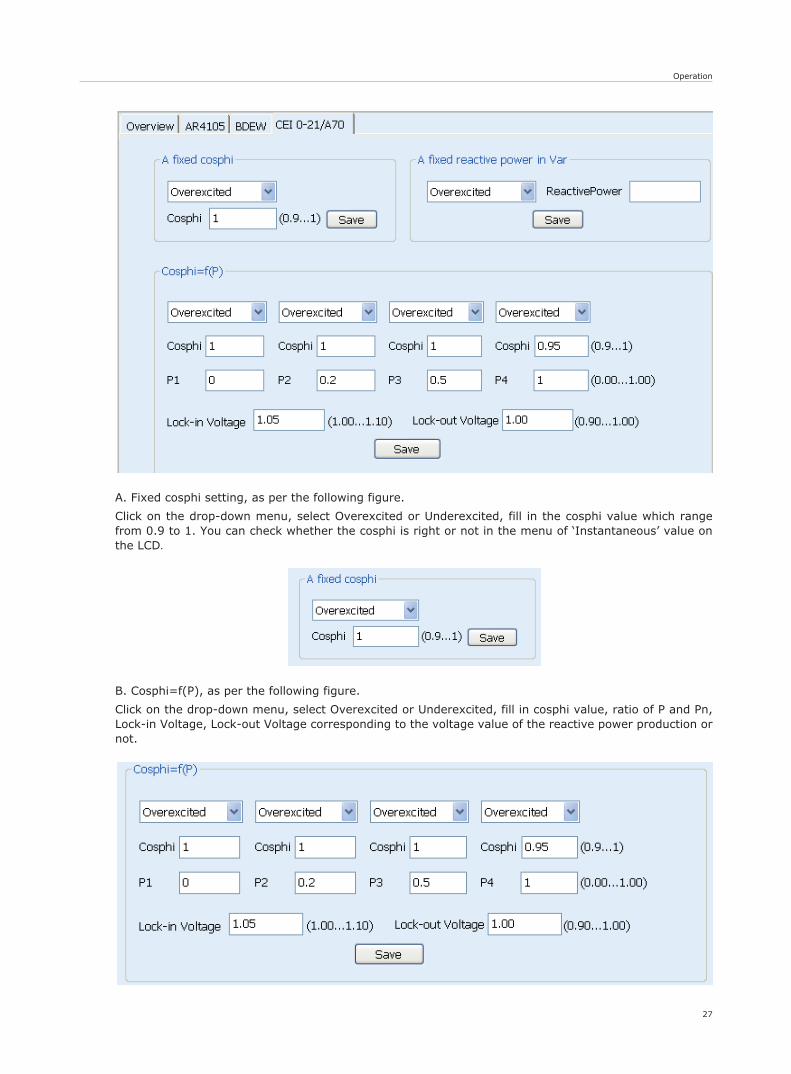
A. Fixed cosphi setting, as per the following figure.
Click on the drop-down menu, select Overexcited or Underexcited, fill in the cosphi value which range from 0.9 to 1. You can check whether the cosphi is right or not in the menu of ‘Instantaneous’ value on the LCD.
B. Cosphi=f(P), as per the following figure.
Click on the drop-down menu, select Overexcited or Underexcited, fill in cosphi value, ratio of P and Pn, Lock-in Voltage, Lock-out Voltage corresponding to the voltage value of the reactive power production or not.
Operation
28
Control mode
Local
Remote
Communication
On
Off
Pin1
-
high
low
high
low
Pin2
-
high
high
low
low
47.5-51.5 Hz
Frequency range
47.5-51.5 Hz
49.5-50.5 Hz
49.5-50.5 Hz
47.5-51.5 Hz
normal
Status
Waiting(reconnecting)
high
Waiting(reconnecting)
normal
Cos-phi
P1 P2 P3
P/Pn0.2 0.5 1
0.95
1
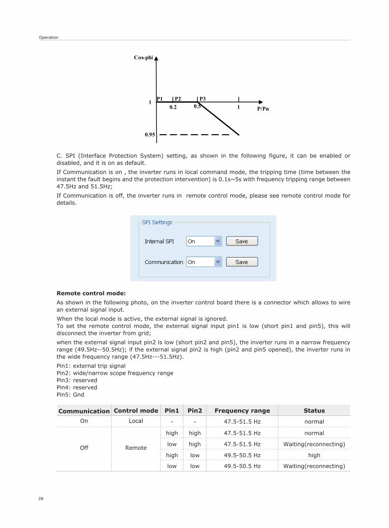
C. SPI (Interface Protection System) setting, as shown in the following figure, it can be enabled or disabled, and it is on as default.
If Communication is on , the inverter runs in local command mode, the tripping time (time between the instant the fault begins and the protection intervention) is 0.1s~5s with frequency tripping range between 47.5Hz and 51.5Hz;
If Communication is off, the inverter runs in remote control mode, please see remote control mode for details.
Remote control mode:
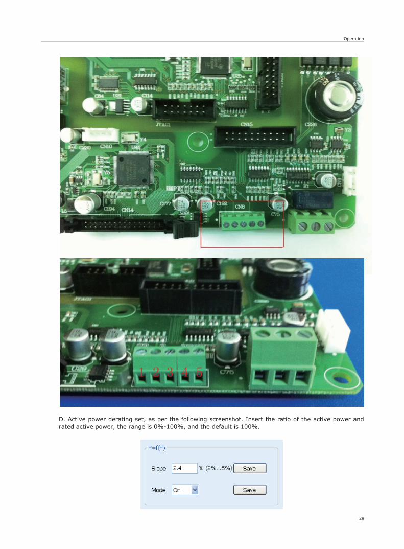
As shown in the following photo, on the inverter control board there is a connector which allows to wire an external signal input.
When the local mode is active, the external signal is ignored.To set the remote control mode, the external signal input pin1 is low (short pin1 and pin5), this will disconnect the inverter from grid;
when the external signal input pin2 is low (short pin2 and pin5), the inverter runs in a narrow frequency range (49.5Hz--50.5Hz); if the external signal pin2 is high (pin2 and pin5 opened), the inverter runs in the wide frequency range (47.5Hz---51.5Hz).
Pin1: external trip signalPin2: wide/narrow scope frequency rangePin3: reservedPin4: reservedPin5: Gnd
Operation
29
D. Active power derating set, as per the following screenshot. Insert the ratio of the active power and rated active power, the range is 0%-100%, and the default is 100%.

30
Operation
Po
t
100%
50%
0%
100%Pn50%Pn
Act
ive
pow
er In
E. Active power derating settings, as the following picture. Fill in the ratio of the active power and rated active power, the range is 0%-100%, and the default is 100%.
Step 3: Inverter safety parameters setting, as the following picture. Before setting, click ‘Read’ Data to refresh current data then set parameters, click ‘save’ at last. The following picture shows default parameters of CEI 0-21.
Communication and Monitoring
31
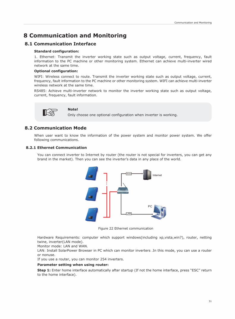
Figure 22 Ethernet communication
WAN
Router
8 Communication and Monitoring8.1 Communication Interface
Standard configuration:
1. Ethernet: Transmit the inverter working state such as output voltage, current, frequency, fault information to the PC machine or other monitoring system. Ethernet can achieve multi-inverter wired network at the same time.
Optional configuration:
WIFI: Wireless connect to route. Transmit the inverter working state such as output voltage, current, frequency, fault information to the PC machine or other monitoring system. WIFI can achieve multi-inverter wireless network at the same time.
RS485: Achieve multi-inverter network to monitor the inverter working state such as output voltage, current, frequency, fault information.
8.2 Communication Mode
When user want to know the information of the power system and monitor power system. We offer following communications.
8.2.1 Ethernet Communication
You can connect inverter to Internet by router (the router is not special for inverters, you can get any brand in the market). Then you can see the inverter’s data in any place of the world.
Hardware Requirements: computer which support windows(including xp,vista,win7), router, netting twine, inverter(LAN mode).Monitor mode: LAN and WAN.LAN: Install SolarPower Browser in PC which can monitor inverters .In this mode, you can use a router or nonuse.If you use a router, you can monitor 254 inverters.
Parameter setting when using router:
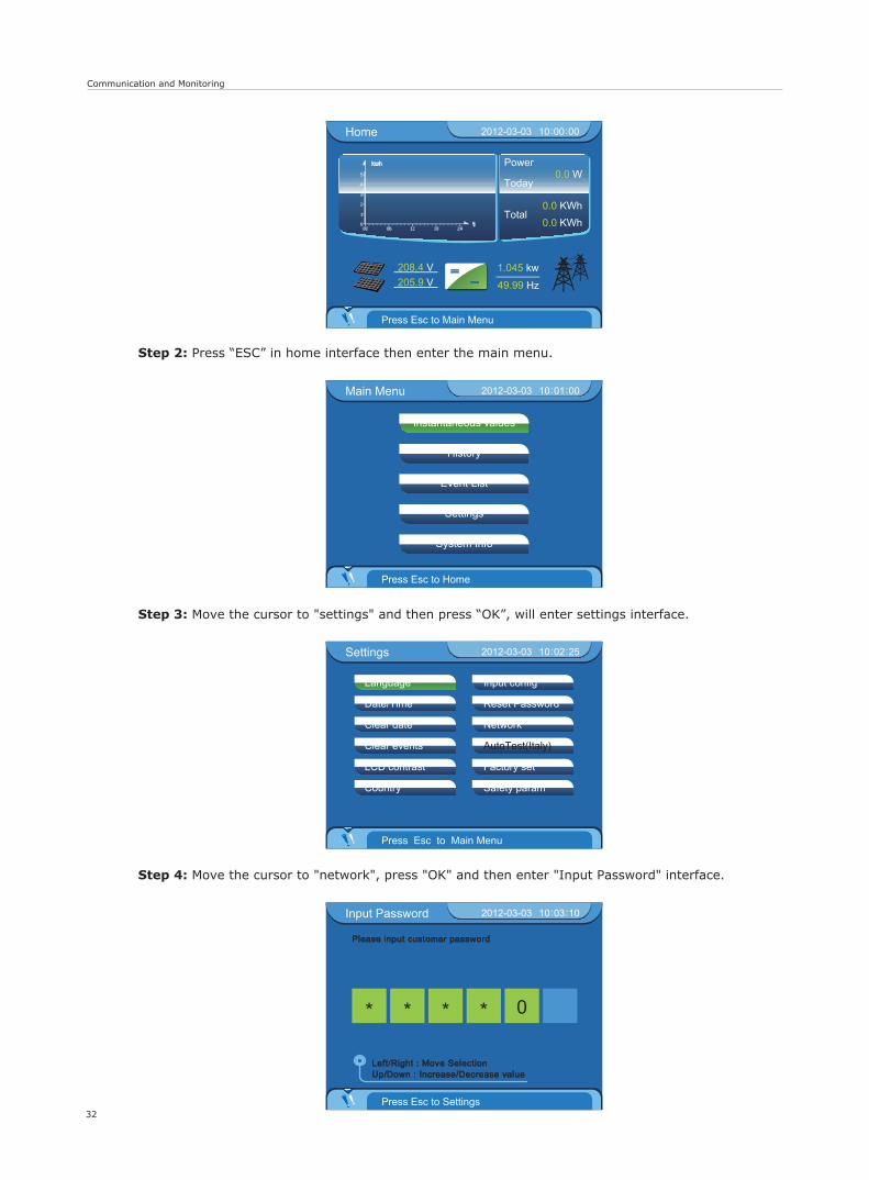
Step 1: Enter home interface automatically after startup (If not the home interface, press “ESC” return to the home interface).
Note!
Only choose one optional configuration when inverter is working.
Communication and Monitoring
32
Home 2012-03-03 10 00 00: :
Press Esc to Main Menu
Power
Today
Total
0.0 W
0.0 KWh0.0 KWh
=~
208.4 V205.9 V
1.045 kw
49.99 Hz
t
kwh
Instantaneous values
Event List
Settings
History
System Info
Main Menu 2012-03-03 10 01 00: :
Press Esc to Home
Settings 2012-03-03 10 02 25: :
Press Esc to Main Menu
Language
Date/Time
Clear date
Clear events
LCD contrast
Country
Input config
Reset Password
Network
AutoTest(Italy)
Factory set
Safety param
Input Password 2012-03-03 10 03 10: :
Press Esc to Settings
Please input customer password
0
Up/Down : Increase/Decrease valueLeft/Right : Move Selection
Step 2: Press “ESC” in home interface then enter the main menu.
Step 3: Move the cursor to "settings" and then press “OK”, will enter settings interface.
Step 4: Move the cursor to "network", press "OK" and then enter "Input Password" interface.
Communication and Monitoring
33
Ethernet 2012-03-03 10 16 40: :
Confirm?
Auto-IP/DHCP
Manual-IP
Current mode: Auto-IP/DHCP
Ethernet 2012-03-03 10 16 23: :
Press OK to confirm
Auto-IP/DHCP
Manual-IP
Current mode: Auto-IP/DHCP
Ethernet 2012-03-03 10 22 23: :
Press OK to confirm
Auto-IP/DHCP
Manud-IP
Current mode: Manual-IP
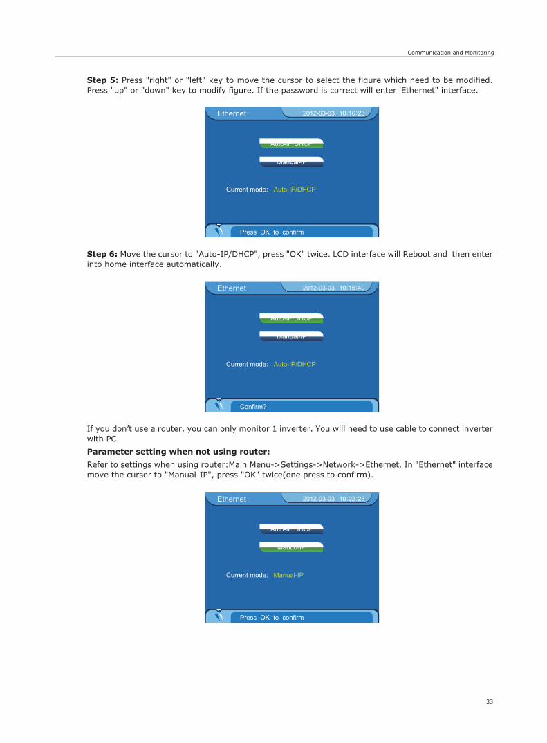
Step 5: Press "right" or "left" key to move the cursor to select the figure which need to be modified. Press "up" or "down" key to modify figure. If the password is correct will enter 'Ethernet" interface.
Step 6: Move the cursor to "Auto-IP/DHCP", press "OK" twice. LCD interface will Reboot and then enter into home interface automatically.
If you don’t use a router, you can only monitor 1 inverter. You will need to use cable to connect inverter with PC.
Parameter setting when not using router:
Refer to settings when using router:Main Menu->Settings->Network->Ethernet. In "Ethernet" interface move the cursor to "Manual-IP", press "OK" twice(one press to confirm).
34
Communication and Monitoring
Ethernet 2012-03-03 10 22 50: :
Confirm?
Auto-IP/DHCP
Manud-IP
Current mode: Manual-IP
Manual-IP 2012-03-03 10 26 05: :
Press OK to confirm
Up/Down : Increase/Decrease valueLeft/Right : Move Selection
IP:
2 5 5 . 2 5 5 . 2 5 5 . 0 0 0
0 0 0 . 0 0 0 . 0 0 0 . 0 0 0
0 0 0 . 0 0 0 . 0 0 0 . 0 0 0
SubnetMask:
Gateway:
DNS:
1 9 2 . 1 6 8 . 0 0 0 . 0 0 2
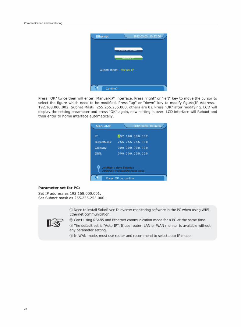
Press "OK" twice then will enter "Manual-IP" interface. Press "right" or "left" key to move the cursor to select the figure which need to be modified. Press "up" or "down" key to modify figure(IP Address:192.168.000.002. Subnet Mask:255.255.255.000, others are 0). Press “OK” after modifying. LCD will display the setting parameter and press “OK” again, now setting is over. LCD interface will Reboot and then enter to home interface automatically.
Parameter set for PC:
Set IP address as 192.168.000.001,Set Subnet mask as 255.255.255.000.
① Need to install SolarRiver-D inverter monitoring software in the PC when using WIFI, Ethernet communication.
② Can’t using RS485 and Ethernet communication mode for a PC at the same time.
③ The default set is “Auto IP”. If use router, LAN or WAN monitor is available without any parameter setting.
④ In WAN mode, must use router and recommend to select auto IP mode.
Communication and Monitoring
35
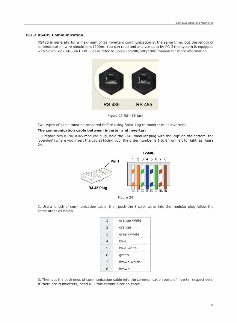
orange white
orange
green white
blue
blue white
green
brown white
brown
1
2
3
4
5
6
7
8
Figure 24
G/ GB/ Br/ BrO/ O B
1 2 3 4
T-568B5 6 7 8
RJ-45 Plug
Pin 1
Figure 23 RS-485 jack
8.2.2 RS485 Communication
RS485 is generally for a maximum of 32 inverters communication at the same time. But the length of communication wire should be≤1200m. You can read and analyse data by PC if the system is equipped with Solar-Log200/500/1000. Please refer to Solar-Log200/500/1000 manual for more information.
Two types of cable must be prepared before using Solar-Log to monitor mult-inverters.
The communication cable between inverter and inverter:
1. Prepare two 8-PIN RJ45 modular plug, hold the RJ45 modular plug with the 'clip' on the bottom, the 'opening' (where you insert the cable) facing you, the order number is 1 to 8 from left to right, as figure 24.
2. Use a length of communication cable, then push the 8 color wires into the modular plug follow the same order as below.
3. Then put the both ends of communication cable into the communication ports of inverter respectively. If there are N inverters, need N-1 this communication cable.
Communication and Monitoring
36
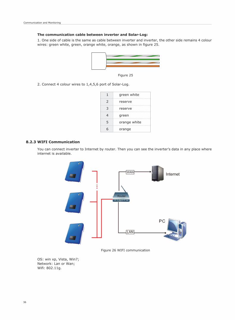
green white
reserve
reserve
green
orange white
orange
1
2
3
4
5
6
Figure 26 WIFI communication
WAN
Router
Figure 25
8.2.3 WIFI Communication
You can connect inverter to Internet by router. Then you can see the inverter’s data in any place where internet is available.
OS: win xp, Vista, Win7;Network: Lan or Wan;Wifi: 802.11g.
The communication cable between inverter and Solar-Log:
1. One side of cable is the same as cable between inverter and inverter, the other side remains 4 colour wires: green white, green, orange white, orange, as shown in figure 25.
2. Connect 4 colour wires to 1,4,5,6 port of Solar-Log.
Communication and Monitoring
37
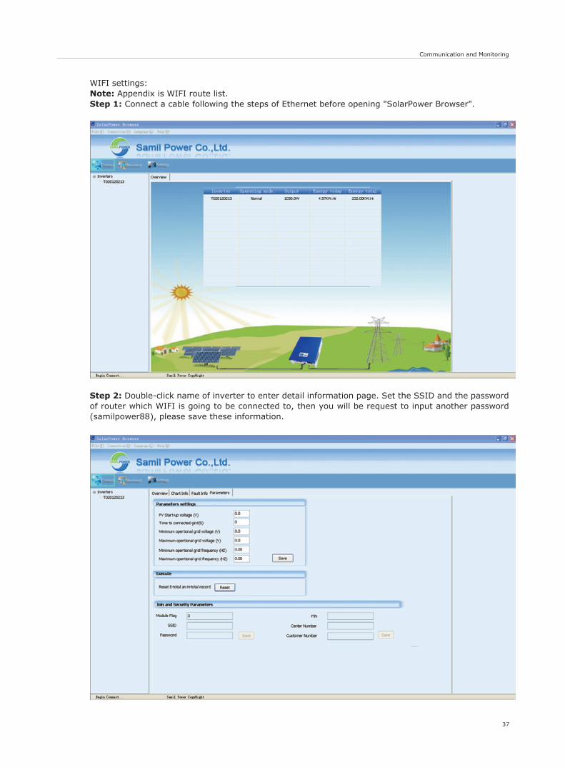
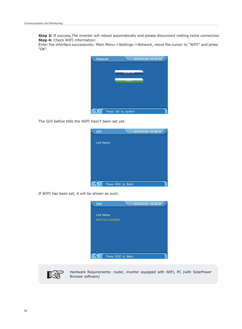
WIFI settings:Note: Appendix is WIFI route list.Step 1: Connect a cable following the steps of Ethernet before opening "SolarPower Browser".
Step 2: Double-click name of inverter to enter detail information page. Set the SSID and the password of router which WIFI is going to be connected to, then you will be request to input another password (samilpower88), please save these information.
38
Communication and Monitoring
Network 2012-03-03 10 27 23: :
Press OK to confirm
Ethernet
WIFI
Wifi 2012-03-03 10 28 10: :
Press ESC to Back
Link Name:
Wifi 2012-03-03 10 28 50: :
Press ESC to Back
Link Name:
BAFFAL0-5D8959
Step 3: If success,The inverter will reboot automatically and please disconnect netting twine connection.Step 4: Check WIFI information:Enter the interface successively: Main Menu->Settings->Network, move the cursor to "WIFI" and press "OK".
The GUI bellow tells the WIFI hasn’t been set yet.
If WIFI has been set, it will be shown as such.
Hardware Requirements: router, inverter equipped with WIFI, PC (with SolarPower Browser software)
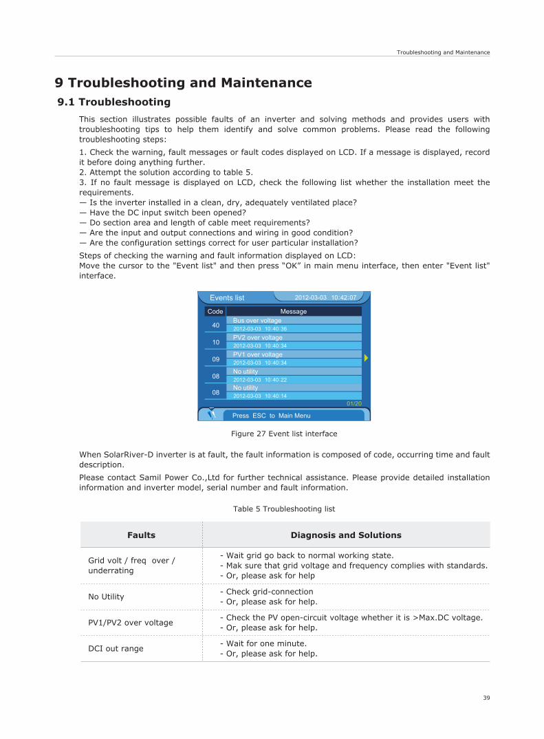
Figure 27 Event list interface
Events list 2012-03-03 10 42 07: :
Press ESC to Main Menu
Code Message
40Bus over voltage2012-03-03 10 40 36: :
10PV2 over voltage2012-03-03 10 40 34: :
09PV1 over voltage2012-03-03 10 40 34: :
08No utility2012-03-03 10 40 22: :
08No utility2012-03-03 10 40 14: :
01/20
- Wait grid go back to normal working state.- Mak sure that grid voltage and frequency complies with standards.- Or, please ask for help
- Check grid-connection- Or, please ask for help.
- Check the PV open-circuit voltage whether it is >Max.DC voltage.- Or, please ask for help.
- Wait for one minute.- Or, please ask for help.
Table 5 Troubleshooting list
Troubleshooting and Maintenance
39
9 Troubleshooting and Maintenance9.1 Troubleshooting
This section illustrates possible faults of an inverter and solving methods and provides users with troubleshooting tips to help them identify and solve common problems. Please read the following troubleshooting steps:
1. Check the warning, fault messages or fault codes displayed on LCD. If a message is displayed, record it before doing anything further.2. Attempt the solution according to table 5.3. If no fault message is displayed on LCD, check the following list whether the installation meet the requirements.— Is the inverter installed in a clean, dry, adequately ventilated place?— Have the DC input switch been opened? — Do section area and length of cable meet requirements?— Are the input and output connections and wiring in good condition?— Are the configuration settings correct for user particular installation?
Steps of checking the warning and fault information displayed on LCD:Move the cursor to the "Event list" and then press “OK” in main menu interface, then enter "Event list" interface.
When SolarRiver-D inverter is at fault, the fault information is composed of code, occurring time and fault description.
Please contact Samil Power Co.,Ltd for further technical assistance. Please provide detailed installation information and inverter model, serial number and fault information.
Grid volt / freq over /underrating
No Utility
PV1/PV2 over voltage
DCI out range
Faults Diagnosis and Solutions
Troubleshooting and Maintenance
40
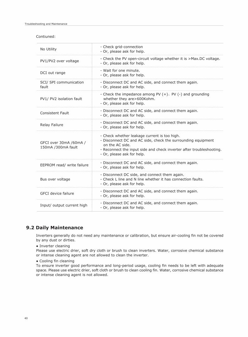
SCI/ SPI communicationfault
- Disconnect DC and AC side, and connect them again.- Or, please ask for help.
PV1/ PV2 isolation fault- Check the impedance among PV (+)、PV (-) and grounding
whether they are>600Kohm.- Or, please ask for help.
Consistent Fault- Disconnect DC and AC side, and connect them again.- Or, please ask for help.
Relay Failure- Disconnect DC and AC side, and connect them again.- Or, please ask for help.
GFCI over 30mA /60mA /150mA /300mA fault
- Check whether leakage current is too high.- Disconnect DC and AC side, check the surrounding equipment
on the AC side.- Reconnect the input side and check inverter after troubleshooting.- Or, please ask for help.
EEPROM read/ write failure- Disconnect DC and AC side, and connect them again.- Or, please ask for help.
Bus over voltage- Disconnect DC side, and connect them again.- Check L line and N line whether it has connection faults.- Or, please ask for help.
GFCI device failure- Disconnect DC and AC side, and connect them again.- Or, please ask for help.
- Disconnect DC and AC side, and connect them again.- Or, please ask for help.
Input/ output current high
9.2 Daily Maintenance
Inverters generally do not need any maintenance or calibration, but ensure air-cooling fin not be covered by any dust or dirties.
● Inverter cleaningPlease use electric drier, soft dry cloth or brush to clean inverters. Water, corrosive chemical substance or intense cleaning agent are not allowed to clean the inverter.
● Cooling fin cleaningTo ensure inverter good performance and long-period usage, cooling fin needs to be left with adequate space. Please use electric drier, soft cloth or brush to clean cooling fin. Water, corrosive chemical substance or intense cleaning agent is not allowed.
Contiuned:
- Check grid-connection- Or, please ask for help.
- Check the PV open-circuit voltage whether it is >Max.DC voltage.- Or, please ask for help.
- Wait for one minute.- Or, please ask for help.
No Utility
PV1/PV2 over voltage
DCI out range
Decommissioning & Technical Data
41
10 Decommissioning10.1 Decommissioning Steps
1. Switch off the AC grid;2. Switch Off the DC switch;3. Wait 5 minutes;4. Release the DC connectors;5. Release the AC connectors.
Now inverters can be demounted safely.
10.2 Package
Please pack the inverter with the original package as far as possible. If original package is not available, use an equivalent carton that meets the following requirements: 1. Load more than 50 kg; 2. With handle; 3. Can be fully sealed off.
10.3 Storage
Store the inverter in dry place where temperatures are between -25 °C - +70 °C.
10.4 Disposal
Please deliver inverters and packing materials to a suitable space where should meet disposal regulations for electronic scrap at the end of its service.
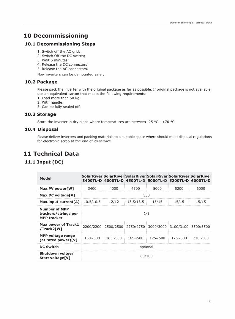
11 Technical Data11.1 Input (DC)
optional
60/100
ModelSolarRiver3400TL-D
SolarRiver4000TL-D
SolarRiver4500TL-D
SolarRiver5000TL-D
SolarRiver5200TL-D
Max.PV power[W]
Max.DC voltage[V]
Max.input current[A]
Number of MPPtrackers/strings perMPP tracker
Max power of Track1/Track2[W]
MPP voltage range(at rated power)[V]
DC Switch
Shutdown voltge/Start voltage[V]
3400
10.5/10.5
2200/2200
160~500 165~500 165~500 175~500 175~500 210~500
2500/2500 2750/2750 3000/3000 3100/3100 3500/3500
2/1
12/12 13.5/13.5 15/15 15/1515/15
4000 4500 5000 5200
SolarRiver6000TL-D
6000
550
42
Technical Data
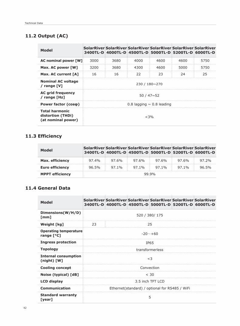
11.2 Output (AC)
<3%
ModelSolarRiver3400TL-D
SolarRiver4000TL-D
SolarRiver4500TL-D
SolarRiver5000TL-D
SolarRiver5200TL-D
AC nominal power [W]
Max. AC power [W]
Max. AC current [A]
Nominal AC voltage/ range [V]
AC grid frequency/ range [Hz]
Power factor (cosφ)
Total harmonicdistortion (THDi)(at nominal power)
3000
16
0.8 lagging ~ 0.8 leading
50 / 47~52
230 / 180~270
16 22 23 2524
3680 4000 4600 4600
SolarRiver6000TL-D
5750
3200 3680 4300 4600 5000 5750
11.3 Efficiency
ModelSolarRiver3400TL-D
SolarRiver4000TL-D
SolarRiver4500TL-D
SolarRiver5000TL-D
SolarRiver5200TL-D
Max. efficiency
Euro efficiency
MPPT efficiency
97.4%
99.9%
97.6% 97.6% 97.6% 97.6%
SolarRiver6000TL-D
97.2%
96.5% 97.1% 97.1% 97.1% 97.1% 96.5%
11.4 General Data
ModelSolarRiver3400TL-D
SolarRiver4000TL-D
SolarRiver4500TL-D
SolarRiver5000TL-D
SolarRiver5200TL-D
Dimensions(W/H/D)[mm]
Weight [kg]
Ingress protection
Topology
Cooling concept
Noise (typical) [dB]
LCD display
Communication
Standard warranty[year]
Internal consumption(night) [W]
Operating temperaturerange [°C] -20~+60
IP65
transformerless
<3
Convection
< 30
3.5 inch TFT LCD
Ethernet(standard) / optional for RS485 / WiFi
5
520 / 380/ 175
SolarRiver6000TL-D
23 25
Guarantees
43
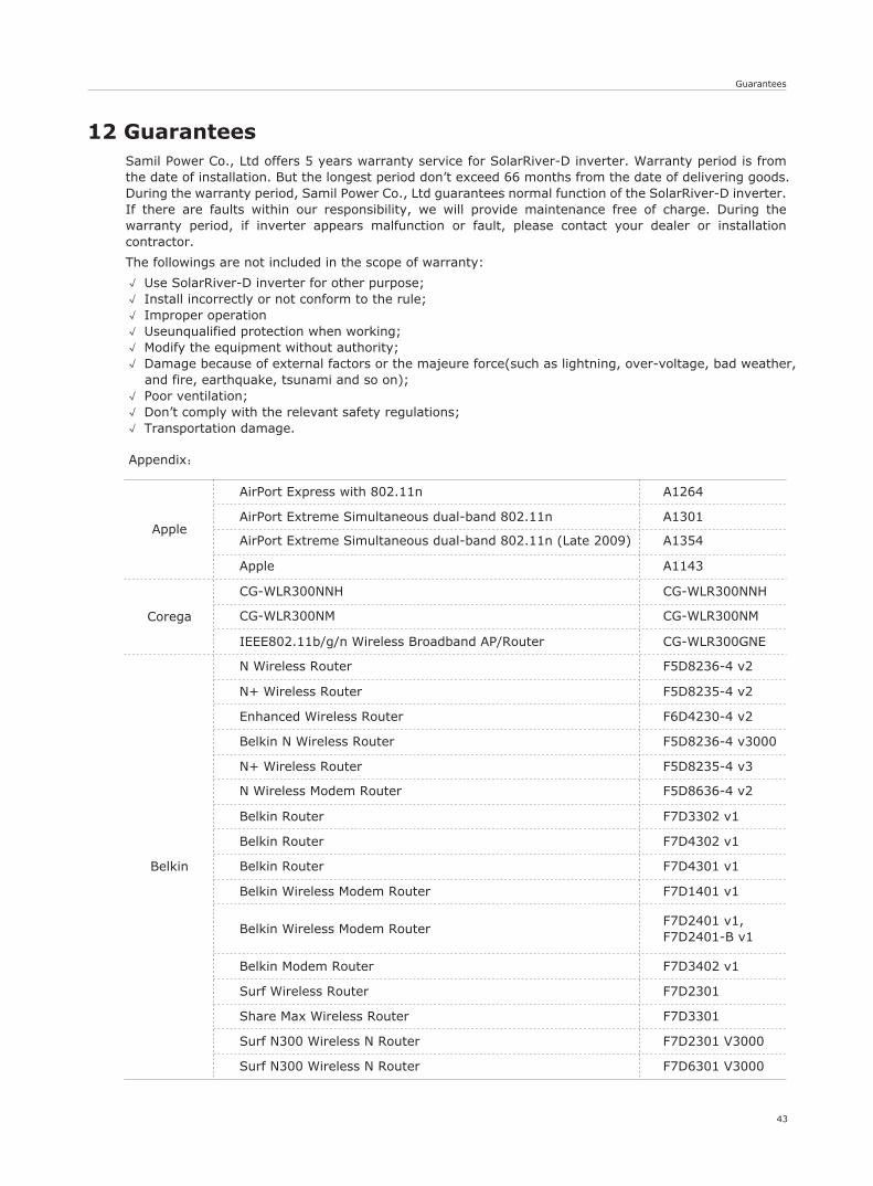
Appendix:
Apple
AirPort Express with 802.11n A1264
A1301AirPort Extreme Simultaneous dual-band 802.11n
AirPort Extreme Simultaneous dual-band 802.11n (Late 2009) A1354
Apple A1143
Corega
CG-WLR300NNH
CG-WLR300NM
CG-WLR300NNH
CG-WLR300NM
IEEE802.11b/g/n Wireless Broadband AP/Router CG-WLR300GNE
Belkin
N Wireless Router F5D8236-4 v2
N+ Wireless Router F5D8235-4 v2
Enhanced Wireless Router F6D4230-4 v2
Belkin N Wireless Router F5D8236-4 v3000
N+ Wireless Router F5D8235-4 v3
N Wireless Modem Router F5D8636-4 v2
Belkin Router F7D3302 v1
Belkin Router F7D4302 v1
Belkin Router F7D4301 v1
Belkin Wireless Modem Router F7D1401 v1
Belkin Wireless Modem RouterF7D2401 v1,F7D2401-B v1
Belkin Modem Router F7D3402 v1
Surf Wireless Router F7D2301
Share Max Wireless Router F7D3301
Surf N300 Wireless N Router F7D2301 V3000
Surf N300 Wireless N Router F7D6301 V3000
12 GuaranteesSamil Power Co., Ltd offers 5 years warranty service for SolarRiver-D inverter. Warranty period is from the date of installation. But the longest period don’t exceed 66 months from the date of delivering goods.During the warranty period, Samil Power Co., Ltd guarantees normal function of the SolarRiver-D inverter. If there are faults within our responsibility, we will provide maintenance free of charge. During the warranty period, if inverter appears malfunction or fault, please contact your dealer or installation contractor.
The followings are not included in the scope of warranty:
√ Use SolarRiver-D inverter for other purpose;√ Install incorrectly or not conform to the rule;√ Improper operation√ Useunqualified protection when working;√ Modify the equipment without authority;√ Damage because of external factors or the majeure force(such as lightning, over-voltage, bad weather,
and fire, earthquake, tsunami and so on);√ Poor ventilation;√ Don’t comply with the relevant safety regulations;√ Transportation damage.
44
Guarantees
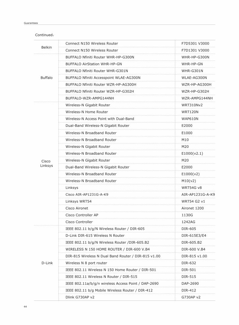
Continued:
Wireless-N Broadband Router E1000
Wireless-N Broadband Router M10
Wireless-N Gigabit Router M20
Wireless-N Broadband Router E1000(v2.1)
Wireless-N Gigabit Router M20
Dual-Band Wireless-N Gigabit Router E2000
Wireless-N Broadband Router E1000(v2)
Wireless-N Broadband Router M10(v2)
Linksys WRT54G v8
Cisco AIR-AP1231G-A-K9 AIR-AP1231G-A-K9
Linksys WRT54 WRT54 G2 v1
Cisco Aironet Aironet 1200
Cisco Controller AP 1130G
Cisco Controller 1242AG
D-Link
IEEE 802.11 b/g/N Wireless Router / DIR-605 DIR-605
D-Link DIR-615 Wireless N Router DIR-615E3/E4
IEEE 802.11 b/g/N Wireless Router /DIR-605.B2 DIR-605.B2
WIRELESS N 150 HOME ROUTER / DIR-600 V.B4 DIR-600 V.B4
DIR-815 Wireless N Dual Band Router / DIR-815 v1.00 DIR-815 v1.00
Wireless N 8 port router DIR-632
IEEE 802.11 Wireless N 150 Home Router / DIR-501 DIR-501
IEEE 802.11 Wireless N Router / DIR-515 DIR-515
IEEE 802.11a/b/g/n wireless Access Point / DAP-2690 DAP-2690
IEEE 802.11 b/g Mobile Wireless Router / DIR-412 DIR-412
Dlink G730AP v2 G730AP v2
BelkinConnect N150 Wireless Router F7D5301 V3000
Connect N150 Wireless Router F7D1301 V3000
Buffalo
BUFFALO Nfiniti Router WHR-HP-G300N WHR-HP-G300N
BUFFALO AirStation WHR-HP-GN WHR-HP-GN
BUFFALO Nfiniti Router WHR-G301N WHR-G301N
BUFFALO Nfiniti Accesspoint WLAE-AG300N WLAE-AG300N
BUFFALO Nfiniti Router WZR-HP-AG300H WZR-HP-AG300H
BUFFALO Nfiniti Router WZR-HP-G302H WZR-HP-G302H
BUFFALO-WZR-AMPG144NH WZR-AMPG144NH
Cisco Linksys
Wireless-N Gigabit Router WRT310Nv2
Wireless-N Home Router WRT120N
Wireless-N Access Point with Dual-Band WAP610N
Dual-Band Wireless-N Gigabit Router E2000
Guarantees
45
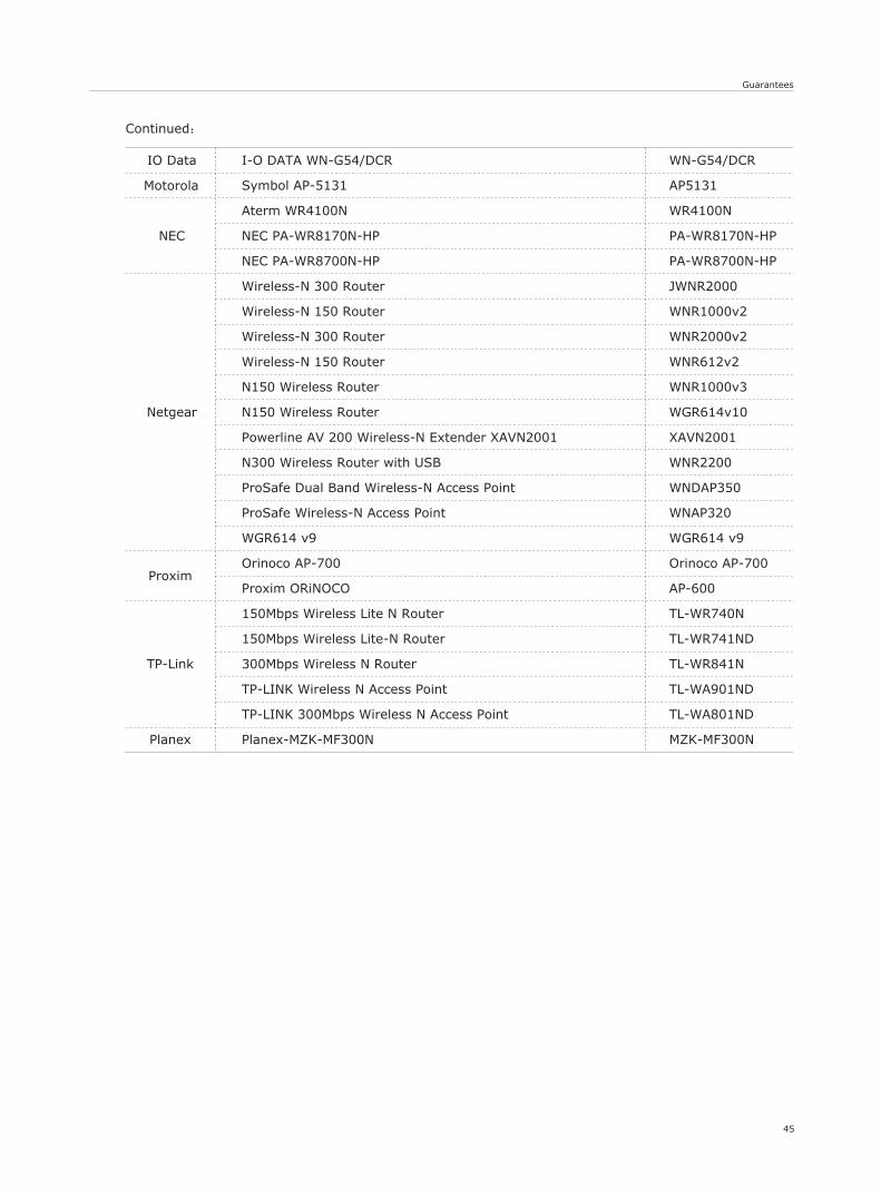
Continued:
IO Data I-O DATA WN-G54/DCR WN-G54/DCR
Motorola Symbol AP-5131 AP5131
NEC
Aterm WR4100N WR4100N
NEC PA-WR8170N-HP PA-WR8170N-HP
NEC PA-WR8700N-HP PA-WR8700N-HP
Netgear
Wireless-N 300 Router JWNR2000
Wireless-N 150 Router WNR1000v2
Wireless-N 300 Router WNR2000v2
Wireless-N 150 Router WNR612v2
N150 Wireless Router WNR1000v3
N150 Wireless Router WGR614v10
Powerline AV 200 Wireless-N Extender XAVN2001 XAVN2001
N300 Wireless Router with USB WNR2200
ProSafe Dual Band Wireless-N Access Point WNDAP350
ProSafe Wireless-N Access Point WNAP320
WGR614 v9 WGR614 v9
ProximOrinoco AP-700 Orinoco AP-700
Proxim ORiNOCO AP-600
TP-Link
150Mbps Wireless Lite N Router TL-WR740N
150Mbps Wireless Lite-N Router TL-WR741ND
300Mbps Wireless N Router TL-WR841N
TP-LINK Wireless N Access Point TL-WA901ND
TP-LINK 300Mbps Wireless N Access Point TL-WA801ND
Planex Planex-MZK-MF300N MZK-MF300N


Marketing & Sales Office
Add: No.52,Huigu Innovation Park, Huishan District, Wuxi,Jiangsu Province,P.R.China 214174
Tel: +86 510 83593131
Fax: +86 510 81819678
E-mail:[email protected]
http://www.samilpower.com
Factory
Add: No.66 Taihangshan Road,
Suyu Economic Development Zone, Suqian City,
Jiangsu Province, P.R.China 223800
Tel: +86 527 88754666
Fax: +86 527 84453877
SAMIL POWER CO., LTD.
Recommended