Robotics and Automation Applied Robotics and Automation Applied to Caltrans Highwaysto Caltrans Highways
Professor Bahram RavaniProfessor Bahram RavaniAdvanced Highway Maintenance and Construction Technology Advanced Highway Maintenance and Construction Technology
(AHMCT) Research Center(AHMCT) Research Center
A partnership between theA partnership between theUniversity of California University of California -- DavisDavis
and theand theCalifornia Department of TransportationCalifornia Department of Transportation

Page Page 22
RoboticsRobotics
Concept of robotics goes back to antiquity Concept of robotics goes back to antiquity Early mechanical robots can be traced to preEarly mechanical robots can be traced to pre--industrial revolutionindustrial revolutionModern terms and concepts were first introduced in Modern terms and concepts were first introduced in Theatrics and FictionTheatrics and FictionThe field has evolved due to integration of The field has evolved due to integration of computing, sensing, communication, and mechanical computing, sensing, communication, and mechanical design technologiesdesign technologiesMuch of the developments have occurred after World Much of the developments have occurred after World War II and since 1950War II and since 1950’’s s

Page Page 33
Antiquity and RoboticsAntiquity and Robotics
In the 18th book of Iliad (8th century B.C.), In the 18th book of Iliad (8th century B.C.), Homer describes servants that are built by Homer describes servants that are built by Vulcan for the service of Gods.Vulcan for the service of Gods.
These use wheels for mobility, are human These use wheels for mobility, are human shaped, are able to speak, and have some shaped, are able to speak, and have some intelligence. intelligence.

Page Page 44
Leonardo Leonardo dada VinciVinci’’s Wings Wing(15(15thth Century)Century)

Page Page 55
Japanese Maid (17Japanese Maid (17thth Century)Century)

Page Page 66
Automatic Writer by JaquetAutomatic Writer by Jaquet--Droz in 1760Droz in 1760

Page Page 77
TerminologyTerminology
The Word The Word RobotRobot::From Czech word Robota for forced labor or From Czech word Robota for forced labor or compulsory servicecompulsory service11stst appeared in appeared in ““RossumRossum’’s Universal Robots Universal Robot”” (R.U.R) a (R.U.R) a Czech play by Karel Capek ((pronounced Czech play by Karel Capek ((pronounced ““chopchop’’ekek”” ) ) R.U.R opened:R.U.R opened:
Prague 1921, New York 1922, London 1923Prague 1921, New York 1922, London 19231920 translation by P. Selver available as Penguin series from 1920 translation by P. Selver available as Penguin series from DoverDoverMore recent translation is contained in translation of a More recent translation is contained in translation of a collection of Capekcollection of Capek’’s writings called Towards the Radical s writings called Towards the Radical Center. Center.

Page Page 88

Page Page 99
TerminologyTerminologyIsaac Asimov (1920 Isaac Asimov (1920 –– 1992) introduced the term 1992) introduced the term robotics in his story Runaround published in 1942. robotics in his story Runaround published in 1942. Asimov is credited with popularizing the concept of Asimov is credited with popularizing the concept of robotics through a series of short stories about robots robotics through a series of short stories about robots starting with a story called starting with a story called ““A Strange PlayfellowA Strange Playfellow””which he wrote for Super Science Stories magazine. which he wrote for Super Science Stories magazine. This story is about a robot and its affection for a child This story is about a robot and its affection for a child that it is protecting. He later renamed this story that it is protecting. He later renamed this story calling it calling it ““RobbieRobbie””. . Asimov generated many other stories about robots Asimov generated many other stories about robots which are compiled into a book volume calledwhich are compiled into a book volume called““I, RobotI, Robot”” published in 1950 published in 1950

Page Page 1010
Asimov Asimov First Law: A robot may not injure a human First Law: A robot may not injure a human being, or, through inaction, allow a human being, or, through inaction, allow a human being to come to harm.being to come to harm.
Second Law: A robot may not injure a Second Law: A robot may not injure a human being, or, through inaction, allow a human being, or, through inaction, allow a human being to come to harm.human being to come to harm.
Third Law: A robot must protect its own Third Law: A robot must protect its own existence as long as such protection does existence as long as such protection does not conflict with the First or Second Law.not conflict with the First or Second Law.
Zeroth law: A robot may not injure Zeroth law: A robot may not injure humanity, or, through inaction, allow humanity, or, through inaction, allow humanity to come to harm.humanity to come to harm.

Page Page 1111
First Movie on RobotsFirst Movie on Robots
““MetropolisMetropolis”” from Fritz from Fritz Lang released in 1926. Lang released in 1926.
The female robot The female robot ““MariaMaria”” in the film is in the film is the first robot to be the first robot to be projected on a movie projected on a movie screen.screen.

Page Page 1212
George Lucas Movie: STAR WARSGeorge Lucas Movie: STAR WARS
Star Wars, 1977:, Introduces two robots:Star Wars, 1977:, Introduces two robots:R2R2--D2 and CD2 and C--3PO 3PO

Page Page 1313
Robot DefinitionsRobot Definitions
Robotics Institute of America (1975):An industrial Robotics Institute of America (1975):An industrial robot is a reprogrammable, multifunctional robot is a reprogrammable, multifunctional manipulator designed to move materials, parts, tools, manipulator designed to move materials, parts, tools, or specialized devices through variable programmed or specialized devices through variable programmed motions for the performance of a variety of tasks.motions for the performance of a variety of tasks.
WebsterWebster’’s Dictionary: A robot is an automatic s Dictionary: A robot is an automatic apparatus or device that performs functions ordinarily apparatus or device that performs functions ordinarily ascribed to humans or operates with what appears to ascribed to humans or operates with what appears to be almost human intelligence.be almost human intelligence.

Page Page 1414
Robot DefinitionsRobot DefinitionsISO (1988): ISO (1988): ““An industrial robot is an automatic, servoAn industrial robot is an automatic, servo--controlled, freely controlled, freely programmable, multipurpose manipulator, with several axes, for tprogrammable, multipurpose manipulator, with several axes, for the he handling of work pieces, tools or special devices. Variably proghandling of work pieces, tools or special devices. Variably programmed rammed operations make possible the execution of a multiplicity of taskoperations make possible the execution of a multiplicity of taskss””..
IFToMM (1991): A robot is a IFToMM (1991): A robot is a ““Mechanical system under automatic control Mechanical system under automatic control that performs operations such as handling and locomotionthat performs operations such as handling and locomotion””; and ; and Manipulator as Manipulator as ””Device for gripping and controlled movements of objectsDevice for gripping and controlled movements of objects””..
IEEE Community (2000): IEEE Community (2000): ““A robot is a machine constructed as an A robot is a machine constructed as an assemblage of joined links so that they can be articulated into assemblage of joined links so that they can be articulated into desired desired positions by a programmable controller and precision actuators tpositions by a programmable controller and precision actuators to perform o perform a variety of tasksa variety of tasks””..

Page Page 1515
Examples of Industrial Robots Examples of Industrial Robots (Adept Technology)(Adept Technology)

Control
Sensing
Preprocessing and Decision Making
Manipulation
Communication
ENVIRONMENT
Functional Block Diagram of a Robotic System

Page Page 1717
Control and
Coordination
Processing and
Decision Making
Communication
LocomotionExternal Sensing Manipulation
Material Handling System
Roadway
Operators
Functional Architecture of a Robotic System for Highway Maintenance Applications

Page Page 1818
First Highway ApplicationsFirst Highway Applications

Page Page 1919
Future Highway ApplicationsFuture Highway Applications

Page Page 2020
Tele-operations (Handling of Remote tasks)

Page Page 2121
Remote RoadwayRemote Roadway
Operations from inside the truck
Future: Operations from office / TMC

Page Page 2222
Remote DriversRemote Drivers

Page Page 2323
Tele-presence Transparent Operations for the Operator

Page Page 2424
Transparent RoadwayTransparent Roadway

Page Page 2525
Driver Assistance for Snow Plowing Driver Assistance for Snow Plowing Operations Operations

Page Page 2626
AutomationAutomation
Sensing (Conventional, GPS) and ActuationSensing (Conventional, GPS) and ActuationCAD & GISCAD & GISComputer Aided MetrologyComputer Aided MetrologyData Bases and Automatic SearchingData Bases and Automatic SearchingWeb Browser and Searches (IT)Web Browser and Searches (IT)

Page Page 2727
Conventional SensingConventional Sensing

Page Page 2828
Radar BasedRadar BasedCollision Warning SystemCollision Warning System

Page Page 2929
Driver Assist ComponentsDriver Assist Components

Page Page 3030
Difficulties Encountered:Difficulties Encountered:
Magnetic Sensing Components and Devices Magnetic Sensing Components and Devices were not Robust, Rugged, and Easy to Install were not Robust, Rugged, and Easy to Install and Maintain on Vehiclesand Maintain on Vehicles
Driving was difficult with HMIDriving was difficult with HMI

Page Page 3131
New Magnet SensingNew Magnet SensingSystem for the Snow PlowSystem for the Snow Plow
BenefitsBenefitsLower CostLower Cost(approx. factor of 10)(approx. factor of 10)Space & Wiring ReductionSpace & Wiring Reduction(approx. 50%(approx. 50%--75%)75%)Robust and Noise InsensitiveRobust and Noise Insensitive
AnalogInter ference
N Magnetometers
Digital Bit Stream3*N analog channels sampled at > 2*fc signal bandwidth
converted to serial bit stream
Digital Signal ProcessingUsing Field Programable Gate Array (FPGA)
Decode bitstream and determine vehicle lateral deviation
Digital communications channel(coaxial, twisted pair, fiber)
Next Generation Control Signal AcquisitionSystem
ControlSystem
(RS-232, RS-485, USB)
FPGA
Single Axis Magnetometer
Dual Axis Magnetometer

Page Page 3232
Physical architecture, including SoC Physical architecture, including SoC implementation of functional blocksimplementation of functional blocks
System-on-a-Chip (SOC) Implementation
Vehicle-HumanControl Algorithm
Radar ProcessingAlgorithm
Lateral DisplacmentAlgorithm
HMI DisplayAlgorithm
Modular SensorInterface
VehicleActuator(s)
DisplaySystem(s)
Radar
Intelligent Roadway Marker Sensing System
Steering Sensor
Speed Sensor
Other Sensors

Page Page 3333
Smart MagnetometerSmart Magnetometer

Page Page 3434
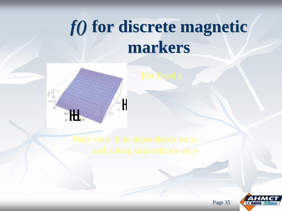
f()f() for discrete magnetic for discrete magnetic markersmarkers
For fixed x0 = 0HbL
0.1
0.2y HmL 0.2
0.4
z HmL-1-0.5
00.5
1
f
0.1
0.2y HmL
Implies need to constrain the( x , z ) domain
With restricted domainHLc
0.1
0.2y HmL0.45
0.475
0.5
0.525
0.55
z HmL-0.50
0.5f
0.1
0.2y HmLNote: very little dependence on z,
and strong dependence on y
Page Page 3535
f()f() for discrete magnetic for discrete magnetic markersmarkers
0
0.2
0.4x HmL 0.1
0.2
y HmL-0.50
0.5f
0
0.2
0.4x HmL
For fixed z
Note very little dependence on x,and strong dependence on y

Page Page 3636
Discrete Magnet Surface AnimationsDiscrete Magnet Surface AnimationsDriving along road Vehicle bounce
Lateral position,i.e. slide across magnet

Page Page 3737
Snowplowing Resistance ModelSnowplowing Resistance Model
sh
θ
Direction of travel
oh
δ
37

Page Page 3838
Comparison of the Results For Lateral Comparison of the Results For Lateral ForcesForces
( ) ( ) ( ) ( )( )( ) ( )2 2 21cos cos cos sin cos .lat s rfr p s a paF F N h v l h Lv−= θ = µ θ = µ ρ θ + δ θ +ρ θ
latrlat
FNAg
=ρ
,rlatN m
, /v km hr
Kaku’s model
Experimental data
Proposed model
0.27; 0.53sl s r−µ = µ =
Proposed model
0.33; 0.6sl s r−µ = µ =
38

Computer Based Metrology Computer Based Metrology and Reverse Engineeringand Reverse Engineering
Applications in Laser Based Scanning Applications in Laser Based Scanning and Measurementsand Measurements

Page Page 4040
Bridge Height and Profile Bridge Height and Profile MeasurementsMeasurements
Profile data needed for permitting and Profile data needed for permitting and homeland securityhomeland security
Data collection can be dangerous, Data collection can be dangerous, cause congestioncause congestion
Clearance data may be incomplete, Clearance data may be incomplete, inaccurate, difficult to maintain, inaccurate, difficult to maintain, difficult to accessdifficult to access
Several manual steps from data Several manual steps from data collection to database updatecollection to database update

Page Page 4141
SSTRUCTTRUCTVVIEWIEW and Block and Block DiagramDiagram

Page Page 4242
Scan GeometryScan Geometry

Page Page 4343
SSTRUCTTRUCTVVIEWIEW User ApplicationUser Application

Page Page 4444
Benchmarking of Laser Scanners for Benchmarking of Laser Scanners for Highway ApplicationsHighway Applications

Page Page 4545
TECHNOLOGY
Working principle of laser scanner
Typical Laser Scanner Triangulation Geometry

Page Page 4646
EXPERIMENTATION/TESTS
Control Test Scan Area – Old Hutch Rd, 500m of asphalt road surface
Point Acquisition & Surface
Precision/ NoiseAngular
Accuracy/Sampling Interval
Angular Resolution
Range Accuracy
Incidence & Coverage Angle

Page Page 4747
EXPERIMENTATION/TESTS (Contd.)
Pilot Test – 3D Scan of section of Highway 113 over Hutchison Rd
Pilot Test Scan Area – Bridge with clover-leaf ramps and specific geo-reference points at 25m, 50m and 100m on
either side
The specific goals for the Pilot Study are:•Collect a 360 degree scan from each scan location•Generate a Digital Terrain Model (DTM),•Generate contour lines depicting the low-lying areas.

Page Page 4848
TYPICAL RESULTS
Topographic map of State Highway 113 over Hutchison Drive

Page Page 4949
TYPICAL RESULTS (contd.)TYPICAL RESULTS
South bound clearance – point cloud and colors from real image
Real Colors from Scanner with lane stripes, shoulder, curb, gutter lines
Real Colors from Scanner with lane stripes, shoulder, curb, gutter lines

Page Page 5050
TYPICAL RESULTS (contd.)
Point cloud of Angular Accuracy test with computed translational (horizontal) error
Angular Accuracy TestTo test angular accuracy, 6” diameter spheres mounted on an L-Bracket alongside 3 in x 3 in square planar targets are given millimeter-level translation using a linear stage. This test is conducted for only two ranges—25 m and 75 m—and requires two scans. The scans will be from the same scanner location, with a change in the target location provided by the linear translation stage.

Page Page 5151
TYPICAL RESULTS (contd.)
Line of sight of 3D Laser Scanner – For
edge effects
Surface Precision and Noise Acquisition TestThe fixture is a stair-type pattern on an 18 in x 12 in x 1.5 in thick precisely-machined aluminum block with the step-height varying from 0.02 in to ~ 5/8 in. One of these targets will be placed at each of the following ranges: 25 m, 50 m, 75 m and 100 m.

Page Page 5252
TYPICAL RESULTS (contd.)
@ 25 m
@ 50 m
@ 75 m
@ 100 m

Page Page 5353
TYPICAL RESULTS (contd.)
Leica (m) Trimble (m) Optech (m)
White (25m) 0.005 0.006 0.007
Black (25m) 0.011 0.007 0.008
Grey (25m) 0.009 0.011 0.012
White (50m) 0.006 0.007 0.007
Black (50m) 0.013 0.009 0.011
Grey (50m) 0.011 0.012 0.013
White (75m) 0.008 0.008 0.009
Black (75m) 0.017 0.011 0.012
Grey (75m) 0.012 0.013 0.014
White (100m) 0.011 0.010 0.011
Black (100m) 0.021 0.014 0.016
Grey (100m) 0.019 0.019 0.021
Measured noise of Laser Point Cloud Data in meters

Page Page 5454
TYPICAL RESULTS (contd.)
Range Accuracy TestThe test component is two 10 in x 10 in anodized flat aluminum plates with gray dull finish (reflectivity ~ 40%) and black dull finish (reflectivity ~8%) respectively, mounted on a 40 in x 20 in aluminum plate. Test ranges are 25 m, 50 m, 75 m and 100 m.
Range Errors plotted with interpolated surface and laser point cloud

Page Page 5555
TYPICAL RESULTS (contd.)
Angular Resolution TestTo test the ability of a scanner to resolve small objects, special target boxes are to be scanned at four ranges: 25 m, 50 m, 75 m and 100 m. These 24 in x 24 in boxes have a front panel containing tapered slots decreasing from about 2.5 in wide at the periphery to about 0.1 in at the center.

Page Page 5656
Time
Visualization Capabilities
Manual drafting
Networked mapping
GIS, computer mapping, SYMAPGIS, 3D perspective, SYMVU
KML Viewer, e.g. Google Earth
1950 1970 1980 2000
CAD/GIS, GPS, Visualization CAD/GIS, GPS, Visualization
1960 1990
GPS, public use
2010
Desktop mapping
Visualization has been moving towards a client that is:3D + networked + collaborative + integrated

Page Page 5757
Geographic Information System (GIS)Geographic Information System (GIS)Consists of Spatial and NonConsists of Spatial and Non--spatial spatial DataData
Spatial data refers to geographic areas Spatial data refers to geographic areas or features. Features occupies a or features. Features occupies a location. location. NonNon--spatial data has no specific spatial data has no specific location in space, but have a location in space, but have a geographic component and be linked geographic component and be linked to a geographic location.to a geographic location.
ThemesThemesThemes link features with their Themes link features with their attributes attributes Themes are linked by geography Themes are linked by geography
Collections of themes form a GIS Collections of themes form a GIS database database

Page Page 5858
Data ModelsData ModelsVector modelVector model
information about points, information about points, lines, and polygons, e.g. lines, and polygons, e.g. roads & highwaysroads & highwaysencoded and stored as a encoded and stored as a collection of collection of x,yx,y coordinates coordinates
Raster ModelRaster Modelmodels continuous features models continuous features a collection of grid cells a collection of grid cells e.g. aerial photo
Raster
Vector
Real Worlde.g. aerial photo

Page Page 5959
GIS ApplicationsGIS ApplicationsData stored in a databaseData stored in a databaseAllows for spatial analysisAllows for spatial analysis----e.g. spatial queriese.g. spatial queriesEnable data visualization of Enable data visualization of selected spatial and nonselected spatial and non--spatial data to:spatial data to:
solve complex problemssolve complex problemsview status and trendsview status and trendstrack assetstrack assetstrack vehiclestrack vehiclesdecision supportdecision support

Page Page 6060
Global Position System (GPS)Global Position System (GPS)Consists of 3 Segments: Consists of 3 Segments: Space Segment:Space Segment:
30 GPS Satellites (6 30 GPS Satellites (6 spares) in 6 orbital spares) in 6 orbital planes, 55 degree planes, 55 degree inclinationsinclinations20,200 km, 12 hrs orbits 20,200 km, 12 hrs orbits

Page Page 6161
GPS Control SegmentGPS Control SegmentMaster Control Station (MCS)Master Control Station (MCS)
located in the Consolidated Space Operations Center (CSOC) at Sclocated in the Consolidated Space Operations Center (CSOC) at Schriever Air Force hriever Air Force Base (SAFB), CO. Base (SAFB), CO. manned 24 hours per day, 7 days per week manned 24 hours per day, 7 days per week GPS ephemeris being a tabulation of computed positions, velocitiGPS ephemeris being a tabulation of computed positions, velocities and derived right es and derived right ascension and declination of GPS satellites at specific times, rascension and declination of GPS satellites at specific times, replace "position" with eplace "position" with "ephemeris" "ephemeris" The prediction data is upThe prediction data is up--linked, or transmitted, to the satellites for transmission back linked, or transmitted, to the satellites for transmission back to to the users. the users. The control segment also ensures that the GPS satellite orbits aThe control segment also ensures that the GPS satellite orbits and clocks remain within nd clocks remain within acceptable limits. acceptable limits.
Monitor StationsMonitor StationsSix monitor stationsSix monitor stationsEach monitor the exact altitude, position, Each monitor the exact altitude, position, speed, and overall health of the satellites. speed, and overall health of the satellites.
Ground Antennas: Ground Antennas: Monitor and track the satellites.Monitor and track the satellites.Transmit correction information Transmit correction information to individual satellites. to individual satellites.
GPS Control Segment Locations

Page Page 6262
User SegmentUser SegmentConsists of antenna for Consists of antenna for receiving GPS satellite receiving GPS satellite signals,signals,And a GPS receiver for And a GPS receiver for collecting navigation collecting navigation data and for calculating data and for calculating time and locationtime and location

Page Page 6363
GPS OperationGPS Operation

Page Page 6464
DGPS Accuracy ComparisonDGPS Accuracy ComparisonNo No DifferentialDifferential BeaconBeacon OmnistarOmnistar WAASWAAS Omnistar HPOmnistar HP
Latitude Standard Latitude Standard Deviation (m)Deviation (m) 1.491.49 0.350.35 0.390.39 0.380.38 0.050.05Longitude Standard Longitude Standard Deviation (m)Deviation (m) 1.131.13 0.270.27 0.310.31 0.300.30 0.060.06Elevation Standard Elevation Standard Deviation (m)Deviation (m) 3.233.23 0.750.75 0.650.65 0.780.78 0.120.12Latitude Range (m)Latitude Range (m) 15.9815.98 5.865.86 3.673.67 7.747.74 0.570.57Longitude Range (m)Longitude Range (m) 14.4714.47 3.973.97 2.412.41 4.774.77 0.540.54Elevation Range (m)Elevation Range (m) 35.2935.29 9.119.11 5.555.55 14.9314.93 1.201.20% Time without % Time without differentialdifferential 100.00100.00 0.090.09 0.000.00 0.050.05 0.000.00

Page Page 6565
Example of GIS/GPS IntegrationExample of GIS/GPS Integration

Page Page 6666
GPSConstellation
Arm Based
Processor
RS232NEMA
GPS Receiver LCD Display
/ HMI Digital Input
Power input
On-Board Flash Storage
On-Board SDRAM
MEMSAccelerometer
Temperature Sensor
Wireless Data Communication
Clock
-
NiMH Battery
PowerElectronics
ZigbeeWireless
MEMS Gyro
ODB II Interface
VehicularVersion Only
Zigbee Wireless OBD-II Interface
GPS-Advanced Travel Diary System

Page Page 6767
Goals of Travel SurveysGoals of Travel SurveysProvide data to calibrate regional models and travel demand modeProvide data to calibrate regional models and travel demand modelslsDevelop travel demand models to forecast future demand Develop travel demand models to forecast future demand Predict the number of trips generated by households as a functioPredict the number of trips generated by households as a function of n of demographics, socioeconomics, and location relative to employmendemographics, socioeconomics, and location relative to employment t and commercial centers and commercial centers Estimate travel mode choice and traffic volumes on various roadsEstimate travel mode choice and traffic volumes on various roadsAssess the impact of changes in transportation policy or the Assess the impact of changes in transportation policy or the transportation systemtransportation systemPredict emissions from motor vehicles and input for air quality Predict emissions from motor vehicles and input for air quality analysisanalysisThus, enhance transportation planning with improved knowledge ofThus, enhance transportation planning with improved knowledge oftraveler behaviortraveler behaviorDepartment of Transportation, State, County, and City planners wDepartment of Transportation, State, County, and City planners will ill use data and models for infrastructure planning and deploymentuse data and models for infrastructure planning and deployment

Page Page 6868
System ArchitectureSystem ArchitecturePhase I: Data Collection Phase II: Post-Processing
T1
T2
T3
TN
GPS-TDVehicular
Units
T1
T2
T3
TN
GPS-TDPersonal
Units
Results Data
Analysis
GIS Database
Data Format
Conversion
Data Visualization
XML, DBF, TXT, etc.
Current project Future: Data analysis automation

Page Page 6969
GPS ModuleZigBee
WirelessGyro &
AccelerometerGPS RF
SDRAM CPU 256MB NAND FlashUSB
6-layer board130 components470 parts

Page Page 7070Power Supplies

Page Page 7171
Project ObjectivesProject ObjectivesTo reduce the userTo reduce the user--burden of traditional diaries burden of traditional diaries that has resulted in the participantsthat has resulted in the participants’’ omission omission of trips.of trips.To provide activityTo provide activity--timetime--space diaries showing the space diaries showing the relationship between trips, land use activities, and relationship between trips, land use activities, and time.time.To collect accurate and reliable travel behavior To collect accurate and reliable travel behavior information to support planning models and other information to support planning models and other analysis.analysis.Overcome challenges and pitfalls encountered in Overcome challenges and pitfalls encountered in previous GPSprevious GPS--aided longitudinal travel surveys aided longitudinal travel surveys
Long GPS startup timeLong GPS startup timeGPS outage in Urban Canyons and under tree canopiesGPS outage in Urban Canyons and under tree canopiesHardware robustnessHardware robustness

Page Page 7272
Example of GPS, GIS, Data Bases, Example of GPS, GIS, Data Bases, and Visualization Integrationand Visualization Integration

Page Page 7373
Time
Modeling Capabilities
Assembly language programmingHigher level languages, e.g. Fortran
Structured languages, e.g. Pascal, C
Relational databases
Object orientated, e.g. Java, C sharp
Semantic modeling
1950 1970 1980 2000
Modeling Capabilities Over TimeModeling Capabilities Over Time
1960 1990
Developers have been performing ad-hoc domain modeling for a long time.
2010
Semantic modeling is essentially strong OO modeling without the implementation (methods)

Roadside Inventory Stand-alone Visualization Architecture – Working Prototype
DemonstratedStand-alone System
Existing DatabaseBackend
(MS Access)
Existing DatabaseFrontend
(MS Access)
Culvert View Application
KML Visual Reports
KML Visual Report
In-field Use
Distributed via email,
network, etc.
Visual Report
KML Client (Google Earth, ArcGIS Explorer)

Page Page 7575
KML Browsers
Persistentstorage
KML Server
Existing relational database
Semantic Model
Semantic queries
Roadside Inventory Digital Roadside Inventory Digital ArchitectureArchitecture
Visualization… …Semantic Models
• Google Earth• ESRI ArcGIS Explorer
RDF Adapter
Static and dynamic data
In-field UseStatic KML
Report

Page Page 7676
Roadside InventoryRoadside InventoryTerrain Model + CulvertsTerrain Model + Culverts
Placemark style indicates flow direction

Page Page 7777
Visualization Across Three DomainsVisualization Across Three DomainsPhysical SpaceTime+ +
Visualization is supported by semantic & relational queries on back-end.

Page Page 7878
Vehicle LocationVehicle LocationRealReal--time and Historic GPS Sensor Datatime and Historic GPS Sensor Data
Dynamic layer

Page Page 7979
Dynamic VisualizationDynamic VisualizationMultiMulti--resolution GPS Dataresolution GPS Data
Visual data is a function of viewer
altitude & orientation

Page Page 8080
Traffic VisualizationTraffic VisualizationRealReal--time Speed, Occupancy, Flowtime Speed, Occupancy, Flow

Page Page 8181
Doppler Radar Terrain OverlaysDoppler Radar Terrain OverlaysRealReal--time and Historic, Radar Loopstime and Historic, Radar Loops
http://fish.ahmct.ucdavis.edu/assetman/ahmct-assetman.kmz

Page Page 8282
Asset PropertiesAsset PropertiesVisual Culvert Condition ReportVisual Culvert Condition Report

Page Page 8383
Assets Details in ContextAssets Details in ContextProperties Geo & Time Referenced Photos
Application links

Page Page 8484
Culvert Inventory VisualizationCulvert Inventory VisualizationStatic LayerStatic Layer
Facilitates data validation

Page Page 8585
Traffic Cam OverlaysTraffic Cam OverlaysRealReal--time and historictime and historic

Page Page 8686
FutureFuture

Page Page 8787
Digital ModelDigital Model--Based Planning & AutomationBased Planning & Automation
Digital Model
Human-Controlled & Automated Equipment:Machine-Guided Systems, Sensing, and Robotics
Codes &Standards
Planning Surveying GeometricDesign
EngineeringAnalysis
Verification,Performance Evaluation,
Quality Assessment
SitePreparation &Construction
ConstructionPlanning &Budgeting
OperationalPlanning
Inspection,Rehabilitation
Planning
Maintenance,Repair, &Retrofit
Layer 1
Layer 2
Layer 3
Recommended