RIVAS
SCP0-GA-2010-265754
rivas_db_wp1_d1_2_v04_measuring_protocol Page 1 of 25 13/10/2011
RIVAS
Railway Induced Vibration Abatement Solutions
Collaborative project
Protocol for free field measurements of mitigation effects
in the project RIVAS for WP2,3,4,5
Deliverable D1.2
Submission date: 13/10/2011
Project Coordinator:
Bernd Asmussen
International Union of Railways (UIC)
RIVAS
SCP0-GA-2010-265754
rivas_db_wp1_d1_2_v04_measuring_protocol Page 2 of 25 13/10/2011
Title Protocol for free field measurements of mitigation effects in the project RIVAS for WP 2, 3, 4, 5
Domain WP 1.2
Date
Author/Authors Dorothée Stiebel (DB) Partner DB, SBB, SNCF, Trafikverket, Vibratec, ISVR, BT, RATP, KUL, CSTB,
Cedex , Adif, BAM
Document Code rivas_db_wp1_d1_2_v04_measuring_protocol Version 4 Status Final
Dissemination level:
Document history
Revision Date Description
1 13/7/2011 First Draft
2 10/8/2011 Second Draft
3 8/9/2011 Third Draft
4 13/10/2011 Final
Project co-funded by the European Commission within the Seventh Framework Programme
Dissemination Level PU Public X PP Restricted to other programme participants (including the Commission Services) RE Restricted to a group specified by the consortium (including the Commission) Services) CO Confidential, only for members of the consortium (including the Commission Services)

RIVAS
SCP0-GA-2010-265754
rivas_db_wp1_d1_2_v04_measuring_protocol Page 3 of 25 13/10/2011
1. EXECUTIVE SUMMARY
Developed within the RIVAS project, the measuring protocol describes how to perform free-field measurements to assess the efficiency of vibration-mitigation measures at railway lines. Besides the description of the measuring procedure, the deliverable includes also requirements for the test equipment, the measuring site selection and the vibration measurement. The aim of the measuring protocol is to ensure the comparability of results obtained by different partners.
RIVAS
SCP0-GA-2010-265754
rivas_db_wp1_d1_2_v04_measuring_protocol Page 4 of 25 13/10/2011
2. TABLE OF CONTENTS
1. Executive Summary .......................................................................................................... 3
2. Table of contents ............................................................................................................... 4
3. Chapters............................................................................................................................. 5
3.1 Introduction ............................................................................................................... 5
3.2 Vibrations Generation and Reduction ....................................................................... 6
3.3 Measuring Procedure................................................................................................. 8
3.4 Selection of a Measuring Site.................................................................................. 10
3.5 Test Specification.................................................................................................... 11
3.6 Test Equipment ....................................................................................................... 12
3.7 Vibration Measurements ......................................................................................... 12
3.8 Vibration Data Analysis .......................................................................................... 14
3.9 Further Measurements............................................................................................. 16
3.10 Documentation ........................................................................................................ 16
3.11 Reference Conditions .............................................................................................. 17
4. References ....................................................................................................................... 18
Attachment: Database Structure.............................................................................................. 19
Attachment: Templates ........................................................................................................... 20
RIVAS
SCP0-GA-2010-265754
rivas_db_wp1_d1_2_v04_measuring_protocol Page 5 of 25 13/10/2011
3. CHAPTERS
3.1 INTRODUCTION
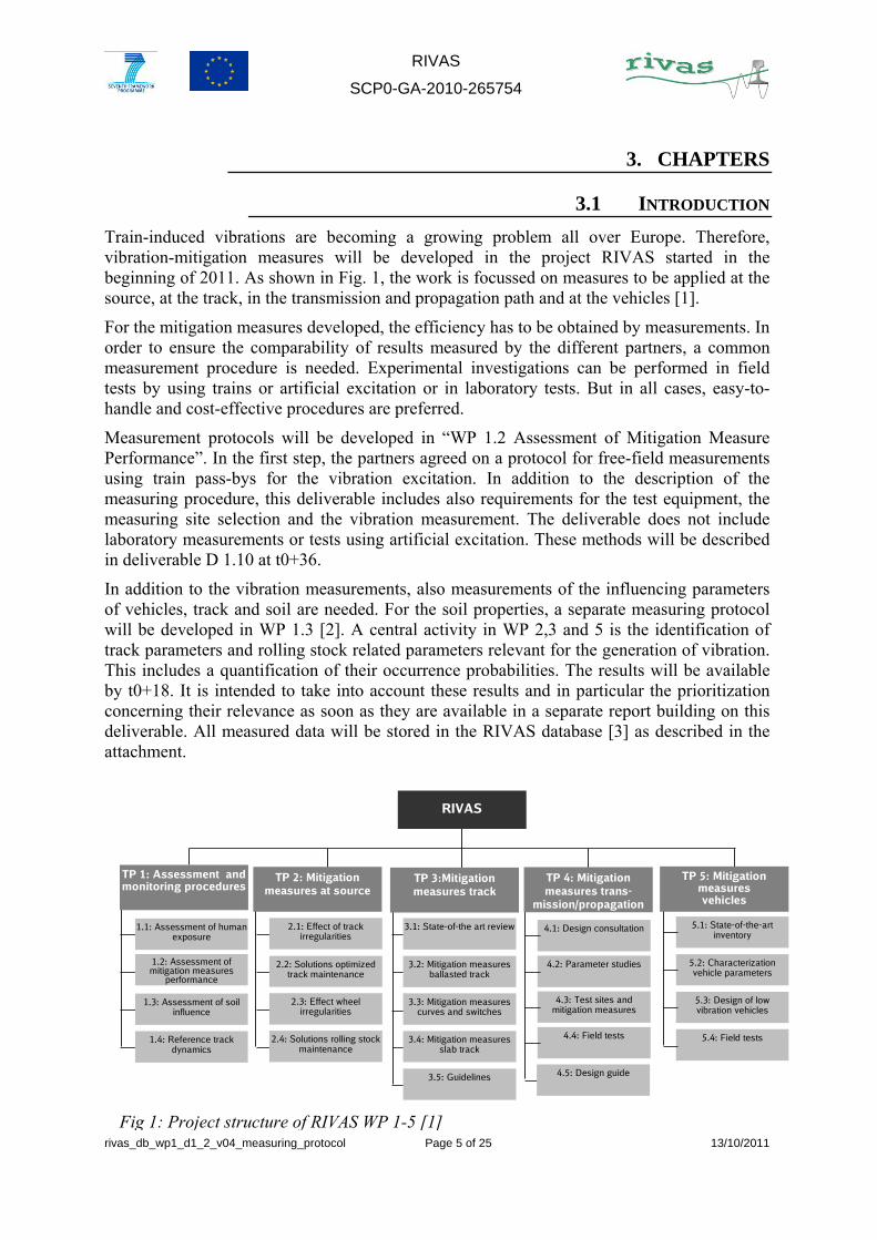
Train-induced vibrations are becoming a growing problem all over Europe. Therefore, vibration-mitigation measures will be developed in the project RIVAS started in the beginning of 2011. As shown in Fig. 1, the work is focussed on measures to be applied at the source, at the track, in the transmission and propagation path and at the vehicles [1].
For the mitigation measures developed, the efficiency has to be obtained by measurements. In order to ensure the comparability of results measured by the different partners, a common measurement procedure is needed. Experimental investigations can be performed in field tests by using trains or artificial excitation or in laboratory tests. But in all cases, easy-to-handle and cost-effective procedures are preferred.
Measurement protocols will be developed in “WP 1.2 Assessment of Mitigation Measure Performance”. In the first step, the partners agreed on a protocol for free-field measurements using train pass-bys for the vibration excitation. In addition to the description of the measuring procedure, this deliverable includes also requirements for the test equipment, the measuring site selection and the vibration measurement. The deliverable does not include laboratory measurements or tests using artificial excitation. These methods will be described in deliverable D 1.10 at t0+36.
In addition to the vibration measurements, also measurements of the influencing parameters of vehicles, track and soil are needed. For the soil properties, a separate measuring protocol will be developed in WP 1.3 [2]. A central activity in WP 2,3 and 5 is the identification of track parameters and rolling stock related parameters relevant for the generation of vibration. This includes a quantification of their occurrence probabilities. The results will be available by t0+18. It is intended to take into account these results and in particular the prioritization concerning their relevance as soon as they are available in a separate report building on this deliverable. All measured data will be stored in the RIVAS database [3] as described in the attachment.
RIVAS
1.1: Assessment of human exposure
1.2: Assessment of mitigation measures
performance
1.3: Assessment of soil influence
1.4: Reference track dynamics
2.1: Effect of track irregularities
2.2: Solutions optimized track maintenance
2.3: Effect wheel irregularities
2.4: Solutions rolling stock maintenance
3.5: Guidelines
3.1: State-of-the art review
3.2: Mitigation measures ballasted track
3.3: Mitigation measures curves and switches
3.4: Mitigation measures slab track
TP 1: Assessment and monitoring procedures
TP 2: Mitigation measures at source
TP 3:Mitigation measures track
4.1: Design consultation
4.2: Parameter studies
4.3: Test sites and mitigation measures
4.4: Field tests
4.5: Design guide
5.1: State-of-the-art inventory
5.2: Characterization vehicle parameters
5.3: Design of low vibration vehicles
5.4: Field tests
TP 5: Mitigation measures vehicles
TP 4: Mitigation measures trans-
mission/propagation
Fig 1: Project structure of RIVAS WP 1-5 [1]
RIVAS
SCP0-GA-2010-265754
rivas_db_wp1_d1_2_v04_measuring_protocol Page 6 of 25 13/10/2011
3.2 VIBRATIONS GENERATION AND REDUCTION
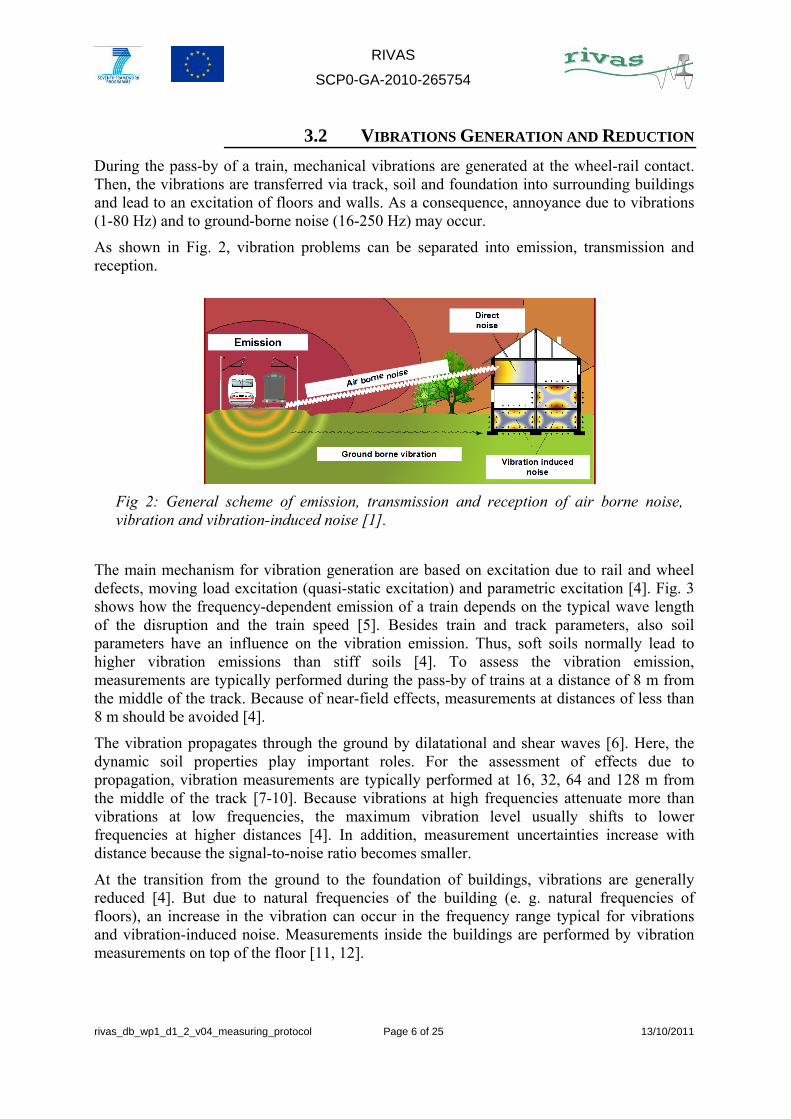
During the pass-by of a train, mechanical vibrations are generated at the wheel-rail contact. Then, the vibrations are transferred via track, soil and foundation into surrounding buildings and lead to an excitation of floors and walls. As a consequence, annoyance due to vibrations (1-80 Hz) and to ground-borne noise (16-250 Hz) may occur.
As shown in Fig. 2, vibration problems can be separated into emission, transmission and reception.
The main mechanism for vibration generation are based on excitation due to rail and wheel defects, moving load excitation (quasi-static excitation) and parametric excitation [4]. Fig. 3 shows how the frequency-dependent emission of a train depends on the typical wave length of the disruption and the train speed [5]. Besides train and track parameters, also soil parameters have an influence on the vibration emission. Thus, soft soils normally lead to higher vibration emissions than stiff soils [4]. To assess the vibration emission, measurements are typically performed during the pass-by of trains at a distance of 8 m from the middle of the track. Because of near-field effects, measurements at distances of less than 8 m should be avoided [4].
The vibration propagates through the ground by dilatational and shear waves [6]. Here, the dynamic soil properties play important roles. For the assessment of effects due to propagation, vibration measurements are typically performed at 16, 32, 64 and 128 m from the middle of the track [7-10]. Because vibrations at high frequencies attenuate more than vibrations at low frequencies, the maximum vibration level usually shifts to lower frequencies at higher distances [4]. In addition, measurement uncertainties increase with distance because the signal-to-noise ratio becomes smaller.
At the transition from the ground to the foundation of buildings, vibrations are generally reduced [4]. But due to natural frequencies of the building (e. g. natural frequencies of floors), an increase in the vibration can occur in the frequency range typical for vibrations and vibration-induced noise. Measurements inside the buildings are performed by vibration measurements on top of the floor [11, 12].
Fig 2: General scheme of emission, transmission and reception of air borne noise, vibration and vibration-induced noise [1].

RIVAS
SCP0-GA-2010-265754
rivas_db_wp1_d1_2_v04_measuring_protocol Page 7 of 25 13/10/2011
In the next step, the known influencing parameters will be summarized [4,13,14]. For vibration emission, the following parameters are considered to have important influences:
Component Parameter
Vehicle Train speed, mass and stiffness of vehicle components, distance between adjacent wheels, out-of-roundness of the wheels
Track Track stiffness, type of resilient element (e. g. rail pads), sleeper type and distance, track irregularities (track geometry, rail corrugation, hanging sleeper),
Soil (below track)
Input impedance
Tab. 1: Influencing parameters for the vibration emission
As shown in Fig. 3, excitations caused by rail roughness (with wavelengths less than 0.1 m) are only important if trains are running at a rather low speed at a rail with long-pitched corrugations but longer wavelength track unevenness as measured e. g. by track recording vehicles is important.
Fig. 3: Correlation between the disruption wavelength, the train velocity and the resulting frequency of the vibration for typical vibration-inducing disruptions [5].
RIVAS
SCP0-GA-2010-265754
rivas_db_wp1_d1_2_v04_measuring_protocol Page 8 of 25 13/10/2011
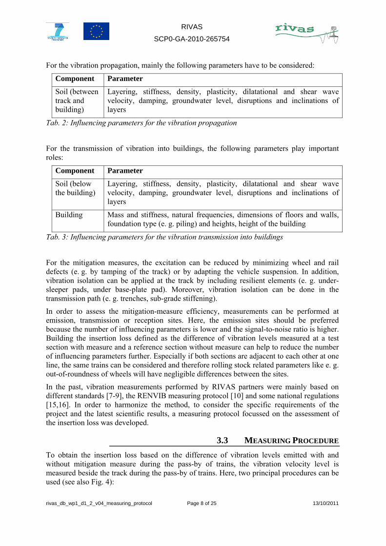
For the vibration propagation, mainly the following parameters have to be considered:
Component Parameter
Soil (between track and building)
Layering, stiffness, density, plasticity, dilatational and shear wave velocity, damping, groundwater level, disruptions and inclinations of layers
Tab. 2: Influencing parameters for the vibration propagation
For the transmission of vibration into buildings, the following parameters play important roles:
Component Parameter
Soil (below the building)
Layering, stiffness, density, plasticity, dilatational and shear wave velocity, damping, groundwater level, disruptions and inclinations of layers
Building Mass and stiffness, natural frequencies, dimensions of floors and walls, foundation type (e. g. piling) and heights, height of the building
Tab. 3: Influencing parameters for the vibration transmission into buildings
For the mitigation measures, the excitation can be reduced by minimizing wheel and rail defects (e. g. by tamping of the track) or by adapting the vehicle suspension. In addition, vibration isolation can be applied at the track by including resilient elements (e. g. under-sleeper pads, under base-plate pad). Moreover, vibration isolation can be done in the transmission path (e. g. trenches, sub-grade stiffening).
In order to assess the mitigation-measure efficiency, measurements can be performed at emission, transmission or reception sites. Here, the emission sites should be preferred because the number of influencing parameters is lower and the signal-to-noise ratio is higher. Building the insertion loss defined as the difference of vibration levels measured at a test section with measure and a reference section without measure can help to reduce the number of influencing parameters further. Especially if both sections are adjacent to each other at one line, the same trains can be considered and therefore rolling stock related parameters like e. g. out-of-roundness of wheels will have negligible differences between the sites.
In the past, vibration measurements performed by RIVAS partners were mainly based on different standards [7-9], the RENVIB measuring protocol [10] and some national regulations [15,16]. In order to harmonize the method, to consider the specific requirements of the project and the latest scientific results, a measuring protocol focussed on the assessment of the insertion loss was developed.
3.3 MEASURING PROCEDURE
To obtain the insertion loss based on the difference of vibration levels emitted with and without mitigation measure during the pass-by of trains, the vibration velocity level is measured beside the track during the pass-by of trains. Here, two principal procedures can be used (see also Fig. 4):
RIVAS
SCP0-GA-2010-265754
rivas_db_wp1_d1_2_v04_measuring_protocol Page 9 of 25 13/10/2011
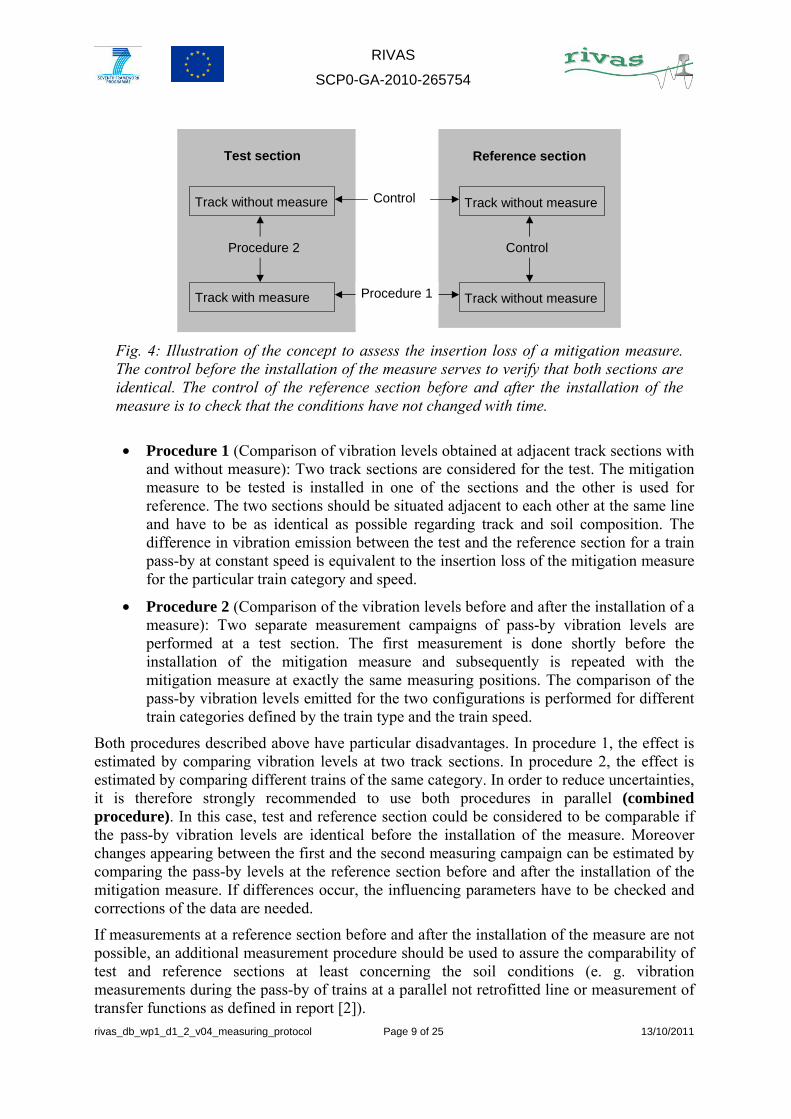
• Procedure 1 (Comparison of vibration levels obtained at adjacent track sections with and without measure): Two track sections are considered for the test. The mitigation measure to be tested is installed in one of the sections and the other is used for reference. The two sections should be situated adjacent to each other at the same line and have to be as identical as possible regarding track and soil composition. The difference in vibration emission between the test and the reference section for a train pass-by at constant speed is equivalent to the insertion loss of the mitigation measure for the particular train category and speed.
• Procedure 2 (Comparison of the vibration levels before and after the installation of a measure): Two separate measurement campaigns of pass-by vibration levels are performed at a test section. The first measurement is done shortly before the installation of the mitigation measure and subsequently is repeated with the mitigation measure at exactly the same measuring positions. The comparison of the pass-by vibration levels emitted for the two configurations is performed for different train categories defined by the train type and the train speed.
Both procedures described above have particular disadvantages. In procedure 1, the effect is estimated by comparing vibration levels at two track sections. In procedure 2, the effect is estimated by comparing different trains of the same category. In order to reduce uncertainties, it is therefore strongly recommended to use both procedures in parallel (combined procedure). In this case, test and reference section could be considered to be comparable if the pass-by vibration levels are identical before the installation of the measure. Moreover changes appearing between the first and the second measuring campaign can be estimated by comparing the pass-by levels at the reference section before and after the installation of the mitigation measure. If differences occur, the influencing parameters have to be checked and corrections of the data are needed.
If measurements at a reference section before and after the installation of the measure are not possible, an additional measurement procedure should be used to assure the comparability of test and reference sections at least concerning the soil conditions (e. g. vibration measurements during the pass-by of trains at a parallel not retrofitted line or measurement of transfer functions as defined in report [2]).
Test section Reference section
Track without measure
Track with measure
Track without measure
Track without measure
Control
Control
Procedure 1
Procedure 2
Fig. 4: Illustration of the concept to assess the insertion loss of a mitigation measure. The control before the installation of the measure serves to verify that both sections are identical. The control of the reference section before and after the installation of the measure is to check that the conditions have not changed with time.
RIVAS
SCP0-GA-2010-265754
rivas_db_wp1_d1_2_v04_measuring_protocol Page 10 of 25 13/10/2011
At a given site, the measured vibration level depends mainly on the train category defined by the train type (depending on the train parameters as distance between adjacent wheels, mass and stiffness of train components, loads) and the train speed. Due to differences especially in the wheel conditions, differences may occur considering different trains of the same category. To reduce the uncertainties in the resulting vibrations, data obtained during the pass-by of trains belonging to the same category and having comparable speeds have to be averaged. This is especially important for using the measuring procedure 2. Whether a simple categorisation of trains in high-speed trains, regional trains and freight trains is possible has to be investigated in more detail.
Specific requirements for the RIVAS project:
• For the test of measures at the source in WP 2, the combined procedure should be used regarding a test section with optimized track maintenance and a reference section with normal track maintenance. Initially, the track at the test and the reference section should be in the same condition. It may be necessary for tamping to be carried out at the beginning of the investigation. For the investigation of vehicle maintenance measures, procedure 2 should be used.
• Mitigation measures at the track as developed in WP 3 should be also measured by using the combined procedure regarding a test section with and a reference section without mitigation measure. If tamping is needed to restore the track alignment after the installation of a measure, the reference section should be treated identically to the test section. If possible the track geometry should be measured to determine track unevenness before and after installation of the mitigation measure. Vibration reduction measures particularly devoted to curves and switches will generally not allow finding a corresponding reference section. In these cases, procedure 2 has to be used.
• For measures situated in the transmission path as developed in WP 4, the combined procedure should be used with measurements before and after the installation of the measure.
• For mitigation measures at vehicles as planned in WP 5, procedure 2 has to be used. At the test section, test trains consisting of vibration-optimised vehicles and of normal vehicles are measured during the pass-by.
3.4 SELECTION OF A MEASURING SITE
For the selection of an adequate measuring site, the following requirements have to be considered. Both, test and reference section should have a length of at least 100 m and should be located at a straight track (radius of more than 1000 m is allowed). No cuttings or embankments with more than 1 m difference to the surrounding area shall exist. _The surrounding soil should be flat. The soil and the track composition shall be comparable. Over the whole length of the site, no point disruptions (e. g. switches, flats, isolations) or expanded disruptions (e. g. bridges, crossings) shall occur. The track irregularities as obtained by track geometry measurements and / or visual tests (considering voided sleepers and white spots in the ballast) shall be small and comparable for both sites. In addition, no corrugations with relevant wave lengths are obtained by visual tests.
RIVAS
SCP0-GA-2010-265754
rivas_db_wp1_d1_2_v04_measuring_protocol Page 11 of 25 13/10/2011
Vibration measurements are generally performed at one side of the track. There should be no further track between the track considered and the measuring position. For the measurement, free field conditions are needed which means that the distance of a measuring point to disruptions (e. g. buildings or walls) has to be at least 1.5 times the largest dimension of the disruption.
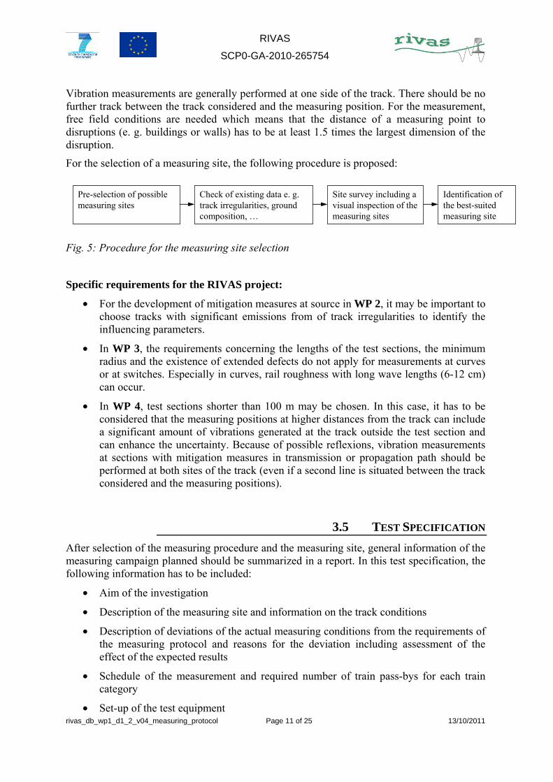
For the selection of a measuring site, the following procedure is proposed:
Fig. 5: Procedure for the measuring site selection
Specific requirements for the RIVAS project:
• For the development of mitigation measures at source in WP 2, it may be important to choose tracks with significant emissions from of track irregularities to identify the influencing parameters.
• In WP 3, the requirements concerning the lengths of the test sections, the minimum radius and the existence of extended defects do not apply for measurements at curves or at switches. Especially in curves, rail roughness with long wave lengths (6-12 cm) can occur.
• In WP 4, test sections shorter than 100 m may be chosen. In this case, it has to be considered that the measuring positions at higher distances from the track can include a significant amount of vibrations generated at the track outside the test section and can enhance the uncertainty. Because of possible reflexions, vibration measurements at sections with mitigation measures in transmission or propagation path should be performed at both sites of the track (even if a second line is situated between the track considered and the measuring positions).
3.5 TEST SPECIFICATION
After selection of the measuring procedure and the measuring site, general information of the measuring campaign planned should be summarized in a report. In this test specification, the following information has to be included:
• Aim of the investigation
• Description of the measuring site and information on the track conditions
• Description of deviations of the actual measuring conditions from the requirements of the measuring protocol and reasons for the deviation including assessment of the effect of the expected results
• Schedule of the measurement and required number of train pass-bys for each train category
• Set-up of the test equipment
Pre-selection of possible measuring sites
Check of existing data e. g. track irregularities, ground composition, …
Site survey including a visual inspection of the measuring sites
Identification of the best-suited measuring site
RIVAS
SCP0-GA-2010-265754
rivas_db_wp1_d1_2_v04_measuring_protocol Page 12 of 25 13/10/2011
• Quantities to be measured and data analysis
3.6 TEST EQUIPMENT
Vibration velocity sensors or vibration acceleration sensors can be used for the measurements. The sensors shall be coupled to the ground by rods with a length of at least 30 cm. On each rod, not more than one sensor can be used. For the installation of the rods, the top soil which may be too soft or cohesionless and which may include plants and roots has to be removed. Then the rod is driven (by pressing or hammering) completely into the ground and the sensor is installed on top of the rod. Before the measurement, it has to be checked that the installed rod in combination with the vibration sensor has no natural frequencies below 250 Hz (e. g. by excitation of the rod using a hammer). If also horizontal measurements are planned, the horizontal natural frequency has to be determined and documented, too. The test equipment has to fulfil the requirements of the German standard DIN 45669-1 / 2 (English version available) [11, 12].
3.7 VIBRATION MEASUREMENTS
Vibration measurements have to be performed in the frequency range from 4 to 250 Hz. For special cases – especially for measurement at tracks situated on very soft soils as could be found e. g. in Sweden – the lower limit should be reduced to 1 Hz.
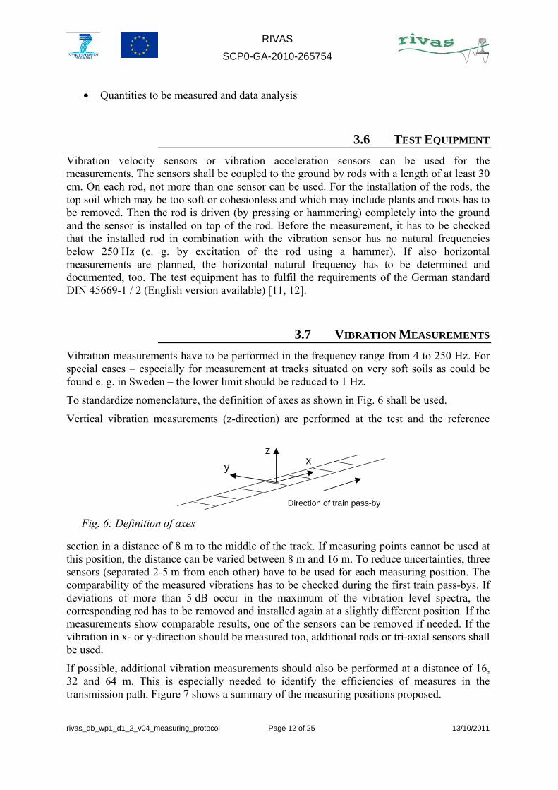
To standardize nomenclature, the definition of axes as shown in Fig. 6 shall be used.
Vertical vibration measurements (z-direction) are performed at the test and the reference
section in a distance of 8 m to the middle of the track. If measuring points cannot be used at this position, the distance can be varied between 8 m and 16 m. To reduce uncertainties, three sensors (separated 2-5 m from each other) have to be used for each measuring position. The comparability of the measured vibrations has to be checked during the first train pass-bys. If deviations of more than 5 dB occur in the maximum of the vibration level spectra, the corresponding rod has to be removed and installed again at a slightly different position. If the measurements show comparable results, one of the sensors can be removed if needed. If the vibration in x- or y-direction should be measured too, additional rods or tri-axial sensors shall be used.
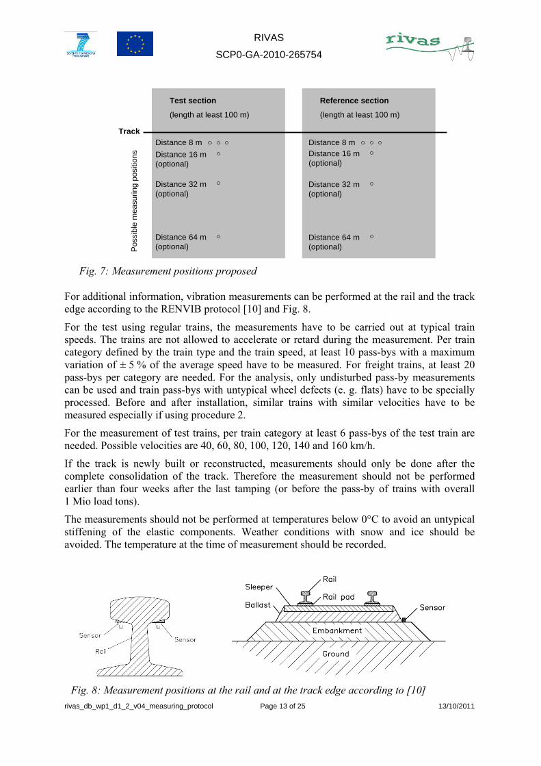
If possible, additional vibration measurements should also be performed at a distance of 16, 32 and 64 m. This is especially needed to identify the efficiencies of measures in the transmission path. Figure 7 shows a summary of the measuring positions proposed.
yx
z
Direction of train pass-by
Fig. 6: Definition of axes
RIVAS
SCP0-GA-2010-265754
rivas_db_wp1_d1_2_v04_measuring_protocol Page 13 of 25 13/10/2011
For additional information, vibration measurements can be performed at the rail and the track edge according to the RENVIB protocol [10] and Fig. 8.
For the test using regular trains, the measurements have to be carried out at typical train speeds. The trains are not allowed to accelerate or retard during the measurement. Per train category defined by the train type and the train speed, at least 10 pass-bys with a maximum variation of ± 5 % of the average speed have to be measured. For freight trains, at least 20 pass-bys per category are needed. For the analysis, only undisturbed pass-by measurements can be used and train pass-bys with untypical wheel defects (e. g. flats) have to be specially processed. Before and after installation, similar trains with similar velocities have to be measured especially if using procedure 2.
For the measurement of test trains, per train category at least 6 pass-bys of the test train are needed. Possible velocities are 40, 60, 80, 100, 120, 140 and 160 km/h.
If the track is newly built or reconstructed, measurements should only be done after the complete consolidation of the track. Therefore the measurement should not be performed earlier than four weeks after the last tamping (or before the pass-by of trains with overall 1 Mio load tons).
The measurements should not be performed at temperatures below 0°C to avoid an untypical stiffening of the elastic components. Weather conditions with snow and ice should be avoided. The temperature at the time of measurement should be recorded.
Test section
(length at least 100 m)
Reference section
(length at least 100 m)
Distance 8 m Distance 8 m
Distance 16 m (optional)
Distance 16 m (optional)
Distance 32 m (optional)
Distance 32 m (optional)
Distance 64 m (optional)
Distance 64 m (optional)
TrackP
ossi
ble
mea
suring
pos
ition
s
Fig. 7: Measurement positions proposed
Fig. 8: Measurement positions at the rail and at the track edge according to [10]

RIVAS
SCP0-GA-2010-265754
rivas_db_wp1_d1_2_v04_measuring_protocol Page 14 of 25 13/10/2011
Measurements of the background vibration levels are needed at each transducer.
3.8 VIBRATION DATA ANALYSIS
For the analysis of the measured data, the procedure as defined in the RENVIB protocol is used [10].
The analysis time Ta and the passage time Tp are determined corresponding to Fig. 9.
Then the third-octave spectra of the vibration velocity Lv(f) as described in RENVIB measuring protocol [10] is calculated for each train pass-by and each measuring position:
1. Filtering data from 4 to 250 Hz by using analogue or digital filter (specific cases: 1-250 Hz)
2. If needed, conversion from accelerations to velocities
3. Data sets are synchronized with regard to the time
4. Transformation of the velocity signal via FFT
5. Vibration level spectra are calculated by
6. The spectrum obtained is reduced to third-octave band spectra.
7. Building the sum level Lv
The vibration levels measured at sensors with the same distance from the track can be averaged arithmetically. Moreover, the vibration level spectra measured during the pass-by of trains belonging to the same train category are also averaged arithmetically.
dBT
TdB
ffL
p
av 10
010 log10
)(log20)( +=
νν
Fig. 9: Definition of passage time and analysis time: The analysis time Ta encloses the entire pass-by duration to get all the vibration energy. The passage time Tp corresponds to the pass-by time from buffer to buffer at a close reference point. If the pass-by time cannot be measured directly, the passage time can be determined from the measured data. By experience the passage time begins when the relative amplitude reaches about ¼ of the most frequently encountered maximum level and ends at the same level [9,10].
RIVAS
SCP0-GA-2010-265754
rivas_db_wp1_d1_2_v04_measuring_protocol Page 15 of 25 13/10/2011
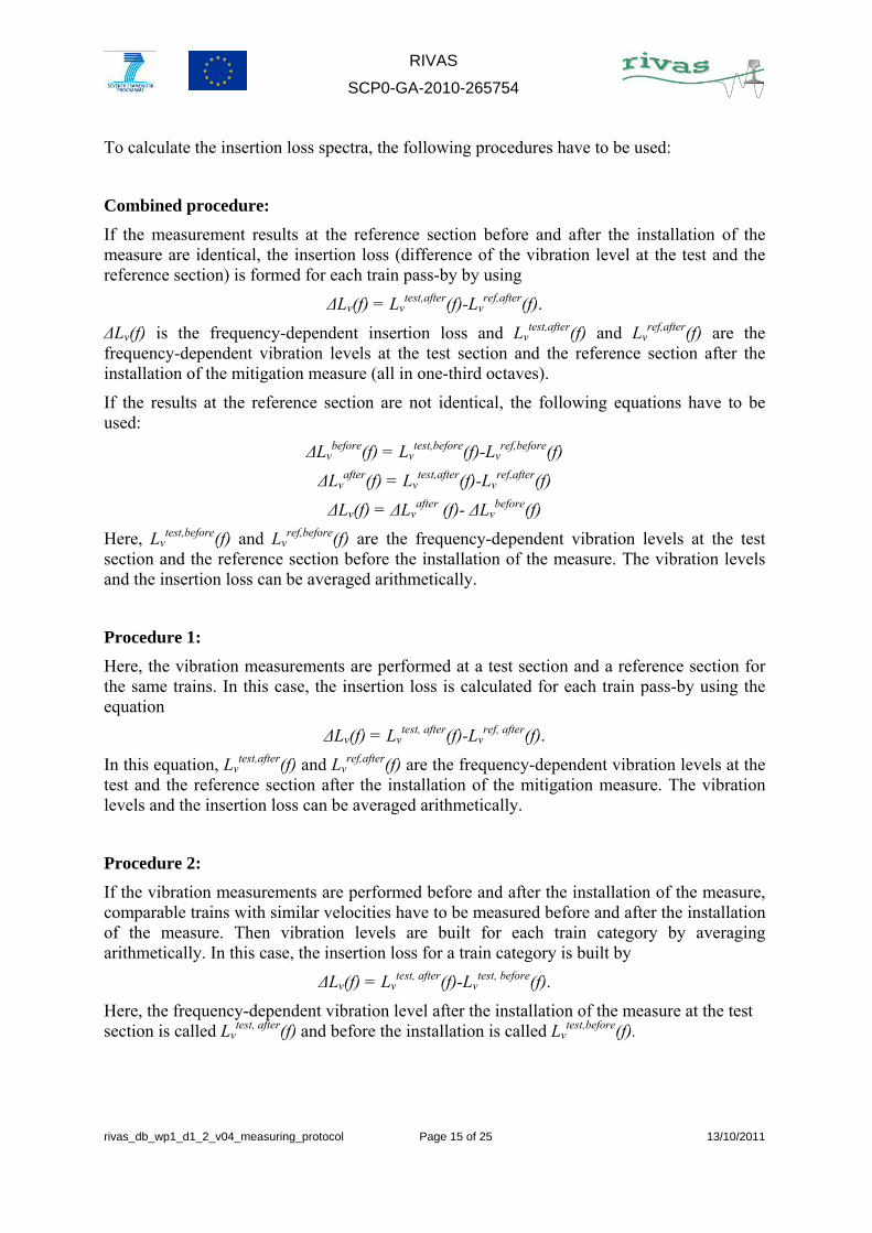
To calculate the insertion loss spectra, the following procedures have to be used:
Combined procedure:
If the measurement results at the reference section before and after the installation of the measure are identical, the insertion loss (difference of the vibration level at the test and the reference section) is formed for each train pass-by by using
ΔLv(f) = Lvtest,after(f)-Lv
ref,after(f).
ΔLv(f) is the frequency-dependent insertion loss and Lvtest,after(f) and Lv
ref,after(f) are the frequency-dependent vibration levels at the test section and the reference section after the installation of the mitigation measure (all in one-third octaves).
If the results at the reference section are not identical, the following equations have to be used:
ΔLvbefore(f) = Lv
test,before(f)-Lvref,before(f)
ΔLvafter(f) = Lv
test,after(f)-Lvref,after(f)
ΔLv(f) = ΔLvafter (f)- ΔLv
before(f)
Here, Lvtest,before(f) and Lv
ref,before(f) are the frequency-dependent vibration levels at the test section and the reference section before the installation of the measure. The vibration levels and the insertion loss can be averaged arithmetically.
Procedure 1:
Here, the vibration measurements are performed at a test section and a reference section for the same trains. In this case, the insertion loss is calculated for each train pass-by using the equation
ΔLv(f) = Lvtest, after(f)-Lv
ref, after(f).
In this equation, Lvtest,after(f) and Lv
ref,after(f) are the frequency-dependent vibration levels at the test and the reference section after the installation of the mitigation measure. The vibration levels and the insertion loss can be averaged arithmetically.
Procedure 2:
If the vibration measurements are performed before and after the installation of the measure, comparable trains with similar velocities have to be measured before and after the installation of the measure. Then vibration levels are built for each train category by averaging arithmetically. In this case, the insertion loss for a train category is built by
ΔLv(f) = Lvtest, after(f)-Lv
test, before(f).
Here, the frequency-dependent vibration level after the installation of the measure at the test section is called Lv
test, after(f) and before the installation is called Lvtest,before(f).
RIVAS
SCP0-GA-2010-265754
rivas_db_wp1_d1_2_v04_measuring_protocol Page 16 of 25 13/10/2011
3.9 FURTHER MEASUREMENTS
During the pass-by, the train speed has to be measured at the test and the reference section. Besides the train speed, information on the train type, the composition of the train, the train length and specifics (e. g. flats) have to be documented.
3.10 DOCUMENTATION
For each investigation, a measuring report has to be written including the following general aspects:
• Aim of the investigation
• Test date, test place, test personnel identification
• Measuring devices and the date of the latest calibration
• A general plan of the test site including the measuring positions
• Description of track and soil composition including all influencing parameters
• Description of measured trains including all influencing parameters
• Meteorological conditions (e. g. temperature, hydrometrics) during the investigation
• Time history of the investigation
• Information on background vibration
• Mathematical equations applied in the data analysis
• Reason for discarding measured data
The results of the complete vibration velocity measurements should be listed in tabular form. For each measured train pass-by and each sensor position, the following parameters are to be documented:
• Train category (train type and speed)
• Sum level Lv and third-octave spectrum at test and reference section before and after the installation of the measure
• Correction terms calculated from the measurements
• Insertion loss spectra in third-octave bands
For the graphical presentation, the third-octave spectra of the vibration levels have to be plotted for each train pass-by. Moreover, the spectra of the vibration levels averaged over the trains belonging to the same train category have to be plotted. For the insertion loss, the differences of the third-octave spectra of the vibration velocity level have to be plotted for both, single train pass-bys and averaged for each train category and speed.
The analyzed data and the raw data have to be stored together with all relevant information in the RIVAS database [3]. For the summary of parameters and results, the templates as shown in the attachment have to be used. The investigation belongs to the type “grade 1 measurement” as defined in the report [3] if only vibration and train speed has been
RIVAS
SCP0-GA-2010-265754
rivas_db_wp1_d1_2_v04_measuring_protocol Page 17 of 25 13/10/2011
measured. For investigations of the type “grade 2 to 5 measurements”, additional parameters concerning excitation, soil, track, train, and building have to be measured.
3.11 REFERENCE CONDITIONS
In the European countries involved in the RIVAS project, train, track and soil conditions are different. In order to compare the efficiencies of measures developed within the project and tested in different countries, reference conditions have to be defined and the measured data have to be transferred to these conditions at the end of the project. For the train, reference types are proposed by WP 5 (double stock trains and freight trains). Concerning reference soil conditions, different types are proposed in WP 4 [17]. For the track, the following reference conditions have to be used: rail UIC 60, soft rail pad (static stiffness of 60 MN/m), concrete sleeper (type B 70, 300 kg), 30 cm of ballast below the sleeper, sleeper distance 60 cm. Vibrations generated by corrugation and track irregularities are negligible. A procedure for the transfer of data from non-reference to reference conditions and vice versa will be developed within the frame of WP 1.2.
RIVAS
SCP0-GA-2010-265754
rivas_db_wp1_d1_2_v04_measuring_protocol Page 18 of 25 13/10/2011
4. REFERENCES
[1] Project RIVAS, Description of Work, 2010
[2] Project RIVAS, Del 1.1, Report with a description of test procedures for the determination of the dynamic soil characteristics, to be published in September 2011
[3] Project RIVAS; Del. 1.3, Description of the database structure of ground and vibration measurements, to be published in September 2011
[4] G. Müller, M. Möser, Taschenbuch der Technischen Akustik, Springer, 2004
[5] F.H.Müller-Borruttau, Elastic elements reduce the loads expected on the permanent way, http://www.imb-dynamik.de/pdf/publ/
[6] C. Madshus, Measurement ground-borne noise and vibration arising from rail systems, Measurement of dynamic properties of the ground, internal technical report for ISO-working-group ISO 14837, 2010
[7] ISO 14837-1 “Mechanical vibration - Ground-borne noise and vibration arising from rail systems - Part 1: General guidance”, 2005
[8] DIN 45672-1 "Vibration measurement associated with railway traffic systems - Part 1: Measuring method", 2009
[9] DIN 45672-1 "Vibration measurement associated with railway traffic systems - Part 2: Assessment method”, 1995
[10] RENVIB II Phase 3, Measurement protocol vibration and ground borne noise, AEAT, 2003
[11] DIN 45669-1 "Measurement of vibration immission - Part 1: Vibration meters - Requirements and tests", 2010
[12] DIN 45669-2 "Measurement of vibration immission - Part 2: Measuring method", 2005
[13] Federal Transit Administration, Transit Noise and Vibration Impact Assessment, 2006
[14] D. Thompson, Railway Noise and Vibration, Elsevier, 2009
[15] BS 6472-1:2008, Guide to evaluation of human exposure to vibration in buildings. Vibration sources other than blasting, 2008
[16] Royal Decree 1367/2007, Spain, 2007
[17] Project RIVAS, Del. 4.1, Scope of the parametric study on mitigation measures on the transmission path, to be published in September 2011
RIVAS
SCP0-GA-2010-265754
rivas_db_wp1_d1_2_v04_measuring_protocol Page 19 of 25 13/10/2011
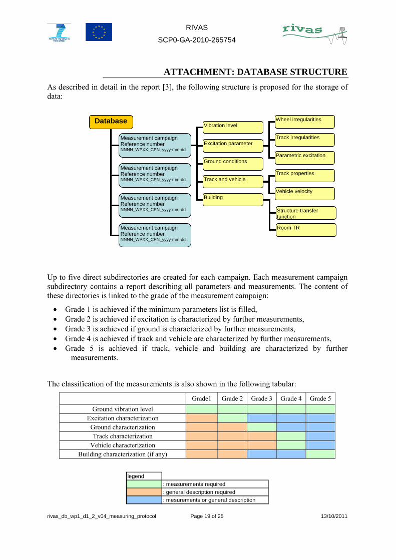
ATTACHMENT: DATABASE STRUCTURE
As described in detail in the report [3], the following structure is proposed for the storage of data:
Up to five direct subdirectories are created for each campaign. Each measurement campaign subdirectory contains a report describing all parameters and measurements. The content of these directories is linked to the grade of the measurement campaign:
• Grade 1 is achieved if the minimum parameters list is filled, • Grade 2 is achieved if excitation is characterized by further measurements, • Grade 3 is achieved if ground is characterized by further measurements, • Grade 4 is achieved if track and vehicle are characterized by further measurements, • Grade 5 is achieved if track, vehicle and building are characterized by further
measurements.
The classification of the measurements is also shown in the following tabular:
Grade1 Grade 2 Grade 3 Grade 4 Grade 5
Ground vibration level Excitation characterization
Ground characterization Track characterization
Vehicle characterization Building characterization (if any)
legend
: measurements required
: general description required
: mesurements or general description
Database
Measurement campaign Reference number NNNN_WPXX_CPN_yyyy-mm-dd
Vibration level
Excitation parameter
Wheel irregularities
Track irregularities
Parametric excitation Ground conditions
Track and vehicle
Building
Track properties
Vehicle velocity
Structure transfer function
Room TR
Measurement campaign Reference number NNNN_WPXX_CPN_yyyy-mm-dd
Measurement campaign Reference number NNNN_WPXX_CPN_yyyy-mm-dd
Measurement campaign Reference number NNNN_WPXX_CPN_yyyy-mm-dd
RIVAS
SCP0-GA-2010-265754
rivas_db_wp1_d1_2_v04_measuring_protocol Page 20 of 25 13/10/2011
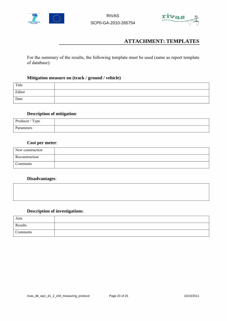
ATTACHMENT: TEMPLATES
For the summary of the results, the following template must be used (same as report template of database):
Mitigation measure on (track / ground / vehicle)
Title
Editor
Date
Description of mitigation:
Producer / Type
Parameters
Cost per meter:
New construction
Reconstruction
Comments
Disadvantages:
Description of investigations:
Aim
Results
Comments

RIVAS
SCP0-GA-2010-265754
rivas_db_wp1_d1_2_v04_measuring_protocol Page 21 of 25 13/10/2011
Site description:
Country
Weather conditions
Pictures / drawings:
Site
Mitigation measure
Measurement Parameters:
Measuring points
Position
Number of sensors
Sensors Type
Ground Coupling
Directions
Software Name
Version
Exitation description:
Train
Type
Velocity
Wheel roughness quality
Rail roughness quality
Track irregularities
(freight / passenger / IC / HST …)
(new / old wheels)
(corrugation / no corrugation)
(joints, switch …)
Excitation
Other Source Type
Parameters
RIVAS
SCP0-GA-2010-265754
rivas_db_wp1_d1_2_v04_measuring_protocol Page 22 of 25 13/10/2011
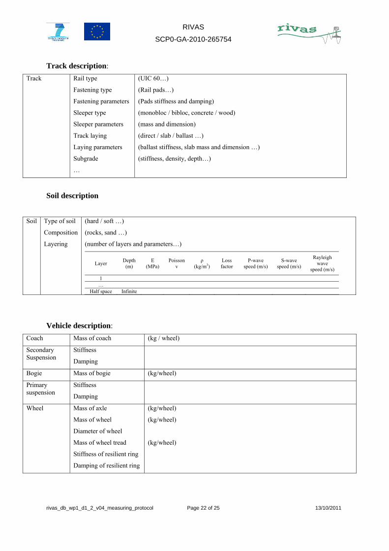
Track description:
Track Rail type
Fastening type
Fastening parameters
Sleeper type
Sleeper parameters
Track laying
Laying parameters
Subgrade
…
(UIC 60…)
(Rail pads…)
(Pads stiffness and damping)
(monobloc / bibloc, concrete / wood)
(mass and dimension)
(direct / slab / ballast …)
(ballast stiffness, slab mass and dimension …)
(stiffness, density, depth…)
Soil description
Soil Type of soil
Composition
Layering
(hard / soft …)
(rocks, sand …)
(number of layers and parameters…)
Layer Depth
(m) E
(MPa) Poisson
v ρ
(kg/m3) Loss factor
P-wave speed (m/s)
S-wave speed (m/s)
Rayleigh wave
speed (m/s)
1 …
Half space Infinite
Vehicle description:
Coach Mass of coach (kg / wheel)
Secondary Suspension
Stiffness
Damping
Bogie Mass of bogie (kg/wheel)
Primary suspension
Stiffness
Damping
Wheel Mass of axle
Mass of wheel
Diameter of wheel
Mass of wheel tread
Stiffness of resilient ring
Damping of resilient ring
(kg/wheel)
(kg/wheel)
(kg/wheel)
RIVAS
SCP0-GA-2010-265754
rivas_db_wp1_d1_2_v04_measuring_protocol Page 23 of 25 13/10/2011
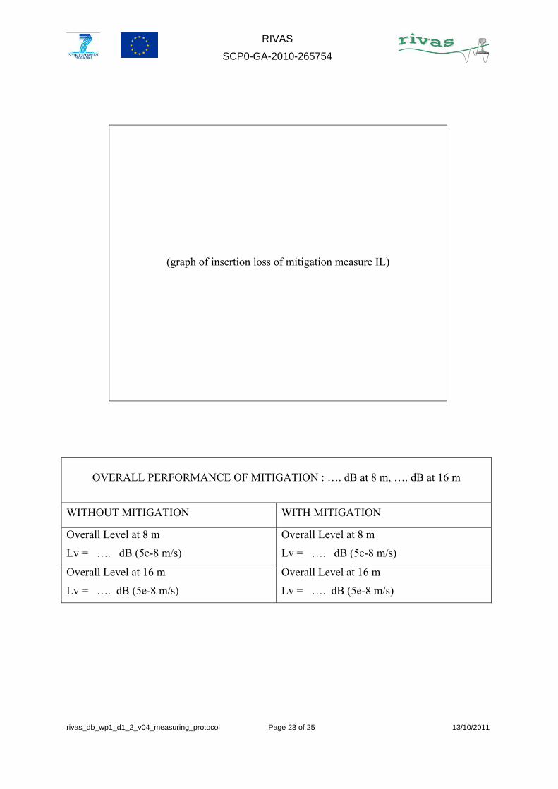
(graph of insertion loss of mitigation measure IL)
OVERALL PERFORMANCE OF MITIGATION : …. dB at 8 m, …. dB at 16 m
WITHOUT MITIGATION WITH MITIGATION
Overall Level at 8 m
Lv = …. dB (5e-8 m/s)
Overall Level at 8 m
Lv = …. dB (5e-8 m/s)
Overall Level at 16 m
Lv = …. dB (5e-8 m/s)
Overall Level at 16 m
Lv = …. dB (5e-8 m/s)
RIVAS
SCP0-GA-2010-265754
rivas_db_wp1_d1_2_v04_measuring_protocol Page 24 of 25 13/10/2011
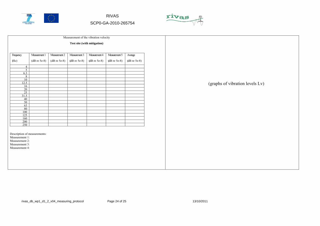
Measurement of the vibration velocity
Test site (with mitigation)
Frequency
(Hz)
Measurement 1
(dB re 5e-8)
Measurement 2
(dB re 5e-8)
Measurement 3
(dB re 5e-8)
Measurement 4
(dB re 5e-8)
Measurement 5
(dB re 5e-8)
Average
(dB re 5e-8)
4 5
6.3 8
10 12.5
16 20 25
31.5 40 50 63 80
100 125 160 200 250
Description of measurements: Measurement 1: Measurement 2: Measurement 3: Measurement 4:
(graphs of vibration levels Lv)
RIVAS
SCP0-GA-2010-265754
rivas_db_wp1_d1_2_v04_measuring_protocol Page 25 of 25 13/10/2011
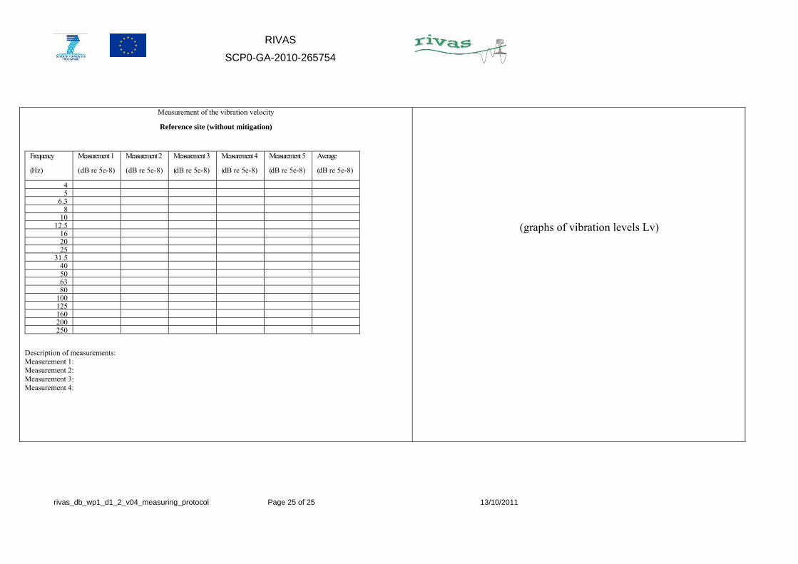
Measurement of the vibration velocity
Reference site (without mitigation)
Frequency
(Hz)
Measurement 1
(dB re 5e-8)
Measurement 2
(dB re 5e-8)
Measurement 3
(dB re 5e-8)
Measurement 4
(dB re 5e-8)
Measurement 5
(dB re 5e-8)
Average
(dB re 5e-8)
4 5
6.3 8
10 12.5
16 20 25
31.5 40 50 63 80
100 125 160 200 250
Description of measurements: Measurement 1: Measurement 2: Measurement 3: Measurement 4:
(graphs of vibration levels Lv)
Recommended