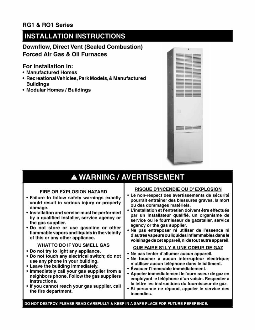
RG1 & RO1 Series
Downflow, Direct Vent (Sealed Combustion)Forced Air Gas & Oil Furnaces
For installation in:•ManufacturedHomes•RecreationalVehicles,ParkModels,&Manufactured
Buildings•ModularHomes/Buildings
InStAllAtIOn InStRuCtIOnS
WARNING/AVERTISSEMENT
FIREOREXPLOSIONHAZARD•Failure to follow safety warnings exactly
couldresult inseriousinjuryorpropertydamage.
• Installationandservicemustbeperformedbyaqualifiedinstaller,serviceagencyorthegassupplier.
•Do not store or use gasoline or otherflammablevaporsandliquidsinthevicinityofthisoranyotherappliance.
WHATTODOIFYOUSMELLGAS•Donottrytolightanyappliance.•Donottouchanyelectricalswitch;donot
useanyphoneinyourbuilding.•Leavethebuildingimmediately.• Immediatelycallyourgassupplierfroma
neighborsphone.Followthegassuppliersinstructions.
• Ifyoucannotreachyourgassupplier,callthefiredepartment.
RISQUED’INCENDIEOUD’EXPLOSION•Lenon-respectdesavertissementsdesécurité
pourraitentraînerdesblessuresgraves,lamortoudesdommagesmatériels.
•L’installationetl’entretiendoiventêtreeffectuéspar un installateur qualifié, un organisme deserviceoulefournisseurdegazstaller,serviceagencyorthegassupplier.
•Ne pas entreposer ni utiliser de l’essence nid’autresvapeursouliquidesinflammablesdanslevoisinagedecetappareil,nidetoutautreappareil.
QUEFAIRES’ILYAUNEODEURDEGAZ•Nepastenterd’allumeraucunappareil.•Ne toucher à aucun interrupteur électrique;
n’utiliseraucuntéléphonedanslebâtiment.•Évacuerl’immeubleimmédiatement.•Appelerimmédiatementlefournisseurdegazen
employantletéléphoned’unvoisin.Respecteràlalettrelesinstructionsdufournisseurdegaz.
•Sipersonnenerépond,appeler leservicedesincendies.
DONOTDESTROY.PLEASEREADCAREFULLY&KEEPINASAFEPLACEFORFUTUREREFERENCE.
2
TABLEOFCONTENTSIMPORTANTSAFETYINFORMATION ..................... 3
REQUIREMENTS&CODES ..................................... 3
GENERALINFORMATION ........................................ 5Manufacturer Warranty ............................................ 5Minimum Clearances ............................................... 5Applications ............................................................. 5Unit Location ............................................................ 5
CIRCULATINGAIRREQUIREMENTS ...................... 7Return Air Connections ............................................ 7Supply Air Connections ........................................... 7
FURNACEINSTALLATION ....................................... 8General Information ................................................. 8Locating & Cutting Duct Openings ........................... 8Standard Duct Connector Installation ...................... 8
Alternate Attachment Method ................................ 9Round Duct Connector Installation .......................... 10Installing the Furnace .............................................. 10
ROOFJACKINSTALLATION ................................... 11Roof Jack Selection ................................................. 11Locating & Cutting Roof/Ceiling Openings .............. 12Installing The Roof Jack .......................................... 12Installation of Transit-Mode Venting System ........... 13
ELECTRICALINFORMATION .................................. 14Line Voltage Wiring .................................................. 14
Connecting Power Supply Wires ........................... 14Low Voltage Wiring .................................................. 15
Connecting Thermostat Wires ............................... 15Verifying Anticipator Setting .................................. 15
Grounding ................................................................ 15
FUELSUPPLY&PIPING .......................................... 16Leak Check .............................................................. 17Oil Tank & Piping Installation ................................... 17
One-Line System .................................................. 18Two-Line System................................................... 18
Fuel line Hook-Up .................................................... 18Fuel Line Bleeding ................................................... 18
Priming furnaces equipped with Honeywell........... 19R7184 primary control: .......................................... 19Priming furnaces equipped with Beckett 7505primary control....................................................... 19
Fuel Oil Type ........................................................... 19Conversion to Propane (LP) Gas ............................. 19
Atmospheric & Direct Ignition Furnaces ................ 19High Altitude Conversion ......................................... 19Flue Gas Sampling .................................................. 20
STARTUP&ADJUSTMENTS ................................... 21RG1 Operating Instructions ..................................... 22
How to Shut Off Gas - Direct Ignition .................... 22RO1 Operating Instructions ..................................... 22
How to Shut Off Gas - Oil & Gas Gun ................... 22Verifying & Adjusting Temperature Rise .................. 23Burner Adjustments ................................................. 23
Gas Pressure ........................................................ 23Combustion Air ........................................................ 23
Oil Gun Only (RO1 Models) .................................. 23Electrode Setting (Oil Gun Only) ............................. 23Switching Ignition Control between Interruptedand Intermittent Duty ............................................... 23
OPERATINGSEQUENCE ......................................... 24Direct Ignition Furnaces (RG1 Models).................... 24Oil Gun Furnaces (RO1 Models) ............................. 24
FURNACECONTROLS&FUNCTIONS ................... 24
TROUBLESHOOTING ............................................... 25Direct Ignition Furnaces (RG1 Models).................... 25Oil Gun - Honeywell R7184 or Beckett 7505Controls Only - RO1 Series. .................................... 26
OPTIONALACCESSORIES ...................................... 27Optional Add-On Air Conditioning ............................ 28
MAINTENANCE ......................................................... 28Homeowner Information .......................................... 28Installer Information ................................................. 28Additional Oil Furnace Maintenance ........................ 28
FIGURES&TABLES ................................................. 29Table 10. RG1/RO1 Furnace Specifications -
Factory Settings .................................... 29Table 11. Equivalent Orifice Sizes for High
Altitude Installations .............................. 30Table 12. A/C Blower Speed Selection Chart ....... 30
Gas Information ....................................................... 31Table 13. Gas Flow Rates ..................................... 31Table 14. Gas Pipe Capacities .............................. 31
Electrical Information ............................................... 32Figure 38. Gas Direct Ignition Furnace, Heating
& A/C Ready - All RG1 Models ............ 32Figure 39. Gas and Oil Furnaces, A/C Ready -
RO1 (066, 086) Models ....................... 33
INSTALLATION/PERFORMANCECHECKLIST ... 36
3
IMPORTANTSAFETYINFORMATIONSafety markings are used frequently throughout this manual to designate a degree or level of seriousness and should not be ignored. WARnInG indicates a potentially hazardous situation that if not avoided, could result in personal injury or death. CAutIOn indicates a potentially hazardous situation that if not avoided, may result in minor or moderate injury or property damage.
WARnInG:The safety information listed below must befollowed during the installation, service, andoperationofthisfurnace.Failuretofollowsafetyrecommendations could result in possibledamage to the equipment, serious personalinjuryordeath.
WARnInG:FIREANDEXPLOSIONHAZARD
Canresultinseriousinjuryordeath.
Donotstoreorusegasolineorotherflammablevaporsandliquidsinthevicinityofthisoranyotherappliance.Storageoforuseofgasolineorotherflammablevaporsorliquidsinthevicinityof this or any appliance can result in seriousinjuryordeath.
AVERTISSEMENT:RISQUED’INCENDIEETD’EXPLOSION
Risquedeblessuresgravesoudemort.
Ne pas entreposer ni utiliser de l’essence nid’autres vapeurs ou liquides inflammablesdans le voisinage de cet appareil, ni de toutautreappareil.Lefaitd’entreposeroud’utiliserde l’essence ou d’autres liquides ou vapeursinflammablesàproximitédecetappareiloudetoutautreappareilpeutcauserdesblessuresgravesoulamort.
WARnInG:Donotusethisapplianceifanyparthasbeensubmerged under water. Immediately call aqualified service technician to inspect theapplianceandtoreplaceanypartofthecontrolsystem and any gas control that has beensubmerged underwater.
REQUIREMENTS&CODES• This furnace must be installed in accordance with
these instructions, all applicable local building codes and the current revision of the National Fuel Gas Code (NFPA54/ANSI Z223.1) or the Natural Gas and Propane Installation Code, CAN/CGA B149.1.
• CEgénérateurd’airchauddoitêtreinstalléconformémentaux instructions du fabricant et aux codes locaux. En l’absence de code local, respecter la norme ANSIZ223.,1,instituléNationalFuelGasCodeoulescodesd’installationCAN/GCA-B149.
• Useonlywith typeofgasapproved for this furnace.Refer to the furnace rating plate.
• Install this furnace in accordance to the minimumclearances to combustible materials listed in Table 1, (page 6).
• Provideadequatecombustionandventilationairtothefurnace space as specified on page 7 and page 23. Do not block or obstruct air openings on the furnace, air openings to the area where the furnace is installed, or the space around the furnace.
• Combustion products must be discharged outdoors.Connect this furnace to an approved vent system, as specified on pages 11 - 13.
• Never test for gas leaks with an open flame. Use acommercially available soap solution to check all connections. See page 17.
• Thisfurnaceisdesignedtooperatewithamaximumexternal pressure rise of 0.5 inches of water column. Consult Table 12, (page 30) and the rating plate for thepropercirculatingairflowandtemperaturerise.
NOTE: It is important that the duct system be designed tohandlethedesiredflowrateandexternalpressurerise. An improperly designed duct system can result in nuisance shutdowns, and comfort or noise issues.
• Whensupplyductscarryaircirculatedbythefurnaceto areas outside the space containing the furnace, the return air shall also be handled by duct(s) sealed to the furnace casing and terminating outside the space containing the furnace. See pages 8 - 10.
• Thisfurnacemaynotbeusedfortemporaryheatingofbuildings or structures under construction.
• Theinformationlistedbelowisforreferencepurposesonly and does not necessarily have jurisdiction over local or state codes. Always consult with local authorities before installing any gas appliance.

4
Additional information listed below is for reference purposes only and does not necessarily have jurisdiction over local or state codes. Always consult with local authorities before installing any gas appliance.
Combustion & Ventilation Air• US:NationalFuelGasCode(NFGC),AirforCombustionand
Ventilation• CANADA: Natural Gas and Propane Installation Codes
(NSCNGPIC), Venting Systems and Air Supply for Appliances
DuctSystems• USandCANADA:AirConditioningContractorsAssociation
(ACCA) Manual D, Sheet Metal and Air Conditioning Contractors National Association (SMACNA), or American Society of Heating, Refrigeration, and Air Conditioning Engineers (ASHRAE) Fundamentals Handbook
ElectricalConnections• US:NationalElectricalCode(NEC)ANSI/NFPA70• CANADA:CanadianElectricalCodeCSAC22.1
GasPiping&GasPipePressureTesting• US:NFGCandNationalPlumbingCodes• CANADA:NSCNGPIC
General Installation• US:Currenteditionof theNFGCand theNFPA90B.For
copies, contact the National Fire Protection Association Inc., Batterymarch Park, Quincy, MA 02269; or American Gas Association, 400 N. Capitol, N.W., Washington DC 20001 or www.NFPA.org
• CANADA:NSCNGPIC.Foracopy,contactStandardSales,CSA International, 178 Rexdale Boulevard, Etobicoke (Toronto), Ontario, M9W 1R3 Canada
Safety• US:(NFGC)NFPA54–1999/ANSIZ223.1andtheInstallation
Standards, Warm Air Heating and Air Conditioning Systems ANSI/NFPA 90B.
• FederalManufacturedHomeConstructions&SafetyStandard(H.U.D. Title 24, Part 3280.707[a][2])
• The Standard for Manufactured Home Installations(Manufactured Home Sites, Communities, and Set-Ups) ANSI A225.1 and/or CAN/CSA-2240 MH Series).
• American National Standard (ANSI-119.2/NFPA-501C) forall recreational vehicle installations.
• CANADA:CAN/CGA-B149.1and.2–M00NationalStandardof Canada. (NSCNGPIC)
• The Commonwealth of Massachusetts requirescompliance with regulation 248 CMR 4.00 and 5.00 for installationofthrough–the–wallventedgasappliancesas follows:
1. For direct-vent appliances, mechanical-vent heating appliances or domestic hot water equipment, where the bottom of the vent terminal and the air intake is installed below four feet above grade the following requirements must be satisfied:a.) A carbon monoxide (CO) detector and alarm shall be
placedoneachfloorlevelwheretherearebedrooms.The detector shall comply with NFPA 720 (2005 Edition) and be mounted in the living area outside the bedroom(s).
b.) A (CO) detector shall be located in the room that houses the appliance or equipment and shall:•Bepoweredbythesameelectricalcircuitasthe
appliance or equipment. Only one service switch shall power the appliance and the (CO) detector;
•Havebatteryback-uppower;•MeetANSI/UL2034Standardsandcomplywith
NFPA 720 (2005 Edition); and Approved and listed by a Nationally Recognized Testing Laboratory as recognized under 527 CMR.
c.) A Product-approved vent terminal must be used, and if applicable, a product-approved air intake must be used. Installation shall be in strict compliance with the manufacturer’sinstructions.Acopyoftheinstallationinstructions shall remain with the appliance or equipment at the completion of the installation.
d.) A metal or plastic identification plate shall be mounted at the exterior of the building, 4 feet directly above the location of vent terminal. The plate shall be of sufficient size, easily read from a distance of eight feet away, and read “Gas Vent Directly Below”.
2. For direct-vent appliances, mechanical vent heating appliances or domestic hot water equipment where the bottom of the vent terminal and the air intake is installed above four feet above grade the following requirements must be satisfied:a.) A (CO) detector and alarm shall be placed on each
floorlevelwheretherearebedrooms.Thedetectorshall comply with NFPA 720 (2005 Edition) and be mounted in the living area outside the bedroom(s).
b.) The (CO) detector shall:•Belocatedintheroomthathousestheapplianceor
equipment;•Behard-wired,batterypoweredorboth.•ShallcomplywithNFPA720(2005Edition).
c.) A product-approved vent terminal must be used, and if applicable, a product-approved air intake must be used. Installation shall be in strict compliance with the manufacturer’sinstructions.Acopyoftheinstallationinstructions shall remain with the appliance or equipment at the completion of the installation.
5
GENERALINFORMATION
CAutIOn:• DoNotalterormodifythisfurnaceoranyof
itscomponents.•Neverattempttorepairdamagedorinoperable
components.Thismaycauseunsafeoperation,explosion,fireand/orasphyxiation.
•If furnace malfunctions or does not operateproperly, contact a qualified service agencyorgasutilityforassistance.
ManufacturerWarranty(Owner’sResponsibilities)A warranty certificate with full details is included with these instructions. Carefully review these responsibilities with your manufactured housing dealer, service company or gas supplier. It is the sole responsibility of the homeowner to make certain the gas furnace has been correctly set up and converted to the proper fuel (L.P. gas or Natural gas) and adjusted to operate properly. All gas furnaces are manufactured for Natural gas and must be field converted when using L.P. gas.
The manufacturer will not be responsible for any costs found necessary to correct problems due to improper setup, improper installation, furnace adjustments, improper operating procedure on the part of the user, etc. Some specific examples of service calls which cannot be included in warranty payments are:
• Convertingthefurnacetouseanothertypeofgas.• Repairingductworkinthehomefoundtobefaulty.• Correcting wiring problems in the electrical circuit
supplying the furnace.• Resettingcircuitbreakers,blownfusesorotherswitches.• Correcting problems due to improper gas supply
pressure to the furnace.• Providing instructional training on how to light and
operate the furnace.• Furnace problems caused by installation of an air
conditioner, heat pump or other air comfort devices.• AddingaRoofJackextensionbecauseofunusualwind
and/or snow conditions.• Revisinginstallationofthefurnaceflueassembly(Roof
Jack).• Adjustingorcalibratingofthermostat.• Anyconstructiondebriswhichfallsintofluesystem.
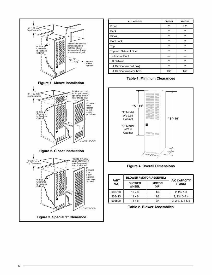
MinimumClearancesThis heating appliance must be installed with clearances not less than the minimums listed in Table 1, (page 6). This furnace must be installed with ample clearance for easy access to the air filter, blower assembly, burner assembly, controls, and vent connections. See Figure 1, Figure 2, and Figure 3 (page 6).
• Thedimensionsoftheroomoralcovemustbeabletoaccommodate the overall size of the furnace and the installation clearances listed in Table 1 and in Figure 4 (page 6).
• Alcove installations: minimum 18” clearance at frontof furnace shall be provided for future servicing. A removable access panel should be installed between top of the furnace door frame and the ceiling.
• Closet installationsmustusea louvereddoorhavinga minimum free area of 235 in2 when located 6” from furnace or 390 in2 for 5 ton ready RG1/RO1 furnaces. For special clearance between 1” - 6”, requirements are a louvered door with a minimum of 250 in2 free area, with the openings in the closet door in line with the louvered openings in the furnace door. A fully louvered closet door may be used. See Circulating Air Requirements on page 7.
• Thefurnacemustbekeptfreeandclearofinsulatingmaterial. Examine the furnace area when the furnace is installed or when insulation is added. Insulating material may be combustible.
ApplicationsRG1 Series gas and RO1 Series oil furnaces are listed direct vent (sealed combustion), downflow heatingappliances for manufactured (mobile) homes, recreational vehicles, and for use in residential/modular/commercial construction. The furnace must be located so that venting can be properly achieved.
Air conditioning may be added to structures with RG1/RO1 series furnaces using air conditioning or conventional units. This Installation Instruction manual includes special requirements for incorporation of air conditioning equipment to the RG1/RO1 series of furnaces. See Table 12, (page 30).
Multi-speed blower assemblies shown in Table 2, (page 6), have been certified for field installation in RG1/RO1 Series furnaces.
unit location• Thefurnaceshallbeappropriatelylocatedtothesupply
and return air distribution system (page 7). Sides and back of the furnace may be enclosed by wall framing. See Minimum Clearances and Figure 1, Figure 2, and Figure 3 (page 6).
• Thefurnaceinstallationisonlyintendedforfreeairreturnthrough the furnace door louvers. DO NOT connect a ducted return air system directly to the furnace. Improper installation may create a hazard and damage equipment, as well as void all warranties.
• Furnacemaybeinstalledoncombustibleflooringwhenusing manufacturer approved duct connectors. See pages 8-10.
• Wheninstalledinaresidentialgarage,thefurnacemustbe positioned so the burners and the source of the ignition are located no less than 18 inches above the floorandprotectedfromphysicaldamagebyvehicles.
6
Figure 3. Special1”Clearance
Removable access panel should be installed abovefurnace door frame to access roof jack
NearestWall orPartition
18"(457 mm)
6" (152 mm)Top Clearance
0" SideClearanceto FurnaceCabinet
6" (152 mm)Top Clearance
0" SideClearanceto FurnaceCabinet
Provide min. 235sq. in. (1516 cm )open free area infront or side wall
2
orIn closetdoorlocatedat top,centeror bottom
CLOSET DOOR
6" (152 mm)Top Clearance
Provide min. 250sq. in. (1613 cm )open free area infront or side wall
2
a fullylouvereddoor maybe used
CLOSET DOOR
6"(152 mm)
1"(25 mm)
0" SideClearanceto FurnaceCabinet
orin closetdoor
Figure 2. Closet Installation
Figure 1. AlcoveInstallation
“A”- 56"
23 3/4"
“B”- 76"
“A” Model w/o Coil Cabinet
“B” Model w/Coil Cabinet
19 3/4”
Figure 4. OverallDimensions
Table 1
table 1. MinimumClearances
ALLMODELS CLOSET ALCOVE
Front 6” 18”
Back 0” 0”
Sides 0” 0”
Roof Jack 0” 0”
Top 6” 6”
Top and Sides of Duct 0” 0”
Bottom of Duct — —
B Cabinet 0” 0”
A Cabinet (w/ coil box) 0” 0”
A Cabinet (w/o coil box) 1/4” 1/4”
Table 2
table 2. Blower Assemblies
PARTnO.
BLOWER/MOTORASSEMBLYA/CCAPACITY
(tOnS)BLOWERWHEEL
MOTOR(HP)
903773 10 x 8 1/4 2, 2½ & 3
903413 11 x 8 1/2 2, 2½, 3 & 4
903890 11 x 8 3/4 2, 2½, 3, 4 & 5
7
CIRCULATINGAIRREQUIREMENTS
WARnInG:Donotallowcombustionproductstoenterthecirculating air supply. Failure to prevent thecirculation of combustion products into theliving space can create potentially hazardousconditionsincludingcarbonmonoxidepoisoningthatcouldresultinpersonalinjuryordeath.
All return ductwork must be secured to thefurnacewithsheetmetalscrews.Forinstallationsinconfinedspaces,allreturnductworkmustbeadequatelysealed.Thejointbetweenthefurnaceandthereturnairplenummustbeairtight.
Thesurfacethatthefurnaceismountedonmustprovidesoundphysicalsupportofthefurnacewith no gaps, cracks or sagging between thefurnaceandthefloororplatform.
Return air and circulating air ductwork mustnotbeconnectedtoanyotherheatproducingdevicesuchasafireplaceinsert,stove,etc.Thismayresultinfire,explosion,carbonmonoxidepoisoning,personalinjury,orpropertydamage.
Return Air ConnectionsU.S.A. home manufacturers shall comply with all of the following conditions to have acceptable return air systems for closet installed forced air heating appliances:
• Thereturnairopeningintotheclosetshallnotbelessthanspecifiedintheappliance’slisting.
• The cross-sectional area of the return duct systemleading into the closet, when located in the floor orceiling shall not be less than 235 in2 (or 390 in2 for 5 ton ready RG1/RO1 Furnaces).
CAutIOn:HAZARDOFASPHYXIATION:Donotcoverorrestrictreturnairopening.
• Meansshallbeprovidedthatpreventinadvertentclosureofflatobjectsplacedoverthereturnairopeninglocatedinthefloorofthecloset(versustheverticalfrontorsidewall).
• Thetotalfreeareaofopeningsinthefloororceilingregisters serving the return air duct system must be at least 235 in2. At least one register should be located where it is not likely to be covered by carpeting, boxes and other objects.
• Materialslocatedinthereturnductsystemmusthaveaflamespreadclassificationof200orless.Thisincludesa closet door if the furnace is in a closet.
• Noncombustiblepanshaving1”upturnedflangesarelocatedbeneathopeningsinafloorductsystem.
• Wiringmaterialslocatedinthereturnductsystemshallconform to Articles 300-22 of the National Electrical Code (ANSI C1/NFPA-70).
• Gaspipingisnotruninorthroughthereturnductsystem.
CAutIOn:HAZARDOFASPHYXIATION:Negativepressureinside thecloset,withclosetdoorclosedandthe furnace blower operating on high speed,shallbenomorenegativethanminus0.05inchwater column.
• Test thenegativepressure in theclosetwith theair-circulating fan operating at high speed and the closet closed. The negative pressure is to be no more negative than minus 0.05 inch water column.
• Airconditioningsystemsmayrequiremoreductregisterandopenlouverareatoobtainnecessaryairflow.
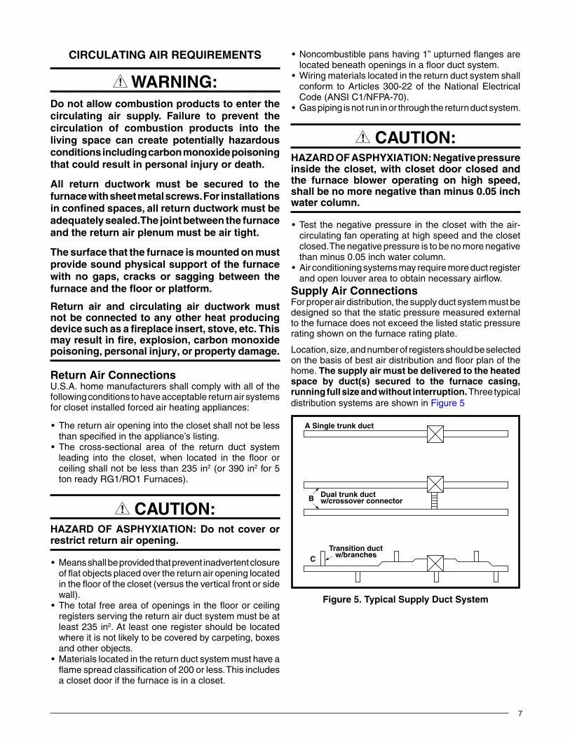
SupplyAirConnectionsFor proper air distribution, the supply duct system must be designed so that the static pressure measured external to the furnace does not exceed the listed static pressure rating shown on the furnace rating plate.
Location, size, and number of registers should be selected onthebasisofbestairdistributionandfloorplanofthehome. Thesupplyairmustbedeliveredtotheheatedspace by duct(s) secured to the furnace casing,runningfullsizeandwithoutinterruption. Three typical distribution systems are shown in Figure 5
Figure 5. TypicalSupplyDuctSystem
A Single trunk duct
B Dual trunk ductw/crossover connector
CTransition duct w/branches
8
FURNACEINSTALLATIONNOTE:These Installation procedures are suggested for typical furnace installations. Since each installation is different, the sequence of instructions may differ from the actual installation. Only qualified HVAC technicians should install this furnace.
The installer must be familiar with and comply with all codes and regulations applicable to the installation of these heating appliances and related equipment. In the absence of local codes, the installation must be in accordance with the current provisions of one or more of the following standards.
• FederalManufacturedHomeConstructions&SafetyStandard (H.U.D. Title 24, Part 3280.707[a][2])
• AmericanNationalStandard(ANSI-119.2/NFPA-501C)for all recreational vehicle installations.
• AmericanNationalStandard(ANSI-Z223.1/NFPA-54)and/or CAN/CSA B149 for all gas-fired furnace models.
• American National Standard (ANSI-Z95.1/NFPA-31)and/or CSA B139 for all oil-fired furnace models.
• AmericanNationalStandard(ANSI-C1/NFPA-70)and/orCSA 22.1 Canadian Electric Code Part 1 for all electrical field wiring.
• UnitshavebeenresearchedunderstandardsUL307A& B, UL727-1999, ANSI Z21.47b/CSA 2.3b-2008, and CSA B140.10.
GeneralInformation• Thefurnacemustbeleveledatinstallationandattached
to a properly installed duct system. Donotuse thebackof the furnace for returnair.See page 7 for circulating requirements.
• The furnace must be installed so that all electricalcomponents are protected from water.
• Thedimensionsoftheroomoralcovemustbeabletoaccommodate the overall size of the furnace and the installation clearances listed in Table 1, (page 6) and Figure 1 (page 6)
• The furnace must be installed upstream from arefrigeration system.
• The RG1 Series gas and RO1 Series oil furnace iscertifiedforuseonwoodflooringorsupports,butmustbe installed on top of a duct connector. This factory suppliedaccessorymustbeinstalledinthefloorcavityand attached to the supply air duct before the furnace is installed.
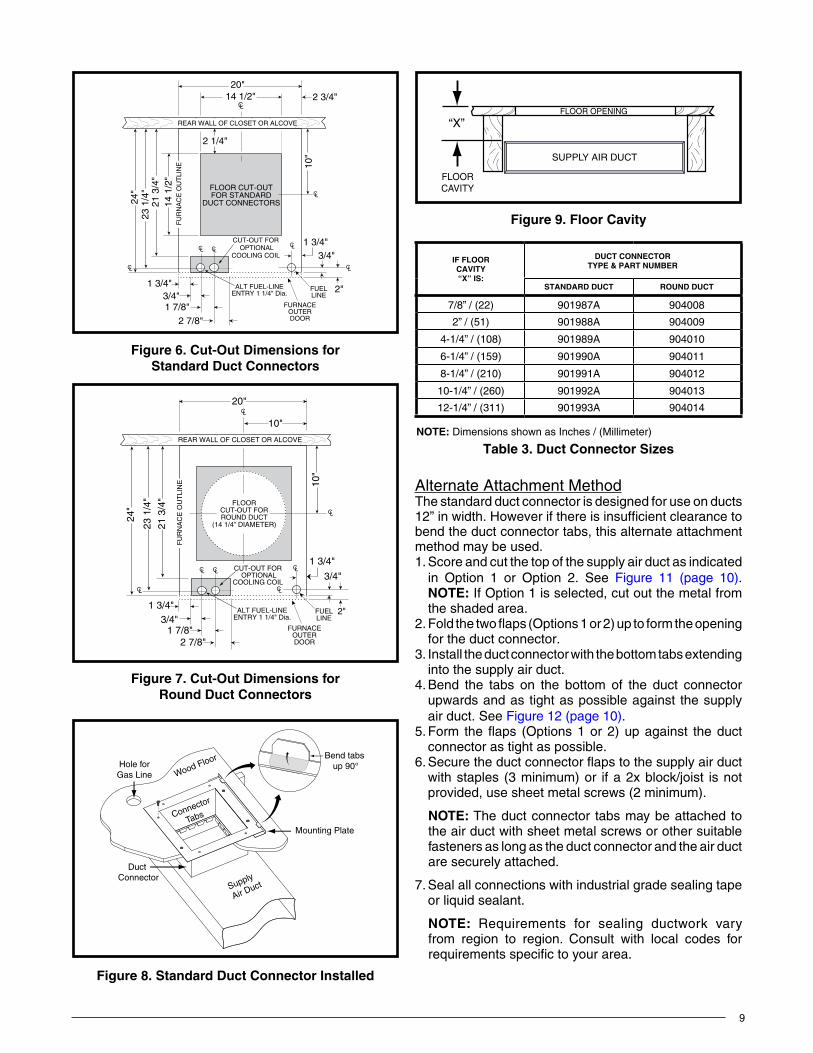
Locating&CuttingDuctOpeningsFloor cut-outs and fuel line holes must be carefully located to avoid misalignment of the furnace, and vent piping. To locate standard ducts see Figure 6 (page 9). For round ducts, see Figure 7.1. Measure 10” from the rear wall or alcove and mark the
centerlineofthecut-outonthefloor.2. Using the centerline as a starting point, draw the rest
of the duct cut-out to the dimensions shown in Figure 6 or Figure 7.
3.Cutouttheflooropening1/16”largerthantheactualcutout drawn. This will allow some clearance when installing the duct connector.
4.Measurefromthetopofthefloordowntothetopofthesupplyairducttoobtainthedepthofthefloorcavity.NOTE:Thedepthofthefloorcavityshownas“X”inFigure 9 (page 9) will determine the correct duct connector.
5. Determine which duct connector to use from Table 3 (page 9).
6. Measure and drill gas hole and cut out for cooling coil (if applicable). See Figure 6 or Figure 7.
Standard Duct Connector InstallationThe standard duct connector is designed for use on ducts 12” in width. However ducts narrower than 12” may not allow sufficient clearances for this type of installation. For an alternate installation method, see page 9.
1.Center the duct connector in the floor opening withbottom tabs resting on top of the supply air duct.
2. Mark the cut-out area on the supply air duct by tracing around the connector tabs of the duct connector. See Figure 8 (page 9).
3. Remove the duct connector and cut out the marked area of the supply air duct 1/4” larger the actual cutout drawn.
4.Installtheductconnectorbackintheflooropeningwiththe bottom tabs extending into the supply air duct.
5. Install the mounting plate under the back side of the duct connector as shown in Figure 8. Align the screw holes in both components.
6. Secure the duct connector and the mounting plate to thewoodfloorwithappropriatesizescrews.
7. Bend the connector tabs on the bottom of the duct connector upwards and as tight as possible against the supply air duct.
8. Bend both tabs up 90° on the mounting plate. See Figure 10 (page 10).
9. Seal all connections with industrial grade sealing tape or liquid sealant.
NOTE: Requirements for sealing ductwork vary from region to region. Consult with local codes for requirements specific to your area.
9
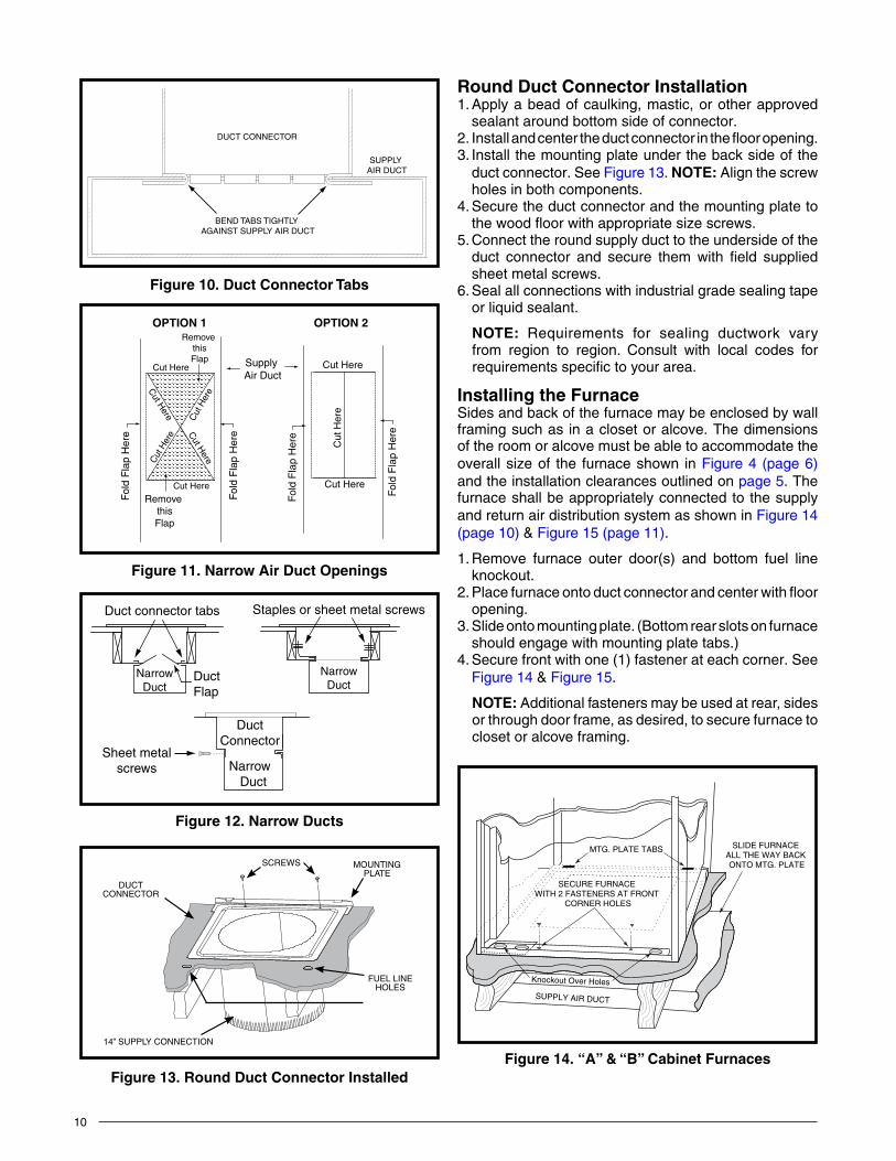
Alternate Attachment MethodThe standard duct connector is designed for use on ducts 12” in width. However if there is insufficient clearance to bend the duct connector tabs, this alternate attachment method may be used.1. Score and cut the top of the supply air duct as indicated
in Option 1 or Option 2. See Figure 11 (page 10). NOTE: If Option 1 is selected, cut out the metal from the shaded area.
2.Foldthetwoflaps(Options1or2)uptoformtheopeningfor the duct connector.
3. Install the duct connector with the bottom tabs extending into the supply air duct.
4. Bend the tabs on the bottom of the duct connector upwards and as tight as possible against the supply air duct. See Figure 12 (page 10).
5.Form theflaps (Options1or2)upagainst theductconnector as tight as possible.
6.Securetheductconnectorflapstothesupplyairductwith staples (3 minimum) or if a 2x block/joist is not provided, use sheet metal screws (2 minimum).
NOTE: The duct connector tabs may be attached to the air duct with sheet metal screws or other suitable fasteners as long as the duct connector and the air duct are securely attached.
7. Seal all connections with industrial grade sealing tape or liquid sealant.
NOTE: Requirements for sealing ductwork vary from region to region. Consult with local codes for requirements specific to your area.
FLOOR CUT-OUTFOR STANDARD
DUCT CONNECTORS
CL
CL
CL
24"
23 1
/4"
21 3
/4"
14 1
/2"
2 1/4"
2 3/4"20"
CUT-OUT FOR OPTIONAL
COOLING COIL
REAR WALL OF CLOSET OR ALCOVE
1 3/4"
2"
3/4"CL
CL
CL
10"
CL
FU
RN
AC
E O
UT
LIN
E
14 1/2"
ALT FUEL-LINEENTRY 1 1/4" Dia.
FURNACEOUTERDOOR
FUELLINE
1 3/4"3/4"1 7/8"
2 7/8"
Figure 6. Cut-OutDimensionsfor Standard Duct Connectors
FLOORCUT-OUT FORROUND DUCT
(14 1/4” DIAMETER)
CL
CL CL
CL
24"
23 1
/4"
21 3
/4"
20"
CUT-OUT FOR OPTIONAL
COOLING COIL
ALT FUEL-LINEENTRY 1 1/4" Dia.
FURNACEOUTERDOOR
REAR WALL OF CLOSET OR ALCOVE
FUELLINE
1 3/4"
2"
3/4"CL
CL
10"
FU
RN
AC
E O
UT
LIN
E
1 3/4"
10"
3/4"1 7/8"
2 7/8"
CL
Figure 7. Cut-OutDimensionsfor Round Duct Connectors
Bend tabs up 90°
Mounting Plate
Duct Connector
Connector
Tabs
Supply
Air Duct
Hole forGas Line Wood Floor
Figure 8. Standard Duct Connector Installed
“X”FLOOR OPENING
FLOORCAVITY
SUPPLY AIR DUCT
Figure 9. FloorCavity
Table 3IF FlOORCAVITY“X”IS:
DUCTCONNECTORTYPE&PARTNUMBER
StAnDARD DuCt ROunD DuCt
7/8” / (22) 901987A 904008
2” / (51) 901988A 904009
4-1/4” / (108) 901989A 904010
6-1/4” / (159) 901990A 904011
8-1/4” / (210) 901991A 904012
10-1/4” / (260) 901992A 904013
12-1/4” / (311) 901993A 904014
NOTE: Dimensions shown as Inches / (Millimeter)
table 3. DuctConnectorSizes
10
Round Duct Connector Installation1. Apply a bead of caulking, mastic, or other approved
sealant around bottom side of connector.2.Installandcentertheductconnectorintheflooropening.3. Install the mounting plate under the back side of the
duct connector. See Figure 13. NOTE: Align the screw holes in both components.
4. Secure the duct connector and the mounting plate to thewoodfloorwithappropriatesizescrews.
5. Connect the round supply duct to the underside of the duct connector and secure them with field supplied sheet metal screws.
6. Seal all connections with industrial grade sealing tape or liquid sealant.
NOTE: Requirements for sealing ductwork vary from region to region. Consult with local codes for requirements specific to your area.
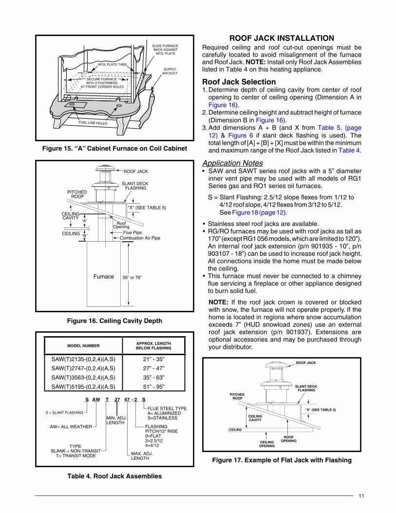
InstallingtheFurnaceSides and back of the furnace may be enclosed by wall framing such as in a closet or alcove. The dimensions of the room or alcove must be able to accommodate the overall size of the furnace shown in Figure 4 (page 6) and the installation clearances outlined on page 5. The furnace shall be appropriately connected to the supply and return air distribution system as shown in Figure 14 (page 10) & Figure 15 (page 11).
1. Remove furnace outer door(s) and bottom fuel line knockout.
2.Placefurnaceontoductconnectorandcenterwithflooropening.
3. Slide onto mounting plate. (Bottom rear slots on furnace should engage with mounting plate tabs.)
4. Secure front with one (1) fastener at each corner. See Figure 14 & Figure 15.
NOTE: Additional fasteners may be used at rear, sides or through door frame, as desired, to secure furnace to closet or alcove framing.
DUCT CONNECTOR
SUPPLY AIR DUCT
BEND TABS TIGHTLY AGAINST SUPPLY AIR DUCT
Figure10.Duct Connector tabs
Figure 11. NarrowAirDuctOpenings
OPTION 1 OPTION 2
Supply Air Duct
Fol
d F
lap
Her
e
Fol
d F
lap
Her
e
Remove thisFlap
Remove thisFlap
Cut
Her
e
Cut
Her
e Cut H
ere
Cut H
ere
Cut Here
Cut Here
Cut
Her
e
Cut Here
Cut Here
Fol
d F
lap
Her
e
Fol
d F
lap
Her
e
NarrowDuct
NarrowDuct
Duct connector tabs Staples or sheet metal screws
Duct Flap
Narrow Duct
DuctConnector
Sheet metal screws
Figure 12. narrow Ducts
DUCTCONNECTOR
MOUNTING PLATE
SCREWS
FUEL LINEHOLES
14” SUPPLY CONNECTION
Figure 13. Round Duct Connector Installed
MTG. PLATE TABS SLIDE FURNACE ALL THE WAY BACK ONTO MTG. PLATE
SUPPLY AIR DUCT
Knockout Over Holes
SECURE FURNACE WITH 2 FASTENERS AT FRONT
CORNER HOLES
Figure 14. “A”&“B”CabinetFurnaces
11
ROOFJACKINSTALLATIONRequired ceiling and roof cut-out openings must be carefully located to avoid misalignment of the furnace and Roof Jack. NOTE:Install only Roof Jack Assemblies listed in Table 4 on this heating appliance.
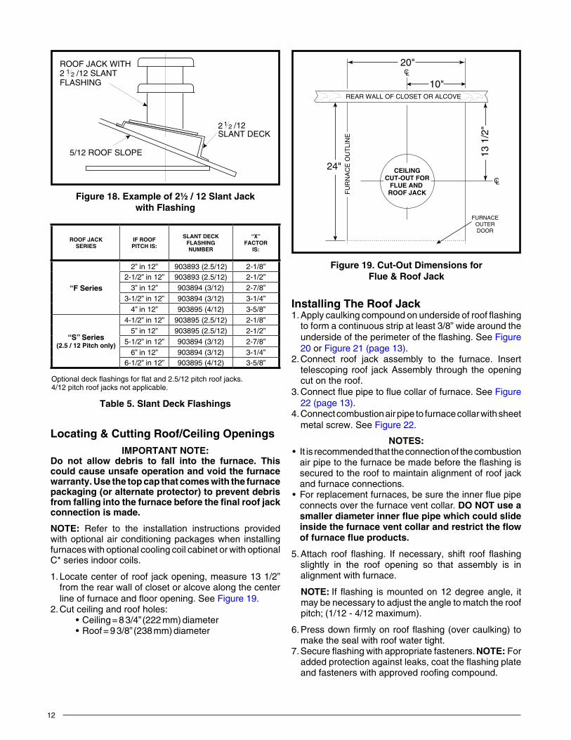
RoofJackSelection1. Determine depth of ceiling cavity from center of roof
opening to center of ceiling opening (Dimension A in Figure 16).
2. Determine ceiling height and subtract height of furnace (Dimension B in Figure 16).
3.Add dimensions A + B (and X from Table 5, (page 12) & Figure 6 if slant deck flashing is used). Thetotallengthof[A]+[B]+[X]mustbewithintheminimumand maximum range of the Roof Jack listed in Table 4.
Application Notes• SAWandSAWTseriesroofjackswitha5”diameter
inner vent pipe may be used with all models of RG1 Series gas and RO1 series oil furnaces.
S=SlantFlashing:2.5/12slopeflexesfrom1/12to4/12roofslope,4/12flexesfrom3/12to5/12.See Figure 18 (page 12).
• Stainlesssteelroofjacksareavailable.• RG/ROfurnacesmaybeusedwithroofjacksastallas
170” (except RG1 056 models, which are limited to 120”). An internal roof jack extension (p/n 901935 - 10”, p/n 903107 - 18”) can be used to increase roof jack height. All connections inside the home must be made below the ceiling.
• This furnacemustneverbeconnectedtoachimneyflueservicingafireplaceorotherappliancedesignedto burn solid fuel.
NOTE: If the roof jack crown is covered or blocked with snow, the furnace will not operate properly. If the home is located in regions where snow accumulation exceeds 7” (HUD snowload zones) use an external roof jack extension (p/n 901937). Extensions are optional accessories and may be purchased through your distributor.
FUEL LINE HOLES
MTG. PLATE TABS
SLIDE FURNACE BACK AGAINST
MTG. PLATE
SECURE FURNACE WITH 2 FASTENERS
AT FRONT CORNER HOLES
SUPPLYAIR DUCT
Figure 15. “A”CabinetFurnaceonCoilCabinet
ROOF JACK
SLANT DECK FLASHING
PITCHED ROOF
CEILING
CEILINGCAVITY
RoofOpening
"X" (SEE TABLE 5)
Flue PipeCombustion Air Pipe
56" or 76"Furnace
“A”
“B”
Figure 16. CeilingCavityDepth
Figure 17. ExampleofFlatJackwithFlashing
ROOF JACK
SLANT DECK FLASHING
PITCHED ROOF
CEILING
ROOFOPENING
"X" (SEE TABLE 5)
CEILINGCAVITY
CEILINGOPENING
Table 4
table 4. RoofJackAssemblies
S SAW T 27 47 - 2
AW= ALL WEATHER FLASHINGPITCH/12" RISE0=FLAT2=2.5/124=4/12
MIN. ADJ.LENGTH
S = SLANT FLASHING
TYPE:BLANK = NON-TRANSIT
T= TRANSIT MODE MAX. ADJ.LENGTH
FLUE STEEL TYPEA= ALUMINIZEDS=STAINLESS
MODELNUMBER APPROX.LENGTHBELOWFLASHING
SAW(T)2135-(0,2,4)(A,S) 21” - 35”
SAW(T)2747-(0,2,4)(A,S) 27” - 47”
SAW(T)3563-(0,2,4)(A,S) 35” - 63”
SAW(T)5195-(0,2,4)(A,S) 51” - 95”
12
Locating&CuttingRoof/CeilingOpeningsIMPORTANTNOTE:
Do not allow debris to fall into the furnace. Thiscouldcauseunsafeoperationandvoidthefurnacewarranty.Usethetopcapthatcomeswiththefurnacepackaging(oralternateprotector)topreventdebrisfromfallingintothefurnacebeforethefinalroofjackconnection is made.
NOTE: Refer to the installation instructions provided with optional air conditioning packages when installing furnaces with optional cooling coil cabinet or with optional C* series indoor coils.
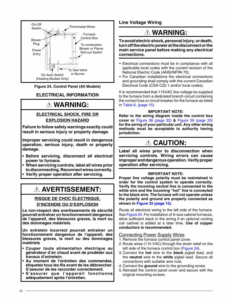
1. Locate center of roof jack opening, measure 13 1/2” from the rear wall of closet or alcove along the center lineoffurnaceandflooropening.SeeFigure 19.
2. Cut ceiling and roof holes:•Ceiling=83/4”(222mm)diameter•Roof=93/8”(238mm)diameter
InstallingTheRoofJack1.Applycaulkingcompoundonundersideofroofflashing
to form a continuous strip at least 3/8” wide around the undersideoftheperimeteroftheflashing.SeeFigure 20 or Figure 21 (page 13).
2. Connect roof jack assembly to the furnace. Insert telescoping roof jack Assembly through the opening cut on the roof.
3.Connectfluepipetofluecollaroffurnace.SeeFigure 22 (page 13).
4. Connect combustion air pipe to furnace collar with sheet metal screw. See Figure 22.
NOTES:• Itisrecommendedthattheconnectionofthecombustion
airpipetothefurnacebemadebeforetheflashingissecured to the roof to maintain alignment of roof jack and furnace connections.
• Forreplacementfurnaces,besuretheinnerfluepipeconnects over the furnace vent collar. DO nOt use a smallerdiameterinnerfluepipewhichcouldslideinsidethefurnaceventcollarandrestricttheflowoffurnaceflueproducts.
5.Attach roof flashing. If necessary, shift roof flashingslightly in the roof opening so that assembly is in alignment with furnace.
NOTE: Ifflashing ismountedon12degreeangle, itmay be necessary to adjust the angle to match the roof pitch; (1/12 - 4/12 maximum).
6.Pressdownfirmlyonroofflashing(overcaulking)tomake the seal with roof water tight.
7.Secureflashingwithappropriatefasteners. NOTE:For addedprotectionagainstleaks,coattheflashingplateand fasteners with approved roofing compound.
Figure 18. Exampleof2½/12SlantJack withFlashing
5/12 ROOF SLOPE
2SLANT DECK
/121 2
ROOF JACK WITH2FLASHING
/12 SLANT1 2
CEILINGCUT-OUT FOR
FLUE AND ROOF JACK
CL
CL
24"
20"
13 1
/2"
REAR WALL OF CLOSET OR ALCOVE
10"
FURNACEOUTERDOOR
FU
RN
AC
E O
UT
LIN
E
Figure 19. Cut-OutDimensionsfor Flue&RoofJack
Table 5
table 5. SlantDeckFlashings
ROOFJACKSERIES
IF ROOFPITCHIS:
SLANTDECKFLASHINGNUMBER
“X”FACtOR
IS:
“F Series
2” in 12” 903893 (2.5/12) 2-1/8”2-1/2” in 12” 903893 (2.5/12) 2-1/2”
3” in 12” 903894 (3/12) 2-7/8”3-1/2” in 12” 903894 (3/12) 3-1/4”
4” in 12” 903895 (4/12) 3-5/8”
“S”Series(2.5/12Pitchonly)
4-1/2” in 12” 903895 (2.5/12) 2-1/8”5” in 12” 903895 (2.5/12) 2-1/2”
5-1/2” in 12” 903894 (3/12) 2-7/8”6” in 12” 903894 (3/12) 3-1/4”
6-1/2” in 12” 903895 (4/12) 3-5/8”
Optionaldeckflashingsforflatand2.5/12pitchroofjacks.4/12 pitch roof jacks not applicable.

13
Upper Roof Jack SectionSecure lower roofjack section with
no. 10 S.M. screws
Caulk under roof�ashing to prevent
water leakage
Optional SlantDeck Flashing
Secure �ashingwith appropriate
fasteners
Ceiling
Figure 21. PitchedRoof
InstallationofTransit-ModeVentingSystem(ManufacturedHomeFactory)1. Furnace must be installed in accordance to furnace
installation manual.2. Select appropriate roof jack from Table 4, (page 11)3. Roof Jack (less upper roof jack crown), with weather
cap to be installed as described under Install Roof Jack.
NOTE: Upper roof jack crown to be stored in a prominent location inside manufactured home until on-site installation.
4. The four warning tags supplied must be installed as follows:
•Toweathercap•To fuel line connection point (Gas) or furnace
burner (Oil)•Tofurnaceflameobservationdoor(GasorOil)•Tofurnacewallthermostat
5. Transit-mode weather cap to be removed and upper roof jack crown installed. See Figure 23. Do Not Discard screws.
6.Placeupperroofjack(crown)onthefluepipeassembly.
NOTE:Makesureinsidefluepipeattachesoverinnerfluepipeandouterroofjackpipefitsoverouterpipe.
7. Secure in place using three, #10, 1/2” sheet metal screws removed in step 5. Do not use the same holes which secured the rain cap in place.
8. Remove and discard venting system warning tags.
WARnInG:Failure to properly secure the flue pipe tothe furnace may result in fire, explosion orasphyxiationwhenoperatingthefurnace.
SCREWS
COMPLETEDASSEMBLY
TO FURNACE
UPPER ROOFJACK (CROWN)
INNER FLUEPIPE
FLUE ASSEMBLY
OUTER PIPE
FLASHING
WEATHER CAP
Figure 23. RoofJackCrown
Secure roof jack withappropriate fasteners
after connecting tofurnace
Caulk under roofflashing to prevent
water leakage
Roof
Ceiling
Optional 2-piece ceiling ring #902521
Figure20.FlatRoof
Figure 22. CombustionAirPipeConnection
14
line Voltage Wiring
WARnInG:Toavoidelectricshock,personalinjury,ordeath,turnofftheelectricpoweratthedisconnectorthemainservicepanelbeforemakinganyelectricalconnections.
• Electricalconnectionsmustbeincompliancewithallapplicable local codes with the current revision of the National Electric Code (ANSI/NFPA 70).
• ForCanadian installations theelectrical connectionsand grounding shall comply with the current Canadian Electrical Code (CSA C22.1 and/or local codes).
It is recommended that 115VAC line voltage be supplied to the furnace from a dedicated branch circuit containing the correct fuse or circuit breaker for the furnace as listed in Table 6, (page 15).
IMPORTANTNOTE:Refer to thewiringdiagram inside thecontrolboxcover or Figure 38 (page 32) & Figure 39 (page 33) forthewiringofyourparticularunit.Anyotherwiringmethods must be acceptable to authority havingjurisdiction.
CAutIOn:Label all wires prior to disconnection whenservicing controls. Wiring errors can causeimproperanddangerousoperation.Verifyproperoperationafterservicing.
IMPORTANTNOTE:Proper linevoltagepolaritymustbemaintained inorder for the control system to operate correctly.Verifytheincomingneutrallineisconnectedtothewhitewireandtheincoming“hot”lineisconnectedtotheblackwire.ThefurnacewillnotoperateunlessthepolarityandgroundareproperlyconnectedasshowninFigure25(page15).
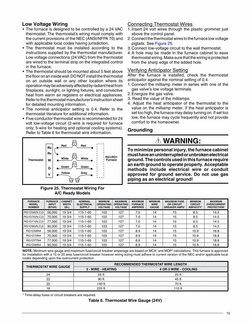
Route all electrical wiring to the left side of the furnace. See Figure 24. For installation of A-size cabinet furnaces, allow sufficient slack in the wiring if an optional cooling coil cabinet is added at a later time. Use of copperconductors is recommended.
Connecting Power Supply Wires1. Remove the furnace control panel cover.2. Route wires (115 VAC) through the strain relief on the
left side of the furnace control box (Figure 24).3. Connect the hot wire to the black pigtail lead, and
the neutral wire to the white pigtail lead. Secure all connections with suitable wire nuts.
4. Connect the ground wire to the grounding screw.5. Reinstall the control panel cover and secure with the
original mounting screws.
Figure 24. ControlPanel(AllModels)
On-OffSwitch
BlowerPlug
PowerEntry
On-Auto Switch(Heating Models Only)
Thermostat Wires
FurnaceControl Box
To combustionBlower or FlameRoll-out Switch
To Gas Valveor Burner
ELECTRICALINFORMATION
WARnInG:ELECTRICALSHOCK,FIREOR
EXPLOSIONHAZARD
Failuretofollowsafetywarningsexactlycouldresultinseriousinjuryorpropertydamage.
Improperservicingcouldresultindangerousoperation, serious injury, death or propertydamage.
• Before servicing, disconnect all electricalpowertofurnace.
• Whenservicingcontrols,labelallwirespriortodisconnecting.Reconnectwirescorrectly.
• Verifyproperoperationafterservicing.
AVERTISSEMENT:RISQUEDECHOCÉLECTRIQUE,D’INCENDIEOUD’EXPLOSION
Lenon-respectdesavertissementsdesécuritépourraitentraînerunfonctionnementdangereuxdel’appareil,desblessuresgraves,lamortoudesdommagesmatériels.
Un entretein incorrect pourrait entraîner unfonctionnement dangereux de l’appareil, desblessures graves, la mort ou des dommagesmatériels• Couper toute alimentation électrique au
générateurd’airchaudavantdeprodéderauxtravauxd’entretein.
• Au moment de l’entretien des commandes,étiqueteztouslesfilsavantdelesdébrancher.S’assurerdelesraccordercorrectement.
• S’assurer que l ’apparei l fonct ionneadéquatementaprésl’entretien.
15
low Voltage Wiring• Thefurnaceisdesignedtobecontrolledbya24VAC
thermostat.Thethermostat’swiringmustcomplywiththe current provisions of the NEC (ANSI/NFPA 70) and with applicable local codes having jurisdiction.
• The thermostat must be installed according to theinstructions supplied by the thermostat manufacturer. Low voltage connections (24 VAC) from the thermostat are wired to the terminal strip on the integrated control in the furnace.
• Thethermostatshouldbemountedabout5feetabovetheflooronaninsidewall.DONOTinstallthethermostaton an outside wall or any other location where its operation may be adversely affected by radiant heat from fireplaces, sunlight, or lighting fixtures, and convective heat from warm air registers or electrical appliances. Refertothethermostatmanufacturer’sinstructionsheetfor detailed mounting information.
• The nominal anticipator setting is 0.4. Refer to thethermostat literature for additional information.
• Five-conductorthermostatwireisrecommendedfor24volt low-voltage circuit (2-wire is required for furnace only; 5-wire for heating and optional cooling systems). Refer to Table 6 for thermostat wire information.
Connecting Thermostat Wires1. Insert 24 volt wires through the plastic grommet just
above the control panel.2. Connect the thermostat wires to the furnace low voltage
pigtails. See Figure 25.3. Connect low-voltage circuit to the wall thermostat.4. A hole may be made in the furnace cabinet to ease
thermostat wiring. Make sure that the wiring is protected from the sharp edge of the added hole.
Verifying Anticipator SettingAfter the furnace is installed, check the thermostat anticipator against the nominal setting of 0.4.1. Connect the milliamp meter in series with one of the
gasvalve’slowvoltageterminals.2. Energize the gas valve.3. Read the value of the milliamps.4. Adjust the heat anticipator of the thermostat to the
value on the milliamp meter. If the heat anticipator is set too high, the furnace may delay turning on. If set too low, the furnace may cycle frequently and not provide comfort to the homeowner.
Grounding
WARnInG:Tominimizepersonalinjury,thefurnacecabinetmusthaveanuninterruptedorunbrokenelectricalground.Thecontrolsusedinthisfurnacerequireanearthgroundtooperateproperly.Acceptablemethods include electrical wire or conduitapproved for ground service. Do not use gaspipingasanelectricalground!
Figure 25. ThermostatWiringFor A/CReadyModels
Rc
RH
W
G
Y
Red
White
Green
Yellow
Red
White
Green
Grey
ThermostatRG1/RO1Furnace
Table 6
table 6. ThermostatWireGauge(24V)
FURNACEMODEL
NUMBER
FURNACEINPUT(BTUH)
CABINETWIDTH
(In.)
NOMINALELECTRICAL
SUPPLY
MINIMUMOPERATINGVOLTAGE
MAXIMUMOPERATINGVOLTAGE
MAXIMUMFURNACEAMPERES
MINIMUMWIRE
GAUGE
MAXIMUMFUSEOR CIRCuIt
BREAKERAMPS*
MINIMUMCIRCuIt
AMPACITY1
MAXIMUMOVERCURRENTPROTECTION2
RG1D56(N,C)3 56,000 19 3/4 115-1-60 103 127 7.0 14 15 8.5 14.5RG1D70(N,C)3 70,000 19 3/4 115-1-60 103 127 7.0 14 15 8.5 14.5RG1D77(N,C)3 77,000 19 3/4 115-1-60 103 127 7.0 14 15 8.5 14.5RG1D90(N,C)3 90,000 19 3/4 115-1-60 103 127 7.0 14 15 8.5 14.5
RG1D56N4 56,000 19 3/4 115-1-60 103 127 8.9 14 15 10.9 18.8RG1D70N4 70,000 19 3/4 115-1-60 103 127 8.9 14 15 10.9 18.8RG1D77N4 77,000 19 3/4 115-1-60 103 127 8.9 14 15 10.9 18.8RG1D90N4 90,000 19 3/4 115-1-60 103 127 8.9 14 15 10.9 18.8
NOTE: Minimum wire gauge and maximum fuse/circuit breaker amperage are based on MCA1 and MOP2 calculations. This furnace is approved for installation with a 15 or 20 amp fuse/circuit breaker however wiring sizing must adhere to current version of the NEC and/or applicable local codes depending upon the overcurrent protection.
THERMOSTATWIREGAUGERECOMMENDEDTHERMOSTATWIRELENGTH
2-WIRE-HEATING 4OR5WIRE-COOLING
24 55 ft. 25 ft.22 90 ft. 45 ft.20 140 ft. 70 ft.18 225 ft. 110 ft.
* Time-delay fuses or circuit breakers are required.
16
FUELSUPPLY&PIPING
WARnInG:Allpipingmustconformwithlocalbuildingcodes,orintheabsenceoflocalcodes,withthemostrecent edition of the National Fuel Gas CodeANSIZ223.1or(CAN/CGAB149.1or.2).Failuretofollowallsafetywarningscouldresultinseriousinjury,deathorpropertydamage.
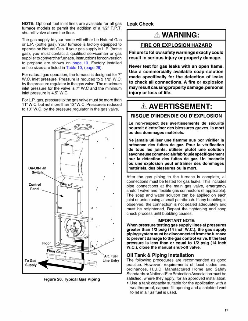
This furnace may be installed with left, right, or bottom gas entry. When connecting the gas supply, provide clearance between the gas supply line and the entry hole in the furnace casing to avoid unwanted noise and/or damage to the furnace. Typical gas service hookup for this furnace is shown in Figure 26 (page 17).
Table 14, (page 31)listsgasflowcapacitiesforstandardpipe sizes as a function of length in typical applications based on nominal pressure drop in the line.
IMPORTANTNOTES:• Somelocalregulationsrequiretheinstallationofa
manualmainshut-offvalveandgroundjointunionexternal to the furnace.SeeFigure27 (page18). Theshut-offvalveshouldbereadilyaccessibleforserviceand/oremergencyuse.Consult the localutilityorgassupplierforadditionalrequirementsregardingplacementofthemanualmaingasshut-off.
• Gaspipingmustneverruninorthroughairducts,chimneys,gasvents,orelevatorshafts.
• Compoundsusedonthreadedjointsofgaspipingmust be resistant to the actions of -liquefiedpetroleumgases.
• Themaingasvalveandmainpowerdisconnecttothefurnacemustbeproperlylabeledbytheinstallerincaseemergencyshutdownisrequired.
• Flexiblegasconnectorsarenotrecommendedforthis furnacebutmaybeused ifallowedby localjurisdiction.Onlynewflexibleconnectorsmaybeused.DONOTreuseoldflexiblegasconnectors.
• Adriplegisrecommendedforaverticalruntotheunit.
• Allpipingshallbeblackironpipe,orequivalentlysizedsteeltubing.Internallytinnedcoppertubingmaybeusedforgassupplysystems.
• Fuellineinstallationsotherthantypicalinstallationsshown in Figure 26 (page 17) & Figure 27 (page18) must comply with the fuel piping provisionsstatedintheFederalManufacturedHomeStandard(H.U.D.TITLE24,PART280)andtheNationalFuelGasCode(ANSI-Z223.1/NFPA-54).
• Shut-offvalvemustbedesignedandlistedforusewithliquidpetroleum(L.P.gas).
• A 1/8” NPT plugged tappings for test gaugeconnectionarepresentonthegasvalve.SeeFigure 28(page20)forlocations
WARnInG:FIREOREXPLOSIONHAZARD
•Failuretofollowsafetywarningsexactlycouldresultinseriousinjuryorpropertydamage.
• Installationandservicemustbeperformedbyaqualifiedinstaller,serviceagencyorthegassupplier.
•Do not store or use gasoline or otherflammablevaporsandliquidsinthevicinityofthisoranyotherappliance.
WHATTODOIFYOUSMELLGAS•Donottrytolightanyappliance.•Donot touchanyelectrical switch;donot
useanyphoneinyourbuilding.•Leavethebuildingimmediately.• Immediately call your gas supplier from a
neighbor’sphone.Followthegassupplier’sinstructions.
• Ifyoucannot reachyourgassupplier,callthefiredepartment.
AVERTISSEMENT:
RISQUED’INCENDIEOUD’EXPLOSION•Lenon-respectdesavertissementsdesécurité
pourraitentraînerdesblessuresgraves,lamortoudesdommagesmatériels.
•L’installationetl’entretiendoiventêtreeffectuésparun installateurqualifié,unorganismedeserviceoulefournisseurdegazstaller,serviceagencyorthegassupplier.
•Nepasentreposerniutiliserde l’essencenid’autresvapeursouliquidesinflammablesdanslevoisinagedecetappareil,nide toutautreappareil.QUEFAIRES’ILYAUNEODEURDEGAZ
•Nepastenterd’allumeraucunappareil.•Ne toucher à aucun interrupteur électrique;
n’utiliseraucuntéléphonedanslebâtiment.•Évacuerl’immeubleimmédiatement.•Appelerimmédiatementlefournisseurdegazen
employantletéléphoned’unvoisin.Respecteràlalettrelesinstructionsdufournisseurdegaz.
•Sipersonnenerépond,appelerleservicedesincendies.
17
FIREOREXPLOSIONHAZARDFailuretofollowsafetywarningsexactlycouldresultinseriousinjuryorpropertydamage.
Nevertestforgasleakswithanopenflame.Useacommerciallyavailablesoapsolutionmadespecifically for thedetectionof leakstocheckallconnections.Afireorexplosionmayresultcausingpropertydamage,personalinjuryorlossoflife.
WARnInG:
RISQUED’INDENDIEOUD’EXPLOSIONLe non-respect des avertissements de sécuritépourraitd’entraînerdesblessuresgraves,lamortoudesdommagesmatériels.
Nejamaisutiliseruneflammenueporvérifier laprésence des fuites de gaz. Pour la vérificationde tous les joints, utiliser plutôt une solutionsavonneusecommercialefabriquéespécifiquementpur la détection des fuites de gaz. Un incendieouuneexplosionpeutentraînerdesdommagesmatériels,desblessuresoulamort.
AVERTISSEMENT:
LeakCheckNOTE: Optional fuel inlet lines are available for all gas furnace models to permit the addition of a 1/2” F.P.T. shut-offvalveabovethefloor.
The gas supply to your home will either be Natural Gas or L.P. (bottle gas). Your furnace is factory equipped to operate on Natural Gas. If your gas supply is L.P. (bottle gas), you must contact a qualified serviceman or gas supplier to convert the furnace. Instructions for conversion to propane are shown on page 19. Factory installed orifice sizes are listed in Table 10, (page 29).
For natural gas operation, the furnace is designed for 7” W.C. inlet pressure. Pressure is reduced to 3 1/2” W.C. by the pressure regulator in the gas valve. The maximum inlet pressure for the valve is 7” W.C and the minimum inlet pressure is 4.5” W.C.
For L.P. gas, pressure to the gas valve must be more than 11” W.C. but not more than 13” W.C. Pressure is reduced to 10” W.C. by the pressure regulator in the gas valve.
To Gas Supply
Floor
ControlPanel
On-Off-FanSwitch
Alt. FuelLine Entry
Floor Cavity
Figure 26. TypicalGasPiping
After the gas piping to the furnace is complete, all connections must be tested for gas leaks. This includes pipe connections at the main gas valve, emergency shutoffvalveandflexiblegasconnectors(ifapplicable).The soap and water solution can be applied on each joint or union using a small paintbrush. If any bubbling is observed, the connection is not sealed adequately and must be retightened. Repeat the tightening and soap check process until bubbling ceases.
IMPORTANTNOTE:Whenpressuretestinggassupplylinesatpressuresgreaterthan1/2psig(14inchW.C.),thegassupplypipingsystemmustbedisconnectedfromthefurnacetopreventdamagetothegascontrolvalve.Ifthetestpressure is less thanorequal to1/2psig (14 inchW.C.),closethemanualshut-offvalve.
OilTank&PipingInstallationThe following procedures are recommended as good practice. However, requirements of local codes and ordinances, H.U.D. Manufactured Home and Safety Standards or National Fire Protection Association must be satisfied, where they apply, for an approved installation.• Useatankcapacitysuitablefortheapplicationwitha
weatherproof, capped fill opening and a shielded vent to let in air as fuel is used.
18
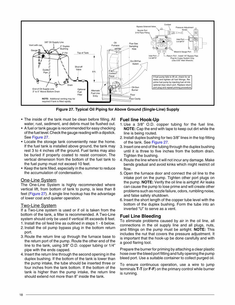
Figure 27. TypicalOilPipingforAboveGround(Single-Line)Supply
If fuel pump fails to lift oil, check for air
port plug and repeat priming procedure.
leaks and tighten all fuel fittings. Re-prime fuel pump by injecting fuel oil intooptional (top) return port. Replace return
Top of Tank
8 ft.
Shut-offValve
OptionalFuelFilter
AlternateFuel Line
Entry
ControlPanel
Oil Furnace
On-Off-FanSwitch
Floor Cavity
Oil-GunBurner
Floor
Flue GasSampling
Hole
Drain
End of Oil Supply Line3" to 5" Above Bottom Drain
GuidePipe
Gauge
Vent with cap 2" DuplexBushing
2" Fill
3/8" Oil Supply Line
NOTE: Additional venting may be required if tank is filled rapidly.
4 GPH 100-150 PSI 3450 RPM
3 GPH 150-200 PSI 3450 RPM
VALVE ON DELAY
NO. 2 & LIGHTER FUEL
USE ONLY WITH
INLET BY-PASS
Exclusively for BeckettMade by Suntec
INLET
NO. 2 FUEL
A2EA-6520
Beckett
Nozzle Port3/16 Flare Fitting
Bypass Solenoid ValveCordset
Inlet Port1/4 NPTF
Bleed & Gauge Port
Pressure AdjustmentScrew
Inlet Port1/4 NPTF
Return Port - Install 1/6” Bypass PipePlug for 2-pipe System Only.
(Use 5/32” Allen Wrench)
• Theinsideofthetankmustbecleanbeforefilling.Allwater,rust,sediment,anddebrismustbeflushedout.
• Afuelortankgaugeisrecommendedforeasycheckingof the fuel level. Check the gauge reading with a dipstick. See Figure 27.
• Locatethestoragetankconvenientlynearthehome.If the fuel tank is installed above ground, the tank may rest 3 to 4 inches off the ground. Fuel tanks may also be buried if properly coated to resist corrosion. The vertical dimension from the bottom of the fuel tank to the fuel pump must not exceed 10 feet.
• Keepthetankfilled,especiallyinthesummertoreducethe accumulation of condensation.
One-Line SystemThe One-Line System is highly recommended where vertical lift, from bottom of tank to pump, is less than 8 feet (Figure 27). A single line hookup has the advantage of lower cost and quieter operation.
Two-Line SystemIf a Two-Line system is used or if oil is taken from the bottom of the tank, a filter is recommended. A Two-Line system should only be used if vertical lift exceeds 8 feet.1. Install the oil feed line as outlined in steps 1 - 6 below.2. Install the oil pump bypass plug in the bottom return
port.3. Route the return line up through the furnace base to
the return port of the pump. Route the other end of the line to the tank, using 3/8” O.D. copper tubing or 1/4” pipe with the ends capped.
4. Insert the return line through the second opening in the duplex bushing. If the bottom of the tank is lower than the pump intake, the tube should be inserted three or four inches from the tank bottom. If the bottom of the tank is higher than the pump intake, the return line should extend not more than 8” inside the tank.
FuellineHook-Up1. Use a 3/8” O.D. copper tubing for the fuel line.
NOTE: Cap the end with tape to keep out dirt while the line is being routed.
2. Install duplex bushing for two 3/8” lines in the top fitting of the tank. See Figure 27.
3. Insert one end of the tubing through the duplex bushing until it is three to five inches from the bottom drain. Tighten the bushing.
4. Route the line where it will not incur any damage. Make bends gradual and avoid kinks which might restrict oil flow.
5. Open the furnace door and connect the oil line to the intake port on the pump. Tighten other port plugs on the pump. NOTE: Verify the oil line is airtight! Air leaks can cause the pump to lose prime and will create other problems such as nozzle failure, odors, rumbling noise, and false safety shutdown.
6. Insert the short length of the copper tube level with the bottom of the duplex bushing. Form the tube into an inverted “U” to serve as a vent.
Fuel line BleedingTo eliminate problems caused by air in the oil line, all connections in the oil supply line and all plugs, nuts, and fittings on the pump must be airtight. NOTE: This includes the nut that covers the pressure adjustment. It is important that the hook-up be done carefully and with agoodflaringtool.
Prepare the burner for priming by attaching a clear plastic hose over the bleed port fitting and fully opening the pump bleed port. Use a suitable container to collect purged oil.
To ensure continuous operation, use a wire to jump terminals T-T (or F-F) on the primary control while burner is running.
19
Priming furnaces equipped with HoneywellR7184 primary control:1. While the ignition is on, press for 1/2 second (or less),
and release the reset button. The lockout time will be extended to 4 minutes.
2. If prime is not established within the 4 minutes, the control will lock out. Press the reset button to reset the control.
3. Repeat steps 1 & 2 (if needed) until the oil pump is fully primed.
Priming furnaces equipped with Beckett 7505 primary control1. After the burner starts, press and hold the reset button
until the yellow LED turns on (15 seconds). This indicates that the button has been held long enough.
2. Release the reset button. The yellow LED will turn off and the burner will start up again.
3. At burner start up, click the reset button while the igniter is still on. This transitions the control to a dedicated pump prime mode, during which the motor, igniter and valve are powered for 4 minutes. The yellow LED will be on. NOTE: If prime is not established during the four minute pump prime mode, repeat step 3 until the oil pump is fully primed.
4.Whenoilflow isclearand freeofairbubbles,closeair-bleed valve and tighten. NOTE: Air bleed out time will varies depending on length of oil line, number of bends, etc.
FuelOilType
WARnInG:Donotusegasoline,crankcaseoil,oranyoilcontaininggasline.Failuretokeepsupplyofoilcleanbyvariousproceduresdescribedabovemaycausefailureofcertaincomponentssuchasthefuelpumpgears,checkvalve,shaftseal,orburnernozzlewhichmayresultinaburnerfire.
Do not use fuel oil heavier than Grade No. 2. In areas where the oil supply is subject to low temperatures, Grade No. 1 may be used.
ConversiontoPropane(LP)Gas
CAutIOn:Furnace conversion must be performed by aqualified technician. Improperconversioncancauseunsafeoperation,explosion,fireand/orasphyxiation.
This gas fired heating appliance was shipped from the factory for use with natural gas. However, the appliance can be converted for use with LP gas. Use the following procedure for gas conversion of the burner.
Atmospheric & Direct Ignition Furnaces1. Follow the instructions “How to Shut Off Gas” (page
22).2. Disconnect the gas pipe union and the electrical wires
connected to the gas valve.3. Remove the gas valve assembly:
a. Remove screw(s) from gas valve bracket. Gas valve and spud may be removed. Orifice is located at the end of the spud (RG1 Models)
5. Replace the main orifice with the L.P. gas orifice supplied in the envelope located by the gas valve. Verify the orifice size matches the nameplate or Table 10, (page 29).
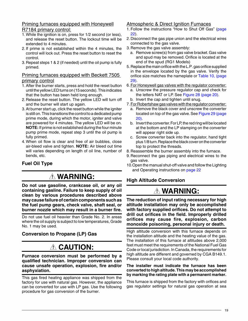
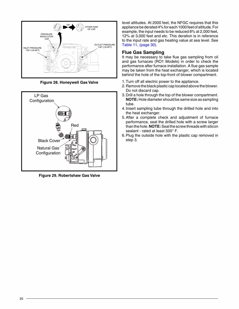
6. For Honeywell gas valves with the regulator converter: a. Unscrew the pressure regulator cap and check for
the letters NAT or LP. See Figure 28 (page 20).b. Invert the cap and tighten until snug.
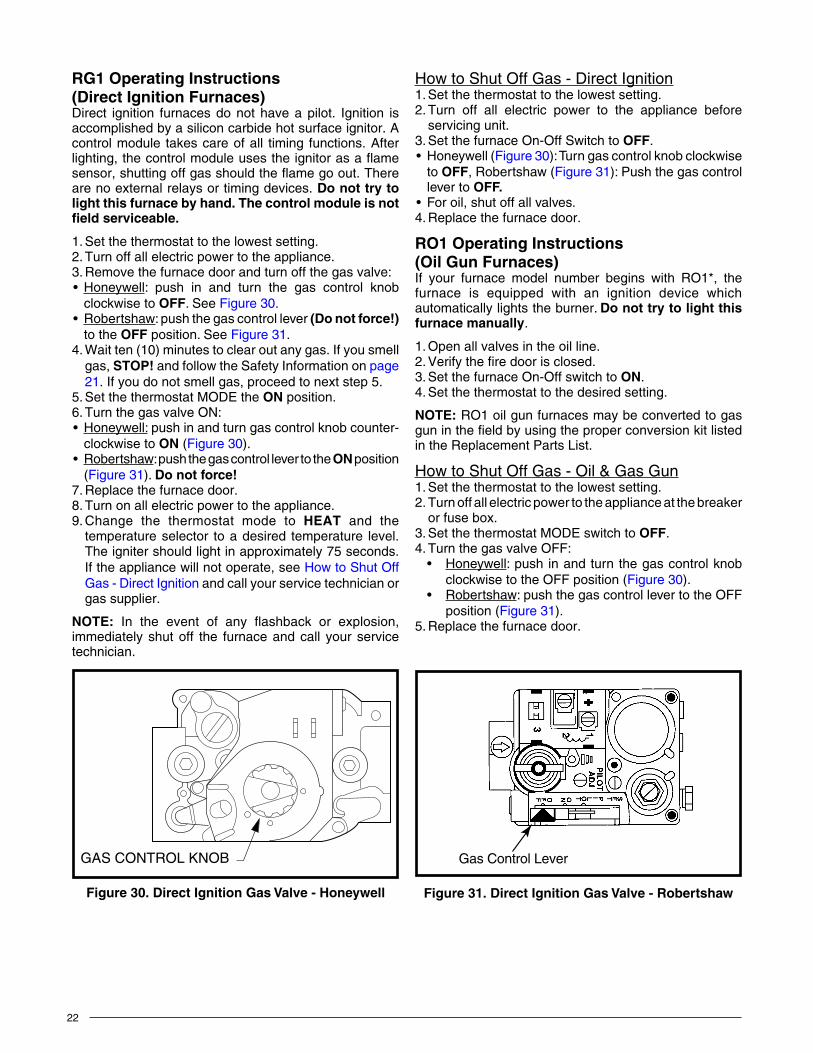
7. For Robertshaw gas valves with the regulator converter: a. Remove the black cover and unscrew the converter
located on top of the gas valve. See Figure 29 (page 20).
b. Invert the converter. For LP, the red ring will be located at the bottom and the LP stamping on the converter will appear right side up.
c. Screw converter back into the regulator, hand tight plus 1/8 turn. Replace the black cover on the converter top to protect the threads.
8. Reassemble the burner assembly into the furnace.9. Reconnect the gas piping and electrical wires to the
gas valve.10. Open the manual shut-off valve and follow the Lighting
and Operating instructions on page 22
HighAltitudeConversion
WARnInG:Thereductionofinputratingnecessaryforhighaltitudeinstallationmayonlybeaccomplishedwithfactorysuppliedorifices.Donotattempttodrilloutorificesinthefield.Improperlydrilledorifices may cause fire, explosion, carbonmonoxidepoisoning,personalinjuryordeath.
High altitude conversion with this furnace depends on the installation altitude and the heating value of the gas. The installation of this furnace at altitudes above 2,000 feet must meet the requirements of the National Fuel Gas Code or local jurisdiction. In Canada, the requirements for high altitude are different and governed by CGA B149.1. Please consult your local code authority.
The installer must indicate the furnace has beenconvertedtohighaltitude.Thismaybeaccomplishedbymarkingtheratingplatewithapermanentmarker.
This furnace is shipped from the factory with orifices and gas regulator settings for natural gas operation at sea
20
LP Gas Configuration
Black Cover
Red
Natural GasConfiguration
Figure 29. RobertshawGasValve
level altitudes. At 2000 feet, the NFGC requires that this appliance be derated 4% for each 1000 feet of altitude. For example, the input needs to be reduced 8% at 2,000 feet, 12% at 3,000 feet and etc. This deration is in reference to the input rate and gas heating value at sea level. See Table 11, (page 30).
FlueGasSamplingItmaybenecessarytotakefluegassamplingfromoiland gas furnaces (RO1 Models) in order to check the performanceafterfurnaceinstallation.Afluegassamplemay be taken from the heat exchanger, which is located behind the hole of the top-front of blower compartment.
1. Turn off all electric power to the appliance.2. Remove the black plastic cap located above the blower.
Do not discard cap.3. Drill a hole through the top of the blower compartment.
NOTE:Hole diameter should be same size as sampling tube.
4. Insert sampling tube through the drilled hole and into the heat exchanger.
5. After a complete check and adjustment of furnace performance, seal the drilled hole with a screw larger than the hole. NOTE: Seal the screw threads with silicon sealant - rated at least 500° F.
6. Plug the outside hole with the plastic cap removed in step 3.
Figure 28. HoneywellGasValve
PRESSURE REGULATOR
CAP
NAT N
AT
NAT N
AT
L
P
L
P
OROTHER SIDE
OF CAP
OUTLET PRESSURE TAP (1/8 NPT)INLET PRESSURE
TAP (1/8 NPT)

21
FIREOREXPLOSIONHAZARD•Failuretofollowsafetywarningsexactlycould
resultinseriousinjuryorpropertydamage.• Installationandservicemustbeperformed
byaqualifiedinstaller,serviceagencyorthegassupplier.
•Do not store or use gasoline or otherflammablevaporsandliquidsinthevicinityofthisoranyotherappliance.
WHATTODOIFYOUSMELLGAS•Donottrytolightanyappliance.•Donot touchanyelectricalswitch;donot
useanyphoneinyourbuilding.•Leavethebuildingimmediately.• Immediately call your gas supplier from a
neighbor’sphone.Followthegassupplier’sinstructions.
• Ifyoucannotreachyourgassupplier,callthefiredepartment.
WARnInG:
RISQUED’INCENDIEOUD’EXPLOSION• Lenon-respectdesavertissementsdesécurité
pourraitentraînerdesblessuresgraves,lamortoudesdommagesmatériels.
• L’installationetl’entretiendoiventêtreeffectuéspar un installateur qualifié, un organisme deserviceoulefournisseurdegazstaller,serviceagencyorthegassupplier.
• Ne pas entreposer ni utiliser de l’essence nid’autresvapeursouliquidesinflammablesdanslevoisinagedecetappareil,nidetoutautreappareil.
QUEFAIRES’ILYAUNEODEURDEGAZ• Nepastenterd’allumeraucunappareil.• Ne toucher à aucun interrupteur électrique;
n’utiliseraucuntéléphonedanslebâtiment.• Évacuerl’immeubleimmédiatement.• Appelerimmédiatementlefournisseurdegazen
employantletéléphoned’unvoisin.Respecteràlalettrelesinstructionsdufournisseurdegaz.
• Sipersonnene répond,appeler leservicedesincendies.
AVERTISSEMENT:
STARTUP&ADJUSTMENTSPLEASEREADALLSAFETYINFORMATIONBEFORELIGHTINGTHEFURNACE
WARnInG:Beforeplacingthefurnaceinservice,itmustbecheckedtoensureitisequippedforthetypeofgasbeingused.Theburnerflamemustbeobservedandadjustedifnecessary.Failuretoobservethiscautionmayresultinunsafeoperation,explosionand/orfire,orasphyxiation.SeetheGasSupplyand Combustion Air sections.
• Thefirstlightingofthefurnaceafteranyhomesetupmustbeperformedbyaqualifiedservicetechnician.
• BEFORELIGHTING:Smellallaroundthefurnaceforgasandnexttothefloor.Somegasisheavierthanairandmaysettleonthefloor.
• Useonlyyourhandtopushinthegascontrollever.Neverusetools.Iftheleverwillnotpushinbyhand,don’ttryto repair it. Force or attempted repair may result in a fire or explosion. Call a qualified service technician.
• Do not use this furnace if any part has been underwater. Immediately call a service technician to inspect the furnace and to replace any part of the gas valve or control system which has been under water.
WARnInG:Closethehingedfiredoor.Ifdoorisleftopenor spring is broken it may allow products ofcombustionintothelivingspacebythefurnaceblower,resultinginpossibleasphyxiation.
WARnInG:Shouldoverheatingoccur,orthegassupplyfailstoshutoff,shutoffthemanualgasvalvetothefurnacebeforeshuttingofftheelectricalsupply.
AVERTISSEMENT:Encasedetempératureexcessive,ousailestimpossible de cooper l’alimentation en gaz,fermerlerobinetmanueld’alimentationengazdu générateur d’sir chaud avant de cooperl’alimentationélectrique.
22
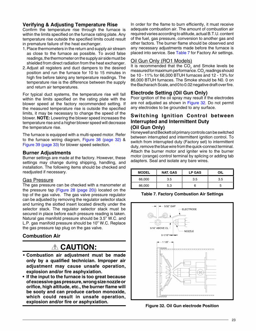
RG1OperatingInstructions(Direct Ignition Furnaces)Direct ignition furnaces do not have a pilot. Ignition is accomplished by a silicon carbide hot surface ignitor. A control module takes care of all timing functions. After lighting,thecontrolmoduleusestheignitorasaflamesensor,shuttingoffgasshouldtheflamegoout.Thereare no external relays or timing devices. Donottrytolightthisfurnacebyhand.Thecontrolmoduleisnotfieldserviceable.
1. Set the thermostat to the lowest setting.2. Turn off all electric power to the appliance.3. Remove the furnace door and turn off the gas valve:• Honeywell: push in and turn the gas control knob
clockwise to OFF. See Figure 30.• Robertshaw: push the gas control lever (Donotforce!)
to the OFF position. See Figure 31. 4. Wait ten (10) minutes to clear out any gas. If you smell
gas, STOP! and follow the Safety Information on page 21. If you do not smell gas, proceed to next step 5.
5. Set the thermostat MODE the On position.6. Turn the gas valve ON:• Honeywell: push in and turn gas control knob counter-
clockwise to On (Figure 30).• Robertshaw: push the gas control lever to the On position
(Figure 31). Donotforce!7. Replace the furnace door.8. Turn on all electric power to the appliance.9. Change the thermostat mode to HEAT and the
temperature selector to a desired temperature level. The igniter should light in approximately 75 seconds. If the appliance will not operate, see How to Shut Off Gas - Direct Ignition and call your service technician or gas supplier.
NOTE: In the event of any flashback or explosion,immediately shut off the furnace and call your service technician.
How to Shut Off Gas - Direct Ignition1. Set the thermostat to the lowest setting.2. Turn off all electric power to the appliance before
servicing unit.3. Set the furnace On-Off Switch to OFF.• Honeywell(Figure 30): Turn gas control knob clockwise
to OFF, Robertshaw (Figure 31): Push the gas control lever to OFF.
• Foroil,shutoffallvalves.4. Replace the furnace door.
RO1OperatingInstructions(Oil Gun Furnaces)If your furnace model number begins with RO1*, the furnace is equipped with an ignition device which automatically lights the burner. Donottrytolightthisfurnacemanually.
1. Open all valves in the oil line.2. Verify the fire door is closed.3. Set the furnace On-Off switch to On.4. Set the thermostat to the desired setting.
NOTE: RO1 oil gun furnaces may be converted to gas gun in the field by using the proper conversion kit listed in the Replacement Parts List.
How to Shut Off Gas - Oil & Gas Gun1. Set the thermostat to the lowest setting.2. Turn off all electric power to the appliance at the breaker
or fuse box.3. Set the thermostat MODE switch to OFF.4. Turn the gas valve OFF:
• Honeywell: push in and turn the gas control knob clockwise to the OFF position (Figure 30).
• Robertshaw: push the gas control lever to the OFF position (Figure 31).
5. Replace the furnace door.
Figure30.DirectIgnitionGasValve-Honeywell
GAS CONTROL KNOB Gas Control Lever
Figure 31. DirectIgnitionGasValve-Robertshaw
23
Inorderfortheflametoburnefficiently,itmustreceiveadequate combustion air. The amount of combustion air required varies according to altitude, actual B.T.U. content of the fuel, gas pressure, conversion to another gas and otherfactors.Theburnerflameshouldbeobservedandany necessary adjustments made before the furnace is placed into service. See Table 7 for Factory Air settings.
Oil Gun Only (RO1 Models)It is recommended that the CO2 and Smoke levels be measured for maximum performance. CO2 readings should be 10 - 11% for 66,000 BTUH furnaces and 12 - 13% for 86,000 BTUH furnaces. The Smoke should be N0. 0 on the Bacharach Scale, and 0 to 0.02 negative draft over fire.
ElectrodeSetting(OilGunOnly)Poor ignition of the oil spray may result if the electrodes are not adjusted as shown in Figure 32. Do not permit any electrodes to be grounded to any surface.
Switching Ignition Control betweenInterruptedandIntermittentDuty(OilGunOnly)Honeywell and Beckett oil primary controls can be switched between interrupted and intermittent ignition control. To switch from interrupted duty (Factory set) to intermittent duty, remove the blue wire from the quick-connect terminal. Attach the burner motor and igniter wire to the burner motor (orange) control terminal by splicing or adding tab adapters. Seal and isolate any bare wires.
Verifying&AdjustingTemperatureRiseConfirm the temperature rise through the furnace is within the limits specified on the furnace rating plate. Any temperature rise outside the specified limits could result in premature failure of the heat exchanger.1. Place thermometers in the return and supply air stream
as close to the furnace as possible. To avoid false readings, the thermometer on the supply air side must be shielded from direct radiation from the heat exchanger.
2. Adjust all registers and duct dampers to the desired position and run the furnace for 10 to 15 minutes in high fire before taking any temperature readings. The temperature rise is the difference between the supply and return air temperatures.
For typical duct systems, the temperature rise will fall within the limits specified on the rating plate with the blower speed at the factory recommended setting. If the measured temperature rise is outside the specified limits, it may be necessary to change the speed of the blower. NOTE: Lowering the blower speed increases the temperature rise and a higher blower speed will decrease the temperature rise.
The furnace is equipped with a multi-speed motor. Refer to the furnace wiring diagram, Figure 38 (page 32) & Figure 39 (page 33) for blower speed selection.
Burner AdjustmentsBurner settings are made at the factory. However, these settings may change during shipping, handling, and installation. The following items should be checked and readjusted if necessary.
Gas PressureThe gas pressure can be checked with a manometer at the pressure tap (Figure 28 (page 20)) located on the top of the gas valve. The gas valve pressure regulator can be adjusted by removing the regulator selector stack and turning the slotted insert located directly under the selector stack. The regulator selector stack must be secured in place before each pressure reading is taken. Natural gas manifold pressure should be 3.5” W.C. and L.P. gas manifold pressure should be 10” W.C. Replace the gas pressure tap plug on the gas valve.
Combustion Air
CAutIOn:•Combustion air adjustment must be made
only by a qualified technician. Improper airadjustment may cause unsafe operation,explosionand/orfireasphyxiation.
• Iftheinputtothefurnaceistoogreatbecauseofexcessivegaspressure,wrongsizenozzleororifice,highaltitude,etc.,theburnerflamewillbesootyandcanproducecarbonmonoxide,which could result in unsafe operation,explosionand/orfireorasphyxiation.
Table 7
table 7. FactoryCombustionAirSettings
MODEL nAt. GAS LPGAS OIl
66,000 3.5 3.5 3.5
86,000 5.3 6 5
5/32” GAPELECTRODE
NOZZLE
0-1/16”
5/16” ABOVE CL
1 1/8”
Figure 32. OilGunelectrodePosition
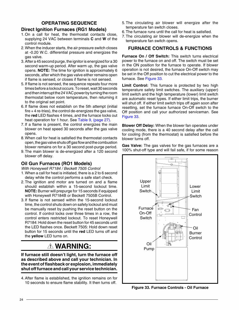
24
5. The circulating air blower will energize after the temperature fan switch closes.
6. The furnace runs until the call for heat is satisfied.7. The circulating air blower will de-energize when the
temperature fan switch opens.
FURNACECONTROLS&FUNCTIONS
FurnaceOn /OffSwitch: This switch turns electrical power to the furnace on and off. The switch must be set in the ON position for the furnace to operate. If blower operation is not desired, the furnace On-Off switch may be set in the Off position to cut the electrical power to the furnace. See Figure 33.
limit Control: This furnace is protected by two high temperature safety limit switches. The auxiliary (upper) limit switch and the high temperature (lower) limit switch are automatic reset types. If either limit trips, the burner will shut off. If either limit switch trips off again soon after resetting, set the furnace furnace On-Off switch to the Off position and call your authorized serviceman. See Figure 33.
BlowerOffDelay: When the blower fan operates under cooling mode, there is a 40 second delay after the call for cooling (from the thermostat) is satisfied before the blower turns off.
GasValve: The gas valves for the gas furnaces are a 100% shut-off type and will fail safe, if for some reason
OPERATINGSEQUENCEDirectIgnitionFurnaces(RG1Models)1. On a call for heat, the thermostat contacts close,
supplying 24 VAC between terminals C and W of the control module.
2. When the inducer starts, the air pressure switch closes at -0.20 W.C. differential pressure and energizes the gas valve.
3. After a 45 second purge, the ignitor is energized for a 30 second warm-up period. After warm up, the gas valve opens. NOTE:The time for ignition is approximately 6 seconds, after which the gas valve either remains open ifflameissensed,orclosesifflameisnotsensed.
5.Ifflameisnotsensed,thesequencerepeatsfourmoretimes before a lockout occurs. To reset, wait 30 seconds and then interrupt the 24 VAC power by turning the room thermostat below room temperature, then returning it to the original set point.
6.Ifflamedoesnotestablishonthe5thattempt(initialfire + 4 re-tries), the control de-energizes the gas valve, the redLEDflashes4times,andthefurnacelocksoutheat operation for 1 hour. See Table 9, (page 27).
7.Ifaflame ispresent, thecontrolenergizes themainblower on heat speed 30 seconds after the gas valve opens.
8. When call for heat is satisfied the thermostat contacts open,thegasvalveshutsoffgasflowandthecombustionblower remains on for a 30 second post-purge period.
9. The main blower is de-energized after a 120 second blower off delay.
OilGunFurnaces(RO1Models)With Honeywell R7184 / Beckett 7505 Control1. When a call for heat is initiated, there is a 2 to 6 second
delay while the control performs a safe start check.2.The ignition and motor are turned on and a flame
should establish within a 15-second lockout time. NOTE:Burner will prepurge for 15 seconds if equipped with Honeywell R7184B or Beckett 7505B Control.
3.If flame is not sensed within the 15-second lockouttime, the control shuts down on safety lockout and must be manually reset by pushing the reset button on the control. If control locks over three times in a row, the control enters restricted lockout. To reset Honeywell R7184: Hold down the reset button for 45 seconds until theLEDflashesonce.Beckett7505:Holddownresetbutton for 15 seconds until the red LED turns off and the yellow LED turns on.
WARnInG:Iffurnacestilldoesn’tlight,turnthefurnaceoffasdescribedaboveandcallyourtechnician.Intheeventofflashbackorexplosion,immediatelyshutofffurnaceandcallyourservicetechnician.
4.Afterflameisestablished,theignitionremainsonfor10secondstoensureflamestability.Itthenturnsoff.
FurnaceOn-Off Switch
OilPump
FanControl
Lower Limit
Switch
UpperLimit
Switch
OilBurnerControl
Figure 33. FurnaceControls-OilFurnace
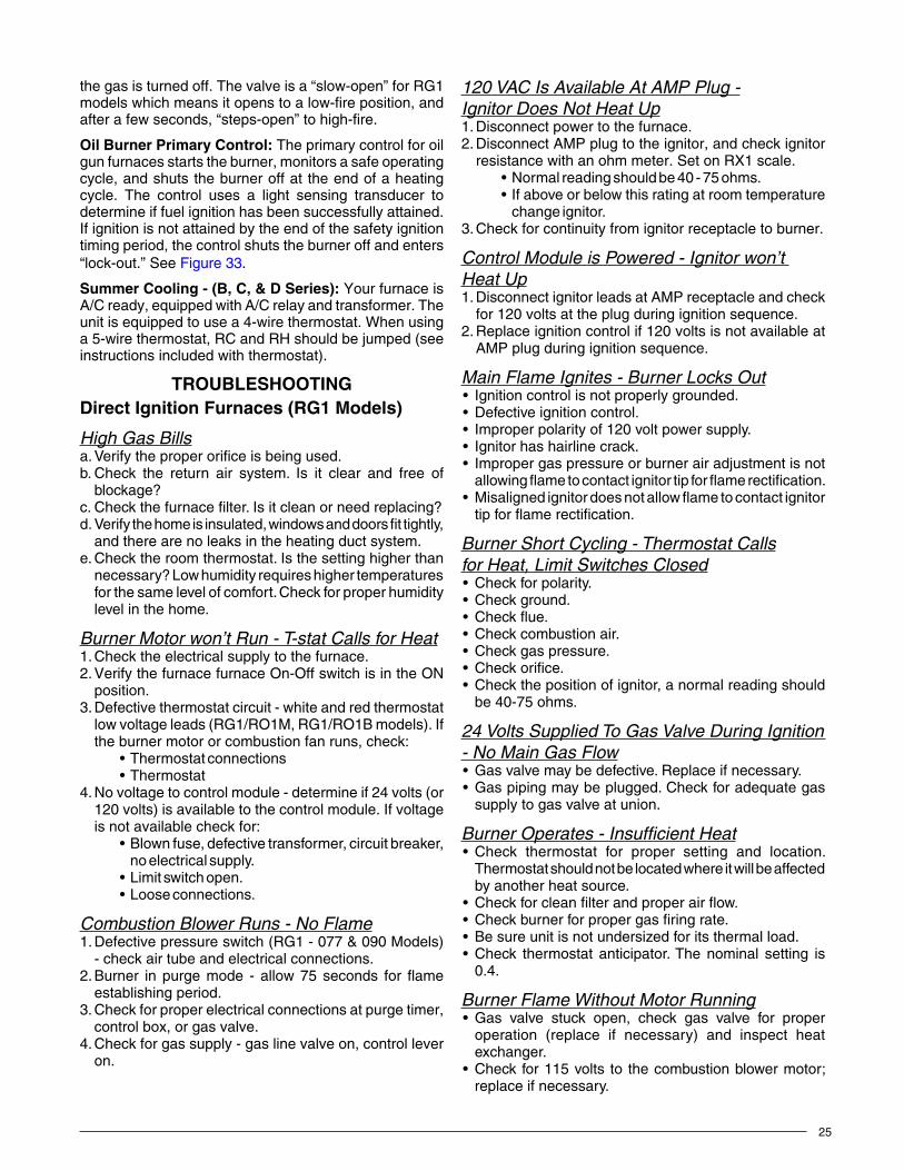
25
120 VAC Is Available At AMP Plug -Ignitor Does Not Heat Up1. Disconnect power to the furnace.2. Disconnect AMP plug to the ignitor, and check ignitor
resistancewithanohmmeter.SetonRX1scale.•Normalreadingshouldbe40-75ohms.•Ifaboveorbelowthisratingatroomtemperature
change ignitor.3. Check for continuity from ignitor receptacle to burner.
Control Module is Powered - Ignitor won’t Heat Up1. Disconnect ignitor leads at AMP receptacle and check
for 120 volts at the plug during ignition sequence.2. Replace ignition control if 120 volts is not available at
AMP plug during ignition sequence.
Main Flame Ignites - Burner Locks Out• Ignitioncontrolisnotproperlygrounded.• Defectiveignitioncontrol.• Improperpolarityof120voltpowersupply.• Ignitorhashairlinecrack.• Impropergaspressureorburnerairadjustmentisnot
allowingflametocontactignitortipforflamerectification.• Misalignedignitordoesnotallowflametocontactignitor
tipforflamerectification.
Burner Short Cycling - Thermostat Callsfor Heat, Limit Switches Closed• Checkforpolarity.• Checkground.• Checkflue.• Checkcombustionair.• Checkgaspressure.• Checkorifice.• Checkthepositionofignitor,anormalreadingshould
be 40-75 ohms.
24 Volts Supplied To Gas Valve During Ignition - No Main Gas Flow• Gasvalvemaybedefective.Replaceifnecessary.• Gaspipingmaybeplugged.Checkforadequategas
supply to gas valve at union.
Burner Operates - Insufficient Heat• Check thermostat for proper setting and location.
Thermostat should not be located where it will be affected by another heat source.
• Checkforcleanfilterandproperairflow.• Checkburnerforpropergasfiringrate.• Besureunitisnotundersizedforitsthermalload.• Check thermostat anticipator.The nominal setting is
0.4.
Burner Flame Without Motor Running• Gas valve stuck open, check gas valve for proper
operation (replace if necessary) and inspect heat exchanger.
• Checkfor115volts to thecombustionblowermotor;replace if necessary.
the gas is turned off. The valve is a “slow-open” for RG1 models which means it opens to a low-fire position, and after a few seconds, “steps-open” to high-fire.
OilBurnerPrimaryControl: The primary control for oil gun furnaces starts the burner, monitors a safe operating cycle, and shuts the burner off at the end of a heating cycle. The control uses a light sensing transducer to determine if fuel ignition has been successfully attained. If ignition is not attained by the end of the safety ignition timing period, the control shuts the burner off and enters “lock-out.” See Figure 33.
SummerCooling-(B,C,&DSeries): Your furnace is A/C ready, equipped with A/C relay and transformer. The unit is equipped to use a 4-wire thermostat. When using a 5-wire thermostat, RC and RH should be jumped (see instructions included with thermostat).
TROUBLESHOOTINGDirectIgnitionFurnaces(RG1Models)
High Gas Billsa. Verify the proper orifice is being used.b. Check the return air system. Is it clear and free of
blockage?c. Check the furnace filter. Is it clean or need replacing?d. Verify the home is insulated, windows and doors fit tightly,
and there are no leaks in the heating duct system.e. Check the room thermostat. Is the setting higher than
necessary? Low humidity requires higher temperatures for the same level of comfort. Check for proper humidity level in the home.
Burner Motor won’t Run - T-stat Calls for Heat1. Check the electrical supply to the furnace.2. Verify the furnace furnace On-Off switch is in the ON
position.3. Defective thermostat circuit - white and red thermostat
low voltage leads (RG1/RO1M, RG1/RO1B models). If the burner motor or combustion fan runs, check:
•Thermostatconnections•Thermostat
4. No voltage to control module - determine if 24 volts (or 120 volts) is available to the control module. If voltage is not available check for:
•Blownfuse,defectivetransformer,circuitbreaker,no electrical supply.
•Limitswitchopen.•Looseconnections.
Combustion Blower Runs - No Flame1. Defective pressure switch (RG1 - 077 & 090 Models)
- check air tube and electrical connections.2.Burner in purgemode - allow75 seconds for flame
establishing period.3. Check for proper electrical connections at purge timer,
control box, or gas valve.4. Check for gas supply - gas line valve on, control lever
on.

26
• Ifnopowertocombustionblowerthencheckwiringandcontrol module; replace if necessary.
Circulation Air Blower Will Not Operate Even Though The Burner Does Operate• CheckthermostatG connection.• Checkwiringtomotor.• Checkforadefectivemotor.
OilGun-HoneywellR7184orBeckett7505ControlsOnly-RO1Series.
Burner does not start with a call for heat• Checktheelectricalsupplytofurnace.• VerifythefurnacedoorswitchisintheOn position.• Check for line voltage (115VAC) at the oil primary
control.• CheckindicatorLEDwithburneroff,nocallforheat(no
flame).SeeTable 9, (page 27).- If green LED indicator is on, the cad cell is seeing
stray light or the cad cell of controller is defective.- If green LED indicator is off, go immediately to step
5.- IfLEDindicatorisflashing(redorgreenonBeckett
7505 control), refer to the next step 1 below - Reset primary control.
• Jumpert to t terminals on primary control.- If burner starts, check thermostat or limit wiring
connections.- If burner does not start, turn off power. Check all
wiring connections.- If burner does not start, replace primary control.
Burner starts & then locks out on safety with Honeywell R7184 LED indicator flashing ½ second on, ½ second off. For Beckett 7505 control, the red LED will flash
1. Reset primary control: To reset the control from (soft) lockout, the button needs only to be pressed and released. If the R7184 control is in restricted mode, press and hold the button for 45 seconds - until the LED flashesonce.Ifthe7505controlisinrestrictedmode,press and hold the button in for 15 seconds until the red turns off and the yellow LED turns on.
NOTE: Restricted Lockout: If the control locks out three times in a row without a complete heat cycle between attempts, the lockout becomes a restricted (hard) lockout.
2.If the LED indicator stops flashing and the ignitionremains off, the primary control could be defective. If line voltage is present at the igniter terminals, and there is no ignition, the igniter is likely defective and needs to be replaced.
3.Ifthestopsflashing,burnerturnson,butthecontrollocks out again, check the cad cell. If the cad cell is operational, replace the primary control.
4.If the LED continues to flash at the interval listedabove, verify that the control is not in restricted mode. If in restricted mode, reset it. If not in restricted mode, replace the control.
5. If the (LED indicator for R7184 control; green LED for 7505control)staysoffwhiletheflameison,checkthecadcellsightingforviewoftheflame.
6. If the burner locks out, check the cad cell resistance. See Table 8.
7. If the burner stays running, the system is operational.8. If the (LED indicator for R7184 control; green LED for
7505 control) is off, check the cad cell assembly after disconnecting the line voltage.
Burner will not start and the LED indicatoris flashing at 2 seconds on, 2 seconds offfor R7184 (or green LED is flashing for 7505)
• Holdtheresetbuttondownfor1-2seconds.IfLEDindicatorcontinuestoflash,waitfor60-70seconds.Ifitstillcontinuestoflash,replacetheprimarycontrol.
• Honeywell R7184 control: To check cad cell resistance, press and release the button during the run mode, with theigniteroff.TheLEDwillflashtoindicatethecadcellresistance. For proper burner operation, it is important that the cad cell resistance is under 1600 Ohms. For cad cell resistance, see Table 8.
• Beckett 7505 control: To check cad cell resistance, unplug the cad cell leads (yellow wires) from the control. Measure the resistance with a meter in the conventional way (when a flame is present). For proper burneroperation, it is important that the cad cell resistance is under 1,600 Ohms.
Table 8
table 8. CadCellResistancewhen sensing flame
LEDFLASHES(OHMS) CADCELLRESISTANCE
1 0-400
2 400-800
3 800-1600
4 >1600
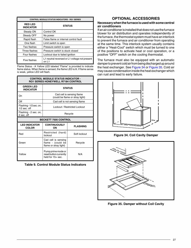
27
OPTIONALACCESSORIESNecessarywhenthefurnaceisusedwithsomecentralair conditionersIf an air conditioner is installed that does not use the furnace blower for air distribution and operates independently of the furnace, the thermostat system must have an interlock to prevent the furnace and air conditioner from operating at the same time. This interlock system usually contains either a “Heat-Cool” switch which must be turned to one of the positions to activate heat or cool operation, or a positive “OFF” switch on the cooling thermostat.
The furnace must also be equipped with an automatic damper to prevent cold air from being discharged up around the heat exchanger. See Figure 34 or Figure 35. Cold air may cause condensation inside the heat exchanger which can rust and lead to early failure.
Figure 34. CoilCavityDamper
Table 9CONTROLMODULESTATUSINDICATORS-RG1SERIES
REDLEDInDICAtOR
StAtuS
Steady ON ControlOK
Steady OFF No power
Rapidflash Falseflameorinternalcontrolfault
Oneflash Limit switch is open
Twoflashes Pressure switch is open
Threeflashes Pressure switch is stuck closed
Fourflashes Lockout due to failed ignition
Fiveflashes L1 neutral reversed or L1 voltage not present on L1
Flame Status - A Yellow LED labeled “Flame” is provided to indicate flamestatus.Whenflameissensed,theflameLEDislit.Ifflamesenseisweak,yellowLEDwillflash.
CONTROLMODULESTATUSINDICATOR-RO1SERIESHONEYWELLR7184CONTROL
GREENLEDInDICAtOR
StAtuS
On Cadcellissensingflame(couldbeflameorstraylight)
Off Cadcellisnotsensingflame
Flashing - 1/2 sec. on, 1/2 sec. off Lockout / Restricted Lockout
Flashing - 2 sec. on, 2 sec. off Recycle
BECKETT7505CONTROL
LEDINDICATORCOlOR
CONTINUOUSLYOn
FLASHING
Red Restricted (hard) lockout Soft lockout
GreenCad cell is sensing flame - (could be flameorstraylight)
Recycle
YellowPump prime mode or reset button currently held for 15+ sec.
N/A
table 9. ControlModuleStatusIndicators
Figure 35. DamperwithoutCoilCavity
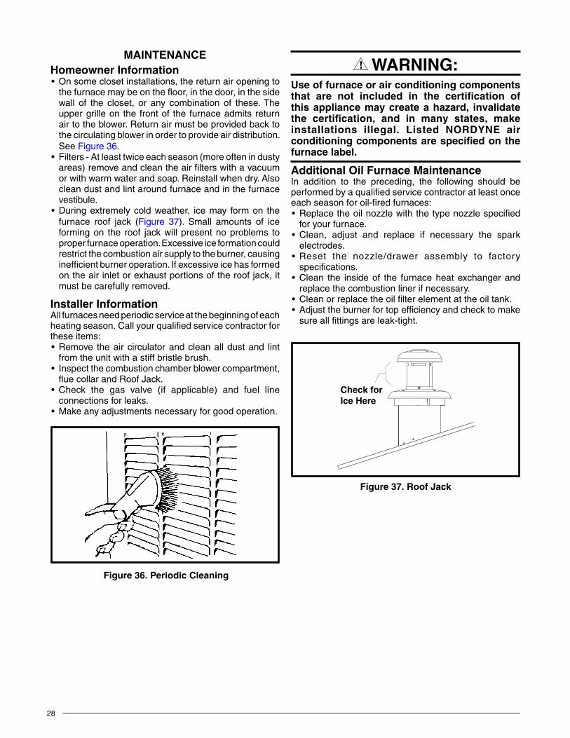
28
MAINTENANCEHomeownerInformation• Onsomeclosetinstallations,thereturnairopeningto
thefurnacemaybeonthefloor,inthedoor,inthesidewall of the closet, or any combination of these. The upper grille on the front of the furnace admits return air to the blower. Return air must be provided back to the circulating blower in order to provide air distribution. See Figure 36.
• Filters-Atleasttwiceeachseason(moreoftenindustyareas) remove and clean the air filters with a vacuum or with warm water and soap. Reinstall when dry. Also clean dust and lint around furnace and in the furnace vestibule.
• Duringextremelycoldweather, icemay formon thefurnace roof jack (Figure 37). Small amounts of ice forming on the roof jack will present no problems to proper furnace operation. Excessive ice formation could restrict the combustion air supply to the burner, causing inefficient burner operation. If excessive ice has formed on the air inlet or exhaust portions of the roof jack, it must be carefully removed.
InstallerInformationAll furnaces need periodic service at the beginning of each heating season. Call your qualified service contractor for these items:• Remove theaircirculatorandcleanalldustand lint
from the unit with a stiff bristle brush.• Inspectthecombustionchamberblowercompartment,
fluecollarandRoofJack.• Check the gas valve (if applicable) and fuel line
connections for leaks.• Makeanyadjustmentsnecessaryforgoodoperation.
WARnInG:Useoffurnaceorairconditioningcomponentsthat are not included in the certification ofthisappliancemaycreateahazard, invalidatethe certification, and in many states, makeinstallations illegal. Listed NORDYNE airconditioningcomponentsarespecifiedonthefurnacelabel.
AdditionalOilFurnaceMaintenanceIn addition to the preceding, the following should be performed by a qualified service contractor at least once each season for oil-fired furnaces:• Replacetheoilnozzlewiththetypenozzlespecified
for your furnace.• Clean, adjust and replace if necessary the spark
electrodes.• Reset the nozzle/drawer assembly to factory
specifications.• Clean the insideof the furnaceheatexchangerand
replace the combustion liner if necessary.• Cleanorreplacetheoilfilterelementattheoiltank.• Adjusttheburnerfortopefficiencyandchecktomake
sure all fittings are leak-tight.
Figure 36. PeriodicCleaning
Figure 37. RoofJack
Check forIce Here
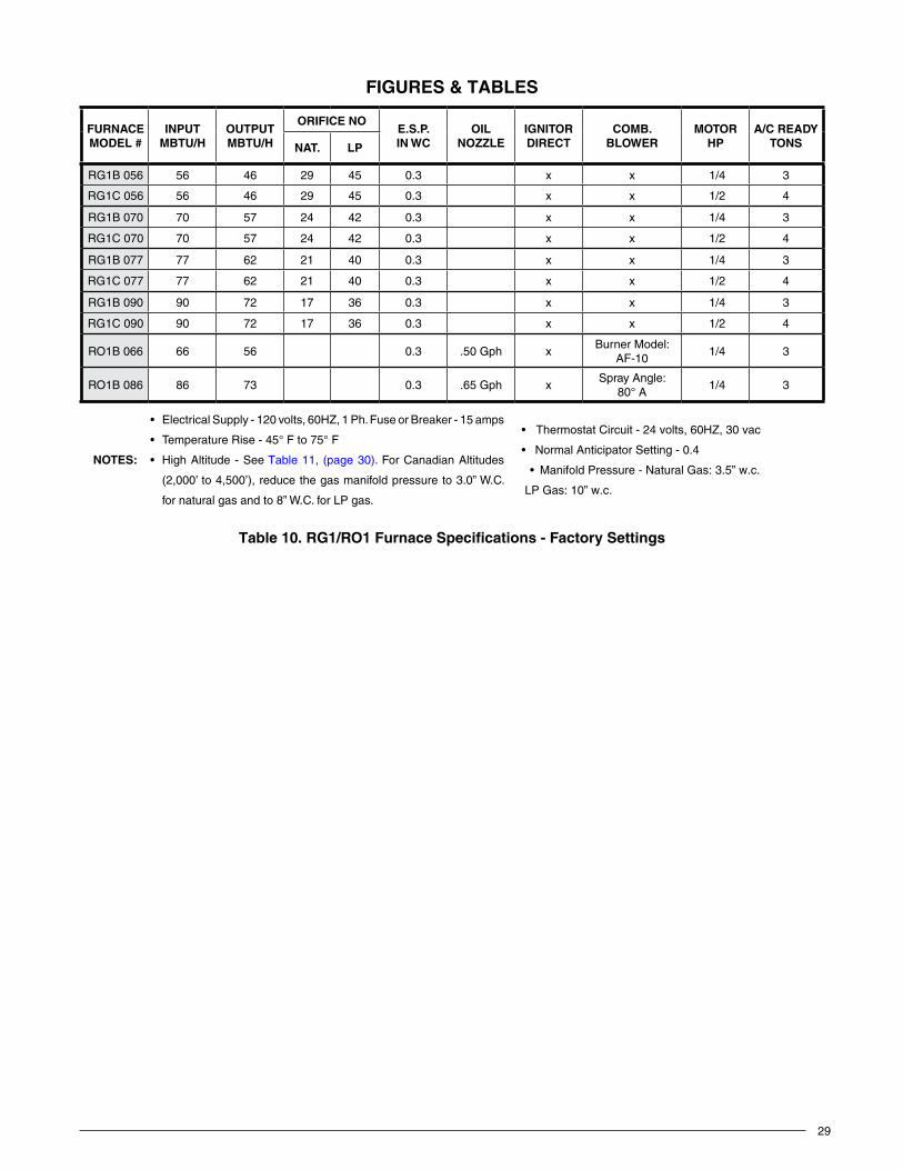
29
Table 10
Table10.RG1/RO1FurnaceSpecifications-FactorySettings
FURNACEMODEL#
INPUTMBTU/H
OUTPUTMBTU/H
ORIFICENOE.S.P.In WC
OIlNOZZLE
IGnItORDIRECT
COMB.BLOWER
MOTORHP
A/CREADYtOnSnAt. LP
RG1B 056 56 46 29 45 0.3 x x 1/4 3
RG1C 056 56 46 29 45 0.3 x x 1/2 4
RG1B 070 70 57 24 42 0.3 x x 1/4 3
RG1C 070 70 57 24 42 0.3 x x 1/2 4
RG1B 077 77 62 21 40 0.3 x x 1/4 3
RG1C 077 77 62 21 40 0.3 x x 1/2 4
RG1B 090 90 72 17 36 0.3 x x 1/4 3
RG1C 090 90 72 17 36 0.3 x x 1/2 4
RO1B 066 66 56 0.3 .50 Gph xBurner Model:
AF-10 1/4 3
RO1B 086 86 73 0.3 .65 Gph xSpray Angle:
80° A 1/4 3
NOTES:
• ElectricalSupply-120volts,60HZ,1Ph.FuseorBreaker-15amps
• TemperatureRise-45°Fto75°F
• HighAltitude-SeeTable 11, (page 30). For Canadian Altitudes
(2,000’to4,500’),reducethegasmanifoldpressureto3.0”W.C.
for natural gas and to 8” W.C. for LP gas.
• ThermostatCircuit-24volts,60HZ,30vac
• NormalAnticipatorSetting-0.4
• ManifoldPressure-Natural Gas: 3.5” w.c.
LP Gas: 10” w.c.
FIGURES&TABLES
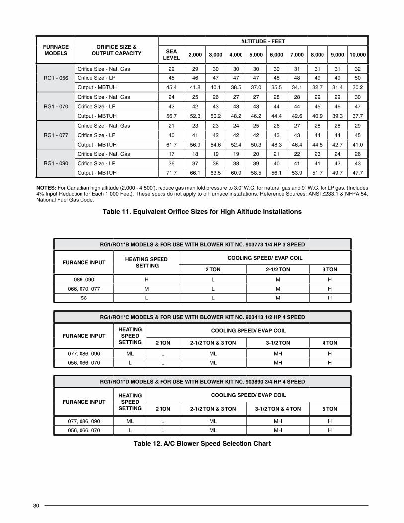
30
Table 12RG1/RO1*BMODELS&FORUSEWITHBLOWERKITNO.9037731/4HP3SPEED
FURANCEINPUTHEATINGSPEED
SETTINGCOOLINGSPEED/EVAPCOIL
2 tOn 2-1/2TON 3 tOn
086, 090 H L M H
066, 070, 077 M L M H
56 L L M H
RG1/RO1*CMODELS&FORUSEWITHBLOWERKITNO.9034131/2HP4SPEED
FURANCEINPUTHEATING SPEED
SETTING
COOLINGSPEED/EVAPCOIL
2 tOn 2-1/2TON&3TON 3-1/2TON 4 tOn
077, 086, 090 ML L ML MH H
056, 066, 070 L L ML MH H
RG1/RO1*DMODELS&FORUSEWITHBLOWERKITNO.9038903/4HP4SPEED
FURANCEINPUTHEATING SPEED
SETTING
COOLINGSPEED/EVAPCOIL
2 tOn 2-1/2TON&3TON 3-1/2TON&4TON 5 tOn
077, 086, 090 ML L ML MH H
056, 066, 070 L L ML MH H
table 12. A/CBlowerSpeedSelectionChart
Table 11
table 11. EquivalentOrificeSizesforHighAltitudeInstallations
FURNACEMODELS
ORIFICESIZE&OUTPUTCAPACITY
ALTITUDE-FEET
SEALEVEL
2,000 3,000 4,000 5,000 6,000 7,000 8,000 9,000 10,000
RG1 - 056
Orifice Size - Nat. Gas 29 29 30 30 30 30 31 31 31 32
Orifice Size - LP 45 46 47 47 47 48 48 49 49 50
Output - MBTUH 45.4 41.8 40.1 38.5 37.0 35.5 34.1 32.7 31.4 30.2
RG1 - 070
Orifice Size - Nat. Gas 24 25 26 27 27 28 28 29 29 30
Orifice Size - LP 42 42 43 43 43 44 44 45 46 47
Output - MBTUH 56.7 52.3 50.2 48.2 46.2 44.4 42.6 40.9 39.3 37.7
RG1 - 077
Orifice Size - Nat. Gas 21 23 23 24 25 26 27 28 28 29
Orifice Size - LP 40 41 42 42 42 43 43 44 44 45
Output - MBTUH 61.7 56.9 54.6 52.4 50.3 48.3 46.4 44.5 42.7 41.0
RG1 - 090
Orifice Size - Nat. Gas 17 18 19 19 20 21 22 23 24 26
Orifice Size - LP 36 37 38 38 39 40 41 41 42 43
Output - MBTUH 71.7 66.1 63.5 60.9 58.5 56.1 53.9 51.7 49.7 47.7
NOTES:ForCanadianhighaltitude(2,000-4,500’),reducegasmanifoldpressureto3.0”W.C.fornaturalgasand9”W.C.forLPgas.(Includes4% Input Reduction for Each 1,000 Feet). These specs do not apply to oil furnace installations. Reference Sources: ANSI Z233.1 & NFPA 54, National Fuel Gas Code.
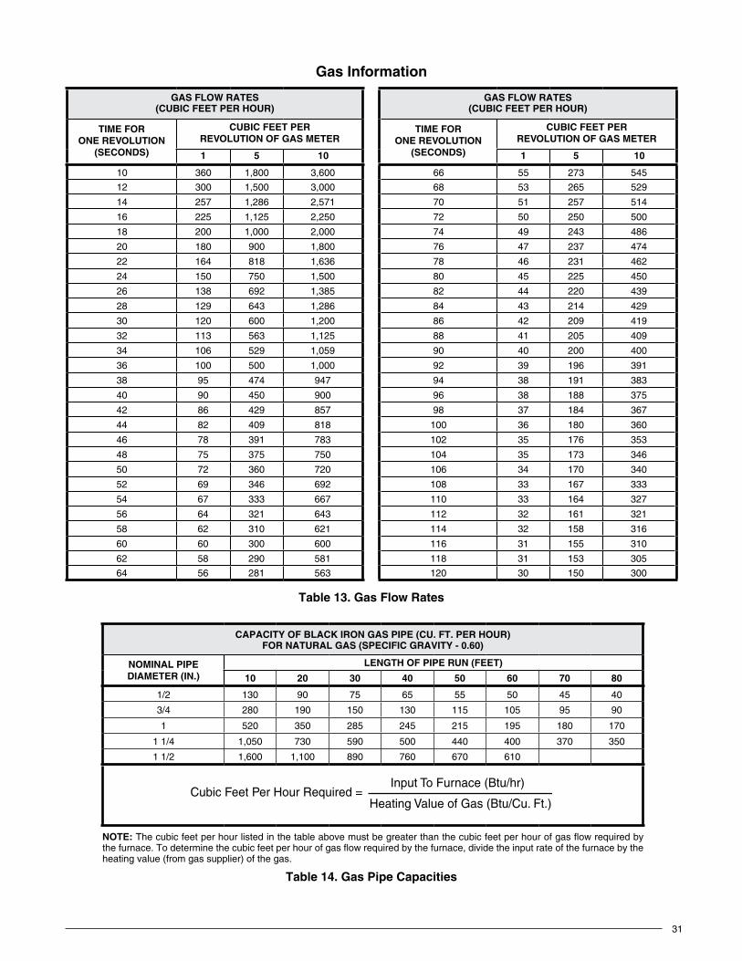
31
GasInformation
Table 13GASFLOWRATES(CUBICFEETPERHOUR)
TIMEFORONEREVOLUTION
(SECONDS)
CUBICFEETPERREVOLUTIONOFGASMETER
1 5 10
10 360 1,800 3,600
12 300 1,500 3,000
14 257 1,286 2,571
16 225 1,125 2,250
18 200 1,000 2,000
20 180 900 1,800
22 164 818 1,636
24 150 750 1,500
26 138 692 1,385
28 129 643 1,286
30 120 600 1,200
32 113 563 1,125
34 106 529 1,059
36 100 500 1,000
38 95 474 947
40 90 450 900
42 86 429 857
44 82 409 818
46 78 391 783
48 75 375 750
50 72 360 720
52 69 346 692
54 67 333 667
56 64 321 643
58 62 310 621
60 60 300 600
62 58 290 581
64 56 281 563
table 13. Gas Flow Rates
GASFLOWRATES(CUBICFEETPERHOUR)
TIMEFORONEREVOLUTION
(SECONDS)
CUBICFEETPERREVOLUTIONOFGASMETER
1 5 10
66 55 273 545
68 53 265 529
70 51 257 514
72 50 250 500
74 49 243 486
76 47 237 474
78 46 231 462
80 45 225 450
82 44 220 439
84 43 214 429
86 42 209 419
88 41 205 409
90 40 200 400
92 39 196 391
94 38 191 383
96 38 188 375
98 37 184 367
100 36 180 360
102 35 176 353
104 35 173 346
106 34 170 340
108 33 167 333
110 33 164 327
112 32 161 321
114 32 158 316
116 31 155 310
118 31 153 305
120 30 150 300
Table 14CAPACITYOFBLACKIRONGASPIPE(CU.FT.PERHOUR)FORNATURALGAS(SPECIFICGRAVITY-0.60)
NOMINALPIPEDIAMETER(IN.)
LENGTHOFPIPERUN(FEET)
10 20 30 40 50 60 70 80
1/2 130 90 75 65 55 50 45 40
3/4 280 190 150 130 115 105 95 90
1 520 350 285 245 215 195 180 170
1 1/4 1,050 730 590 500 440 400 370 350
1 1/2 1,600 1,100 890 760 670 610
NOTE:Thecubicfeetperhourlistedinthetableabovemustbegreaterthanthecubicfeetperhourofgasflowrequiredbythefurnace.Todeterminethecubicfeetperhourofgasflowrequiredbythefurnace,dividetheinputrateofthefurnacebytheheating value (from gas supplier) of the gas.
Cubic Feet Per Hour Required =Input To Furnace (Btu/hr)
Heating Value of Gas (Btu/Cu. Ft.)
table 14. GasPipeCapacities
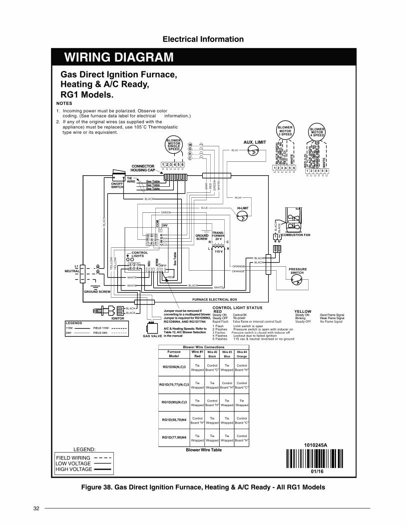
32
Figure 38. GasDirectIgnitionFurnace,Heating&A/CReady-AllRG1Models
See
Tabl
e
BLOWERMOTORSINGLESPEED
ON/OFFSWITCH
CRGW
GAS VALVE
HI-LIMIT
AUX. LIMIT
TRANS-FORMER
PRESSURESWITCH
654321654321
COMBUSTION FAN
L N
CR24 V
115 V
21
145
263
123
456
789
IGNITOR
L1NEUTRAL
GROUND SCREW
FURNACE ELECTRICAL BOX
24V
TIEWIRE
See Table
CONNECTORHOUSING CAP
GROUNDSCREW
CONTROL LIGHT STATUSWOLLEYDER
langiS emalF dooGNO ydaetSKO lortnoCNO ydaetSlangiS emalF kaeWgniknilBrewop oNFFO ydaetS
1 Flash Limit switch is open2 Flashes Pressure switch is open with inducer on
4 Flashes Lockout due to failed ignition5 Flashes 115 vac & neutral reversed or no ground
CONTROLLIGHTS
Jumper must be removed if converting to a multispeed blower.Jumper is required for RG1D90N3,RG1D90N4, AND RG1D77N4
A/C & Heating Speeds: Refer to Table 12, A/C Blower Selectionin the manual
RED
(LO
)B
LAC
K (H
IGH
)BL
UE (M
ED. H
I)OR
ANGE
(MED
. LO)
WH
ITE
RED
(LO
)
BLA
CK
(HIG
H)
BLUE
(MED
. HI)
WH
ITE
654321
LEGENDS115V: FIELD 115V:
24V: FIELD 24V:
BLOWERMOTOR4 SPEED
NOTES1. Incoming power must be polarized. Observe color
coding. (See furnace data label for electrical information.)2. If any of the original wires (as supplied with the
appliance) must be replaced, use 105˚C Thermoplastic type wire or its equivalent.
SUPPLIEDBY INSTALLER
C W
G R
COM
MOTOR
BLOWER
3 SPEEDMOTOR
See TableSee Table
Gas Direct Ignition Furnace,Heating & A/C Ready, RG1 Models.
1010245ABlower Wire Table
Blower Wire ConnectionsFurnace Wire #1 Wire #2 Wire #3 Wire #4Model Red Black Blue Orange
RG1D56(N,C)3 Tie Control Tie ControlWrapped Board "C" Wrapped Board "H"
RG1D(70,77)(N,C)3 Tie Tie Control ControlWrapped Wrapped Board "H" Board "C"
RG1D(90)(N,C)3 Tie Control Tie TieWrapped Board "H" Wrapped Wrapped
RG1D(56,70)N4 Control Tie Tie ControlBoard "H" Wrapped Wrapped Board "C"
RG1D(77,90)N4 Tie Tie Tie ControlWrapped Wrapped Wrapped Board "H"
01/16
WIRING DIAGRAM
FIELD WIRING
LEGEND:
LOW VOLTAGEHIGH VOLTAGE
NEU
XFRM
L1 H C
BLACK
BLACK
BLACK
WHITE
WHITEWHITE
ORANGE
ORANGE
BLACK
BLACK
BLA
CK
RE
D
GR
EE
N
WH
ITE
YE
LLO
WY
ELLO
W
BLA
CK
BLA
CK
GREEN
BLUE
BLUE
BLUE
GR
AY
BLACK
RED
ElectricalInformation

33
Figure 39. GasandOilFurnaces,A/CReady-RO1(066,086)Models
152
A/CBLOWERRELAY
364
FANSWITCH
HI-LIMIT
AUX. LIMIT
TRANSFORMER
L1 N
CR 24 V
115 V
GROUNDSCREW FURNACE
ELECTRICAL BOX
TIE WIRE
3A F
USE
654321RE
D (L
O)
BLA
CK (H
IGH
)BL
UE
(MED
. HI)
WH
ITE
4 SPEEDBLOWERMOTOR
CR
GW
ON/OFFSWITCH
CONNECTORHOUSING CAP
SUPPLIEDBY INSTALLER
654321
RED
(LO
)BL
UE (M
EDHI
)
BLA
CK (H
I)
WH
ITE
3 SPEEDBLOWERMOTOR
ORAN
GE (M
ED LO
)
C R WRECEPTACLE
BUSHING
NEUTRALL1
TO BURNER CONTROL
WHITE
RED
(SEE
NO
TE 3
)
WHITE
BLUE
WHITE
BLUE
GRAY
BLACK
BLACKORANGE
WHITE
RED
GRA
YRE
DG
REEN
WH
ITE
GRA
YRE
D
GRE
EN
BLA
CK
BLACK
GREEN
GRAY
BLUEBLACK
ORANGE
RED
BLA
CK
LINE CORD
TT
CAD
CELL
FROM 'R' WIRE (RED)
FROM 'W' WIRE (BLUE)
CAD
CELL
R7184BPRIMARYCONTROL
OIL GUN BURNER
NL1
BURNER ELECTRICAL BOX
GAS VALVE
GREEN
BLUEBLUE
BLACK
WHITE
RED
REDRED
BLACK
GROUND SCREW
BLACKBLACK
REDRED
BLACKBLACK
GRAY
TERMINAL HOUSING
BUSHING
LINE CORD
TERMINAL
BU
SHIN
G
BUSHING
BUSHING
BUSHING
WC
IGNITER
FROM "C"WIRE (GRAY)
BLA
CKBL
ACK
FROM "W"WIRE (BLUE)
GAS GUN BURNER
GV
PSOFSGC
INDL 1HSI
HSIGL 2W
PSIFSI
CONTROLMODULE
IGNITERL2
MOTORL2
L2L1
VALVEL2
120 Volt zH 06 / esahP elgniSseireS ecanruF 1OR
10102460
11/15
BLUE W/WHITE STRIPEWHITE
ORANGEWHITE
BLACK
BLACK W/WHITE STRIPE
VIOLETWHITE
IGNITIONMODULE
BURNERMOTOR
VALVE
NOTES:1. Incoming power must be polarized. Observe color coding. (See furnace data label for electrical information.)2. If any of the original wires (as supplied with the appliance) must be replaced, use 105˚C Thermoplastic type wire or its equivalent.3. On models M1(B,S)A and M1/M5(B,S)086 jumper wire is installed. On all other models, cooling speed is connected to black wire.
4. A/C Heating Speeds: Refer to Table 12, A/C Blower Selection5. If any of the original wire supplied with the appliance is replaced, use 105˚C wire or equivalent.6. Use copper conductors only.7. Flash Codes: Refer to Table 9, Control Module Status Indicators.
YELLOW
YELLOW
7505BOR
WIRING DIAGRAM
FIELD WIRING
LEGEND:
LOW VOLTAGEHIGH VOLTAGE

34

35
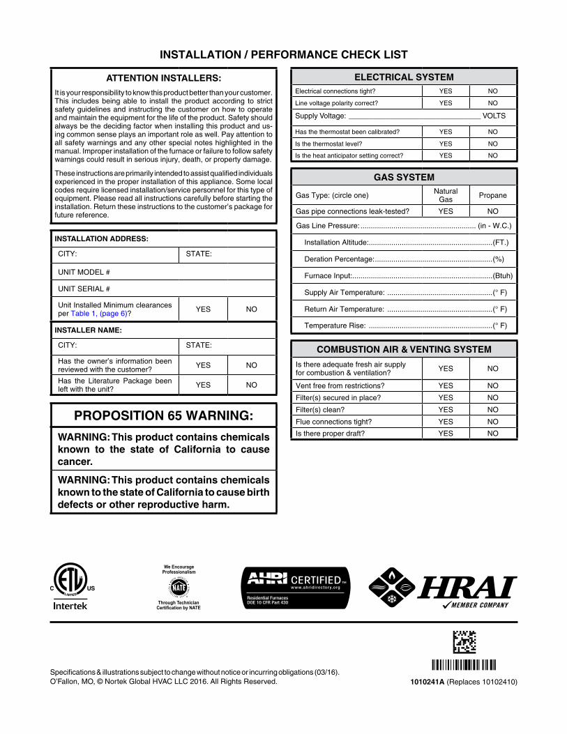
1010241A(Replaces 10102410)
INSTALLATION/PERFORMANCECHECKLIST
PROPOSITION65WARNING:
WARNING:Thisproductcontainschemicalsknown to the state of California to causecancer.
WARNING:ThisproductcontainschemicalsknowntothestateofCaliforniatocausebirthdefectsorotherreproductiveharm.
Specifications & illustrations subject to change without notice or incurring obligations (03/16).O’Fallon,MO,©NortekGlobalHVACLLC2016.AllRightsReserved.
ELECTRICALSYSTEMElectrical connections tight? YES NO
Line voltage polarity correct? YES NO
Supply Voltage: ________________________________ VOLTS
Has the thermostat been calibrated? YES NO
Is the thermostat level? YES NO
Is the heat anticipator setting correct? YES NO
GASSYSTEM
Gas Type: (circle one) NaturalGas Propane
Gas pipe connections leak-tested? YES NO
Gas Line Pressure: ........................................................ (in - W.C.)
Installation Altitude:............................................................(FT.)
Deration Percentage: .........................................................(%)
Furnace Input:....................................................................(Btuh)
Supply Air Temperature: ...................................................(° F)
Return Air Temperature: ...................................................(° F)
Temperature Rise: ............................................................(° F)
COMBUSTIONAIR&VENTINGSYSTEM
Is there adequate fresh air supplyfor combustion & ventilation? YES NO
Vent free from restrictions? YES NO
Filter(s) secured in place? YES NO
Filter(s) clean? YES NO
Flue connections tight? YES NO
Is there proper draft? YES NO
ATTENTIONINSTALLERS:
It is your responsibility to know this product better than your customer. This includes being able to install the product according to strict safety guidelines and instructing the customer on how to operate and maintain the equipment for the life of the product. Safety should always be the deciding factor when installing this product and us-ing common sense plays an important role as well. Pay attention to all safety warnings and any other special notes highlighted in the manual. Improper installation of the furnace or failure to follow safety warnings could result in serious injury, death, or property damage.
These instructions are primarily intended to assist qualified individuals experienced in the proper installation of this appliance. Some local codes require licensed installation/service personnel for this type of equipment. Please read all instructions carefully before starting the installation.Returntheseinstructionstothecustomer’spackageforfuture reference.
INSTALLATIONADDRESS:
CITY: STATE:
UNIT MODEL #
UNIT SERIAL #
Unit Installed Minimum clearances per Table 1, (page 6)? YES NO
INSTALLERNAME:
CITY: STATE:
Has theowner’s informationbeenreviewed with the customer? YES NO
Has the Literature Package been left with the unit? YES NO
Recommended