1
REVIEW OF PITTING CORROSION FATIGUE MODELS
Prof. D.W. Hoeppner1
Dr. V. Chandrasekaran2
Ms. A.M.H. Taylor3
The combined effect of corrosion and cyclic loading have beenshown to produce cracks from corrosion pits and pits havefrequently been the source of cracks on aircraft componentsoperating in fleets. Once the pit or group of pits form, the rate ofpit growth is dependent mainly on the material, environmentalconditions, and type and state of stress. Therefore, to estimate thetotal corrosion fatigue life of a component, it is of great importanceto develop realistic models to establish the component life in thesesituations and to formulate methods by which designers andoperators know likely sources of pitting early in the design andfleet operation. Therefore, to understand this phenomena, somemodels based on pitting corrosion fatigue (PCF) mechanismsand understanding have been proposed in the past and new onesare emerging.
It is important to note that both pitting theory and crack growththeory have been used in pitting corrosion fatigue modeldevelopment. The first known conceptual (notional) model waspresented in 1971 and subsequently the pit growth rate theoryproposed by Godard was combined with fatigue crack growthconcepts. Following this basic idea, a few models have beenproposed.
This paper presents some examples of critical pitting corrosionfatigue situations in aircraft, discusses the framework of the PCFmodels to date, presents some applications of the models, anddiscusses current work underway. Additionally, somerecommendations are made related to future work needed toenhance structural integrity and degradation of aircraft from thisfailure mechanism.
INTRODUCTION
The phases of life of a structure may be classified as follows (1):
1 Professor and Director, Quality and Integrity Design Engineering Center (QIDEC), MechanicalEngineering Department, University of Utah, Salt Lake City, Utah 84112.2 Research Assistant Professor, Mechanical Engineering Department, University of Utah, Salt Lake City,Utah 84112.3 Research Engineer, Mechanical Engineering Department, University of Utah, Salt Lake City, Utah 84112.
2
• Nucleation or formation of damage by a specific, physical or corrosion damageprocess interacting with the fatigue process if appropriate. Corrosion and otherprocesses may act alone to create the damage. a transition from the nucleation stageto the next phase must occur. Phase L1.
• Microstructurally dominated crack linkup and propagation (“short” or “small” crackregime). Phase L2.
• Crack propagation in the regime where either LEFM, EPFM, or FPFM may beapplied both for analysis and material characterization (the “long” crack regime).Phase L3.
• Final instability. Phase L4.
Thus, the total life (LT) of a structure is LT = L1+L2+L3+L4. Figure 1 presents adepiction of the degradation process. The regions shown, e.g. 1, 2, 3, and 4, illustrate theportion of life, on the abscissa, and the corresponding growth in discontinuity size plottedschematically on the ordinate. This paper concentrates on the phases L1 and L2. That is,the corrosion process that results in the generation of a specific form of corrosiongenerating a specific form of discontinuity that is not necessarily a crack likediscontinuity, and the development of short cracks and their propagation. Therequirement of the community to come up with design methods to deal with corrosion orother degradation, fatigue, creep, and wear, is essential and some of the elements aredepicted in Figure 2. This figure illustrates that most of the quantitative methods thathave been developed used the concepts of mechanics of materials with an incorporationof fracture mechanics (2).
EFFECTS OF CORROSION ON STRUCTURAL INTEGRITY OF AIRCRAFT
The issue of the effects of corrosion on structural integrity of aircraft has been aquestion of concern for some time (3-38). The potential effects are many and they can becategorized as follows. In the discussion below the use of the terms global and localrefers to the likely extent of the corrosion on the surface of a component. Global meansthe corrosion would be found on much of the component whereas local means thecorrosion may be localized to only small, local areas.
1) Reduce the section with a concomitant increase in stress. Global or local.2) Produce a stress concentration. Local.3) Nucleate cracks. Local, possibly global. Source of Multiple-site cracking.4) Produce corrosion debris. This may result in surface pillowing by various means,
which may significantly change the stress state and structural behavior. Local andglobal.
5) Create a situation that causes the surfaces to malfunction. Local and global.6) Cause environmentally assisted crack growth (EACG) under cyclic (Corrosion
fatigue) or sustained loading (SCC) conditions. Local.7) Create a damage state that is missed in inspection when the inspection plan was
not developed for corrosion or when corrosion is missed. Local and global.8) Change the structurally significant item due to the creation of a damage state not
envisioned in the structural damage analysis or fatigue and strength analysis. If

3
the SSI is specified, for example, by location of maximum stress or strain, thenthe corrosion may cause another area(s) to become significant. Local or global.
9) Create an embrittlement condition in the material that subsequently affectsbehavior. Local or Global.
10) Create a general aesthetic change from corrosion that creates maintenance to bedone and does damage to the structure. Local or global.
11) Corrosion maintenance does not eliminate all the corrosion damage and crackingor the repair is specified improperly or executed improperly thus creating adamage state not accounted for in the design. Local or global.
12) Generate a damage state that alters either the durability phase of life or thedamage tolerant assessment of the structure or both.
13) Create a widespread corrosion damage (WCD) state or a state of corrosion thatimpacts the occurrence of widespread fatigue damage (WFD) and its concomitanteffects. (See references 3, 5, 6, 15, 17, 28, 29, 30, 34, 35, 36, 37, 38 for moreinformation).
The question of whether corrosion, corrosion fatigue and stress corrosion cracking aresafety concerns or just maintenance/economic concerns has been a point of discussionrelated to aircraft structural integrity for over 30 years. Nonetheless, a great deal of theaircraft structural integrity community believes that corrosion related degradation is justan economic concern. It was with this situation in mind that Campbell and Lehay (14)and Wallace, Hoeppner and Kandachar (15) pursued the presentation of technical factsand knowledge to illustrate the potential for a safety issue as well as amaintenance/economic issue. Finally, Hoeppner et al (30) at the 1995 ICAF meeting inMelbourne, Australia reviewed failure data obtained from the USAF, USN, US Army,FAA, and the NTSB related to aircraft incidents and accidents in the USA between 1975-1994 to evaluate further the potential for corrosion and fretting related degradation to besignificant safety issues. Recently, several instances of pitting corrosion in aircraft andhelicopter components have been identified as critical safety issues as discussed in thefollowing section.
EXAMPLES OF PITTING CORROSION INCIDENTS
A survey was performed of incidents and accidents of aircraft and helicopterscaused by pitting corrosion, where an incident is any damage to the aircraft and/orinjuries to passengers and crew and an accident is loss of the aircraft and/or fatal injuriesto passengers and crew. Data were taken from the NTSB and FAA web-sites, whichinclude their databases of all aircraft incidents and accidents since 1983. It wasdetermined that of the 91 incidents and accidents found under corrosion, seven of thosegave the cause of failure as pitting corrosion.
Unfortunately, it has been found that there are problems in reporting the causes ofthe incidents and accidents in the NTSB and FAA in that the real cause of an incident oraccident is not reported properly and, therefore, does not show up in the database. Forexample, in reading through some of the incidents and accidents caused by corrosion, itwas found in the text that the real cause of failure was, more specifically, due to pittingcorrosion or exfoliation. But those words were not highlighted so that incident or

4
accident did not show up in a search of pitting corrosion or exfoliation. This makes thevalidity of numbers of incidents and accidents caused by pitting corrosion questionabledue to the fact that additional incidents and accidents may be listed under different causesand/or more general causes. Also included in the survey were the three Embraer 120incidents involving propeller blades, the Aero Commander 680 lower spar cap, and the F-18 trailing edge flap failure. These civilian and military incidents and accidents were alldue to pitting corrosion as shown in Table 1. When these examples are taken with thegeneral information cited in the previous references they clearly show that corrosionrelated degradation is a significant safety issue in the assurance of structural integrity ofaircraft.
Therefore, the potential regrettable occurrence of accidents from corrosion relatedcrack nucleation is a constant threat to aircraft safety. The following quote from therecent NATO RTO conference on fatigue in the presence of corrosion adds someunderstanding to the need for greater effort to understand the potential role of effects ofcorrosion on structural integrity.
“Some of the workshop papers discussed the significance of corrosion-fatigue as a safety issue or an economic issue. There is ample data tosupport the contention that it is definitely an economic issue. There is alsoample data to support the contention that it has not been a significantsafety problem. However, the problem is certainly a potential safetyconcern if maintenance does not perform their task diligently. In addition,management must continuously update established maintenance andinspection practices to address additional real-time degradation threatsfor aircraft operated well beyond their initial design certification life. Theeconomic issue alone is sufficient to motivate the support of research anddevelopment that can reduce the maintenance burden. This research willalso reduce the threat of catastrophic failure from the corrosion damage.”(Lincoln, J., Simpson, D., Introduction to Reference 38).
Another quote from a different reference also sheds further light on this issue (36-page 1-1).
“At the present time, structural life assessments, inspection requirements,and inspection intervals, are determined by Durability and DamageTolerance Assessments (DADTAs) using fracture mechanics crack growthtechniques in accordance with the Aircraft Structural Integrity Program(ASIP). These techniques do not normally consider the effects of corrosiondamage on crack initiation or crack growth rate behavior. Also, thesetechniques do not account for multiple fatigue cracks in the DADTAs ofthe structural components susceptible to WFD. For aircraft that are notexpected to have significant fatigue damage for many years, such as theC/KC-135, this approach has severe limitations since it does not accountfor corrosion damage or WFD. The impact of corrosion damage and WFDon stress, fatigue life, and residual strength must be understood to ensuremaintenance inspections and repair actions are developed and initiatedbefore serious degradation of aircrew/aircraft safety occurs.”

5
Thus, the community clearly now recognizes the potential impact of corrosion relateddegradation on structural integrity of aircraft. The need to understand the potential for theoccurrence of corrosion on aircraft components is critical. Thus, to even begin theassessment of this potential the community needs to know the following:
• the chemical environment likely to be encountered on the structure of interest at thelocation of interest,
• the material from which the component is manufactured,• the orientation of the critical forces (loads) applied externally and internally with
respect to the critical directions in the material,• the susceptibility of the material to a given type of corrosion,• the temperature of exposure of the component,• the type of forces applied i.e. sustained force or cyclic force (constant force amplitude
or variable force amplitude),• the type of exposure to the chemical environment i.e. constant, intermittent,
concomitant with the forces (corrosion fatigue or stress corrosion cracking) orsequentially with force (corrosion/fatigue or corrosion-fatigue),
• the rates of corrosion attack,• the potential influence of the effects of corrosion on fatigue crack nucleation and
propagation,• the impact of any related corrosion degradation to residual strength,• the potential for widespread corrosion damage to occur (WCD), and• the potential impact of corrosion on the occurrence of widespread fatigue damage
(WFD) and its impact on structural integrity.
In corrosion fatigue conditions, several studies showed greater increase in fatiguecrack growth rates compared to “baseline” fatigue conditions. Although major effortswere expended to understand the crack propagation behavior of materials, a few studieshave focused on the crack nucleation stage in the overall fatigue process [39-41].McAdam first suggested that corrosion induced pits might act as stress concentratorsfrom which cracks could form [42]. A large number of chemical or electrochemicalfactors such as potential, passive film, pH, and composition of environment are found toaffect the pitting corrosion fatigue process. As well, mechanical factors such as stressrange, frequency, stress ratio (R), and load waveform and metallurgical factors such asmaterial composition, microstructure, heat treatment, and orientation can influence pittingcorrosion fatigue process. Nucleation of cracks from corrosion pits were observed bymany researchers including the works of Hoeppner [37-39], Goto [43] in heat-treatedcarbon steel, and Muller [44] in several steels. As well, in NaCl environment, lowering ofthe fatigue life due to the generation of pits in carbon steel [45] and 7075-T6 aluminumalloy [46] was observed under corrosion fatigue conditions.
Once the pit forms, the rate of pit growth is dependent mainly on the material, localsolution conditions and the state of stress. Cracks have been observed to form from pitsunder cyclic loading conditions. Therefore, to estimate the total corrosion fatigue life ofan alloy, it is of great importance to develop some realistic models to establish therelationship between pit propagation rate and the state of stress. Furthermore, pitting
6
corrosion in conjunction with externally applied mechanical stresses, for example, cyclicstresses, has been shown to severely affect the integrity of the oxide film as well as thefatigue life of a metal or an alloy. Therefore, to understand this phenomena, some modelsbased on pitting corrosion fatigue mechanisms have been proposed as discussed below.
PITTING CORROSION FATIGUE MODELS
Linear Elastic Fracture Mechanics (LEFM) concepts are widely used tocharacterize the crack growth behavior of materials under cyclic stresses in differentenvironmental conditions. It is important to note that both pitting theory and crack growththeory have been used in the model development as follows. Pit growth rate theoryproposed by Godard is combined with the fatigue crack growth concepts. The time (orcycles or both) to nucleate a Mode I crack from a pit (under cyclic loading) could bemodeled using LEFM concepts. Based on this idea, a few models [41, 47-49] wereproposed. All of the models assume hemispherical geometry for the pit shape and thecorresponding stress intensity relation is used to determine the critical pit depth using thecrack growth threshold (∆Kth) that is found empirically. For a hemispherical pitgeometry, these models provide "a reasonable estimate" for the total corrosion fatiguelife. Details of these models are presented in Table 2. The applicability of the proposedpitting corrosion fatigue models in practical cases is discussed in the next section.
THE VALIDITY OF PITTING CORROSION FATIGUE (PCF) MODELS
In this section, two of the PCF models proposed in the past viz. Hoeppner (41), andKawai & Kasai (48) are examined to illustrate the applicability of these models inpractice. Hoeppner in 1979 proposed the first model to estimate the time or cycles for apit to reach the critical pit depth to nucleate a Mode I crack under pitting corrosionfatigue conditions based on the conceptual framework presented in 1971. It was proposedthat with the pit growth rate theory as well as data from fatigue crack growth experimentsin a corrosive environment, the cycles needed to develop a critical pit size that will forma Mode I fatigue crack can be estimated. Using this model, the pit-to-crack transitionlength and cycles to failure for various stresses can be determined. However, currently,there are many unknowns for the analysis of an aircraft component to estimate accuratelythe fatigue life under PCF conditions. For example, for any material, no attempt has beenmade to date to determine the rate of pitting growth and the size of pits at various times.This is necessary to determine the Phase 1 life (L1, time or cycles to nucleate pits) of acomponent under PCF conditions. Once the pits are formed, it is necessary to estimate thetime or cycles for the pits to reach a critical condition or critical depth to nucleate fatiguecracks from those pits (L2). First, the transition of pits to "short" cracks occur and thencracks will grow to "long" cracks (50). Therefore, the time or cycles to form "short"cracks from fatigue nucleated pits and propagation to mode I crack need to be determinedto estimate the Phase 2 life (L2) of a component. To accurately estimate the PCF life of acomponent using the model proposed by Hoeppner, the following information isnecessary to estimate the Phase 1 and the Phase 2 of the total fatigue life:
• The material,

7
• The geometry,• The predicted maximum stress on the part,• The realistic chemical environment around the part,• The loading spectra,• A reasonable value for maximum stress on the part,• The time or cycles to nucleate pits (L1) - can be estimated from pit growth rate
experimental data at different stress levels including the predicted maximum stress onthe part,
• Quantified depth of pits from either damage tracking or failure analysis or both,• "Short" crack behavior of the material, such as fatigue crack growth rate data in the
"short" crack regime and the "short" crack threshold stress intensity value,• The Mode I fatigue crack growth rate data in a realistic corrosive environment
including empirical parameters, C and n,• Certain material parameters, such as the Mode I threshold stress intensity value as a
function of frequency, environment, waveform, and R value, and• Fatigue crack propagation data for evaluating the effect of prior corrosion on the
fatigue crack propagation behavior of the component.
As mentioned in Table 2, Kawai and Kasai proposed a model to estimate allowablestresses based on the allowable stress intensity threshold. They recognized that largesafety factors are often used in determining allowable stresses because considerations likecorrosion are often neglected in S-N curves. Knowing the allowable stress intensitythreshold (Kall) determined from corrosion fatigue experiments and the maximum pitdepth (hmax) measured from corrosion pit growth rate experiments for a given "machine-material-environment system", the allowable stress at which the particular component canbe operated is determined using the following relation:
max
allall
hF
K
πσ ∆
=∆ -------------------- (1)
where, ∆Kall can be determined from a da/dN vs. ∆K plot for a material, hmax is themaximum pit depth, and F is a geometric factor.
Combining these two models, two approaches are suggested to estimate the total fatiguelife of a component under PCF conditions as discussed below.
The first approach needs data from either failure analysis or extensiveexperimentation on the design problem of interest. Both approaches are vital. Assumingthat the failure analysis of a component revealed that the fatigue crack originated from apit and because of it fracture occurred, then, the depth of the pit (a) could be measured.The quantified pit depth can be correlated to the pit growth rate curve for the material andthe time or cycles to nucleate the size of the pit measured from failure analysis can bedetermined (Phase 1, L1). From this, an estimate of the stress value for pit-to-cracktransition corresponding to the measured pit depth (from fracture analysis) can be made.

8
The critical crack size for instability (ac) can be calculated for the given value of KIC forthe material as well as the maximum applied stress for the component. Then, 'a' can beused in the calculation as the initial crack size and knowing the stress intensity thresholdvalue, as well as ac, the total number of cycles to failure can be estimated using the Parisrelation as explained in the later part of this section.
The second approach involves determining the pit-to-crack transition length undervarious stresses using the stress intensity threshold value from fatigue crack growthexperiment as explained in the following steps:
1) Pit-to-crack transition:This is performed to determine the critical size of pit in terms of pit depth that
would transition to a crack (not necessarily a Mode I crack) for different stresses. Thestress values that could be used in the calculation are: (a) the estimated maximum appliedstress that the component would be subjected to and (b) the ultimate stress for thematerial in question. From Hoeppner’s pitting corrosion fatigue model, the followingequation can be used to determine the critical pit depth:
Ksf = 1.1σ √ π (a/Q) --------------------------- (2)
where,Ksf = Stress intensity factor for a surface discontinuity (MPa √m),σ = Applied stress (MPa),a = Size of the pit in terms of pit depth (µm or m),Q = f[(a/2c, tensile yield stress (σty))] (dimensionless).
In this calculation, it can be assumed that Ksf is equal to "short" crack stressintensity threshold (∆Kscth) for the material. It is recommended value of ∆Kscth be usedbecause the pit-to-crack transition first would result in a non-Mode I crack, that is in the"short" crack region. It is important to note that there is no standard value for the ∆Kscth inthe "short" crack region for a particular material as there is no standard test method tomeasure the fatigue crack growth rates in this regime. Therefore, this value can either bedetermined from conducting "short" fatigue crack growth experiments or determinedfrom literature for a specific material. The shape parameter, Q, for a surface crack can beassumed depending on the pit morphology. For different stress levels, ranging from theestimated applied stress for the component to the ultimate stress of the material, thecritical pit depth 'a' that would enable the transition of the pit to a "short" crack can bedetermined. The resultant value of 'a' can be compared with the measured depth of the pitfrom the failure analysis of a similar component, if there is any. Moreover, the calculatedvalue of 'a' can be correlated to the experimentally generated pit growth rate curve toestimate the phase 1 life (L1). Then, equation (1) can be used to determine the criticalcrack size for instability (ac) given the value of KIC for the material as well as themaximum applied stress for the component.
After this, the total cycles to failure under corrosion fatigue conditions can beestimated as discussed below:
2) Estimation of fatigue cycles to failure:
9
The total fatigue cycles to failure under corrosion fatigue conditions can be estimatedusing the well known Paris relation as given below:
da/dN = C ∆Kn ----------------------- (3)
where,da/dN = The rate of crack growth per cycle (m/cycle),'C' and 'n' are empirical parameters, and∆K is the stress intensity range (MPa √m)
The fatigue crack growth data per ASTM 647 standard is needed for the component.From this, a plot of da/dN vs. ∆K can be made. Also, to estimate the fatigue life, theinitial discontinuity size, in this case, the initial pit depth is needed. This is in fact the sizeof the pit-to-crack-transition as determined from step 1. This can be calculated for variousstress values as discussed in step 1. Starting with the initial size of the pit-to-crack-transition that is considered as the initial crack size, first, Ksf (that is assumed to be equalto ∆K) can be calculated for equal change or increment of crack size (∆a) at a particularstress level using equation (2). Then, the plot of da/dN vs. ∆K for the component can beused to find the corresponding crack growth rate per cycle (da/dN) for each calculated∆K. Knowing the value of da/dN, ∆N can be calculated from [∆a/(da/dN)]. This iterativeprocess will be continued until the critical crack length (ac) is reached. The critical cracksize (ac) can be calculated for different applied stresses for the given KIC for the materialusing equation (2) as discussed in step 1. Then, the total number of fatigue cycles isadded over all of the increments of ∆a up to the critical crack size at a particular stresslevel. This procedure can be repeated for various stress levels and the total fatigue cyclesto failure can be compared.
The accuracy of the estimation can be improved if fatigue crack growth rate dataunder realistic corrosive environments are used in calculating the total cycles to failure.As well, the data on the effect of prior corrosion on the fatigue crack propagation also canhelp in getting more accurate estimation. The following case study is provided toillustrate the applicability of the PCF models described above in estimating the fatiguelife of a component.
CASE STUDY
Background information (51):A landing gear shock-strut cylinder was subjected to fatigue tests with an applied
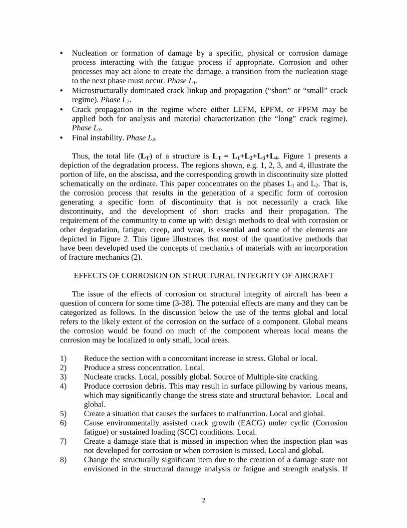
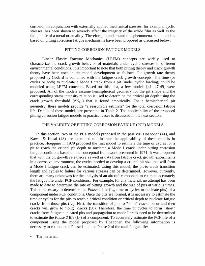
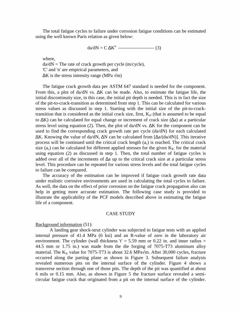
internal pressure of 41.4 MPa (6 ksi) and an R-value of zero in the laboratory airenvironment. The cylinder (wall thickness 't' = 5.59 mm or 0.22 in. and inner radius =44.5 mm or 1.75 in.) was made from the die forging of 7075-T73 aluminum alloymaterial. The KIc value for 7075-T73 is about 32.6 MPa√m. After 30,000 cycles, fractureoccurred along the parting plane as shown in Figure 3. Subsequent failure analysisrevealed numerous pits on the internal surface of the cylinder. Figure 4 shows atransverse section through one of those pits. The depth of the pit was quantified at about6 mils or 0.15 mm. Also, as shown in Figure 5 the fracture surface revealed a semi-circular fatigue crack that originated from a pit on the internal surface of the cylinder.

10
The crack depth (a) and crack width (2c) were found to be 4.32 mm (0.17 in.) and 9.65mm (0.38 in.) respectively (52). Nominal hoop stress at the fracture location wascalculated at about 331.2 MPa (48 ksi). The calculated hoop stress was about 68% of theparent material ultimate strength and 80% of the nominal design stress (414 MPa or 60ksi) for the component.
As there is no data available with regard to the pit growth rate for 7075-T73, thePhase 1 life, that is, the time or cycles to nucleate the pit, from which the crack formedresulting in fracture of the cylinder, can not be estimated. In addition, fatigue crackgrowth rate data for 7075-T73 in a realistic environment is not available to estimate thenumber of fatigue cycles for fracture of the cylinder. However, fatigue crack growth ratedata for 7075-T73 in a laboratory environment will be used in the estimation. Therefore,with the available information from the failure analysis, the applicability of the PCFmodels proposed by Hoeppner (41) and Kawai & Kasai (48) to the shock-strut cylinder isdemonstrated below.
Calculation of critical stress intensity factor at fracture:From equation (2), the critical stress intensity factor at fracture can be calculated.
Considering the measured crack depth value from the failure analysis as 'a', the calculatedσhoop as σ and Q is assumed as 2.48, the critical stress intensity factor at fracture is foundto be 26.95 MPa√m. However, as mentioned before, the KIc value for 7075-T73 wasabout 32 MPa√m. The lower KIc value at fracture could be attributed to numerous pitsthat were found on the surfaces of the cylinder.
Estimation of pit to crack-transition length:Using equation (2) from Hoeppner's PCF model, the pit-to-crack transition can be
estimated. For σ = σhoop = 331.2 MPa, Ksf = ∆Kscth = 0.75 MPa√m (for 7075-T6 from ref.50), the pit-to-crack-transition length is determined to be 0.0035 mm.
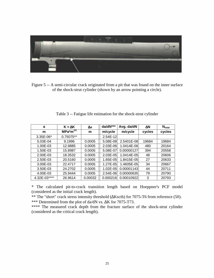
Estimation of fatigue cycles to failure:Considering the pit-to-crack-transition length (0.0035 mm) as the initial crack size
and the measured crack depth from the failure analysis (4.32 mm) as the critical cracksize, the number of fatigue cycles to failure once the pit is transitioned to a crack isdetermined as shown in Table 3. The procedure outlined in the previous section is used inestimating the number of cycles to failure. The fatigue crack growth rate data for 7075-T73 is used in determining da/dN for each calculated ∆K. As determined from Table 3,the estimated number of cycles to failure is 20,793. When it is compared to the actualcycles to fracture from testing, that is, 30,000 cycles, it is a reasonable estimate.
Estimation of the allowable stress:Using the model proposed by Kawai and Kasai, the allowable stress at which the
shock-strut cylinder can be operated is determined using equation (1). In this equation,∆Kall (allowable stress intensity threshold value) is considered equal to the "long" crackthreshold stress intensity value for 7075-T73, that is, 5 MPa√m (from ref. 51). Thegeometric factor 'F' is assumed as 1. The quantified depth of pit (6 mils or 1.5e-04 m) onthe inner surface of the cylinder from failure analysis is considered as hmax, that is, themaximum pit depth. Substituting these values in equation (1), the estimated allowable

11
stress at which the shock-strut cylinder can be operated is determined to be 230.3 MPa. Itis about 30% lower when compared to the calculated hoop stress (331.2 MPa) at thefracture location of the shock-strut cylinder.
SUMMARY AND CONCLUSIONS
This paper reviewed some PCF models and discussed their usefulness andlimitations in estimating the total fatigue life of a component. The applicability of PCFmodels was demonstrated with a realistic case study involving the fatigue failure of alanding gear shock-strut cylinder. Some examples of critical pitting corrosion fatigueincidents in aircraft and helicopter components were provided to illustrate thesignificance of developing more realistic models to address this particular failuremechanism. To accomplish this, fatigue growth rate data in a realistic environment needto be generated. Also, the materials response to nucleation of pits and their growth rateunder various stresses and environments should be studied.
ACKNOWLEDGMENTS
The research reported herein was performed as a part of the research program"Modeling corrosion growth on aircraft structure" for NCI Information Systems,Fairborn, OH, under contract NCI USAF 9138-003 with Mr. Garth Cooke as the programmanager. The support of NCI Information Systems in conducting this research isgratefully acknowledged. The authors also would like to thank the University of Utah foruse of facilities and encouragement.

12
REFERENCES
1) Hoeppner, D.W., "Parameters that Input to Application of Damage ToleranceConcepts to Critical Engine Components," AGARD Conference Proceedings No.393, Damage Tolerance Concepts for Critical Engine Components, 1986, pp. 4-1- 4-16.
2) Hoeppner, D.W., and Chandrasekaran, V., "Corrosion and Corrosion FatiguePredictive Modeling - State of the Art Review," FASIDE report to NCIInformation Systems, Fairborn, OH, 1998.
3) Stress Corrosion Cracking in Aircraft Structural Materials, AGARD ConferenceProceedings Series 18, Report of a two day Symposium held by the Structures andMaterials Panel of AGARD in Turin, Italy, 18,19 April, 1967, NATO-AGARD,64 Rue De Varenne, Paris, France, 1967.
4) Fundamental Aspects of Stress Corrosion Cracking, Editors: Staehle, R. W, Forty,A.J., van Rooyen, D., Proceedings of a conference held at the Ohio StateUniversity, 11-15Sept. 1967, NACE-1, National Association of CorrosionEngineers, Houston, TX, 1969.
5) Effects of Environment and Complex Load History on Fatigue Life, ASTM STP462, Proceedings of the Symposium on Effects of Environment and ComplexLoad History on Fatigue Life held in Atlanta, GA, 29Sept. -4Oct., 1968, Editedby M. Rosenfeld, D.W. Hoeppner, and R. I. Stephens, ASTM, Philadelphia, PA.,1970.
6) Corrosion Fatigue: Chemistry, Mechanics, and Microstructure, Editors:,Devereux, O., McEvily, A.J., Staehle, R. W., Proceedings of the Conference heldat the University of Connecticut, 14-18June1971, NACE-2, National Associationof Corrosion Engineers, Houston, TX, 1973.
7) Brown, B.F., Stress-Corrosion Cracking in High Strength Steels and in Titaniumand Aluminum Alloys,, Naval Research Laboratory, Washington, D.C., 1972.
8) Hall, L.R., Finger, R.W., Spurr, W.F., “Corrosion Fatigue Crack Growth inAircraft Structural Materials”, AFML-TR-73-204, Boeing Company, September,1973.
9) Pettit, D., Ryder, J., Krupp, W., Hoeppner, D., “Investigation of the Effects ofStresss and Chemical Environments on the Prediction of Fracture in AircraftStructural Materials”, AFML-TR-74-183, Lockheed California Company,December, 1974.

13
10) Corrosion-Fatigue Technology, ASTM STP 642, Proceedings of a Symposiumheld in Denver, CO, 14-19 Nov.1976, Edited by H.L.Craig, Jr., T.W. Crooker,and D. W. Hoeppner, ASTM, Philadelphia, PA, 1978.
11) Aircraft Corrosion, AGARD Conference Proceedings No. 315, Papers presentedat the 52nd Meeting of the AGARD Structures and Materials Panel Meeting heldin Cesme, Turkey, 5-10 April 1981, , NATO-AGARD, 64 Rue De Varenne, Paris,France, 1981.
12) Corrosion Fatigue, AGARD Conference Proceedings No. 316, Papers Paperspresented at the 52nd Meeting of the AGARD Structures and Materials PanelMeeting held in Cesme, Turkey, 5-10 April 1981, , NATO-AGARD, 64 Rue DeVarenne, Paris, France, 1981.
13) Corrosion Fatigue, ASTM STP 801, Proceedings of the Symposium on CorrosionFatigue: Mechanics, Metallurgy, Electrochemistry, and Engineering held in St.Louis, MO21-22 OCT. 1981, Edited by T.W. Crooker, B.N.Leis, ASTM,Philadelphia, PA., 1983.
14) Campbell, G. S., Lahey, R., Int. J. Fatigue, Vol. 6, No. 1, 1984, pp. 25-30. MetalsHandbook, 9th ed., Vol. 13, Corrosion, American Society for Metals, MetalsPark, Ohio, 1985, pp. 584-609
15) Wallace, W., Hoeppner, D., Kandachar, P. V., “Aircraft Corrosion: Causes andCase Histories”, AGARD Corrosion Handbook, Vol. 1, , AGARD-AG-278-Vol.1, 1985.
16) ASM Handbook, Vol. 13, Corrosion, ASM International, Metals Park, Ohio,1987.
17) The Boeing Company, Corrosion Prevention and Control, Manual for TrainingOperators of Boeing Commercial. Aircraft, Seattle, WA, 1988.
18) NTSB Metallurgist’s Report, “Aloha Airlines Flight 243,” Materials LaboratoryReport 88-85, 1988.
19) Environment Induced Cracking of Metals, Editors: Gangloff, R.P., Ives, M.B.,Proceedings of the conference held in Kohler, WI, 2-7Oct. 1988, NACE-10,National Association of Corrosion Engineers, Houston, TX, 1990
20) ASM Handbook, Volume 18, Friction, Lubrication, and Wear Technology, ASMInternational, Metals Park, Ohio,, 1992
21) Naval Aviation Safety Program, US Navy, OPNAVINST 3750.6Q CH-1, OP-05F, March 1991.

14
22) Federal Aviation Administration, Aircraft Accident and Incident SynopsesRelated to Corrosion, Fretting, and Fatigue for the Period 1976-1993, obtainedJuly 1994.
23) National Transportation Safety Board, Aircraft Accident and Incident SynopsesRelated to Corrosion, Fretting, and Fatigue for the Period 1975-1993, obtainedJuly 1994.
24) Federal Aviation Administration, Aircraft Accident and Incident SynopsesRelated to Corrosion, Fretting, and Fatigue for the Period 1976-1993, obtainedJuly 1994.
25) Karpala, F., Hageniers, O.L., “Characterization of Corrosion and Development ofa Broadboard Model of a D sight Aircraft Inspection System”, Phase 1, DiffractoLtd., Report to DOT, August, 1994.
26) United States Air Force, Navy, and Army, Aircraft Accident and IncidentSynopses Related to Corrosion, Fretting, and Fatigue, obtained June-August 1994.
27) Cooke, G. Vore, P.J., Gumienny, C., Cooke, G. Jr., “A Study to Determine theAnnual Direct Cost of Corrosion Maintenance for Weapon Systems andEquipment in the United States Air Force”, Final Report, Contract NumberF09603-89-C-3016, SEPT., 1990.
28) Schutz, W., “Corrosion Fatigue-The Forgotten Factor in Assessing Durability”,ICAF 95, Estimation, Enhancement and Control of Aircraft Fatigue Performance,Vol. 1, Edited by J.M. Grandage, G.S. Jost, Proceedings of the 18th Symposiumon the International Committee of Aeronautical Fatigue, 3-5 May, 1995,Melbourne, Australia, EMAS, Warley, West Midlands, U.K., 1995, pp 1-52.
29) Swift,S.J., “The Aero Commander Chronicle”, ICAF 95, Estimation,Enhancement and Control of Aircraft Fatigue Performance, Vol. 1, Edited by J.M.Grandage, G.S. Jost, Proceedings of the 18th Symposium on the InternationalCommittee of Aeronautical Fatigue, 3-5 May, 1995, Melbourne, Australia,EMAS, Warley, West Midlands, U.K., 1995, pp 507-530.
30) Hoeppner, D.W., Grimes, L., Hoeppner, A., Ledesma, J., Mills, T., Shah, A., “Corrosion and Fretting as Critical Aviation Safety Issues”, ICAF 95, Estimation,Enhancement and Control of Aircraft Fatigue Performance, Vol. 1, Edited by J.M.Grandage, G.S. Jost, Proceedings of the 18th Symposium on the InternationalCommittee of Aeronautical Fatigue, 3-5 May, 1995, Melbourne, Australia,EMAS, Warley, West Midlands, U.K., 1995, pp 87-106.
31) Brooks, C.L., Liu, K., Eastin, R.G., “Understanding Fatigue Failure AnalysesUnder Random Loading Using a C-17 Test Article”, ICAF 95, Estimation,

15
Enhancement and Control of Aircraft Fatigue Performance, Vol. 1, Edited by J.M.Grandage, G.S. Jost, Proceedings of the 18th Symposium on the InternationalCommittee of Aeronautical Fatigue, 3-5 May, 1995, Melbourne, Australia,EMAS, Warley, West Midlands, U.K., 1995, pp 449-468.
32) ASM Handbook, Vol. 19, Fatigue and Fracture, ASM International, Metals Park,Ohio,, 1996.
33) Schmidt, C.G., Crocker, J.E., Giovanola, J.H., Kanazawa, C.H., Schockey,“Characterization of Early Stages of Corrosion Fatigue in Aircraft Skin”, FinalReport, Contract No. 93-G-065, SRI International Final Report to DOT, MenloPark, CA, Report No. DOT/FAA/AR-95/108, February, 1996.
34) Cole, G.K., Clark, G., Sharp, P.K., Implications of Corrosion With Respect toAircraft Structural Integrity, DSTO –RR-0102, AMRL, Melbourne, Australia,March, 1997.
35) Aging of U.S. Air Force Aircraft, Report of the Committee on Aging of U.S. AirForce Aircraft, NMAB (National Materials Advisory Board), Commission onEngineering and Technical Systems, National Research Council, PublicationNMAB-488-2, 1997.
36) Boeing, Corrosion Damage Assessment Framework, Corrosion/Fatigue Effects onStructural Integrity, Report D500-13008-1, USAF Contract No. F9603-97-C-0349. 1998.
37) Paul, C., Mills, T., “Corrosion/Fatigue”, Presentation made at AeroMat, “A Studyto Determine the Cost of Corrosion Maintenance for Weapon Systems andEquipment in the United States Air Force”, Final Report, Contract NumberF09603-95-D-0053, February 1998.
38) Fatigue in the Presence of Corrosion, RTO Proceedings 18, Papers Presented atthe Workshop of the RTO Applied Technology (AVT) Panel, held in Corfu,Greece, 7-9 October, 1998, AC/323(AVT) TP/8, NATO, Research andTechnology Orgranization, BP 25, 7 Rue Ancelle, F-92201, Neully-Sur-Seine,Cedix, France, 1999.
39) Hoeppner, D.W., Mann, and Weekes, “Fracture Mechanics Based Modelling of
Corrosion Fatigue Process,” in Corrosion Fatigue: Proceedings of the 52nd
meeting of the AGARD Structural and Materials Panel held in Turkey, 5-10April, 1981.
40) Hoeppner, D.W., Corrosion Fatigue Considerations in Materials Selections andEngineering Design”, Corrosion Fatigue: Chemistry, Mechanics, andMicrostructure, NACE, 1972, pp. 3-11.
16
41) Hoeppner, D.W., “Model for Prediction of Fatigue Lives Based Upon a PittingCorrosion Fatigue Process,” Fatigue Mechanisms, Proceedings of an ASTM-NBS-NSF Symposium, J.T. Fong, Ed., ASTM STP 675, American Society forTesting and Materials, 1979 pp. 841-870.
42) McAdam, D.J., and Gell, G.W., “Pitting and Its Effect on the Fatigue Limit ofSteels Corroded Under Various Conditions”, Journal of the Proceedings of theAmerican Society for Testing Materials, Vol. 41, 1928, pp. 696-732.
43) Goto, M., and Nisitani, H., “Crack Initiation and Propagation Behavior of a Heattreated Carbon Steel in Corrosion Fatigue”, Fatigue Fracture EngineeringMaterial Structure, Vol. 15, No. 4, 1992, pp. 353-363.
44) Muller, M., “Theoretical Considerations on Corrosion Fatigue Crack Initiation”,Metallurgical Transactions, Vol. 13A, 1982, pp. 649-655.
45) Mehdizadeh, P., et al., “Corrosion Fatigue Performance of a Carbon Steel in BrineContaining Air, H2S, CO2”, Corrosion, Vol. 22, 1966, pp. 325-335.
46) Corsetti, L.V., and Duquette, D.J., “The Effect of Mean Stress and Environmenton Corrosion Fatigue Behavior of 7075-T6 Aluminum”, MetallurgicalTransactions, Vol. 5, 1974, pp. 1087-1093.
47) Lindley, T. C., McIntyre, P., and Trant, P. J., “Fatigue Crack Initiation atCorrosion Pits,” Metals Technology, Vol. 9, 1982, pp. 135-142.
48) Kawai, S. and Kasai, K., “Considerations of Allowable Stress of CorrosionFatigue (Focused on the Influence of Pitting),” Fatigue Fracture of EngineeringMaterials Structure, Vol. 8, No. 2, 1985, pp. 115-127.
49) Kondo, Y., “Prediction of Fatigue Crack Initiation Life Based on Pit Growth,”Corrosion Science, Vol. 45, No. 1, 1989, pp. 7-11.
50) Newman Jr., J.C., Phillips, E.P., and Swain, M.H., "Fatigue-Life PredictionMethodology Using Small-Crack Theory," International Journal of Fatigue, 21,1999, pp. 109-119.
51) Bowie, G.E., Van Orden, J.M., Besari, M.S., Pettit, D.E., Weber, K.E., Krupp,W.E., Fairchild, J., and Meyer, D.R., Correlation of Failure Analysis Data: PittingCorrosion, LR 27399, Lockheed-California Company Report, 1975.
52) Hoeppner, D.W., Prevention of Fracture in Materials, Lockheed ContinuingEducation Course, 1970.

17
������������������������������������������������������������������������������������������������������������������������������������������������������������������������������������������������������������������������������������������������������������������������������������������������������������������������������������������������������������������������������������������������������������������������������������������������������������������������������������������������������������������������������������������������������������������������������������������������������������������������������������������������������������������������������������������������������������������������������������������������������������������������������������������������������������������������������������������������������������������������������������������������������������������������������������������������������������������������������������������������������������������������������������������������������������������������������������������������������������������������������������������������������������������������������������������������������������������������������������������������������������������������������������������������������������������������������������������������������������������������������������������������������������������������������������������������������������������������������������������������������������������������������������������������������������������������������������������������������������������������������������������������������������������������������������������������������������������������������������������������
Discontinuity Size
Life
A
4
A= "FIRST" detectable crack 1. Nucleation phase, "NO CRACK" 2. "SMALL CRACK" phase-steps related to local structure (Anisotropy) 3. Stress dominated crack growth, LEFM, EPFM 4. Crack at length to produce instability
1 2 3
The degradation process
Figure 1 -- A depiction of the degradation process (after Hoeppner-1971, 1986).

18
METHODS FOR EACH LIFE PHASE
Effects of •R ratio •Stress state •Environment •Spectrum -waveform
Nucleated discontinuity (not inherent) type, size, location
NUCLEATION
Material failure mechanism with appropriate stress/strain life data
Presence of malignant D*, H*
Possibility of extraneous effects •Corrosion •Fretting •Creep •Mechanical Damage
"SMALL CRACK" GROWTH
Crack Prop. threshold related to structure (micro)
Structure dominated crack growth
Mechanisms, rate
Onset of stress dominated crack growth
Data base**
Appropriate stress intensity factor Initial D*, H* size, location, type
Effects of •R ratio •Stress state •Environment •Spectrum -waveform
t
chem
T
STRESS DOMINATED CRACK GROWTH
Fracture mechanics •similitude •boundary cond.
LEFM
EPFM?
FAILURE (FRACTURE)
C.O.D.
Tensile/ compressive buckling
KIc
t
chem
T
etc.
Figure 2 -- Methods for each life phase (after Hoeppner-1971, 1986).
NOTE: Initiation as frequently used by the technical community is usuallypart of the nucleation (or formation), short crack growth, and stressdominated crack growth phase of life. One is never sure however howmuch of the life is taken up by the traditional use of the “initiation”concept. To avoid this we have used the term initiation herein only to referto the beginning of a specific degradation process such as corrosion,fatigue, or initiation of crack propagation. As depicted in Figure 1 whatoften is referred to as “initiation” is life to a certain detectable crack sizeor damage size. This is a critical distinction in that use of “first” crackdetection concepts, or related on condition evaluation terms, forces thedesigner to think about inspectability and detectability of specific forms ofdegradation. As well, it is imperative that the technical communitydevelop an understanding of the nucleation and growth phases ofdegradation processes.

19
Table 1 -- Pitting corrosion incidents of aircraft and helicopters
Aircraft Location ofFailure
Cause IncidentSeverity
Place Year From
BellHelicopter
Fuselage,longeron
Fatigue, corrosionand pitting present
Serious AR,USA.
1997 NTSB
DC-6 Engine, masterconnecting rod
Corrosion pitting Fatal AK,USA.
1996 NTSB
Piper PA-23 Engine,cylinder
Corrosion pitting Fatal AL,USA.
1996 NTSB
Boeing 75 Rudder Control Corrosion pitting Substantialdamage toplane
WI,USA.
1996 NTSB
Embraer120
Propeller Blade Corrosion pitting Fatal andserious, loss ofplane
GA,USA.
1995 NTSB
GulfstreamGA-681
Hydraulic Line Corrosion pitting Loss of plane,no injuries
AZ,USA.
1994 NTSB
L-1011 Engine,compressorassembly disk
Corrosion pitting Loss of plane,no injuries
AK,USA.
1994 NTSB
Embraer120
Propeller Blade Corrosion pitting Damage toplane, noinjuries
Canada 1994 NTSB
Embraer120
Propeller Blade Corrosion pitting Damage toplane, noinjuries
Brazil 1994 NTSB
F/A-18 Trailing-edgeFlap (TEF)Outboard HingeLug
Corrosion pitting,fatigue
Loss of TEF Australia 1993 AMRL
MooneyMooney 20
Engine, interior Corrosion pitting,improper approach
Minor injuries TX,USA.
1993 NTSB
AeroCommander680
Lower SparCap
Corrosion pitting Fatal Sweden 1990 SwedishCAA

20
Table 2 -- Pitting corrosion fatigue models
Proposedby
Summary Description Advantages/Limitations
1 Hoeppner(1971 -current)
• Proposed a modelto determinecritical pit depth tonucleate a Mode Icrack under pittingcorrosion fatigueconditions.
• combined with thepit growth ratetheory as well asthe fatigue crackgrowth curve fit ina corrosiveenvironment, thecycles needed todevelop a criticalpit size that willform a Mode Ifatigue crackcan be estimated.
• Using a four parameter Weibullfit, fatigue crack growththreshold (∆Kth) was found fromcorrosion fatigue experiments forthe particular environment,material, frequency, and loadspectrum.
• The stress intensity relation forsurface discontinuity (half pennyshaped crack) was used tosimulate hemispherical pit.
i.e.) K = 1.1 σ π a
Q
where, σ is the applied stress, a is thepit length, and Q is the function ofa/2c, Sty.
• Using the threshold determinedempirically, critical pit depth wasfound from the stress intensityrelation mentioned above.
• Then, the time to attain the pitdepth for the correspondingthreshold value was found using
t = d
c
3
where, t is the time, d is the pit depth,and c is a material/environmentparameter.
• This modelprovides areasonableestimate forhemisphericalgeometry of thepits.
• This model isuseful toestimate thetotal corrosionfatigue life withknowledge ofthe kinetics ofpittingcorrosion andfatigue crackgrowth.
• This model didnot attempt toproposemechanisms ofcracknucleation fromcorrosion pits.
• This model isvalid only forthe conditionsin which LEFMconcepts areapplicable.
• Materialdependent.
21
Proposedby
Summary Description Advantages/Limitations
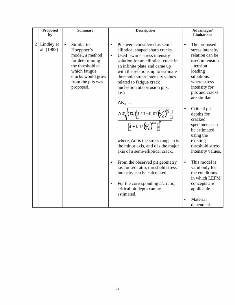
2 Lindley etal. (1982)
• Similar toHoeppner’smodel, a methodfor determiningthe threshold atwhich fatiguecracks would growfrom the pits wasproposed.
• Pits were considered as semi-elliptical shaped sharp cracks
• Used Irwin’s stress intensitysolution for an elliptical crack inan infinite plate and came upwith the relationship to estimatethreshold stress intensity valuesrelated to fatigue cracknucleation at corrosion pits.i.e.)
∆Kth =
∆σ πa( ) 1.13 −0.07 ac( )
12
1 +1.47 ac( )1.64
12
where, ∆σ is the stress range, a isthe minor axis, and c is the majoraxis of a semi-elliptical crack.
• From the observed pit geometryi.e. for a/c ratio, threshold stressintensity can be calculated.
• For the corresponding a/c ratio,
critical pit depth can beestimated.
• The proposedstress intensityrelation can beused in tension- tensionloadingsituationswhere stressintensity forpits and cracksare similar.
• Critical pitdepths forcrackedspecimens canbe estimatedusing theexistingthreshold stressintensity values.
• This model isvalid only forthe conditionsin which LEFMconcepts areapplicable.
• Material
dependent.

22
Proposedby
Summary Description Advantages/Limitations
3 Kawai andKasai(1985)
• Proposed a modelbased onestimation ofallowable stressesunder corrosionfatigue conditionswith emphasis onpitting.
• As corrosion is not
usually consideredin developing S-Nfatigue curves, amodel forallowable stressintensity thresholdinvolvingcorrosion fatigueconditions wasproposed.
• Considered corrosion pit as anelliptical crack.
• Based on experimental datagenerated on stainless steel, newallowable stresses based onallowable stress intensitythreshold was proposed.
i.e.)
∆σall =∆kall
F πhmax
where, ∆Kall can be determined from
a da/dN vs. ∆K plot for a material,hmax is the maximum pit depth, andF is a geometric factor.
• Using thismodel,allowable stressin relation tocorrosionfatiguethreshold as afunction of timecan beestimated.
• Materialdependent.
• This model isvalid only forthe conditionsin which LEFMconcepts areapplicable.

23
Proposedby
Summary Description Advantages/Limitations
4 Kondo(1989)
• Corrosion fatiguelife of a materialcould bedetermined byestimating thecritical pitcondition usingstress intensityfactor relation aswell as the pitgrowth raterelation.
• Pit diameter was measuredintermittently during corrosionfatigue tests.
• From test results, corrosion pitgrowth law was expressed as
2c α Cp t1/3
where, 2c is the pit diameter, t is thetime, and Cp is anenvironment/material parameter.Then, critical pit condition (∆Kp) in
terms of stress intensity factorwas proposed by assuming pit asa crack.
∆Kp = 2.24σaπcα
Q
where, σa is the stress amplitude, a isthe aspect ratio, and Q is the shapefactor.• Critical pit condition was
determined by the relationshipbetween the pit growth ratetheory and fatigue crack growthrates.
c = cp (N/f)1/3
where, N is the number of stresscycles, f is the frequency, and 2c isthe pit diameter.• The pit growth rate dc/dN was
developed using ∆K relation asgiven below.
dcdN =
1
3
Cp
3 f −1α 2π2Q−2 2.24σ a( )4∆K −4
dc/dN was determined usingexperimental parameter Cp.
• Finally, the critical pit size 2Ccrwas calculated from the stressintensity factor relation.
i.e.) 2Ccr = (2Q/πα)( ∆Kp/2.24σa)2
• The aspect ratiowas assumed asconstant.
• Material andenvironmentdependent.

24
Figure 3 -- Fracture along the parting plane of 7075-T73 shock-strut cylinder.
Figure 4 -- A transverse section of a pit on the inner surface of the shock-strut cylinder.Note a fatigue crack nucleated from the pit.
25
Figure 5 -- A semi-circular crack originated from a pit that was found on the inner surfaceof the shock-strut cylinder (shown by an arrow pointing a circle).
Table 3 -- Fatigue life estimation for the shock-strut cylinder
a K = ∆ ∆ ∆ ∆K ∆∆∆∆a da/dN*** Avg. da/dN ∆∆∆∆N Ntotal
m MPa*m1/2 m m/cycle m/cycle cycles cycles
3.35E-06* 0.75075** 2.54E-125.03E-04 9.1996 0.0005 5.08E-08 2.5401E-08 19684 196841.00E-03 12.9885 0.0005 2.03E-06 1.0414E-06 480 201641.50E-03 15.8987 0.0005 5.08E-07 0.00000127 394 205582.00E-03 18.3532 0.0005 2.03E-05 1.0414E-05 48 206062.50E-03 20.5160 0.0005 1.65E-05 1.8415E-05 27 206333.00E-03 22.4717 0.0005 1.27E-05 1.4605E-05 34 206673.50E-03 24.2702 0.0005 1.02E-05 0.00001143 44 207114.00E-03 25.9444 0.0005 2.54E-06 0.00000635 79 20790
4.32E-03**** 26.9614 0.00032 0.000216 0.00010922 3 20793
* The calculated pit-to-crack transition length based on Hoeppner's PCF model(considered as the initial crack length).** The "short" crack stress intensity threshold (∆Kscth) for 7075-T6 from reference (50).*** Determined from the plot of da/dN vs. ∆K for 7075-T73.**** The measured crack depth from the fracture surface of the shock-strut cylinder(considered as the critical crack length).
Recommended