Research in Soft Magnetic Materials at NASA Glenn
Randy Bowman
NASA Glenn Research CenterAugust 10th, 2017
IAPG Electrical Systems Working Group Meeting, August 8-10, 2017NASA Glenn Research Center • Cleveland, OH
https://ntrs.nasa.gov/search.jsp?R=20170009389 2020-08-07T06:55:15+00:00Z
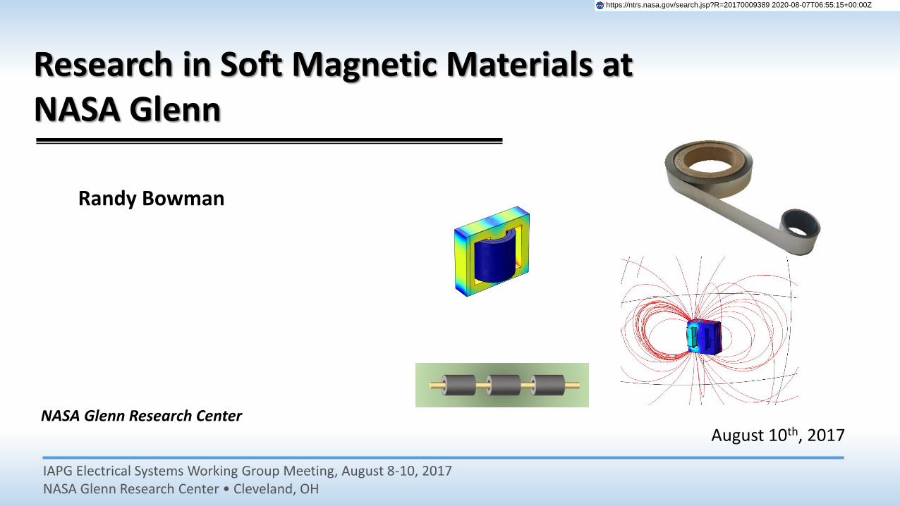
Establishment of Magnetics Research Activities
Motivation for Entering the Field:
Magnetic materials have not historically been an active research topic at NASA GRC
• Thus far, the AATT project has provided the majority of the funding needed to establish the magnetics program at GRC.
• Program has been highly focused thus far on scale-up, manufacturability and component fabrication to support hybrid electric concepts.
• Also pursuing fundamental research on material behavior and alloy development.
• Funding has been augmented by other internal and external programs. • Producing hardware and testing for external programs.• Establishing a commercialization path with industry for these materials.
Support and Main Activities:
Center-Level Motivation – Develop GRC expertise and capabilities in magnetic materials and initiate a presence in the application and research communities to support the future direction of NASA GRC, which emphasizes more vehicle electrification and “green” power generation and power conversion technologies.
Specific Tasks - Support the needs of the Advanced Air Transport Technology (AATT) Project by developing more capable soft and hard magnetic materials for use in motors, power conversion, and control circuitry for the Hybrid electric program.
Establishment of Magnetics Research Activities
The timing of NASA’s interest in magnetics was fortuitous. NETL and CMU groups were looking for a location to host the large melt spin casters.
Equipment
3-kg caster – Returning this unit to operational status was key to producing large-scale components. This is necessary for determining the behavior of developmental alloys under relevant operating conditions.
Partnerships
Gave NASA access to the corporate knowledge that the NETL/CMU teams had accumulated and allowed us to contribute quickly.
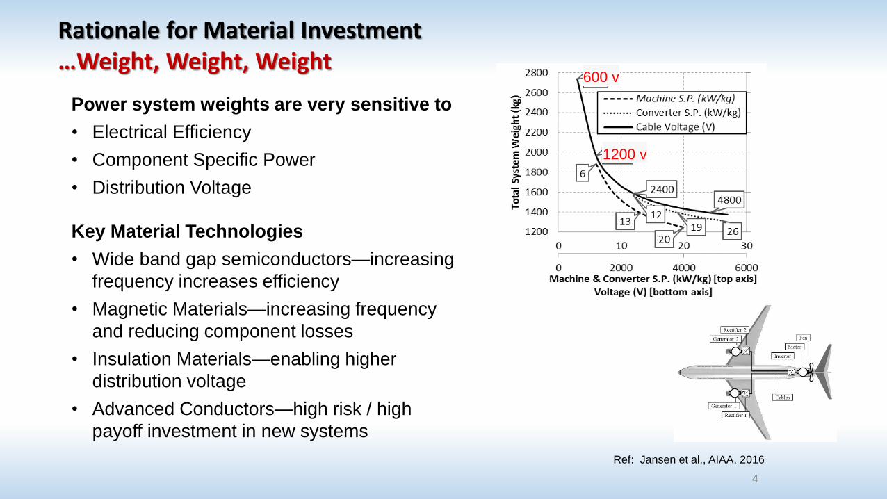
Rationale for Material Investment…Weight, Weight, Weight
4
Ref: Jansen et al., AIAA, 2016
600 v
1200 v
Power system weights are very sensitive to
• Electrical Efficiency
• Component Specific Power
• Distribution Voltage
Key Material Technologies
• Wide band gap semiconductors—increasing
frequency increases efficiency
• Magnetic Materials—increasing frequency
and reducing component losses
• Insulation Materials—enabling higher
distribution voltage
• Advanced Conductors—high risk / high
payoff investment in new systems
5
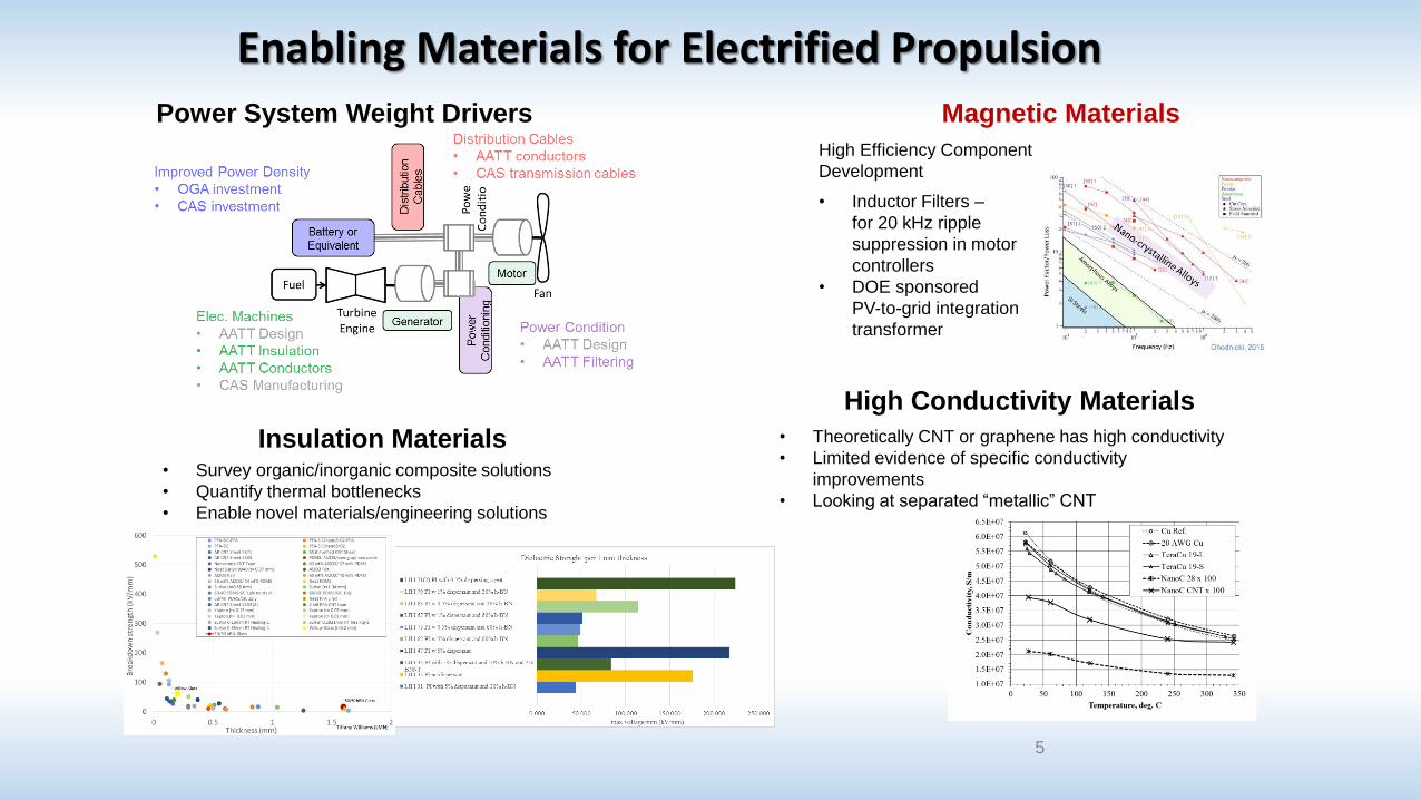
Power System Weight Drivers Magnetic Materials
Insulation Materials
High Efficiency Component
Development
• Inductor Filters –
for 20 kHz ripple
suppression in motor
controllers
• DOE sponsored
PV-to-grid integration
transformer
High Conductivity Materials
• Survey organic/inorganic composite solutions
• Quantify thermal bottlenecks
• Enable novel materials/engineering solutions
• Theoretically CNT or graphene has high conductivity
• Limited evidence of specific conductivity
improvements
• Looking at separated “metallic” CNT
Enabling Materials for Electrified Propulsion
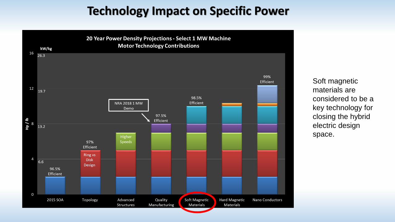
Technology Impact on Specific Power
Soft magnetic
materials are
considered to be a
key technology for
closing the hybrid
electric design
space.
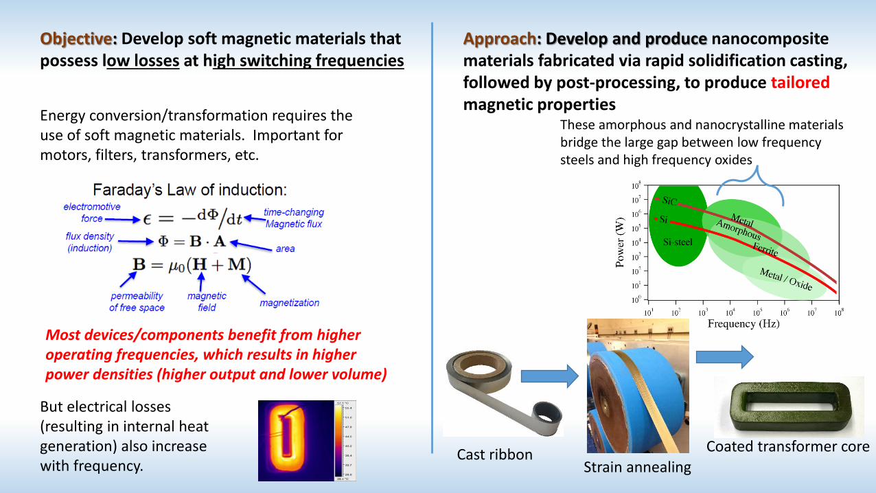
Objective: Develop soft magnetic materials that possess low losses at high switching frequencies
Approach: Develop and produce nanocomposite materials fabricated via rapid solidification casting, followed by post-processing, to produce tailoredmagnetic properties
Energy conversion/transformation requires the use of soft magnetic materials. Important for motors, filters, transformers, etc.
But electrical losses (resulting in internal heat generation) also increase with frequency.
Cast ribbonStrain annealing
Coated transformer core
These amorphous and nanocrystalline materials bridge the large gap between low frequency steels and high frequency oxides
Most devices/components benefit from higher operating frequencies, which results in higher power densities (higher output and lower volume)
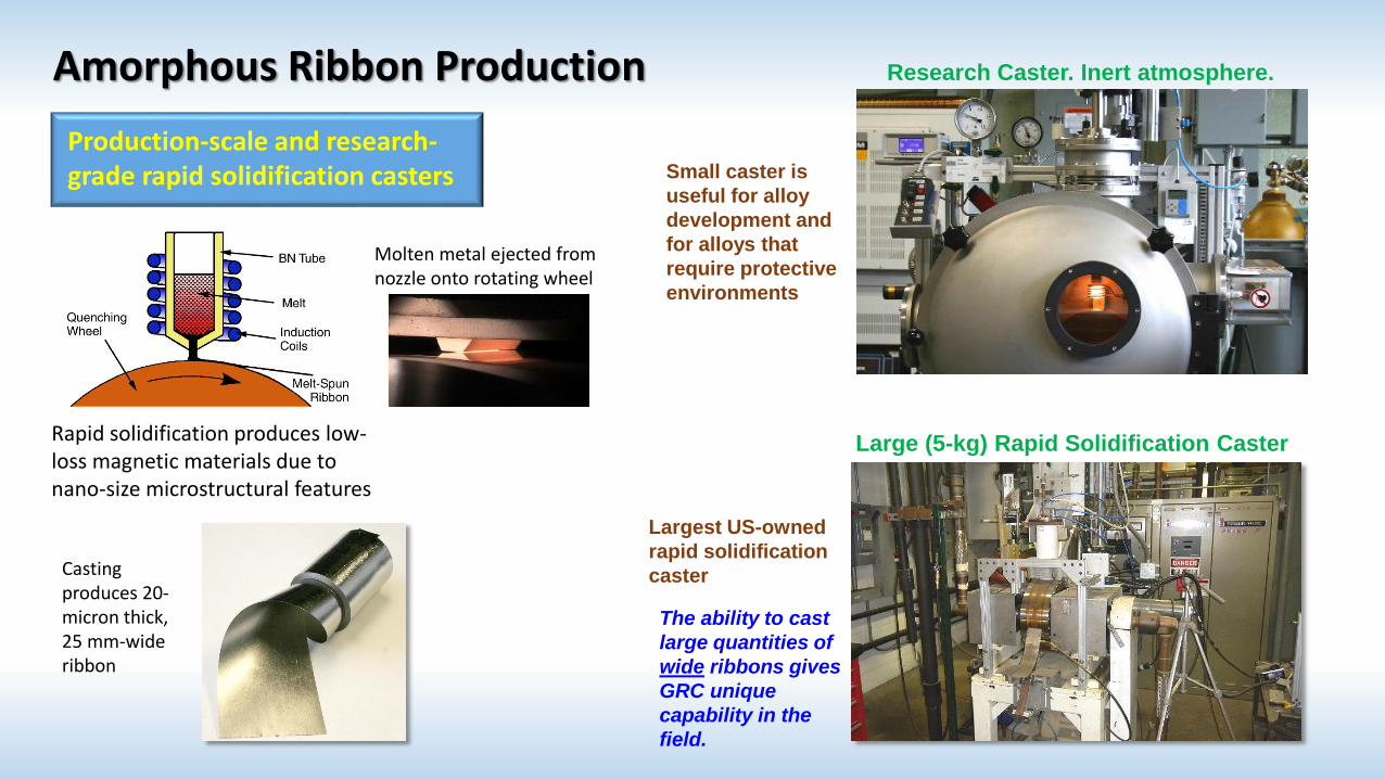
Amorphous Ribbon Production
Largest US-owned
rapid solidification
caster
Large (5-kg) Rapid Solidification Caster
The ability to cast
large quantities of
wide ribbons gives
GRC unique
capability in the
field.
Production-scale and research-grade rapid solidification casters
Rapid solidification produces low-loss magnetic materials due to nano-size microstructural features
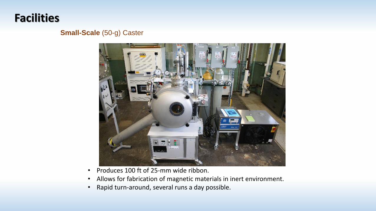
Casting produces 20-micron thick, 25 mm-wide ribbon
Research Caster. Inert atmosphere.
Small caster is
useful for alloy
development and
for alloys that
require protective
environments
Molten metal ejected from nozzle onto rotating wheel
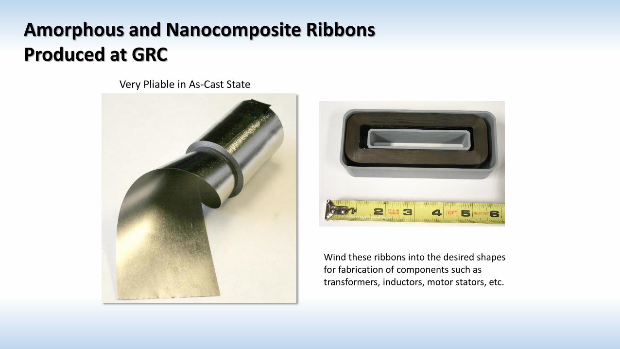
Very Pliable in As-Cast State
Wind these ribbons into the desired shapes for fabrication of components such as transformers, inductors, motor stators, etc.
Amorphous and Nanocomposite Ribbons Produced at GRC
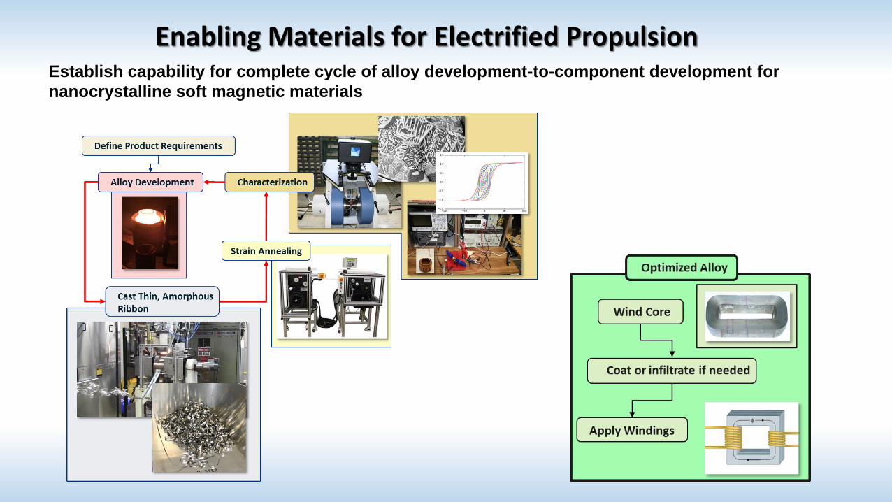
Enabling Materials for Electrified PropulsionEstablish capability for complete cycle of alloy development-to-component development for
nanocrystalline soft magnetic materials
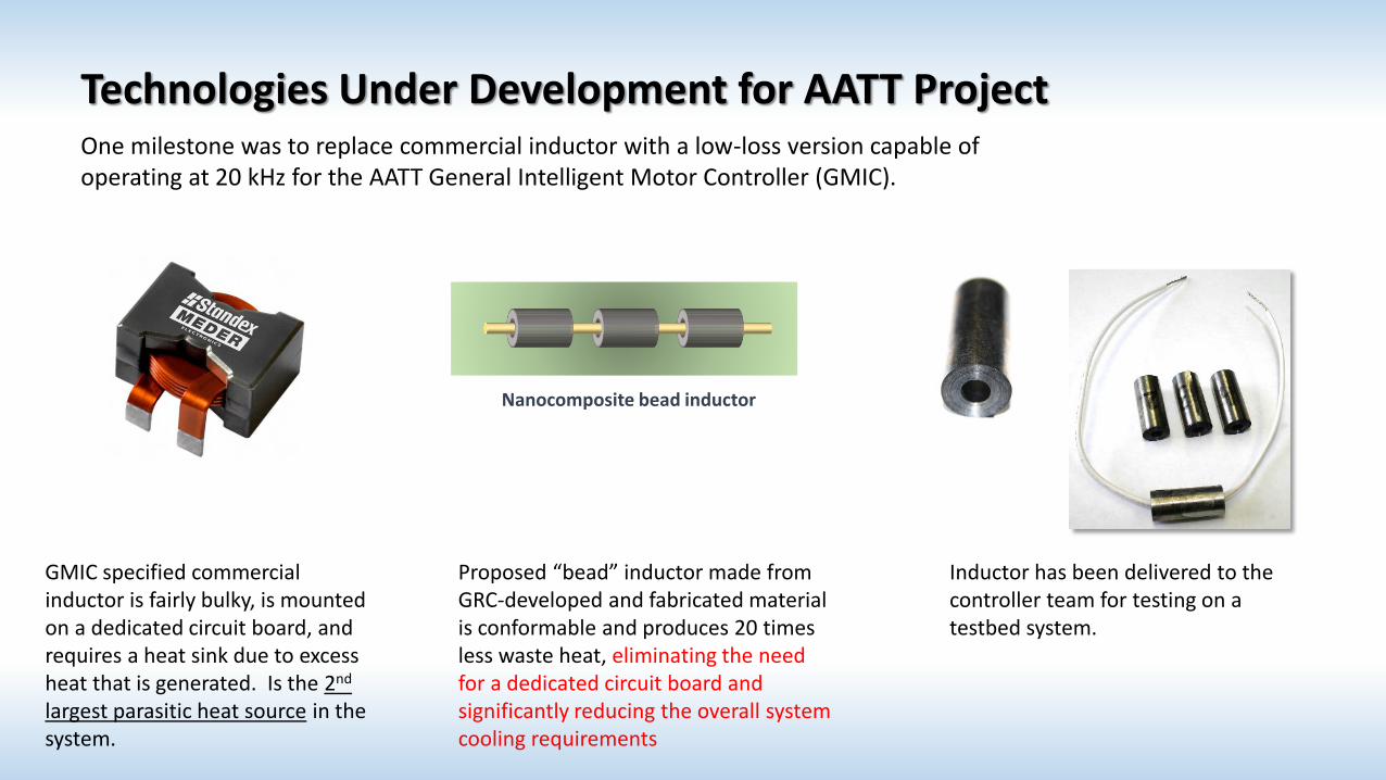
Technologies Under Development for AATT Project
Nanocomposite bead inductor
Proposed “bead” inductor made from GRC-developed and fabricated material is conformable and produces 20 times less waste heat, eliminating the need for a dedicated circuit board and significantly reducing the overall system cooling requirements
Inductor has been delivered to the controller team for testing on a testbed system.
One milestone was to replace commercial inductor with a low-loss version capable of operating at 20 kHz for the AATT General Intelligent Motor Controller (GMIC).
GMIC specified commercial inductor is fairly bulky, is mounted on a dedicated circuit board, and requires a heat sink due to excess heat that is generated. Is the 2nd
largest parasitic heat source in the system.
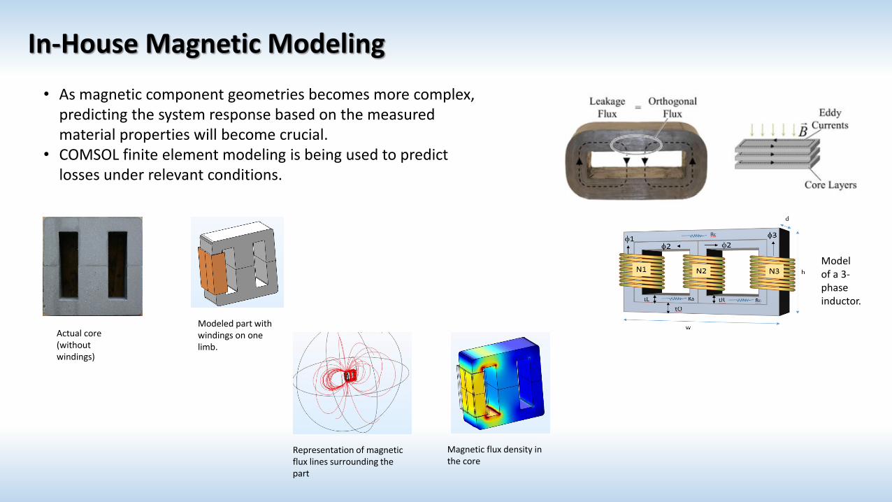
In-House Magnetic Modeling
• As magnetic component geometries becomes more complex, predicting the system response based on the measured material properties will become crucial.
• COMSOL finite element modeling is being used to predict losses under relevant conditions.
Actual core (without windings)
Modeled part with windings on one limb.
Representation of magnetic flux lines surrounding the part
Magnetic flux density in the core
Model of a 3-phase inductor.

Timeline of Magnetics Program
Finalized commercialization plan for 150-kg caster with industry and university partners
2014 2015 2016 2017
0.5 FTE, $0K: Began establishing magnetic research capabilities and identifying how these materials can enable electrified aircraft propulsion
1 FTE/$250K: arranged to transfer custom 3-kg caster to NASA to get nanocrystalline materials across manufacturing “valley of death”
Received disassembled caster
Reassembled caster and performed first run.
Delivered advanced inductor to AATT motor controller team
Won $500K/3-yr DOE proposal (RSAA) for photovoltaic transformer development
New CS hire in magnetics
Established Space Act with DOE for inductor development
Completed initial characterization lab build-up
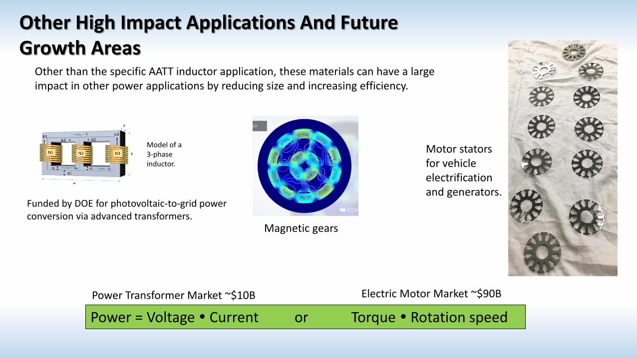
Other High Impact Applications And Future Growth Areas
Model of a 3-phase inductor.
Other than the specific AATT inductor application, these materials can have a large impact in other power applications by reducing size and increasing efficiency.
Funded by DOE for photovoltaic-to-grid power conversion via advanced transformers.
Motor stators for vehicle electrification and generators.
Power = Voltage Current or Torque Rotation speed
Power Transformer Market ~$10B Electric Motor Market ~$90B
Magnetic gears
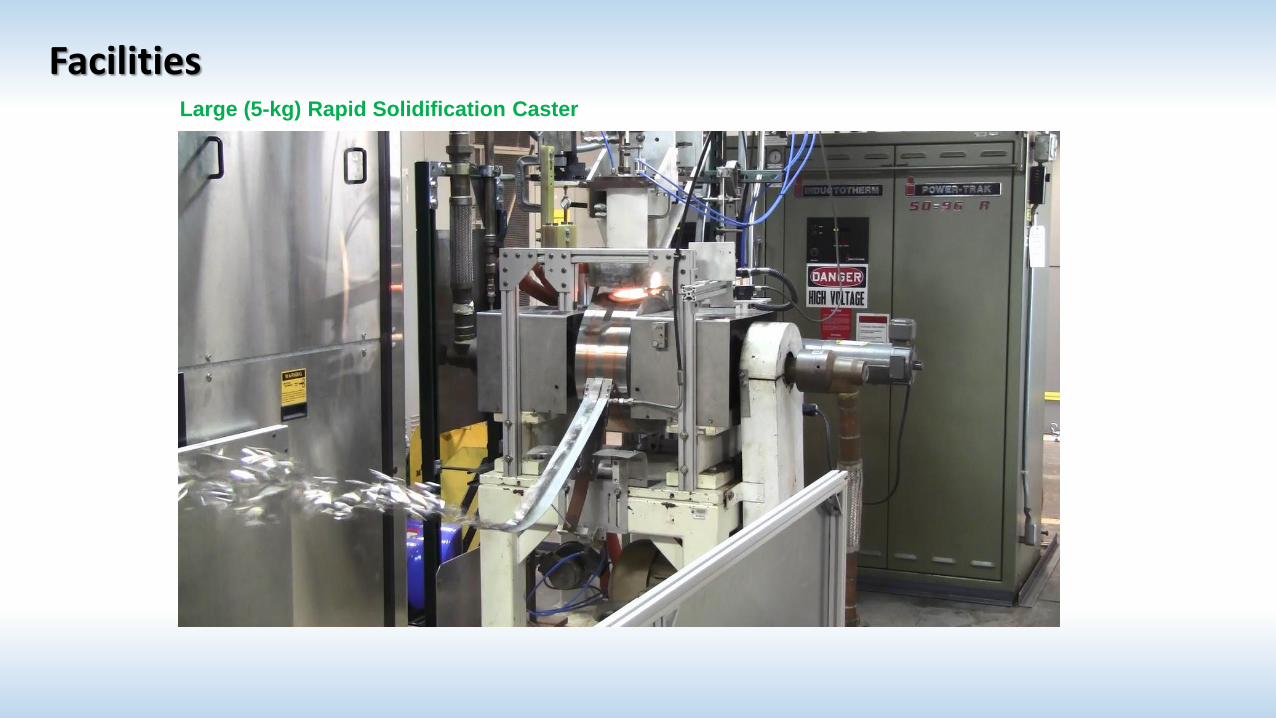
FacilitiesLarge (5-kg) Rapid Solidification Caster
• Produces 100 ft of 25-mm wide ribbon.• Allows for fabrication of magnetic materials in inert environment.• Rapid turn-around, several runs a day possible.
Small-Scale (50-g) Caster
Facilities
Facilities
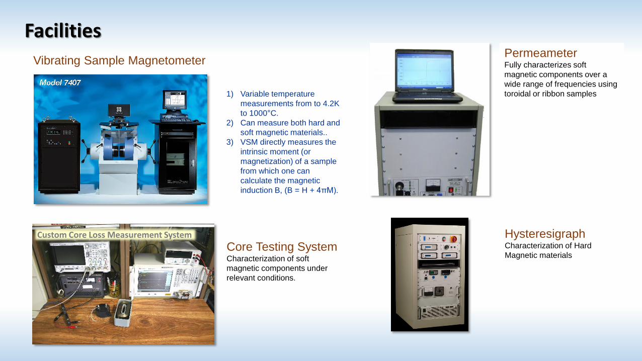
Vibrating Sample Magnetometer
1) Variable temperature
measurements from to 4.2K
to 1000°C.
2) Can measure both hard and
soft magnetic materials..
3) VSM directly measures the
intrinsic moment (or
magnetization) of a sample
from which one can
calculate the magnetic
induction B, (B = H + 4πM).
PermeameterFully characterizes soft
magnetic components over a
wide range of frequencies using
toroidal or ribbon samples
HysteresigraphCharacterization of Hard
Magnetic materials Core Testing SystemCharacterization of soft
magnetic components under
relevant conditions.
Custom Core Loss Measurement System
Facilities
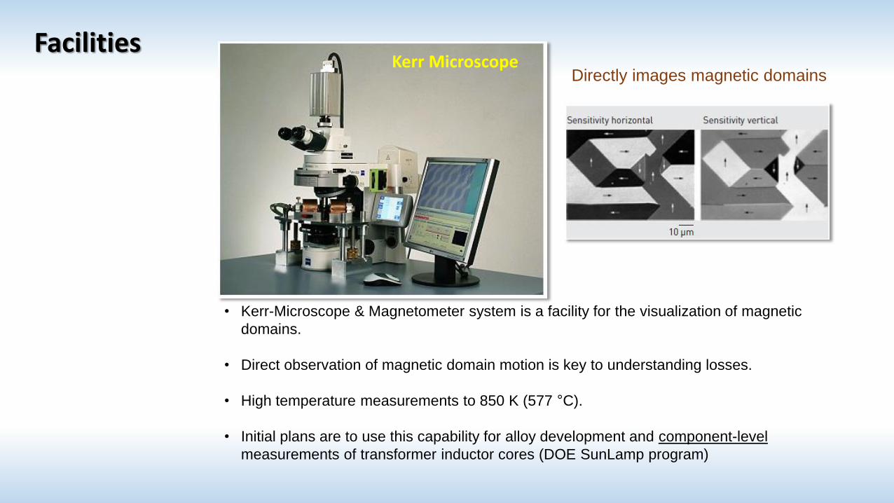
• Kerr-Microscope & Magnetometer system is a facility for the visualization of magnetic
domains.
• Direct observation of magnetic domain motion is key to understanding losses.
• High temperature measurements to 850 K (577 °C).
• Initial plans are to use this capability for alloy development and component-level
measurements of transformer inductor cores (DOE SunLamp program)
Kerr MicroscopeDirectly images magnetic domains
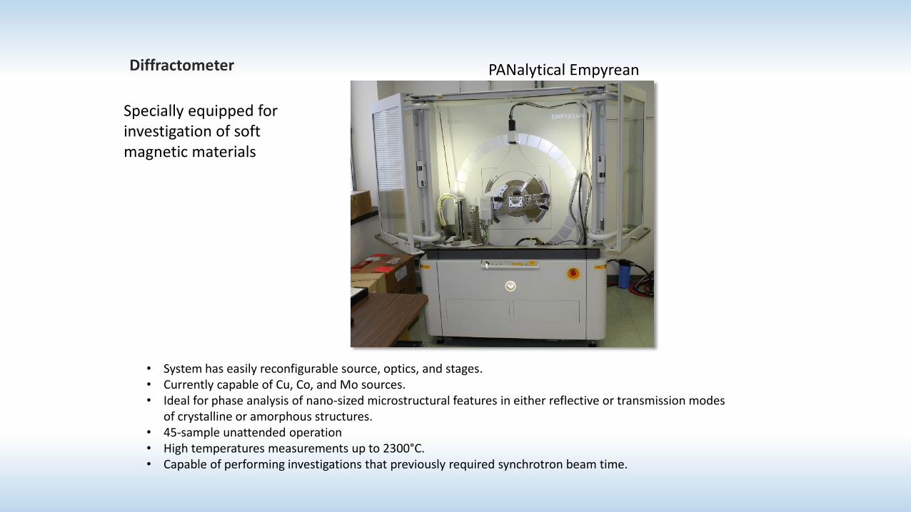
• System has easily reconfigurable source, optics, and stages.• Currently capable of Cu, Co, and Mo sources.• Ideal for phase analysis of nano-sized microstructural features in either reflective or transmission modes
of crystalline or amorphous structures.• 45-sample unattended operation• High temperatures measurements up to 2300°C.• Capable of performing investigations that previously required synchrotron beam time.
Diffractometer
Specially equipped for investigation of soft magnetic materials
PANalytical Empyrean
Recommended